4_1_alternatingcurrents
DESCRIPTION
goodTRANSCRIPT

Alternating Currents
1. The power is transmitted from a power house on high voltage ac because
(a) Electric current travels faster at higher volts
(b) It is more economical due to less power wastage
(c) It is difficult to generate power at low voltage
(d) Chances of stealing transmission lines are minimized
2. The potential difference V and the current i flowing through an instrument in an ac circuit
of frequency f are given by tV ωcos5= volts and I = 2 sin ωt amperes (where ω = 2πf). The
power dissipated in the instrument is
(a) Zero (b) 10 W
(c) 5 W (d) 2.5 W
3. Alternating current(A.C.) can not be measured by D.C. ammeter because
(a) A.C. cannot pass through D.C. ammeter
(b) Average value of complete cycle is zero
(c) A.C. is virtual
(d)A.C. changes its direction
4. In an ac circuit, peak value of voltage is 423 volts. Its effective voltage is
(a) 400 volts (b) 323 volts
(c) 300 volts (d) 340 volts
5. In an ac circuit I = 100 sin 200 πt. The time required for the current to achieve its peak
value will be
(a) sec100
1 (b) sec200
1
(c) sec300
1 (d) sec400
1
www.sakshieducation.com
www.sakshieducation.com
www.saks
hiedu
catio
n.com

6. An alternating current is given by the equation titii ωω sincos 21 += . The r.m.s. current is given
by
(a) )(2
121 ii + (b) 2
2)(2
1iii +
(c) 2/122
21 )(
2
1ii + (d) 2/12
221 )(
2
1ii +
7. The phase angle between e.m.f. and current in LCR series ac circuit is
(a) 0 to π / 2 (b) π / 4
(c) π / 2 (d) π
8. Current in the circuit is wattless, if
(a) Inductance in the circuit is zero
(b) Resistance in the circuit is zero
(c) Current is alternating
(d) Resistance and inductance both are zero
9. An alternating current of frequency '' f is flowing in a circuit containing a resistance R and
a choke L in series. The impedance of this circuit is
(a)R + 2πfL (b) 2222 4 LfR π+
(c) 22 LR + (d) fLR π22 +
10. A resonant ac circuit contains a capacitor of capacitance F610− and an inductor of .10 4 H− the
frequency of electrical oscillations will be
(a) Hz510 (b) 10 Hz
(c) Hzπ2
105
(d) Hzπ2
10
11. Power delivered by the source of the circuit becomes maximum when
(a) CL ωω = (b) C
Lω
ω 1=
(c) 2
1
−=C
Lω
ω (d) CL ωω =
www.sakshieducation.com
www.sakshieducation.com
www.saks
hiedu
catio
n.com
12. In a LCR circuit having L = 8.0 henry, C = 0.5 µF and R = 100 ohm in series. The
resonance frequency in per second is
(a) 600 radian (b) 600 Hz
(c) 500 radian (d) 500 Hz
13. In LCR circuit, the capacitance is changed from C to 4C. For the same resonant frequency,
the inductance should be changed from L to
(a) 2L (b) L / 2
(c) L / 4 (d) 4 L
14. 4.In a series LCR circuit, operated with an ac of angular frequencyω , the total impedance is
(a) 2/122 ])([ ωω CLR −+
(b) 2/12
2 1
−+ω
ωC
LR
(c) 2/12
2 1−
−+ω
ωC
LR
(d) 2/12
2 1)(
−+ω
ωωC
LR
15. For series LCR circuit, wrong statement is
(a) Applied e.m.f. and potential difference across resistance are in same phase.
(b) Applied e.m.f. and potential difference at inductor coil have phase difference of2/π .
(c) Potential difference at capacitor and inductor has phase difference of2/π .
(d) Potential difference across resistance and capacitor has phase difference of2/π .
16. In a purely resistive ac circuit, the current
(a) Lags behind the e.m.f. in phase
(b) Is in phase with the e.m.f.
(c) Leads the e.m.f. in phase
(d) Leads the e.m.f. in half the cycle and lags behind it in the other half
www.sakshieducation.com
www.sakshieducation.com
www.saks
hiedu
catio
n.com

17. The current in series LCR circuit will be maximum when ω is
(a) As large as possible
(b) Equal o natural frequency of LCR system
(c) LC
(d) LC/1
18. An inductor L and a capacitor C are connected in the circuit as shown in the figure. The
frequency of the power supply is equal to the resonant frequency of the circuit. Which
ammeter will read zero ampere
(a) 1A (b) 2A
(c) 3A (d) None of these
19. [A]: In LCR series circuit, current is maximum at resonance.
[R]: In LCR series circuit, impedance is minimum at resonance.
a) Both Assertion and Reason are true and reason is correct explanation of Assertion.
b) Both Assertion and Reason are true but reason is not the correct explanation of Assertion.
c) Assertion is true but reason is false.
d) Both assertion and reason are false.
20. [A]: If X c < XL, the phase factor is negative.
[R]: If X c < XL; current lags behind emf.
a) Both Assertion and Reason are true and reason is correct explanation of Assertion.
b) Both Assertion and Reason are true but reason is not the correct explanation of Assertion.
c) Assertion is true but reason is false.
d) Both assertion and reason are false.
A1
A2
A3
C
E = E0 sinωt
L
www.sakshieducation.com
www.sakshieducation.com
www.saks
hiedu
catio
n.com

21. [A]: Electric power is transmitted over long distances through conducting wires at high
voltage.
[R]: A Power loss is less when power is transmitted at high voltage.
a) Both Assertion and Reason are true and reason is correct explanation of Assertion.
b) Both Assertion and Reason are true but reason is not the correct explanation of Assertion.
c) Assertion is true but reason is false.
d) Both assertion and reason are false.
22. The voltage of an a.c source varies with time according to the relation E = 120 sin 100 π t
cos 100 πt. Then
i) The peak voltage of the source is 120 V
ii) The peak voltage = 60 V
iii) The peak voltage = 120/2 V
iv) The frequency of source voltage is 100 Hz
a) i) and ii) are correct b) ii) and iii) are correct
d) ii) and IV) are correct c) i) and iii) are correct
23. In the circuit shown below what will be the reading of the voltmeter and ammeter?
a) 2.2 A b) 1.2 A c) 4.2 A d) 0.5 A
www.sakshieducation.com
www.sakshieducation.com
www.saks
hiedu
catio
n.com

Key
1) b 2) a 3) b 4) c 5) d 6) c 7) a 8) b 9) b 10) c
11) b 12) c 13) c 14) b 15) c 16) b 17) d 18) c 19) a 20) a
21) a 22) c 23) a
Hints
1. Power loss 2(Voltage)
1∝
2.
+==2
sin5cos5πωω ttV and ti ωsin2=
Power φcos...... ××= smrsmr iV = 0
(Since2
πφ = , therefore 02
coscos == πφ )
3. In dc ammeter, a coil is free to rotate in the magnetic field of a fixed magnet.
If an alternating current is passed through such a coil, the torque will reverse its direction
each time the current changes direction and the average value of the torque will be zero.
4. Effective voltage VV
V osmr 300
2
423
2... ===
5. The current takes 4
T sec to reach the peak value.
In the given question secTT 100
1200
2 =⇒= ππ
∴Time to reach the peak value sec400
1=
6. 2/122
21
22
21 )(
2
1
2ii
iiirms +=
+=
7. (a)
www.sakshieducation.com
www.sakshieducation.com
www.saks
hiedu
catio
n.com

8. Because power ,2 Ri= if R = 0, then P = 0.
9. LXXRZ LL ω=+= ,22 and fπω 2=
2222 4 LfRZ π+=∴
10. HzLC πππ
ν2
10
10102
1
2
1 5
46=
×==
−−
11. (b)
12. Resonance frequency in radian/second is
secradLC
/500105.08
116
=××
==−
ω
13. 4
11 12
2211
LL
CLCL=⇒==ω
14. (b)
15. (c)
16. (b)
17. At resonant frequency current in series LCR circuit is maximum.
18. (c)
19. a
20. a
21. a
22. c
23. ( )22R L CV V V V= + −
( )22220 300 300 220R RV V V= + − ⇒ =
So reading in voltmeter = 220V
V = i R 220 100i⇒ = × ⇒ i = 2.2 A.
www.sakshieducation.com
www.sakshieducation.com
www.saks
hiedu
catio
n.com
D.C Circuits
1. Why the current does not rise immediately in a circuit containing inductance
(a) Because of induced emf
(b) Because of high voltage drop
(c) Because of low power consumption
(d) Because of Joule heating
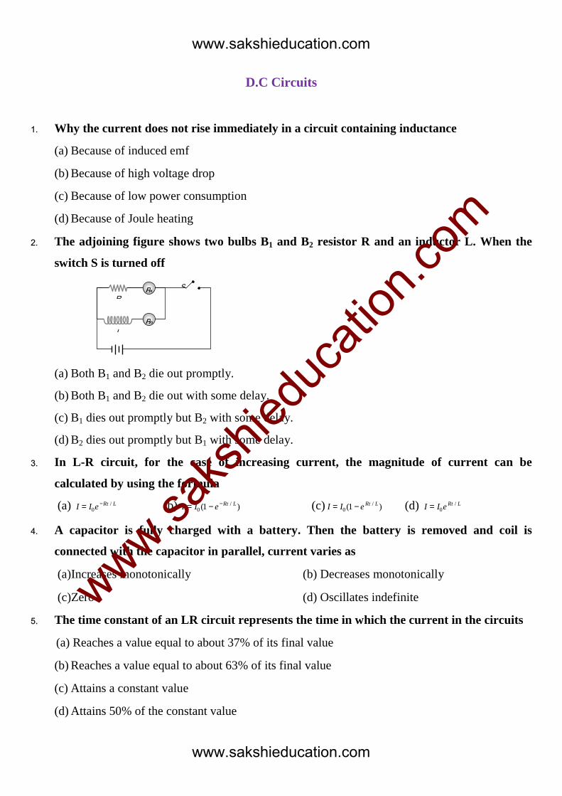
2. The adjoining figure shows two bulbs B1 and B2 resistor R and an inductor L. When the
switch S is turned off
(a) Both B1 and B2 die out promptly.
(b) Both B1 and B2 die out with some delay.
(c) B1 dies out promptly but B2 with some delay.
(d) B2 dies out promptly but B1 with some delay.
3. In L-R circuit, for the case of increasing current, the magnitude of current can be
calculated by using the formula
(a) LRteII /
0−= (b) )1( /
0LRteII −−= (c) )1( /
0LRteII −= (d)
LRteII /0=
4. A capacitor is fully charged with a battery. Then the battery is removed and coil is
connected with the capacitor in parallel, current varies as
(a)Increases monotonically (b) Decreases monotonically
(c)Zero (d) Oscillates indefinite
5. The time constant of an LR circuit represents the time in which the current in the circuits
(a) Reaches a value equal to about 37% of its final value
(b) Reaches a value equal to about 63% of its final value
(c) Attains a constant value
(d) Attains 50% of the constant value
R
L
S B1
B2
www.sakshieducation.com
www.sakshieducation.com
www.saks
hiedu
catio
n.com

6. The resistance and inductance of series circuit are Ω5 and 20H respectively. At the instant
of closing the switch, the current is increasing at the rate 4A-s. The supply voltage is
(a) 20 V (b) 80 V (c) 120 V (d) 100 V
7. In inductance L and a resistance R are first connected to a battery. After some time the
battery is disconnected but L and R remain connected in a closed circuit. Then the current
reduces to 37% of its initial value in
(a) RL sec (b) secL
R (c)
secR
L (d)
secLR
1
8. In an LR-circuit, time constant is that time in which current grows from zero to the
value (where 0I is the steady state current)
(a) 063.0 I (b) 050.0 I (c) 037.0 I (d) 0I
9. A solenoid has an inductance of 60 henrys and a resistance of 30 ohms. If it is connected
to a 100 volt battery, how long will it take for the current to reach %2.631 ≈−
e
e of its final
value?
(a)1 second (b) 2 seconds (c) e seconds (d) 2e seconds
10. A coil of inductance 300 mH and resistance Ω2 is connected to a source of voltageV2 . The
current reaches half of its steady state value in
(a) 0.15 s (b) 0.3 s (c) 0.05 s (d) 0.1 s
11. Find the time constant (in sµ ) for the given RC circuits in the given order respectively.
1 1R = Ω , 2 2R = Ω , 1 4C Fµ= , 2 2C Fµ=
I)
V
2C
1C
1R
2R
II)
V
2C
1C
1R
2R III)
V
2C
1C1R
2R
a) 18, 4, 8
9 b) 18,
8
9 , 4 c) 4, 18,
8
9 d) 4,
8
9 , 18
www.sakshieducation.com
www.sakshieducation.com
www.saks
hiedu
catio
n.com

12. An ideal coil of 10 Henry is joined in series with a resistance of 5 ohm and a battery of 5
volt. 2 second after joining, the current flowing in ampere in the circuit will be
1) e-1 2) (1-e–1) 3) (1-e) 4) e
13. An inductor of L = 400 mH and two resistors of 1 2R = Ω and 2 2R = Ω are connected to a
12V battery as shown in the figure. The internal resistance of the battery is negligible. The
switch is closed at time t = 0. The potential drop across ‘L’ as a function of time is
1) 312 te Vt
− 2) ( )/0.26 1 te V−− 3) 512 te V− 4) 56 te V−
14. The current in the given circuit is increasing with a rate 4 amp/ s. The charge on the
capacitor at an instant when the current in the circuit is 2 amp will be
1) 4 Cµ 2) 5 Cµ 3) 6 Cµ 4) 3 Cµ
15. The ratio of time constants in charging and discharging in the circuit shown in figure is
1) 1:1 2)1:2 3) 3:2 4) 2:3
www.sakshieducation.com
www.sakshieducation.com
www.saks
hiedu
catio
n.com

Key
1) a 2) c 3) b 4) d 5) b
6) b 7) c 8) a 9) b 10) d
11) b 12) b 13) c 14) c 15) c
Hints
6. (b)
−=
−L
Rt
eii 10L
Rt
L
Rt
eL
Rie
L
Ri
dt
di −−=
−−=⇒ .00
At t = 0; L
E
L
Ri
dt
di == 0 VEE
8020
4 =⇒=⇒
7. (c) When battery disconnected current through the circuit start decreasing exponentially
according to LRteii /0
−=
⇒ LRteii /0037.0 −= ⇒ LRte
e/1
37.0 −== ⇒ R
Lt =
8. (a) Current at any instant of time t after closing an L-R circuit is given by
−=
−t
L
R
eII 10
Time constant R
Lt =
−=−=
−=∴ −×−
eIeIeII R
L
L
R1
1)1(1 01
00
%6363.0718.2
11 00 ==
−= II Of 0I
9. (b) .sec230
60 ====R
Lt τ
10. (d)
−=
−L
Rt
eii 10 ⇒ For 20ii = ,
R
Lt 693.0=
⇒ sect 1.02
10300693.0
3
=××=−
www.sakshieducation.com
www.sakshieducation.com
www.saks
hiedu
catio
n.com

11. t = CR
( ) ( )1 1 2 1 2 18t C C R R sµ= + + =
1 2 1 22
1 2 1 2
8
9
C C R Rt
C C R R= × =
+ +
( ) 1 23 1 2
1 2
4R R
t C CR R
= + =+
12. 0 1R
tLi i e
− = −
5 2
1051
5i e
×− = −
. ( )11i e A−= −
13. 0
126
2i = = , 0. 1
Rt
Lp d v i e R−
= − −
3
2
400 1012. 12 1 2
2
t
p d e−−
×
= − −
p.d = 12 5te− volt.
14. E =di q
iR Ldt c
+ −
4 = 2 + 4 –3
q
6q cµ=
15. 1 2
2 1
2
2
R R R
R R
λλ
+= = Or 1
2
3
2
λλ
=
www.sakshieducation.com
www.sakshieducation.com
www.saks
hiedu
catio
n.com