4/3-proportional solenoid valve direct acting, with ... · 4/3-proportional solenoid valve direct...
TRANSCRIPT
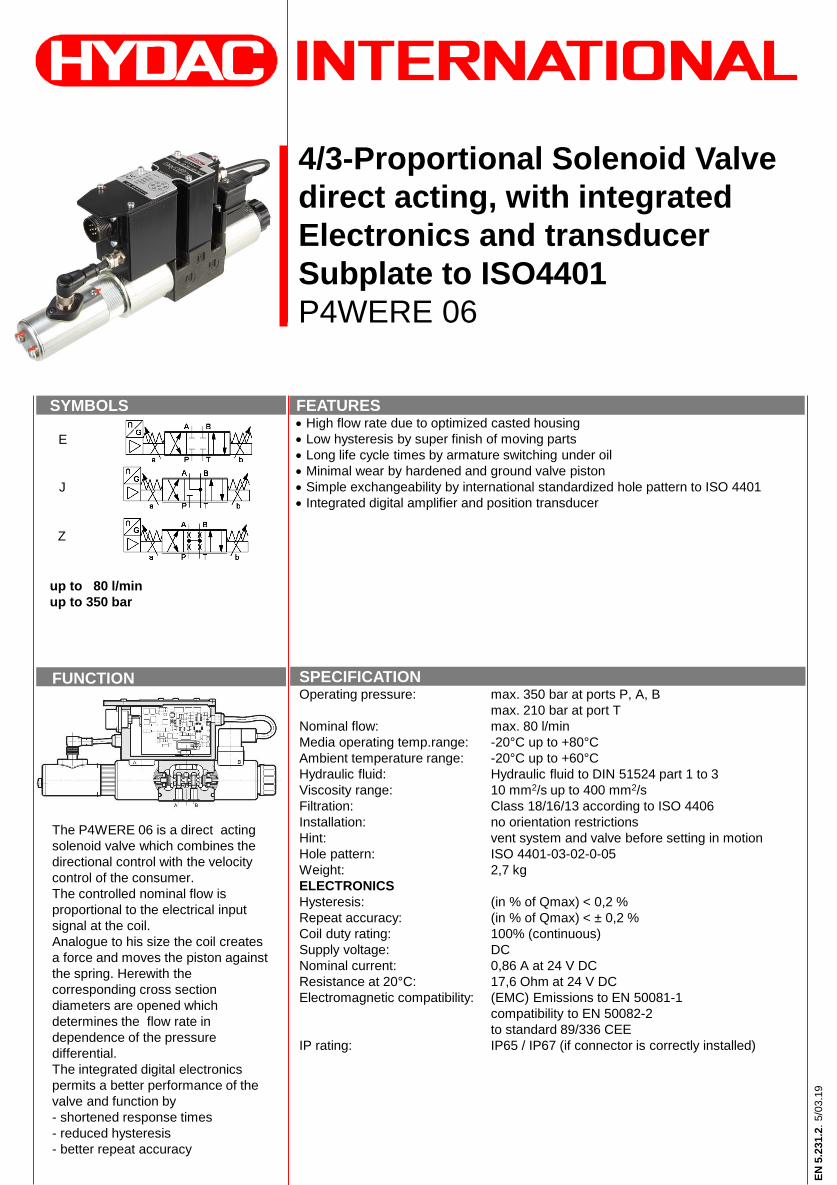
4/3-Proportional Solenoid Valve
direct acting, with integrated
Electronics and transducer
Subplate to ISO4401
P4WERE 06
FUNCTION
The P4WERE 06 is a direct acting
solenoid valve which combines the
directional control with the velocity
control of the consumer.
The controlled nominal flow is
proportional to the electrical input
signal at the coil.
Analogue to his size the coil creates
a force and moves the piston against
the spring. Herewith the
corresponding cross section
diameters are opened which
determines the flow rate in
dependence of the pressure
differential.
The integrated digital electronics
permits a better performance of the
valve and function by
- shortened response times
- reduced hysteresis
- better repeat accuracy
SYMBOLS
up to 80 l/min
up to 350 bar
E
J
Z
FEATURES High flow rate due to optimized casted housing
Low hysteresis by super finish of moving parts
Long life cycle times by armature switching under oil
Minimal wear by hardened and ground valve piston
Simple exchangeability by international standardized hole pattern to ISO 4401
Integrated digital amplifier and position transducer
SPECIFICATIONOperating pressure: max. 350 bar at ports P, A, B
max. 210 bar at port T
Nominal flow: max. 80 l/min
Media operating temp.range: -20°C up to +80°C
Ambient temperature range: -20°C up to +60°C
Hydraulic fluid: Hydraulic fluid to DIN 51524 part 1 to 3
Viscosity range: 10 mm2/s up to 400 mm2/s
Filtration: Class 18/16/13 according to ISO 4406
Installation: no orientation restrictions
Hint: vent system and valve before setting in motion
Hole pattern: ISO 4401-03-02-0-05
Weight: 2,7 kg
ELECTRONICS
Hysteresis: (in % of Qmax) < 0,2 %
Repeat accuracy: (in % of Qmax) < ± 0,2 %
Coil duty rating: 100% (continuous)
Supply voltage: DC
Nominal current: 0,86 A at 24 V DC
Resistance at 20°C: 17,6 Ohm at 24 V DC
Electromagnetic compatibility: (EMC) Emissions to EN 50081-1
compatibility to EN 50082-2
to standard 89/336 CEE
IP rating: IP65 / IP67 (if connector is correctly installed)
EN
5.2
31.2
.5/0
3.1
9
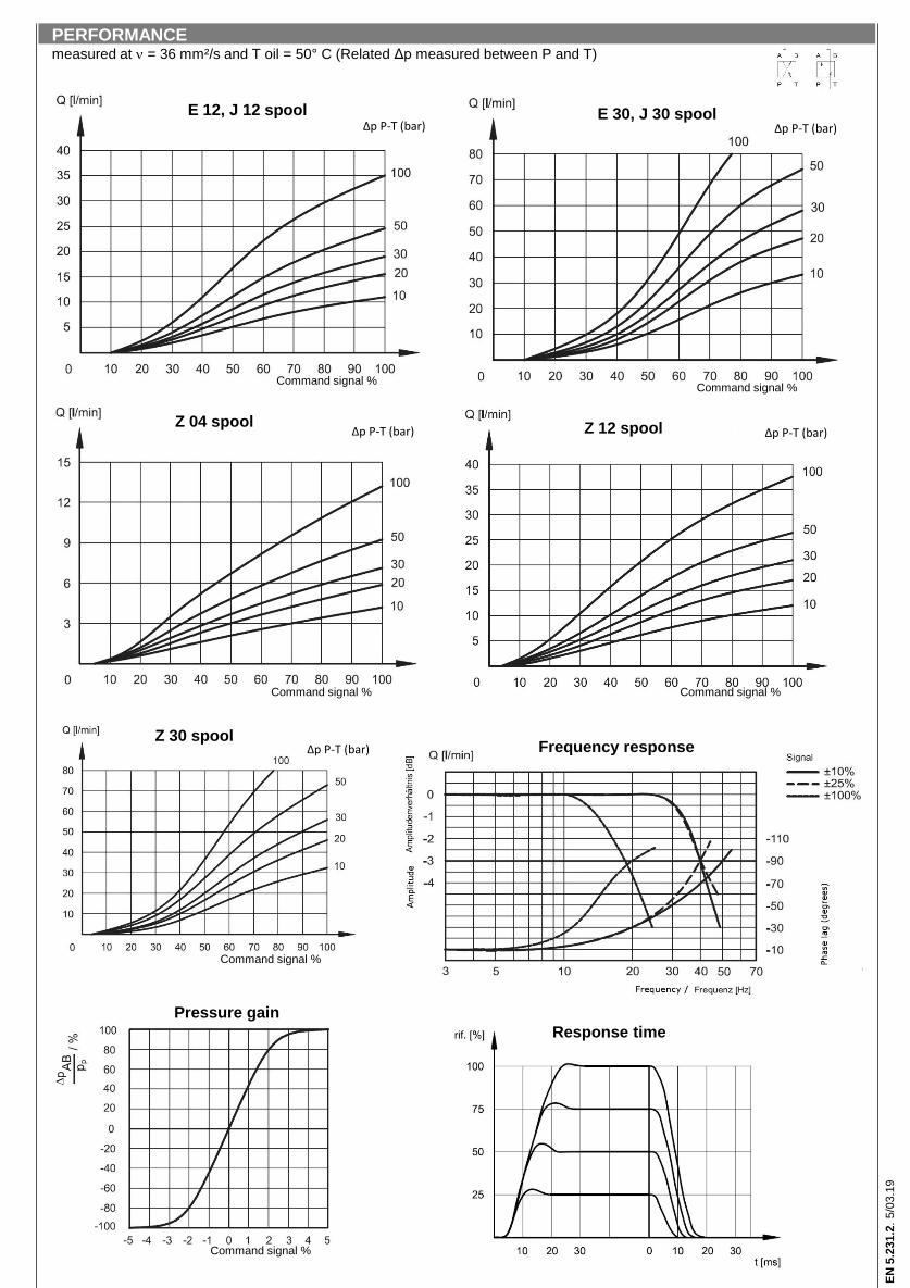
Δp P-T (bar) Δp P-T (bar)
Z
Z
ZΔp P-T (bar) Δp P-T (bar)
Δp P-T (bar)
PERFORMANCEmeasured at = 36 mm²/s and T oil = 50° C (Related Δp measured between P and T)
E 12, J 12 spool E 30, J 30 spool
Z 04 spool Z 12 spool
Z 30 spool
Pressure gain
Command signal %Command signal %
Command signal %Command signal %
Command signal %
Command signal %
Response time
Frequency response
EN
5.2
31.2
.5/0
3.1
9

ONBOARD ELECTRONICSParameter setting only with LIN-Bus
Power input: 25 W
Current draw: 1,88 A max.
Nominal voltage: 24 V DC (19 – 35 V DC, ripple max. 3 Vpp)
Coil duty rating: 100% (continuous)
Input signal E0: voltage signal ±10 V DC (Impedance Ri > 11 kOhm)
Input signal E1: current signal 4 – 20 mA (Impedance Ri = 500 Ohm)
Alert signals: Overload and overheating of Electronics, LVDT sensor
failure, cable break, power failure < 4 mA
Communication: LIN-Bus Interface
Electronics port: 7-pin MIL-C-5015-G (DIN-EN 175201-804)
EMC EN61000-6-4: Corresponding 2004/30 CE Standard
EMC EN61000-6-2: Corresponding 2004/30 CE Standard
IP rating: IP65 / IP67 (CEI EN 60529 Standard)
1) Mounting plate with sealing: 4 pcs O-rings 9.25 x 1.78 90 Shore
2) Manual override
3) Main connector (connector 7 pin DIN 43563 – IP65 PG11 EX7/L/10 not included in delivery, Mat. 6080324)
4) Transducer (Please do not dismount!)
Mounting screws: 4 pcs M5 x 30 10.9 (not included in delivery)
Torque: 5 Nm + 0,5 Nm
INTERFACE ISO 4401-03-02-0-05
(CETOP 4.2-4-03-350)
All dimensions in mm
DIMENSIONS
1) Valve with proportional coils
2) Housing for electronics
3) Digital amplifier
4) Main connector
EN
5.2
31.2
.5/0
3.1
9
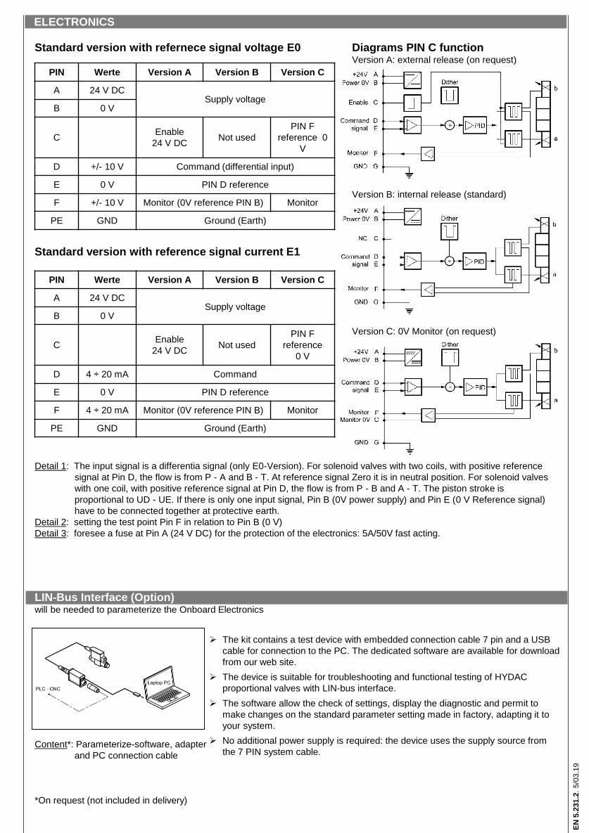
Standard version with refernece signal voltage E0 Diagrams PIN C functionVersion A: external release (on request)
Version B: internal release (standard)
Standard version with reference signal current E1
Version C: 0V Monitor (on request)
Detail 1: The input signal is a differentia signal (only E0-Version). For solenoid valves with two coils, with positive reference
signal at Pin D, the flow is from P - A and B - T. At reference signal Zero it is in neutral position. For solenoid valves
with one coil, with positive reference signal at Pin D, the flow is from P - B and A - T. The piston stroke is
proportional to UD - UE. If there is only one input signal, Pin B (0V power supply) and Pin E (0 V Reference signal)
have to be connected together at protective earth.
Detail 2: setting the test point Pin F in relation to Pin B (0 V)
Detail 3: foresee a fuse at Pin A (24 V DC) for the protection of the electronics: 5A/50V fast acting.
LIN-Bus Interface (Option)will be needed to parameterize the Onboard Electronics
Content*: Parameterize-software, adapter
and PC connection cable
*On request (not included in delivery)
PIN Werte Version A Version B Version C
A 24 V DCSupply voltage
B 0 V
CEnable
24 V DCNot used
PIN F
reference 0
V
D +/- 10 V Command (differential input)
E 0 V PIN D reference
F +/- 10 V Monitor (0V reference PIN B) Monitor
PE GND Ground (Earth)
PIN Werte Version A Version B Version C
A 24 V DCSupply voltage
B 0 V
CEnable
24 V DCNot used
PIN F
reference
0 V
D 4 ÷ 20 mA Command
E 0 V PIN D reference
F 4 ÷ 20 mA Monitor (0V reference PIN B) Monitor
PE GND Ground (Earth)
The kit contains a test device with embedded connection cable 7 pin and a USB
cable for connection to the PC. The dedicated software are available for download
from our web site.
The device is suitable for troubleshooting and functional testing of HYDAC
proportional valves with LIN-bus interface.
The software allow the check of settings, display the diagnostic and permit to
make changes on the standard parameter setting made in factory, adapting it to
your system.
No additional power supply is required: the device uses the supply source from
the 7 PIN system cable.
ELECTRONICS
EN
5.2
31.2
.5/0
3.1
9

P4WERE 06 E 12 D01 - 24 PG E0 A /V
Basic model
Proportional solenoid valve with integrated electronics
Nominal size
6
Spool symbol
E, J, Z
other symbols on request
Nominal volume flow
01 = 1 l/min
04 = 4 l/min
12 = 12 l/min
20 = 20 l/min
30 = 30 l/min
Type
D01 = standard type with manual override
Nominal voltage
24 = 24 V DC
Coil connector
PG = DIN conntector to EN175301-803
Input signal
E0 = ±10 V
E1 = 4 - 20 mA
PIN C function
See „Diagrams PIN C function“
Sealing material
V = FKM (standard)
N = NBR (optional)
In the casing of electronics, a 7-pole port for connecting with external devices is integrated.
The cable diameter for the connector (cable and connector are not included in delivery) has to be min. 8 mm and max. 10 mm.
at Δp = 10 bar P-T
MODEL CODE
EN
5.2
31.2
.5/0
3.1
9

Annotation
The technical information in this brochure are
relating to the operating conditions and
applications.
At deviant applications and/or operating
conditions please contact the technical dept.
Technical information are subject to
technical modifications.
HYDAC Fluidtechnik GmbH
Justus-von-Liebig-Str.
66280 Sulzbach / Saar
Tel.: 06897 / 509 -01
Fax: 06897 / 509 -598
Email: [email protected]
Model code Part No.
P4WERE 06 E12 D01-24PG E0A/V 3565232
P4WERE 06 E12 D01-24PG E1A/V 3869492
P4WERE 06 E30 D01-24PG E0A/V 3565233
P4WERE 06 E30 D01-24PG E1A/V 3709464
P4WERE 06 J12 D01-24PG E0A/V 3565246
P4WERE 06 J12 D01-24PG E1A/V 3771361
P4WERE 06 J30 D01-24PG E0A/V 3565247
P4WERE 06 J30 D01-24PG E1A/V 3601758
P4WERE 06 Z04 D01-24PG E0A/V 3723163
P4WERE 06 Z04 D01-24PG E1A/V 3718599
P4WERE 06 Z12 D01-24PG E0A/V 3676781
P4WERE 06 Z12 D01-24PG E1A/V 3761019
P4WERE 06 Z30 D01-24PG E0A/V 3566640
P4WERE 06 Z30 D01-24PG E1A/V 3708097
other types on request
EN
5.2
31.2
.5/0
3.1
9
STANDARD MODELS