4308 ieee transactions on wireless communications, vol. 6, no
TRANSCRIPT

4308 IEEE TRANSACTIONS ON WIRELESS COMMUNICATIONS, VOL. 6, NO. 12, DECEMBER 2007
Joint Scale-Lag Diversity in Wideband MobileDirect Sequence Spread Spectrum Systems
Adam R. Margetts, Member, IEEE, Philip Schniter, Senior Member, IEEE,and Ananthram Swami, Senior Member, IEEE
Abstract— We consider the effect of mobility on a widebanddirect sequence spread spectrum (DSSS) communication system,and study a scale-lag Rake receiver capable of leveraging thediversity that results from mobility. A wideband signal has alarge bandwidth-to-center frequency ratio, such that the typicalnarrowband Doppler spread assumptions do not apply to mobilechannels. Instead, we assume a more general temporal scalingphenomenon, i.e., a dilation of the transmitted signal’s timesupport. Based on a uniform ring of scatterers model, wedetermine that the wideband scattering function, which quantifiesthe average scale spreading, has a “bathtub-shaped” scale profile.We compare the performances of a scale-lag Rake and afrequency-lag Rake, each capable of leveraging the diversitythat results from mobility. Such analysis applies, for example, toultra-wideband (UWB) radio frequency channels and underwaterwideband acoustic channels.
Index Terms— Mobile wireless communication, scale-lag diver-sity, spread spectrum, wideband systems.
I. INTRODUCTION
W IDEBAND communication systems are defined as hav-ing a fractional bandwidth—the ratio of single-sided
bandwidth to center frequency—that exceeds 0.20 [1] [2].Otherwise, the system is called narrowband. We are interestedin studying the effect of mobility (i.e., temporal variation in thephysical geometries between transmitter, receiver, and scatter-ers) on wideband communications systems and in designingtransceivers capable of leveraging the potential diversity gainsthat result from multipath propagation in mobile environments.
First, it is important to note that the combined effects ofmultipath and mobility on transmitted signals are modeledquite differently for wideband systems than for their narrow-band counterparts. For example, in narrowband systems witha dense ring of scatterers surrounding the receiver, mobilityimparts a spreading of the signal in the frequency-domain thatis commonly referred to as Doppler spreading [3, p. 809]. Inwideband communication systems employing direct sequence
Manuscript received March 4, 2005; revised October 25, 2005, June 27,2006, and March 21, 2007; accepted August 15, 2007. The associate editorcoordinating the review of this paper and approving it for publication was S.Zhou. This work was supported by the Ohio Space Grant Consortium andby the Office of Naval Research. Portions of this work were presented at the2004 Asilomar Conference on Signals, Systems, and Computers, and at the2005 International Conference on Acoustics, Speech, and Signal Processing.
A. Margetts is with MIT Lincoln Laboratory, 244 Wood St., Lexington,MA 02420 USA (e-mail: [email protected]).
P. Schniter is with the Department of Electrical and Computer Engineer-ing, The Ohio State University, 2015 Neil Ave., 616 Dreese Laboratories,Columbus, OH 43210 USA (e-mail: [email protected]).
A. Swami is with the Army Research Laboratory, 2800 Powder Mill Rd.,Adelphi, MD 20783 USA (e-mail: [email protected]).
Digital Object Identifier 10.1109/TWC.2007.05141.
spread spectrum (DSSS)—the focus of this manuscript—theeffects of mobility in the multipath mobile environment are notwell described by frequency-domain spreading, but rather bytime-domain scale spreading. Note that scale-spreading arisesfrom the same fundamental mechanism that causes Dopplerspreading. For example, changing the time scale of a singlesinusoid is equivalent to shifting the signal in frequency. Byscale spreading, we mean that several copies of the transmittedsignal combine at the receiver, each with a different dilationof the time support of the original signal. In addition, eachcopy may be attenuated and temporally delayed by a differentamount.
When the different propagation paths are characterizedby independent dilations and delays, the fading inherent tomultipath propagation can be mitigated by using diversityreception. For wideband DSSS signaling, we propose a scale-lag Rake receiver that extracts this diversity.1 The scale-lag Rake employs a basis composed of shift-dilates of thetransmitted waveform in order to match the scale-lag spreadinginduced by the wideband channel. In general, the transmitwaveform could be designed to optimally enable the scale-lagdiversity; however, for practical considerations, we constrainthe transmit waveform to be a DSSS signal. The analysiscan be applied to underwater acoustic systems [4] as wellas to radio frequency ultra-wideband (UWB) systems [5]. Inparticular, this paper considers mobile wideband systems withlimited available lag diversity where extracting dilation diver-sity has the potential to significantly improve performance [6].
The rest of the paper is organized as follows. Section IIdescribes the DSSS waveform and defines the transformationused to model the input-output characteristics of the widebandchannel. Section III motivates the scale-lag Rake receiver anddiscusses the scale-resolution property of a wideband DSSSwaveform. Furthermore, a low complexity implementation ofthe scale-lag basis projection is proposed. In Section IV, thewideband scattering function, which quantifies the scale-lagchannel energy profile, is examined and scale-lag diversity isdefined. Section V supports the analysis by providing numeri-cal results for a system employing second-derivative Gaussianchip pulses. Finally, we provide conclusions in Section VI.
II. SYSTEM MODEL
A. Transmit Signal
Throughout, we assume baseband DSSS signaling, wherethe transmitted signal s(t) results from linearly modulating a
1The possibility of a scale-lag receiver was mentioned in [3], but no detailswere developed.
1536-1276/07$25.00 c© 2007 IEEE
MARGETTS et al.: JOINT SCALE-LAG DIVERSITY IN WIDEBAND MOBILE DIRECT SEQUENCE SPREAD SPECTRUM SYSTEMS 4309
TX RXv
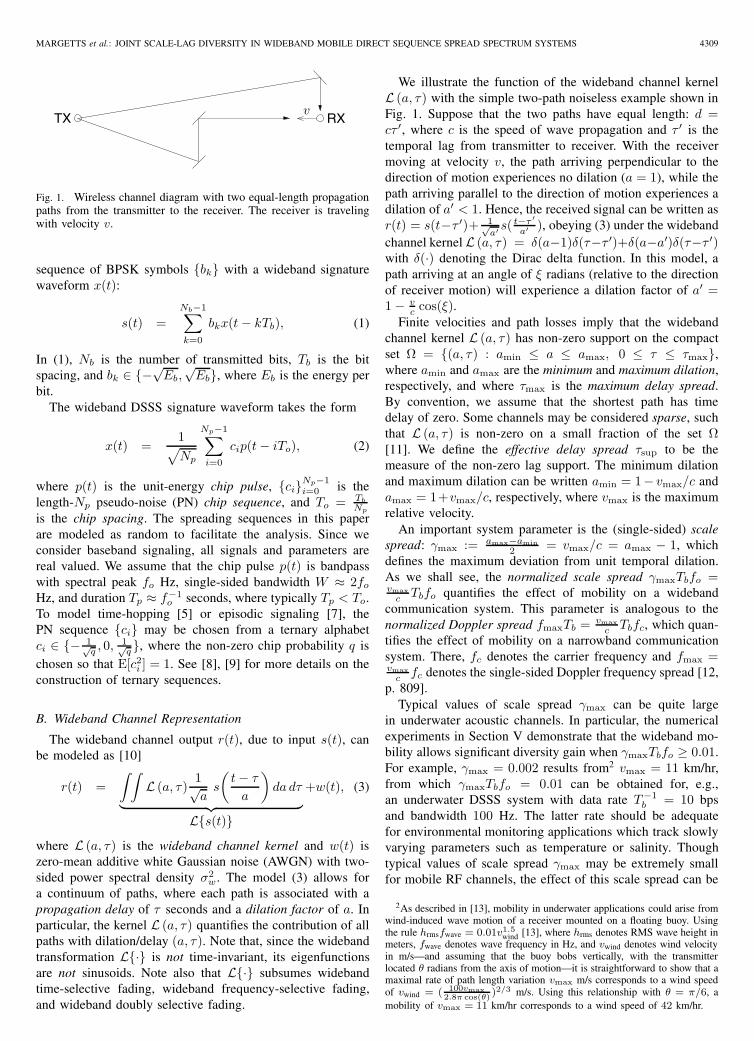
Fig. 1. Wireless channel diagram with two equal-length propagationpaths from the transmitter to the receiver. The receiver is travelingwith velocity v.
sequence of BPSK symbols {bk} with a wideband signaturewaveform x(t):
s(t) =Nb−1∑k=0
bkx(t − kTb), (1)
In (1), Nb is the number of transmitted bits, Tb is the bitspacing, and bk ∈ {−√
Eb,√
Eb}, where Eb is the energy perbit.
The wideband DSSS signature waveform takes the form
x(t) =1√Np
Np−1∑i=0
cip(t − iTo), (2)
where p(t) is the unit-energy chip pulse, {ci}Np−1i=0 is the
length-Np pseudo-noise (PN) chip sequence, and To = Tb
Np
is the chip spacing. The spreading sequences in this paperare modeled as random to facilitate the analysis. Since weconsider baseband signaling, all signals and parameters arereal valued. We assume that the chip pulse p(t) is bandpasswith spectral peak fo Hz, single-sided bandwidth W ≈ 2fo
Hz, and duration Tp ≈ f−1o seconds, where typically Tp < To.
To model time-hopping [5] or episodic signaling [7], thePN sequence {ci} may be chosen from a ternary alphabetci ∈ {− 1√
q , 0, 1√q}, where the non-zero chip probability q is
chosen so that E[c2i ] = 1. See [8], [9] for more details on the
construction of ternary sequences.
B. Wideband Channel Representation
The wideband channel output r(t), due to input s(t), canbe modeled as [10]
r(t) =∫ ∫
L (a, τ)1√a
s
(t − τ
a
)da dτ
︸ ︷︷ ︸L{s(t)}
+w(t), (3)
where L (a, τ) is the wideband channel kernel and w(t) iszero-mean additive white Gaussian noise (AWGN) with two-sided power spectral density σ2
w. The model (3) allows fora continuum of paths, where each path is associated with apropagation delay of τ seconds and a dilation factor of a. Inparticular, the kernel L (a, τ) quantifies the contribution of allpaths with dilation/delay (a, τ). Note that, since the widebandtransformation L{·} is not time-invariant, its eigenfunctionsare not sinusoids. Note also that L{·} subsumes widebandtime-selective fading, wideband frequency-selective fading,and wideband doubly selective fading.
We illustrate the function of the wideband channel kernelL (a, τ) with the simple two-path noiseless example shown inFig. 1. Suppose that the two paths have equal length: d =cτ ′, where c is the speed of wave propagation and τ ′ is thetemporal lag from transmitter to receiver. With the receivermoving at velocity v, the path arriving perpendicular to thedirection of motion experiences no dilation (a = 1), while thepath arriving parallel to the direction of motion experiences adilation of a′ < 1. Hence, the received signal can be written asr(t) = s(t−τ ′)+ 1√
a′ s(t−τ ′
a′ ), obeying (3) under the widebandchannel kernel L (a, τ) = δ(a−1)δ(τ−τ ′)+δ(a−a′)δ(τ−τ ′)with δ(·) denoting the Dirac delta function. In this model, apath arriving at an angle of ξ radians (relative to the directionof receiver motion) will experience a dilation factor of a′ =1 − v
c cos(ξ).Finite velocities and path losses imply that the wideband
channel kernel L (a, τ) has non-zero support on the compactset Ω = {(a, τ) : amin ≤ a ≤ amax, 0 ≤ τ ≤ τmax},where amin and amax are the minimum and maximum dilation,respectively, and where τmax is the maximum delay spread.By convention, we assume that the shortest path has timedelay of zero. Some channels may be considered sparse, suchthat L (a, τ) is non-zero on a small fraction of the set Ω[11]. We define the effective delay spread τsup to be themeasure of the non-zero lag support. The minimum dilationand maximum dilation can be written amin = 1− vmax/c andamax = 1+vmax/c, respectively, where vmax is the maximumrelative velocity.
An important system parameter is the (single-sided) scalespread: γmax := amax−amin
2 = vmax/c = amax − 1, whichdefines the maximum deviation from unit temporal dilation.As we shall see, the normalized scale spread γmaxTbfo =vmax
c Tbfo quantifies the effect of mobility on a widebandcommunication system. This parameter is analogous to thenormalized Doppler spread fmaxTb = vmax
c Tbfc, which quan-tifies the effect of mobility on a narrowband communicationsystem. There, fc denotes the carrier frequency and fmax =vmax
c fc denotes the single-sided Doppler frequency spread [12,p. 809].
Typical values of scale spread γmax can be quite largein underwater acoustic channels. In particular, the numericalexperiments in Section V demonstrate that the wideband mo-bility allows significant diversity gain when γmaxTbfo ≥ 0.01.For example, γmax = 0.002 results from2 vmax = 11 km/hr,from which γmaxTbfo = 0.01 can be obtained for, e.g.,an underwater DSSS system with data rate T−1
b = 10 bpsand bandwidth 100 Hz. The latter rate should be adequatefor environmental monitoring applications which track slowlyvarying parameters such as temperature or salinity. Thoughtypical values of scale spread γmax may be extremely smallfor mobile RF channels, the effect of this scale spread can be
2As described in [13], mobility in underwater applications could arise fromwind-induced wave motion of a receiver mounted on a floating buoy. Usingthe rule hrmsfwave = 0.01v1.5
wind [13], where hrms denotes RMS wave height inmeters, fwave denotes wave frequency in Hz, and vwind denotes wind velocityin m/s—and assuming that the buoy bobs vertically, with the transmitterlocated θ radians from the axis of motion—it is straightforward to show that amaximal rate of path length variation vmax m/s corresponds to a wind speedof vwind = ( 100vmax
2.8π cos(θ))2/3 m/s. Using this relationship with θ = π/6, a
mobility of vmax = 11 km/hr corresponds to a wind speed of 42 km/hr.
4310 IEEE TRANSACTIONS ON WIRELESS COMMUNICATIONS, VOL. 6, NO. 12, DECEMBER 2007
significant when Tbfo, the signal’s time-bandwidth product,is large enough. As an example, vmax = 67.5 km/hr yieldsγmax = 6.25×10⁻⁸ in RF channels, from which γmaxTbfo =0.01 can be obtained for, e.g., a DSSS system with data rateT−1
b = 25 kbps and bandwidth W = 8 GHz.We shall see that the normalized effective delay spread
τsupfo quantifies the effect of multipath time-dispersion inwideband systems. Since fo ≈ W/2, the normalized effectivedelay spread can be approximated by 1
2τsupW , which isknown to quantify the effect of time-dispersion in narrowbandsystems. As an example of a system with limited lag diversity,if we choose τmax = τsup = 10 ms in the previously describedacoustic example3, we find a normalized effective delay spreadof τsupfo = 0.5.
From the previous RF example, given a maximum delayspread of τmax = 2.5 μs, we find a normalized maximumdelay spread of τmaxfo = 1.0 × 10⁴. However, vehicularchannels are often sparse, as shown in [11]. For example, in95% of measured channels only 5 rays were significant4, whilein 79% of measured channels only 2 rays were significant.Since, at bandwidth W Hz, each ray contributes 1
2W secondsto the effective delay spread τsup, a 2-ray channel would yielda normalized effective delay spread of τsupfo = 0.5. Thesediverse rays can be resolved by a DSSS system as shown inSection III.
Throughout the paper, we assume that the maximum delayspread is much less than the symbol spacing, i.e., τmax �Tb, in which case guardbands can be inserted to preventinter-symbol interference (ISI) with a small loss in spectralefficiency. This assumption is reasonable for DSSS with largeprocessing gain and is often made for impulse-radio UWBRF systems [14, p.34] and DSSS underwater acoustic systems[4]. It can be confirmed that τmax = 0.1Tb for the previouslydescribed underwater acoustic example and τmax = 0.0625Tb
for the previously described RF example.
III. SCALE-LAG RAKE RECEIVER
A. Wideband Scale-Lag Canonical Model Representation
Sayeed and Aazhang [15] derived a narrowband canoni-cal model for parsimonious representation of a narrowbandbaseband-equivalent received signal and, after making sta-tistical assumptions on the narrowband baseband-equivalentchannel kernel, analyzed the performance of a frequency-lagRake receiver, which exploits Doppler-lag channel diversity ina mobile spread-spectrum system. Motivated by the narrow-band canonical model, Balan et al. [3] derived a canonicalmodel for the wideband transformation. A similar widebanddecomposition was proposed independently in [16].
The wideband canonical model parameterizes the widebandtransformation as a weighted sum of delay and dilation oper-ations [3]:
L{s(t)} =∑m
∑n
lm,n1
am/2�
s
(t − nt�a
m�
am�
), (4)
3A delay spread of 10 ms is said to be typical for underwater acousticchannels [13].
4We reason that the number of rays in our example RF channel is similarto the number of rays in the measured 19 MHz-bandwidth channels in [11],since [11] concludes “a majority of the delay spread seen in the currentenvironment is due to single reflections from large man-made scatterers.”
(a)
(b)
0
0
x(t)
1√a
x(
ta
)· · ·
· · ·
Tb
aTb
Tp
t
t
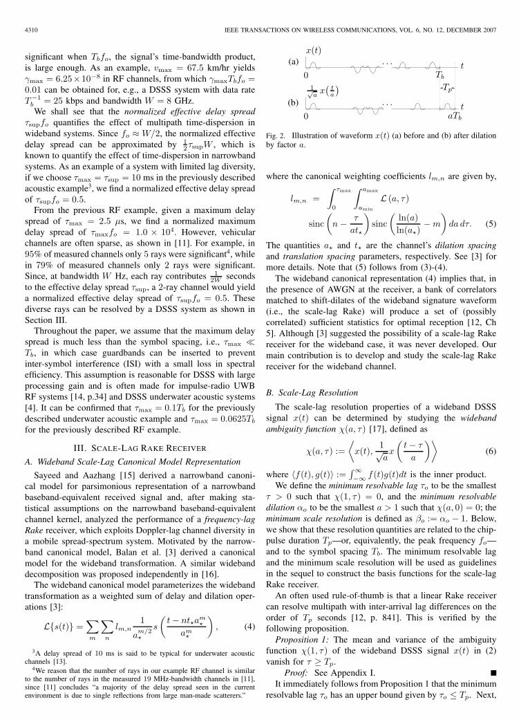
Fig. 2. Illustration of waveform x(t) (a) before and (b) after dilationby factor a.
where the canonical weighting coefficients lm,n are given by,
lm,n =∫ τmax
0
∫ amax
amin
L (a, τ)
sinc(
n − τ
at�
)sinc
(ln(a)ln(a�)
− m
)da dτ. (5)
The quantities a� and t� are the channel’s dilation spacingand translation spacing parameters, respectively. See [3] formore details. Note that (5) follows from (3)-(4).
The wideband canonical representation (4) implies that, inthe presence of AWGN at the receiver, a bank of correlatorsmatched to shift-dilates of the wideband signature waveform(i.e., the scale-lag Rake) will produce a set of (possiblycorrelated) sufficient statistics for optimal reception [12, Ch5]. Although [3] suggested the possibility of a scale-lag Rakereceiver for the wideband case, it was never developed. Ourmain contribution is to develop and study the scale-lag Rakereceiver for the wideband channel.
B. Scale-Lag Resolution
The scale-lag resolution properties of a wideband DSSSsignal x(t) can be determined by studying the widebandambiguity function χ(a, τ) [17], defined as
χ(a, τ) :=⟨
x(t),1√ax
(t − τ
a
)⟩(6)
where 〈f(t), g(t)〉 :=∫∞−∞ f(t)g(t)dt is the inner product.
We define the minimum resolvable lag τo to be the smallestτ > 0 such that χ(1, τ) = 0, and the minimum resolvabledilation αo to be the smallest a > 1 such that χ(a, 0) = 0; theminimum scale resolution is defined as βo := αo − 1. Below,we show that these resolution quantities are related to the chip-pulse duration Tp—or, equivalently, the peak frequency fo—and to the symbol spacing Tb. The minimum resolvable lagand the minimum scale resolution will be used as guidelinesin the sequel to construct the basis functions for the scale-lagRake receiver.
An often used rule-of-thumb is that a linear Rake receivercan resolve multipath with inter-arrival lag differences on theorder of Tp seconds [12, p. 841]. This is verified by thefollowing proposition.
Proposition 1: The mean and variance of the ambiguityfunction χ(1, τ) of the wideband DSSS signal x(t) in (2)vanish for τ ≥ Tp.
Proof: See Appendix I.It immediately follows from Proposition 1 that the minimum
resolvable lag τo has an upper bound given by τo ≤ Tp. Next,

MARGETTS et al.: JOINT SCALE-LAG DIVERSITY IN WIDEBAND MOBILE DIRECT SEQUENCE SPREAD SPECTRUM SYSTEMS 4311
the scale resolution property of a DSSS signal is linked to thetime-bandwidth product. Let a result in a dilation greater thanor equal to one chip-pulse duration Tp (illustrated by Fig. 2),i.e.,
aTb − Tb ≥ Tp ⇔ a ≥ 1 +Tp
Tb. (7)
Now consider the following proposition, which gives a rule-of-thumb for the minimum resolvable dilation αo.
Proposition 2: The mean and variance of χ(a, 0) vanish fora ≥ 1 + Tp
Tbif and only if the chip pulse p(t) has zero DC
component.Proof: See Appendix I.
From Proposition 2, we see that, for zero-DC pulses, theminimum scale resolution is upper bounded by βo ≤ Tp
Tb.
Since the chip-pulse duration Tp and the peak frequency fo areinversely proportional, we can say that the scale resolution βo
is on the order of (Tbfo)−1—the inverse of the time-bandwidthproduct.
C. Example: Second-Derivative Gaussian Chip Pulse
We now use a second-derivative Gaussian chip pulse toillustrate the scale and lag resolution properties of a DSSSsignal. The pulse waveform is defined as [18]
p(t) =√
fo4√
32π√3
[1 − 2(πfot)2
]e−(πfot)2 , (8)
with Fourier transform
P (f) =√
fo4√
32π√3
2√πf2
o
(f
fo
)2
e− f2
f2o . (9)
Time and frequency plots of the second-derivative Gaussianare shown in Fig. 3. From Fig. 3(a), we argue that the chippulse duration5 is roughly Tp = 2
foseconds. From Fig. 3(b),
we see that the chip pulse (8) has zero DC component6 andconfirm that the peak frequency equals fo.
It is shown in Appendix I that, for large spreading gain Np
and practical values of dilation (i.e., a ≈ 1),7 the widebandambiguity function can be approximated in the mean-squaresense as
χ(a, τ) ≈ χ(a, τ),
:=∫ 1
0
χp(1, τ + (a − 1)zTb)dz (10)
where
χp(a, τ) :=⟨
p(t),1√ap
(t − τ
a
)⟩(11)
is the wideband ambiguity function of the chip pulse p(t). Theambiguity function for the second derivative Gaussian pulse
5Some authors [19], [20] define duration differently and conclude Tp =7
πfo√
2= 1.58
fo.
6There exist other zero-DC pulses, e.g. the modified duobinary pulse [12,p. 563].
7Recall that 1 − vmaxc
≤ a ≤ 1 + vmaxc
, where, usually, vmaxc
is verysmall compared to 1.
−1 −0.5 0 0.5 1−1
0
1
2
0 0.5 1 1.5 2 2.5 30
0.2
0.4
0.6
0.8
(a)
(b)
tfo
f/fo
Fig. 3. Plot of (a) p(t) (time domain) and (b) P (f) (frequencydomain) for the second-derivative Gaussian chip pulse (i.e., “Mexicanhat wavelet”) defined in (8).
−4−2
02
4
−4
−2
0
2
4−0.6
−0.4
−0.2
0
0.2
0.4
0.6
0.8
1
Normalized scale, (a − 1)foTb Normalized lag, τfo
Fig. 4. Approximate wideband ambiguity function χ(a, τ ) with thesecond-derivative Gaussian chip pulse (8).
(8) can be written as [21, p. 63]
χp(a, τ) =
f(a)(
4π4f4o τ4 − 12π2f2
o τ2(1 + a2) + 3(1 + a2)2)
exp(−π2f2
o τ2
1 + a2
), (12)
where f(a) := 43
√2a5
(1+a2)9 . Plugging (12) into (10) yields anapproximation for the wideband ambiguity function (6), whichis plotted in Fig. 4. (Note that the approximation χ(a, τ) is notdirectly a function of the chip spacing To.) For comparison,Fig. 5 plots the deterministic wideband ambiguity functionχ(a, τ) corresponding to a length-128 i.i.d. random binarychip sequence {ci} with chip spacing To = Tp (i.e., non-overlapping chips). Note the similarity between Fig. 4 andFig. 5.
We now find the minimum resolvable dilation αo andminimum resolvable lag τo for DSSS signaling over second-derivative Gaussian chip pulses. To do so, we examine the

4312 IEEE TRANSACTIONS ON WIRELESS COMMUNICATIONS, VOL. 6, NO. 12, DECEMBER 2007
−4−2
02
4
−4
−2
0
2
4−0.6
−0.4
−0.2
0
0.2
0.4
0.6
0.8
1
Normalized scale, (a − 1)foTb Normalized lag, τfo
Fig. 5. Deterministic wideband ambiguity function χ(a, τ ) of aDSSS waveform x(t) composed of a length-128 i.i.d. random binarysequence modulating second-derivative Gaussian chip pulses withchip spacing To = 2
fo.
−2 −1.5 −1 −0.5 0 0.5 1 1.5 2−0.5
0
0.5
1
−2 −1.5 −1 −0.5 0 0.5 1 1.5 2−1
−0.5
0
0.5
1
(a)
(b)
(a − 1)Tbfo
τfo
(a − 1) = 0.55Tbfo
τ = 0.236fo
τ = 0.744fo
Fig. 6. Plot of (a) χ(a, 0) and (b) χ(1, τ ) for DSSS waveformemploying second-derivative Gaussian chip-pulses.
cross-sections χ(a, 0) and χ(1, τ), plotted in Fig. 6(a) andFig. 6(b), respectively. From Fig. 6(a), we see that the min-imum resolvable dilation is approximately αo = 1 + 0.55
Tbfo,
yielding minimum scale resolution βo = 0.55Tbfo
. We also seethat χ(a, 0) approaches zero again at a = 1 + 1
Tbfoand
vanishes for a ≥ 1 + 2Tbfo
= 1 + Tp
Tb, as predicted by
Proposition 2. From Fig. 6(b), we see that the minimumresolvable lag is approximately τo = 0.236
fo. We also see that
χ(1, τ) approaches zero again at τ = 0.744fo
and vanishes forτ ≥ 2
fo= Tp, as predicted by Proposition 1.
D. Connection to Radar, Sonar, and Wavelets
The reader will notice that if x(t) satisfies the waveletadmissibility conditions [22, p. 125], then χ(a, τ) is thecontinuous wavelet transform (CWT) with respect to x(t). Itis easily verified that if the chip pulse p(t) is admissible, then
the waveform x(t) is also admissible. A necessary conditionof admissibility is for the waveform to have a zero at DC;hence, an arbitrarily chosen wavelet will satisfy Proposition 2.In this paper, wavelet sequences are used to extract scalediversity from the channel; wavelets have also been used fortime-varying system identification [23], [24]. The connectionbetween wavelet analysis and wideband processing for Radarand Sonar is studied in [25], and experimental results arereported in [26].
The affect of time dilation on spread-spectrum signals issometimes called “code Doppler.” A study of the effect ofcode Doppler on timing acquisition was performed in [27].We are not aware of any attempts to exploit the presenceof code Doppler for diversity gain. Code Doppler will alsooccur if there is a sampling frequency mismatch between thetransmitter digital to analog converter (DAC) and the receiveranalog to digital converter (ADC), in which case every pathis dilated by the same amount.
The scale and lag resolution analysis we have performed forDSSS signals could be applied to Radar/Sonar estimation oftarget velocity and range. Consider the following recent paperson the topic. An exploration on the connection of the widebandambiguity function (6) for arbitrary motion (not just constantvelocity) and its constant-velocity narrowband approximationis found in [28]. In [29], the authors investigate the dilationresolution properties of random wideband signals, which aregenerated via a Gaussian noise source. In [30], a ternary-modulated sequence was used to estimate range and velocity.In [31], the authors estimate range by determining when thepulse first arrives. In [32], a Cramer-Rao lower bound (CRLB)on the estimation error of velocity and range via widebandambiguity function analysis is calculated based on the Mellintransform [33]. One avenue of future work is to design optimalCRLB-minimizing chip-pulses and sequences by applying theMellin transform analysis in [32] to our ambiguity-functionapproximations.
E. Choice of Rake Basis Functions
Motivated by the scale-lag wideband channel parameteriza-tion in Section III-A and the scale-lag resolution properties inSection III-B, we choose, as basis functions for demodulatingthe kth bit, the set of dilated-delayed versions of the DSSSwaveform x(t) [c.f., (2)]:
x(k)m,n(t) =
1√am
o
x
(t − ntoa
mo − kTb
amo
), (13)
where ao is the dilation-spacing parameter and to is thetranslation-spacing parameter (c.f. Section III-A). We defineγo := ao − 1 as the scale-spacing parameter.
Recalling the relationship between the minimum resolutionquantities (αo, τo) and the system parameters (fo, Tb), weset the scale-spacing and translation-spacing equal to γo =
kγ
Tbfoand to = kt
fo, respectively, where kγ and kt are Rake
design parameters. Note that, for the case of second-derivativeGaussian chip pulses, the choices kγ = 0.55 and kt = 0.236yield dilation-spacing and translation-spacing equal to theminimum resolvable dilation and lag, respectively.
The scale-lag Rake receiver projects the received signalonto the scale-lag basis functions {x(k)
m,n(t) for (m, n) ∈ I}

MARGETTS et al.: JOINT SCALE-LAG DIVERSITY IN WIDEBAND MOBILE DIRECT SEQUENCE SPREAD SPECTRUM SYSTEMS 4313
Scal
eSc
ale
Lag
Lag
γo
γo
to
to
τ
τ(a)
(b)
γ
γ
r(k)1,0
r(k)1,0
r(k)1,1 r
(k)1,2
r(k)0,0
r(k)0,0
r(k)0,1
r(k)0,1
r(k)0,2
r(k)0,2
r(k)−1,0
r(k)−1,0
r(k)−1,1 r
(k)−1,2
Fig. 7. Example scale-lag Rake configurations: (a) rectangular, and(b) “T-shaped”.
and subsequently combines the projection coefficients to inferthe kth bit. The index set I specifies the coordinates of activeRake fingers. For example, Fig. 7(a) shows a Rake with arectangular grid of scale-lag fingers and Fig. 7(b) shows aRake with two active non-trivial scale fingers. Note that theconventional lag-only Rake is a special case of the scale-lagRake with I = {(0, n) : n = 0, . . . , N}, i.e., with only trivialscale fingers. Note also that, for typical values of dilation-spacing (i.e., ao ≈ 1), a Taylor series approximation aroundthe point ao = 1 gives am
o ≈ 1+m(ao − 1) = 1+mγo. Thus{x(k)
m,n(t)}m∈Z constitutes an approximately uniform samplingof the scale domain with sampling interval γo.
Using the wideband channel transformation (3), we nowanalyze {r(k)
m,n}, the scale-lag Rake projection coefficients forthe kth bit:
r(k)m,n = 〈x(k)
m,n(t), r(t)〉,
=Nb−1∑l=0
bl
⟨x(k)
m,n(t),L{x(t − lTb)}⟩
︸ ︷︷ ︸≈0, for l �=k since τmax�Tb
+ 〈x(k)m,n(t), w(t)〉︸ ︷︷ ︸
w(k)m,n
,
≈ bk
⟨x(k)
m,n(t),L{x(t − kTb)}⟩
︸ ︷︷ ︸h(k)m,n
+w(k)m,n,
= bkh(k)m,n + w(k)
m,n. (14)
In (14), {h(k)m,n} are the channel coefficients and {w(k)
m,n}are the noise coefficients. Collecting {r(k)
m,n}(m,n)∈I into thevector rk, we can write
rk = bkhk + wk (15)
where vectors hk and wk are defined similarly. Because thechannel produces finite scaling and delay, there is negligibleenergy in the scale-lag Rake components corresponding to
the following set of indices: {m, n | m > �γmaxγo
� or m <
−�γmaxγo
�, n > � τsupto
� or n < 0}. Thus, in the case that Ispecifies a rectangular array of Rake fingers with dimension(2M+1)×(N+1), it would be advisable to choose M ≈ γmax
γo
and N ≈ τsupto
in order to limit complexity while capturing asignificant fraction of the received signal energy.
F. Reduced-Complexity Rake Implementation
Anticipating the high expense of accurate wideband analogfiltering, we propose a low-complexity means of scale-lagprojection. For ease of illustration, we focus on a (2M +1)×(N + 1) rectangular array of Rake fingers. For this setup, wepropose to feed the output of a single chip-matched filter intoa bank of samplers with rates {(am
o to)−1, m = −M, . . . , M}.Each sampler output is connected to a tapped-delay line withfingers down-sampled to the chip-pulse rate 1
To. (See Fig. 8.)
Here, we have assumed, for simplicity, that the chip-spacingTo is a multiple of the translation-spacing to, i.e., To
to= Nt for
Nt ∈ N. Focusing on the 0th bit and dropping the superscriptsin (14), the proposed structure can be justified as follows.
rm,n
=∫
xm,n(t)r(t)dt,
=1
am/2o
Np−1∑i=0
ci√Np
∫p(
t−ntoamo −iToam
o
amo
)r(t)dt,
=1
am/2o
Np−1∑i=0
ci√Np
p(− t
amo
)∗r(t)
∣∣∣t=(n+iNt)am
o to
,
≈ 1
am/2o
Np−1∑i=0
ci√Np
p (−t) ∗r(t)∣∣∣∣t=(n+iNt)am
o to
,
=1
am/2o
Np−1∑i=0
ci√Np
zm,n[i], (16)
where ∗ denotes linear convolution and where
zm,n[i] := p (−t) ∗r(t)∣∣∣∣t=(n+iNt)am
o to
. (17)
The approximation in (16) is premised on the idea that dilatingthe Tp-duration chip pulse p(t) by am
o has a negligible effecton the Rake outputs.8 Note that, since Tb � Tp, dilating p(t)is insignificant in comparison to dilating the Tb-duration bitwaveform x(t).
Notice that the translation-spacing to is analogous to thesampling period in lag-only Rake reception (i.e., the m = 0components); the scale components (i.e., m �= 0) are obtainedby slightly lengthening or shortening the sampling period.An interesting question is how sampling frequency offset willaffect the performance of the scale-lag Rake. We conjecturethat as long as the sampling of the scale-lag plane is “dense”enough to collect all the received energy, then samplingfrequency offsets will not adversely impact performance.
8A similar approximation is used for analog-to-digital conversion in anarrowband DSSS system, i.e., the Doppler distortion of chip pulses areignored [15].
4314 IEEE TRANSACTIONS ON WIRELESS COMMUNICATIONS, VOL. 6, NO. 12, DECEMBER 2007
. . .
. . .
. . .
...
...
...
...
ntoamo
nto
ntoa−mo
p(−t)r(t)
zzz
zzz
zzz
z1,0[i] z1,1[i] z1,N [i]
z0,0[i] z0,1[i] z0,N [i]
z−1,0[i] z−1,1[i] z−1,N [i]
↓ Nt↓ Nt
↓ Nt ↓ Nt
↓ Nt ↓ Nt ↓ Nt
↓ Nt
↓ Nt
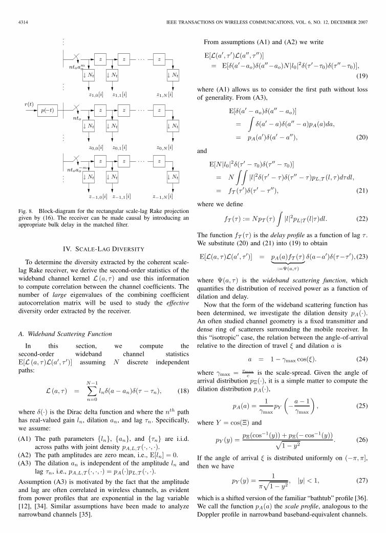
Fig. 8. Block-diagram for the rectangular scale-lag Rake projectiongiven by (16). The receiver can be made causal by introducing anappropriate bulk delay in the matched filter.
IV. SCALE-LAG DIVERSITY
To determine the diversity extracted by the coherent scale-lag Rake receiver, we derive the second-order statistics of thewideband channel kernel L (a, τ) and use this informationto compute correlation between the channel coefficients. Thenumber of large eigenvalues of the combining coefficientautocorrelation matrix will be used to study the effectivediversity order extracted by the receiver.
A. Wideband Scattering Function
In this section, we compute thesecond-order wideband channel statisticsE[L (a, τ)L(a′, τ ′)] assuming N discrete independentpaths:
L (a, τ) =N−1∑n=0
lnδ(a − an)δ(τ − τn), (18)
where δ(·) is the Dirac delta function and where the nth pathhas real-valued gain ln, dilation an, and lag τn. Specifically,we assume:
(A1) The path parameters {ln}, {an}, and {τn} are i.i.d.across paths with joint density pA,L,T (·, ·, ·).
(A2) The path amplitudes are zero mean, i.e., E[ln] = 0.(A3) The dilation an is independent of the amplitude ln and
lag τn, i.e., pA,L,T (·, ·, ·) = pA(·)pL,T (·, ·).Assumption (A3) is motivated by the fact that the amplitudeand lag are often correlated in wireless channels, as evidentfrom power profiles that are exponential in the lag variable[12], [34]. Similar assumptions have been made to analyzenarrowband channels [35].
From assumptions (A1) and (A2) we write
E[L(a′, τ ′)L(a′′, τ ′′)]= E[δ(a′−ao)δ(a′′−ao)N |l0|2δ(τ ′−τ0)δ(τ ′′−τ0)],
(19)
where (A1) allows us to consider the first path without lossof generality. From (A3),
E[δ(a′ − ao)δ(a′′ − ao)]
=∫
δ(a′ − a)δ(a′′ − a)pA(a)da,
= pA(a′)δ(a′ − a′′), (20)
and
E[N |l0|2δ(τ ′ − τ0)δ(τ ′′ − τ0)]
= N
∫ ∫|l|2δ(τ ′ − τ)δ(τ ′′ − τ)pL,T (l, τ)dτdl,
= fT (τ ′)δ(τ ′ − τ ′′), (21)
where we define
fT (τ) := NpT (τ)∫
|l|2pL|T (l|τ)dl. (22)
The function fT (τ) is the delay profile as a function of lag τ .We substitute (20) and (21) into (19) to obtain
E[L(a, τ)L(a′, τ ′)] = pA(a)fT (τ)︸ ︷︷ ︸:=Ψ(a,τ)
δ(a−a′)δ(τ−τ ′), (23)
where Ψ(a, τ) is the wideband scattering function, whichquantifies the distribution of received power as a function ofdilation and delay.
Now that the form of the wideband scattering function hasbeen determined, we investigate the dilation density pA(·).An often studied channel geometry is a fixed transmitter anddense ring of scatterers surrounding the mobile receiver. Inthis “isotropic” case, the relation between the angle-of-arrivalrelative to the direction of travel ξ and dilation a is
a = 1 − γmax cos(ξ). (24)
where γmax = vmaxc is the scale-spread. Given the angle of
arrival distribution pΞ(·), it is a simple matter to compute thedilation distribution pA(·),
pA(a) =1
γmaxpY
(−a − 1
γmax
), (25)
where Y = cos(Ξ) and
pY (y) =pΞ(cos−1(y)) + pΞ(− cos−1(y))√
1 − y2. (26)
If the angle of arrival ξ is distributed uniformly on (−π, π],then we have
pY (y) =1
π√
1 − y2, |y| < 1, (27)
which is a shifted version of the familiar “bathtub” profile [36].We call the function pA(a) the scale profile, analogous to theDoppler profile in narrowband baseband-equivalent channels.

MARGETTS et al.: JOINT SCALE-LAG DIVERSITY IN WIDEBAND MOBILE DIRECT SEQUENCE SPREAD SPECTRUM SYSTEMS 4315
B. Wideband Channel Coefficient Correlation
Recalling (15), the noise vector wk is Gaussian distributedwith zero mean; hence, the optimal bit error rate (BER)-minimizing coherent receiver is the whitened matched filter[12, p. 603], which assumes knowledge of the channel coef-ficients hk and noise correlation matrix Rw := E[wkwH
k ] =σ2
wRx, where the elements of Rx are inner products of theform 〈x(k)
m,n(t), x(k)m′,n′(t)〉 over m, m′ ∈ {−M, . . . , M} and
n, n′ ∈ {0, . . . , N}. In practice, the receiver would estimatethe channel coefficients hk.
The decision statistic bk is [12]
bk = fHk (R−1/2
x )Hrk, (28)
= bk‖fk‖2 + fTk (R−1/2
x )Hwk. (29)
where (R−1/2x )H is the whitening matrix and fk =
(R−1/2x )Hhk is the combining coefficient vector. The matrix
R1/2x is, e.g., the Cholesky decomposition of the matrix Rx
and can be computed offline.In the following, we focus on the kth bit and drop the
bit index notation. The signal-to-noise ratio is defined asSNR := Eb/σ2
w and the theoretical BER expression for asystem employing BPSK signaling and coherent receptionwith perfect channel state information, assuming real-valuedGaussian coefficients, can be computed as [21, pp. 24-25]
Pe =1π
∫ π/2
0
κ−1∏i=0
(λiSNR
sin2 θ+ 1)−1/2
dθ, (30)
≤ 12
κ−1∏i=0
(λiSNR + 1)−1/2. (31)
where {λi}κi=1, κ := |I| are the eigenvalues of the
combining vector correlation matrix Σ := E[ffH ] =(R−1/2
x )HRhR−1/2x , and Rh := E[hhT ] is the the channel
autocorrelation matrix.Similar to [37], we define the effective diversity order
extracted by the receiver as the negative slope of the log-logplot of Pe versus SNR at a particular finite SNR. An exactexpression for the effective diversity order is omitted herebecause it is complicated and does not yield insight into theconnection between the eigenvalues and the BER performance.Instead, the following piecewise-linear upper bound derivedfrom (31) is provided whose negative slope approximates theeffective diversity order:
log Pe ≤ −B(SNR)2
log SNR + C(SNR), (32)
where B(SNR) := |{λbigj }| is the number of large eigenvalues
defined as {λbigj } = {λj |λj > 1
SNR} and C(SNR) := log 12 −
12 log
∏B−1j=0 λbig
j . We denote the negative slope B(SNR)2 of
the upper bound (32) as the approximate effective diversityorder extracted by the receiver at a particular SNR. Note thatB(SNR) is a piecewise-constant function of SNR and thatwhen SNR > 1
min{λi}κi=1
, the approximate effective diversity
order B(SNR)2 equals the traditionally defined (i.e., asymptotic)
diversity order, which, for our real-valued Gaussian channel,is κ
2 , the number of non-zero eigenvalues divided by two.9
9The halving is an artifact of the real-valued nature of the Gaussian channelcoefficients.
To obtain the channel coefficient correlation matrix Rh, weuse the uncorrelated scattering property (23) to find
E[h(k)m,nh
(k′)m′,n′ ] =∫ τmax
0
∫ 1+γmax
1−γmax
Ψ(a, τ) E[χ(
amo
a ,ntoam
o −τ−k(a−1)Tb
a
)
χ
(am′
o
a ,n′toam′
o −τ−k′(a−1)Tb
a
)]dadτ,
≈∫ τmax
0
∫ 1+γmax
1−γmax
Ψ(a, τ)χ(
amo
a ,ntoam
o −τ−k(a−1)Tb
a
)
χ
(am′
o
a ,n′toam′
o −τ−k′(a−1)Tb
a
)dadτ, (33)
The approximation above is due to Lemma 4 in Appen-dix I, which makes the case that E[χ(a, τ)χ(a′, τ ′)] ≈χ(a, τ)χ(a′, τ ′) when a and a′ are near unity and Np is large.With the approximations10 am
o
a ≈ 1 + mγo − (a − 1) andntoam
o −τ−i(a−1)Tb
a ≈ nto − τ − i(a − 1)Tb, the correlation(33) can be approximated by
E[h(k)m,nh
(k′)m′,n′ ] ≈∫ τmax
0
∫ 1+γmax
1−γmax
Ψ(a, τ)
χ (1 + mγo − (a − 1), nto − τ − k(a − 1)Tb)χ (1 + m′γo − (a − 1), n′to − τ − k′(a − 1)Tb) dadτ.
We insert the parameterizations to = kτ
foand γo = kγ
Tbfo
from Section III-B and make the substitutions γ := a−1(Tbfo)−1
and τ := τf−1
o, for normalized scale and normalized lag,
respectively, to obtain
E[h(k)m,nh
(k′)m′,n′ ]
≈ 1Tbf2
o
∫ τmaxfo
0
∫ γmaxTbfo
−γmaxTbfo
Ψ(
1 +γ
Tbfo,
τ
fo
)∫ 1
0
χp
(1,
nkt−τ+(mkγ−γ)z−kγfo
)dz
∫ 1
0
χp
(1,
n′kt−τ+(m′kγ−γ)z′−k′γfo
)dz′dγdτ , (34)
where we used χ(a, τ) from (10). The channel correlationmatrix Rh can be constructed component-wise from (34) withk = k′ = 0.
V. NUMERICAL RESULTS
In this section, we examine the BER performance of a DSSSsystem employing a unit-energy second-derivative Gaussianchip pulse (c.f. (8)). We assume an energy-preserving chan-nel, i.e.,
∫∫Ψ(a, τ)dadτ = 1, with real-valued Gaussian
coefficients that satisfy (A1)-(A3), so that the results in Sec-tion IV apply. By central limit theory arguments, the Gaussiancoefficient property can be justified through the assumptionthat each channel coefficient represents an aggregate of manyreflections. BER is calculated using (30) and plotted againstSNR = Eb
σ2w
. To obtain the eigenvalues in (30), we computedRh in (34) by numerically integrating over the variables (γ, τ )using a 41 × 41 grid and MATLAB’s trapz command.
10Note that amo ≈ 1 + mγo and 1/a ≈ 1 − (a − 1) for a ≈ 1.

4316 IEEE TRANSACTIONS ON WIRELESS COMMUNICATIONS, VOL. 6, NO. 12, DECEMBER 2007
Figure 9 compares performances of the rectangular and “T-shaped” scale-lag Rakes to a rectangular frequency-lag Rakeand a lag-only Rake. Our baseband channel mandates thatwe use a real-valued version of the frequency-lag Rake from[15], the details of which are given in Appendix II. The lag-only Rake employs a linear array of N + 1 fingers, the “T-shaped” Rake employs N + 1 lag fingers plus two non-trivialscale fingers, as illustrated in Fig. 7, and the rectangular Rakesemploy an array of (2M + 1) × (N + 1) fingers.
For the scale and lag spacing of the scale-lag Rake fin-gers, we chose kγ = 0.28 (equivalent to half the mini-mum resolvable dilation) and kτ = 0.236 (equivalent to theminimum resolvable lag), respectively. Smaller scale and lagspacings were found to yield little performance gain due toincreasing correlations between Rake fingers; larger scale andlag spacings led to a degradation in performance. We choseM = �γmax
γo� = �γmaxTbfo
kγ� and N = � τsup
to� = � τsupfo
kτ� to
ensure that the majority of the signal energy was captured bythe receiver. The experiments were performed with a “bathtub-shaped” scale profile11 (27) and a (truncated) exponentialdelay profile fT (τ) = Ke−ατ for 0 ≤ τ ≤ τsup and fT (τ) =0 otherwise, where α = ln(4)
τsupand K = α
1−exp(−ατsup) .The normalized effective delay spread was τsupfo = 0.5and normalized scale spread was chosen from γmaxTbfo ∈{0.005, 0.05, 0.1}. Recalling the examples given in Section II,γmaxTbfo = 0.01 and τsupfo = 0.5 would occur in a 2-rayRF system with mobile velocity 67.5 km/hr, data rate 25 kbps,and bandwidth 8 GHz; or in an underwater system with mobilevelocity 11 km/hr, data rate 10 bps, bandwidth 100 Hz, anddelay spread of 10 ms. In both of these examples, τmax � Tb,so that ISI can be prevented using guardbands that are muchshorter than the bit interval.
In Fig. 9(a), the normalized scale spreading γmaxTbfo =0.005 is minimal, and so the four receivers show similarperformance. In Figures 9(b) and (c), with normalized scale-spreads of γmaxTbfo = 0.05 and 0.1, respectively, the scale-lag Rake exploits an approximate effective diversity orderof three at SNR= 30 dB, while the lag-only Rake exploitsonly an approximate effective diversity order of two at thesame SNR. The approximate effective diversity orders canbe determined by counting the number of eigenvalues above−30 dB and dividing by two [c.f. (32)]. The frequency-lagRake also exploits an approximate effective diversity orderof three, though with smaller eigenvalues and hence worseBER performance. Note that the “T-shaped” scale-lag Rakeperforms nearly as well as the frequency-lag Rake, and muchbetter than the lag-only Rake with only a slight increase incomplexity.
For the remainder of this section, we report Monte Carloresults that verify the above theoretical results. The setup andresults are described in the following paragraphs.
The DSSS signal was specified by the following parameters:Tp = To = 2
fo, where fo is the frequency of the chip-pulse’s
spectral peak, Tp is the chip-pulse duration, and To is the chip-pulse spacing. While, in practical systems, the chip-pulsesmight be spaced farther apart, complexity precluded us from
11Here we assume a uniform angle-of-arrival distribution; practical systemsmay deviate from this assumption.
2 4 6 8 10
−40
−30
−20
−10
0
10 20 30 40
10−2
10−4
10−6
10−8
2 4 6 8 10
−40
−30
−20
−10
0
10 20 30 40
10−2
10−4
10−6
10−8
2 4 6 8 10
−40
−30
−20
−10
0
10 20 30 40
10−2
10−4
10−6
10−8
(a)
(b)
(c)
Eigenvalue
Eigenvalue
Eigenvalue
SNR
SNR
SNR
dBdB
dB
BE
RB
ER
BE
R
Fig. 9. For the scale-spacing relation kγ = 0.28 (set to half theminimum scale resolution) and translation-spacing relation kτ =0.236 (set to minimum resolvable lag), we compare the eigenvaluesand BER performances of the receivers for the “bathtub”-shapedscale profile (27) with scale-spreads of (a) γmaxTbfo = 0.005,(b) γmaxTbfo = 0.05, (c) γmaxTbfo = 0.1, and an exponentialdelay profile truncated to an effective delay spread of τsupfo = 0.5.The curves are described as follows: (◦) the lag-only Rake, (+) the“T-shaped” scale-lag Rake shown in Fig. 7(b), (∗) the real-valuedrectangular frequency-lag Rake from Appendix II, and (�) the scale-lag Rake.
doing so. The second-derivative Gaussian pulse (8) was chosenas the chip pulse, and the spreading sequence {ci}Np−1
i=0 wasa random binary sequence of length Np = 128.
An N = 10 tap random dilation-delay channel was gen-erated with a “bathtub”-shaped scale profile pA(a) and witha truncated exponential lag profile fT (τ). The dilations anddelays for each tap were chosen uniformly over the non-zero support of the respective profiles, and the tap amplitudeswere zero-mean Gaussian distributed with variance satisfyingthe scale-lag power profile. The normalized scale spreadwas γmaxTbfo = 0.1, and the normalized effective delayspread was τsupfo = 0.5. In total, 25000 channel realizationswere generated and each realization consumed approximately500000 multiplies.12
The channel coefficients hT := [h−M,0, . . . , hM,N ] wereobtained by projecting the noiseless received signal onto the
12We would like to point out that a high simulation complexity does notnecessarily imply a high receiver complexity. Our wideband DSSS simulationsare numerically intensive because the sampling rate required to simulatewideband signaling is inherently high; there is no simplifying “basebandequivalent representation” as there would be with a carrier-modulated nar-rowband system.
MARGETTS et al.: JOINT SCALE-LAG DIVERSITY IN WIDEBAND MOBILE DIRECT SEQUENCE SPREAD SPECTRUM SYSTEMS 4317
10 15 20 25 30 35 4010
−7
10−6
10−5
10−4
10−3
10−2
10−1
Lag−only RakeFrequency−lag RakeScale−lag Rake
SNR
BE
R
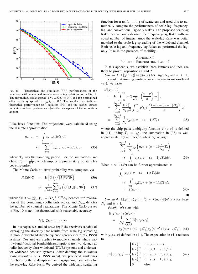
Fig. 10. Theoretical and simulated BER performances of thereceivers with scale- and translation-spacing relations as in Fig. 9.The normalized scale spread is γmaxTbfo = 0.1, and the normalizedeffective delay spread is τsupfo = 0.5. The solid curves indicatetheoretical performance (c.f. equation (30)) and the dashed curvesindicate simulated performance (see the description of the simulationabove).
Rake basis functions. The projections were calculated usingthe discrete approximation
hm,n =∫
xm,n(t)r(t)dt
≈Nsamps−1∑
i=0
xm,n(iTs)r(iTs)Ts, (35)
where Ts was the sampling period. For the simulations, wechose Ts = 1
15fo, which implies approximately 30 samples
per chip-pulse.The Monte-Carlo bit error probability was computed via
Pe(SNR) := E[Q(√
‖f‖2SNR)]
(36)
≈ 1Nsim
Nsim∑a=1
Q(√
‖fa‖2SNR)
(37)
where SNR := Eb
σ2w
, fa := (R−1/2x )Hha denotes ath realiza-
tion of the combining coefficients vector, and Nsim denotesthe number of channel realizations. The Monte Carlo curvesin Fig. 10 match the theoretical with reasonable accuracy.
VI. CONCLUSIONS
In this paper, we studied scale-lag Rake receivers capable ofleveraging the diversity that results from scale-lag spreadingin mobile wideband direct-sequence spread-spectrum (DSSS)systems. Our analysis applies to mobile channels where nar-rowband fractional-bandwidth assumptions are invalid, such asradio-frequency ultra-wideband (UWB) systems and underwa-ter wideband acoustic systems. After defining the minimumscale resolution of a DSSS signal, we produced guidelinesfor choosing the scale-spacing and lag-spacing parameters forthe scale-lag Rake basis. We derived the wideband scattering
function for a uniform ring of scatterers and used this to nu-merically compute the performances of scale-lag, frequency-lag, and conventional lag-only Rakes. The proposed scale-lagRake receiver outperformed the frequency-lag Rake with anequal number of fingers, since the scale-lag Rake was bettermatched to the scale-lag spreading of the wideband channel.Both scale-lag and frequency-lag Rakes outperformed the lag-only Rake in the presence of mobility.
APPENDIX IPROOF OF PROPOSITION 1 AND 2
In this appendix, we establish three lemmas and then usethem to prove Propositions 1 and 2.
Lemma 3: E[χ(a, τ)] ≈ χ(a, τ) for large Np and a ≈ 1.Proof: Assuming unit-variance zero-mean uncorrelated
{ci}, we write
E [χ(a, τ)]
= E[∫ ∞
−∞x(t)
1√ax
(t − τ
a
)dt
],
=Np−1∑i=0
E[c2i ]
Np√
a
∫ ∞
−∞p(t)p
(t − τ − (a − 1)iTo
a
)dt.
=Np−1∑i=0
1Np
χp (a, τ + (a − 1)iTo) (38)
where the chip pulse ambiguity function χp(a, τ) is definedin (11). Using To = Tb
Np, the summation in (38) is well
approximated by an integral when Np is large:Np−1∑i=0
1Np
χp
(a, τ + (a − 1)
i
NpTb
)
≈∫ 1
0
χp(a, τ + (a − 1)zTb)dz. (39)
When a ≈ 1, (39) can be further approximated as∫ 1
0
χp(a, τ + (a − 1)zTb)dz
≈∫ 1
0
χp(1, τ + (a − 1)zTb)dz,
= χ(a, τ). (40)
Lemma 4: E[χ(a, τ)χ(a′, τ ′)] ≈ χ(a, τ)χ(a′, τ ′) for largeNp and a ≈ 1.
Proof: We start with
E[χ(a, τ)χ(a′, τ ′)]
=1
N2p
∑i,j,k,l
E[cicjckcl]
χp(a, τ+(ai−j)To)χp(a′, τ ′+(a′k−l)To), (41)
with χp(a, τ) defined in (11). The expectation in (41) reducesto
E[cicjckcl] =
⎧⎪⎪⎪⎪⎪⎪⎨⎪⎪⎪⎪⎪⎪⎩
E[c4i ] i = j = k = l,
E[c2i ]
2 i = j, k = l, i �= k,
E[c2i ]
2 i = k, j = l, i �= j,
E[c2i ]
2 i = l, j = k, i �= j,
0 else.
. (42)
4318 IEEE TRANSACTIONS ON WIRELESS COMMUNICATIONS, VOL. 6, NO. 12, DECEMBER 2007
Using To = Tb
Np, we shall see that only the second case in (42)
yields a non-negligible contribution.The terms in (41) corresponding to {i = j = k = l} can
be upper bounded by
Np−1∑i=0
E[c4i ]
N2p
∣∣∣∣χp
(a, τ+(a − 1)
i
NpTb
)
χp
(a′, τ ′+(a′ − 1)
i
NpTb
)∣∣∣∣ ≤ E[c4i ]
Np, (43)
where the inequality in (43) follows from the chip pulse havingbounded energy, i.e., |χp(a, τ)| ≤ 1. Note that, for large Np,(43) becomes negligible. Next, the summation terms in (41)corresponding to {i = j, k = l, i �= k} can be approximated,for large Np as
∑i,k �=i
E[c2i ]
2
N2p
χp
(a, τ+(a − 1)
i
NpTb
)
χp
(a, τ ′+(a′ − 1)
k
NpTb
)
≈ E[c2i ]∫ 1
0
χp(1, τ + (a − 1)zTb)dz
E[c2i ]∫ 1
0
χp(1, τ ′ + (a′ − 1)z′Tb)dz′
= χ(a, τ)χ(a′, τ ′), (44)
while those corresponding to {i = k, j = l, i �= j} can beapproximated, for a ≈ 1, by
∑i,j �=i
E[c2i ]
2
N2p
∣∣∣∣χp (a, τ+(ai − j)To)
χp (a′, τ ′+(a′i − j)To)∣∣∣∣
≈∑i,j
E[c2i ]
2
N2p
∣∣∣∣χp (1, τ+(ai − j)To)
χp (1, τ ′+(a′i − j)To)∣∣∣∣ (45)
≤Np−1∑i=0
2 E[c2i ]
2
N2p
=2 E[c2
i ]2
Np. (46)
The following arguments justify (46). Since p(t) is time-limited to Tp seconds, χp(1, z) is non-zero only when |z| <Tp. Therefore, fixing a and τ , for each i ∈ {1, 2, . . . , Np−1},there are at most two values of j such that | τ
To+ai− j| < Tp
To.
This property, combined with |χp(a, τ)| < 1, leads to theinequality in (46). Note that, for large Np, the componentin (46) becomes negligible. Finally, the summation terms in(41) corresponding to {i = l, j = k, i �= j} can also beshown to negligible using similar arguments. In summary,only (44) yields a non-negligible contribution to (41), so thatE[χ(a, τ)χ(a′, τ ′)] ≈ χ(a, τ)χ(a′, τ ′).
Lemma 5: For Np large and a near unity, the widebandambiguity function χ(a, τ) is approximately equal to χ(a, τ)in the mean-squared sense.
Proof: Lemmas 3 and 4 imply
E[|χ(a, τ) − χ(a, τ)|2]= E[(χ(a, τ))2]−2 E[χ(a, τ)]χ(a, τ)+(χ(a, τ))2
≈ 0. (47)
A. Proposition 1
Proof: From Lemma 5, we see that χ(1, τ) is a mean-square approximation of χ(1, τ); hence, from (10)
χ(1, τ) ≈∫ 1
0
χp(1, τ)dz (48)
= χp(1, τ). (49)
The function χp(1, τ) = 0 when τ > Tp.
B. Proposition 2
Proof: From Lemma 5, we see that χ(a, 0) is a mean-square approximation of χ(a, 0); hence, from (10)
χ(a, 0) ≈∫ 1
0
χp(1, (a − 1)zTb)dz (50)
=∫ 1
0
Rp((a − 1)zTb)dz (51)
=1
2(a − 1)Tb
∫ (a−1)Tb
−(a−1)Tb
Rp(z)dz. (52)
where Rp(τ) := χp(1, τ) is the deterministic autocorrelationfunction of the chip pulse p(t). Suppose Sp(0) = 0 whereSp(f) is the energy spectral density of the chip pulse. Sincethe chip pulse has time support of Tp seconds, then for (a −1)Tb ≥ Tp ⇔ a ≥ 1 + Tp
Tbwe have
χ(a, τ) ≈ Sp(0) = 0,
for Np large and a near unity.
APPENDIX IIREAL-VALUED FREQUENCY-LAG BASIS
The real-valued frequency-lag basis is a simple modificationof the work in [15], which is included here to facilitatecomparison to our baseband scale-lag Rake. The frequency-lag basis functions are uniform frequency- and time-shiftedversions of the DSSS waveform:
xm,n(t) := ym(t/Tb)x(t − nto) (53)
where
ym(t) :=
⎧⎪⎨⎪⎩√
2 cos (2πmt) m > 0,
−√2 sin (2πmt) m < 0,
1 m = 0.
(54)
In [15], it is shown that the baud-spaced complex-valuedextension of the frequency-lag basis (53) is approximatelyorthonormal, which motivated using the frequency-lag Rakereceiver to extract diversity in doubly-spread narrowbandbaseband-equivalent channels.
MARGETTS et al.: JOINT SCALE-LAG DIVERSITY IN WIDEBAND MOBILE DIRECT SEQUENCE SPREAD SPECTRUM SYSTEMS 4319
REFERENCES
[1] J. Taylor, “Ultrawideband radar,” IEEE MTT-S International MicrowaveSymposium Digest, vol. 1, pp. 367–370, June 1991.
[2] Federal Communications Commission, “Revision of part 15 of thecommission’s rules regarding ultra-wideband transmission systems, Firstreport and order,” ET Docket 98-153, FCC 02-48, pp. 1–118, Feb. 14,2002.
[3] R. Balan, H. V. Poor, S. Rickard, and S. Verdú, “Time-frequency andtime-scale canonical representations of doubly spread channels,” Proc.European Signal Processing Conf., Sep. 2004, pp. 445–448.
[4] J. Davies, S. Pointer, and S. Dunn, “Wideband acoustic communicationsdispelling narrowband myths,” in OCEANS 2000 MTS/IEEE Conf.Exhibition, Sep. 2000, vol. 1, pp. 377–384.
[5] M. Win and R. Scholtz, “Ultra-wide bandwidth time-hopping spread-spectrum impulse radio for wireless multiple-access communications,”IEEE Trans. Commun., vol. 48, pp. 679–689, Apr. 2000.
[6] G. Hariharan and A. M. Sayeed, “Minimum probability of error insparse wideband channels,” in Proc. Allerton Conf. Commun., Control,Computing, Sep. 2006.
[7] B. M. Sadler and A. Swami, “On the performance of episodic UWBand direct-sequence communication systems,” IEEE Trans. WirelessCommun., vol. 3, pp. 2246–2255, Nov. 2004.
[8] M. Antweiler, L. Bomer, and H.-D. Luke, “Perfect ternary arrays,” IEEETrans. Inform. Theory, vol. 36, pp. 696–705, May 1990.
[9] D. Wu, P. Spasojevic, and I. Seskar, “Ternary zero correlation zonesequences for multiple code UWB,” in Proc. Conf. Inform. Science Syst.,Mar. 2004, pp. 939–943.
[10] S. Rickard, “Time-frequency and time-scale representations of doublyspread channels,” PhD thesis, Princeton University, Nov. 2003.
[11] J. F. Kepler, T. P. Krauss, and S. Mukthavaram, “Delay spread measure-ments on a wideband MIMO channel at 3.7 GHz,” in Proc. IEEE Veh.Technol. Conf., Sep. 2002, pp. 2498–2502.
[12] J. Proakis, Digital Communications, 4th ed. New York: McGraw-Hill,2001.
[13] M. Stojanovic, “Recent advances in high-speed underwater acousticcommunications,” IEEE J. Oceanic Engineering, vol. 21, pp. 125–136,Apr. 1996.
[14] L. Yang and G. B. Giannakis, “Ultra-wideband communications: Anidea whose time has come,” IEEE Signal Processing Mag., pp. 26–55,Nov. 2004.
[15] A. M. Sayeed and B. Aazhang, “Joint multipath-Doppler diversityin mobile wireless communications,” IEEE Trans. Commun., vol. 47,pp. 123–132, Jan. 1999.
[16] Y. Jiang and A. Papandreou-Suppappola, “Time-scale cononical modelfor wideband system characterization,” in Proc. IEEE Int. Conf.Acoustics, Speech, Signal Processing, Mar. 2005, pp. 281–284.
[17] Q. Jin, K. M. Wong, and Z.-Q. Luo, “The estimation of time delay andDoppler stretch of wideband signals,” IEEE Trans. Signal Processing,vol. 43, pp. 904–916, Apr. 1995.
[18] A. Swami, B. Sadler, and J. Turner, “On the coexistence of ultra-wideband and narrowband radio systems,” in Proc. IEEE MilitaryCommun. Conf., Oct. 2001, vol. 1, pp. 16–19.
[19] J. Conroy, J. LoCicero, and D. Ucci, “Communication techniques usingmonopulse waveforms,” in Proc. IEEE Military Commun. Conf., Oct1999, vol. 2, pp. 1181–1185.
[20] L. Zhao and A. Haimovich, “Performance of ultra-wideband communi-cations in the presence of interference,” IEEE J. Select. Areas Commun.,vol. 20, pp. 1684–1691, Dec. 2002.
[21] A. R. Margetts, “Joint scale-lag diversity in mobile wideband commu-nications,” PhD thesis, The Ohio State University, 2005.
[22] S. Mallat, A Wavelet Tour of Signal Processing, 2nd ed. San Diego:Academic Press, 1999.
[23] M. K. Tsatsanis and G. B. Giannakis, “Time-varying system iden-tification and model validation using wavelets,” IEEE Trans. SignalProcessing, vol. 41, pp. 3512–3523, Dec. 1993.
[24] M. Martone, “Wavelet-based separating kernels for sequence estimationwith unknown rapidly time-varying channels,” IEEE Commun. Lett.,vol. 3, pp. 78–80, Mar. 1999.
[25] L. G. Weiss, “Wavelets and wideband correlation processing,” IEEESignal Processing Mag., pp. 13–32, Jan. 1994.
[26] F.-Y. Lin and J.-M. Liu, “Ambiguity functions of laser-based chaoticradar,” IEEE J. Quantum Electronics, vol. 40, pp. 1732–1738, Dec. 2004.
[27] A. Fuxjaeger and R. Iltis, “Acquisition of timing and Doppler-shiftin a direct-sequence spread-spectrum system,” IEEE Trans. Commun.,vol. 42, pp. 2870–2880, Oct. 1994.
[28] G. Kaiser, “Physical wavelets and radar: A variational approach toremote sensing,” IEEE Antennas Propagat. Mag., vol. 38, pp. 15–24,Feb. 1996.
[29] M. Dawood and R. Narayanan, “Generalised wideband ambiguity func-tion of a coherent ultrawideband random noise radar,” IEE Radar, SonarNavigation, vol. 150, pp. 379–386, Oct. 2003.
[30] R. Scholtz and J.-Y. Lee, “Problems in modeling UWB channels,” inProc. Asilomar Conf. Signals, Syst., Computers, vol. 1, pp. 706–711,Nov. 2002.
[31] J.-Y. Lee and R. A. Scholtz, “Ranging in dense multipath environmentusing an UWB radio link,” IEEE J. Select. Areas Commun., vol. 20,pp. 1677–1683, Dec. 2002.
[32] J. Ovarlez, “Cramer-Rao bound computation for velocity estimation inthe broad band case using the mellin transform,” in Proc. IEEE Int.Conf. Acoust., Speech, Signal Processing, Apr. 1993, pp. 273–276.
[33] J. Bartrand, P. Bertrand, and J.-P. Ovarlez, The Transforms and Appli-cations Handbook, 2nd ed., ch. 11, pp. 1–11. CRC Press LLC, 2000.
[34] M. Terri, A. Hong, G. Guibe, and F. Legrand, “Major characteristics ofUWB indoor transmission for simulation,” in Proc. IEEE Veh. Technol.Conf., vol. 1, pp. 19–23, Apr. 2003.
[35] G. L. Stuber, Principles of Mobile Communications. Norwell, MA:Kluwer Academic, 1996.
[36] W. Jakes, Microwave Mobile Communications. Piscataway, NJ: IEEEPress, 1993.
[37] R. Narasimhan, “Finite-SNR diversity-multiplexing tradeoff for cor-related Rayleigh and Rician MIMO channels,” IEEE Trans. Inform.Theory, vol. 52, pp. 3965–3979, Sep. 2006.
Adam R. Margetts received a dual B.S. degree inElectrical Engineering and Mathematics from UtahState University, Logan, UT in 2000; and the M.S.and Ph.D. degrees in Electrical Engineering fromThe Ohio State University, Columbus, OH in 2002and 2005, respectively. Dr. Margetts is currently withMIT Lincoln Laboratory, Lexington, MA, and hisresearch interests include adaptive filtering, ultra-wideband and MIMO communications, and wirelessnetworking.
Philip Schniter received the B.S. and M.S. degreesin Electrical and Computer Engineering from theUniversity of Illinois at Urbana-Champaign in 1992and 1993, respectively. From 1993 to 1996 he wasemployed by Tektronix Inc. in Beaverton, OR as asystems engineer. In 2000, he received the Ph.D.degree in Electrical Engineering from Cornell Uni-versity in Ithaca, NY. Subsequently, he joined theDepartment of Electrical and Computer Engineeringat The Ohio State University in Columbus, OH,where he is now an Associate Professor. In 2003, he
received the National Science Foundation CAREER Award, and he currentlyserves on the IEEE Signal Processing for Communications Technical Commit-tee. Dr. Schniter’s research interests include signal processing, communicationtheory, and wireless networks.
Ananthram Swami received the B.Tech. degreefrom IIT, Bombay; the M.S. degree from RiceUniversity, Houston; and the Ph.D. degree from theUniversity of Southern California (USC), all in Elec-trical Engineering. He has held positions with Uno-cal Corporation, USC, CS-3 and Malgudi Systems.He was a Statistical Consultant to the CaliforniaLottery, developed a Matlab-based toolbox for non-Gaussian signal processing, and has held visitingfaculty positions at INP, Toulouse. He is currentlywith the US Army Research Laboratory where his
work is in the broad area of signal processing, wireless communications andnetworking, including both sensor networks and MANETs.