43iq instruction manual - thermo fisher scientific...introduction 43iq principle of operation thermo...
TRANSCRIPT

43iQ Instruction Manual
Sulfur Dioxide Analyzer117568-00 • 1Sep2019


Thermo Scientific 43iQ Instruction Manual iii
Contents Introduction ........................................................................................................ 1-1
iQ Series Instrument Platform............................................................. 1-1 43iQ Principle of Operation ............................................................... 1-3 Specifications ...................................................................................... 1-5 Dimensions ......................................................................................... 1-7
Installation and Setup ...................................................................................... 2-1 Unpacking and Inspection .................................................................. 2-1 Cover Removing and Replacing .......................................................... 2-2 Mounting Options .............................................................................. 2-3
Bench Mount ................................................................................... 2-3 Rack Mount ..................................................................................... 2-4
Setup Procedure .................................................................................. 2-6 Startup ................................................................................................ 2-8
Operation ............................................................................................................ 3-1 Instrument Display ............................................................................. 3-1
Main Menus and Keypads ................................................................ 3-5 Numeric Keypad ........................................................................... 3-6 Alphanumeric Keypad ................................................................... 3-7
Calibration .......................................................................................... 3-9 Calibrate Background ..................................................................... 3-11 Calibrate Span Coefficient ............................................................. 3-12 Zero/Span Schedule ....................................................................... 3-14 Advanced Calibration ..................................................................... 3-16
Manual Calibration ..................................................................... 3-17 Calibration History ..................................................................... 3-22
Data .................................................................................................. 3-23 View Data Log (Last Hour) ............................................................ 3-24 View Data Log (Last 24 Hours) ..................................................... 3-25 View Data Log (User Defined Time) ............................................. 3-26 Advanced Data Setup ..................................................................... 3-28
Data Logging Setup .................................................................... 3-29 Select Data Logging Variables ..................................................... 3-30 Streaming Data Setup ................................................................. 3-31 Select Streaming Variables ........................................................... 3-32
Settings ............................................................................................. 3-33 Health Check ................................................................................. 3-34
Chapter 1
Chapter 2
Chapter 3
Contents
iv 43iQ Instruction Manual Thermo Scientific
Status and Alarms........................................................................ 3-35 Valve and Pump Resets ............................................................... 3-46 Predictive Diagnostics ................................................................. 3-52 Maintenance ............................................................................... 3-53 Preventive Maintenance .............................................................. 3-54 Change Part ................................................................................ 3-56 Maintenance History................................................................... 3-57 File Sharing and Support ............................................................. 3-58 iQ360 ......................................................................................... 3-59
Measurement Settings .................................................................... 3-62 Averaging Time ........................................................................... 3-64 Range Mode Selection ................................................................. 3-66 Range Setting .............................................................................. 3-68 Gas Mode ................................................................................... 3-69 Gas Units .................................................................................... 3-70 Advanced Measurement Settings ................................................. 3-71
Communications ........................................................................... 3-77 Wired TCP/DHCP .................................................................... 3-79 Serial RS-232/485 ....................................................................... 3-81 Analog I/O .................................................................................. 3-82 Digital I/O .................................................................................. 3-83 Email Server (SMTP) .................................................................. 3-84 Bayern Hessen Settings ............................................................... 3-85
Instrument Settings ........................................................................ 3-87 Display Setup .............................................................................. 3-88 Alarm Setpoints ........................................................................... 3-89 Clock .......................................................................................... 3-92 Time Zone .................................................................................. 3-96
Configuration ................................................................................ 3-99 Security Access Levels ................................................................... 3-100
Change Security to View Only Access ....................................... 3-102 Change Full Access Security Password ....................................... 3-103
USB Drive ................................................................................... 3-105 Firmware Update Via USB Drive .............................................. 3-106 Download Data To USB Drive ................................................. 3-107 Change USB Password .............................................................. 3-110
User Contact Information ............................................................ 3-112 Update Bootloader ....................................................................... 3-113
Calibration .......................................................................................................... 4-1 Equipment Required ........................................................................... 4-1
Zero Air Generation ......................................................................... 4-2 Commercial Heatless Air Dryers ................................................... 4-2 Absorbing Column ........................................................................ 4-2
SO2 Concentration Standard ............................................................ 4-2 Calibration Gas Generation ............................................................. 4-2
Chapter 4

Contents
Thermo Scientific 43iQ Instruction Manual v
Cylinder Gas Dilution ................................................................... 4-3 External Flow Meter(s) and Controller(s) ...................................... 4-3 Commercial Precision Dilution Systems........................................ 4-4 Permeation Tube System............................................................... 4-4 Commercial Permeation Systems .................................................. 4-5
Calibration .......................................................................................... 4-6 Calibration in Dual/Auto Range Mode ............................................... 4-8 Zero and Span Check ........................................................................ 4-10 Manual Calibration ........................................................................... 4-11
Adjust Background ......................................................................... 4-12 Adjust Span Coefficient.................................................................. 4-12 Reset Bkg to 0.000 and Span Coef to 1.000 ................................... 4-13
Zero/Span Schedule .......................................................................... 4-14 Next Time ..................................................................................... 4-14 Period ............................................................................................ 4-14 Zero/Span/Purge Duration Minutes .............................................. 4-14 Schedule Averaging Time ............................................................... 4-15 Background Calibration and Span Calibration ............................... 4-15 Zero/Span Ratio ............................................................................. 4-15
References ......................................................................................... 4-15
Maintenance ...................................................................................................... 5-1 Safety Precautions ............................................................................... 5-1 Fan Filter Inspection and Cleaning ..................................................... 5-1 Pump Rebuilding ................................................................................ 5-2 Leak Test ............................................................................................ 5-5 Lamp Voltage Check ........................................................................... 5-6 Lamp Voltage Adjustment................................................................... 5-6
Troubleshooting ................................................................................................ 6-1 Safety Precautions ............................................................................... 6-1 Troubleshooting Guide ....................................................................... 6-1
Servicing ............................................................................................................. 7-1 Safety Precautions ............................................................................... 7-1 Firmware Updates ............................................................................... 7-3 Replacement Parts List ........................................................................ 7-3 Fuse Replacement ............................................................................... 7-5 Filter Replacement .............................................................................. 7-6 Fan Replacement ................................................................................. 7-7 Measurement Side Removal and Replacing ......................................... 7-9 LCD Module Replacement ............................................................... 7-12 I/O Replacement ............................................................................... 7-14 Peripherals Support Board and System Controller Board Replacement ..................................................................................... 7-16
Chapter 5
Chapter 6
Chapter 7

Contents
vi 43iQ Instruction Manual Thermo Scientific
DMC Pressure and Flow Board ........................................................ 7-17 Pump Replacement ........................................................................... 7-19 Capillary Cleaning and/or Replacement ............................................ 7-22 Capillary O-Ring Replacement ......................................................... 7-24 Power Supply Replacement ............................................................... 7-24 Step POL Board Replacement ........................................................... 7-26 DMC Optical Bench Removal .......................................................... 7-29
Optical Bench Assembly Removal .................................................. 7-29 Optical Bench Assembly Removal .................................................. 7-31 Photomultiplier Tube (PMT) Replacement ................................... 7-33 Flasher Pack Replacement .............................................................. 7-35 Flasher Pack Lamp Replacement .................................................... 7-36 Photo Lamp Detector Board Replacement ..................................... 7-37 Kicker Assembly Replacement ........................................................ 7-39
Optional Manifold Replacement ....................................................... 7-40 Optional DMC Permeation Oven Solenoid Valve Replacement ....... 7-42 Permeation Oven Replacement ......................................................... 7-44 Permeation Oven Board Replacement ............................................... 7-47
System Description ........................................................................................... 8-1 Optical Bench DMC........................................................................... 8-2
Heated Hydrocarbon Kicker ............................................................ 8-2 Optical Bench Hardware .................................................................. 8-2
Condensing Lens ........................................................................... 8-2 Mirror Assembly ........................................................................... 8-2 Light Baffle ................................................................................... 8-2 Bandpass Filter .............................................................................. 8-2
Flash Lamp Trigger Assembly .......................................................... 8-3 Flash Lamp ................................................................................... 8-3 Flash Trigger Board ....................................................................... 8-3 Flash Intensity Assembly ............................................................... 8-3
Photomultiplier Tube ...................................................................... 8-3 Optical Bench DMC Board ............................................................. 8-3
Bench Heater ................................................................................ 8-4 Permeation Oven (Optional) .............................................................. 8-4 Common Electronics .......................................................................... 8-4
Power Supply ................................................................................... 8-7 Front Panel ...................................................................................... 8-7 I/O and Communication Components ............................................ 8-7 System Controller Board .................................................................. 8-7 Backplane Board .............................................................................. 8-7
Peripherals Support System ................................................................. 8-8 Fan ................................................................................................... 8-8 STEP POL Board ............................................................................ 8-8 Sample Pump ................................................................................... 8-8 Solenoid Valve Panel ........................................................................ 8-8
Chapter 8
Contents
Thermo Scientific 43iQ Instruction Manual vii
Flow/Pressure DMC ........................................................................... 8-8 Firmware ............................................................................................. 8-8
Optional Equipment .......................................................................................... 9-1 Connecting External Devices .............................................................. 9-1
Communication Board .................................................................... 9-2 RS-232/RS-485 Port ..................................................................... 9-2 RS-485 External Accessory Port .................................................... 9-3
Analog I/O Board ............................................................................ 9-4 Analog Voltage Inputs ................................................................... 9-4 Analog Voltage Outputs ................................................................ 9-5
Analog Output Calibration .............................................................. 9-6 Analog Output Zero Calibration ................................................... 9-7 Analog Output Full Scale Calibration ........................................... 9-9
Digital I/O Board ........................................................................... 9-11 Digital Inputs .............................................................................. 9-11 Digital Relay Switches ................................................................. 9-13 Valve Driver Outputs .................................................................. 9-15
Internal Zero/Span and Sample Valves .............................................. 9-17 Internal Permeation Span Source ...................................................... 9-17
Permeation Tube Installation ......................................................... 9-19 Computation of Concentrations .................................................... 9-22
PTFE Particulate Filter ..................................................................... 9-23 High Flow Option ............................................................................ 9-23
Safety, Warranty, and WEEE .......................................................................... A-1 Safety .................................................................................................. A-1
Safety and Equipment Damage Alerts .............................................. A-1 Warranty ............................................................................................. A-2 WEEE Compliance ............................................................................. A-4
WEEE Symbol ................................................................................. A-4
Quick Reference .............................................................................................. B-1 List of Figures ..................................................................................... B-1 List of Tables....................................................................................... B-3
GNU Lesser General Public License ............................................................. C-1 GNU Lesser General Public License ................................................... C-1
Chapter 9
Appendix A
Appendix B
Appendix C


Thermo Scientific 43iQ Instruction Manual 1-1
Chapter 1
Introduction
The Thermo Scientific™ 43iQ Sulfur Dioxide (SO2) utilizes pulsed fluorescence technology to measure the amount of sulphur dioxide in the air.
The pulsing of the UV source lamp serves to increase the optical intensity whereby a greater UV energy throughput and lower detectable SO2 concentration are realized.
Reflective bandpass filters, as compared to commonly used transmission filters, are less subject to photochemical degradation and more selective in wavelength isolation. This results in both increased detection specificity and long term stability.
The iQ Series Instrument Platform is a smart environmental monitoring solution for ambient and source gas analysis that affords greater control over instrument performance and data availability.
● Distributed Measurement and Control (DMC) module design simplifies serviceability. Each DMC module contains its own microprocessor control enabling functional performance validation at the module level.
● Built-in predictive diagnostics and preventive maintenance schedules identify problems before they occur. The iQ Series platform sends email notifications directly to Thermo Fisher Scientific’s world class service support team or locally identified addressees in order to proactively communicate analyzer performance conditions and identify spare parts needs before an operational concern arises.
● The iQ Series platform supports Modbus, streaming and VNC protocols over serial and Ethernet as well as analog and digital I/O for easy integration into most data management systems.
● Three standard USB ports afford convenient data download capability as well as the ability to connect additional hardware, such as a computer keyboard or mouse.
● The iQ Series GUI runs on a 7” color touchscreen display. The GUI is highly flexible and can be customized to enable a tailored
iQ SeriesInstrument
Platform
Introduction iQ Series Instrument Platform
1-2 43iQ Instruction Manual Thermo Scientific
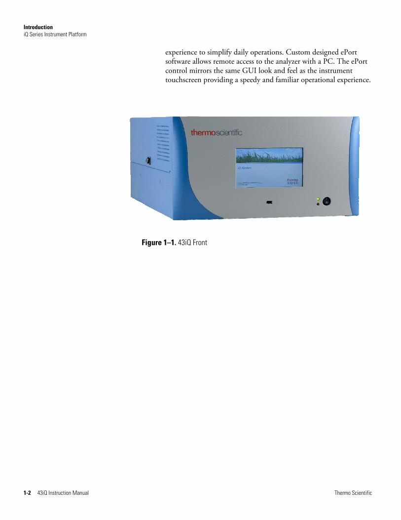
experience to simplify daily operations. Custom designed ePort software allows remote access to the analyzer with a PC. The ePort control mirrors the same GUI look and feel as the instrument touchscreen providing a speedy and familiar operational experience.
Figure 1–1. 43iQ Front

Introduction 43iQ Principle of Operation
Thermo Scientific 43iQ Instruction Manual 1-3
The 43iQ operates on the principle that SO2 molecules absorb ultraviolet (UV) light and become excited at one wavelength, then decay to a lower energy state emitting UV light at a different wavelength. Specifically,
2 2212 hSO*SOh SO
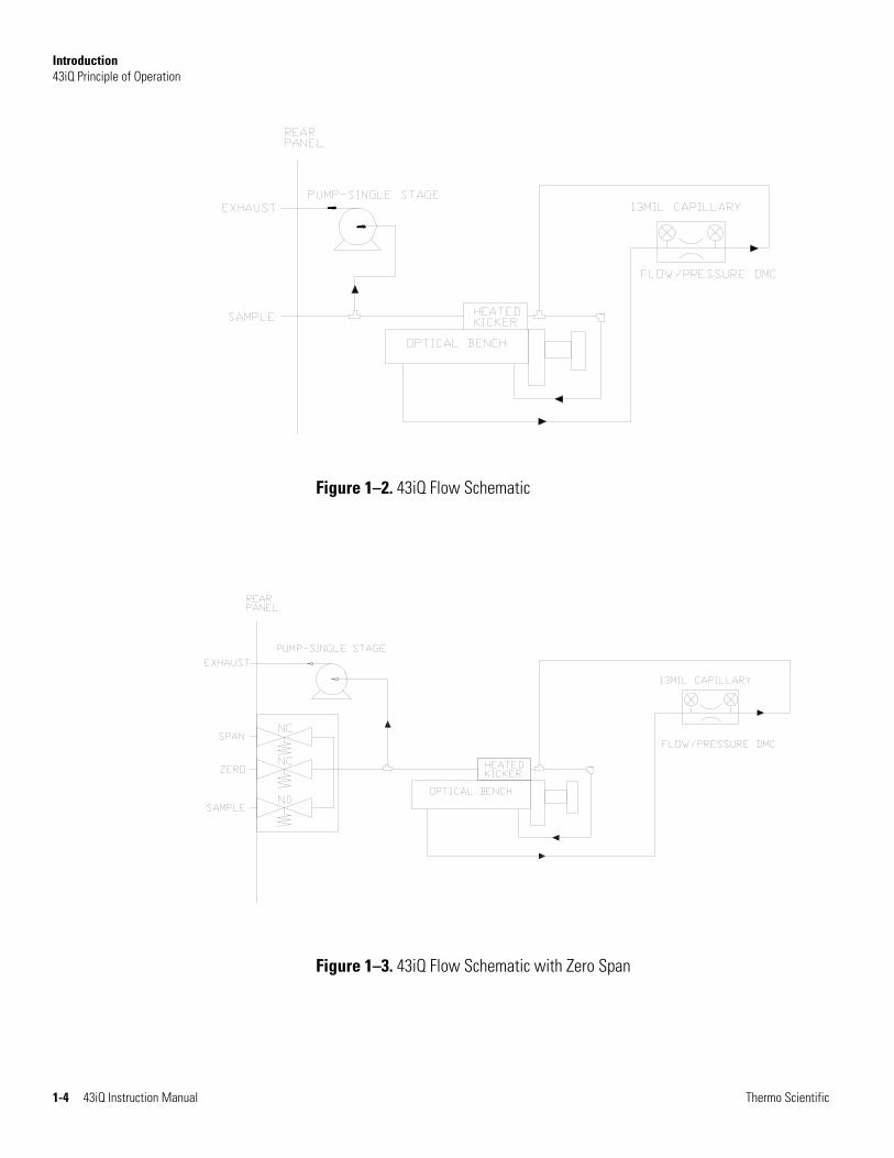
The sample is drawn into the 43iQ through the SAMPLE bulkhead, as shown in Figure 1–2. The sample flows through a hydrocarbon “kicker,” which removes hydrocarbons from the sample by forcing the hydrocarbon molecules to permeate through the tube wall. The SO2 molecules pass through the hydrocarbon “kicker” unaffected.
The sample then flows into the fluorescence chamber, where pulsating UV light excites the SO2 molecules. The condensing lens focuses the pulsating UV light into the mirror assembly. The mirror assembly contains four selective mirrors that reflect only the wavelengths which excite SO2 molecules.
As the excited SO2 molecules decay to lower energy states they emit UV light that is proportional to the SO2 concentration. The bandpass filter allows only the wavelengths emitted by the excited SO2 molecules to reach the photomultiplier tube (PMT). The PMT detects the UV light emission from the decaying SO2 molecules. The photodetector, located at the back of the fluorescence chamber, continuously monitors the pulsating UV light source and is connected to a circuit that compensates for fluctuations in the UV light.
As the sample leaves the optical chamber, it passes through a flow sensor, a capillary, and the “shell” side of the hydrocarbon kicker. The sample then flows to the pump and is exhausted out the EXHAUST bulkhead of the analyzer. The 43iQ outputs the SO2 concentration to the front panel display and the analog outputs, and also makes the data available over the serial or Ethernet connection.
43iQ Principle of Operation
Introduction 43iQ Principle of Operation
1-4 43iQ Instruction Manual Thermo Scientific
Figure 1–2. 43iQ Flow Schematic
Figure 1–3. 43iQ Flow Schematic with Zero Span
Introduction Specifications
Thermo Scientific 43iQ Instruction Manual 1-5
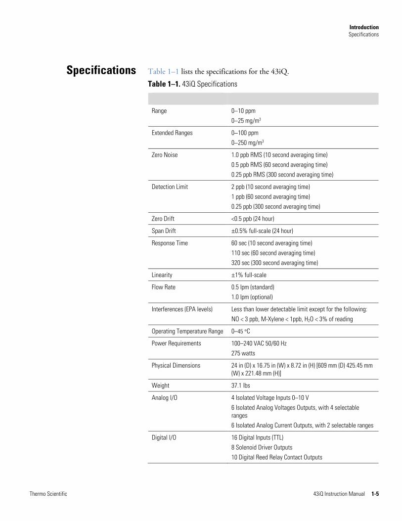
Table 1–1 lists the specifications for the 43iQ.
Table 1–1. 43iQ Specifications
Range 010 ppm 025 mg/m3
Extended Ranges 0100 ppm 0250 mg/m3
Zero Noise 1.0 ppb RMS (10 second averaging time) 0.5 ppb RMS (60 second averaging time) 0.25 ppb RMS (300 second averaging time)
Detection Limit 2 ppb (10 second averaging time) 1 ppb (60 second averaging time) 0.25 ppb (300 second averaging time)
Zero Drift <0.5 ppb (24 hour)
Span Drift ±0.5% full-scale (24 hour)
Response Time 60 sec (10 second averaging time) 110 sec (60 second averaging time) 320 sec (300 second averaging time)
Linearity ±1% full-scale
Flow Rate 0.5 lpm (standard) 1.0 lpm (optional)
Interferences (EPA levels) Less than lower detectable limit except for the following: NO < 3 ppb, M-Xylene < 1ppb, H2O < 3% of reading
Operating Temperature Range 0–45 °C
Power Requirements
100–240 VAC 50/60 Hz 275 watts
Physical Dimensions 24 in (D) x 16.75 in (W) x 8.72 in (H) [609 mm (D) 425.45 mm (W) x 221.48 mm (H)]
Weight 37.1 lbs
Analog I/O 4 Isolated Voltage Inputs 0–10 V 6 Isolated Analog Voltages Outputs, with 4 selectable ranges 6 Isolated Analog Current Outputs, with 2 selectable ranges
Digital I/O 16 Digital Inputs (TTL) 8 Solenoid Driver Outputs 10 Digital Reed Relay Contact Outputs
Specifications
Introduction Specifications
1-6 43iQ Instruction Manual Thermo Scientific
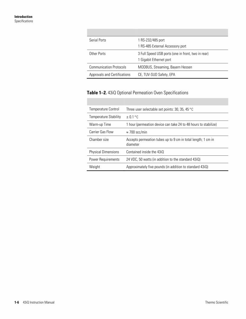
Serial Ports 1 RS-232/485 port 1 RS-485 External Accessory port
Other Ports 3 Full Speed USB ports (one in front, two in rear) 1 Gigabit Ethernet port
Communication Protocols MODBUS, Streaming, Bayern Hessen
Approvals and Certifications CE, TUV-SUD Safety, EPA
Table 1–2. 43iQ Optional Permeation Oven Specifications
Temperature Control Three user selectable set points: 30, 35, 45 C
Temperature Stability ± 0.1 C
Warm-up Time 1 hour (permeation device can take 24 to 48 hours to stabilize)
Carrier Gas Flow 700 scc/min
Chamber size Accepts permeation tubes up to 9 cm in total length; 1 cm in diameter
Physical Dimensions Contained inside the 43iQ
Power Requirements 24 VDC, 50 watts (in addition to the standard 43iQ)
Weight Approximately five pounds (in addition to standard 43iQ)
Introduction Dimensions
Thermo Scientific 43iQ Instruction Manual 1-7
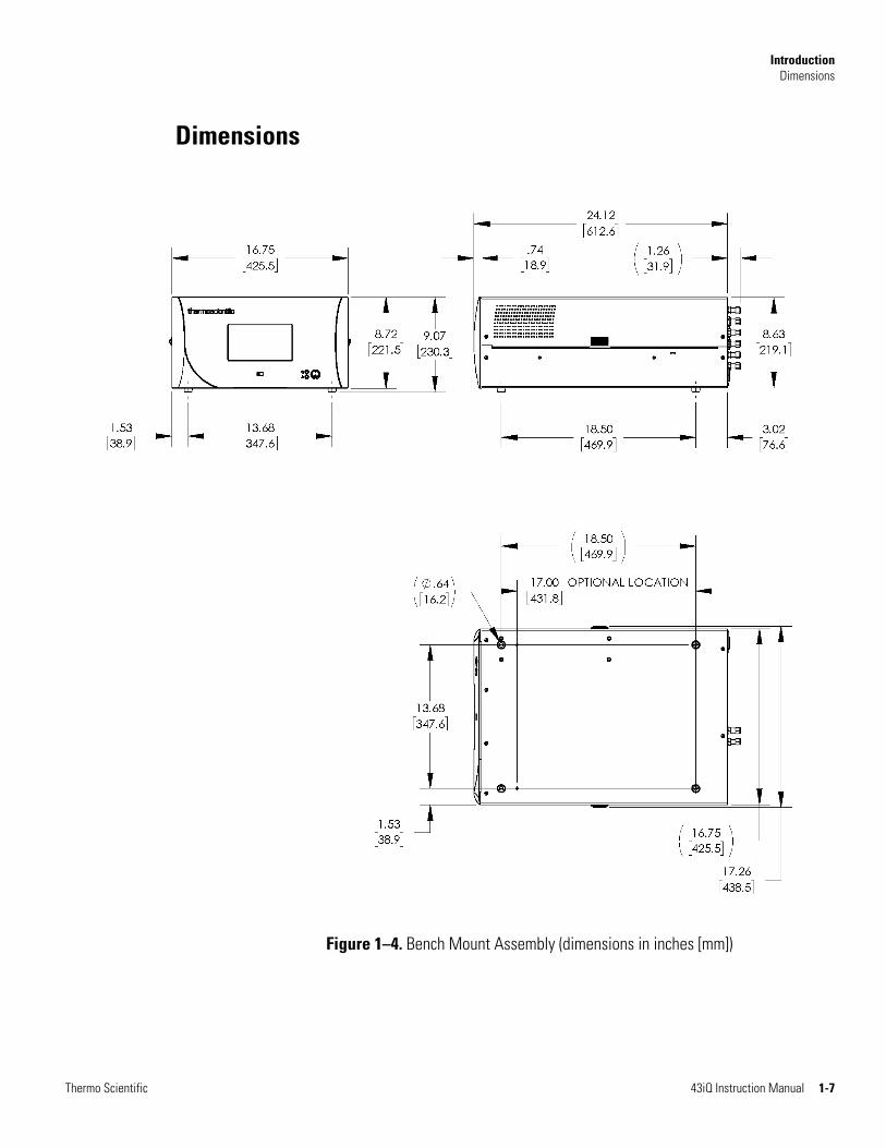
Figure 1–4. Bench Mount Assembly (dimensions in inches [mm])
Dimensions
Introduction Dimensions
1-8 43iQ Instruction Manual Thermo Scientific
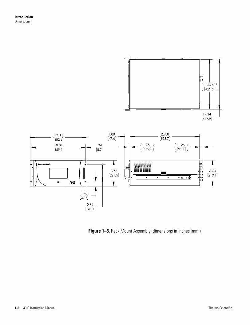
Figure 1–5. Rack Mount Assembly (dimensions in inches [mm])
Introduction Dimensions
Thermo Scientific 43iQ Instruction Manual 1-9
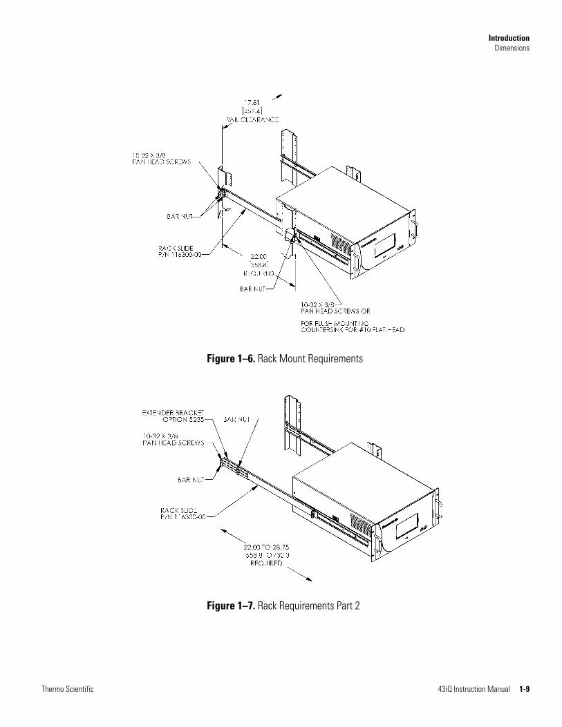
Figure 1–6. Rack Mount Requirements
Figure 1–7. Rack Requirements Part 2


Thermo Scientific 43iQ Instruction Manual 2-1
Chapter 2
Installation and Setup
Installation and Setup describes how to unpack, setup, and start-up the instrument. The installation should always be followed by instrument calibration as described in the “Calibration” chapter of this manual.
Equipment Damage Do not attempt to lift the instrument by the cover or other external fittings. ▲
The 43iQ is shipped complete in one container. If there is obvious damage to the shipping container when you receive the instrument, notify the carrier immediately and hold for inspection. The carrier is responsible for any damage incurred during shipment.
Use the following procedure to unpack and inspect the instrument.
1. Remove the instrument from the shipping container and set it on a table or bench that allows easy access to both the front and rear.
2. Remove the cover to expose the internal components. (See “Figure 2–1” on page 2-2.)
3. Check for possible damage during shipment.
4. Check that all connectors and circuit boards are firmly attached.
5. Re-install the cover.
6. Remove any protective plastic material from the case exterior.
Unpacking andInspection
Installation and Setup Cover Removing and Replacing
2-2 43iQ Instruction Manual Thermo Scientific
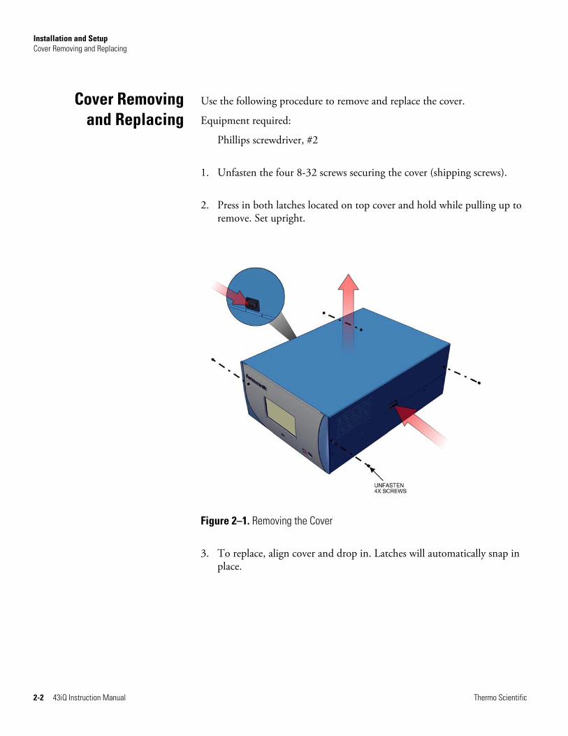
Use the following procedure to remove and replace the cover.
Equipment required:
Phillips screwdriver, #2
1. Unfasten the four 8-32 screws securing the cover (shipping screws).
2. Press in both latches located on top cover and hold while pulling up to remove. Set upright.
Figure 2–1. Removing the Cover
3. To replace, align cover and drop in. Latches will automatically snap in place.
Cover Removingand Replacing
Installation and Setup Mounting Options
Thermo Scientific 43iQ Instruction Manual 2-3
The instrument can be installed in the following configurations:
● Bench Mount
● Rack Mount
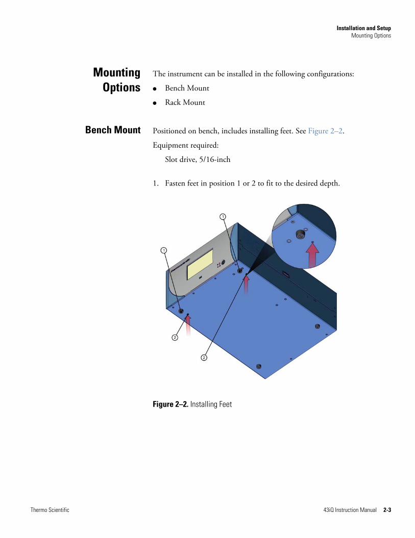
Positioned on bench, includes installing feet. See Figure 2–2.
Equipment required:
Slot drive, 5/16-inch
1. Fasten feet in position 1 or 2 to fit to the desired depth.
Figure 2–2. Installing Feet
MountingOptions
Bench Mount
Installation and Setup Mounting Options
2-4 43iQ Instruction Manual Thermo Scientific
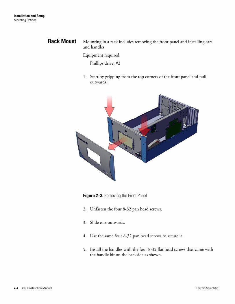
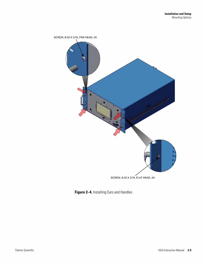
Mounting in a rack includes removing the front panel and installing ears and handles.
Equipment required:
Phillips drive, #2
1. Start by gripping from the top corners of the front panel and pull outwards.
Figure 2–3. Removing the Front Panel
2. Unfasten the four 8-32 pan head screws.
3. Slide ears outwards.
4. Use the same four 8-32 pan head screws to secure it.
5. Install the handles with the four 8-32 flat head screws that came with the handle kit on the backside as shown.
Rack Mount
Installation and Setup Mounting Options
Thermo Scientific 43iQ Instruction Manual 2-5
Figure 2–4. Installing Ears and Handles
Installation and Setup Setup Procedure
2-6 43iQ Instruction Manual Thermo Scientific
Use the following procedure to setup the instrument:
1. Connect the sample line to the SAMPLE bulkhead on the rear panel (Figure 2–5). Ensure that the sample line is not contaminated by dirty, wet, or incompatible materials. All tubing should be constructed of PTFE, 316 stainless steel, borosilicate glass, or similar tubing with an OD of 1/4-inch and a minimum ID of 1/8-inch. The length of the tubing should be less than 10 feet.
Note Gas must be delivered to the instrument free of particulates. It may be necessary to use the PTFE particulate filter as described in “PTFE Particulate Filter” on page 9-23. ▲
Note If the sample may contain particulates larger than 5 microns, it should be filtered before introducing it to the instrument. Use a filter (such as PTFE) that does not interact with SO2 in the sample. If a sample filter is used, all calibrations and span checks must be performed through the filter. The filter element should be replaced regularly to prevent the absorption of SO2 by trapped material on the filter. ▲
Note Gas must be delivered to the instrument at atmospheric pressure. It may be necessary to use an atmospheric bypass plumbing arrangement as shown in Figure 2–6 if gas pressure is greater than atmospheric pressure. ▲
2. Connect the EXHAUST bulkhead to a suitable vent. The exhaust line should be 1/4-inch OD with a minimum ID of 1/8-inch. The length of the exhaust line should be less than 10 feet. Verify that there is no restriction in this line.
3. If the optional zero/span solenoid valves are installed, connect a source of SO2 and HC free air to the ZERO IN bulkhead, and connect a source of SO2 span gas to the SPAN bulkhead.
4. Connect a suitable recording device to the rear panel connector. For detailed information about connecting to the instrument, refer to:
“Connecting External Devices” on page 9-1
Communications > “Analog I/O” on page 3-82, and “Digital I/O” on page 3-83.
Setup Procedure

Installation and Setup Setup Procedure
Thermo Scientific 43iQ Instruction Manual 2-7
5. Plug the instrument into an outlet of the appropriate voltage and frequency.
Note If instrument is equipped with an internal permeation oven, refer to Chapter 9, “Optional Equipment” for setup instructions. ▲
The 43iQ is supplied with a three-wire grounding cord. Under no circumstances should this grounding system be defeated. ▲
Figure 2–5. 43iQ Rear Panel
Figure 2–6. Atmospheric Dump Bypass Plumbing
Icon Here

Installation and Setup Startup
2-8 43iQ Instruction Manual Thermo Scientific
Use the following procedure when starting the instrument.
1. Turn the power ON.
2. Allow 90–120 minutes for the instrument to stabilize. During the time that the instrument is warming up, the mode “warm up” is displayed on the gas mode button in the title bar, and the concentration calculation is turned off. To disable warm up, go to Settings>Configuration.
3. Set instrument parameters such as operating ranges and averaging times to their appropriate settings. For more information about instrument parameters, see the “Operation” chapter.
4. Before beginning the actual monitoring, perform a calibration as described in the “Calibration” chapter.
Figure 2–7. Front Panel and Touchscreen Display
Startup

Thermo Scientific 43iQ Instruction Manual 3-1
Chapter 3
Operation
This chapter describes the functionality of the touchscreen user interface.
The Instrument Display consists of a Title Bar, a User Interface, and a Status Bar. The Title Bar, located at the top, includes the Home button, instrument name, instrument gas mode, and Help button. The User Interface, located in the middle, is where the Home Screen and all other screens are accessed. The Home Screen has three Main Menu buttons, located on the left side, which include Calibration, Data, and Settings, while the user interface to the right of the buttons displays the chemical name, concentration value and unit. The Status Bar, located at the bottom, includes the Back button, Access Levels, Health Check, Favorites, Date and Time, and Contact Information.
Home Screen (single range mode)
InstrumentDisplay
Title Bar
User Interface
Status Bar

Operation Instrument Display
3-2 43iQ Instruction Manual Thermo Scientific
Home Screen (dual or auto range mode)
Title Bar
User Interface
Status Bar

Operation Instrument Display
Thermo Scientific 43iQ Instruction Manual 3-3
The Instrument Display contains the following information:
● Title Bar:
● Home button: When pressed, it brings you to the Home Screen.
● Title Text: Displays instrument name when in the Home Screen. Displays the chemical name, current concentration reading and unit when in all other screens. When unit is pressed, it brings you to the gas unit selection screen.
● Gas Mode button: Displays current gas mode of the instrument. When pressed, brings you to the Gas Mode selection screen.
● Help button: When pressed, brings you to the help screens.
● User Interface:
● Calibration button: Allows the user to calibrate the instrument, setup automatic calibrations, and view calibration data.
● Data button: Allows the user to view, graph, stream, and analyze data.
● Settings button: Shows real-time status and alarms, also predictive diagnostics and maintenance history. Contains controls for operating the instrument, communications, and sets instrument options.
● Concentration: When in single mode, displays SO2 concentrations in big, bold characters, depending on operating mode. When in dual or auto mode, displays either high range or low range values based on the range setting.
● Status Bar:
● Back button: When pressed, it displays the previous screen.
● Access Levels button: Allows the user to set security access levels, and allows/restricts access to functionality depending on the selected access level.
● Health Check button: Brings the user to the Health Check screen.
● Favorites button: Allows user-selectable favorite buttons. To add to the favorites screen, user presses the desired screen button for 2 seconds. The user will be directed to the favorites screen where the user chooses the button position. To remove a favorite button from the favorites screen, press and hold button for 2 seconds.
● Clock: Displays current date and time.

Operation Instrument Display
3-4 43iQ Instruction Manual Thermo Scientific
● Thermo Scientific Information button: Shows contact information.

Operation Instrument Display
Thermo Scientific 43iQ Instruction Manual 3-5
The Main Menu buttons, located on the Home Screen, contains three submenus. Each submenu contains related instrument settings. This chapter describes each submenu and screen in detail. Refer to the appropriate sections for more information.
Calibration Data Settings
Calibrate Background
Advanced Calibration Manual Calibration
Adjust Background Adjust Span Coefficient Reset Bkg and Span Coef
Calibration History
Zero/Span Schedule
Measurement Settings Averaging Time Range Mode Selection Range Setting Gas Mode Gas Units Dilution Ratio Advanced Measurement
Optical Bench Settings Flash Lamp Optical Span Test Extended Ranges Compensation Perm Oven Settings
(Optional) Pressure Calibration
Instrument Settings Display Setup Alarm Setpoints Language Clock Pump Power Reboot Instrument
Communications
Configuration
Security Access Levels
USB Drive Firmware Update Via USB
Drive Download Data to USB Drive Change USB Password
User Contact Information
Calibrate Span Coefficient
Health Check Status and Alarms Predictive Diagnostics Maintenance File Sharing and Support iQ360 Firmware Version
Update Bootloader
Advanced Data Data Logging Setup Streaming Data Setup
View Data Log (Last Hour) Graph
View Data (User Defined Time) Start Time
End Time – View Data Graph
View Data Log (Last 24 Hours) Graph
Main Menus and Keypads
Operation Instrument Display
3-6 43iQ Instruction Manual Thermo Scientific
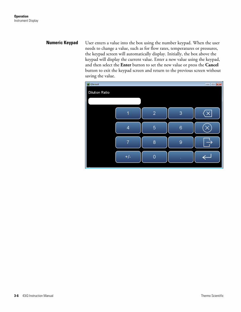
User enters a value into the box using the number keypad. When the user needs to change a value, such as for flow rates, temperatures or pressures, the keypad screen will automatically display. Initially, the box above the keypad will display the current value. Enter a new value using the keypad, and then select the Enter button to set the new value or press the Cancel button to exit the keypad screen and return to the previous screen without saving the value.
Numeric Keypad

Operation Instrument Display
Thermo Scientific 43iQ Instruction Manual 3-7
User enters a value into the box using the keypad. When the user needs to change an alphanumeric value, this keypad will automatically display. Initially, the box above the keypad will display the current value. Enter a new value using the keypad, and then select the Enter button to set the new value or press the Cancel button to exit the keypad screen and return to the previous screen without saving the value. The alphanumeric keypad is only available when the user needs to enter alphabet characters.
Alphanumeric Keypad

Operation Instrument Display
3-8 43iQ Instruction Manual Thermo Scientific

Operation Calibration
Thermo Scientific 43iQ Instruction Manual 3-9
The Calibration screen allows the user to calibrate the system, setup automatic calibrations, and view calibration data. See Chapter 4 “Calibration” for further instructions on how to run a calibration.
The following screens show the calibration screens in single range mode and dual or auto range mode. The dual and auto range modes have two SO2 span factors (high and low). This allows each range to be calibrated separately. This is necessary if the two ranges used are not close to one another. For example, a low SO2 range of .5 ppm and a high SO2 range of 10 ppm. For more information about range modes, see “Range Mode Selection” on page 3-66.
Home Screen>Calibration (single range mode)
Home Screen>Calibration (dual or auto range mode)
The Calibration screen contains the following information:
● Calibrate Background: Sets the SO2 reading to zero.
● Calibrate Span Coefficient: Sets the span coefficient when in single range mode.
Calibration

Operation Calibration
3-10 43iQ Instruction Manual Thermo Scientific
● Calibrate High Range Span Coefficient: Sets the high range span coefficient when in dual or auto range mode.
● Calibrate Low Range Span Coefficient: Sets the low range span coefficient when in dual or auto range mode.
● Zero/Span Schedule: Programs the instrument to perform fully automated zero and span checks or adjustments.
● Advanced Calibration: Calibrates the instrument using manual zero/span calibration and provides calibration history.

Operation Calibration
Thermo Scientific 43iQ Instruction Manual 3-11
The Calibrate Background screen is used to calibrate the instrument zero background. Before making an adjustment, be sure the analyzer samples zero air for at least 5 minutes.
It is important to note the averaging time when calibrating. The longer the averaging time the more precise the calibration results. To achieve maximum precision, allow the instrument to stabilize each time input gas is changed and set the averaging time to 300-second averaging.
Home Screen>Calibration>Calibrate Background
The Calibrate Background screen contains the following information:
● Target Concentration: Read only. Displays what the concentration value will become when the calibrate button is pressed.
● Current Background: Read only. Displays what the current user-set background is.
● Calculated Background: Read only. Displays what the current user-set background will become when the calibrate button is pressed.
● Calibrate: When pressed, updates the background value, setting the displayed concentration to zero.
Calibrate Background

Operation Calibration
3-12 43iQ Instruction Manual Thermo Scientific
The Calibrate Span Coefficient screen is used to enter the span concentration and calibrate the SO2 span coefficient. The SO2 span coefficient is calculated, stored, and used to correct the current reading.
The following screens are shown in single range mode and dual or auto range mode. In dual or auto range modes, “High” or “Low” is displayed to indicate the calibration of the high or low coefficient. The Calibrate High Range Span Coefficient and Calibrate Low Range Span Coefficient screens function the same way.
It is important to note the averaging time when calibrating. The longer the averaging time the more precise the calibration results. To achieve maximum precision, allow the instrument to stabilize each time input gas is changed and set the averaging time to 300-second averaging.
Home Screen>Calibration>Calibrate Span Coefficient (single range mode)
Home Screen>Calibration>Calibrate Span Coefficient (dual or auto range mode)
Calibrate SpanCoefficient

Operation Calibration
Thermo Scientific 43iQ Instruction Manual 3-13
The Calibrate Span Coefficient screen contains the following information:
● Edit Span Concentration: User enters the span gas concentration when in single range mode.
● Edit High Range Span Concentration: User enters the high range span concentration when in dual or auto range mode.
● Edit Low Range Span Concentration: User enters the low range span concentration when in dual or auto range mode.
● Current High Range Concentration: Read only. Current high range concentration reading when in dual or auto range mode.
● Current Low Range Concentration: Read only. Current low concentration reading when in dual or auto range mode.
● Current Span Coefficient: Read only. Displays the current instrument span coefficient.
● Current High Range Span Coefficient: Read only. Displays the current instrument high range span coefficient.
● Current Low Range Span Coefficient: Read only. Displays the current instrument low range span coefficient.
● Calculated Span Coefficient: Read only. After the “Edit Span Concentration” value is entered, the new calculated span coefficient is displayed.
● Calculated High Range Span Coefficient: Read only. After the “Edit High Range Span Concentration” value is entered, the new calculated high range span coefficient is displayed.
● Calculated Low Range Span Coefficient: Read only. After the “Edit Low Range Span Concentration” value is entered, the new calculated low range span coefficient is displayed.
● Calibrate: When pressed, updates the coefficient and the concentration should match the span concentration.
Operation Calibration
3-14 43iQ Instruction Manual Thermo Scientific
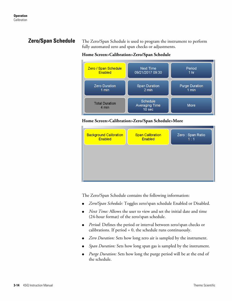
The Zero/Span Schedule is used to program the instrument to perform fully automated zero and span checks or adjustments.
Home Screen>Calibration>Zero/Span Schedule
Home Screen>Calibration>Zero/Span Schedule>More
The Zero/Span Schedule contains the following information:
● Zero/Span Schedule: Toggles zero/span schedule Enabled or Disabled.
● Next Time: Allows the user to view and set the initial date and time (24-hour format) of the zero/span schedule.
● Period: Defines the period or interval between zero/span checks or calibrations. If period = 0, the schedule runs continuously.
● Zero Duration: Sets how long zero air is sampled by the instrument.
● Span Duration: Sets how long span gas is sampled by the instrument.
● Purge Duration: Sets how long the purge period will be at the end of the schedule.
Zero/Span Schedule

Operation Calibration
Thermo Scientific 43iQ Instruction Manual 3-15
● Total Duration: Read only. Displays the total time duration of all scheduled events.
● Schedule Averaging Time: Allows the user to adjust the zero/span schedule averaging time. This averaging time only affects the zero/span schedule.
● Background Calibration: Toggles Enabled/Disabled. If enabled, background value is calibrated. If disabled, schedule runs a background check only and background value is not updated.
● Span Calibration: Toggles Enabled/Disabled. If enabled, span coefficient is calibrated. If disabled, schedule runs a calibration check only and span coefficient is not updated.
● Zero : Span Ratio: Allows the user to perform more scheduled background calibration checks to span calibration checks. Default is 1 and therefore reads 1:1. (This means that each time the schedule is run, both the zero duration and span duration occurs.) The zero/span ratio is allowable between 1 to 99. If 99 is chosen, the schedule should only perform the Span on the 99th iteration.
Operation Calibration
3-16 43iQ Instruction Manual Thermo Scientific
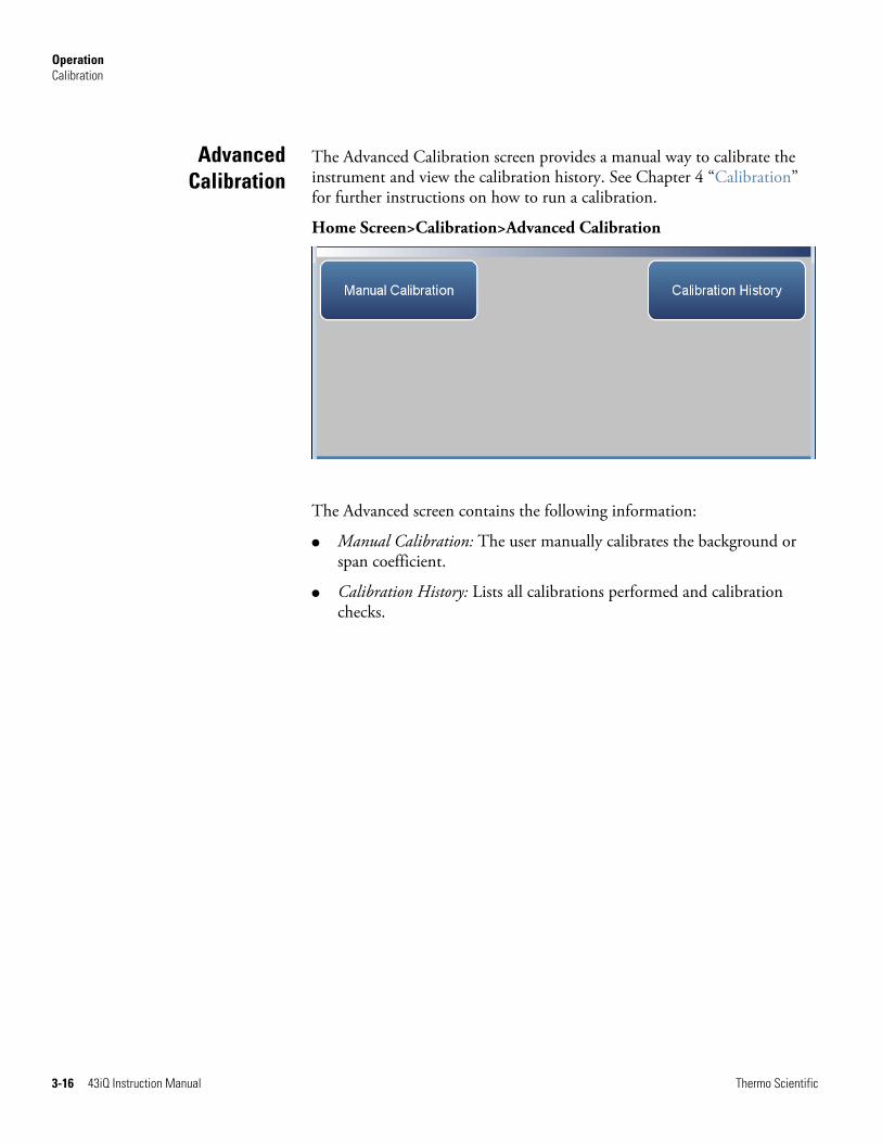
The Advanced Calibration screen provides a manual way to calibrate the instrument and view the calibration history. See Chapter 4 “Calibration” for further instructions on how to run a calibration.
Home Screen>Calibration>Advanced Calibration
The Advanced screen contains the following information:
● Manual Calibration: The user manually calibrates the background or span coefficient.
● Calibration History: Lists all calibrations performed and calibration checks.
AdvancedCalibration

Operation Calibration
Thermo Scientific 43iQ Instruction Manual 3-17
The Manual Calibration screen adjusts the zero background or span coefficient based on a user entered value. See Chapter 4, “Calibration” for instructions on how to run a Manual Calibration.
The following screens show the manual calibration screens in single range mode and dual or auto range mode. In dual or auto range modes, “High Range” or “Low Range” buttons are displayed to indicate the calibration of the high or low coefficient.
Home Screen>Calibration>Advanced Calibration>Manual Calibration (single range mode)
Home Screen>Calibration>Advanced Calibration>Manual Calibration (dual or auto range mode)
The Manual Calibration screen contains the following information:
● Adjust Background: Allows the user to manually adjust the zero background.
● Adjust Span Coefficient: Allows the user to manually adjust the span coefficient when in single range mode.
Manual Calibration

Operation Calibration
3-18 43iQ Instruction Manual Thermo Scientific
● Adjust High Range Span Coefficient: Allows the user to manually adjust the high range span coefficient when in dual or auto range mode.
● Adjust Low Range Span Coefficient: Allows the user to manually adjust the low range span coefficient when in dual or auto range mode.
● Reset Background to 0.000 and Span Coefficient to 1.000: Resets all backgrounds and coefficients.
Operation Calibration
Thermo Scientific 43iQ Instruction Manual 3-19
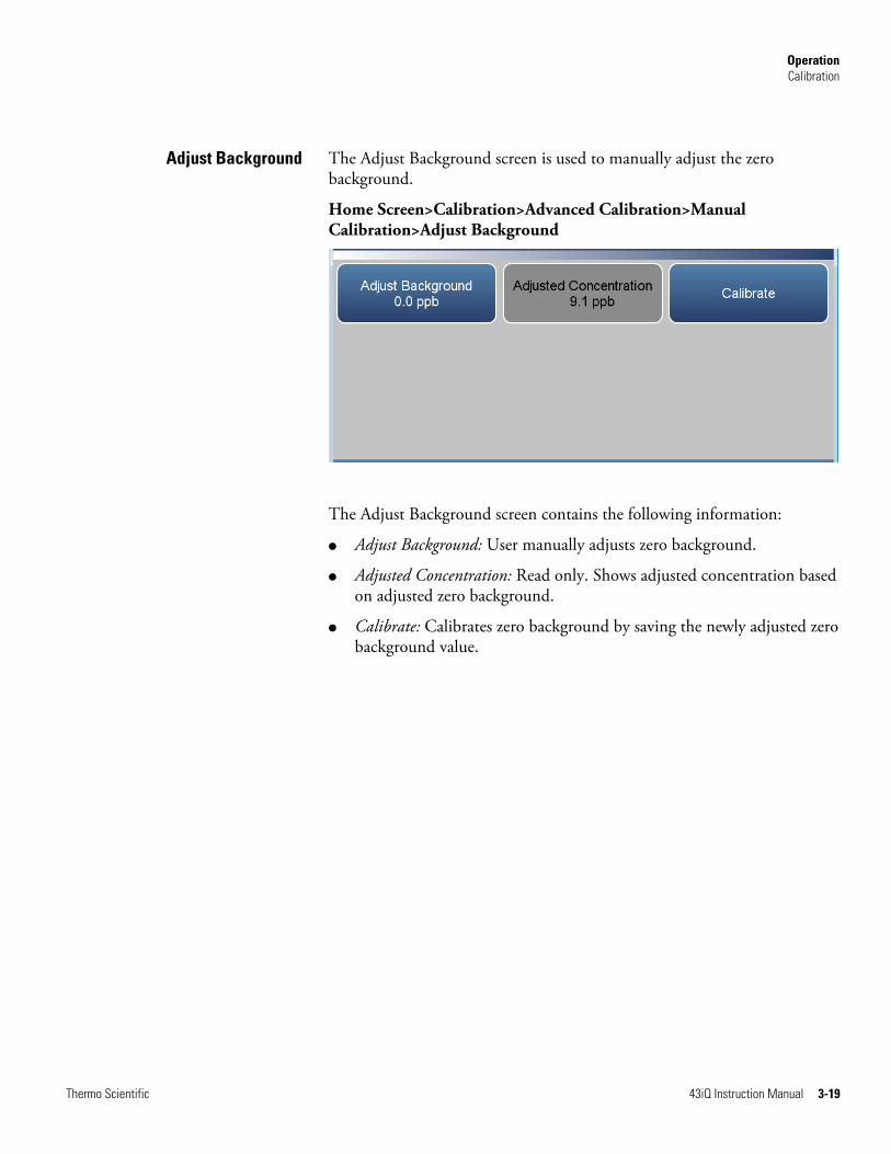
The Adjust Background screen is used to manually adjust the zero background.
Home Screen>Calibration>Advanced Calibration>Manual Calibration>Adjust Background
The Adjust Background screen contains the following information:
● Adjust Background: User manually adjusts zero background.
● Adjusted Concentration: Read only. Shows adjusted concentration based on adjusted zero background.
● Calibrate: Calibrates zero background by saving the newly adjusted zero background value.
Adjust Background

Operation Calibration
3-20 43iQ Instruction Manual Thermo Scientific
The Adjust Span Coefficient screen is used to manually adjust the span coefficient.
The following screen is shown in single range mode and dual or auto range mode. In dual or auto range modes, “High Range” or “Low Range” is displayed to indicate the calibration of the high or low coefficient. The Adjust High Range Span Coefficient and Adjust Low Range Span Coefficient screens function the same way.
Home Screen>Calibration>Advanced>Manual Calibration>Adjust Span Coefficient (single range mode)
Home Screen>Calibration>Advanced Calibration>Manual Calibration>Adjust High Range Span Coefficient (dual or auto range mode)
The Adjust Span Coefficient screen contains the following information:
● Adjust Span Coefficient: User manually adjusts span coefficient when in single range mode.
● Adjusted Concentration: Read only. Shows adjusted concentration based on adjusted span coefficient when in single range mode.
Adjust Span Coefficient

Operation Calibration
Thermo Scientific 43iQ Instruction Manual 3-21
● Adjust High Range Span Coefficient: User manually adjusts high range span coefficient when in dual or auto range mode.
● Adjusted High Range Concentration: Read only. Shows adjusted high range concentration based on adjusted high range span coefficient when in dual or auto range mode.
● Adjust Low Range Span Coefficient: User manually adjusts low range span coefficient when in dual or auto range mode.
● Adjusted High Range Concentration: Read only. Shows adjusted low range concentration based on adjusted low range span coefficient when in dual or auto range mode.
● Calibrate: Calibrates span coefficient by saving the newly adjusted span coefficient.

Operation Calibration
3-22 43iQ Instruction Manual Thermo Scientific
The Calibration History screen shows the log of calibrations and calibration checks performed.
Use the and buttons to move up and down and the and buttons to move left and right.
Home Screen>Calibration>Advanced Calibration>Calibration History
Note Pressing the Calibration History button responds with Retrieving calibration log data, it may take a few seconds... ▲
The Calibration History screen contains the following information:
● Time Stamp: Time of calibration or calibration check.
● Event: Lists the type of calibration event.
● Result: Concentration result.
● Target: Concentration setpoint value.
● Units: Displays units for each item.
● Average Time: Averaging time used during the calibration or calibration check.
Calibration History
Operation Data
Thermo Scientific 43iQ Instruction Manual 3-23
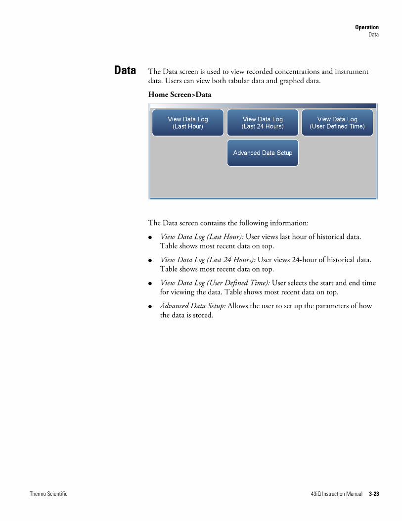
The Data screen is used to view recorded concentrations and instrument data. Users can view both tabular data and graphed data.
Home Screen>Data
The Data screen contains the following information:
● View Data Log (Last Hour): User views last hour of historical data. Table shows most recent data on top.
● View Data Log (Last 24 Hours): User views 24-hour of historical data. Table shows most recent data on top.
● View Data Log (User Defined Time): User selects the start and end time for viewing the data. Table shows most recent data on top.
● Advanced Data Setup: Allows the user to set up the parameters of how the data is stored.
Data

Operation Data
3-24 43iQ Instruction Manual Thermo Scientific
The View Data Log (Last Hour) screen allows the user to view the last hour worth of data in tabular and/or graphical form.
Use the and buttons to move up and down and the and buttons to move left and right.
Home Screen>Data>View Data Log (Last Hour)
Note Pressing the View Data Log (Last Hour) responds with Retrieving user log data, it may take a few seconds... ▲
The View Data Log (Last Hour) screen contains the following options:
● Graph: Displays data graph for the column selected. The graph time axis is defined by the data set in the table.
View Data Log (LastHour)

Operation Data
Thermo Scientific 43iQ Instruction Manual 3-25
The View Data Log (Last 24 Hours) screen allows the user to instantly view the last 24 hours worth of data in real time.
Use the and buttons to move up and down and the and buttons to move left and right.
Home Screen>Data>View Data Log (Last 24 Hours)
Note Pressing the View Data Log (Last 24 Hours) responds with Retrieving user log data, it may take a few seconds... ▲
The View Data Log (Last 24 Hours) screen contains the following options:
● Graph: Displays data graph for the column selected. The graph time axis is defined by the data set in the table.
View Data Log (Last24 Hours)

Operation Data
3-26 43iQ Instruction Manual Thermo Scientific
The View Data (User Defined Time) screen is used to specify the start and end time for viewing the data logging table.
Home Screen>Data>View Data Log (User Defined Time)
Home Screen>Data>View Data Log (User Defined Time)>Save Data Logging Start Time
The View Data Log (User Defined Time) screen contains the following information:
● Date: Sets date of data logging start time.
● Time: Sets time of data logging start time.
● Save Data Logging Start Time: Pressing this button saves the start time and follows directly to the end time selection for the data logging screen.
View Data Log (UserDefined Time)

Operation Data
Thermo Scientific 43iQ Instruction Manual 3-27
The View Data Log (User Defined Time) End Time screen contains the following information:
● Date: Sets date of data logging end time.
● Time: Sets time of data logging end time.
● Save Data Logging End Time: Pressing the Save Data Logging End Time button saves the end time and follows directly to the data logging table.
Note End time should not be greater than 1 year from start time . ▲
Note The datalogging table is limited to 10,000 points. ▲

Operation Data
3-28 43iQ Instruction Manual Thermo Scientific
The Advanced Data Setup screen allows the user to select variables and set up parameters for data logging and streaming data.
Home Screen>Data>Advanced Data Setup
The Advanced Data Setup screen contains the following information:
● Data Logging Setup: User selects the parameters for collecting logged data.
● Streaming Data Setup: User selects the parameters for streaming data to a computer in real time.
Advanced DataSetup

Operation Data
Thermo Scientific 43iQ Instruction Manual 3-29
The Data Logging Setup screen allows the user to select data to be stored and how it is stored.
Home Screen>Data>Advanced>Data Logging Setup
The Data Logging Setup screen contains the following information:
● Select Data Logging Variables: User selects instrument variables to log.
● Period: User selects how often data is collected by setting the duration between logged data values.
● Data Treatment: Toggles between Average, Current, Minimum and Maximum. When set to average, the average value during the period will be recorded. When set to current, the latest data will be recorded. When set to minimum or maximum, the minimum or maximum value during the period will be recorded.
● Erase Data Log Records: Allows the user to erase all values in the data log and updates the data logging table.
Data Logging Setup

Operation Data
3-30 43iQ Instruction Manual Thermo Scientific
The Select Data Logging Variables screen allows the user to select which variables to store. Note: The Data logging and Streaming variable lists are exclusive from each other but contain the same variable selections. The list is based on the instrument’s configuration.
Use the and buttons to scroll through the variables. Select the variables to log by pressing the corresponding cells. Next, press the Commit Changes button to save selections. Yellow buttons indicate that the variable is selected. More than one can be chosen.
Home Screen>Data>Advanced>Data Logging Setup>Select Data Logging Variables
Select Data LoggingVariables

Operation Data
Thermo Scientific 43iQ Instruction Manual 3-31
The Streaming Data Setup screen allows the user to stream data to a computer.
Home Screen>Data>Advanced>Streaming Data Setup
The Streaming Data Setup screen contains the following information:
● Select Streaming Variables: User selects which variables to stream.
● Period: Sets the time between streamed data.
● Show Labels: Toggles on/off. When on, shows variable labels to the left of the variable values.
● Show Timestamp: Toggles on/off. When on, shows timestamp at the beginning of each row of data.
Streaming Data Setup

Operation Data
3-32 43iQ Instruction Manual Thermo Scientific
The Select Streaming Variables screen allows the user to select which variables to track. Note: The Data logging and Streaming variable lists are exclusive from each other but contain the same variable selections. The list is based on the instrument’s configuration.
Use the and buttons to scroll through the variables. Select the variables to log by pressing the corresponding cells. Next, press the Commit Changes button to save selections. Yellow buttons indicate that the variable is selected. More than one can be chosen.
Home Screen>Data>Advanced>Streaming Data Setup>Select Streaming Variables
Select StreamingVariables

Operation Settings
Thermo Scientific 43iQ Instruction Manual 3-33
The Settings screen allows the user to view the status and alarms, set up user preferences, communicate with outside devices and computers, download files to USB, and sets security protocol.
Home Screen>Settings
The Settings screen contains the following information:
● Health Check: View instrument status and alarms, predictive diagnostics, preventive maintenance alerts, maintenance history, email health check report files, and contact Thermo Fisher Scientific technical support.
● Measurement Settings: Allows the user to setup user preferences as related to the concentration readings.
● Communications: Allows the user to communicate with outside devices.
● Instrument Setting: Allows the user to setup alarm setpoints and user preferences.
● Configuration: User selects which options to enable.
● Security Access Levels: User selects security protocol. User can also change security passwords.
● USB Drive: User can update instrument firmware, download data, and change USB password.
● User Contact Information: User sets up their contact information.
● Update Bootloader: Used to update bootloader when an update to the bootloader is available.
Settings

Operation Settings
3-34 43iQ Instruction Manual Thermo Scientific
The Health Check screen is used for viewing instrument status and alarms, predictive diagnostics, preventive maintenance schedules, maintenance history, emailing files describing the health/status of the instrument, and viewing the instrument’s firmware version.
Note This symbol denotes there is an active alarm in the module. ▲
Note This symbol denotes there is an active maintenance alarm or condition in the module. ▲
Home Screen>Settings>Health Check
The Health Check screen contains the following information:
● Status and Alarms: Allows the user to view the status and alarm menus. Menus are broken down according to modules where the user can view instrument readings, setpoints and alarms.
● Predictive Diagnostics: Smart module diagnostics, which shows possible future issues.
● Maintenance History: Allows the user to set up a maintenance schedule and track maintenance history.
● File Sharing and Support: File sharing via email. Support through Thermo Fisher Scientific technical support.
● iQ360: The iQ360 feature is a paid subscription enabling or disabling the instrument to send automated emails to technical support when an alarm or alert is triggered.
● Firmware Version: Shows the instrument’s firmware version.
Health Check

Operation Settings
Thermo Scientific 43iQ Instruction Manual 3-35
The Status and Alarms screen provides information with respect to module alarms. In each screen, instrument readings, setpoints, and low/high alarm values are displayed. If applicable, setpoints and alarms are also settable from the Settings>Instrument Settings screen.
Note This symbol denotes there is an active alarm in the module. ▲
Home Screen>Settings>Health Check>Status and Alarms
The Status and Alarms screen contains the following information:
● Concentration: Displays SO2 concentrations, alarms, and calibration pass/fail status.
● SO2 Bench: Displays bench module alarms and faults.
● Perm Oven: Displays (optional) perm oven module alarms and faults.
● Flow and Pressure: Displays flow and pressure alarms and faults.
● Peripherals Support: Displays peripherals support alarms and faults.
● Analog I/O: Displays analog input/output alarms and faults.
● Digital I/O: Displays digital input/output alarms and faults.
● Valve and Pump Resets: User can reset valve and pump power.
● Serial Numbers: Displays all the serial numbers for the instrument.
Status and Alarms

Operation Settings
3-36 43iQ Instruction Manual Thermo Scientific
The Concentration screen provides status and alarms for SO2 concentration, background cal/checks, and span cal/checks. If the item being monitored goes outside the lower or higher alarm limit, an alarm is activated.
Use the and buttons to move up and down and the and buttons to move left and right.
Home Screen>Settings>Health Check>Status and Alarms>Concentration
The Concentration screen contains the following information:
● Across:
● Concentration: This column lists items associated with the SO2 concentration.
● Value: Displays the current value for each item.
● Low Alarm: Displays low alarm for each item.
● High Alarm: Displays high alarm for each item.
● Span Conc: Span concentration used in the span calibration or span check.
● Units: Displays units for each item.
● Down:
● SO2: SO2 concentration.
● Bkg Check Offset: Displays concentration based on the last attempted background calibration. High alarm shows user defined limit for acceptable background check offset.
Concentration

Operation Settings
Thermo Scientific 43iQ Instruction Manual 3-37
● Span Check Offset: Displays concentration based on the last attempted span calibration. High alarm shows user defined limit for acceptable span check offset (compared to the span concentration value). Span concentration shows span setpoint.
Note If both the low alarm and high alarms are set to zero, then no alarm will show. ▲
Operation Settings
3-38 43iQ Instruction Manual Thermo Scientific
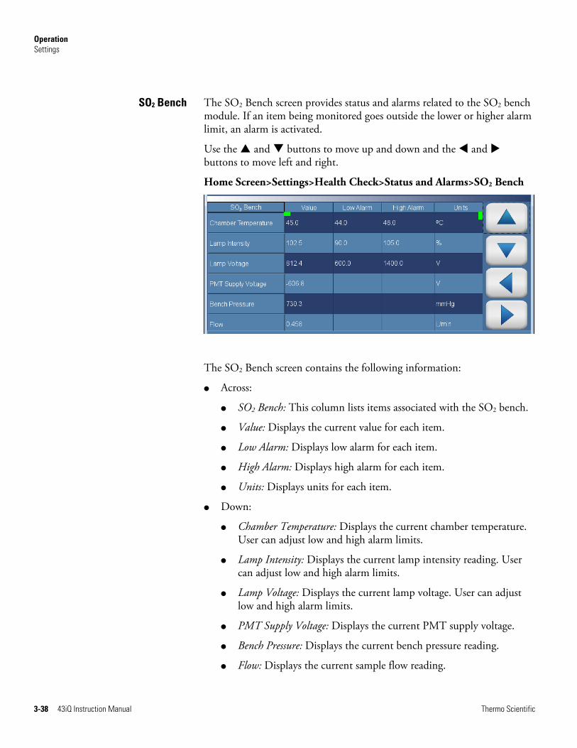
The SO2 Bench screen provides status and alarms related to the SO2 bench module. If an item being monitored goes outside the lower or higher alarm limit, an alarm is activated.
Use the and buttons to move up and down and the and buttons to move left and right.
Home Screen>Settings>Health Check>Status and Alarms>SO2 Bench
The SO2 Bench screen contains the following information:
● Across:
● SO2 Bench: This column lists items associated with the SO2 bench.
● Value: Displays the current value for each item.
● Low Alarm: Displays low alarm for each item.
● High Alarm: Displays high alarm for each item.
● Units: Displays units for each item.
● Down:
● Chamber Temperature: Displays the current chamber temperature. User can adjust low and high alarm limits.
● Lamp Intensity: Displays the current lamp intensity reading. User can adjust low and high alarm limits.
● Lamp Voltage: Displays the current lamp voltage. User can adjust low and high alarm limits.
● PMT Supply Voltage: Displays the current PMT supply voltage.
● Bench Pressure: Displays the current bench pressure reading.
● Flow: Displays the current sample flow reading.
SO2 Bench
Operation Settings
Thermo Scientific 43iQ Instruction Manual 3-39
● Instrument Temp: Displays the current instrument temperature reading.
● Board Communication: Displays OK/Fail for board communication status.
● Power Supply: Displays OK/Fail of power supplies. Power supply goes red if any voltages are outside their limits. No voltage rows ever get highlighted.
● 3.3V Diagnostic: Displays current voltage readings. Alarm limits are not changeable.
● 5V Diagnostic: Displays current voltage readings. Alarm limits are not changeable.
● 15V Diagnostic: Displays current voltage readings. Alarm limits are not changeable.
● 24V Diagnostic: Displays current voltage readings. Alarm limits are not changeable.
Operation Settings
3-40 43iQ Instruction Manual Thermo Scientific
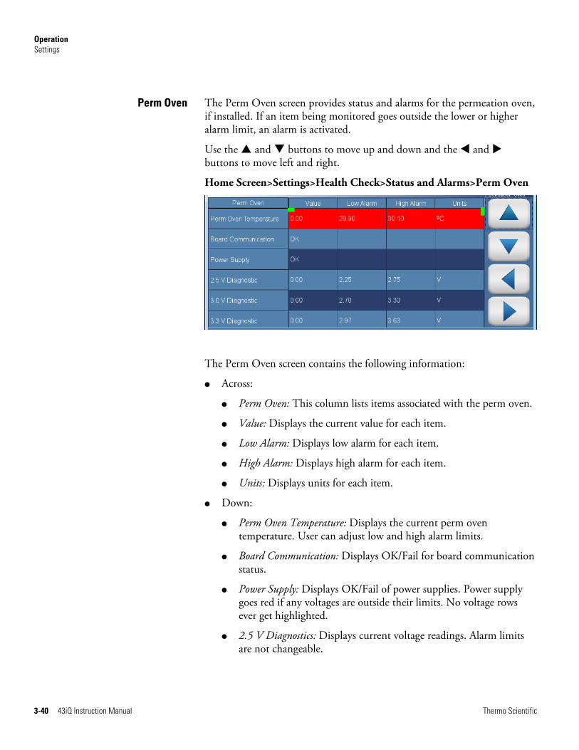
The Perm Oven screen provides status and alarms for the permeation oven, if installed. If an item being monitored goes outside the lower or higher alarm limit, an alarm is activated.
Use the and buttons to move up and down and the and buttons to move left and right.
Home Screen>Settings>Health Check>Status and Alarms>Perm Oven
The Perm Oven screen contains the following information:
● Across:
● Perm Oven: This column lists items associated with the perm oven.
● Value: Displays the current value for each item.
● Low Alarm: Displays low alarm for each item.
● High Alarm: Displays high alarm for each item.
● Units: Displays units for each item.
● Down:
● Perm Oven Temperature: Displays the current perm oven temperature. User can adjust low and high alarm limits.
● Board Communication: Displays OK/Fail for board communication status.
● Power Supply: Displays OK/Fail of power supplies. Power supply goes red if any voltages are outside their limits. No voltage rows ever get highlighted.
● 2.5 V Diagnostics: Displays current voltage readings. Alarm limits are not changeable.
Perm Oven

Operation Settings
Thermo Scientific 43iQ Instruction Manual 3-41
● 3 V Diagnostics: Displays current voltage readings. Alarm limits are not changeable.
● 3.3 V Diagnostics: Displays current voltage readings. Alarm limits are not changeable.
● 5 V Diagnostics: Displays current voltage readings. Alarm limits are not changeable.
● Heater Power Diagnostics: Displays current heater voltage readings. Alarm limits are not changeable.
Operation Settings
3-42 43iQ Instruction Manual Thermo Scientific
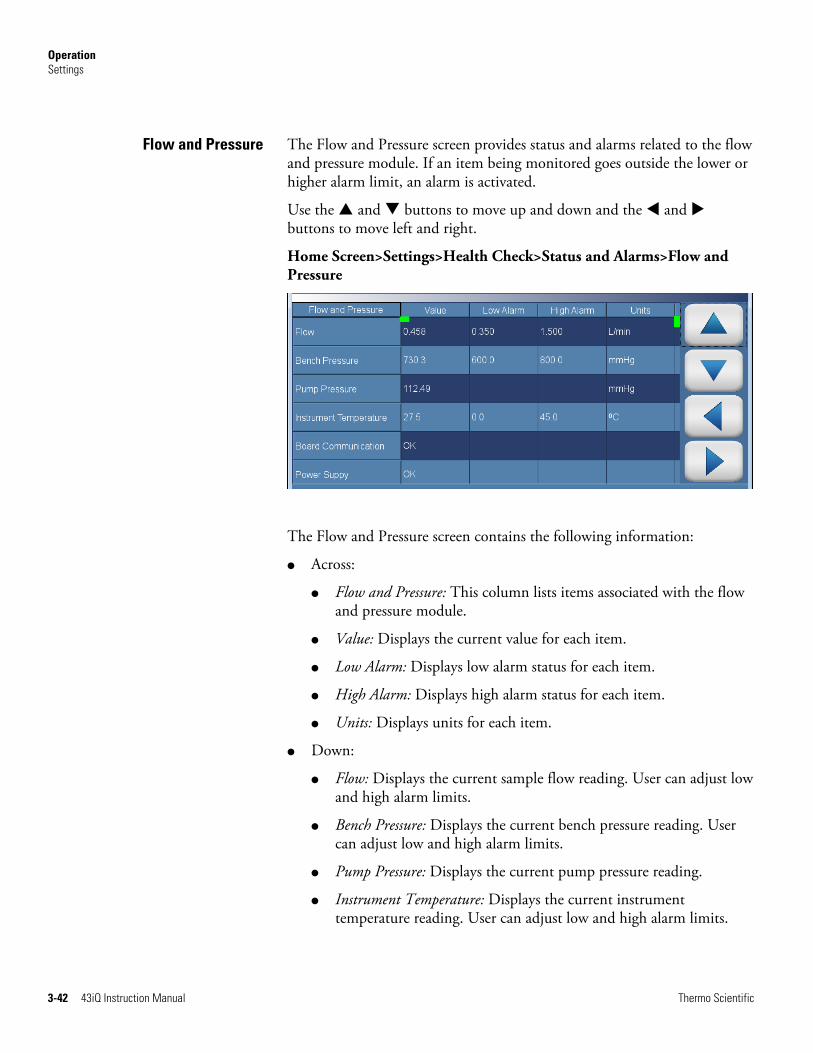
The Flow and Pressure screen provides status and alarms related to the flow and pressure module. If an item being monitored goes outside the lower or higher alarm limit, an alarm is activated.
Use the and buttons to move up and down and the and buttons to move left and right.
Home Screen>Settings>Health Check>Status and Alarms>Flow and Pressure
The Flow and Pressure screen contains the following information:
● Across:
● Flow and Pressure: This column lists items associated with the flow and pressure module.
● Value: Displays the current value for each item.
● Low Alarm: Displays low alarm status for each item.
● High Alarm: Displays high alarm status for each item.
● Units: Displays units for each item.
● Down:
● Flow: Displays the current sample flow reading. User can adjust low and high alarm limits.
● Bench Pressure: Displays the current bench pressure reading. User can adjust low and high alarm limits.
● Pump Pressure: Displays the current pump pressure reading.
● Instrument Temperature: Displays the current instrument temperature reading. User can adjust low and high alarm limits.
Flow and Pressure

Operation Settings
Thermo Scientific 43iQ Instruction Manual 3-43
● Board Communication: Displays OK/Fail for board communication status.
● Power Supply: Displays OK/Fail of power supplies. Power supply goes red if any voltages are outside their limits. No voltage rows ever get highlighted.
● 2.5V Diagnostic: Displays current voltage readings. Alarm limits are not changeable.
● 3.3V Diagnostic: Displays current voltage readings. Alarm limits are not changeable.
● 5.0V Diagnostic: Displays current voltage readings. Alarm limits are not changeable.
● 24V Diagnostic: Displays current voltage readings. Alarm limits are not changeable.
Operation Settings
3-44 43iQ Instruction Manual Thermo Scientific
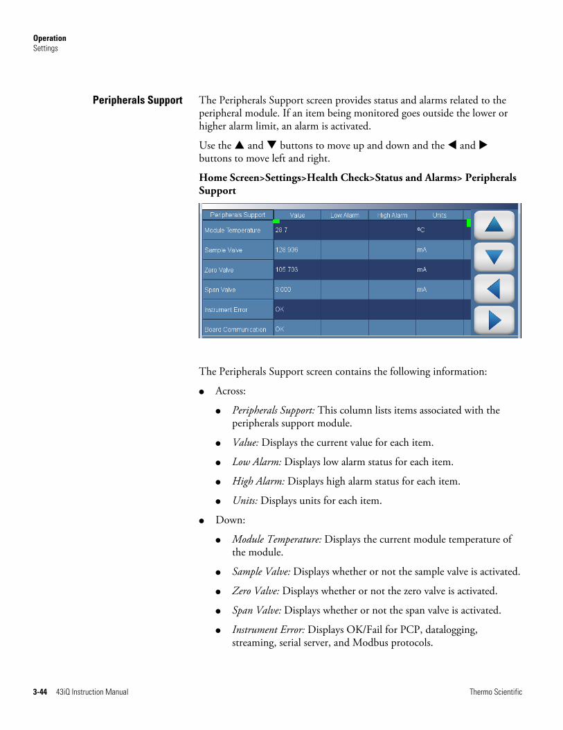
The Peripherals Support screen provides status and alarms related to the peripheral module. If an item being monitored goes outside the lower or higher alarm limit, an alarm is activated.
Use the and buttons to move up and down and the and buttons to move left and right.
Home Screen>Settings>Health Check>Status and Alarms> Peripherals Support
The Peripherals Support screen contains the following information:
● Across:
● Peripherals Support: This column lists items associated with the peripherals support module.
● Value: Displays the current value for each item.
● Low Alarm: Displays low alarm status for each item.
● High Alarm: Displays high alarm status for each item.
● Units: Displays units for each item.
● Down:
● Module Temperature: Displays the current module temperature of the module.
● Sample Valve: Displays whether or not the sample valve is activated.
● Zero Valve: Displays whether or not the zero valve is activated.
● Span Valve: Displays whether or not the span valve is activated.
● Instrument Error: Displays OK/Fail for PCP, datalogging, streaming, serial server, and Modbus protocols.
Peripherals Support

Operation Settings
Thermo Scientific 43iQ Instruction Manual 3-45
● Board Communication: Displays OK/Fail for board communication status.
● Power Supply: Displays OK/Fail of power supplies. Power supply goes red if any voltages are outside their limits. No voltage rows ever get highlighted.
● 2.5V Diagnostic: Displays current voltage readings. Alarm limits are not changeable.
● 3.3V Diagnostic: Displays current voltage readings. Alarm limits are not changeable.
● 5.0V Diagnostic: Displays current voltage readings. Alarm limits are not changeable.
● 24V Diagnostic: Displays current voltage readings. Alarm limits are not changeable.
● 5.0V Step Board 1: Displays current voltage readings. Alarm limits are not changeable.
● 24V Step Board 1: Displays current voltage readings. Alarm limits are not changeable.
● 5.0V Step Board 2: Displays current voltage readings. Alarm limits are not changeable.
● 24V Step Board 2: Displays current voltage readings. Alarm limits are not changeable.

Operation Settings
3-46 43iQ Instruction Manual Thermo Scientific
The Valve and Pump Resets screen allows the user to reset a valve or pump after a failure due to excessive amperage.
Note This symbol denotes that the device needs to be reset. ▲
Note Resetting one valve will reset all valves. ▲
Home Screen>Settings>Health Check>Status and Alarms>Valve and Pump Resets
The Valve and Pump Resets screen contains the following information:
● Sample Valve Reset: Resets sample valve.
● Zero Valve Reset: Resets zero valve.
● Span Valve Reset: Resets span valve.
● Pump Reset: Resets pump.
Valve and Pump Resets
Operation Settings
Thermo Scientific 43iQ Instruction Manual 3-47
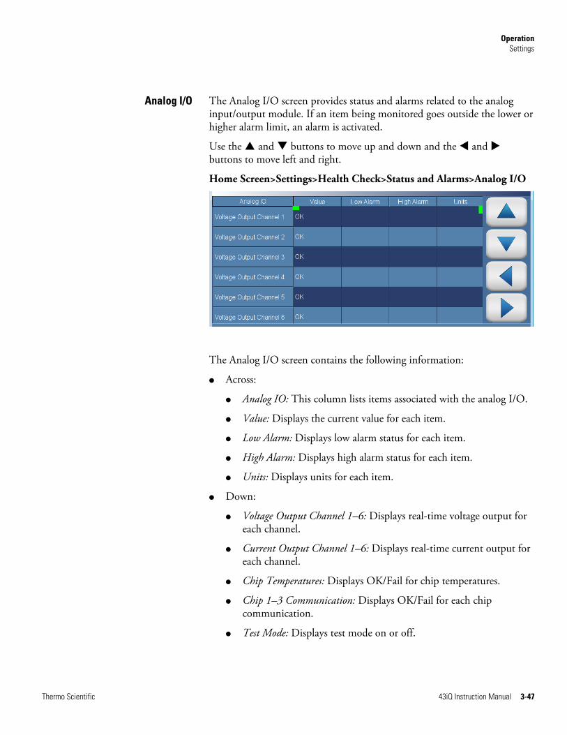
The Analog I/O screen provides status and alarms related to the analog input/output module. If an item being monitored goes outside the lower or higher alarm limit, an alarm is activated.
Use the and buttons to move up and down and the and buttons to move left and right.
Home Screen>Settings>Health Check>Status and Alarms>Analog I/O
The Analog I/O screen contains the following information:
● Across:
● Analog IO: This column lists items associated with the analog I/O.
● Value: Displays the current value for each item.
● Low Alarm: Displays low alarm status for each item.
● High Alarm: Displays high alarm status for each item.
● Units: Displays units for each item.
● Down:
● Voltage Output Channel 1–6: Displays real-time voltage output for each channel.
● Current Output Channel 1–6: Displays real-time current output for each channel.
● Chip Temperatures: Displays OK/Fail for chip temperatures.
● Chip 1–3 Communication: Displays OK/Fail for each chip communication.
● Test Mode: Displays test mode on or off.
Analog I/O

Operation Settings
3-48 43iQ Instruction Manual Thermo Scientific
● Board Communication: Displays OK/Fail for board communication status.
● Power Supply: Displays OK/Fail of power supplies. Power supply goes red if any voltages are outside their limits. No voltage rows ever get highlighted.
● 3.3V Diagnostic: Displays current voltage readings. Alarm limits are not changeable.
● 5.0V Diagnostic: Displays current voltage readings. Alarm limits are not changeable.
● 5.0V Ref Diagnostic: Displays current voltage readings. Alarm limits are not changeable.
● 15V Diagnostic: Displays current voltage readings. Alarm limits are not changeable.
● -15V Diagnostic: Displays current voltage readings. Alarm limits are not changeable.

Operation Settings
Thermo Scientific 43iQ Instruction Manual 3-49
The Digital I/O screen provides status and alarms related to the digital input/output module. If an item being monitored goes outside the lower or higher alarm limit, an alarm is activated.
Use the and buttons to move up and down and the and buttons to move left and right.
Home Screen>Settings>Health Check>Status and Alarms>Digital I/O
The Digital I/O screen contains the following information:
● Across:
● Digital IO: This column lists items associated with the digital I/O.
● Value: Displays the current value for each item.
● Reset: Resets item.
● Low Alarm: Displays low alarm status for each item.
● High Alarm: Displays high alarm status for each item.
● Units: Displays units for each item.
● Down:
● Solenoid 1–8: Displays whether or not the solenoid is activated by showing the current in mA.
● External Alarm 1–3: Displays OK/Fail for external alarms.
● Relay Test Mode: Displays relay test mode on or off.
● Solenoid Test Mode: Displays solenoid test mode on or off.
● Board Communication: Displays OK/Fail for communication status.
Digital I/O
Operation Settings
3-50 43iQ Instruction Manual Thermo Scientific
● Power Supply: Displays OK/Fail of power supplies. Power supply goes red if any voltages are outside their limits. No voltage rows ever get highlighted.
● 3.3V Diagnostic: Displays current voltage readings. Alarm limits are not changeable.
● 5.0V Diagnostic: Displays current voltage readings. Alarm limits are not changeable.
● 24V Diagnostic: Displays current voltage readings. Alarm limits are not changeable.

Operation Settings
Thermo Scientific 43iQ Instruction Manual 3-51
The Serial Numbers screen displays the serial number for each module.
Home Screen>Settings>Health Check>Status and Alarms>Serial Numbers
The Serial Numbers screen contains the following information:
● Instrument: Instrument serial number.
● SO2 Bench: SO2 bench serial number.
● Perm Oven: Optional perm oven serial number.
● Flow and Pressure: Flow and pressure serial number.
● Peripherals Support: Peripherals support serial number.
● Analog I/O: Analog I/O serial number.
● Digital I/O: Digital I/O serial number.
Serial Numbers
Operation Settings
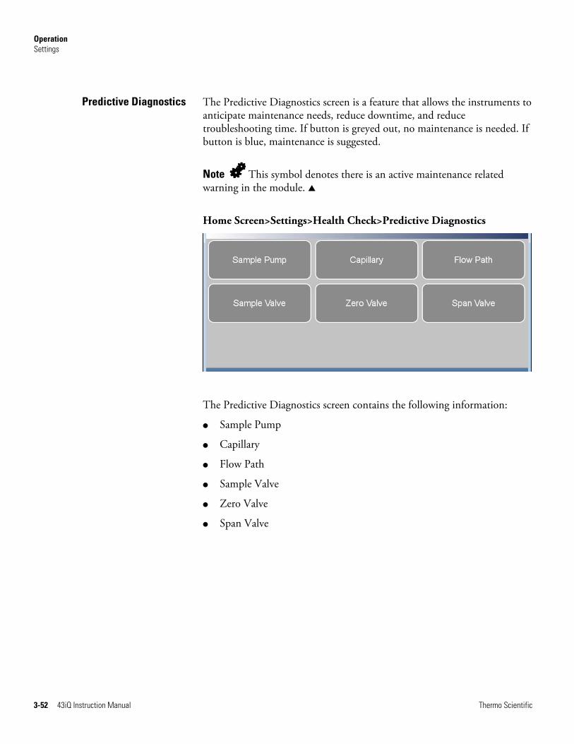
3-52 43iQ Instruction Manual Thermo Scientific
The Predictive Diagnostics screen is a feature that allows the instruments to anticipate maintenance needs, reduce downtime, and reduce troubleshooting time. If button is greyed out, no maintenance is needed. If button is blue, maintenance is suggested.
Note This symbol denotes there is an active maintenance related warning in the module. ▲
Home Screen>Settings>Health Check>Predictive Diagnostics
The Predictive Diagnostics screen contains the following information:
● Sample Pump
● Capillary
● Flow Path
● Sample Valve
● Zero Valve
● Span Valve
Predictive Diagnostics

Operation Settings
Thermo Scientific 43iQ Instruction Manual 3-53
The Maintenance screen reminds the user when certain instrument components need to be serviced/replaced.
Note This symbol denotes there is an active maintenance related warning in the module. ▲
Home Screen>Settings>Health Check>Maintenance
Home Screen>Settings>Health Check>Maintenance>Advanced Maintenance
The Maintenance screen contains the following information:
● Preventive Maintenance: Shows suggested service interval and time left for component replacement.
● Change Part: User logs component fix.
● Maintenance History: Shows the log of all recorded component fixes.
● Service Tips: Provides video and procedural service tips.
● Advanced Maintenance: Resets all preventive maintenance items.
Maintenance
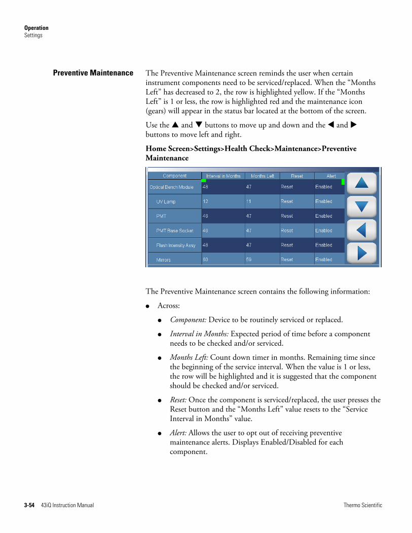
Operation Settings
3-54 43iQ Instruction Manual Thermo Scientific
The Preventive Maintenance screen reminds the user when certain instrument components need to be serviced/replaced. When the “Months Left” has decreased to 2, the row is highlighted yellow. If the “Months Left” is 1 or less, the row is highlighted red and the maintenance icon (gears) will appear in the status bar located at the bottom of the screen.
Use the and buttons to move up and down and the and buttons to move left and right.
Home Screen>Settings>Health Check>Maintenance>Preventive Maintenance
The Preventive Maintenance screen contains the following information:
● Across:
● Component: Device to be routinely serviced or replaced.
● Interval in Months: Expected period of time before a component needs to be checked and/or serviced.
● Months Left: Count down timer in months. Remaining time since the beginning of the service interval. When the value is 1 or less, the row will be highlighted and it is suggested that the component should be checked and/or serviced.
● Reset: Once the component is serviced/replaced, the user presses the Reset button and the “Months Left” value resets to the “Service Interval in Months” value.
● Alert: Allows the user to opt out of receiving preventive maintenance alerts. Displays Enabled/Disabled for each component.
Preventive Maintenance
Operation Settings
Thermo Scientific 43iQ Instruction Manual 3-55
● Down:
● Optical Bench Module: Service interval for optical bench module components.
● UV Lamp: Service interval for UV lamp.
● PMT: Service interval for PMT.
● PMT Base Socket: Service interval for PMT base socket.
● Flash Intensity Assembly: Service interval for flash intensity assembly.
● Mirrors: Service interval for mirrors.
● Permeation Tube: Service interval for permeation tube.
● Flow System: Service interval for the flow system components.
● Capillaries: Service interval for capillaries.
● Pump: Service interval for pump.
● DC Power Supply: Service interval for DC power supply.
● Fan Filter: Service interval for fan filter.
● System Components: Service interval for system components.
● Purafil: Service interval for purafil.
● Charcoal: Service interval for charcoal.
● Dri-Rite: Service interval for dri-rite.

Operation Settings
3-56 43iQ Instruction Manual Thermo Scientific
The Change Part screen allows the user to enter the component being serviced and the type of fix. Pressing commit will update the preventive maintenance table and predictive diagnostics screen when applicable.
Home Screen>Settings>Health Check>Maintenance>Change Part
The Change Part screen contains the following information:
● Select Part: User selects part to service from the selection table.
● Fix: User chooses from new, rebuilt, cleaned, and unknown.
● Comment: User can write a brief comment, which will be saved to the preventive maintenance history table.
● Commit: User commits and saves the selected part fix.
Change Part

Operation Settings
Thermo Scientific 43iQ Instruction Manual 3-57
The Maintenance History screen allows the user to view when components are replaced, rebuilt, or cleaned. When a user changes a part in the change part screen, the new row will be automatically created at the top in the maintenance history table.
Use the and buttons to move up and down and the and buttons to move left and right.
Home Screen>Settings>Health Check>Maintenance>Maintenance History
Note Retrieving maintenance history data, it may take a few seconds... ▲
The Maintenance History screen contains the following information:
● Part: Component that has been fixed.
● Fix: The type of maintenance.
● Date: Shows date/time when service was logged.
● Service Months: Amount of time in months since last service.
● Comments: Shows comments entered from time of change.
Maintenance History

Operation Settings
3-58 43iQ Instruction Manual Thermo Scientific
The File Sharing and Support screen allows the user to send health check report files to Thermo Fisher Scientific technical support or user emails. The Health Report file includes: Status and Alarms, PM Alerts, Activity Log, Service Database, Cal History, and Data Log (last 24 hours).
Note To create email list, go to Settings>User Contact Information. To configure email, go to Settings>Communications>Email Server (SMTP). ▲
Home Screen>Settings>Health Check>File Sharing and Support
The File Sharing and Support screen contains the following information:
● Download Health Check Report to USB Drive: Sends the health report to USB drive.
● Email Health Check Report File to Technical Support: Sends the health report file to technical support and the customer email addresses via email.
● Email Health Check Report to Personal Account: Sends the health report file to a personal account via email.
● iQ Alert Assistant: With the iQ Alert Assistant enabled, the instrument will email Thermo Scientific Technical Support the health check report after each event. After each maintenance alert or predictive diagnostic alert, Customer Service will produce a quote for the components that require service. This quote will get emailed to the email addresses that have been entered into the “User Contact Information” menu.
● 3rd Party Services: The 3rd party services feature is a paid subscription, which allows a service provider to enable or disable automated email notifications when an alarm or alert is triggered.
File Sharing and Support

Operation Settings
Thermo Scientific 43iQ Instruction Manual 3-59
The iQ360 is a paid subscription enabling or disabling the instrument to send automated emails to technical support when an alarm or alert is triggered.
Home Screen>Settings>Health Check>iQ360 (Get Started)
Home Screen>Settings>Health Check>iQ360 (Status and Renewal Request)
The iQ360 screen contains the following information:
● Get Started: Allows the user to access the menu where the subscription passcode is entered.
● Status and Renewal Request: Allows the user to access the iQ360 menu once the subscription has been enabled.
● Cancel and Return to the Home Screen: Exits screen and returns to the Home Screen.
iQ360

Operation Settings
3-60 43iQ Instruction Manual Thermo Scientific
The Get Started screen allows the user to access the menu where the subscription passcode is entered.
Home Screen>Settings>Health Check>iQ360>Get Started
The Get Started screen contains the following information:
● Resend Subscription E-mail: Allows the user to request another subscription passcode if the email was never received.
● Enter Subscription Access Code: Allows the user to enter the subscription passcode to enable an iQ360 subscription.
● Exit and Return to the Home Screen: Exits screen and returns to the Home Screen.
Get Started

Operation Settings
Thermo Scientific 43iQ Instruction Manual 3-61
The Status and Renewal Request screen allows the user to access the iQ360 menu once the subscription has been enabled.
Home Screen>Settings>Health Check>iQ360>Status and Renewal Request
The Status and Renewal Request screen contains the following information:
● iQ360 Status: Informs the user if the subscription is enabled.
● iQ360 Subscription Expiration Date: Informs the user when the subscription will expire.
● iQ360 Test Connection: Allows the user to verify the network connection is working.
● iQ360 Subscription Renewal: Allows the user to request a subscription renewal via email.
Status and Renewal Request
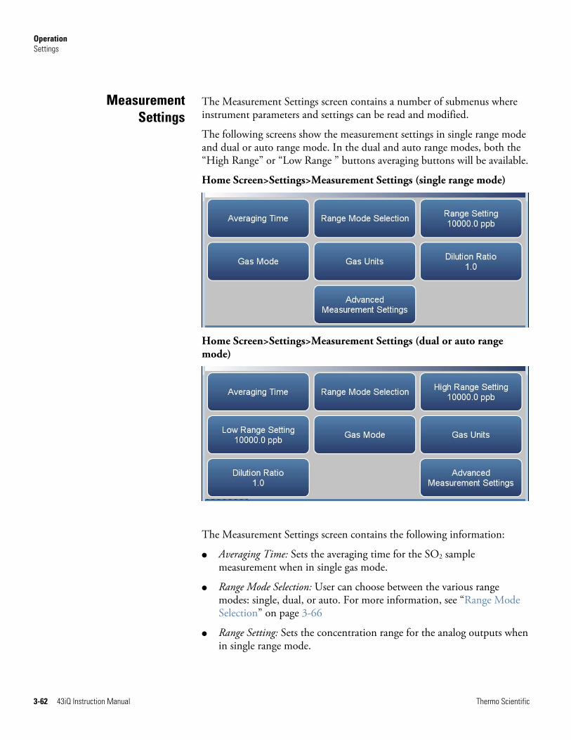
Operation Settings
3-62 43iQ Instruction Manual Thermo Scientific
The Measurement Settings screen contains a number of submenus where instrument parameters and settings can be read and modified.
The following screens show the measurement settings in single range mode and dual or auto range mode. In the dual and auto range modes, both the “High Range” or “Low Range ” buttons averaging buttons will be available.
Home Screen>Settings>Measurement Settings (single range mode)
Home Screen>Settings>Measurement Settings (dual or auto range mode)
The Measurement Settings screen contains the following information:
● Averaging Time: Sets the averaging time for the SO2 sample measurement when in single gas mode.
● Range Mode Selection: User can choose between the various range modes: single, dual, or auto. For more information, see “Range Mode Selection” on page 3-66
● Range Setting: Sets the concentration range for the analog outputs when in single range mode.
MeasurementSettings
Operation Settings
Thermo Scientific 43iQ Instruction Manual 3-63
● High Range Setting: Sets the high range concentration range for the analog output when in dual or auto range mode.
● Low Range Setting: Sets the low range concentration for the analog output when in dual or auto range mode.
● Gas Mode: User can manually choose sample, zero or span mode.
● Gas Units: Defines the units in which SO2 concentration reading is expressed.
● Dilution Ratio: Serves as a multiplier when dilution gas is utilized.
● Advanced Measurement Settings: Advanced settings affecting SO2 readings.

Operation Settings
3-64 43iQ Instruction Manual Thermo Scientific
The Averaging Time screen allows the user to choose dynamic filtering or a manually selected (static) averaging time.
Averaging Time defines the time period (1 to 300 seconds) during which SO2 measurements are taken. The average concentration of the readings are calculated for that time period. The front panel display and analog outputs are updated every second if averaging time is greater than 1 second. An averaging time of 10 seconds, for example, means that the average concentration of the last 10 seconds will be displayed at each update. An averaging time of 300 seconds means that the moving average concentration of the last 300 seconds will be the output at each update (every 10 seconds). Therefore, the lower the averaging time the faster the front panel display and analog outputs respond to concentration changes. Longer averaging times are typically used to smooth output data.
Dynamic Filtering allows for data smoothing without compromising response time. The instrument automatically changes the averaging time giving the user faster response times when conditions are rapidly changing; smoother and stable readings, when conditions aren’t changing as rapidly; and as an added bonus, it better processes spikes to minimize their impact on the data. At the same time it will preserve the representative nature of the filtered data to the conditions being sampled.
Note When Dynamic Filtering is selected, the user selected Averaging Time button is disabled. ▲
Home Screen>Settings>Measurement Settings>Averaging Time (single range mode)
Averaging Time
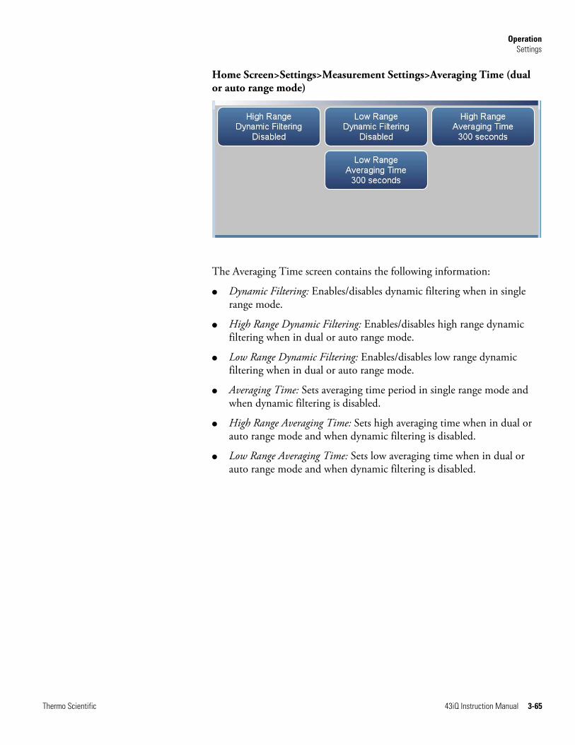
Operation Settings
Thermo Scientific 43iQ Instruction Manual 3-65
Home Screen>Settings>Measurement Settings>Averaging Time (dual or auto range mode)
The Averaging Time screen contains the following information:
● Dynamic Filtering: Enables/disables dynamic filtering when in single range mode.
● High Range Dynamic Filtering: Enables/disables high range dynamic filtering when in dual or auto range mode.
● Low Range Dynamic Filtering: Enables/disables low range dynamic filtering when in dual or auto range mode.
● Averaging Time: Sets averaging time period in single range mode and when dynamic filtering is disabled.
● High Range Averaging Time: Sets high averaging time when in dual or auto range mode and when dynamic filtering is disabled.
● Low Range Averaging Time: Sets low averaging time when in dual or auto range mode and when dynamic filtering is disabled.

Operation Settings
3-66 43iQ Instruction Manual Thermo Scientific
The Range Mode Selection screen is used to switch between the various range modes: Single, Dual, and Auto Range.
Home Screen>Settings>Measurement Settings>Range Mode Selection
The Range Mode Selection screen contains the following information:
● Single: In single range mode, there is one range, one averaging time, and one span coefficient.
● Dual: In the dual range mode, there are two independent analog outputs. These are labeled simply as the “High Range” and the “Low Range”. Each channel has its own analog output range setting, averaging time, and span coefficient.
This enables the sample concentration reading to be sent to the analog outputs at two different ranges. For example, the low SO2 analog output can be set to output concentrations from 0 to 50 ppb and the high SO2 analog output set to output concentrations from 0 to 100 ppb.
In addition, each SO2 analog output has a span coefficient so that each range can be calibrated separately. This is especially necessary if the two ranges are not close to one another. For example, the low SO2 range is set to 0–50 ppb and the high SO2 range is set to 0–10000 ppb.
● Auto: The auto range mode switches the SO2 analog outputs between high and low range settings, depending on the concentration level. The high and low ranges are defined in the Range Settings screen.
For example, suppose the low range is set to 50 ppb and the high range is set to 100 ppb, as shown below. Sample concentrations below 50 ppb are output based on low range selection and sample concentrations above 50 ppb are output based on high range selection. When the low range is active, the range mode selection status output is at 0 volts.
Range Mode Selection

Operation Settings
Thermo Scientific 43iQ Instruction Manual 3-67
When the high range is active, the range mode selection status output is at half of full-scale.
When the high range is active, the concentration must drop to 95% of the low SO2 range for the low range to become active.
In addition, each SO2 range and analog output has a span coefficient so that each range can be calibrated separately. This is especially necessary if the two ranges are not close to one another. For example, the low SO2 range is set to 0–50 ppb and the high SO2 range is set to 0–10000 ppb.

Operation Settings
3-68 43iQ Instruction Manual Thermo Scientific
The Range Setting screen defines the concentration range of the analog outputs. For example, an SO2 range of 0–50 ppb restricts the analog output to concentrations between 0 and 50 ppb.
The screen shows the current SO2 range. The range screen is similar for the single, dual, and auto range modes. The only difference between the screens are the words “High” or “Low” displayed to indicate which range is displayed. For more information about the dual and auto range modes, see “Range Mode Selection” on page 3-66. Pressing Range Setting, High Range Setting or Low Range Setting, brings up a numeric keypad whereby the user can select a range.
Settable standard ranges according to unit selection include:
ppb 5010000 ppb
ppm 0.0510 ppm
% 5e-060.001 %
μg/m3 20025000 μg/m3
mg/m3 0.225 mg/m3
g/m3 0.00020.01 g/m3
Settable extended ranges according to unit selection include:
ppb 50100000 ppb
ppm 0.05100 ppm
% 5e-060.01 %
μg/m3 200250000 μg/m3
mg/m3 0.2250 mg/m3
g/m3 0.00020.25 g/m3
Range Setting

Operation Settings
Thermo Scientific 43iQ Instruction Manual 3-69
The Gas Mode screen defines what gas mode the instrument is set to.
Home Screen>Settings>Measurement Settings>Gas Mode
The Gas Mode screen contains the following information:
● Sample: Sets the instrument to measure sample gas.
● Zero: Used when calibrating the background of the instrument. When pressed, sets the instrument to zero mode.
● Span: Used when calibrating the span coefficient. When pressed, sets the instrument to span mode.
● External Span: If optional perm oven is installed, allows the use of an external span source in addition to the internal permeation span.
Gas Mode

Operation Settings
3-70 43iQ Instruction Manual Thermo Scientific
The Gas Units screen defines how the SO2 concentration reading is expressed. The μg/m3, mg/m3, and g/m3 gas concentration modes are calculated using a standard pressure of 760 mmHg and a standard temperature of 0 °C. The temperature can be changed in the compensation screen.
Use the and buttons to select.
Home Screen>Settings>Measurement Settings>Gas Units
The Gas Units screen contains the following information:
● ppb: parts per billion.
● ppm: parts per million.
● %: percent.
● μg/m3: micrograms per meter cubed.
● mg/m3: milligrams per meter cubed.
● g/m3: grams per meter cubed.
Gas Units
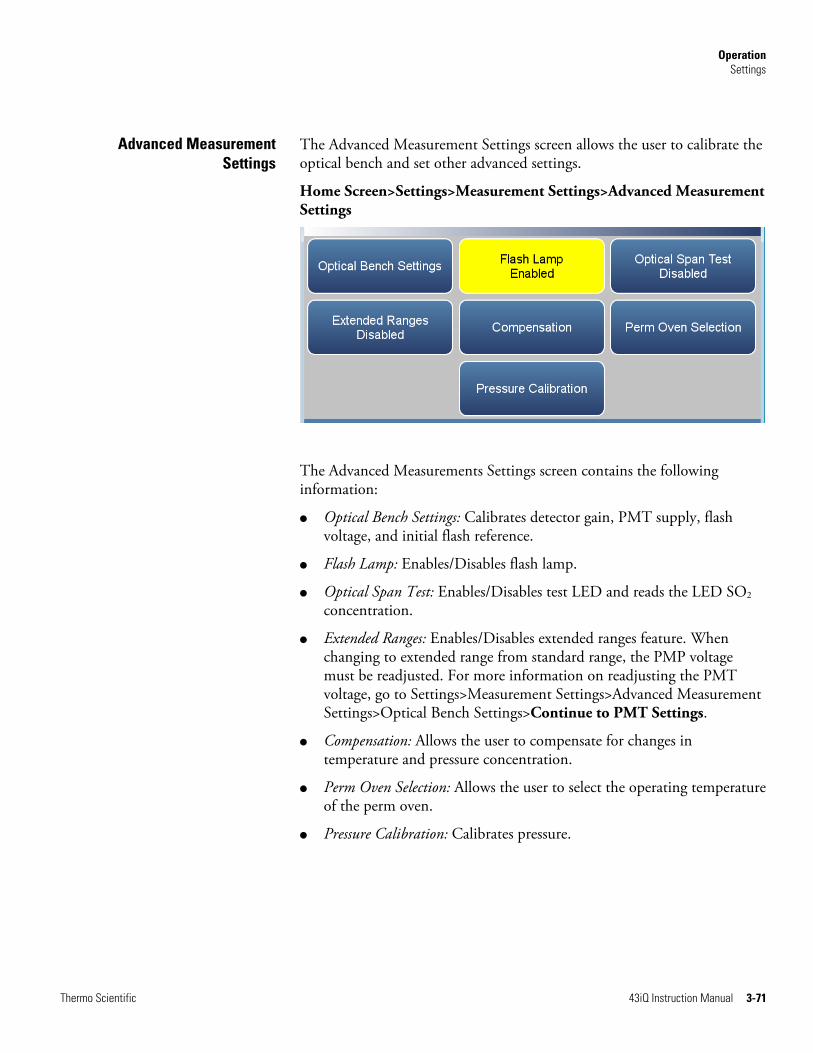
Operation Settings
Thermo Scientific 43iQ Instruction Manual 3-71
The Advanced Measurement Settings screen allows the user to calibrate the optical bench and set other advanced settings.
Home Screen>Settings>Measurement Settings>Advanced Measurement Settings
The Advanced Measurements Settings screen contains the following information:
● Optical Bench Settings: Calibrates detector gain, PMT supply, flash voltage, and initial flash reference.
● Flash Lamp: Enables/Disables flash lamp.
● Optical Span Test: Enables/Disables test LED and reads the LED SO2 concentration.
● Extended Ranges: Enables/Disables extended ranges feature. When changing to extended range from standard range, the PMP voltage must be readjusted. For more information on readjusting the PMT voltage, go to Settings>Measurement Settings>Advanced Measurement Settings>Optical Bench Settings>Continue to PMT Settings.
● Compensation: Allows the user to compensate for changes in temperature and pressure concentration.
● Perm Oven Selection: Allows the user to select the operating temperature of the perm oven.
● Pressure Calibration: Calibrates pressure.
Advanced MeasurementSettings

Operation Settings
3-72 43iQ Instruction Manual Thermo Scientific
The Optical Bench Settings screen allows the user to calibrate the optical bench. The calibration in this screen should be performed if the part associated with the optical bench has been changed/repaired or if the span coefficient is outside the limit of 0.5 to 2.0.
Use the and buttons to move up and down and the and buttons to move left and right.
Home Screen>Settings>Measurement Settings>Advanced Measurement Settings>Optical Bench Settings
Home Screen>Settings>Measurement Settings>Advanced Measurement Settings>Optical Bench Settings>Continue To Detector Gain Settings Screen
The Detector Gain Settings screen contains the following information:
● Across:
● Description: Define the actions the user can do.
● Detector Gain: User can manually set or automatically calibrate the detector gain.
Optical Bench Settings

Operation Settings
Thermo Scientific 43iQ Instruction Manual 3-73
● Lamp Voltage: Displays the current lamp voltage.
● Lamp Intensity: Displays the current lamp intensity.
● Down:
● Manual Entry: Shows current value. If pressed, user can manually set the detector gain value.
● Auto Cal: When pressed, the detector’s auto-calibration process is initiated. Please allow up to 5 minutes for calibration to complete. User can stop calibration by pressing the Stop button under Detector Gain.
● End Cal: When pressed, the auto calibration is interrupted and the value does not change.
● Default Values: When pressed, the default gain for the lamp intensity detector is restored.
Home Screen>Settings>Measurement Settings>Advanced Measurement Settings>Optical Bench Settings>Continue To PMT Settings Screen
The PMT Settings screen contains the following information:
● Across:
● Description: Defines the actions the user can do.
● PMT Supply: User can manually adjust the PMT supply value, read target and calibration concentration, start/stop automatic calibration, read voltage, frequency and zero offset frequency values, and reset default values.
● Current PMT: Displays the current PMT voltage value.
● Units: Displays units for each item.

Operation Settings
3-74 43iQ Instruction Manual Thermo Scientific
● Down:
● Manual Entry: Shows current value. If the PMT supply cell is pressed, user can manually change the value.
● Target Concentration: Displays target concentration.
● Calibration Concentration: Displays calibration concentration.
● Auto Calibration: When pressed, the auto-calibration process is initiated. Please allow up to 5 minutes for calibration to complete.
● End Calibration: When pressed, the auto calibration is interrupted and the value does not change.
● Default Values: When pressed, the default PMT voltage setting is restored.

Operation Settings
Thermo Scientific 43iQ Instruction Manual 3-75
The Compensation screen provides compensation for any changes to the instrument’s output signal due to internal instrument temperature, and pressure variations.
Home Screen>Settings>Measurement Settings>Advanced Measurement Settings>Compensation
The Compensation screen contains the following information:
● Temp Compensation: Toggles temperature compensation enabled or disabled and provides compensation for any changes to the instrument's output signal due to internal instrument temperature variations. The effects of internal instrument temperature changes on the analyzer's subsystems and output have been empirically determined. This empirical data is used to compensate for any changes in temperature.
● Pressure Compensation: Toggles pressure compensation enabled or disabled and provides compensation for any changes to the instrument's output signal due to bench pressure variations. The effects of bench pressure changes on the analyzer's subsystems and output have been empirically determined. This empirical data is used to compensate for any change in bench pressure.
● Standard Temperature for Gas Units: Allows the user to enter a value between 0 and 30 °C to correct the g/m3, mg/m3, and g/m3 concentration calculations.
Compensation

Operation Settings
3-76 43iQ Instruction Manual Thermo Scientific
The Pressure Calibration screen is used to calibrate the pressure sensor to zero, span, or factory default values.
Use the and buttons to move up and down and the and buttons to move left and right.
Home Screen>Settings>Measurement Settings>Advanced Measurement Settings>Pressure Calibration
The Pressure Calibration screen contains the following information:
● Across:
● Description: Lists items in table.
● Reading: Displays reading of each pressure sensor.
● Calibration: Starts calibration or resets default values.
● Down:
● Sensor 13 Reading: Under the column labeled Reading, current reading of each pressure sensor.
● Atmospheric Sensor 13: Under the column labeled reading, the user enters the current atmospheric pressure in mmHg units. Under the column labelled Calibration, the user presses the Start button to calibrate the high point of the sensor.
● Zero Sensor 13: User should put the pressure sensor under a strong vacuum. Under the column labeled reading, the user enters the pressure in mmHg. Under the column labeled Calibration, the user presses the Start button to calibrate the low point of the sensor.
● Reset all values: Resets values to default.
Pressure Calibration

Operation Settings
Thermo Scientific 43iQ Instruction Manual 3-77
The Communications screen allows the user to set TCP/DHCP parameters, Serial settings, Analog I/O and Digital I/O, Email Server, and Instrument ID. Buttons are grayed out if not selected in Settings>Configuration.
Home Screen>Settings>Communications
The Communications screen contains the following information:
● Wired TCP/DHCP: Settings for communicating with the instrument through wired Ethernet.
● Serial RS-232/485: Settings for communicating with the instrument through RS-232/485 protocol. This is only visible if selected in Settings>Configuration>Communications Board.
● Analog I/O: Settings for communicating with the instrument through analog I/O settings. This is only visible if selected in Settings>Configuration>Analog I/O.
● Digital I/O: Settings for communicating with the instrument through digital I/O settings. This is only visible if selected in Settings>Configuration>Digital I/O.
● Email Server (SMTP): Settings for communication with email.
● Instrument ID: Allows the user to edit the instrument identification number (ID). The ID is used to identify the instrument when using protocols to control the instrument or collect data. It may be necessary to edit the ID number if two or more of instruments of the same model are connected to one computer. Valid instrument ID numbers are from 0 to 127. The 43iQ has a default instrument ID of 1.
● Bayern Hessen Settings: User selects the registers (measured values) that the instrument should respond with, in response to a valid data query (DA) command.
Communications

Operation Settings
3-78 43iQ Instruction Manual Thermo Scientific
Note Refer to the “Bayern Hessen Protocol” section in the Communications Manual for a detailed description. ▲
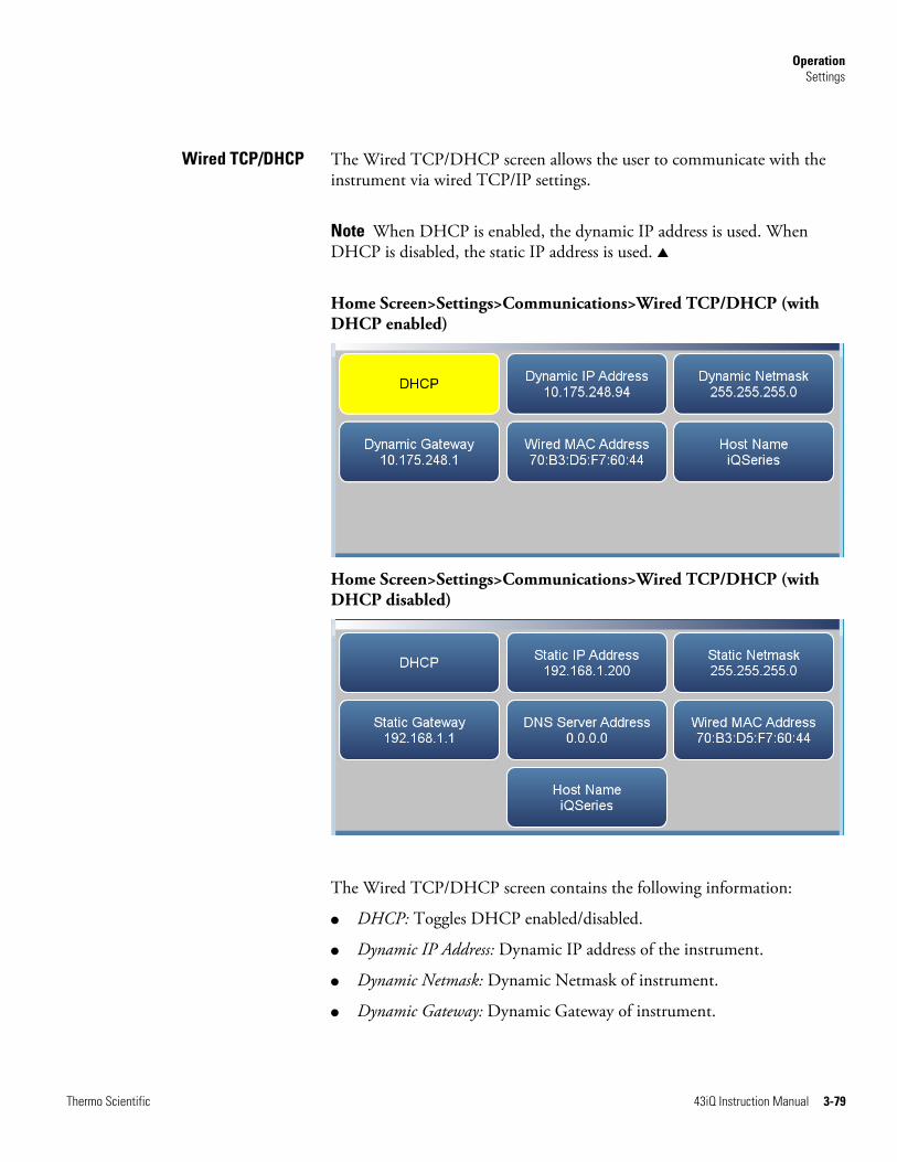
Operation Settings
Thermo Scientific 43iQ Instruction Manual 3-79
The Wired TCP/DHCP screen allows the user to communicate with the instrument via wired TCP/IP settings.
Note When DHCP is enabled, the dynamic IP address is used. When DHCP is disabled, the static IP address is used. ▲
Home Screen>Settings>Communications>Wired TCP/DHCP (with DHCP enabled)
Home Screen>Settings>Communications>Wired TCP/DHCP (with DHCP disabled)
The Wired TCP/DHCP screen contains the following information:
● DHCP: Toggles DHCP enabled/disabled.
● Dynamic IP Address: Dynamic IP address of the instrument.
● Dynamic Netmask: Dynamic Netmask of instrument.
● Dynamic Gateway: Dynamic Gateway of instrument.
Wired TCP/DHCP

Operation Settings
3-80 43iQ Instruction Manual Thermo Scientific
● Static IP Address: Static IP address of the instrument. This is settable when DHCP is disabled.
● Static Netmask: Static Netmask of instrument. This is settable when DHCP is disabled.
● Static Gateway: Static Gateway of instrument. This is settable when DHCP is disabled.
● DNS Server Address: DNS IP address of instrument. This is settable when DHCP is disabled.
● Wired MAC Address: Instrument MAC address.
● Host Name: Host name of instrument.
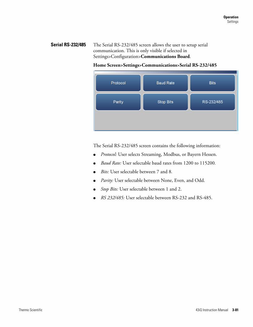
Operation Settings
Thermo Scientific 43iQ Instruction Manual 3-81
The Serial RS-232/485 screen allows the user to setup serial communication. This is only visible if selected in Settings>Configuration>Communications Board.
Home Screen>Settings>Communications>Serial RS-232/485
The Serial RS-232/485 screen contains the following information:
● Protocol: User selects Streaming, Modbus, or Bayern Hessen.
● Baud Rate: User selectable baud rates from 1200 to 115200.
● Bits: User selectable between 7 and 8.
● Parity: User selectable between None, Even, and Odd.
● Stop Bits: User selectable between 1 and 2.
● RS 232/485: User selectable between RS-232 and RS-485.
Serial RS-232/485
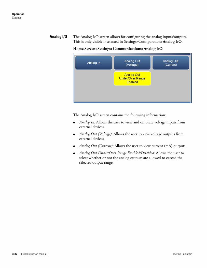
Operation Settings
3-82 43iQ Instruction Manual Thermo Scientific
The Analog I/O screen allows for configuring the analog inputs/outputs. This is only visible if selected in Settings>Configuration>Analog I/O.
Home Screen>Settings>Communications>Analog I/O
The Analog I/O screen contains the following information:
● Analog In: Allows the user to view and calibrate voltage inputs from external devices.
● Analog Out (Voltage): Allows the user to view voltage outputs from external devices.
● Analog Out (Current): Allows the user to view current (mA) outputs.
● Analog Out Under/Over Range Enabled/Disabled: Allows the user to select whether or not the analog outputs are allowed to exceed the selected output range.
Analog I/O

Operation Settings
Thermo Scientific 43iQ Instruction Manual 3-83
The Digital I/O screen allows for configuring the digital inputs/outputs. This is only visible if selected in Settings>Configuration>Digital I/O.
Home Screen>Settings>Communications>Digital I/O
The Digital I/O screen contains the following information:
● Digital In: Allows the user to view digital inputs from external devices.
● Digital Out (Relays): Allows the user to view relay outputs.
● Digital Out (Solenoids): Allows the user to view solenoid outputs.
● Advanced Digital I/O: Allows user to test the digital out relays and solenoids.
Digital I/O

Operation Settings
3-84 43iQ Instruction Manual Thermo Scientific
The Email Server (SMTP) screen allows the user to configure their email preferences.
Home Screen>Settings>Communications>Email Server (SMTP)
The Email Server (SMTP) screen contains the following information:
● SMTP Server Address: Address of the user’s email server.
● From Email Address: The email address that goes in the From field in emails.
● SMTP Server Port: Server port of user’s email server.
● Email Password: Password for SMTP server.
● Email UserName: User name that is authorized to send email through SMTP server.
Email Server (SMTP)
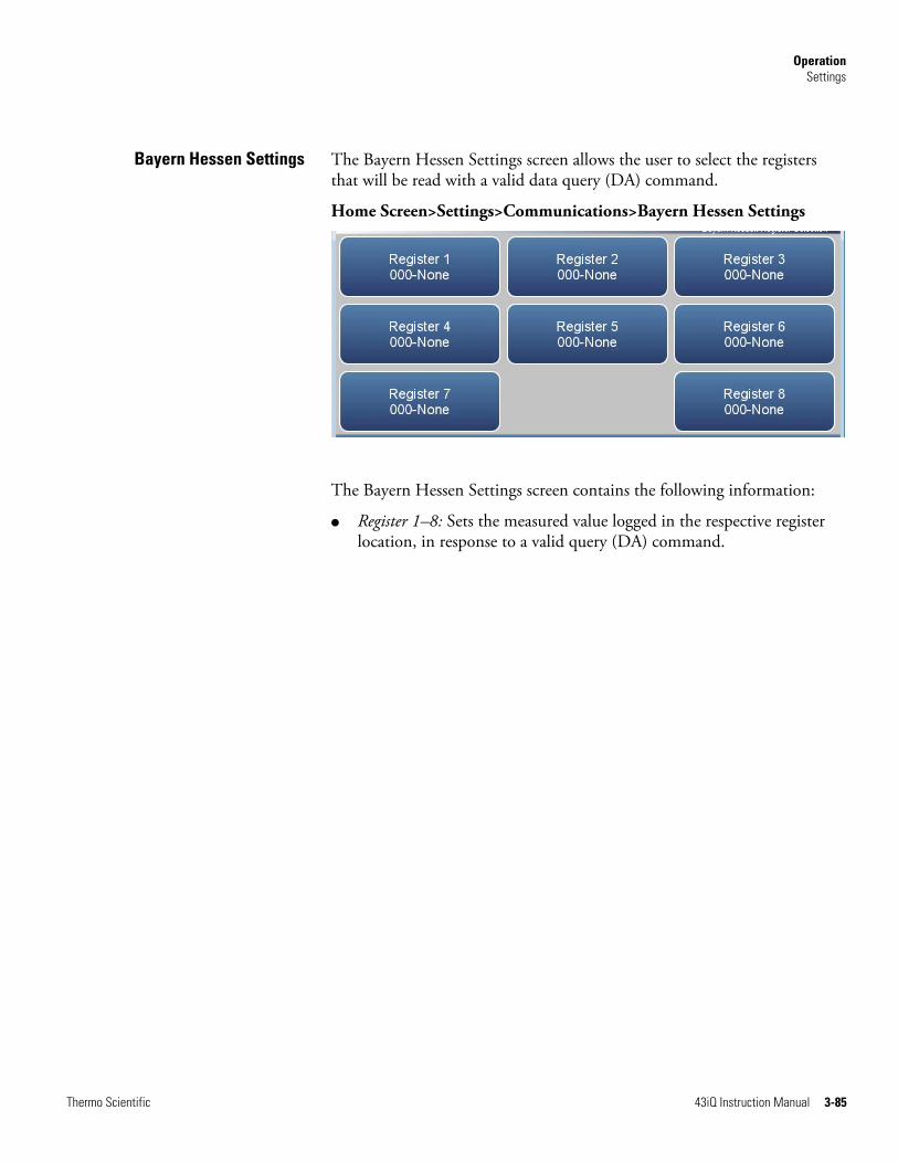
Operation Settings
Thermo Scientific 43iQ Instruction Manual 3-85
The Bayern Hessen Settings screen allows the user to select the registers that will be read with a valid data query (DA) command.
Home Screen>Settings>Communications>Bayern Hessen Settings
The Bayern Hessen Settings screen contains the following information:
● Register 1–8: Sets the measured value logged in the respective register location, in response to a valid query (DA) command.
Bayern Hessen Settings
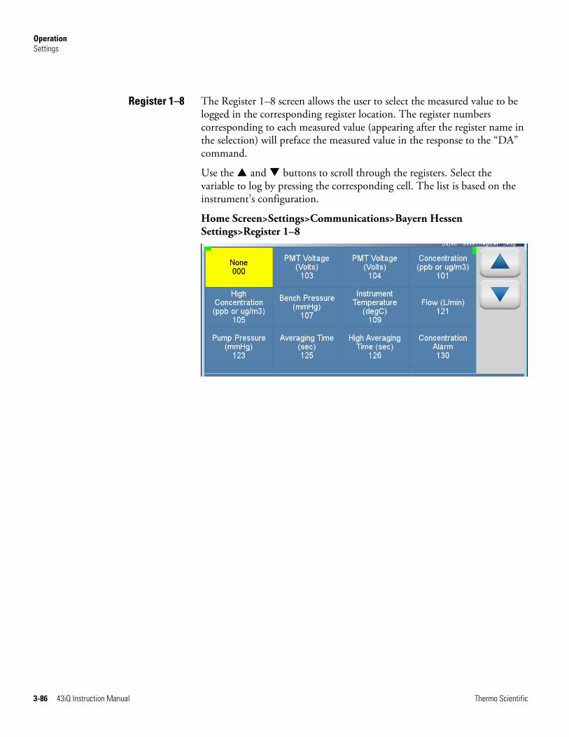
Operation Settings
3-86 43iQ Instruction Manual Thermo Scientific
The Register 1–8 screen allows the user to select the measured value to be logged in the corresponding register location. The register numbers corresponding to each measured value (appearing after the register name in the selection) will preface the measured value in the response to the “DA” command.
Use the and buttons to scroll through the registers. Select the variable to log by pressing the corresponding cell. The list is based on the instrument’s configuration.
Home Screen>Settings>Communications>Bayern Hessen Settings>Register 1–8
Register 1–8
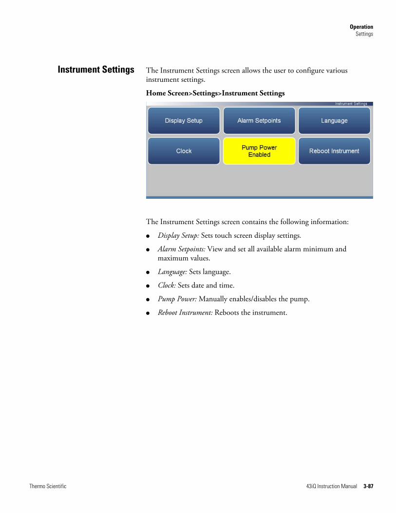
Operation Settings
Thermo Scientific 43iQ Instruction Manual 3-87
The Instrument Settings screen allows the user to configure various instrument settings.
Home Screen>Settings>Instrument Settings
The Instrument Settings screen contains the following information:
● Display Setup: Sets touch screen display settings.
● Alarm Setpoints: View and set all available alarm minimum and maximum values.
● Language: Sets language.
● Clock: Sets date and time.
● Pump Power: Manually enables/disables the pump.
● Reboot Instrument: Reboots the instrument.
Instrument Settings

Operation Settings
3-88 43iQ Instruction Manual Thermo Scientific
The Display Setup allows the user to change the brightness of the display and choose power save option.
Home Screen>Settings>Instrument Settings>Display Setup
The Display Setup screen contains the following information:
● Power Save: Minutes before screen times out. Toggles enable/disable.
● Power Save Setting: Option whereby the user can display a black screen after a set amount of inactivity.
● Brightness: Sets the brightness of the display.
Display Setup

Operation Settings
Thermo Scientific 43iQ Instruction Manual 3-89
The Alarm Setpoints screen allows the user to view and set all settable alarm minimum and maximum values.
Note User cannot set alarm limits outside of the acceptable range. The minimum and maximum alarm limit can also be set by pressing on the corresponding buttons located in the Settings>Health Check>Status and Alarms screen. See “Status and Alarms” on page 3-35. ▲
Use the and buttons to move up and down and the and buttons to move left and right.
Home Screen>Settings>Instrument Settings>Alarm Setpoints
The Alarm Setpoints screen contains the following information:
● Across:
● Variable: Lists the items that have settable alarm limits.
● Value: Displays the current value for each item.
● Low Alarm: User sets low alarm for item.
● High Alarm: User sets high alarm for item.
● Units: Units for each item (not settable).
● Down:
● SO2 Concentration: SO2 concentration alarm.
● Bkg Check Offset: User can set the maximum allowable background reading offset for calibration and calibration checks. This is set with the high alarm only.
Alarm Setpoints
Operation Settings
3-90 43iQ Instruction Manual Thermo Scientific
● Span Check Offset: User can set the maximum allowable span reading offset for calibration and calibration checks. This is set with the high alarm only.
● Chamber Temperature: Chamber temperature alarm.
● Lamp Intensity: Lamp intensity alarm.
● Lamp Voltage: Lamp voltage alarm.
● Instrument Temperature: Instrument temperature alarm.
● Bench Pressure: Bench pressure alarm.
● Flow: Flow pressure alarm.
● Perm Oven Temperature: Perm oven temperature alarm.
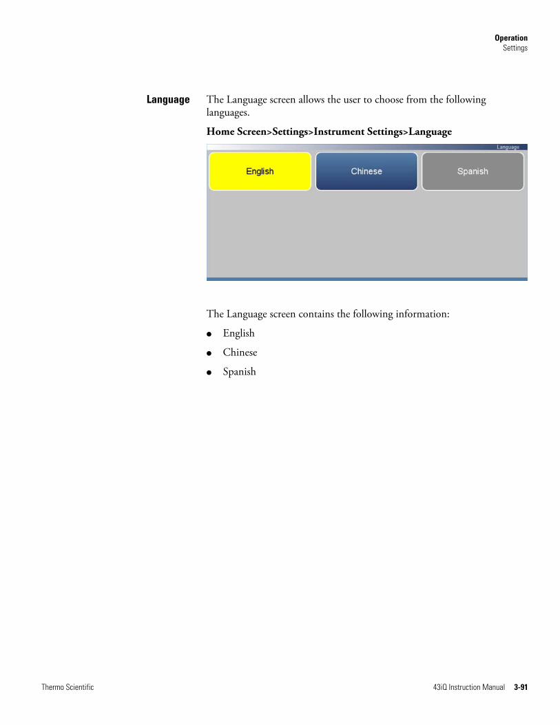
Operation Settings
Thermo Scientific 43iQ Instruction Manual 3-91
The Language screen allows the user to choose from the following languages.
Home Screen>Settings>Instrument Settings>Language
The Language screen contains the following information:
● English
● Chinese
● Spanish
Language
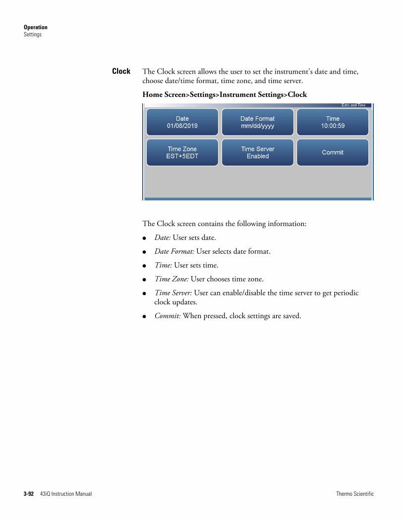
Operation Settings
3-92 43iQ Instruction Manual Thermo Scientific
The Clock screen allows the user to set the instrument’s date and time, choose date/time format, time zone, and time server.
Home Screen>Settings>Instrument Settings>Clock
The Clock screen contains the following information:
● Date: User sets date.
● Date Format: User selects date format.
● Time: User sets time.
● Time Zone: User chooses time zone.
● Time Server: User can enable/disable the time server to get periodic clock updates.
● Commit: When pressed, clock settings are saved.
Clock
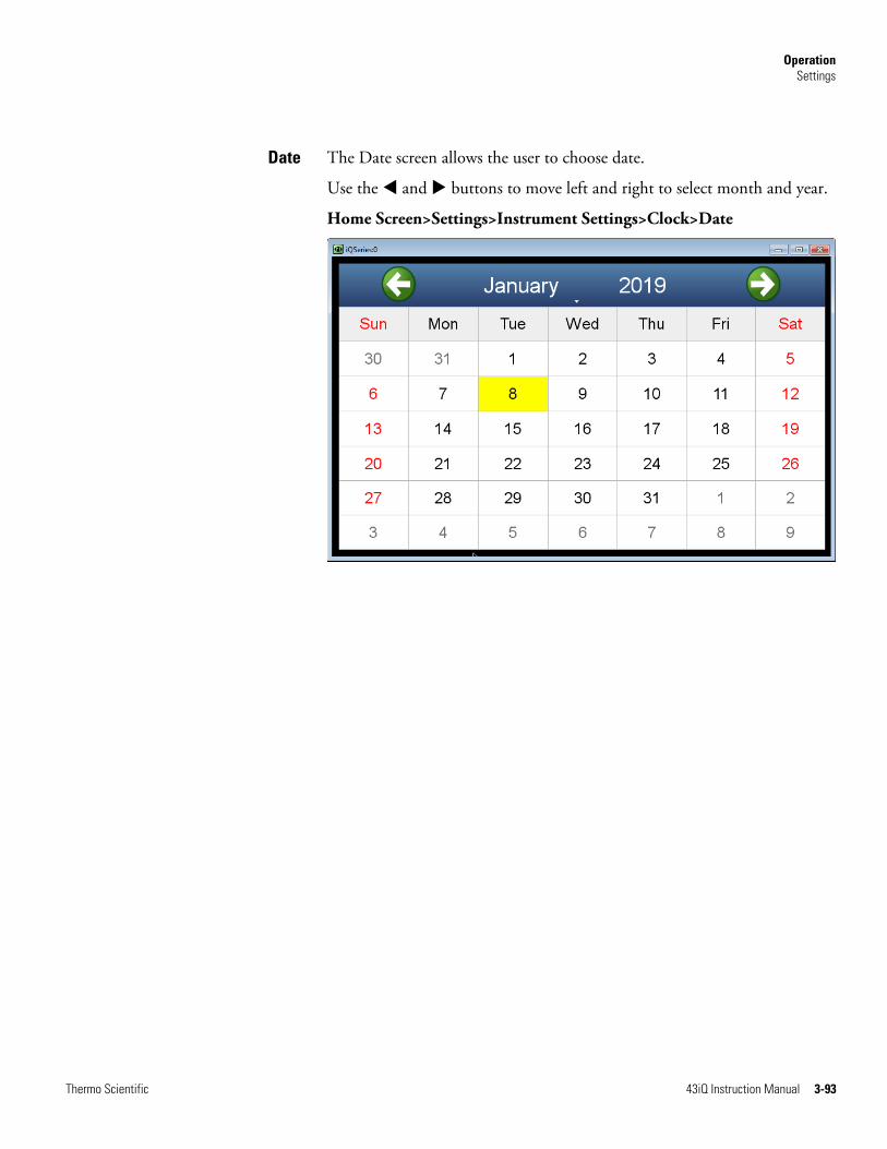
Operation Settings
Thermo Scientific 43iQ Instruction Manual 3-93
The Date screen allows the user to choose date.
Use the and buttons to move left and right to select month and year.
Home Screen>Settings>Instrument Settings>Clock>Date
Date

Operation Settings
3-94 43iQ Instruction Manual Thermo Scientific
The Date Format screen allows the user to choose from the following formats: mm/dd/yyyy or dd/mm/yyyy.
Use the and buttons to select.
Home Screen>Settings>Instrument Settings>Clock>Date Format
The Date Format screen contains the following information:
● U.S. Format mm/dd/yyyy
● European Format dd/mm/yyyy
● ISO 8601 yyyy-mm-dd
Date Format

Operation Settings
Thermo Scientific 43iQ Instruction Manual 3-95
The Time screen allows the user to choose from the following formats: mm/dd/yyyy or dd/mm/yyyy.
Use the and buttons to select.
Home Screen>Settings>Instrument Settings>Clock>Time
The Time screen contains the following information:
● Hours
● Minutes
● Seconds
Time

Operation Settings
3-96 43iQ Instruction Manual Thermo Scientific
The Time Zone screen allows the user to set the time zone for the Network Time Protocol (NTP) server. This should be set to the time zone that the instrument is located in.
Use the and buttons to select.
Home Screen>Settings>Instrument Settings>Clock>Time Zone
The Time Zone screen contains the following information:
● Date Line West(UTC-12)
● Samoa Time Zone(UTC-11)
● Aleutian Time Zone(UTC-10)
● Alaskan Time Zone(UTC-9)
● Pacific Time Zone(UTC-8)
● Pacific Daylight Savings(UTC-7)
● Mountain Time Zone(UTC-7)
● Mountain Daylight Savings(UTC-6)
● Central Time Zone(UTC-6)
● Central Daylight Savings((UTC-5)
● Eastern Time Zone(UTC-5)
● Eastern Daylight Savings(UTC-4)
● Atlantic Time Zone(UTC-4)
● Mid-Atlantic(UTC-3)
● South Georgia(UTC-2)
● Cape Verde Time(UTC-1)
Time Zone

Operation Settings
Thermo Scientific 43iQ Instruction Manual 3-97
● Coordinated Universal Time(UTC-0)
● Central European Time(UTC+1)
● Eastern European Time(UTC+2)
● Further-Eastern European Time(UTC+3)
● Gulf Standard Time(UTC+4)
● Yekaterinburg Time(UTC+5
● Omsk Time(UTC+6)
● Indochina Time(UTC+7)
● ASEAN Common Time(UTC+8)
● Japan Standard Time(UTC+9)
● Chamorro Time Zone(UTC+10)
● Sredmnekolymsk Time(UTC+11)
● New Zealand Standard Time(UTC+12)

Operation Settings
3-98 43iQ Instruction Manual Thermo Scientific
The Time Server screen allows the user to enable/disable the time server to get periodic clock updates.
Home Screen>Settings>Instrument Settings>Clock>Time Server
The Time Server screen contains the following information:
● Time Server: Enables/Disables periodic clock updates from an NTP (Network Time Protocol) source.
● Set Time Server: User can choose specific time server.
● Set Default: When pressed, default time server will be used.
Time Server

Operation Settings
Thermo Scientific 43iQ Instruction Manual 3-99
The Configuration screen allows the user to enable optional features. If an option is disabled, the corresponding buttons will be grayed out and the screens will not be available.
Use the and buttons to scroll through the variables. Select the variables to log by pressing the corresponding cells. Next, press the Commit Changes button to save selections. Yellow buttons indicate that the variable is selected. More than one can be chosen.
Home Screen>Settings>Configuration
The Configuration screen contains the following information:
● Zero/Span Assembly: Enables zero/span valves.
● Perm Oven: Enables permeation oven option.
● Analog I/O: Enables analog I/O option.
● Digital I/O: Enables digital I/O option.
● Communications Board: Enables RS-232 or RS-485 communication board option.
● Predictive Diagnostics: Enables predictive diagnostics.
● Instrument Warmup: Enables instrument warm up option.
● High Flow: Switches between standard and high flow options.
Configuration

Operation Settings
3-100 43iQ Instruction Manual Thermo Scientific
The Access Levels screen allows the user to set the instrument to either View Only or Full Access. When in Full Access, the user will have access to all screens. When set to View Only, user will not be able to change any values.
Home Screen>Settings>Security Access Levels (Full Access)
Home Screen>Settings>Security Access Levels (View Only Access)
The Security Access Levels screen contains the following information:
● Current Security Access Full Access: Read only. User will be able to change all values. Password is needed for full access.
● Current Security Access View Only: Read only. User won’t be able to change any values. Password is not needed for view only.
● Change Security Access to View Only: User can switch to view only mode. Password not needed to change settings to view only access.
● Change Security Access to Full Access: User can switch to full access mode. Password is needed to change settings to full access.
Security AccessLevels

Operation Settings
Thermo Scientific 43iQ Instruction Manual 3-101
● Change Full Access Security Password: Full access password can have a blank value or user selected password.

Operation Settings
3-102 43iQ Instruction Manual Thermo Scientific
The Change Security to View Only Access screen allows the user to set the instrument to view only.
Home Screen>Settings>Security Access Levels>Change Security Access to View Only Access
The Change Security to View Only Access screen contains the following information:
● Set Access Level to View Only: Programs the instrument to be in the view only access level, where the user won’t be able to change any values.
● Cancel: Exit screen.
Note To change security access from view only access to full access, a keypad will be displayed where the user can enter full access password. ▲
Change Security to ViewOnly Access
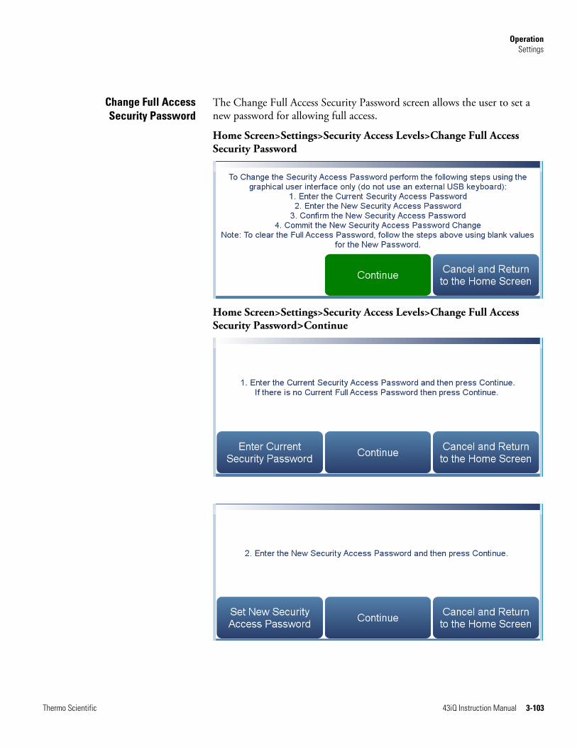
Operation Settings
Thermo Scientific 43iQ Instruction Manual 3-103
The Change Full Access Security Password screen allows the user to set a new password for allowing full access.
Home Screen>Settings>Security Access Levels>Change Full Access Security Password
Home Screen>Settings>Security Access Levels>Change Full Access Security Password>Continue
Change Full AccessSecurity Password

Operation Settings
3-104 43iQ Instruction Manual Thermo Scientific
The Change Full Access Security Password screens contain the following information:
● Enter Current Security Password: User enters current security password.
● Continue: Proceeds to next screen.
● Enter New Security Access Password: User enters new security password.
● Confirm New Security Access Password: User confirms new security password for spelling confirmation.
● Commit New Security Access Password Change: Commits new security password.
● Cancel and Return to the Home Screen: Exits screen and returns to the Home Screen without changing password.

Operation Settings
Thermo Scientific 43iQ Instruction Manual 3-105
The USB Drive screen allows the user to update firmware, download/upload information, and change the USB password.
Note The USB drive screen only is useable when a USB drive is inserted into the USB port. When a USB drive is inserted, the user is prompted to enter the password if a password has been set. ▲
Home Screen>Settings>USB Drive
The USB Drive screen contains the following information:
● Firmware Update Via USB Drive: If USB is mounted, user can update instrument firmware.
● Download Data To USB Drive: User can download/upload information.
● Change USB Password: User can change the USB password.
USB Drive
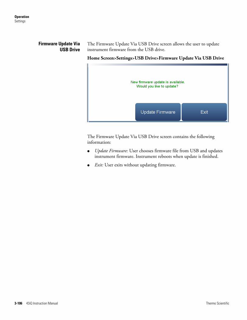
Operation Settings
3-106 43iQ Instruction Manual Thermo Scientific
The Firmware Update Via USB Drive screen allows the user to update instrument firmware from the USB drive.
Home Screen>Settings>USB Drive>Firmware Update Via USB Drive
The Firmware Update Via USB Drive screen contains the following information:
● Update Firmware: User chooses firmware file from USB and updates instrument firmware. Instrument reboots when update is finished.
● Exit: User exits without updating firmware.
Firmware Update ViaUSB Drive
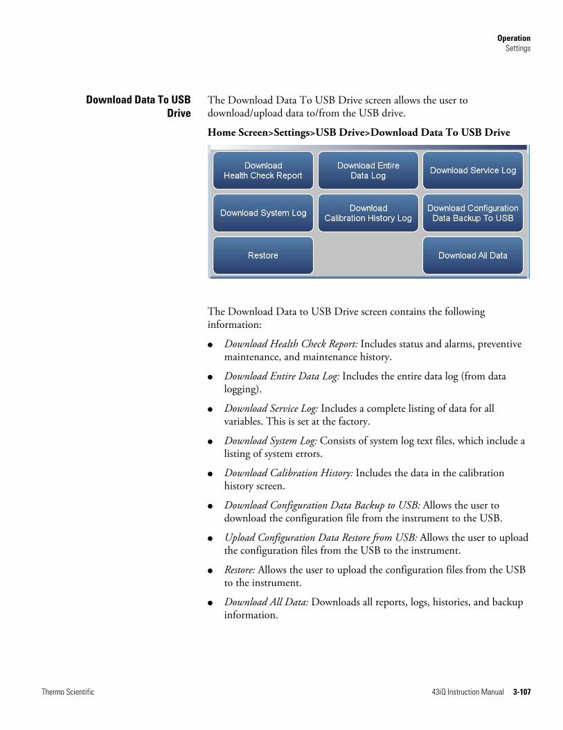
Operation Settings
Thermo Scientific 43iQ Instruction Manual 3-107
The Download Data To USB Drive screen allows the user to download/upload data to/from the USB drive.
Home Screen>Settings>USB Drive>Download Data To USB Drive
The Download Data to USB Drive screen contains the following information:
● Download Health Check Report: Includes status and alarms, preventive maintenance, and maintenance history.
● Download Entire Data Log: Includes the entire data log (from data logging).
● Download Service Log: Includes a complete listing of data for all variables. This is set at the factory.
● Download System Log: Consists of system log text files, which include a listing of system errors.
● Download Calibration History: Includes the data in the calibration history screen.
● Download Configuration Data Backup to USB: Allows the user to download the configuration file from the instrument to the USB.
● Upload Configuration Data Restore from USB: Allows the user to upload the configuration files from the USB to the instrument.
● Restore: Allows the user to upload the configuration files from the USB to the instrument.
● Download All Data: Downloads all reports, logs, histories, and backup information.
Download Data To USBDrive
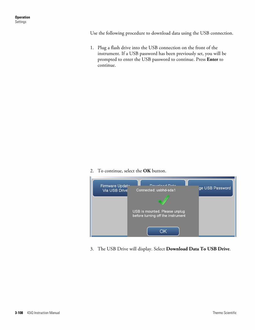
Operation Settings
3-108 43iQ Instruction Manual Thermo Scientific
Use the following procedure to download data using the USB connection.
1. Plug a flash drive into the USB connection on the front of the instrument. If a USB password has been previously set, you will be prompted to enter the USB password to continue. Press Enter to continue.
2. To continue, select the OK button.
3. The USB Drive will display. Select Download Data To USB Drive.
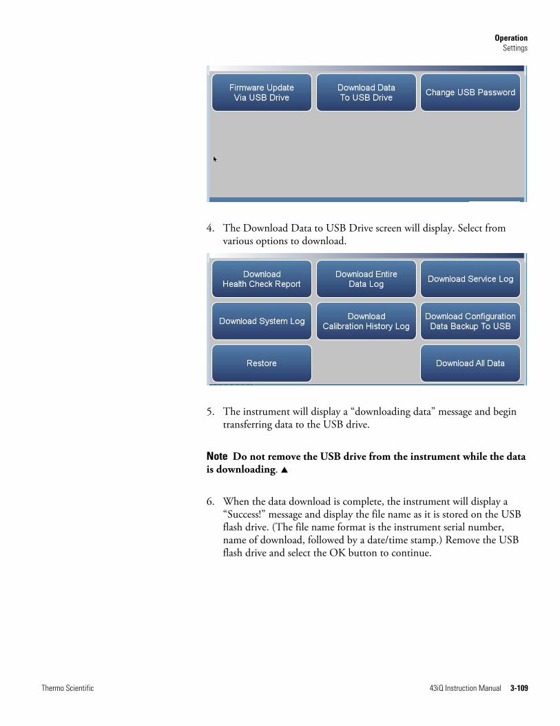
Operation Settings
Thermo Scientific 43iQ Instruction Manual 3-109
4. The Download Data to USB Drive screen will display. Select from various options to download.
5. The instrument will display a “downloading data” message and begin transferring data to the USB drive.
Note Do not remove the USB drive from the instrument while the data is downloading. ▲
6. When the data download is complete, the instrument will display a “Success!” message and display the file name as it is stored on the USB flash drive. (The file name format is the instrument serial number, name of download, followed by a date/time stamp.) Remove the USB flash drive and select the OK button to continue.

Operation Settings
3-110 43iQ Instruction Manual Thermo Scientific
The Change USB Password screen allows the user to set a new password for accessing USB.
Home Screen>Settings>USB Drive>Change USB Password
Home Screen>Settings>Security Access Levels>Change Standard Access Password>Continue
Change USB Password

Operation Settings
Thermo Scientific 43iQ Instruction Manual 3-111
The Change USB Password screens contain the following information:
● Enter Current USB Password: User enters current USB password.
● Continue: Proceeds to next screen.
● Enter New USB Password: User enters new USB password.
● Confirm New Security Access Password: User confirms new security password for spelling confirmation.
● Commit New USB Password Change: Commits new USB password.
● Cancel and Return to the Home Screen: Exits screen and returns to the Home Screen without changing password.

Operation Settings
3-112 43iQ Instruction Manual Thermo Scientific
The User Contact Information screen allows the user to enter their contact information. This is useful when contacting technical support through emails found at the screen Health Check>File Sharing and Support.
Home Screen>Settings>User Contact Information
The User Contact Information screen contains the following information:
● Business Name
● User Name
● Alternate User Name
● User ID
● Business Address
● Business Shipping Address
● To: User Email Address
● CC: User Email Address 110
● User Phone Number
● Alternate User Phone Number
● Shelter / Lab Phone Number
User ContactInformation
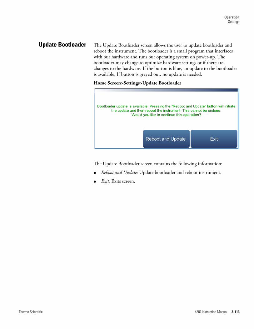
Operation Settings
Thermo Scientific 43iQ Instruction Manual 3-113
The Update Bootloader screen allows the user to update bootloader and reboot the instrument. The bootloader is a small program that interfaces with our hardware and runs our operating system on power-up. The bootloader may change to optimize hardware settings or if there are changes to the hardware. If the button is blue, an update to the bootloader is available. If button is greyed out, no update is needed.
Home Screen>Settings>Update Bootloader
The Update Bootloader screen contains the following information:
● Reboot and Update: Update bootloader and reboot instrument.
● Exit: Exits screen.
Update Bootloader

Thermo Scientific 43iQ Instruction Manual 4-1
Chapter 4
Calibration
This chapter describes the procedures for calibrating the analyzer and describes the required equipment.
The 43iQ requires initial and periodic calibration according to the procedures described in this chapter. A quality control plan that allows the frequency and number of calibration points to be modified depending on calibration and zero/span check data should be implemented. Such a quality control program is essential to ascertain the accuracy and reliability of the air quality data collected. The data compiled for such a program might include items such as dates of calibration, atmospheric conditions, control settings and other pertinent data. For more detailed quality assurance guidelines, see the Quality Assurance Handbook for Air Pollution Measurement Systems, published by the U.S. EPA, Research Triangle Park, NC, 27711.
There are a number of conditions which should be met prior to a calibration or a zero/span check. First, the instrument should have at least 30 minutes to warm up and stabilize. Second, the range used during the calibration or zero/span check should be the same as that used during normal monitoring. Third, all operational adjustments to the instrument should be completed prior to calibration. Fourth, all parts of the gas flow system, such as sample lines, and particulate filters, which are used in normal monitoring should also be used during calibration. Finally, it is recommended that the recording devices and outputs used during normal monitoring be calibrated prior to the instrument calibration and that they be used during the calibration or the zero/span check.
The following equipment is required to calibrate the instrument:
● Zero air
● Calibration gas
Note In order to reduce the possibility of interferences during calibration, all zero gas supplied to the instrument during calibrations should use air as the zero gas and not nitrogen. The same recommendation also applies to span gases supplied, where the calibration gas is supplied with a known SO2 concentration with the balance of gas as air and not nitrogen. ▲
Equipment Required
Calibration Equipment Required
4-2 43iQ Instruction Manual Thermo Scientific
An SO2-free (< 0.0005 ppb) air supply is required for the proper calibration and checkout of the instrument. There are several methods that are acceptable to generate this zero air.
Commercial heatless air dryers filled with a mixed bed of activated charcoal and a 13X molecular sieve have been found effective in removing SO2 from compressed air. The use of this type of zero gas system is recommended when minimum maintenance is of prime importance. This system requires a source of compressed air. Refer to the manufacturer’s recommendations for installation of such a system.
An absorbing column packed with activated charcoal is acceptable for scrubbing SO2 from ambient air. Ambient air is forced through a laboratory gas absorption column packed with the charcoal and the SO2 is removed to acceptable levels (<0.0005 ppb). The charcoal should be changed at a minimum of every six months. It may be necessary to change the charcoal more frequently depending on local conditions.
A cylinder of SO2 in air containing an appropriate concentration of SO2 suitable for the selected operating range of the analyzer under calibration is necessary. The assay of the cylinder must be traceable either to a National Institute of Standards and Technology (NIST) SO2 in Air Standard Reference Material (SRM) or an NIST/EPA approved gas manufacturer's Certified Reference Material (CRM).
A recommended protocol for certifying SO2 gas cylinders against a SO2, SRM or CRM is given in the Quality Assurance Handbook1. The SO2 gas cylinder should be recertified on a regular basis determined by the local quality control program.
A calibration gas system capable of providing accurate levels of SO2 calibration gas between zero and 80% of the full-scale range is required. The calibration system must provide a flow rate of at least 0.5 LPM for an instrument with the standard flow (instruments with higher flow rates will require a higher minimum calibration system flow rate). All calibration gas should be derived from local or working standards (such as cylinders of compressed gas or permeation devices) that are certified as traceable to an NIST primary standard.
Zero Air Generation
Commercial Heatless AirDryers
Absorbing Column
SO2 ConcentrationStandard
Calibration GasGeneration
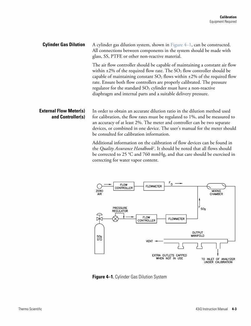
Calibration Equipment Required
Thermo Scientific 43iQ Instruction Manual 4-3
A cylinder gas dilution system, shown in Figure 4–1, can be constructed. All connections between components in the system should be made with glass, SS, PTFE or other non-reactive material.
The air flow controller should be capable of maintaining a constant air flow within ±2% of the required flow rate. The SO2 flow controller should be capable of maintaining constant SO2 flows within ±2% of the required flow rate. Ensure both flow controllers are properly calibrated. The pressure regulator for the standard SO2 cylinder must have a non-reactive diaphragm and internal parts and a suitable delivery pressure.
In order to obtain an accurate dilution ratio in the dilution method used for calibration, the flow rates must be regulated to 1%, and be measured to an accuracy of at least 2%. The meter and controller can be two separate devices, or combined in one device. The user's manual for the meter should be consulted for calibration information.
Additional information on the calibration of flow devices can be found in the Quality Assurance Handbook1. It should be noted that all flows should be corrected to 25 °C and 760 mmHg, and that care should be exercised in correcting for water vapor content.
Figure 4–1. Cylinder Gas Dilution System
Cylinder Gas Dilution
External Flow Meter(s)and Controller(s)
Calibration Equipment Required
4-4 43iQ Instruction Manual Thermo Scientific
The exact SO2 concentration is calculated from:
F + F
F x ]SO[ = ]SO[
SOD
SOSTD2OUT2
2
2
Where:
[SO2]OUT = diluted SO2 concentration at the output manifold, ppm
[SO2]STD = concentration of the undiluted SO2 standard, ppm
FSO2 = flow rate of the SO2 standard corrected to 25 C and 760 mm Hg
FD = flow rate of the dilution air corrected to 25 C and 760 mm Hg
Commercial precision dilution systems are available which reliably and accurately dilute a high concentration gas mixture to provide a reliable span gas. A high concentration (50 ppm) of SO2 in air is precisely diluted to the concentration range required.
The Thermo Scientific 146iQ Multi-gas Calibrator is one such system for precision dilution.
Permeation tube systems which precisely maintain a set temperature to within ±0.1 °C and hold a zero air flow rate to within ±0.5% can be used for generation of span gas. The flow rate of the permeation system must be at least 0.5 LPM for proper operation.
A permeation tube system, shown in Figure 4–2 can be constructed. All connections between components in the system should be made with glass, PTFE, or other non-reactive material.
The air flow controllers should be capable of maintaining a constant air flow within ±2% of the required flow rate. Ensure all devices are properly calibrated and that all flows are corrected to 25 C and 1 atm.
Commercial PrecisionDilution Systems
Permeation Tube System

Calibration Equipment Required
Thermo Scientific 43iQ Instruction Manual 4-5
Figure 4–2. Permeation Tube System
The SO2 output level is calculated from:
F
K x P = ]SO[
TOUT2
Where:
[SO2]OUT = SO2 output concentration in ppm
P = permeation rate in μg/min
FT = total flow rate of gas after mixing chamber (FP + FD) in liters/minute
K (SO2) = 0.382 constant for SO2 permeant
Commercial permeation systems, such as the Thermo Scientific 146iQ Multigas Calibration System, are available for this requirement. Refer to the instrument instruction manual for more information.
In addition to the 146iQ and other commercial permeation systems, the 43iQ can also be configured with an optional permeation oven to supply calibration gas for the instrument. The operation of the internal permeation oven is described in Chapter 9, “Optional Equipment”.
Commercial PermeationSystems

Calibration Calibration
4-6 43iQ Instruction Manual Thermo Scientific
Regulations typically require zero/span calibration when the instrument is newly installed, moved, repaired, interrupted for more than a few days, or when span or zero shift by more than 15%.
All gas must be supplied to the instrument at atmospheric pressure. It may be necessary to employ an atmospheric bypass plumbing arrangement to accomplish this. Refer to Figure 2–6 in the “Installation and Setup” chapter for an example of an atmospheric bypass plumbing arrangement.
If a filter is used, all gas must enter the instrument through the filter.
Note The calibration and calibration check duration times should be long enough to account for the transition (purge) process when switching from sample to zero and from zero to span. This transition time is the time required to purge the existing air. ▲
Depending on the plumbing configuration and the instrument, data from approximately the first minute of a zero calibration or check should be disregarded because of residual sample air. Also, data from approximately the first minute of a span calibration or check should be disregarded because the span is mixing with the residual zero air. ▲
Use the following procedure to perform a zero/span calibration.
1. If the instrument is equipped with the optional zero/span and sample valves, connect the zero and span gas to the rear panel bulkheads labeled ZERO IN and SPAN, otherwise connect a source of vented zero air to the SAMPLE bulkhead. The top right of the title bar indicates which mode is active: ZERO, SPAN, or SAMPLE.
Note Do not use nitrogen for zero air. ▲
2. To ensure that the zero air is being measured at atmospheric pressure, check that the zero air flow reported by the analyzer is approximately 0.5 LPM. Actual zero air flow should be 0.8 LPM or more, with the excess flowing out the atmospheric bypass.
a. From the Home screen choose Settings>Health Check>Status and Alarms>Flow and Pressure.
b. Make sure that the reported sample flow is less than the actual zero air flow.
Calibration

Calibration Calibration
Thermo Scientific 43iQ Instruction Manual 4-7
3. Monitor the zero air reading and wait for the reading to stabilize.
4. From the Home Screen, press Calibration>Calibrate Background.
The Target Concentration button will read 0.00. The Calculated Background button will display the background needed to make the current SO2 concentration go to 0.00.
5. Press Calibrate to set the SO2 reading to zero and to save the new background.
6. Connect a source of calibration gas to the SAMPLE bulkhead. The calibration gas concentration should be approximately 80% of the full-scale range.
7. To ensure that the calibration gas is being measured at atmospheric pressure, check that the sample flow in the analyzer is approximately 0.5 LPM. Actual sample air flow should be 0.8 LPM or more, with the excess flowing out the atmospheric bypass.
8. Sample the vented calibration gas and wait for the instrument reading to stabilize.
9. From the Home Screen, choose Calibration>Calibrate Span Coefficient.
The user sets the span concentration by pressing the Edit Span Concentration button. The Calculated Span Coefficient button will show what the span coefficient will be set to if the Calibrate button is pressed. Pressing the Calibrate button will save the new coefficient and calibrate the instrument.
10. Enter the SO2 calibration gas concentration using the pushbuttons, and then press Calibrate to calibrate the instrument to the SO2 calibration gas.
Note The minimum and maximum analog output configuration values should be set to the default settings (minimum 0%; maximum 100%). ▲

Calibration Calibration in Dual/Auto Range Mode
4-8 43iQ Instruction Manual Thermo Scientific
Regulations typically require zero/span calibration when the instrument is newly installed, moved, repaired, interrupted for more than a few days, or when span or zero shift by more than 15%.
All gas must be supplied to the instrument at atmospheric pressure. It may be necessary to employ an atmospheric bypass plumbing arrangement to accomplish this. Refer to Figure 2–6 in the “Installation and Setup” chapter for an example of an atmospheric bypass plumbing arrangement.
If a filter is used, all gas must enter the instrument through the filter.
Note The calibration and calibration check duration times should be long enough to account for the transition (purge) process when switching from sample to zero and from zero to span. This transition time is the time required to purge the existing air. ▲
Depending on the plumbing configuration and the instrument, data from approximately the first minute of a zero calibration or check should be disregarded because of residual sample air. Also, data from approximately the first minute of a span calibration or check should be disregarded because the span is mixing with the residual zero air. ▲
Use the following procedure to perform a zero/span calibration.
1. If the instrument is equipped with the optional zero/span and sample valves, connect the zero and span gas to the rear panel bulkheads labeled ZERO IN and SPAN, otherwise connect a source of vented zero air to the SAMPLE bulkhead. The top right of the title bar indicates which mode is active: Zero, Span, or Sample.
Note Do not use nitrogen for zero air. ▲
2. To ensure that the zero air is being measured at atmospheric pressure, check that the zero air flow reported by the analyzer is approximately 0.5 LPM. Actual zero air flow should be 0.8 LPM or more, with the excess flowing out the atmospheric bypass.
a. From the Home screen choose Settings>Health Check>Status and Alarms>Flow and Pressure.
b. Make sure that the reported sample flow is less than the actual zero air flow.
Calibration inDual/Auto Range
Mode

Calibration Calibration in Dual/Auto Range Mode
Thermo Scientific 43iQ Instruction Manual 4-9
3. Monitor the zero air reading and wait for the reading to stabilize.
4. From the Home Screen, choose Calibration>Calibrate Background.
The Target Concentration button will read 0.000. The Calculated Background button will display the background needed to make the current SO2 concentration go to zero.
5. Press Calibrate to set the SO2 reading to zero and to save the new background.
6. Connect a source of calibration gas to the SAMPLE bulkhead. The calibration gas concentration should be approximately 80% of the high full-scale range.
7. To ensure that the calibration gas is being measured at atmospheric pressure, check that the sample flow in the analyzer is approximately 0.5 LPM. Actual sample air flow should be 0.8 LPM or more, with the excess flowing out the atmospheric bypass.
8. Sample the vented calibration gas and wait for the instrument reading to stabilize.
9. From the Home Screen, choose Calibration>Calibrate High Range Span Coefficient.
The user sets the span concentration by pressing the Edit High Range Span Concentration button. The Calculated High Span Coefficient button will show what the high range span coefficient will be set to if the Calibrate button is pressed. Pressing the Calibrate button will save the new high range coefficient and calibrate the instrument.
10. Enter the SO2 calibration gas concentration using the pushbuttons, and then press Calibrate to calibrate the instrument to the high SO2 calibration gas.
Note The minimum and maximum analog output configuration values should be set to the default settings (minimum 0%; maximum 100%). ▲
11. Connect a source of calibration gas to the SAMPLE bulkhead. The calibration gas concentration should be approximately 80% of the low full-scale range.

Calibration Zero and Span Check
4-10 43iQ Instruction Manual Thermo Scientific
12. From the Home Screen, choose Calibration>Calibrate Low Range Span Coefficient.
The user sets the span concentration by pressing the Edit Low range Span Concentration button. The Calculated Low Range Span Coefficient button will show what the low span coefficient will be set to if the Calibrate button is pressed. Pressing the Calibrate button will save the new low range coefficient and calibrate the instrument.
13. Enter the SO2 calibration gas concentration using the pushbuttons, and then press Calibrate to calibrate the instrument to the low range SO2 calibration gas.
The zero and span check procedure is normally performed any time a quick check of the accuracy of the instrument is required. Normally, zero and span are checked daily. As experience is gained with the instrument, the frequency of these checks can be adjusted accordingly.
The span gas concentration used in the span check should be between 70% and 90% of the full-scale range. The zero and span drift should be measured and recorded prior to making any adjustments.
All gas must be supplied to the instrument at atmospheric pressure. It will be necessary to employ an atmospheric bypass plumbing arrangement to accomplish this.
If a filter is used, all gas must enter the instrument through the filter.
Use the following procedure to check the zero/span.
1. If the instrument is equipped with the optional zero/span and sample valves, connect the zero and span gas to the rear panel bulkheads labeled ZERO IN and SPAN, otherwise connect a source of vented zero air to the SAMPLE bulkhead.
Note Do not use nitrogen for zero air. ▲
2. To ensure that the zero air is being measured at atmospheric pressure, check that the zero air flow reported by the analyzer is approximately 0.5 LPM. Actual zero air flow should be 0.8 LPM or more, with the excess flowing out the atmospheric bypass.
a. From the Home screen choose Settings>Health Check>Status and Alarms>Flow and Pressure.
Zero and Span Check
Calibration Manual Calibration
Thermo Scientific 43iQ Instruction Manual 4-11
b. Make sure that the reported sample flow is less than the actual zero air flow.
3. Monitor the zero air reading and wait for the reading to stabilize.
4. Record the measured SO2 value as the zero drift since the last adjustment. If the zero has changed by more than ±0.015 ppm, it is recommended that a new calibration be performed.
5. Connect a source of vented span gas to the SAMPLE bulkhead. The span gas should be approximately 80% of the full-scale range.
6. To ensure that the span gas is being measured at atmospheric pressure check that the flow is approximately 0.5 LPM or more, with the excess flowing out the atmospheric bypass.
7. Sample the vented calibration gas and wait for the instrument reading to stabilize.
8. Record the difference between the measured SO2 value and the actual SO2 span concentration used. This is the span drift since the last adjustment. If the calibration has changed by more than ±10%, a new calibration should be performed.
The Manual Calibration screen allows the user to view and manually adjust the zero background and span coefficient. These are used to correct the SO2 readings that the instrument generates using its own internal calibration data.
Normally, the zero background and span coefficient are calculated automatically at the Calibrate Background and Calibrate Span Coefficient described earlier in the chapter. However, the calibration factors can also be set manually using the functions as described below.
The following screen is shown in single range mode. In dual or auto range modes, “High Range” or “Low Range” buttons are displayed to indicate the calibration of the high or low coefficient. The Adjust High Range Span Coefficient and Adjust Low Range Span Coefficient screens function the same way.
Manual Calibration

Calibration Manual Calibration
4-12 43iQ Instruction Manual Thermo Scientific
Home Screen>Calibration>Advanced Calibration>Manual Calibration (single range mode)
The SO2 background is the amount of signal read by the analyzer while sampling zero air.
The Adjust Background screen is used to perform a manual zero background calibration of the instrument. As such, the instrument should sample zero air until stable readings are obtained. The button labeled Adjust Background allows the user to change zero background. The second button called Adjusted Concentration shows what the new SO2 concentration would be based on the changed zero background. Press the Calibrate button to save the adjusted zero background value.
Home Screen>Calibration>Advanced Calibration>Manual Calibration>Adjust Background
The span coefficient is used to correct the SO2 readings and normally has a value near 1.000 with minimum/maximum limits of 0.500 and 2.000 respectively.
The user can manually change the span coefficient by entering a value in the Adjust Span Concentration button. The second button called Adjusted
Adjust Background
Adjust SpanCoefficient
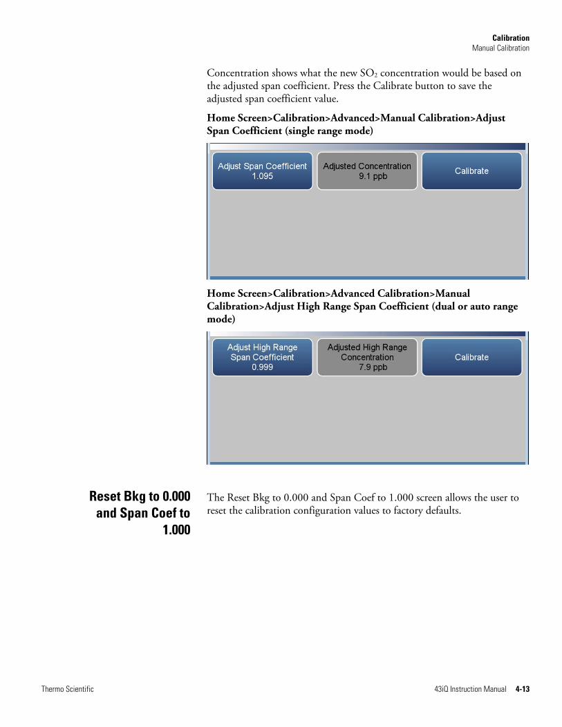
Calibration Manual Calibration
Thermo Scientific 43iQ Instruction Manual 4-13
Concentration shows what the new SO2 concentration would be based on the adjusted span coefficient. Press the Calibrate button to save the adjusted span coefficient value.
Home Screen>Calibration>Advanced>Manual Calibration>Adjust Span Coefficient (single range mode)
Home Screen>Calibration>Advanced Calibration>Manual Calibration>Adjust High Range Span Coefficient (dual or auto range mode)
The Reset Bkg to 0.000 and Span Coef to 1.000 screen allows the user to reset the calibration configuration values to factory defaults.
Reset Bkg to 0.000 and Span Coef to
1.000
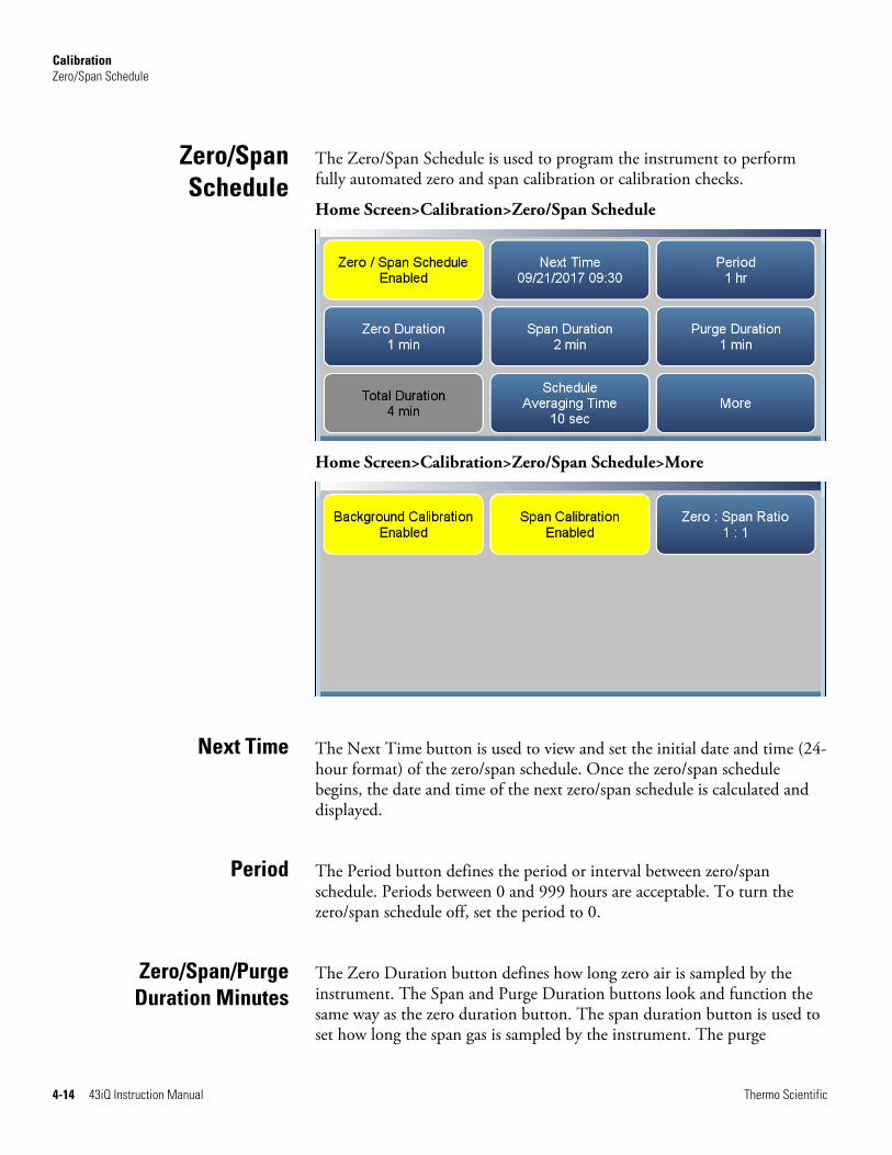
Calibration Zero/Span Schedule
4-14 43iQ Instruction Manual Thermo Scientific
The Zero/Span Schedule is used to program the instrument to perform fully automated zero and span calibration or calibration checks.
Home Screen>Calibration>Zero/Span Schedule
Home Screen>Calibration>Zero/Span Schedule>More
The Next Time button is used to view and set the initial date and time (24-hour format) of the zero/span schedule. Once the zero/span schedule begins, the date and time of the next zero/span schedule is calculated and displayed.
The Period button defines the period or interval between zero/span schedule. Periods between 0 and 999 hours are acceptable. To turn the zero/span schedule off, set the period to 0.
The Zero Duration button defines how long zero air is sampled by the instrument. The Span and Purge Duration buttons look and function the same way as the zero duration button. The span duration button is used to set how long the span gas is sampled by the instrument. The purge
Zero/SpanSchedule
Next Time
Period
Zero/Span/PurgeDuration Minutes

Calibration References
Thermo Scientific 43iQ Instruction Manual 4-15
duration button is used to set how long the purge period will be after doing a zero and/or span. This gives the instrument time to flush out the zero and span gas before any meaningful sample data is taken. Logged data is flagged as taken during a purge to show that the data is suspect. Durations between 0 and 99 minutes are acceptable. Each time a zero/span schedule occurs the zero is done first, followed by the span. To perform just a zero, set the span duration to 0 (off). The same applies to perform just a span.
The Schedule Averaging Time button allows the user to adjust the schedule averaging time. The schedule averaging time is used by the analyzer only when performing a zero/span schedule. The analyzer’s averaging time is used for all other functions. Range is 1300 seconds.
Background Calibration and Span Calibration are toggle buttons that change between enabled or disabled.
If the background calibration is set to enabled, then a zero adjustment is made. If the span calibration is set to enabled, then a span adjustment is made. (This is how to set up a scheduled, recurring auto calibration.)
The Zero/Span Ratio button is used to set the ratio of zero checks or adjustments to span checks or adjustments. For example, if this value is set to 1, a span duration will follow every zero duration. If this value is set to 3, there will be two zero checks between each span check. This value may be set from 1 to 99, with 1 as default.
1. Section 12 of EPA Quality Assurance Handbook for Air Pollution Measurement Systems, Volume II, available at www.epa.gov.
Section 12 also provides information on “Calibration of Primary and Secondary Standards for Flow Measurements”.
Specific information on certification of concentration standards is given in EPA Traceability Protocol for Assay and Certification of Gaseous Calibration Standards, available at www.epa.gov.
Schedule AveragingTime
BackgroundCalibration and
Span Calibration
Zero/Span Ratio
References


Thermo Scientific 43iQ Instruction Manual 5-1
Chapter 5
Maintenance
This chapter describes the periodic maintenance procedures that should be performed on the instrument to ensure proper operation. Since usage and environmental conditions vary greatly, you should inspect the components frequently until an appropriate maintenance schedule is determined.
Read the safety precautions before beginning any procedures in this chapter.
Equipment Damage Some internal components can be damaged by small amounts of static electricity. A properly grounded antistatic wrist strap must be worn while handling any internal component. For more information about appropriate safety precautions, see the “Servicing” chapter. ▲
Use the following procedure to inspect and clean the fan filter.
1. Remove the fan guard from the fan and remove the filter.
2. Flush the filter with warm water and let dry (a clean, oil-free purge will help the drying process) or blow the filter clean with compressed air.
3. Re-install the filter and fan guard.
Safety Precautions
Fan Filter Inspectionand Cleaning
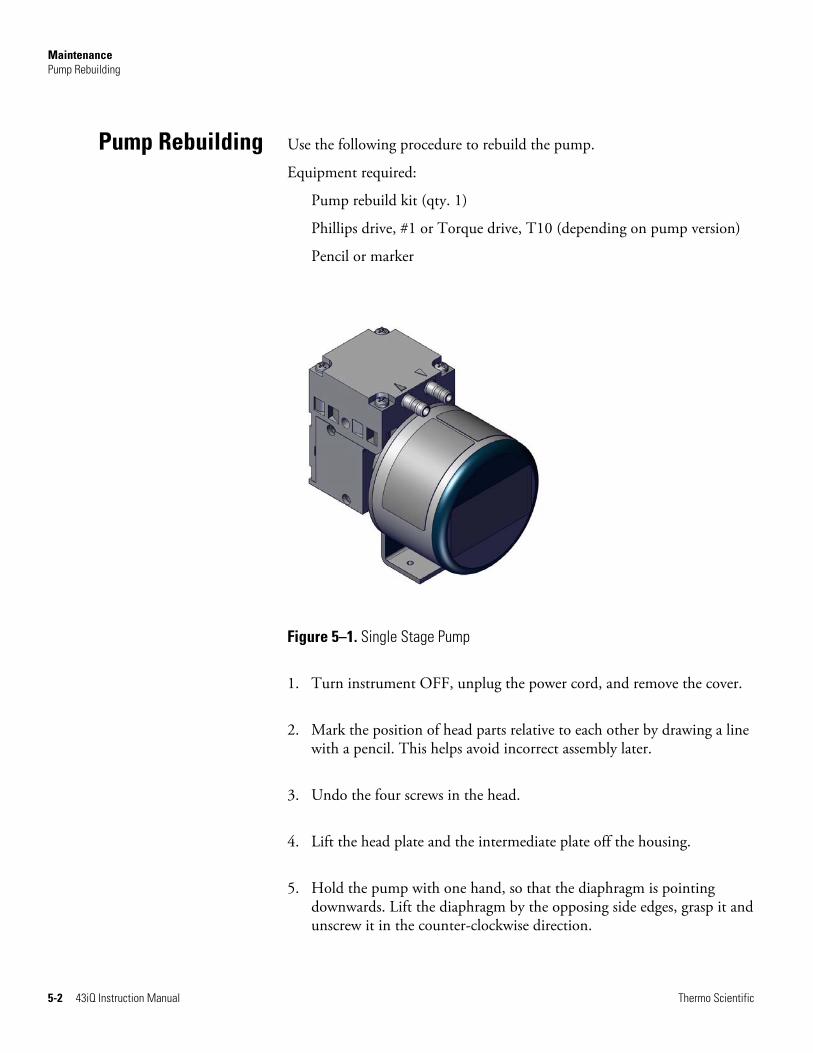
Maintenance Pump Rebuilding
5-2 43iQ Instruction Manual Thermo Scientific
Use the following procedure to rebuild the pump.
Equipment required:
Pump rebuild kit (qty. 1)
Phillips drive, #1 or Torque drive, T10 (depending on pump version)
Pencil or marker
Figure 5–1. Single Stage Pump
1. Turn instrument OFF, unplug the power cord, and remove the cover.
2. Mark the position of head parts relative to each other by drawing a line with a pencil. This helps avoid incorrect assembly later.
3. Undo the four screws in the head.
4. Lift the head plate and the intermediate plate off the housing.
5. Hold the pump with one hand, so that the diaphragm is pointing downwards. Lift the diaphragm by the opposing side edges, grasp it and unscrew it in the counter-clockwise direction.
Pump Rebuilding

Maintenance Pump Rebuilding
Thermo Scientific 43iQ Instruction Manual 5-3
6. Remove connection rod disc and diaphragm spacers from the threaded pin of the diaphragm.
7. Push the connection rod disc and the diaphragm spacers in this order onto the threaded pin of the new diaphragm.
8. Move the connecting rod to the upper point.
9. Screw the new diaphragm with connection rod disc and spacers clockwise onto the connection rod and tighten hand-tight.
10. Place the intermediate plate on housing, in the position indicated by the drawing line.
11. Place the new valve plate on the intermediate plate.
12. Place the head plate on the intermediate plate, in the position indicated by the drawing line; gently tighten the four screws, evenly and diagonally (if a torque screwdriver is available: torque about 0.30 Nm).
13. Let the pump run.

Maintenance Pump Rebuilding
5-4 43iQ Instruction Manual Thermo Scientific
Figure 5–2. Pump Rebuilding

Maintenance Leak Test
Thermo Scientific 43iQ Instruction Manual 5-5
Use the following procedure to perform a leak test.
Equipment Required:
Cap
Vacuum Tester with Gauge (with a resolution of .5 in Hg or better)
1. Turn instrument OFF, unplug the power cord.
2. Block the SAMPLE bulkhead on the rear panel with a leak-tight cap.
3. Connect the vacuum tester tool to the EXHAUST bulkhead on the rear panel.
4. Squeeze trigger until gauge reads to pull in 10 in Hg.
5. Observe vacuum gauge for stable reading for 5 minutes. If reading remains at 10 in Hg, no leak is present.
Note Acceptable leak rate is .5 in Hg over 10 minutes. ▲
Leak Test

Maintenance Lamp Voltage Check
5-6 43iQ Instruction Manual Thermo Scientific
The instrument is equipped with a lamp voltage control circuit, which automatically corrects for degradation of the flash lamp. However, after several years of use, the lamp may have degraded to the point that is being driven with the maximum voltage that the power supply can deliver.
There are two methods available that allows the operator to check the lamp voltage. The first is via the Measurements Settings>Advanced Measurement Settings>Optical Bench Settings>Continue to Detector Gain Settings Screen. The current Lamp Voltage and Lamp Intensity are displayed.
The second method is via Settings>Health Check>Status and Alarms>SO2 Bench screen. The current Lamp Voltage and Lamp Intensity are displayed along with the upper and lower alarm limits.
For detailed information about this screen, refer to the “Operation” chapter. For more information about replacing the lamp or adjusting the lamp voltage control circuit, see the “Servicing” chapter.
The auto calibration of the detector will automatically adjust the lamp voltage to 800 volts (±5 Volts). This is done so by adjusting the gain on the detector to optimize the illumination of the lamp.
Use the following procedure to adjust the lamp voltage.
1. From the Home screen choose Settings>Measurement Settings>Advanced Measurement Settings>Optical Bench Settings>Continue To Detector Gain Settings Screen.
2. Under the Detector Gain – Auto Cal, Press “Start” to initiate the auto calibration sequence.
Lamp VoltageCheck
Lamp VoltageAdjustment

Maintenance Lamp Voltage Adjustment
Thermo Scientific 43iQ Instruction Manual 5-7
3. To manually adjust the detector gain, touch the numeral value under the detector gain. Then change the Manual Entry Detector Gain to your set value and save.


Thermo Scientific 43iQ Instruction Manual 6-1
Chapter 6
Troubleshooting
This chapter presents guidelines for diagnosing analyzer failures, isolating faults, and includes recommended actions for restoring proper operation.
Read the safety precautions in Appendix A, “Safety” before performing any actions listed in this chapter.
Table 6–1 provides general troubleshooting information for the common platform and indicates the checks that you should perform if you experience an instrument problem. It also lists 43iQ specific troubleshooting information and alarm messages you may see on the graphics display and provides recommendations about how to resolve the alarm condition.
Table 6–1. 43iQ Troubleshooting Guide
Problem Possible Cause Action
Instrument does not start (LEDs on front panel do not come on and display is blank)
No power Verify that the power cord is plugged in, power is available and that it matches the voltage and frequency configuration of the instrument.
Fuse is blown or missing Disconnect power and check fuses with a volt meter.
Bad switch or wiring connection to switch
Check for 24V @ J9 on the Backplane board (middle pins). Check all wiring connections.
Front panel display does not start (LEDs on front panel are off)
Disconnected ribbon cable Power down and evaluate connections of display ribbon cable.
Front panel display does not start (LEDs on front panel are on)
Defective Display Connect to the instrument using ePort. Select “Remote Interface”. If normal GUI is displayed, replace defective display.
Front panel display stays white after power up (LEDs
Unseated or missing Micro SD card
Power off, re-seat Micro SD or install if missing.
Safety Precautions
TroubleshootingGuide
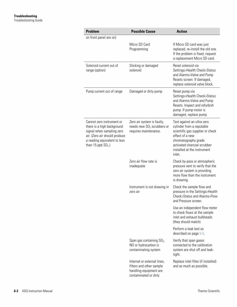
Troubleshooting Troubleshooting Guide
6-2 43iQ Instruction Manual Thermo Scientific
Problem Possible Cause Action
on front panel are on)
Micro SD Card Programming
If Micro SD card was just replaced, re-install the old one. If the problem is fixed, request a replacement Micro SD card.
Solenoid current out of range (option)
Sticking or damaged solenoid
Reset solenoid via Settings>Health Check>Status and Alarms>Valve and Pump Resets screen. If damaged, replace solenoid valve block.
Pump current out of range Damaged or dirty pump Reset pump via Settings>Health Check>Status and Alarms>Valve and Pump Resets. Inspect and refurbish pump. If pump motor is damaged, replace pump.
Cannot zero instrument or there is a high background signal when sampling zero air. (Zero air should produce a reading equivalent to less than 15 ppb SO2.)
Zero air system is faulty, needs new SO2 scrubbers or requires maintenance.
Test against an ultra-zero cylinder from a reputable scientific gas supplier or check effect of a new chromatography grade activated charcoal scrubber installed at the instrument inlet.
Zero air flow rate is inadequate
Check by-pass or atmospheric pressure vent to verify that the zero air system is providing more flow than the instrument is drawing.
Instrument is not drawing in zero air
Check the sample flow and pressure in the Settings>Health Check>Status and Alarms>Flow and Pressure screen.
Use an independent flow meter to check flows at the sample inlet and exhaust bulkheads (they should match).
Perform a leak test as described on page 5-5.
Span gas containing SO2, NO or hydrocarbon is contaminating system
Verify that span gases connected to the calibration system are shut off and leak-tight.
Internal or external lines, filters and other sample handling equipment are contaminated or dirty
Replace inlet filter (if installed) and as much as possible.

Troubleshooting Troubleshooting Guide
Thermo Scientific 43iQ Instruction Manual 6-3
Problem Possible Cause Action
Hydrocarbon kicker has failed
Replace the hydrocarbon kicker.
High scattered light Toggle the “Flash Lamp” off in the Settings>Measurement Settings>Advanced Settings>Flash Lamp screen. If the previously high signal drops to zero or less when the flash lamp is off, the problem may be caused by scattered light from dust in the optical bench. If so, carefully clean the bench.
Instrument appears to zero, but there is weak or no response to span gas
Span cylinder empty Check the source pressure.
Calibration system failure Check solenoids or other hardware to be sure that span gas is being delivered.
Flow rate of the diluted span mix is adequate
Check by-pass or atmospheric vent to verify that the zero air system is providing more flow than the instrument draws.
Instrument is not drawing in span gas
Check the sample flow and pressure in the Settings>Health Check>Status and Alarms>Flow and Pressure screen.
Use an independent flow meter to check flows at the sample inlet and exhaust bulkheads (they should match).
Perform a leak test as described on page 5-5.
SO2 is being absorbed by tubing, filters or dirt in the calibration system
Replace any lines made of vinyl or plastics with fresh PTFE or stainless steel. Replace PTFE filter membranes that look dirty. Remove any filters that are not PTFE membranes.
Flash lamp has failed Listen for the rapid clicking of the flash lamp. Check the flash lamp voltage and intensity.
PMT has failed Check the PMT voltage and run the optical span test. A good optical span test indicates that the PMT is OK and that the problem is more likely the lamp. Adjust PMT voltage if

Troubleshooting Troubleshooting Guide
6-4 43iQ Instruction Manual Thermo Scientific
Problem Possible Cause Action needed.
Zero or Span will not stabilize
Flow rate of the diluted span mix is inadequate
Check the by-pass or atmospheric pressure vent to verify that the zero air system is providing more flow than the instrument is drawing.
Instrument is not drawing in span gas
Check the sample flow and pressure in the Settings>Health Check>Status and Alarms>Flow and Pressure screen.
Use an independent flow meter to check flows at the sample inlet and exhaust bulkheads (they should match).
Perform a leak test as described on page 5-5.
SO2 is being absorbed and released by dirt in tubing or filters of the calibration system or contamination inside the instrument
Replace any lines made of vinyl or plastics with fresh PTFE or stainless steel. Replace PTFE filter membranes that look dirty. Remove any filters that are not PTFE membranes.
Averaging time is not correct
Check the “Averaging Time” in the Settings>Measurement Settings screen. If too high, the unit will be slow to stabilize. If too low, the signal may appear to be noisy.
Flasher lamp Replace with known-good lamp to see if the lamp is the problem.
Reduced response or no response to sample gas with alarm(s) indicated
Undefined electronic failure or pump failure
Check the status and alarms screen to localize fault.
Check the response to known span gas.
Run an optical span test.
Instrument is not drawing in sample as expected
Check the sample flow and pressure in the Settings>Health Check>Status and Alarms>Flow and Pressure screen.
Use an independent flow meter to check flows at the sample inlet and exhaust bulkheads (they should match).
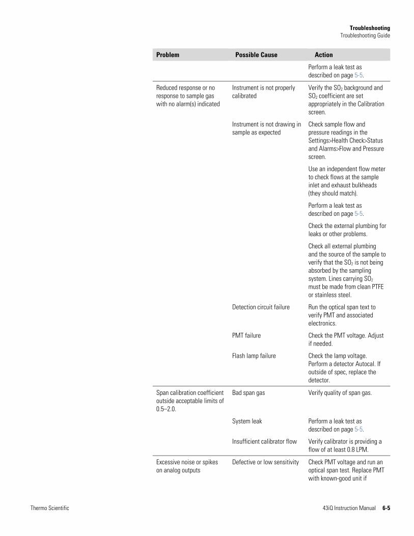
Troubleshooting Troubleshooting Guide
Thermo Scientific 43iQ Instruction Manual 6-5
Problem Possible Cause Action
Perform a leak test as described on page 5-5.
Reduced response or no response to sample gas with no alarm(s) indicated
Instrument is not properly calibrated
Verify the SO2 background and SO2 coefficient are set appropriately in the Calibration screen.
Instrument is not drawing in sample as expected
Check sample flow and pressure readings in the Settings>Health Check>Status and Alarms>Flow and Pressure screen.
Use an independent flow meter to check flows at the sample inlet and exhaust bulkheads (they should match).
Perform a leak test as described on page 5-5.
Check the external plumbing for leaks or other problems.
Check all external plumbing and the source of the sample to verify that the SO2 is not being absorbed by the sampling system. Lines carrying SO2 must be made from clean PTFE or stainless steel.
Detection circuit failure Run the optical span text to verify PMT and associated electronics.
PMT failure Check the PMT voltage. Adjust if needed.
Flash lamp failure Check the lamp voltage. Perform a detector Autocal. If outside of spec, replace the detector.
Span calibration coefficient outside acceptable limits of 0.5–2.0.
Bad span gas Verify quality of span gas.
System leak Perform a leak test as described on page 5-5.
Insufficient calibrator flow Verify calibrator is providing a flow of at least 0.8 LPM.
Excessive noise or spikes on analog outputs
Defective or low sensitivity Check PMT voltage and run an optical span test. Replace PMT with known-good unit if

Troubleshooting Troubleshooting Guide
6-6 43iQ Instruction Manual Thermo Scientific
Problem Possible Cause Action
possible.
Noise pick-up by recorder or data logger
Check analog cable shielding and replace.
Try to localize source of noise by comparing analog signal to data collected through RS-232 or Ethernet.
Poor linearity Problem with calibrator Verify accuracy of the calibration system with an independent flow meter.
Hydrocarbon kicker Replace kicker if older than 3 years.
Leak in sample probe line Check for variable dilution.
Excessive response time Averaging time is not set correctly
Check the “Averaging Time” in the Settings>Measurement Settings screen.
Instrument is not drawing in sample at the expected flow rate
Check sample flow and pressure readings in the Settings>Health Check>Status and Alarms>Flow and Pressure screen.
Use an independent flow meter to check flows at the sample inlet and exhaust bulkheads (they should match).
Perform a leak test as described on page 5-5.
SO2 is being absorbed and released by dirt in tubing or filters of the calibration system or contamination inside the instrument
Replace any lines made of vinyl or plastics with fresh PTFE or stainless steel.
Replace PTFE filter membranes that look dirty.
Remove any filters that are not PTFE membranes.
Contaminated bench Contact technical support for additional information and options.
Analog signal doesn’t match expected value
Software has not been configured
Verify that the selected analog output has been properly configured to match the data system.
Analog output goes above By default, a 5% over and

Troubleshooting Troubleshooting Guide
Thermo Scientific 43iQ Instruction Manual 6-7
Problem Possible Cause Action full-scale value or below zero
under range on the analog outputs is provided. If this is not desirable due to system restrictions, it may be turned off in the Settings>Communications>Analog I/O screen.
Recorder is drawing down output
Verify that the recorder or data logger input impedance meets minimum requirements.
Flow meter fluctuations Dirty pump diaphragm Clean or replace pump diaphragm.
Capillary blocked Clean or replace capillary.
Clogged PTFE line Inspect all sample lines.
Alarm – Chamber Temperature
Heater failed Replace heaters as needed.
Defective PCB Replace PCB.
Alarm – Perm Gas Temp Incorrect Perm oven set temperature or alarm setting
Check that the alarm settings match the set temperature.
Perm oven heater thermistor or gas thermistor error
Replace thermistor.
Perm oven failure Replace the Perm oven.
Alarm – Pressure High pressure indication Check plumbing for leaks.
Check the pump for a tear in the diaphragm. Replace if needed.
Check that the capillary is properly installed and o-rings are in good shape.
Alarm – Flow Flow low Check sample capillary for blockage. Replace as necessary.
If using sample particulate filter, make sure it is not blocked. Disconnect sample particulate filter from the sample bulkhead. If flow increases, replace the filter. Perform a leak test as decribed on page 5-5.
Flow high When delivering zero air or gas to the instrument, use an
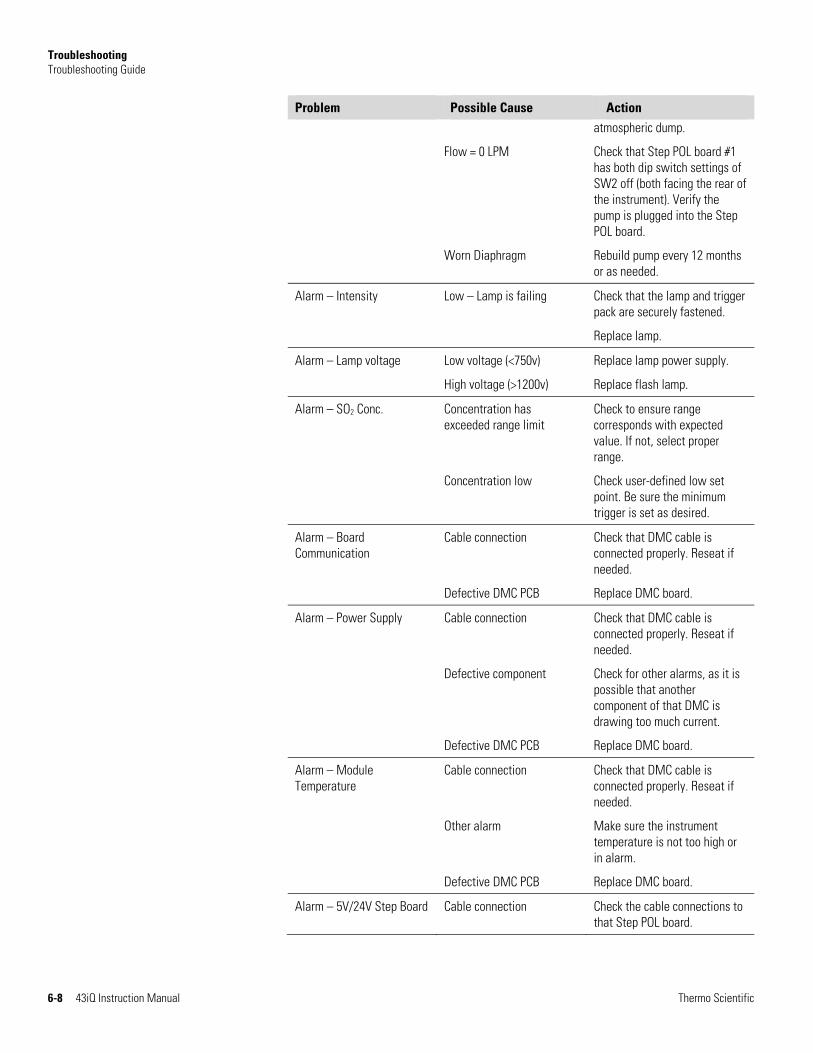
Troubleshooting Troubleshooting Guide
6-8 43iQ Instruction Manual Thermo Scientific
Problem Possible Cause Action atmospheric dump.
Flow = 0 LPM Check that Step POL board #1 has both dip switch settings of SW2 off (both facing the rear of the instrument). Verify the pump is plugged into the Step POL board.
Worn Diaphragm Rebuild pump every 12 months or as needed.
Alarm – Intensity Low – Lamp is failing Check that the lamp and trigger pack are securely fastened.
Replace lamp.
Alarm – Lamp voltage Low voltage (<750v) Replace lamp power supply.
High voltage (>1200v) Replace flash lamp.
Alarm – SO2 Conc. Concentration has exceeded range limit
Check to ensure range corresponds with expected value. If not, select proper range.
Concentration low Check user-defined low set point. Be sure the minimum trigger is set as desired.
Alarm – Board Communication
Cable connection Check that DMC cable is connected properly. Reseat if needed.
Defective DMC PCB Replace DMC board.
Alarm – Power Supply Cable connection Check that DMC cable is connected properly. Reseat if needed.
Defective component Check for other alarms, as it is possible that another component of that DMC is drawing too much current.
Defective DMC PCB Replace DMC board.
Alarm – Module Temperature
Cable connection Check that DMC cable is connected properly. Reseat if needed.
Other alarm Make sure the instrument temperature is not too high or in alarm.
Defective DMC PCB Replace DMC board.
Alarm – 5V/24V Step Board Cable connection Check the cable connections to that Step POL board.

Troubleshooting Troubleshooting Guide
Thermo Scientific 43iQ Instruction Manual 6-9
Problem Possible Cause Action
Alarm – Instrument Temperature
Fan failure Replace fan if not operating properly.
Dirty fan filter Clean or replace filter.
Overheating PCB Locate defective PCB reporting the error and replace if needed.
Alarm – Analog I/O Defective PCB Replace Analog board.
Alarm – Digital I/O Defective PCB Replace Digital board.
Alarm – Auto Bkg Cal/Check
Incorrect high alarm limit Verify the high limit is correct via Settings>Status and Alarms>Concentrations screen.
Instrument background calibration failed
Recalibrate the instrument.
Alarm – Auto Span Cal/Check
Incorrect high alarm limit Verify the high limit is correct via Settings>Status and Alarms>Concentrations screen.
Instrument span calibration failed
Recalibrate the instrument.

Thermo Scientific 43iQ Instruction Manual 7-1
Chapter 7
Servicing
This chapter describes the periodic servicing procedures that should be performed on the instrument to ensure proper operation and explains how to replace the 43iQ subassemblies.
Read the safety precautions before beginning any procedures in this chapter.
The service procedures in this manual are restricted to qualified service representatives. ▲
If the equipment is operated in a manner not specified by the manufacturer, the protection provided by the equipment may be impaired. ▲
CAUTION If the LCD panel breaks, do not let the liquid crystal contact your skin or clothes. If the liquid crystal contacts your skin or clothes, wash immediately using soap and water. ▲
Do not remove the LCD panel or frame from the LCD module. ▲
The LCD polarizing plate is very fragile, handle it carefully. ▲
Do not wipe the LCD polarizing plate with a dry cloth, as it may easily scratch the plate. ▲
Do not use alcohol, acetone, MEK or other Ketone based or aromatic solvents to clean the LCD module, but rather use a soft cloth moistened with a naphtha cleaning solvent. ▲
Do not place the LCD module near organic solvents or corrosive gases. ▲
Do not shake or jolt the LCD module. ▲
Safety Precautions
Icon Here
Icon Here
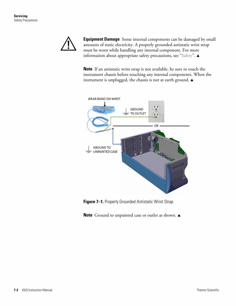
Servicing Safety Precautions
7-2 43iQ Instruction Manual Thermo Scientific
Equipment Damage Some internal components can be damaged by small amounts of static electricity. A properly grounded antistatic wrist strap must be worn while handling any internal component. For more information about appropriate safety precautions, see “Safety”. ▲
Note If an antistatic wrist strap is not available, be sure to touch the instrument chassis before touching any internal components. When the instrument is unplugged, the chassis is not at earth ground. ▲
Figure 7–1. Properly Grounded Antistatic Wrist Strap
Note Ground to unpainted case or outlet as shown. ▲
Servicing Firmware Updates
Thermo Scientific 43iQ Instruction Manual 7-3
New versions of the instrument software are periodically made available over Ethernet, USB flash drive, or company website at:
www.thermofisher.com
For more information on installing new firmware, see “Installing New Firmware” in the iQ Series Communications manual.
For a complete list of spare parts, visit the company website at:
www.thermofisher.com/43iQ
Refer to Figure 7–2 and Figure 7–3 to identify the component location.
FirmwareUpdates
ReplacementParts List

Servicing Replacement Parts List
7-4 43iQ Instruction Manual Thermo Scientific
Figure 7–2. 43iQ Component Layout Top View
Figure 7–3. 43iQ Component Layout Side View

Servicing Fuse Replacement
Thermo Scientific 43iQ Instruction Manual 7-5
Use the following procedure to replace the fuses.
1. Turn instrument OFF and unplug the power cord.
2. Remove fuse drawer, located on the AC power connector.
3. If either fuse is blown, replace both fuses.
4. Insert fuse drawer and reconnect power cord.
Figure 7–4. Replacing the Fuses
Fuse Replacement
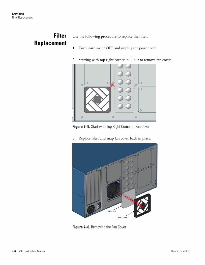
Servicing Filter Replacement
7-6 43iQ Instruction Manual Thermo Scientific
Use the following procedure to replace the filter.
1. Turn instrument OFF and unplug the power cord.
2. Starting with top right corner, pull out to remove fan cover.
Figure 7–5. Start with Top Right Corner of Fan Cover
3. Replace filter and snap fan cover back in place.
Figure 7–6. Removing the Fan Cover
Filter Replacement
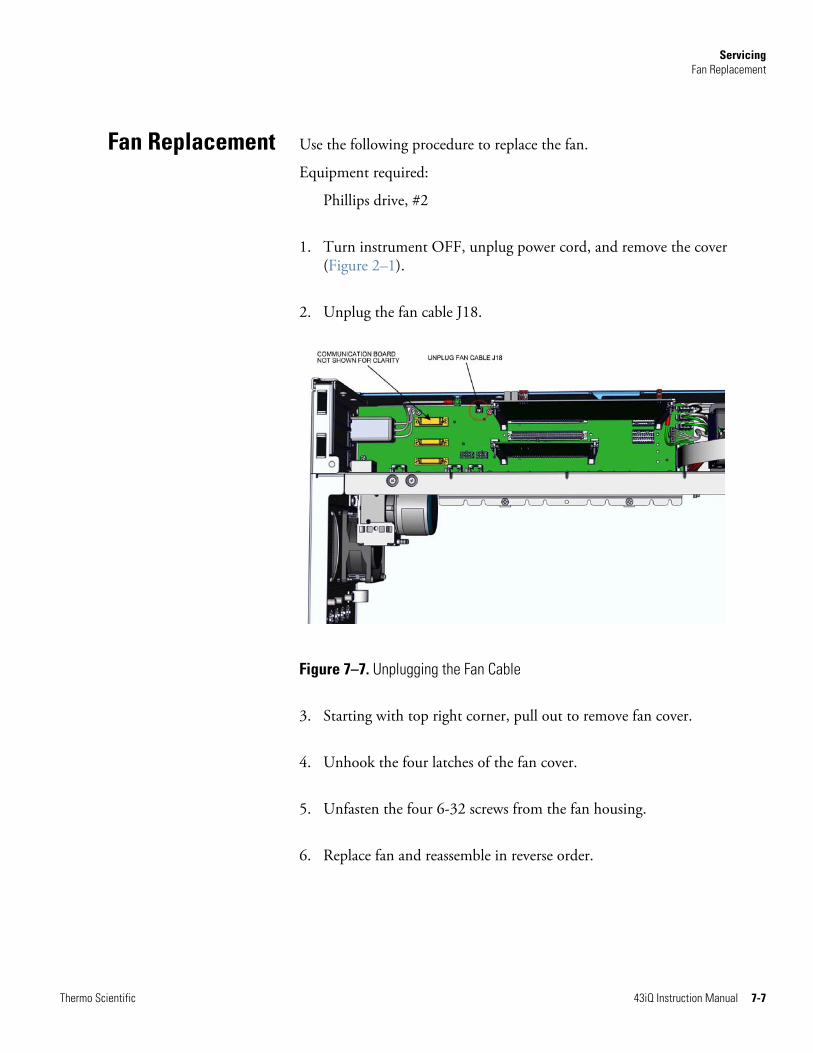
Servicing Fan Replacement
Thermo Scientific 43iQ Instruction Manual 7-7
Use the following procedure to replace the fan.
Equipment required:
Phillips drive, #2
1. Turn instrument OFF, unplug power cord, and remove the cover (Figure 2–1).
2. Unplug the fan cable J18.
Figure 7–7. Unplugging the Fan Cable
3. Starting with top right corner, pull out to remove fan cover.
4. Unhook the four latches of the fan cover.
5. Unfasten the four 6-32 screws from the fan housing.
6. Replace fan and reassemble in reverse order.
Fan Replacement
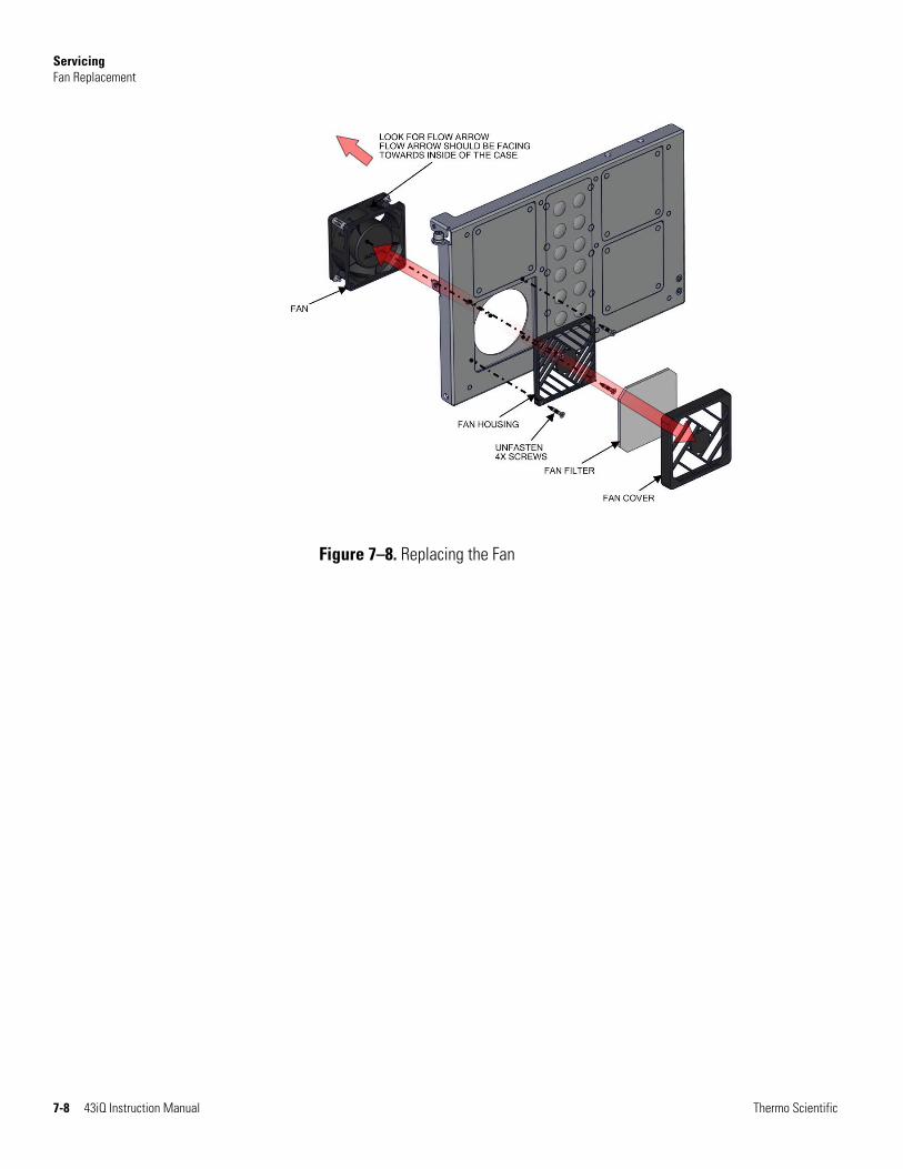
Servicing Fan Replacement
7-8 43iQ Instruction Manual Thermo Scientific
Figure 7–8. Replacing the Fan

Servicing Measurement Side Removal and Replacing
Thermo Scientific 43iQ Instruction Manual 7-9
Use the following procedure to remove and replace the measurement side if necessary.
Equipment required:
Phillips drive, #2
1. Turn instrument OFF, unplug power cord, and remove the cover (Figure 2–1).
2. Unplug the fan cable J18 (Figure 7–9).
Figure 7–9. Unplugging the Fan Cable
3. Unplug DMC cable (Figure 7–10).
MeasurementSide Removal
and Replacing

Servicing Measurement Side Removal and Replacing
7-10 43iQ Instruction Manual Thermo Scientific
Figure 7–10. Unplugging the DMC Cable
4. Gripping from the top corners of the front panel and pull outwards.
5. Remove three 8-32 flat head screws (Figure 7–11).
Figure 7–11. Unfasten Hardware Front for Measurement Side Removal
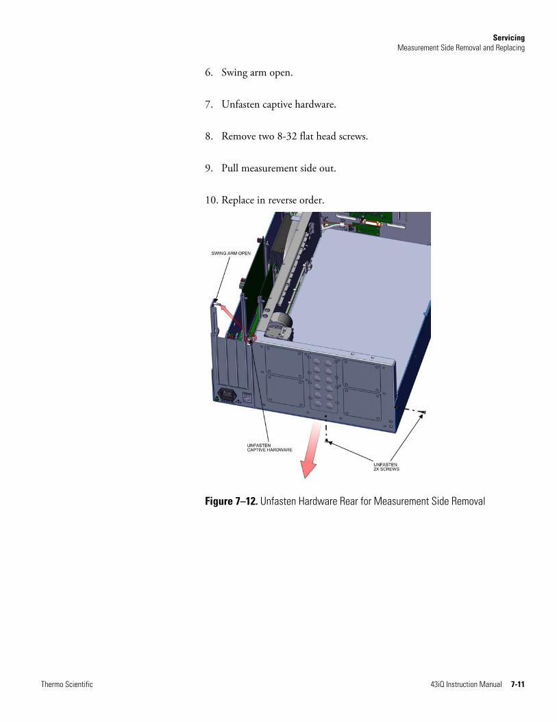
Servicing Measurement Side Removal and Replacing
Thermo Scientific 43iQ Instruction Manual 7-11
6. Swing arm open.
7. Unfasten captive hardware.
8. Remove two 8-32 flat head screws.
9. Pull measurement side out.
10. Replace in reverse order.
Figure 7–12. Unfasten Hardware Rear for Measurement Side Removal

Servicing LCD Module Replacement
7-12 43iQ Instruction Manual Thermo Scientific
Use the following procedure to replace the LCD module.
Equipment required:
Wrench, 1/4
1. Turn instrument OFF and unplug the power cord.
2. Gripping from the top corners of the front panel and pull outwards.
3. Unfasten four nuts (Figure 7–13).
Figure 7–13. Replacing the LCD Module
4. Remove cover.
5. Unplug LCD cables from backside of board.
6. Pull board off the standoffs.
LCD ModuleReplacement

Servicing LCD Module Replacement
Thermo Scientific 43iQ Instruction Manual 7-13
Figure 7–14. Remove Electrical Cables from LCD
7. Replace LCD module and reassemble in reverse order.

Servicing I/O Replacement
7-14 43iQ Instruction Manual Thermo Scientific
Use the following procedure to replace the I/O boards.
1. Turn instrument OFF, unplug power cord, and remove the cover (Figure 2–1).
2. Swing arm open.
Figure 7–15. I/O Replacement, Arm
3. Pull board upwards.
Figure 7–16. I/O Replacement, Remove Board
I/O Replacement

Servicing I/O Replacement
Thermo Scientific 43iQ Instruction Manual 7-15
4. During install, make sure to align cutout circular to keyway.
5. Insert board downwards.
Figure 7–17. I/O Replacement, Install
6. Close arm. Make sure expansion bracket aligns to the inside of the rectangular cutouts.
Figure 7–18. I/O Replacement, Close Arm Alignment

Servicing Peripherals Support Board and System Controller Board Replacement
7-16 43iQ Instruction Manual Thermo Scientific
Use the following procedure to replace the peripherals support board or system controller board.
1. Turn instrument OFF, unplug power cord, and remove the cover (Figure 2–1).
2. Pull tab out (two per board).
3. Pull board out.
Figure 7–19. Replacing the Peripherals Support Board
4. Replace board and reassemble in reverse order.
PeripheralsSupport Board
and System Controller Board
Replacement

Servicing DMC Pressure and Flow Board
Thermo Scientific 43iQ Instruction Manual 7-17
Use the following to replace the DMC pressure and flow board.
Equipment required:
Hex drive, 7/16
1. Turn instrument OFF, unplug power cord, and remove the cover (Figure 2–1).
2. Unplug cables from the pressure and flow board.
Figure 7–20. Flow Pressure Board, Disconnect DMC Cable
3. Disconnect plumbing.
4. Using 7/16 hex drive, unfasten four #6-32 socket cap head screws.
DMC Pressureand Flow Board

Servicing DMC Pressure and Flow Board
7-18 43iQ Instruction Manual Thermo Scientific
Figure 7–21. Flow Pressure Board, Screws
5. Replace board and reassemble in reverse order.

Servicing Pump Replacement
Thermo Scientific 43iQ Instruction Manual 7-19
Use the following procedure to replace the pump.
Equipment required:
Phillips drive, #1 and #2
1. Turn instrument OFF, unplug power cord, and remove the cover (Figure 2–1).
2. Unplug pump cable from step pol board J7.
3. Twist opposite direction to unlock tube clamps.
Note Push in tube clamp to lock. ▲
4. Disconnect tubing from pump.
5. Unfasten two captive hardware.
6. Slide pump left until keyway meets opening.
Pump Replacement

Servicing Pump Replacement
7-20 43iQ Instruction Manual Thermo Scientific
Figure 7–22. Remove Pump, Disconnect and Unfasten
7. Pull pump outwards.
Note When installing pump, make sure the pump keyway opening goes over the keyway. ▲
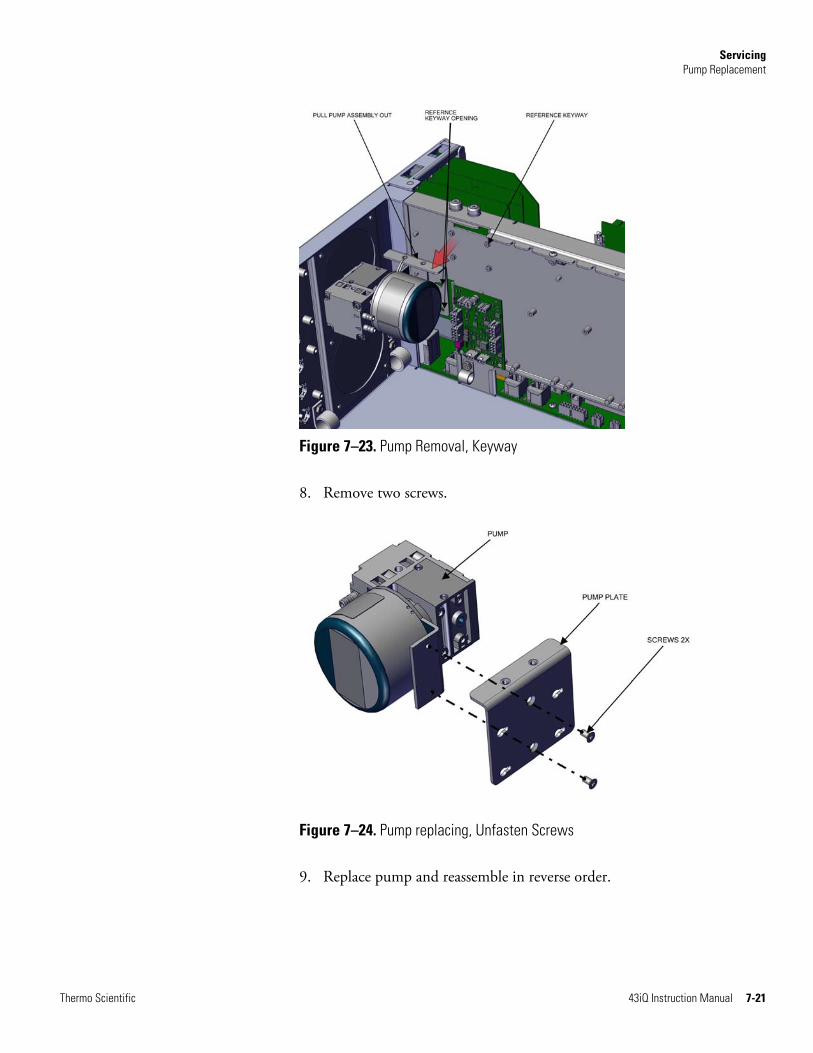
Servicing Pump Replacement
Thermo Scientific 43iQ Instruction Manual 7-21
Figure 7–23. Pump Removal, Keyway
8. Remove two screws.
Figure 7–24. Pump replacing, Unfasten Screws
9. Replace pump and reassemble in reverse order.

Servicing Capillary Cleaning and/or Replacement
7-22 43iQ Instruction Manual Thermo Scientific
Use the following procedure to clean or replace the capillary.
Equipment required:
Phillips drive, #2
Hex drive, 7/64
1. Turn instrument OFF, unplug power cord, and remove the cover (Figure 2–1).
2. Disconnect the plumbing.
3. Unfasten captive hardware.
Figure 7–25. Remove Capillary, Disconnect and Unfasten
4. Slide capillary plate upwards clearing the partition panel keyway.
CapillaryCleaning and/or
Replacement

Servicing Capillary Cleaning and/or Replacement
Thermo Scientific 43iQ Instruction Manual 7-23
Figure 7–26. Capillary Plate, Keyway
5. Using 7/64 hex drive, remove four #6-32 socket cap head screws.
6. Pull apart the capillary blocks.
Figure 7–27. Capillary and O-Ring Replace
Servicing Capillary O-Ring Replacement
7-24 43iQ Instruction Manual Thermo Scientific
7. Replace capillary and reassemble in reverse order.
Note Fitting arrangements, number of capillaries and capillary sizes will vary per instrument configuration. ▲
Use the following procedure to replace the capillary o-rings.
Equipment required:
O-ring pick tool
1. Using a metal o-ring pick tool, remove the o-ring.
Note Be careful in not damaging the o-ring walls during this process. Refer to Figure 7–27. ▲
Use the following procedure to replace the power supply.
Equipment required:
Phillips drive, #2
1. Turn instrument OFF, unplug power cord, and remove the cover (Figure 2–1).
2. Unplug all electrical shown J9, J10, J24, J25, J26, and ground.
3. Unfasten captive hardware.
4. Slide power supply left, clearing three case floor plate keyways.
Capillary O-Ring Replacement
Power SupplyReplacement

Servicing Power Supply Replacement
Thermo Scientific 43iQ Instruction Manual 7-25
Figure 7–28. Removing Power Supply
5. Pull power supply up.
6. Replace power supply and reassemble in reverse order.
Figure 7–29. Replacing Power Supply
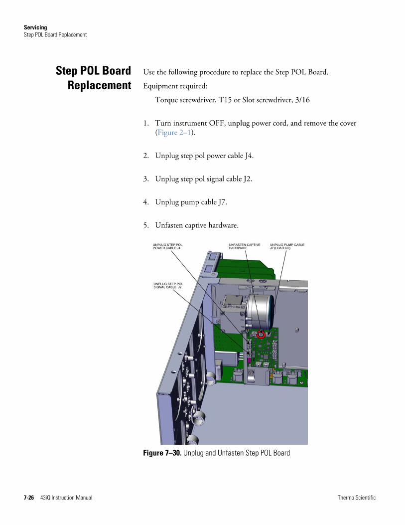
Servicing Step POL Board Replacement
7-26 43iQ Instruction Manual Thermo Scientific
Use the following procedure to replace the Step POL Board.
Equipment required:
Torque screwdriver, T15 or Slot screwdriver, 3/16
1. Turn instrument OFF, unplug power cord, and remove the cover (Figure 2–1).
2. Unplug step pol power cable J4.
3. Unplug step pol signal cable J2.
4. Unplug pump cable J7.
5. Unfasten captive hardware.
Figure 7–30. Unplug and Unfasten Step POL Board
Step POL Board Replacement

Servicing Step POL Board Replacement
Thermo Scientific 43iQ Instruction Manual 7-27
Figure 7–31. Clear Partition Keyway Step POL Board
6. Slide step board 1 upwards clearing the partition panel keyway.
7. If replacing step board 1, make sure switch 1 and 2 are pointed away from ON (Figure 7–32). If replacing optional step board 2, make sure switch 1 is pointed towards ON and switch 2 is pointed away from ON (Figure 7–33).
8. Replace step pol board and reassemble in reverse order.

Servicing Step POL Board Replacement
7-28 43iQ Instruction Manual Thermo Scientific
Figure 7–32. Step POL Board 1 Switch Settings
Figure 7–33. Optional Step POL Board 2 Switch Settings

Servicing DMC Optical Bench Removal
Thermo Scientific 43iQ Instruction Manual 7-29
Use the following to remove the DMC optical bench from the instrument.
● Optical Bench Assembly Removal
● PMT Replacement
● Flasher Pack Replacement
● Flasher Pack Lamp Replacement
● Photo Lamp Detector Board Replacement
● Kicker Assembly Replacement
Use the following procedure to remove the optical bench assembly.
Equipment required:
Phillips drive, #2
1. Turn instrument OFF, unplug power cord, and remove the cover (Figure 2–1).
2. Unplug two DMC cables.
3. Disconnect all plumbing.
4. Unfasten six captive hardware.
DMC OpticalBench Removal
Optical BenchAssembly Removal
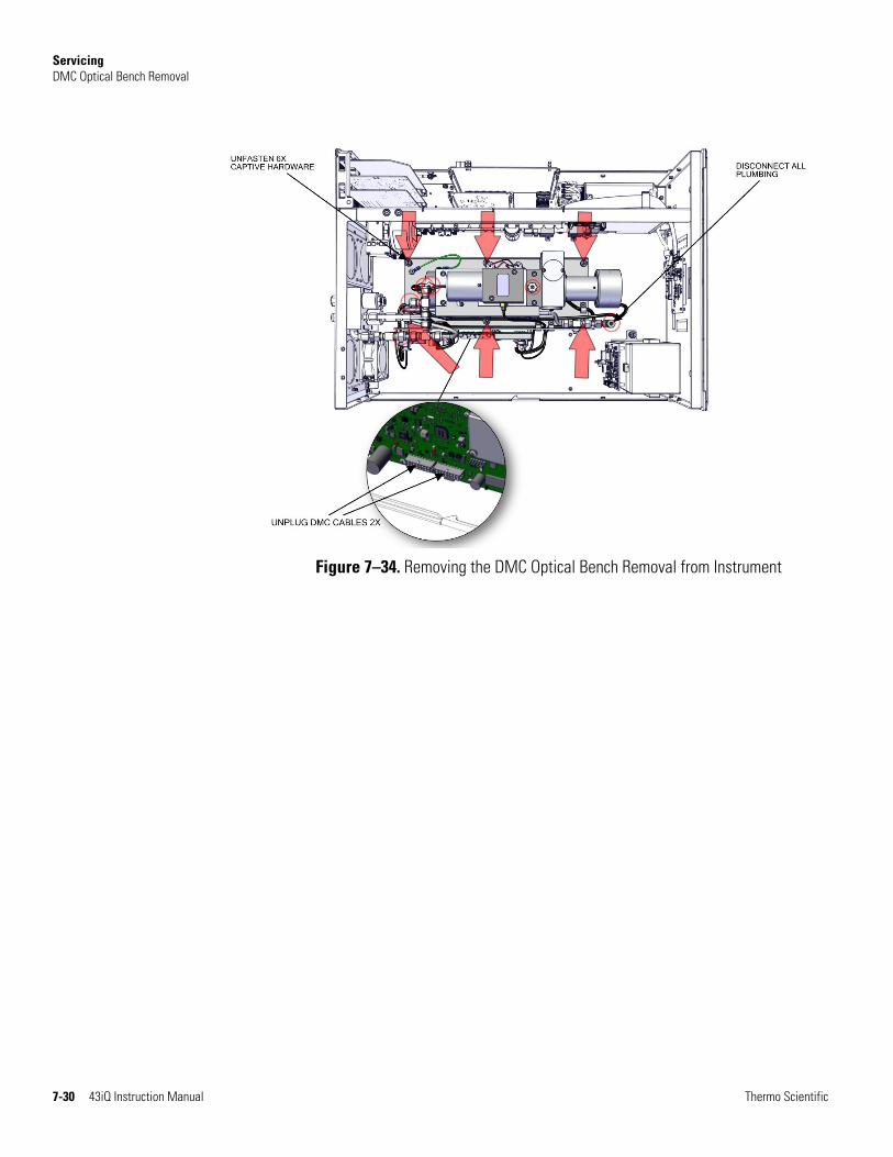
Servicing DMC Optical Bench Removal
7-30 43iQ Instruction Manual Thermo Scientific
Figure 7–34. Removing the DMC Optical Bench Removal from Instrument

Servicing DMC Optical Bench Removal
Thermo Scientific 43iQ Instruction Manual 7-31
Use the following to remove the optical bench assembly.
Equipment required:
Hex nut drive, 3/8 and 5/32 and hex drive, 5/32
1. Unplug all electrical as shown (Figure 7–35).
Figure 7–35. Removing the Optical Bench Assembly
2. Using 3/8 hex nut drive, unfasten nut.
3. Using 5/32 hex drive, unfasten two #10-32 socket cap head screws.
4. Pull optical bench assembly upwards (Figure 7–36).
Optical BenchAssembly Removal
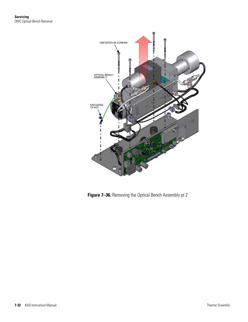
Servicing DMC Optical Bench Removal
7-32 43iQ Instruction Manual Thermo Scientific
Figure 7–36. Removing the Optical Bench Assembly pt 2

Servicing DMC Optical Bench Removal
Thermo Scientific 43iQ Instruction Manual 7-33
Use the following to replace the photomultiplier tube (PMT).
Equipment required:
Hex drive, 5/32
Phillips drive, #1 and #2
Lint-free gloves
1. Turn the instrument OFF, unplug the power cord, and remove the cover.
2. Unplug all electrical as shown (Figure 7–37).
3. Using 5/32 hex drive, unfasten two #10-32 socket cap head screws.
4. Pull photomultiplier housing upwards.
Figure 7–37. Removing the PMT Assembly
PhotomultiplierTube (PMT)
Replacement
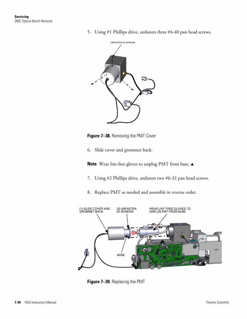
Servicing DMC Optical Bench Removal
7-34 43iQ Instruction Manual Thermo Scientific
5. Using #1 Phillips drive, unfasten three #4-40 pan head screws.
Figure 7–38. Removing the PMT Cover
6. Slide cover and grommet back.
Note Wear lint-free gloves to unplug PMT from base. ▲
7. Using #2 Phillips drive, unfasten two #6-32 pan head screws.
8. Replace PMT as needed and assemble in reverse order.
Figure 7–39. Replacing the PMT

Servicing DMC Optical Bench Removal
Thermo Scientific 43iQ Instruction Manual 7-35
Use the following procedure to replace the flasher pack.
Equipment required:
Hex drive, 1/16
1. Unplug flash trig from board.
2. Loosen 6-32 set screw until the flasher pack/lamp can be eased out of housing.
Figure 7–40. Removing and Replacing the Flasher Pack
Flasher PackReplacement

Servicing DMC Optical Bench Removal
7-36 43iQ Instruction Manual Thermo Scientific
Use the following procedure to replace and flasher pack lamp.
Equipment required:
Lint-free gloves
1. Wearing lint-free gloves unplug the lamp from the flasher pack.
Figure 7–41. Replacing the Flasher Pack Lamp
2. Replace flasher pack lamp and assemble in reverse order.
Flasher Pack Lamp Replacement

Servicing DMC Optical Bench Removal
Thermo Scientific 43iQ Instruction Manual 7-37
Use the following procedure to remove and replace the photo lamp detector board.
Equipment required:
Phillips drive, #1 and #2
1. Unplug cable.
2. Using #2 Phillips drive, unfasten three #6-32 pan head screws.
Figure 7–42. Replacing the Photo Lamp Detector Board pt 1
3. Pull detector cover outwards.
4. Using #1 Phillips drive, unfasten four #4-40 pan head screws.
5. Pull photo lamp detector board outwards.
6. Replace lamp detector board and assemble in reverse order.
Photo Lamp Detector Board
Replacement
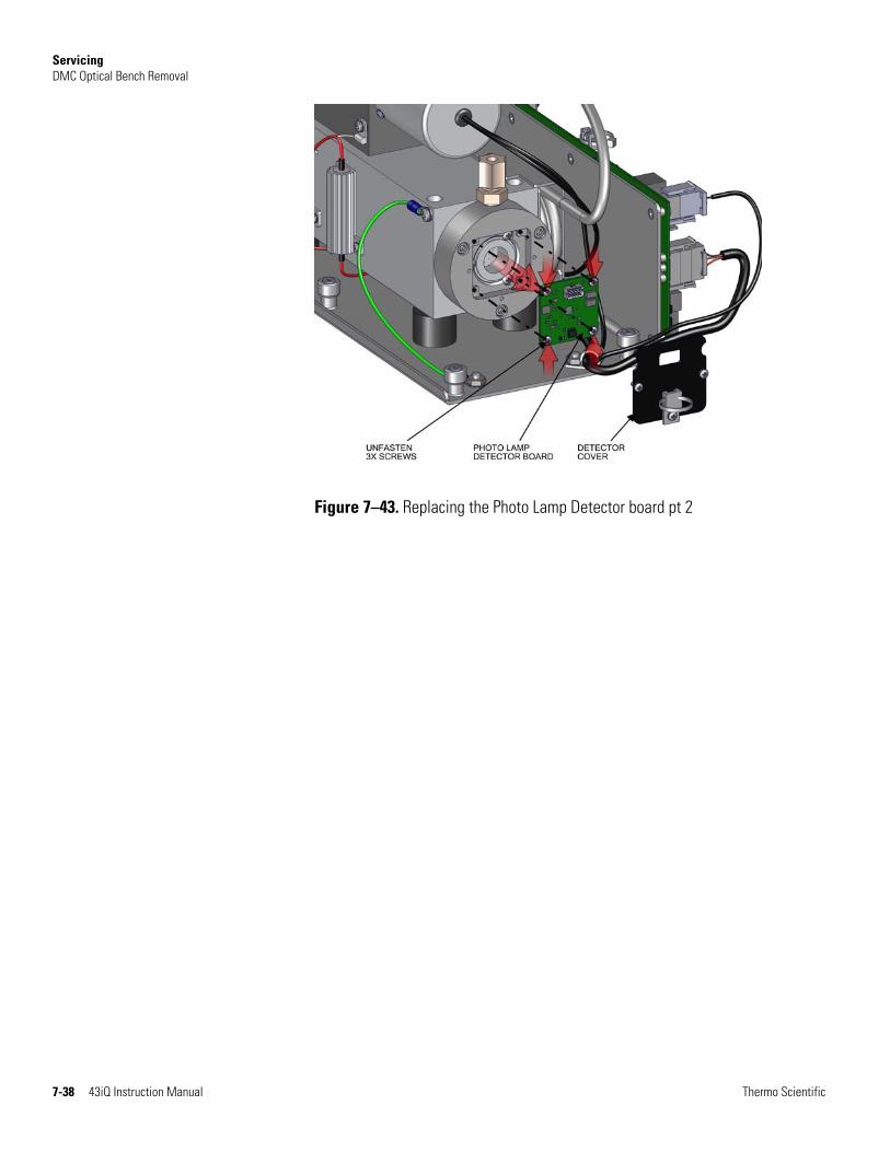
Servicing DMC Optical Bench Removal
7-38 43iQ Instruction Manual Thermo Scientific
Figure 7–43. Replacing the Photo Lamp Detector board pt 2
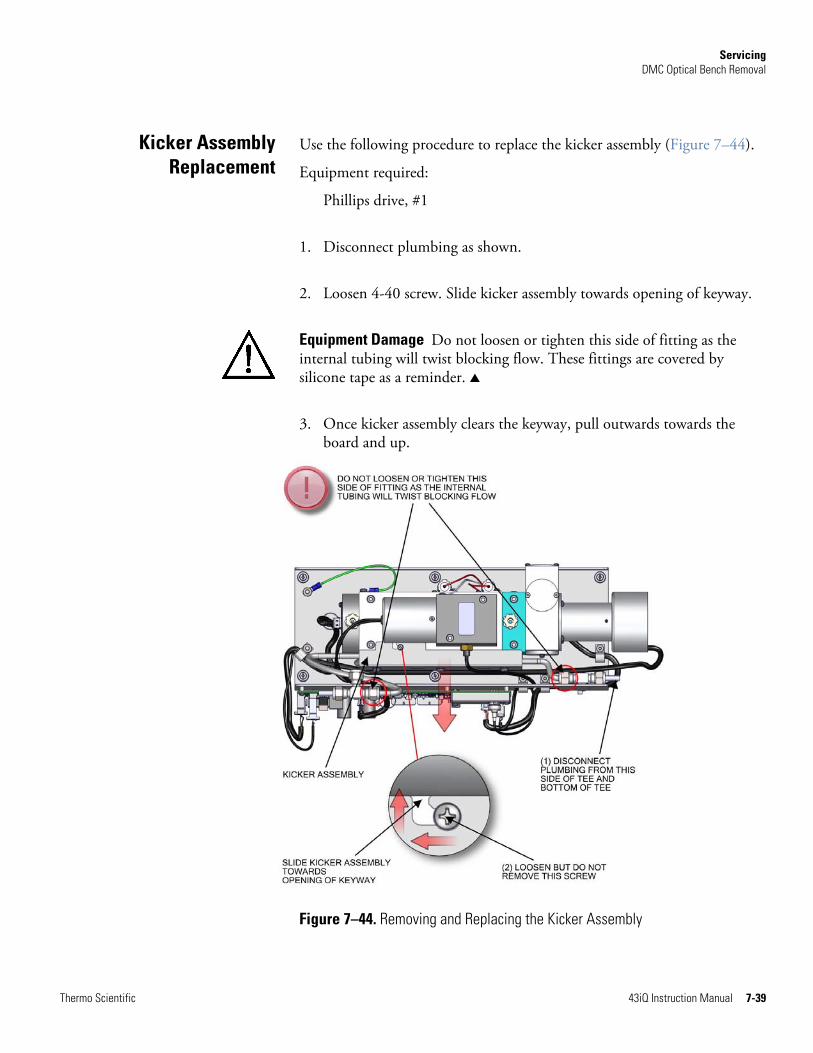
Servicing DMC Optical Bench Removal
Thermo Scientific 43iQ Instruction Manual 7-39
Use the following procedure to replace the kicker assembly (Figure 7–44).
Equipment required:
Phillips drive, #1
1. Disconnect plumbing as shown.
2. Loosen 4-40 screw. Slide kicker assembly towards opening of keyway.
Equipment Damage Do not loosen or tighten this side of fitting as the internal tubing will twist blocking flow. These fittings are covered by silicone tape as a reminder. ▲
3. Once kicker assembly clears the keyway, pull outwards towards the board and up.
Figure 7–44. Removing and Replacing the Kicker Assembly
Kicker AssemblyReplacement
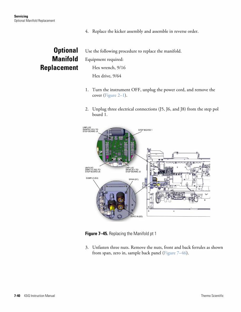
Servicing Optional Manifold Replacement
7-40 43iQ Instruction Manual Thermo Scientific
4. Replace the kicker assembly and assemble in reverse order.
Use the following procedure to replace the manifold.
Equipment required:
Hex wrench, 9/16
Hex drive, 9/64
1. Turn the instrument OFF, unplug the power cord, and remove the cover (Figure 2–1).
2. Unplug three electrical connections (J5, J6, and J8) from the step pol board 1.
Figure 7–45. Replacing the Manifold pt 1
3. Unfasten three nuts. Remove the nuts, front and back ferrules as shown from span, zero in, sample back panel (Figure 7–46).
OptionalManifold
Replacement
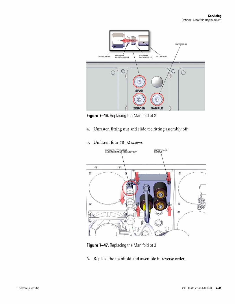
Servicing Optional Manifold Replacement
Thermo Scientific 43iQ Instruction Manual 7-41
Figure 7–46. Replacing the Manifold pt 2
4. Unfasten fitting nut and slide tee fitting assembly off.
5. Unfasten four #8-32 screws.
Figure 7–47. Replacing the Manifold pt 3
6. Replace the manifold and assemble in reverse order.
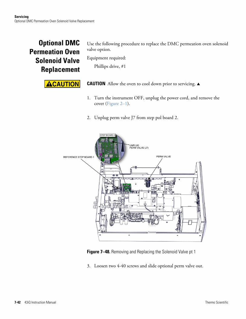
Servicing Optional DMC Permeation Oven Solenoid Valve Replacement
7-42 43iQ Instruction Manual Thermo Scientific
Use the following procedure to replace the DMC permeation oven solenoid valve option.
Equipment required:
Phillips drive, #1
CAUTION Allow the oven to cool down prior to servicing. ▲
1. Turn the instrument OFF, unplug the power cord, and remove the cover (Figure 2–1).
2. Unplug perm valve J7 from step pol board 2.
Figure 7–48. Removing and Replacing the Solenoid Valve pt 1
3. Loosen two 4-40 screws and slide optional perm valve out.
Optional DMCPermeation Oven
Solenoid ValveReplacement

Servicing Optional DMC Permeation Oven Solenoid Valve Replacement
Thermo Scientific 43iQ Instruction Manual 7-43
Equipment Damage Do not disconnect the plumbing from the valve end. Disconnect from the attaching end only. This will prevent damaging and leaks from the valve end. ▲
Figure 7–49. Removing and Replacing the Solenoid Valve pt 2
4. Replace the permeation oven solenoid valve and assemble in reverse order.
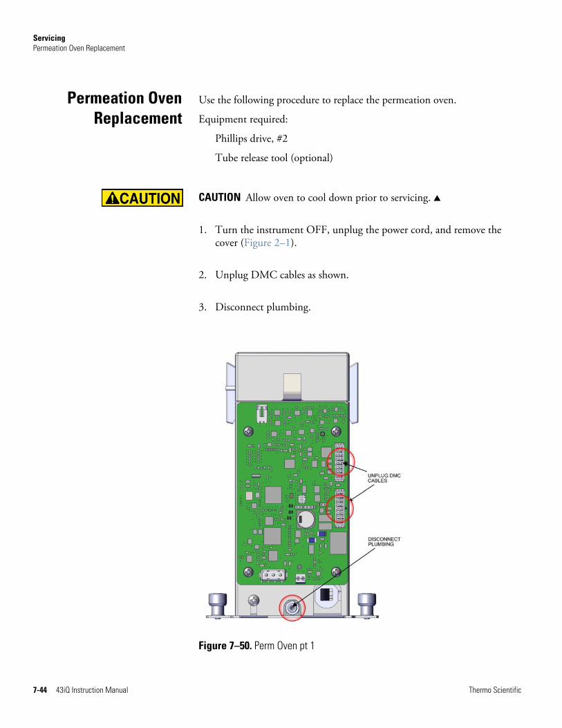
Servicing Permeation Oven Replacement
7-44 43iQ Instruction Manual Thermo Scientific
Use the following procedure to replace the permeation oven.
Equipment required:
Phillips drive, #2
Tube release tool (optional)
CAUTION Allow oven to cool down prior to servicing. ▲
1. Turn the instrument OFF, unplug the power cord, and remove the cover (Figure 2–1).
2. Unplug DMC cables as shown.
3. Disconnect plumbing.
Figure 7–50. Perm Oven pt 1
Permeation OvenReplacement
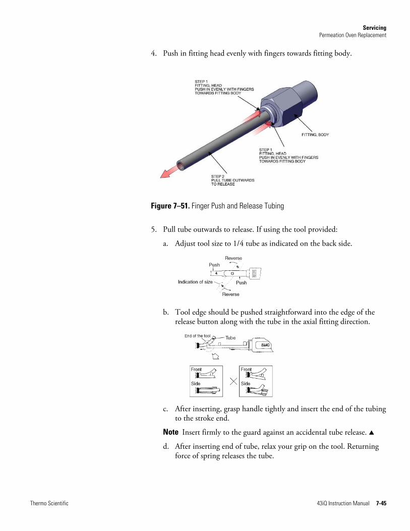
Servicing Permeation Oven Replacement
Thermo Scientific 43iQ Instruction Manual 7-45
4. Push in fitting head evenly with fingers towards fitting body.
Figure 7–51. Finger Push and Release Tubing
5. Pull tube outwards to release. If using the tool provided:
a. Adjust tool size to 1/4 tube as indicated on the back side.
b. Tool edge should be pushed straightforward into the edge of the
release button along with the tube in the axial fitting direction.
c. After inserting, grasp handle tightly and insert the end of the tubing
to the stroke end.
Note Insert firmly to the guard against an accidental tube release. ▲
d. After inserting end of tube, relax your grip on the tool. Returning force of spring releases the tube.

Servicing Permeation Oven Replacement
7-46 43iQ Instruction Manual Thermo Scientific
Push both sides at once to release. Reverse and fix at the same position as before. Applicable tube size is indicated on the back side.
6. Disconnect plumbing from inline fitting.
Note Do not disconnect from valve end. ▲
7. Unfasten two captive hardware.
Figure 7–52. Perm Oven Replacement pt 2
8. Replace DMC permeation oven and assembly in reverse order.

Servicing Permeation Oven Board Replacement
Thermo Scientific 43iQ Instruction Manual 7-47
Use the following procedure to replace the permeation oven board.
Equipment required:
Phillips drive, #2
CAUTION Allow oven to cool down prior to servicing. ▲
1. Turn instrument OFF, unplug power cord, and remove the cover (Figure 2–1).
2. Unplug all electrical J1, J7, J8, J9 as shown.
3. Using #2 Phillips drive, unfasten four 6-32 pan head screws.
Figure 7–53. Replacing the Permeation Oven Board
4. Replace permeation board and assemble in reverse order.
Permeation OvenBoard
Replacement


Thermo Scientific 43iQ Instruction Manual 8-1
Chapter 8
System Description
The 43iQ deploys a set of modular subsystems that comprise the total instrument function. The core measurements for concentration are contained in Distributed Measurement and Control (DMC) modules. This chapter describes the function and location of the system components in the module framework, including firmware, electronics, and I/O function.
The 43iQ system components include:
● Optical Bench DMC
● Heated hydrocarbon kicker
● Optical Bench hardware with bandpass filters and mirrors
● Flash lamp trigger assembly
● Photomultiplier tube (PMT)
● Photodetector
● Optical bench DMC board
● Permeation Oven (optional)
● Common Electronics
● Power Supply
● System controller board
● Backplane board
● Front panel
● I/O (optional)
● Peripherals Support System
● Fan (on rear panel)
● Step POL board
● Sample pump
● Solenoid valve panel (optional)
● Flow Pressure DMC with flow restricting capillary
System Description Optical Bench DMC
8-2 43iQ Instruction Manual Thermo Scientific
● Firmware
The Optical Bench DMC contains the key components of the optical measurement that eventually results in SO2 concentration. In the reaction chamber pulsating light from the flash lamp excites the SO2 molecules. A condenser lens collects and focuses light from fluorescing SO2 molecules onto the PMT assembly.
The heated hydrocarbon kicker removes hydrocarbons from the gas stream while leaving the SO2 concentration unaffected. It operates on a selective permeation principle using differential pressure to force hydrocarbon molecules to pass through the tube wall. The differential pressure is created across the tube wall as sample gas passes through a capillary tube which reduces its pressure. The sample gas is then fed to the shell side of the hydrocarbon kicker. The heated kicker operates at the same temperature as the optical bench and requires no additional power.
The optics section provides the light source for the fluorescence reaction and optimizes the reaction with a system of lenses and mirrors. It includes a flash lamp, condensing lens, bandpass mirror assembly and light baffle.
The condensing lens focuses light from the flash lamp into the mirror assembly.
A set of four mirrors selectively reflects only those wavelengths used in exciting SO2 molecules. This reflective filtering causes the radiation reaching the detection chamber to be more intense and more stable throughout the lifetime of the instrument.
The circular baffle helps keep stray light from entering the detection volume.
The bandpass filter restricts the light reaching the photomultiplier tube to the SO2 fluorescence wavelengths.
Optical BenchDMC
Heated HydrocarbonKicker
Optical BenchHardware
Condensing Lens
Mirror Assembly
Light Baffle
Bandpass Filter

System Description Optical Bench DMC
Thermo Scientific 43iQ Instruction Manual 8-3
The flash lamp trigger assembly pulses the UV flash lamp at a rate of 10 times per second for improved signal-to-noise ratio and long term stability.
The lamp is operated in the pulsed mode for six major reasons:
● Long life
● High optical intensity – improved signal to noise ratio
● Small size
● Low power requirements – less than 1 watt
● Long-term stability
● Chopped signal processing – no dark current drift
The flash lamp provides the ultraviolet light source that causes the fluorescence reaction in the SO2 molecules.
The flash trigger board is located in the base of the flash lamp assembly. It receives high voltage and the trigger signal from the measurement interface board and uses a small transformer to produce a short, high-voltage pulse to fire the flash lamp.
The flash intensity assembly is located in the fluorescence chamber and continuously monitors the pulsating UV flash lamp. This photodetector is connected to a circuit that automatically compensates for fluctuations in flash lamp output.
The PMT power supply produces high voltage to operate the photomultiplier tube used in the measurement system. The output voltage is adjustable from approximately 600 to 1200 volts under software control. The PMT converts optical energy from the reaction to an electrical signal. This signal is sent to the input board which transmits it to the processor.
The optical bench DMC board accepts the current signal from the PMT and converts it to a voltage, which is scaled by a factor of approximately 1, 10, or 100 depending on the full-scale range of the SO2 channel.
Flash Lamp TriggerAssembly
Flash Lamp
Flash Trigger Board
Flash Intensity Assembly
PhotomultiplierTube
Optical Bench DMCBoard
System Description Permeation Oven (Optional)
8-4 43iQ Instruction Manual Thermo Scientific
The fluorescence chamber temperature is measured with a thermistor. The voltage across the thermistor is fed to the main processor for use in calculating and displaying the reaction chamber temperature. The voltage across the thermistor is also compared to a set-point voltage and used to control that the reaction chamber heaters to maintain a constant temperature.
The 43iQ can be configured with an optional permeation oven for generating SO2 span gas. The permeation oven is configured as a DMC module with self-contained temperature measurements and heater controls. For more information, see “Internal Permeation Span Source” as described in Chapter 9, “Optional Equipment”.
The common electronics contain the core computational and power routing hardware for the 43iQ, and is replicated throughout other iQ series products (Figure 8–1). It also contains the front panel display, the USB ports, the Ethernet port, and the optional I/O interfaces (RS-485, analog, and digital).
Figure 8–2 shows the PCBA interconnect structure for the 43iQ, including options. The modular design of the instrument is conveyed in the architecture. Brief descriptions of the specific PCBAs follow.
Bench Heater
Permeation Oven(Optional)
CommonElectronics

System Description Common Electronics
Thermo Scientific 43iQ Instruction Manual 8-5
PE
RIP
HE
RA
L'S
SU
PP
OR
T B
OA
RD
DIG
ITA
L I
/OB
OA
RD
BA
CK
PLA
NE
BO
AR
D
AN
AL
OG
I/O
BO
AR
D
CO
MM
UN
ICA
TIO
NS
BO
AR
D
"A"
"B"
A/C
INF
RO
NT
PA
NE
L
LA
NU
SB
24V
DC
48V
DC
+24
V F
an
+24V
PO
WE
R S
UPP
LY
LIN
E P
OW
ER
FIL
TER
SW
ITC
H
GN
D
SY
ST
EM
CO
NT
RO
LL
ER
BO
AR
D
A/C
FR
ON
T U
SB
PO
RT
BO
AR
D
DIS
PL
AY
LE
DS
MFC
1
TO
UC
H S
CR
EE
N L
CD
DIS
PL
AY
+48V
PO
WE
R S
UPP
LY
DM
C 1
DM
C 2
24V
POW
ER
2PO
L 1
DA
TA
POL
2, 2
4V
POL
1, 2
4VPO
WE
R
POW
ER
POL
2D
AT
A24
VPO
WE
R 1
RE
SET
FRO
NT
PA
NE
L
(Onl
y if
48V
is r
equi
red)
BO
AR
D
Bac
kpla
ne
Mea
sure
men
t Cas
e
MFC
2
MFC
3
Not
all
con
nect
ions
app
ly to
all
Mod
el iQ
inst
rum
ents
.
OU
T
A/C
OU
T
GR
OU
ND
TA
B
-
iQ S
erie
s C
omm
on P
latf
orm
Figure 8–1. Common System Interconnect Diagram
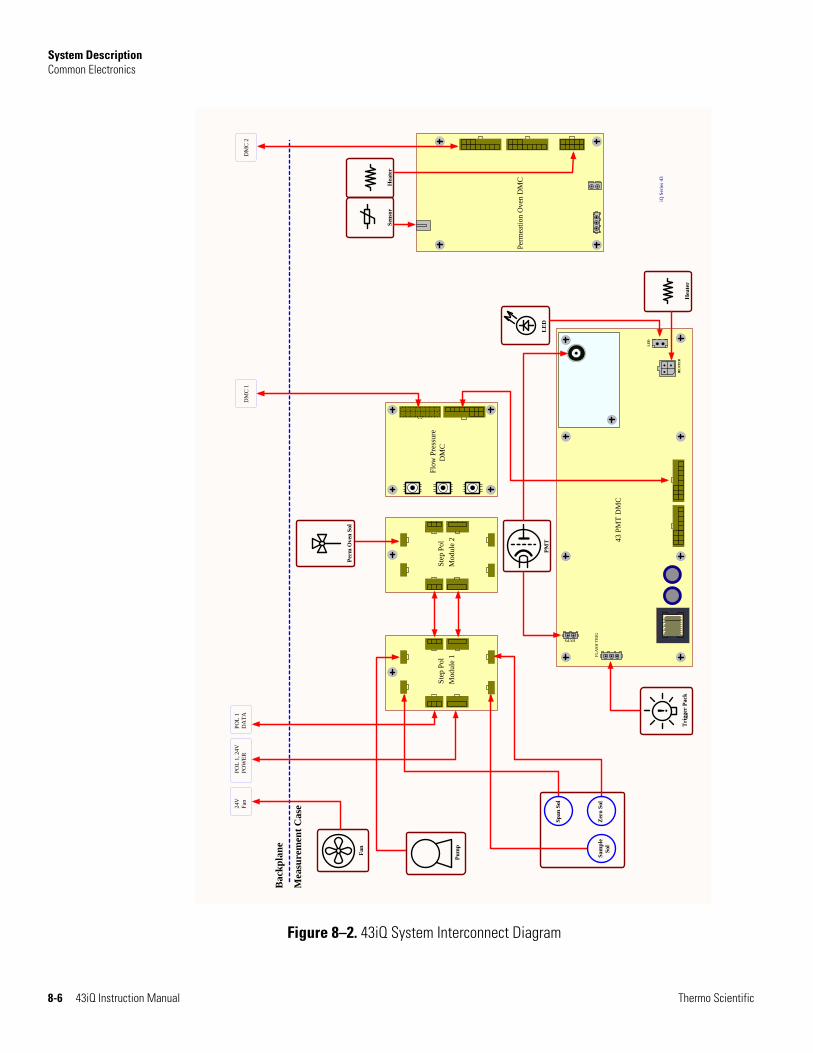
System Description Common Electronics
8-6 43iQ Instruction Manual Thermo Scientific
43 P
MT
DM
C
HVPS
LE
D
FL
AS
H T
RIG
HE
AT
ER
Flo
w P
ress
ure
DM
CS
tep
Pol
Ste
p P
ol
Zer
o So
l
Span
Sol
Sam
ple
Sol
Bac
kpla
ne
Mea
sure
men
t Cas
e
POL
1D
AT
APO
L 1
, 24V
POW
ER
DM
C 1
DM
C 2
Pum
p
Perm
Ove
n So
l
Fan
Fan
24V
!T
rigg
er P
ack
PMT
LE
D
Hea
ter
iQ S
erie
s 43
Mod
ule
1M
odul
e 2
Per
mea
tion
Ove
n D
MC
Sens
orH
eate
r
Figure 8–2. 43iQ System Interconnect Diagram

System Description Common Electronics
Thermo Scientific 43iQ Instruction Manual 8-7
All electronics operate from a universal VDC supply, which is capable of auto-sensing the input voltage and working over all specified operating ranges. The 43iQ contains a 24 VDC channel for most electronics operation, including the pump and fan, and a 48 VDC channel dedicated specifically for optical bench heating.
Front panel electronic components include the touch screen display, the on off switch, and two indicator LEDs for power and alarm status, as described in operational detail in Chapter 2, “Installation and Setup”.
The iQ series instruments provide a number of methods for communicating the instrument results to the operator or external equipment. Every iQ series instrument includes a front panel display, 2 USB ports, and one Ethernet data port as standard equipment.
In addition, optional RS-232/485, analog I/O, and digital I/O ports are available to provide data to external systems as described in Chapter 9, “Optional Equipment”. The front panel GUI allows the operator to configure these output communication channels as described in Chapter 3, “Operation”.
The System Controller Board (SCB) contains the main processor, power supplies, and a sub-processor, and serves as the communication hub for the instrument. The SCB receives operator inputs from the front panel GUI and/or over optional I/O connections on the rear panel. The SCB sends commands to the other boards to control the functions of the instrument and to collect measurement and diagnostic information. The SCB outputs instrument status and measurement data to the GUI, Ethernet/USB, and to the optional rear-panel I/O. The SCB plugs into the backplane via a single connector and has physical retainers to secure placement.
The backplane board provides the routing and conditioning for +24 VDC (optional +48 VDC) and RS-485 communications within the instrument. It hosts the System Controller Board (SCB) and Peripherals Support Board (PSB) via direct plug ins, and similarly hosts optional I/O (communication, analog, and digital) with rear panel interfaces via direct plug in. It has connections for RS485 communication with and powering of DMCs and the Step POL Module. It additionally routes the front panel display and driver, external USB and Ethernet.
Power Supply
Front Panel
I/O and Communication
Components
System ControllerBoard
Backplane Board

System Description Peripherals Support System
8-8 43iQ Instruction Manual Thermo Scientific
The peripheral support system operates these additional devices that are needed, but do not require special feedback control or processing. These components are connected to a Peripherals Support Board (PSB).
The chassis fan provides air cooling of the active electronic components.
The STEP POL board provides high/low outputs for continuous operation or on/off states. The STEP POL board contains the basic circuitry to provide a programmable load to passive devices, either continuously, or on user or automated command. In the iQ Series instruments, the pump, solenoids, etc., are controlled off of the STEP POL board from commands generated via the PSB.
Internal vacuum pump for generating air/sample through the instrument
Optional solenoid valves for switching between sample, zero, and span gases, and other optional components.
The Flow/Pressure DMC is used measure instrument pressures that assure proper flow regulation and for sample pressure within the measurement bench for pressure corrections and compensation.
The DMC includes two pressure sensors that read 0-860 mmHg. These sensors are used with the coupled restricting capillary for flow control along with the downstream sample pump. The pressure differential determines the flow through the capillary. The upstream pressure is the measurement bench pressure, while the downstream pressure is at the pump inlet pressure.
Like the hardware, the firmware is modular and located within microprocessors distributed throughout the instrument. In the 43iQ, microprocessors containing firmware are located as follows:
● Optical Bench DMC
● Flow/Pressure DMC
● Peripherals Support Board
● Optional I/O (Communications, Digital, and Analog)
PeripheralsSupport System
Fan
STEP POL Board
Sample Pump
Solenoid ValvePanel
Flow/PressureDMC
Firmware
System Description Firmware
Thermo Scientific 43iQ Instruction Manual 8-9
● Optional Permeation Oven
The firmware contains the active controls for their application, as well as self-identification and configuration for “plug and play” style operation. Each are associated with specific registers of two types:
● Modbus registers that are communicated from each microprocessor to the System Controller Board (SCB) via internal RS-485
● SNMP registers that are maintained in the software and SCB for health and data processing computation
The Modbus communication system operates on 1 second intervals. Within those intervals, data treatment like integration (whether analog or digital) and servo control, are embedded in the module firmware. The SCB receives the 1 second updates for higher level “software” processing and control via SNMP registers, some of which is interfaced with the front panel Graphical User Interface (GUI).
In addition to the operating registers, the 43iQ stores a historical data log in a MySQL database. The memory is provided on the same micro SD card where the operating software resides, for which there is capability to store up to a year of data at 1 minute intervals. Chapter 3, “Operation” describes how this database is accessed and used including external memory downloads.

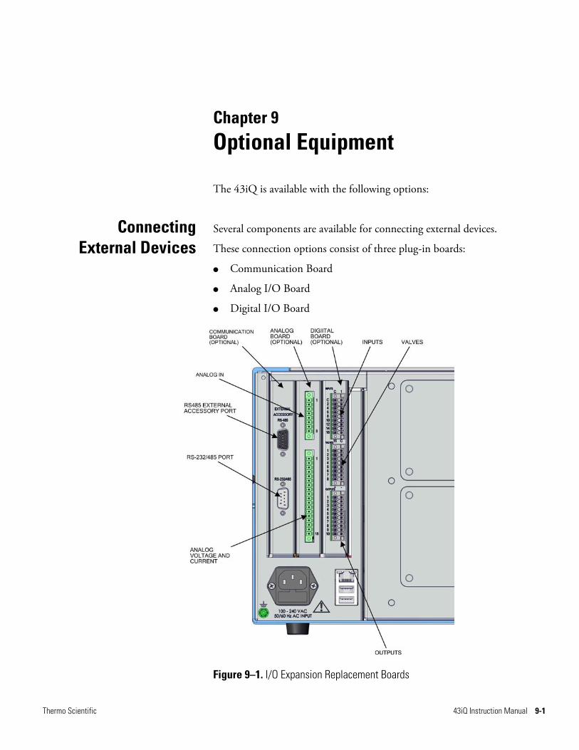
Thermo Scientific 43iQ Instruction Manual 9-1
Chapter 9
Optional Equipment
The 43iQ is available with the following options:
Several components are available for connecting external devices.
These connection options consist of three plug-in boards:
● Communication Board
● Analog I/O Board
● Digital I/O Board
Figure 9–1. I/O Expansion Replacement Boards
ConnectingExternal Devices
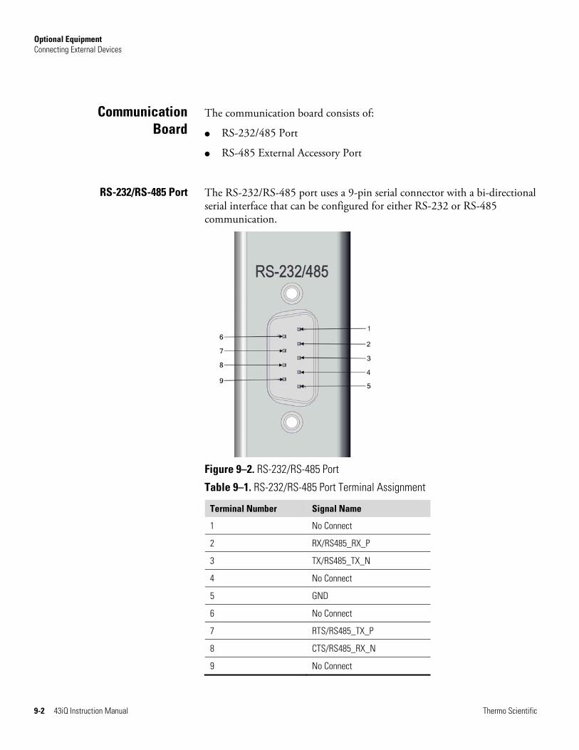
Optional Equipment Connecting External Devices
9-2 43iQ Instruction Manual Thermo Scientific
The communication board consists of:
● RS-232/485 Port
● RS-485 External Accessory Port
The RS-232/RS-485 port uses a 9-pin serial connector with a bi-directional serial interface that can be configured for either RS-232 or RS-485 communication.
Figure 9–2. RS-232/RS-485 Port
Table 9–1. RS-232/RS-485 Port Terminal Assignment
Terminal Number Signal Name
1 No Connect
2 RX/RS485_RX_P
3 TX/RS485_TX_N
4 No Connect
5 GND
6 No Connect
7 RTS/RS485_TX_P
8 CTS/RS485_RX_N
9 No Connect
CommunicationBoard
RS-232/RS-485 Port
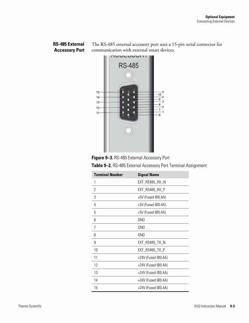
Optional Equipment Connecting External Devices
Thermo Scientific 43iQ Instruction Manual 9-3
The RS-485 external accessory port uses a 15-pin serial connector for communication with external smart devices.
Figure 9–3. RS-485 External Accessory Port
Table 9–2. RS-485 External Accessory Port Terminal Assignment
Terminal Number Signal Name
1 EXT_RS485_RX_N
2 EXT_RS485_RX_P
3 +5V (Fused @0.4A)
4 +5V (Fused @0.4A)
5 +5V (Fused @0.4A)
6 GND
7 GND
8 GND
9 EXT_RS485_TX_N
10 EXT_RS485_TX_P
11 +24V (Fused @0.4A)
12 +24V (Fused @0.4A)
13 +24V (Fused @0.4A)
14 +24V (Fused @0.4A)
15 +24V (Fused @0.4A)
RS-485 External Accessory Port

Optional Equipment Connecting External Devices
9-4 43iQ Instruction Manual Thermo Scientific
The Analog I/O Board consists of:
● 4 Isolated Analog Voltage Inputs, Input Voltage Range: 0–10 V
● 6 Isolated Analog Voltage Outputs, Three Ranges: 0–1.0 V, 0–5.0 V, 0–10 V
● 6 Isolated Analog Current Outputs, Two Ranges: 0mA–20mA, 4mA–20mA
Table 9–3 lists the analog voltage inputs are used to monitor four external 0–10V signals.
Figure 9–4. Analog Voltage Inputs
Table 9–3. Analog Voltage Inputs Assignment
Terminal Number Signal Name
1 Analog In 1
2 Analog GND
3 Analog In 2
4 Analog GND
5 Analog In 3
6 Analog GND
7 Analog In 4
8 Analog GND
Analog I/O Board
Analog Voltage Inputs

Optional Equipment Connecting External Devices
Thermo Scientific 43iQ Instruction Manual 9-5
There are six globally isolated, 16-bit, Analog Output channels, each with a Voltage Output, a Current Output and a common Return (isolated ground). The Analog Outputs are configured through the software control registers to select Voltage Output ranges 0–1 V, 0–5 V or 0–10 V, as well as Current Output ranges 0–20 mA or 4–20 mA. The maximum allowable load for each Current Output is 1000 Ω. All Voltage Outputs and Current Outputs are continuously monitored separately for accuracy.
The Analog Outputs may be used to control and report parameters pertinent to the analyzers’ measured functions.
Figure 9–5. Analog Voltage and Current
Analog Voltage Outputs

Optional Equipment Connecting External Devices
9-6 43iQ Instruction Manual Thermo Scientific
Table 9–4. Analog Voltage and Current Assignment
Terminal Number Signal Name
1 Current Out 1
2 Voltage Out 1
3 C/V Return 1
4 Current Out 2
5 Voltage Out 2
6 C/V Return 2
7 Current Out 3
8 Voltage Out 3
9 C/V Return 3
10 Current Out 4
11 Voltage Out 4
12 C/V Return 4
13 Current Out 5
14 Voltage Out 5
15 C/V Return 5
16 Current Out 6
17 Voltage Out 6
18 C/V Return 6
The iQ series instruments provide for the ability to calibrate the analog outputs (both voltage and current) of the instruments. The basic procedure for both voltage and current are the same using the following procedure:
● Complete the connections of the recording device to the desired analog output channel. (See page 9-5 for the channel information).
● Calibrate the output channel low level.
Note When calibrating the current output when using the 0-20 mA scale, the low level will be set to 4 mA due to the inability to adjust the actual current output to below zero. ▲
● Calibrate the output channel full scale.
Analog OutputCalibration

Optional Equipment Connecting External Devices
Thermo Scientific 43iQ Instruction Manual 9-7
Use the following procedure to calibrate the output channel to low level. This analog output calibration procedure reflects the zero calibration for analog output voltage for demonstration purposes. To calibrate the 4 mA current calibration, follow the same procedure, by selecting the 4 mA current calibration option.
Note This adjustment should only be performed by an instrument service technician. ▲
1. From the Home screen, choose Settings>Communications>Analog I/O>Analog Out Calibration.
2. Depending on the output type being used, select either Analog Out Zero Calibration (Voltage) or Analog Out 4.000 mA Calibration (Current).
3. A confirmation screen is presented. Select Continue to proceed with the calibration or Return to Previous Screen.
Analog Output ZeroCalibration
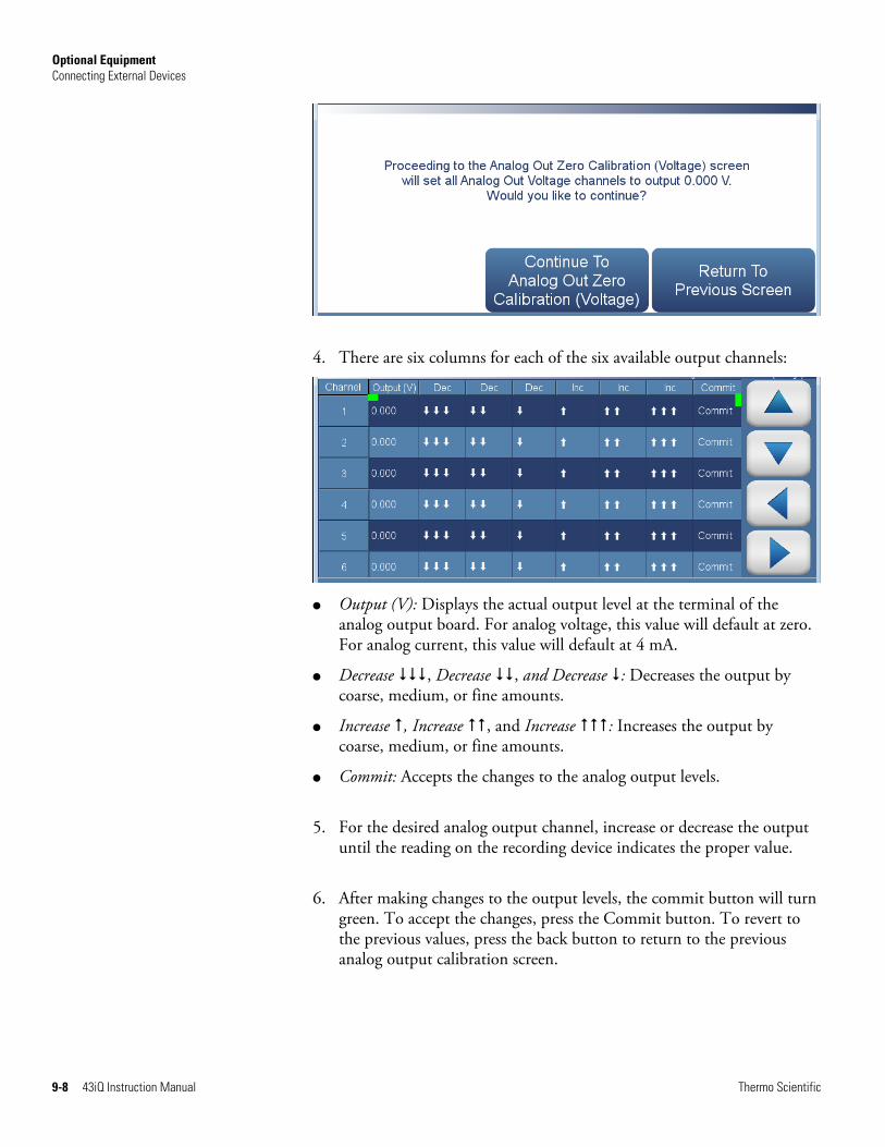
Optional Equipment Connecting External Devices
9-8 43iQ Instruction Manual Thermo Scientific
4. There are six columns for each of the six available output channels:
● Output (V): Displays the actual output level at the terminal of the
analog output board. For analog voltage, this value will default at zero. For analog current, this value will default at 4 mA.
● Decrease , Decrease , and Decrease : Decreases the output by coarse, medium, or fine amounts.
● Increase , Increase , and Increase : Increases the output by coarse, medium, or fine amounts.
● Commit: Accepts the changes to the analog output levels.
5. For the desired analog output channel, increase or decrease the output until the reading on the recording device indicates the proper value.
6. After making changes to the output levels, the commit button will turn green. To accept the changes, press the Commit button. To revert to the previous values, press the back button to return to the previous analog output calibration screen.
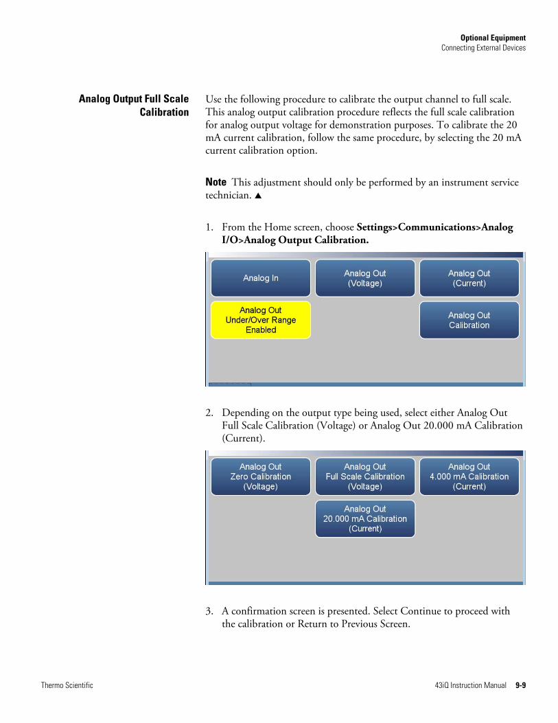
Optional Equipment Connecting External Devices
Thermo Scientific 43iQ Instruction Manual 9-9
Use the following procedure to calibrate the output channel to full scale. This analog output calibration procedure reflects the full scale calibration for analog output voltage for demonstration purposes. To calibrate the 20 mA current calibration, follow the same procedure, by selecting the 20 mA current calibration option.
Note This adjustment should only be performed by an instrument service technician. ▲
1. From the Home screen, choose Settings>Communications>Analog I/O>Analog Output Calibration.
2. Depending on the output type being used, select either Analog Out Full Scale Calibration (Voltage) or Analog Out 20.000 mA Calibration (Current).
3. A confirmation screen is presented. Select Continue to proceed with the calibration or Return to Previous Screen.
Analog Output Full ScaleCalibration

Optional Equipment Connecting External Devices
9-10 43iQ Instruction Manual Thermo Scientific
4. There are six columns for each of the six available output channels:
● Output (V): Displays the actual output level at the terminal of the
analog output board. For analog voltage, this value will default at the setting of the output channel, 1, 5, or 10 V. For analog current, this value will default at 20 mA.
● Decrease , Decrease , and Decrease : Decreases the output by coarse, medium, or fine amounts.
● Increase , Increase , and Increase : Increases the output by coarse, medium, or fine amounts.
● Commit: Accepts the changes to the analog output levels.
5. For the desired analog output channel, increase or decrease the output until the reading on the recording device indicates the proper value.
6. After making changes to the output levels, the commit button will turn green. To accept the changes, press the Commit button. To revert to the previous values, press the back button to return to the previous analog output calibration screen.

Optional Equipment Connecting External Devices
Thermo Scientific 43iQ Instruction Manual 9-11
The digital I/O board consists of:
● 16 Digital Inputs (18 pin connector)
● 10 Digital Relay Switches (20 pin connector)
● 8 Valve Driver Outputs (16 pin connector)
The digital inputs are TTL (3 V or 5 V) compatible and are pulled high within the instrument. The active state can be user defined in firmware.
● Logic Low Threshold: 0.8 V
● Logic High Threshold: 2.0 V
● Absolute allowable input voltages: -0.5 to 5.5 V
Figure 9–6. Digital Inputs
Digital I/O Board
Digital Inputs

Optional Equipment Connecting External Devices
9-12 43iQ Instruction Manual Thermo Scientific
Table 9–5. Digital Inputs Terminal Assignment
Terminal Number Signal Name
COMMON
1 Digital In 1
2 Digital In 2
3 Digital In 3
4 Digital In 4
5 Digital In 5
6 Digital In 6
7 Digital In 7
8 Digital In 8
9 Digital In 9
10 Digital In 10
11 Digital In 11
12 Digital In 12
13 Digital In 13
14 Digital In 14
15 Digital In 15
16 Digital In 16
COMMON
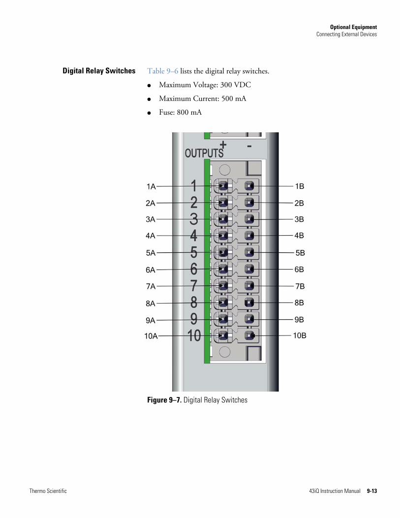
Optional Equipment Connecting External Devices
Thermo Scientific 43iQ Instruction Manual 9-13
Table 9–6 lists the digital relay switches.
● Maximum Voltage: 300 VDC
● Maximum Current: 500 mA
● Fuse: 800 mA
Figure 9–7. Digital Relay Switches
Digital Relay Switches

Optional Equipment Connecting External Devices
9-14 43iQ Instruction Manual Thermo Scientific
Table 9–6. Digital Relay Switch Assignment
Terminal Number Signal Name
1A Relay 1A
1B Relay 1B
2A Relay 2A
2B Relay 2B
3A Relay 3A
3B Relay 3B
4A Relay 4A
4B Relay 4B
5A Relay 5A
5B Relay 5B
6A Relay 6A
6B Relay 6B
7A Relay 7A
7B Relay 7B
8A Relay 8A
8B Relay 8B
9A Relay 9A
9B Relay 9B
10A Relay 10A
10B Relay 10B

Optional Equipment Connecting External Devices
Thermo Scientific 43iQ Instruction Manual 9-15
Table 9–7 lists the valve driver outputs.
● Actual Output Voltage: 2224 VDC
● Maximum Current: 300 mA
● Both positive and negative outputs are protected from over voltage and over current by 500 mA fuses.
Figure 9–8. Valve Driver Outputs
Valve Driver Outputs
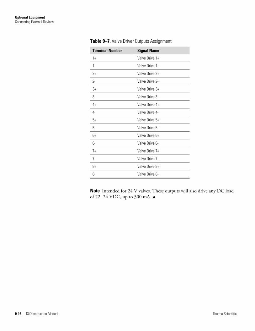
Optional Equipment Connecting External Devices
9-16 43iQ Instruction Manual Thermo Scientific
Table 9–7. Valve Driver Outputs Assignment
Terminal Number Signal Name
1+ Valve Drive 1+
1- Valve Drive 1-
2+ Valve Drive 2+
2- Valve Drive 2-
3+ Valve Drive 3+
3- Valve Drive 3-
4+ Valve Drive 4+
4- Valve Drive 4-
5+ Valve Drive 5+
5- Valve Drive 5-
6+ Valve Drive 6+
6- Valve Drive 6-
7+ Valve Drive 7+
7- Valve Drive 7-
8+ Valve Drive 8+
8- Valve Drive 8-
Note Intended for 24 V valves. These outputs will also drive any DC load of 2224 VDC, up to 300 mA. ▲
Optional Equipment Internal Zero/Span and Sample Valves
Thermo Scientific 43iQ Instruction Manual 9-17
With the zero/span assembly option, a source of span gas is connected to the SPAN port and a source of zero air is connected to the ZERO IN port. It may be necessary to use an atmospheric dump bypass plumbing arrangement to accomplish this.
For more information, refer to the “Installation and Setup” chapter and the “Operation” chapter.
The Internal Permeation Span Source option is designed to provide a simple span check. This option is intended as a quick, convenient check to be used between zero and span calibrations for determining instrument malfunction or drift. Because this option does not precisely control dilution gas flow, it should not be used as a basis for instrument zero and span adjustments, calibration updates or adjustment of ambient data.
Whenever there is an indication of possible instrument drift or malfunction, a full zero and calibration (Level 1) should be performed prior to corrective action. For further information on zero, span and calibration of air pollution monitors, refer to Section 2.0.9 of the US EPA's Quality Assurance Handbook for Air Pollution Measurement Systems (Volume II).
Figure 9–9 shows how this option is integrated with the 43iQ components. During normal operation, the pump draws zero air through the permeation oven and out the instrument exhaust. When performing a single point span check, the sample valve is energized, closing the sample valve, and the Perm valve is energized, opening the perm valve. This directs the zero air/SO2 gas mixture from the permeation oven gas through the heated hydrocarbon kicker and into the optical bench.
Internal Zero/Spanand Sample Valves
Internal Permeation Span
Source

Optional Equipment Internal Permeation Span Source
9-18 43iQ Instruction Manual Thermo Scientific
Figure 9–9. Internal Permeation Span Source Flow Diagram
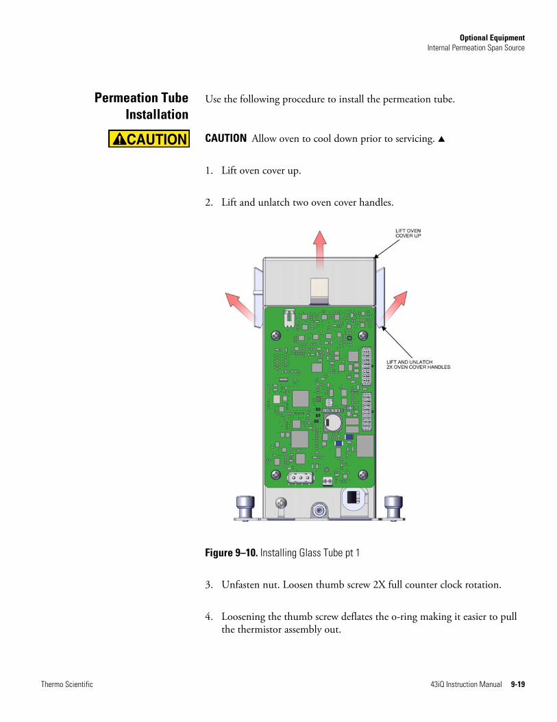
Optional Equipment Internal Permeation Span Source
Thermo Scientific 43iQ Instruction Manual 9-19
Use the following procedure to install the permeation tube.
CAUTION Allow oven to cool down prior to servicing. ▲
1. Lift oven cover up.
2. Lift and unlatch two oven cover handles.
Figure 9–10. Installing Glass Tube pt 1
3. Unfasten nut. Loosen thumb screw 2X full counter clock rotation.
4. Loosening the thumb screw deflates the o-ring making it easier to pull the thermistor assembly out.
Permeation TubeInstallation
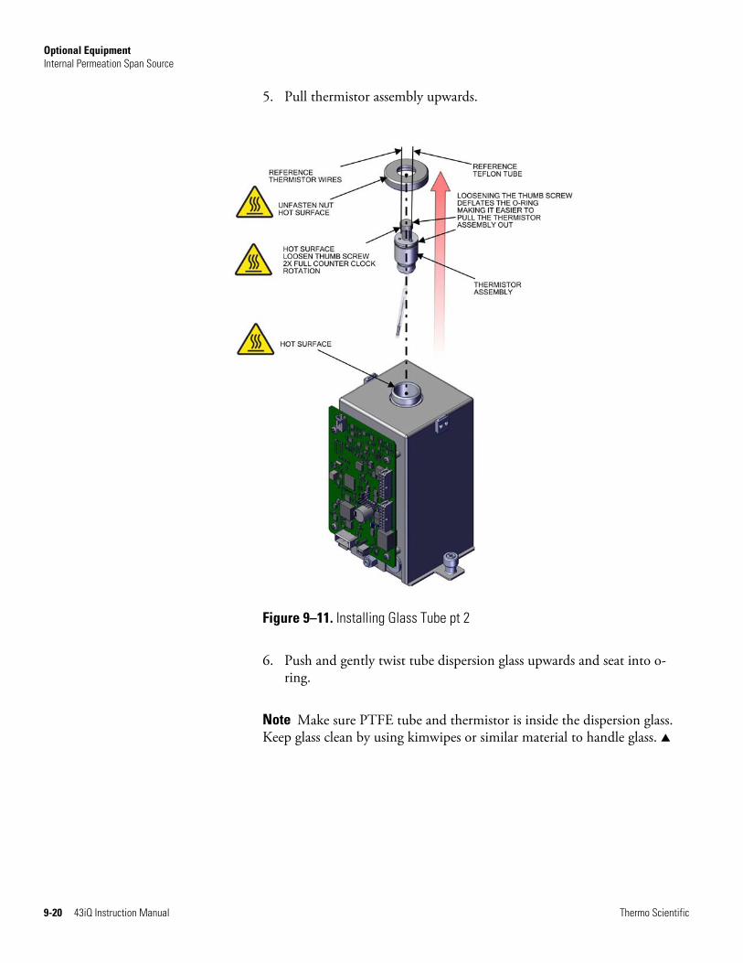
Optional Equipment Internal Permeation Span Source
9-20 43iQ Instruction Manual Thermo Scientific
5. Pull thermistor assembly upwards.
Figure 9–11. Installing Glass Tube pt 2
6. Push and gently twist tube dispersion glass upwards and seat into o-ring.
Note Make sure PTFE tube and thermistor is inside the dispersion glass. Keep glass clean by using kimwipes or similar material to handle glass. ▲
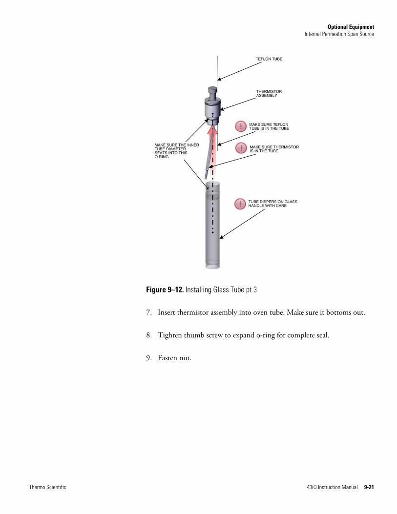
Optional Equipment Internal Permeation Span Source
Thermo Scientific 43iQ Instruction Manual 9-21
Figure 9–12. Installing Glass Tube pt 3
7. Insert thermistor assembly into oven tube. Make sure it bottoms out.
8. Tighten thumb screw to expand o-ring for complete seal.
9. Fasten nut.

Optional Equipment Internal Permeation Span Source
9-22 43iQ Instruction Manual Thermo Scientific
Figure 9–13. Installing Glass Tube pt 4
10. Latch oven cover handles.
The computation of SO2 output level is shown in the following information. Note that is assumed that all devices are properly calibrated and that all flows are corrected to 25 °C and 1 atm.
Permeation Tube:
Q
(K) (R) = (ppm) Output
o
Where:
R = permeation rate in ng/min
Q0 = flow rate of gas (scc/min) into the charcoal scrubber during span mode
K = constant for the specific permeant = 24.45 / MW
MW = molecular weight
Computation ofConcentrations

Optional Equipment PTFE Particulate Filter
Thermo Scientific 43iQ Instruction Manual 9-23
A 5-10 micron pore size, two-inch diameter PTFE element is available for the 43iQ. This filter should be installed just prior to the SAMPLE bulkhead. When using a filter, all calibrations and span checks must be performed through the filter.
The 43iQ ships standard with a capillary to maintain the instrument flow rate at approximately 0.5 LPM. An optional capillary is available that will maintain the instrument flow at approximately 1.0 LPM. This increased flow may be desirable when a reduced instrument response time is desired.
To run the higher flow rate, replace the instrument capillary with a 0.02 size capillary. (Refer to “43iQ Measurement Case” in the iQ Series Gas Analyzer Spare Parts Catalog for part number.)
From the Home Screen, press Configuration>High Flow to enable the high flow option.
PTFE ParticulateFilter
High Flow Option


Thermo Scientific 43iQ Instruction Manual A-1
Appendix A
Safety, Warranty, and WEEE
Review the following information carefully before using the instrument. This manual provides specific information on how to operate the instrument, however if the instrument is used in a manner not specified by the manufacturer, the protection provided by the equipment may be impaired.
This manual contains important information to alert you to potential safety hazards and risks of equipment damage. Refer to the following types of alerts you may see in this manual.
Safety and Equipment Damage Alert Descriptions
Alert Description
A hazard is present that will result in death or serious personal injury if the warning is ignored. ▲
A hazard is present or an unsafe practice can result in serious personal injury if the warning is ignored. ▲
The hazard or unsafe practice could result in minor to moderate personal injury if the warning is ignored. ▲
Equipment Damage The hazard or unsafe practice could result in property damage if the warning is ignored. ▲
Safety and Equipment Damage Alerts in this Manual
Alert Description
If the equipment is operated in a manner not specified by the manufacturer, the protection provided by the equipment may be impaired. ▲
The service procedures in this manual are restricted to qualified service personnel only. ▲
Equipment Damage Do not attempt to lift the analyzer by the cover or other external fittings. ▲
This adjustment should only be performed by an instrument service technician. ▲
Safety
Safety andEquipment Damage
Alerts

Safety, Warranty, and WEEE Warranty
A-2 43iQ Instruction Manual Thermo Scientific
Seller warrants that the Products will operate or perform substantially in conformance with Seller's published specifications and be free from defects in material and workmanship, when subjected to normal, proper and intended usage by properly trained personnel, for the period of time set forth in the product documentation, published specifications or package inserts. If a period of time is not specified in Seller’s product documentation, published specifications or package inserts, the warranty period shall be one (1) year from the date of shipment to Buyer for equipment and ninety (90) days for all other products (the "Warranty Period"). Seller agrees during the Warranty Period, to repair or replace, at Seller's option, defective Products so as to cause the same to operate in substantial conformance with said published specifications; provided that (a) Buyer shall promptly notify Seller in writing upon the discovery of any defect, which notice shall include the product model and serial number (if applicable) and details of the warranty claim; (b) after Seller’s review, Seller will provide Buyer with service data and/or a Return Material Authorization (“RMA”), which may include biohazard decontamination procedures and other product-specific handling instructions; and (c) then, if applicable, Buyer may return the defective Products to Seller with all costs prepaid by Buyer. Replacement parts may be new or refurbished, at the election of Seller. All replaced parts shall become the property of Seller. Shipment to Buyer of repaired or replacement Products shall be made in accordance with the Delivery provisions of the Seller’s Terms and Conditions of Sale. Consumables, including but not limited to lamps, fuses, batteries, bulbs and other such expendable items, are expressly excluded from the warranty under this warranty.
Notwithstanding the foregoing, Products supplied by Seller that are obtained by Seller from an original manufacturer or third party supplier are not warranted by Seller, but Seller agrees to assign to Buyer any warranty rights in such Product that Seller may have from the original manufacturer or third party supplier, to the extent such assignment is allowed by such original manufacturer or third party supplier.
In no event shall Seller have any obligation to make repairs, replacements or corrections required, in whole or in part, as the result of (i) normal wear and tear, (ii) accident, disaster or event of force majeure, (iii) misuse, fault or negligence of or by Buyer, (iv) use of the Products in a manner for which they were not designed, (v) causes external to the Products such as, but not limited to, power failure or electrical power surges, (vi) improper storage and handling of the Products or (vii) use of the Products in combination with equipment or software not supplied by Seller. If Seller determines that Products for which Buyer has requested warranty services are not covered by the warranty hereunder, Buyer shall pay or reimburse Seller for all costs of investigating and responding to such request at Seller's then
Warranty
Safety, Warranty, and WEEE Warranty
Thermo Scientific 43iQ Instruction Manual A-3
prevailing time and materials rates. If Seller provides repair services or replacement parts that are not covered by the warranty provided in this warranty, Buyer shall pay Seller therefor at Seller's then prevailing time and materials rates. ANY INSTALLATION, MAINTENANCE, REPAIR, SERVICE, RELOCATION OR ALTERATION TO OR OF, OR OTHER TAMPERING WITH, THE PRODUCTS PERFORMED BY ANY PERSON OR ENTITY OTHER THAN SELLER WITHOUT SELLER'S PRIOR WRITTEN APPROVAL, OR ANY USE OF REPLACEMENT PARTS NOT SUPPLIED BY SELLER, SHALL IMMEDIATELY VOID AND CANCEL ALL WARRANTIES WITH RESPECT TO THE AFFECTED PRODUCTS.
THE OBLIGATIONS CREATED BY THIS WARRANTY STATEMENT TO REPAIR OR REPLACE A DEFECTIVE PRODUCT SHALL BE THE SOLE REMEDY OF BUYER IN THE EVENT OF A DEFECTIVE PRODUCT. EXCEPT AS EXPRESSLY PROVIDED IN THIS WARRANTY STATEMENT, SELLER DISCLAIMS ALL OTHER WARRANTIES, WHETHER EXPRESS OR IMPLIED, ORAL OR WRITTEN, WITH RESPECT TO THE PRODUCTS, INCLUDING WITHOUT LIMITATION ALL IMPLIED WARRANTIES OF MERCHANTABILITY OR FITNESS FOR ANY PARTICULAR PURPOSE. SELLER DOES NOT WARRANT THAT THE PRODUCTS ARE ERROR-FREE OR WILL ACCOMPLISH ANY PARTICULAR RESULT.

Safety, Warranty, and WEEE WEEE Compliance
A-4 43iQ Instruction Manual Thermo Scientific
This product is required to comply with the European Union’s Waste Electrical & Electronic Equipment (WEEE) Directive 2002/96/EC. It is marked with the following symbol:
Thermo Fisher Scientific has contracted with one or more recycling/disposal companies in each EU Member State, and this product should be disposed of or recycled through them. Further information on Thermo Fisher Scientific’s compliance with these Directives, the recyclers in your country, and information on Thermo Fisher Scientific products which may assist the detection of substances subject to the RoHS Directive are available at: www.thermoscientific.com/WEEERoHS.
The following symbol and description identify the WEEE marking used on the instrument and in the associated documentation.
Symbol Description
Marking of electrical and electronic equipment which applies to electrical and electronic equipment falling under the Directive 2002/96/EC (WEEE) and the equipment that has been put on the market after 13 August 2005. ▲
WEEE Compliance
WEEE Symbol
Thermo Scientific 43iQ Instruction Manual B-1
Appendix B
Quick Reference
Figure 1–1. 43iQ Front ........................................................................................ 1-2 Figure 1–2. 43iQ Flow Schematic ....................................................................... 1-4 Figure 1–3. 43iQ Flow Schematic with Zero Span ............................................. 1-4 Figure 1–4. Bench Mount Assembly (dimensions in inches [mm]) .................... 1-7 Figure 1–5. Rack Mount Assembly (dimensions in inches [mm]) ...................... 1-8 Figure 1–6. Rack Mount Requirements .............................................................. 1-9 Figure 1–7. Rack Requirements Part 2 ............................................................... 1-9 Figure 2–1. Removing the Cover......................................................................... 2-2 Figure 2–2. Installing Feet .................................................................................. 2-3 Figure 2–3. Removing the Front Panel ............................................................... 2-4 Figure 2–4. Installing Ears and Handles ............................................................. 2-5 Figure 2–5. 43iQ Rear Panel ............................................................................... 2-7 Figure 2–6. Atmospheric Dump Bypass Plumbing ............................................. 2-7 Figure 2–7. Front Panel and Touchscreen Display ............................................. 2-8 Figure 4–1. Cylinder Gas Dilution System .......................................................... 4-3 Figure 4–2. Permeation Tube System ................................................................ 4-5 Figure 5–1. Single Stage Pump .......................................................................... 5-2 Figure 5–2. Pump Rebuilding .............................................................................. 5-4 Figure 7–1. Properly Grounded Antistatic Wrist Strap ...................................... 7-2 Figure 7–2. 43iQ Component Layout Top View .................................................. 7-4 Figure 7–3. 43iQ Component Layout Side View ................................................. 7-4 Figure 7–4. Replacing the Fuses ......................................................................... 7-5 Figure 7–5. Start with Top Right Corner of Fan Cover ....................................... 7-6 Figure 7–6. Removing the Fan Cover .................................................................. 7-6 Figure 7–7. Unplugging the Fan Cable ............................................................... 7-7 Figure 7–8. Replacing the Fan ............................................................................ 7-8 Figure 7–9. Unplugging the Fan Cable ............................................................... 7-9 Figure 7–10. Unplugging the DMC Cable ......................................................... 7-10 Figure 7–11. Unfasten Hardware Front for Measurement Side Removal ....... 7-10 Figure 7–12. Unfasten Hardware Rear for Measurement Side Removal ........ 7-11 Figure 7–13. Replacing the LCD Module .......................................................... 7-12 Figure 7–14. Remove Electrical Cables from LCD ............................................ 7-13
List of Figures
Quick Reference List of Figures
B-2 43iQ Instruction Manual Thermo Scientific
Figure 7–15. I/O Replacement, Arm ................................................................. 7-14 Figure 7–16. I/O Replacement, Remove Board ................................................ 7-14 Figure 7–17. I/O Replacement, Install .............................................................. 7-15 Figure 7–18. I/O Replacement, Close Arm Alignment ..................................... 7-15 Figure 7–19. Replacing the Peripherals Support Board ................................... 7-16 Figure 7–20. Flow Pressure Board, Disconnect DMC Cable ............................ 7-17 Figure 7–21. Flow Pressure Board, Screws ...................................................... 7-18 Figure 7–22. Remove Pump, Disconnect and Unfasten ................................... 7-20 Figure 7–23. Pump Removal, Keyway ............................................................... 7-21 Figure 7–24. Pump replacing, Unfasten Screws .............................................. 7-21 Figure 7–25. Remove Capillary, Disconnect and Unfasten .............................. 7-22 Figure 7–26. Capillary Plate, Keyway ............................................................... 7-23 Figure 7–27. Capillary and O-Ring Replace ...................................................... 7-23 Figure 7–28. Removing Power Supply .............................................................. 7-25 Figure 7–29. Replacing Power Supply .............................................................. 7-25 Figure 7–30. Unplug and Unfasten Step POL Board ......................................... 7-26 Figure 7–31. Clear Partition Keyway Step POL Board ...................................... 7-27 Figure 7–32. Step POL Board 1 Switch Settings .............................................. 7-28 Figure 7–33. Optional Step POL Board 2 Switch Settings ............................... 7-28 Figure 7–34. Removing the DMC Optical Bench Removal from Instrument .... 7-30 Figure 7–35. Removing the Optical Bench Assembly ....................................... 7-31 Figure 7–36. Removing the Optical Bench Assembly pt 2 ............................... 7-32 Figure 7–37. Removing the PMT Assembly ...................................................... 7-33 Figure 7–38. Removing the PMT Cover ............................................................ 7-34 Figure 7–39. Replacing the PMT ....................................................................... 7-34 Figure 7–40. Removing and Replacing the Flasher Pack .................................. 7-35 Figure 7–41. Replacing the Flasher Pack Lamp ................................................ 7-36 Figure 7–42. Replacing the Photo Lamp Detector Board pt 1 .......................... 7-37 Figure 7–43. Replacing the Photo Lamp Detector board pt 2 .......................... 7-38 Figure 7–44. Removing and Replacing the Kicker Assembly ........................... 7-39 Figure 7–45. Replacing the Manifold pt 1 ........................................................ 7-40 Figure 7–46. Replacing the Manifold pt 2 ........................................................ 7-41 Figure 7–47. Replacing the Manifold pt 3 ........................................................ 7-41 Figure 7–48. Removing and Replacing the Solenoid Valve pt 1 ...................... 7-42 Figure 7–49. Removing and Replacing the Solenoid Valve pt 2 ...................... 7-43 Figure 7–50. Perm Oven pt 1 ............................................................................. 7-44 Figure 7–51. Finger Push and Release Tubing ................................................. 7-45 Figure 7–52. Perm Oven Replacement pt 2 ...................................................... 7-46 Figure 7–53. Replacing the Permeation Oven Board ........................................ 7-47 Figure 8–1. Common System Interconnect Diagram .......................................... 8-5

Quick Reference List of Tables
Thermo Scientific 43iQ Instruction Manual B-3
Figure 8–2. 43iQ System Interconnect Diagram ................................................ 8-6 Figure 9–1. I/O Expansion Replacement Boards ................................................ 9-1 Figure 9–2. RS-232/RS-485 Port......................................................................... 9-2 Figure 9–3. RS-485 External Accessory Port ...................................................... 9-3 Figure 9–4. Analog Voltage Inputs ..................................................................... 9-4 Figure 9–5. Analog Voltage and Current ............................................................ 9-5 Figure 9–6. Digital Inputs ................................................................................. 9-11 Figure 9–7. Digital Relay Switches .................................................................. 9-13 Figure 9–8. Valve Driver Outputs ..................................................................... 9-15 Figure 9–9. Internal Permeation Span Source Flow Diagram .......................... 9-18 Figure 9–10. Installing Glass Tube pt 1 ............................................................ 9-19 Figure 9–11. Installing Glass Tube pt 2 ............................................................ 9-20 Figure 9–12. Installing Glass Tube pt 3 ............................................................ 9-21 Figure 9–13. Installing Glass Tube pt 4 ............................................................ 9-22
Table 1–1. 43iQ Specifications ........................................................................... 1-5 Table 1–2. 43iQ Optional Permeation Oven Specifications ............................... 1-6 Table 6–1. 43iQ Troubleshooting Guide ............................................................. 6-1 Table 9–1. RS-232/RS-485 Port Terminal Assignment ...................................... 9-2 Table 9–2. RS-485 External Accessory Port Terminal Assignment ................... 9-3 Table 9–3. Analog Voltage Inputs Assignment .................................................. 9-4 Table 9–4. Analog Voltage and Current Assignment ......................................... 9-6 Table 9–5. Digital Inputs Terminal Assignment ............................................... 9-12 Table 9–6. Digital Relay Switch Assignment ................................................... 9-14 Table 9–7. Valve Driver Outputs Assignment .................................................. 9-16
List of Tables


Thermo Scientific 43iQ Instruction Manual C-1
Appendix C
GNU Lesser General Public License
Version 2.1, February 1999
Copyright (C) 1991, 1999 Free Software Foundation, Inc.
51 Franklin Street, Fifth Floor, Boston, MA 02110-1301 USA
Everyone is permitted to copy and distribute verbatim copies of this license document, but changing it is not allowed.
BECAUSE THE LIBRARY IS LICENSED FREE OF CHARGE, THERE IS NO WARRANTY FOR THE LIBRARY, TO THE EXTENT PERMITTED BY APPLICABLE LAW.
The Open Source code used in the development of this product will be provided for a period of 3-years from date of purchase to the original purchaser provided they supply Thermo Fisher Scientific with the applicable serial number for the product the Open Source code is being requested for.
[This is the first released version of the Lesser GPL. It also counts as the successor of the GNU Library Public License, version 2, hence the version number 2.1.]
Preamble
The licenses for most software are designed to take away your freedom to share and change it. By contrast, the GNU General Public Licenses are intended to guarantee your freedom to share and change free software--to make sure the software is free for all its users.
This license, the Lesser General Public License, applies to some specially designated software packages--typically libraries--of the Free Software Foundation and other authors who decide to use it. You can use it too, but we suggest you first think carefully about whether this license or the ordinary General Public License is the better strategy to use in any particular case, based on the explanations below.
When we speak of free software, we are referring to freedom of use, not price. Our General Public Licenses are designed to make sure that you have the freedom to distribute copies of free software (and charge for this service if you wish); that you receive source code or can get it if you want it;
GNU LesserGeneral Public
License
GNU Lesser General Public License GNU Lesser General Public License
C-2 43iQ Instruction Manual Thermo Scientific
that you can change the software and use pieces of it in new free programs; and that you are informed that you can do these things.
To protect your rights, we need to make restrictions that forbid distributors to deny you these rights or to ask you to surrender these rights. These restrictions translate to certain responsibilities for you if you distribute copies of the library or if you modify it.
For example, if you distribute copies of the library, whether gratis or for a fee, you must give the recipients all the rights that we gave you. You must make sure that they, too, receive or can get the source code. If you link other code with the library, you must provide complete object files to the recipients, so that they can relink them with the library after making changes to the library and recompiling it. And you must show them these terms so they know their rights.
We protect your rights with a two-step method: (1) we copyright the library, and (2) we offer you this license, which gives you legal permission to copy, distribute and/or modify the library.
To protect each distributor, we want to make it very clear that there is no warranty for the free library. Also, if the library is modified by someone else and passed on, the recipients should know that what they have is not the original version, so that the original author's reputation will not be affected by problems that might be introduced by others.
Finally, software patents pose a constant threat to the existence of any free program. We wish to make sure that a company cannot effectively restrict the users of a free program by obtaining a restrictive license from a patent holder. Therefore, we insist that any patent license obtained for a version of the library must be consistent with the full freedom of use specified in this license.
Most GNU software, including some libraries, is covered by the ordinary GNU General Public License. This license, the GNU Lesser General Public License, applies to certain designated libraries, and is quite different from the ordinary General Public License. We use this license for certain libraries in order to permit linking those libraries into non-free programs.
When a program is linked with a library, whether statically or using a shared library, the combination of the two is legally speaking a combined work, a derivative of the original library. The ordinary General Public License therefore permits such linking only if the entire combination fits its criteria of freedom. The Lesser General Public License permits more lax criteria for linking other code with the library.
We call this license the "Lesser" General Public License because it does Less to protect the user's freedom than the ordinary General Public License. It also provides other free software developers Less of an advantage over competing non-free programs. These disadvantages are the reason we use

GNU Lesser General Public License GNU Lesser General Public License
Thermo Scientific 43iQ Instruction Manual C-3
the ordinary General Public License for many libraries. However, the Lesser license provides advantages in certain special circumstances.
For example, on rare occasions, there may be a special need to encourage the widest possible use of a certain library, so that it becomes a de-facto standard. To achieve this, non-free programs must be allowed to use the library. A more frequent case is that a free library does the same job as widely used non-free libraries. In this case, there is little to gain by limiting the free library to free software only, so we use the Lesser General Public License.
In other cases, permission to use a particular library in non-free programs enables a greater number of people to use a large body of free software. For example, permission to use the GNU C Library in non-free programs enables many more people to use the whole GNU operating system, as well as its variant, the GNU/Linux operating system.
Although the Lesser General Public License is Less protective of the users' freedom, it does ensure that the user of a program that is linked with the Library has the freedom and the wherewithal to run that program using a modified version of the Library.
The precise terms and conditions for copying, distribution and modification follow. Pay close attention to the difference between a "work based on the library" and a "work that uses the library". The former contains code derived from the library, whereas the latter must be combined with the library in order to run.
GNU LESSER GENERAL PUBLIC LICENSE TERMS AND CONDITIONS FOR COPYING, DISTRIBUTION AND MODIFICATION
0. This License Agreement applies to any software library or other program which contains a notice placed by the copyright holder or other authorized party saying it may be distributed under the terms of this Lesser General Public License (also called "this License"). Each licensee is addressed as "you".
A "library" means a collection of software functions and/or data prepared so as to be conveniently linked with application programs (which use some of those functions and data) to form executables.
The "Library", below, refers to any such software library or work which has been distributed under these terms. A "work based on the Library" means either the Library or any derivative work under copyright law: that is to say, a work containing the Library or a portion of it, either verbatim or with modifications and/or translated straightforwardly into another language. (Hereinafter, translation is included without limitation in the term "modification".)

GNU Lesser General Public License GNU Lesser General Public License
C-4 43iQ Instruction Manual Thermo Scientific
"Source code" for a work means the preferred form of the work for making modifications to it. For a library, complete source code means all the source code for all modules it contains, plus any associated interface definition files, plus the scripts used to control compilation and installation of the library.
Activities other than copying, distribution and modification are not covered by this License; they are outside its scope. The act of running a program using the Library is not restricted, and output from such a program is covered only if its contents constitute a work based on the Library (independent of the use of the Library in a tool for writing it). Whether that is true depends on what the Library does and what the program that uses the Library does.
1. You may copy and distribute verbatim copies of the Library's complete source code as you receive it, in any medium, provided that you conspicuously and appropriately publish on each copy an appropriate copyright notice and disclaimer of warranty; keep intact all the notices that refer to this License and to the absence of any warranty; and distribute a copy of this License along with the Library.
You may charge a fee for the physical act of transferring a copy, and you may at your option offer warranty protection in exchange for a fee.
2. You may modify your copy or copies of the Library or any portion of it, thus forming a work based on the Library, and copy and distribute such modifications or work under the terms of Section 1 above, provided that you also meet all of these conditions:
a) The modified work must itself be a software library.
b) You must cause the files modified to carry prominent notices stating that you changed the files and the date of any change.
c) You must cause the whole of the work to be licensed at no charge to all third parties under the terms of this License.
d) If a facility in the modified Library refers to a function or a table of data to be supplied by an application program that uses the facility, other than as an argument passed when the facility is invoked, then you must make a good faith effort to ensure that, in the event an application does not supply such function or table, the facility still operates, and performs whatever part of its purpose remains meaningful.
(For example, a function in a library to compute square roots has a purpose that is entirely well-defined independent of the application. Therefore, Subsection 2d requires that any application-supplied function or table used by this function must be optional: if the application does not supply it, the square root function must still compute square roots.)

GNU Lesser General Public License GNU Lesser General Public License
Thermo Scientific 43iQ Instruction Manual C-5
These requirements apply to the modified work as a whole. If identifiable sections of that work are not derived from the Library, and can be reasonably considered independent and separate works in themselves, then this License, and its terms, do not apply to those sections when you distribute them as separate works. But when you distribute the same sections as part of a whole which is a work based on the Library, the distribution of the whole must be on the terms of this License, whose permissions for other licensees extend to the entire whole, and thus to each and every part regardless of who wrote it.
Thus, it is not the intent of this section to claim rights or contest your rights to work written entirely by you; rather, the intent is to exercise the right to control the distribution of derivative or collective works based on the Library.
In addition, mere aggregation of another work not based on the Library with the Library (or with a work based on the Library) on a volume of a storage or distribution medium does not bring the other work under the scope of this License.
3. You may opt to apply the terms of the ordinary GNU General Public License instead of this License to a given copy of the Library. To do this, you must alter all the notices that refer to this License, so that they refer to the ordinary GNU General Public License, version 2, instead of to this License. (If a newer version than version 2 of the ordinary GNU General Public License has appeared, then you can specify that version instead if you wish.) Do not make any other change in these notices.
Once this change is made in a given copy, it is irreversible for that copy, so the ordinary GNU General Public License applies to all subsequent copies and derivative works made from that copy. This option is useful when you wish to copy part of the code of the Library into a program that is not a library.
4. You may copy and distribute the Library (or a portion or derivative of it, under Section 2) in object code or executable form under the terms of Sections 1 and 2 above provided that you accompany it with the complete corresponding machine-readable source code, which must be distributed under the terms of Sections 1 and 2 above on a medium customarily used for software interchange.
If distribution of object code is made by offering access to copy from a designated place, then offering equivalent access to copy the source code from the same place satisfies the requirement to distribute the source code, even though third parties are not compelled to copy the source along with the object code.
5. A program that contains no derivative of any portion of the Library, but is designed to work with the Library by being compiled or linked with it, is

GNU Lesser General Public License GNU Lesser General Public License
C-6 43iQ Instruction Manual Thermo Scientific
called a "work that uses the Library". Such a work, in isolation, is not a derivative work of the Library, and therefore falls outside the scope of this License.
However, linking a "work that uses the Library" with the Library creates an executable that is a derivative of the Library (because it contains portions of the Library), rather than a "work that uses the library". The executable is therefore covered by this License. Section 6 states terms for distribution of such executables.
When a "work that uses the Library" uses material from a header file that is part of the Library, the object code for the work may be a derivative work of the Library even though the source code is not. Whether this is true is especially significant if the work can be linked without the Library, or if the work is itself a library. The threshold for this to be true is not precisely defined by law.
If such an object file uses only numerical parameters, data structure layouts and accessors, and small macros and small inline functions (ten lines or less in length), then the use of the object file is unrestricted, regardless of whether it is legally a derivative work. (Executables containing this object code plus portions of the Library will still fall under Section 6.)
Otherwise, if the work is a derivative of the Library, you may distribute the object code for the work under the terms of Section 6. Any executables containing that work also fall under Section 6, whether or not they are linked directly with the Library itself.
6. As an exception to the Sections above, you may also combine or link a "work that uses the Library" with the Library to produce a work containing portions of the Library, and distribute that work under terms of your choice, provided that the terms permit modification of the work for the customer's own use and reverse engineering for debugging such modifications.
You must give prominent notice with each copy of the work that the Library is used in it and that the Library and its use are covered by this License. You must supply a copy of this License. If the work during execution displays copyright notices, you must include the copyright notice for the Library among them, as well as a reference directing the user to the copy of this License. Also, you must do one of these things:
a) Accompany the work with the complete corresponding machine-readable source code for the Library including whatever changes were used in the work (which must be distributed under Sections 1 and 2 above); and, if the work is an executable linked with the Library, with the complete machine-readable "work that uses the Library", as object code and/or source code, so that the user can modify the Library and then relink to produce a modified executable containing the modified Library. (It is

GNU Lesser General Public License GNU Lesser General Public License
Thermo Scientific 43iQ Instruction Manual C-7
understood that the user who changes the contents of definitions files in the Library will not necessarily be able to recompile the application to use the modified definitions.)
b) Use a suitable shared library mechanism for linking with the Library. A suitable mechanism is one that (1) uses at run time a copy of the library already present on the user's computer system, rather than copying library functions into the executable, and (2) will operate properly with a modified version of the library, if the user installs one, as long as the modified version is interface-compatible with the version that the work was made with.
c) Accompany the work with a written offer, valid for at least three years, to give the same user the materials specified in Subsection 6a, above, for a charge no more than the cost of performing this distribution.
d) If distribution of the work is made by offering access to copy from a designated place, offer equivalent access to copy the above specified materials from the same place.
e) Verify that the user has already received a copy of these materials or that you have already sent this user a copy.
For an executable, the required form of the "work that uses the Library" must include any data and utility programs needed for reproducing the executable from it. However, as a special exception, the materials to be distributed need not include anything that is normally distributed (in either source or binary form) with the major components (compiler, kernel, and so on) of the operating system on which the executable runs, unless that component itself accompanies the executable.
It may happen that this requirement contradicts the license restrictions of other proprietary libraries that do not normally accompany the operating system. Such a contradiction means you cannot use both them and the Library together in an executable that you distribute.
7. You may place library facilities that are a work based on the Library side-by-side in a single library together with other library facilities not covered by this License, and distribute such a combined library, provided that the separate distribution of the work based on the Library and of the other library facilities is otherwise permitted, and provided that you do these two things:
a) Accompany the combined library with a copy of the same work based on the Library, uncombined with any other library facilities. This must be distributed under the terms of the Sections above.
b) Give prominent notice with the combined library of the fact that part of it is a work based on the Library, and explaining where to find the accompanying uncombined form of the same work.
GNU Lesser General Public License GNU Lesser General Public License
C-8 43iQ Instruction Manual Thermo Scientific
8. You may not copy, modify, sublicense, link with, or distribute the Library except as expressly provided under this License. Any attempt otherwise to copy, modify, sublicense, link with, or distribute the Library is void, and will automatically terminate your rights under this License. However, parties who have received copies, or rights, from you under this License will not have their licenses terminated so long as such parties remain in full compliance.
9. You are not required to accept this License, since you have not signed it. However, nothing else grants you permission to modify or distribute the Library or its derivative works. These actions are prohibited by law if you do not accept this License. Therefore, by modifying or distributing the Library (or any work based on the Library), you indicate your acceptance of this License to do so, and all its terms and conditions for copying, distributing or modifying the Library or works based on it.
10. Each time you redistribute the Library (or any work based on the Library), the recipient automatically receives a license from the original licensor to copy, distribute, link with or modify the Library subject to these terms and conditions. You may not impose any further restrictions on the recipients' exercise of the rights granted herein. You are not responsible for enforcing compliance by third parties with this License.
11. If, as a consequence of a court judgment or allegation of patent infringement or for any other reason (not limited to patent issues), conditions are imposed on you (whether by court order, agreement or otherwise) that contradict the conditions of this License, they do not excuse you from the conditions of this License. If you cannot distribute so as to satisfy simultaneously your obligations under this License and any other pertinent obligations, then as a consequence you may not distribute the Library at all. For example, if a patent license would not permit royalty-free redistribution of the Library by all those who receive copies directly or indirectly through you, then the only way you could satisfy both it and this License would be to refrain entirely from distribution of the Library.
If any portion of this section is held invalid or unenforceable under any particular circumstance, the balance of the section is intended to apply, and the section as a whole is intended to apply in other circumstances.
It is not the purpose of this section to induce you to infringe any patents or other property right claims or to contest validity of any such claims; this section has the sole purpose of protecting the integrity of the free software distribution system which is implemented by public license practices. Many people have made generous contributions to the wide range of software distributed through that system in reliance on consistent application of that system; it is up to the author/donor to decide if he or she is willing to distribute software through any other system and a licensee cannot impose that choice.

GNU Lesser General Public License GNU Lesser General Public License
Thermo Scientific 43iQ Instruction Manual C-9
This section is intended to make thoroughly clear what is believed to be a consequence of the rest of this License.
12. If the distribution and/or use of the Library is restricted in certain countries either by patents or by copyrighted interfaces, the original copyright holder who places the Library under this License may add an explicit geographical distribution limitation excluding those countries, so that distribution is permitted only in or among countries not thus excluded. In such case, this License incorporates the limitation as if written in the body of this License.
13. The Free Software Foundation may publish revised and/or new versions of the Lesser General Public License from time to time. Such new versions will be similar in spirit to the present version, but may differ in detail to address new problems or concerns.
Each version is given a distinguishing version number. If the Library specifies a version number of this License which applies to it and "any later version", you have the option of following the terms and conditions either of that version or of any later version published by the Free Software Foundation. If the Library does not specify a license version number, you may choose any version ever published by the Free Software Foundation.
14. If you wish to incorporate parts of the Library into other free programs whose distribution conditions are incompatible with these, write to the author to ask for permission. For software which is copyrighted by the Free Software Foundation, write to the Free Software Foundation; we sometimes make exceptions for this. Our decision will be guided by the two goals of preserving the free status of all derivatives of our free software and of promoting the sharing and reuse of software generally.
NO WARRANTY
15. BECAUSE THE LIBRARY IS LICENSED FREE OF CHARGE, THERE IS NO WARRANTY FOR THE LIBRARY, TO THE EXTENT PERMITTED BY APPLICABLE LAW. EXCEPT WHEN OTHERWISE STATED IN WRITING THE COPYRIGHT HOLDERS AND/OR OTHER PARTIES PROVIDE THE LIBRARY "AS IS" WITHOUT WARRANTY OF ANY KIND, EITHER EXPRESSED OR IMPLIED, INCLUDING, BUT NOT LIMITED TO, THE IMPLIED WARRANTIES OF MERCHANTABILITY AND FITNESS FOR A PARTICULAR PURPOSE. THE ENTIRE RISK AS TO THE QUALITY AND PERFORMANCE OF THE LIBRARY IS WITH YOU. SHOULD THE LIBRARY PROVE DEFECTIVE, YOU ASSUME THE COST OF ALL NECESSARY SERVICING, REPAIR OR CORRECTION.
16. IN NO EVENT UNLESS REQUIRED BY APPLICABLE LAW OR AGREED TO IN WRITING WILL ANY COPYRIGHT HOLDER, OR

GNU Lesser General Public License GNU Lesser General Public License
C-10 43iQ Instruction Manual Thermo Scientific
ANY OTHER PARTY WHO MAY MODIFY AND/OR REDISTRIBUTE THE LIBRARY AS PERMITTED ABOVE, BE LIABLE TO YOU FOR DAMAGES, INCLUDING ANY GENERAL, SPECIAL, INCIDENTAL OR CONSEQUENTIAL DAMAGES ARISING OUT OF THE USE OR INABILITY TO USE THE LIBRARY (INCLUDING BUT NOT LIMITED TO LOSS OF DATA OR DATA BEING RENDERED INACCURATE OR LOSSES SUSTAINED BY YOU OR THIRD PARTIES OR A FAILURE OF THE LIBRARY TO OPERATE WITH ANY OTHER SOFTWARE), EVEN IF SUCH HOLDER OR OTHER PARTY HAS BEEN ADVISED OF THE POSSIBILITY OF SUCH DAMAGES.
END OF TERMS AND CONDITIONS
How to Apply These Terms to Your New Libraries
If you develop a new library, and you want it to be of the greatest possible use to the public, we recommend making it free software that everyone can redistribute and change. You can do so by permitting redistribution under these terms (or, alternatively, under the terms of the ordinary General Public License).
To apply these terms, attach the following notices to the library. It is safest to attach them to the start of each source file to most effectively convey the exclusion of warranty; and each file should have at least the "copyright" line and a pointer to where the full notice is found.
<one line to give the library's name and a brief idea of what it does.> Copyright (C) <year> <name of author>
This library is free software; you can redistribute it and/or modify it under the terms of the GNU Lesser General Public License as published by the Free Software Foundation; either version 2.1 of the License, or (at your option) any later version.
This library is distributed in the hope that it will be useful, but WITHOUT ANY WARRANTY; without even the implied warranty of MERCHANTABILITY or FITNESS FOR A PARTICULAR PURPOSE. See the GNU Lesser General Public License for more details.
You should have received a copy of the GNU Lesser General Public License along with this library; if not, write to the Free Software Foundation, Inc., 51 Franklin Street, Fifth Floor, Boston, MA 02110-1301 USA
Also add information on how to contact you by electronic and paper mail.
You should also get your employer (if you work as a programmer) or your school, if any, to sign a "copyright disclaimer" for the library, if necessary. Here is a sample; alter the names:
GNU Lesser General Public License GNU Lesser General Public License
Thermo Scientific 43iQ Instruction Manual C-11
Yoyodyne, Inc., hereby disclaims all copyright interest in the library `Frob' (a library for tweaking knobs) written by James Random Hacker.
<signature of Ty Coon>, 1 April 1990
Ty Coon, President of Vice
That's all there is to it!
Nokia Qt LGPL Exception version 1.1
As an additional permission to the GNU Lesser General Public License version 2.1, the object code form of a ""work that uses the Library"" may incorporate material from a header file that is part of the Library. You may distribute such object code under terms of your choice, provided that:
(i) the header files of the Library have not been modified; and
(ii) the incorporated material is limited to numerical parameters, data structure layouts, accessors, macros, inline functions and templates; and
(iii) you comply with the terms of Section 6 of the GNU Lesser General Public License version 2.1.
Moreover, you may apply this exception to a modified version of the Library, provided that such modification does not involve copying material from the Library into the modified Library's header files unless such material is limited to (i) numerical parameters; (ii) data structure layouts; (iii) accessors; and (iv) small macros, templates and inline functions of five lines or less in length.
Furthermore, you are not required to apply this additional permission to a modified version of the Library.


Find out more at thermofisher.com/43iQ
© 2017 Thermo Fisher Scientific Inc. All trademarks are the property of Thermo Fisher Scientific and its subsidiaries unless otherwise specified. EPM_117568-00
USA 27 Forge Parkway Franklin, MA 02038 Ph: (866) 282-0430 Fax: (508) 520-2800 [email protected]
India C/327, TTC Industrial Area MIDC Pawane New Mumbai 400 705, India Ph: +91 22 4157 8800 [email protected]
China 8/F Bldg C of Global Trade Ctr,No.36, North 3rd Ring Road, Dong Cheng DistrictBeijing, China 100013Ph: +86 10 84193588 [email protected]
Europe Ion Path, Road Three, Winsford, Cheshire CW73GA UK Ph: +44 1606 548700 Fax: +44 1606 548711 [email protected]