43rd turbomachinery & 30 pump users symposia (pump & …...considerations for dual...
TRANSCRIPT

Copyright© 2014 by Turbomachinery Laboratory, Texas A&M Engineering Experiment Station
43rd Turbomachinery & 30th Pump Users Symposia (Pump & Turbo 2014) September 23-25, 2014 | Houston, TX | pumpturbo.tamu.edu
CONSIDERATIONS FOR DUAL PRESSURIZED GAS SEALS IN PUMP APPLICATIONS
Michael Huebner Principal Engineer
Flowserve Corporation Deer Park, Texas, USA
Joe Barker Engineer
Flowserve Corporation Kalamazoo, Michigan, USA
Michael Huebner is a Principal Engineer at Flowserve Corporation. He has over 32 years of experience working with mechanical seal design, sealing systems, centrifugal pumps, and fluid handling equipment. Mr. Huebner is a member of the API 682 Task Force, the ASME B73 Committee and the Texas A&M Pump Symposium Advisory Committee.
Joe Barker (PE) is an Engineer with Flowserve Corporation. Mr. Barker has over 10 years of experience working with mechanical seal design, seal research, and bearing protection systems. He has worked extensively on equipment for the refinery, power, and nuclear industries..
ABSTRACT
Mechanical seals continue to be the predominant technology for shaft sealing in centrifugal pumps and other rotating equipment. While most mechanical seals are designed to operate on a liquid film, there are options for designing seal faces which function reliably while operating on a hydrodynamic gas film. In a dual pressurized seal (Arrangement 3), gas seals can provide unique benefits in terms of energy costs, reliability, and emissions control.
Dual gas seals however require special considerations when reviewing potential applications. These include the nature of the process fluid, the design of the pump, and the operation of the equipment. In addition, the success of the installation will depend on the design and reliability of the gas supply system. The user must be aware of these requirements during commissioning and standby operations. With careful selection and operation of the seal and sealing system, dual pressurized gas seals can be an important option for many pump applications. INTRODUCTION
Mechanical seals are used in wide range of equipment to seal a rotating shaft to a casing or equipment housing. In
centrifugal pumps, mechanical seals are the most common method for preventing or minimizing process fluids from migrating out of the pump along the pump shaft. Over the last several decades, pump and seal designs have evolved together to provide a suitable environment for the seals which has resulted in increased pump and seal reliability.
Historically, most pumps have been fitted with single (Arrangement 1) mechanical seals. The single seal provides the simplest seal design and support system which makes it the logical choice for many applications. It also has excellent reliability in applications with stable, lubricating fluids. Many modern applications however require lower emissions and the ability to monitor seal performance. This has increased the demand for dual seals. Dual unpressurized seals (Arrangement 2) provide a redundant seal solution which can reduce the risk of excessive leakage during a seal failure, capture process emissions, and provide a means to monitor both inner and outer seal performance. The inner seal operates on the process fluid which ties the performance of the seal to the process and the environment in the seal chamber. This arrangement also requires that the buffer fluid reservoir be vented to a vapor recovery or flare system.
Dual pressurized seals (Arrangement 3) theoretically provide a solution which addresses many of the limitations of the other arrangements. The barrier fluid between the two seals provides the fluid film for both the inner and outer seal. The higher pressure of the barrier fluid prevents the migration of process emissions to the environment. The barrier fluid system and piping plan allows the user to monitor the performance (leakage rate) of both the inner and outer seal. Finally, by providing an external barrier fluid, the seals are less dependent on the nature of the process fluid and the conditions in the seal chamber.
These benefits however come at a cost. Historically, the majority of Arrangement 3 seals have been provided with a liquid barrier fluid and used contacting liquid seals. This requires the use of a seal support system to pressurize, condition, and monitor the barrier fluid. The barrier fluid must be suitable for the application conditions and compatible with the process fluid. The barrier fluid must be circulated through the support system to provide cooling to the mechanical seals. The system must be periodically refilled to compensate for normal seal leakage. Finally, seal performance is only coarsely or indirectly monitored through reservoir levels, system pressure, or piston position depending upon the piping plan.

Copyright© 2014 by Turbomachinery Laboratory, Texas A&M Engineering Experiment Station
Many of the challenges with Arrangement 3 liquid seals can be addressed through the use of dual pressurized gas seals. The use of a gas barrier greatly simplifies the supply system and eliminates the need for circulating and cooling the barrier fluid. The use of an inert barrier gas is compatible with most process fluids. The seal generates less heat between the faces and less heat within the barrier cavity between the seals. There is lower power consumption by the seals in operation. Finally, the gas control panel allows for accurate barrier gas leakage measurements for tracking seal performance. There are however special considerations in evaluating an application to determine if it is suitable for dual pressurized gas seals. To understand these factors, it is helpful to consider some of the history and design features of gas seals. BREIF HISTORY OF GAS SEALS
Liquid (or contacting wet) mechanical seals operate by balancing the opposing objectives of low leakage rates with low wear rates. It is a relatively simple matter to have low leakage by providing a high contact pressure between the seal faces and eliminating the fluid film. This comes at the expense of high power requirements, very high heat generation, and unacceptable face wear. It is also easy to design a seal with low face wear by preventing contact between the seal faces. The thicker fluid film will result in low heat generation and no face wear at the expense of high leakage rates. The balance between leakage and wear is one of the fundamental design contradictions in mechanical seal design.
This same challenge exists in dry running seals although with more severe consequences. The absence of a lubricating film makes it only possible to operate in a dry contacting mode with very low face loading and a low relative velocity between the faces. It also requires that the mating face materials are inherently self-lubricating and have a low coefficient of friction. These restrictions limit the use of contacting dry running seals to low pressure, low speed applications. The answer to extending operation beyond this limitation lies in reducing or eliminating face contact through hydrodynamics.
The principle of using hydrodynamics in bearings has a rich history dating back to the early 1900’s. Patterns and features on bearing faces included designs such as lubricating grooves, tilting pads, and Rayleigh pads. All of these approaches work on the principle of creating a high pressure by “dragging” a liquid into a decreasing cavity or film through the relative motion of the components. The localized high pressure region creates sufficient lift to separate the sliding surfaces. The resulting film thickness and stiffness is a function of the fluid properties, the relative velocity, and the design of the hydrodynamic feature. These technologies continue to be used in bearings in modern rotating equipment.
Transferring hydrodynamic design principles from a liquid phase to gas phase was a little more difficult. Early attempts at gas seal faces were often relatively crude macro feature face designs such as gas padded faces. These were developed largely through trial and error because sufficient analytical and computation capabilities did not yet exist. Even with these limitations, users and seal OEMs realized the potential for gas seals in compressor applications.
The first modern gas seal face design could arguably be
contributed to James Gardner in 1968 (US Patent 3499653) (Figure 1). The design of this hydrodynamic face featured a spiral groove which pumped gas from the OD of the seal face into the groove “to keep the seal members from touching one another under design operating conditions…” This basic design and operating principle continues on today in modern gas seals. Other early gas seal pioneers such as Josef Sedy continued to promote new face designs and the adoption of gas seals in industry. As true hydrodynamic gas seals gained market acceptance, a variety of different face patterns were introduced which continued to expand on the scope and capabilities of these seals. This was enhanced by modern manufacturing methods such as laser machining which could create more accurate and intricate face features.
Figure 1 Selected Images from Gardner US Patent
3499653 The initial target for gas seals was in large, high-speed
compressor applications. These applications were ideally suited for the new technology. Compressors are generally well maintained and heavily monitored. Compressor operators were typically familiar with operating more complex equipment and systems and had no trouble adapting to the exacting demands of compressor gas seal operation. The high initial cost of the gas seals and complexity of the seal support system could easily be justified by improved equipment reliability. Most important, these new designs addressed many of the limitations and deficiencies with the oil seal systems which were in use at the time. Modern high-speed compressors almost exclusively use dry gas seal technology (Figure 2) except for special applications such as very dirty gas streams.

Copyright© 2014 by Turbomachinery Laboratory, Texas A&M Engineering Experiment Station
Figure 2 Typical Compressor Gas Seal Design
After gas seals had gained acceptance in the compressor
market, seal OEMs began experimenting with this technology in industrial centrifugal pumps. While this had some obvious similarities to compressor applications, it also had some important differences which limited the success of many early installations. Compared to compressors, centrifugal pumps were designed with looser tolerances and operated with higher run outs. The equipment was often maintained to a lower standard and operated with a run-to-failure strategy. Pumps operate at lower speeds and handle a far wider range of products over a wider range of operating conditions than compressors. Operators were often unaware of the special requirements for gas seals and were unfamiliar with gas control panels. Finally, the barrier gas supply source (e.g. plant nitrogen) was often less reliable than the gas supply systems used for compressors. All of these factors lead to a rough learning curve for both end users and seal OEMs.
Modern dual gas seal designs have become more sophisticated and robust over the years. The options for basic seal designs, orientation of the seals, and different face patterns have allowed users to apply modern gas seals in a wider range of applications. Operators too have become more sophisticated and familiar with the requirements of these seals and have minimized the number of seals failures attributed to improper commissioning and operation. Lastly, the increased awareness of matching the proper gas seal sealing solution to the application has improved the success rate of these installations. GAS SEAL DESIGN FEATURES
The majority of the components and design features in mechanical seals are identical between traditional contacting wet seals and non-contacting dry running seals. The basic seal designs share the same types of components which largely serve the same functions in both seals. In many ways, a gas seal is simply a variation of a typical mechanical seal. The difference however can be significant and the design and development of dual gas seals is a significant engineering achievement.
Virtually all mechanical seals are designed to operate on a fluid film between the seal faces. Creating the appropriate fluid film however does not happen naturally. It requires carefully balancing of the closing forces and the opening forces between the seal faces. For a specific seal face, the closing forces are defined by the differential pressure across the seal, the hydraulic balance of the seal faces, and the mechanical loading provided by the springs or bellows. The opening forces are
defined by the pressure profile across the face which is a function of the differential pressure across the seal, the characteristics of the film gap, and the nature (with potential change of phase) of the fluid between the faces. These relations are captured as a resultant contact pressure between the faces by the following equation for hydrostatic face loading:
Ptot = dP (B-K) + Psp (1) where Ptot = total contact pressure B = hydraulic balance K = pressure drop profile Psp = contact pressure due to spring. In a contacting liquid seal design, the resultant contacting
pressure between the faces is controlled to minimize leakage while minimizing heat generation and face wear. The design objective though is to have a positive contact pressure between the faces. If the designer wanted to create a seal design with no contact pressure (non-contacting operation), these same variables would need to be manipulated to create zero loading. Although this is mathematically possible, it is quite difficult to achieve due to tolerances of components and coning deformation of the seal faces. It is difficult to design a hydrostatic pump seal which will have predictable (or even acceptable) leakage rates over a wide range of operating conditions. The answer, as previously stated, is through the use of hydrodynamic features for creating additional opening forces.
Hydrodynamics is defined as a phenomenon which occurs as a result of fluid motion. In the case of gas seals, the barrier gas enters a feature on the seal face and is forced into a diminishing cavity or film. Since the fluid is compressed into a smaller volume, the local pressure increases, which increases the opening force. Depending upon the magnitude of the opening force (relative to the net closing force), the contact load may be reduced or the faces may lift-off and operate in a completely non-contacting mode.
Ptot = dP (B-K) + Psp - Phyd (2) where Phyd = hydrodynamically generated pressure.
Figure 3 Illustration of Hydrodynamic Principle

Copyright© 2014 by Turbomachinery Laboratory, Texas A&M Engineering Experiment Station
Figure 4 Pressure Profile on a Typical Gas Seal Face
Hydrodynamic features by definition are only effective
while the faces are rotating. In a static condition, the feature provides no effective hydrodynamic lift. In most gas seals, the faces will be designed to have a net closing force when the seal is stopped resulting in contact between the faces and very low gas leakage. In practice, the faces also have a minimum peripheral velocity required to create the lift necessary to separate the seal faces.
Hydrodynamic features in bearings operating on a medium viscosity lubricating fluid can generate tremendous pressures capable of supporting very large loads. It is important to recognize that this is not the case for the hydrodynamic pressures developed in typical gas seal for centrifugal pumps. Typical hydrodynamic pressures on gas phase operation are on the order of a few PSI (approximately 2 to 4 PSI [0,14 to 0,28 bar] depending upon specific design and operating conditions). This low pressure necessitates the use of very wide seal faces to maximize the size of the hydrodynamic features and the effect of the hydrodynamic pressure. This also has an impact on other seal design parameters.
Liquid contacting seals are designed with mechanical spring loading to help provide the dominant closing force under low pressure operation. This also overcomes drag losses to the face loading due to drive pin drag or dynamic gasket friction. Liquid seals are designed with spring contact pressures on the order of 20 – 30 PSI. Due to the low hydrodynamic pressure generated in gas seals, spring loading must be reduced by an order of magnitude to approximately 2 – 4 PSI. This must be coupled with a reduction drive pin drag and dynamic gasket friction. The result is a seal design where the faces are very lightly loaded and any parasitic axial drag is minimized. Under these conditions, the seal face can lift-off under the low hydrodynamically created opening pressures. These factors also make the seal more susceptible to hang-up from contamination since the opening and closing forces are so carefully balanced.
Face Patterns
The heart of a gas seal is the hydrodynamic face feature. It is the most important differentiating characteristic between a liquid and gas seal. It is also the most difficult feature to design and manufacture. With this in mind, there is no single correct design for a hydrodynamic feature or requirements for their performance characteristics. There is also no one correct manufacturing technique for creating these features. As a result of this, there are a large number of face patterns provided by different seal OEMs (Figure 5). This is driven as much by designing around patent protections as it is for creating performance differentials. There are however some important
differences which may influence the selection of a face design for a specific application. Most seal OEMs have developed significant experience in the modelling, manufacturing, and field performance of their own features and will favor these over alternative designs. Even with this, many seal OEMs have the potential for supplying multiple designs to optimize the face pattern selection for the appropriate market or application conditions.
Figure 5 Examples of Hydrodynamic Seal Face Features
From a user perspective, one important difference between
face patterns is their ability to operate in only one direction of rotation (unidirectional) or in both directions (bidirectional). Unidirectional seals can be easily designed for either clockwise or counterclockwise rotation. This will be noted on the seal drawing and on the seal gland. On between bearing pumps, the correct seal must be installed on each end of the pump so the shaft rotation matches the requirement for the seal’s rotation. In addition, the end user must ensure that the pump cannot run backwards even during standby conditions. In practice, careful installation and system design can eliminate reverse rotation in most applications. Some end users may use bidirectional gas seals (Figure 6) to minimize this risk or to create interchangeability between seals and reduce spare inventory requirements.
Figure 6 Examples of Differences Between a Bidirectional
and Unidirectional Face Pattern
Copyright© 2014 by Turbomachinery Laboratory, Texas A&M Engineering Experiment Station
Seal Face Materials
Seal designers must consider the options for seal face materials used in gas seals. It might seem that the tribological (or contacting) characteristics of the seal faces are not critical since the faces will operate in a non-contacting mode. In actual applications however the seals will start in a contacting mode and only separate after the faces have reached a specific peripheral velocity (lift-off speed). There will be a short period of time when the seal faces are actually operating in a dry contacting mode. When the pump is shutdown, the shaft will spin down from its operating speed in a period ranging from seconds to minutes. When the speed drops below the minimum lift–off speed for the seal, the faces will be contacting during the remainder of the spin down. This may require the use of hard vs. soft face material combination to tolerate short duration contacting operation.
Seal face material selection will also be influenced by the manufacturing technique used by the seal OEMs. Hydrodynamic features are, by design, micro features. The feature depth is on the order of the required film thickness and may range from approximately 50 – 300 microinches [1.2 – 7.5 µm]. This requires that the features are manufactured into the hard seal face to prevent wear or degradation of the feature in operation. This also requires advanced manufacturing techniques to achieve the required absolute dimensions and tolerances. Manufacturing techniques include pneumatic abrasive machining (abrasive blasting) or, more recently, laser ablation.
Gas seal faces are generally available in the same materials as contacting wet seals. Soft faces are primarily a resin impregnated carbon. Hard faces are most often a ceramic material such as silicon carbide, tungsten carbide, or alumina ceramics. Compressor gas seals may use a surface treatment to make the faces more tolerant of the dry contacting phase especially if a hard vs. hard face combination is required. This includes a micro PTFE coatings, diamond-like carbon (DLC) coatings, and diamond coatings. This has not been a common practice yet in pump gas seal applications. DUAL SEAL CONFIGURATIONS
The term “dual seals” obviously describes that two mechanical seals are incorporated into one seal assembly. This, however, is a very general term. The terms Arrangement 2 (dual unpressurized seal) and Arrangement 3 (dual pressurized seals) also falls short of fully describing how two seals can be combined. Additional definitions are needed to describe the different available design options. The selection of these options can have a large impact on the application selection, operating speed, and contamination tolerance of the seal.
API 682 uses a configuration code to describe the seal arrangement, seal design, and seal orientations. Typical dual pressurized gas seals are available in three configurations: 3NC-BB, 3NC-FF and 3NC-FB.
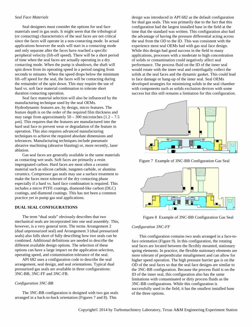
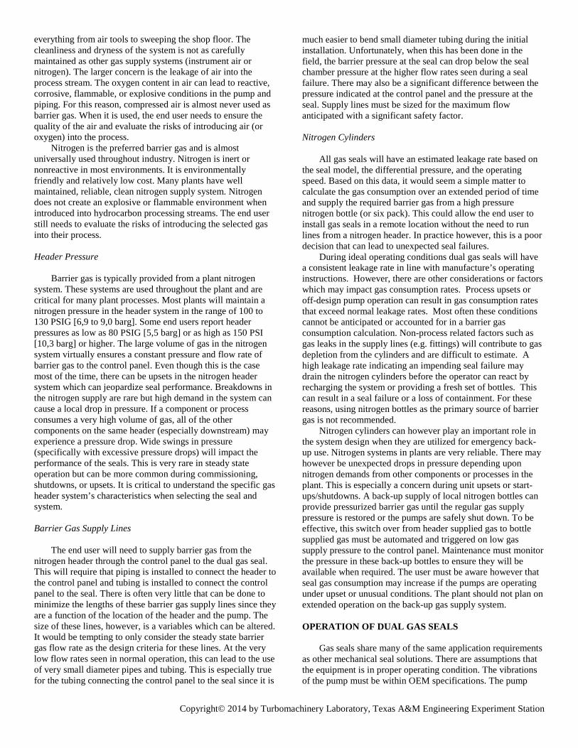
Configuration 3NC-BB
The 3NC-BB configuration is designed with two gas seals arranged in a back-to-back orientation (Figures 7 and 8). This
design was introduced in API 682 as the default configuration for dual gas seals. This was primarily due to the fact that this configuration had the largest installed base in the field at the time that the standard was written. This configuration also had the advantage of having the pressure differential acting across the seal from the OD to the ID. This was consistent with the experience most seal OEMs had with gas seal face design. While this design had good success in the field in many applications, processes with a moderate to high concentration of solids or contamination could negatively affect seal performance. The process fluid on the ID of the inner seal would rotate with the inner seal and centrifugally collect the solids at the seal faces and the dynamic gasket. This could lead to face damage or hang-up of the inner seal. Seal OEMs developed strategies for minimizing solids in the seal chamber with components such as solids exclusion devices with some success but this still remains a limitation for this configuration.
Figure 7 Example of 3NC-BB Configuration Gas Seal
Figure 8 Example of 3NC-BB Configuration Gas Seal
Configuration 3NC-FF
This configuration contains two seals arranged in a face-to-face orientation (Figure 9). In this configuration, the rotating seal faces are located between the flexibly mounted, stationary spring elements. In practice, the flexible stationary elements are more tolerant of perpendicular misalignment and can allow for higher speed operation. The high pressure barrier gas is on the OD of the seal faces so that the seal face designs are similar to the 3NC-BB configuration. Because the process fluid is on the ID of the inner seal, this configuration also has the same limitations with contaminated or dirty process fluids as the 3NC-BB configurations. While this configuration is successfully used in the field, it has the smallest installed base of the three options.

Copyright© 2014 by Turbomachinery Laboratory, Texas A&M Engineering Experiment Station
Figure 9 Example of 3NC-FF Configuration Gas Seal
Configuration 3NC-FB
The 3NC-FB configuration contains two gas seals arranged in a face-to-back orientation (see Figures 10 and 11). This orientation is often referred to as a series or tandem configuration. This design has the unique requirement that the high pressure barrier gas is on the ID of the inner seal. This requires that the hydrodynamic face features are on the ID of the seal face and the barrier gas migrates radially outward. This orientation has the process fluid on the OD of the inner seal which can allow solids and contamination to be expelled radially away from the seal with the rotation of fluid in the seal chamber. Pressurizing the inner seal from the ID places the faces into tension which may limit its use in high pressure applications. The outer seal is often a conventional OD pressurized design. This configuration can be designed with either rotating or stationary flexibly mounted seals.
Figure 10 Example of 3NC-FB Configuration Gas Seal
Figure 11 Example of 3NC-FB Configuration Gas Seal
Pusher vs Bellows
The most common categorization of mechanical seals,
including gas seals, concerns the design of the basic flexible components – pusher seals and bellows seals. A pusher seal by definition is a “seal that incorporates a dynamic secondary seal to allow axial movement of the flexible element” (API 682). A bellows seal “uses a flexible metal bellows to provide sealing and seal loading” (API 682). While both of these seal types are widely used in industry, the unique characteristics of each can make the selection of one design more beneficial for a specific application. This is also true in gas seal designs.
Pusher
Pusher seals are the most commonly used seal type for both liquid and gas seals in general industry. The design of the components is relatively straightforward and this allows for easy customization for the specific application requirements. The seal faces themselves are generally monolithic components which can allow for the lower stresses on the seal face and more stable face flatness over a wide range of operating conditions. The flexible seal face is driven by drive pins or keys. This face is sealed against the seal sleeve (or other mating component) with a dynamic gasket such as an o-ring. The drive pins and gasket provide dampening of the seal face in operation and helps prevent vibration or undampened excitation. The metallic components of the seal can be constructed of virtually any metallic material. Finally, pusher type seals can be designed to handle extremely high pressure differentials.
There are negative aspects for some of these same design features. Since the flexible seal face must slide on the balance shoulder of the mating component, a build-up of solids or debris can cause hang-up of the gasket. As discussed earlier, the face loading on gas seal faces is significantly less than liquid seals so the potential for hang-up is greater. The use of gaskets also means that the application window for the seal may be determined by the chemical or temperature limitations of the gaskets themselves. Most gas seals use elastomer o-rings although some designs use spring energized, polymeric gaskets to expand the operating window.
Bellows
Bellows seals replace the dynamic gasket and spring component of the pusher seal with a flexible bellows element. In most medium or high duty seal applications, the bellow will be an edge welded, metal bellows design. This design is used for both liquid and gas seals as well as specialty sealing applications such as steam turbine seals. The obvious advantage to eliminating the dynamic gasket is removing the sliding interface between the dynamic gasket and mating surface. All axial motion in the seals is taken up by the flexing or deformation of the bellows element. This minimizes the chance that the seal will hang-up in dirty services. Eliminating the elastomers (in some designs) also removes the temperature limitations and can allow the seal to be installed in high temperature applications.
Bellows gas seals however have some inherent limitations which need to be considered. The connection of the bellows diaphragms to the seal face is accomplished through the use of a shrink fit element or some multi-component face holder. These designs, especially the shrink fit, need to be carefully

Copyright© 2014 by Turbomachinery Laboratory, Texas A&M Engineering Experiment Station
engineered to ensure acceptable face flatness for the range of operating conditions. The seal face (and holder) and bellows are essentially a spring mass system with an associated critical frequency. This design therefore may require dampening devices to reduce vibrations and prevent fatigue failures in the bellows. Welded metal bellows also tend to have a higher spring rate than pusher seals designs which will require a more careful seal setting (axial location) or limit the allowable shaft motion in service. Bellows in general will have a lower maximum pressure rating than pusher seals and will have a limited selection of metallic materials for the bellows diaphragms. These limitations though have been largely overcome by careful design and application selection. Dual gas bellows seals have a large, successful installed base and in some services is the preferred (or only) option. Considerations When Applying Dual Gas Seals
Most centrifugal pump applications can be successfully sealed with a variety of seal types or arrangements. There may however be specific requirements or consequences associated with a particular solution. Knowing these can help the user to select the most appropriate technology for their application. It is helpful to compare the relative strengths and weakness between dual liquid seals and dual gas seals when making this selection.
Barrier Leakage into the Process
In dual pressurized liquid seals, the inner seal will leak small amounts of barrier fluid into the process. For certain applications, such as high purity or finished products, the barrier fluid may be viewed as a contaminant and not allowed into the process. In other cases, the barrier fluid may react with fluid in the pump or have an unacceptable impact on downstream processes in the plant. The selection of a barrier fluid is one of the most critical aspects of dual liquid seal installations.
Dual gas seals use an inert gas for pressurizing the seals. This barrier gas will enter the process fluids in small quantities. While the selection and purity of the gas is a consideration, most industrial applications use clean dry nitrogen from the plant’s existing nitrogen system. The barrier gas will not react with most chemicals and can be easily removed from the most products without affecting downstream processes.
Barrier Leakage to Atmosphere
Barrier fluid will not only leak into the pump but will also leak on the atmospheric side of the seal. Liquid barrier fluids will leak past the outer seal and flow into a drain or be collected in the pump bracket or on the baseplate. While this leakage rate is extremely low, an end user may view any liquid phase leakage as a housekeeping issue. Large amounts of barrier fluid leakage associated with a seal failure will increase this concern. Leakage of a nitrogen barrier gas to the environment is viewed as non-hazardous and does not create any housekeeping concerns. If these dual gas seals are used are in enclosed areas however, the user should consider oxygen displacement.
Simpler Seal Support System Design
The barrier fluid and its support system in dual pressurized liquid seals is a critical part of the sealing system. There must be a significant amount of liquid available to serve as a reservoir to compensate for seal leakage. This volume also allows for an adequate retention time in the reservoir for cooling and a larger volume reduces the rate of degradation of the fluid. The barrier fluid must be circulated throughout the system by the seal or by an external circulation pump. The entire system must be pressurized from an external utility or from additional system components. While dual pressurized liquid seals are often considered the most advanced solution available, the hardware requirements for the piping plan are a critical part of the seal’s reliability and require careful selection and operation.
Dual pressurized gas seals operate on a barrier gas supplied from an external gas system. This is most often an existing nitrogen header in the plant. The difficulty of providing this gas to the seal depends upon the distance between the supply header and the pump (as well as any challenges with installing the required piping between the two.) A barrier gas control panel installed at the pump ensures the gas is filtered, regulated to the correct pressure, and monitored for flow and pressure. Since the gas seals do not generate significant heat, no circulation is needed and no additional cooling auxiliaries (e.g. seal cooler) are required. In some cases, the dual gas seal may require a simpler support system than comparable dual liquid systems.
In most cases, the gas supply header pressure will be high enough to be used as a barrier gas. In most plants, the header pressure is maintained from 100 to 130 PSIG [6,9 to 9,0 barg]. In normal applications, the barrier gas pressure in the seals must be between 25 to 50 PSI [1,7 to 3.4 bar] greater than the pressure in the seal chamber. If the supply pressure cannot meet this requirement, the barrier gas pressure must be increased to the required pressure. This is often done with an external pressure booster or pressure amplifier. While this can successfully increase the barrier gas pressure, the mechanical reliability of the booster will often define the reliability of the entire sealing system.
Automatic Barrier Make-up
All seals leak at some rate. In dual seal systems, the barrier fluid will leak across both the inner and outer seal. In liquid barrier fluid systems, additional make-up fluid must be periodically added to the reservoir to compensate for this loss. This is often done manually by pumping fluid into the barrier system under pressure. Instrumentation or visual observations will alert the operator that barrier fluid needs to be added. Automatic barrier fluid refill systems are available but are not in common use.
In dual gas seal applications, the barrier gas is continually supplied to the seal through the control panel to compensate for the normal seal leakage. There is no operator intervention required to refill the system. The performance of the make-up system (pressure and flow rate) is however tied to the reliability of the control panel and availability of gas from the nitrogen header.

Copyright© 2014 by Turbomachinery Laboratory, Texas A&M Engineering Experiment Station
Maintenance Requirements
Barrier fluid systems may require maintenance to maintain peak performance. Depending upon the application, the barrier fluid may need to be periodically changed and replenished with new fluid. Some systems may require that dedicated seal coolers are flushed to minimize fouling. In general, however, a properly designed and operated liquid barrier fluid system does not require significant maintenance (other than barrier fluid make-up).
Most dual gas seals are also designed for long operating cycles without significant maintenance. The only item which does require routine monitoring and maintenance is the coalescing filter. This will require blowing down the filter or replacing the coalescing element. The frequency will depend upon the size of the filter and the cleanliness of the gas supply. If a pressure booster or amplifier is used on the gas supply system, the monitoring and maintenance requirements will be dictated by the IOM for this component. It is important to recognize that these components do require routine maintenance and a failure to follow the maintenance instructions can lead to loss of barrier gas pressure and seal failure.
External Utilities
External utilities refer to the supply of any external fluid or energy source to the sealing system. The most commonly used utilities in a typical plant environment are electricity, cooling water, compressed air, nitrogen, or steam. The types of utilities required for a sealing system depend very heavily on the actual piping plan and auxiliary selection and less on the selection of a liquid or gas seal.
In dual liquid seals, the barrier fluid requires pressurization and cooling. Pressurization may be supplied by an external gas (nitrogen header) or an autonomous bladder accumulator / piston transmitter. Cooling may be provided by cooling water or an air-cooled system. Air-cooled systems may rely on natural convection or use an electrically driven fan. Occasionally, a user may request a pneumatically or hydraulically drive fan on an air cooler. Barrier fluid systems may then be designed so they require external utilities (typically pressurized gas and cooling water) or do not require external utilities.
Dual gas seals will only require a constant source of pressurized barrier gas. This must be provided from a reliable gas supply system and not by a local bottle (or “six pack’’). Cooling water or other utilities are not required.
Failure Indication
Barrier fluid leakage is considered one of the most direct indicators of seal performance. In dual liquid seal applications, barrier fluid leakage is monitored only indirectly and often only qualitatively. The actual mechanism for the monitoring depends upon the piping plan selection. Plan 53A system uses level in the (site glass, low level switch, and/or level transmitter.) Plan 53B uses a pressure (indicator, low pressure switch, or pressure transmitter). Plan 53C uses the piston position in the piston
transmitter. While there is a possibility to obtain accurate performance data, most end users use leak rate descriptions like “had to fill the reservoir once per shift”. Most dual seal failures are determined by operator’s tolerance for refilling the barrier fluid system. In some cases, process contamination or visible external seal leakage may be the determining factor.
Dual gas seals utilize most often use gas control panel which is equipped with barrier gas pressure and flow instrumentation. As a result, barrier gas flow rate and pressure can be directly and accurately monitored. An increasing gas flow rate trend may provide advanced warning to potential seal failure. The user should be aware that many visual flow meters are calibrated for a specific pressure (often for an atmospheric outlet pressure). Correction factors for converting the observed reading into the actual volumetric flow rate can be found on the gas control panel of the panel IOM.
Some end users may use a novel monitoring technique on dual gas seals. The non-contacting nature of dual gas seal faces means there is no seal face generated heat. The seal gland temperature is defined by pump temperature and heat losses to the atmosphere. If there is a rapid change in gland temperature which cannot be attributed to process conditions, there is likely significant contact between the seal faces indicating an impending failure. Warning: this is not an endorsement for operators to stick their hand near an operating pump. Proper measurement techniques and safety practices must be followed.
Run After Failure
Surprisingly, some end user select gas seals not only based on how they run but also on how they fail. When a dual liquid seal fails, the barrier fluid will leak into the pump or out to the atmospheric side of the seal. This may create an unacceptable leakage into the process or loss of barrier fluid into the drain or pump bracket. It can also cause a loss of barrier fluid pressure resulting in a loss of containment of the process fluid. At a minimum, it will represent unacceptable barrier fluid make-up activities for the operator.
Dual gas seals often fail with an increase in barrier gas leakage. High gas leakage into the pump may be acceptable depending upon the pump and process tolerance of gas. Leakage of barrier gas (nitrogen) into the air is generally not a concern for most applications. At moderate leakage rates, the supply of nitrogen barrier gas can be supported for an indefinite period of time. Some end users will operate a failed (or failing) dual gas seal long after its performance has degraded. This may allow them to operate until it is more convenient to shut down the equipment and replace the seal. This practice however comes with some severe caveats and is not generally a supported operating strategy from any seal OEM. First, the barrier control panel and interconnecting piping are designed to operate at the low to moderate flow rates seen in normal service. At very high flow rates, there can be a significant pressure drop through the system which results in lower than expected pressure in the gas seal. This can cause the barrier pressure to drop below the seal chamber pressure resulting in process leakage to atmosphere. The second risk is that continued operation with damaged seal faces increases the opportunity for rapid and catastrophic breakage of the faces. This would result in a loss of containment. Although many

Copyright© 2014 by Turbomachinery Laboratory, Texas A&M Engineering Experiment Station
operators have used this technique successfully in the past, it is not recommended.
Oxygen Displacement
Dual gas seal will leak barrier gas (nitrogen). Since there will be continual barrier gas leakage into the surrounding environment, the location of the equipment and impact of the leakage must be considered. Most process environments are open to a free circulation of air around the equipment. This prevents the build-up of potentially harmful gases and vapors. Some equipment however may be installed in an enclosed space or in the interior of a building. Excessive barrier gas leakage or sustained operation in areas with little or no ventilation may result in oxygen displacement and represent a safety hazard. This becomes more of a concern as the number of gas seals in the enclosure increases. Safety precautions and warning signs should be considered in poorly ventilated areas.
Figure 12 Warning Sign for Oxygen Deficient Environment High Temperature Applications
High temperature applications present a number of challenges to dual gas seals. In pusher type gas seals, the elastomer selection is critical to the proper operation of the seals. Dynamic gaskets exposed to high temperatures may experience excessive growth due to high thermal expansion. This can result in an over-compressed dynamic gasket and increased gasket drag. The increased drag can impact the seal face’s ability to maintain the proper gas film thickness and result in face contact or high face leakage. Since gas seals typically use a lower spring load to facilitate face separation, the spring force is less likely to overcome this drag resulting in a face hang-up. High temperature bellows gas seals are available which would not be susceptible to this condition.
High temperature applications will also have an impact on equipment stability. Depending on pump design, thermal expansion of equipment may result in misalignment of critical seal interface dimensions. This misalignment can result in run out conditions beyond the seal’s capability. In addition, pumps in hot applications may experience significant shaft growth during the warm-up procedure due to uneven heating between the shaft and pump casing. If the seals are started in an overcompressed state, the seals will have higher than normal face loading. Following proper warm-up procedures can minimize these risks.
Vertical Pumps in Hot or Dirty Services
High temperature vertical pumps may present a unique opportunity for dual gas seals. Barrier gas which leaks past the inner seal will collect under the seal. In high temperature applications, this will provide an isolating blanket between the hot process in the pump and the seal components (Figure 13). In dirty services, this isolating blanket can also minimize solids or contamination in the process from reaching the seal. In both cases, the clean dry environment directly under the seal can improve seal performance. If the user is relying on this mechanism, the pump should be provided with a dead ended seal chamber (Plan 02) and the venting location for priming the pump should be below the bottom of the gas seal.
Figure 13 Vertical Pump with Dual Gas Seal There is a specific limitation to using this solution on
vertical pumps. Many vertical pumps have a product lubricated steady bearing (sleeve type) under the seal chamber. This bearing requires product lubrication and can, in some cases, require a flow through the bearing to provide cooling and lubrication. The flow is generated by circulation of the process with a Plan 13 back to pump suction. If a Plan 02 is used, there will be no flow. Even more concerning, the seal chamber and potentially the bearing will be filled with accumulated gas leakage resulting in a dry bearing condition. To use this approach in these pumps, there must be a pressure balance line between the bearing and seal chamber which bleeds back to suction. As an alternative, a Plan 13 could be installed in the seal chamber with the return line located vertically lower than the bottom of the gas seal.

Copyright© 2014 by Turbomachinery Laboratory, Texas A&M Engineering Experiment Station
Speed Considerations
Rotational speed must be considered when applying dual pump gas seals. Hydrodynamic face features require rotational velocity to generate lift. This is not normally a concern for synchronous speed applications but it can be a concern for low speed or variable speed operation. Pumps with variable speed drives should be evaluated at all of the expected RPMs and operating conditions. Operation below the minimum lift-off speed for the seal will result in insufficient lift and seal face contact. This will cause damage to the seal faces and impact seal reliability. Equipment that spins slowly during standby conditions (such as a turbine driven pump) or a pump with a soft start motor drive that slowly ramps up equipment RPM to full speed may require special attention. Gas seals for these applications may require a modified face feature that creates higher lift in low RPM conditions. This is also a common consideration in equipment such as high power mixer/agitator drives where shaft RPM is significantly lower than motor input speeds. Although RPM is a common method of describing equipment speed, the peripheral speed is actually the critical parameter so shaft size must also be considered. Larger shaft sizes will require less RPM to achieve the same peripheral speed of smaller shaft sizes. Therefore, gas seals for larger shaft size equipment may require less RPM than smaller shaft size equipment for proper gas seal operation.
Process Contamination (Solids)
Process streams containing contamination can be troublesome for any sealing application. This is especially true for gas seals where the accumulation of solids can cause drag or hang-up of the dynamic gasket. This will result in erratic seal performance or high leakage. Some seal OEMs have developed devices which can help expel solids from the seal of seal chamber and provide a cleaner environment at the seal. These have had mixed results in actual applications. Processes which will plate out or otherwise collect on the seal surfaces are also a concern.
Even though dual gas seals are intended to operate with a barrier gas pressure greater than the seal chamber pressure, there will be some upset conditions where this is not the case. Unexpected pressure spikes in the pump may increase the seal chamber pressure. An unexpected loss of barrier pressure may occur if there decrease in pressure in the gas supply header. The coalescing filter may become plugged over time. An operator may even accidentally close barrier gas supply line into the panel. Even though these conditions may be temporary, process fluids can get between the seal faces. Dirty process fluids may carry particles or debris between the seal faces. This may cause grooving or abrasive wear on the face. It may also collect and pack up the hydrodynamic micro features on the face. This will impact the seals ability to create lift and eventually cause the seal to fail. Different hydrodynamic face patters have different tolerance to dirt and contaminations. Face patterns with smooth features such as waves will be less susceptible to accumulation of debris in the hydrodynamic features. End user must ensure that the gas barrier pressure is maintained at the correct pressure and prevent reverse pressurization of the inner seal.
Process Contamination (Crystallization) Although a process stream may be free of solids it may still
be possible that barrier gas itself may help create solids in the process. Barrier gas leakage into the process may result in crystallization of the product on the process side of the seal faces. This occurs as the barrier gas exits the faces and enters the process fluid in the seal chamber. The flow of dry nitrogen into the fluid may cause crystallization or dehydration resulting in the formation of solids. The crystallization will continue to build over time and can eventually cause seal hang-up or otherwise impact seal performance. This is a common failure mode in process fluids like sodium hydroxide. Process which readily form crystals or solids when exposed to dry nitrogen are better suited for dual liquid seals or a single seal with a water quench.
Equipment Rotation
The operator must pay close attention to the direction of the shaft rotation. It is generally a good practice to establish the direction of rotation of an electrical motor prior to installing the coupling between the pump and driver. This will prevent accidental reverse rotation of the pump. While this is considered an important factor for proper operation of the pump, it may also be a critical factor for the performance of a gas seal.
Some seal faces are designed so that the hydrodynamic features only create lift when the seal faces are rotated in one direction. These are called unidirectional faces patterns. When a unidirectional face is rotated in the opposite direction, it may actually pump the gas film out of the faces resulting in very high face contact. This will result in damage to both the hydrodynamic features as well as the other sealing surfaces on the face. Even short duration operation with the wrong rotation can cause significant damage to unidirectional seal faces. During initial commissioning of equipment, proper rotation of shaft must be verified to ensure the rotation is correct. Most seal OEMs can also provide bidirectional face features which can operate equally well in either direction. Equipment Considerations
Most centrifugal pumps require a method of providing a seal or sealing device at the interface between the rotating shaft and the stationary pump housing or casing. Historically, rings of compression packing were installed into a radially narrow cavity and compressed to provide a seal. This cavity has been termed a stuffing box or packing box and is still in use today in some pump designs. As mechanical seals were introduced, the size of this cavity was increased to hold the larger, more robust modern seal designs. The larger cavity size also improved the environment around the seal resulting in more reliable seal performance. This larger cavity is termed as the seal chamber or seal cavity.
It is not surprising that stuffing boxes and seal chambers come in a wide variety of sizes and configurations since there is such a wide variety of pumps and rotating equipment in the field. There have been some efforts to help standardize the size and mechanical seal interface of pumps both through API 682

Copyright© 2014 by Turbomachinery Laboratory, Texas A&M Engineering Experiment Station
and ASME B73. Fortunately, most pump OEMs have migrated towards supplying seal chambers as a standard (or at least as an option). Even with these efforts, the equipment constraints around the stuffing box or seal chamber will play a part in the selection and design of a mechanical seal.
Gas seals tend to be radially larger than similar sized liquid seals. This is primarily due to the wider seal faces required for creating hydrodynamic lift. Many gas seal models are design specifically for use in seal chambers. The larger radial space requirements would not allow them to be installed in stuffing box or smaller sealing cavities. There is however a large installed base of stuffing boxes in the smaller ASME B73 style pumps. Seal OEMs have designed special seal configurations where the seal is entirely outside of the stuffing box (Figure 9). While this allows for greater radial space, the tight axial restrictions between the stuffing box and bearing housing can create design compromises in the seal. Even though gas seal models are available for stuffing boxes, users are encouraged to upgrade their pumps to seal chamber design back plates since this gives options for more robust seal designs.
Equipment Condition
The condition of the centrifugal pump will impact the performance of any mechanical seal. High radial run outs due to shaft deflection will create unstable tracking of the seal faces. High perpendicular run out between the shaft and seal chamber face can cause uneven face loading and axial wear on the dynamic gasket and drive pins. High overall vibrations can impact the seal’s ability to maintain a proper fluid film resulting in erratic leakage rates or face damage. Worn bearings or improper bearing fits may contribute to excessive shaft motion. Continuous shaft shuttling can also cause drive pin and gasket wear. Any motion (other than pure rotation) of the seal or the pump shaft will not be beneficial to the reliability of a mechanical seal.
Gas seals can be even more sensitive to equipment condition than contacting wet seals. The lack of a lubricating fluid means that any face contact during operation will result in face wear. Since the faces are “floating” on a fluid film, instabilities or run outs in the equipment can result in changes in the film thickness and resulting leakage rate. The gas film between the seal faces is less effective at dampening the vibrations in the seal components than a comparable liquid seal. End users should maintain all of their centrifugal pumps to factory specification regardless of the seal type. Dual gas seals however can often benefit the most from this practice.
Barrier Gas Leakage and Pump Performance
One of the concerns with using dual gas seals is the potential impact the of the inner seal leakage on pump performance in operation. Barrier gas will enter the seal chamber and migrate into the pump. Depending upon the pump design, the gas may enter from either the front or back of the impeller. Due to spinning of the impeller and fluid in the casing, the barrier gas can migrate towards the eye of the impeller. Over time, an increase in the size of this bubble can impact pump performance or, in extreme cases, cause vapor lock or a loss of prime. At least these are the fears that
operators have had since the introduction of gas seals. Field experience and lab testing (Turley, 2000) has shown
that this condition is unlikely in an operating pump and that normal barrier gas leakage will not have a large impact on pump performance. Lab tests have shown that small volume pumps operating at low flow rates may be affected in the lab. End users have also seen this occur in some low pressure, low flow field installations. Pumps operating with higher flow rates however have not seen a significant impact on the performance of these pumps in the field.
The effect of gas leakage on pumps in standby conditions can be different. If the pump is allowed to sit statically with no flow through the pump, large volumes of barrier gas can accumulate in the pump casing and piping which can dramatically impact the performance of the pump (see Operation of Dual Gas Seal – Standby below). PIPING PLANS
Piping plans are formalized strategies for improving the environment in the seal chamber, providing alternative sealing fluids, and monitoring seal performance. The majority of popular piping plans are defined in API 682. This standard provides not only a description of the function of the plan, but also specifications for components and instrumentation for the installation.
Plan 74
Piping Plan 74 is a pressurized barrier gas control system for Arrangement 3, dual non-contacting seals (Figure 14). The purpose of the plan is to provide a clean, dry barrier gas at pressures typically 25 to 50 PSIG [1,7 to 3,4 bar] higher than the process pressure in the seal chamber. The plan covers not only the interface of barrier gas within the seal but also describes specific requirements for the barrier gas control panel.
Figure 14 API 682 Piping Plan 74
Barrier Gas Control Panel
The actual design of the barrier gas control panel is not defined in API 682 or any other industrial standard. This has resulted in a wide variety of designs, functions, and features on

Copyright© 2014 by Turbomachinery Laboratory, Texas A&M Engineering Experiment Station
panels used throughout industry. This is driven equally by customer’s specifications, seal OEM’s preferences, and application requirements. API 682 does however describe some of the basic components that should be included on a control panel. The description below highlights the requirements from API 682 Fourth Edition (Figure 15).
Figure 15 Details of Piping Plan 74 – API 682 Fourth Edition
Gas enters the panel at a block valve. This valve will allow
the operator to block the barrier gas from the panel for maintenance or seal repair. The barrier gas flows through a coalescing filter to remove small particulates and water from the supply stream. The supply pressure from the nitrogen header is regulated down to the pressure required by the seal through a pressure reducing regulator. The flow through the panel is monitored with an indicating flow transmitter. The pressure of the barrier gas exiting the panel is monitored with an indicating pressure transmitter. The use of a transmitter for pressure and flow allows for both local and remote monitoring/alarming as well as trending the seal and gas supply system performance. The last component on the panel is a check valve which will prevent process fluid from entering the control panel if barrier gas pressure is lost.
In earlier editions of API 682, a flow meter and high flow switch were used instead of the flow transmitter (Figure 16). For monitoring pressure, a pressure indicator and low pressure switch was used instead of the pressure transmitter. This configuration can still be supplied and actually represents the majority of barrier gas control panels installed in the field.
Figure 16 Details of Piping Plan 74 – API 682 Third Edition
There are some other practical recommendations to
consider when installing the control panel into the plant. The control panel must be located at a height suitable for the operator to monitor and manipulate the panel’s components. The panel must be located on a substantial stand or mounting location to prevent damage to the panel or the connecting piping and tubing. The control panel must also be clearly marked with the pump or equipment number to ensure that the
operator is controlling or monitoring the correct pump. Finally, one gas control panel should be used per seal to allow for more accurate monitoring and to prevent the failure of one seal from affecting the performance of other seals. Proximity of Barrier Gas Control Panel to Seal
While the location of the control panel relative to the pump and seal may seem like an afterthought, it can play an important role in the performance of the seal as well as improve the operator experience with the equipment.
The control panel provides the functions of control, conditioning, and monitoring the barrier gas but the piping plan installation must also include the piping or tubing to connect the control panel to the actual mechanical seal. Since this is a pressurized gas system, there are no requirements for venting or draining the tubing. The flow rate under ideal conditions is relatively low so pressure drops in the supply line will be low. These factors would lead an end user to assume that tubing runs and panel location are not important.
Even though normal barrier flow rates are low, operating the pump in upset conditions may result in higher flow rates. As the seal begins to fail, the flow rate will continue to rise until the flow is unacceptable to the end user. This condition may require the use of larger diameter supply tubing and shorter, more efficient tubing runs (see Barrier Gas Supply Lines below).
Another benefit for locating the control panel near the pump is to create a natural relationship between the control panel and the pump. Operators will need to ensure that the block valve supplying gas to the panel is opened and that the barrier pressure is correctly set prior to starting the pump. Operators will also make rounds through the plant to check on the pumps and panels. These activities are more convenient if the panel is physically located near the pump. Even with this relationship, the control panels must be clearly marked with the pump or equipment number. CONSIDERATIONS FOR GAS SUPPLY SYSTEMS
The reliability of a dual gas seal is completely tied to the reliability of the barrier gas supply system. This includes the selection of the gas, the source of the gas, the delivery system or piping, and the contingencies to handle upsets in the system. All of these aspects need to be considered when evaluating the barrier gas supply system.
Barrier Gas Selection
Almost any gas could theoretically be used as a barrier gas. The actual list of gases used in industry though is very small. Barrier gas must be extremely clean and dry for optimal seal performance. The gas must be readily available and have a dependable supply system. It must have low cost since there will be continued usage over time. It must be environmentally friendly since there will be leakage to atmosphere. It must also be compatible with the process.
An end user might be tempted to use plant air as a barrier gas but in most cases this would not be recommended. In many plants, the plant air system is a general use source of gas for
Copyright© 2014 by Turbomachinery Laboratory, Texas A&M Engineering Experiment Station
everything from air tools to sweeping the shop floor. The cleanliness and dryness of the system is not as carefully maintained as other gas supply systems (instrument air or nitrogen). The larger concern is the leakage of air into the process stream. The oxygen content in air can lead to reactive, corrosive, flammable, or explosive conditions in the pump and piping. For this reason, compressed air is almost never used as barrier gas. When it is used, the end user needs to ensure the quality of the air and evaluate the risks of introducing air (or oxygen) into the process.
Nitrogen is the preferred barrier gas and is almost universally used throughout industry. Nitrogen is inert or nonreactive in most environments. It is environmentally friendly and relatively low cost. Many plants have well maintained, reliable, clean nitrogen supply system. Nitrogen does not create an explosive or flammable environment when introduced into hydrocarbon processing streams. The end user still needs to evaluate the risks of introducing the selected gas into their process.
Header Pressure
Barrier gas is typically provided from a plant nitrogen system. These systems are used throughout the plant and are critical for many plant processes. Most plants will maintain a nitrogen pressure in the header system in the range of 100 to 130 PSIG [6,9 to 9,0 barg]. Some end users report header pressures as low as 80 PSIG [5,5 barg] or as high as 150 PSI [10,3 barg] or higher. The large volume of gas in the nitrogen system virtually ensures a constant pressure and flow rate of barrier gas to the control panel. Even though this is the case most of the time, there can be upsets in the nitrogen header system which can jeopardize seal performance. Breakdowns in the nitrogen supply are rare but high demand in the system can cause a local drop in pressure. If a component or process consumes a very high volume of gas, all of the other components on the same header (especially downstream) may experience a pressure drop. Wide swings in pressure (specifically with excessive pressure drops) will impact the performance of the seals. This is very rare in steady state operation but can be more common during commissioning, shutdowns, or upsets. It is critical to understand the specific gas header system’s characteristics when selecting the seal and system.
Barrier Gas Supply Lines
The end user will need to supply barrier gas from the nitrogen header through the control panel to the dual gas seal. This will require that piping is installed to connect the header to the control panel and tubing is installed to connect the control panel to the seal. There is often very little that can be done to minimize the lengths of these barrier gas supply lines since they are a function of the location of the header and the pump. The size of these lines, however, is a variables which can be altered. It would be tempting to only consider the steady state barrier gas flow rate as the design criteria for these lines. At the very low flow rates seen in normal operation, this can lead to the use of very small diameter pipes and tubing. This is especially true for the tubing connecting the control panel to the seal since it is
much easier to bend small diameter tubing during the initial installation. Unfortunately, when this has been done in the field, the barrier pressure at the seal can drop below the seal chamber pressure at the higher flow rates seen during a seal failure. There may also be a significant difference between the pressure indicated at the control panel and the pressure at the seal. Supply lines must be sized for the maximum flow anticipated with a significant safety factor.
Nitrogen Cylinders
All gas seals will have an estimated leakage rate based on the seal model, the differential pressure, and the operating speed. Based on this data, it would seem a simple matter to calculate the gas consumption over an extended period of time and supply the required barrier gas from a high pressure nitrogen bottle (or six pack). This could allow the end user to install gas seals in a remote location without the need to run lines from a nitrogen header. In practice however, this is a poor decision that can lead to unexpected seal failures.
During ideal operating conditions dual gas seals will have a consistent leakage rate in line with manufacture’s operating instructions. However, there are other considerations or factors which may impact gas consumption rates. Process upsets or off-design pump operation can result in gas consumption rates that exceed normal leakage rates. Most often these conditions cannot be anticipated or accounted for in a barrier gas consumption calculation. Non-process related factors such as gas leaks in the supply lines (e.g. fittings) will contribute to gas depletion from the cylinders and are difficult to estimate. A high leakage rate indicating an impending seal failure may drain the nitrogen cylinders before the operator can react by recharging the system or providing a fresh set of bottles. This can result in a seal failure or a loss of containment. For these reasons, using nitrogen bottles as the primary source of barrier gas is not recommended.
Nitrogen cylinders can however play an important role in the system design when they are utilized for emergency back-up use. Nitrogen systems in plants are very reliable. There may however be unexpected drops in pressure depending upon nitrogen demands from other components or processes in the plant. This is especially a concern during unit upsets or start-ups/shutdowns. A back-up supply of local nitrogen bottles can provide pressurized barrier gas until the regular gas supply pressure is restored or the pumps are safely shut down. To be effective, this switch over from header supplied gas to bottle supplied gas must be automated and triggered on low gas supply pressure to the control panel. Maintenance must monitor the pressure in these back-up bottles to ensure they will be available when required. The user must be aware however that seal gas consumption may increase if the pumps are operating under upset or unusual conditions. The plant should not plan on extended operation on the back-up gas supply system. OPERATION OF DUAL GAS SEALS
Gas seals share many of the same application requirements as other mechanical seal solutions. There are assumptions that the equipment is in proper operating condition. The vibrations of the pump must be within OEM specifications. The pump

Copyright© 2014 by Turbomachinery Laboratory, Texas A&M Engineering Experiment Station
should be operating near the BEP on the curve. The alignment of the shaft to the seal chamber must be within API 682 or ASME B73 specifications. Most of the factors which would negatively impact the performance of a liquid seal will also negatively impact a dual gas seal.
There are other factors however which are unique to gas seals or conditions where dual gas seals will be more sensitive than comparable liquid seals. The end user needs to evaluate their operating procedures and minimize or eliminate these conditions to maximize seal performance.
Commissioning
Dual gas seals must be pressurized prior to inventorying or filling the pump with process fluid. This is a good practice for all Arrangement 3 seals, liquid or gas, but it is critical for gas seals. Most Arrangement 3 seals are designed to keep the seal faces from hydraulically “blowing open” when reverse pressurized. This however does not prevent process fluid from migrating between the inner seal faces. Liquid seals tend to be tolerant of this condition since they are designed to operate on a liquid film. Gas seals, however are designed to operate on a gas film and the presence of process leakage may negatively affect the seal. If the process fluid is a clean, low viscosity, lubricating fluid, the impact may be negligible. If the process is a dirty, viscous, solidifying, or polymerizing fluid, the impact may be significant.
Operation
Considerations for the operation of a dual gas seal under steady state conditions are relatively simple. If the seal and gas system has been properly designed, installed, and commissioned, the gas seal will operate with little or no operator intervention. The operator does need to ensure that the actual operating pressures for the pump are same as the figures used to set up the systems. Any changes in operating conditions away from the original figures should prompt the user to review the pressure settings for the system.
Operators will often use the flow meter reading to monitor seal health. It is important to realize that, even under steady state conditions, there can be some variations or fluctuations in the flow meter reading. This is especially true if there are changes in the operating conditions of the pump.
Standby
During standby, a centrifugal pump is exposed to the process fluid under pressure and often at pumping temperature. In most cases, the pump is in a condition where it may be started without significant operator intervention. This may be a temporary standby condition (e.g. start-up or batch operation) or a long term standby strategy (e.g. hot spare). In either case, the seal will be exposed to process fluid under pressure and therefore must have the barrier gas system and the seals pressurized. The barrier pressure should be set for operational conditions since the pump may be started at any time.
One of the side effects of dual gas seals in standby is the accumulation of barrier gas in the pump and piping system. Most dual gas seals are designed so that faces are in contact
during static conditions. This results in a lower-than-normal barrier gas leakage rate into the pump. There will however be some gas leakage which flows into the seal chamber and pump casing. If the pump is on extended standby, this accumulated gas can fill the pump casing and impact the pump’s ability to properly prime when put into service. In extended standby conditions, the barrier gas can also fill portions of the piping around the pump. This is highly dependent on the design of the piping and location of valves. Since a standby pump is often connected in parallel to an operating pump, gas accumulation in the standby pump’s suction line may migrate to the operating pump and affect its performance. To ensure a proper pump start-up and minimize the impact of a gas slug on downstream processes, the end user should vent the pump after extended down time or standby conditions. Some end users have also developed more elaborate strategies for minimizing the accumulation of gas or automatically venting gas from the pump and piping.
Slow Roll
In most cases, when a pump is in standby, the shaft is stationary. That is not always the case and the reasons for rotation may be intentional or unintentional. Regardless of the reason, the user needs to understand the potential for this condition and ensure that the seal design is suitable for the application.
In hot services, some end users will place a pump into a slow roll condition. This may be done for reasons ranging from keeping the pump at a specific temperature, lubricating the bearings, or preventing shaft sag. Slow roll rotation will often be below the minimum lift-off speed for standard gas seals and will result in continued dry contacting conditions between the seal faces. The resulting face wear will cause a seal failure. Gas seal faces can be designed with a higher hydrostatic opening pressure which will allow operation under these conditions but the seal will experience higher barrier gas leakage in operation.
There are other reasons why a shaft may experience slow roll under standby conditions. Leakage past a discharge check valve may be significant enough to cause the pump impeller to rotate. Intentional flow through a pump to fill a process line may also cause this condition. An end user may flush fluid through a piping system to clean a system before a shutdown or between batches. A pump may be used a fill a tank or pressurize a system. When the pump is shut off, the system may drain back or depressurize through the pump causing a slow roll. Any conditions where fluid is allowed to pass through a pump in standby conditions may create an unintentional slow roll. If these are very short duration conditions, there will be little impact on the seal performance. If these conditions last for a significant time or have a high frequency of occurrences, the seals performance will be affected. In many cases, end users will be unaware of these conditions and it will lead to erratic gas seal reliability. The end user needs to correct these conditions or utilize a seal designed for the actual slow roll conditions.

Copyright© 2014 by Turbomachinery Laboratory, Texas A&M Engineering Experiment Station
Reverse Rotation
Reverse rotation is a special case of slow roll. If any of the conditions described under Slow Roll cause the process to flow backwards through the pump, the shaft can rotate in the opposite direction than in normal service. If a gas seal is designed to operate in only one direction (unidirectional), the reverse rotation may cause excessive face contact and damage. The end user must eliminate the conditions causing reverse rotation or utilize a seal with bidirectional capability.
Decommissioning
When a pump is taken out of operation, the gas seal must remain pressurized until the pump is depressurized and drained. If there is a cleaning procedure for the pump (e.g. solvent washing), the gas seal should remain pressurized until all procedures have been completed. Keeping the seal pressurized reduces the potential for operator exposure to the pump process and keeps the seal components clean. Remember that the gas barrier system is a pressurized pneumatic system. Before disconnecting the supply lines to the seal, the barrier gas control panel must be shut off and the barrier gas system and piping must be completely depressurized in a safe manner.
Troubleshooting
Operators need to monitor the performance of any dual mechanical seal – liquid or gas. Gas seals though will require a different strategy than liquid seals. Liquid seals may be monitored by detecting liquid leakage on the atmospheric side of the seal or by a level in barrier fluid reservoir. This is not possible with gas seals due to the nature of the barrier gas and design of the supply system. When troubleshooting dual gas seals, it is important that the user not focus entirely on the seal. Many of the considerations presented earlier in this document can be root causes or contributing factors in poor seal performance. Even though there may be many potential causes, signs of poor performance can generally be detected through three measurable parameters – flow, pressure, and temperature.
Monitoring Flow
Excessive barrier gas flow can be an indication the gas seal has failed. In general, this is the most common method of not only detecting a failure but also defining what is considered as a seal failure. If the flow rate continues to increase over time, there is high likelihood that the seals have been damaged or are not functioning properly. The user should not automatically assume small changes or fluctuations in flow indicate a seal failure. Other potential causes of variations in flow include:
• Changes in operating conditions in the pump • Process upsets • Operating the pump far off of BEP • Degradation in pump condition (e.g. run outs or
vibrations) • Pressure fluctuations in the nitrogen supply header • A malfunctioning barrier gas pressure regulator
• A malfunctioning or misinterpreted gas flow meter Trending flow rate over time will give the most accurate
indication of seal performance. This will ideally require that the control panel is supplied with a pressure transmitter. This also allows the leakage data to be correlated to any other process conditions changes in the DCS.
It is also important to note that very low rates or no flow may also indicate a problem with the seal or system. A lack of barrier gas flow may indicate a barrier gas supply problem. This condition also will exist if the seal chamber pressure is greater or equal to the barrier gas supply pressure. Some end users install a block valve in the gas supply line at the seal for easy access when servicing the seal. This valve can (and has) been left closed. The seal faces may have become damaged and are running in a contacting mode with little or no flow across the faces. Finally a low flow or zero flow reading may indicate a malfunctioning flow meter. Unusual or unexpected flow rates should be investigated to determine the cause and take appropriate corrective action.
Monitoring Pressure
The pressure of the gas barrier at the seals must be greater than the process pressure in the seal chamber. This requires both the accurate knowledge of the pressure in the seal chamber and an ability to maintain a specific pressure in the gas seal. Surprisingly, knowing the pressure in the seal chamber is often the most challenging of the two. Differences in pump designs, pump operation, or suction pressure can have a direct impact on the seal chamber pressure. In some applications it may be necessary to provide a port in the pump or on the seal gland to measure the seal chamber pressure directly.
The pressure in the barrier gas header, gas control panel, and pressure drops in the supply lines have been identified as key factor in maintaining the correct pressure in the dual gas seal. The pressure in the control panel is monitored through a transmitter or low pressure alarm. A low pressure alarm should serve as an indication of a seal failure or performance issues in the barrier gas supply system. The user needs to recognize at very high barrier gas flow rates, the pressure at the seal may be less than the indicated pressure at the control panel.
Monitoring Temperature
Monitoring the temperature of a contacting wet mechanical seal (especially instrumenting the seal faces themselves) is a common practice in tracking seal performance in the laboratory. The face temperature will quickly respond to changes in the fluid film. This has not been a common practice in the field for numerous reasons. Gas seals face temperatures will also respond to fluid film changes (especially to face contact) and the effect can be dramatic. The lack of a liquid barrier fluid to absorb the heat generated by the seal will result in a significant rise in the temperature of the seal components including the seal gland.
Under normal operating conditions, a properly functioning dual gas seal will generate very little heat. The seal and its components will assume a steady state temperature based on the temperature of process fluid, the equipment, and the

Copyright© 2014 by Turbomachinery Laboratory, Texas A&M Engineering Experiment Station
environment. In most cases this will be very close to the temperature of the pump adjacent to the seal.
If the seal faces contact in operation, the heat generated from face friction will be transferred into any contacting components. The most obvious and accessible seal component to the end user is the seal gland. If there is a significant increase in the gland temperature (especially a prolonged or continuous increase) with no other changes in the application conditions, the user should investigate the seal and sealing system to determine the cause. While there are many potential causes of a seal failure, high heat generation at the seal faces is normally accompanied by face wear or damage which will require seal maintenance. CONCLUSIONS
Many end users are moving from single seals to dual pressurized seal arrangements. Traditionally, this meant the use of dual pressurized liquid seals. Dual gas seal technology however has improved to the point that it can be applied in a wider range of processes than ever before. Despite this, dual gas seals are not a directly interchangeable with dual pressurized liquid seals. The use of a nitrogen barrier gas, the requirements for control panels, and the interaction of barrier gas on the performance of the pump all need to be understood for the specific installation. When the application, seal, and system are properly selected, installed, and operated, dual gas seals provide a useful and reliable option for dual pressurized seal applications. ACKNOWLEDGEMENTS
The authors would like to thank Flowserve Corporation for their support in the preparation of this paper. Special thanks to Scott Svendsen for his support of the Texas A&M Pump Symposium. DISCLAIMER
The figures used in this tutorial are intended to illustrate the concepts used in the tutorial and are not intended to faithfully depict any specific seal model nor are any illustrations an endorsement for a specific seal design or arrangement. The considerations described in the text should be part of a thorough engineering review performed by the end user for their specific application. The end user’s seal supplier should be consulted to determine the specific recommendations applicable for their seal models and support systems. REFERENCES Adams, W. V., Dingman, R. R., and Parker, J. C., 1995, “Dual Gas Sealing Technology for Pumps,” Proceeding of the Twelfth International Pump Users Symposium, Turbomachinery Laboratory, Texas A&M University, College Station, TX, pp 19-29. API Standard 682, 2006, “Pumps – Shaft Sealing Systems for Centrifugal and Rotary Pumps,” Third Edition, American
Petroleum Institute, Washington, D.C. API Standard 682, 2014, “Pumps – Shaft Sealing Systems for Centrifugal and Rotary Pumps,” Fourth Edition, American Petroleum Institute, Washington, D.C. Gabriel, R., 2006, “Mechanical Seals for Pumps: Application Guidelines,” Hydraulic Institute, Parsippany, NJ, pp. 107-110. Gardner, J. F., 1968, “Rotary Mechanical Seal of the Gap Type,” U.S. Patent 3,499,653. Lebeck, A. O., 1991, “Principles and Design of Mechanical Face Seals,” Wiley-Interscience, New York, NY, pp 521-528, 533-540. Merrill, J. 2009, “A Contemporary Guide to Mechanical Seal Leakage,” Proceeding of the Twenty-Fifth International Pump Users Symposium, Turbomachinery Laboratory, Texas A&M University, College Station, TX, pp 13-22. O’Brien, A., Wasser, J. R., 1997, “Design and Application of Dual Gas Seals for Small Bore Seal Chambers,” Proceeding of the Fourteenth International Pump Users Symposium, Turbomachinery Laboratory, Texas A&M University, College Station, TX, pp 43-48. Turley, R. S., Dickman, D. L., Parker, J. C., and Rich, R. R., 2000, “Influence of Gas Seals on Pump Performance at Low Suction Head Conditions,” Proceeding of the Seventeenth International Pump Users Symposium, Turbomachinery Laboratory, Texas A&M University, College Station, TX, pp 23-29. Wu, S., Kowalski, C. A., and Stafford, L. E.,1999, “Development of a Twin Hybrid Noncontacting Gas Seal and Its Application to Process Pumps,” Proceeding of the Sixteenth International Pump Users Symposium, Turbomachinery Laboratory, Texas A&M University, College Station, TX, pp 59-67. Young, L. A., Huebner, M. B., 1998, “The Use of Wavy Face Technology in Various Gas Seal Applications,” Proceeding of the Fifteenth International Pump Users Symposium, Turbomachinery Laboratory, Texas A&M University, College Station, TX, pp 61-68. Young, L. A., Key, W. E., and Grace, R. L., 1996, “Development of a Noncontacting Seal for Gas/Liquid Applications Using Wavy Face Technology,” Proceeding of the Thirteenth International Pump Users Symposium, Turbomachinery Laboratory, Texas A&M University, College Station, TX, pp 39-45.