44-10448-0001-01-14-07 (page 1) - clarcor industrial air · service, have the following information...
TRANSCRIPT

VERSATILE/PORTABLE CARTRIDGE DUST COLLECTORV SERIES
MODELS - VB, VF, VP
OWNER’S MANUAL
Model VBModel VP
Model VF

KNOW YOUR EQUIPMENT
READ THIS MANUAL FIRST.
Your V Series system should provide many years of trouble-free service. This manual willhelp you understand the operation of your V Series unit. It will also help you understandhow to maintain it in order to achieve top performance. For quick future reference, fill inthe system and filter information in the spaces below. Should you need assistance, callthe United Air Specialists, Inc. customer service number shown below. To expedite yourservice, have the following information available when contacting UAS.
UAS ORDER #:________________________________________________________________
UNIT MODEL #: _______________________________________________________________
UNIT SERIAL #: _______________________________________________________________
FILTER PART #:________________________________________________________________
SYSTEM ACCESSORIES:
______________________________________________________________________________
______________________________________________________________________________
______________________________________________________________________________
INSTALLATION DATE: __________________________________________________________
UNITED AIR SPECIALISTS, INC. CUSTOMER SERVICE
1-800-252-4647

TABLE OF CONTENTSPage
SAFETY PRECAUTIONS……………………………………………………………ii
1. IMPORTANT NOTICE ................................................................................ 1
2. INTRODUCTION ........................................................................................ 1
2.1 Unit Nomenclature....................................................................................1
2.2 Description and Operation........................................................................1
2.3 Air Filtering Operation ..............................................................................1
2.4 Filter Cleaning Cycle ................................................................................1
3. SPECIFICATIONS ...................................................................................... 1
4. INSTALLATION .......................................................................................... 3
4.1 Off Loading and Inspection ..................................................................3
4.2 Installation ............................................................................................3
4.2.1 Portable Installation (VP Model) ..................................................3
4.2.2 Downdraft Table Assembly (VB Model) ........................................4
4.2.3 Fixed Unit Assembly (VF Model) ..................................................4
4.3 Pulse Cleaning ....................................................................................4
4.4 Electrical Installation ............................................................................4
4.4.1 Pulse Control Timer Board ..........................................................4
5. OPERATION................................................................................................5
5.1 Start-Up ....................................................................................................5
5.2 Checklist ..................................................................................................6
6. SERVICE ....................................................................................................6
6.1 Filter Removal and Replacement ............................................................6
6.2 Dust Drawer Removal ..............................................................................7
6.3 After Filter Removal/Installation................................................................7
6.4 Servicing Direct Drive Blower ..................................................................8
7. ELECTRICAL ..............................................................................................8
7.1 Unit Control (On/Off) ............................................................................8
7.2 Cleaning Control (On/Off) ....................................................................8
8. TROUBLESHOOTING ................................................................................9
9. ILLUSTRATED PARTS LIST......................................................................10
10. APPENDIX ..............................................................................................12
i

IMPORTANT SAFETY INSTRUCTIONS
To reduce the risk of fire, electric shock, or injury, follow these basic precautions:
SAFETY PRECAUTIONSWe have provided many important safety messages in this manual and on the V Series source capture system. Always readand obey all safety messages.
• Disconnect power before servicing.
• Do not use in explosive atmospheres.
• Do not collect emissions which are explosive.
• The V Series should not be used for support ofpersonnel or material.
• Operate only in a safe and serviceable condition.
• When collecting emissions from metal grinding or otherspark producing processes, care must be taken toreduce any potential fire hazards.
• Do not allow operator to put cigarettes or any burningobject into the hood or ducting of the swing arm.
• Do not use the Swing Arm to move the portable aircleaner (if applicable).
!
! DA N G E R
! WARNING
! C AU T I O N
C A U T I O N
This is the safety alert symbol.
This symbol alerts you to potential hazards that can kill or hurt you and others. All safety messages will follow thesafety alert symbol and the word “DANGER”, “WARNING”, or “CAUTION”. These words mean:
Indicates a hazardous situation which, if not avoided, will result in death orserious injury.
Indicates a potentially hazardous situation which, if not avoided, could resultin death or serious injury.
Indicates a potentially hazardous situation which, if not avoided, may resultin minor or moderate injury.
CAUTION used without the safety alert symbol indicates a potentiallyhazardous situation which, if not avoided, may result in property damage.
ii

1
Revised 08/09 V SERIESCartridge Dust Collector
1. IMPORTANT NOTICE
This manual contains specific information concerningsafety and precautionary measures. It is impossible tolist every potential hazard associated with dustcollection equipment or systems. Use of the equipmentmust be discussed with a factory-trained, United AirSpecialists, Inc. (UAS) representative. As always,please adhere to the most stringent safety procedures.
2. INTRODUCTION
Thank you for selecting United Air Specialists dustcollection equipment to assist you in your commitmentto a clean and safe environment.
2.1 UNIT NOMENCLATURE
Collection Method:B = Downdraft BenchF = Fixed Ducted UnitP = Portable Unit w/ Swing Arm
Nominal Flow Rate:750 = 750 CFM1500 = 1500 CFM
Example:VB-1500
This would be a downdraft bench with a nominal airflowof 1500 CFM.
2.2 DESCRIPTION AND OPERATION
The V Series Dust Collection System is a high-efficiency, cartridge dust collector designed to eliminateairborne particles as they are generated. Contaminantis captured at its source by a unit-mounted hood,downdraft table or ducted inlet and then conveyedthrough the cartridge filter section where it is collected.Clean air is then recirculated back to the work area.
There are two primary cycles of normal operation forthe V Series — the air filtering operation and the filtercleaning cycle utilizing a compressed air cleaningsystem.
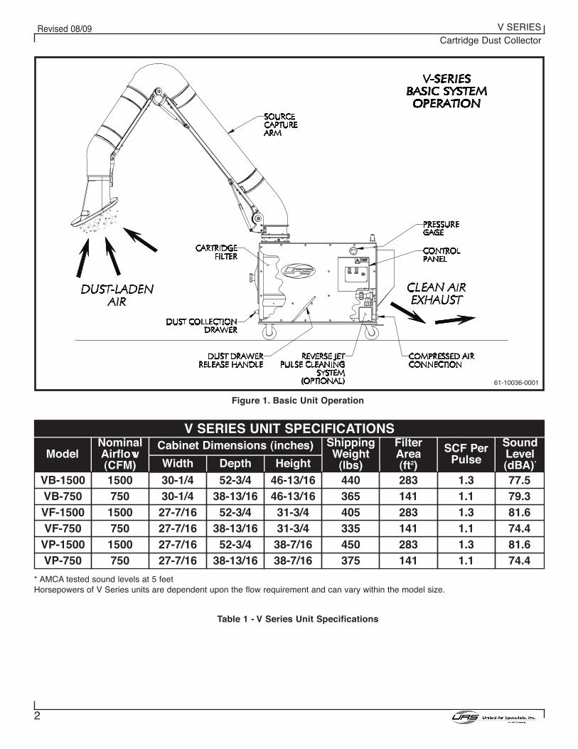
Figure 1 shows the basic system operation andequipment of a V Series dust collector.
2.3 AIR FILTERING OPERATION
The contaminated air stream is drawn into the collector.Once the dust-laden air enters the cabinet, it meets abaffle plate that disperses the air and significantlyreduces the air stream velocity. This provides evendistribution of the air stream across the entire surfacearea of the cartridge filters, allowing a uniform dustcake to form. The reduced air stream velocity causesthe heavier particles to fall out and collect in the dustdrawer.
The air stream then passes through the cartridge filterwhere it is stripped of the particles by the media.Cleaned air flows through the center of the filter,through the blower (and optional safety after filters andexits through the rear of the cabinet, back into theworkplace.
2.4 FILTER CLEANING CYCLE
As the cartridge filter becomes loaded withcontaminants, it becomes necessary to clean the filterto maintain adequate airflow.
The compressed air cleaning mechanism provides briefbursts of compressed air into the cylindrical cartridgefilter. When actuated, the cleaning system directs 90-100 PSI of customer supplied compressed air through apulse valve, into a blow pipe, creating a burst ofpressure through the inside of the cartridge filter. Thispressure dislodges the dust and reduces the pressuredrop across the filter so the system can maintainadequate airflow.
3. SPECIFICATIONS
Air Collection Method:
The V Series dust collector comes in three basic dustcollection configurations.
1. Downdraft Bench Unit (VB)
2. Fixed Ducted Unit (VF)
3. Portable Unit w/ Swing Arm (VP)
Within these variations, the units have two differentmodels, the 750 and the 1500.
Cleaning Options:
There are two basic filter-cleaning options with the V Series: a cleaning system utilizing compressed airand an option where the filters are cleaned manually,external to the dust collector cabinet by the customer.
Power Supply Options:
All 1-1/2 HP motors are available in 115-230/1/60 and200,230,460,575/3/60. All 3 HP Motors are available in200,230,460,575/3/60.
V X - X X X XCollection MethodNominal Flow Rate
2
Revised 08/09 V SERIESCartridge Dust Collector
61-10036-0001
Figure 1. Basic Unit Operation
Table 1 - V Series Unit Specifications
V SERIES UNIT SPECIFICATIONS
ModelNominalAirflow(CFM)
VB-1500VB-750VF-1500VF-750
VP-1500VP-750
1500750
1500750
1500750
Cabinet Dimensions (inches)
Width Depth Height
30-1/430-1/427-7/1627-7/1627-7/1627-7/16
52-3/438-13/1652-3/4
38-13/1652-3/4
38-13/16
46-13/1646-13/1631-3/431-3/438-7/1638-7/16
ShippingWeight
(lbs)440365405335450375
Filter Area(ft2)283141283141283141
SCF PerPulse
1.31.11.31.11.31.1
SoundLevel(dBA)*
77.579.381.674.481.674.4
* AMCA tested sound levels at 5 feetHorsepowers of V Series units are dependent upon the flow requirement and can vary within the model size.

3
Revised 08/09 V SERIESCartridge Dust Collector
See below for the amperage requirements of your unit,given the horsepower and power supply. The unitnameplate will provide the electrical specifications ofyour V Series system.
Motor HP1.51.51.51.51.51.53333
Power Supply115/1/60230/1/60200/3/60230/3/60460/3/60575/3/60200/3/60230/3/60460/3/60575/3/60
Amp Draw16.48.45.24.82.41.98.47.83.93.1
Standard Unit Options:
HEPA After Filter, Carbon Odor After Filter, Pre-WiredMotor Starter Panels
Filter Media Options:
Protura® Nanofiber, Protura® Nanofiber Fire Retardant,Poly-Fiberglass, Spun-Bond Polyester
See Table 1 on page 2 to see the operatingspecifications on your V Series system.
4. INSTALLATION
4.1 OFF LOADING AND INSPECTION
The V Series dust collector is shipped in two or threecontainers depending on the configuration and optionsselected. The first consists of the unit cabinet andfiltration components. Other container(s) may containthe extraction arm, downdraft bench, etc.
Upon receipt of your unit, check for any shippingdamage. A damaged carton indicates that theequipment may have received rough handling duringshipping that may have caused internal damage. Notifyyour delivery carrier and enter a claim if any damage isfound.
Remove the filter access cover (located on the front ofthe unit) by turning the black knob counterclockwise torelease the cover. Examine the seal between thetubesheet (the vertical panel between the blowersection and the filter section) and filter. Make sure filteror gasket has not become displaced during shipment(refer to Section 6.1, Cartridge Filter Removal andReplacement). Replace covers once inspection iscomplete.
4.2 INSTALLATION
Different models of the V Series collector requiredifferent assembly techniques. Please see thetechniques in the subsequent sections for your V Series dust collector.
All models of the V Series will require minimumclearances and access in order to perform routinemaintenance and service. Be sure to leave access forfilter removal, the dust drawer release lever and blower/pulse valve access through the discharge panel as shown in Figure 1.
4.2.1 PORTABLE INSTALLATION (VP MODEL)
The top of the V Series cabinet has either one set of six (VP-750) or eight (VP-1500) threaded studs tomount the swing arm. The necessary hardware is pre-assembled the studs. When mounting the arms on the unit, a ceiling height of about 10’ is required foradequate clearance. Two people are suggested forpositioning the swing arm and securing into place.
1. Remove the swing arm from its shippingcontainers and assemble per the swing armmanual provided.
2. Remove nuts, lock washer and flat washer fromthe studs on the cabinet (refer to Figure 2).
3. Position flange gasket(s) inside the protrudingstuds on top of the unit (refer to Figure 2).
4. Position the swing arm mounting base into placeover the mounting studs. Ensure gasket ispositioned properly between unit and baseflange. Secure swing arm to cabinet top with therecently removed hardware (refer to Figure 2).Avoid sharp pulls on the arm or hood as well asover-tightening the pivot section since damage tothe arm components could result.
Figure 2. Swing Arm Installation Detail
Table 2 - Unit Amperage Requirements
61-10036-0002

4
Revised 08/09 V SERIESCartridge Dust Collector
4.2.2 DOWNDRAFT TABLE ASSEMBLY (VB MODEL)
The V Series downdraft table (VB) comes packaged,requiring some assembly before using. Follow the steps below to complete the assembly.
1. Begin by securing the two side panels as shownin Figure 3. Thread all four fastening knobs intothe cabinet leaving enough space for the sidepanel to fit over top of threaded knob stud.
2. Lower each panel as shown onto the knob studsand then tighten knobs until panel is secure.
3. Lower the back panel into rear aligning tray andside panel guide slots.
4.2.3 FIXED UNIT ASSEMBLY (VF MODEL)
The fixed unit assembly typically requires some type ofcustomer-supplied ductwork to convey the dust from thesource to the collector. See Figure 4 for a typicalinstallation.
Care should be taken when sizing and laying out theductwork in order to minimize loses through the system.
Figure 3. Downdraft Table Installation Detail
61-10037-0001
4.3 PULSE CLEANING
If your V Series system came with a cleaning system,please review the following section for optimumperformance.
Provide a clean, dry, 90-110 PSIG compressed airsupply to the compressed air manifold. The supplycoupling (1" NPT) is located on the lower center of theunit’s rear panel as shown in Figure 7. A reducerbushing may be required for your supply line.
Compressed air supply to the unit can be a flexiblequick disconnect air line from a ceiling-mounted hosereel or similar supplied plant air. The hose size can bebetween 1/4” and 1” diameter.
The compressed air usage per cleaning cycle can befound in Table 1. Note that the cleaning system will onlyoperate when the motor/blower is off. See Section 4.4.1for adjustments available with the timer board.
4.4 ELECTRICAL INSTALLATION
The V Series unit has a wide variety of availableelectrical options to best meet your needs. Take careto ensure proper installation in whatever configurationyou have selected.
For units only requiring a 115-volt, single-phase powersupply, your unit will be supplied with a 15-foot powercord and plug and is electrically ready for operation. Ifthe unit has a 230-volt, single-phase power supply, theunit will be provided with a power cord but the customerwill be responsible for supplying and attaching theappropriate plug.
For units requiring three-phase power, there are twobasic options. If UAS is supplying the motor starter, theunit will be equipped with a 15-foot power cord withouta plug.
NOTE: All VP Series units come standard with a UASsupplied starter
If the customer is supplying the motor starter, no cord,motor overload protection or control transformer will beprovided.
Refer to Appendix A of this manual for therecommended wiring diagrams of your V Series unit.
4.4.1 PULSE CONTROL TIMER BOARD
Before making any changes to the Pulse Controlsettings, please read this section of the manual.
The Pulse Control timer board has been designed topulse a single solenoid valve that supplies a pulse ofcompressed air to a dust collector filter. Unlessotherwise specified, the timer board is factory set to a0.1 second pulse duration, 10 second pulse delay, and1 downtime cleaning cycle.Figure 4. Typical Fixed Unit Installation
61-10038-0001
5
Revised 08/09 V SERIESCartridge Dust Collector
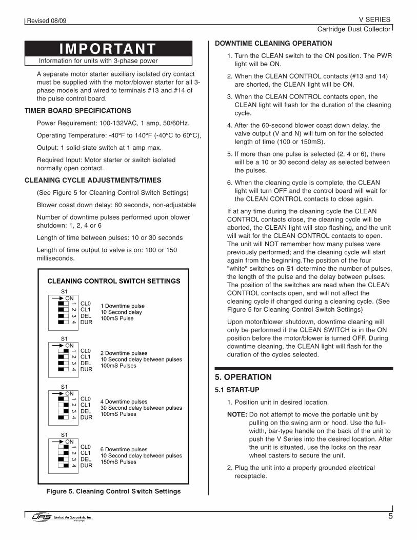
DOWNTIME CLEANING OPERATION
1. Turn the CLEAN switch to the ON position. The PWRlight will be ON.
2. When the CLEAN CONTROL contacts (#13 and 14)are shorted, the CLEAN light will be ON.
3. When the CLEAN CONTROL contacts open, theCLEAN light will flash for the duration of the cleaningcycle.
4. After the 60-second blower coast down delay, thevalve output (V and N) will turn on for the selectedlength of time (100 or 150mS).
5. If more than one pulse is selected (2, 4 or 6), therewill be a 10 or 30 second delay as selected betweenthe pulses.
6. When the cleaning cycle is complete, the CLEANlight will turn OFF and the control board will wait forthe CLEAN CONTROL contacts to close again.
If at any time during the cleaning cycle the CLEANCONTROL contacts close, the cleaning cycle will beaborted, the CLEAN light will stop flashing, and the unitwill wait for the CLEAN CONTROL contacts to open.The unit will NOT remember how many pulses werepreviously performed; and the cleaning cycle will startagain from the beginning.The position of the four"white" switches on S1 determine the number of pulses,the length of the pulse and the delay between pulses.The position of the switches are read when the CLEANCONTROL contacts open, and will not affect thecleaning cycle if changed during a cleaning cycle. (SeeFigure 5 for Cleaning Control Switch Settings)
Upon motor/blower shutdown, downtime cleaning willonly be performed if the CLEAN SWITCH is in the ONposition before the motor/blower is turned OFF. Duringdowntime cleaning, the CLEAN light will flash for theduration of the cycles selected.
5. OPERATION
5.1 START-UP
1. Position unit in desired location.
NOTE: Do not attempt to move the portable unit bypulling on the swing arm or hood. Use the full-width, bar-type handle on the back of the unit topush the V Series into the desired location. Afterthe unit is situated, use the locks on the rearwheel casters to secure the unit.
2. Plug the unit into a properly grounded electricalreceptacle.
A separate motor starter auxiliary isolated dry contactmust be supplied with the motor/blower starter for all 3-phase models and wired to terminals #13 and #14 ofthe pulse control board.
TIMER BOARD SPECIFICATIONS
Power Requirement: 100-132VAC, 1 amp, 50/60Hz.
Operating Temperature: -40ºF to 140ºF (-40ºC to 60ºC),
Output: 1 solid-state switch at 1 amp max.
Required Input: Motor starter or switch isolatednormally open contact.
CLEANING CYCLE ADJUSTMENTS/TIMES
(See Figure 5 for Cleaning Control Switch Settings)
Blower coast down delay: 60 seconds, non-adjustable
Number of downtime pulses performed upon blowershutdown: 1, 2, 4 or 6
Length of time between pulses: 10 or 30 seconds
Length of time output to valve is on: 100 or 150milliseconds.
Figure 5. Cleaning Control Switch Settings
IMPORTANTInformation for units with 3-phase power

6
Revised 08/09 V SERIESCartridge Dust Collector
6. SERVICE
Figure 7. Rear Access
61-10039-0001
Collected dust may be hazardous. Consult properauthorities for handling and disposal.
4. The filter monitor gauge should read between 0.1" and 0.5" w.g. while unit is operating with clean filters.
5. The discharge plenum on the V Series collectorcan be rotated in 90 increments to direct thedischarge air in multiple directions. The dischargehousing will be factory installed with the dischargepointing towards the floor as shown in Figure 7.
Collecting Particles
1. Locate the unit, arm and hood in the best positionto collect contaminants as generated by theprocess or operation, and where operatorinterference is minimal.
2. Position the hood to minimize the influence ofcross drafts from outside air sources or otheroperations.
3. Position the hood slightly higher than the source,with the face of the hood approximately 45° fromhorizontal. The hood shape is designed for high-velocity pick up. It should be located as close tothe source as practical and no further than 14-16"from the contaminant source.
3. Check diaphragm valves to ensure proper pulsecleaning. With the cleaning cycle activated, the valveshould pulse at approximately 10-second intervals.Remove lid of control panel enclosure to view thetimer.
4. Check the filter monitor gauge at start-up. Thecleaning system should be activated when the gaugehas increased 0.5" w.g. above the start-up pressuredrop. Allow unit to pulse clean until the originalreading is achieved or until the gauge reading willnot decrease after six consecutive pulses.
5.2 CHECKLIST
1. Check the clean air outlet. Discharge air shouldremain visibly clean. If a leak should develop, it willbe first noticed after a cleaning pulse as a puff ofdust.
2. Check pressure drop on the pressure gauge (see Figure 6). Pressure drop across elements isconsidered normal between 0.5-5.0" w.g. Pressuredrop will generally read between 1-2" for “seasoned”filters.
The following procedure requires access to an area ofthe unit where high voltage is present. Access shouldbe restricted to qualified personnel.
Figure 6. Control Panel Layout Detail
61-10039-0002
3. Turn the unit on by pushing the "Power" rockerswitch to the ON position (refer to Figure 6). On 3-phase units, fan rotation will need to be verified by matching fan rotation with the rotation decal onthe blower housing. Rotation should be clockwise as viewed from the motor or drive side. Any twomotor starter leads should be reversed if the rotation is not correct.

7
Revised 08/09 V SERIESCartridge Dust Collector
1. Collected dust may be a potential fire hazard. Referto Section 1 of this manual.
2. Wear appropriate protective clothing.
3. Be environmentally aware of collected dust and itsproper disposal.
4. Press unit function switch to OFF position. Unplugunit from electrical power source.
5. Disconnect compressed air supply to air manifoldinlet and bleed air supply from manifold.
6.1 FILTER REMOVAL AND REPLACEMENT
As the V Series unit operates and the filter accumulatesdust, the flow rate of the unit will deteriorate. When thepressure drop across the filter continuously readsbetween 2"-3" or flow drops off to the point where thedust generation process cannot adequately becontrolled, then it is time to change filters. To changefilters follow these steps:
1. Remove filter access cover by unscrewing theretaining knob (see Figure 8). Tilt cover back awayfrom unit when freed from the retaining nut to trapany fugitive dust on the inside of the access cover.Dump dust into suitable disposal container.
2. Move filter from side to side to break gasket sealbetween the filter and the tubesheet. Rotate the filter180° to allow dust on top of the cartridge to fall intothe dust drawer.
3. Slide filter out along support rods and transfer tosuitable disposal container. Empty dust drawer asdescribed in Section 6.2.
4. Inspect tubesheet and make sure the gasket sealingarea is free of dust to ensure a proper seal.
5. Install a new filter element. Clean access covergaskets and reinstall cover by tightening the knobsecurely to the retaining nut until the gasket isadequately compressed.
Figure 8. Cartridge Filter Removal
61-10039-0003
6.2 DUST DRAWER REMOVAL
1. To access and remove the dust drawer located at thebase of the V Series unit, you must first unseal thedrawer by pulling the drawer release handle (seeFigure 8) toward the filter access side of the cabinet.The drawer will move down and can be pulled out ofthe front of the cabinet.
2. Dispose of the collected dust into a suitablecontainer. Any dust in the cabinet that was notcontained in the dust drawer should be vacuumedout and disposed of.
3. Replace dust drawer by fully inserting into unit, andreseal the drawer by pushing the drawer releasehandle toward the control panel.
The collector should now be ready to operate. Reconnectelectrical power and air supply. Go through initial start-upchecklist to ensure proper unit performance.
6.3 AFTER-FILTER REMOVAL/INSTALLATION
If your unit was ordered with a HEPA or carbon after-filter,there will be an additional filter housing bolted to thedischarge side of the V Series unit. The following steps willallow you to remove and replace the after-filter as shown inFigure 9. NOTE: After-filter housings for portable units (VP)have a push handle located on the top of the housing.
1. Release the four draw latches located on the filterhousing to release the seal of the after-filter.
2. Remove the exhaust screen.
3. The after-filter will slide out of the housing as shownin Figure 9. Keep in mind that the filter weight maysignificantly increase from the collected material.Dispose of filter properly.
Figure 9. After-Filter Removal
61-10040-0001

8
Revised 08/09 V SERIESCartridge Dust Collector
4. Install a new filter element by sliding it into the filterhousing with the gasket of the after-filter leading.
5. Replace the exhaust screen and secure the fourdraw latches to seal the filter.
6.4 SERVICING DIRECT DRIVE BLOWER
To gain access to the direct drive motor/blower youmust first remove the discharge air plenum as shown inFigure 7.
NOTE: The blower rotation should be clockwise whenlooking at the motor from the discharge side ofthe cabinet.
See the troubleshooting guide in Section 8 of thismanual for clues on motor/blower problems.
7. ELECTRICAL
Tables 1 and 2 provide a listing of V Series modelnumbers and their corresponding voltage, motorhorsepower and full load amperage draw.
Please complete the provided blanks on the insidecover of this manual. This will help you to identify yourunit when dealing directly with United Air Specialists oryour local UAS representative.
7.1 UNIT CONTROL (ON/OFF)
All units will have the blower controlled from the unitcontrol panel (refer to Figure 6). A black ON/OFF rockerswitch is provided to start/stop the blower.
7.2 CLEANING CONTROLS (ON/OFF)
Section 4.4.1 of this manual clearly outlines theavailable settings and operation of the pulse cleaningsystem.
Control of the reverse pulse cleaning system is by arocker switch on the unit control panel (refer to Figure6). The pulse cleaning system operates independent ofthe blower. This provides for off-line cleaning.
NOTE: Compressed air must be connected prior toengaging cleaning system to prevent damage todiaphragm valves.
Electrical Schematics
An electrical schematic was included with your unit inthis packet. Please secure the drawing to this manualfor future reference. A copy of the appropriate wiringdiagram is also affixed on the inside of the controlpanel.

9
Revised 08/09 V SERIESCartridge Dust Collector
8. TROUBLESHOOTING
The Swing Arm slips fromset position.
The joints require adjustment. Adjust the joints (refer to Section 8.2 of theSwing Arm Manual)
Grease the rotation socket.
A) Clean out blockage.B) Reconnect hose.C) Replace damaged hose.D) Open arm damper.E) Check downstream filters, replace or clean
as needed.
Strong resistance duringrotation of the arm.
Decrease in air volume.
Motor/blower won’t startor won’t stay running.
Dust emissions from cleanair discharge
Insufficient airflow
Continual excessivepressure drop (over 5.0”)on filter monitor gauge.
Pulsing failure ofdiaphragm valve.
Filter element installed incorrectly; gasket notsealing.
Inspect and reinstall filter cartridge (refer toSection 6.1).
Replace damaged filter element.
Check fan rotation to ensure clockwiserotation (refer to Section 5).
Check for obstructions and clear.
Replace filters.
Cleaning system not being used at requiredfrequency. Increase frequency.
Check air supply pressure (should be 90-110PSIG).
Replace filters.
Check continuity of solenoid coil withohmmeter. Replace if necessary.
Filter element damaged.
Fan rotation backwards.
Air inlet restricted.
Filters at end of service life.
Plugged filter elements.
Inadequate compressed air supply forcleaning mechanism.
Filter elements at end of useful life.
Open solenoid valve.
Improper electrical supply. Refer to Section 7 for electrical specifications.
Starter overloadtripped. Reset overloads.
Lack of grease in the rotating socket.
A) The ventilation duct is plugged.B) Flexible hose not properly connected to
arm tubes.C) The flexible hose is damaged.D) The Swing Arm damper is closed.E) Packed filters or other
restriction in system.
PROBLEM POSSIBLE CAUSE RECOMMENDED SOLUTIONS
Timer does not operate. “PWR” light dose not illuminate.
Downtime cleaning does not function. PWR light not illuminated.
Downtime cleaning does not function. PWR light illuminated but CLEAN light notilluminated or flashing.
Downtime cleaning does not function. CLEAN light flashing but valve does notpulse.
1. Make certain 120VAC power is at terminals L and N. 2. Check fuses F1 and F2 for open circuit. If F1 is open, check wiring and
replace fuse. If F2 is open, replace board.
1. Make certain 120VAC power is at terminals L and N even after themotor/blower is turned off. The PWR light should be illuminated.
2. In units with motor starters: make certain an isolated normally openmotor starter auxiliary contact is wired to terminals 13 and 14 (downtimecleaning begins when the motor/blower starter is turned off.)
1. Check terminals V and N for 120VAC pulse. If no output when PULSElight flashes, replace board. If 120VAC pulse is detected, check wiring,valve coil and air supply.
PROBLEM RECOMMENDED SOLUTIONS

ELECTRICAL ENCLOSURE REPLACEMENT PARTS
10
Revised 08/09 V SERIESCartridge Dust Collector
ELECTRICAL ENCLOSURE REPLACEMENT PARTSItem No.
1
2
3
4
Not Shown
General Description
CONTACTOR, MOTOR
OVERLOAD RELAY (3-PHASE, 1-1/2 HP, 208,230 V)OVERLOAD RELAY (3-PHASE, 1-1/2 HP, 460 V)OVERLOAD RELAY (3-PHASE, 1-1/2 HP, 575 V)OVERLOAD RELAY (3-PHASE, 3 HP, 208,230 V)OVERLOAD RELAY (3-PHASE, 3 HP, 460,575 V)
CONTROL BOARD, CLEANING SYSTEM
TRANSFORMER, STEP-DOWN TO 120V (200-208V)TRANSFORMER, STEP-DOWN TO 120V (230-460V)TRANSFORMER, STEP-DOWN TO 120V (575V)
SWITCH, ROCKER, DPST
UAS Part No.
23-3124-9
23-3124-5.023-3124-3.123-3124-2.423-3124-8.523-3124-4.0
20-3232
21-1275-05021-1274-05021-1276-050
20-2920
61-10041-0002Panel shown is with UAS supplied starter

11
Revised 08/09 V SERIESCartridge Dust Collector
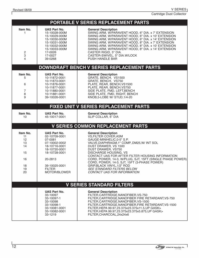
PORTABLE V SERIES REPLACEMENT PARTS
12
Revised 08/09 V SERIESCartridge Dust Collector
Item No.1
234
General DescriptionSWING ARM, W/PARAVENT HOOD, 6" DIA. x 7' EXTENSIONSWING ARM, W/PARAVENT HOOD, 6" DIA. x 10' EXTENSIONSWING ARM, W/PARAVENT HOOD, 6" DIA. x 14' EXTENSIONSWING ARM, W/PARAVENT HOOD, 8" DIA. x 7' EXTENSIONSWING ARM, W/PARAVENT HOOD, 8" DIA. x 10' EXTENSIONSWING ARM, W/PARAVENT HOOD, 8" DIA. x 14' EXTENSIONCASTER RIGID, 5" DIA.CASTER-SWIVEL, 5" DIA.W/LOCKPUSH HANDLE BAR
UAS Part No.15-10028-000M15-10029-000M15-10030-000M15-10031-000M15-10032-000M15-10033-000M17-002617-002739-0268
Item No.5
6
789
General DescriptionGRATE, BENCH, VS1500GRATE, BENCH, VS750PLATE, REAR, BENCH,VS1500PLATE, REAR, BENCH,VS750SIDE PLATE, FMD, LEFT,BENCHSIDE PLATE, FMD, RIGHT, BENCHKNOB,5-LOBE W/ STUD,1/4-20
UAS Part No.10-11872-000110-11873-000110-11876-000110-11877-000110-11880-000110-11881-000139-10026-0001
Item No.10
General DescriptionSLIP COLLAR, 6” DIA
UAS Part No.45-10017-0001
Item No.11121314
15
16
181920
General DescriptionVS,FILTER COVER,ASMGAUGE-MINIHELIC,0-5" S.P.VALVE,DIAPHRAGM,1" COMP.,DM25,W/ INT SOLDUST DRAWER, VS 1500DUST DRAWER, VS750DISCHARGE HOUSING, VSCONTACT UAS FOR AFTER FILTER HOUSING INFORMATIONCORD, POWER, 14-3, W/PLUG, SJT, 15FT (SINGLE PHASE POWER)CORD, POWER, 14-3, SJT, 15FT (3-PHASE POWER)GRIP,BLACK VINYL,1/2" RODSEE STANDARD FILTERS BELOWCONTACT UAS FOR INFORMATION
UAS Part No.02-10709-000107-008107-10002-000218-10716-000118-10720-000118-10728-0001
20-2813
39-10025-0001FILTERMOTOR/BLOWER
General DescriptionFILTER,CARTRIDGE,NANOFIBER,VS-750FILTER,CARTRIDGE,NANOFIBER FIRE RETARDANT,VS-750FILTER,CARTRIDGE,NANOFIBER,VS-1500FILTER,CARTRIDGE,NANOFIBER,FIRE RETARDANT,VS-1500FILTER,HEPA 99.97,23.375x23.375x11.5,UP GASK>FILTER,HEPA 99.97,23.375x23.375x5.875,UP GASK>FILTER,CHARCOAL,24x24x6
UAS Part No.33-1009733-10097-133-1009833-10098-133-10081-000133-10082-000133-1219
PORTABLE V SERIES REPLACEMENT PARTS
DOWNDRAFT BENCH V SERIES REPLACEMENT PARTS
FIXED UNIT V SERIES REPLACEMENT PARTS
V SERIES COMMON REPLACEMENT PARTS
V SERIES STANDARD FILTERS

13
Revised 08/09 V SERIESCartridge Dust Collector
APPENDIX A. V SERIES WRING DIAGRAM
Figure 10. Wiring Diagram 120 Volt, Single Phase, Manual Clean
Figure 11. Wiring Diagram 120 Volt, Single Phase, Pulse Cleaning
Figure 12. Wiring Diagram 230 Volt, Single Phase, Manual Clean
41-2537
41-2538
41-2541

14
Revised 08/09 V SERIESCartridge Dust Collector
Figure 14. Wiring Diagram, Three Phase, Manual Clean w/ UAS Supplied Starter
Figure 13. Wiring Diagram 230 Volt, Single Phase, Pulse Cleaning41-2542
41-2543

15
Revised 08/09 V SERIESCartridge Dust Collector
Figure 15. Wiring Diagram, Three Phase, Pulse Cleaning w/ UAS Supplied Starter
Figure 16. Wiring Diagram, Three Phase, Manual Clean w/ Customer Supplied Starter
41-2544
Figure 17. Wiring Diagram, Three Phase, Pulse Cleaning w/ Customer Supplied Starter41-2546
41-2545

©2004 United Air SpecialistsPart No. 44-10448-000108/09
United Air Specialists, Inc. reserves the right to change
design or specifications without notice.
4440 Creek Road • Cincinnati, Ohio 45242 USANational Phone: 1-800-252-4647
Telephone: (513) 891-0400 • Fax: (513) 891-4882www.uasinc.com
UNITED AIR SPECIALISTS, INC.LIMITED WARRANTY
UAS warrants to the original purchaser that all equipment will be free from defects in materials andworkmanship for one year from the date of shipment from UAS (three years for Smokeeter® andVisionAir™ models other than CC and DC series) and that major structural components on SFC and MCBseries will be free from defects in materials and workmanship for ten years from the date of shipment fromUAS. This warranty applies only if equipment is properly installed, maintained, and operated under normalconditions and does not apply to damage caused by corrosion, abrasion, abnormal use or misuse,misapplication, or normal wear and tear. This warranty will be void with respect to equipment that is subjectto unauthorized repairs or modifications. UAS makes no warranty as to goods manufactured or supplied byothers. This warranty is subject to any limitations in UAS’ quotation and may not be modified except by awritten instrument signed by the President or Vice President of Sales of UAS.
THIS WARRANTY IS EXCLUSIVE AND IN LIEU OF ALL OTHER WARRANTIES, WHETHERWRITTEN, ORAL OR IMPLIED, INCLUDING ANY IMPLIED WARRANTY OFMERCHANTABILITY, FITNESS FOR A PARTICULAR PURPOSE OR NONINFRINGEMENT.
As Purchaser's exclusive remedy for any defects in the equipment, UAS will exchange or repair anydefective parts during the warranty period, provided such parts are returned, prepaid, to UAS' factory. Theobligation of UAS is limited to furnishing replacement parts F.O.B. UAS' factory or making repairs at UAS'factory of any parts that are determined, upon inspection by UAS, to be defective. In no event will UAS beresponsible for labor or transportation charges for the removal, reshipment or reinstallation of the parts.
IN NO EVENT WILL UAS BE RESPONSIBLE FOR ANY SPECIAL OR CONSEQUENTIALDAMAGES.