4401 oxy-trace v4 - sensors manual 4401 v8.pdf · the 4401 oxy-trace v4 is the precision oxygen...
TRANSCRIPT

Instruction Manual
4401 Oxy-Trace v4 Fiber-optic trace oxygen meter
Manual Version 8
Instruction Manual 4401 Oxy-trace v4
PC Software Version 4401TRACEv1.14
October 2006
Specification:
Stand-alone one-channel fiber-optic oxygen meter with graphical LCD and Data-logger for oxygen mini-sensors. PC control of the oxygen meter is available. Excitation wavelength of 505 nm. Polymer optical fibers (POF) of 2 mm diameter connected by SMA fiber connectors. Manufacturer: Barben Analyzers Technology L.L.C. 5200 Convair Drive Carson City, Nevada 89706 USA Phone (800) 993-9309 Fax (775) 297-4740 Email [email protected] Internet www.BAT4pH.com

Table of Contents 2
Table of Contents 1 Preface ............................................................................................................................ 5 2 Safety Guidelines ........................................................................................................... 6 3 Description of the 4401 Oxy-trace v4 Device .............................................................. 8 4 Required Basic Equipment ......................................................................................... 10 5 Planar Oxygen Minisensors ........................................................................................ 11
5.1 Sensor Characteristic of Oxygen-Sensitive Minisensors ................................. 11 5.2 Housings of Oxygen-Sensitive Minisensors ..................................................... 14
5.2.1 Planar Trace Oxygen-Sensitive Spots ....................................................................................... 15 5.2.2 Flow-Through Cell with Integrated Planar Trace Oxygen Sensor .............................................. 18 5.2.3 Trace Oxygen Dipping Probe .................................................................................................... 20 5.2.4 Oxygen Probe for Inline Measurements (OIM) .......................................................................... 22 5.2.5 OIM Exchange Cap (OEC) ........................................................................................................ 23 5.2.6 Oxygen Exchange Window (OEW-xx) ....................................................................................... 24
6 Working with the 4401 Oxy-trace v4 ........................................................................... 26 6.1 Starting the Instrument ........................................................................................ 26 6.2 Setting the sensor type ........................................................................................ 27 6.3 Setting Measurement Parameters ...................................................................... 28 6.4 Calibration ............................................................................................................ 29 Before starting the measurement you have to choose the correct sensor type (BOS1, BOS2,
BOS3). To change the sensor type you have to press the ‘Menu’ button and afterwards the ‘Calibration’ button. In the Calibration Menu you find the button ‘Sensor type’ which you have to press to change the sensor. .......................................................... 29
6.4.1 Calibration Standards for the respective oxygen sensors .......................................................... 29 6.4.2 Calibration of the BOS2 oxygen sensor ..................................................................................... 30 6.4.3 Calibration of the BOS1 oxygen sensor ..................................................................................... 34 6.4.4 Calibration of the BOS3 oxygen sensor ..................................................................................... 36
6.5 Data Logging ........................................................................................................ 37 6.6 Configuration ........................................................................................................ 38 6.7 Diagnostics and Test ........................................................................................... 41 6.8 Menu Structure ..................................................................................................... 42
7 Description of 4401 Oxy-trace v4 PC Software ......................................................... 43 7.1 Software Installation and Starting the Instrument ............................................ 43 7.2 Function and Description of the 4401 Oxy-trace v4 Program .......................... 43 4. Control bar, divided into numerical display, control buttons and warning lights 44
7.2.1 Menu Bar ................................................................................................................................... 45 7.2.2 Control Bar ................................................................................................................................ 51 7.2.3 Graphical Window ...................................................................................................................... 57 7.2.4 Status Bar .................................................................................................................................. 57
7.3 Error Codes .......................................................................................................... 58 7.4 Subsequent Data Handling.................................................................................. 58

Table of Contents 3
8 Calibration of BOS2 Oxygen-Sensitive Fiber-Optic Minisensors ............................ 60 8.1 Preparation of the Calibration Standards .......................................................... 60 8.2 Mounting the Oxygen-Sensitive Minisensor and Sensor Spots ...................... 61
8.2.1 Oxygen Dipping Probe ............................................................................................................... 61 8.2.2 Oxygen flow through cell (FTC-BOS2-xx) .................................................................................. 61 8.2.3 Oxygen-Sensitive Spot (SP-BOS2-xx) ....................................................................................... 62
8.3 Calibration without Automatic Temperature Compensation ........................... 63 8.4 Calibration with Automatic Temperature Compensation ................................. 67 8.5 User defined Calibration ...................................................................................... 68
9 Calibration of Trace Oxygen Sensor BOS1 ............................................................... 70 9.1 Preparation of the Calibration Standards .......................................................... 70 9.2 Mounting the Trace Oxygen-Sensitive Minisensor and Sensor Spots ........... 70
9.2.1 Trace Oxygen Dipping Probe (DP-BOS1-xx) ............................................................................. 70 9.2.2 Trace Oxygen Flow Through Cell (FTC-BOS1-xx) .................................................................... 70 9.2.3 Trace Oxygen-Sensitive Spot (SP-BOS1-xx) ............................................................................ 72
9.3 Calibration without Automatic Temperature Compensation ........................... 73 9.4 Calibration with Automatic Temperature Compensation ................................. 75 9.5 User defined Calibration ...................................................................................... 76
10 Calibration of Trace Oxygen Sensor BOS3 ............................................................... 77 10.1 Mounting the Trace Oxygen-Sensitive Minisensors ......................................... 77
10.1.1 Trace Oxygen Dipping probe (DP-BOS3-xx) ............................................................................. 77 10.1.2 Trace Oxygen Flow-Through Cell (FTC-BOS3-xx) .................................................................... 77 10.1.3 Trace Oxygen-sensitive spots (SP-BOS3-xx) ............................................................................ 79
10.2 Calibration without Automatic Temperature Compensation ........................... 80 10.3 Calibration with Automatic Temperature Compensation ................................. 82 10.4 User-Defined Calibration ..................................................................................... 82
11 Some Advice for Correct Measurement ..................................................................... 84 11.1 Signal drifts due to oxygen gradients ................................................................ 84 11.2 Signal drifts due to temperature gradients ........................................................ 84 11.3 Signal drift due to photo-decomposition ........................................................... 84 11.4 Signal drift due to too much ambient light ........................................................ 85 11.5 Performance proof ............................................................................................... 85 11.6 Correction for air-pressure variations ................................................................ 85
12 General Instructions: ................................................................................................... 87 12.1 Warm-Up Time ...................................................................................................... 87 12.2 Maintenance ......................................................................................................... 87 12.3 Error codes ........................................................................................................... 87 12.4 Service .................................................................................................................. 87

Table of Contents 4
13 Technical Data .............................................................................................................. 89 13.1 General Data ......................................................................................................... 89 13.2 Analog Output and Input channels ..................................................................... 90 13.3 Technical Notes .................................................................................................... 91 13.4 Operation Notes ................................................................................................... 91
14 Concluding Remarks ................................................................................................... 92 15 Appendix ....................................................................................................................... 93
15.1 Basics in Optical Sensing of Oxygen ................................................................. 93 15.1.1 Dynamic Quenching of Luminescence ...................................................................................... 93 15.1.2 Major Components of Fiber-Optic Minisensors .......................................................................... 94 15.1.3 Advantages of Optical Oxygen-Sensitive Minisensors ............................................................... 95 15.1.4 Luminescence Decay Time ....................................................................................................... 95 15.1.5 Literature ................................................................................................................................... 96
15.2 Oxygen Conversion Formulas ............................................................................ 97 15.3 Temperature Dependent Constants Affecting the Oxygen Content ................ 98
15.3.1 Water Vapor Pressure ............................................................................................................... 98 15.3.2 Bunsen Absorption Coefficient .................................................................................................. 99 15.3.3 Dependence on the Salt Concentration ................................................................................... 104

Preface
5
Preface
Congratulations! You have chosen the new innovative technology for measuring oxygen from Barben Analyzer Technology! The 4401 Oxy-trace v4 is a compact, easy to transport, stand-alone fiber optic oxygen meter. The data evaluation is PC supported. The 4401 Oxy-trace v4 was specially developed for small fiber optic oxygen sensors, flow trough cells and integrated sensor systems. It is based on a novel technology, which creates very stable, internal referenced measured values. This enables a more flexible use of oxygen sensors in many different fields of interest.
Optical oxygen sensors (also called optodes) have the following outstanding properties:
• They are small • They do not consume oxygen • Limit of detection up to 1 ppm oxygen in the gas phase (BOS3), or 1 ppb dissolved oxygen (BOS1) • On-line non-invasive and non-destructive oxygen measurements • They can measure in both liquids (BOS2, BOS1) as well as gas phase (headspace) (BOS2, BOS3) • Their signal does not depend on the flow rate of the sample • They have excellent long term stability • They can be physically divided from the measuring system which means a contact less
measurement. • They can be autoclaved and γ-sterilized as well (BOS2, BOS1)
Therefore, they are ideally suited for the examination of small sample volumes, long term measurements in difficult samples, and for biotechnological applications. A set of different oxygen mini-sensors, flow through cells and integrated sensor systems is available to make sure you have the sensor which is ideally suited to your application. Please feel free to contact our service team to find the best solution for your application. Thank you. Barben Analyzer Technology

Safety Guidelines
6
Safety Guidelines
PLEASE READ THESE INSTRUCTIONS CAREFULLY BEFORE WORKING WITH THIS INSTRUMENT! This device has left our works after careful testing of all functions and safety requirements.
The perfect functioning and operational safety of the instrument can only be ensured if the user observes the usual safety precautions as well as the specific safety guidelines stated in these operating guidelines.
- Before connecting the device to the electrical supply network, please ensure that the operating voltage stated on the power supply corresponds to the mains voltage
- The perfect functioning and operational safety of the instrument can only be maintained under the climatic conditions specified in Chapter 10 "Technical Data" in this operating manual.
- If the instrument is moved from cold to warm surroundings, condensate may form and interfere with the functioning of the instrument. In this event, wait until the temperature of the instrument reaches room temperature before putting the instrument back into operation.
- Balancing, maintenance and repair work must only be carried out by a suitable qualified technician, trained by us.
- Especially in the case of any damage to current-carrying parts, such as the power supply cable or the power supply itself, the device must be taken out of operation and protected against being put back into operation.
- If there is any reason to assume that the instrument can no longer be employed without a risk, it must be set aside and appropriately marked to prevent further use.
- The safety of the user may be endangered, e. g., if the instrument
• is visibly damaged; • no longer operates as specified; • has been stored under adverse conditions for a lengthy period of time; • has been damaged in transport
- If you are in doubt, the instrument should be sent back to the manufacturer Barben Analyzer Technology for repair and maintenance.
- The operator of this measuring instrument must ensure that the following laws and guidelines are observed when using dangerous substances:
• National protective labor legislation; • Safety regulations for accident prevention; • Safety data-sheets of the chemical manufacturer
The 4401 Oxy-trace v4 is enclosed in a NEMA 4 Stainless Steel enclosure; The 4401 Oxy-trace v4 can be used in either industrial or laboratory environment; The 4401 Oxy-trace v4 is rated NEMA 4, The 4401 Oxy-trace v4 is approved for Class I, Division II, Groups. A, B, C, and D (FM/CSA); We explicitly draw your attention to the fact that any damage of the manufacturers seal will render of all guarantee warranties invalid.
Any internal operations on the unit must be carried out by personal explicitly authorized by Barben Analyzer Technology and under antistatic conditions.

Safety Guidelines
7
The 4401 Oxy-trace v4 may only be operated by qualified personal. This measuring instrument was developed for use in the laboratory. Thus, we must assume that, as a result of their professional training and experienc e, the operators will know the necessary safety precautions to take when handling chemicals. Keep the 4401 Oxy-trace v4 and the equipment such as PT 100 temperature sensor, power supply and optical sensors out of the reach of children! As the manufacturer of the 4401 Oxy-trace v4, we only consider ourselves responsible for safety and performance of the device if
• The device is strictly used according to the instruction manual and the safety guidelines
• The electrical installation of the respective room corresponds to the DIN IEC/VDE standards and pending hazardous rating (FM 3611) Class 1, Division II, Groups A, B, C, and D.
The 4401 Oxy-trace v4 and the sensors must not be used in vivo examinations on humans! The 4401 Oxy-trace v4 and the sensors must not be used for human-diagnostic or therapeutic purposes!
“Warning”
The 4401OXY Transmitter assembly is not for use in atmospheres containing an oxygen concentration greater than 21% by volume.

Required Basic Equipment
8
Description of the 4401 Oxy-trace v4 Device
The 4401 Oxy-trace v4 is a precision, temperature compensated, stand-alone oxygen meter enclosed in a NEMA 4 stainless steel case, designed for fiber-optic oxygen mini-sensors.
Their rugged design and low power consumption makes it ready for indoor and outdoor application.
4401 Oxy-trace v4 instrument features:
• Fiber-optic oxygen meter with temperature & pressure* compensation • Programmable sampling rate • 128x64 pixel graphical LCD • 2 x 12bit, programmable voltage outputs with galvanic isolation • 2 x 12bit, programmable current outputs with galvanic isolation • 2 x 12bit, programmable analog voltage inputs with galvanic isolation • measuring range 0 – 250 % air saturation • 110 Vac Power (Optional 12 – 30 Vdc) • RS 232 interface • IP64 guard box * Option for external pressure sensor
The 4401 Oxy-trace v4 is the precision oxygen meter, designed for fiber-optic oxygen sensors. It is equipped with four independent Analog Outputs and two Analog Inputs. It is a stand-alone instrument with LCD and integrated data-logger. The analog outputs are programmable to oxygen, temperature, phase shift or signal amplitude. To allow external data collection, two input ports are available (i.e., external pressure sensor). The digital interface (RS232) and PC software (included) is used for data storage and visualisation. The built-in data-logger can store up to 26000 data samples.

Required Basic Equipment
9
Front Panel
ELEMENT DESCRIPTION FUNCTION
SMA SMA fiber connector
Connect the fiber optic oxygen mini-sensor here.
Power Line adapter for power supply
110 Vac power supply.
PT1000 Connector for PT 1000 temperature sensor
Connect the PT 1000 temperature sensor for temperature compensated measurements here.
RS232 RS232 interface Connect the device with a RS232 data cable to your PC/Notebook here (optional).
U1/U2 Analog out/input (channel 1/2)
Connectors analog input and output (Voltage 0-10 V). Connect external instruments e.g. temperature input, pressure input
I1/I2 Analog out (channel 1/2)
Connectors analog output (Current 4-20 mA).

Required Basic Equipment
10
Required Basic Equipment
• Oxygen meter 4401 Oxy-trace v4 *
• Line adapter (110 V AC, Optional 18 V DC) *
• Temperature sensor Pt 1000*
• Oxygen-sensitive mini-sensor The mini-sensors are mounted into different types of housings
• PC / Notebook (optional) (System requirements: Windows 98/2000/XP//Millenium/NT 4.0; Pentium processor, at least 133 MHz, 16 MB RAM)
• RS 232 Cable *
*: scope of supply

Planar Oxygen Mini-sensors
11
Planar Oxygen Mini-sensors
Sensor Characteristic of Oxygen-Sensitive Mini-sensors The principle of the sensor operation is based on the quenching of luminescence caused by collision between molecular oxygen and luminescent dye molecules in the excited state. Figure 5.1 shows a typical response curve of an oxygen-sensitive sensor. In the presence of oxygen the signal - in our case the phase angle Φ - decreases. The phase angle Φ can be related to the oxygen content as shown in Figure 5.2. The theoretical aspects are explained more detailed in the appendix.
Figure 5.1 Response of mini-sensor SP-BOS1 toward changes in the oxygen concentration.
Figure 5.2 Effect of the phase angle of mini-sensor SP-BOS1 on different oxygen contents
Specifications
INSTRUMENT 4401 Oxy-trace v4 (BOS1, BOS2, and BOS3 Oxygen Sensors) Channels 1 x optical channel (SMA connector) , designed for mini-sensors
1 x PT1000 connector
Temperature (PT1000) Range Resolution Accuracy 0-50°C ±0.2°C ±1°C
Digital interface RS 232 interface with galvanic isolation (19200 Baud, Data-bits 8), RJ connector (RJ 6/4 - SUB-D 9 cable for RS232 PC port included)
Analog outputs four independent, programmable 12bit analog I/O channels with galvanic isolation 2 x voltage output 0-10 V; 2 x current output 4-20 mA
Analog inputs four independent, programmable 12bit analog I/O channels with galvanic isolation 2 x voltage input 0-10 V; 2 x current input 4-20 mA
Specification Range Resolution Accuracy Analog output (Oxygen) 0-20% air-sat. ±0.2% air-sat. ±0.5% air-sat. Analog output (Temperature, PT1000) 0-50°C ±0.5°C ±1.5°C
Acquisition time Programmable (default 1 second) Power supply 18 VDC/max.830 mA (110-240 VAC, 50/60 Hz adapter)
SOFTWARE OxyView
Oxygen units User selectable from: air-saturation, oxygen-saturation, hPa, Torr, mg/L (=ppm), µmol
Compatibility Windows 95/98/2000/Millenium/NT4.0/2000/XP
Calibration Conventional two-point calibration in oxygen-free environment (nitrogen) and a second calibration value optimally between 1 and 2 % oxygen
ENVIRONMENTAL CONDITIONS Operating Temperature (°C) 0 to +50 Storage Temperature (°C) -10 to +65 Relative humidity (%) up to 95 (IP 64)
10
20
30
40
50
60
70
0 5 10 15 20
air-saturation [%]
phas
e an
gle
[°]
SP-BOS1-YOPpatm 995 mbarT = 20 °C
0
10
20
30
40
50
60
70
0 4 8 12 16 20 24
time [min]
phas
e an
gle
[°]
0 % a.s.0.5 % a.s.
1 % a.s.
3 % a.s.
6 % a.s.
10 % a.s.
0 % a.s.
SP-BOS1-YOPpatm 995 mbarT = 20 °C
20 % a.s.

Planar Oxygen Mini-sensors
12
Dimensions, DxWxH (mm) 8” x 10” x 8” Weight (kg) 2.2
Trace Oxygen Sensor Type BOS1 (Maximum Temperature 130º C with Limitation) Dissolved Oxygen Gaseous & Dissolved OxygenMeasurement range
0 - 1.8 mg/L (ppm) 0 – 56.9 µmol
0 - 20 % air-sat. 0 - 4.2 % oxygen-sat. 0 - 31.1 Torr 0 - 41.4 hPa
Limit of Detection (LOD) 0.01 % air-saturation, 1 ppb dissolved oxygen
0.02 hPa, 0.016 Torr
Resolution at 20 °C and 1013 hPa
1 ± 0.30 µg(L (ppb) 10 ± 0.40 µg(L (ppb) 100 ± 0.50 µg(L (ppb)
0.011 ± 0.003 %air-sat. 0.11 ± 0.004 %air-sat. 1 ± 0.005 %air-sat. 0.002 ± 0.0007 % O2 0.02 ± 0.0009 % O2 0.2 ± 0.0015 % O2
0.03 ± 0.010 µmol 0.31 ± 0.012 µmol 2.8 ± 0.020 µmol
0.017 ± 0.005 Torr 0.17 ± 0.007 Torr 1.5 ± 0.011 Torr 0.023 ± 0.007 hPa 0.23 ± 0.009 hPa 2.0 ± 0.015 hPa
Accuracy (20 °C) 3% of the respective concentration
Oxygen Sensor Type BOS2 (Maximum Temperature 130º C with Limitation) Dissolved Oxygen Gaseous & Dissolved OxygenMeasurement range
0 - 22 mg/L (ppm) 0 - 700 µmol
0 - 250 % air-sat. 0 - 50 % oxygen-sat. 0 - 380 Torr 0 - 500 hPa
Limit of Detection (LOD) 0.15 % air-saturation, 15 ppb dissolved oxygen
0.31 hPa, 0.23 Torr
Resolution at 20 °C and 1013 hPa
0.09 ± 0.005 mg/L (ppm) 2.72 ± 0.01 mg/L (ppm) 9.06 ± 0.05 mg/L (ppm) 22.65 ± 0.15 mg/L (ppm)
1 ± 0.05 % air-sat. 30 ± 0.1 % air-sat. 100 ± 0.5 % air-sat. 250 ± 1.7 % air-sat. 0.21 ± 0.01 % oxygen 6.3 ± 0.02 % oxygen 20.9 ± 0.1 % oxygen 52.4 ± 0.35 % oxygen
2.83 ± 0.14 µmol 85.0 ± 0.28 µmol 283.1 ± 1.4 µmol 798.0 ± 4.7 µmol
1.55 ± 0.08 Torr 46.7 ± 0.2 Torr 155.5 ± 0.75 Torr 388.8 ± 2.6 Torr 2 ± 0.1 hPa 60 ± 0.3 hPa 200 ± 1 hPa 500 ± 0.3 hPa
Accuracy (20 °C) ± 1% at 100 % air-saturation; ± 0.15% at 1 % air-saturation
Trace Oxygen Sensor Type BOS3 Gaseous Oxygen
Measurement range 0 – 200 ppm (Maximum Range 1000 ppm) Limit of Detection (LOD) 0.5 ppm Resolution at 20 °C and 1013 hPa 1 ± 0.15 ppm; 10 ± 0.15 ppm; 30 ± 0.15 ppm
Accuracy (20 °C) 5% of the respective concentration

Planar Oxygen Mini-sensors
13
Temperature Barben Analyzer Technology oxygen sensors can be used in the temperature range of -10 to 130 °C in certain applications. Barben Analyzer offers a Pt1000 temperature sensor in combination with the 4401 Oxy-trace to record temperature variations which are compensated using the 4401 Oxy-trace software.
Cross sensitivity:
There exists no cross sensitiv ity for carbon dioxide (CO2), hydrogen sulfide (H2S), sulfur dioxide (SO2), pH, any ionic species like sulfide (S2
- ), sulfate (SO42-), chloride (Cl-) or salinity. Turbidity and
changes in the stirring rate have no influence on the measurement.
The sensors can also be used in methanol- and ethanol-water mixtures as well as in pure methanol and ethanol. We recommend avoiding other organic solvents, such as acetone, chloroform or methylene chloride, which may swell the sensor matrix.
Response time The response time (t90, 90 % of the signal change has occurred) of the BOS1 oxygen sensor is less than 30 s in solution (non-stirred) and even less than 8 s in the gas phase.
The response time (t 90) of the oxygen sensor is dependent from the diffusion rate of oxygen through the sensor layer hence, the response time is dependent from the thickness of the sensor layer and the stirring rate. The response times (t90) of sensor foil BOS1 is listed in Table below. Unlike electrodes, optical sensors do not consume oxygen and the signal is independent of changes in flow velocity which means that stirring decreases the response time, but has no effect on the measured value.
Optical isolation of the oxygen-sensitive layer wh ich is applied to exclude ambient light and improve chemical resistance will slow down the sensor response.
Response time (t95) of the different oxygen sensors. dissolved oxygen gaseous oxygen stirred non-stirred
Trace oxygen sensor BOS1
t95 without optical isolation t95 with optical isolation
< 20 s < 30 s
< 40 s < 60 s
< 6 s < 10 s
oxygen sensor BOS2
t95 without optical isolation t95 with optical isolation
< 20 s < 30 s
< 40 s < 60 s
< 6 s < 10 s

Planar Oxygen Mini-sensors
14
Optical isolation
Optical isolated sensor tips are required, if your sample shows intrinsic fluorescence between 540 - 700 nm. Consequently, an optical isolation is recommended measuring in whole blood, urine or chlorophyll containing samples. Using optical isolated sensors exclude the impact of colored samples and ambient light on measurements. Furthermore, the optical isolation layer is applied to exclude strong ambient light, to improve chemical resistance especially against oily samples as well as to reduce bio-fouling on the sensor membrane.
Optical isolated sensor tips of oxygen sensors enable measurement in photo-synthetically active samples, since stimulation of photosynthesis, due to emission of blue-green light from the fiber tip, is avoided.
Barben Analyzer offers additional optical isolation for all types of oxygen sensors. Sensor Stability
The oxygen-sensitive membrane stands gamma-sterilization, sterilization by ethylene oxide, steam autoclaving (140 °C, 1.5 atm), CIP conditions (cleaning-in-place, 5% NaOH, 90°C), as well as a 3% H2O2 solution. The oxygen-sensitive material may be subject to photo-decomposition resulting in a signal drift. Photo-decomposition takes place only during illumination of the sensor tip and depends on the intensity of the excitation light. Sensor Drift at 0 % air-saturation (0 ppb) recording 3600, 50000 and 100000 data points. Drift per 3600 points Drift per 50000 points Drift per 100000 points BOS2 < 0.15 % air-sat. < 0.15 % air-sat. < 0.25 % air-sat. BOS1 < 1 ppb < 2 ppb < 3 ppb The sensor should be shielded from ambient light to obtain reliable data. A black overcoat, called optical isolation is strongly recommended to reduce ambient light. Housings of Oxygen-Sensitive Mini-sensors
Barben Analyzer fiber-optic oxygen sensors are based on 2 mm polymer optical fibers (POF). Depending on the respective application, Barben Analyzer offers a set of different standard designs.
12 mm Probe (13.5 pg) in 120 mm and 220 mm length
Flow through fitting with internal dipping probe
2 mm oxygen dipping probe
Of course, it is possible to build customer-specific designs. Please feel free to contact our service team to find the best solution for your application.

Planar Oxygen Mini-sensors
15
Planar Trace Oxygen-Sensitive Spots
Planar oxygen sensor spots immobilized onto different supports (polyester, glass) are available in a number of diameters for customer specific applications.
The sensor spots can be glued inside glass vials such as cell culture flasks, bags, disposables or side glasses. The oxygen concentration can be measured non-invasive and non-destructive by projecting the tip of polymer optical fiber (POF ) to the sensor spot from outside through the wall.
The optical w indow should not be thicker than 12 mm and has to be transparent and non fluorescent.
Features • non-invasive and non-destructive measurement
from outside through the wall of the flask • excellent mechanical stability and long-term stability
(more than 100000 data points without drift) • online monitoring • response time (t90) in the order of 30 s Oxygen sensor immobilized onto a glass support
• stands CIP (Cleaning In Place) conditions • sterilizable (autoclave (130 °C, 1.5 atm),
ethanol, ethylene oxide, H2O2)
Oxygen sensor immobilized onto a polyester support • stands CIP (Cleaning In Place) conditions • sterilizable (ethanol, ethylene oxide, H2O2) • not autoclavable • flexible
Please note: Be sure to glue the sensor spots onto your vessel with the proper side! The sensor support
(polyester foil or glass) on which the sensor is spotted (identifiable by its faint reflection) is glued to the vessel, while the sensor itself must look toward the sample. The figure below shows how the (highly enlarged) sensor spot must be glued to the vessel.
Sensor Support
Sensor
Optical isolation
Sample
Vessel bottom

Planar Oxygen Mini-sensors
16
Sensor spot (SP) glued into a vessel (no optical isolation).
Optical isolated sensor spot (SP) glued into a vessel.
A polymer optical fiber is used as a light guide between the 4401 Oxy-trace v4 oxygen meter and a sensor foil (SF-xx) which was glued inside to e.g. a sight glass to read out the oxy gen content non-invasive from outside through the transparent glass.
Ordering information
Example
With this code y ou will order a planar trace oxygen sensitive spot (SP), type BOS1 (0 - 4 % oxy gen). The sensor spot stand steam sterilization (YAU, 1.5 atm, 130 °C) has a diameter of 5 mm ( D5) and contains an additional black optical isolation lay er (YOP).
SP AU D OP BOS1 Y Y 5
SP AU D OP
Sensor Spot
Oxygen sensitive coating BOS2: 0 – 50 % oxygen BOS1: 0 – 4 % oxygen BOS3: 0 – 200 ppm
Support material -N: stands CIP but not autoclavation; immobilized of a 125 µm polyester support; -Y: stands CIP and autoclavation; immobilized on a 1 mm glass support
Spot Diameter - 5 mm - 7 mm
- 10 mm Optical Isolation Y: with optical isolation N: without optical isolation

Planar Oxygen Mini-sensors
17
System to measure Oxygen Ingress into PET Bottles Barben Analyzers offers a complete system, which enables to characterize PET bottle coatings. This system consists of a gas-tight closure containing the trace oxygen sensor (spot size 5 mm), a safety screw, a fiber holder and a polymer optical fiber.
To measure oxygen ingress into PET bottles, the bottles have to be capped with an absolutely tight transparent plastic closure containing the trace oxygen sensor. The closures are fixed with a protective cap which was screwed to the bottle thread.
With this method, it is possible to measure the oxygen ingress continuously, non-invasively and non-destructively from outside. The graph on the right displays the oxygen ingress of a coated and a non-coated PET bottle.
0
200
400
600
800
1000
0 100 200 300 400 500 600
time [h]
ΔO
2 [pp
b]
uncoated PET bottle
coated PET bottle

Planar Oxygen Mini-sensors
18
Flow-Through Cell with Integrated Planar Trace Oxygen Sensor
Flow-through oxygen mini-sensor (F TC-BOS1) is a miniaturized fiber optic chemic al sensor integrated in a Stainless Steel T-shape flow through cell. The flow-through cell is connected to the Barben Analy zer oxygen meter 4401 Oxy -trace v4 by a poly mer optical fiber (POF) with 2 mm diameter as a light guide. A glass tube with 2mm inner diameter (4mm outer diameter) is coated w ith oxygen sensitive dy e at its inner wall. The volume for liquid inside the FTC cell is about 100 (+- 10) micro-liter. The standard T -shape flow cell can be easily connected via Luer-Lock adapters or stainless steel Sw agelok to external tubing. Liquids (like water, blood, etc.) can be pumped through the cell. This type of oxygen sensor has an excellent long-term stability.
Schematic drawing of flow-through cell oxygen sensors
Luer Lock adapterfemale
Luer Lock adapterfemale
planar oxygen sensorSMA connector
POFolymer ptical iber
(L = 2.5 m)p o f
Features • very rugged sensor with an excellent long-term stability (more than 100000 data points without drift) • online monitoring • sterilizable (autoclave (130 °C, 1.5 atm), ethanol, ethylene oxide) • response time (t90) in the order of 1 minute • stand CIP conditions (cleaning-in-place, 5 % NaOH,90°C)
Ordering Information
Example
FTC L
Flow Through Cell
Oxygen sensitive coating BOS2: 0 – 50 % oxygen BOS1: 0 – 4 % oxygen BOS3: 0 – 200 ppm
Length of the fiber cable - 2.5: 2.5 m
- 5: 5 m

Planar Oxygen Mini-sensors
19
With FTC – BOS1-L2.5 you will order flow-through cell with integrated BOS1, an oxygen sensor which can measure up to 20 % air-saturation. The standard cable length is 2.5 m, the maximum length is 25 m.

Planar Oxygen Mini-sensors
20
Trace Oxygen Dipping Probe
This oxygen sensor consists of a polymer optical fiber (POF) with a polished distal tip w hich is coated w ith a planar oxygen-sensitive foil. The end of the polymer optical fiber is covered w ith a high-grade steel tube, to protect both the sensor material and the POF. Usually, the fiber is coat ed with an optical isolated sensor material in order to exclude ambient light from the fiber tip.
Schematic drawing
sensor spotSMA connector
2 mm4 mm
POFolymer ptical iber
(L = 2.5 m)p o f
steel tube
Features • usable for process application • very rugged sensor with an excellent long-term stability (more than 100000 data points without drift) • sterilizable (H2O2, ethanol, ethylene oxide) • not autoclavable (POF does not stand autoclaving conditions (130 °C, 1.5 atm))
Ordering information
Example
DP
Dipping Probe
Oxygen-Sensitive Coating BOS1: 0 – 4.2 % oxygen BOS2: 0 – 50 % oxygen BOS3: 0 – 200 ppm
L ST OP
Length of optical fiber L2.5: 2.5 m
L5: 5 m
Length of Steel tube
[cm] 5 10
Optical Isolation Y: with optical isolation N: without optical isolation

Planar Oxygen Mini-sensors
21
With DP_BOS1-L2.5-ST10-YOP you will order a dipping probe (DP) coated with an optical isolated (YOP) trace oxygen sensor coating type BOS1 (4 % oxygen). The standard cable length is 2.5 m (L2.5), the maximum length is 25 m. The length of the protection steel tube is 10 cm (ST10).

Planar Oxygen Mini-sensors
22
Oxygen Probe for Inline Measurements (OIM) The oxygen probe for inline measurements consists of a fitting made from stainless steel. The oxygen sensor is integrated into an exchangeable cap which has to be screwed to the top of the metal fitting. The metal fitting is connected to the instrument via a polymer optical fiber (POF). The standard fiber cable length is 2.5 m. The OIM is available in different diameters (12 mm, 25 mm) and various lengths (120 – 425 mm). The OIM has a standard thread (13.5 PG) which is compatible with standard bioreactors and port adapters (e.g. In-Gold, Braun Biostat B, and B.Braun Biostat C fermenters).
This chemo-optical trace oxygen DO probe has outstanding properties:
• The system can be used after autoclaving without recalibration • The system is fully autoclavable up to 100 times • In contrast to classical oxygen electrodes, membrane cleaning and replacement is not
necessary because there are no membranes • There are no electrolyte solutions to poison or replenish • No time for polarization needed • Long shelf-life
Response time Stirred Not stirred Gaseous Oxygen
t90 without optical isolation < 50 s < 100 s < 6 s
t90 with optical isolation < 60 s < 120 < 20 s

Planar Oxygen Mini-sensors
23
Ordering information:
OIM Exchange Cap (OEC) Applications: The OIM Exchange Cap (OEC) is the sensitive coating in a metal cap. It is used to replace the old sensitive coating and has outstanding properties:
• The OEC withstands repeated cycles of autoclaving without recalibration • The OEC is autoclavable up to 100 times • In contrast to classical oxygen electrodes, membrane cleaning and frequent replacement is not
necessary • The OEC can be easily exchanged • There are no electrolyte solutions to poison or replenish • No time for polarization needed • Long shelf-life
The OEC is coated with the oxygen sensitive material. It has to be screwed to the Oxygen Probe OIM. The OEC can be simply exchanged by unscrewing it and screwing a replacement OEC. The sensor signal is transmitted to the instrument via a polymer optical fiber. The standard fiber cable length is 2.5 m. If you need a cable length of more than 2.5 m (up to 15 m available) please contact our service team.
Measuring range: 0 – 250 % air-saturation (0 – 22.6 mg/L)
Limit of detection: 0.15 % air-sat. (15 ppb dissolved oxygen)
Ordering information:
OIM D12 / L
Oxygen probe for Inline Measurement
Steel Tube Diameter mm / Length [mm]
12 / 120 12 / 160 12 / 215 12 / 325
Oxygen sensitive coating BOS2: 0 – 50 % oxygen BOS1: 0 – 4.2 % oxygen BOS3: 0 – 200 ppm
L
Length of the fiber cable - 2.5: 2.5 m
- 5: 5 m

Planar Oxygen Mini-sensors
24
Example With OEC – BOS1 you will order an exchange cap for an oxygen inline probe (OEC) coated with BOS1, a trace oxygen-sensitive coating which can measure up to 4 % oxygen. Oxygen Exchange Window (OEW-xx) Applications: The Oxygen Exchange Window (OEW) is an oxy gen-sensitive coated glass substrate w ith outstanding properties. It is used to replace the old sensitive coating in the OIM Exchange Cap (OEC) or to integrate in customized steel fittings.
• The BOS2/BOS1 coated OEW can be used after autoclaving without recalibration • The BOS2/BOS1 coated OEW is autoclavable up to 100 times • In contrast to classical oxygen electrodes, membrane cleaning and frequent replacement is not necessary • There are no electrolyte solutions to poison or replenish • No time for polarization needed • Long shelf-life • Measuring range: BOS2: 0 – 50 % 0xygen (0 – 22.6 mg/L), BOS1: (0 – 4.2 % oxygen (0 – 1.8 mg/L) • Limit of detection: BOS2: 0.15 % air-sat. (15 ppb dissolved oxygen), BOS1: 1 ppb dissolved oxygen
The OEW is coated w ith the oxygen sensitive material BOS2 or BOS1. It has to be integrated into the Oxygen Probe OIM or a customized fitting or sight glass which has to be integrated in the process line. The sensor signal is transmitted to the in strument via a poly mer optical fiber. T he standard fiber cable length is 2.5 m. If y ou need a cable length of more than 2.5 m (up to 15 m available) please contact our service team. Ordering information:
OEC
OIM Exchange Cap
OP
Oxygen-Sensitive Coating BOS1: 0 – 4.2 % oxygen BOS2: 0 – 50 % oxygen BOS3: 0 – 200 ppm
Optical Isolation Y: with optical isolation N: without optical isolation
DA
DB

Planar Oxygen Mini-sensors
25
Example
With this code you will order an Optical Exchange Window (OEW) coated with the BOS2 type oxygen sensor with additional optical isolation (YOP). The dimensions of the glass are 13 mm at the top (DA13) and 7 mm (DB7) which are coated and in contact with the sample. The thickness of the OEW is 6.6 mm (H6.6).
OEW BOS2 Y OP DA 13 DB 7 H 6.6
OEW
Oxygen Exchange Window
Oxygen-sensitive coating BOS1: 0-4.2% oxygen BOS2: 0-50% oxygen BOS3: 0 – 200 ppm
Optical isolation - Y: with opt. isolation - N: without opt. isolation
OP DA DB H
Diameter A - 13 mm - 9 mm Diameter B
- 7 mm - 6 mm
Height - 6.6 mm - 6 mm

Planar Oxygen Mini-sensors
26
6.0 Working with the 4401 Oxy-trace v4
6.1 Powering up the Instrument Connect power supply, temperature sensor and oxygen sensor to the instrument. Switch on the instrument by pressing the button on the right side:
External Keypad Buttons Under Display The instrument starts to measure with the settings of the last measurements. By pressing VIEW (second button from left) you can choose between two different views:

Planar Oxygen Mini-sensors
27
6.2 Setting the sensor type Before starting the measurement you have to choose the correct sensor type. To change the sensor type you have to press the ‘Menu’ button and afterwards the ‘Calibration’ button. In the Calibration Menu you find the button ‘Sensor type’ which you have to press to change the sensor. The following sensor types are available: BOS2: oxygen sensor measuring in both the liquid and gas phase;
Measurement range: 0-250 % air-saturation (0-50 % oxygen) Limit of detection: 0.15 % air-saturation
BOS1: trace oxygen sensor measuring in both the liquid and gas phase;
Measurement range: 0-20 % air-saturation (0-5 % oxygen) Limit of detection: 1 ppb dissolved oxygen
BOS3: trace oxygen sensor for gas phase measurements; Measurement range: 0-200 ppm (1000 ppm Maximum) gaseous oxygen Limit of detection: 0.5 ppm gaseous oxygen

Planar Oxygen Mini-sensors
28
6.3 Setting Measurement Parameters Press the MENU button to enter the main menu:
Use the up and down buttons (Under display) to select. Press MEASUREMENT to enter the Measurement mode:
Use the up and down buttons to select. Press ENTER to change the respective settings: Sampling rate: Press edit to change sampling rate and adjust the desired sampling rate. Use the up and down buttons to select the respective unit and confirm by pressing enter

Planar Oxygen Mini-sensors
29
Temperature: Press edit to change the temperature compensation: Pt 1000 means temperature compensation with the delivered Temperature sensor Manual allows the manual input of a constant temperature; Use the up and down buttons to select the desired temperature and confirm by pressing enter External enables the input of a temperature signal by the analog inputs. If analogue input channels are already configured (see chapter Analog Inputs) one can activate temperature compensation by mean of externally imported value. Here the external channel 1 or 2 can be easily selected.
NOTE: Before starting external temperature compensation it is useful to check the quality of electrical signals. This can be done when 4401 Oxy-trace v4 is NOT in “PC MODE”. By entering “Diag&Test/Analog In” submenu the input voltage can be controlled directly on the LCD.
Pressure: Disabled – please contact our service team for further information Signal averaging: Press edit to change Signal Averaging Auto: The instrument itself chooses the best settings (default setting) Manual The higher the running average, the longer the time (sampling time) used for averaging. The higher the running average is set, the smoother the measurement signal Oxygen units: Press edit to change the oxygen unit displayed. Use the up and down buttons to select the respective unit and confirm by pressing enter Sig. Intensity: Press edit to change the intensity of the signal LED. Please notice that your calibration is not valid after changing this parameter! Use the + and – button to adjust and press SET to confirm the settings. Values between 10 and 100 % are possible. 6.4 Calibration Before starting the measurement you have to choose the correct sensor type (BOS2, BOS1, and BOS3). To change the sensor type you have to press the ‘Menu’ button and afterwards the ‘Calibration’ button. In the Calibration Menu you find the button ‘Sensor type’ which you have to press to change the sensor.
Press Status to display the settings of your last calibration. Press any button to return to the main menu Press Calibrate to enter the calibration procedure.
1) Choose the calibration mode: a) Temperature ON means calibration with the actual temperature reading (either Pt1000, external or manual which is defined under Measurement – Temperature). b) Temperature OFF means calibration with the manual input of temperature c) Manual means manual input of phase and temperature values
6.4.1 Calibration Standards for the respective oxygen sensors
• BOS2 type oxygen sensor Calibration of oxygen mini-sensors is performed using a conventional two-point calibration in oxygen-free water (cal 0) and water vapor-saturated air or air-saturated water (cal 100). Preparation of calibration solution 0 (oxygen-free water):

Planar Oxygen Mini-sensors
30
1. Add 1 g sodium sulfite (Na2SO3) to the vessel and label it cal 0. 2. Dissolve Na2SO3 in 100 mL water.
The water becomes oxygen-free due to a chemical reaction of oxygen with Na2SO3. Additional oxygen, diffusing from air into the water, is removed by surplus of Na2SO3.
3. Close the vessel with a screw top and shake it for approximately one minute to dissolve Na2SO3 and to ensure that the water is oxygen-free.
Keep the vessel closed after calibration with a screw top to minimize oxygen contamination. To prepare oxygen-free water you also can use sodium dithionit (Na2S2O4). The shelf life of cal 0 is about 24 hours provided that the vessel has been closed with the screw top.
As alternative you can also use ultrapure nitrogen gas (5 - 9’s) to adjust the cal0 calibration value.
Preparation of calibration standard 100 (water-vapor saturated air) 1. Place wet cotton wool in a vessel and label it cal 100.
2. Drill two holes for inserting the mini-sensor and the temperature sensor in the screw top and close the vessel.
3. Wait about 2 minutes to ensure that the air is water vapor-saturated
Alternative preparation of calibration standard 100 (air-saturated water)
1. Add 100 mL water to a suitable vessel and label it cal 100.
2. To obtain air-saturated water, blow air into the water using an air-pump with a glass-frit (air-stone), creating a multitude of small air bubbles, while stirring the solution.
3. After 20 minutes, switch off the air-pump and stir the solution for further 10 minutes to ensure that the water is not supersaturated.
• BOS1 type trace oxygen sensor
Calibration of oxygen mini-sensors BOS1 is performed using a conventional two-point calibration in a nitrogen-saturated atmosphere (nitrogen 5.0) (cal 0) and a second calibration value, optimally in the range between 5 and 10 % air-saturation (ca. 1 and 2 % pure oxygen). The second calibration value may be adjusted via a gas mixing device or with a comme rcially available test gas. Please use humidified gases e.g. by bubbling the gases through a washing bottle with a frit. • BOS3 type trace oxygen sensor
Calibration of oxygen mini-sensors BOS3 is performed using a conventional two-point calibration in a nitrogen-saturated atmosphere (nitrogen 5.0) (cal 0) and a second calibration value, optimally in the range between 20 and 50 ppm gaseous oxygen. The second calibration value may be adjusted via a gas mixing device or with a commercially available test gas.
6.4.2 Calibration of the BOS2 oxygen sensor • Calibration with Temperature Control

Planar Oxygen Mini-sensors
31
1. Prepare the calibration solutions cal 0 (oxygen-free water, pure nitrogen gas) and cal 100 (air-saturated water, or water-saturated air)
2. Choose Temperature ON in calibration menu
3a. Cal 0 calibration of DP-BOS2-xx sensors
Insert the plastic fiber about 2 cm deep into the cal 0 solution. Insert the temperature sensor into the cal 0 calibration vessel. Make sure that the plastic fiber with its sensor spot cannot touch the vessel. To increase the response time, slightly stir the cal 0 solution.
3b. Cal 0 calibration of FTC-BOS2-xx sensors:
To record the calibration value, oxygen-free water, dip the plastic tubing into the vessel containing the calibration solution 0, cal 0 and fill the syringe slowly with it. Please ensure that there are no air-bubbles located in the glass tube of the flow-through cell.
Insert the temperature sensor into the calibration solution cal 0. Ensure that there is no temperature gradient between the flow-through cell and the temperature sensor.
3c. Cal 0 calibration of SP-BOS2-xx sensors: Fill the vessel with the calibration standard 0, cal 0. Insert the temperature sensor into the glass vessel containing cal 0.
To minimize the response time, slightly stir the solution. Please note, vigorous stirring can lead to an oxygen contamination of the cal 0 solution. 4) Wait about 3 minute until the phase angle and the temperature value is constant (the variation of the
phase angle and the temperature should be smaller than ± 0.05° and 0.1. Press STORE. 5a. Cal 100 calibration of DP-BOS2-xx sensors: Place the calibration standard 100 ( cal 100), containing wet cotton wool, underneath the oxygen
mini-sensor. The vessel with the label " cal 100" has to be closed with the screw top containing the two holes.
Insert the plastic fiber carefully through one of the holes without touching the oxygen-sensitive spot until it is about 3 cm deep inside the vessel. Make sure that the plastic fiber with its sensor spot cannot touch the vessel and the cotton wool. Ensure that the temperature sensor is also inserted about 1-2 cm into the calibration vessel.
5b. Cal 100 calibration of FTC-BOS2-xx sensors: Connect one plastic tubing with a syringe, the other dip into the vessel containing the calibration solution 100, "cal 100". Fill the syringe slowly with calibration solution 100. Please ensure that there are no air-bubbles located in the glass tube of the flow-through cell. Insert the temperature sensor into the calibration solution "cal 100". Ensure that there is no temperature gradient between the flow-through cell and the temperature sensor.

Planar Oxygen Mini-sensors
32
5c. Cal 100 calibration of SP-BOS2-xx sensors:
Place the calibration solution 100 ( cal 100), air-saturated water, into the glass vessel. To minimize the response time, slightly stir the solution.
Ensure that the temperature sensor has been dipped about 1-2 cm into the glass vessel containing the cal 100.
. Wait about 3 minute until the phase angle and the temperature value is constant (the variation of the phase angle and the temperature should be smaller than ± 0.05° and 0.1 °C, respectively) and press STORE. If the calibration process was successful, in the display appears Done!

Planar Oxygen Mini-sensors
33
• Calibration without Temperature Control
1. Prepare the calibration solutions cal 0 (oxygen-free water) and cal 100 (air-saturated water, or water-saturated air). Ensure that the temperature of cal 100 and cal 0 is identical!
2. Choose Temperature OFF in calibration menu
3. Enter the temperature of Cal 0 and Cal100 Solution
4. Enter the atmospheric pressure
5a. Cal 0 calibration of DP-BOS2-xx sensors: Insert the plastic fiber about 2 cm deep into the cal 0 solution. Make sure that the plastic fiber with its sensor spot cannot touch the vessel. To increase the response time, slightly stir the cal 0 solution.
5b. Cal 0 calibration of FTC-BOS2-xx sensors:
To record the calibration value, oxygen-free water, dip the plastic tubing into the vessel containing the calibration solution 0, cal 0 and fill the syringe slowly with it. Please ensure that there are no air-bubbles located in the glass tube of the flow-through cell.
5c. Cal 0 calibration of SP-BOS2-xx sensors:
Fill the vessel with the cal 0 calibration standard To minimize the response time, slightly stir the solution. Please note, vigorous stirring can lead to an oxygen contamination of the cal 0 solution.
6. Wait about 3 minute until the phase angle and the temperature value is constant (the variation of the
phase angle should be smaller than ± 0.05°. Press STORE. 7a. Cal 100 calibration of DP-BOS2-xx sensors:
Place the calibration standard 100 ( cal 100), containing wet cotton wool, underneath the oxygen mini-sensor. The vessel with the label " cal 100" has to be closed with the screw top containing the two holes.
Insert the plastic fiber carefully through one of the holes without touching the oxygen-sensitive spot until it is about 3 cm deep inside the vessel. Make sure that the plastic fiber with its sensor spot cannot touch the vessel and the cotton wool.
7b. Cal 100 calibration of FTC-BOS2-xx sensors: Connect one plastic tubing with a syringe, the other dip into the vessel containing the calibration solution 100, "cal 100". Fill the syringe slowly with calibration solution 100. Please ensure that there are no air-bubbles located in the glass tube of the flow-through cell.

Planar Oxygen Mini-sensors
34
7c. Cal 100 calibration of SP-BOS2-xx sensors:
Place the calibration solution 100 ( cal 100), air-saturated water, into the glass vessel. To minimize the response time, slightly stir the solution.
Ensure that the temperature sensor has been dipped about 1-2 cm into the glass vessel containing the cal 100. Wait about 3 minute until the phase angle and the temperature value is constant (the variation of the phase angle and the temperature should be smaller than ± 0.05° and 0.1 °C, respectively) and press STORE. If the calibration process was successful, in the display appears Done
8. Clean the oxygen sensor with distilled water and protect the sensor with the delivered protective plastic cover and don't remove it again until just before measurement.
• Manual Calibration Enter the phase values, temperature values and the atmospheric pressure of a previous calibration by using up and down buttons and confirm by pressing SET.
6.4.3 Calibration of the BOS1 oxygen sensor • Calibration with temperature compensation 1. To calibrate the trace oxygen sensor with temperature compensation adjust sensor type PSt6 in the
calibration menu under ‘sensor type’ 2. Press in the ‘Calibrate’ menu the button ‘temperature on’ 3. Adjust the atmospheric pressure and confirm it by pressing the ‘Set’ button 4. Adjust the concentration of the second calibration gas in % air-saturation (e.g. 2 % oxygen =
2/20.95*100 % air-sat. = 9.55 % air-sat.)and confirm it by pressing the ‘Set’ button 5. Please insert the sensor and the temperature sensor in the cal0 calibration standard. Please
ensure, not to create an overpressure and that no traces of oxygen can diffuse into your measuring system.
6. Wait about 5 minutes until the phase angle and temperature are constant (the variation of the phase angle and the temperature should be smaller than ± 0.05° and ± 0.1°C) and press the ‘Store’ button.

Planar Oxygen Mini-sensors
35
7. Please insert the sensor and the temperature sensor in the second calibration standard. Please ensure, not to create an overpressure or to contaminate your calibration chamber with air.
8. Wait about 5 minutes until the phase angle and temperature are constant (the variation of the phase angle and the temperature should be smaller than ± 0.05° and ± 0.1°C) and press the ‘Store’ button.
9. Now, calibration is complete. Protect the oxygen sensor with the delivered protective plastic cover. • Calibration without temperature compensation 1) To calibrate the trace oxygen sensor without temperature compensation adjust sensor type BOS1 in
the calibration menu under ‘sensor type’; 2) Press in the ‘Calibrate’ menu the button ‘temperature off’; 3) Adjust the temperature of the calibration standards and confirm it by pressing the ‘Set’ button; 4) Adjust the atmospheric pressure and confirm it by pressing the ‘Set’ button; 5) Adjust the concentration of the second calibration gas in % air-saturation (e.g. 2 % oxygen =
2/20.95*100 % air-sat. = 9.55 % air-sat.) and confirm it by pressing the ‘Set’ button 6) Please insert the sensor in the cal0 calibration standard. Please ensure, not to create an
overpressure and that no traces of oxygen can diffuse into your measuring system. 7) Wait about 5 minutes until the phase angle and temperature are constant (the variation of the phase
angle should be smaller than ± 0.05°) and press the ‘Store’ button. 8) Please insert the sensor in the second calibration standard. Please ensure, not to create an
overpressure or to contaminate your calibration chamber with air. 9) Wait about 5 minutes until the phase angle and temperature are constant (the variation of the phase
angle should be smaller than ± 0.05°) and press the ‘Store’ button. 10) Now, calibration is complete. Protect the oxygen sensor with the delivered protective plastic cover. • Manual Calibration
User-defined calibration should be applied, if you don't have the possibility to adjust the second calibration value via a gas mixing device or if you don’t want to calibrate your sensor again. Barben Analyzers delivers an inspection sheet with each oxygen sensor where you can find two calibration values, which you have to enter in the user-defined calibration mode.
1) To calibrate the trace oxygen sensor with temperature compensation adjust sensor type BOS1 in the calibration menu under ‘Sensor type’;
2) Press in the ‘Calibrate’ menu the button ‘Manual’; 3) Adjust the cal 0 phase angle delivered with the sensor inspection sheet; 4) Adjust the concentration of the second calibration gas in % air-saturation (e.g. 2 % oxygen =
2/20.95*100 % air-sat. = 9.55 % air-sat.)and confirm it by pressing the ‘Set’ button 5) Adjust the second calibration phase angle delivered with the sensor inspection sheet; 6) Adjust the temperature for the cal 0 calibration value and confirm it by pressing the ‘Set’ button; 7) Adjust the temperature for the second calibration value and confirm it by pressing the ‘Set’ button; 8) To finish the manual calibration, adjust the atmospheric pressure and confirm it by pressing the
‘Set’ button;

Planar Oxygen Mini-sensors
36
6.4.4 Calibration of the BOS3 oxygen sensor • Calibration with temperature compensation
1) To calibrate the trace oxygen sensor with temperature compensation adjust sensor type BOS3 in the calibration menu under ‘sensor type’
2) Press in the ‘Calibrate’ menu the button ‘temperature on’ 3) Adjust the atmospheric pressure and confirm it by pressing the ‘Set’ button 4) Adjust the concentration of the second calibration gas in ppm (optimally in the range between 10 and
50 ppm) and confirm it by pressing the ‘Set’ button 5) Please insert the sensor and the temperature sensor in the cal0 calibration standard. Please
ensure, not to create an overpressure and that no traces of oxygen can diffuse into your measuring system.
6) Wait about 3 minutes until the phase angle and temperature are constant (the variation of the phase angle and the temperature should be smaller than ± 0.1° and ± 0.1°C) and press the ‘Store’ button.
7) Please insert the sensor and the temperature sensor in the second calibration standard. Please ensure, not to create an overpressure or to contaminate your calibration chamber with air.
8) Wait about 3 minutes until the phase angle and temperature are constant (the variation of the phase angle and the temperature should be smaller than ± 0.1° and ± 0.1°C) and press the ‘Store’ button.
9) Now, calibration is complete. Protect the oxygen sensor with the delivered protective plastic cover. • Calibration without temperature compensation
1) To calibrate the trace oxygen sensor without temperature compensation adjust sensor type BOS3 in the calibration menu under ‘sensor type’;
2) Press in the ‘Calibrate’ menu the button ‘temperature off’; 3) Adjust the temperature of the calibration standards and confirm it by pressing the ‘Set’ button; 4) Adjust the atmospheric pressure and confirm it by pressing the ‘Set’ button; 5) Adjust the concentration of the second calibration gas in ppm (optimally in the range between 10 and
50 ppm) and confirm it by pressing the ‘Set’ button 6) Please insert the sensor in the cal0 calibration standard.
Please ensure, not to create an overpressure and that no traces of oxygen can diffuse into your measuring system.
7) Wait about 3 minutes until the phase angle and temperature are constant (the variation of the phase angle should be smaller than ± 0.1°) and press the ‘Store’ button.
8) Please insert the sensor in the second calibration standard. Please ensure, not to create an overpressure or to contaminate your calibration chamber with air.
9) Wait about 3 minutes until the phase angle and temperature are constant (the variation of the phase angle should be smaller than ± 0.1°) and press the ‘Store’ button.
10) Now, calibration is complete. Protect the oxygen sensor with the delivered protective plastic cover.

Planar Oxygen Mini-sensors
37
• Manual Calibration User-defined calibration should be applied, if you don't have the possibility to adjust the second calibration value via a gas mixing device or if you don’t want to calibrate your sensor again. Barben Analyzers delivers an inspection sheet with each oxygen sensor where you can find two calibration values, which you have to enter in the user-defined calibration mode.
1) To calibrate the trace oxygen sensor with temperature compensation adjust sensor type BOS3 in the calibration menu under ‘Sensor type’;
2) Press in the ‘Calibrate’ menu the button ‘Manual’; 3) Adjust the cal 0 phase angle delivered with the sensor inspection sheet; 4) Adjust the concentration of the second calibration gas in ppm (optimally in the range between 10
and 50 ppm) and confirm it by pressing the ‘Set’ button; 5) Adjust the second calibration phase angle delivered with the sensor inspection sheet; 6) Adjust the temperature for the cal0 calibration value and confirm it by pressing the ‘Set’ button; 7) Adjust the temperature for the second calibration value and confirm it by pressing the ‘Set’ button; 8) To finish the manual calibration, adjust the atmospheric pressure and confirm it by pressing the
‘Set’ button; 6.5 Data Logging By default (delivery status) the data logger is stopped. In order to start data logging please go to MENU and select “Data logging” and “Start”. To stop the recording please select “Data logging” and “Stop”. The data logger status is available in “Data logging” and “Status” and shows several details such as starting time and date, sampling rate, saved records and free memory space. The maximal possible recording time depends on the selected sampling rate and is shown on the display after selecting ‘Start‘. During the recording (Data-logger activated) you can not access other functions from the main menu. It is possible to switch off and restart the oxygen instrument again with activated Data-logger. The recording of data will be continuing immediately after the restart.
Important! When you stopped the logging function and restart it, the previous records will be overwritten!
Stored records can be uploaded with the supplied 4401TRACEv113 (or higher) software by clicking on the ’Data logger’ button. After choosing the folder for saving data (’file location’), you have to click the ’Scan’ button and the software will show the stored number of data and the estimated download time. The download will be started automatically after confirming the shown details by clicking the ’Yes’ button.

Planar Oxygen Mini-sensors
38
All records will be stored as a txt-file including date, time, amplitude, phase, temperature and oxygen.
Note! Measurement logging function (storage in PC) is not equal to Data logger function (storage in 4401 Oxy–trace v4).
Configuration In this menu point you can set most instrument parameters
Status: Displays the main settings of the instruments Press any button to turn back to the main menu Analog out: Here you can choose which data are exported via the analogue outputs. The 4401 Oxy-trace v4 device has two voltage outputs (U1, U2) and two current output channels (I1, I2). The desired data sources (oxygen, temperature, amplitude, phase) can be chosen via the dialog box. All four output channels work independent on each other and are free programmable.
1 2

Planar Oxygen Mini-sensors
39
Voltage U1/U2: Adjust the parameter you want to export in V on analog out port 1 and port 2. The following adjustments are possible:
- Inactive - Oxygen - Temperature - Phase - Amplitude
Current I1/I2: Adjust the parameter you want to export in mA on analog out port 1 and port 2. The following adjustments are possible:
- Inactive - Oxygen - Temperature - Phase - Amplitude
20 mA/10 V value: Here you can program the correlation of the 10 V/20 mA value to the exported value. e.g. 10 V can be set to 100 % air-saturation, then 1 V corresponds to 10% air-saturation e.g. 10 V can be set to 200 ppm gaseous oxygen, then 1 V corresponds to 20 ppm
Analog out: Select
Back Enter
Voltage U1
Voltage U2
Current I1
Current I2
20 mA / 10 V value

Planar Oxygen Mini-sensors
40
Analog In: Here you can choose which data are imported via the analogue inputs. The 4401 Oxy-trace v4 device has two voltage input channels. The desired data sources temperature, pressure (*option) can be chosen via the dialog box. The purpose of input channels is to compensate the o xygen value with externally measured temperature or pressure. It is useful for a measurement set-up which has originally integrated temperature and/or pressure sensor. The user has a possibility to export analogue data from external sensor into 4401 Oxy-trace v4 via input channels. In order to initialise the input channels correctly, a proper measurement range must be set. Once set, the input voltage is used for oxygen calculation correction. Note 1: “Higher value” is the input voltage upper limit, and is equal to 10V for 4401 Oxy-trace v4. I.E.: If
the input signal of 10V corresponds to temperature of 60°C, one should set the value in the higher value control window to 60.
Note 2: “Lower value” is the input voltage lower limit, and is equal to 0V for 4401 Oxy-trace v4. I.E.: If the
input signal of 0V corresponds to temperature of 10°C, one should set the value in the lower value control window to 10.
Example 1: Using the values given in note 1 and 2, the temperature correction upon the input voltage is: By input voltage = 5V, the imported temperature will be 35°C By input voltage = 7.5V, the imported temperature will be 47.5°C Example 2: Suppose that input voltage of 0V 500hPa, and 10V 2000 hPa. By input voltage = 3,5V, the imported pressure will be 1025 hPa By input voltage = 5V, the imported pressure will be 1250 hPa By input voltage = 7,5V, the imported pressure will be 1625 hPa Clock/Date: Use + and next button to adjust clock and date and confirm with SET Display: Changes the backlight illumination of the display – Auto switches on the illumination after pressing any button and switches it of after a few seconds again. Reset configuration: Sets all parameters defined in this sub menu to default

Planar Oxygen Mini-sensors
41
6.7 Diagnostics and Test This menu allows you to test the analog out and in ports
System: Displays the most important information of the instrument. Press any key to return to the main menu Outputs: Choose the channel you would like to test with up and down buttons and confirm with enter. Adjust the test output value and check the value with your external data logger or voltmeter. Inputs: Choose the channel you would like to test with up and down buttons and confirm with enter. The actual reading of the channel is displayed.

Planar Oxygen Mini-sensors
42
Menu Structure
FIBOX 3 LCD-traceMenu Structure
MEAUSUREMENT CALIBRATION DATA LOGGING CONFIGURATION DIAG & TEST
SAMPLING RATE
TEMPERATURE
PRESSURE
SIGNAL AVERAGE
OXYGEN UNITS
SIG.INTENSITY
10 SEC
5 SEC
fastest
30 SEC
1 MIN
OTHER
SET SAMPLINGRATE
from 1 sec to 1 hour
PT1000
MANUAL
EXTERNAL
TEMPERATUREADJUSTMENT
from -10°C to 60°C
Channel U1
Channel U2
MANUAL
EXTERNAL
PRESSUREADJUSTMENT
from 400 to 2000 hPa
Channel U1
Channel U2
SIGNALINTENSITY0 - 100 %
AUTO
MANUAL
AVERAGEADJUSTMENT0 - 4 samples
STATUSLAST
CALIBRATIONVALUES
CALIBRATE
Manual
Temperature OFF
Temperature ON
STATUSCONFIGURATION
PARAMTERES
ANALOG OUT
ANALOG IN
CLOCK/DATE
DISPLAY
RESET CONFIG
CURRENT I1
VOLTAGE U2
VOLTAGE U1
CURRENT I2
OUTPUT SIGNALSELECTION
InactiveOxygenTemperaturePhaseAmplitude
CHANNEL U1
RANGE
VARIABLE
INPUT SIGNALSELECTION
InactiveTemperaturePressure
LOW VALUE
HIGH VALUE
RANGEADJUSTMENTupon variable
CHANNEL U2
RANGE
VARIABLE
INPUT SIGNALSELECTION
InactiveTemperaturePressure
LOW VALUE
HIGH VALUE
RANGEADJUSTMENTupon variable
SET CLOCK ANDDATE
BACKGROUNDILLUMINATION
offonauto
STATUSDATA LOGGERSTATUS
START
STOP
STATUSSYSTEM
IDENTIFICATION
OUTPUTS
INPUTS
CURRENT I1
VOLTAGE U2
VOLTAGE U1
CURRENT I2
OUTPUT SIGNALADJUSTEMENTAND TESTING
INPUT VOLTAGEMEASUREMENT
CHANNEL U1
CHANNEL U2
Dependent on theselcted sensor
from 1 sec to 3 sec
SENSOR TYPESET SENSOR
PSt3, PSt6,TOS7,etc.
Manualcalibration
Calibrationassistent without
PT1000
Calibrationassistent with
PT1000

Description of 4401 Oxy-trace Software
43
Description of the 4401 Oxy-trace v4 PC Software
This software is compatible with Windows 98/2000/Millenium/NT4.0/XP.
7.1 Software Installation and Starting the Instrument
1. Insert the supplied disc/CD into the respective drive. Copy the software file (*.exe) onto your hard disk. Additionally, you may create a link (Icon) on your desktop.
2. Connect the 4401 Oxy-trace v4 via the supplied serial cable to a serial port of your computer. Tighten the cable with the screws on your computer and on the 4401 Oxy-trace v4.
3. Connect the power supply. 4. Please close all other applications as they may interfere with the software. Start the software with a double
click. The following information window appears:
5. If the right com port is adjusted this information window disappears within a few seconds. If the
wrong com port is adjusted you are asked to set the right com port:
With a left mouse click onto ‘com port’ you are able to set the right com port. Please confirm your selection by clicking the ‘OK’ button. The information window disappears if the right com port is adjusted.
7.2 Function and Description of the 4401 Oxy-trace v4 Program The window shown below is displayed after starting the 4401 Oxy-trace v4 software: The program has 4 main sections:
1. Menu bar 2. Graphical window 3. Status bar

Description of 4401 Oxy-trace Software
44
4. Control bar, divided into numerical display, control buttons and warning lights
menu
numerical control warning
graphical

Calibration of the BOS2 oxygen sensor
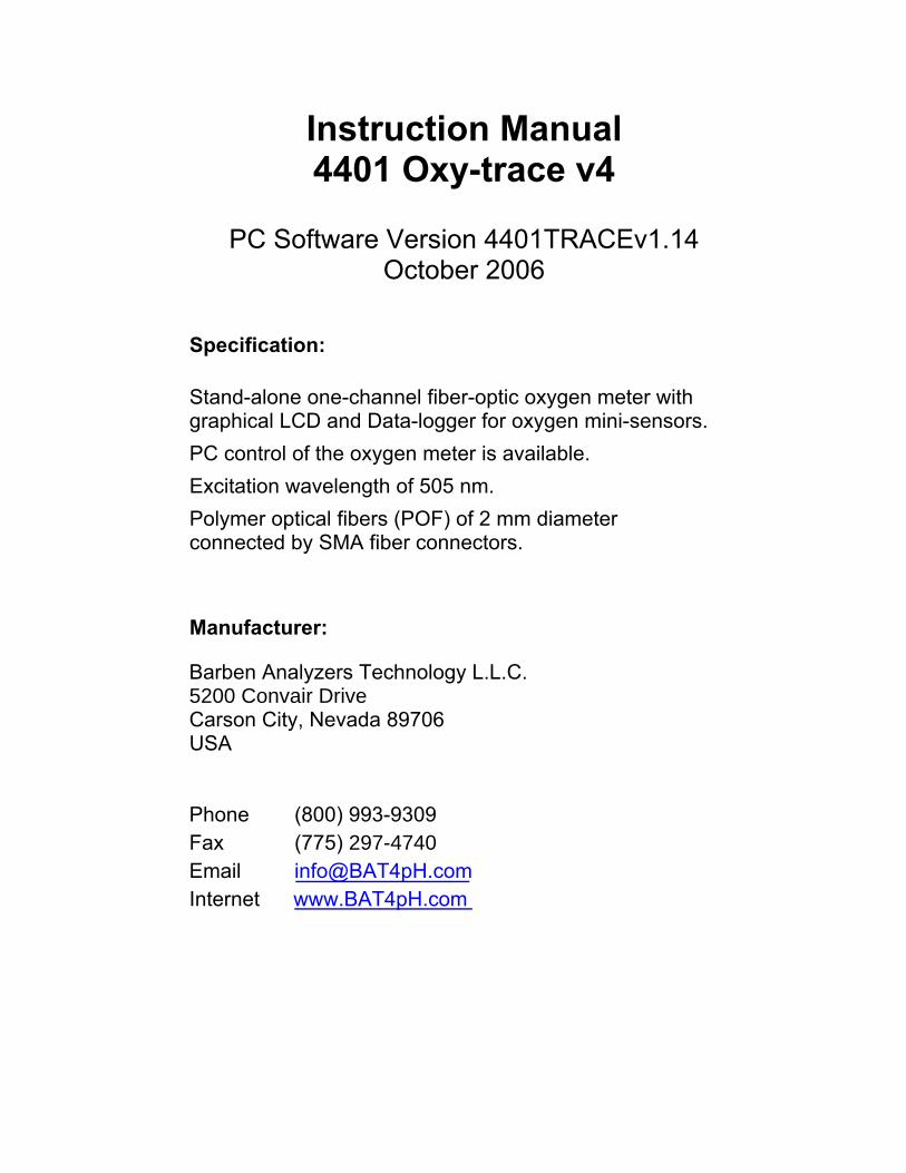
45
7.2.1 Menu Bar File Charts Display
Exit Oxygen Zoom AutoScaleY1 Undo Zoom
Phase Amplitude Clear Charts Temperature Dimensions
Print Settings
Charts Com Port Instrument Info analog output analog input LED Intensity Sensor
BOS2 BOS1 BOS2
Oxygen Unit % air-saturation % oxygen hPa (mBar) Torr ppm / ppb µmol/L
File
Exit
Closes the program.
Charts
The respective charts of the measurement can be displayed (√) or hidden
Oxygen: Oxygen content in the chosen unit
Phase: Phase angle, the raw data
Amplitude: The magnitude of the sensor signal
Temperature: The measured temperature

Calibration of the BOS2 oxygen sensor
46
Display
Zoom:
AutoScaleY1 is the default setting. AutoScaleY1 means that the y-axis is scaled automatically.
Undo Zoom: The original display is recovered; see also graphical display Clear Charts: The graphs shown on the display is cleared.
Dimensions:
You can adjust the number of measurements points on the x-axis shown in the display (maximum number of points are 5000) Furthermore, you can adjust the minimum and the maximum of the y-axis. The AutoScaleY1 function is switched off.
Charts: The charts shown in the display can be printed Settings
• ComPort
The serial comport (com1 – com20) for the serial interface (RS 232) can be chosen in this window. COM 1 is the default setting. If you choose the wrong Com port, the information window ‘Connect the instrument to the PC and choose the right com-port’ does not disappear.
• Instrument Info:
Here you can find the version of the software and some important settings of the instrument. If you have a problem with the 4401 Oxy-trace v4 oxygen meter, please contact our service team and have the software and instrument information ready. To change back to the graphical window click the ‘Measure Chart’ button.

Calibration of the BOS2 oxygen sensor
47
Instrument Info
Software Info
Barben Analyzer Technology LLC
5200 Convair Drive
Carson City, Nevada 89706
Version 7

Calibration of the BOS2 oxygen sensor
48
• LED-Intensity With the current of the LED you can adjust the amount of light illuminating the sensor spot.
You can choose between an ‘Auto Adjust’ of the LED where the 4401 Oxy-trace v4 adjusts the optimal LED current itself, or you can select ‘Advanced’ where you can adjust the LED current yourself.
If you increase the LED current, the signal amplitude increases, since a higher light density illuminates the sensor spot. Auto Adjust:
To make the adjustment of the LED intensity automatically, just click the button ‘Start Auto Adjust’. Please check that the oxygen micro-sensors have been connected to the instrument.
The automatically adjustment of the LED intensity is finished when in the status window the message ‘Auto adjustment finished’ appears. Click the ‘Close’ button to confirm the settings.

Calibration of the BOS2 oxygen sensor
49
Advanced: Click the ‘Advanced’ button to change the LED current manually. Values between 10 and 100 % are possible. After clicking the ‘confirm’ button you can see the change of the amplitude in the window below.
Please note, that after changing the LED intensity you should re-calibrate the oxygen micro-sensor. A warning window points you to re-calibrate the oxygen micro-sensor.
Please note: By increasing the light intensity you increase the amplitude of the oxygen micro-sensor. This leads to smoother phase signals. However, increasing the light intensity can increase photo-bleaching, which decreases the shelf-life of your sensor. • Sensor
Before starting the measurement you have to choose the correct sensor type. To change the sensor type you have to press the ‘Sensor’ in the Menu point ‘Settings’. The following sensor types are available: BOS2: oxygen sensor measuring in both the liquid and gas phase;
Measurement range: 0-250 % air-saturation (0-50 % oxygen) Limit of detection: 0.15 % air-saturation
BOS1: trace oxygen sensor measuring in both the liquid and gas phase;
Measurement range: 0-20 % air-saturation (0-5 % oxygen) Limit of detection: 1 ppb dissolved oxygen
BOS3: trace oxygen sensor for gas phase measurements; Measurement range: 0-200 ppm (maximum 0 – 1000 ppm) gaseous oxygen Limit of detection: 0.5 ppm gaseous oxygen

Calibration of the BOS2 oxygen sensor
50
• Oxygen Unit Here you can adjust the desired oxygen unit. Tables and formulas for the calculation of different concentration scales are given in the appendix.
• Analog output Here you can choose which data are exported via the analogue outputs. The 4401 Oxy-trace v4 device has two voltage outputs and two current output channels. The desired data sources (oxygen, temperature, amplitude, phase) can be chosen via the dialog box (see figure below). All four output channels work independent on each other.
Oxygen (Max Scale): Here you can program the correlation of the 10 V/20 mA value to the exported value. e.g. 10 V can be set to 500 % air-saturation, then 1 V corresponds to 50% air-saturation e.g. 10 V can be set to 200 ppm gaseous oxygen, then 1 V corresponds to 20 ppm To change the oxygen unit you have to go to settings and oxygen unit and adjust the desired unit.
• Analog input
Here you can choose which data are imported via the analogue inputs. The 4401 Oxy-trace v4 device has two voltage input channels. The desired data sources temperature, pressure (*option) can be chosen via the dialog box (see figure below). The purpose of input channels is to compensate the o xygen value with externally measured temperature or pressure. It is useful for a measurement set-up which has originally integrated temperature and/or pressure sensor. The user has a possibility to export analogue data from external sensor into 4401 Oxy-trace via input channels. In order to initialise the input channels correctly, a proper measurement range must be set. Once set, the input voltage is used for oxygen calculation correction. Note 1: “Higher value” is the input voltage upper limit, and is equal to 10V for 4401 Oxy-trace v4. I.E.: If
the input signal of 10V corresponds to temperature of 60°C, one should set the value in the higher value control window to 60.

Calibration of the BOS2 oxygen sensor
51
Note 2: “Lower value” is the input voltage lower limit, and is equal to 0V for 4401 Oxy-trace v4. I.E.: If the
input signal of 0V corresponds to temperature of 10°C, one should set the value in the lower value control window to 10.
Example 1: Using the values given in note 1 and 2, the temperature correction upon the input voltage is: By input voltage = 5V, the imported temperature will be 35°C By input voltage = 7.5V, the imported temperature will be 47.5°C Example 2: Suppose that input voltage of 0V 500hPa, and 10V 2000 hPa. By input voltage = 3.5V, the imported pressure will be 1025 hPa By input voltage = 5V, the imported pressure will be 1250 hPa By input voltage = 7,5V, the imported pressure will be 1625 hPa
7.2.2 Control Bar Numerical display
The actual oxygen content in the chosen unit (here % air-saturation) is displayed in the oxygen window. Tables and formulas for the calculation of different concentration scales are given in the appendix. Temperature measurement: The actual temperature value of the sample (in the case of temperature compensated measurements) is displayed in the temperature window. If measurement is performed without temperature compensation, the manual inserted temperature is displayed with the hint that temperature measurement is off–line.

Calibration of the BOS2 oxygen sensor
52

Calibration of the BOS2 oxygen sensor
53
Control buttons: The way to start a measurement is
(A) Calibration of the mini-sensor with the Calibration Assistant (B) Start Measurement with measurement Assistant (C) Readout Data-logger
(A) Calibration: The calibration assistant is opened (see chapter 7, Calibration of Oxygen-Sensitive Mini-sensors);
(B) Measurement: By clicking ‘Start Measurement’ the measurement assistant opens to enter the measurement settings. If you haven't performed sensor calibration yet the following window appears
If you want to measure with the last sensor calibration - you can find the ‘ date of the last calibration’ in the window - click the ‘ Continue’ button. To obtain reliable results we strongly recommend performing a sensor calibration before measurement by clicking the ‘ New calibration’ item when connecting a new sensor.
Follow the instructions given in chapter 7 to calibrate the respective mini-sensor.
To leave this menu click the ‘Cancel’ button.
If you have already performed sensor calibration, the measuring assistant will be opened.
In this window you can choose the measurement settings:

Calibration of the BOS2 oxygen sensor
54
In the ‘Sampling Rate’ window you can select the desired measurement mode with a drop-down menu.
By clicking the drop down menu you can choose from ‘ 1s’ to the ‘ 60 min’ mode where each hour a measuring point is recorded.
Please note: The sensor shelf life can be increased using a slower measuring mode since the effect of photo-bleaching is reduced. The illumination light is switched off between sampling. A further advantage using a high measuring mode is that huge amounts of data for long-time measurement can be avoided.
Oxygen Unit
With this drop down menu, you can adjust the desired oxygen unit. Tables and formulas for the calculation of different concentration scales are given in the appendix.
Temperature compensated oxygen measurements If you want to measure with temperature compensation, click the ’on’ button. Please ensure that the temperature sensor Pt 1000 is connected to the 4401 Oxy-trace v4, before you click the ‘ Start’ button to continue. The window where you can enter the temperature manually is disabled.

Calibration of the BOS2 oxygen sensor
55
If you want to measure without temperature compensation, choose the ’ off’ button. Please enter the temperature of your measurement sample manually. Click the ’Start’ button to start the measurement.
External Temperature compensation If analogue input channels are already configured (see chapter Analog Inputs) one can activate temperature compensation by mean of externally imported value. Here the external channel 1 or 2 can be easily selected.
NOTE: Before starting external temperature compensation it is useful to check the quality of electrical signals. This can be done when 4401 Oxy-trace v4 is NOT in “PC MODE”. By entering “Diag&Test/Analog In” submenu the input voltage can be controlled directly on the LCD.
Logging Setup:
To start the measurement without logging data click ‘Measure’ in the Logging setup and the ‘ Start’ button.
To store the data of your measurement click in the ‘Logging Setup’ the ‘Measure & Log’ item and click the button ‘Choose File’. Here you can select the location where you want to store the data. Choose as file extension *.txt. Click the ’speichern’ (SAVE) button to confirm your settings.

Calibration of the BOS2 oxygen sensor
56
You can enter a measurement description in the text field ‘ File description’ which is stored in the ASCII File. To start the measurement, click the ‘Start’ button.
In the Information windows ’Sampling Rate’ you can find the adjusted sampling rate. To be sure whether you perform a measurement with or without logging the data, the ‘ Logging Status’ window displays whether the actual measurement is stored to a file (logging) or not (no logging);
Stop Measurement The measurement is ended by a left click on the ’stop’ button in the control bar.
(C) Readout Data-logger Look at chapter 6.5 for this function and for the download from stored data in the oxygen instrument!
Warning Lights: At the right bottom of the window you can find the amplitude, phase angle and three warning lights. The warning lights are explained below:
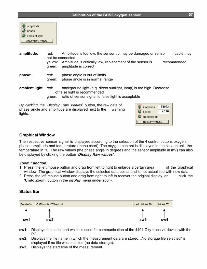
Calibration of the BOS2 oxygen sensor
57
amplitude: red: Amplitude is too low, the sensor tip may be damaged or sensor cable may not be connected
yellow: Amplitude is critically low, replacement of the sensor is recommended green: amplitude is correct phase: red: phase angle is out of limits green: phase angle is in normal range ambient light: red: background light (e.g. direct sunlight, lamp) is too high. Decrease
of false light is recommended green: ratio of sensor signal to false light is acceptable By clicking the ‘Display Raw Values’ button, the raw data of phase angle and amplitude are displayed next to the warning lights.
Graphical Window The respective sensor signal is displayed according to the selection of the 4 control buttons oxygen, phase, amplitude and temperature (menu chart). The oxy gen content is displayed in the chosen unit, the temperature in °C. The raw values (the phase angle in degrees and the sensor amplitude in mV) can also be displayed by clicking the button ‘Display Raw values’. Zoom Function: 1. Press the left mouse button and drag from left to right to enlarge a certain area of the graphical
window. The graphical window displays the selected data points and is not actualized with new data. 2. Press the left mouse button and drag from right to left to recover the original display, or click the
‘Undo Zoom’ button in the display menu under zoom.
Status Bar
sw1: Displays the serial port which is used for communication of the 4401 Oxy-trace v4 device with the
PC sw2: Displays the file name in which the measurement data are stored. „No storage file selected“ is
displayed if no file was selected (no data storage). sw3: Displays the start time of the measurement
sw1 sw2 sw3 sw4

Calibration of the BOS2 oxygen sensor
58
sw4: Displays the actual time 7.3 Error Codes The error value is binary coded. It means each bit corresponds to one specific error or warning. The summary of error bits is given below:
bit 0 = ADC overflow bit 1 = Ambient light bit 2 = no oxygen sensor bit 3 = no temperature sensor bit 4 = current output 1 open loop error bit 5 = current output 2 open loop error bit 6 = overheat bit 7 = system restart
Decoding example
If Error value received from a device is 10 then a following error has occurred:
Decimal 10 = Binary 00001010
Here bit1 ambient light and bit3 no temperature sensor are “1”. This error code would appear if there was too much of ambient light (sun light illuminating the sensor) and the temperature sensor PT1000 is not connected to the device.
7.4 Subsequent Data Handling In the head of the ASCII file, you find the description of your measurement which you have entered by storing the file. Below you find the ‘ instrument info’ containing the data of the complete calibration routine and some more important settings of the instrument and firmware. The ‘software info’ below contains the version number of the 4401 Oxy-trace v4 software, date and time of the performed measurement. If there is a problem with the 4401 Oxy-trace v4 oxygen meter, please contact our service team and have the software and instrument information ready. Below, you find the ‘ measure mode settings’ containing the dynamic averaging, and the measuring mode.
The following rows, separated by semicolons, list the measuring data. The first two rows contain the date and time, the third the log-time in minutes, the fourth the oxygen content in the chosen unit. The raw data - phase angle in [°] and the amplitude in [mV] - are stored in the fifth and sixth row, respectively. The seventh row contains the temperature in °C measured by PT1000 temperature sensor. Raw data can be used for user defined recalculations according to the formulas and tables listed in the appendix. In the last row possible error codes are listed.
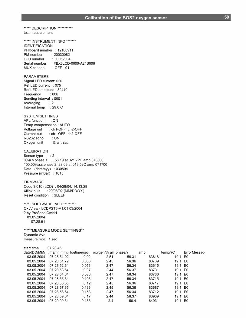
Calibration of the BOS2 oxygen sensor
59
***** DESCRIPTION ***********test measurement
***** INSTRUMENT INFO *******IDENTIFICATIONPHIboard number : 12100911PM number : 20030082LCD number : 00062004Serial number : FBX3LCD-0000-A24S006MUX channel : OFF - 01
PARAMETERSSignal LED current: 020Ref LED current : 075Ref LED amplitude : 82440Frequency : 006Sending interval : 0001Averaging : 2Internal temp : 29.6 C
SYSTEM SETTINGSAPL function : ONTemp compensation : AUTOVoltage out : ch1-OFF ch2-OFFCurrent out : ch1-OFF ch2-OFFRS232 echo : ONOxygen unit : % air. sat.
CALIBRATIONSensor type : 20%a.s.phase 1 : 58.19 at 021.7?C amp 078300100.00%a.s.phase 2: 28.09 at 019.5?C amp 071700Date (ddmmyy) : 030504Pressure (mBar) : 1015
FIRMWARECode 3.010 (LCD) : 04/28/04, 14:13:28Xilinx built : 20/08/02 (MM/DD/YY)Reset condition : SLEEP ***** SOFTWARE INFO *********OxyView - LCDPST3-V1.01 03/2004? by PreSens GmbH
03.05.200407:28:51
******MEASURE MODE SETTINGS**Dynamic Aver 1measure mod 1 sec
start time 07:28:46 date(DD/MM/Y time/hh:mm:s logtime/sec oxygen/% air phase/? amp temp/?C ErrorMessage
03.05.2004 07:28:51:02 0.02 2.51 56.31 83616 19.1 E003.05.2004 07:28:51:79 0.036 2.45 56.36 83739 19.1 E003.05.2004 07:28:52:64 0.053 2.47 56.34 83615 19.1 E003.05.2004 07:28:53:64 0.07 2.44 56.37 83731 19.1 E003.05.2004 07:28:54:64 0.086 2.47 56.34 83736 19.1 E003.05.2004 07:28:55:64 0.103 2.47 56.34 83715 19.1 E003.05.2004 07:28:56:65 0.12 2.45 56.36 83717 19.1 E003.05.2004 07:28:57:65 0.136 2.45 56.36 83687 19.1 E003.05.2004 07:28:58:64 0.153 2.47 56.34 83712 19.1 E003.05.2004 07:28:59:64 0.17 2.44 56.37 83939 19.1 E003.05.2004 07:29:00:64 0.186 2.4 56.4 84031 19.1 E0

Calibration of the BOS2 oxygen sensor
60
8. Calibration of BOS2 Oxygen-Sensitive Fiber-Optic Mini-sensors
This chapter describes the calibration of oxygen mini-sensors containing a BOS2 oxygen-sensitive coating (measuring range 0 – 50 % oxygen). For any question concerning the calibration, please contact our service team. Before starting the calibration procedure, please ensure that the sensor type BOS2 is adjusted. This can be done in the menu point ‘Settings’ under ’Sensor’. 8.1 Preparation of the Calibration Standards Calibration of oxygen mini-sensors is performed using a conventional two-point calibration in oxygen-free environment (cal 0) and water-vapor saturated air or air-saturated water (cal 100). Preparation of calibration solution 0 (oxygen-free water): 1. Add one gram sodium sulfite (Na2SO3) to the vessel and label it cal 0;
2. Dissolve Na2SO3 in 100 mL water. Water becomes oxygen-free due to a chemical reaction of oxygen with Na 2SO3. Additional oxygen, diffusing from air into the water, is removed by surplus of Na2SO3.
3. Close the vessel with a screw top and shake it for approximately one minute to dissolve Na 2SO3 and to ensure that water is oxygen-free.
Close the vessel after calibration with a screw top to minimize oxygen contamination. The shelf life of cal 0 is about 24 hours provided that the vessel has been closed with the screw top.
Alternatively, nitrogen 5.0 can be used to adjust the oxygen-free environment.
Preparation of calibration standard 100 (water-vapor saturated air) 1. Place wet cotton wool in the vessel with the label cal 100.
2. Drill two holes for inserting the mini-sensor and the temperature sensor in the screw top and close the vessel.
3. Wait about 2 minutes to ensure that air is water-vapor saturated
Preparation of calibration solution 100 (air-saturated water)
1. Add 100 mL water to a suitable vessel and label it cal 100.
2. To obtain air-saturated water, blow air into the water using an air-pump with a glass-frit (airstone), creating a multitude of small air bubbles, while stirring the solution.
3. After 20 minutes, switch of the air-pump and stir the solution for further 10 minutes to ensure that water is not supersaturated.

Calibration of the BOS2 oxygen sensor
61
8.2 Mounting the Oxygen-Sensitive Mini-sensor and Sensor Spots 8.2.1 Oxygen Dipping Probe 1. Remove the oxygen sensor carefully from the protective cover.
2. Carefully remove the protective plastic cap covering the oxygen-sensitive sensor spot.
3. Fix the oxygen sensor with a clip to a laboratory support or a similar stable construction.
4. Remove the protective cap from the male fiber plug and connect it to the SMA-plug of the 4401 Oxy-trace v4 device. The safety nut must be carefully attached while turning slightly clockwise.
8.2.2. Oxygen flow through cell (FTC-BOS2-xx) 1. Remove the flow-through cell oxygen sensor carefully from the protective cover. The oxygen-
sensitive material is immobilized to a glass tube which is located in a T-connector with two female Luer-Lock adapters. The glass tube is tightened with a Viton seal and two male Luer-Lock connectors fix the glass tube in the T-connector. On request the seal can also be made from silicone.
Don't remove the two male Luer-Lock adapters from the T-connector. You may loose the Viton seal and the glass tube may be dislocated.
2. Fix the male Luer-Lock adapter with the integrated 2 mm POF (polymer optical fiber) to the Luer T-connector and ensure that the fiber is located close to the glass tube.
male Luer Lock connector
male Luer Lock connector
glass tube withintegrated oxygen sensor
male Luer Lock connectorcontaining a 2 mm POF located
at the glass tube
viton seal viton seal

Calibration of the BOS2 oxygen sensor
62
3. Fix the flow-through cell with a clip to a laboratory support or a similar stable construction.
4. Connect the two male Luer-Lock connectors with the tubing of your flow-through system.
5. Remove the protective cap from the male fiber plug and connect it to the SMA-plug of the 4401 Oxy-trace v4 device. The safety nut must be carefully attached while turning slightly clockwise.
8.2.3 Oxygen-Sensitive Spot (SP-BOS2-xx) 1. Remove the oxygen-sensitive foil carefully from the protective cover.
2. Glue small spots of the oxygen-sensitive foil into the desired glass vessel.
Please note: Be sure to glue the sensor spots onto your vessel with the proper side! The sensor support (polyester foil or glass) on which the sensor is spotted (identifiable by its faint reflection) is glued to the vessel, while the sensor itself (black side in case of optically isolated and red side in case of spots without optical isolation) must look toward the sample. The figure below shows how the (highly enlarged) sensor spot must be glued to the vessel. For gluing the spots a very small amount of the glue (a small drop) is sufficient. Try to avoid that the silicone glue comes in contact with the black sensor layer. This would lead to an increase in the response time. Since the response time of the sensor is dependent from the diffusion rate of oxygen through the sensor layer, additional silicone layer will slow down the response time. However, the sensor layer is not affected by the glue.
Sensor spot (SP) glued into a vessel (no optical isolation).
Optical isolated sensor spot (SP) glued into a vessel.
Sensor Support
Sensor
Optical isolation
Sample
Vessel bottom

Calibration of the BOS2 oxygen sensor
63
3. Remove the protective cap from the male fiber plugs of the delivered fiber cable and connect it to the SMA-plugs of the 4401 Oxy-trace v4 device and the holding device. The safety nut must be carefully attached while turning slightly clockwise.
8.3 Calibration without Automatic Temperature Compensation Using the software, you can choose whether to perfo rm the measurement and calibration with or without temperature compensation. If you want to perform the calibration without automatic temperature compensation, please ensure that the delivered temperature sensor PT 1000 is not connected to the 4401 Oxy-trace v4. Please note: Calibration without temperature compensation only makes sense if there is no temperature change during the calibration of the oxygen sensor. Besides, it must be ensured that the temperature during later measurement is constant and already known. However, the temperatures during the measurement and the calibration process are allowed to be different. 1. Connect the 4401 Oxy-trace v4 via the RS232 cable to your computer.
2. Switch on the 4401 Oxy-trace v4 and connect the oxygen mini-sensor as shown in Chapter "Mounting the Oxygen-Sensitive Mini-sensor and Sensor Spots“.
3. Start the 4401 Oxy-trace software on your computer and click the calibration menu item.
4. Select the calibration routine: ‘calibrate without temp sensor‘and click the ‘cal.’ button
5. Enter the actual atmospheric pressure and the temperature of the calibration standards. The atmospheric pressure of the calibration is needed to convert the oxygen unit % air-saturation into partial pressure units (hPa, Torr) or concentrations units (mg/L µmol/L). Please note, that changes in the actual atmospheric pressure have no effect on the partial pressure units (hPa, Torr) and concentrations units (mg/L, µmol/L) but the oxygen units % air-saturation and % oxygen-saturation have to be corrected for air pressure changes.

Calibration of the BOS2 oxygen sensor
64
6a. DP-BOS2-xx
Place the calibration standard 100 ( cal 100), containing wet cotton wool, underneath the oxygen mini-sensor. The vessel with the label " cal 100" has to be closed with the screw top containing the two holes.
Insert the plastic fiber carefully through one of the holes without touching the oxygen-sensitive spot until it is about 3 cm deep inside the vessel. Make sure that the plastic fiber with its sensor spot cannot touch the vessel and the cotton wool.

Calibration of the BOS2 oxygen sensor
65
6b. FTC-BOS2-xx Connect one plastic tubing with a syringe, the other dip into the vessel containing the calibration solution 100, cal 100. Fill the syringe slowly with calibration solution 100. Please ensure that there are no air-bubbles located in the glass tube of the flow-through cell.
6c. SP-BOS2-xx Place the calibration solution 100 (cal 100), air-saturated water (or water-vapor saturated air), into the vessel equipped with the sensor spot. To minimize the response time, slightly stir the solution. Please ensure that the cal 100 solution completely covers the sensor oxygen-sensitive spot.
7. Wait about 3 minutes until the phase angle is constant (the variation of the phase angle should be smaller than ± 0.1°) and press the ‘Store current value’ button to store the 100% air-sat. and temp. at 100% values. A message window opens and informs you that you will overwrite the existing calibration values. Click the ‘Continue’ button to store the new calibration data.
8. Now you have to record the second calibration value, oxygen-free water (cal 0). 8a) DP-BOS2-xx Place the vessel with the label "cal 0" underneath the oxygen mini-sensor.
Insert the plastic fiber about 2 cm deep into the cal 0 solution. Make sure that the plastic fiber with its sensor spot cannot touch the vessel. To increase the response time, stir the cal 0 solution. As alternative for adjusting an oxygen free environment, the chamber containing the oxygen dipping probe can be purged with pure nitrogen.
8b) FTC-BOS2-xx
To record the second calibration value, oxygen-free water, dip the plastic tubing into the vessel containing the calibration solution 0, cal 0 and fill the syringe slowly with it. Please ensure that there are no air-bubbles located in the glass tube of the flow-through cell.
As alternative for adjusting an oxygen free environment, the flow-through cell can be purged with pure nitrogen.

Calibration of the BOS2 oxygen sensor
66
8c) SP-BOS2-xx Remove the cal 100 solution from the vessel and fill it with the calibration standard 0, cal 0. To
minimize the response time, slightly stir the solution. Please note, vigorous stirring can lead to an oxygen contamination of the cal 0 solution.
As alternative for adjusting an oxygen free environment, the chamber containing the oxygen dipping probe can be purged with pure nitrogen.
9) Wait about 3 minutes until the phase angle is constant (the variation of the phase angle should be smaller than ± 0.05°) and click the ‘Store current value’ button to store the 0% air-sat. and temp. at 0% values
10. Now, calibration is complete. Confirm the calibration values by clicking the ‘ Finish’ button and click
the ‘Continue‘ button in the following message window to store the new calibration data.
11. Wash the oxygen mini-sensor or oxygen-sensitive spot with distilled water to clean it from sodium sulfite. Exchange the calibration solution 0 with an identical vessel filled with distilled water. Make sure, not to touch the sensor spot.
12. Protect the sensor spot with the delivered protective plastic cover and store it in the dark until just before measurement.

Calibration of the BOS2 oxygen sensor
67
8.4 Calibration with Automatic Temperature Compensation 1. Connect the 4401 Oxy-trace v4 via the RS232 cable to your computer.
2. To perform temperature compensated measurement, connect the temperature sensor Pt 1000 to the 4-pin connector in front of the 4401 Oxy-trace v4. Fix the temperature sensor and make sure that neither the temperature sensor nor its cable can touch the mini-sensor.
3. Switch on the 4401 Oxy-trace v4 and connect the oxygen mini-sensor as shown in Chapter “Mounting the Oxygen-Sensitive Mini-sensor and Sensor Spot”.
4. Start the 4401 Oxy-trace software on your computer and click the calibration menu item.
5. Select the calibration routine: ‘calibrate with temperature sensor’ by clicking the ‘cal.’ button.
6. Continue with the calibration procedure as described in the chapter ‘ Calibration without Automatic Temperature Compensation’. Ensure that the temperature sensor is also inserted into the respective calibration vessel. The variation of the phase angle and the temperature exposed to the respective calibration standard should be smaller than ± 0.1° and 0.1 °C, respectively

Calibration of the BOS2 oxygen sensor
68
8.5 User defined Calibration A manual calibration should be applied, if you don't want to calibrate your sensor again. However, this is only possible if you already know the calibration values of the special sensor. 1. Connect the 4401 Oxy-trace v4 via the RS232 cable to your computer.
2. Switch on the 4401 Oxy-trace v4 oxygen meter
3. Start the 4401 Oxy-trace v4 software on your computer and click the Calibration menu item.
4. Select the calibration routine ‘calibrate manually’ and click the manual button
5. Enter the atmospheric pressure at which calibration was performed (not the actual one) and the respective calibration values 0% air-sat., temp. at 0% and 100 % air-sat., temp. at 100%.
6. Now, user-defined calibration is complete. Confirm the calibration values by clicking the Finish
button. A message window opens and informs you that you will overwrite the existing calibration values. Click the ‘Continue’ button to store the new calibration data.

Calibration of the BOS2 oxygen sensor
69

Calibration of the trace oxygen sensor BOS1
70
Calibration of Trace Oxygen Sensor BOS1
This chapter describes the calibration of trace oxygen mini-sensors containing a BOS1 oxygen-sensitive coating (measuring range 0 – 20 % air-saturation). For any question, please contact our service team. Before starting the calibration procedure, please ensure that the sensor type BOS1 is adjusted. This can be done in the menu point ‘Settings’ under ’Sensor’.
Preparation of the Calibration Standards Calibration of oxygen mini-sensors is performed using a conventional two-point calibration a nitrogen-saturated atmosphere (nitrogen 5.0) (cal 0) and a second calibration value, optimally in the range between 5 and 10 % air-saturation (ca. 1 and 2 % pure oxygen). The second calibration value may be adjusted via a gas mixing device or with a commercially available test gas. Please note: If there is no possibility to use a gas mixing device to adjust the second calibration value or to build a suitable calibration chamber, an “User-defined calibration” (see chapter 7.1.5) where you have to enter the two calibration values obtained from the Barben Analyzer inspection sheet is strongly recommended. Mounting the Trace Oxygen-Sensitive Mini-sensor and Sensor Spots Trace Oxygen Dipping Probe (DP-BOS1-xx) 1. Remove the oxygen sensor carefully from the protective cover.
2. Carefully remove the protective plastic cap covering the oxygen-sensitive sensor spot.
3. Fix the oxygen sensor with a clip to a laboratory support or a similar stable construction.
4. Remove the protective cap from the male fiber plug and connect it to the SMA-plug of the 4401 Oxy-trace v4 device. The safety nut must be carefully attached while turning slightly clockwise.
Trace Oxygen Flow Through Cell (FTC-BOS1-xx) 1. Remove the flow-through cell oxygen sensor carefully from the protective cover. The oxygen-
sensitive material is immobilized to a glass tube which is located in a T-connector with two female Luer-Lock adapters. The glass tube is tightened with a Viton seal and two male Luer-Lock connectors fix the glass tube in the T-connector. On request the seal can also be made from silicone.

Calibration of the trace oxygen sensor BOS1
71
Don't remove the two male Luer-Lock adapters from the T-connector. You may loose the Viton seal and the glass tube may be dislocated.
2. Fix the male Luer-Lock adapter with the integrated 2 mm POF (polymer optical fiber) to the Luer T-connector and ensure that the fiber is located close to the glass tube.
3. Fix the flow-through cell with a clip to a laboratory support or a similar stable construction.
4. Connect the two male Luer-Lock connectors with the tubing of your flow-through system.
5. Remove the protective cap from the male fiber plug and connect it to the SMA-plug of the 4401 Oxy-trace v4 device. The safety nut must be carefully attached while turning slightly clockwise.
male Luer Lock connector
male Luer Lock connector
glass tube withintegrated oxygen sensor
male Luer Lock connectorcontaining a 2 mm POF located
at the glass tube
viton seal viton seal

Calibration of the trace oxygen sensor BOS1
72
Trace Oxygen-Sensitive Spot (SP-BOS1-xx) 1. Remove the oxygen-sensitive foil carefully from the protective cover.
2. Glue small spots of the oxygen-sensitive foil into the desired glass vessel.
Please note: Be sure to glue the sensor spots onto your vessel with the proper side! The sensor support (polyester foil or glass) on which the sensor is spotted (identifiable by its faint reflection) is glued to the vessel, while the sensor itself (black side in case of optically isolated and red side in case of spots without optical isolation) must look toward the sample. The figure below shows how the (highly enlarged) sensor spot must be glued to the vessel. For gluing the spots a very small amount of the glue (a small drop) is sufficient. Try to avoid that the silicone glue comes in contact with the black sensor layer. This would lead to an increase in the response time. Since the response time of the sensor is dependent from the diffusion rate of oxygen through the sensor layer, additional silicone layer will slow down the response time. However, the sensor layer is not affected by the glue.
Sensor spot (SP) glued into a vessel (no optical isolation).
Optical isolated sensor spot (SP) glued into a vessel.
3. Remove the protective cap from the male fiber plugs of the delivered fiber cable and connect it to the SMA-plugs of the 4401 Oxy-trace v4 device and the holding device. The safety nut must be carefully attached while turning slightly clockwise.
Sensor Support
Sensor
Optical isolation
Sample
Vessel bottom

Calibration of the trace oxygen sensor BOS1
73
Calibration without Automatic Temperature Compensation Using the software, you can choose whether to perfo rm the measurement and calibration with or without temperature compensation. If you want to perform the calibration without automatic temperature compensation, please ensure that the delivered temperature sensor PT 100 is not connected to the 4401 Oxy-trace v4 oxygen meter. Please note: Calibration without temperature compensation only makes sense if there is no temperature change during the calibration of the oxygen sensor. Besides, it must be ensured that the temperature during later measurement is constant and already known. However, the temperatures during the measurement and the calibration process are allowed to be different. 1. Connect the 4401 Oxy-trace v4 via the RS232 cable to your computer.
2. Switch on the 4401 Oxy-trace v4 and connect the oxygen mini-sensor as shown in Chapter "Mounting the Trace Oxygen-Sensitive Mini-sensor and Sensor Spots“.
3. Start the 4401 Oxy-trace v4 software on your computer and click the calibration menu item.
4. Select the calibration routine: ‘calibrate without temp sensor’ and click the ‘cal.’ button
5. Enter the actual atmospheric pressure and the temperature of the calibration standards ( temp. at 0%, temp at 2nd point). The atmospheric pressure of the calibration is needed to convert the oxygen unit % air-saturation in partial pressure units (hPa, Torr) or concentrations units (mg/L µmol/L). Please note, that changes in the actual atmospheric pressure have no effect on the partial pressure units (hPa, Torr) and concentrations units (mg/L, µmol/L) but the oxygen units % air-saturation and % oxygen-saturation have to be corrected for air pressure changes.
6. Place the trace oxygen sensor (DP-BOS1-xx, FTC-BOS1-xx, SP-BOS1-xx) into the adjusted gas atmosphere of the second calibration standard in your calibration chamber.
Please ensure, not to create an overpressure or to contaminate your calibration chamber with air. The oxygen content of the second calibration value should be optimally between 5 and 10 % air-saturation which correlate to about 1 and 2 % pure oxygen, respectively. Enter the adjusted 2nd point in % air-saturation (e.g. 2 % oxygen = 2/20.95*100 % air-sat. = 9.55 % air-sat.) in the calibration window.
7. Wait about 5 minutes until the phase angle is constant (the variation of the phase angle should be smaller than ± 0.1°) and press the ‘ Store current value’ button to store the 2nd point and temp. at 2nd point values. A message window opens and informs you that you w ill overwrite the existing calibration values. Click the ‘Continue’ button to store the new calibration data.

Calibration of the trace oxygen sensor BOS1
74
7. Now you have to record the cal 0 calibration value in a nitrogen-saturate atmosphere. Please use
pure nitrogen 5.0.
Place the trace oxygen sensor (DP-BOS1-xx, FTC -BOS1-xx, SP-BOS1-xx) into the adjusted gas atmosphere (pure nitrogen 5.0) in your calibration chamber.
Please ensure, not to create an overpressure and that no traces of oxygen can diffuse into your measuring system. Wait about 5 minutes until the phase angle is constant (the variation of the phase angle should be smaller than ± 0.1°) and press the ‘Store current value’ button to store the 0% air-sat. and temp. at 0% values. A message window opens and informs you that you w ill overwrite the existing calibration values. Click the ‘Continue’ button to store the new calibration data.
9. Now, calibration is complete. Confirm the calibration values by clicking the ‘Finish’ button.
10. Protect the sensor spot with the delivered protective plastic cover and don't remove it again until just before measurement.
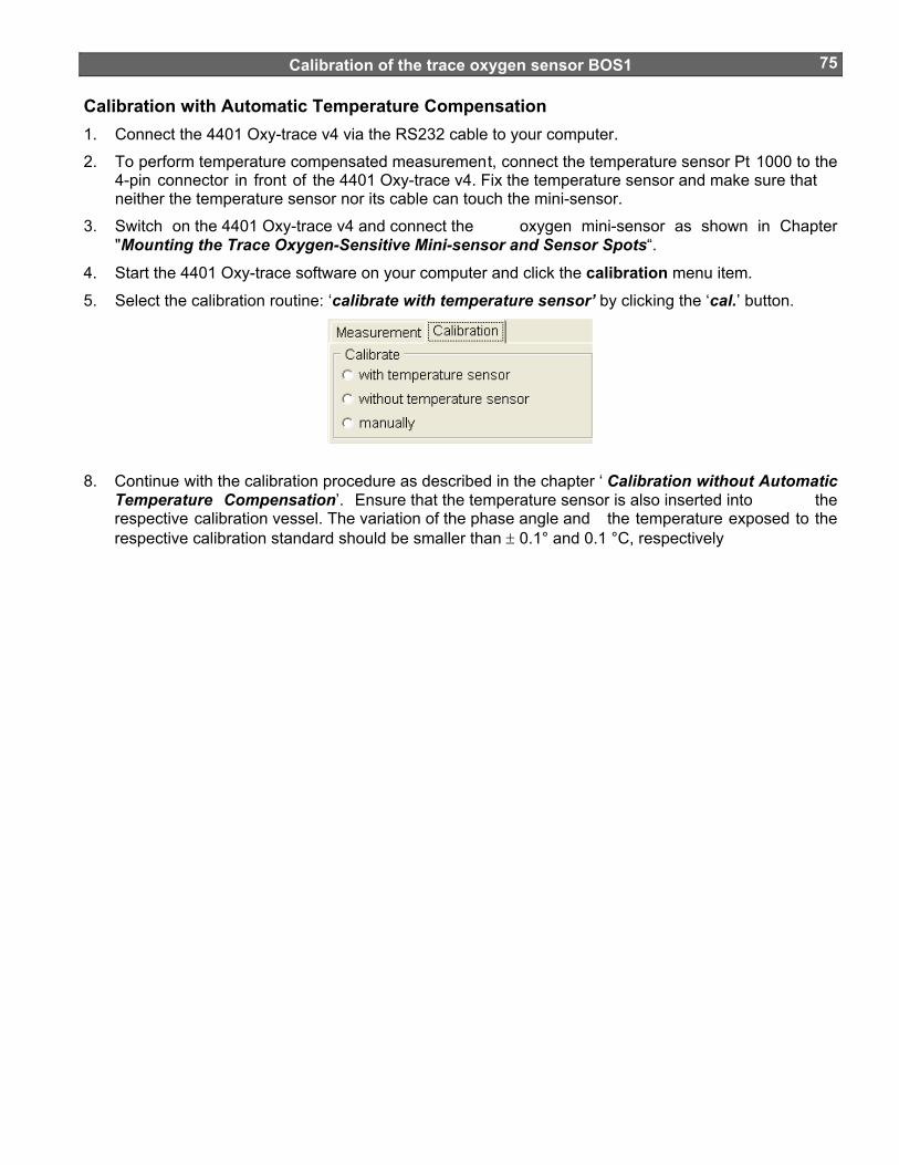
Calibration of the trace oxygen sensor BOS1
75
Calibration with Automatic Temperature Compensation 1. Connect the 4401 Oxy-trace v4 via the RS232 cable to your computer.
2. To perform temperature compensated measurement, connect the temperature sensor Pt 1000 to the 4-pin connector in front of the 4401 Oxy-trace v4. Fix the temperature sensor and make sure that neither the temperature sensor nor its cable can touch the mini-sensor.
3. Switch on the 4401 Oxy-trace v4 and connect the oxygen mini-sensor as shown in Chapter "Mounting the Trace Oxygen-Sensitive Mini-sensor and Sensor Spots“.
4. Start the 4401 Oxy-trace software on your computer and click the calibration menu item.
5. Select the calibration routine: ‘calibrate with temperature sensor’ by clicking the ‘cal.’ button.
8. Continue with the calibration procedure as described in the chapter ‘ Calibration without Automatic Temperature Compensation’. Ensure that the temperature sensor is also inserted into the respective calibration vessel. The variation of the phase angle and the temperature exposed to the respective calibration standard should be smaller than ± 0.1° and 0.1 °C, respectively

Calibration of the trace oxygen sensor BOS1
76
User defined Calibration A manual calibration should be applied, if you don't want to calibrate your sensor again. However, this is only possible if you already know the calibration values of the special sensor. 1. Connect the 4401 Oxy-trace v4 via the RS232 cable to your computer.
2. Switch on the 4401 Oxy-trace v4 oxygen meter
3. Start the 4401 Oxy-trace v4 software on your computer and click the Calibration menu item.
4. Select the calibration routine ‘calibrate manually’ and click the manual button
5. Enter the atmospheric pressure at which calibration was performed (not the actual one) and the
respective calibration values phase, temp. at 0% air-sat. and phase, temp. at 2nd point.
6. Now, user-defined calibration is complete. Confirm the calibration values by clicking the Finish
button. A message window opens and informs you that you will overwrite the existing calibration values. Click the ‘Continue’ button to store the new calibration data.

Calibration of Trace Oxygen Sensor BOS3
77
Calibration of Trace Oxygen Sensor BOS3
This chapter describes the calibration of trace oxygen mini-sensors containing a BOS3 oxygen-sensitive coating (measuring range 0 – 200 ppm). Calibration of oxygen mini-sensors is performed using a conventional two-point calibration in an oxygen-free environment ( e.g. a nitrogen-saturated atmosphere (cal 0)) and a second calibration value, optimally in the range of 10-50 ppm oxygen in nitrogen. Before starting the calibration procedure, please ensure that the sensor type BOS3 is adjusted. This can be done in the menu point ‘Settings’ under ’Sensor’. For any question, please contact our service team.
Mounting the Trace Oxygen-Sensitive Mini-sensors Trace Oxygen Dipping probe (DP-BOS3-xx) 1. Remove the oxygen sensor carefully from the protective cover.
2. Carefully remove the protective plastic cap covering the oxygen-sensitive sensor spot.
3. Fix the oxygen sensor with a clip to a laboratory support or a similar stable construction.
4. Remove the protective cap from the male fiber plug and connect it to the SMA-plug of the 4401 Oxy-trace v4 device. The safety nut must be carefully attached while turning slightly clockwise.
Trace Oxygen Flow-Through Cell (FTC-BOS3-xx) 1. Remove the flow-through cell oxygen sensor carefully from the protective cover. The oxygen-
sensitive material is immobilized to a glass tube which is located in a T-connector with two female Luer-Lock adapters. The glass tube is tightened with a Viton seal and two male Luer-Lock connectors fix the glass tube in the T-connector. On request the seal can also be out of silicone.
Don't remove the two male Luer-Lock adapters from the T-connector. You may loose the Viton seal and the glass tube may be dislocated.

Calibration of Trace Oxygen Sensor BOS3
78
2. Fix the male Luer-Lock adapter with the integrated 2 mm POF (polymer optical fiber) to the Luer T-connector and ensure that the fiber is located close to the glass tube.
3. Fix the flow-through cell with a clip to a laboratory support or a similar stable construction.
4. Connect the two male Luer-Lock connectors with the tubing of your flow-through system.
5. Remove the protective cap from the male fiber plug and connect it to the SMA-plug of the 4401 Oxy-trace v4 device. The safety nut must be carefully attached while turning slightly clockwise.

Calibration of Trace Oxygen Sensor BOS3
79
Trace Oxygen-sensitive spots (SP-BOS3-xx) 1. Remove the oxygen-sensitive foil carefully from the protective cover.
2. Glue small spots of the oxygen-sensitive foil into the desired glass vessel.
Please note: Be sure to glue the sensor spots onto your vessel with the proper side! The sensor support (polyester foil or glass) on which the sensor is spotted (identifiable by its faint reflection) is glued to the vessel, while the sensor itself (black side in case of optically isolated and red side in case of spots without optical isolation) must look toward the sample. The figure below shows how the (highly enlarged) sensor spot must be glued to the vessel. For gluing the spots a very small amount of the glue (a small drop) is sufficient. Try to avoid that the silicone glue comes in contact with the black sensor layer. This would lead to an increase in the response time. Since the response time of the sensor is dependent from the diffusion rate of oxygen through the sensor layer, additional silicone layer will slow down the response time. However, the sensor layer is not affected by the glue.
Sensor spot (SP) glued into a vessel (no optical isolation).
Optical isolated sensor spot (SP) glued into a vessel.
3. Remove the protective cap from the male fiber plugs of the delivered fiber cable and connect it to the SMA-plugs of the 4401 Oxy-trace v4 device and the holding device. The safety nut must be carefully attached while turning slightly clockwise.
Sensor Support
Sensor
Optical isolation
Sample
Vessel bottom

Calibration of Trace Oxygen Sensor BOS3
80
Calibration without Automatic Temperature Compensation Using the software, you can choose whether to perform the measurement and calibration with or without temperature compensation. If you want to perform the calibration without automatic temperature compensation, please ensure that the delivered temperature sensor PT 100 is not connected to the 4401 Oxy-trace v4 oxygen meter. Please note: Calibration without temperature compensation only makes sense if there is no temperature change during the calibration of the oxygen sensor. Besides, it must be ensured that the temperature during later measurement is constant and already known. However, the temperatures during the measurement and the calibration process are allowed to be different. 1. Connect the 4401 Oxy-trace v4 via the RS232 cable to your computer.
2. Switch on the 4401 Oxy-trace v4 and connect the oxygen mini-sensor as shown in Chapter "Mounting the Trace Oxygen-Sensitive Mini-sensor“.
3. Start the 4401 Oxy-trace v4 software on your computer and click the calibration menu item.
4. Select the calibration routine: ‘calibrate without temp sensor’ and click the ‘cal.’ button
5. Enter the actual atmospheric pressure and the temperature of the calibration standards ( temp. at 0%, temp at 2nd point).
6. Place the trace oxygen sensor (DP-BOS3-xx, FTC-BOS3-xx, SP-BOS3-xx) into the adjusted gas atmosphere of the second calibration standard in your calibration chamber.
Please ensure, not to create an overpressure and ensure, that the sensor is mounted tightly and no contaminate with air or oxygen is possible. The oxygen content of the second calibration value should be in the range of 10 - 50 ppm. Enter the adjusted 2nd point in ppm gaseous oxygen in the calibration window.
7. Wait about 5 minutes until the phase angle is constant (the variation of the phase angle should be smaller than ± 0.1°) and press the ‘ Store current value’ button to store the 2nd point and temp. at 2nd point values. A message window opens and informs you that you w ill overwrite the existing calibration values. Click the ‘Continue’ button to store the new calibration data.

Calibration of Trace Oxygen Sensor BOS3
81
9. Now you have to record the cal 0 calibration value in a nitrogen-saturate atmosphere (nitrogen
5.0). Place the trace oxygen sensor (DP-BOS3-xx, FTC -BOS3-xx, SP-BOS3-xx) into the adjusted gas atmosphere (pure nitrogen 5.0) in your calibration chamber.
Please ensure, not to create an overpressure and ensure, that the sensor is mounted tightly and no contaminate with air or oxygen is possible.
Wait about 5 minutes until the phase angle is constant (the variation of the phase angle should be smaller than ± 0.1°) and press the ‘Store current value’ button to store the 0% air-sat. and temp. at 0% values. A message window opens and informs you that you w ill overwrite the existing calibration values. Click the ‘Continue’ button to store the new calibration data.
9. Now, calibration is complete. Confirm the calibration values by clicking the ‘Finish’ button.
10. Protect the sensor spot with the delivered protective plastic cover and don't remove it again until just before measurement.

Calibration of Trace Oxygen Sensor BOS3
82
Calibration with Automatic Temperature Compensation 1. Connect the 4401 Oxy-trace v4 via the RS232 cable to your computer.
2. To perform temperature compensated measurem ent, connect the temperature sensor Pt1000 to the 4-pin connector in front of the 4401 Oxy-trace v4 and carefully tighten the safety nut. Fix the temperature sensor and make sure that neither the temperature sensor nor its cable can touch the oxygen mini-sensor.
3. Switch on the 4401 Oxy-trace v4 and connect the oxygen mini-sensor as shown in Chapter "Mounting the Trace Oxygen-Sensitive Mini-sensor and Sensor Spots“.
4. Start the 4401 Oxy-trace software on your computer and click the calibration menu item.
5. Select the calibration routine: ‘calibrate with temperature sensor’ by clicking the ‘cal.’ button.
10. Continue with the calibration procedure as described in the chapter ‘ Calibration without Automatic Temperature Compensation’. Ensure that the temperature sensor is also inserted into the respective calibration vessel. The variation of the phase angle and the temperature exposed to the respective calibration standard should be smaller than ± 0.1° and 0.1 °C, respectively
User-Defined Calibration User-defined calibration should be applied, if you don't have the possibility to adjust the second calibration value via a gas mixing device or if you don’t want to calibrate your sensor again. Barben Analyzers delivers an inspection sheet with each oxygen sensor where you can find two calibration values, which you have to enter in the user-defined calibration mode. 1. Connect the 4401 Oxy-trace v4 via the RS232 cable to your computer.
2. Switch on the 4401 Oxy-trace v4 oxygen meter
3. Start the 4401 Oxy-trace v4 software on your computer and click the Calibration menu item.
4. Select the calibration routine ‘calibrate manually’ and click the manual button
5. Enter the atmospheric pressure at which calibration was performed (not the actual one) and the
respective calibration values phase, temp. at 0% air-sat. and phase, temp. at 2nd point.

Calibration of Trace Oxygen Sensor BOS3
83
6. Now, user-defined calibration is complete. Confirm the calibration values by clicking the Finish
button. A message window opens and informs you that you will overwrite the existing calibration values. Click the ‘Continue’ button to store the new calibration data.

Measurement
84
Some Advice for Correct Measurement
Calibration of the sensor is recommended before each new application. If you don't want to recalibrate a sensor, you can use the calibration values of your last measurement (see "User-Defined Calibration"). Ensure that the temperature of the sample is known and is constant during measurement, if you do not use temperature compensation. In the case of temperature-compensated measurements, the temperature sensor Pt 100 should be positioned as close as possible to the oxygen mini-sensor to avoid temperature differences. Please consult the special information on our Website www.BAT4ph.com or contact our service team if you are in any doubt. Signal drifts due to oxygen gradients Please, keep in mind, that the sensor only measures the oxygen content near its surface. In unstirred solutions occurs often an oxygen concentration gradient.
Please check if air bubbles are on the sensor tip whenever unexpected drifts, gradients or unstable measurement values occur. Critical conditions for bubbl e formations are, for example, purging with air or other gases and increasing temperature during measurement.
The formation of a bio-film during long term meas urements or the accumulation of other sample components like oil or solid substances may lead to an oxygen gradient.
Signal drifts due to temperature gradients A further source of imprecise measurement is in sufficient temperature compensation. If you use the temperature compensation, ensure that no temper ature gradients exist between the oxygen sensor and the temperature sensors. If you measure without temperature compensation, please bear in mind, that the 4401 Oxy-trace v4 only measures correctly, if the sample temperature is constant during measurement and the temperature is the same as you typed in at the beginning of the measurement. Please also refer to Chapter 12.5 "Formulas for temperature compensation". If the temperature is measured with a precision of ± 0.2 °C, there is a variation in the measuring value at 100% air-saturation of ±0.7 % air-saturation. Please choose the measurement with temperature compensation to minimize temperature gradients. Signal drift due to photo-decomposition The oxygen-sensitive material may be subject to photo-decomposition resulting in a signal drift. Photo-decomposition takes place only during illumination of the sensor tip and depends on the intensity of the excitation light. Therefore, the excitation light was minimized. Continuous illumination of a POF-BOS2 oxygen sensor over a period of 24 hours may lead to a phase drift of up to + 0.4 % air-saturation measured at 100% air-saturation at 20°C. However, this effect of photo-decomposition can even be minimized, by changi ng the measuring mode to the second or minute interval mode. In these modes, the software switches off the excitation light after recording the data point and switches it on after the interval you have chosen. Please use the interval method whenever it is possible to increase the shelf life of the micro-sensor. Sensor Drift at 0 % air-saturation (0 ppb) recording 3600, 50000 and 100000 data points. Drift per 3600 points Drift per 50000 points Drift per 100000 points BOS2 < 0.15 % air-sat. < 0.15 % air-sat. < 0.25 % air-sat. BOS1 < 1 ppb < 2 ppb < 3 ppb Drift in % air-saturation at 100% air-saturation when illuminating the oxygen sensor BOS2 for 1, 12 and 24 hours in the continuous mode.

Measurement
85
20
25
30
35
40
45
50
55
60
0 5 10 15 20 25time [h]
phas
e an
gle
[°]
100 % air-saturation
0 % air-saturation
Photo-decomposition test of BOS2, continuously illuminating the sensor membrane for 25 hours Signal drift due to too much ambient light
A source of error is the detector overload due to too much ambient light. A detector overload can be recognized with the red shining warning light overload, which you can find at the right bottom of the window.
red: background light (e.g. direct sunlight, lamp) is too high. Decrease of false light by decreasing the light intensity or darkening the sample is necessary.
green: ratio of sensor signal to false light is acceptable
Please note, that your measurement is not reliable if the warning light overload is shining red. A detector overload causes a decrease in both amplitude and phase angle. Performance proof If you want to prove the performance during the past measurement, please check the calibration values by inserting the sensor tip in the ‘cal 0‘ and ‘cal 100‘ calibration standards when you have finished your measurement. If the device shows 0% air-saturation immersing the sensor tip into the ‘cal 0‘ solution and 100 % air-saturation measuring the ‘ cal 100‘ standard, the sensor worked perfectly during the whole measurement. Correction for air-pressure variations The atmospheric pressure of the calibration is needed to convert the oxygen unit % air-saturation in partial pressure units (hPa, Torr) or concentrations units (mg/L µmol/L). The partial pressure and the oxygen concentrations units are calculated from % air-saturation by the software. Consequently, changes in the actual atmospheric pressure have no effect on the partial pressure units (hPa, Torr) and

Measurement
86
concentration units (mg/L, µmol/L) but the oxygen units % air-saturation and % oxygen-saturation have to be corrected for air pressure changes.

General Instructions
87
General Instructions:
Warm-Up Time The warm up time of the electronic and opto-electronic components of the 4401 Oxy-trace v4 is 5 min. Afterwards stable measuring values are obtained. Maintenance The instrument is maintenance-free. The housing should be cleaned only with a moist cloth. Never use benzene, acetone, alcohol or other organic solvents. The SMA-fiber connector of the mini-sensor can be cleaned only with lint-free cloth. The sensor tip may be rinsed only with distilled water or ethanol.
Error codes The error value is binary coded. It means each bit corresponds to one specific error or warning. The summary of error bits is given below:
bit 0 = ADC overflow bit 1 = Ambient light bit 2 = no oxygen sensor bit 3 = no temperature sensor bit 4 = current output 1 open loop error bit 5 = current output 2 open loop error bit 6 = overheat bit 7 = system restart
Decoding example
If Error value received from a device is 10 then a following error has occurred:
Decimal 10 = Binary 00001010
Here bit1 ambient light and bit3 no temperature sensor are “1”. This error code would appear if there was too much of ambient light (sun light illuminating the sensor) and the temperature sensor PT1000 is not connected to the device.
Service Balancing, maintenance and repair work may only be carried out by the manufacturer:
Barben Analyzer Technology LLC 5200 Convair Drive Carson City, Nevada 89706 Phone: (800) 993-9309 Fax: (775) 883-6388 E-mail: [email protected] Internet: www.BAT4pH.com

General Instructions
88Please contact our service team should you have any questions. We look forward for helping you and are open for any questions and criticism.

Technical Data
89
Technical Data
7.5 General Data
MODES
BOS2 oxygen sensor range: 0 - 250 % air-saturation
BOS1 oxygen sensor range: 0 - 20 % air-saturation
BOS3 oxygen sensor range: 0 - 200 ppm gaseous oxygen
Temperature range: 0 - 50 °C resolution: ± 0.5 °C accuracy: ± 1° C
CALIBRATION PROCEDURE
BOS2 oxygen sensor
2-point calibration in oxygen free water and humidified air or air-saturated water
BOS1 oxygen sensor 2-point calibration in a oxygen-free atmosphere and a second calibration gas in the range between 1 and 2 % oxygen
BOS3 oxygen sensor 2-point calibration in a oxygen-free atmosphere and a second calibration gas in the range between 10 and 50 ppm gaseous oxygen
OPTICAL OUTPUT / INPUT
Optical connector SMA compatible, 2 mm polymer optical fiber
Channels 1
Wavelength 505 nm
GRAPHICAL LCD
Resolution 128 x 64 pixels
Background Illumination green (LEDs) – function programmable
Contrast Automatic contrast control
ENVIRONMENTAL CONDITIONS
Operating temperature 0 to +50ºC
Storage temperature -10 to +65ºC
Relative humidity: up to 95% (IP 64)

Technical Data
90DIMENSIONS (D x W x H) 8” x 10” x 8”
weight: 2,2 kg;
Analog Output and Input channels 4401 Oxy-trace v4 – instrument version is supplied with a four independent, programmable 12bit analogue I/O channels with galvanic isolation. VOLTAGE OUTPUT Channels 2 Connector Phoenix Connector Resolution ± 2,5mV (12bit) Programmable Yes (oxygen, temperature, amplitude, phase) Output range 0 - 10V (optional 0-5V) (Accuracy ± 10 mV) Galvanic isolation Yes Update rate same as digital data on RS232 Shortcut protection Yes CURRENT OUTPUT Channels 2 Connector Phoenix Connector Resolution ± 4μA (12bit) Programmable Yes (oxygen, temperature, amplitude, phase) Output range 4 to 20mA (option 0-20mA) (Accuracy ± 5 µA) Update rate same as digital data on RS232 Galvanic isolation Yes Open-loop alarm Yes VOLTAGE INPUT Channels 2 Connector Phoenix Connector Resolution ± 2,5mV (12bit) Programmable range Yes (temperature, pressure) Input range 0 to 10V Programmable range Temperature: 0-150°C Pressure: 500-2000hPa Galvanic isolation Yes

Technical Data
91Technical Notes
POWER 4401 Oxy-trace v4 should always be used with the original power adapter (110 VAC/Optional 18 VDC). As an alternative power source the battery can be used that meets the DC input voltage given in technical specification. The battery adapter cable is available as an additional accessory.
ANALOG OUTPUTS WARNING: The analog outputs are not protected against any input voltage! Any voltage applied to the analog outputs can cause irreversible damage of the circuit.
RS232 INTERFACE The unit uses crossed interface cable. The use of other than the serial cable provided with the instrument can cause the unit’s malfunction.
OPTICAL OUTPUT The SMA connector is high precision optical componen t. Please keep it clean and dry. Always use the rubber cap to close the output when not in use.
WATERPROOF CONNECTORS 4401 Oxy-trace v4 box and connectors meet IP64 guard norm. However when lower grade (IP64) plugs (Analog I/O) are used in harsh environments, the care should be taken not to cause device failure. 4401 Oxy-trace v4 has no internal dew fuse!
Operation Notes
OXYGEN MEASUREMENT To achieve a highest accuracy 4401 Oxy-TRACE V4 should be warmed-up for app. 5min before taking a measurement. Please see the details of measurement process described in 4401 Oxy-trace v4 manual.
TEMPERATURE COMPENSATION No other then supplied temperature sensor should be use with the unit. The use of any other temperature sensor can affect the oxygen compensation and can even damage the oxygen meter.
PRESSURE COMPENSATION For more information about optional pressure compensation please contact us directly.
Support: www.BAT4pH.com
Concluding Remarks
92
Concluding Remarks
Dear customer, With this manual, we hope to provide you with an introduction to work with the 4401 Oxy-trace v4 fiber-optic oxygen-meter. This manual does not claim to be complete. We are endeavored to improve and supplement this Version. We are looking forward to your critical review and to any suggestions you may have. You can find the newest version at www.BAT4pH.com With best regards, Barben Analyzer Technology LLC

Appendix
93
Appendix
Basics in Optical Sensing of Oxygen Dynamic Quenching of Luminescence The principle of measurement is based on the effect of dynamic luminescence quenching by molecular oxygen. The following scheme explains the principle of dynamic luminescence quenching by oxygen.
.
1
2
energy transfer by collision
no emission of light
emission oflight
absorption of light excitedstate
.
1
2
energy transfer by collision
no emission of light
emission oflight
absorption of light excitedstate
Figure 15.1 Principle of dynamic quenching of luminescence by molecular oxygen
(1) Luminescence process in absence of oxygen (2) Deactivation of the luminescent indicator molecule by molecular oxygen
The collision between the luminophore in its excited state and the quencher (oxygen) results in radiationless deactivation and is called collisional or dynamic quenching. After collision, energy transfer takes place from the excited indicator molecule to oxygen which consequently is transferred from its ground state (triplet state) to its excited singlet state. As a result, the indicator molecule does not emit luminescence and the measurable luminescence signal decreases. A relation exists between the oxygen concentration in the sample and the luminescence intensity as well as the luminescence lifetime which is described in the Stern-Volmer-equation ( 1). Here, τ0 and τ are the luminescence decay times in absence and presence of oxygen (I 0 and I are the respective luminescence intensities), [O2] the oxygen concentration and KSV the overall quenching constant
])f([O ])f([O I
][OK1II
2
2
2SV0
=τ
=
⋅+=ττ
= 0
(1)
I: Luminescence intensity in presence of oxygen I0: Luminescence intensity in absence of oxygen τ: Luminescence decay time in presence of oxygen τ0: Luminescence decay time in absence of oxygen KSV: Stern-Volmer constant (quantifies the quenching efficiency and therefore the sensitivity of the
sensor) [O2]: oxygen content

Appendix
94
I/I 0
o r τ
/τ0
(A)
oxygen content [%]
I0 /I orτ
0 /τ(B)
0 20 40 60 80 100
0.2
0.4
0.6
0.8
1.0
1
2
3
4
5
6
I/I 0
o r τ
/τ0
(A)
oxygen content [%]
I0 /I orτ
0 /τ(B)
0 20 40 60 80 100
0.2
0.4
0.6
0.8
1.0
1
2
3
4
5
6
Figure. 15.2 (A) Luminescence decrease in the presence of oxygen. (B) Stern-Volmer plot.
Indicator dyes quenched by oxygen are, for example polycyclic aromatic hydrocarbons, transition metal complexes of Ru(II), Os(II) and Rh(II), and phosphorescent porphyrins containing Pt(II) or Pd(II) as the central atom. Major Components of Fiber-Optic Mini-sensors In optical chemical sensors, the analyte interacts with an indicator and changes its optical properties. The result is either a change in the color (absorbance or spectral distribution) or the luminescence properties (intensity, lifetime, polarization). Light acts as the carrier of the information. The major components of a typical fiber optical sensing system are
• a light source to illuminate the sensor (laser, light emitting diode, lamps) • an optical fiber as signal transducer (plastic or glass fiber) • a photo detector (photodiode, photomultiplier tube, CCD-array) • the optical sensor (indicator immobilised in a solid matrix)
sensor spotSMA connector
2 mm4 mm
POFolymer ptical iber
(L = 2.5 m)p o f
steel tube Figure 15.3 Scheme of a mini-sensor.

Appendix
95
Figure 15.4 Schematic drawing of the optical setup of a measuring system with mini-sensors. (LED: light emitting diodes, PMT: photomultiplier, OF: optical filters, ST: fiber connector)
Advantages of Optical Oxygen-Sensitive Mini-sensors • no oxygen is consumed during the measurement; • the signal is independent of changes in flow velocity; • they are able to measure the oxygen content in dry gases • they are insensible towards electrical interferences and magnetic fields; • they are more sensitive than conventional electrodes (up to ppt-range); • long-term stability and low drift; • using silica fibers, it is possible to measure in sa mples while physically separate from the light source
and detectors; • light conducting fibers are able to transport more information than power currents (information can be
simultaneously transferred, e.g., intensity of light, spectral distribution, polarization, information such as decay time or delayed fluorescence);
Luminescence Decay Time The 4401 Oxy-trace v4 measures the luminescence dec ay time of the immobilized luminophore as the oxygen dependent parameter.
τ = f([O2]) (2) The 4401 Oxy-trace v4 uses the phase-modulation technique to evaluate the luminescence decay time of the indicators. If the luminophore is exited with a sinusoidal intensity modulated light, its decay time causes a time delay in the emitted light signal. In technical terms, this delay is the phase angle between the exiting and emitted signal. This phase angle is shifted as a function of the oxygen concentration. The relation between decay time τ and the phase angle Φ is shown by the following equation:
mod
tanf2 ⋅πΦ
=τ (3a)
τ⋅⋅π=Φ modf2tan (3b)
τ ≡ tan Φ ≡ Φ ≡ f([O2]) (3c)
τ: luminescence decay time; Φ: phase angle; fmod: modulation frequency
Glasfaser Koppler
Minisensor
ST
ST
LEDsi
LEDre
PMT
OF
Fiber Coupler
Mini-sensor
ST
ST
LEDsi
LEDre
PMT
OF

Appendix
96
time [µs]-5 0 5 10 15 20 25 30
I/Imax
0.00.10.20.30.40.50.60.70.80.91.0
τ1
τ0
time [µs]-5 0 5 10 15 20 25 30
I/Imax
0.00.10.20.30.40.50.60.70.80.91.0
τ1
τ0
Figure 15.5 Schematic of the single exponential decay (t0 > t1).
time [µs]-5 0 5 10 15 20 25 30
I/Imax
0.00.10.20.30.40.50.60.70.80.91.0reference signal
measuring signal
Φ1
Φ0
time [µs]-5 0 5 10 15 20 25 30
I/Imax
0.00.10.20.30.40.50.60.70.80.91.0reference signal
measuring signal
Φ1
Φ0
Figure 15.6 The luminophore is excited with sinusoidal modulated light. Emission is delayed in phase expressed by the phase angle F relative to the excitation signal, caused by the decay time of the excited state
The measurement of the luminescence decay time, an intrinsically referenced parameter, has the following advantages compared to the conventional intensity measurement. • The decay time does not depend on fluctuations in the intensity of the light source and the sensitivity
of the detector;
• The decay time is not influenced by signal loss caused by fiber bending or by intensity changes caused by changes in the geometry of the sensor;
• The decay time is, to a great extent, independent of the concentration of the indicator in the sensitive layer Photo-bleaching and leaching of the indicator dye has no influence on the measuring signal;
The decay time is not influenced by variations in the optical properties of the sample including turbidity, refractive index and coloration.
Literature If you want to find out more about this subject, we recommend the following publications. • Wolfbeis O.S. (Ed.), Fiber Optic Chemical Sensors and Biosensors, Vol. 1&2, CRC, Boca Raton
(1991).
• Klimant I., Wolfbeis O.S., Oxygen-Sensitive Luminescent Materials Based on Silicone-Soluble Ruthenium Diimine Complexes, Anal. Chem., 67, 3160-3166 (1995).
• Klimant I., Kühl M., Glud R.N., Holst G., Optical measurement of oxygen and temperature in micro-scale: strategies and biological applications, Sensors and Actuators B, 38-39, 29-37 (1997).
• Holst G., Glud R.N., Kühl M., Klimant I., A micro-Optode array for fine-scale measurement of oxygen distribution, Sensors and Actuators B, 38-39, 122-129 (1997).
• Klimant I., Meyer V., Kühl M., Fiber-optic oxygen micro-sensors, a new tool in aquatic biology, Limnol. Oceanogr., 40, 1159-1165 (1995).
• Klimant I., Ruckruh F., Liebsch G., Stangelmayer A., Wolfbeis O.S., Fast Response Oxygen Micro-sensors Based on Novel Soluble Ormosil Glasses, Mikrochim. Acta, 131, 35-46 (1999).

Appendix
97
Oxygen Conversion Formulas Please note: These conversion formulas are only valid in aqueous solutions and humidified air. These formulas have to be modified if measurements have to be performed in organic solvents or solutions with high salinity.
% saturation % air-saturation
Default setting of the instrument. % oxygen-saturation
10020.95saturation-air %O% 2 ⋅= (4)
0.2095: volume content of oxygen in air ppm in the gaseous phase:
10000O%
100001
10020.95saturationair%]ppm[O 2
2 =⋅⋅−= (5)
%10000
1L1
µL1kg1mg1
10000001ppm1 ====
Partial pressure of oxygen in hPa
( ) 2095.0100saturation-air %]hPa)[T(p]hPa[p]hPa[p WatmO2
⋅⋅−= (6)
in mbar
( ) 2095.0100saturation-air %]mbar)[T(p]mbar[p]mbar[p WatmO2
⋅⋅−= (7)
in Torr
( ) 0.750.2095100saturation-air %(T)[mbar]p[mbar]p[Torr]p WatmO2
⋅⎥⎦⎤
⎢⎣⎡ ⋅⋅−= (8)
Please note: 1 mbar = 1 hPa = 0.750 Torr Oxygen Concentration
in mg/L
M
2
N
WatmO V
)O(M1000)T(2095.0100saturation-air %
p)T(pp
]L/mg[c2
⋅⋅α⋅⋅⋅−
= (9)
in ppm = mg/L

Appendix
98
M
2
N
WatmOO V
)M(O1000α(T)0.2095100saturation-air %
p(T)pp
L]/[mgc[ppm]c22
⋅⋅⋅⋅⋅−
== (10)
in μmol/L
MN
Watm
O2
OO
V11000000α(T)0.2095
100saturation-air %
p(T)pp
31.25[mg/L]c)M(O
1000[mg/L]c[µmol/L]c222
⋅⋅⋅⋅⋅−
=
⋅=⋅=
(11)
patm: actual atmospheric pressure
pN: standard pressure (1013 mbar)
0.2095: volume content of oxygen in air
pW(T): vapor pressure of water at temperature T given in Kelvin
α(T): Bunsen absorption coefficient at temperature T; given in cm3(O2)/cm3
M(O2): molecular mass of oxygen (32 g/mol)
VM: molar volume (22.414 L/mol)
Temperature Dependent Constants Affecting the Oxygen Content Water Vapor Pressure As shown in equation 4 - 11, the water vapor pressure pw influences the oxygen partial pressure of air-saturated water and water vapor-saturated air. Oxygen partial pressure in dry air:
20950pOp atm2 .)( ⋅= (12)
p(O2): oxygen partial pressure in dry air at a barometric pressure patm 0.2095: volume content of oxygen in air.
Oxygen partial pressure in air-saturated water and water vapor-saturated air:
( ) 2095.0)T(pp)'O(p Watm2 ⋅−= (13)
Temperature variations strongly affect water vapor pressure, and thus influence the oxygen partial pressure as shown in equation 13. Table 15.1 Variation of water vapor pressure pW(Τ) with temperature. θ [°C] 0 5 10 15 20 25 30 35 40 50 Τ [K] 273 278 283 288 293 298 303 308 131 323 pW(Τ) [mbar] 6.1 8.7 12.3 17.1 23.3 31.7 42.4 56.3 73.7 123.3 A convenient fitting function is given by the Campbell equation 14:
⎟⎠⎞
⎜⎝⎛ ⋅−−= TlnC
TBAexp)T(pW (14)

Appendix
99
where T is the temperature in Kelvin and A, B and C constants given in Figure 15.7
0
20
40
60
80
100
120
272 277 282 287 292 297 302 307 312 317 322
T [K]
p W(T
) [m
bar]
pW(T) = exp[52.57 - 6690.9/T - 4.681*lnTR2 = 1
Figure. 15.7 Variation of water vapor pressure with temperature. R2 is the square of the correlation coefficient.
Bunsen Absorption Coefficient The solubility of oxygen in water is temperature-dependent and can be described using the Bunsen absorption coefficient α(θ) and the oxygen partial pressure p(O2) according to equation 15. With increasing temperature, the solubility of oxygen in water decreases.
α(θ)p
(T)p)p(Oθ)(p,c
N
W2S
−= (15)
cS(p,θ): temperature-dependent solubility of oxygen in water, given in (cm3 (O2) / cm3)
p(O2): oxygen partial pressure pN: standard pressure (1013 mbar) α(θ): Bunsen absorption coefficient, given in (cm3 (O2) / cm3) Table 15.2 Variation of Bunsen absorption coefficient α(θ) with temperature. θ [°C] 0 5 10 15 20 25 30 35 40 50 α(θ).103 49.01 42.94 38.11 34.17 31.01 28.43 26.30 24.63 23.16 20.85 The data in Table 15.2 can be described by two forms of equations.
The first form of equation to describe the temperature-dependent variation of the Bunsen absorption coefficient α(θ) is obtained by fitting a general power series to the values in Table 15.2. A fourth degree polynomial fit can be chosen, yielding equation 16.
4323 edcba10 θ⋅+θ⋅+θ⋅+θ⋅+=α (16)
A = 52.57 B = 6690.9 C = 4,681

Appendix
100
where θ is the temperature in °C and a - e the coefficients calculated by standard curve fitting procedures as given in Figure 15.8.
20
30
40
50
0 5 10 15 20 25 30 35 40 45 50θ [°C]
α( θ
)*10
3
α(θ)*103 = 48.998 - 1.335*θ + 2.755*10-2*θ2 - 3.220*10-4*θ3 + 1.598*10-6*θ4
Figure 15.8 Variation of Bunsen absorption coefficient α(θ) with temperature. R2 is the square of the correlation coefficient. The other form of equation to describe the variation of α with temperature can be derived from a thermo-dynamic correlation and gives an equation of the form
CTlnBTA10ln 3 +⋅+=α (17)
where A, B and C are constants and T is the temperature in K. For oxygen dissolved in water we find by fitting the equation to the values of α in Table 15.2 that A = 8.553 * 103, B = 2.378 * 10, and C = -1.608 * 102. Values of α calculated from eqns. 16 and 17 for the same temperature agree within ± 0.5 %. The Bunsen absorption coefficient, however, is not a very practical measure. Values of α(θ) have therefore to be converted to mg/L, and the method for doing this is best illustrated by an example. Example: Calculation of the oxygen content (cS(patm,θ) in air-saturated water at a temperature θ of 20°C. Equation 17 allows the solubility of oxygen in air-saturated fresh water to be calculated for any temperature and pressure provided that the values of the Bunsen absorption coefficient α(T) and the vapor pressure pW(T) at the particular temperature are known. Equation 16 or 17 can be used to obtain α, and pW can be calculated from equation 14. The oxygen content cS of air-saturated water can be calculated according to
M
O
N
WatmatmS V
M)(2095.0
p)(pp
),p(c 2⋅θα⋅⋅θ−
=θ . (18)
a = 48.998 b = -1.335 c = 2.755 * 10-2
d = -3.220 *

Appendix
101
In equation 18, patm is the actual atmospheric pressure corrected for the contribution of the water vapor pressure pw and related to standard pressure pN. The corrected pressure is multiplied by 0.2095, the volume content of oxygen in air, by α(θ) and by the molecular mass of oxygen (MO2) divided by the molar volume VM.

Appendix
102
At a given atmospheric pressure of 1013 mbar (patm = pN) and a temperature of 20 °C the oxygen content can be calculated according to equation 19 and results in
mg/L 06.9L/g 009.0mol/L414.22
g/mol32031.02095.01013
3.23 1013)C20 mbar, 1013(cS ==⋅
⋅⋅⋅−
=° (19)
Table 15.3 gives oxygen solubility in mg/L for temperature intervals of 0.1 °C from 0-40°C. The calculated value for cs at a temperature of 20.0 °C agrees with the tabulated value of 9.08 mg/L. Figure 15.9 shows the temperature-dependent oxygen solubility in air-saturated fresh water.
5
6
7
8
9
10
11
12
13
14
15
0 5 10 15 20 25 30 35 40 45 50θ [°C]
c(O
2) [m
g/L
]
cS(O2) [mg/L] = pN - pW(T) / pN * 0.2095 * α(θ)*103 * MO2/VM
Figure 15.9 Dependence of the oxygen solubility in air-saturated fresh water on temperature.

Appendix
103
Table 15.3 Oxygen solubility in air-saturated fresh water [mg/L]. T [°C] cS(T) .0 .1 .2 .3 .4 .5 .6 .7 .8 .9 1.0 0 14. 64 60 55 51 47 43 39 35 31 27 23 1 23 19 15 10 06 03 99 95 91 87 83 2 13. 83 79 75 71 68 64 60 56 52 49 45 3 45 41 38 34 30 27 23 20 16 12 09 4 09 05 02 98 95 92 88 85 81 78 75 5 12. 75 71 68 65 61 58 55 52 48 45 42 6 42 39 36 32 29 26 23 20 17 14 11 7 11 08 05 02 99 96 93 90 87 84 81 8 11. 81 78 75 72 69 67 64 61 58 55 53 9 53 50 47 44 42 39 36 33 31 28 25 10 25 23 20 18 15 12 10 07 05 02 99 11 10. 99 97 94 92 89 87 84 82 79 77 75 12 75 72 70 67 65 63 60 58 55 53 51 13 51 48 46 44 41 39 37 35 32 30 28 14 28 26 23 21 19 17 15 12 10 08 06 15 06 04 02 99 97 95 93 91 89 87 85 16 9. 85 83 81 70 76 74 72 70 68 66 64 17 64 62 60 58 56 54 53 51 49 47 45 18 45 43 41 39 37 35 33 31 30 28 26 19 26 24 22 20 19 17 15 13 11 09 08 20 08 06 04 02 01 99 97 95 94 92 90 21 8. 90 88 87 85 83 82 80 78 76 75 73 22 73 71 70 68 66 65 63 62 60 58 57 23 57 55 53 52 50 49 47 46 44 42 41 24 41 39 38 36 35 33 32 30 28 27 25 25 25 24 22 21 19 18 16 15 14 12 11 26 11 09 08 06 05 03 02 00 99 98 96 27 7. 96 95 93 92 90 89 88 86 85 83 82 28 82 81 79 78 77 75 74 73 71 70 69 29 69 67 66 65 63 62 61 59 58 57 55 30 55 54 53 51 50 49 48 46 45 44 42 31 42 41 40 39 37 36 35 34 32 31 30 32 30 29 28 26 25 24 23 21 20 19 18 33 18 17 15 14 13 12 11 09 08 07 06 34 06 05 04 02 01 00 99 98 97 96 94 35 6. 94 93 92 91 90 89 88 87 85 84 83 36 83 82 81 80 79 78 77 75 74 73 72 37 72 71 70 69 68 67 66 65 64 63 61 38 61 60 59 58 57 56 55 54 53 52 51 39 51 50 49 48 47 46 45 44 43 42 41 40 41 40 39 38 37 36 35 34 33 32 31 Example:: cS(20.0°C) = 9.08 mg/L

Appendix
104
Dependence on the Salt Concentration Table 15.4 gives values of the concentration of dissolved oxygen at several temperatures in solutions with various chloride concentrations. Increasing the salt concentration leads to a decrease in oxygen solubility. This behavior is characteristic for the solubility of many non-electrolytes - it is the phenomenon known as the salting-out effect. Instead of chlorinity [Cl-] - the amount of chloride in parts per thousand - which was used as a measure of the amount of salt in water, the term salinity is often used. If salinity is preferred as a measure of salt concentration, then the conversion from g/L can be readily made using equation 20. S = 1.805[Cl-] + 0.03 (20) where S is the salinity in [‰] or [g/1000g]. Table 15.4 Solubility of oxygen in water as a function of temperature and salt concentration (Total pressure = 760 torr)
T [°C] Oxygen solubility [mg/L][Cl-] (g/1000g) 0 4 8 12 16 20
0 14.5 13.9 13.3 12.6 12.0 11.3 10 11.3 10.8 10.4 9.9 9.5 9.0 20 9.1 8.8 8.5 8.1 7.8 7.4 30 7.5 7.3 7.0 6.7 6.4 6.1
The effect of increasing the salt concentration on the vapor pressure is negligible small as shown in Table 15.5. Table 15.5. Variation of solution vapor pressure (pW) with salt concentration
T [°C] Vapor pressure of solution (torr)[Cl-] (g/1000g) 0 9 18 26
0 4.6 4.5 4.4 4.4 10 9.2 9.1 8.9 8.8 20 17.5 17.3 17.0 16.7 30 31.8 31.4 30.9 30.4
The dependence of oxygen solubility on salt concentration can also be obtained from equation 14 except that now values calculated from either equation 21 or 22 have to be used for calculation of the Bunsen absorption coefficient. Equation 21 differs from equation 16 by an additional forth degree polynomial term for chlorinity.
)tsrqp(]Cl[edcba10 4324323 θ⋅+θ⋅+θ⋅+θ⋅+⋅−θ⋅+θ⋅+θ⋅+θ⋅+=α⋅ − (21) where θ is the temperature in °C, a - e are the coefficients used in equation 16 and p - t are new constants given in Table 15.6. The values of these new constants are obtained by fitting the polynomial to experimental data in the ranges 0 ≤ θ ≤ 30°C and 0 ≤ [Cl-] ≤ 20‰. To obtain an oxygen solubility from the Bunsen absorption coefficient, the same procedure as described previously is used (s. equation 18, page 74).
An alternative equation to compensate the Bunsen absorption coefficient by the salt concentration displays equation 22.

Appendix
105
⎥⎦
⎤⎢⎣
⎡⎟⎠⎞
⎜⎝⎛ ⋅+⋅++⋅−⎟
⎠⎞
⎜⎝⎛ ⋅+⋅++=⋅ − TSlnTR
TQP][ClTDlnTC
TBAexpα103 (22)
where T is the temperature in Kelvin, and A - D and P - S are the coefficients given in Table 15.6. They are based on measurements for 273.1 ≤ T ≤ 308.18 K and 0 ≤ [Cl-] ≤ 30‰ and is therefore more extensive than equation 21. Both equations give values of 103 ⋅ α which agree to better than ± 1 %. Table 15.6 Values of the coefficients in equations 21 and 22. Eqn. 21 a 4.900 * 10 p 5.516 * 10-1 b -1.335 q -1.759 * 10-2 c 2.759 * 10-2 r 2.253 * 10-4 d -3.235 * 10-4 s -2.654 * 10-7 e 1.614 * 10-2 t 5.362 * 10-8 Eqn. 22 A -7.424 P -1.288 * 10-1 B 4.417 * 103 Q 5.344 * 10 C -2.927 R -4.442 * 10-2 D 4.238 * 10-2 S 7.145 * 10-4 Seawater has a typical salinity of 35 ‰ (35 g / 1000 g) or a chloride content of about 19 ‰, and therefore falls within the scope of both equations.