45. management data input/output (mdio)...
TRANSCRIPT

Draft Amendment to IEEE Std 802.3-201x IEEE Draft P802.3bv/D1.1_8IEEE 802.3bv Gigabit Ethernet Over Plastic Optical Fiber Task Force 12th July 2015
Copyright © 2015 IEEE. All rights reserved.This is an unapproved IEEE Standards draft, subject to change.
25
1 2 3 4 5 6 7 8 9
10 11 12 13 14 15 16 17 18 19 20 21 22 23 24 25 26 27 28 29 30 31 32 33 34 35 36 37 38 39 40 41 42 43 44 45 46 47 48 49 50 51 52 53 54
45. Management Data Input/Output (MDIO) Interface
45.2 45.2 MDIO Interface Registers Registers
45.2.1 45.2.1 PMA/PMD registers
45.2.1.6 PMA/PMD control 2 register (Register 1.7)
Change the description of bits 1.7.5:0 of Table 45-4 7 to add the 1000BASE-RH as shown below, (publica-
tion editor will change “reserved” lines as appropriate for values defined by other approved amend-
ments):
Table 45–7—PMA/PMD control 2 register bit definitions
Bit(s) Name Description R/Wa
aR/W = Read/Write, RO = Read only
1.7.5:0 PMA/PMD type selection 5 4 3 2 1 0�1 1 0 1 0 1 = 1000BASE-RH PMA/PMD
R/W
45.2.3 PCS registers
Replace 3.420 through 3.1799 row with the following rows:
Table 45–119—PCS registers
Register address Register name Subclause
3.420 through 3.499 Reserved
3.500 TXOAM_CTRL1000BASE-H OAM transmit control
45.2.3.48
3.501 through 3.508 TXOAM_DATAx registers1000BASE-H OAM transmit message
45.2.3.48
3.509 RXOAM_CTRL1000BASE-H OAM receive control
45.2.3.483.49
45.2.
3.510 through 3.517 RXOAM_DATAx registers1000BASE-H OAM receive message
45.2.3.483.49
45.2.
3.518 1000BASE-H PCS control 45.2.3.50
3.519 1000BASE-H PCS status register 1 45.2.3.51
3.520 1000BASE-H PCS status register 2 45.2.3.52
3.521 1000BASE-H PCS status register 3 45.2.3.53
3.522 1000BASE-H PCS status register 4 45.2.3.54
3.523 through 3.1799 Reserved
Draft Amendment to IEEE Std 802.3-201x IEEE Draft P802.3bv/D1.1_8IEEE 802.3bv Gigabit Ethernet Over Plastic Optical Fiber Task Force 12th July 2015
Copyright © 2015 IEEE. All rights reserved.This is an unapproved IEEE Standards draft, subject to change.
26
1 2 3 4 5 6 7 8 9
10 11 12 13 14 15 16 17 18 19 20 21 22 23 24 25 26 27 28 29 30 31 32 33 34 35 36 37 38 39 40 41 42 43 44 45 46 47 48 49 50 51 52 53 54
Insert the below subclauses after 45.2.3.47 and renumber subsequent subclauses as required:
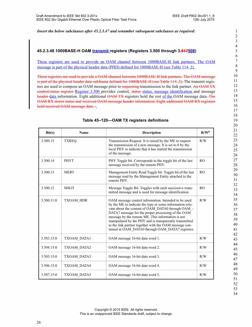
45.2.3.48 1000BASE-H OAM transmit registers (Registers 3.500 through 3.517508)
These registers are used to provide an OAM channel between 1000BASE-H link partners. The OAM message is part of the physical header data (PHD) defined for 1000BASE-H (see Table 114–2).
These registers are used to provide a OAM channel between 1000BASE-H link partners. The OAM message is part of the physical header data subframe defined for 1000BASE-H (see Table 114–2). The transmit regis-ters are used to compose an OAM message prior to requesting transmission to the link partner. An OAM TX control/status register Register 3.500 provides control, status status, message identification and message header data information. Eight additional OAM TX registers hold the rest of the OAM message data. The OAM RX stores status and received OAM message header information. Eight additional OAM RX registers hold received OAM message data. .
Table 45–120—OAM TX registers definitions
Bit(s) Name Description R/Wa
3.500.15 TXREQ Transmission Request. It is raised by the ME to request the transmission of a new message. It is set to 0 by the local PHY to indicate that it has started the transmission of the message.
R/W
3.500.14 PHYT PHY Toggle bit. Corresponds to the toggle bit of the last message received by the remote PHY.
RO
3.500.13 MERT Management Entity Read Toggle bit. Toggle bit of the last message read by the Management Entity attached to the remote PHY.
RO
3.500.12 MSGT Message Toggle Bit. Toggles with each successive trans-mitted message and is used for message identification.
RO
3.500.11:0 TXOAM_HDR OAM message control information. Intended to be used by the ME to indicate the type or some information rele-vant about the content of OAM_DATA0 through OAM_-DATA7 message for the proper processing of the OAM message by the remote ME. This information is not manipulated by the PHY and is transparently transmitted to the link partner together with the OAM message con-tained in OAM_DATA0 through OAM_DATA7 registers.
R/W
3.503.15:0 TXOAM_DATA1 OAM message 16-bit data word 1. R/W
3.504.15:0 TXOAM_DATA2 OAM message 16-bit data word 2. R/W
3.505.15:0 TXOAM_DATA3 OAM message 16-bit data word 3. R/W
3.506.15:0 TXOAM_DATA4 OAM message 16-bit data word 4. R/W
3.507.15:0 TXOAM_DATA5 OAM message 16-bit data word 5. R/W

Draft Amendment to IEEE Std 802.3-201x IEEE Draft P802.3bv/D1.1_8IEEE 802.3bv Gigabit Ethernet Over Plastic Optical Fiber Task Force 12th July 2015
Copyright © 2015 IEEE. All rights reserved.This is an unapproved IEEE Standards draft, subject to change.
27
1 2 3 4 5 6 7 8 9
10 11 12 13 14 15 16 17 18 19 20 21 22 23 24 25 26 27 28 29 30 31 32 33 34 35 36 37 38 39 40 41 42 43 44 45 46 47 48 49 50 51 52 53 54
The assignment of bits in the 1000BASE-H OAM transmit registers is shown in Table 45–121.
Table 45–121—1000BASE-H OAM transmit register bit definitions
Bit(s) Name Description R/Wa
aR/W = Read/Write, RO = Read only, SC = Self-clearing
3.500.15 TXO_REQ Transmission request. It is set to one by the Management Entity to request the transmission of a new OAM Message. It shall be set to zero by the local PHY to indicate that the message has been accepted for transmission.
R/W, SC
3.500.14 TXO_PHYT Transmit Message Phy Toggle bit. It corresponds to the toggle bit of the last message received by the remote PHY.
RO
3.500.13 TXO_MERT Transmit Message Management Entity Read Toggle bit. It corresponds to the toggle bit of the last message read by the Management Entity attached to the remote PHY.
RO
3.500.12 TXO_MSGT Transmit Message Toggle bit. This bit toggles with each new transmitted message and is used for message identification.
RO
3.500.11:0 TXO_TYPE Transmit Message data type information. Together with TXO_DATA1 through TXO_DATA8, it contains the payload of the OAM message. This information is not manipulated by the PHY and it is transparently transmitted to the link partner.
R/W
3.501.15:0 TXO_DATA1 Transmit message 16-bit data word 1. R/W
3.502.15:0 TXO_DATA2 Transmit message 16-bit data word 2. R/W
3.503.15:0 TXO_DATA3 Transmit message 16-bit data word 3. R/W
3.504.15:0 TXO_DATA4 Transmit message 16-bit data word 4. R/W
3.505.15:0 TXO_DATA5 Transmit message 16-bit data word 5. R/W
3.506.15:0 TXO_DATA6 Transmit message 16-bit data word 6. R/W
3.507.15:0 TXO_DATA7 Transmit message 16-bit data word 7. R/W
3.508.15:0 TXO_DATA8 Transmit message 16-bit data word 8. R/W
3.507.15:0 TXOAM_DATA6 OAM message 16-bit data word 6. R/W
3.508.15:0 TXOAM_DATA7 OAM message 16-bit data word 7. R/W
aR/W = Read/Write, RO = Read only
Table 45–120—OAM TX registers definitions (continued)
Bit(s) Name Description R/Wa

Draft Amendment to IEEE Std 802.3-201x IEEE Draft P802.3bv/D1.1_8IEEE 802.3bv Gigabit Ethernet Over Plastic Optical Fiber Task Force 12th July 2015
Copyright © 2015 IEEE. All rights reserved.This is an unapproved IEEE Standards draft, subject to change.
28
1 2 3 4 5 6 7 8 9
10 11 12 13 14 15 16 17 18 19 20 21 22 23 24 25 26 27 28 29 30 31 32 33 34 35 36 37 38 39 40 41 42 43 44 45 46 47 48 49 50 51 52 53 54
45.2.3.48.1 TXREQ TXO_REQ (3.500.15)
This bit is set to request the transmission of a new OAM message. It is reset to 0 by the local PHY to indicate that the transmission of the last requested message has started and it is ready to accept a new request for transmission.
This bit is set to one by the Management Entity to request the transmission of the OAM message written to registers 3.500 through 3.508. It shall be set to zero by the local PHY to indicate that the message has been accepted for transmission, and that the registers are free to accept a new message.
45.2.3.48.2 MSGT TXO_PHYT (3.500.14)
This bit is used for OAM message identification. It is toggled by the local PHY whenever a new message is accepted for transmission.
45.2.3.48.3 PHYT (3.500.13)
This The local PHY shall indicate in this bit is the MSGT TXO_MSGT bit of the last message received from by the remote PHY.
45.2.3.48.4 MERT TXO_MERT (3.500.1213)
This The local PHY shall indicate in this bit corresponds to the MSGT TXO_MSGT bit of the last message read by the ME Management Entity attached to the remote PHY. .
45.2.3.48.5 TXOAM_HDR TXO_MSGT (3.500.11:012)
These bits become the PHD.OAM.HDR bits upon transmission request.
This bit is used for message identification; it shall contain the toggle bit of the last message accepted by the local PHY for transmission. It shall be toggled by the local PHY when it accepts a new message for trans-mission (simultaneously with the falling of bit TXO_REQ)
Together with bits TXO_REQ, TXO_PHYT and TXO_MERT, this bit indicates the status of the OAM transmission channel. There can be up-to three outstanding messages in the transmission channel: message written in the OAM transmission registers that is waiting for transmission, the message being currently transmitted by the local PHY, and the message available in the OAM reception registers of the remote PHY which is waiting for processing of the remote Management Entity.
Table 45–122 shows all the possible values of the four control bits, and the corresponding status of the three possible outstanding OAM messages. The control bits can be either 0 or 1, the symbol ~ denotes logical not operator. Message K is the message currently being transmitted by the local PHY to the remote PHY, its associated toggle bit takes value ‘a’ as indicated by bit TXO_MSGT. Correspondingly, message K-1 denotes the previous message that was transmitted by the local PHY to the remote PHY. Its associated tog-gle bit takes value ‘~a’. Finally message K+1 corresponds to the OAM message being composed or yet to be requested for transmission by the local Management Entity. Its associated toggle bit will take value ‘~a’.
45.2.3.48.6 TXO_TYPE (3.500.11:0)
These bits contain the data type of the OAM message that will be transmitted by the local PHY. These bits are not manipulated in any way by the local or remote PHY and together with the TXO_DATAx bits carry the OAM message payload.

Table 45–122—List of all possible 1000BASE-H OAM message status
TXO_REQ
TXO_PHYT
TXO_MERT
TXO_MSGT
Message K+1 status Message K status Message K-1 status
0 a a a Not written by local ME
Sent by local PHYACK by remote PHYACK by remote ME
Sent by local PHYACK by remote PHYACK by remote ME
0 ~a ~a a Not written by local ME
Sent by local PHYNo ACK by remote PHYNo ACK by remote ME
Sent by local PHYACK by remote PHYACK by remote ME
0 a ~a s Not written by local ME
Sent by local PHYACK by remote PHYNo ACK by remote ME
Sent by local PHY ACK by remote PHYACK by remote ME
0 ~a a a Not written by local ME
Sent by local PHYNo ACK by remote PHYNo ACK by remote ME
Sent by local PHY ACK by remote PHYNo ACK by remote ME
1 a a a Written by local MEPending transmission by local PHY
Sent by local PHY ACK by remote PHYACK by remote ME
Sent by local PHY ACK by remote PHYACK by remote ME
1 ~a ~a a Written by local MEPending transmission by local PHY
Sent by local PHYNo ACK by remote PHYNo ACK by remote ME
Sent by local PHY ACK by remote PHYACK by remote ME
1 a ~a a Written by local MEPending transmission by local PHY
Sent by local PHYACK by remote PHYNo ACK by remote ME
Sent by local PHY ACK by remote PHYACK by remote ME
1 ~a a a Written by local MEPending transmission by local PHY
Sent by local PHYNo ACK by remote PHYNo ACK by remote ME
Sent by local PHYACK by remote PHYNo ACK by remote ME
Draft Amendment to IEEE Std 802.3-201x IEEE Draft P802.3bv/D1.1_8IEEE 802.3bv Gigabit Ethernet Over Plastic Optical Fiber Task Force 12th July 2015
Copyright © 2015 IEEE. All rights reserved.This is an unapproved IEEE Standards draft, subject to change.
29
1 2 3 4 5 6 7 8 9
10 11 12 13 14 15 16 17 18 19 20 21 22 23 24 25 26 27 28 29 30 31 32 33 34 35 36 37 38 39 40 41 42 43 44 45 46 47 48 49 50 51 52 53 54
45.2.3.48.7 TXOAM_DATA TXO_DATAx (Registers 3.501 through 3.508)
These registers contain the 128-bit OAM message data which become PHD.OAM.DATA upon transmission request. The first 16 transmitted bits (PHD.OAM.DATA0) and are stored in TXOAM_DATA1 (register 3.501) with subsequent bits stored sequentially in registers 3.502 through 3.508.
Table 45–123—1000BASE-X OAM RX registers definitions
Bit(s) Name Description R/Wa
3.500.15 RXVAL Reception Valid. The PHY sets to one to indicate that a new message has arrived and is ready for pro-cessing.
RO
3.510.14:13 Reserved Ignore on read RO

Draft Amendment to IEEE Std 802.3-201x IEEE Draft P802.3bv/D1.1_8IEEE 802.3bv Gigabit Ethernet Over Plastic Optical Fiber Task Force 12th July 2015
Copyright © 2015 IEEE. All rights reserved.This is an unapproved IEEE Standards draft, subject to change.
30
1 2 3 4 5 6 7 8 9
10 11 12 13 14 15 16 17 18 19 20 21 22 23 24 25 26 27 28 29 30 31 32 33 34 35 36 37 38 39 40 41 42 43 44 45 46 47 48 49 50 51 52 53 54
These registers contain the 128 data bits of the OAM message that will be transmitted by the local PHY
45.2.3.49 1000BASE-H OAM control/status receive registers (Registers 3.509 through 3.517)
These register are used to control and monitor the transmission of an OAM message stored in OAM_DATA 0:7. It includes 4 bits related to OAM message transmission and 12 user control bits for use as a header to the OAM message.
These registers are used to provide an OAM channel between 1000BASE-H link partners. The OAM message is part of the physical header data defined for 1000BASE-H (see Table 114–2).
The receive registers hold the OAM messages received from the link partner. Register 3.509 provides status information, message identification and message data information. Eight additional registers hold the rest of the received OAM message data
The assignment of bits in the 1000BASE-H OAM receive registers is shown in Table 45–124.
3.510.12 RX_MSGT Message Toggle Bit. Toggles with each successive trans-mitted message and is used for message identification.
RO
3.510.11:0 RX_OAM_HDR OAM message control information. Intended to be used by the ME to indicate the type or some information rele-vant about the content of OAM_DATA0 through OAM_-DATA7 message for the proper processing of the OAM message by the remote ME. This information is not manipulated by the PHY and is transparently transmitted to the link partner together with the OAM message con-tained in OAM_DATA0 through OAM_DATA7 registers.
RO
3.511.15:0 RX_OAM_DATA1 OAM message 16-bit data word 1. RO
3.512.15:0 RX_OAM_DATA2 OAM message 16-bit data word 2. RO
3.513.15:0 RX_OAM_DATA3 OAM message 16-bit data word 3. RO
3.514.15:0 RX_OAM_DATA4 OAM message 16-bit data word 4. RO
3.515.15:0 RX_OAM_DATA5 OAM message 16-bit data word 5. RO
3.516.15:0 RX_OAM_DATA6 OAM message 16-bit data word 6. RO
3.517.15:0 RX_OAM_DATA7 OAM message 16-bit data word 7. ROaR/W = RO = Read only
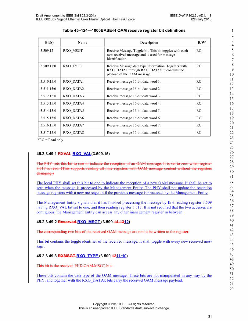
Table 45–124—1000BASE-H OAM receive register bit definitions
Bit(s) Name Description R/Wa
3.509.15 RXO_VAL Reception valid. The PHY sets this bit to one to indicate that a new message has arrived and it is ready for processing.
RO
3.509.14:13 Reserved Ignore on read RO
Table 45–123—1000BASE-X OAM RX registers definitions (continued)
Bit(s) Name Description R/Wa
Draft Amendment to IEEE Std 802.3-201x IEEE Draft P802.3bv/D1.1_8IEEE 802.3bv Gigabit Ethernet Over Plastic Optical Fiber Task Force 12th July 2015
Copyright © 2015 IEEE. All rights reserved.This is an unapproved IEEE Standards draft, subject to change.
31
1 2 3 4 5 6 7 8 9
10 11 12 13 14 15 16 17 18 19 20 21 22 23 24 25 26 27 28 29 30 31 32 33 34 35 36 37 38 39 40 41 42 43 44 45 46 47 48 49 50 51 52 53 54
45.2.3.49.1 RXVAL RXO_VAL(3.509.15)
The PHY sets this bit to one to indicate the reception of an OAM message. It is set to zero when register 3.517 is read. (This supports reading all nine registers with OAM message content without the registers changing.)
The local PHY shall set this bit to one to indicate the reception of a new OAM message. It shall be set to zero when the message is processed by the Management Entity. The PHY shall not update the reception message registers with a new message until the previous message is processed by the Management Entity.
The Management Entity signals that it has finished processing the message by first reading register 3.509 having RXO_VAL bit set to one, and then reading register 3.517. It is not required that the two accesses are contiguous; the Management Entity can access any other management register in between.
45.2.3.49.2 Reserved RXO_MSGT (3.509.14:1312)
The corresponding two bits of the received OAM message are not to be written to the register.
This bit contains the toggle identifier of the received message. It shall toggle with every new received mes-sage.
45.2.3.49.3 RXMSGT RXO_TYPE (3.509.1211:10)
This bit is the received PHD.OAM.MSGT bit.
These bits contain the data type of the OAM message. These bits are not manipulated in any way by the PHY, and together with the RXO_DATAx bits carry the received OAM message payload.
3.509.12 RXO_MSGT Receive Message Toggle bit. This bit toggles with each new received message and is used for message identification.
RO
3.509.11:0 RXO_TYPE Receive Message data type information. Together with RXO_DATA1 through RXO_DATA8, it contains the payload of the OAM message.
RO
3.510.15:0 RXO_DATA1 Receive message 16-bit data word 1. RO
3.511.15:0 RXO_DATA2 Receive message 16-bit data word 2. RO
3.512.15:0 RXO_DATA3 Receive message 16-bit data word 3. RO
3.513.15:0 RXO_DATA4 Receive message 16-bit data word 4. RO
3.514.15:0 RXO_DATA5 Receive message 16-bit data word 5. RO
3.515.15:0 RXO_DATA6 Receive message 16-bit data word 6. RO
3.516.15:0 RXO_DATA7 Receive message 16-bit data word 7. RO
3.517.15:0 RXO_DATA8 Receive message 16-bit data word 8. ROaRO = Read only
Table 45–124—1000BASE-H OAM receive register bit definitions
Bit(s) Name Description R/Wa
Draft Amendment to IEEE Std 802.3-201x IEEE Draft P802.3bv/D1.1_8IEEE 802.3bv Gigabit Ethernet Over Plastic Optical Fiber Task Force 12th July 2015
Copyright © 2015 IEEE. All rights reserved.This is an unapproved IEEE Standards draft, subject to change.
32
1 2 3 4 5 6 7 8 9
10 11 12 13 14 15 16 17 18 19 20 21 22 23 24 25 26 27 28 29 30 31 32 33 34 35 36 37 38 39 40 41 42 43 44 45 46 47 48 49 50 51 52 53 54
45.2.3.49.4 RXOAM_HDR RXO_DATAx (3.509.11:012)
These registers contain the 128 data bits are of the received PHD.OAM.HDR bitsOAM message.
45.2.3.49.5 RXOAM_DATA (Registers 3.510 through 3.517)
These registers contain the received 128-bit PHD.OAM.DATA. The first 16 received bits are PHD.OAM.DATA0 and are stored in RXOAM_DATA1 (register 3.510) with subsequent bits stored sequentially in registers 3.511 through 3.517.
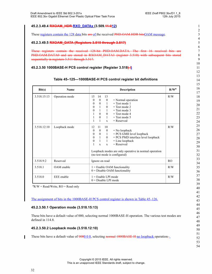
45.2.3.50 1000BASE-H PCS control register (Register 3.518)
Table 45–125—1000BASE-H PCS control register bit definitions
Bit(s) Name Description R/Wa
aR/W = Read/Write, RO = Read only
3.518.15:13 Operation mode 15 14 13 0 0 0 = Normal operation 0 0 1 = Test mode 1 0 1 0 = Test mode 2 0 1 1 = Test mode 3 1 0 0 = Test mode 4 1 0 1 = Test mode 5 1 1 x = Reserved
R/W
3.518.12:10 Loopback mode 12 11 10 0 0 0 = No loopback 0 0 1 = PCS GMII level loopback 0 1 0 = PCS PMD interface level loopback 0 1 1 = Line loopback 1 x x = Reserved
Loopback modes are only operative in normal operation (no test mode is configured)
R/W
3.518.9:2 Reserved Ignore on read RO
3.518.1 OAM enable 1 = Enable OAM functionality0 = Disable OAM functionality
R/W
3.518.0 EEE enable 1 = Enable LPI mode0 = Disable LPI mode
R/W
!)
The assignment of bits in the 1000BASE-H PCS control register is shown in Table 45–126.
45.2.3.50.1 Operation mode (3.518.15:13)
These bits have a default value of 000, selecting normal 1000BASE-H operation. The various test modes are defined in 114.8.
45.2.3.50.2 Loopback mode (3.518.12:10)
These bits have a default value of 0000 0 0, selecting normal 1000BASE-H no loopback operation. .
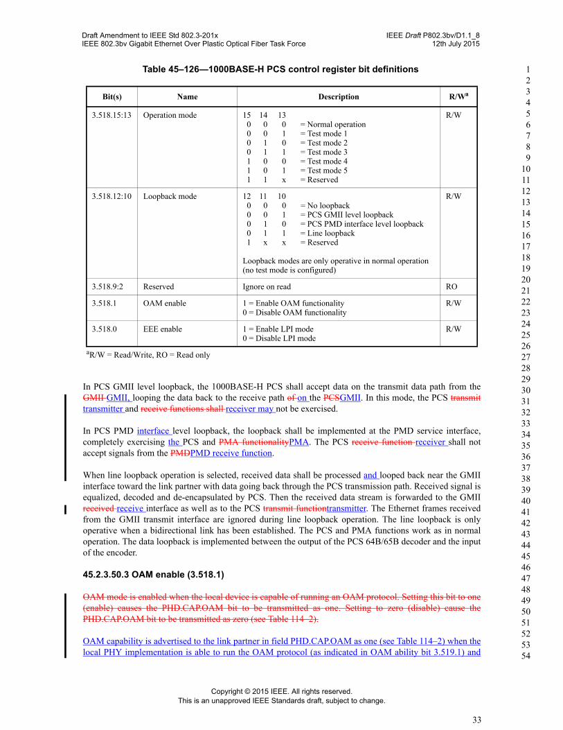
Table 45–126—1000BASE-H PCS control register bit definitions
Bit(s) Name Description R/Wa
3.518.15:13 Operation mode 15 14 13 0 0 0 = Normal operation 0 0 1 = Test mode 1 0 1 0 = Test mode 2 0 1 1 = Test mode 3 1 0 0 = Test mode 4 1 0 1 = Test mode 5 1 1 x = Reserved
R/W
3.518.12:10 Loopback mode 12 11 10 0 0 0 = No loopback 0 0 1 = PCS GMII level loopback 0 1 0 = PCS PMD interface level loopback 0 1 1 = Line loopback 1 x x = Reserved
Loopback modes are only operative in normal operation (no test mode is configured)
R/W
3.518.9:2 Reserved Ignore on read RO
3.518.1 OAM enable 1 = Enable OAM functionality0 = Disable OAM functionality
R/W
3.518.0 EEE enable 1 = Enable LPI mode0 = Disable LPI mode
R/W
Draft Amendment to IEEE Std 802.3-201x IEEE Draft P802.3bv/D1.1_8IEEE 802.3bv Gigabit Ethernet Over Plastic Optical Fiber Task Force 12th July 2015
Copyright © 2015 IEEE. All rights reserved.This is an unapproved IEEE Standards draft, subject to change.
33
1 2 3 4 5 6 7 8 9
10 11 12 13 14 15 16 17 18 19 20 21 22 23 24 25 26 27 28 29 30 31 32 33 34 35 36 37 38 39 40 41 42 43 44 45 46 47 48 49 50 51 52 53 54
In PCS GMII level loopback, the 1000BASE-H PCS shall accept data on the transmit data path from the GMII GMII, looping the data back to the receive path of on the PCSGMII. In this mode, the PCS transmit transmitter and receive functions shall receiver may not be exercised.
In PCS PMD interface level loopback, the loopback shall be implemented at the PMD service interface, completely exercising the PCS and PMA functionalityPMA. The PCS receive function receiver shall not accept signals from the PMDPMD receive function.
When line loopback operation is selected, received data shall be processed and looped back near the GMII interface toward the link partner with data going back through the PCS transmission path. Received signal is equalized, decoded and de-encapsulated by PCS. Then the received data stream is forwarded to the GMII received receive interface as well as to the PCS transmit functiontransmitter. The Ethernet frames received from the GMII transmit interface are ignored during line loopback operation. The line loopback is only operative when a bidirectional link has been established. The PCS and PMA functions work as in normal operation. The data loopback is implemented between the output of the PCS 64B/65B decoder and the input of the encoder.
45.2.3.50.3 OAM enable (3.518.1)
OAM mode is enabled when the local device is capable of running an OAM protocol. Setting this bit to one (enable) causes the PHD.CAP.OAM bit to be transmitted as one. Setting to zero (disable) cause the PHD.CAP.OAM bit to be transmitted as zero (see Table 114–2).
OAM capability is advertised to the link partner in field PHD.CAP.OAM as one (see Table 114–2) when the local PHY implementation is able to run the OAM protocol (as indicated in OAM ability bit 3.519.1) and
aR/W = Read/Write, RO = Read only
Draft Amendment to IEEE Std 802.3-201x IEEE Draft P802.3bv/D1.1_8IEEE 802.3bv Gigabit Ethernet Over Plastic Optical Fiber Task Force 12th July 2015
Copyright © 2015 IEEE. All rights reserved.This is an unapproved IEEE Standards draft, subject to change.
34
1 2 3 4 5 6 7 8 9
10 11 12 13 14 15 16 17 18 19 20 21 22 23 24 25 26 27 28 29 30 31 32 33 34 35 36 37 38 39 40 41 42 43 44 45 46 47 48 49 50 51 52 53 54
this bit is set. Otherwise, PHD.CAP.OAM field is transmitted as zero. The value of this bit is reflected in field PHD.CAP.OAM only after a PMA reset.
45.2.3.50.4 EEE enable (3.518.0)
EEE capability of the local PHY is controlled with this bit. Setting this bit to one (enable) causes the PHD.CAP.LPI bit to be transmitted as one. Setting to zero (disable) cause the PHD.CAP.LPI bit to be transmitted as zero (see Table 114–2.
EEE capability is advertised to the link partner in field PHD.CAP.LPI as one (see Table 114–2) when the local PHY implements EEE (as indicated in EEE ability bit 3.519.0) and this bit is set. Otherwise, PHD.CAP.LPI field is transmitted as zero. The value of this bit is reflected in field PHD.CAP.LPI only after a PMA reset.
Draft Amendment to IEEE Std 802.3-201x IEEE Draft P802.3bv/D1.1_8IEEE 802.3bv Gigabit Ethernet Over Plastic Optical Fiber Task Force 12th July 2015
Copyright © 2015 IEEE. All rights reserved.This is an unapproved IEEE Standards draft, subject to change.
35
1 2 3 4 5 6 7 8 9
10 11 12 13 14 15 16 17 18 19 20 21 22 23 24 25 26 27 28 29 30 31 32 33 34 35 36 37 38 39 40 41 42 43 44 45 46 47 48 49 50 51 52 53 54
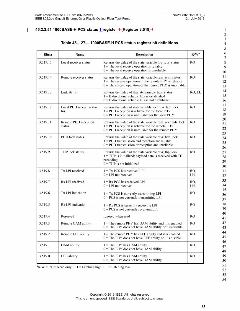
45.2.3.51 1000BASE-H PCS status 1 register 1 (Register 3.519) !
Table 45–127— 1000BASE-H PCS status register bit definitions
Bit(s) Name Description R/Wa
aR/W = RO = Read only, LH = Latching high, LL = Latching low
3.519.15 Local receiver status Returns the value of the state variable loc_rcvr_status1 = The local receive operation is reliable0 = The local receive operation is unreliable
RO
3.519.14 Remote receiver status Returns the value of the state variable rem_rcvr_status1 = The receive operation of the remote PHY is reliable0 = The receive operation of the remote PHY is unreliable
RO
3.519.13 Link status Returns the value of thestate variable link_status1 = Bidirectional reliable link is established0 = Bidirectional reliable link is not established
RO, LL
3.519.12 Local PHD reception sta-tus
Returns the value of state variable loc_rcvr_hdr_lock1 = PHD reception is reliable for the local PHY0 = PHD reception is unreliable for the local PHY
RO
3.519.11 Remote PHD reception status
Returns the value of the state variable rem_rcvr_hdr_lock1 = PHD reception is reliable for the remote PHY0 = PHD reception is unreliable for the remote PHY
RO
3.519.10 PHD lock status Returns the value of the state variable rcvr_hdr_lock1 = PHD transmission and reception are reliable0 = PHD transmission or reception are unreliable
RO
3.519.9 THP lock status Returns the value of the state variable rcvr_thp_lock1 = THP is initialized; payload data is received with TH precoding0 = THP is not initialized
RO
3.519.8 Tx LPI received 1 = Tx PCS has received LPI0 = LPI not received
RO, LH
3.519.7 Rx LPI received 1 = Rx PCS has received LPI0 = LPI not received
RO, LH
3.519.6 Tx LPI indication 1 = Tx PCS is currently transmitting LPI0 = PCS is not currently transmitting LPI
RO
3.519.5 Rx LPI indication 1 = Rx PCS is currently receiving LPI0 = PCS is not currently receiving LPI
RO
3.519.4 Reserved Ignored when read RO
3.519.3 Remote OAM ability 1 = The remote PHY has OAM ability and it is enabled0 = The PHY does not have OAM ability or it is disable
RO
3.519.2 Remote EEE ability 1 = The remote PHY has EEE ability and it is enabled0 = The PHY does not have EEE ability or it is disable
RO
3.519.1 OAM ability 1 = The PHY has OAM ability0 = The PHY does not have OAM ability
RO
3.519.0 EEE ability 1 = The PHY has OAM ability0 = The PHY does not have OAM ability
RO
Draft Amendment to IEEE Std 802.3-201x IEEE Draft P802.3bv/D1.1_8IEEE 802.3bv Gigabit Ethernet Over Plastic Optical Fiber Task Force 12th July 2015
Copyright © 2015 IEEE. All rights reserved.This is an unapproved IEEE Standards draft, subject to change.
36
1 2 3 4 5 6 7 8 9
10 11 12 13 14 15 16 17 18 19 20 21 22 23 24 25 26 27 28 29 30 31 32 33 34 35 36 37 38 39 40 41 42 43 44 45 46 47 48 49 50 51 52 53 54
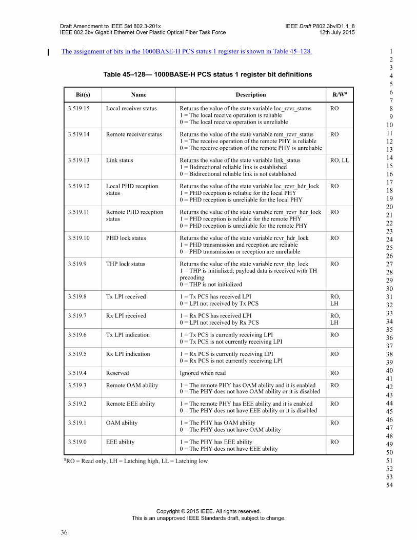
The assignment of bits in the 1000BASE-H PCS status 1 register is shown in Table 45–128.
Table 45–128— 1000BASE-H PCS status 1 register bit definitions
Bit(s) Name Description R/Wa
aRO = Read only, LH = Latching high, LL = Latching low
3.519.15 Local receiver status Returns the value of the state variable loc_rcvr_status1 = The local receive operation is reliable0 = The local receive operation is unreliable
RO
3.519.14 Remote receiver status Returns the value of the state variable rem_rcvr_status1 = The receive operation of the remote PHY is reliable0 = The receive operation of the remote PHY is unreliable
RO
3.519.13 Link status Returns the value of the state variable link_status1 = Bidirectional reliable link is established0 = Bidirectional reliable link is not established
RO, LL
3.519.12 Local PHD reception status
Returns the value of the state variable loc_rcvr_hdr_lock1 = PHD reception is reliable for the local PHY0 = PHD reception is unreliable for the local PHY
RO
3.519.11 Remote PHD reception status
Returns the value of the state variable rem_rcvr_hdr_lock1 = PHD reception is reliable for the remote PHY0 = PHD reception is unreliable for the remote PHY
RO
3.519.10 PHD lock status Returns the value of the state variable rcvr_hdr_lock1 = PHD transmission and reception are reliable0 = PHD transmission or reception are unreliable
RO
3.519.9 THP lock status Returns the value of the state variable rcvr_thp_lock1 = THP is initialized; payload data is received with TH precoding0 = THP is not initialized
RO
3.519.8 Tx LPI received 1 = Tx PCS has received LPI0 = LPI not received by Tx PCS
RO, LH
3.519.7 Rx LPI received 1 = Rx PCS has received LPI0 = LPI not received by Rx PCS
RO, LH
3.519.6 Tx LPI indication 1 = Tx PCS is currently receiving LPI0 = Tx PCS is not currently receiving LPI
RO
3.519.5 Rx LPI indication 1 = Rx PCS is currently receiving LPI0 = Rx PCS is not currently receiving LPI
RO
3.519.4 Reserved Ignored when read RO
3.519.3 Remote OAM ability 1 = The remote PHY has OAM ability and it is enabled0 = The PHY does not have OAM ability or it is disabled
RO
3.519.2 Remote EEE ability 1 = The remote PHY has EEE ability and it is enabled0 = The PHY does not have EEE ability or it is disabled
RO
3.519.1 OAM ability 1 = The PHY has OAM ability0 = The PHY does not have OAM ability
RO
3.519.0 EEE ability 1 = The PHY has EEE ability0 = The PHY does not have EEE ability
RO
Draft Amendment to IEEE Std 802.3-201x IEEE Draft P802.3bv/D1.1_8IEEE 802.3bv Gigabit Ethernet Over Plastic Optical Fiber Task Force 12th July 2015
Copyright © 2015 IEEE. All rights reserved.This is an unapproved IEEE Standards draft, subject to change.
37
1 2 3 4 5 6 7 8 9
10 11 12 13 14 15 16 17 18 19 20 21 22 23 24 25 26 27 28 29 30 31 32 33 34 35 36 37 38 39 40 41 42 43 44 45 46 47 48 49 50 51 52 53 54
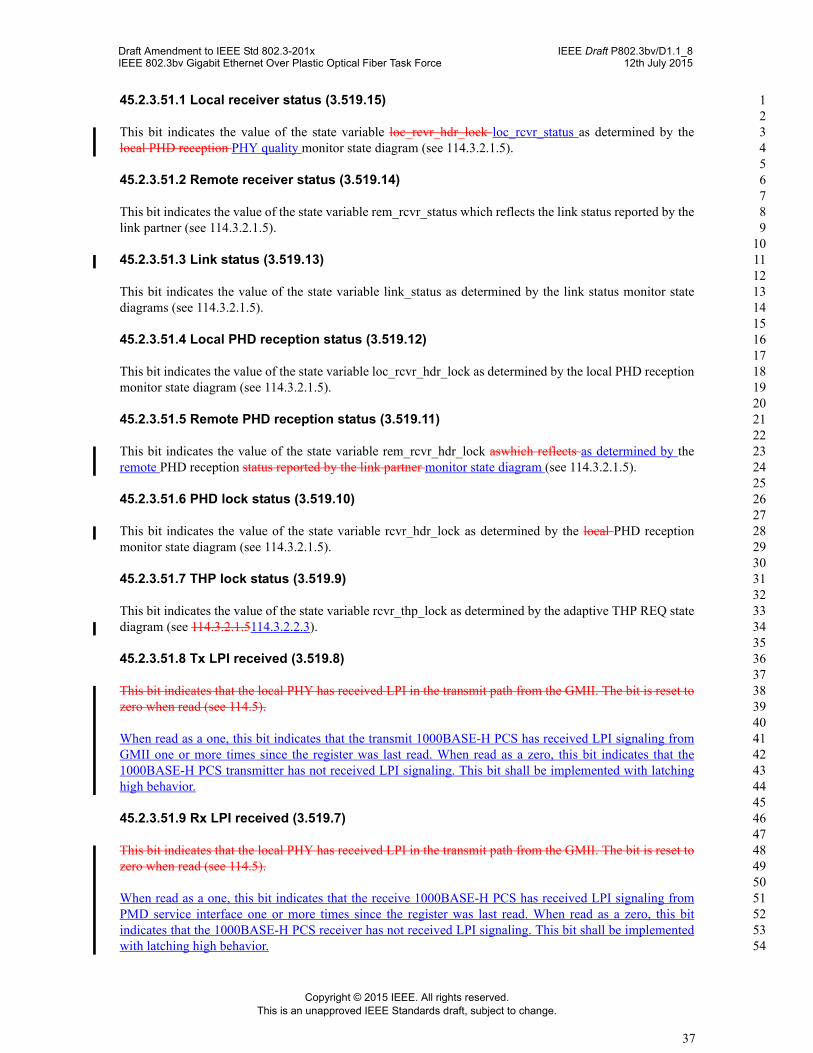
45.2.3.51.1 Local receiver status (3.519.15)
This bit indicates the value of the state variable loc_rcvr_hdr_lock loc_rcvr_status as determined by the local PHD reception PHY quality monitor state diagram (see 114.3.2.1.5).
45.2.3.51.2 Remote receiver status (3.519.14)
This bit indicates the value of the state variable rem_rcvr_status which reflects the link status reported by the link partner (see 114.3.2.1.5).
45.2.3.51.3 Link status (3.519.13)
This bit indicates the value of the state variable link_status as determined by the link status monitor state diagrams (see 114.3.2.1.5).
45.2.3.51.4 Local PHD reception status (3.519.12)
This bit indicates the value of the state variable loc_rcvr_hdr_lock as determined by the local PHD reception monitor state diagram (see 114.3.2.1.5).
45.2.3.51.5 Remote PHD reception status (3.519.11)
This bit indicates the value of the state variable rem_rcvr_hdr_lock aswhich reflects as determined by the remote PHD reception status reported by the link partner monitor state diagram (see 114.3.2.1.5).
45.2.3.51.6 PHD lock status (3.519.10)
This bit indicates the value of the state variable rcvr_hdr_lock as determined by the local PHD reception monitor state diagram (see 114.3.2.1.5).
45.2.3.51.7 THP lock status (3.519.9)
This bit indicates the value of the state variable rcvr_thp_lock as determined by the adaptive THP REQ state diagram (see 114.3.2.1.5114.3.2.2.3).
45.2.3.51.8 Tx LPI received (3.519.8)
This bit indicates that the local PHY has received LPI in the transmit path from the GMII. The bit is reset to zero when read (see 114.5).
When read as a one, this bit indicates that the transmit 1000BASE-H PCS has received LPI signaling from GMII one or more times since the register was last read. When read as a zero, this bit indicates that the 1000BASE-H PCS transmitter has not received LPI signaling. This bit shall be implemented with latching high behavior.
45.2.3.51.9 Rx LPI received (3.519.7)
This bit indicates that the local PHY has received LPI in the transmit path from the GMII. The bit is reset to zero when read (see 114.5).
When read as a one, this bit indicates that the receive 1000BASE-H PCS has received LPI signaling from PMD service interface one or more times since the register was last read. When read as a zero, this bit indicates that the 1000BASE-H PCS receiver has not received LPI signaling. This bit shall be implemented with latching high behavior.
Draft Amendment to IEEE Std 802.3-201x IEEE Draft P802.3bv/D1.1_8IEEE 802.3bv Gigabit Ethernet Over Plastic Optical Fiber Task Force 12th July 2015
Copyright © 2015 IEEE. All rights reserved.This is an unapproved IEEE Standards draft, subject to change.
38
1 2 3 4 5 6 7 8 9
10 11 12 13 14 15 16 17 18 19 20 21 22 23 24 25 26 27 28 29 30 31 32 33 34 35 36 37 38 39 40 41 42 43 44 45 46 47 48 49 50 51 52 53 54
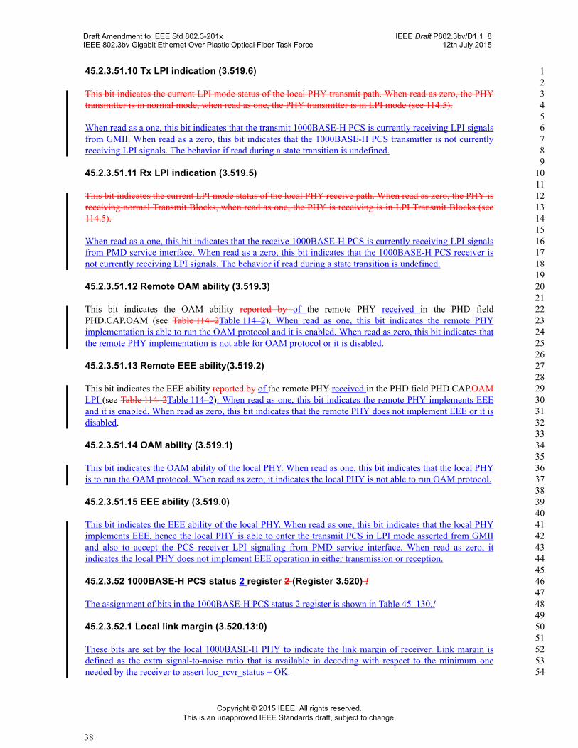
45.2.3.51.10 Tx LPI indication (3.519.6)
This bit indicates the current LPI mode status of the local PHY transmit path. When read as zero, the PHY transmitter is in normal mode, when read as one, the PHY transmitter is in LPI mode (see 114.5).
When read as a one, this bit indicates that the transmit 1000BASE-H PCS is currently receiving LPI signals from GMII. When read as a zero, this bit indicates that the 1000BASE-H PCS transmitter is not currently receiving LPI signals. The behavior if read during a state transition is undefined.
45.2.3.51.11 Rx LPI indication (3.519.5)
This bit indicates the current LPI mode status of the local PHY receive path. When read as zero, the PHY is receiving normal Transmit Blocks, when read as one, the PHY is receiving is in LPI Transmit Blocks (see 114.5).
When read as a one, this bit indicates that the receive 1000BASE-H PCS is currently receiving LPI signals from PMD service interface. When read as a zero, this bit indicates that the 1000BASE-H PCS receiver is not currently receiving LPI signals. The behavior if read during a state transition is undefined.
45.2.3.51.12 Remote OAM ability (3.519.3)
This bit indicates the OAM ability reported by of the remote PHY received in the PHD field PHD.CAP.OAM (see Table 114–2Table 114–2). When read as one, this bit indicates the remote PHY implementation is able to run the OAM protocol and it is enabled. When read as zero, this bit indicates that the remote PHY implementation is not able for OAM protocol or it is disabled.
45.2.3.51.13 Remote EEE ability(3.519.2)
This bit indicates the EEE ability reported by of the remote PHY received in the PHD field PHD.CAP.OAM LPI (see Table 114–2Table 114–2). When read as one, this bit indicates the remote PHY implements EEE and it is enabled. When read as zero, this bit indicates that the remote PHY does not implement EEE or it is disabled.
45.2.3.51.14 OAM ability (3.519.1)
This bit indicates the OAM ability of the local PHY. When read as one, this bit indicates that the local PHY is to run the OAM protocol. When read as zero, it indicates the local PHY is not able to run OAM protocol.
45.2.3.51.15 EEE ability (3.519.0)
This bit indicates the EEE ability of the local PHY. When read as one, this bit indicates that the local PHY implements EEE, hence the local PHY is able to enter the transmit PCS in LPI mode asserted from GMII and also to accept the PCS receiver LPI signaling from PMD service interface. When read as zero, it indicates the local PHY does not implement EEE operation in either transmission or reception.
45.2.3.52 1000BASE-H PCS status 2 register 2 (Register 3.520) !
The assignment of bits in the 1000BASE-H PCS status 2 register is shown in Table 45–130.!
45.2.3.52.1 Local link margin (3.520.13:0)
These bits are set by the local 1000BASE-H PHY to indicate the link margin of receiver. Link margin is defined as the extra signal-to-noise ratio that is available in decoding with respect to the minimum one needed by the receiver to assert loc_rcvr_status = OK.

Draft Amendment to IEEE Std 802.3-201x IEEE Draft P802.3bv/D1.1_8IEEE 802.3bv Gigabit Ethernet Over Plastic Optical Fiber Task Force 12th July 2015
Copyright © 2015 IEEE. All rights reserved.This is an unapproved IEEE Standards draft, subject to change.
39
1 2 3 4 5 6 7 8 9
10 11 12 13 14 15 16 17 18 19 20 21 22 23 24 25 26 27 28 29 30 31 32 33 34 35 36 37 38 39 40 41 42 43 44 45 46 47 48 49 50 51 52 53 54
This local link Link margin is measured as extra SNR available in decoding with respect to min SNR needed to provide loc_rcvr_status = OK. It is fixedprovided fix-point formatted (14,6) and is provided in log2 (.) units e.gunits. LM = For example, a link margin of 3.5 dB is equivalent to log2(100.35) = ) = 1.1627 in log2units, which is equal equivalent to hexadecimal 0x012A in (14,6) fixed-point format. The formal description for converting fixed point numbers to floating point and viceversa is in 114.3.3.
45.2.3.53 1000BASE-H PCS status 3 register 3 (Register 3.521) !
The assignment of bits in the 1000BASE-H PCS status 3 register is shown in Table 45–132.!
Table 45–129— 1000BASE-H PCS status register 2 bit definitions
Bit(s) Name Description R/Wa
3.520.15:14 Reserved Ignore when read RO
3.520.13:0 Local link margin Reports the local link margin ROaR/W = RO = Read only
Table 45–130— 1000BASE-H PCS status 2 register bit definitions
Bit(s) Name Description R/Wa
3.520.15:14 Reserved Ignore when read RO
3.520.13:0 Local link margin Reports the local link margin ROaRO = Read only
Table 45–131— 1000BASE-H PCS status register 3 bit definitions
Bit(s) Name Description R/Wa
aRO = Read only
3.521.15:14 Reserved Ignore when read RO
3.521.13:0 Remote link margin The detected link margin reported by the link partner RO
Table 45–132— 1000BASE-H PCS status 3 register bit definitions
Bit(s) Name Description R/Wa
aRO = Read only
3.521.15:14 Reserved Ignore when read RO
3.521.13:0 Remote link margin The detected link margin reported by the link partner RO

Draft Amendment to IEEE Std 802.3-201x IEEE Draft P802.3bv/D1.1_8IEEE 802.3bv Gigabit Ethernet Over Plastic Optical Fiber Task Force 12th July 2015
Copyright © 2015 IEEE. All rights reserved.This is an unapproved IEEE Standards draft, subject to change.
40
1 2 3 4 5 6 7 8 9
10 11 12 13 14 15 16 17 18 19 20 21 22 23 24 25 26 27 28 29 30 31 32 33 34 35 36 37 38 39 40 41 42 43 44 45 46 47 48 49 50 51 52 53 54
45.2.3.53.1 Remote link margin (3.521.13:0)
This field reports the remote link margin measured as extra SNR available in decoding with respect to min SNR needed to provide rem_rcvr_status = OK.
These bits reports the link margin of the remote PHY receiver as it is received in the PHD field PHD.RX.LINKMARGIN (see Table 114–2). Remote link margin is the extra signal-to-noise ratio available in the remote receiver with respect to the minimum one needed to assert rem_rcvr_status = OK. This register has the same fixed-point format than register 3.520.13:0 (see 45.2.3.52.1).
45.2.3.54 1000BASE-H PCS status 4 register 4 (Register 3.522) !
The assignment of bits in the 1000BASE-H PCS status 4 register is shown in Table 45–134. !
45.2.3.54.1 BER test mode counter reset (3.522.15)
This bit is set to one to reset the BER test mode counter to zero. The bit is self clearing, returning to zero when reset is complete.
45.2.3.54.2 BER test mode counter (3.522.14:0)
This These bits are a 15-bit counter that counts the number of bits received with value 1 at the output of the binary descrambler, when the PHY receiver is operating in test mode 1. The counter is These bits shall be reset to all zeroes when entering the PCS receiver enters test mode 1 as indicated by indication of the link partner (see 114.8.1) or when reset is performed instructed by writing a one to 3.522.15 BER test mode counter reset. These bits shall be held at all ones in the case of overflow.
Table 45–133— PCS status register 4 register bit definitions
Bit(s) Name Description R/Wa
aR/W = Read/Write, RO = Read only
3.522.15 BER test mode counter reset
1 = reset the BER test mode counter PcsTBD3.14:00 = ignored
R/W
3.521.14:0 BER test mode counter A 15-bit counter used when operating in test mode 1. RO
Table 45–134— 1000BASE-H PCS status 4 register bit definitions
Bit(s) Name Description R/Wa
aR/W = Read/Write, RO = Read only, SC = Self-clearing, NR = Non Roll-over
3.522.15 BER test mode counter reset
1 = reset the BER test mode counter 3.522.14:00 = ignored
R/W, SC
3.522.14:0 BER test mode counter A 15-bit counter used when operating in test mode 1. RO, NR