4500 series wattmeter manual - alpha rf systems · 10 • 1.2 4510 & 4520 front panel layout...
TRANSCRIPT
4500 Series Wattmeter Manual Alpha Radio Products www.alpharadioproducts
1
Alpha Radio Products
presents
4500 Series Wattmeter Manual
FCC Notice
This equipment has been tested and found to comply with the limits for a Class B digital device, pursuant to part 15 of the FCC Rules. These limits are designed to provide reasonable protection against harmful interference in a residential installation. This equipment generates, uses and can radiate radio frequency energy and, if not installed and used in accordance with the instructions, may cause harmful interference to radio communications. However, there is no guarantee that interference will not occur in a particular installation. If this equipment does cause harmful interference to radio or television reception, which can be determined by turn-ing the equipment off and on, the user is encouraged to try to correct the interference by one or more of the following measures:
·Reorient or relocate the receiving antenna. ·Increase the separation between the equipment and receiver. ·Connect the equipment into an outlet on a circuit different from that to which the receiver is connected. ·Consult the dealer or an experienced radio/TV technician for help.
Changes or modifications to this device not expressly approved by the Manufacturer could void the user’s authority to operate this equipment.
This document is copyright 2006 by Alpha Radio Products LLC. of Boulder, Colorado. Reproduction for resale or redistribution is strictly prohibited.All rights reserved.

Alpha Radio Products 4500 Series Wattmeter Manualwww.alpharadioproducts
2
4500 Series Wattmeter Manual Alpha Radio Products www.alpharadioproducts
3
Table of ContentsPage Section
7 • 1.1 General Overview10 • 1.2 4510 & 4520 Front Panel Layout and Functions10 • 1.3 All Wattmeters Rear Panel Layout and Functions11 • 1.4 Internal Controls and Functions11 • 1.5 Connecting the Wattmeter11 • 1.5.1 Adjusting the Analog Meter on the 4510 & 4520 11 • 1.5.2 Connecting the Power Supply (all models)12 • 1.5.3 Connecting the RF Coaxial Cables (all models)13 • 1.5.4 Connecting the 9-pin D Connector (all models)13 • 1.5.5 Powering On the 4510 & 452013 • 1.5.6 Powering On the 4505 & 451514 • 1.6 Operation of the 4510 & 452014 • 1.6.1 Selecting RF operating mode – PEP or Tune 15 • 1.6.2 Selecting the Analog Meter Display Function15 • 1.6.3 Interpreting the Analog Meter Scaling on the 451016 • 1.6.3.1 Interpreting the Analog Meter Scaling on the 452017 • 1.6.4 Measuring RF Output Power17 • 1.6.4.1 Displaying Measured RF Output Power on the Seven Segment LED Display18 • 1.6.4.2 Displaying Measured RF Output Power on the Analog Meter18 • 1.6.5 Displaying Measured Reflected Power on the Analog Meter18 • 1.6.6 Displaying Measured SWR on the Analog Meter18 • 1.6.7 Selecting the Correct Power Segment19 • 1.6.7.1 Using the AutoSense Mode20 • 1.6.7.2 Using the Manual Mode21 • 1.7 Windows Monitoring Application22 • 1.8 Communicating with the wattmeter via the RS-232 port22 • 1.9 Warranty23 • Appendix A Troubleshooting23 • Unit will not power on23 • High SWR always indicated23 • Erratic RS-232 Operation at high power 24 • Appendix B Wattmeter Specifications24 • Table B1. Wattmeter Specifications
Alpha Radio Products 4500 Series Wattmeter Manualwww.alpharadioproducts
4
25 • Table B2. Elpac FW1812-760 Power Supply Specification26 • Appendix C Changing the Back Panel RF Coaxial Connectors27 • Appendix D Serial Interface Specification30 • Appendix E Theory of Operation32 • Appendix F Sample Measurement Data of Wattmeter 32 • Typical Error vs. Frequency32 • Typical Error vs. Temperature33 • Typical Minimum Detectable SWR vs. Frequency33 • Typical Directivity vs. Frequency
Diagrams and Figures8 • Figure 1.2-1 Wattmeter Functionality Diagram9 • Figure 1.2-2 Wattmeter Functionality Diagram10 • Figure 1.3-1 Wattmeter Rear Diagram22 • Figure 1.7.1 SoftMeter Diagram31 • Figure E1. Functional block Diagram of the Model 4500 HF Wattmeter
Tables14 • Table 1.6.1-1 Mode / Algorithm / Application16 • Table 1.6.3-1. 4510 Analog Meter Scale 0-1016 • Table 1.6.3-2. 4510 Analog Meter Scale 0-316 • Table 1.6.3-3. 4520 Analog Meter Scale 0-5017 • Table 1.6.3-4. 4520 Analog Meter Scale 0-10017 • Table 1.6.3-5. 4510 Analog Meter Scale 0-20019 • Table 1.6.7-1. Summary of 4510 Analog Meter Scale relative to Power Segment Switch19 • Table 1.6.7-2. Summary of 4520 Analog Meter Scale relative to Power Segment Switch
4500 Series Wattmeter Manual Alpha Radio Products www.alpharadioproducts
5
Owner InformationModel Number:
Serial Number:_________________________
Purchaser:_________________________
Date Purchased:_________________________
Place Purchased:_________________________

Alpha Radio Products 4500 Series Wattmeter Manualwww.alpharadioproducts
6
4500 Series Wattmeter Manual Alpha Radio Products www.alpharadioproducts
7
1.1 General Overview
Congratulations! You have purchased an Alpha Radio Products Alpha/Power™ High Frequency RF Power Meter, a laboratory grade device capable of measuring and display-ing Transmit Forward power, Reflected power, Delivered power, and SWR at continuously variable power levels. The 4505 and 4510 wattmeters cover a range from 200 milliwatts (-7 dBW) to 3 kilowatts (+34.8 dBW), and the 4515 and 4520 wattmeters cover a range from 1 watt (0 dBW) to 5 kilowatts (+37 dBW). The wattmeter is a self-contained unit and does not require the operator to purchase or change any slugs or other accessories to operate over the entire power range.
The wattmeter is highly automated and includes circuitry to protect the unit against typical operating anomalies. The wattmeter automatically determines the direction of power flow, allowing the rear panel coax connectors to be connected interchangeably between RF source (transmitter) and load (antenna). The coax connectors normally supplied are UHF style (e.g., they mate with PL-259 plugs) but they are field replaceable if a different style of connector is preferred (BNC or type N) or if the connectors become damaged.
The wattmeter is capable of simultaneously displaying the Transmitter output power level in the seven segment LED display, plus either Reflected power, SWR, or Forward power in the analog meter display. Transmitter output power can be displayed as either Forward power or Delivered power (Forward Power minus Reflected Power). The four models of wattmeter report all measurements as streaming data through the RS-232 port located on the back of the unit, thus enabling real time data logging of station performance. Note: that the 4505 and 4515 are designed without built-in displays and only display data via the SoftMeter software package.
The wattmeter is designed to work across the frequency segment 1.8 MHz to 30 MHz. The RF output levels reported by the wattmeter are temperature and frequency com-pensated to improve accuracy. Transmitter output power (either as Forward power or as Delivered power) is continuously displayed using the seven segment LED readout, and Forward, Reflected, and SWR are individually selected and displayed using the analog meter.
The wattmeter is designed to switch automatically between nine different Power Seg-ments, permitting optimum analog meter deflection and display accuracy. Alternatively, at the touch of a switch, any one of nine specific Power Segments can be individually selected from the front panel and the analog meter display “locked” into that Power Seg-ment. Returning the meter to the automatic mode simply requires pressing one switch. As a built in safeguard, if the applied power exceeds the full-scale reading when the unit
Alpha Radio Products 4500 Series Wattmeter Manualwww.alpharadioproducts
8
is set to one selected power output level, no damage will occur to the analog meter.
The wattmeter is supplied with a universal-input (100-240 V AC, 50-60 Hz) power supply that provides the unit a 12-Volt DC source. It is internally protected against reverse polar-ity and DC input transients that do not exceed 16 Volts. Upon removal of the DC power source, the analog meter movement is automatically shorted. The unit also features in-creased meter damping that allows rapid meter response during normal operation. These features also reduce the likelihood of meter damage during transit.
P
0.3 1 3 10 30 100 300 1000 3000
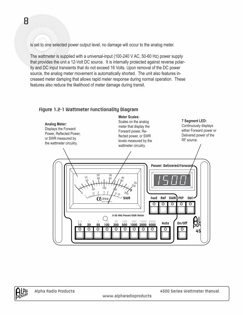
Analog Meter:Displays the Forward Power, Reflected Power, or SWR measured by the wattmeter circuitry.
Meter Scales:Scales on the analog meter that display the Forward power, Re-flected power, or SWR levels measured by the wattmeter circuitry.
7 Segment LED:Continuously displays either Forward power or Delivered power of the RF source.
Figure 1.2-1 Wattmeter Functionality Diagram
4500 Series Wattmeter Manual Alpha Radio Products www.alpharadioproducts
9
P
0.3 1 3 10 30 100 300 1000 3000
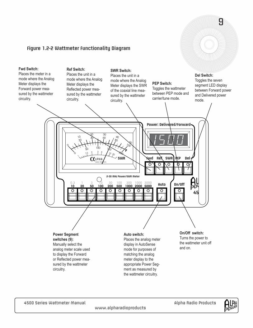
Fwd Switch:Places the meter in a mode where the Analog Meter displays the Forward power mea-sured by the wattmeter circuitry.
Ref Switch:Places the unit in a mode where the Analog Meter displays the Reflected power mea-sured by the wattmeter circuitry.
Power Segment switches (9):Manually select the analog meter scale used to display the Forward or Reflected power mea-sured by the wattmeter circuitry.
SWR Switch:Places the unit in a mode where the Analog Meter displays the SWR of the coaxial line mea-sured by the wattmeter circuitry.
Auto switch:Places the analog meter display in AutoSense mode for purposes of matching the analog meter display to the appropriate Power Seg-ment as measured by the wattmeter circuitry.
PEP Switch:Toggles the wattmeter between PEP mode and carrier/tune mode.
On/Off switch:Turns the power to the wattmeter unit off and on.
Del Switch:Toggles the seven segment LED display between Forward power and Delivered power mode.
Figure 1.2-2 Wattmeter Functionality Diagram
Alpha Radio Products 4500 Series Wattmeter Manualwww.alpharadioproducts
10
1.2 4510 & 4520 Front Panel Layout and Functions
All functions and modes of the 4510 & 4520 are accessible from the front panel using sixteen switches that control the various settings of the unit. Each switch has a built-in LED indicator light that informs the operator of the switch status. There are also two me-ters that display the measured information: a four inch analog meter with different meter scales, and a seven segment, 4 digit LED display. A description of the features found on the front panel is displayed in Figure 1.2-1 and Figure 1.2-2 on the previous pages.
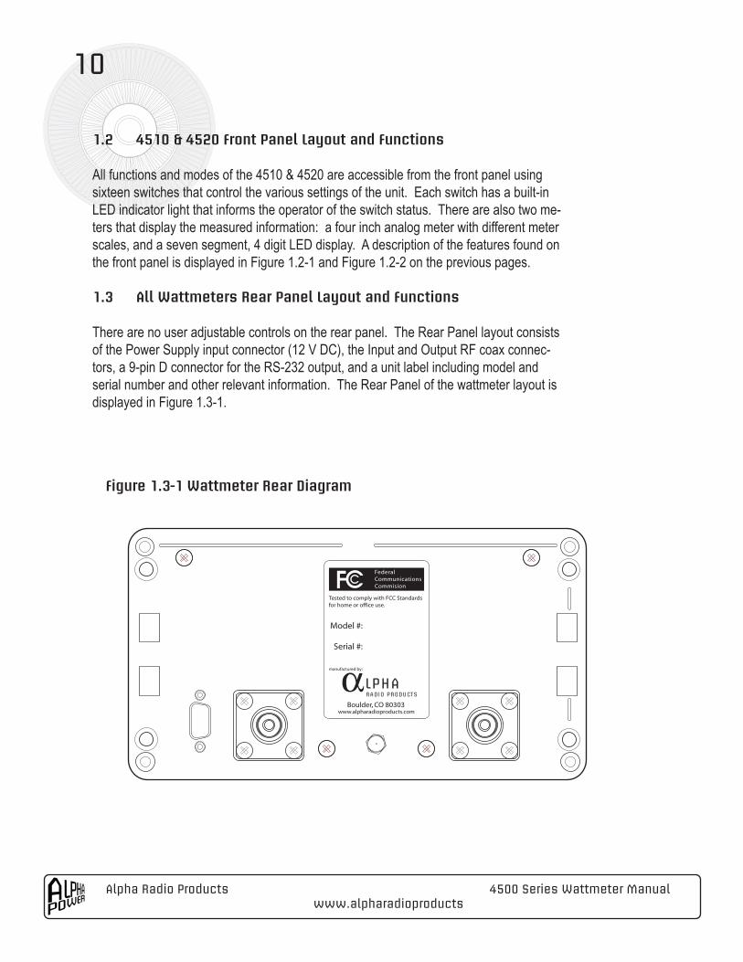
1.3 All Wattmeters Rear Panel Layout and Functions
There are no user adjustable controls on the rear panel. The Rear Panel layout consists of the Power Supply input connector (12 V DC), the Input and Output RF coax connec-tors, a 9-pin D connector for the RS-232 output, and a unit label including model and serial number and other relevant information. The Rear Panel of the wattmeter layout is displayed in Figure 1.3-1.
Figure 1.3-1 Wattmeter Rear Diagram
4500 Series Wattmeter Manual Alpha Radio Products www.alpharadioproducts
11
1.4 Internal Controls and FunctionsThere are no internal controls or user-serviceable parts inside any ARP wattmeter.
NOTE!!Opening the unit will void the manufacturer’s Warranty and may result in inaccurate readings, reduced accuracy, and partial or total electrical failure of the unit. Any dam-age or problems resulting from opening the unit are not covered by the Warranty.
1.5 Connecting the WattmeterPlace the wattmeter in a location with access to the appropriate AC power source such that the front of the unit can be easily viewed by the operator and the front panel controls are comfortably within reach. Since there are no user adjustable controls on the Rear Panel, once all of the cables are connected, the operator will not need access to the back panel to use any functions or features of the unit.
1.5.1 Adjusting the Analog Meter on the 4510 & 4520 After unpacking the wattmeter, set the unit on a level surface and observe the needle indicator in the analog meter before making any connections to the unit. The needle on the meter should rest directly over the “zero” values on the upper scale on the face of the analog meter. If the needle is not directly over the “zero” mark on the scale, carefully insert a small jeweler’s flathead screwdriver into the meter adjustment hole directly under the analog meter face and adjust the needle until it rests directly over the “zero” value. This will ensure that the analog meter performs within the factory specification.
1.5.2 Connecting the Power Supply (all models)The wattmeter is supplied with a Power Supply that is designed to operate from a 100-240 Volt 50-60 Hz AC power source. Attached to the Power Supply is a two-wire cable with a small barrel connector on the end that should be plugged into the recessed male barrel connector receptacle on the back of the meter labeled “12 V DC”.
NOTE!!Since the power output of the supply is DC, the power cable, the barrel connector, and the recessed male connector on the wattmeter are polarized. Although the unit is protected against reverse polarity connection, any tampering or changes to the power cube cable or the barrel connector could lead to damage to or failure of the unit that will not be covered under the Warranty.
After connecting the barrel connector to the back of the meter and plugging in the power cube, momentarily depress the “On/Off” switch on the far lower right hand side of the front panel to turn the unit On. A small LED within the On/Off switch will be illuminated,
Alpha Radio Products 4500 Series Wattmeter Manualwww.alpharadioproducts
12
confirming that the wattmeter is now powered on. A blinking self-test sequence briefly illuminates each of the switch LEDs. The seven segment, four-character-plus- decimal LED display should indicate between 0000 to 0003 (if no RF power is present), the analog meter illumination will be enabled, and the unit will issue a short audible tone. By default, the unit powers up in the Auto Power Sense mode, displaying SWR on the analog meter and PEP Delivered power on the seven segment display. The 4505 and 4515 of course do not have LED displays or switches. Once you connect the power and the serial cable to a faceless wattmeter the unit is on and it will be streaming data.
1.5.3 Connecting the RF Coaxial Cables (all models)Since the wattmeter automatically senses the direction of RF flow through the meter, the RF source (transmitter) and the RF load (antenna) may be interchangeably1 connected to either of the two RF connectors on the back of the unit. First, securely attach the 50 ohm coax from the antenna (or from a separate antenna switch if one is used to select from among various antennas) to either RF connector on the back of the wattmeter. Next, securely attach the 50 ohm coax cable from the output stage of the HF transceiver or amplifier to the other coaxial connector on the back of the wattmeter. Keeping this cable length as short as practical is strongly recommended to reduce line losses and standing waves. Carefully inspect, tighten, and (if needed) clean coaxial plugs every time they are mated to the unit to insure long life from the wattmeter coax connectors.
To fully realize the accuracy of the wattmeter, use only good quality coaxial cable for all RF connections. To ensure long life for the standard SO-239 “UHF” style connectors on the back of the wattmeter, it is good practice to inspect the male connectors on the end of the coax cable before mating them with the connectors on the back of the wattmeter. When using coax with newly installed PL-259 “UHF” style connectors, carefully inspect the center “pin” of each PL-259 and remove any excess solder using a fine grade file as well as any remnants of solder flux.
NOTE!!Use only a 50 Ohm coaxial cable (such as RG-58, RG-8 or equivalents) to connect the wattmeter both to your RF source and to your antenna(s). Alpha strongly recommends the use of proper grounding throughout your installation and use of RG-8 type of coax (or equivalent) to minimize cable loss, to reduce the risk of coax cable dielectric break-down, and to minimize radiation and electrical hazards to the operator. As an added safety precaution, Alpha urges the use of RG-8 or equivalent for any installation where the RF output level of the transmitter is greater than 200 watts.
The wattmeter is supplied with standard UHF (or SO-239) connectors but the unit is also available with optional N-type connectors. Please call the factory for more details. There is no requirement for both connectors to be of the same type.
1While the meter features interchangeability, factory calibration is performed with the load (output) connected to the RF connector nearer the D connector, and therefore, better accuracy is expected with this configuration.
4500 Series Wattmeter Manual Alpha Radio Products www.alpharadioproducts
13
1.5.4 Connecting the 9-pin D Connector (all models)The power output levels, reflected power level, SWR, and other engineering information calculated by the wattmeter are available as a serial data stream via the 9-pin D connec-tor located on the back of the wattmeter. The connector is configured to provide a serial data stream to the user in RS-232 format over a “straight-through” 9-pin male-female RS-232 cable. Information on using the SoftMeter Windows based application to display some of the wattmeter information output via this connector is contained in Section 1.7. Additional information on connecting an RS-232 cable to wattmeter is contained in Sec-tion 1.8. The format of the data stream output from the wattmeter is provided in Appendix D.
1.5.5 Powering On the 4510 & 4520Momentarily depressing the On/Off switch supplies the 12-volt power to the wattmeter circuitry. When 12 Volts DC power is applied to the wattmeter, the LED on the On/Off switch remains illuminated. When the switch is momentarily pressed again, 12 volt power is disabled to the wattmeter and the LED on the On/Off switch is no longer illuminated.
The 4510 and 4520 feature a “sleep” mode. When the unit senses no RF presence on the coax line for a period of approximately six minutes, the wattmeter turns off the display lights of the analog meter, the illumination of the seven segment LED display, and all the switch LEDs except for the On/Off switch red LED. The unit will instantly awaken and turn all lights back on when any RF power is detected by the unit without any operator inter-vention required. All modes set prior to “sleep” will be restored as they were prior to the unit entering sleep mode. Also, depressing any switch (except the On/Off switch) returns the unit to awake mode.
To turn the 4510 or 4520 (but not the AC power supply) off, momentarily depress the On/Off switch.
1.5.6 Powering On the 4505 & 4515As soon as the 4505 or 4515 is plugged into its power supply the wattmeter is “on”. To turn “off” the wattmeter you will need to disconnect it from its power supply or disconnect the power supply from the AC outlet.
Alpha Radio Products 4500 Series Wattmeter Manualwww.alpharadioproducts
14
NOTE!!When the On/Off switch is “Off or the wattmeter is disconnected from the power supply, the power cube will continue to draw AC power and provide 12 volts DC power to the wattmeter. Therefore, if you plan to be away from your station for any period of time, you might want to connect the power supply to a wall outlet or AC power source that can be separately controlled in order to control the AC power applied to the power cube. This would be considered an energy conservation and a safety measure, and it may extend the service life of the power cube.
1.6 Operation of the 4510 & 4520
1.6.1 Selecting RF operating mode – PEP or Tune To select the RF operating mode, the operator need only momentarily depress the “PEP” switch to place the meter in either the “PEP” mode or the “Carrier/Tune” mode. The “PEP” switch is the second switch from the right of the front panel underneath the LED display. When the PEP switch is illuminated, the wattmeter is in the PEP mode. When it is not illuminated, it is in the Carrier/Tune mode. When first powered on, the unit defaults to the PEP mode. The PEP mode is the recommended mode for most voice and CW operation.
Generally, the Carrier/Tune mode should be used when setting up a station or antenna configuration, evaluating SWR under a fixed load environment, or tuning up an exciter, amplifier or antenna tuner. A brief description of the algorithms used for each of the two modes is provided in Table 1.6.1-1.
Table 1.6.1-1 Mode / Algorithm / Application
Mode Algorithm Intended ApplicationTune/Carrier Measures 32 discrete samples to
calculate an average value for a given reading.
Making lab-quality measurements of RF Power or SWR using constant signal or “key down” operating scenario. Use this mode for tuning an exciter or output stage, or when matching an output stage to an an-tenna using an antenna matching network.
PEP Measures 497 discrete samples and uses the 6 - highest sample values to calculate an average value for a given reading.
Peak Power measurements of CW (morse code), SSB, or RTTY signals. Use this mode for normal operation after station tune-up.
One benefit a station operator gains from the full scale accuracy of the wattmeter is that the operator can set up a transmit station at a low power level (only about 0.25 watts of forward power is required for the 4505 & 4510 and about 0.5 watts of forward power is required for the 4515 & 4520), and once SWR is minimized, the operator can switch the
4500 Series Wattmeter Manual Alpha Radio Products www.alpharadioproducts
15
station to full power without having to re-match the antenna network. Meter scaling errors common in other Power/SWR meters often require the station operator to readjust the antenna-transmitter match after switching from low power levels to high power levels. Additionally, the dual analog/digital display capability of the wattmeter permits the opera-tor to simultaneously view Forward or Delivered power on the digital display, and SWR on the analog meter. This allows verification that both the RF source and the RF load are operating correctly.
1.6.2 Selecting the Analog Meter Display FunctionDuring operation, the wattmeter simultaneously measures all four functions performed by the unit – Delivered Power, Forward Power, Reflected Power, and SWR. At any one time, any one of these measurements except Delivered power can be displayed on the analog meter. The initial Power On default mode sets the analog meter display to SWR in the PEP mode.
To select which measurement is to be displayed on the analog meter, there are three switches located to the right of the meter that determine which measurement is to be displayed. The switches are:
· “Fwd” displays Forward Power measurement· “Ref” displays Reflected Power measurement· “SWR” displays SWR measurement
Depressing any one of the three switches will illuminate that switch and deselect which-ever of the other switches were previously selected. Selection among these switches will not affect any other switch selections or default modes of the wattmeter.
NOTE!!The analog meter does not display Delivered power. It will not be affected by the state of the “Del” switch located to the right of the PEP switch. The Del switch only controls the power displayed on the seven segment LED.
1.6.3 Interpreting the Analog Meter Scaling on the 4510To provide reasonable accuracy in reading the analog meter display for the various func-tions and across the broad power range of the 4510, three scales have been provided on the analog meter.
The top scale (0-10) on the analog meter should be used to read measured Power (For-ward or Reflected) across four of the nine Power Segments using a “0 to 10” scale. . The “10” value should be interpreted as 1, 10, 100, or 1,000 watts, depending on the Power Segment selected. The applicable Power Segments for the top scale are summarized in
Alpha Radio Products 4500 Series Wattmeter Manualwww.alpharadioproducts
16
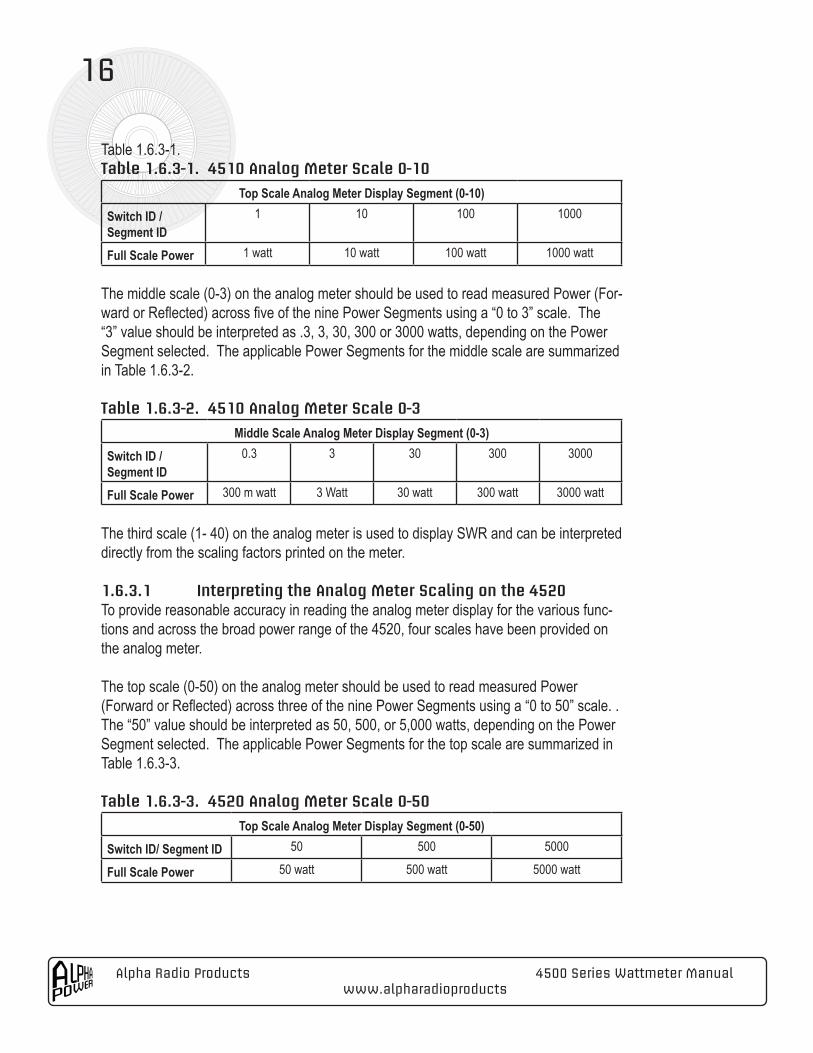
Table 1.6.3-1.Table 1.6.3-1. 4510 Analog Meter Scale 0-10
Top Scale Analog Meter Display Segment (0-10)Switch ID / Segment ID
1 10 100 1000
Full Scale Power 1 watt 10 watt 100 watt 1000 watt
The middle scale (0-3) on the analog meter should be used to read measured Power (For-ward or Reflected) across five of the nine Power Segments using a “0 to 3” scale. The “3” value should be interpreted as .3, 3, 30, 300 or 3000 watts, depending on the Power Segment selected. The applicable Power Segments for the middle scale are summarized in Table 1.6.3-2.
Table 1.6.3-2. 4510 Analog Meter Scale 0-3
Middle Scale Analog Meter Display Segment (0-3)Switch ID / Segment ID
0.3 3 30 300 3000
Full Scale Power 300 m watt 3 Watt 30 watt 300 watt 3000 watt
The third scale (1- 40) on the analog meter is used to display SWR and can be interpreted directly from the scaling factors printed on the meter.
1.6.3.1 Interpreting the Analog Meter Scaling on the 4520To provide reasonable accuracy in reading the analog meter display for the various func-tions and across the broad power range of the 4520, four scales have been provided on the analog meter.
The top scale (0-50) on the analog meter should be used to read measured Power (Forward or Reflected) across three of the nine Power Segments using a “0 to 50” scale. . The “50” value should be interpreted as 50, 500, or 5,000 watts, depending on the Power Segment selected. The applicable Power Segments for the top scale are summarized in Table 1.6.3-3.
Table 1.6.3-3. 4520 Analog Meter Scale 0-50
Top Scale Analog Meter Display Segment (0-50)Switch ID/ Segment ID 50 500 5000
Full Scale Power 50 watt 500 watt 5000 watt
4500 Series Wattmeter Manual Alpha Radio Products www.alpharadioproducts
17
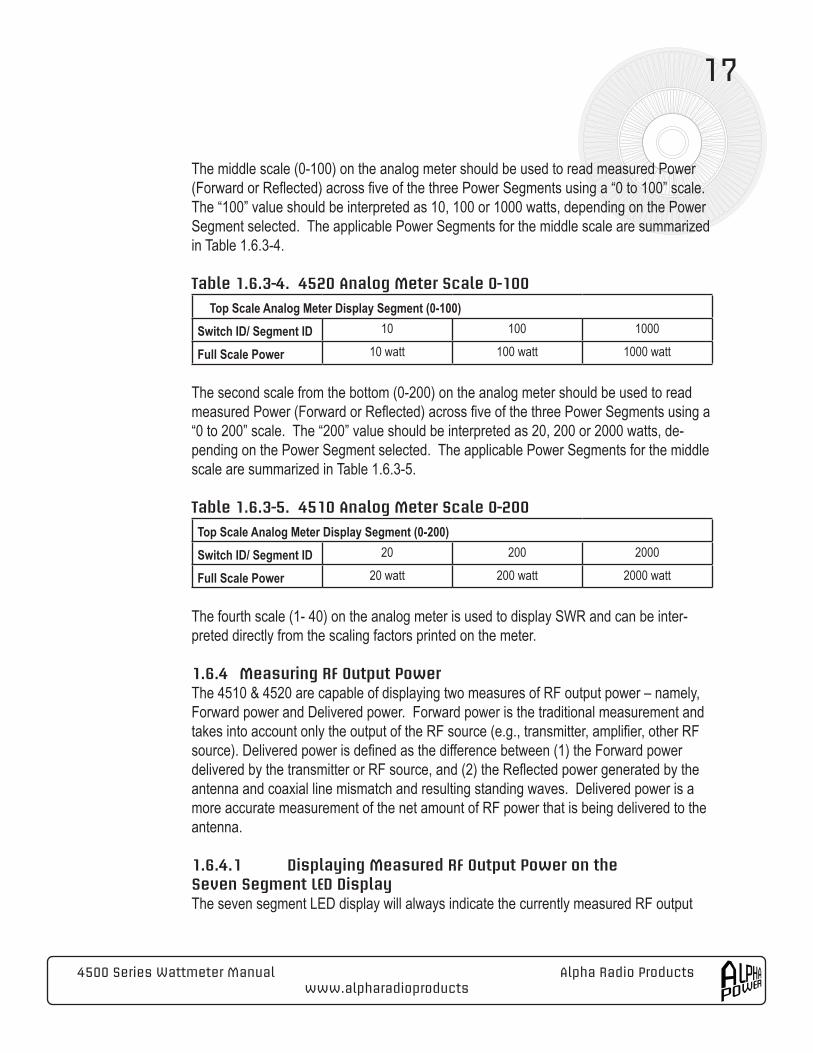
The middle scale (0-100) on the analog meter should be used to read measured Power (Forward or Reflected) across five of the three Power Segments using a “0 to 100” scale. The “100” value should be interpreted as 10, 100 or 1000 watts, depending on the Power Segment selected. The applicable Power Segments for the middle scale are summarized in Table 1.6.3-4.
Table 1.6.3-4. 4520 Analog Meter Scale 0-100
Top Scale Analog Meter Display Segment (0-100)Switch ID/ Segment ID 10 100 1000
Full Scale Power 10 watt 100 watt 1000 watt
The second scale from the bottom (0-200) on the analog meter should be used to read measured Power (Forward or Reflected) across five of the three Power Segments using a “0 to 200” scale. The “200” value should be interpreted as 20, 200 or 2000 watts, de-pending on the Power Segment selected. The applicable Power Segments for the middle scale are summarized in Table 1.6.3-5.
Table 1.6.3-5. 4510 Analog Meter Scale 0-200
Top Scale Analog Meter Display Segment (0-200)Switch ID/ Segment ID 20 200 2000
Full Scale Power 20 watt 200 watt 2000 watt
The fourth scale (1- 40) on the analog meter is used to display SWR and can be inter-preted directly from the scaling factors printed on the meter.
1.6.4 Measuring RF Output PowerThe 4510 & 4520 are capable of displaying two measures of RF output power – namely, Forward power and Delivered power. Forward power is the traditional measurement and takes into account only the output of the RF source (e.g., transmitter, amplifier, other RF source). Delivered power is defined as the difference between (1) the Forward power delivered by the transmitter or RF source, and (2) the Reflected power generated by the antenna and coaxial line mismatch and resulting standing waves. Delivered power is a more accurate measurement of the net amount of RF power that is being delivered to the antenna.
1.6.4.1 Displaying Measured RF Output Power on the Seven Segment LED DisplayThe seven segment LED display will always indicate the currently measured RF output
Alpha Radio Products 4500 Series Wattmeter Manualwww.alpharadioproducts
18
power. The seven segment LED will display either Forward power or Delivered power in watts, depending on the selection of the Del switch. Depressing the “Del” switch will illuminate the corresponding switch LED and the seven segment display will indicate Delivered power.
1.6.4.2 Displaying Measured RF Output Power on the Analog MeterThe analog meter will display Forward power but not Delivered power. The Forward Power measured by the wattmeter is displayed on the analog meter by momentarily depressing the switch marked “Fwd”. Like all the front panel switches, the LED for this switch remains illuminated while the analog meter is in this mode. Depending on which Power Segment switch is illuminated (whether selected manually or by AutoSense as de-scribed in Section 1.6.7.2), the appropriate top scale or middle scale of the analog meter should be used to interpret the Forward Power level measured by the unit. Section 1.6.7 contains general information on selecting the correct forward power range for the analog meter display.
1.6.5 Displaying Measured Reflected Power on the Analog MeterThe Reflected Power measured by the wattmeter is displayed by momentarily depressing the switch marked “Ref”. Like all the front panel switches, the LED for this switch remains illuminated while the meter is in this mode. Depending on which Power Segment switch is illuminated (whether selected manually or by AutoSense as described in Section 1.6.9.2), the appropriate top scale or middle scale of the analog meter should be used by the operator to read the Reflected Power level measured by the unit.
1.6.6 Displaying Measured SWR on the Analog MeterThe SWR measured by the wattmeter is displayed by momentarily depressing the switch marked “SWR”. Like all the front panel switches, the LED for this switch remains illumi-nated while the meter is in this mode. The operator can then read the measured VSWR of the line under load using the bottom scale of the analog meter.
1.6.7 Selecting the Correct Power SegmentThe 4510 operates continuously from 300 milliwatts to 3 kilowatts and the 4520 oper-ates continuously from 1 watt to 5 kilowatts without the use of any additional plug-in devices. Because of the practical limitations of accurately interpreting measured values displayed on a single analog meter over such a broad power range, the power range has been parsed into nine discrete segments for meter scaling and display purposes. The measured power (Forward and Reflected) can then be more accurately displayed on the analog meter for each of the nine segments.
4500 Series Wattmeter Manual Alpha Radio Products www.alpharadioproducts
19
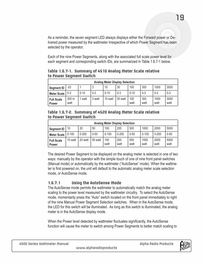
As a reminder, the seven segment LED always displays either the Forward power or De-livered power measured by the wattmeter irrespective of which Power Segment has been selected by the operator.
Each of the nine Power Segments, along with the associated full scale power level for each segment and corresponding switch IDs, are summarized in Table 1.6.7-1 below.
Table 1.6.7-1. Summary of 4510 Analog Meter Scale relative to Power Segment Switch
Analog Meter Display SelectionSegment ID .03 1 3 10 30 100 300 1000 3000
Meter Scale 0-3 0-10 0-3 0-10 0-3 0-10 0-3 0-3 0-3
Full Scale Power
300 m watt
1 watt 3 watt 10 watt 30 watt 100 watt
300 watt
1000 watt
3000 watt
Table 1.6.7-2. Summary of 4520 Analog Meter Scale relative to Power Segment Switch
Analog Meter Display SelectionSegment ID 10 20 50 100 200 500 1000 2000 5000
Meter Scale 0-100 0-200 0-50 0-100 0-200 0-50 0-100 0-200 0-50
Full Scale Power
10 watt 20 watt 50 watt 100 watt
200 watt
500 watt
1000 watt
2000 watt
5000 watt
The desired Power Segment to be displayed on the analog meter is selected in one of two ways: manually by the operator with the simple touch of one of nine front panel switches (Manual mode) or automatically by the wattmeter (“AutoSense” mode). When the wattme-ter is first powered on, the unit will default to the automatic analog meter scale selection mode, or AutoSense mode.
1.6.7.1 Using the AutoSense ModeThe AutoSense mode permits the wattmeter to automatically match the analog meter scaling to the power level measured by the wattmeter circuitry. To select the AutoSense mode, momentarily press the “Auto” switch located on the front panel immediately to right of the nine Manual Power Segment Selection switches. When in the AutoSense mode, the LED for this switch will be illuminated. As long as this switch is illuminated, the analog meter is in the AutoSense display mode.
When the Power level detected by wattmeter fluctuates significantly, the AutoSense function will cause the meter to switch among Power Segments to better match scaling to
Alpha Radio Products 4500 Series Wattmeter Manualwww.alpharadioproducts
20
the measured power level. AutoRanging can be observed when the illuminated LED for each Power Segment switch is turned on or off as the wattmeter is detecting power levels within that segment. The wattmeter continuously monitors to see if the measured power is within the currently selected range. If it is above the maximum for the current range, it im-mediately goes to the appropriate full-scale range. If the power is within range of a lower full-scale value, the meter “dwells” at the current scale for a couple of seconds before dropping to the new lower scale. This feature avoids the meter “bouncing” between scales when power is varying, such as during SSB radio communications.
This AutoSense feature has both a practical and a reliability benefit. AutoRanging as-sists the operator in keeping the analog meter deflection roughly in the center third of the desired segment the meter scale, making accurate reading of the power levels easier. It also reduces overall meter movement.
AutoSense mode has a built in response delay feature useful during station tune-up. The feature provides a less “jumpy” analog meter display when the RF source is chang-ing power levels. This response delay feature operates such that if the power increases beyond the currently auto-selected full-scale maximum, the next higher power segment is immediately chosen. Conversely, if the measured signal decreases such that a lower range would be more appropriate, the wattmeter “hangs” at the higher scale for up to two seconds. By way of example, if a 100 watt transmitter is being “dipped and loaded” using the analog meter, and the RF source power is fluctuating between 5 and 75 watts, the analog meter will “hang” on the 100 watt scale during the tune-up procedure. Until station configuration becomes quite stable, and the operator is confident that the measured Power levels are within the 15% of the edge of each segment boundary (e.g., for the 100 to 300 watt segment, expected Power levels should be between roughly 115 and 255 watts), Alpha Radio Products recommends that you operate the meter in the AutoSense mode. When the unit is “on”, and there is no discernible power output mea-sured by the unit, the wattmeter will illuminate the lowest power segment light even when the unit is in the AutoSense mode. Detection of any RF power from the RF source will immediately return the unit to normal AutoSense operation.
1.6.7.2 Using the Manual ModeMomentarily depressing any of the nine Segment switches or the pressing the already illuminated “Auto” switch will return the wattmeter to the Manual mode. If the AutoSense mode is turned off without selecting a segment manually, the wattmeter will default to the last setting selected in the AutoSense mode.
The Manual mode permits the operator to select and lock the wattmeter analog meter in
4500 Series Wattmeter Manual Alpha Radio Products www.alpharadioproducts
21
one of nine Power Segment ranges. This is most useful when the operator is confident of the expected power level to be measured and wants the analog meter deflection to stay within a certain part of the meter scale.
The nine Power Segment selection switches are located immediately underneath the ana-log meter face and are used to select a specific Power Segment. Momentarily depressing one of these switches selects the specified Power Segment, and illuminates a small LED on that switch to mark that segment as selected for meter display purposes.
Pressing any other Power Segment switch deselects the original illuminated switch and switches the Power Segment to the most recently depressed switch. Power Segment switches need not be pressed sequentially to change levels, and the operator can ran-domly select the desired Power Segment manually as frequently as needed.
If a power greater than the currently selected full-scale value is applied, the meter indi-cates full scale. No damage occurs due to meter overshoot. For example, if the 4510 is in the Fwd mode, and 0.3 Watt manual range is selected, but 3 kilowatts of RF energy is applied, the analog meter will go full scale but no meter damage will occur. The seven segment display will continue to show the accurate RF output level.
1.7 Windows Monitoring ApplicationThe SoftMeter software ships with all models of wattmeters. SoftMeter is a Windows-based application that permits monitoring all of the functions summarized above simulta-neously. The application requires that the wattmeter is connected to a personal computer running Windows 98, ME, 2000 Professional, or XP via the 9-pin D connector (using a RS-232 serial port) on the back of the wattmeter. The cable should be a “straight through” shielded cable. The supplied Windows application requires 10 Megabytes of free hard disk space, 256 Megabytes of RAM, and an unused Serial Port on the computer.
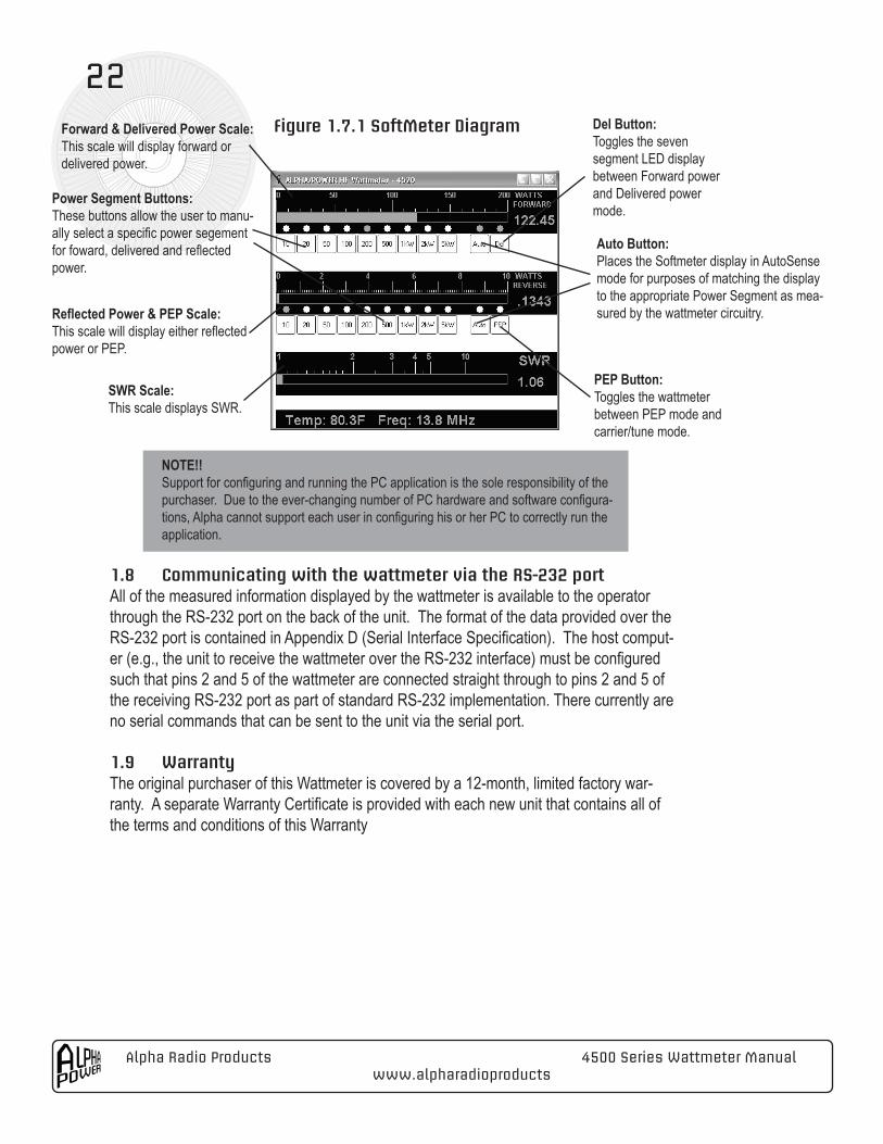
For the 4505 and 4515 model wattmeters the SoftMeter software is the only method by which a user can access their wattmeter’s functionality. The Softmeter’s interface is simi-lar to that of the physical display found on the 4510 and 4520; it expands the users ability to simultaneously monitor all measurements the wattmeter is capable of making. See figure 1.7.1 for details.
Alpha Radio Products 4500 Series Wattmeter Manualwww.alpharadioproducts
22
NOTE!!Support for configuring and running the PC application is the sole responsibility of the purchaser. Due to the ever-changing number of PC hardware and software configura-tions, Alpha cannot support each user in configuring his or her PC to correctly run the application.
1.8 Communicating with the wattmeter via the RS-232 portAll of the measured information displayed by the wattmeter is available to the operator through the RS-232 port on the back of the unit. The format of the data provided over the RS-232 port is contained in Appendix D (Serial Interface Specification). The host comput-er (e.g., the unit to receive the wattmeter over the RS-232 interface) must be configured such that pins 2 and 5 of the wattmeter are connected straight through to pins 2 and 5 of the receiving RS-232 port as part of standard RS-232 implementation. There currently are no serial commands that can be sent to the unit via the serial port.
1.9 WarrantyThe original purchaser of this Wattmeter is covered by a 12-month, limited factory war-ranty. A separate Warranty Certificate is provided with each new unit that contains all of the terms and conditions of this Warranty
Auto Button:Places the Softmeter display in AutoSense mode for purposes of matching the display to the appropriate Power Segment as mea-sured by the wattmeter circuitry.
PEP Button:Toggles the wattmeter between PEP mode and carrier/tune mode.
Del Button:Toggles the seven segment LED display between Forward power and Delivered power mode.
Power Segment Buttons:These buttons allow the user to manu-ally select a specific power segement for foward, delivered and reflected power.
Forward & Delivered Power Scale:This scale will display forward or delivered power.
Reflected Power & PEP Scale:This scale will display either reflected power or PEP.
SWR Scale:This scale displays SWR.
Figure 1.7.1 SoftMeter Diagram
4500 Series Wattmeter Manual Alpha Radio Products www.alpharadioproducts
23
Appendix A Troubleshooting
Unit will not power onCheck DC power supply voltage and the polarity of the power supply. The power supply supplied by the Factory provides 12V DC voltage, using the tip as the positive (+) pole, and the barrel as the negative (-) pole. If you are using another power source, be sure you confirm that the polarity of coaxial connector is consistent with this configuration. The power connector on the rear of the wattmeter is 5.5 x 2.5 mm coaxial power jack.
If both DC voltage and connector polarity are correct, check for serial data on the 9-pin D connector. If serial data is present, then Display board is damaged. Unit must be returned to factory for repair.
If no serial data is present, then an internal part failure has occurred. Unit must be re-turned to factory for repair.
High SWR always indicatedCheck connection between wattmeter and antenna/load. One or more faulty coax cables (open or short) may cause this. If an antenna switch is used, check the continuity of the antenna switch as well.
Check connectors are all tight. Check for corroded or physically damaged center contacts on coax connectors. If in doubt about the integrity of the coax connectors, try replacing all coax cables. If wattmeter coax connectors are damaged, replace with new ones.
Erratic RS-232 Operation at high power At higher RF power levels, it is common for RF power to couple into the RS-232 cable connecting the wattmeter to the computer. This coupled power often generates the noise that degrades the data stream received by computer and results in irrelevant or erroneous data being displayed on the computer screen. Using a shielded RS-232 cable, carefully routing the RS-232 cable, and following good station grounding practices (including both the PC as well as the overall station) will help avoid this coupling.
Alpha Radio Products 4500 Series Wattmeter Manualwww.alpharadioproducts
24
Appendix B Wattmeter Specifications
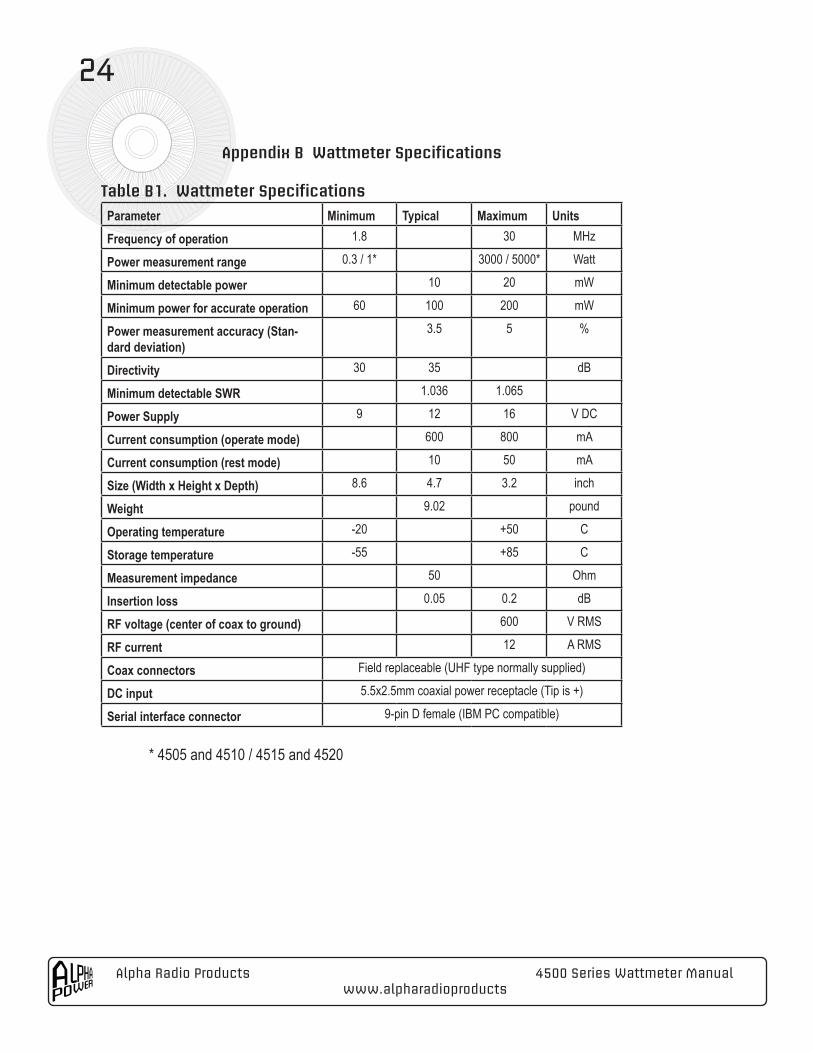
Table B1. Wattmeter Specifications
Parameter Minimum Typical Maximum UnitsFrequency of operation 1.8 30 MHz
Power measurement range 0.3 / 1* 3000 / 5000* Watt
Minimum detectable power 10 20 mW
Minimum power for accurate operation 60 100 200 mW
Power measurement accuracy (Stan-dard deviation)
3.5 5 %
Directivity 30 35 dB
Minimum detectable SWR 1.036 1.065
Power Supply 9 12 16 V DC
Current consumption (operate mode) 600 800 mA
Current consumption (rest mode) 10 50 mA
Size (Width x Height x Depth) 8.6 4.7 3.2 inch
Weight 9.02 pound
Operating temperature -20 +50 C
Storage temperature -55 +85 C
Measurement impedance 50 Ohm
Insertion loss 0.05 0.2 dB
RF voltage (center of coax to ground) 600 V RMS
RF current 12 A RMS
Coax connectors Field replaceable (UHF type normally supplied)
DC input 5.5x2.5mm coaxial power receptacle (Tip is +)
Serial interface connector 9-pin D female (IBM PC compatible) * 4505 and 4510 / 4515 and 4520
4500 Series Wattmeter Manual Alpha Radio Products www.alpharadioproducts
25
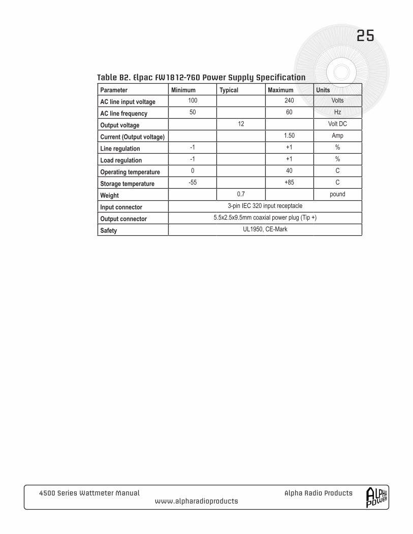
Table B2. Elpac FW1812-760 Power Supply Specification
Parameter Minimum Typical Maximum UnitsAC line input voltage 100 240 Volts
AC line frequency 50 60 Hz
Output voltage 12 Volt DC
Current (Output voltage) 1.50 Amp
Line regulation -1 +1 %
Load regulation -1 +1 %
Operating temperature 0 40 C
Storage temperature -55 +85 C
Weight 0.7 pound
Input connector 3-pin IEC 320 input receptacle
Output connector 5.5x2.5x9.5mm coaxial power plug (Tip +)
Safety UL1950, CE-Mark
Alpha Radio Products 4500 Series Wattmeter Manualwww.alpharadioproducts
26
Appendix C Changing the Back Panel RF Coaxial Connectors
The coaxial connectors are field replaceable. If the connectors become damaged, or if different style connectors are to be installed, connectors may be replaced by the user in the field. This replacement activity is designed to occur without any requirement to disas-semble the wattmeter other than removal of the two affected coaxial antenna connectors.
THERE ARE NO USER SERVICEABLE PARTS INSIDE THE UNIT. OPENING THE UNIT BY SEPARATING THE WATTMETER FRONT PANEL FROM ITS BACK PANEL MAY DAMAGE THE UNIT OR AFFECT ITS CALIBRATION OROPERATION, AND WILL VOID THE WARRANTY.
The coaxial connectors may be replaced using the following procedure:
1. Disconnect the unit completely from the installation. Turn it face downward on a soft surface, tilting the unit so that it rests on the carrying handles. 2. Using a #2 Phillips screwdriver, unscrew and remove the four stainless steel machine screws and lock washers for each of the connector(s) being removed. Set the screws and lock washers aside. If one is lost, it should be replaced only with an identical stainless steel screw and lock washer.
3. Remove the connector(s) by drawing it straight up away from the wattmeter. The connector may require some slight force to remove it from its socket connec-tion on the wattmeter Printed Circuit Board (PCB).
4. Before installing a new connector, inspect the mating contact using a flashlight for the connector center pin, and the chassis area around the connector. If neces-sary, clean these surfaces using a Q-tip and some alcohol.
5. To install the new connector, reverse the above procedure.
6. Gently press the connector into the socket connection on the wattmeter PCB. The connector should fit snugly into the PCB. Align the screw mounting holes of the new connector with those already drilled in the back of the wattmeter.
7. Secure the new connector using the factory supplied screws. The screws are stainless steel machine types, 8-32 x 5/16”. Make sure the screws are tight before applying RF power.
4500 Series Wattmeter Manual Alpha Radio Products www.alpharadioproducts
27
Appendix D Serial Interface Specification
The serial port continuously outputs data at 38,400 bps, using 8 data bits, 1 stop bit, and no parity (N,8,1). All characters are “human readable”, i.e. they will be displayed as ASCII text if directed to a terminal display program such as “Hyperterm” in Windows.
A complete set of data output for one “measurement”, whether in either PEP or CW mode consists of a data “sentence”. Each sentence is identified with a start, or sentinel, charac-ter ($) and each sentence is subsequently terminated with an end character (*) plus two additional characters (FF). Each sentence is separated by a <carriage return> and <line feed>.
Each sentence consists of seven words and each word in a “sentence” is separated by a comma. The first word in the sentence consists of the Start character <$> followed by the letters <APW> and one of the following numerical sets” <01> or <02>. The numerical sets each indicate a distinct message type. Message type <01> indicates that the 4510 is in Tune/Carrier mode. Message type <02> indicates it is in PEP mode.
A typical First Word in a sentence would appear as follows (including the comma separa-tor):
$APW01,
The next five Data Words represent the following five data fields, respectively: Forward Power (watts), Reflected Power (watts), SWR, Temperature (Degrees F), Estimated Fre-quency (MHz). Each of these “word” fields is separated by a comma.
A typical string of words following the First Word might appear as follows (including the comma separators):
0.240197,0.031695,2.140988,77.900000,3.482099
The above information indicates the following data:
Forward Power: 0.240197 WReflected Power: 0.031695 WSWR: 2.140988Temperature: 77.900000 FFrequency: 3.482099 MHz
Alpha Radio Products 4500 Series Wattmeter Manualwww.alpharadioproducts
28
The Final Word of every Sentence is indicated by a <*> character followed by two ad-ditional characters that currently are fixed as <FF>. Thus, the Final Word in every Sen-tence should appear as follows:
*FF
Immediately after the completion of the Final Word in a Sentence, the wattmeter sends a carriage return and line feed. On a Hyperterm screen, the cursor would drop down one line, and the next character viewed would then be the Sentinel character <$>, indicating a new First Word in the new Sentence.
Two examples of complete Sentences are as follows:
Example 1:
$APW01,0.240459,0.031606,2.137487,78.012496,3.491939,*FF
Mode: Tune/CarrierForward: 0.240459WReflected: 0.031606 WSWR: 2.137487Temp 78.012496 FFreq. 3.491939 MHz.
Example 2:
$APW02,0.256680,0.033417,2.129019,78.012496,4.533681,*FF
Mode: PEPForward: 0.256680 WReflected: 0.033417 WSWR: 2.129019Temp: 78.012496FFreq: 4.533681 MHz.
Additional Notes:
1. The rate at which the sentences are emitted depends on the mode. They are more rapid in Tune/Carrier mode than in PEP mode.
4500 Series Wattmeter Manual Alpha Radio Products www.alpharadioproducts
29
2. Temperature field is the internal temperature of the unit used for temperature compensation. It is NOT ambient or room temperature.
3. The Frequency word field is an estimate, and it is only accurate to +/- 10%. It is the estimate used by the meter for frequency compensation.
4. Delivered Power is a derived value and not a measured value. It is calculated as the difference between Forward and Reflected Power for any given measure-ment.
Alpha Radio Products 4500 Series Wattmeter Manualwww.alpharadioproducts
30
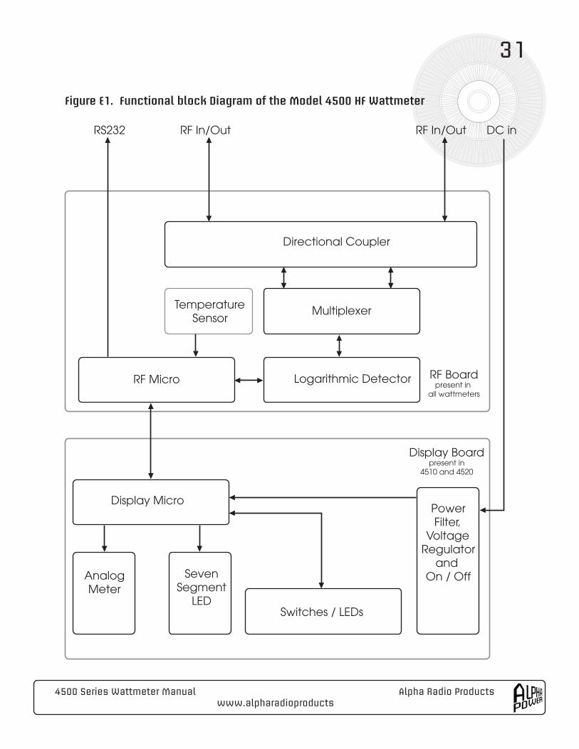
Appendix E Theory of Operation
The 4510 and 4520 HF Wattmeter consists of two circuit boards that pass information between them in order to calculate and display the various parameters measured by the unit, whereas thee 4505 and 4515 have one circuit board each. The functional block diagram for all wattmeters is shown in Figure E1 below.
One circuit board is designated the RF Board and the second one is designated the Dis-play Board. Each board has its own micro-controller, designated RF Micro and Display Micro respectively. The dashed line across the middle of Figure E1 generally illustrates the segregation of functions between the RF Board and the Display Board.
The heart of the wattmeter measurement system is the proprietary high-quality directional coupler located on the RF Board. Specific qualities of the directional coupler include high directivity, very low power dissipation, and the absence of problematic iron-core magnet-ics. The RF signal being sampled passes through this coupler, which produces indepen-dent samples of the forward and reflected waves in the coaxial system. These samples are converted into DC values via a wide-range integrated logarithmic detector. The sampling rate and number of samples/estimate depends on whether the unit is in PEP or Tune/Carrier mode. These DC values are digitized by the RF micro (one of two micro-controllers used in the wattmeter) and converted into the estimates of Forward power, Reflected power and SWR.
To achieve the wattmeter’s full range and degree of accuracy, the RF Micro also calcu-lates an estimate of the Frequency of the RF in the coupler and also measures the tem-perature of the coupler and log detector from an on board temperature sensor. Together, these measurements are used to adjust the raw values calculated by the RF Micro for the effects of temperature and frequency during operation. After adjusting for tempera-ture and frequency, the final estimates of Forward power, Reflected power and SWR are passed from the RF micro to the Display micro over an I2C bus.
The Display micro manages all of the user interface functions of the 4510 and 4520, including routing of signals generated by activation of the various switches. It sets the parameters and the range to be displayed on the Analog meter (whether in AutoSense or Manual mode), drives the seven segment display, and sends a signal to the RF micro when the user toggles the meter between operating modes (PEP/Tune Carrier).
4500 Series Wattmeter Manual Alpha Radio Products www.alpharadioproducts
31
Directional Coupler
TemperatureSensor
Multiplexer
RF Micro Logarithmic Detector
Display Micro
AnalogMeter
SevenSegment
LEDSwitches / LEDs
PowerFilter,
VoltageRegulator
and On / Off
RS232 RF In/Out RF In/Out DC in
RF Boardpresent in
all wattmeters
Display Boardpresent in
4510 and 4520
Figure E1. Functional block Diagram of the Model 4500 HF Wattmeter
Alpha Radio Products 4500 Series Wattmeter Manualwww.alpharadioproducts
32
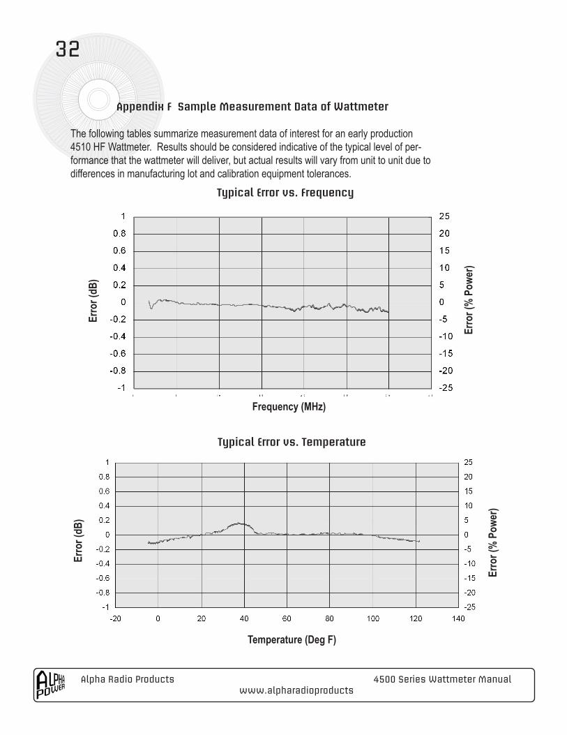
Appendix F Sample Measurement Data of Wattmeter
The following tables summarize measurement data of interest for an early production 4510 HF Wattmeter. Results should be considered indicative of the typical level of per-formance that the wattmeter will deliver, but actual results will vary from unit to unit due to differences in manufacturing lot and calibration equipment tolerances.
Typical Error vs. Frequency
Typical Error vs. Temperature
Erro
r (dB
)
Erro
r (%
Pow
er)
Frequency (MHz)
Erro
r (dB
)
Erro
r (%
Pow
er)
Temperature (Deg F)
4500 Series Wattmeter Manual Alpha Radio Products www.alpharadioproducts
33
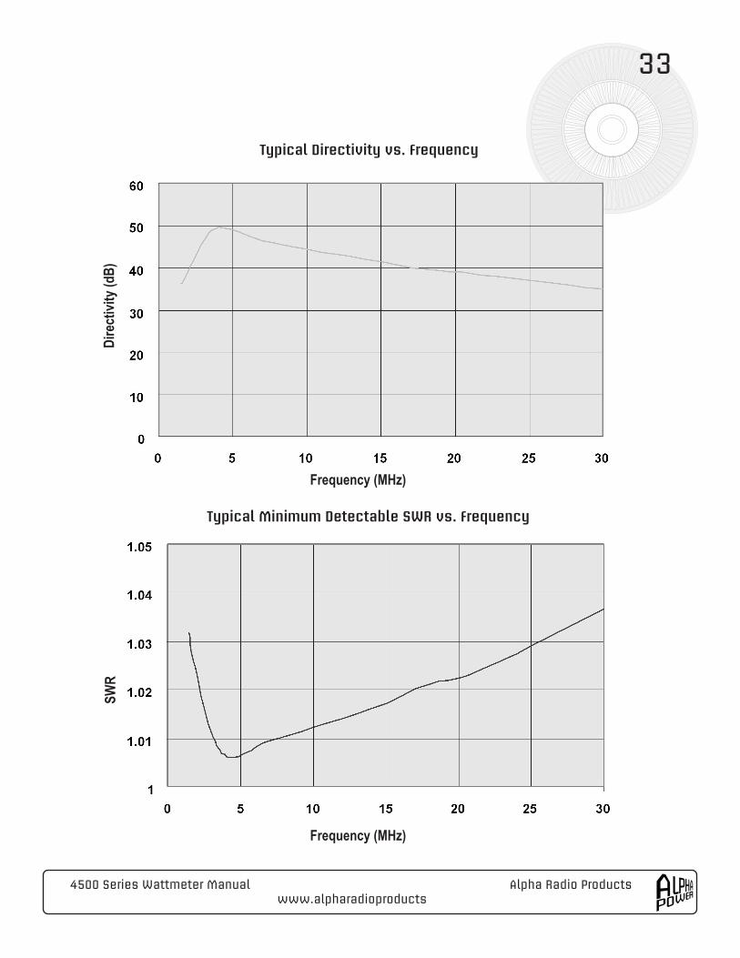
Typical Directivity vs. Frequency
Dire
ctivi
ty (d
B)
Frequency (MHz)
Typical Minimum Detectable SWR vs. Frequency
SWR
Frequency (MHz)