4/5/16 to 4/7/16 - firth · pdf file• 4/5/16 to 4/7/16. ... discussion of the current...
TRANSCRIPT

Keystone MSE Wall Design and Seismic Applications• 4/5/16 to 4/7/16

Topics
1. Product Offerings1. Extensible - Geosynthetic
2. Inextensible – Steel
3. Research, Development and Testing
2. Design Basics and Introduction to Methodologies1. Differences
2. Comparison
3. Introduction to Seismic Design Principles1. Discussion of the current state of design practices
4. Keystone Wall Design Software (Interactive)1. KeyWall
2. KeyDraw
3. KeySystem I Spreadsheet

• First to market and #1 Structural SRW in the World
• Headquarters in Minneapolis, MN– Worldwide
Distribution network
• Leader in Engineering Development of SRW systems
• First segmental retaining wall to market (1986)
• 30 years of innovation: 180+ Patents / Patents Pending
• Keystone Departments
• Engineering• Marketing• Sales• Product development and production
Keystone Introduction

Structural Product Offerings

Products – Country Manor
– Entry Level Structural Product
– Create small freestanding walls, parapet walls, pilasters, columns, and retaining walls.
– 3 unit system with 7 unique face dimensions.
– Units are packaged together as a system to create a random, natural look.
– Three textured sides on each unit.• Used as an exposed end unit or a 90°corner.
– Shouldered pins give multiple setback positions.
• Create vertical or setback walls
1. 2. 3.
Piece # 1 2 3
Height 150 150 150
Width 400/350 300/250 150/100
Depth 250 250 250
Weight (kg) 27 18 11
Pins Shouldered Pins
Note: Unit colors, dimensions, weight, and availability vary by manufacturer.
3 pc. System (1;4;6)System availability varies by manufacturer. Contact directly for details.

Versatility – 3 Sides Textured

Country Manor
Unique
Face
Texture

Country Manor – Parapet Walls

Country Manor Water Feature

Piece # 1 2
Height 200 200
Width 455 455
Depth 533 533
Weight (kg) 52 56
Pins Straight Pins –2/unit
0.091 m2 per unit
Note: Unit colors, dimensions, weight, and availability vary by manufacturer.
1. TRI-PLANE 2. STRAIGHT
Keystone
Standard
Product – Standard Unit

Product – Standard Unit
• First Segmental wall unit developed
• Early gravity applications, still best option for gravity wall applications
• Later geogrid introduced for taller walls
• 30 years of unit evolution
• Development of specialty applications for taller gravity walls
• ICC-ES report ESR-2113, ICC-ES is a subsidiary of International Code Council. – Evaluation service for independent verification of compliance to
the International Building Code (IBC)
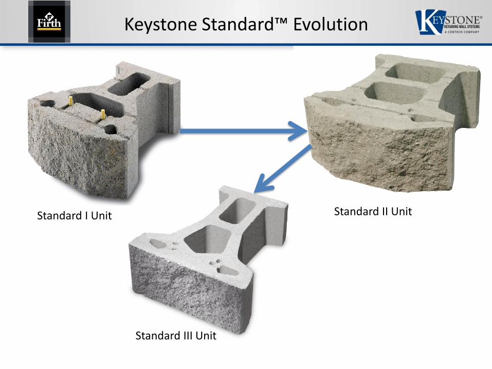
Keystone Standard™ Evolution
Standard II Unit
Standard III Unit
Standard I Unit

Standard I → III
• Wider pin receiving hole for more alignment flexibility
• Vertically aligned cores for ease of core filling
• Individual unit weight decrease of 4.5 to 5.5 kg
• Superior connection strength
• Greater construction flexibility

Gravity Applications

Gravity Applications
• Single Width Unit Maximum Heights (Good Soil Conditions)
– Battered (no surcharge) – 2 m
– Vertical (no surcharge) – 1.5 m
• Interlocked Back to Back Standard Units (Good Soil Conditions)
– Battered (no surcharge) – 2.8 m
– Vertical (no surcharge) – 2.2 m
• For most gravity application batter always recommended

Piece # 1 2
Height 200 200
Width 455 455
Depth 305 305
Weight (kg) 37 34
Pins Straight Pins -2/unit
Face Area 0.091 m2
Note: Unit colors, dimensions, weight, and availability vary by manufacturer.
Keystone
Compac IV
Straight Face Split Tri - Face Split1. 2.
Bottom View
Of Compac IV

Compac Unit
• Workhorse of Keystone – probably 75% of walls Nationally & Internationally are with Compac unit designs.
• When utilized with geogrid reinforcement, walls of all height can be designed.
• Highway Innovative Technology Evaluation Center (HITEC)
– U.S. DOT highway geogrid wall system evaluated for long term connection
• ICC-ES report ESR-2113, ICC-ES is a subsidiary of International Code Council.
– Evaluation service for independent verification of compliance to the International Building Code (IBC)

KeySystem II HITEC
• Evaluation published April 2012
• Evaluation based on AASHTO LRFD 5th
Edition, 2010 and NHI FHWA 2009
• Keystone Compac II Units
• Mirafi Geogrid

Keystone Compac™ Evolution
Compac II Unit
Compac III Unit Compac IV Unit

Compac I → IV
• Wider pin receiving hole for more alignment flexibility
• Vertically aligned cores for ease of core filling
• Individual unit weight decrease of 4.5 to 5.5 kg
• Superior connection strength
– 40% to 100% increase in geogrid connection
• Greater construction flexibility

Compac IV
• Universal Facing Unit
– One facing unit used to construct wall system
– Universal facing unit allows on-site alignment changes without delays of casting specialty panels
– Facing units are field cut for pipe penetrations or other obstructions
– Facing unit can be field cut for slip joints in excessive settlement conditions
– Face batter adjustable from 1H:8V to 1H:64V
– Various color and texture options available
Keystone Wall Advantages

MBW Connection and Alignment
• Keystone Fiberglass Pins
– Quick & easy alignment for stacking units
– Provides various degrees of setback
– Unit shear connector every 12”
– 20% better connection strength
– Allows geogrid to be pre-tensioned
– Ensures grid is attached to wall
– Non-corrosive
– High strength 6,400 psi short beam
12” O.C.

Components
• High Density Polyethylene (HDPE) Geogrids
– Behaves like plastic
– Uses lower % of ultimate due to creep
– Extruded and stretched structure
– High dimensional stability
– Newer versions have lower soil interaction values

Components
• Polyester (PET) Geogrids– High strength uniaxial polyester geogrid
– Woven and coated with a PVC coating
– Broad ultimate tensile strength range
– Excellent durability properties

Products – KeySteel
• KeySteel® Soil Reinforcement
200 mm (7.8 in.)
200 mm (7.8 in.)

Components – Face Unit
• Keysystem I Unit
– Compressive Strength• 4000 psi
– 82 kN Ultimate reinforcement connection strength @ 15 mm Displ.

0
5000
10000
15000
20000
25000
0 0.5 1 1.5 2 2.5
Co
nn
ec
tio
n C
ap
ac
ity
(lb
s)
Displacement (in)
KeySystem I Unit/KeyStrip Connection
18600 plf @ 0.5 in. displacement 19600 plf Ultimate Connection load
12000 plf @ 2” deformationMax Keystrip design load is 9000 lbs (FS conn >2)
KeyStrip™/Facing Connection

Components – Soil Reinforcing
• KeyStrips
– 9mm, 10mm, 11mm Wire
– Crossbars at 300mm & 450mm
– Hot Dipped Galvanized
– 75 to 100 year design life
– Connection capacity limited to 42.4 kN, after factors of safety applied

Components - Pins
• W24 – 14.3mm Steel Connection Pins (9/16” diameter)
• 12.7mm Fiberglass Alignment Pins

Wide Range of Applications
• Heavy Construction– Industrial walls
– Heavy Highway
– Railway Design
• Transportation– Bridge Abutment
– Development Roadways
• Seismic– Better Seismic Performance under heavy loads than
extensible geogrid

KeySteel
Waikato Expressway Construction

KeySteel

Design Methods and Seismic

Successful Walls
Require attention to four items.
Products
Soils
Construction
Design

Soil Summary
Soil Types
• Granular Soils - Sand & Gravels
• Fine Grained Soils - Silt & Clays
• Other - Organic, Peat
Preferred Soil GradationSieve Size % Passing
2 inch 100-75
3/4 inch 100-75
No. 40 0-60
No. 200 0-35
PI < 15 LL <40

Soil Summary
Design Properties
• γ, Moist Unit Weight
• φ, Effective Shear Strength
• c, Cohesive Strength
Minimum Compaction Density
• 95% of Standard Proctor
• 92% of Modified Proctor
• Moisture +0%, - 3%

SRW Design
The art of balancing driving and resisting forces.
External Stability• Base Sliding• Bearing Capacity
& Settlement• Overturning• Global Stability
Internal Stability• Reinforcement Tension• Pullout
Facing Stability• Connection• Shear/Bending• Overturning @ Top

Gravity Walls
Gravity walls rely on their mass
and batter to resist overturning.
Retained Soil ZoneWall Height
Keystone Units
Drainage Collection Pipe
Drainage Fill
Finished Grade/Backslope
Finished Grade
Leveling Pad
Limit of Excavation
Low Permeability Soil
Setback
Batter
Foundation Soil Zone

Gravity Wall Failure Mode
Gravity walls typically fall over
when built too tall for unit size
Earth Pressure
Weight of Wall
Overturning
Pivot
Earth
Pressure
Weight of Wall
Overturning
Pivot
Simple Overturning
Settlement and Overturning

Reinforced MSE Walls
The creation of a reinforced mass or
geocomposite, made of soil,
geosynthetics or steel reinforcement,
and concrete facing units,
of sufficient size to resist
the imposed forces.
Tileco Keystone Engineering Seminar

Reinforced Walls
Retained Soil Zone
Wall
Height
Keystone Units
Drainage Collection Pipe
Drainage Fill
Finished Grade/Backslope
Finished Grade
Leveling Pad
Limit of
Excavation
Low Permeability Soil
Setback
Batter
Foundation Soil Zone
Geosynthetic
Reinforcement
Reinforced Soil Zone
Reinforced walls rely heavily on
soil strength for the structure.

Design Guidelines

Design Methodology
• Rankine and Coulomb design using allowable stress design (ASD) and factor of safety (FS) methods.
𝑅
𝑃≥ 𝐹𝑆
R = Resistance (stabilizing forces)
P = Load (destabilizing forces)
• AASHTO Load Resistance Factor Design (LRFD) and Capacity Demand Ratio (CDR)
𝐶𝐷𝑅 =𝜑 𝑅
(𝛾1∗𝑃1)+(𝛾2∗𝑃2)> 1.0
𝜑 = resistance factor
R = resistance (stabilizing forces)
γ = load factor for a certain load type
P = Load of a certain type (destabilizing force)

Earth Pressure Theory
Coulomb (1776) Theory
H
Pa
R
W

Earth Pressure Theory
Rankine (1857) Theory
H
Pa
W
R

Earth Pressure Theory
Inextensible Theory
H
0.3H Coherent Grav. - Ko + OT
Simplified - 1.7 to 2.5Ka
Coherent Grav. - Ka + OT Simplified - 1.2Ka

K/Ka Ratio (Proposed)
*Unofficial DocumentCurrently in AASHTO sub-committee, awaiting review and approval.

Formulas – Earth Pressure
Pa = 1/2 g H2 Ka
Ka =Sin2 (+)
Sin2 Sin (-)Sin(+)Sin(-)
Sin(-)Sin(+)1 +
Coulomb
Rankine
Pa = 1/2 g H2 Ka
Ka = Cos()Cos() - Cos2()-Cos2()
Cos() + Cos2()-Cos2()
2

Failure Plane Location
For level surcharge and infinite slope conditions
• Coulomb - Coulomb failure plane varies as a function of the wall geometry and friction angles for both the soils and the soil wall interface.
tan 𝜌 − 𝜑 =− tan 𝜑 − 𝛽 + tan 𝜑 − 𝛽 tan 𝜑 − 𝛽 + cot 𝜑 + 𝑙 {1 + tan 𝛿 − 1 cot 𝜑 + 𝑙 ]
1 + tan 𝛿 − 𝑙 [tan 𝜑 − 𝛽 + cot 𝜑 − 𝑙 ]
where:𝜑 = angle of internal friction𝑙 = batter of wall measured from vertical (α - 90°)
β = slope angle above the wallδ = angle of friction at back of wall
• Rankine – Where 𝜌 is fixed and measured from horizontal under all design scenarios, which is only technically correct for level surcharge applications and minimal wall batter.
𝜌 = 45° +𝜑
2
• In theory, the Rankine failure plane varies under backslope conditions. However, it is customary to fix the failure plane at the equation above in earth reinforcement design, thus best representing the curved failure surface and locus of maximum stress points for a reinforced soil mas

Design Methodology Comparisons
• Major difference between Rankine and Coulomb– Coulomb model and equations account for friction between
the back of the wall and the soil mass as well as wall batter.
– Rankine equations more conservatively assume no wall friction at the soil-wall interface and a vertical wall structure which greatly simplifies the mathematics of the problem.
– The friction at the back of the wall face and at the back of the reinforced zone for external stability computations, provides an additional resisting force component that helps support the unstable wedge of soil.
– Because of the additional resisting forces, lateral earth pressure in Coulomb is generally less than Rankine method.

Design Methods
• The limitations of closed form solutions, such as Coulomb and Rankine, is that only simple level and infinite sloping surcharges with uniform loadings can be analyzed.
• It is necessary to look at a “trial wedge” or “approximation method” when attempting to analyze broken back slope or other slope/load combinations.

Design Methods
• AASHTO and NCMA suggest an approximation method for broken-back slope conditions that defines equivalent design slopes for the external analysis. – However, the internal analysis is not well defined for unusual
slopes and loading conditions and the designer is expected to use engineering judgement with the simplified methods.
• Keywall “Trial wedge” analysis used is consistent with the fundamental assumptions of the applicable coulomb and Rankine theories by setting δ=β. – “Trial wedge” results match the equation solutions for the level
and infinite slope conditions, but will determine the “correct” internal and external values for broken slope conditions and offset live and dead loads.
*Note AASHTO LRFD use the AASHTO “Simplified” method for calculating internal pressureand the trial wedge for calculating external loading conditions. MSEW utilizes Trial Wedge.

Design Methods
• Which method do I use?
– Each methodology is fundamentally different
– Understand the design methodology for a particular project
– Project Specific• Public / DOT – AASHTO / Rankine
• Schools – Coulomb
• Private – Rankine
– The most important issue is that the designer understand and be comfortable with a design methodology, its limitations and follow the methodology in its entirety.

Design Methods
Coulomb• Provides lowest calculated
earth pressure by taking all beneficial components into account– Wall Batter– Wall Friction
• Reinforcement lengths significantly longer at the top of wall than the bottom due to flatter failure plane
• Reduced earth pressure may permit vertical spacing of reinforcement in lower walls that exceed the wall facing’s stability during construction
Rankine
• No assumption has to be made with regard to friction between the wall structure and retained soil mass.
• Simpler formula and failure plane definitions
• Due to the higher earth pressure coefficient, stronger reinforcement may be necessary at the bottom of wall.
Advantages / Disadvantages

External Stability – Reinforced Wall Forces
NCMA/Coulomb does not include vertical forces (Allowed in 3rd Ed.)
Rankine/AASHTO does include vertical forces

External - Sliding Analysis

External - Sliding Analysis
Coulomb Rankine - AASHTO
• Driving Forces(Pa+Pq) cos β
• Resisting Forces
(Wf+W1+W2+Pav+Pqv) tan φweaker soil (reinforced or
foundation) as the resisting force
• Driving Forces(Pa+Pq) cos δ
• Resisting Forces
(Wf+W1+W2) tan φweaker soil (reinforced or
foundation) as the resisting force
*
*Rankine includes vertical earth load components. NCMA 3rd Editions now permits the inclusion of vertical earth load components at the designers option.
Note: Live load does not contribute to resisting forces.

External - Overturning Analysis

External - Overturning Analysis
Coulomb Rankine - AASHTO
• Driving Forces(Pa+Pq) cos β, are the driving forces at there respective moment arms of H/3 or HS/3 and H/2 or HS/2 up from the toe
• Resisting Forces
(Wf,W1,W2,Pav,Pqv) at their
respective moment arm from the toe to each center of gravity as the resisting moment
• Driving Moments(Pa+Pq) cos δ, are the driving forces at there respective moment arms of H/3 or HS/3 and H/2 or HS/2 up from the toe
• Resisting Forces
(Wf, W1, W2) at their respective
moment arm from the toe to each center of gravity as the resisting moment.
Note: Live load does not contribute to resisting forces. The live load surcharge is included as a driving force and not as a stabilizing force. Only permanent forces within the wall are included as stabilizing forces.

Reinforced Wall Analysis
Bearing Capacity Settlement
Bearing and Settlement
are geotechnical issues
Movement
Movement

External – Bearing Capacity / Settlement
• No calculation differences• Differences in the Factor of Safety
– F.S. > 2.0 NCMA– F.S. > 2.5 AASHTO ASD– CDR > 1.0 AASHTO LRFD (For Bearing be careful as a reduction
factor of 0.65 is applied, which under ASD would be a 2.0 factor of safety.)
• Settlement, particularly differential settlement should be evaluated by a qualified engineer.
• Maximum allowable differential settlement for reinforced soil systems– 1% NCMA– ½% FHWA

Internal Stability Analysis
Internal stability is the ability of the reinforced mass to maintain its structure and resist the applied loads without deforming or failing.
• In soil reinforced wall system, it is the tensile and pullout capacity of the reinforcing elements and inter-unit shear/connection capacity that holds the potential wedge of soil in place.
• The retained soil mass, or structure, is composed of the Keystone units at the face combined with reinforcing elements extending back beyond the Coulomb or Rankine failure plane.

Reinforced Wall Analysis
Internal Stability
Tension, Connection and Pullout
Connection Tension Pullout
Units Active Wedge Passive Zone

Reinforced Wall Analysis
Overturning
Bending Bulging
Shear
Local Stability
Overturning, Bending, Shear

Reinforced Wall Analysis
Geogrid Load = (σq + σa) • Tributary Area ≤ Tal
Earth pressure resisted by top reinforcement
Earth pressure resisted by 2nd reinforcement
Earth pressure resisted by 3rd reinforcement
Earth pressure resisted by 4th reinforcement
aqBase Shear

Pullout Force Analysis
Pullout = (2 Le)(γ Hov)(Tan φCi)
FS = Pullout / Geogrid Load
Pullout capacity of top reinforcement
Pullout capacity of 2nd reinforcement
Pullout capacity of 3rd reinforcement
Pullout capacity of 4th reinforcement
Le1
Le2
Le3
Le4
Hov

Internal Stability Analysis
There are no differences in the internal formulas between Coulomb and Rankine methods. The only difference is ASD vs. AASHTO LRFD and the application of load and resistance factors in the internal calculations.
The Elements of Internal Design are to ensure:1. The tensile elements do not exceed their working stress or factored
resistance limits.2. The tensile element have adequate connection capacity to the
Keystone units.3. The tensile elements have adequate anchorage beyond the potential
failure plane to hold the wedge of soil in place.4. There is not a potential surface where the mass can shear internally.5. The facing is stable against potential shear, bulging and overturning.

Design Comparison
• Design Scenario
– Wall Height 20’
– Retained and Found. soil zone parameters 28°, γ=19 kN/m3
– Reinforced Zone Foundation 32°, γ=19.6 kN/m3
– Infinite backslope 2h:1v, (26°)
– Level Toe Slope
– Near Vertical Wall batter
– Compac II, Mirafi Geogrids

Design Comparison - Rankine

Design Comparison - Coulomb

Design Comparison - Difference
Rankine Coulomb
Failure Plane

Design Comparison – Vertical Comp.

Design Comparison - Battered
Rankine Coulomb

Design Comparison – Vertical Comp.

MSE Wall Design and Seismic

Seed & Whitman (1970) Quotes
"While all investigators have concluded that the dynamic lateral pressures developed during earthquakes exceed the static pressures on earth retaining structures, a survey of a number of engineering companies highway departments and port authorities in California shows that .... it is general practice to make no special allowance for increased lateral pressures on retaining walls .... due to earthquake effects. This also appears to be the case in many other countries."

Seed & Whitman (1970) Quotes
"It should be noted that the factor of safety provided in the design of walls for static pressures may be adequate to prevent damage or detrimental movements during many earthquakes. (...) Thus where backfill and foundation soils remain stable, it is only in areas where very strong ground motions might be expected, for walls with sloping backfills or heavy surcharge pressures and for structures which are very sensitive to wall movements, that special seismic design provisions for lateral pressure effects may be necessary."

Classical Earth Pressure Theory
• Coulomb
• Rankine
• Mononobe-Okabe

Formulas – Earth Pressure
Pa = 1/2 g H2 Ka
Ka =Sin2 (+)
Sin2 Sin (-)Sin(+)Sin(-)
Sin(-)Sin(+)1 +
Coulomb
Rankine
Pa = 1/2 g H2 Ka
Ka = Cos()Cos() - Cos2()-Cos2()
Cos() + Cos2()-Cos2()
2
Note: Backslope can not be greater than phi angle

Mononobe-Okabe (1929)

Mononobe-Okabe (1929)
• Backslope MUST be < φ of retained zone
• Let’s look at the critical portion of the equation
sin(𝜑 − 𝜃 − 𝑖)
𝜑 = angle of friction of soil
𝜃 = 𝑎𝑟𝑐 tan(𝐾ℎ
1−𝐾𝑣)
𝑖 = backfill slope angle.

Mononobe-Okabe (1929)
• Example
𝜑 = angle of friction of soil = 28°
𝜃 = 𝑎𝑟𝑐 tan(𝐾ℎ
1−𝐾𝑣) where, Kh=0.20g, Kv=0
𝜃 = 11.3°
𝑖 = backfill slope angle = 3h:1v = 18°
sin(28 − 11.3 − 18) = sin (-1.3) = -0.023 / Neg. Value
Mononobe Equation doesn’t solve

Mononobe-Okabe (1929)
• How are we working around this?
• When sin(𝜑 − 𝜃 − 𝑖) is negative this portion of the equation is often set to 0
• Other forms of analysis is important
– Slope stability programs using cohesion
– Finite element analysis
– Displacement Method?
• The problem is that we are trying to solve something that we don’t completely understand or are attempting to put 2-D numbers to a 3-D solutions.

Coulomb vs. Rankine Question
How do we use M-O -Coulomb seismic
analysis if Rankine earth pressure is the
prevailing theory for MSE wall design?
Coulomb = Rankine if delta angle is set
equal to backslope angle and batter is set
equal to zero.
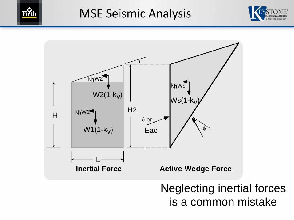
MSE Seismic Analysis
H
W1(1-kv)
khW1
W2(1-kv)
L
or
Eae
Inertial Force Active Wedge Force
H2
Ws(1-kv)
khWs
khW2
Neglecting inertial forces
is a common mistake

MSE Seismic Analysis Application
Kdynamic = Kae - Ka
H2 = H +Tan x 0.5H
(1 - 0.5 Tan)
H
L
khWEstatic
H'
d
EvEh
khW1
Re
EvEh
cL
H2
.5H2
Effective
zone
W1
khW
or
Edynamic
0.6H2HÕ/3
@ 50%

Seismic MSE Internal Analysis
Pi = Am (W1 + W2 + W3)
Add'l Load/reinf = (Pi)Le of reinforcement level
Sum of Le for all reinforcement levels
H
B
W3HÕ/2
d
W2AmW1
AmW2
AmW3
LeW1
0.3H
HÕ/2
H
B
W3
H'
d
W2AmW1
AmW2
AmW3
45+/2
LeW1
Extensible Reinforcement Inextensible Reinforcement

Displacement Analysis
The Mononobe-Okabe equation for earth
pressure is still used widely for design,
although actual conditions during
earthquake shaking of retaining structures
are quite different from those assumed in
developing the equation…
The proposals of Richards and Elms have
simulated use of design methods based
upon allowable permanent displacement.
Robert V Whitman (1990)

Displacement Analysis
Displacement Controlled Design
Richards and Elms (1979/1990)

Displacement Analysis

Displacement Analysis
Maximum Acceleration, Kh
Richards and Elms
N = A 0.087 V2 1/4
d A g[ ]Where:
N = Design Cutoff Acceleration
A = Peak Design Acceleration
V = Peak Velocity
d = Allowable Displacement
g = Gravitational Acceleration

Displacement Analysis
Simplified Acceleration, Kh
Kavazanjian et al.
kh = 0.74 As As 1/4
d[ ]Where:
kh = Horiz Acceleration Coeff.
As = Design Acceleration
d = Allowable Displacement (in)
(1” - 8” range)

Displacement Analysis Summary
“For most design purposes, it has been shown (Elms and Martin, 1979) that a design value of Kh = 0.50A is adequate, provided that the wall can accommodate an outward displacement of up to about 250A mm”(10A in inches).
Geotechnical Earthquake Engineering by the
Federal Highway Administration (1998)

What PGA, A, or kH to use?
What is the design earthquake?
• 2% probability in 50 years
• 10% probability in 50 years
• 40% probability in 50 years
• 7% probability in 75 years
• All or some of the above
This is an Owner driven criteria based on the importance of the structure.

New Zealand PGA Determination
• NZ Transportation Agency’s Bridge Manual
– 6.0 Site stability, foundations, earthworks and retaining walls• Loads determined from section 6.2.2
• Other NZ design references for MSE walls
– Road Research Unit Bulletin 84• Provides a basis for seismic design
• Shall be compiled with
– NZTA research report 239• Provides additional guidelines

NZ Bridge Manual Section 6.2.2

NZ Bridge Manual Section 6.2.2

Addendum 6A Table 6A.1

NZ Seismic Maps

NZ Bridge Manual Section 6.6
• 6.6 Earth Retaining Systems
– Numerous codes can provide guidance

NZ Bridge Manual Section 6.6
• 6.6.9 Design performance of earth retaining structures and slopes
– “Retaining structures and slopes may be designed to remain elastic under the design earthquake load specified in 6.2.2 or to allow limited controlled permanent outward displacement under strong earthquake shaking.”
– “The displacement likely at the design ultimate limit state seismic response, and under the MCE (maximum considered event), shall be assessed using moderately conservative soil strengths consistent with the anticipated strain and Newmark Sliding Block displacement approach.”

Section 6.6.9

Current US Highway Seismic Criteria
Retaining walls around bridges have been designed for a 2% exceedance in 50 year event.
Retaining walls away from bridges have been designed for a 7% exceedance in 75 year event.
Note: The PGA of a 7% probability event is around half of a 2% probability event.

Is Seismic Analysis Necessary for MSE Walls?
11.5.4.2 AASHTO – Extreme Event I, No Analysis
“A seismic design shall not be considered mandatory for walls located in Seismic Zones 1 through 3, or for walls at sites where the site adjusted peak ground acceleration, As, is less than or equal to 0.4g, unless one or more of the following is true:”
*AASHTO LRFD Bridge Design Specifications, 7th Edition, 2014, 2015 Interims.

Is Seismic Analysis Necessary for MSE walls?
Cont’d
• Liquefaction induced lateral spreading or slope failure, or seismically induced slope failure, due to the presence of sensitive clays that lose strength during the seismic shaking, may impact the stability of the wall for the design earthquake.
• The wall supports another structure that is required based on the applicable design code or specification for the supported structure to be designed for seismic loading and poor seismic performance of the wall could impact the seismic performance of that structure.
*AASHTO LRFD Bridge Design Specifications, 7th Edition, 2014, 2015 Interims.

Is Seismic Analysis Necessary for MSE Walls?
Cont’d
• In Seismic Zones 2 and 3
– Exposed wall height plus average surcharge depth is > 30’
– Tiered walls the sum of the exposed height of all the tiers plus the average soil surcharge depth is > 30’
– The wall has abrupt changes in its alignment geometry (e.g., corners and short radius turns at an enclosed angle of 120 degrees or less)
– For gravity and semi-gravity walls, the wall backfill does not meet the requirements of Article 7.3.6.3 of AASHTO.
*AASHTO LRFD Bridge Design Specifications, 7th Edition, 2014, 2015 Interims.

Why the change?
Observed Seismic Performance for Walls
• Good performance of MSE Walls in Seismic Events– 1995 Kobe Earthquake; masonry and concrete gravity walls
collapsed due to weak soils, heavy soil surcharges, or structural failure, mainly where As>0.6g; MSE Walls had some damage but did not collapse even up to 0.8g
– 1999 Izmit Earthquake (As>0.40g); Rigid Structure Collapse MSE Structures remained in place
– 2001 San Salvador Earthquake (As>0.30g); Example wall shown

1995 Kobe Earthquake Japan
Tatsuoka et al.GRS Wall - 1992 Before

1995 Kobe Earthquake Japan
Tatsuoka et al.GRS Wall - 1995 After

1995 Kobe Earthquake Japan
Tatsuoka et al.GRS Wall - After RCW Wall - After

1999 Izmit Turkey Earthquake
Mark Aschheim et al.

1999 Izmit Turkey Earthquake
Mark Aschheim et al.

1999 Izmit Turkey Earthquake
Mark Aschheim et al.

Why the change?
Laboratory Seismic Studies
• Two seismic forces are out of phase– Dynamic earth pressure was at its maximum, the wall inertial force was
at its minimum or very close to 0
– When the wall inertial force was at its maximum, the total seismic earth (Pae) was close to its static value.
• Nakamura, S. (2006). “Re-examination of Mononobe-Okabe theory of gravity retaining walls using centrifuge model tests.” Soils Foundation 46(2), 135-146
• Al Atik, L., and Sitar, N. (2010). “Seismic earth pressures on cantilever retaining structures.” Journal of Geotechnical and Geoenvironmental Engineering, 136(10), 1324-1333
• Seismic earth pressures appear to not develop until As>0.4g• Al Atik, L., and Sitar, N. (2010). “Seismic earth pressures on cantilever retaining
structures.” Journal of Geotechnical and Geoenvironmental Engineering, 136(10), 1324-1333

Why the change?
Seismic Earth Pressures on Cantilever Retaining Structures
Linda Al Atik and Nicholas Sitar, 2010
Abstract in the Journal of Geotechnical and Geoenvironmental Engineering – ASCE
Laboratory Centrifuge Experiments

Al Atik and Sitar (2010)
*Al Atik and Sitar (2010)

Why the change?
*Al Atik and Sitar (2010)

Al Atik and Sitar (2010)
Seismic Behavior of Wall –Backfill System
• Comparison of dynamic moment increments, dynamic earth pressure increments and wall inertial forces.
Dynamic Earth Pressure near maximum
Wall mass inertial force near zero or negative

Al Atik and Sitar (2010)
Observations and Interpretations
“…when the inertial force acts in the active direction, the total earth pressure is equal to or less than the static earth pressure. Dynamic earth pressure increment is at its maximum when the inertial force is close to zero (i.e. static case) or when the inertial force acts the passive direction.”

Al Atik and Sitar (2010)
Observations and Interpretations
“In contrast, the limit equilibrium assumption inherent in MO theory means that the earth pressure increases when the inertia force is loaded in the active direction and stability analyses of retaining are usually conducted for maximum dynamic earth pressures and inertia forces.”

Al Atik and Sitar (2010)
Shows earth pressure distribution is triangular, indicating resultant at h/3 and less than 65% of M-O earth pressure.

Conclusions
1. The experimental and numerical analysis results consistently show that the maximum dynamic earth pressures increase with depth and can be reasonably approximated by triangular distribution analogous to that used to represent static earth pressures. Consequently, there seems to be no basis for the currently accepted position of the point of application the dynamic earth pressure force in dynamic limit equilibrium analyses at 0.6 to 0.67 H and, instead, the point of application should be at 1/3H, as originally suggested by Mononobe and Matsuo (1932).
*Al Atik and Sitar (2010)

Conclusions
2. An important aspect of the dynamic interaction between the cantilever retaining walls and retained soils is the fact that the maximum dynamic earth pressures and maximum wall inertial forces to not tend to occur simultaneously. As a result, the current design methods based on the MO theory were found to significantly overestimate the recorded dynamic earth pressures and moments.
*Al Atik and Sitar (2010)

Conclusions
3. The relationship between the back-calculated seismic earth pressure increment coefficient (∆Kae) at the time of maximum dynamic wall moment and peak ground acceleration obtained from our experiments suggests that seismic earth pressures on cantilever retaining walls can be neglected at accelerations below 0.40g.
*Al Atik and Sitar (2010)

Conclusions
4. The analytical results show that the FE analysis is able to capture quite well the essential system responses observed in centrifuge experiments. However, the veracity of the numerical analyses is strongly dependent on access to high quality experimental or field performance data for model calibration and, therefore, field performance predictions using numerical models should be approached with caution.
*Al Atik and Sitar (2010)
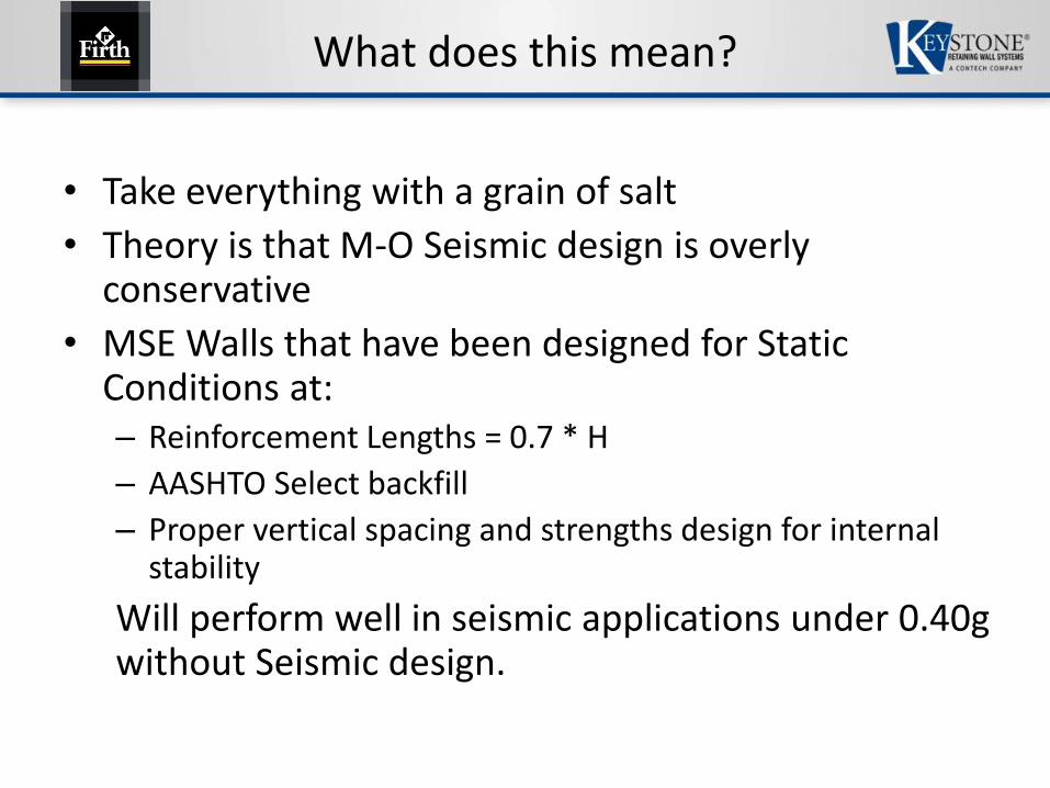
What does this mean?
• Take everything with a grain of salt
• Theory is that M-O Seismic design is overly conservative
• MSE Walls that have been designed for Static Conditions at:– Reinforcement Lengths = 0.7 * H
– AASHTO Select backfill
– Proper vertical spacing and strengths design for internal stability
Will perform well in seismic applications under 0.40g without Seismic design.

What does this mean?
• Does this mean that seismic design can / should be eliminated below 0.40g?– Use your judgement– Slopes are still a big issue, especially high backslope low friction angle soils– Likely 20 states or so have A > 0.40g– Most seismic states will require a design even if it is below 0.40g.
Kho = Fpga x PGA = As, For PGA > 0.50g -> Fpga = 1.0, site class B, C, DKh = 0.5 x Kho (or As)
• The below 0.40g criteria was broadcast generally to all wall types including gravity and semi-gravity.– The idea that segmental gravity walls including large gravity block walls (no
geosynthetic reinforcement) can withstand seismic below 0.40g without toppling over seems aggressive. Especially considering the large rigid structures failing in seismic conditions.
• Review counter points– Leshchinsky, D., and Vahedifard, F., and Shahrokhabadi, S., “Does No-seismic
Design in AASHTO violate AASHTO’s rules?” 2015 Geosynthetics Conference, February 15-18, Portland, OR

What does this mean?
*Leshchinsky et. al., (2015)

Keystone Resources
• Design Software
– KeyWall®
– Excel spreadsheets
• Technical Notes
• Standard Drawing Details
• Design Manual
• Construction Manual
• Specifications

Speaker Profile
Dan Tix, P.E.
Engineered Structures Technical ManagerKeystone Retaining Wall Systems, LLC
Dan has been working in the segmental retaining wall industry for 12 years. Dan has over 9 years of MSE Wall design experience working in Keystone’s engineering department. His current position is Engineered Structures Technical Manager, where he coordinates and manages Keystone’s DOT product submittals, is responsible for managing structural wall product offerings nationwide and teams with Keystone’s region managers and international partners to provide technical / engineering support for project sales and promotion. Prior to working for Keystone, he worked 2 years as a geotechnical consulting engineer in Michigan. Dan graduated from Michigan Technological University with a B.S. in Civil Engineering in 2001. He is a licensed Professional Engineer in the state of Minnesota since 2007.