45306-001: takhiatash power plant efficiency · pdf file21582i00050 version 5 20/01/2014...
TRANSCRIPT

21582I00050 Version 5 20/01/2014
TECHNICAL DUE DILIGENCE REPORT
UZB: Takhiatash Power Plant Efficiency Improvement Project Note: Prepared by the Consultant for the Asian Development Bank.

21582I00050 Version 5
Version 5 20/01/2014
20/01/201
TECHNICAL DUE DILIGENCE
REPORT
TAKHIATASH THERMAL POWER PLANT PROJECT PREPARATORY CONSULTANCY SERVICES
/2014
TECHNICAL DUE DILIGENCE
REPORT
TAKHIATASH THERMAL POWER PLANT PROJECT PREPARATORY CONSULTANCY SERVICES

21582I00050 Version 5 20/01/2014 pag. i
Technical Due Diligence Report
Index
1. Introduction ................................................................................................................................ 1
2. Objective .................................................................................................................................... 2
3. Scope .......................................................................................................................................... 3
4. Description of the Project ......................................................................................................... 3
5. Review of Technical Information, field survey and assessment .......................................... 4
5.1. Process and Mechanical ...................................................................................................... 4
5.2. Electrical ............................................................................................................................. 23
5.3. Control and Instrumentation ............................................................................................... 25
5.4. Civil .................................................................................................................................... 28
5.5. Project Implementation ...................................................................................................... 30
5.6. General Lay-out ................................................................................................................. 32
6. Technical Specifications ........................................................................................................ 33
7. Project outcome ...................................................................................................................... 33
8. Conclusions and Recommendations .................................................................................... 34
8.1. Power Demand .................................................................................................................. 34
8.2. Gas Supply......................................................................................................................... 34
8.3. Power evacuation .............................................................................................................. 35
8.4. CCGT Configuration .......................................................................................................... 35
8.5. CCGT Capacity .................................................................................................................. 35
8.6. Steam Turbine By-pass ..................................................................................................... 35
8.7. Gas By-pass capability ...................................................................................................... 36
8.8. Heat sink and water source ............................................................................................... 36
8.9. Climatic conditions ............................................................................................................. 36

21582I00050 Version 5 20/01/2014 pag. ii
8.10. Cooling System .................................................................................................................. 36
8.11. Water Treatment ................................................................................................................ 37
8.12. Heating system .................................................................................................................. 38
8.13. CCGTs construction schedule ........................................................................................... 38
APPENDIX I: GAS SUPPLY CONTRACT ANALYSIS ................................................................ 0
APPENDIX II: DECOMMISSIONING PLAN ................................................................................ 0
APPENDIX III: DETAILED COST ESTIMATES .......................................................................... 0
APPENDIX IV: IMPLEMENTATION SCHEDULE ....................................................................... 0
APPENDIX V: GENERAL LAY-OUT ............................................................................................ 0

21582I00050 Version 5 20/01/2014 pag. iii
Glossary of Acronyms
ADB Asian Development Bank
BOD5 Biological Oxygen Demand over 5-day period
CAPS Central Asian Power Supply
CCGT Combined Cycle Gas Turbine
CDS AFPA Centralized Digital System Of Automated Frequency And Active Power Adjustment
COC Cycles Of Concentration
COD Chemical Oxygen Demand
CWT Chemical Water Treatment
DCS Distributed Control System
DH District Heating
EPC Engineering, Procurement And Construction
GDS Gas Distribution Station
GHG Greenhouse Gas
GNFE Gas Natural Fenosa Engineering
GPD Graphical Parameters Display
GT Gas Turbine
HRSG Heat Recovery Steam Generator
ISO International Organization For Standardization
LCD Local Dispatch Center
LHV Lower Heating Value
LTSA Long Term Service Agreement
LV Low Voltage
MCR Main Control Room
MV Medium Voltage
NLDC National Load Dispatch Centre
NOx Nitrogen Oxides (NO And NO2)
PCB Polychlorinated Biphenyls
PFS Prefeasibility Study

21582I00050 Version 5 20/01/2014 pag. iv
RH Relative Humidity
STM Server Of Telemetry
TDS Total Dissolved Solids
TIDS Tele-Information Display System
TPP Thermal Power Plant
TSS Total Suspended Solids
UDC Unified Dispatch Centre
UE Uzbekenergo
WTP Water Treatment Plant

21582I00050 Version 5 20/01/2014 pag. 1
1. Introduction
1. Uzbekistan’s power generation plants are generally old and inefficient, requiring urgent modernization. According to ADB’s Concept Paper (August 2012), more than 75% of the power plant units are over 30 years old reaching or exceeding their economic life. The thermal efficiency averages 31%, while that of energy efficient combined cycle gas turbine (CCGT) exceeds 50%. Replacing the existing power generation assets with energy efficient equipment is a key strategy for saving energy, securing reliable power supply, and reducing greenhouse gas (GHG) emissions.
2. The Takhiatash Thermal Power Plant is a multi-block conventional thermal power plant currently made up of four power blocks numbers III, IV, V and VI. Old blocks I and II were already dismantled.
3. The existing power blocks are conventional Rankine cycle units burning natural gas in boilers as main fuel and residual heavy fuel oil (mazut) as backup fuel.
4. The oldest block was commissioned in 1969 (Block III) and the newest in 1990 (Block VI). Blocks III and IV have an operating life in excess of 40 years, being usually considered for this type of units a design lifetime of 30 years. The efficiency of these old units is below 25%, being in the current power plants of the same technology close to 40% and in the combined cycle power plants using the same type of fuel above 55%.
5. Availability of the oldest units of blocks III and IV is not guaranteed in the long term and could be a serious safety problem in the midterm. So, in the current demand scenario, it is necessary to promote the substitution of these old generating facilities by new modern and more efficient ones.
6. The current price of the natural gas used for power generation in Uzbekistan is low compared with its price in international markets. It is more likely that in the midterm, the price would increase tending to approach to international prices. For this reason, the urgency for replacing inefficient and obsolete power generation units will be more as time goes by.
7. The objective of the project is to improve energy efficiency of the Takhiatash thermal power plant (TPP) with the adoption of energy efficient technology that will contribute to increased reliable power supply and climate change mitigation. The project will include construction of a 255 MW (nominal size) combined cycle gas turbine (CCGT) power plant, decommissioning of inefficient existing power plant units, and capacity development. This improve in energy efficiency will decrease the amount of gas consumed per MWe generated.
8. The project is a priority project identified by State Joint-Stock utility company Uzbekenergo (UE). The 730 MW Takhiatash TPP is the main power supply source for the Karakalpakstan and Khorezm regions with over 3 million people located in the western part of Uzbekistan. The power demand outlook is strong with a number of industrial development projects envisaged for the region, exceeding currently available capacity.

21582I00050 Version 5 20/01/2014 pag. 2
9. The current power generation and transmission infrastructures development plant in the area consists of three phases:
Phase 1: Construction of a first CCGT
Phase 2: Construction of a second CCGT
Phase 3: Construction of two 220 kV and one 500 kV transmission lines.
10. Phase 1 and Phase 2 consist of design, supply and installation of two 255 MW (nominal size) CCGT and decommissioning of existing blocks III and IV. CCGT units will comprise as a reference (i) gas turbine with electrical generator, (ii) heat recovery steam generator, (iii) steam turbine with electrical generator, (iv) steam condenser and (v) ancillary equipment including generator transformers, systems for control, electrical switching, water and gas treatment, cooling water, and all other plant auxiliaries. Construction will be done by a turnkey contractor. The contract scope will cover detailed design, selection of equipment, installation and commissioning.
11. The Asian Development Bank (ADB) issued on October 16th, 2012 the Terms Of Reference documentation for the consultancy services required for the preparation of a project of performance improvement of the Takhiatash Thermal Power Plant in Uzbekistan.
12. Gas Natural Fenosa Engineering (hereinafter GNFE) with the help of the local subcontractor IKS (jointly the Project Team or the Consultant), submitted a proposal for the above mentioned tender process, being finally awarded the contract for the consultancy services. The Consultant received the Notice to Proceed on January 8th.
13. In the Terms Of Reference documentation it was described the project considering the construction of a single combined cycle gas turbine unit of 280 MW capacity. During the Interim Mission carried out in April and May 2013 it was announced the change to consider two CCGT units of the same capacity and the structure of the project made up of three phases as described before.
2. Objective
14. The objective of the present report is to compile the results of the studies on the different components of the Project from the available technical information and the observations during the missions carried out between January and May 2013 by the Consultant. Technical specifications prescribed for the projected facilities are also included.
15. The present report also contains reached conclusions and makes recommendations for the easy development of the project and good future performance of the projected facilities.

21582I00050 Version 5 20/01/2014 pag. 3
3. Scope
16. The present report contains the information elaborated on the following main parts of the scope of the project:
Demolition of remaining structures of dismantled blocks I and II
Decommissioning of blocks III and IV
Construction of two new combined cycle units
4. Description of the Project
17. The Takhiatash Thermal Power Plant (Takhiatash TPP) is a power generation complex in operation, with a total installed capacity of 730 MWe. 18. It is the only power station located in the lower Amudarya River, generating and supplying the energy to the consumers of Nukus, the capital of the Republic of Karakalpakstan and to the Takhiatash city.
19. The TPP supplies energy also to the National Grid through two 220 kV transmission lines up to the Horezm power node and through a single 220 kV transmission line from the Horezm power node to the Navoi power node. The capacity of this link is limited to 140 – 160 MW. Due to this limitation the excess production can hardly be exported and the Takhiatash TPP must accommodate its production to the highly variable local demand.
20. Takhiatash TPP is located in Takhiatash city, in Khodjeyliy region of the Republic of Karakalpakstan (3 km to the South-West of the city centre).
21. The Power Plant is made up of the following components:
Blocks I & II (Already dismantled). Turbogroups foundation structures and buildings still exist. A still operating water heating system is located inside the turbine hall.
Blocks III & IV conventional Rankine cycle power units (6 boilers feeding a common header and 3 steam turbines (2x100 MW Block III+ 1x110 MWe Block IV) (Total 310 MWe).
Blocks V & VI conventional Rankine cycle power units (2x210 MWe).
Ancillary systems of operating blocks
Common auxiliary systems
22. The Takhiatash TPP efficiency improvement project consist of the following main components:
Construction of two combine cycle power units initially defined as 230 – 250 MW capacity each.
Construction of a new water heating station supplied by the new CCGT units
Demolition of existing structures of blocks I and II
Complete decommissioning of existing blocks III and IV

21582I00050 Version 5 20/01/2014 pag. 4
23. The project shall be implemented in a coordinated manner providing reliable continued supply of the electricity and heat demands.
5. Review of Technical Information, field survey and assessment
24. The major part of available technical information is contained in the following documents:
PREFEASIBILITY STUDY (PFS) elaborated by the“TEPLOELECTROPROJECT” Company, and
« POWER DISTRIBUTION SCHEME OF 140-160 MW GTU AND 70-90 MW STEAM TURBINE WITHIN IMPLEMENTATION OF 230-250 MW CCGT AT THE TAKHIATASH TPP» elaborated by the “SREDAZENERGOSETPROEKT” Company.
25. Additional information was obtained in the investigation made during the visits to the TPP carried out by the Consultant Process and Mechanical.
5.1. Process and Mechanical
Gas Supply
26. Two gas pipelines of 1120 mm diameter come from the Bukhara region from a compression station situated close to the Gazli gas fields. Two (2) 1020 mm diameter derive from the main pipelines and finally a 6,5 km long 720 mm diameter pipeline reaches the Gas Distribution Station (GDS) located 2 km away from the TPP. The total route of piping from the compression station to the GDS is about 500 km long.
27. The gas pressure in the origin ranges 35/40 kg/cm
2. Pressure in the GDS ranges
9/20 kg/cm2. Minimum supply pressure is 9 kg/cm
2 in winter. The temperature of gas is
close to ground temperature and it is highly variable depending on the ambient air temperature.
28. The water content in the gas is variable depending on the origin of gas. Mechanical separation of water will be installed in the GDS by Uztransgas before metering. High water content in the gas has been a source of conflicts in the past.
29. For the supply to the TPP in the GDS there are filters, condensate tanks, regulators, diaphragm type flow meter and a flow computer.
30. Quality of gas is in accordance with the Russian standard GOST 5542-87. This standard that is applicable to the export of gas to Russia, establishes limit values for different components of gas and for calorific value. Calorific value is 8.000 ± 100 kcal/m
3.
31. For the new plant, it is considered the construction of a new dedicated pipeline coming to the plant from the GDS currently supplying the operating blocks.

21582I00050 Version 5 20/01/2014 pag. 5
32. Natural gas is currently being supplied at a constant pressure of about 6 kg/cm2
at the terminal point (GDS, after the regulators). 33. Two separate pipelines supply natural gas to the existing units. A 530 mm diameter pipeline supplies gas to the blocks III and IV and a 325 mm diameter pipeline to blocks V and VI. Natural gas is conditioned separately for both groups of blocks in facilities equipped with mechanical scrubbing and liquid separation devices, pressure regulators and diaphragm type flow meters. A gas sampling tube goes to a laboratory where the Lower Heating Value (LHV) is measured by mean of a calorimeter and the composition determined by mean of a colorimeter.
34. The pressure required for the utilization in heavy duty gas turbines of the size fitting the present Project is above 20 kg/cm
2 (abs) depending on the gas turbine model.
It will be specified by the supplier of the finally selected gas turbine during the implementation.
35. In order to optimize the system, it is recommendable to request a guarantee of supply at the highest possible pressure, taking into account the above requirement. Connection of the new pipeline at a higher pressure is possible, however, in winter the pressure at this point drops to 9 kg/cm
2 due to the fact that the closest upstream
compression station is located more than 500 km far, so, in any case it is necessary to consider the installation of gas compressors in the power plant.
36. It is recommendable to install two compressors 100% capacity each common for phases 1 and 2.
37. The new 2 km long gas pipeline to be installed, for a minimum operating pressure of 9 kg/cm
2, would have a minimum diameter of 300 mm for a total capacity for
phases 1 and 2 of about 11 kg/s.
38. The current and forecasted contractual relationship between the gas supplier Uztransgas and the Power Plant have been analyzed. The conclusions of the analysis and recommendations are compiled in the report included in the Appendix I.
39. Taking into account that both gas buyer and seller are State Owned companies and that energy generation in the Takhiatash TPP and its distribution are made by Uzbekenergo without the need for a long term power purchase agreement, it is not considered necessary the existence of a gas supply long term contract. It is recommended, however, to consider this possibility and the improvement of some aspects of the current contract such as the invoicing based on units of energy (for example USD/MMBTU) (see Appendix I).
Characteristics of the new CCGT units
40. CCGT combined cycle technology consists of the combination of two thermodynamic cycles, the Brayton cycle and the Rankine cycle. The first produces electricity by mean of a gas turbine generator and the second by mean of a steam turbine generator. Hot exhaust from the gas turbine creates steam in a Heat Recovery Steam Generator (HRSG) that is fed into a conventional steam turbine, producing a second source of power. With the latest turbine technologies, natural gas combined cycle power plants can operate at an efficiency above 50%, which reduces emissions per electricity output respect simple cycle gas turbine plants and conventional steam technology.

21582I00050 Version 5 20/01/2014 pag. 6
CCGT Configuration
41. In the selection of the configuration of the new CCGT units, the current configuration of the blocks III and IV being substituted has to be taken into account. They have a six (6) boilers to three (3) steam turbine generators configuration very reliable and flexible for maintenance purposes.
42. Combined-cycle units are typically built in configurations abbreviated as 1+1, 2+1, 3+1, 3+2, or 4+1. The 2+1 configuration, for example, includes two gas turbines (GTs), each followed by a single heat recovery steam generator (HRSG), with the two HRSGs supplying one steam turbine generator set.
43. For a single unit of about 250 MW a number of different configurations are available. From the simplest 1+1 single shaft configuration in which one electrical generator is coupled to the gas and steam turbine to a combined configuration with several gas turbine generators and a steam turbine generator (2+1, 3+1, etc..).
44. The configuration considered for the present project is type 1+1 multishaft. The gas turbine and the steam turbine with its own generator each are mounted in separate shafts.
45. Both single shaft and multishaft configurations perform their specific functions, but the single shaft configuration excels in the base load and mid-range power generation applications.
46. Not all suppliers of gas and steam turbines of the size suitable for this project have available a single shaft configuration.
47. The multi-shaft combined-cycle system configuration is most frequently applied in phased installations in which the gas turbines are installed and operated prior to the steam cycle installation and where it is desired to operate the gas turbines independent of the steam system. In the present project the implementation of each combined cycle unit is planned in a single phase, however, separate supply of electricity from each of the two generators of the first unit at 110 kV and 220 kV, corresponding to the regional or national grid is considered.
48. The configuration considered for the new combined cycle units is type 1+1 multishaft. This configuration is appropriate for the new planned CCGT units 1 and 2. It will allow for units maintenance operations, as the existing blocks V and VI (2 x 210 MW) will be available as back-up.
CCGT Capacity
49. Although the capacity considered for each of the CCGT units in the PFS is 230 – 250 MW, it is recommendable to expand the range to about 280 MW in order to alternatively consider more gas turbine models that otherwise could not suit the expected range. The proposed definition of unit capacity is 255 MW ± 10% at ISO conditions.

21582I00050 Version 5 20/01/2014 pag. 7
Heating System
50. The new CCGT units shall provide heat for water heating (district heating, DH).
51. A medium pressure steam header shall be installed. Pressure in the header shall be kept constant.
52. Each CCGT will be able to supply the total amount of steam needed for the water heating station in the most demanding condition, alternatively from steam turbine extractions in normal operation or from the HRSG when the CCGT is running in ST by-pass mode.
53. The Project shall include a new common water heating system made up of two 100% steam condensers/heaters, pumps, piping, valves, auxiliary components, instrumentation and control and electrical supply as required. Storage tanks shall also be provided as required for a continuous and reliable operation of the system.
54. Since the heat supply will vary depending on the ambient temperature, it has been considered the following heat supply consumptions per period, according to the PFS:
Winter Period: 109,8 Gkcal
Summer Period: 29,2 Gkcal
55. The condensate formed from the steam used for heating the DH water returns to the cycle after purification if required.
Power Demand
56. The Power Plant currently supplies electricity to the National Grid and to a regional grid. According to the local dispatch, the maximum power being demanded to the Takhiatash Power Plant is around 550 MW. The maximum power supplied to the National Grid is 180 MW with a margin of 12%, resulting in an actual maximum of 150 MW. Maximum demand of the regional grid is 480 MW day time and 280 MW nights time. The availability of the existing blocks is low and so is the quality of the service being provided to the demand.
Fuel Composition
57. A periodic report on fuel composition is being provided by the distribution company. It appears that control of amount and quality of fuel being currently supplied to the power plant should be improved in order to be in accordance with international standards. For reference purposes, a continuous measurement of flow rate, fuel composition and possibly of other contractually guaranteed parameters should be carried out (see Appendix I).
58. Fuel composition: It is shown in the PFS as molar %. It may be assumed as the design composition.

21582I00050 Version 5 20/01/2014 pag. 8
59. Specific components and characteristics of the natural gas such as the Wobbe Index, the sulphur content and others should be within the limits that the gas turbine manufacturer will request in its Fuel Specification. Usually the supplier conditions their guarantees to the fulfillment of the limits of that Specification.
Demolition of old structures and decommissioning of old operating blocks
60. Old blocks I and II were dismantled in 1980. Foundations of steam turbo generators and buildings are still there. Buildings are used as occasional workshop and warehouse facilities.
61. A water heating facility and related equipment located inside the turbine building are still operating.
62. There are several mechanical interfaces to be solved in the buildings before they are ready for its complete demolition and removal, mainly electrical and control cables and some water and steam piping as shown in the Figure 1 below.
Figure 1. Mechanical Interfaces
63. The decommissioning of blocks III and IV shall be carried out from the current operating condition to a final complete removal of components and waste materials. A brief description of the constructions is shown in the Section below.
64. Disconnection of these blocks shall be done in a sequence coordinated with the commissioning of new CCGT units. Once the first CCGT unit enters into commercial operation the block III (200 MW) shall be physically disconnected. No dismantling activities shall be carried out yet. It shall be kept in a safe and ready situation for a possible restitution into operation until completion of the warranty period and final acceptance of that CCGT unit. After this milestone occurs dismantling activities shall commence and be developed until completion.
65. Disconnection and commencement of decommissioning of block IV (110 MW) shall be conditioned to the provisional and final acceptance of the second CCGT unit in the same manner as the block III.

21582I00050 Version 5 20/01/2014 pag. 9
66. Dismantling activities of blocks III and IV shall follow a logic sequence. They shall be conditioned to solving of all existing interfaces avoiding impact on TPP power generation capacity and availability and following all applicable and recommendable health, safety and environmental measures.
67. Final condition of areas occupied by blocks I, II, III and IV shall be free of any waste material, piece of equipment and old structure even above or below ground. The land shall be left filled to level. Definitive interfaces shall be arranged making provision of the future use of the land.
68. Decommissioning/dismantling implies the need of having available certain facilities such as a landfill for hazardous materials. The TPP has proposed to use hazardous waste material landfill an existing unused mazut storage area belonging to the TPP.
69. A Decommissioning plan is included in the Appendix II of this document.
Heat sink and water source
70. Currently the heat sink of the Power Plant is the Amu Darya River through intake and discharge canals. The inlet canal comes to the Power Plant and as it approaches the Plant it divides into two. The one located to the North is used as intake for the blocks V and VI and the other as intake for the blocks III and IV. Outfall is also separated in two canals that joint into one canal conveying back the water to the River.
71. There exist other auxiliary canals used for providing water supply by mean of pumps when water level in the River is low.
72. The water from the Amu Darya River is characterized by its high turbidity, high content of suspended solids, medium mineralization and high total hardness.
73. Suspended solids content, hardness and alkalinity have to be reduced to condition river water for its use as cooling water circuit make-up.
Cooling System
74. Current blocks III and IV, with a nominal capacity of 310 MW, evacuate, in the cooling system, an amount of heat close to 930 MWth at full load.

21582I00050 Version 5 20/01/2014 pag. 10
Figure 2: Cooling System (Blocks III & IV)
75. The circulation water system consists of two Pumping Stations to supply the cooling water required by the condensers of the turbines of the power plant. That is:
Pumping Station 1 (Blocks III & IV): With 6 pumps for cooling condensers of the turbines 1, 2 and 3.
Pumping Station 2 (Block V & VI): With 4 pumps of the condensers of the turbines 7 and 8.
76. The new combined cycle units with a nominal capacity of 255 MW ± 10% at ISO conditions will evacuate each to the atmosphere about 160 MWth at full load. Being the heat currently rejected by the blocks III and IV about 930 MWth the release of heat to the atmosphere through the cooling systems will be reduced close to three times. 77. In the Prefeasibility Study (sections 3.9.1 and 3.9.4) a system based on a close circuit with a mechanical draft wet cooling tower is considered. In the Inception Report it was outlined the fact that being the climatologic conditions of the Takhiatash TPP site extreme in terms of temperature, if not properly designed and operated the selected system may result in a source of availability losses in freezing weather due to the growth of ice in the wet part of the system (cooling tower). Formation of ice in cold weather must be prevented taking measures in the design of the tower and with a careful operation of the system.
78. In order to ensure that not any harmful effect is suffered at below zero condition, it is recommended to specify properly the cooling system. The operation of the system should be automatic at any time. Manual operations required should not be accepted. Furthermore, it is recommended to request a specific guarantee to the EPC contractor related to the trouble free automatic operation of the CCGT at freezing conditions. 79. In the Inception Report it was recommended to analyze the convenience of selecting a system based on wet cooling during the days of a year when temperatures are well above freezing level and on dry cooling in periods of time when temperatures are below.

21582I00050 Version 5 20/01/2014 pag. 11
80. For the Request for Proposals documentation for the EPC contract tender, provided awarding criterion is based on the cost of electricity during the lifetime of the units, it is recommended to keep open the alternatives to selection by the bidder.
81. Electrical motors, actuators, instruments and other electromechanical components that would be installed outdoors must be properly designed to be able to operate without fault throughout of the complete range of temperatures existing at the site.
82. The cooling system would be controlled by the DCS in charge of the control of the Power Island, adapting continuously the operating mode and the load to the required or optimum for the best global performance of the Units.
83. The following measures are recommended for the design and operation of the cooling system for the case a wet cooling tower is selected.
Airside Control: manipulation of the air flow is an invaluable tool, not only in
the retardation of ice formation, but in the reduction or elimination of ice already formed. In addition to bringing less cold air into contact with the circulating water, reducing the entering air flow velocity alters the path of the falling water, allowing it to impinge upon and melt ice previously formed by random droplets which wind gusts or normal splashing may have caused to escape the protection of the relatively warm mainstream of water.
There are three choices available for controlling airflow through the tower:
1. Single-speed fans afford the least opportunity for air flow variation and
towers so equipped require maximum vigilance on the part of the user to determine the proper cyclic operation of the fans which will result in best ice control.
2. Two-speed fans motors offer greater operating flexibility and should be considered the minimum level of control for cooling towers used in cold climates.
3. Variable Frequency Drives offer the greatest level of flexibility, since they permit all fans to operate at the same speed for minimum energy consumption.
Waterside Control: to provide for start-up and operating flexibility, provision for
total water bypass directly into the cold water basin is advisable on mechanical draft towers. During cold weather start-up, the basin water inventory may be at a temperature very near freezing, at which time the total water flow should be directed back into the cold water basin upon return from the process load, without going over the fill. This bypass mode should be continued until the total water inventory reaches an acceptable temperature level (usually above 80ºF), at which time the bypass may be closed to cause total flow over the fill.

21582I00050 Version 5 20/01/2014 pag. 12
84. As a reference the following alternative systems are proposed:
Table 1: Alternative Cooling Systems
Alternative Description Remarks
I Closed circuit with surface
condenser and mechanical
draft wet cooling tower
Special design and operation
measures must be considered to
avoid ice growing in the wet cooling
tower at cold winter conditions.
II Hybrid system with Air Cooled
Condenser and surface
condenser in parallel, the
latter with closed circuit and
mechanical draft wet cooling
tower
Air Cooled Condenser operation
alone at cold winter operation;
combined or wet cooling circuit
alone operation in hot summer
conditions.
III Hybrid system with two closed
circuits in parallel with one
surface condenser each, one
with mechanical draft wet
cooling tower and the other
with mechanical draft dry
cooling tower
Dry cooling circuit operation alone in
cold winter conditions; combined or
wet cooling circuit alone operation in
hot summer conditions.
Steam Turbine By-pass
85. Steam by-pass 100% capacity is recommended for pressure control at steam turbine generator load rejection or trip and for being able to operate in island mode (for more information of island mode operation, this capability prevents a sudden shutdown of the gas turbine caused by a shutdown of the steam turbine and the consequent considerable decrease of the operating life of the gas turbine)
86. Continued operation of the gas turbine with 100% steam by-pass is possible but not recommended as a normal operating mode as unit performance would be low.
Gas by-pass capability
87. The combined cycle unit may be configured incorporating a wide variety of capabilities. Incorporating the gas by-pass capability is one of the most common decisions to be taken. This capability is considered for allowing for the rapid configuration of the power plant as a combined cycle or simple cycle system, for example, when HRSG or steam turbine repair or maintenance is required. 88. The PFS concluded that there is no need for the provision of gas by-pass capability for this project. The PPTA consultant concurs with this conclusion.

21582I00050 Version 5 20/01/2014 pag. 13
89. A by-pass stack, whereby gas turbine exhaust gasses are vented to the atmosphere via a separate stack without going through the HRSG, allows the gas turbine to be operated should the HRSG be out of operation. As the gas turbine can provide up to 66% of the plant output (albeit at low efficiency when in open cycle mode) the additional cost of a bypass stack can be justified when the loss of the complete plant is not acceptable from a system operation viewpoint. For this reason bypass stacks are included in large CCGT blocks whose capacity is above a critical share of the minimum system load and where operation in open cycle mode may be required.
90. During the Fact Finding Mission carried out in May 2013 pros and cons of the installation of gas by-pass capability were analyzed. They are as follows:
Option 1: Capability provided
Option 2: Capability not provided
Table 2: Pros and Cons of the installation of gas by-pass
Option 1 Option 2
Pros Simple cycle operation.
Fast start of gas turbine.
Rapid load changes.
Simpler system.
Stack designed for low temperature (<150ºC). Carbon steel plates.
No exhaust gas losses for gas turbine before HRSG.
Cheaper option.
Cons Cost of additional equipment.
Maintenance required for additional equipment.
High temperature design of stack/ducts/dampers
High temperature gas leaks
Start of combined cycle unit in less than one hour is not possible.
Slower load changes.
Cost 21,6 MMUSD No cost
91. In relation to a possible unavailability of one CCGT unit to export power to the UZB system, in the case of Takhiatash TPP the block size (gas turbine and steam turbine) is 255 MW. This block size is already less than existing 300 MW units on the UZB system meaning the system can cater for loss of the entire block.
92. If in any unexpected situation it is required the operation of one gas turbine with the corresponding steam turbine off, this can be accomplished over a certain period of time by using the 100% steam turbine by-pass.
93. It is further noted that should the block be out of service for an extended period, existing thermal units, to be kept as back up, can be brought into operation. Operation of the gas turbines in open cycle mode is therefore not envisaged.
94. The continuous need for heat supply in both winter and summer periods must also be considered. One CCGT unit operating in simple cycle mode could not contribute to this supply.

21582I00050 Version 5 20/01/2014 pag. 14
95. On the other hand, normal maintenance operation of the HRSG and the steam turbine is to be performed less frequently than the maintenance of the gas turbine so it could be made coincide with gas turbines’ maintenance periods.
96. It is concluded that the additional capital cost of $22 million for a bypass stack is not justified.
97. During the Fact Finding Mission Uzbekenergo transmitted its decision of not considering the installation of gas by-pass capability.
Stack
98. In the Prefeasibility Study, a 60 m high stack is considered for each of the new combined cycle units (Phase 1). The location selected for the new units is contiguous to the buildings of the blocks 5 and 6. Fulfillment of requirements of the World Bank Environmental Health and Safety Guidelines was checked. In order to fulfill the recommendation of the World Bank about the height of the stack (Annex 1.1.3), it has been found that in the current location of the stack, the height of it should be 112,5 m (the height of the buildings of blocks 5 and 6 is 45 m). Keeping the planned height (60 m) the stack should be located 225 m away from the buildings of the blocks 5 and 6.
99. During the Fact Finding Mission carried out in May 2013, the possibility of installing a common stack for the two CCGT units with some cost saving was analyzed. Pros and Cons were analyzed as follows:
Option 1: One common stack for two CCGTs
Option 2: Separate stack for each CCGT
Table 3: Pros and Cons of installing a common stack
Option 1 Option 2
Pros Less costly option. No need for isolation
Operation of one unit is independent of the other unit.
When one unit is shut-down it is possible to inspect/maintain the stack.
Cons Isolation downstream of HRSG is needed.
Additional cost of isolation devices.
Additional maintenance is required for isolation devices
It is not possible to make any maintenance inside the stack when the other block is in operation.
Costly option.
Cost 11,3 MMUSD 12,4 MMUSD

21582I00050 Version 5 20/01/2014 pag. 15
100. Uzbekenergo confirmed its decision of considering the installation of two separate 112,5 m high main stacks.
Gas Turbine Combined Cycle Technology
101. A gas turbine is a thermal machine that converts the energy of the gas fuel into mechanical work. Gas turbine generators are designed for the provision of safe, highly reliable, efficient, and low-cost electricity. Exhaust gases emissions produced are minimized by using dry low NOx burners. Gas turbines for stationary power generation service are generally industrial heavy duty type.
102. The fuel is combusted in the gas turbine connected to a generator producing electrical energy. Waste heat contained in the exhaust gases released from the gas turbine is utilized as a heat source for a waste heat boiler producing steam for one steam turbine. Its generator produces another part of the CCGT power output. In this configuration the gas turbine generator generates about 2/3 of the total unit power output and the steam turbine generator 1/3 of it. Steam parameters are comparable with the parameters of subcritical steam power plants. A steam turbine working with steam of such parameters is a standard design.
103. For the interest of the Owner there should be available as much gas turbine suppliers as possible in order to promote competence and avoid situations favorable to the suppliers. It has been checked and confirmed that there are available several models from different suppliers.
Table 4: Available Models
50 Hz 250 MW COMBINED CYCLE GAS TURBINE MODELS (PERFORMANCE AT 15ºC, 60% RH - ISO)
MANUFACTURER Model Nº & Type Gas
Turbine Power Output,
MWe Efficiency, %
ALSTOM KA13E2-1 1 x GT13E2 256 53,3
ANSALDO 1AE942-CC1M 1 x AE94.2 255 53,0
BHARAT CC1.942 1 x V94.2 232,5 51,5
SIEMENS SCC5-2000E 1x1 1 x SGT5-2000E 251,0 52,2
104. Gas turbines with higher power output could be considered, but for the purpose of selection of EPC tender, for example, for the calculation of Levelized Cost Of Electricity, it is recommended not to consider the surplus capacity from the maximum of the range (255 MW net ± 10% at ISO conditions). This means that if the EPC Tender offers a unit capacity higher than the specified above upper limit, it could be considered acceptable but for the purpose of comparison between tenders the upper limit specified would be considered and not the EPC Tender offered unit capacity. In any case the design of the different components of the Plant must be in accordance with the offered maximum capacity.

21582I00050 Version 5 20/01/2014 pag. 16
Performance Guarantees
105. Combined cycles guarantees are provided at a certain operating conditions, being considered as the “design conditions”. 106. It is recommended that the guaranteed values requested consider the performance degradation expected in the units lifetime (25 years).
107. The term “degradation” refers to the reduction of power and increase of heat rate over the time due to wear and tear. It is pronounced in power plants based on gas turbines such as the combined cycle power plants. The effects are predictable based on the operating experience of installed plants.
108. Manufacturers of gas turbines provide degradation curves that can be used to predict the evolution of the performance after certain number of accumulated operating hours between periods of major overhaul.
109. Practical ways of minimizing the effects of performance degradation include the proper treatment of fuel and water, regular GTG compressor washing, condenser tube cleaning and others.
110. For the calculation of available capacity and gas consumption over the entire operating life of the power plant, it is recommended to apply certain power reduction and heat rate increase to the new and clean performance values.
111. For a detailed assessment of total gas consumption during a typical year of operation, it is recommended to have available the following information:
Yearly ambient conditions profile (dry bulb temperature, relative humidity) and average ambient pressure.
Yearly load profile (simplified as practical).
112. From the information above, net heat rate is calculated for different ambient conditions and load levels. Finally, integrating over the time a discrete set of instantaneous gas consumption values, a cumulative gas consumption value representative of a typical year is obtained. 113. Guarantees requested to the EPC contractor should be at least:
Net power output at 100% load and Summer Design Conditions
Net Heat Rate at 100% load and Annual Average Conditions. It would also be advisable to request guarantees of Net Heat Rate at 75% and 50% load at annual average conditions.
Noise at plant boundary
NOx emission at stack outlet
114. In order to check the fulfillment of the guaranteed values during the commissioning of the plant, as current conditions are normally different to the design ones, it is necessary to correct the guaranteed values. Corrections are usually made by means of correction curves. The correction curves provide information about the behavior of the combined cycle at different operating conditions. 115. The following correction curves have to be prepared for 100%, 75%, 50% and 25% load:

21582I00050 Version 5 20/01/2014 pag. 17
Net Capacity vs Barometric Pressure
Net Heat Rate vs Barometric Pressure
Net Heat Rate vs Lower Calorific Value and C/H ratio Variation
Net Capacity vs Lower Calorific Value and C/H ratio Variation
Net Capacity vs Dry Bulb Temperature
Net Heat Rate vs Dry Bulb Temperature
Net Capacity vs Relative Humidity
Net Heat Rate vs Relative Humidity
Net Capacity vs Power Factor
Net Heat Rate vs Power Factor
Water Treatment Plant
116. The existing water treatment plant is in good condition and presents a tidy and orderly aspect. The WTP is currently operating at half of its design capacity, supplying water to the water steam cycle of blocks III, IV, V and VI and to the heating systems. 117. The new power units will use water mainly for make up to the cooling system and to the water-steam cycle. It will also use water for plant general services and fire fighting and potable water.
118. A large amount of water will be required for the make-up of losses by evaporation and drift in the wet cooling towers.
119. For the supply of the needs of the new CCGT units it is considered that the construction of a new dedicated water treatment plant is required. 120. The price of water is relatively low (reported 12,4 sums/m
3), so the number of
cycles of concentration (COC) for wet cooling circuits (times the water in the circuit is concentrated in dissolved solids from their concentration in the make-up water) can be chosen low. COC = 3 is a reasonable number.
A. Make up water treatment plant for cooling water:
121. River water has high TSS content and high hardness and alkalinity content to be reduced in order to be used in the cooling tower. 122. In this report it has been considered that, because of the low cost of the water, the cooling tower could work with 3 cycle concentrations (COC=3). Therefore the cooling tower make up water treatment plant would not have to include a reverse osmosis system after the pretreatment.
123. The high TSS content will have to be reduced. UE wants to keep the installation of sedimentation ponds for clarification according to the design of the PFS. Nevertheless, The Consultant recommends reducing the high TSS content by Clarification helped with Coagulation and Flocculation. In order to be more efficient in the process and to require less space, the clarification should have to be dynamic lamellar type with sludge recirculation. With this process the TSS= 15 mg/l required in the make-up cooling water could be achieved.

21582I00050 Version 5 20/01/2014 pag. 18
124. Due to the fact of the high Hardness content, the process will have to include the reduction in alkalinity and hardness by means of the process called Cold Lime/soda ash softening. This process uses lime and soda ash to reduce alkalinity, hardness and some silica reduction dosed in the clarification.
125. Lime will reduce the calcium and magnesium alkalinity and lime excess and soda ash will reduce the permanent hardness (calcium and magnesium sulfate and chloride) to get the limit values required in the make-up water (see 7.1.4.).
126. Water will be treated in the clarifier dosing lime/soda ash, coagulant and flocculant. The final softened/decanted water will be sent to a tank in order to the final adjustment of the pH. During the softening process, the pH of the water is increased to 10.2, in order to get the required performance. Lime increases the pH around this value, and the make-up water to the cooling tower has to comply with a pH around 7.5-8, that means an acid has to be dosed before discharging into the cooling tower basin.
127. Water treatment process for the makeup for the cooling water will consist of the following systems:
Raw water Chlorination: consisting of Sodium Hypochlorite dosing equipment: Storage tank Dosing pumps Free chlorine analyzer
Lime and soda ash dosing systems, including for each one: Storage silo Dosing screw Dilution tank with agitator Dosing pumps Coagulant dosing system: Storage tank Dosing pumps
Flocculant dosing system: Preparation and maturation tanks Dosing pumps
Clarifier consisting of: Reaction chamber Recirculation mixer Lamellar settling zone Softened/ Decanted water collecting device Sludge scrapper
Sludge system: Sludge pit

21582I00050 Version 5 20/01/2014 pag. 19
Sludge extraction/recirculation pumps Sludge thickener storage tank Sludge transfer pumps Filter press Dry sludge storage container
Final pH adjustment: Softened/Decanted water storage tank Acid Storage tank Dosing pumps pH analyzer
128. The required space to build this plant would be around 35 m x 20 m, that is: 700 m
2.
129. In order to make a correct design for the water treatment plant it is recommended to analyze periodically the following parameters, in order to know the possible seasonal variations in water quality:
Table 5: Important parameters for the WTP
PARAMETER VALUE Unit
Turbidity NTU UNF
Colour
Odor
pH
Conductivity 20 ºC S/cm
TDS mg/l
TSS mg/l
Temperature
Annual maximun ºC
Annual minimum ºC
Disolved oxygen mg O2/l
Alkalinity m ppm CaCO3
Alkalinity p ppm CaCO3
Free carbon dioxide mg/l

21582I00050 Version 5 20/01/2014 pag. 20
Tables 6 & 7: Ionic composition
CATIONS VALUE Ud.
Calcium ppm CaCO3
Magnesium ppm CaCO3
Sodium ppm CaCO3
Potassium ppm CaCO3
Barium ppm CaCO3
Strontium ppm CaCO3
Iron ppm CaCO3
Ammonium ppm CaCO3
Manganese ppm CaCO3
TOTAL ppm CaCO3
ANIONS VALUE Ud.
Sulphate as SO42-
ppm CaCO3
Chloride ppm CaCO3
Bicarbonate ppm CaCO3
Carbonate ppm CaCO3
Fluoride ppm CaCO3
Nitrite ppm CaCO3
Nitrate ppm CaCO3
Phosphate as PO43-
ppm CaCO3
Sulphide ppm CaCO3
TOTAL ppm CaCO3
Table 8: Organic Matter
ORGANIC MATTER VALUE Ud.
BOD5 mg/l
COD mg/l
Total Nitrogen mg/l
NH3-Nitrogen
Total Chlorine mg/l
Total Silica mg/l
SiO2 colloidal mg/l
SiO2 sol. mg/l
Oil and grease mg/l

21582I00050 Version 5 20/01/2014 pag. 21
130. According to this considerations listed above, considering for this plant COC = 3, a cooling tower evaporation flow of 210 m
3/h, the input to the cooling water would be
315 m3/h.
131. The estimated cost of this water treatment plant would be in the order of 1,7 million USD.
B. Demineralized water treatment plant
132. The existing plant will not be used for the new CCGT units.
133. Clarified water is treated in a mechanical filter, a Reverse Osmosis and a electrodeionization, obtaining demineralized water with the quality required for the make-up to the water steam cycle of the combined cycle units. The plant will consist of three lines 50% capacity each of the total demi water required for the two new CCGTs. 134. A 2000 m
3 demi water tank shall be considered (all demi water shall pass
through that tank). 135. As the personnel of the power plant indicated, the produced demi water in the
existing plant has a Total Dissolved Solids (TDS) of 30 g/l (0,030 ppm), that means
0,06 S/cm. This expected quality is good enough for the combined cycle, besides this the rest of the parameters have to be checked.
Waste Water Treatment
136. The expected effluents generated by the operation of the new CCGT units are: 137. Domestic effluents. Domestic wastewater or sanitary effluents (4,401 m
3/h) from
buildings and structures of the CCGT units are discharged with no treatment through the pipeline by gravity flow into the newly designed sewage pumping station. After that, effluents are pumped to the networks of the TPP’s industrial site and then fed to the sewage treatment facilities. 138. Rainfall effluents. Rainwater from the roof of the CCGT main buildings and from the roofs of auxiliary buildings and other facilities will be collected along the territory and discharged into the existing storm water sewage system. The final storm water discharge point is located in the area of the existing main building runoff drain system. At this stage, the coordinates of the connection point are not defined and they will be specified during the preparation of the detailed design documentation for the project. 139. Oil and chemical effluents. Certain volume of oily wastewater will be generated within the operation of the new CCGTs facilities in activities such as washing the equipment, washing the floors, drainage of transformer sites, washing the compressors, oily effluents in the stormwater, etc. These oily effluents will be collected and led to the oily effluents treatment facility.
140. New facilities are used for the treatment of effluents from the Takhiatash TPP’s CCGT units without using the existing effluent treatment facilities. In particular, local effluent neutralization units and oil traps for oily wastewater treatment are used as part of the Chemical Water Treatment.
21582I00050 Version 5 20/01/2014 pag. 22
141. Main cooling system blowdown. Blowdown water from cooling towers is relatively clean so that it is directly discharged into the outlet channel with no treatment required.
Climate Conditions
142. Climate in the Takhiatash TPP region - sharp continental - is characterized by wide annual and daily temperature fluctuation range.
143. From the available information, a profile of ambient temperature and relative humidity has been elaborated. This profile is considered as representative of a typical year. 144. A temperature profile has been, therefore, obtained with 16 points distributed between the minimum and the maximum recorded value. As intermediate points of the profile, the percentile 5%, the percentile 50% and the percentile 95% have been calculated. The rest of the points of the profile have been chosen to maintain the proportionality.
145. From the registers available of relative humidity corresponding to dry bulb temperatures, a temperature/relative humidity correlation has been defined.
146. Below it is shown the profile of ambient temperature (ºC), relative humidity (%), obtained for a representative year on the site of Takhiatash Thermal Power Plant, where:
Fcum (n): cumulative frequency
Fcum (n) – Fcum (n-1): frequency value associated with each point.
147. This frequency represents the per-umit amount of time where the temperature is lower than the corresponding value.

21582I00050 Version 5 20/01/2014 pag. 23
Table 9: Profile of Ambient Temperature – Relative Humidity
Point Relative
Humidity
Dry Bulb
Temperature (ºC)
Fcum(n) Fcum(n)-
Fcum(n-1)
0 86 Extreme minimum -26,80 0,0000
1 76 -12,00 0,0223 0,0223
2 73 Winter design -8,59 0,0500 0,0277
3 71 -5,00 0,0902 0,0402
4 67 0,00 0,1728 0,0826
5 64 5,00 0,2800 0,1072
6 62 8,00 0,3531 0,0731
7 60 10,00 0,4043 0,0512
8 58 Annual average 13,64 0,5000 0,0957
9 55 17,00 0,5813 0,0813
10 53 20,00 0,6527 0,0714
11 50 25,00 0,7652 0,1125
12 47 30,00 0,8636 0,0984
13 43 Summer design 35,75 0,9500 0,0864
14 40 40,00 0,9889 0,0389
15 37 Extreme maximum 45,00 1,0000 0,0111
Total 1,0000
148. Annual precipitation level is 110,60 mm.
149. The annual number of freezing days (temperature below freezing all day long) is higher than 30 and the longest freezing spell recently recorded was 11 consecutive days with temperatures strictly below freezing.
Mazut Tankyard, unloading and pumping station
150. A total storage capacity of 50.000 m
3 is available in six tanks. Provided the
auxiliary fuel will be required in future for the existing blocks V and VI, it is not necessary to plan the dismantling either of any of the existing tanks or of the unloading and transfer facilities. Tanks leak containment areas do not have linings. To avoid potential contamination of the surrounding soil it would be convenient to adopt proper measures.
5.2. Electrical
151. Visits were made to the MV and LV electrical rooms and control rooms of units (steam turbine generators) 1, 2 and 3, and then to the control rooms of units 7 and 8.

21582I00050 Version 5 20/01/2014 pag. 24
152. Single line diagrams of existing facilities were analyzed to identify consumers in the rest of the plant connected to the units of the blocks to be decommissioned.
153. It was analyzed the power supply from the busbars of the blocks III and IV to consumers whose feeding should be maintained after decommissioning, and therefore they would be supplied from existing low voltage busbars of T-5 and T-6 auxiliary transformers, from the new combined cycle units or from the existing units 7 and 8.
154. The technical characteristics of each consumer requested are kVA rated power and rated voltage in V, and the name of its location and identification as indicated on single line diagrams and layout drawings.
Table 10. Electrical Interfaces between blocks III-IV and consumers of the rest of the Plant not belonging to them
155. The insulating and cooling liquid used in existing transformers was assessed. The Plant staff confirmed that oil is used for insulation and cooling of transformers and that Pyralene (PCB) is not used. 156. It was found that all wiring from the blocks V and VI destined to the main control room goes through the building of blocks III and IV, so it will be necessary to provide an alternative routing of these cables.
157. The site proposed for the new CCGTs was visited. It was noticed that due to the proposed location of the units and to the selected scheme of power evacuation of CCGT1 gas turbine (at 110 kV), it will be necessary to consider the design and construction of a trench for routing the power cables connecting that gas turbine generator main transformer and the 110 kV substation.
158. Considering the installation of the two new CCGTs, it is recommended to consider the construction of a new dedicated 220 kV generation substation. This new substation would connect the CCGTs to the existing 220 kV substation providing flexibility to the scheme of generated power evacuation through both the 220 kV system and the 110 kV system.
Power Evacuation
Nº IDENTIFICATION TRANSFORMERRATED POWER
(kVA)
RATED VOLTAGE
(V)IDENTIFICATION
FEEDER
Nº
RATED CURRENT
(A)
RATED VOLTAGE
(kV)
1 5 section-0,4kV TC-22 750 400 7-section-6kV 84 1085 6
2 6 section-0,4kV TC-23 750 400 8-section-6kV 100 1085 6
3 7 section-0,4kV TC-25 560 400 9-section-6kV 120 808 6
4 8 section-0,4kV TC-26 560 400 10-section-6kV 135 808 6
5 9 section-0,4kV TC-27 630 400 11-section-6kV 138 909 6
6 10 section-0,4kV TC-28 630 400 12-section-6kV 163 909 6
7 mazut house-1 TC-20 630 400 7-section-6kV 78 910 6
8 mazut house-2 TC-21 630 400 9-section-6kV 117 910 6
9 fire fighting №7 mazut house-1 №9 400
10 fuel suply №7 fire fighting №1 400
11 fuel suply №6 cooling tower №1 400
12 cooling tower №8 mazut house-1 №10 400
REST OF THE PLANT ELECTRICAL CONSUMERS UNITS III OR IV FEEDING BUSBARS
ELECTRICAL INTERFACES BETWEEN BLOCKS III - IV AND CONSUMERS OF THE REST OF THE PLANT NOT BELONGING TO THEM

21582I00050 Version 5 20/01/2014 pag. 25
159. As described above generated power would be evacuated through the existing transmission structures. It is proposed the construction of a new switchyard common for the two CCGTs. The new switchyard shall have a voltage level of 230 kV with a double bus-bar and “one and a half” breaker configuration. The gas turbine generator of the unit 1 shall be connected to the existing 110 kV bus-bars and the unit 2 to a 230 kV bus-bar. New 230 kV bus-bars shall be connected to the existing 220 kV bus-bars.
5.3. Control and Instrumentation
160. During the visits to the TPP they were investigated the existing control interfaces between the blocks III and IV, the blocks V and VI, the central control room, the local dispatch center (LDC) and external services as the National Dispatch Centre. 161. It was found that there are no system dependencies between blocks III and IV and blocks V and VI related to Control and Instrumentation.
162. The TPP and the LDC exchanges data with the national dispatching centre and coordination dispatch centre by tele-information signals with an automatic dispatching control system (Telemetry TM512) using a high frequency link parallel to transmission lines.
163. Digital signals and communication signals from the substations pass through Blocks III and IV. These signals are destined to the main control room and the LDC. 164. The control rooms (blocks III and IV) are based on hardwired technology (1974), the components of the plant were manufactured in the former Soviet Union. Most of them have passed their nominal lifetime. The majority of the indications and controls are from original construction and are almost all analog instruments.
165. The panels are laid out by major plant functions such as electrical systems, cooling water systems, major machine controls (e.g., turbine/generators or compressors) and emergency systems. On each panel, indications and controls are grouped by specific plant systems or functions. Annunciators are on the top plane of the panel. Feed water heater level indications are grouped on the left-hand side of the vertical plane. Steam generator temperature and level indications are grouped on the right-hand side. Across the bottom planes are indications and controls associated with the control elements for feed pump turbines, condensate pumps, and various valve position indications and controllers.
166. The alarm systems consists of a few selected process measurements, which are hard-wire connected to panel board mounted annunciators or indicator lights, which are activated when the measurements exceed some predefined limits. These panels provide alarm annunciation to the plant operator. The panels are large but limited in capacity and thereby tended to limit the number of configured alarms. In some cases several signals shared the same analog display (by connecting the required signal with a probe). Historical data is registered on hardcopy.
167. It is clear that the plant has obsolescence problems in the C&I system and in the control rooms. The main control room (MCR) is located in a different building and has a PC that has proprietary based software which communicates with the multifunction energy meters installed in the Substation via RS 485 ports and displays and stores all

21582I00050 Version 5 20/01/2014 pag. 26
the technical data in the computer. Additionally the active, reactive energy and frequency measurements are displayed on LEDs (mounted on a panel).
168. The computer also communicates with the Local Dispatch Centre (LDC) with a modem for data exchange. The LDC is also hard wired with the substation`s multifunction energy meters and digital signals. The control rooms signals (Blocks III and IV) are also hardwired to the MCR and the LDC. The National LDC (Tashkent) uses the telephone line for dispatching with Takhiatash TPP.
169. Several meetings were held during the visit to Uzbekistan in order to clarify some issues on the PFS regarding the communication between Takhiatash TPP LDC and the National LDC in Tashkent:
A. Meeting in the National Load Dispatch Centre (NLDC) at Uzbekenergo in
Tashkent regarding:
The description of the Dispatching control, telemetry and the existing communication between the NLDC and the Takhiatash TPP Local Load Dispatch Centre is described in the document “POWER DISTRIBUTION SCHEME OF 140-160 MW GTU AND 70-90 MW STEAM TURBINE WITHIN IMPLEMENTATION OF 230-250 MW CCGT AT THE TAKHIATASH TPP” on page 33.
The following software is used at the NLDC.
Centralized Digital System of Automated Frequency and Active Power Adjustment (CDS AFPA)
a) Calculation of frequency regulator action b) Calculation of overflow limits (regulators) action c) Distribution of control actions among regulating stations and issue
of control actions d) Event archiving
STM - Server of Telemetry: Russian (1995)
Hardware and software set for receipt and processing of telemetry
a) Receiving of tele-metering from communication channels through
multichannel adapters b) Initial processing of telemetry c) Scaling d) Linearization e) Integration per day f) Forming of retrospective telemetry on server g) Control of planned indicators of power systems h) Control of frequency dynamics of the Unified Energy System; i) Transmission of telemetry to power systems; j) Alarm signalling; k) Displaying of information duty personnel's board;

21582I00050 Version 5 20/01/2014 pag. 27
TlDS: Unified Dispatch Centre (UDC)
Tele- information display system
a) Supplementary calculation of pseudo-parameters; b) Displaying layouts and arbitrary shapes and printing of current
telemetry values, planned values and pseudo-parameters; c) Display and printing of retrospective values (10 days) of the above
parameters; d) Control of uncertainty and failures of parameter limits; e) Display and printing of value sequence of a given parameter with
specified discreteness and increment, beginning from a preset time;
f) Entry and editing of layouts, displaying forms, formulas of pseudoparameters.
PROGNOSIS: Unified Dispatch Centre (UDC)
On-line consumption forecast of Central Asian Power Supply (CAPS)
a) On-line consumption forecast of the Unified Energy System on the
basis of telemetry statistics data; b) Graphical display of forecast results, telemetering and planned
values from a dispatching schedule.
GPD: Unified Dispatch Centre (UDC)
Graphical Parameters Display a) Graphical display of a selected telemetry or planned value
parameter in the context of a day or an hour.
FrameGraph: Unified Dispatch Centre (UDC)
Display of frames with parameter graphs
a) Creation of a frame set with parameter graphs (up to 6 parameters
per a frame: telemetry, planned values); b) Selection of a frame for display by name or code; c) Display of a frame with technological parameters graphs (up to 6
graphs per a frame) in section of a day from 15minute retrospective (with paging by days);
d) Selection of needed hour and display of graphs of the same parameters in section of an hour (with paging by hours)
e) Display of selected telemetry graph in the context of a day or an hour.
RASTR: Ural State Technical University (Russian)

21582I00050 Version 5 20/01/2014 pag. 28
Program for calculation and analysis of steady state modes of power grids
a) Calculation, creation of an equivalent and weighting of a mode: b) Screen entry and correction of initial data; c) Disconnection of nodes and branches of a circuit d) Capability of network zoning; e) Graphical display of a circuit or its separate sections with virtually
arbitrary designed and initial parameters; f) Optimization of a mode by active power
B. Meeting with the Design Institute held in Tashkent regarding some open issues:
The PFS outline the main requirements for the new CCGT power plant. See the Technical Specifications for more details.
170. Due to the importance of the meteorological conditions on the operation of the combined cycle power stations it is required the installation of a Meteorological station at the Takhiatash TTP to measure at least the following parameters:
Ambient Dry Bulb Temperature
Relative Humidity
Atmospheric Pressure
Wind Speed
Wind Direction
171. The meteorological station should be installed closed to the gas turbine air intake structures.
5.4. Civil
172. During the visits to the Takhiatash TPP they were investigated the basic civil aspects of the Plant and especially of blocks III and IV, as described below.
173. Water table. According to the registers taken from three existing piezometers it is placed 2,5 - 3 m deep.
174. Type of foundations. There are no piling founded constructions in the TPP.
175. There is a system with about 57 piezometers which are, on one hand, a drainage system to control the water table (there is always at least one operating pump) and on the other hand, an analysis system of groundwater by chemical testing.
176. Elevation of the TPP. Topographic data is not available. It is possible to know the approximate elevation at different points of the site from the data contained in a drawing of location of piezometers. 177. Rainwater. It flows by gravity to a chest from where it is pumped to a discharge channel. In the past, it was treated and reused.
178. Wastewater. The same as the rainwater. In the past, it was treated before the discharge.
179. Internal cooling drainages: The same as rainwater and wastewater.

21582I00050 Version 5 20/01/2014 pag. 29
180. Seismic intensity degree of the zone. The stack of blocks III and IV was calculated assuming an earthquake of 8 degrees in the Richter scale.
181. Stack of blocks III and IV: It is 80 m high and has variable diameter from 6,3 m in the base till 5,1 m in the top. The thickness varies from about 60 cm to about 18 cm. The information above was facilitated verbally. It is not supported by drawings.
182. Cooling piping. They have typically a diameter of 2240 mm. They are made of steel with bituminous protection. Inside the turbine building, cooling pipes are made of concrete. 183. The TPP provided a topographic drawing corresponding to the land adjacent to the TPP southward where the construction of the new CCGT units is planned. Consultant reviewed the drawing and made an estimation of the shown extent of land, obtaining as a result an extent of about 40 Ha, almost double of the 21 Ha whose acquisition was planned for the construction of the first CCGT unit.
184. According to the lay-out and descriptions of the PFS, the planned facilities are dispersed and a big part of the space required for the extension would be occupied by large sedimentation ponds for water treatment. Part of the first CCGT unit will be built inside the current TPP boundary limits.
185. If the facilities are reasonably compacted, it is normally understood that for a single unit of the same size as the planned CCGT units of about 250 MW a space of land of about 10 ha is enough for its lay-out. If the 40 ha areas are acquired, there would therefore be a certain spare area of land available for potential future extension.
186. It is considered confirmed that after acquisition of the mentioned 40 ha, there will be enough land for the planned expansion of the TPP as well as for additional future extension even disregarding the space left after demolition of remaining structures of blocks I and II and decommissioning of blocks III and IV.
187. In the area within the boundary limits to be occupied by the first CCGT and in the 40 ha to be acquired there are some existing small buildings that should be demolished and relocated if needed.
188. Blocks III and IV to be decommissioned have the following constructions:
Turbine and Boiler Building: it has some approximate dimensions of 150,2 x 60 m (3.012 m
2) and is made up of 3 areas: turbine zone, control rooms zones
and boiler zone. Building´s height is between 24 and 38 m depending on the area.
Façade is made up of prefabricated concrete panels, asbestos panels and in situ sandwich panels. Roofing has also prefabricated concrete panels.
Structure: steel structure by steel columns and truss. Foundations: shallow foundations.
Stack: concrete structure 80 m high with internal ceramic protection. Foundation: shallow circular foundation.
Transformers: ground slabs and brickwork for fireproofing walls.
189. The remaining structures of Blocks I and II to be demolished are the following:

21582I00050 Version 5 20/01/2014 pag. 30
Turbine generators pedestals. There are four pedestals of turbo generators inside the turbine building.
Turbine building: The approximate size of the building is 120 m x 18 m and 15 m high. The façade is made partially of brick walls and partially of prefabricated concrete panels. The structure is made of steel columns and trusses.
Boiler building. The approximate size of the building is 35 m x 45 m. The height of the building is between 25 m and 30 m depending on the zone. The facades are made of bricks.
Chimney: Brick structure approximately 65 m high.
5.5. Project Implementation
190. The construction of the two CCGT units will be done by a turnkey contractor. The contract scope will cover detailed design, selection of equipment, installation and commissioning.
191. Each combined cycle unit shall be constructed and commissioned in a single stage. In order to have some savings in investment cost and ease of construction, operation and maintenance, it is recommended to share between the two CCGT units some common facilities such as water intake structure planned in the existing intake of the blocks 3 and 4, substation, water treatment plant, gas pipeline, gas conditioning system, fire fighting system, compressed air system, control room, laboratory and workshop and warehouse. 192. The construction of the two CCGT units is proposed in two stages (CCGT1 first and CCGT2 later) in order to optimize the resources of the EPC contractor. It is considered the most cost-effective way. The construction of the Common facilities is proposed in the first stage as convenient.
193. Blocks I and II demolition works and blocks III and IV decommissioning works will be undertaken by the same EPC contractor as the CCGT units construction works.
5.5.1 Detailed Cost Estimates
Plant construction based on a Turnkey EPC Contract
194. EPC cost breakdowns for one and two combined cycle units have been estimated with the help of specialized software. The estimation is done for the current year. The cost breakdowns for one (1) and two (2) units are included in Appendix III.
Operation and Maintenance service. Gas turbines inspections. Spare parts
195. It is recommended to negotiate and sign a Long Term Service Agreement between the Owner and a service provider for a time period long enough until the first Major Inspection is required (about seven years).
196. The Long Term Service Agreement would include:
21582I00050 Version 5 20/01/2014 pag. 31
Operation and Maintenance of the plant beginning on the provisional acceptance of each CCGT unit.
Gas turbine minor inspections
Gas turbine Hot Gas Path Inspection.
Gas turbine Major Inspection.
197. The computing of times when inspections are prescribed depends on the specific setting of the gas turbines and on algorithms defined by the gas turbine manufacturers (see 199 below).
198. The annual cost of a Long Term Service Agreement (LTSA) appropriate for this plant has been estimated based on prices from real contracts, as follows:
Fixed Cost: 58 USD/kW of net capacity per year
Variable Cost: 0,0027 USD/kWh
199. For the gas turbines maintenance, different inspections are performed depending on the concept “Equivalent Operating Hours” (EOH) (or similar depending on the manufacturer). For the EOH concept each manufacturer uses specific calculation formulas, which depend on the operating hours, number of starts, trips, etc. 200. The usual types of inspections are as follows:
Combustor Inspection (CI): removal, inspection and installation of replacement combustor section components including: fuel nozzles, combustor baskets/cans, transitions, and row one vane segments or first stage nozzles.
During ranges from 3 to 6 days depending on turbine frame, scope, replacement parts, and a 2-12 shift schedule.
Hot Gas Path Inspection (HGPI): removal, inspection and installation of replacement hot components, including the removal of the turbine blades / buckets, blade rings / nozzles, vanes and interstate seals.
The inspection requires the removal of the turbine cylinder upper half to access the components. Duration ranges from 8 to 12 working days depending on turbine frame, scope, replacement parts, and a 2-12 shift schedule.
The estimated cost for HGPI per gas turbine is approximately 10 MUSD.
Major Inspection (MI): removal, inspection, and installation of replacement components included the combustor and hot gas path inspections plus removal and inspection of the rotor, bearings, and the stationary compressor components. This inspection may include the disassembly, electrical testing, and inspection of the generator stator and rotor.
Approximate duration is 35 days.
The estimated cost for MI per gas turbine is approximately 12 MUSD. 201. The list and prices of gas turbine’s replacement parts are specific to each manufacturer.

21582I00050 Version 5 20/01/2014 pag. 32
5.5.2 Implementation Schedule
202. The construction period for a single CCGT unit of the same capacity as considered in the present project would take normally around 30 months from construction Notice to Proceed until Provisional Acceptance and start of Commercial Operation.
203. In order to take advantage of synergies in manufacturing of main equipment and construction activities, construction of the Two CCGT units could proceed simultaneously within a time lag between the milestones of the first unit and those of the second unit of around two (2) months. Reduced time lag could be achieved as proposed by bidders for the EPC turnkey contract.
204. A reference implementation schedule for the construction of two combined cycle units is attached in the Appendix IV.
5.6. General Lay-out
205. The lay-out elaborated by the “TEPLOELECTROPROJECT” Company, attached in Appendix V, has been reviewed. Comments to the general lay-out for the two units of CCGT are made below.
206. This drawing is an initial draft showing the two units, so, the comments are not detailed as not many final details are shown. 207. The new facilities appear dispersed. They should be concentrated as possible in order to make an efficient use of land. Spare land should be kept ready for easy implementation of future extensions.
208. In order to reduce the auxiliary consumption as possible, the different facilities should be located in a way that the lengths of main piping routes are the shortest.
209. A single 5 cells cooling tower is shown. It is the tower for one unit. The second tower that is not shown could be located in the same zone, in parallel with the other. 210. Pumping stations should be designed in accordance with the Hydraulic Institute Standards. They could be located longitudinal to the cooling towers, being part of the cooling tower basin and using submerged vertical pumps.
211. Despite a common cooling system as the one shown is possible, it is highly recommended to consider separate systems in order to be able to control the performance of the units separately. 212. The route of the train line is changed so no need to keep the original shape of the two South sedimentation ponds.
213. It would be advisable to respect the strip of land North-South southward from the area currently occupied by the electrical substations. So, it would be advisable to move the cooling towers and the water treatment plant westward to install them adjacent to the sedimentation ponds.
214. If additional to the cooling towers an Air cooled Condenser per unit were planned it could be located adjacent to each Power Island to the South, close to the steam

21582I00050 Version 5 20/01/2014 pag. 33
turbine. In that case, the Power Island of the Unit 2 should be moved about 50 m southward.
215. If finally the sedimentation ponds are not considered, the drains basins located in the South-East corner could be moved to the west boundary closer to the outfall canals.
6. Technical Specifications
216. The Consultant has reviewed the technical specifications of a CCGT unit contained in chapters 3 to 6 of the Prefeasibility Study. Taking into account those specifications and integrating the information obtained during the due diligence activities, the Promoter’s preferences, common requirements of the selected technology, industry standards and good engineering practice, it has developed updated technical specifications for the two CCGT units. 217. The updated Technical Specifications are being issued as a separate document.
7. Project outcome
218. The main outcome of the Efficiency Improvement Project will be as follows:
Increased available capacity. The existing capacity of 310 MW will be replaced by new more reliable capacity of 510 MW. Power generation will increase accordingly.
Reduction of natural gas consumption per generated kWh. The use of an up-to-date technology will allow more efficient power generation with the corresponding reduction of fuel consumption.
Reduction of water use per generated kWh. The use of closed cooling circuits and dry cooling systems instead of the current open circuit systems will significantly reduce the total volume of water used for the heat sink of the Plant.
Reduction of GHG emissions per kWh thus contributing to climate change mitigation. Production rate of CO2 per kWh is nearly proportional to the efficiency of the process, so that CO2 emissions will be reduced with the efficiency improvement.
Table below summarizes both the current situation and the expected project outcome, which has been calculated based on the forecasted operation time of the new units and the back-up units in the future scenario.

21582I00050 Version 5 20/01/2014 pag. 34
Table 14. Power generation, fuel and water consumption and CO2 emission for the current and the “after project” scenarios
Installed Capacity
(*)
(MW)
Power Generation
(*)
(GWh/yr)
Gas Usage
(*)
(million m3)
Water Usage
(*)
(million m3)
CO2 Emission
(**)
(1000 tCO2e)
Existing Units 730 3,276 1,117 453 2,117
New Units 510 3,554 691 7 1,496
Decommissioning (310) (956) (390) (155) (741)
Backup 420 342 108 44 203
Net Change 200 620 (318) (402) (418)
After Project 930 3896 799 51 1699
CO2 = carbon dioxide, GWh/yr = Giga Watt hour per year, m3 = cubic meter, MW = Megawatt, tCO2e =
ton of carbon dioxide equivalent.
(*) Indices for the existing units have been calculated based on the installed capacity and data on annual operating hours, specific fuel consumption and hourly water requirements found in the prefeasibility study. The operating hours considered for calculation of the new units’ indices are the forecasted by the Economic and Financial Analysis.
(**) CO2 emission rates of the existing units for calculation of the total annual CO2 emission have been taken from Uzbekenergo and ADB’s estimations found in ADB’s Concept Paper (August 2012) and validated by GNFE calculations, whereas CO2 emission rate of the new units has been estimated by GNFE.
8. Conclusions and Recommendations
219. The most significant conclusions and recommendations proposed for the Project Preparation from the consultancy services being carried out are summarized below.
8.1. Power Demand
220. The Power Plant currently supplies electricity to a regional grid and to the National Grid. The maximum power being generated by the Takhiatash Power Plant is around 550 MW. The maximum power supplied to the National Grid is around 150 MW. Maximum demand of the regional grid is around 480 MW day time and 280 MW night time. The availability of the existing blocks is low and so is the quality of the service being provided to the demand.
8.2. Gas Supply
221. For the new plant, it is considered the construction of a new dedicated pipeline coming to the plant from the Gas Distribution Station (GDS) located 2 km away from the plant currently supplying the operating blocks.
222. Natural gas is currently being supplied at a constant pressure of about 6 kg/cm2 at the terminal point (GDS).
223. The pressure required for the utilization in heavy duty gas turbines of the size fitting the present Project is above 20 kg/cm
2 (abs.) depending on the gas turbine

21582I00050 Version 5 20/01/2014 pag. 35
model. It will be specified by the supplier of the finally selected gas turbine during the implementation.
224. In order to optimize the system, it is recommendable to request a guarantee of supply at the highest possible pressure, taking into account the above requirement. Connection of the new pipeline for the supply of gas to the CCGT unit at a higher pressure than current pipelines is possible, however, in winter the pressure at this point drops down to 9 kg/cm
2 due to the fact that the closest upstream compression station is
located more than 500 km far, so, in any case it is necessary to consider the installation of gas compressors.
225. It is recommendable to install two common compressors 100% capacity each common for phases 1 and 2.
226. The new 2 km long gas pipeline to be installed, for a minimum operating pressure of 9 kg/cm
2, would have a minimum diameter of 300 mm for a total capacity for
phases 1 and 2 of about 11 kg/s.
8.3. Power evacuation
227. Power generated shall be evacuated through the existing transmission structures. It is proposed the construction of a new switchyard common for the two CCGTs. The new switchyard shall have a voltage level of 230 kV with a double bus-bar and “one and a half” breaker configuration. The gas turbine generator of the unit 1 shall be connected to the existing 110 kV bus-bars and the unit 2 to a 230 kV bus-bar. New 230 kV bus-bars shall be connected to the existing 220 kV bus-bars.
8.4. CCGT Configuration
228. The considered configuration for the new combined cycle unit is type 1+1 (one gas turbine, one HRSG and one steam turbine) multishaft. This configuration is very common in single combined cycle units. It is flexible, reliable and appropriate for the new planned CCGT units 1 and 2.
8.5. CCGT Capacity
229. The proposed unit capacity is 255 MW ± 10% at ISO conditions (15 ºC, 60% RH). There are sufficient gas turbine models available in the market to assure equipment available in the timeframe of the project and competence between technologies.
8.6. Steam Turbine By-pass
230. Steam by-pass 100% capacity is recommended for pressure control at steam turbine generator load rejection or trip and for being able to operate in island mode.
231. Continued operation of the gas turbine with 100% steam by-pass is possible but not recommended as a normal operating mode as unit performance would be low.

21582I00050 Version 5 20/01/2014 pag. 36
8.7. Gas By-pass capability
232. Gas by-pass capability is not required.
8.8. Heat sink and water source
233. Currently the heat sink of the Power Plant is the Amu Darya River through intake and discharge canals. The inlet canal comes to the Power Plant and as it approaches the Plant it divides into two. The one located to the North is used as intake for the blocks V and IV and the other as intake for the blocks III and IV. Outfall is also separated in two canals that joint into one canal conveying back the water to the River.
234. There exist other auxiliary canals used for providing water supply by mean of pumps when water level in the River is low.
235. The water from the Amu Darya River is characterized by its high turbidity, high content of suspended solids, medium mineralization and high total hardness.
236. Suspended solids content, hardness and alkalinity have to be reduced to condition river water for its use as cooling water circuit make-up.
8.9. Climatic conditions
237. Climate in the Takhiatash TPP region - sharp continental - is characterized by wide annual and daily temperature fluctuation range. Annual average air temperature is 13,64 ºС. Maximal temperature 45,00 ºС, minimal -26,80 ºС.
238. Annual precipitation level is 110,60 mm.
239. The annual number of freezing days (temperature below freezing all day long) is higher than 30 and the longest freezing spell recently recorded was 11 consecutive days with temperatures strictly below freezing.
8.10. Cooling System
240. Being the climatologic conditions of the Takhiatash TPP site extreme in terms of temperature, if not properly designed and operated the cooling system may result in a source of availability losses in freezing weather due to the growth of ice in the wet part of the system (cooling tower). Formation of ice in cold weather must be prevented taking measures in the design of the tower and with a careful operation of the system.
241. In order to ensure that not any harmful effect is suffered at below zero condition, it is recommended to specify properly the cooling system. The operation of the system should be automatic at any time. Manual operations required should not be accepted. Furthermore, it is recommended to request a specific guarantee to the EPC contractor related to the trouble free automatic operation of the CCGT at freezing conditions.

21582I00050 Version 5 20/01/2014 pag. 37
242. As a reference, the following alternative systems are proposed:
Table 15: Alternative Cooling Systems
Alternative Description Remarks
I Closed circuit with surface
condenser and mechanical
draft wet cooling tower
Special design and operation
measures must be considered to
avoid ice growing in the wet cooling
tower at cold winter conditions.
II Hybrid system with Air Cooled
Condenser and surface
condenser in parallel, the
latter with closed circuit and
mechanical draft wet cooling
tower
Air Cooled Condenser operation
alone at cold winter operation;
combined or wet cooling circuit
alone operation in hot summer
conditions.
III Hybrid system with two closed
circuits in parallel with one
surface condenser each, one
with mechanical draft wet
cooling tower and the other
with mechanical draft dry
cooling tower
Dry cooling circuit operation alone in
cold winter conditions; combined or
wet cooling circuit alone operation in
hot summer conditions.
8.11. Water Treatment
243. The new power units will use water mainly for make up to the cooling system and to the water-steam cycle. It will also use water for plant general services and fire fighting and potable water.
244. A large amount of water will be required for the make-up of losses by evaporation and drift in the wet cooling towers.
245. The price of water is relatively low (reported 12,4 SUM/m3), so the number of
cycles of concentration (COC) for wet cooling circuits (times the water in the circuit is concentrated in dissolved solids from their concentration in the make-up water) can be chosen low. COC = 3 is a reasonable number.
8.11.1 Make up water treatment plant for cooling tower
246. The high TSS content shall be reduced by Clarification helped with Coagulation and Flocculation.
247. Sedimentation ponds shall be used for the clarification. In order to be more efficient in the process and require less space, the clarification could be dynamic lamellar type with sludge recirculation. With this process the TSS= 15 mg/l required in the make-up cooling water can be achieved.

21582I00050 Version 5 20/01/2014 pag. 38
248. Softened/decanted water will be sent to a tank where a final adjustment of pH will be done.
249. For reducing the high alkalinity and hardness of water a process called “Cold Lime/soda ash softening” is proposed. This process uses lime and soda ash to reduce alkalinity, hardness and some silica dosed during the clarification.
250. Lime will reduce the calcium and magnesium alkalinity and lime excess and soda ash will reduce the permanent hardness (Calcium and Magnesium sulfate and chloride).
8.11.2 Demin water treatment plant
251. Clarified water is treated in a mechanical filter, a Reverse Osmosis and a electrodeionization, obtaining a demineralized water with the quality required for the make-up to the water steam cycle of the combined cycle units. The plant will consist of three lines 50% capacity each of the total demin water required for the two new CCGTs.
8.12. Heating system
252. The new CCGT units shall provide heat for water heating (district heating).
253. A medium pressure steam header shall be installed. Pressure in the header shall be kept constant.
254. Each CCGT will be able to supply the total amount of steam needed for the water heating station in the most demanding condition, alternatively from steam turbine extractions in normal operation or from the HRSG when the CCGT is running in ST by-pass mode.
255. The Project shall include a new common water heating system made up of two 100% steam condensers/heaters, pumps, piping, valves, auxiliary components, instrumentation and control and electrical supply as required. Storage tanks shall also be provided as required for a continuous and reliable operation of the system.
8.13. CCGTs construction schedule
256. The construction period for a single CCGT unit of the same capacity as considered in the present project would take normally around 30 months from construction Notice to Proceed until Provisional Acceptance and start of Commercial Operation.
257. In order to take advantage of synergies in manufacturing of main equipment and construction activities, construction of the Two CCGT units could proceed simultaneously within a time lag between the milestones of the first unit and those of the

21582I00050 Version 5 20/01/2014 pag. 39
second unit of around two (2) months. Reduced time lag could be achieved as proposed by bidders for the EPC turnkey contract.

21582I00050 Version 5
APPENDIX I: GAS SUPPLY
n 5 20/01/2014
SUPPLY CONTRACT ANALYSIS
pag.AI 0

21582I00059 Version 1 14/06/2013
14/06/2013
TECHNICAL DUE DILIGENCE REPORT
TAKHIATASH THERMAL POWER PLANT PROJECT PREPARATORY CONSULTANCY SERVICES
GAS SUPPLY CONTRACT ANALYSIS

PE
.035
22.E
S-T
I-F
O.0
1-1
21582I00059 Version 1 14/06/2013 pag. i
Technical Due Diligence Report
Index
1. PURPOSE ................................................................................................................................... 1
2. CURRENT SITUATION .............................................................................................................. 1
3. CONSIDERATIONS FOR THE FUTURE ................................................................................... 2
4. GAS SUPPLY CONTRACTS ...................................................................................................... 3
4.1. STANDARD GAS SUPPLY CONTRACTS .......................................................................... 3
4.1.1. Identification of Parties ......................................................................................................... 3
4.1.2. Definitions ............................................................................................................................. 3
4.1.3. Duration ................................................................................................................................ 4
4.1.4. Start Date of the Contract and Test Gas .............................................................................. 4
4.1.5. Delivery Point and Transfer of Title ...................................................................................... 4
4.1.6. Insurances ............................................................................................................................ 4
4.1.7. Specifications of Natural Gas ............................................................................................... 4
4.1.8. Safety .................................................................................................................................... 5
4.1.9. Quantities of Gas .................................................................................................................. 5
4.1.10. Contract Price ................................................................................................................... 6
4.1.11. Invoicing and Payment ...................................................................................................... 6
4.1.12. Approvals and Permits ...................................................................................................... 7
4.1.13. Delivery Programs ............................................................................................................. 7
4.1.14. Operating Manual .............................................................................................................. 7
4.1.15. Warranties ......................................................................................................................... 7
4.1.16. Duties, Fees, Royalties and Taxes ................................................................................... 7
4.1.17. Force Majeure ................................................................................................................... 8
4.1.18. Termination of the Contract............................................................................................... 8
4.1.19. Assignment and transfer of the Contract .......................................................................... 8
4.1.20. Confidentiality .................................................................................................................... 8
4.1.21. Notice ................................................................................................................................ 9
4.2. CURRENT GAS SUPPLY CONTRACT FOR TAKHIATASH POWER PLANT ................... 9

PE
.035
22.E
S-T
I-F
O.0
1-1
21582I00059 Version 1 14/06/2013 pag. ii
5. REQUIREMENTS OF THE PARTIES ....................................................................................... 10
6. CONCLUSIONS ........................................................................................................................ 10
7. RECOMMENDATIONS ............................................................................................................. 11
7.1. START DATE AND TEST GAS FOR NEW GROUPS ...................................................... 11
7.2. DUTIES, FEES, ROYALTIES AND TAXES ....................................................................... 12
7.3. SAFETY ............................................................................................................................. 13
7.4. OPERATING MANUAL ...................................................................................................... 13

PE
.035
22.E
S-T
I-F
O.0
1-1
21582I00059 Version 1 14/06/2013 pag. 1
1. PURPOSE
1. The purpose of this chapter is, first, to define the main sections of application in standard, international sale and purchase gas contracts and, after the presentation of these principles to the Parties involved and the negotiation between them, to prepare a draft Contract between the Uztransgaz as Seller and Uzbekenergo as Buyer.
2. CURRENT SITUATION
2. Currently, Takhiatash Power Plant, owned by Uzbekenergo, has 4 steam turbines with the following installed power each:
Group 3: 200 MW
Group 4: 110 MW
Group 5 (sometimes so-called Group 7): 210 MW
Group 6 (sometimes so-called Group 8): 210 MW
3. These turbines are fed with the steam generated by a set of 6 boilers which burn natural gas coming from a Gas Distribution System (GDS) located 2 km far away from Power Plant.
4. The GDS consists on an inlet of 720 mm diameter with gas arriving at 9 - 22 kg/cm2 depending on seasoning. This pressure level is due to the distance from nearest compression station, which is located 550 km away from the Power Plant.
5. After being cleaned by means of scrubber filters, gas is distributed through 3 pipes at 6 kg/cm2: The first one with 270 mm diameter is used to distribute gas to the near cities for domestic and commercial purposes. The other two pipes, with 530 mm diameter, conduct the gas to the Takhiatash Power Plant.
6. Gas volumes are measured at the GDS with a calibrated orifice plate system which determines the volumes issued as a function of the pressure drop when gas passes through its diaphragm.
7. Gas pressure, at the inlet of GDS, is very unstable mainly due to temperature oscillations. It can be regulated up to 20 – 25 kg/cm2 during summertime but it roughly reaches 6 - 10 kg/cm2 during winter and cold periods. Output pressure for Takhiatash Power Plant is 6 kg/cm2.
8. When arriving to the Power Plant, there is a first line for filtering, measurement and conditioning. Measurement devices are similar to the ones in the GDS, that is, orifice plate

PE
.035
22.E
S-T
I-F
O.0
1-1
21582I00059 Version 1 14/06/2013 pag. 2
systems which send measurement data to the Central Control Room. This first line sends gas to boilers of groups 3 and 4 and from this point starts the second line which will feed boilers of groups 5 and 6 from a second conditioning point.
9. Gas arrives to the Power Plant at about 6 kg/cm2 and it is conditioned to 1,5 kg/cm2 in order to be sent to the boilers.
10. No quality determinations are made at the GDS. Gas quality is determined at the export points of the gas network by means of several on-line gas chromatographs. The nearest export point is Kungrad, downstream from Takhiatash Power Plant.
11. Other analyses, for checking purposes, are made at the Power Plant by sampling the gas and performing the following determinations:
Heating Value (Lower).
Gas Composition.
Density.
12. Heating Value is determined by calorimetric determination. No gas chromatography is available at the Power Plant. Gas components are determined through colorimetric determination and density by weighting samples in a pygnometer.
13. The number of samples analyzed is 1 per week. Results are obtained as an average of 2 consecutive analyses. Heating values obtained and registered in laboratory reports are very stable and in the range of 7.900 – 7.950 kcal/m3.
14. No concerns about gas quality are detected given that Uzbekistan’s gas is normally exported out of the country and accepted as a gas that fulfills with international quality standards.
3. CONSIDERATIONS FOR THE FUTURE
15. Given that the new Combined Cycle Power Plant to be built will need a constant and stable gas flow, and that input pressure in gas turbine (depending on turbine manufacturer) might be on the range of 22 – 25 kg/m2; our recommendation for the new structures is as follows:
Construction of a new pipe (or two, if possible, for safety reasons) from the GDS to the Power Plant.
At the entrance of the Power Plant, construction of a Regulation and Measurement Station (RMS) provided with:
Filtering system.

PE
.035
22.E
S-T
I-F
O.0
1-1
21582I00059 Version 1 14/06/2013 pag. 3
Measurement devices on each line or boiler / combined cycle inlet (for technical purposes only given that measurement of gas for fiscal purposes must be done, by law, at the Delivery Point located at the GDS outlet). Measurement devices more accurate than orifice plate system would be desirable, but ultrasonic devices have not been certified by Uzstandards for the moment. The values measured should be directly sent to the control room to be registered.
Gas chromatographic analysis devices. The values analyzed should be directly sent to the control room to be registered.
Conditioning equipment to send gas to the whole plant at the required pressure.
At the entry of the gas turbine there will be an skid of gas conditioning (normally it will be included in power island supply) consisting on a compression system followed by a pressure conditioning to reach the 20 – 25 kg/cm2 required by the gas turbine and a temperature conditioning (pre-heating of gas, if necessary) to increase the efficiency of the gas turbine.
Global efficiency of the Power Plant could increase if a pipeline with high pressure gas from the RMS was directly connected to gas turbines. That would avoid the first decompression and the following compression steps to feed the Combined Cycle gas turbine.
4. GAS SUPPLY CONTRACTS
4.1. STANDARD GAS SUPPLY CONTRACTS
16. Standard gas supply contracts, as they are normally drawn in the world, consist on a number of Clauses that are intended to warrant Seller and Buyer gas quantities as well as flow, gas quality, delivery conditions, current price and conditions for price revision, penalties, duration, Contract termination, etc.
17. Those conditions that will have to be subject to negotiation between the Parties to reach a final Contract constituted by all or a part of these conditions are described in detail on the following points.
4.1.1. Identification of Parties
18. The first part of the Contract will be dedicated to the identification of people who celebrate the Contract, with the expression of the companies on behalf they act and what are their powers for such representation.
4.1.2. Definitions
19. Since most gas Contracts are based on Saxon Law (British or United States of America Codes), which lacks Civil Code and Commercial Code, it is necessary to include definitions of all items included in the Contract with the particular meaning they may have on it.

PE
.035
22.E
S-T
I-F
O.0
1-1
21582I00059 Version 1 14/06/2013 pag. 4
4.1.3. Duration
20. This Clause will include the duration of the Contract, which might be equal to the life of the Project. It also indicates the requirements to proceed with the extension thereof in the event that the Contract period is less than the actual Project life.
4.1.4. Start Date of the Contract and Test Gas
21. In this Clause will be defined the date on which gas supply starts. As this date is conditioned by the development of the construction of the Power Plant, estimated dates will be given, with a window system in which windows will be narrowing while the construction of the plant.
22. These dates have to be also negotiated between the Seller and the Owner of gas fields in order to warrant the availability of such gas at the agreed dates.
23. Gas quantities will not be uniform from the beginning, but that supply will start with small amounts for testing equipment.
Test program must be known by Seller in advance so that he can schedule such deliveries.
4.1.5. Delivery Point and Transfer of Title
24. This Clause sets out the point in which the gas is formally transferred from Seller to Buyer.
25. Beyond this point the ownership and responsibility of gas belongs to Buyer, both in terms of the loss of gas and also as this could cause damage to human beings or things in case of a leakage.
4.1.6. Insurances
26. This Clause shall describe the insurances to be hired by both, Seller and Buyer, to cover eventual responsibilities for gas losses, damages that could be produced in case of gas leakage and other responsibilities originated by transport incidents, delay on deliveries, loss of profits, penalties for lack of specifications, etc.
4.1.7. Specifications of Natural Gas
27. At this point, the minimum conditions to be met as usable gas in the Power Plant will be defined and thus, accepted by the Buyer under the Contract.
28. These specifications are, normally, referred to: Hydrocarbons Composition
Nitrogen Content
Carbon Dioxide Content

PE
.035
22.E
S-T
I-F
O.0
1-1
21582I00059 Version 1 14/06/2013 pag. 5
Sulphur Compounds Content
Specific mass
Gross and Net Calorific Value
Wobbe Index
Other
4.1.8. Safety
29. This Clause sets out the mandatory safety conditions to be implemented by Seller and Buyer in order to prevent any accident while gas transfer and manipulation.
30. It shall also define the responsibilities of each Party in case of lack of such safety measures.
31. In the event that a Global Safety Plan for the installation has been already developed, it will not be mandatory to include this point in the Contract; but, in this case, the acceptance by the Parties of such Global Safety Plan will have the same contractual characteristics.
4.1.9. Quantities of Gas
32. This clause sets out the annual gas quantities to be delivered with specific expression of the maximum monthly, weekly and daily amount of gas that could be delivered.
33. It also establishes the conditions of Take or Pay, Make up Gas and Carry Forward Gas.
34. Take or Pay is the minimum quantity of gas that Buyer is obliged to pay, although not retired, if, for its cause, he was not capable of consuming and, therefore, accepting all contracted gas. Normally, it is calculated on a yearly basis and is expressed as a percentage of the annual amount contracted.
35. When the Buyer has incurred in Take or Pay, he has the right of recovering all or a part of the gas paid but not retired. The conditions in which he can exercise his right (maximum quantity to recover, delay for recovering this gas, etc.) are also agreed on this Clause as Make Up gas.
36. When Buyer forecasts that in the coming Contract periods he will not be able to retire all contracted gas, but in the current period he could consume more of the contracted gas; he can ask, if the Contract so provides, for an advance on gas of future periods.
37. This possibility is called Carry Forward Gas and their conditions (maximum quantity, price, warning time, number of times that the Buyer can exercise this right, etc.) are also set out in this Clause.

PE
.035
22.E
S-T
I-F
O.0
1-1
21582I00059 Version 1 14/06/2013 pag. 6
4.1.10. Contract Price
38. In this Clause price of gas to be sold is set out for all Contract life. Given that contracts life is similar to Power Plants life (normally 25 to 30 years), it becomes necessary to establish price formulas and price revision conditions.
39. Price formulas are normally linked to the price of Brent oil following Platt’s daily reports. The simplest formula structure is a linear function but any other could be agreed. When price formulas are built, normally it is also agreed to establish floor and ceiling prices to avoid that the Project could become non-viable once started.
40. This Clause normally contemplates the possibility of reviewing and renegotiating price formula under specific conditions (a part of Contract life expired or relevant changes in gas or oil markets).
4.1.11. Invoicing and Payment
41. This Clause contains all conditions about invoicing and payment of supplied gas such as:
Establishment of billing frequency.
Procedure for acceptance of bills.
Procedure for resolution of discrepancies.
Concepts to be included in each bill.
Sets out the surcharges for late payment.
Delays in notifications, payments and resolution of discrepancies.
Delay, place and manner of payments.
42. A normal billing procedure consists of sending a notice by the Seller to the Buyer during the first days of each month indicating the quantities of gas and the price to be billed, which, according to the Seller, must be applied to the quantities supplied during the previous month.
43. If the Buyer agrees with these quantities, he will have an agreed period for making the payment of such amount in the place and in the manner agreed in the Contract.
44. If the Buyer does not agree, he will notify the Seller the existent discrepancy and will pay the difference, in the agreed place and manner. The Contract shall define a specific procedure for treatment of discrepancies.
45. Bills issued for monthly supplies, normally, only contain charges for this concept. Other concepts as surcharges for late payment of precedent bills, Take or Pay, Carry Forward Gas or other concepts will be included on a separate bill.

PE
.035
22.E
S-T
I-F
O.0
1-1
21582I00059 Version 1 14/06/2013 pag. 7
4.1.12. Approvals and Permits
46. Given the important number of permits required to undertake a Project, as much to the construction of the Power Plant as to the gas supply, it is necessary to identify all these required permits and to define within the Contract the Party responsible for obtaining each of them.
4.1.13. Delivery Programs
47. This Clause defines a time, before the Start Date, in which both Parties shall establish the Procedures to ensure deliveries.
48. These Procedures will contain:
Definition of Annual, Monthly, Weekly and Daily Programs. It has special relevance when seasonal changes in quantities of gas to deliver occur.
Regular, maximum and minimum lifting.
Gas metering procedures.
Test procedures.
Procedures for Annual, Monthly, Weekly and Daily nominations.
4.1.14. Operating Manual
49. The Contract must set the time in which an Operating Manual must be agreed, prepared and signed by the Parties.
50. The Operating Manual shall define the technical and operational aspects of the delivery of Gas and it shall be a part of the Contract for all purposes.
4.1.15. Warranties
51. The objective of this clause is to assure that the Project can be successfully completed without suffering stops or delays due to a lack of capacity of any Party to comply with its obligations:
The Seller warrants his power to enter, perform and comply with the obligations of the Contract.
The Seller warrants he has title of all Gas to be delivered under this Contract.
The Buyer warrants his power to enter, perform and comply with the obligations of the Contract.
4.1.16. Duties, Fees, Royalties and Taxes
52. Duties, Fees, Royalties and taxes constitute an amount that may have a significant impact on project economics.

PE
.035
22.E
S-T
I-F
O.0
1-1
21582I00059 Version 1 14/06/2013 pag. 8
53. For this reason, they must be properly evaluated from the development of the Business Plan and within the Contract it must be expressed which Party is responsible to address each of the payments.
4.1.17. Force Majeure
54. This Clause indicates, for each Party, all incidental and unavoidable circumstances that may prevent the normal development of the contract and that exempt from liability to the affected Party.
55. It also sets out the procedures to notice to the other Party the occurrence of a Force Majeure and the obligation of both Parties to cooperate diligently in order to cure Force Majeure consequences.
4.1.18. Termination of the Contract
56. In this Clause all circumstances and contractual breaches, for either Party, that may lead to the resolution of the Contract are identified.
57. It is also indicated the obligation of both Parties to cooperate in order to take appropriate measures so that the Project can be concluded.
4.1.19. Assignment and transfer of the Contract
58. Contract is celebrated to be executed by signatory Parties. However, under some circumstances, a part or the rest of the Contract pending execution could to be transferred to a Third Party.
59. In this Clause the conditions under which a Party may transfer, to a Third, all or part of the Contract are stated.
60. It is also indicated the procedure for requesting to the other Party's permission to transfer the Contract.
4.1.20. Confidentiality
61. During Project life both parties shall handle information from the other Party whose dissemination outside the scope of the Project may cause damage to the Party who owns such information.
62. For this reason, a Confidentiality Clause will be included, which will set the limitations of the Parties to for using, outside the scope of the Project, the information generated during the execution of the said Project.
63. Normally, this Clause states that all this information must be returned to its owner at the end of the Project and all copies and information electronically stored must be destroyed.

PE
.035
22.E
S-T
I-F
O.0
1-1
21582I00059 Version 1 14/06/2013 pag. 9
4.1.21. Notice
64. Last Clause, normally placed before signatures, contains the names, addresses, telephone numbers, e-mails and all other necessary contact data of one representative for each Party.
65. Communications will only have official validity if they are exchanged through these people. In this Clause the valid means of communication to provide official recognition to such communications will be also detailed.
4.2. CURRENT GAS SUPPLY CONTRACT FOR TAKHIATASH POWER PLANT
66. At present, relationship between gas Distribution Company, Uztransgaz, and Uzbekenergo is regulated by a Contract whose main characteristics are the following:
Annual Contract that is renewed every year. No changes in the Contract are foreseen, given that the Parties are both Government owned Companies. The only possibility for Uztransgaz to interrupt gas supply to Uzbekenergo will be a Force Majeure situation.
Annual Gas Quantity and Program Delivery. It is indicated the Annual Gas Quantity of gas to be delivered and it is also indicated a monthly calendar with month deliveries.
Gas Delivery Point is the outlet of the GDS in Takhiatash. Responsibility of gas beyond this point belongs to Uzbekenergo who is also responsible for pipeline maintenance and, consequently, for gas losses.
Pressure of gas supplied is 6 kg/cm2 at Delivery Point.
It indicates the procedure to modify the Annual and Monthly Program Delivery.
Delivered gas accomplishes with quality national standards GOST (1) 5542-87
Gas density calculations are made based on component composition according to GOST 30319.1.
Gas extraction point for determining composition is located at the km 114 of Gazli – Nukus pipeline.
The Buyer, in agreement with Seller, is entitled to involve a Third Party to make analysis of the delivered gas.
Communication between GDS and Consumers’ dispatching shall be provided by Consumer.
It establishes the possibility, for the Seller, of reducing pressure if the Buyer, without permission of Seller, takes gas over the agreed maximum daily or hourly average volumes.
The Seller can reduce or increase gas volume or, even, disconnect the GDS with a prior notification of 12 hours to the Buyer.
Failure, by the Buyer, to take contracted gas volume shall not give to the Seller the right to ask for compensation (no Take or Pay Clause).
(1) GOST, short for Gosudarstvenny Standart (Государственный Стандарт, is a set of international standards IEC, developed in the former USSR and currently maintained by the Interstate Council for Standardization, Metrology and Certification (EASC for their acronym in English).

PE
.035
22.E
S-T
I-F
O.0
1-1
21582I00059 Version 1 14/06/2013 pag. 10
Measurement of daily delivered gas shall be done by metering instruments owned by the Seller and installed at the GDS in Takhiatash.
Gas metering instruments shall be calibrated and certified by Agency Uzstandards.
Gas price is set as a fixed amount per cubic meter. This price can be only changed by order of Ministry of Finance. No price formulas are foreseen.
Settlement of accounts is previewed on a monthly basis.
The whole procedure for settlement of invoices, resolution of discrepancies and unpaid and account reconciliation is clearly set in the Contract.
The Contract sets the contact telephone numbers for notifications on the operation mode.
The Contract sets the liability of the Parties if shortfall of gas delivery, refusal of payment or delay in settlements, damage and loss of profits were produced.
The Contract sets cases of Force Majeure.
Legal Addresses of the Parties.
New Contracts for other Power Plants are intended to be the same. Only the final amendment shall change indicating the Delivery Point, the pressure of delivered gas and the quantity of gas to be delivered annually with a monthly program.
5. REQUIREMENTS OF THE PARTIES
67. Previous to preparation of this report, meetings have been held with Uztransgaz and Uzbekenergo (Design Institute) to agree which Clauses, among defined above, must or might not be present in the future Contract to be signed between them.
68. The summary of such meetings is as follows:
Both Companies (Uztransgaz and Uzbekenergo) feel comfortable with current Contract.
As both are Government owned Companies, flexibility to introduce changes in Contract is very limited.
Technological improvements such as the introduction of new metering devices such as ultrasonic flow meters will require the incorporation of such equipment to those approved by the Agency Uzstandards.
6. CONCLUSIONS
69. After having studied the current Contract signed between Uztransgaz and Uzbekenergo for supplying gas to Takhiatash Power Plant, which is exactly equal to other Contracts of the same nature, we can conclude the following findings and recommendations:
Sale and Purchase Agreement signed between Uztransgaz and Uzbekenergo for gas supply to Takhiatash Power Plant is a very simple Contract but it is very well structured.
This current Contract contains all necessary aspects needed to warrant project feasibility.

PE
.035
22.E
S-T
I-F
O.0
1-1
21582I00059 Version 1 14/06/2013 pag. 11
The main economic aspects of the contract such as prices, Take or Pay, penalties, etc. are not negotiable and they are defined by higher authorities.
Other important issues related to warranties are also covered, either by the Contract or by the fact that both Parties are Government owned Companies.
Despite the above indications, this new Contract might include some Clauses similar to the ones in the standard contracts, in particular those that are related to:
Safety.
Start Date and Test Gas for new Groups to be commissioned.
Duties, Fees, Royalties and Taxes.
Operating Manual.
7. RECOMMENDATIONS
70. The recommendations issued from the present study are the following:
In contrast to the current agreement, which is based on an annual duration, the signature of a long-term agreement is strongly recommended as a further step. This long-term contract would guarantee the stability in natural gas supply during the same window of time as the operational life of the new power plant, including the option to extend the term. As a proposal, a preliminary draft contract is exhibited with this Appendix.
Aspects about gas for tests supply and the mechanism of determination of the Start Date of gas supply must be considered.
Obligation of payment of new Duties, Fees, Royalties and Taxes must also be studied and included if necessary.
To include in the new Contract aspects related with Safety and Operating Procedures. These new points, respectively, will improve the staff work conditions and will contribute to prolong the operating life of the plant.
Although in standard agreements for gas sale the gas price is set in a basis per unit of energy (usually U.S. $ / MMBTU) in this case and according to an agreement between the parties, the price is set in SUM/m3. This is not of particular relevance since the quality of the gas is highly stable and therefore its heating value is very stable too, around 7,950 kcal/m3. In case of changing the source of the gas supplied, this method of pricing should be corrected, establishing a criterion to do so within the contract.
71. The following paragraphs describe all the proposed new points to be included.
7.1. START DATE AND TEST GAS FOR NEW GROUPS
72. The current Contract is drafted to regulate the supply of gas for those power generation facilities currently in operation.
73. By contrast, the new Contract must contemplate over its term the supply of gas for the new power generation groups (Takhiatash Combined Cycle) during test and commissioning phases.

PE
.035
22.E
S-T
I-F
O.0
1-1
21582I00059 Version 1 14/06/2013 pag. 12
74. As explained in paragraph 4.1.4, when the new groups have to be fed start date of gas supply cannot be determined with much advance and a procedure for narrowing windows must be established.
75. It is also necessary to establish in the Contract a Clause in which the Seller warrants he will have availability of the required gas for these new Groups.
76. Typical but not definitive dates (different number of days for each notice can be agreed) for this narrowing windows system could be as follows:
The Buyer shall notify the Seller periodic notice of its best estimate of the start of commercial operation.
The Buyer shall, in any event, give the Seller no less than fifteen (15) months prior written notice of the start of the six (6) months period (the “First Window Period”) during which the Buyer anticipates that the start of commercial operation will fall.
The Buyer shall give the Seller notice narrowing the window during which the Buyer anticipates that the start of commercial operation will fall as follows:
Not less than two hundred and forty (240) days in advance of the commencement of the First Window Period, the Buyer shall notify the Seller of a sixty (60) day period within the First Window Period (the “Second Window Period”) during which the start of commercial operation will fall.
Not less than one hundred and twenty (120) days in advance of the commencement of the Second Window Period, the Buyer shall notify the Seller of a thirty (30) day period within the Second Window Period (the “Third Window Period”) during which the start of commercial operation will fall; and
Not less than twenty (20) days in advance of the commencement of the Third Window Period, the Buyer shall notify the Seller of the date within the Third Window Period on which the start of commercial operation will fall.
Similar system will be used between Seller and the Owner of gas fields to notify the Buyer the availability of gas for Start Delivery Date.
Provided that the Buyer notifies the Seller of its intention to buy gas for tests in the new built CCGT not later than nine (9) months before the operational tests of the Combined Cycle and provided that the preoperational tests do not occur before a fixed date, the Seller shall deliver at the Delivery Point, on agreed dates, the quantities of Gas requested by the Buyer and agreed for each CCGT pursuant the Contact and only for the purpose of developing such tests.
7.2. DUTIES, FEES, ROYALTIES AND TAXES
77. As it will be a Contract for supplying gas for new power generation groups, it is mandatory to investigate the possible existence of Duties, Fees, Royalties or Taxes to be satisfied.

PE
.035
22.E
S-T
I-F
O.0
1-1
21582I00059 Version 1 14/06/2013 pag. 13
78. In case they do not exist, this clause may be omitted; but in case they do exist, it shall be stated in the Contract which of the Parties will be responsible for supporting each payment.
7.3. SAFETY
79. Working with facilities that handle large amounts of gas requires the commitment of the parties involved for developing a number of documents regarding to safety standards to be considered in daily operations: Safety Plan, Action Plans in the event of an accident, etc. While such standards and documents do not need to be part of the body of the Contract, it would be desirable to formalize in the Contract the list of documents to be produced and the dates on which they shall be available and in force.
7.4. OPERATING MANUAL
80. In a similar way as shown for the safety issue, all technical and operational aspects of the delivery of gas by the Seller to the Buyer at the Delivery Point must be defined.
81. The Contract shall establish the time by which this Operating Manual must be agreed, signed and in force.
82. This time, normally, will not be less than six (6) months prior to the Commercial Start Date.
83. The Operating Manual will be a contractual document and although it is not part of the main body of the contract, it is part of it for all purposes. If any inconsistency appears between a provision of the Operating Manual and the Contract, then the Contract shall prevail.

GAS SALE AND PURCHASE AGREEMENT DRAFT

THIS AGREEMENT is made in [City], [Month Day, Year] between
(1) GAS COMPANY, a national join stock company having its registered seat at Street, City, Country and registered with Fiscal Number XXXX (the “Seller”); and
(2) POWER PLANT OWNER a national join stock company having its registered seat at Street, City, Country and registered with Fiscal Number XXXX (the “Buyer”).
WHEREAS
(A) The Seller has entered into a natural gas supply agreement for a period of xx years with Company Owner of Gas Fields (the “Gas Supplier”) under which the Gas Supplier will deliver natural gas to the Seller.
(B) The Seller and the Buyer now wish to enter into a Natural Gas Sales Agreement under which the Seller will sell and deliver and the Buyer will buy and take delivery of Gas for, among others, use as fuel for power generation in certain conventional or combined cycle power plants, in Country, to be notified to the Seller by the Buyer
8. Definitions
8.1. The terms or expressions used herein shall have the following meanings or such other meanings as given to them in this Agreement:
“Adjusted Annual Contract Quantity”, shall have the meaning defined in clause 8.4 (c).
“Affiliate” shall mean any entity which a Party directly or indirectly Controls, is Controlled by, or is under common Control with, such Party.
“Agreement” shall mean this document, its schedules and the Operating Manual as well as any modifications made by the Parties.
“Annual Contract Quantity” and “ACQ” shall be the total quantity of Gas set out in the rows entitled [“Base quantities Year1 to Year2 (A) and Base quantities Year3 to Year4 (B) and onwards until the end of the term of this agreement as set out in”] the table in schedule V.
A “Party” has Control of another entity if it has a majority of the voting rights in that other entity, is a member of and has the right to appoint and remove a majority of the board of directors of that other entity or is a member of and controls alone or pursuant to an agreement with other shareholders or members, a majority of the voting rights in that other entity and Controlled and other related terms shall be construed accordingly.

“Carry Forward Rights” shall have the meaning defined in clause 8.6 (Carry Forward). (If applicable)
“Combined Cycle Plants” or “CCGT” means each of the combined cycle generation plants referred to in schedule V as “COMBINED CYCLE” in Country to which the Buyer requires gas to be delivered and notified by the Buyer to the Seller.
“Contract Price” shall have the meaning defined in clause 9.1 (Payment Obligations).
“Contract Period” shall mean the periods comprising the first to the xxxxxx Contract Years, the xxxxxxx + 1 to the nnnnnnn Contract Years, the nnnnnnn + 1 to the zzzzzz Contract Years and the zzzzzzz + 1 to the yyyyyy Contract Years.
“Contract Year” shall mean a period of three hundred and sixty-five (365) consecutive Days beginning on the Commercial Start Date and each anniversary of the Commercial start Date. Any such period, which includes a 29th February, shall cover three hundred and sixty-six (366) Days.
“Delivery Force Majeure” means a Force Majeure event as described in Clause 17.1 (b) which results in or causes failure by any party involved in transporting, regasifying and transmitting Gas in Country.
“Daily Programme” shall mean as defined in Clause 12.5 (Daily Programme).
“Day” shall mean the period of twenty-four (24) consecutive hours beginning at 08:00 hours Greenwich Mean Time of each day and ending at 08:00 hours Greenwich Mean Time of the following day.
“Delivery Point” shall mean as defined in Clause 4.1 (Delivery Point)
“Effective Date” shall mean as defined in sub-clause 9.8.
“Euribor” shall mean as defined in Clause 10.5. (Could be used any other reference)
“Force Majeure” shall mean as defined in Clause 17 (Force Majeure).
“Gas” or “Natural Gas” shall mean a mixture of gaseous hydrocarbons, consisting essentially of methane and non-combustible gases conforming to the specification set out in Clause 6 (specification of Natural Gas) and Schedule II.

“Good Engineering and Operating Practices” shall mean the standards, practices, methods and procedures conforming to law, international practice and that degree of skill, diligence, prudence and foresight which could reasonably be expected from a skilled and experienced contractor and/or owner engaged in the same type of undertaking under the same or similar circumstances.
“Group n” shall mean any generation plant in Country, referred to in Schedule V, different to Combined Cycles to which the Buyer requires gas to be delivered and notified by the Buyer to the Seller.
“Make-up Quantity” shall mean as defined in sub-clause 8.5 (Make-up Quantity). (If applicable)
“MT” means Metric tons.
“Maximum Daily Contract Rate” shall mean the maximum quantity of the Gas, expressed in kWh, which the Seller undertakes to make available to the Buyer at the Delivery Point during each Day of the Terms as set out in Schedule VII.
“Month” shall mean the period beginning at 08:00 hours Greenwich Mean Time on the first Day of a month and ending at the same hour of the first Day of the following month.
“Operating Manual” shall mean as defined in Clause 14 (Operating Manual).
“Party” shall mean unless expressly stated otherwise or unless the context dictates otherwise each of the Seller and the Buyer together with its permitted assignees, transferees and successors and references to the seller and the Buyer shall be construed accordingly and “Parties” shall mean the seller and the Buyer.
“Shortfall Quantity” has the meanings given in Clause 8.4 (Take or Pay Obligation)
“SUM” means the lawful currency for the time being of the Republic of Uzbekistan and its territories.
“Term” has the meaning given in Clause 2.1 (Duration).
“TRR” shall mean the Technical Rules Regulations applicable to the Operator of the National Grid of the Country which will, if exists, be annexed
“US dollars” or “US$” means the lawful currency for the time being of the United States of America and its territories.

“Working Day” shall mean any day, except Saturday, Sunday and festivities, when commercial banks are open to the public.
8.2. Interpretation
Words importing persons or parties shall include firms, corporations and any organisation having legal capacity.
8.3. Singular and Plural
Words importing the singular only also include the plural and vice versa where the context requires.
8.4. Headings
The table of contents in this contract shall not be deemed part thereof or be taken into consideration in the interpretation or construction thereof or this Agreement.
8.5. Clause number
References to any Clause shall include all clauses and paragraphs within such Clause.
9. Duration
9.1. Duration
This agreement shall be in force, subject to Clause 18 (Termination) for the period (the “Term”) from (and including) the date of signature of this Agreement to (but excluding) the date falling nnnnn (xx) Years after the Commercial Start Date (or such longer period as may result from the operation of Clause 2.2 (Option to Extend Term).
9.2. Option to Extend Term
Subject to the Seller having agreed with the Gas supplier to extend the Gas Supply Agreement for equivalent periods, the buyer may elect to extend this Agreement for one or more additional periods of five (5) Years.
9.3. Extension Request
The Buyer shall make any request for an extension of the Term to the seller In writing no less than nine (9) Months before such extension is required and, in any case, no more than thirty (30) Months after the contractual date for the termination of this Agreement.

9.4. Extension of Term of Gas Supply Agreement
The Seller agrees that, on receipt of a request for an extension of the Term from the Buyer, it will as soon as reasonably practicable request an equivalent extension of the term of the Gas Supply Agreement and will use reasonable endeavours to ensure that the Owner of Gas Fields procures an extension of the Gas Supply Agreement.
9.5. Notification
As soon as practicable after the Seller is notified by the Owner of Gas Fields of an extension to the Gas Supply Agreement, it shall notify the buyer in writing of such extension.
10. Commercial Start Date and Gas for Tests
10.1. Notice of Commercial Start Date
The Seller shall give the Buyer periodic notice of its best estimate of the Commercial Start Date, presently estimated to be dd/mm/yyyy. The seller shall, in any event, give the Buyer no less than fifteen (15) Months prior written notice of the start of the six (6) Months period (the “First Window Period”) during which the Seller anticipates that the Commercial Start Date will fall.
10.2. Notice of Narrowing of Window
The Seller shall give the Buyer notice narrowing the window during which the Seller anticipates that the Commercial Start Date will fall as follows:
(i) not less than two hundred and forty (240) days in advance of the commencement of the First Window Period, the Seller shall notify the Buyer of a sixty (60) day period within the First window Period (the “Second Window Period”) during which the Owner anticipates that the Commercial Start Date will fall;
(ii) not less than one hundred and twenty (120) days in advance of the commencement of the Second Window Period, the Seller shall notify the Buyer of a thirty (30) day period within the Second Window Period (the “Third Window Period”) during which the Owner anticipates that the Commercial Start Date will fall; and
(iii) not less than twenty (20) days in advance of the commencement of the Third Window Period, the seller shall notify the Buyer of the date within the Third Window Period on which the Owner anticipates that the Commercial Start Date will fall.
10.3. Gas for tests
Provided that the Buyer notifies the seller of its intention to buy Gas for tests in new built CCGT’s or any refurbished Group not later than nine (9) Months before the operational tests of the Combined Cycle or refurbished Groups and provided that the preoperational tests do not occur before dd/mm/yyyy, the Seller shall deliver at the Delivery Points on agreed dates the quantities
of Gas requested by the buyer agreed for each CCGT or refurbished Group pursuant this Agreement and only for the purpose of developing such tests.
11. Delivery Point, Transfer of Title and Risk
11.1. Delivery point
(a) The point of delivery of the Gas (the “Delivery Point”) shall be the connection flange at the entrance of the Power Plant.
(b) The Buyer shall notify the Seller of any Power Plant to which it requires Gas to be delivered.
(c) The Seller shall be responsible for contracting services to deliver Gas.
11.2. Transfer or Property and Risk
(a) All rights of ownership and title to Gas assumed under the terms of this Agreement to be delivered by the seller during the Terms at the Delivery Point shall be with the Seller
(b) All risks of loss and damage arising from the gas shall remain with the Seller until such Gas is delivered to the Buyer.
12. Insurance
12.1. Requirement to Insure
(a) The Seller shall take out and maintain insurances so as to comply with the basic insurance requirements referred to in Schedule III. Such insurances will have effect at latest from the date set out in Schedule III until this Agreement ceases to have effect.
(b) Should compliance with the insurance requirements referred to in Schedule III not be achievable on terms which are, in the Seller’s reasonable opinion, commercially viable, the Seller and the Buyer shall use their best endeavours to agree appropriate alternative requirements. All insurances will have effect with an insurer and in terms to be approved by the buyer and the Seller shall from time to time, when so required by the Buyer, produce the policy and satisfactory evidence of insurance cover and payment of premium. The Seller shall promptly notify the Buyer of any alteration to the terms of the policy or in the amounts for which insurance is provided.

12.2. Application of Insurance monies
Monies received under any such policy shall be applied in or towards but this provision shall not affect any Party’s liabilities under this Agreement.
12.3. Remedy on Failure to Insure
If the seller shall fail to effect and keep in force the insurances referred to in this Agreement, the Buyer may effect and keep in force any such insurance and pay such premiums as may be necessary for that purpose and recover the same as debt from the Seller.
12.4. Joint insurances
Wherever insurance is arranged under this Agreement in the joint names of the Parties, or on terms containing provisions for indemnity to principals, the Party effecting such insurance shall procure that the subrogation rights of the insurers against the other Parties are waived and that such policy shall permit either:
(a) The co-insured; or
(b) The other Parties to the Agreement,
To be joined to and be party to any negotiations, litigation or arbitration upon the terms of the policy or any claim thereunder.
12.5. Disclosure to insurers
(a) Each Party shall ensure that, subject to appropriate confidentiality safeguards, full disclosure is made through the brokers to those insurers providing insurance cover in respect of any risk to be covered by the insurance of:
(i) All information which the insurers specifically request to be disclosed from time to time;
(ii) All information which is of a type which insurance brokers in relation to the relevant policy advise from time to time should be disclosed to the insurers; and
(iii) Such other information which such Party acting in good faith could reasonably consider to be material to the relevant insurance coverage.
(b) Without prejudice to the foregoing the Seller, the Buyer and the insurance brokers shall meet no later than [xx] months after the date of this Agreement to discuss a list of information to be disclosed by the Parties. The list may be amended from time to time at the written request of the seller or the insurance brokers.
(c) The Parties shall put in place appropriate internal reporting procedures to ensure that full disclosure as described above is made by the management and managers of such Party.

12.6. Compliance with Insurances
The Buyer shall comply and procure that all its officers, employees, agents and subcontractors comply with all conditions and warranties of all insurances, comply with the obligations set out in Clause 5.5 (disclosure to insurers) and meet all requirements of insurers in connection with the settlement of claims. All costs and incidental expenses incurred in relation to the preparation of claims under the policies shall be borne by the Party so incurring them.
13. Specification of Natural Gas
(a) The quality of Gas to be supplied by the seller is specified in schedule II of this agreement and shall be in accordance with the “Regulation for Technical Management of Gas System” (specific local regulation).
(b) If the quality of the Gas does not meet the required specifications, the Seller shall be obliged to compensate the Buyer for direct damages only which must be calculated in a reasonable manner.
14. Safety The Parties recognize the importance of securing and maintaining safety in all matters contemplated in this Agreement. Each Party intends to secure and maintain high standards of safety in accordance with Good Operating and Engineering Practices.
15. Quantities
15.1. Annual Contract Quantity (ACQ)
(a) Subject to the provisions of this Clause 8, in each Contract Year, the Seller shall sell and deliver and Buyer shall take delivery of and pay for in accordance with the terms of this Agreement the Annual Contract Quantity.
(b) The Annual Contract Quantity (ACQ) shall be expressed in GWh and measured in accordance with Clause 13 (Gas Metering and Tests).
(c) The ACQ for the relevant Contract Year shall be adjusted to the extent that the Buyer elects to increase the ACQ in respect of any Contract Year by the quantity of Gas set out in the rows entitled “Group 5, Group 6 and Combined Cycle” of the table in Schedule V. Any such election shall become effective at the beginning of the relevant Contract Year and shall last for that Contract Year only provided that the Buyer has notified to the seller that it elects to increase the ACQ in respect of the relevant Contract Year no later than

nine (9) Months before the beginning of the relevant contract Year. For the avoidance of doubt, the Buyer shall be under no obligation to take any additional amounts unless and until it makes the election referred to in this Clause 8.1 (c).
(d) Notwithstanding that the only firm commitments are in respect of the ACQ, the Seller and the Buyer agree to negotiate in good faith additional quantities if the Natural Gas availability of the Seller increases as a result of higher liquefaction capacity in the origin point of gas and /or if the Natural Gas requirements of the Buyer increase as a result of the commissioning of new combined cycle plant projects with which it has or could obtain a right to supply Natural Gas.
15.2. Maximum Daily Contract Rate
Except where relieved of its obligations to do so, the Seller shall deliver Natural Gas to the Buyer each Day of each Contract Year at the Delivery Point at a rate not exceeding the Maximum Daily Contract Rate.
15.3. Maximum Annual Contract Quantity
(a) The Buyer may (but shall not be obliged to) take delivery of, and pay for, in accordance with the terms of this Agreement up to one hundred and five per cent (105%) of the ACQ (the "Maximum ACQ").
(b) The Buyer shall only be entitled to exercise its rights to take delivery of and pay for up to the Maximum ACQ provided that the Buyer has so notified the Seller in accordance with Clause 12.2.
(c) If the Buyer exercises its rights to take delivery of and pay for additional quantities of Gas beyond the ACQ and up to the Maximum ACQ, the Seller shall sell and deliver such additional quantities in accordance with the terms of this Agreement.
15.4. Take or Pay Obligations (If applicable)
(a) The minimum annual contract quantity (the "Minimum Annual Contract Quantity") for each of the Contract Years shall equal seventy five per cent (75%) of the Adjusted Annual Contract Quantity.
(b) The minimum contract period contract quantity (the "Minimum Contract Period Contract Quantity") for each of the Contract Periods shall equal eighty per cent (80%) of the aggregate of the Adjusted Annual Contract Quantity for each of the Contract Years falling in such Contract Period.
(c) The adjusted annual contract quantity (the "Adjusted Annual Contract Quantity") for each Contract Year shall be equal to the Annual Contract Quantity less, where applicable for such Contract Year, any quantities:

(i) not delivered by Seller or not taken delivery of by Buyer due to Force Majeure as defined in Clause 17 below, and/or
(ii) not delivered by Seller due to the Seller's failure to perform.
(d) If during any Contract Year, the Buyer is unable to take the Minimum Annual Contract Quantity, then the Buyer shall pay the Seller for the difference between the Minimum Annual Contract Quantity and the quantity actually taken in such Contract Year. The resulting quantity will be deemed the annual shortfall quantity (the "Annual Shortfall Quantity") for such Contract Year.
(e) If during any Contract Period, the Buyer is unable to take the Minimum Contract Period Contract Quantity, then the Buyer shall pay the Seller the difference between the Minimum Contract Period Contract Quantity and the quantity actually taken in such Contract Period. The resulting quantity will be deemed the contract period shortfall quantity (the "Contract Period .Shortfall Quantity") for such Contract Period. The Annual Shortfall Quantity and the Contract Period Shortfall Quantity are together referred as shortfall quantities (the "Shortfall Quantities").
(f) The amount payable by Buyer to the Seller for any Annual Shortfall Quantity shall be determined by multiplying such Annual Shortfall Quantity by ninety percent (90 %) of the arithmetic average of the Contract Sales Price applicable during each Month of the Contract Year (the "Average Annual Contract Sales Price") during which such Annual Shortfall Quantity was incurred.
(g) The amount payable by the Buyer to the Seller for any Contract Period Shortfall Quantity shall be determined by multiplying such Contract Period Shortfall Quantity by ninety percent (90%) of the arithmetic average of the Average Annual Contract Sales Price each Contract Year of the Contract Period during which such Contract Period Shortfall Quantity was incurred. The amount payable under this paragraph shall be reduced to the extent that the Buyer has already made a payment in respect of such Contract Period Shortfall Quantity under Clause 8.4 (f).
(h) An invoice for a Shortfall Quantity shall be issued by the Seller and paid for by Buyer in accordance with the provisions of Clause 10.10.
15.5. Make-up Quantity (If applicable)
(a) Any Shortfall Quantity which has been paid for in accordance with Clause 8.4 (Take Of Pay Obligation) (the "Make-up Quantity") shall be delivered to the Buyer, at its request in any Contract Year, subject to the following conditions:
(i) the Seller shall not be obliged to deliver Gas at an daily rate in excess of the Maximum Daily Contract Rate; and
(ii) the Seller shall deliver to the Buyer any Make-up Quantity in any Contract Year only after the Buyer has purchased and taken 90% of the Adjusted Annual Contract Quantity for that Contract Year.

(b) Any Make-up Quantity that is not taken within seven (7) years of the Contract Year in which the Buyer accrued the corresponding Shortfall Quantity (or, in respect of Make-Up Quantities in respect of a Contract Period, within seven (7) years of the last Contract Year of the Contract Period in winch the Buyer accrued the corresponding Shortfall Quantity) shall be irrevocably lost to the Buyer.
(c) If there is any Make-up Quantity outstanding at the end of die Term, then the duration of this Agreement insofar as it relates to Make-Up Quantities may be extended by notice from the Buyer to the Seller who shall use its best endeavours to lake delivery of any such Make-Up Quantities outstanding as quickly as possible but not at an daily rate in excess of the Maximum Daily Contract Rate (the "Make-up Extension").
(d) Such Make-up Extension shall under no circumstances be for more than nine (9) Months and, for the avoidance of doubt, any Make-Up Quantity outstanding at the end of the Make-Up Extension shall be irrevocably lost.
15.6. Carry Forward (If applicable)
(a) Provided that the Adjusted Annual Contract Quantity has been taken and paid for by the Buyer and that no Make-up Quantity is outstanding, the quantity of Gas taken and paid for by the Buyer in excess of the Adjusted Annual Contract Quantity in any Contract Year shall be deemed to be eligible to be carried forward (the "Carry Forward Rights")
(b) The Carry Forward Rights may be used to reduce the Minimum Annual Contract Quantity in any of the seven (7) Contract Years subsequent to the Contract Year in which such rights accrued to the Buyer. The Minimum Annual Contract Quantity may be reduced by the Carry Forward Rights up to a maximum reduction in any Contract Year equivalent to five per cent (5%) of the Annual Contract Quantity for that Contract Year.
(c) For the avoidance of doubt, any Carry Forward Rights not exercised within seven (7} Contract Years of their accrual to the Buyer shall he irrevocably lost.
15.7. For the avoidance of doubt, provided that the Buyer complies with the Combined Cycles and Groups Base Quantities of Schedule V, it will be deemed to have discharged its take or pay obligation as set out in Clause 8.1 and, the actual quantities consumed by each CCGT and Group, shall be dealt by the Buyer at its own discretion. Accordingly the consumptions set out in Schedule V for each CCGT, are indicative and non-binding.
16. Contract Price and Payment Obligations
16.1. Payment Obligations
Subject to the terms and conditions of this Agreement, the Buyer shall pay each Month the Contract Price which shall be the value of the Gas taken according to the Gas Price formula pursuant to Clause 9.2., the Regasification Fees (if applicable, as defined in Clause 9.3), the

Transmission and Distribution Fees (if applicable, as defined in Clause 9.4), the Underground Storage Fees (if applicable, as defined in Clause 9.5) (whether in the form of a strategic or operational fee as applicable) and other expenses which might be applicable such as grid operator fees, or any other charge attributable to the Buyer and charged to the Seller (such us, among others, unbalances), in accordance with applicable laws at all times.
16.2. Gas Price
[To be agreed between the Parties]
16.2.1. Recalculations Dates
The applicable Gas Price shall be recalculated Monthly as of the first (1st) Day of each Month.
16.2.2. Reference Period
The Reference Period for the prices and indices used in the formula above shall be the period of six (6) Months ending one (1) Month prior to the relevant Recalculation Date.
16.2.3. Preliminary Gas Price
If, for any reason, any relevant quotation is not available at the time of invoicing, a preliminary Gas Price (the “Preliminary Gas Price") will be calculated based on the Gas Price in effect for the first preceding Month for which such indices are available.
16.2.4. Substitution and Adjustment of Quotations
(a) If during the Term, the price quotation referred to in Clause 9.2 (Gas Price) is no longer published or such quotation no longer reflects the actual market where the gas is sold by the Buyer, the Parties shall meet and endeavour to agree upon an appropriate amendment to or replacement of such quotation which will as nearly as possible reflect the actual market of the Buyer.
(b) If within three (3) Months from the date of the said notice no such agreement has been reached, then (at the request of either Party) the matter shall forthwith be referred to an Expert for determination in accordance with the provisions of Clause 30 (Expert) of this Agreement.
16.3. Regasification Fees (if applicable)
(a) The Buyer shall pay to the Seller the maximum regasification fee in accordance with the rules in force at any time (the "Regasification Fees").
(b) The methodology for the fee calculation shall be the same applied by the operator facilities.

(c) If the maximum Regasification Fee established under rules in force at any time is modified, then the new approved fee shall be applied pursuant to the new rules.
(d) The Buyer and the Seller agree, in good faith, and keeping the balance between rights and obligations of both Parties, to adapt eventually the Agreement as soon as possible to the new rules and mechanisms applicable to third parties access to the gas grid.
16.4. Transmission and Distribution Fees (if applicable)
(a) The Buyer shall pay to the Seller the maximum transmission and distribution fee in accordance with the ruling in force at any moment (the "Transmission and Distribution Fees").
(b) If the maximum transmission and distribution fee established under the ruling in force at any moment is modified, then the new approved fee shall be; applied pursuant to the new rules.
(c) The Buyer and the Seller agree in good faith, and with a view to maintaining the balance of rights and obligations of both Parties, to adapt this Agreement as soon as possible to the new rules and mechanisms applicable to the Third Parties Access to the gas grid.
16.5. Underground Storage Fees (if applicable)
(a) The Buyer shall pay to the Seller the Underground Storage Fee at the price published in the rules approved by the Regulator amending it (the "Underground Storage Fees").
(b) The volume invoiced will depend on the applying rules of the moment (requiring to be kept at the storage for strategic or any other reasons) and on the operative storage volume required to supply at the rate demanded by the Buyer following reasonable industry practices.
16.6. “Rebus sic stantibus”
(a) Either Party shall have the right, every three Contract Years, to request a review of the Gas Price specified in Clause 9.2. The effective date of this first review, if requested, shall be the Commercial Start Date and the effective date for any subsequent revisions if requested, shall be each third anniversary of the Commercial Start Date (each of these being the "Effective Date").
(b) The Party requesting a review of the Gas Price pursuant to sub-clause 9.7(a) shall notify the other Party in writing not later than 6 Months prior to, in the case of the first review, the Commercial Start Date and, in the case of subsequent reviews, the relevant Effective Date. Such notice shall set out its reasons for requesting such review. The Parties shall promptly meet to commence the review and, recognising the long term nature of this Agreement and the Parties' desire to continue this Agreement on a fair and equitable basis throughout its term, the Parties shall make all reasonable efforts to reach agreement prior to the relevant Effective Date of the review.

(c) If the Parties do not reach agreement by the relevant Effective Date specified in Sub Clause 9.7(a), then the pricing provisions which were in force prior to the relevant Effective Date shall remain in full force and effect until agreement has been reached on the price terms lo apply it being understood that any revised Gas Price shall apply retroactively from the relevant Effective Date.
(d) The review of the pricing provisions shall take into account the markets in which the Buyer operates as well as the international energy markets.
(e) If no such request is made for any such review, the Contract Sales Price then in force shall continue to apply until the next review pursuant to the provisions of this Clause 9.7.
16.7. Change of Circumstances
(a) In the event that the economic and/or the energy market conditions which served as the basis for the definition of the general economic provisions of this Agreement change and such change is deemed to be:
(i) not or a temporary nature, and
(ii) outside the control of the Parties, and
(iii) sufficient to cause significant hardship to either Party
then either Party may request the other Party for a revision of the pricing provisions by giving written notice in accordance with the provisions of Clause 31 (Dispute Resolution).
(b) Any such request shall include a detailed justification for the basis of such request. The Parties shall promptly meet, and in any case within thirty (30) Days of the dale of such notice, to determine, on a fair and equitable basis and, recognising the long term nature of the Agreement, to agree what changes, if any, to the pricing provisions are appropriate in all the circumstances prevailing at that time.
(c) The Parties shall make every effort to reach agreement within ninety (90) Days of the date of such notice pursuant to sub-clause 9.7 (Substitution and Adjustment of Quotations).
16.8. Currency
If SUM or US dollars become subject to foreign exchange regulations so that they cease to be freely transferable or convertible (essentially as they are at the date of execution of this Agreement), the Parties shall agree upon a fair and reasonable adjustment of this Agreement as may be necessary to overcome such situation.
16.9. Rounding
All calculations made pursuant to this Clause 9 (Contract Sales Price and Payment Obligations) shall be made to seven (7) places of decimals and with rounding off. A figure of five (5) or more in the eight (8th) decimal place shall cause a rounding up of the seventh (7th) decimal place. The

price so determined shall be rounded lo live (5) places of decimal for application. By this rounding a figure of fifty (50) or more in the last two (2) of the seven (7) places of decimal shall cause a rounding up of the fifth (5th) decimal place.
17. Invoicing and Payment
17.1. Determination of the Amount Payable
(a) The amount payable by the Buyer to the Seller for the Gas sold and delivered in each Month under this Agreement shall be calculated by multiplying the quantity of Gas in kWh taken delivery of by the Gas Price in SUM/kWh applicable for such Month determined pursuant to sub-clause 9.2 (Gas Price).
(b) Each month the Buyer shall pay to the Seller the amount of Regasification Fees, Transmission and Distribution Fees, Underground Storage Fees, LNG Storage Fees and Expenses if they were applicable.
(c) The amount payable by the Buyer lo the Seller in respect of any Shortfall Quantity, or any Make-up Quantity when needed, shall be determined in accordance with the provisions of Clauses 10.3 (Shortfall Quantities Invoicing) and 10.4 (Make-up Invoicing).
17.2. Monthly Invoicing
On or before the xth day of each month, the Seller shall establish and send to the Buyer an invoice by facsimile of other such electronic or telegraphic means as may be agreed by the Parties from time to time, with confirmation by letter, showing the amount payable pursuant to Clause 10.1 (Determination of Amount Payable) for the quantities delivered during such Month. Invoices shall be paid within yyth day of issue.
The invoice will specify:
(i) Gas quantities delivered during such month in kWh;
(ii) value of used index to calculate the price (B, GO, GO0, LSFO, LSFO0, etc.);
(iii) Gas Price calculated in accordance with Clause 9.2 (Gas Price) expressed in SUM/kWh or US$/kWh as agreed.
(iv) the amount payable as Gas purchased by multiplying the Gas quantity per the Gas Price;
(v) the amount payable as Regasification Fees, Transmission and Distribution Fees, Underground Storage Fees, LNG Storage Fees and Expenses;
the total amount payable being the addition of (iv) and (v)

17.3. Shortfall Quantities Invoicing
At the end of each Contract Year and each Contract Period, if there is a Shortfall Quantity, pursuant to Clause 8.4 (Take or Pay Obligation), the Seller shall issue a complementary invoice, specifying:
(i) Shortfall Quantity in kWh;
(ii) Gas Price applicable to such Shortfall Quantity, expressed in SUM/kWh or US$/kWh and calculated as ninety percent (90%) of the arithmetic average of Gas Prices for each Month for the Contract Year or Years in which the Buyer incurred in such Shortfall;
(iii) the amount payable by multiplying the Shortfall Quantity per the effective Gas Price;
the total amount payable being the amount in (iii).
17.4. Make-up Invoicing (If applicable)
At the end of each Contract Year, if there is any Make-up quantity pursuant to Clause 8.5 (Make-up Quantity), the Seller shall issue a complementary invoice, specifying:
(i) the Make-up quantity expressed in kWh
(ii) the Gas Price applicable to such Make-Up Quantity expressed in SUM/KWh or US$/kWh and calculated as ten percent (10%) of the arithmetic average of the Gas Prices for each month of the Contract Year when such quantity is delivered;
(iii) the amount payable calculated by multiplying the Make-Up Quantity delivered by the effective Gas Price for such quantity;
(iv) the amount payable for the commodity term of the Regasification Fees, Transmission and Distribution Fees, Underground Storage Fees, LNG Storage Fees and Expenses,
the total amount payable being the addition of the amounts in (in) and (iv).
If, at the Buyer's request, pursuant to Clause 8.5(c) an extension of the Agreement is needed for the availability of Make-Up Quantities, the Seller shall issue each month of the extension period an invoice, pursuant to Clause 10.2 (Monthly Invoicing) with the only difference that the applicable Gas Price shall be calculated as ten percent (10%) of the arithmetic average of the Gas Prices for each Month of the Contract Year when Make-Up Quantities are delivered.
17.5. Late Payment
With the exception established in Clause 10.7 (Disagreement Concerning the Invoice), in the event the Buyer fails to make payment of an amount payable under this Agreement on or before the due date, then Buyer shall pay interest thereon to Seller for the period from and including the

Day following the due date up to and including the date when payment is actually made. Interest shall be Euribor (or other agreed reference index) calculated at the rate per annum which was offered to prime banks in interbank market for deposits in Euros or US$ for a three (3) Month period of a similar amount to the overdue payment, determined at 11:00 am time, as quoted on the date when payment was due ("EURIBOR" or other agreed reference index) plus an additional one per cent (1%). Following receipt of the late payment, the Seller shall issue a debit note for the interest due from the date when payment was due up to and including the date on which value for the payment was obtained by the Seller calculated daily on the basis of three hundred and sixty (360) days in a year.
If the above rate is not published on any day, then the last immediately published rate shall be employed for that day. If the last published day is more than seven (7) days prior to the day in question or is no longer available, the Parties shall promptly meet to agree an appropriate rate or a replacement mechanism, as the ease may be, which a* nearly as possible reflects the above method.
17.6. Failure to Pay
With the exception established in Clause 10.7 (Disagreement concerning the Invoice), in the event of non-payment by the Buyer within twenty-five (25) days of issue indicated in 10.2 the Seller shall have the right, seven (7) Days after written notification has been transmitted to the Buyer by registered letter with return receipt requested, to suspend deliveries until the payment has been made, without such suspension of deliveries giving rise to any right to compensation to the Buyer or any release to the Buyer from its obligations under this Agreement. This right to suspend is without prejudice to any other rights, which the Seller may have.
17.7. Disagreement Concerning the Invoice
(a) In the event the Buyer disagrees with any invoice, the Buyer shall nevertheless make provisional payment of the total amount thereof and shall immediately notify the .Seller of the reasons for such disagreement. In the case of a manifest error in computation, the Buyer shall pay the correct amount after disregarding such error.
(b) Notwithstanding the above, an invoice may be contested by either Party by written notice delivered to the other Party within a period of thirty (30) Days from the date of the invoice and, if no such notice is served, such invoice shall be deemed to be correct and accepted by both parties. Promptly after resolution of any dispute as to an invoice, the amount of any overpayment or underpayment shall be paid by the Seller or the Buyer, as the case may be, to the other Party, together with any interest thereon at Euribor (or other agreed reference index) plus one per cent (1%) from the date payment was due until the date of payment of the credit note or debit note, as the case may be.
17.8. Debit note and Credit note
If any adjustment to an invoice is required, then the Seller shall issue a debit note or credit note, as the case may be. The Seller shall settle such credit note as a credit against the next invoice and the Buyer shall settle such debit note as if it was an invoice pursuant to this Clause 10.

17.9. Implementation Procedures
At least six (6) Months prior to the expected Commercial Start Date, the Parties shall establish detailed procedures for the implementation of the payment provisions of this Clause 10 including the format and content of invoices, debit notes and credit notes, and the payment of these.
17.10. Obligation to send statement
Within thirty (30) Days of the start of each Contract Year, the Seller shall send to the Buyer the following statements showing in respect of the immediately preceding Contract Year, the quantities towards the Annual Contract Quantity and comprising:
(i) the Annual Contract Quantity; and
(ii) the quantity actually delivered and paid for; and
(iii) the quantity not delivered or not taken delivery of due to Force Majeure; and
(iv) the quantity not delivered because of the Seller's failure to deliver; and
(v) the Adjusted Annual Contract Quantity, and
(vi) the Minimum Annual Contract Quantity for such Contract Year, and
(vii) the Shortfall Quantity for which payment is due to the Seller by application of the provisions of Clause 8.4 (Take or Pay Obligation); and
(viii) the quantity requested by the Buyer as Make-up Quantity and delivered by the Seller, and
(ix) the quantity available to the Buyer as Make-up Quantity, being the total Shortfall Quantity paid for pursuant to Clause 8.4 (Take or Pay Obligation) in the Seven (7) Contract Years immediately preceding the current Contract Year and for which the Buyer still has an entitlement to as Make-up Quantity in the current Contract Year after the application of Clause 8.5 (Make-up Quantity).
18. Authorisations and Approvals
(a) The Parties shall use their best endeavours to obtain and maintain in force all authorizations, approvals and permissions of national and local governments or other competent authorities or bodies which are required for the performance of this Agreement (the “Authorisations and Approvals”), and will cooperate fully with each other wherever necessary for this purpose. Without prejudice to the generality of the preceding sentence, each Party shall obtain when required and maintains in effect each Authorisation and approval listed under its name in Schedule IV.
(b) If either Party shall not have obtained the Authorizations and Approvals listed in Schedule IV by the date set out therein, it shall notify the other Party promptly. Upon such notification, the Parties shall consult as to the circumstances pertaining thereto.
19. Delivery Programmes
19.1. Programme Coordination
Not less than six (6) Months prior to the Commercial Start Date the Parties shall establish all the necessary procedures and contracts necessary to ensure the proper fulfilment of deliveries in each Contract Year in accordance with the programming procedures specifies in this Clause 12.
19.2. Annual Programme
Not later than three (3) Months prior to the Commercial Start Date and three (3) Months prior to the start of each Contract Year thereafter, the Buyer shall notify the Seller its forecast requirements in kWh for each Month of that Contract Year. Such forecast requirements shall include the Buyer’s requirements (if any) for additional quantities up to the Maximum ACQ (as defined in Clause 8).
19.3. Monthly Programme
Not later than the 10th Day of each Month, the Buyer shall notify the seller its revised requirements in kWh for the immediately following Month.
19.4. Weekly Programme
No later than second Day of each week, the Buyer shall notify the Seller its daily requirements in kWh for the following week on a basis to be specified in the Operating Manual.
19.5. Daily Programme
No later than 15:00 o’clock of each Day, the Buyer shall notify to the Seller the quantity in kWh to be delivered during the following Day.
19.6. Regular Lifting
The Buyer shall take delivery throughout each Contract Year and each Day at a rate which shall be as even as possible.
19.7. Minimum Lifting
The Seller shall not be obliged to accept an hourly requirement which when aggregated with all other lifting at the Delivery point would result in less than a minimum total system delivery rate to be specified.
19.8. Adjustment for TRR
The Delivery Programme shall be adjusted to the provisions of TRR.

20. Gas Metering and Tests
To be included after agreement of the Parties. In Schedule I will be described devices to be used for gas measuring and test.
21. Operating Manual
21.1. Preparation of the Operating Manual
Not less than six (6) Months prior to the Commercial Start Date, the Parties shall establish and sign operating manual, defining the technical and operational aspects of the delivery of Gas by the Seller to the Buyer at the Delivery Point (the “Operating Manual”).
21.2. Ruling Document
The Operating Manual is part of this Agreement for all purposes. If any inconsistency appears between a provision of the Operating Manual and this Agreement, then this Agreement shall prevail.
22. Representations and Warranties
22.1. By the Seller
The Seller represents and warrants that:
(i) it has the power to enter into, perform and comply with all its obligations under this Agreement and that its entry into, performance of or compliance with its obligations under this Agreement is duly authorised and does not and will not violate any law to which it is subject or its constitution or any agreement to which it is a party; and
(ii) it has title to all Gas delivered at the Delivery Point under this Agreement.
22.2. By the Buyer
The Buyer represents and warrants that it has the power to enter into, perform and comply with all its obligations under this Agreement and that its entry into, performance of or compliance with its obligations under this Agreement is duly authorised and does not and will not violate any law to which it is subject or its constitution or any agreement to which it is a party.

23. Duties, Fees, Royalties and Taxes All the present and future duties, fees, royalties and taxes in connection with the transactions provided for in this Agreement which apply after the entrance to the Uzbek Grid shall be borne by the Buyer.
24. Force Majeure
24.1. Definition of Force Majeure
(a) Force Majeure means an event which is not predictable, irresistible and, beyond the control of a Party, resulting in or causing failure by the Party concerned to perform any of its obligations under this Agreement.
(b) Notwithstanding that such event may or may not be an event of Force Majeure for the purposes of paragraph (a), Force Majeure shall include, where such event could not have been avoided by a reasonable level of due diligence: act of war, invasion, armed forces conflict, act of government or competent authority, act of foreign enemy, blockade, embargo, revolution, riot, insurrection, civil commotion, act or campaign of terrorism or sabotage, radioactive contamination, ionising radiation, strikes, labour unrest or go slows that are widespread or nation-wide or that are of a political nature, lightening, fire, earthquake, flood, tsunami, storm (including sandstorms), cyclone, typhoon, drought, tornado, explosion, chemical contamination, epidemic or plague or other similar circumstances and shall, insofar as it would be included as a Force Majeure if it had occurred to one of the Parties pursuant to this Clause, include in the case of the Seller, an Owner Force Majeure and a Delivery Force Majeure and, in the case of the Buyer, a Purchase Force Majeure.
24.2. Notice of Force Majeure
If either Party is prevented or delayed from or in performing any of its obligations (which, for the avoidance of doubt, shall include the Buyer's take or pay obligations in the event of a Buyer Force Majeure or a Purchase Force Majeure) under this Agreement by Force Majeure, then it shall as soon as reasonably practicable (and in the event of any breakdown in communication as soon as reasonably practicable after the reinstatement of communication but not later than twenty-four (24) hours after reinstatement) after becoming aware of the occurrence of the Force Majeure event, provide the other Party with a full report on the circumstances constituting the relevant Force Majeure event and of the obligations performance of which is thereby delayed or prevented.
24.3. Consequences of Force Majeure
(a) During an event of Force Majeure, the affected Party shall not be considered in breach of this Agreement for so long as and to the extent that performance of any of its obligations continues to be affected by such event of Force Majeure.

(b) If any event of Force Majeure effecting all the performance of all of the obligations of one of the Parties has continued without interruption for a period of more than twelve (12) months and is continuing, the other Party may terminate this Agreement as provided for under Clause 18 (Termination) and provided that the affected Party's obligations have been affected to a material extent.
24.4. Obligation Diligently to Cure Force Majeure
If either Party shall claim Force Majeure as a basis for being excused from performance of its obligations under this Agreement, then the Party claiming Force Majeure shall:
(a) expeditiously take action to correct or cure the event or condition giving rise to Force Majeure (to the extent that it is able to do so); and
(b) provide regular notices to the other Party with respect to its actions and plans for actions in accordance with (a) above and prompt notice to the other Party of the cessation of Force Majeure.
25. Termination
25.1. Notice of Breach
If either Party shall be in material breach of any of the provisions of this Agreement, the other Party shall give notice thereof to the Party in material breach as soon as practicable.
25.2. Default Cure Programme
(a) If either Party shall have materially breached any of the provisions of this Agreement and such material breach is capable of being rectified, the Party in material breach shall prepare a programme (a "Default Cure Programme") which proposes to carry out to achieve such rectification.
(b) Such Default Cure Programme shall set out in reasonable detail the steps which the Party in material breach proposes shall be taken and the period (the "Cure Period") during which such steps shall be taken. The Cure Period shall be as short as is reasonably practicable in the circumstances of the material breach in question.
(c) The Party in material breach shall give notice to the other party of its proposed Default Cure Programme as soon as practicable after receiving notice of such material breach pursuant to Clause 18.1 (Notice of Breach) and in any event not later than sixty (60) days from such notice. The other Party shall expeditiously consider any proposed Default Cure Programme submitted pursuant to this Clause 18.2 and shall not unreasonably withhold its approval of such proposed Default Cure Programme with or without such modifications or conditions as shall be reasonable.

(d) Unless otherwise agreed, the Party receiving such proposed Default Cure Programme shall notify the Party in material breach of its approval or rejection of such Default Cure Programme within sixty (60) days of receipt of the same.
(e) If so approved, the Party in material breach shall promptly and diligently carry out such Default Cure Programme, and the other Party shall afford to the Party in material breach such assistance as is reasonable and necessary for the Party in material breach to carry out such Default Cure Programme. The Party in material breach shall indemnify the other Party against any costs, losses or liabilities which it may incur in so assisting other than such costs, losses and liabilities which it would ordinarily incur in the cure period in performing those of its obligations under this Agreement which it would be obliged to perform and discharge if no such material breach had occurred.
(f) Remedy of a material breach of this Agreement in accordance with any such Default Cure Programme shall not relieve the Party in material breach from liability to pay damages or other compensation to the other Party in respect of the breach subject to all exclusions and limitations of liability contained in this Agreement.
25.3. Right to Terminate
(a) Either Party shall be entitled at any time by notice in writing to the other (for the purpose of this Clause 18.3, the "other Party") to terminate this Agreement on the giving of two (2) months notice from the date the notice of termination is effective if:
(i) the other Party is in material breach of any of the provisions of this Agreement and, if such material breach is capable of rectification, the other Party shall have failed to rectify such material breach pursuant to and within the time allowed by Clause 18.2 (Default Cure Programme) or, if such material breach is not capable of rectification; a notice of such material breach shall have been given pursuant to Clause 18.1 (Notice of Breach); or
(ii) the other Party shall enter into liquidation or shall have a receiver, administrative receiver or administrator appointed over all or substantially all of its undertaking or shall make any arrangement or composition with its creditors; and
(b) If any event of Force Majeure has continued for a period of more than twelve (12) Months:
(i) in the case of an Owner Force Majeure, Seller Force Majeure or a Delivery Force Majeure, the Buyer may terminate this Agreement; and
(ii) in the case of a Buyer Force Majeure or a Purchase Force Majeure, the Seller may terminate this Agreement.
25.4. Consequences of Termination
(a) Save for a notice of termination for Force Majeure where no termination payment will be payable, if a notice of termination is delivered by one of the Parties under Clause 18.3

(Right to Terminate), such Party shall calculate the Termination Payment in accordance with paragraph (b) below and shall notify the other Party of the Termination Payment. The relevant Party shall pay the Termination Payment to the other Party within fourteen (14) days of this Agreement being terminated. In the event that the Termination Payment is disputed by the Parties then the relevant Party shall pay the portion of the Termination Payment agreed by the Parties and the portion of the Termination Payment disputed by the Parties shall be resolved in accordance, with Clause 31 (Dispute Resolution).
(b) If this Agreement is terminated:
(i) by the Buyer, without prejudice to any remedy the Seller may have as a matter of common law or otherwise, the Termination Payment payable by the-Buyer to the Seller shall be the net present value of the Buyer's total liabilities under this Agreement provided that the Seller has used its best endeavours in selling the Gas or in any other markets.
(ii) by the Seller, the Termination Payment payable by the Seller to the Buyer shall be limited to the net present value of the Buyer's total liabilities in respect of its use of Gas or under any agreements relating to the on sale of Gas purchased under this Agreement.
25.5. Mitigation of Loss
Other than as expressly provided for in Clause 18.4(b), in all cases the Party establishing or alleging a breach of contract or a right to be indemnified in accordance with this Agreement shall be under a duty to take all necessary measures to mitigate the loss which has occurred provided that it can do so without unreasonable inconvenience or cost.
25.6. Indirect or Consequential Damage
Except in cases of such Party's gross negligence or wilful default and except in relation to the Buyers Termination Payment as described in Clause 18.4(b) above which shall include liabilities under contracts to on sell Gas, neither Party shall be liable to the other by way of indemnity or by reason of any breach of this Agreement or of statutory duty or by reason of ton (including but not limited to negligence) for any loss of profit, loss of use, loss of production or for any indirect or consequential damage whatsoever that may be suffered by the other Party.
25.7. Limitation of Liability
The provisions of this Clause 18 shall not be construed as relieving any insurer of its obligations to pay any insurance claims in accordance with the provisions of a valid insurance policy. To the extent that insurance proceeds from insurance required to be obtained by either Party pursuant to Clause 5 (Insurance) are actually received, the amount of proceeds shall not have the effect of reducing the aggregate limitation of liability and shall be disregarded in calculating the limit of liability in such paragraphs.

25.8. Exclusive Remedies
The Parties intend that the Seller's rights, obligations and liabilities as provided for in this Agreement shall be exhaustive of the rights, obligations and liabilities of the Seller arising out of, under or in connection with this Agreement, whether such rights, obligations and liabilities arise in respect or in consequence of a breach of contract or of statutory duty or a tortious or negligent act or omission which gives rise to a remedy at common law. Accordingly, except as expressly provided for in this Agreement, the Buyer shall not be obligated or liable to the Seller in respect of any damages or losses suffered by the Seller which arises out of, under or in connection with this Agreement, whether by reason or in consequence of any breach of contract or of statutory duty or tortious or negligent act or omission.
25.9. Survival of Rights on Termination
Termination of this Agreement at any time shall not affect any rights or obligations which may have accrued on or before such termination or which expressly or by implication are intended to survive termination, whether resulting from the event giving rise to the right to terminate, or otherwise.
26. Assignment and Transfer
26.1. Assignment or Transfer by either Party
Subject to paragraph (b), neither Party shall assign the benefit of this Agreement in whole or in part or transfer any of its obligations under this Agreement without the prior written consent of the other Party (such consent not to be unreasonably withheld) (b). Nothing in this Clause 19 shall prevent the Buyer from:
(i) selling Gas purchased under this Agreement to whoever and on whatever terms it chooses; or
(ii) assigning and/or transferring its rights and/or obligations under this Agreement to an Affiliate; or
(iii) assigning and/or transferring its rights and/or obligations under this Agreement to any third party to whom it sells or transfers any CCGT.
26.2. Procedure for Assignment or transfer
(a) Without prejudice to the restrictions on assignment described in this Clause 19 (Assignment) any assignment by a Party of the benefit of this Agreement in whole or in part shall only become effective after such Party has notified the other Party of such assignment.
(b) Any transfer by a Party of its obligations under this Agreement shall only become effective after such Party has executed a deed of transfer in the form of Schedule VI.

27. Confidentiality
27.1. Details Confidential
The Parties shall treat all of the contents and details of this Agreement and any information or documents made available in relation thereto as private and confidential and neither of them shall publish or disclose the same or any particulars thereof (save insofar as may be necessary for the purposes of this Agreement), without the prior written consent of the other.
27.2. Exceptions to Confidentiality Undertaking
Clause 20.1 (Details Confidential) shall not apply to information:
(a) which is received by either Party other than pursuant to this Agreement which either would otherwise be free to disclose;
(b) which becomes public knowledge otherwise than as a result of a breach of Clause 20.1 (Details Confidential) by one of the Parties;
(c) disclosed to an Affiliate or shareholder of the disclosing Party;
(d) disclosed to any bank, lender, financial institution or other person from whom either Party, its Affiliate(s). shareholder or parent company is seeking or obtaining finance or guarantees for any reason;
(e) where disclosure is legally required by:
(i) governing authorities or stock-exchange regulatory authorities; or
(ii) court or arbitral bodies within the context of court or arbitral proceedings;
(f) which is disclosed to any arbitrator appointed in accordance with Clause 31 (Disputes Resolution) under an equivalent confidentiality undertaking;
(g) which is disclosed by either Party to their respective professional advisers or any consultants or other contractor engaged by them but only to the extent that such Party considers that such information needs to be disclosed to such person to enable him to carry out his duties and is disclosed under an equivalent confidentiality undertaking.
27.3. Obligations
A Party disclosing any information pursuant to Clause 20.2 shall ensure that any party receiving information pursuant to Clause 20.2 observes the restrictions as to the use and disclosure specified in Clause 20.1.

27.4. Survival
The provisions of this Clause 20 shall survive termination and the Parties agree to keep such information confidential for twenty-four (24) Months after the termination of this Agreement.
28. Exchange of Information The Parties shall maintain close communication and mutually provide information to each other with respect to the progress each is making in the construction and commissioning of facilities and mutually exchange available information directly relevant to the fulfilment of the terms and conditions of this Agreement. The first reports shall be communicated one (1) Month after the Commercial Start Date of this Agreement and at intervals of not more than six (6) Months thereafter or such shorter intervals as the Parties may agree.
29. Notice
29.1. Notices to each Party
Any notice or other communication to be given by one Party to the other Party under this Agreement shall be served by sending the same by post or facsimile transmission to, or by leaving the same at, the relevant address set out in Clause 22.2 (Addresses for Notices) or such other address notified to the other Party in accordance with this Clause 22.
29.2. Addresses for Notices
The address for notices for the Seller is:
COMPANY SELLER OF GAS
Fax: [Number]
E-mail: [Address]
For the attention of [Name]
The address for notices for the Buyer is:
COMPANY BUYER OF GAS.
Fax: [Number]
E-mail: [Address]
For the attention of [Name]

29.3. Service of Notices
(a) All notices or other communications under this Agreement to any Party shall be deemed to be duly given or made:
(i) if delivered, at the time of delivery;
(ii) if sent by post, at 10:00 a.m. (local time at the place of destination) on the second Business Day after it was put into post; or
(iii) if sent by facsimile process, at the expiration of two hours after the time of despatch, if despatched before 3:00 p.m. (local time at the place of destination) on any Business Day, and in any other ease at 10:00 a.m. (local time at the place of destination) on the next Business Day after the date of despatch.
(b) In proving service of a notice or communication it shall be sufficient to prove that delivery was made or that the envelope containing the notice or document was properly addressed and posted or that the facsimile message was properly addressed and despatched, as the case may be.
29.4. Form of Notice
Wherever in this Agreement provision is made for the giving of notice or consent by any person, unless otherwise specified such notice or consent shall be in writing and the word "notify" shall be construed accordingly. Any consent or approval required of a Party shall not be unreasonably withheld.
30. Invalidity If any provision of this Agreement shall be invalid or unenforceable it shall be deemed to be replaced by a valid and enforceable provision reflecting the economic effect of the invalid or unenforceable provision or, if not possible, such provision shall be deemed to be deleted but without affecting the remaining provisions of this Agreement and the Parties agree to negotiate in good faith to reach an equitable agreement which shall effect the intent of the Parties as set forth in this Agreement.
31. Entire Agreement This Agreement, the Operating Manual and the documents referred to in them contain the whole agreement between the Parties relating to the subject matter of this Agreement and supersede all previous agreements (whether oral or written and no amendment or variation thereof shall hind a Party unless agreed to in writing by duly authorised representation and expressly acknowledging and specifying the extent of the amendment or variation.

32. Third Party Rights A person who is not a Party to this Agreement may not enforce any of its terms under the Agreements.
33. No partnership The Agreement shall not be interpreted or construed to create an association, joint venture, or partnership between the parties or to impose any partnership obligation or liability upon either party. Neither Party shall have any right, power of authority to enter in any agreement or undertaking for, or act on behalf of, or to act as or be an agent or representative of, or to otherwise bind, the other party.
34. No waiver No failure by either Party at any time to insist upon the strict performance of any term, covenant or condition of this Agreement, or to exercise any right or remedy upon breach of any provision of this Agreement and no acceptance of payment or performance during the continuation of any such breach, shall constitute a waiver of any term, covenant or condition herein or waiver of any subsequent breach or default in the performance of any term, covenant or condition. The failure of either Party at any time to require performance by the other Party of any provision of this Agreement shall not affect its right to require subsequent performance of such provision. Waiver by either Party of any breach of any provision of this Agreement shall not constitute the waiver of any subsequent breach of such provision. Any waiver given by either Party shall be enforceable only if given in writing.
35. Amendments This Agreement may not be modified, amended, varied or supplemented except by means of a written agreement signed by both Parties.
36. Governing Law The Agreement shall in all respects be governed by, and interpreted in accordance with, Country law.
37. Expert Provisions covering the utilisation of an expert for the resolution of technical disputes shall be incorporated in the Operating Manual.
38. Dispute Resolution All disputes arising in connection with this Agreement shall be submitted to Country courts. The language of the arbitration shall be xxxxx
38.1. Work pending resolution of disputes
Where a dispute between the Parties is referred for resolution pursuant to this Clause 31, the Parties' obligations under this Agreement shall be unaffected.
SIGNATORIES
This Contract is entered into on the date which appears first on page
Seller
SELLING GAS COMPANY
[Name]
Buyer
BUYER R GAS COMPANY
By: [Name]

SCHEDULE I
MEASURING DEVICES
To be developed as described in Clause 13

SCHEDULE II
GAS SPECIFICATION
In accordance with Technical Rules and Regulations applicable to the Operator of the National Grid of the Country

SCHEDULE III
INSURANCE
Include list of Insurances to be hired for each Party and amounts insured by each Insurance.
Such insurances as the Buyer reasonably and on advice of a professional international insurance broker may require for such limits and subject to such deductibles as it may reasonably specify and naming such parties as co-insured parties as the Buyer may reasonably require.

SCHEDULE IV
AUTHORISATIONS AND APPROVALS
As applicable by law
There will be listed all necessary authorisations and approvals needed to carry out the whole Project with indication of the Party responsible for its obtention.

SCHEDULE V
ANNUAL CONTRACT QUANTITY (GWh) (Example)
2076 ‐ 2080 2081 ‐ 2085 2086 ‐ 2090 2091 AND ONWARDS
GROUP 5 XXXX RRRR MMMM HHHH
GROUP 6 YYYY SSSS NNNN JJJJ
COMBINED CYCLE ZZZZ TTTT PPPP KKKK
TOTAL WWWW UUUU QQQQ LLLL


SCHEDULE VI
DEED OF TRANSFER
To be completed if necessary

SCHEDULE VII
MAXIMUM DAILY CONTRACT RATE
The Maximum Daily Quantity will be for any Combined Cycle or Group referred to in Schedule V, xx.xx million kWh/day. Once the specific sites and conditions of the different CCGT or Groups are determined by the Buyer, the Buyer shall communicate to the Seller the Maximum Daily Quantity for each CCGT or Group.
In case that the Buyer is interested in increasing the Maximum Daily Quantity specified above, the Buyer will communicate it to the Seller and this will try- to accommodate the new required Maximum Daily Quantity.

21582I00050 Version 5
APPENDIX II: DECOMMISSIONING
n 5 20/01/2014
DECOMMISSIONING PLAN
pag.AII 0

21582I00058 Version 1 11/07/2013
11/07/2013 DECOMMISSIONING PLAN
TAKHIATASH THERMAL POWER PLANT PREPARATORY CONSULTANCY SERVICES

21582I00058 Version 1 11/07/2013 Pag . i
Decommissioning plan
Index
1. Background ................................................................................................................................ 1 2. Introduction ................................................................................................................................ 1 3. Objective .................................................................................................................................... 2 4. Rationale .................................................................................................................................... 2 5. Scope .......................................................................................................................................... 3
5.1. Facilities ............................................................................................................................... 3
5.2. Activities ............................................................................................................................... 4
5.3. Decommissioning components ............................................................................................ 4
5.4. Decommissioning activities .................................................................................................. 8
5.5. Decommissioning extent .................................................................................................... 10 5.6. Decommissioning perimeter .............................................................................................. 11
5.7. Interfaces ........................................................................................................................... 12 6. Methodology ............................................................................................................................ 15
6.1. Coordination schedule ....................................................................................................... 15 7. Description of activities .......................................................................................................... 17
7.1. General .............................................................................................................................. 17 7.2. Preparatory activities ......................................................................................................... 17
7.3. Dismantling activities ......................................................................................................... 18
7.4. Demolition activities ........................................................................................................... 22
7.5. Ground remediation ........................................................................................................... 24
7.6. Decommissioning General Schedule ................................................................................. 24 8. State & local laws /Codes & standards applicable .............................................................. 25
8.1. Non-Exhaustive List of Relevant British Legislation .......................................................... 25
8.2. Non-Exhaustive List of Relevant Spanish Legislation ....................................................... 26

21582I00058 Version 1 11/07/2013 pag. ii SC-Q001
9. Budget ...................................................................................................................................... 27
ANNEX I: DEMOLITION ACTIVITIES ..................................................................................................... 1 1. Demolitions ................................................................................................................................ 2
1.1. Demolition scope ................................................................................................................. 3 1.2. Demolition alternatives ......................................................................................................... 3
1.3. Turbine and boilers building demolition ............................................................................... 4
1.4. Stack demolition ................................................................................................................... 7
1.5. Demolition of other constructions ........................................................................................ 9
1.6. Building excavations cavities filling ...................................................................................... 9
1.7. Recycling material for filling ................................................................................................. 9 1.8. Demolition determinants: Affected facilities and installations .............................................. 9
1.9. Estimated demolition Budget ............................................................................................. 10

21582I00058 Version 1 11/07/2013 Pag 1
1. Background
1. The State owned company Uzbekenergo, Owner of the 730 MW Takhiatash Thermal Power Plant in Uzbekistan, desires to carry out the capacity development of the Plant in order to guarantee the continued and reliable power supply to the Karakalpackstan area and to the National Grid, improving the quality of supply and reducing the impact to the Environment, making use of the best available and most cost effective technologies.
2. The Asian Development Bank (ADB) will participate in the financing of the Takhiatash
capacity development initiative. For this purpose the ADB issued on October 16th 2012 the Terms of Reference documentation for the international tender process for the assignment of the consultancy services required for the preparation of a project of performance improvement of the Takhiatash TPP.
3. Gas Natural Fenosa Engineering (hereinafter GNFE) with the help of the local subcontractor IKS (jointly the Project Team or the Consultant), submitted a proposal in the above mentioned tender process, being finally awarded the contract for the consultancy services. The Project Team received the Notice to Proceed on January 8th, 2013.
4. The Takhiatash Thermal Power Plant is a multi-block conventional thermal power plant
currently made up of four power blocks numbers III, IV, V and VI. Old blocks I and II were dismantled in 1980.
5. The existing power blocks are conventional Rankine cycle units burning natural gas in
boilers as main fuel and residual heavy fuel oil (mazut) as backup fuel.
6. The Efficiency Improvement project consists of the decommissioning of old power units and the construction of new more efficient units.
2. Introduction
7. The Takhiatash TPP is a power generation complex with a total installed capacity of 730 MW, made up of the following components:
Blocks 1 & 2 (Already dismantled) Blocks 3 & 4: Steam turbines 1&2 (2x100 MW) (Block 3) and steam turbine 3 (1x110 MW) (Block 4). Total: 310 MW. Blocks V & VI: Steam Turbines 7 & 8 (2x210 MW). Total: 420 MW

21582I00058 Version 1 11/07/2013 Pag 2
8. The oldest block was commissioned in 1969 (block 3) and the newest in 1990 (block 6). The efficiency of these old units are below 25% in comparison with current power plants of the same technology close to 40% or combined cycle power plants using the same type of fuel whose efficiency is above 50%.
9. The Efficiency Improvement Project involves the demolition of remaining structures of the blocks I and II and decommissioning of the oldest still operating blocks 3 and 4.
10. Decommissioning can be defined as the cessation of operations and the withdrawal of the facility from service, followed by its transformation into an out-of-service state and eventually, its complete removal.
11. In the present Plan, the term “decommissioning” will be used to refer to all activities involved
until the complete removal of components, structures and wastes and final land conditioning.
3. Objective
12. The objective of the present Plan is to describe the activities to carry out for the demolition of the remaining structures of the blocks I and II and the complete decommissioning of the structures, systems and components of the blocks III and IV.
13. The present Plan includes all activities necessary until the complete removal of equipment, materials and wastes and remediation and conditioning of the land currently occupied by the facilities within the scope to near original condition.
4. Rationale
14. Remaining structures of block I and II shall be demolished. Once substitute generation capacity is reliably arranged, blocks III and IV shall be decommissioned.
15. Relevant safety, environmental, technical and economical aspects are described below:
Safety. Decommissioning activities have to follow appropriate procedures in order to
ensure safety of public, personnel and remaining facilities.
Environmental. It shall cause the minimum impact to the environment.
Technical. Decommissioning has to be engineered in order to establish the right sequence avoiding impact in remaining facilities.

21582I00058 Version 1 11/07/2013 Pag 3
Design of common facilities and interconnected systems need to be assessed.
Decommissioning of blocks III and IV has to be carried out disconnecting the
interfaces in the terminal points, with the other blocks and with the central control room.
Economical. The decommissioning should be planned and carried out aiming to:
Incur in the minimum cost of waste disposal and land remediation provided all
applicable legislation is fulfilled. Obtain the maximum value from dismantled equipment and materials, off-setting
related costs as possible.
5. Scope
16. The scope of the activities to be developed related to the decommissioning of the old units of the Takhiatash TPP is described below, making reference to the facilities to which it is applicable and to the specific activities to carry out.
5.1. Facilities
17. The facilities of blocks 1, 2, 3 and 4 within the scope of the decommissioning activity will be the following:
• Structures of blocks I and II, including: - Turbines and boilers building - Chimney
• Structures, systems and components of blocks 3 and 4, including: - Boilers - Boilers’ auxiliary systems and components - Steam turbo generators - Process systems - Auxiliary systems - Control rooms - Turbine and boiler buildings - Chimney - Pump house - Cooling water piping

21582I00058 Version 1 11/07/2013 Pag 4
- Transformers - Transformer yard
5.2. Activities
18. The decommissioning activities within the scope are the following: • Redesign of affected interfaces • Disconnection • Dismantling • Demolition • Land conditioning and eventual remediation
19. The above outlined facilities and activities within the scope are described below.
5.3. Decommissioning components
20. The primary equipment structure is located inside of the Turbine and Boilers Building. The controls rooms in this work are considered as part of the turbine building.
21. Nowadays, the main equipment of blocks 3 and 4 includes the main and secondary equipment:
22. Drum boilers TiM-151 (No.1-4) and TiM-151-E (No.5-6), with natural circulation, 220 t/h and steam parameters of P=110 kg/cm2 and t=540°C. Boilers are designed to burn natural gas and mazut. Burners are located in 3 tiers and 4 in a row on boilers TiM-151, and in 2 tiers and 2 in a row on boilers ITM151- E.
23. Two regenerative air heaters PBll-41M, two forced draft fans (FDF) and two induced draft fans (IDF) are installed on each boiler.
24. Turbines 1, 2 and 3 and auxiliary systems
25. Steam turbines K-100-90 (No.1-3), are condensing type, single-shaft, consist of high and low pressure cylinders and are designed for initial steam parameters of P= 90 kg/cm2 and T=535°C, when pressure in the condenser is 0.035 kg/cm2. The steam consumption to the turbine is 365 t/h.
26. Turbine has two condensers 100-KSC-4 and 8 uncontrolled steam extractions for heating the condensate, make-up water and feeding of evaporator. Make-up water in boiler units comes from a common collector being fed by make-up pumps

21582I00058 Version 1 11/07/2013 Pag 5
27. The steam pipeline scheme of the 3 and 4 blocks provide parallel operation for the boilers No.1-6. Sectional operation of two boilers with the appropriate turbine is possible.
28. Feedwater comes to the boiler from a common manifold, which is fed by feedwater pumps. II3-270-150 (Nº1-7)
Gas conditioning system
29. Natural gas from Bukhara field is the main fuel in TPP; fuel oil is the redundant one.
30. The Gas Distribution System (GDS) is locates 2 km from de Power Plant and consists on a pipe of the 720 mm diameter @ (9 - 23 kg/cm2) taken from the main pipeline. This fluctuating pressure values are due to the distance to the nearest compression station of approximately 550 km.
31. Design conditions: P = 60 kg/cm2 Q = 250000 Nm3/h
32. After the gas cleaning system (Scrubber filters) the gas is distributed through 3 pipes at 6 kg/cm2: Pipeline of 270 mm diameter is used to distribute the gas to the city. The other two pipelines are fed to TPP: One line 530 mm OD to blocks 3 & 4 and the other pipeline 325 mm OD to blocks
33. Currently in the TTP there are two gas conditioning stations (GCS) one is used for the blocks 3 & 4 (GCS 3&4) and the other one for blocks 5 & 6 (GCS 5&6). In order to dismantle the blocks 3 and 4, the GCS of 3 & 4 must first be decommissioned and the gas supply must be cut off by closing the valve and placing a blind flange downstream the closed valve.

21582I00058 Version 1 11/07/2013 Pag 6
Water heating system
34. Currently the heaters of the district heating system are located in the already dismantled blocks I & II. These heaters must be relocated prior to begin the activities of the dismantling of blocks 3 & 4, as one of the most important interfaces.
Mazut system
35. This system will continue feeding to blocks 5 & 6 as backup fuel. The reception and storage facilities of this fuel will not be affected by the dismantling of blocks 3 and 4, except the supply pipe line to boilers 1-6 that must be decommissioned. The activities involved on this, either won’t affect the development and construction of the new CCPU(s).
36. Fire fighting system and drinking water system 1.
Figure 5.1. Fire fighting and drinking water systems

21582I00058 Version 1 11/07/2013 Pag 7
37. Control rooms blocks 3 & 4
38. The control rooms of the units 1 & 2 (Block 3) and unit 3 (block 4) are included in the dismantling scope as part of the boiler & turbine building.
39. Turbine blocks, pedestals & foundations
40. Shallow foundations.
Boiler & turbine buildings
41. The Turbines and Boilers Building has some approximate dimensions of 150,2x60 m (9.012 m2) and is made up for 3 areas: turbine zone, control rooms zones and boiler zone. Building´s height is between 24 and 38 m depending on the area we are referring to. Façade is made up for prefabricated concrete panels, asbestos panels and in situ sandwich panels .Roofing has also made of prefabricated concrete panels. The building structure is steel structure by steel columns and truss.
Transformers yard
42. Ground slabs and brickwork for the fireproofing walls.
43. Circulation pumps house
44. The circulation system is formed by two pumps houses: PH-1 (Blocks 3 & 4) and PH-2 (Blocks 5 & 6). Since the blocks 3 & 4 are to be dismantled, is necessary to be decided is whether the PH-1 will be part of the decommissioning process or leave these facilities for other use.
45. The following figure shows the circulating water system.

21582I00058 Version 1 11/07/2013 Pag 8
Figure 5.2. Circulating water system
Stack
46. The stack is formed by a concrete structure 80m high with internal ceramic protection. Shallow circular foundation
5.4. Decommissioning activities
DISCONNECTION:
47. This means that all the systems involved in the operation of the blocks 3 & 4 and its interconnections with blocks 5 & 6, must be taken out of service following strict procedures, according to the safety roles and operations procedures for switching off the interfaces with the switch yard, MCCs, among others, Leaving in operation LV bus to supply basic services such as lighting, rooms heating, and others essential services.
48. The disconnections procedures not only concern electrical disconnection but also all mechanical common systems like the main and back up fuel systems, water supply, circulation water system, district heating system and fire fighting system, among the most important.

21582I00058 Version 1 11/07/2013 Pag 9
49. Before the disconnection process is necessary to shut down and cool down of the blocks 3 & 4 separately according to the operation procedures, taking into account the interconnections with other groups or systems.
50. It is important to note that the auxiliary electrical services, currently feeding on medium voltage switchboards within blocks 3 and 4 and from there to other areas such as the control room, or even blocks 5 and 6, are currently fed from blocks 1 & 2 (already dismantled) and should continue being fed, and to this, electrical modifications must be done to ensure that these installations, that are not include into the decommissioning scope, will continue to be powered electrically.
DISMANTLING
51. After all systems are disconnected, the dismantling procedures can be applied, following the sequence adopted, approved by UE and coordinated by the utility health & Safety coordinator. The main activities consists on:
52. Emptying of tanks and fluid systems, reusing as much as possible, the fluids (oil, demineralized water, mazut, among others) to be used in the rest of units in operation. The fluids below the pumping level, must be treated and disposal by an authorized waste management.
53. Dismantling of systems and components. In this part it is important to inspect the state all equipment and components to be used as spare parts for other systems (blocks) or re-sale of their surplus or redundant equipment and machinery. After do that, it can start the dismantling, according to establish planning, ensuring the minimum disruption to operation continuity in active blocks.
54. Removal and disposal of hazardous waste materials (thermal and acoustic insulation/ mineral fibers from older production /sealing materials). It is necessary to identify all places, equipment and components where these materials exist. Asbestos waste is a hazardous waste, which must be disposed of properly. Waste disposal comes under the remit of the provisions of the Waste Management Acts 1996 to 2008.

21582I00058 Version 1 11/07/2013 Pag 10
DEMOLITION
55. Demolition of buildings and structures. Before beginning any demolition, ensure that all equipment, piping (steam & water), wiring and sewage have been disconnected and the interconnections that must continue in operation have being relocated.
56. The sequence and demolition plan have been approved and all measures and safety procedures have been taken and communicated.
57. Waste management. The Environmental Authorities may give advice to the producer of waste that is relevant to its subsequent management prior to its final disposal or treatment.
58. Land remediation. Under the National and local Environmental Regulations, focuses on the remediation of contaminated sites such as soil, groundwater, sediment, or surface water for the general protection of human health and the environment or from a brownfield site intended for redevelopment.
5.5. Decommissioning extent
59. It is important to note that one the decision to decommissioning has been taken, the first step after starting the administrative procedures for the physical disconnections ob blocks 3 & 4, but before beginning the dismantling activities is necessary to carry out an ASBESTOS INSPECTION REPORT. The inspection must be done by a specialized company with accredited experience in this subject. Inspectors should be trained by authorized company
60. The decommissioning includes all the administrative procedures to shutting-off the units (turbine-generators) 1, 2 and 3, according to the UE procedures and the country regulations.
61. Dismantling all metallic and non metallic material both main equipment and components of the Boiler 1 to 6 and turbines 1, 2 and 3 as its auxiliary systems, taking into account all the interfaces with other systems and units (Mechanical, electrical and I&C).
62. After this, and according to the local Environmental Regulations, we will focus on the remediation of contaminated sites such as soil, groundwater, sediment, or surface water for the general protection of human health and the environment. The target is to leave the industrial buildings currently occupied by the Block 3 & 4 as a green field.

21582I00058 Version 1 11/07/2013 Pag 11
5.6. Decommissioning perimeter
63. The affected area is defined on the following figure as decommissioning perimeter.
Figure 5.3. Decommissioning perimeter

21582I00058 Version 1 11/07/2013 Pag 12
5.7. Interfaces
64. The main interfaces to be taken into account are:
65. Mechanical interfaces
Figure 5.4. Mechanical interfaces
66. Electrical interfaces
67. The following table shows the electrical interferences between blocks 3 & 4 with the rest of consumers of power plant.
1. Chemical treatment water line DN 219 mm
3. Heating System Input DN 159mm
6. Heating System Output DN 159mm
9. Condensate DN 108mm
11. Turbine Oil Output DN 76mm
14. Turbine Oil Input DN 76mm
17.
Bloc
ks 3
and
4
19. Blocks 5 and 6
21. Steam Collector (Reduction Cooling Device) 13/8 kg/cm2
23. Hydrogen (H2) DN 42mm

21582I00058 Version 1 11/07/2013 Pag 13
Nº IDENTIFICATION TRANSFORMERRATED POWER
(kVA)RATED VOLTAGE
(V)IDENTIFICATION
FEEDERNº
RATED CURRENT(A)
RATED VOLTAGE(kV)
1 5 section-0,4kV TC-22 750 400 7-section-6kV 84 1085 62 6 section-0,4kV TC-23 750 400 8-section-6kV 100 1085 63 7 section-0,4kV TC-25 560 400 9-section-6kV 120 808 64 8 section-0,4kV TC-26 560 400 10-section-6kV 135 808 65 9 section-0,4kV TC-27 630 400 11-section-6kV 138 909 66 10 section-0,4kV TC-28 630 400 12-section-6kV 163 909 67 mazut house-1 TC-20 630 400 7-section-6kV 78 910 68 mazut house-2 TC-21 630 400 9-section-6kV 117 910 69 fire fighting №7 mazut house-1 №9 400
10 fuel suply №7 fire fighting №1 40011 fuel suply №6 cooling tower №1 40012 cooling tower №8 mazut house-1 №10 400
REST OF THE PLANT ELECTRICAL CONSUMERS UNITS III OR IV FEEDING BUSBARS
ELECTRICAL INTERFACES BETWEEN BLOCKS III - IV AND CONSUMERS OF THE REST OF THE PLANT NOT BELONGING TO THEM
68. In the following block diagram, it can see the electrical interfaces between the blocks 1 & 2 (already dismantled) with blocks 3 & 4 and blocks 5 6 6.
BLOCKS 1 & 2
BLOCKS
5 & 6 0,4kV
Main Control Building
Auxiliary Transformer T5 – 6kV
Auxiliary Transformer T6 – 6kV
Cooling Tower
Switchgear 0,4kV
Fuel Supply
Switchgear 0,4kV
Fire Fighting System
Switchgear 0,4kV
Local Dispatch Center
Mazut House
Switchgear 0,4kV
BLOCKS 3 & 4
CCR-Unit 1&2 and CCR-Unit 3
Figure 5.5. Electrical interfaces block diagram

21582I00058 Version 1 11/07/2013 Pag 14
69. When blocks 3 & 4 are dismantled, the power supply requirements can be providing for the new combined cycle unit.
Electrical power supply
70. See electrical part of the “Takhiatash technical due diligence report – Capter 5. Site Survey and Analysis. The feeding from the blocks 3 & 4 to the mazut House Switchgear 0.4 kV, and from this to the Fire Fighting System, Fuel Supply and Cooling Tower must be maintained after decommissioning the blocks 3 & 4, and therefore they would be supplied from LV busbars of T-5 and T-6 auxiliary transformers or from the blocks 5 & 6 (units 7 and 8). It is desirable that the whole process of disconnection and reconnection is sufficiently documented and collected in a procedure to follow.
Gas supply
71. Gas Distribution System (GDS) located some 2 Km far away from Power Plant and feed to the first line of filtering, measurement and conditioning, arriving to the power plant. This first line sends gas to boilers of blocks 3 and 4 and, from here, starts the second line which, from a second conditioning point, will feed boilers of groups 5 and 6.
72. Once de Conditioning Station has been modified, cutting off the feeding to blocks 3 & 4 and
ensuring supply to blocks 5 & 6, it must be to proceed to its inertization prior to its dismantling.
Mazut supply
73. This system will continue feeding to blocks 5 & 6. However, it is necessary to disconnect the mazut supply main pipe line to the boiler 1-6, placing a blank flange on the outlet pipe of the mazut pumping station to these boilers. Then emptying the pipe lines and proceed to its inertization prior to its dismantling. It is recommended to elaborate a procedure for disconnection and decommissioning the mazut pipe line to boilers 1 to 6
Medium pressure steam collector
74. It is necessary to study and analyze this system in order to find the best solution, without having to go to the redesign, relocating the existing heating pipes, currently from steam collector blocks 3 & 4 (boilers 1 to 6) in order to ensure the steam supply demand of hot water for district heating and for heating Mazut tanks.
Water supply
75. The drinking water and fire fighting system must be redesigned, adapting it to the needs of operation of Blocks 5 and 6, in accordance with the current legislation.
76. It is important to note that the fire protection system must be sectored, as systems are dismantled, according to the sequence of dismantling agreed in the plan. However, it is recommended that the next hydrant network remains in operation till the dismantling work has been completed. Once finished the dismantling works, the firefighting system and

21582I00058 Version 1 11/07/2013 Pag 15
potable water system must be to the areas that remain in service, blocks 5 & 6, among others). After completing this proceduret, the demolition plan could start
Circulating system
77. See section “Decommissioning components”, Circulating Pumps House.
78. Works´s description of the decommissioning process
6. Methodology 79. The decommissioning activities within the scope of the present Plan will be developed in
accordance with a pre-engineered sequence of activities as described below:
6.1. Coordination schedule
80. The decommissioning activities will be carried out keeping available at any time enough power generation capacity to supply the current demand of electricity. Therefore, the decommissioning activities shall be coordinated with the CCGTs commissioning activities.
81. Coordination of main construction and commissioning activities of the two new combined
cycles and dismantling & demolition activities of Blocks 1, 2, 3 & 4 are shown in the Figure 6.1 below.
82. Note: The decommissioning process involves certain previous activities which are very important to ensure the proper development of activities and the continuous operation of the operating facilities. These activities include the elaboration and application of specific safety procedures, the relocation of certain equipment and the redesign of existing interfaces.
83. Blocks 1 & 2, have already been dismantled. Some civil structures of these blocks such as
turbine generators foundations, buildings and chimney are kept. In the Figure 6.1 it is considered the start of the demolition of those structures at the beginning of the project activities. Previous activities are not shown.
84. Block 3 and Block 4 will be disconnected once the Provisional Acceptance of the CCGT-1
and CCGT- 2 takes place, respectively.
85. The construction of CCGT-2 will begin 3 months after the starting date of CCGT-1
86. After the Final Acceptance of the CCGT-1 and CCGT-2 the process of dismantling and demolition of Block 3 and Block 4 shall proceed, respectively.

21582I00058 Version 1 11/07/2013 Pag 16
Figure 6.1 Coordination Schedule

21582I00058 Version 1 11/07/2013 Pag 17
7. Description of activities
7.1. General
87. Professional dismantling requires careful planning, risk assessment and broad environmental knowledge.
88. The dismantling assignments mainly generate iron and metal scrap in general as part of recycling activities
89. Following the planned activities, it must be carry out the disconnection and switching off the interfaces with the switch yard, MCCs, leaving in operation LV bus bar to supply basic services such as lighting, rooms heating, among others.
90. After that, it can proceed to empty the tanks and pipes of fluid systems, recovering, as much as possible, the fluids (oil, demineralized water, mazut, among others) to be used in the rest of units in operation. The fluids below the pumping level, must be treated and disposal by an authorized waste manager.
91. In terms of equipment and components, it is important to inspect the state of all equipment and components to be used as spare parts for other systems (other blocks) or re-sale of their surplus or redundant equipment and machinery. After do that, it can begin with dismantling according to establish planning, ensuring the minimum disruption of the operation continuity in active blocks.
92. Decommissioning activities can be broken down into implicit scrapping activities regarding the existing metallic material which has not been previously separated as spare parts or for other uses. This requires additional scrapping areas for depositing the different metallic materials (iron, structural steel, alloy steel, copper, ..,) before selling them.
93. The dismantling and demolition activities must be carried out by a company which offers complete solutions that ensure the minimum disruption to business continuity in active blocks and the least environmental impact on the surrounding community
94. Only permit holders and authorized personnel can access the dismantling site.
7.2. Preparatory activities
95. Since in the area affected by the dismantling there are still systems in service, in the already dismantled Blocks I & II (Heaters of the district heating system) and electrical interconnections and possible monitoring wires from the blocks I & II to Blocks 3 & 4 and also to Blocks 5 & 6, it is necessary to carry out the preparatory activities as follows:

21582I00058 Version 1 11/07/2013 Pag 18
96. Study, design and implementation of an alternative to relocate the heaters of the district heating system currently in the ground floor of the turbine building blocks 1 & 2.
97. Identification of all power and control cables (if any) passing through the current area of the blocks I and II, feeding other buildings as shown in the electrical interfaces diagrama.
98. Study and implement an alternative cable route for those units that require remaining powered.
99. Establish procedures for the connection of the new feed and disconnect and remove the old one.
100. Select specific areas for scrapping, temporal deposition of waste material (hazardous and non hazardous).
101. Establish procedures for entry and exit of trucks with materials to be managed
7.3. Dismantling activities
102. After the shut down and cooling down of the blocks 3 & 4, separately, according to the operation procedures and taking into account the interconnection with other groups or systems, it is necessary follow a dismantling approved plan.
103. The main activities involved in dismantling of blocks 3 & 4, till the complete removal of the all metallic and non metallic materials, are as follows:
104. Inventory of non metallic materials
105. The removal and disposal of the hazardous waste materials (thermal and acoustic insulation/ mineral fibers from older production /sealing materials) must be done. It is necessary to identify all places, equipment and components where these materials exist. Asbestos waste is a hazardous waste, which must be disposed of properly. Waste disposal comes under the remit of the provisions of the Waste Management Acts 1996 to 2008.
106. As a first approximation, all non-metallic materials may contain asbestos or mineral fiber.
The asbestos can exist as:
107. Rigid insulation, as thermal insulation of boilers and turbines pipes and fittings (90%)
108. Insulation, as thermal insulation in boilers including downcommers
109. Joints in boiler manholes and furnace peepholes and also in Insulated panels

21582I00058 Version 1 11/07/2013 Pag 19
110. Textiles as thermal insulation in boilers manholes and peepholes, pipes (80%)
111. Insulation panels. Normally all manholes under its frames have insulation panels
112. Fibro cement can exist in covers of huts and other buildings but also in pipes for channelling de power cables.
113. An inventory report of non metallic materials must be done by a specialized company.
The results of this report will determine the procedures for removal and disposal of non-metallic materials
Emptying and cleaning fuel pipes (gas & mazut)
114. After the disconnection the outlet pipes from the Conditioning Gas System and from Mazut pumping station to boilers 1 to 6, it is necessary to precede emptying and cleaning the pipes before its dismantling. This work should be done by a specialized company, following standard procedures y supervised by the safety coordinator of the power plant.
Emptying and cleaning oil tanks and pipes
115. Both the lube and hydraulic oil tanks of the turbines 1 to 3 (main & reserve and maintenance) should be emptied after the disconnection all pipes of the lube oil system and hydraulic system. The lube & hydraulic oil drained can be reused in other units if it has not lost its own physical and chemical properties. This work should be done by a specialized company, following standard procedures y supervised by the safety coordinator of the power plant

21582I00058 Version 1 11/07/2013 Pag 20
Inertization of generators 1, 2 and 3
116. The generators of the turbines 1, 2 and 3 are hydrogen-cooled generators. Before dismantling, is necessary to remove the hydrogen gas. The procedure is similar to that used for maintenance checks, that is, the hydrogen cooling loop in the generator is purged with carbon dioxide. After CO2 concentrations are measured with a densitometer to verify the complete removal of hydrogen, the generator is purged with air and the dismantling can be performed. This procedure must be supervised and controlled by the TPP operation manager.
Removal of thermal insulation of boilers 1 to 6
117. All thermal insulation must be treated as indicated in the report "Inventory of non metallic materials report" both dangerous and non dangerous materials
Removal of thermal insulation turbines 1 to 3 and auxiliary system and building
118. All thermal insulation must be treated as indicated in the report "Inventory of non metallic materials report" both dangerous and non dangerous materials.
Dismantling & Scrapping Activities
Dismantling all rotating equipment
119. All rotating equipment must be disconnected electrical and mechanically in order to be reused or sold as spares parts wherever possible. The rest will be sold as scrap.
Dismantling all metallic static equipment
120. All static equipment (pipes, valves, fittings, heat exchanges, etc.) must be mechanically disconnected, in order to be reused or sold as spare parts wherever possible. The rest will be sold as scrap.
Scraping generators and transformers
121. Scraping the old electric generators are huge sources of High quality steel and copper. The highly permeable silicon steel that is used in the core of the electric generators can be easily recovered from the scraps. Valuable copper is also used in the windings of these huge electrical transformers. Copper is the main metal that is recovered from the transformer scrap. However, recovering copper from the transformers requires attention and care. The transformers are heavy enough to carry and hence require proper handling equipments too. The coolant (oil) has to be removed prior to the metal recovery process, as mentioned in previous chapters. The most important fact to be noted about the transformer scrap is that almost all the parts of the transformer are made of some kind of metal which can be effectively recovered.

21582I00058 Version 1 11/07/2013 Pag 21
Scraping boilers 1 to 6 and auxiliaries
122. Major equipment included but was not limited to: Drum boilers (6) furnace made of refractory brick with fire walls tubes and evaporative tubes.
123. Regenerative air heaters PBll-41M (2) Forced draft fans (2) Induced draft fans (2)
124. The boiler evaporator tubes are usually alloyed steel and can be sold on the market at a good price.
125. The owner must decide which equipment or component can be recovered and save, i.e. some steam coils as spare parts of boilers 7 & 8 (turbines 5 & 6), steam pipes, the bridge crane, among others.
126. Also the owner must decide if the tower crane located outside the building of blocks 5 & 6 will be included in the dismantling scope of blocks 3 & 4.
Scraping turbines 1 to 3 and auxiliary equipment
127. The majority of steels used in turbines have been specifically developed to cater for the variety of service temperatures, stresses, pressures and corrosive conditions that exist in the turbine’s environment and demonstrate the adaptability of steel as a material
128. Scrap is the principal raw material charged to the electric arc furnace. The steelmaker exercises careful control over the selection of scrap to restrict the level of residual elements to required levels and also to optimise alloy content from the scrap in order to control costs.
129. Major equipment included but was not limited to:
- Rotor discs, - Disc heads - Turbine blades, - Turbine casing, - Diaphragms or fixed blades - Rotor
130. However, now a day the introduction of portable and accurate instrumented analysis
equipment, has aided scrap segregation and complete quality assurance procedures have been introduced into the scrap supply chain.

21582I00058 Version 1 11/07/2013 Pag 22
7.4. Demolition activities
General
131. All the equipment of blocks 1 and 2 were decommissioned and dismantled, including the boilers. The turbine and boilers building and foundations, including the pedestals of the turbines and generators, are pending to be demolished.
132. The mentioned building where the turbo generators of the blocks 1 and 2 were housed is being currently used as a workshop-warehouse. Although, its use is partial, due to the pedestals of the turbo generators are big obstacles of the available space.
133. For other planned demolitions affecting buildings and structures outside the current boundaries of the power plant, it would appear that there are no problems to begin with.
134. It should be noted that there are piled deposits of asbestos collected outside the plant that presumably come from the dismantling of the groups I and II. These deposits should be properly treated as hazardous wastes.
135. Some of the demolition debris can be recycled to refill cavities etc. In this case, the this case , is necessary to install “in situ” a concrete recycling plant. In some cases the debris would classified and sent to the waste disposal site or to an external authorized contractor for processing and other uses.
136. On the other hand, as it was already mentioned, it is necessary to find a solution for the building where the military garrison is hosted. This building is located in the area that will be occupied by the combined cycle and it has to be moved to another place, inside the new land acquired.
137. Only permit holders and authorized personnel can access the demolition site.
Demolition scope
138. The main elements to be demolished within the scope of the civil work demolition are:
Turbine and boilers building (foundation, steel structure, enclosure, suspended slabs, etc)
- Pedestals and foundations of turbines and generators - Boilers foundations - Stack - Transformers yard

21582I00058 Version 1 11/07/2013 Pag 23
Demolition alternatives study
139. After studying the scarce available drawings, we will consider 3 possible demolition alternatives:
• ALTERNATIVE 1: Demolish the all building, structures, pedestals, foundations and refill all spaces occupied by foundations including ground remediation.
• ALTERNATIVE 2: Demolish everything existing up to ground level leaving only the foundations.
• ALTERNATIVE 3: Maintaining the building, demolishing everything existing inside, located on ground level.
140. For a detailed analysis of each indicated alternative, refer to Appendix I of this document
“Demolition of blocks 3&4”.
Demolition of buildings and structures
141. The relation of elements to be demolished, disassembled or maintained with or without any type of action would be the following:
142. BUILDING:
• Prefabricated panels of reinforced concrete for façades and roofing • “In situ” sandwich panels for cladding in boilers zone • Asbestos panels in the facade close to blocks 5 and 6 • Suspended slabs in central zone • Steel structure made up for columns, trusses, bracings , staircases, handrails,
etc • Ground slabs and buried drainages
143. POWER BLOCKS:
• Operation platforms (concrete) • Turbine pedestals • Turbine foundations • Buried piping for cooling system
144. BOILERS
• Foundations

21582I00058 Version 1 11/07/2013 Pag 24
145. The steel structure of the building is made up of trusses that are directly supported on the steel columns of the building and support the roofing, which is constructed by prefabricated panel of reinforced concrete. Both the dismantling of the panel sandwich and the steel structure must be included within the scope of the civil works demolition and not in the previous phase (mechanical dismantling) because the roofing and great part of the façade are built by prefabricated concrete panels.
146. The main structures inside the building are the turbines and generators pedestals. Since they are placed on ground level, it is necessary to proceed to his demolition. The foundation slabs, as mentioned, remain buried or it is possible to proceed to his demolition bearing in mind the problems of the water table. The same happens with the building footings and in general with all the foundations.
Stack demolition
147. The stack of blocks 3 and 4 is 80 m high and is made of a reinforced concrete structure. 148. This construction would be the most complex part of the demolition, considering its
height, the associated demolition problems and facilities in service.
Demolition debris recycling & disposal
149. A Management Study of demolition debris is mandatory and necessary, as well as its incorporation to the Demolition Project with a budget.
150. Further information and figures on demolition activities are shown in Annex I “Demolition Activities”.
7.5. Ground remediation
151. After the demolition is completed, once all wastes generated during the previous activities are removed, potential contamination of the soils shall be assessed. If contamination is detected, the next step would be the land remediation to natural condition.
7.6. Decommissioning General Schedule
152. The Decommissioning General Schedule is shown below in Figure 7-1.

21582I00058 Version 1 11/07/2013 Pag 25
Figure 7.1. Decommissioning General Schedule
8. State & local laws /Codes & standards applicable 153. Uzbek local regulation in force shall be applied to all activities within the scope of the
present Plan. In the absence of specific regulations, relevant international codes and standards shall be applied. Relevant regulations from countries with developed standards are listed below for reference.
8.1. Non-Exhaustive List of Relevant British Legislation
- Health and Safety at work Act 1974 - Control of Asbestos Regulations 2006 - The Management of Health & Safety at Work Regulations 1999 - HSG 247 – Asbestos: The Licensed Contractors’ Guide - HSG 248 – Asbestos: The Analyst’s Guide - Approved Code of Practice – L143 (2006) Work with materials containing
asbestos - Approved Code of Practice – L127 (2006) The management of asbestos on non
domestic premises. - Hazardous Waste Regulations 2005 - Construction (Design and Management) Regulations 2007

21582I00058 Version 1 11/07/2013 Pag 26
- Reporting of Injuries, Diseases and Dangerous Occurrences Regulations 1995 - Respiratory Protective Equipment – legislative requirements and lists of HSE
approved standards ant type approved equipment (3rd Edition) 1992.
8.2. Non-Exhaustive List of Relevant Spanish Legislation
- Act 31/1995 November 8, 1995. Law on Prevention of Occupational Risks - RD (Royal Decree) 485 /1997 Safety Signs and Health at Work - RD 486/1997. Workplaces - RD 665/1997. Exposure to carcinogens at work - RD 773/1997. Use of personal protective equipment - RD 1627/1997. Health and Safety in Construction Works - RD 374/2001. Protecting the Health and Safety of workers from the risks related
to chemical agents at work - Act 54/2003 of the regulatory reform of occupational risk prevention - RD 171/2004. Coordination of the business activities in the prevention of
occupational risk - RD 396/2006. Minimum safety and health requirements for work with asbestos
exposure risk. - MTA/MA-051 Method of the National Institute of Safety and Health at work,
“Determination of asbestos fibers and other fibers in air. Method membrane filter/optical microscopy phase contrast”.

21582I00058 Version 1 11/07/2013 Pag 27
9. Budget
154. Based on the defined activities, estimated quantities and reference prices from recent decommissioning projects, a Budget of the decommissioning activities within the scope have been developed.
Decommissioning activities
Estimated budget
DECOMMISSIONING Units Quantity Unit price
($/unit) Total (USD)
Disconnection _ 1,00 65000,00 65000,00
Sub total 65000,00
Insuation removal
Inventory of non metallic materials Study 1,00 13000,00 13000,00
Tasting samples & additional analysis Sample 100 45,50 4550,00
Insulation removal Month 9,00 1211353,00 10902177,00
Handling and filling big-bag and containers Big-bags 9000 23,40 210600,00
Transportation to authorized agent Big-bags 750 312,00 234000,00
Waste insulation management(€/t) t 2200 66,3 145860,00
Hazardous(€/t) t 700 104 804,00
Non-hazardous(€/t) t 1500 45,5 1545,50
Sub total 11512536,50 Dismantling & Scrapping (2 x teams) Month 8 22620 180960,00
Sub total 180960,00 Demolition
Demolition alternatives study Study 1,00 13000,00 13000,00
Demolition of Blocks 3 & 4(**) See Appendix 1. Demolition bodget 12002507,00
Demolition of Blocks 1 & 2 including Stack (***) See Appendix 1. Demolition bodget 7363501,00
Ground remediation _ 1,00 650000,00 650000,00
Sub total 20029008,00
Total 31787504,50
(*) Blocks 3 & 4 are formed by 6 boilers and three turbines. Most of the insulation material is mounted on the boilers / turbines and their corresponding pipelines and auxiliary equipment
(**) Demolition of Blocks 3 & 4 includes mainly: Disassembly of steel structure including crane, the stack, transformers yard and plot restoration.
(***) Demolition of blocks 1 & 2 includes the stack and plot restoration

21582I00058 Version 1 11/07/2013 Pag AI 1
ANNEX I: DEMOLITION ACTIVITIES

21582I00058 Version 1 11/07/2013 Pag AI 2
1. Demolitions 155. The last phase of the decommissioning process will consist of the demolition of the
blocks III and IV and their corresponding stack. This includes the building, pedestals and foundations. To that end, we assume that all equipments and facilities inside the building have been previously dismantled, boilers included.
156. The turbine and boilers building is at the same level as the substation and the stack
sides, 157. approximately +73m a.s.l. and practically the whole Plant is in a flat horizontal level
Figure 1. Elevations on the Plant
158. The stack, which is 80 m high, together with the turbines and boilers building is the
most important element to consider in the demolition project.
159. The main feature of the TPP is that the entire blocks III and IV (turbines and boilers) are housed in the interior of the same building. Boilers are not placed independently of the turbine building as it usually occurs. This gives to the building a characteristic configuration in stairs. This fact complicates the dismantling of the boilers if it is done before the demolition of the building instead of making it later ("opencast").
160. A tentative scope of the constructions to be demolished has been defined and it is detailed in the following point.
161. A major difficulty is not knowing in advance the destination and final use of the new areas created after the dismantling of the groups. For that reason, we will consider 3 demolition alternatives.

21582I00058 Version 1 11/07/2013 Pag AI 3
1.1. Demolition scope
162. The main elements to be demolished, as mentioned, within the scope of the civil work demolition are the turbine and boilers building, the stack and the transformers annex area. The steel structures of the boilers are not included in this scope for considering them part of the scope of the previous phase.
163. The list of the constructions within the scope of demolition would be the following:
• Turbine and boilers building (foundation, steel structure, enclosure, suspended slabs, etc)
• Pedestals and foundations of turbines and generators • Boilers foundations • Stack • Transformers yard
1.2. Demolition alternatives
164. After studying the scarce available drawings, we will consider 3 possible demolition alternatives:
165. ALTERNATIVE 1:Demolish the all building, structures, pedestals, foundations and
fill all spaces occupied by foundations
166. It would consist of demolishing the building and everything existing inside located both on ground level (pedestals of turbines, etc) and under ground level (foundations of turbines and boilers, buildings footings, etc), filling the whole space occupied by the foundations. This alternative would enable in the future to locate any type of installation without any previous work.
167. ALTERNATIVE 2: Demolish everything existing up to ground level leaving only the
foundations.
168. It would consist of demolishing the building and everything existing inside located exclusively on ground level. In this case it would not be necessary to fill the space occupied by the foundations since they would remain. This alternative imply carrying out previous works to locate in the future any type of installation.
169. ALTERNATIVE 3: Maintaining the building and demolishing everything existing
inside located on ground level.
170. This alternative would enable to re-use the building for other purposes like storage, especially for machinery, pieces, spare parts and heavy pieces.

21582I00058 Version 1 11/07/2013 Pag AI 4
Figure 2. Foundation depth of building columns
171. As unfavorable aspect it is necessary to mention that the water table is located at
approximately 2.5-4 meters deep, which would require pumping water in order to work in dry conditions, in case of demolishing the foundations. This would be an important factor to bear in mind when deciding if carrying out the demolition. Other possibility for the foundations is to demolish exclusively what is over the water table l.
172. Therefore, in alternative 1 it is necessary to fill in the void spaces left by the foundations and areas under floor level with granular material up to reach the existing level. The possibility of re-using and recycling products from the demolitions for executing the mentioned filling must be also analyzed.
173. As for the buried drainages placed under the bottom ground slabs and for every hypothesis, there are two alternatives: demolishing manholes and piping or leaving them in his current situation. In this case, it would be necessary to verify that the material of the pipes is not asbestos since in this case it may be worth not removing them. It would be advisable to block the manholes of the system. As for the bottom ground slab, it is not recommended to demolish them .They would be the support for the filling of the void spaces of the building.
174. For all the alternatives, after the demolition phase the surface of the terrain will be finished in ground, asphalt or ground concrete slabs, in all the cases providing for its corresponding system of stormwater drainage.
175. The building of blocks 1 and 2 is connected to the building of blocks 3 and 4. It will be necessary to close the open surface of the façade with panels after demolishing.
1.3. Turbine and boilers building demolition
176. The relation of elements to be demolished, disassembled or maintained with or without any type of action would be the following:

21582I00058 Version 1 11/07/2013 Pag AI 5
177. BUILDING:
• Prefabricated panels of reinforced concrete for façades and roofing • “In situ” sandwich panels for cladding in boilers zone • Asbestos panels in the façade close to groups 5 and 6 • Suspended slabs in central zone • Steel structure made up for columns, trusses, bracings , staircases, handrails,
etc • Concrete ground slabs and buried drainages
178. POWER BLOCKS:
• Operation platforms(concrete) • Turbine pedestals • Turbine foundations • Buried piping for cooling system
179. BOILERS
180. Foundations
181. The turbine and boilers building, as observed in the plan, has dimensions of 150, 20 x 60 (aprox. 9,012 m2). It is divided in 3 zones (turbine zone, control area zone (CCRs/cabinets/cables) and boilers zone). Turbine area is 24, 60 m high; the control area (central) is 32, 71 m high and has 5 stories with 5 suspended slabs including the roof top, constructed by means of prefabricated reinforced concrete panels and boilers zone is 37,73 m high which accommodates 6 boilers.
Figure 3. Building architecture plan.

21582I00058 Version 1 11/07/2013 Pag AI 6
Figure 4. Elevation. Side stack façade. Figure 5. Elevation. Side transformers façade
182. The steel structure of the building is made up of trusses that are directly supported on the steel columns of the building and support the roofing, which is constructed by prefabricated panel of reinforced concrete. Both the dismantling of the panel sandwich and the steel structure must be included within the scope of the civil works demolition and not in the previous phase (mechanical dismantling) because the roofing and great part of the façade are built by prefabricated concrete panels.
Figure 6. Building cross section

21582I00058 Version 1 11/07/2013 Pag AI 7
Figure 7. Elevation and cross section between blocks 1-2 y and 3-4
183. The main structures inside the building are the turbines and generators pedestals. Since they are placed on ground level, it is necessary to proceed to his demolition. The foundation slabs, as mentioned, remain buried or it is possible to proceed to his demolition bearing in mind the problems of the water table. The same happens with the building footings and in general with all the foundations.
184. Operation platforms all around the power blocks must be also demolished.
185. The procedure of demolition most adapted for the suspended slabs would be probably cutting of panels with diamond thread, to remove finally the elements to a zone of final demolition and recycling.
186. As for the foundations of the boilers that are inside the building, the recommendation would be not demolishing them. In case of proceeding to demolition, we do not recommend doing it below 2 m because of the problems with the water table.
187. The cooling system inside the building and in its buried part is made up of modules of steel pipes with bituminous protection and with anchoring massifs and cross under the ground slabs of the building. Out of the building (one part steel pipes and the other by concrete pipes) it would be left in his current state (buried). Inside the building there are 2 possibilities for dismantling or not depending on the depth of his location. The area not buried would be within the scope of the mechanical dismantling phase.
1.4. Stack demolition
188. The stack of groups 3 and 4, which is 80 m high and includes a reinforced concrete structure, is included within the scope of demolition. This would be the most complex demolition considering its height and the associated problems to constructions and facilities in service. Its demolition would be carried out by means of machinery of demolition equipped with clamps, in height, making to fall down the debris towards the

21582I00058 Version 1 11/07/2013 Pag AI 8
interior of the stack or by means of the cutting with diamond thread of big panels of concrete, extracted from the wall of the stack.
Figure 8. Elevations and heights sketch of the stack Figure 9. Stack vertical section
189. The concrete could be re-used and valued by using it for filling the cavities of the building. To that end it is necessary the demolition of the whole inner ceramic brickwork and its withdrawal as a recycling material or as dangerous debris in case it was contaminated in his surface by sulphuric acid. For the foundation of the stack (high volume of concrete) we do not recommend its demolition.
Figure 10. Horizontal cross section of the stack Figure 11. Stack foundation detail

21582I00058 Version 1 11/07/2013 Pag AI 9
1.5. Demolition of other constructions
190. The treatment plant will not be subject to demolition due to its capacity to supply demineralized water to the new Combined Cycle.
191. The transformer area would be demolished, eliminating the fire-break walls (brickwork).
192. All the manholes of drainages would be refilled by concrete and blocked. Buried drainages without manholes would remain with the same criterion indicated for the building. Those of stormwater drainages would be maintained in service.
1.6. Building excavations cavities filling
193. This volume of filling would come from the following alternative sources:
194. Filling material coming from demolition of the stack and prefabricated concrete panels of façade, roofing and suspended slabs.
195. Filling material coming from other external recycling plants.
196. The possible surplus material coming from the demolition of the stack and building façades and other constructions would be sent to an authorized agent.
1.7. Recycling material for filling
197. It is mandatory and necessary the elaboration of a Management Study of demolition debris and its incorporation to the Demolition Project with a budget. The aforementioned residues will be directly managed by the contractor or by an authorized agent. The proposal for the material coming from concrete structures of the plant is to recycle them as aggregates for their use in the filling of the cavities excavated in the building. For it, it will be necessary to install an “in situ” recycling plant or to send it to an external one.
1.8. Demolition determinants: Affected facilities and installations
198. The dismantling operations carried out in other Plants indicate that the existence of affected facilities and installations very notably impact on the time schedule.
199. We assume that the affected installations would be deviated and withdrawn in a previous phase to the mechanical dismantling so that when the demolition phase starts; these types of determinants would not exist.

21582I00058 Version 1 11/07/2013 Pag AI 10
1.9. Estimated demolition Budget
Unit Description Quantity Unit rate Total (USD)
DEMOLITION BLOCKS 3 & 4 BUILDING kg Disassembly of steel structure including crane 350.000 9,21 3.224.000
m2
Demolition of façades(concrete prefabricated panels,asbesto panels ,sandwich" in situ" panels and steel charpentry with glazing 19.840 80,16 1.590.339
m2 Demolition of ground slabs and suspended slabs 11.116 88,40 982.641 m3 Demolition of building foundation 4.236 431,48 1.827.735 m3 Filling of cavities 7.326 26,00 190.476 POWER BLOCKS
m3 Demolition of concrete in pedestals and foundations 3.150 422,50 1.330.875
m3 Filling of cavities 2.100 26,00 54.600 BOILERS m3 Demolition of concrete foundations 1.648 422,50 696.365 m3 Filling of cavities 1.648 26,00 42.853 STACK m3 Demolition of concrete foundations 507 422,50 214.081 m3 Filling of cavities 507 26,00 13.174
m3 Demolition of concrete stack including inner ceramic protection 635 989,28 627.746
TRAFOS YARD L.S.* Demolition 1 204.100 204.100 URBANISATION L.S. Plot restoration 1 1.003.522 1.003.522 DEMOLITION BLOCKS 3 & 4 BUILDING 12.002.507 DEMOLITION BLOCKS 1 & 2 BUILDING 7.363.501 TOTAL demolition Blocks 1, 2, 3 & 4 19.366.008 (*) LUMP SUM

21582I00050 Version 5
APPENDIX III: DETAILED
n 5 20/01/2014
DETAILED COST ESTIMATES
pag.AIII.0
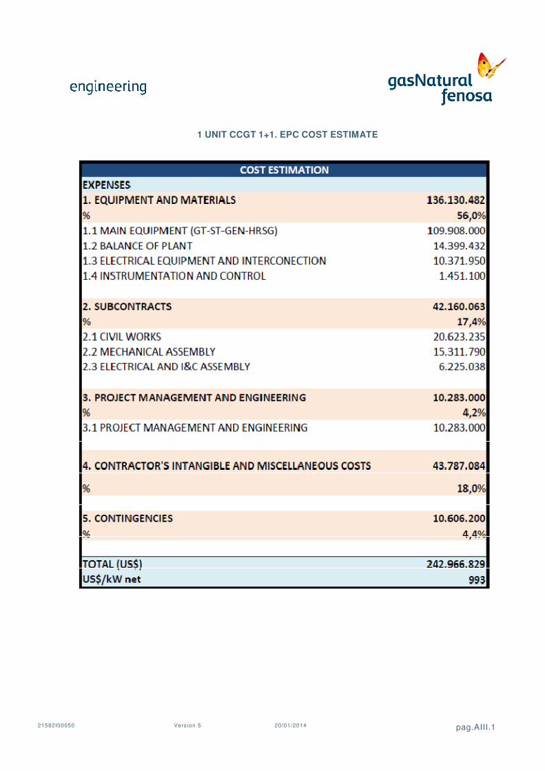
21582I00050 Version 5
n 5 20/01/2014
1 UNIT CCGT 1+1. EPC COST ESTIMATE
pag.AIII.1

21582I00050 Version 5
n 5 20/01/2014
2 UNITS CCGT 1+1. EPC COST ESTIMATE
pag.AIII.2

21582I00050 Version 5
APPENDIX IV: IMPLEMENTATION
n 5 20/01/2014
IMPLEMENTATION SCHEDULE
pag.AIV.0

Id TASK1 ENGINEERING
2 Basic Engineering3 Detailed Engineering and Construction Supervision4 SUPPLY AND CONSTRUCTION
5 CIVIL WORKS
6 Power Plant Civil Works7 Foundations of GT 18 Foundations of GT 29 Foundations of ST 1
10 Foundations of ST 211 Foundations of HRSG 112 Foundations of HRSG 213 EQUIPMENT AND MECHANICAL SYSTEMS
14 Supply and Transport15 ASSEMBLY
16 Assembly of GT 117 Assembly of GT 218 Assembly of HRSG 119 Assembly of HRSG 220 Assembly of ST 121 Assembly of ST 222 BALANCE OF PLANT23 ELECTRICAL AND INSTRUMENTATION & CONTROL
EQUIPMENT
24 Supply and Transport25 Electrical and I&C Installation26 COMMISSIONING
27 Testing and Commissioning CCGT - 128 Testing and Commissioning CCGT - 229 Provisional Acceptance CCGT - 130 Provisional Acceptance CCGT - 2
-1 1 2 3 4
TAKHIATASH TPP CCGT UNITS (PHASES I & II) CONSTRUCTION SCHEDULE

21582I00050 Version 5
APPENDIX V: GENERAL
n 5 20/01/2014
GENERAL LAY-OUT
pág. V. 0

11%
32,2
16,5
3,7
9,4
4,5
3,9
3,8
14,1
3,4
10,7
3,3
3,1
5,4
3,8
8,0
4,1
Условные обозначения:
Повторяемость в % ,
Скорость
С
А