459-475 hose assemblies
TRANSCRIPT

HOSE
FITTINGS
QUICK COU
PLINGS
ADAPTERS EQU
IPMEN
T & ACCESSORIES
ASSEMBLIES
INSTALLATION
& M
AINTEN
ANCE
APPENDIX
ASSEMBLIES
459
S SIze – I.D., O.D., and length of the assembly
T TeMPeraTure – includes temperature of fluid conveyed and the climatic conditions
a aPPLICaTION – the conditions of use, including abrasion, flexing and routing
M MaTerIaL – type of material conveyed, including composition and concentration
P PreSSure – hose assembly working pressure and surge or back pressure
e eNDS – definition of the fitting, including thread type, gender, bent tube, swivel and orientation
D DeLIVery – time allowed for delivery, including testing, quality assurance and packaging
To assist in obtaining and conveying information regarding the application, a copy of the S.T.A.M.P.E.D. application form is included in this catalog. This inquiry sheet can be sent to any Goodyear Engineered Products authorized distributor for a hose recommendation.
PLeaSe NOTe:A hose should always be selected based on its ratedworking pressure. Do not use minimum burst pressure as a guideline in selecting
the hose. Minimum burst pressure decreases over the use and life of the hose. A hose should be selected based on its rated working pressure to provide a normal service life. In addition, always select a hose by giving consideration to its recommended temperature limits. Hose service life is reduced if the tem-peratures of the fluids being conveyed or ambient temperatures exceed the recommended limits.
In order to obtain the best service from any particular hose application, two important conditions must be fulfilled.
1) Select the right hose for the job.2) Make sure that it is fitted correctly and used in the
proper manner.
Carefully consider the application requirements. A helpful guide is the S.T.A.M.P.E.D. process. S.T.A.M.P.E.D. is an acronym and stands for the seven major information areas required to provide a quality hose assembly.
SELECTiNG THE PrOPEr HOSE ASSEMBLY

APPE
NDI
X IN
STAL
LATI
ON &
MAI
NTE
NAN
CE
ASSE
MBL
IES
EQU
IPM
ENT
& A
CCES
SORI
ES
ADAP
TERS
QU
ICK
COU
PLIN
GS
FITT
INGS
H
OSE
ASSE
MBL
IES
460
PreSSure(S) Working Pressure (including surges)
Burst Pressure
Suction or Vacuum Requirements
Velocity
Impulse
eNDS & FITTINgS Type of Threads
Male/Female
Reusable/Nonreusable
Material for Fittings
Swivel or Non-Swivel
Straight or Bent Tube
Fitting 1 & 2 Orientation
Other
Cut to Length
Crimp Specs or Crimper Used
DeLIVery Lead Time
Quantity
Stock/Nonstock
Special Print
Special Packaging
OTHer INFOrMaTION Customer: Date:
Customer No.:
Ship To:
Bill To:
Telephone: Fax:
S.T.A.M.P.E.d. FOrM
SIze I.D.
O.D.
Hose Length (OAL or uncpld. lgth.)
Tolerances
TeMPeraTure of Material Being Conveyed
(high, low, ambient)
of Outside Exposure (high, low, ambient)
Intermittent?
Constant?
Sub-Zero Exposure
aPPLICaTION(S) Indoor and/or Outdoor Use
Intermittent or Continuous Use
Flexibility Required (min. bend radius)
Movement (static, vibrations, flexing)
external Conditions: Abrasion
Oil
Solvents
Acid
Ozone
Electrical/Static Conductive
Oil resistance: Tube
Cover
Flame Resistance
Noncontaminating Materials
Hose Currently in Use
Current Hose Service Life/Failure Description
Service Life Desired
MaTerIaL(S) BeINg CONVeyeD Solids (size, description)
Gaseous (volatility, inert) Liquids (flammability, causticity, acid) alkaline, solution/concentration)
Chemical Names (generic)
Bolded block areas MUST be filled out on all inquiries.

HOSE
FITTINGS
QUICK COU
PLINGS
ADAPTERS EQU
IPMEN
T & ACCESSORIES
ASSEMBLIES
INSTALLATION
& M
AINTEN
ANCE
APPENDIX
ASSEMBLIES
461
IdentifyingHoseI.D.In the case of a hose assembly replacement, the inside diameter (I.D.) of the hose can be obtained from the existing assembly. The I.D. may be printed on the layline of the hose or may have to be measured. Before cutting the assembly, measure the overall assembly length and record the orientation of the fittings. See the following sections on how to measure overall assembly length and the offset angle between the two fittings. If the I.D. of the hose has not been determined, utilize the Hose I.D. Selection Nomograph in the Appendix. The chart will yield a hose I.D. recommendation based on flow capacity and flow velocity.
Hydraulic hose size or inside diameter is sometimes referred to as the “Dash Size.” The Dash number is the I.D. of the hose in sixteenths of an inch. For example, a 1/4” I.D. hose, is equivalent to 4/16”. The “Dash Size” would be “-4.” A listing of the Dash sizes is shown below. Note that the Dash number applies to the hose I.D. for all hoses except SAE 100R5. In the case of SAE 100R5, the Dash number is equal to a relevant tube outside diameter (O.D.).
IdentifyingOverallAssemblyLengthUnless otherwise specified by the customer, the assembly’s over-all length is measured from the extreme end of one fitting to the extreme end of the other except for the O-ring face seal fittings, which shall be measured from the sealing face. Where elbow fittings are used, measurement shall be to the centerline of the sealing surface of the elbow end.
assembly Length Measurements
l
OverallAssemblyLength
Male Ends
Female Swivel Ends(except O-ring Face Seal)
Measure to sealing surface.
l
BentStemSwivelFemaleEnds
l
Flange Ends
l
SwivelO-RingFaceSealEnds
Measure to seat face.
* SAE Dash Size equals O.D. of the tubing, which has approximately the same I.D. as the hose, expressed in 1/16”.
dEFiNiNG HOSE ANd ASSEMBLY LENGTH
HoseI.D. SAEDashSize* (except Sae 100r5) (Sae 100r5) Dash No. in mm in mm -2 1/8 3.2 -3 3/16 4.8 -4 1/4 6.4 3/16 4.8 -5 5/16 7.9 1/4 6.4 -6 3/8 9.5 5/16 7.9 -8 1/2 12.7 13/32 10.3 -10 5/8 15.9 1/2 12.7 -12 3/4 19.0 5/8 15.9 -14 7/8 22.2 -16 1 25.4 7/8 22.2 -20 1 1/4 31.8 1 1/8 28.6 -24 1 1/2 38.1 1 3/8 35.0 -32 2 50.8 1 13/16 46.0 -36 2 1/4 57.6 -40 2 1/2 63.5 2 3/8 60.3 -48 3 76.2 -56 3 1/2 88.9 -64 4 101.6 -72 4 1/2 115.2

APPE
NDI
X IN
STAL
LATI
ON &
MAI
NTE
NAN
CE
ASSE
MBL
IES
EQU
IPM
ENT
& A
CCES
SORI
ES
ADAP
TERS
QU
ICK
COU
PLIN
GS
FITT
INGS
H
OSE
ASSE
MBL
IES
462
Determining Hose Cut LengthThe hose cut length for a hose assembly is calculated by sub-tracting the cut-off factor (distance from the bottom of the ferrule or collar to the end of the fitting or an internal sealing surface), denoted as “C” cut-off in the tables, from the actual assembly length required.
The “C” cut-off factor can be obtained from the fitting product tables. An example is shown below.
MeasuringtheOffsetAngleThe offset angle between two fittings is the number of degrees measured in a clockwise direction between the fitting nearest the viewer and the farthest end fitting. Tolerances on the offset angle are +/- 3 degrees for assemblies up to 24 inches long and +/- 5 degrees for assemblies 24 inches and longer.
The following illustration shows the clockwise angle separation between a “close” fitting and a “far” fitting. The “close” fitting would be defined as the fitting closer when looking at an assembly end to end. The “far” fitting would be defined as the fitting on the far end of the assembly when looking at an assembly end to end. The far end is used as the reference point and the “close” end establishes the angular difference.
dEFiNiNG HOSE ANd ASSEMBLY LENGTH
Hose Thread Thread “C”Cut-Off Stem HoseI.D. Dash Size Dash Factor Hex PartNo. (in) (mm) Size (in-TPI) Size (mm) (mm)
JIC Solid Male 37 3/8 9.5 -6 9/16-18 -6 26.3 17
Hose Cut Length
OverallAssemblyLength
C1 C2
assembly Length Tolerance Tolerance Tolerance (+/- in) (+/- in) (+/- mm)
Up through 12 inches (304.8mm) 0.13 1/8 3.2Over 12 through 18 inches (304.8 through 457.2mm) 0.19 3/16 4.8Over 18 through 36 inches (457.2 through 914.4mm) 0.25 1/4 6.4Over 36 inches (914.4mm) 1% 1% 1%
FarEndReferenceMeasuringClockwise
Far End
Close End
ClockwiseMeasurement(Degrees)
Knowing the overall length of the assembly desired, you subtract the “C” cut-off factor for each fitting from the overall length to obtain the hose cut length.
CutHoseLength=AssemblyOverallLength–(C1+C2)
C1 and C2 are cut-off factors for each end. The “C” dimension may differ for each end, depending on the fitting. In certain situations, the sealing surface of JIC swivels and O-ring face seals should be considered when calculating overall length.
Hose assemblies should be manufactured to the following length tolerances.
HOSE
FITTINGS
QUICK COU
PLINGS
ADAPTERS EQU
IPMEN
T & ACCESSORIES
ASSEMBLIES
INSTALLATION
& M
AINTEN
ANCE
APPENDIX
ASSEMBLIES
463
Hose assembly Instructions ultra-Crimp™ 1-Piece Crimped Fitting1. Determine correct hose length from desired hose assembly
length and “C” dimension. The “C” dimension, or cut-off fac-tor, can be found in the fitting tables. More information on using the “C” dimension can be found in the previous sub-topic, “Defining Hose and Assembly Length.”
2. Cut hose to required length using a cut-off saw or a circular abrasive cut-off wheel. The preferred choice would be the steel wheel with a cooling agent. Care should be taken in not overheating the hose, which can cause deformation of the hose and create difficulty when inserting the hose fittings. For textile-reinforced hose, a guillotine-style cutter may be used.
5. In certain situations, skiving may be required. Skiving is the process of removing the portion of hose cover that lies directly under the coupling ferrule. This allows the metal fitting to be coupled directly on the hose reinforcement. Skiving is further discussed in the following section under the subtopic of “Internal and External Skiving.”
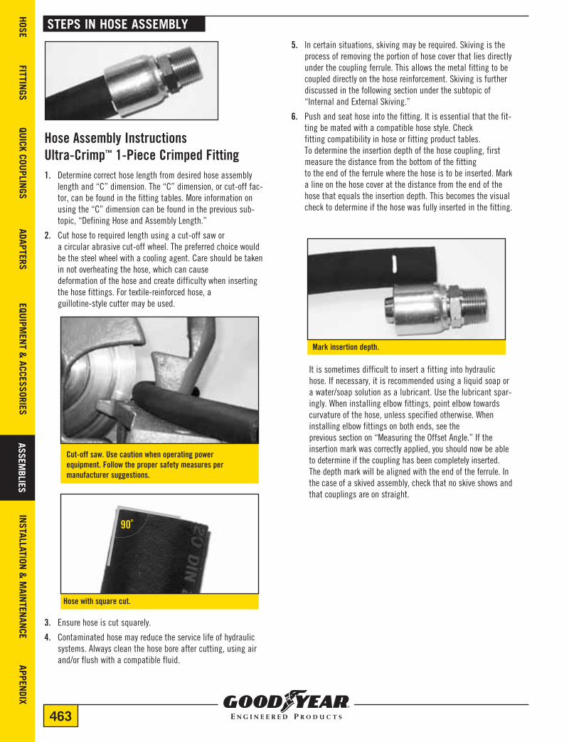
6. Push and seat hose into the fitting. It is essential that the fit-ting be mated with a compatible hose style. Check fitting compatibility in hose or fitting product tables. To determine the insertion depth of the hose coupling, first measure the distance from the bottom of the fitting to the end of the ferrule where the hose is to be inserted. Mark a line on the hose cover at the distance from the end of the hose that equals the insertion depth. This becomes the visual check to determine if the hose was fully inserted in the fitting.
3. Ensure hose is cut squarely.
4. Contaminated hose may reduce the service life of hydraulic systems. Always clean the hose bore after cutting, using air and/or flush with a compatible fluid.
It is sometimes difficult to insert a fitting into hydraulic hose. If necessary, it is recommended using a liquid soap or a water/soap solution as a lubricant. Use the lubricant spar-ingly. When installing elbow fittings, point elbow towards curvature of the hose, unless specified otherwise. When installing elbow fittings on both ends, see the previous section on “Measuring the Offset Angle.” If the insertion mark was correctly applied, you should now be able to determine if the coupling has been completely inserted. The depth mark will be aligned with the end of the ferrule. In the case of a skived assembly, check that no skive shows and that couplings are on straight.
STEPS iN HOSE ASSEMBLY
Hosewithsquarecut.
90˚
Markinsertiondepth.
Cut-offsaw.Usecautionwhenoperatingpower equipment.Followthepropersafetymeasuresper manufacturersuggestions.

APPE
NDI
X IN
STAL
LATI
ON &
MAI
NTE
NAN
CE
ASSE
MBL
IES
EQU
IPM
ENT
& A
CCES
SORI
ES
ADAP
TERS
QU
ICK
COU
PLIN
GS
FITT
INGS
H
OSE
ASSE
MBL
IES
464
8. Place hose and fitting into the crimp machine. Crimp ferrule to predetermined diameter. Refer to the Goodyear Engineered Products Crimp Specifications Manual for proper crimp diameters and the crimper operator’s manual for further instructions on how to properly and safely operate the crimper.
STEPS iN HOSE ASSEMBLY
7. Before crimping hose fitting, verify the tooling setup and install the proper die set. Read the Crimp Chart, per Goodyear Engineered Products recommendations, and dial in the correct crimp diameter.
9. Remove assembled end and check crimp diameter with caliper or micrometer. Crimp diameter should be measured at the center of the ferrule. Measure the smooth portion of the ferrule and not the ridges. Visually check for cracked, cocked or damaged fittings.
Fitting inserted on hose.
Alwaysverifyproperdieset.
Insert die set in crimper.
Set crimp diameter.
Insert hose assembly into crimper die set.
Crimphose/fittingassembly.
Verifycrimpdiameterwithcalipers.

HOSE
FITTINGS
QUICK COU
PLINGS
ADAPTERS EQU
IPMEN
T & ACCESSORIES
ASSEMBLIES
INSTALLATION
& M
AINTEN
ANCE
APPENDIX
ASSEMBLIES
465
10 Some applications require the addition of a protective outer sleeving or strain reliefs. If this is a requirement, the most appropriate time to assemble is before the second end fitting is applied. Choose the appropriate product for the specific application. When cutting product to length, allow for flexing and bending of the hose.
11 Even if not required, it is a good practice to examine and audit the assembly before delivery or use. Records should be maintained. The level of inspection should be in compliance with the quality plan.
a) Inspection—Visual, dimensional, and proof pressure testing in accordance with SAE J517 or SAE J343. b) Clean or flush of the assembly to remove plating dust, rubber chips, etc. c) Apply caps, if required, to protect fitting threads and keep out contamination. d) Apply labels or specific markings, if required.
e) Package the assembly properly.
FinalInspectionChecklist• Bulge behind the fitting
• Cocked fittings
• Cracked fittings
• Rusted fittings
• Exposed reinforcement
• Freedom of swivels
• General appearance of the assembly
• Internal contaminants
• Restriction of the tube
RecommendedInspectionEquipment• Worktable suitable for inspection
• Tape measure to measure overall length
• Calipers for measuring crimp diameter
• Pi tape to measure outside diameter
• Plug gauges for measuring inside diameter
• Protractor device for measuring angle orientation of bent tube fittings
• Magnifying glass and light to view inside of assemblies
• Burst and proof pressure tester
STEPS iN HOSE ASSEMBLY
Hose assembly Instructions uni-Crimp™ 2-Piece Crimped Fitting1. Determine correct hose length from desired hose assembly
length and “C” dimension. The “C” dimension, or cut-off factor, can be found in the fitting tables. More information on using the “C” dimension can be found in the previous subtopic, “Defining Hose and Assembly Length.”
2. Cut hose to required length using a cut-off saw or a circular abrasive cut-off wheel. The preferred choice would be the steel wheel with a cooling agent. Care should be taken in not over-heating the hose, which can cause deformation of the hose and create difficulty when inserting the hose fittings. For textile-reinforced hose, a guillotine-style cutter may be used.
Cut-offsaw.Usecautionwhenoperatingpowerequipment.Followthepropersafetymeasurespermanufacturer suggestions.
Hosewithsquarecut.
90˚
3. Ensure hose is cut squarely.

APPE
NDI
X IN
STAL
LATI
ON &
MAI
NTE
NAN
CE
ASSE
MBL
IES
EQU
IPM
ENT
& A
CCES
SORI
ES
ADAP
TERS
QU
ICK
COU
PLIN
GS
FITT
INGS
H
OSE
ASSE
MBL
IES
466
STEPS iN HOSE ASSEMBLY
4. Contaminated hose may reduce the service life of hydraulic systems. Always clean the hose bore after cutting, using air and/or flush with a compatible fluid.
5. In certain situations, skiving may be required. Skiving is the process of removing the portion of hose cover that lies directly under the coupling ferrule. This allows the metal fitting to be coupled directly on the hose reinforcement. Skiving is further discussed in the following section under the subtopic of “Internal and External Skiving.”
6. The 2-piece crimped fitting consists of a ferrule and a stem insert. It is essential that the fitting be mated with a compatible hose style. Check fitting compatibility in hose or fitting product tables. Screw and/or push ferrule onto the hose until hose bottoms into the ferrule.
8. Before crimping hose fitting, verify the tooling setup and install the proper die set. Read the Crimp Chart, per Goodyear Engineered Products recommendations, and dial in the correct crimp diameter.
7. Push the stem insert into the hose I.D. Shoulder of the stem should make contact with ferrule. It is sometimes difficult to insert the stem into hydraulic hose. If necessary, it is recommended using a liquid soap or a water/soap solution as a lubricant. Use the lubricant sparingly. When installing elbow fittings, point elbow towards curvature of the hose, unless specified otherwise. When installing elbow fittings on both ends, see the previous subtopic on “Measuring the Offset Angle.”
Alwaysverifyproperdieset.
Install the proper die set.
Set crimp diameter.
Pushferruleontohose.
Push stem into hose I.D.

HOSE
FITTINGS
QUICK COU
PLINGS
ADAPTERS EQU
IPMEN
T & ACCESSORIES
ASSEMBLIES
INSTALLATION
& M
AINTEN
ANCE
APPENDIX
ASSEMBLIES
467
9. Place hose and fitting into the crimp machine. Refer to the Goodyear Engineered Products Crimp Specifications Manual for proper crimp diameters and the crimper operator’s manual for further instructions on how to properly and safely operate the crimper.
10. Remove assembled end and check crimp diameter with caliper or micrometer. Crimp diameter should be measured at the center of the ferrule. Measure the smooth portion of the ferrule and not the ridges. Visually check for cracked, cocked or damaged fittings.
STEPS iN HOSE ASSEMBLY
Hose assembly Instructions Field-grip™ FittingsGoodyear Engineered Products Field-Grip reusable hose fittings must be carefully matched to Goodyear Engineered Products hose. Use Field-Grip fittings only designed specifically for Goodyear Engineered Products hose. Use the correct socket with a given hose. Specific fittings and their hose application can be found in the fitting tables.
1. Determine correct hose length from desired hose assembly length and “C” dimension. The “C” dimension, or cut-off factor, can be found in the fitting tables. More information on using the “C” dimension can be found in the previous subtopic, “Defining Hose and Assembly Length.”
2. Cut hose to the required length using a cut-off saw or a circular abrasive cut-off wheel. The preferred choice would be a steel wheel with a cooling agent. Care should be taken in not overheating the hose, which can cause deformation of the hose, creating difficulty when inserting the hose fittings.
Cut-offsaw.Usecautionwhenoperatingpowerequipment.Followthepropersafetymeasurespermanufacturer suggestions.
11. Even if not required, it is a good practice to examine and audit the assembly before delivery or use. Records should be main-tained. The level of inspection should be in compliance with the quality plan.
a) Inspection—Visual, dimensional, and proof pressure testing in accordance with SAE J517 or SAE J343. b) Clean or flush of the assembly to remove plating dust, rubber chips, etc. c) Apply caps, if required, to protect fitting threads and keep out contamination. d) Apply labels or specific markings, if required. e) Package the assembly properly.
Refer to the Final Inspection Checklist and Recommended Inspection Equipment previously listed in “Hose Assembly Instructions Using a 1-Piece Crimped Fitting.”
Insert hose assembly into crimper die set.
Crimpthehose/fittingassembly.
Verifycrimpdiameterwithcalipers.

APPE
NDI
X IN
STAL
LATI
ON &
MAI
NTE
NAN
CE
ASSE
MBL
IES
EQU
IPM
ENT
& A
CCES
SORI
ES
ADAP
TERS
QU
ICK
COU
PLIN
GS
FITT
INGS
H
OSE
ASSE
MBL
IES
468
STEPS iN HOSE ASSEMBLY
4. Contaminated hose may reduce the service life of hydraulic systems. Always clean the hose bore after cutting, using air and/or flush with a compatible fluid.
5. A Field-Grip™ fitting consists of a socket and stem assembly. |t is essential the fitting be mated with a compatible hose style. Check fitting compatibility in hose or fitting product tables. Place the socket in a vice. The socket will fit over the hose cover. To determine the insertion depth for the hose, first mea-sure the distance from the bottom of the socket to the end of the socket where the hose is to be inserted. Transfer this inser-tion depth to the hose cover by measuring from the end of the hose. Mark a line on the hose cover at the distance from the end of the hose that equals the insertion depth. This becomes the visual check to determine if the hose was fully inserted in the socket.
3. Ensure hose is cut squarely.
Hosewithsquarecut.
90˚
Field-Gripfittingconsistsofastemandasocket.
Markinsertiondepth.
Socketpositionedinvice.
Applylubricanttohosecover.
Visuallycheckhosepositioninsidesocket.
6. Lightly lubricate hose cover with a mild soap solution. Screw end of hose counterclockwise until hose reaches the marked insertion depth and then back off 1/2 turn. If the insertion mark was correctly applied to the hose, you should now be able to determine if the socket has been correctly applied to the hose by using the insertion depth mark on the hose cover as a reference along with a visual check inside the socket.
HOSE
FITTINGS
QUICK COU
PLINGS
ADAPTERS EQU
IPMEN
T & ACCESSORIES
ASSEMBLIES
INSTALLATION
& M
AINTEN
ANCE
APPENDIX
ASSEMBLIES
469
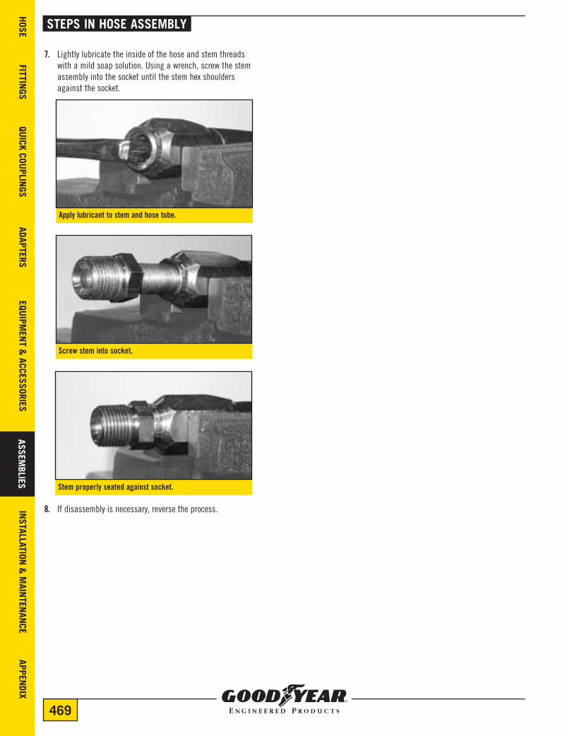
7. Lightly lubricate the inside of the hose and stem threads with a mild soap solution. Using a wrench, screw the stem assembly into the socket until the stem hex shoulders against the socket.
8. If disassembly is necessary, reverse the process.
STEPS iN HOSE ASSEMBLY
apply lubricant to stem and hose tube.
Screwstemintosocket.
Stemproperlyseatedagainstsocket.

APPE
NDI
X IN
STAL
LATI
ON &
MAI
NTE
NAN
CE
ASSE
MBL
IES
EQU
IPM
ENT
& A
CCES
SORI
ES
ADAP
TERS
QU
ICK
COU
PLIN
GS
FITT
INGS
H
OSE
ASSE
MBL
IES
470
4. With the hose cover removed, check that the wire braid or spiral reinforcement has not been displaced, damaged or cut in the skiving process.
5. Check for the proper skive length.
6. Hoses should be checked for 100% of cover removal. If necessary, rebuff skived area to clean and remove hose cover.
7. A manual, internal skiving tool that uses a knife is to be used to remove the tube material of spiral hose for installation of the Dual-Grip™ fittings. Note the correct length of tube material to be removed from the Goodyear Engineered Products Crimp Specification Manual. Set the desired skiving depth on the internal skiving tool. Make sure the tool rotates in the clockwise direction for internal skiving. Verify that the correct length of tube material has been removed. Follow specific instructions on internal skiving that would accompany the manual skiver.
8. It is important to clean hose I.D. by brushing, blowing compressed air or flushing to remove any contaminants.
Warning: Failure to completely remove the cover may result in serious personal injury or property damage due to hose ends blowing off, leakage or other failures.
InternalandExternalSkivingSkiving is the process of stripping and removing the hose cover to allow the proper installation of crimped hose ends and to ensure the best possible hose assembly.
1. At the point of skiving, the hose has been cut to the proper length. See Steps 1 and 2 in the previous hose assembly instructions.
2. Obtain length of skive per Goodyear Engineered Products specifications. Mark hose with skive length.
iNTErNAL ANd EXTErNAL SkiviNG
Markskiveonhosecover.
3. Remove the hose cover to the wire, using care not to burn, fray or damage reinforcement wires. The cover of wire-braided hoses can be removed with a buffing wheel or a hand skiver. A manual, external skiving tool that uses a knife must be used with spiral hose. Mark the length of the cover to be removed, as noted in the Goodyear Engineered Products Crimp Specifications Manual, and set skiving depth on the manual skiving tool. Make sure the manual skiver is rotated in the counterclockwise direction for external skiving. Follow specific instructions on external skiving that would accompany the manual skiver.
Cuttingskivewithbuffingwheel.Followmanufacturer’srecommendationforthesafeandproperuseoftheskiver.
Checkskivedhose.
Measureskive.

HOSE
FITTINGS
QUICK COU
PLINGS
ADAPTERS EQU
IPMEN
T & ACCESSORIES
ASSEMBLIES
INSTALLATION
& M
AINTEN
ANCE
APPENDIX
ASSEMBLIES
471
STEPS iN Gr14A ASSEMBLY
InordertomakeaqualityassemblywithGR14Ahose,thefollowinginstructionmustbefollowed:1. Tape hose before cutting as shown.
2. Slip ferrules on. Be sure they are in the correct direction. (i.e. flange side aims to the outside of the hose.)3. Push in on stem on each end.4. Remove the tape and slide the ferrule onto the stem.
Thiswillpreventthewirefromflaringoncethecutismade.Ifwireflareisallowedtooccur,theferrule will not slide onto the hose.

APPE
NDI
X IN
STAL
LATI
ON &
MAI
NTE
NAN
CE
ASSE
MBL
IES
EQU
IPM
ENT
& A
CCES
SORI
ES
ADAP
TERS
QU
ICK
COU
PLIN
GS
FITT
INGS
H
OSE
ASSE
MBL
IES
472
STEPS iN Gr14A ASSEMBLY
5. Crimp the fitting using proper die selection and setting. Be sure not to allow the ferrule to slip back onto the hose or ride up on the hub of the stem. The groove of the ferrule must line up with flange of the stem.
6. Check finished crimp diameter.

HOSE
FITTINGS
QUICK COU
PLINGS
ADAPTERS EQU
IPMEN
T & ACCESSORIES
ASSEMBLIES
INSTALLATION
& M
AINTEN
ANCE
APPENDIX
ASSEMBLIES
473
Steps in Cool Clip a/C Hose assembly1. Cut the hose to proper length with the Goodyear Engineered
Products hose cutter PN 65090.
2. Install two proper-sized clips into the clipholder. For ease of assembly, both clips should have the same orientation.
3. Place the clipholder with the two clips on the hose. Install the clipholder so that the end with the smallest hole touches the end of the hose.
STEPS iN COOL CLiP™ A/C HOSE ASSEMBLY
4. Lubricate the fitting with a generous amount of the A/C system’s lubricator oil. This is to lower the force of the insertion.
5. Insert the fitting into the hose. Ensure that the fitting is fully inserted so that there is no gap between the end of the hose, the clip retainer and the shoulder of the fitting.
6. Close both clips with the Goodyear Engineered Products clip pliers, PN GC-Pliers-0001. The pliers will automatically release when the clips have been completely closed. Start with the clip closer to the end of the hose.
7. Now you have realized a durable hose/fitting connection.Thecutmustbemadesquarelytothehoselength.
Special care should be taken when selecting the proper refrigerant hose and fittings. Goodyear Engineered Products Cool-Clip™ fittings should only be used with Goodyear Engineered Products Galaxy® 4890 hose.
Special care must be taken when working with refrigerant systems. Sudden escape of refrigerant gases may result in blindness or severe injury. Goodyear Engineered Products recommends adherence to guidelines and general practices as defined in SAE J2211 for the service containment of HFC-134a as well as all applicable EPA guidelines and procedures concerning the service of refrigerant systems.
Warning—SelectionofFittingSelection of the proper Goodyear hose and fittings for the application is essential to the proper operation and safe use of the hose and related equipment. Inadequate attention to the selection of the hose and fitting for the application can result in hose leakage, bursting or other failures which can cause serious bodily injury or property damage from spraying fluids or flying projectiles. Some of the factors involved in the selection of the proper hose and fittings are:
HOSe FITTINgS Size Compatibility Refrigerant Pressure Pressure Temperature Length Installation Design Bends Hose Size Original Equipment Corrosion RequirementsIf there are any questions as to what fitting should be used, Veyance recommends that you consult the local Field Representative or Goodyear Hydraulics Application Group for assistance.
90˚

APPE
NDI
X IN
STAL
LATI
ON &
MAI
NTE
NAN
CE
ASSE
MBL
IES
EQU
IPM
ENT
& A
CCES
SORI
ES
ADAP
TERS
QU
ICK
COU
PLIN
GS
FITT
INGS
H
OSE
ASSE
MBL
IES
474
A/C FiTTiNG CriMPiNG PrOCEdurE FOr PC125 CriMPEr
A/CFittingCrimpingProcedurefor PC125 Crimper1. Insert the pressure plate into the bottom flange of the crimper,
making sure that it is seated completely into the bottom flange.3. Place the compression ring loosely but evenly over the die set.
Make sure die set is correctly aligned.
4. Slide the pusher in place.
7. Select the appropriate Galaxy hose size and cut to the correct length using Goodyear Engineered Products Hose Cutting Tool (part #65090). Be sure the hose is cut squarely at a 90-degree angle to the hose.
8. Insert the hose end fully into the ferrule of the corresponding fitting. When completely inserted, the hose should be visible through the witness hole on the side of the ferrule.
5. Set the micrometer to the setting as shown in the Goodyear Crimp Specification Manual for the combination of hose and fitting being crimped. The metric micrometer (readings of 0 to 10) is a direct reading micrometer. The setting on the micrometer is added to the number in millimeters etched on the die ring to obtain the final crimp diameter. The adjuster, set at “0,” is the setting for the die set fully closed. For example, with a 34mm die and the micrometer set at 3.0, the finished crimp diameter would be 37.0mm (34mm + 3.0mm).
6. Attach the coupling stop, included with your crimper, to the base of the crimper.
2. Select the correct die set for the Galaxy® hose dash size/I.D. and “AC” fitting being crimped. Insert the two halves of the die set onto the pressure plate, making sure both halves are flat and level.
Be Sure To: Lubricate the contact surfaces: both bottom and outside edges of the die fingers, the inside of the compression ring and the pressure plate with the die lubricant provided with the crimper. Only use a molybdenum/graphite high-pressure grease applied sparingly to the contact surfaces. Die lubricant can be obtained from Goodyear Engineered Products using part numbers PC900-Grease-3oz or PC900-Grease-1lb. An aerosol lubricant, PC900-AerosolLube, can also be used.
GalaxyHose#I.D. PC125DieSet G4826-06 5/16” PC125-AC06 G4826-08 13/32” PC125-AC08 G4826-10 1/2” PC125-AC12 G4826-12 5/8” PC125-AC12 G4867-14 3/4” PC125-AC12
Failuretolubricatethecontactsurfaceswiththe correctlubricantwillcausethediestoseizeinthecompression ring, causing damage to the die set as well as possibly damaging the crimper.

HOSE
FITTINGS
QUICK COU
PLINGS
ADAPTERS EQU
IPMEN
T & ACCESSORIES
ASSEMBLIES
INSTALLATION
& M
AINTEN
ANCE
APPENDIX
ASSEMBLIES
475
A/C FiTTiNG CriMPiNG PrOCEdurE FOr PC125 CriMPEr
9. Insert the hose and fitting through the crimp dies. Align the foot on the coupling stop so that the foot rests on the top of the crimp die and also against the end of the fitting ferrule. Be sure the foot on the coupling stop is against the end of the ferrule and not resting on the bump of the tube above the ferrule.
10. Manually depress the compression ring, closing the die set until the hose and fitting are held loosely in the die set. Seat the compression ring evenly on the die set.
11. Recheck the fitting for the correct alignment in the die set and depress the start/stop switch. Hold the start/stop switch until the automatic stop switch shuts the pump off. Release the start/stop switch and allow the pusher to return to the retracted position.
12. Check the crimp diameter of the finished assembly with a caliper or micrometer to be certain that it is within the specifications as outlined in the Goodyear Engineered Products Crimp Specification Manual. The caliper measurement should be taken in the crimp groove between the ridges as shown.
13. Check the completed assembly to be sure that the hose is still visible through the witness hole on the fitting. Also, the crimp grooves should be centered on the fitting ferrule.
NOTe: To properly measure the crimp diameter on “AC” style fittings, your caliper should be a style having notched blades as shown here:
CauTION: The notches on the die set must be completely coveredbythecompressionringpriortostartingthe crimp.Ifthenotchesareshowing,youmustgotoalargerdieset.Crimpingwithanincorrectdiesizecouldresultinpersonalinjury.
Each die set has a limited range of diameters for which a satisfactory crimp can be obtained. Always consult the Goodyear Engineered Products Crimp Specification Manual for selecting the correct die set.
If the crimp grooves are too near the fitting end of the ferrule, or too near the hose end of the ferrule, the fitting may not seal properly and the assembly could leak. If your finished crimp assembly resembles either of the two examples shown below, the end of the ferrule was not properly positioned against the coupling stop foot, or the coupling stop foot was not resting on the top of the die set when crimped. A new assembly should be crimped, being sure to follow the procedures in Step 9.