48-749 special topics parametric modeling with bimramesh/teaching/course/48-749/doc/... · 48-749...
TRANSCRIPT

48-749 Special TopicsParametric Modeling with BIM
Fall Semester 2010 • 6-12 units • 1.30-4.20• CFA 213
Carnegie Mellon UniversitySchool of Architecture
Instructor: Ramesh Krishnamurti [email protected]
Co-Instructor: Tsung-Hsien Wang [email protected]
Co-Instructor: Tajin Biswas [email protected]
Lecture 1 Course introduction
What is BIM ?
How we use it in this course
Overview of Revit 2011
Course Introduction This course is to prepare students for modeling architectural
geometry through development of parametric schemes for architecture applications.
For students with no programming background, this course is a half-semester course, which supplies the basis of understanding parametric geometric construction mechanisms.
For all students, the full semester course is regarded as the venue for pursuing individual projects relating to advanced geometric constructions with parametric computation.
The course will use Revit Architecture 2011, Revit API and .NET framework.

Course credit (6-12) All students are initially evaluated for 6 units (half-semester
course). Students who score at least B- at mid-semester may proceed to the full semester course for credit.
The project and any accompanying preparatory assignments will be worth an additional 3 units.
Students may add to their skill and degree of difficulty by completing a Revit-based advanced parametric modeling assignment for an additional 3 units. This is required of all Computational Design students.

Course Motivation BIM tools, such as Revit, offer a parametric 3D model which
can generate information early in the design process (quantity take–offs, solar studies, day-lighting simulation, fabrication possibilities)
With more parametric control over designed components designers can explore variations, analyze design artifacts, customize components for evaluation and be more efficient.

Course schedule
Date Class Assignment
Week 1Introduction to building information modelingIntroduction to Revit Architecture 2011
Week 2BIM capabilities MA 1Construction of a simple project
Week 3BIM as used in the AECM domain Revit (Lighting Studies, material Takeoff) MA 1 due/MA 2
Week 4Type of familiesRevit Modeling 3d Families I
Week 5Categories and ParametersRevit Modeling 3d Families II MA 2 due/MA 3
Week 6Encoding Design RulesRevit Modeling 3d Families III
Week 7PrototypingRevit Modeling 3d Families IV MA 3 due

Course scheduleDate Class AssignmentWeek 8 Introduction to .NET C# I Project
Week 9Introduction to .NET C# II
Prog. Assignment1Windows Form applications
Week 10 Introduction to REVIT 2011 API I Project proposal
Week 11 Introduction to REVIT 2011 API IIProg. Assignment 1DueProg. Assignment II
Week 12Database and SQL, LEED credit evaluations I
Week 13 Thanksgiving Holiday (No Class)Week 14 Review/Working session
Week 15 Final PresentationProject DueProg. Assignment II due

What is BIM ?From Information Science Definition
As a noun – Building Information Model“An instance of a populated data model of buildings that contains multi-disciplinary data specific to a particular building which they describe unambiguously”
As a verb – Building Information Modeling
“The act or process of creating a Building Information model”

What is BIM ? The acronym BIM (Building Information Model(ing)) was
coined in the early 2002 (attributed to Phil Bernstein and Jerry Laserin though the concept predates this by at least 15 years)
BIM relies on the creation and collection of interrelated computable information about a building project

What is BIM ?
BIM processes revolve around virtual models that make it possible to share information through out the building industry
http://bim.arch.gatech.edu/data/reference/hok.pdf

What is BIM? These models are embedded with data, which, when
shared among design team members, can reduce errors and facilitate an integrated process.
The federal government has predicted savings of $15.8 billion annually from an integrated process by using BIM. (BIG BIM little bim-Finith Jernigan)

What is BIM? BIM is an information based system that builds long term
value and advances innovation
It can improve how projects are designed and built
It improves the environment and builds economic value
BIM can be looked at in this course as “Beyond Information Models” to understand the nature of the concept
For clarity we will use bim to represent applications−Archicad, Microstation/GC and Revit bim tools

What BIM is not BIM is neither a single building model
nor a single database(series of interconnected models and databases)
BIM is neither perfect nor a panacea

What BIM is not BIM does not have to be only 3D.
Example : A spread sheet can be a BIM
BIM is not complete
BIM is not a software application−(eg, Revit, ArchiCAD or Microstation/GC etc)

How BIM is used pragmatically As a distributed relational parametric database So where does the knowledge manifest itself?

How BIM is used in this course Focus is on the power of bim tools primarily but not limited to
evaluate facets of sustainable building design
Using information from a BIM we are able to count, sort and calculate different requirements set by sustainable building rating systems
Material resources Recycled material content
Water resources Water usage and savings
Energy use Energy use reduction by optimizing façade/envelope of building

How we have used BIM Sustainable building rating systems are defined as tools which
examine the performance or expected performance of a ‘whole building’ and translate that examination into an overall assessment that allows for comparison against other buildings
LEED (Leadership in Energy and Environmental Design) − USGBC
BREEAM (Building Research Establishment’s Environmental Assessment Method) − UK
CASEBEE (Comprehensive Assessment System for Building Environmental Efficiency) − Japan

Overview of rating systems
19
GeneralAssessment Area
LEED 3.0 Green Star BREEAM
Management Management Management
Energy & Atmosphere Energy Energy Energy
Emissions Emissions Pollution
Sustainable Sites Sustainablesites
Land Use and Ecology
Land Use and Ecology
Transportation Transportation
Water Efficiency Water Efficiency Water Water
Indoor Air Quality Indoor Air Quality
Indoor EnvironmentalQuality
Health and Well Being
Quality of Service
Materials and Resources
Materials and Resources
Materials Materials
Innovations Innovations Innovation
Culture and Heritage

BIM example 1

Structure of our Application

Dot Net Application (Automating LEED Evaluations)
22
Evaluation Status Display
Navigation Column
Status Window
Test Building Model –407 N. Craig St.

Evaluation example- calculating LEED SS 2 (site density)
23

24
350’
A B C
DEFFG
H
I
J
KL
M N
OP
Evaluation example- calculating LEED SS 2 (site density)

Ongoing Evaluations- calculating LEED SS 2 (creating mass model for site density)
25
A
B C
DE
FG
H
IJ
KL
MN
O PDevelopment Density
Revit as a bim software Creates a 3D ‘parametric’ model which produces an
abstraction of plans, elevations, sections and schedules using databases.
Propagates and manages changes throughout these databases so that a change to any part of the database is reflected in all other associated parts of the database
Captures and preserves information for collaboration and reuse by additional industry-specific applications

Revit as a bim software Bidirectional Associatively
All views (eg, plan, section, schedule) use the same database
No updates needed (automatic)
Parametric Relationships
Software manages and coordinates changes
Example: You have equally spaced windows across an elevation. Length of elevation changes. The spacing between the windows changes but the relationship of equal spacing is maintained
Revit vs. AutoCAD Revit is a true architectural model (not just geometry)
Revit is parametric
Revit uses “families” not blocks (eg, doors, windows)
Revit uses alignment instead of osnaps
Revit has multiple design views (plan, elevation, perspective, section)

Revit vs. AutoCAD
No command line or layers in Revit Visibility controlled by categories
Revit uses single file, multiple users projects
Revit imports/exports AutoCAD file type (.DXF and .DWG)

Revit Fundamentals Revit ‘Parametric’ Elements
Every Element in Revit is considered a family
Each family belongs to a category
(2D/3D)
(2D/3D)

Revit Fundamentals- ModelManage> Object Styles
Model categories include elements like walls, floors, roofs etc.
Model elements appear by default in all view-plan, elevations, section and 3D views
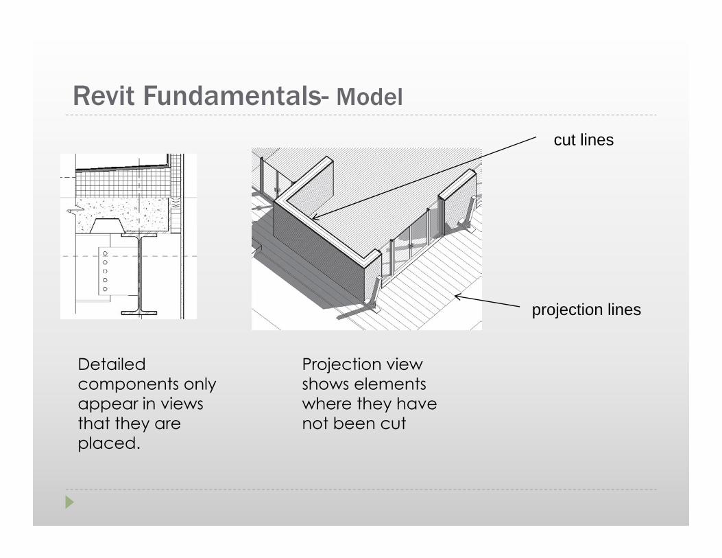
Detailed components only appear in views that they are placed.
Projection view shows elements where they have not been cut
Revit Fundamentals- Model
Detailed components only appear in views that they are placed.
cut lines
projection lines
Projection view shows elements where they have not been cut

Revit Fundamentals- AnnotationAnnotation categories include annotations, symbols and descriptive data
Examples-dimensions, tags, callouts
Annotations such as grids, sections, levels are 2D graphics but have 3D characteristics as they appear in other views
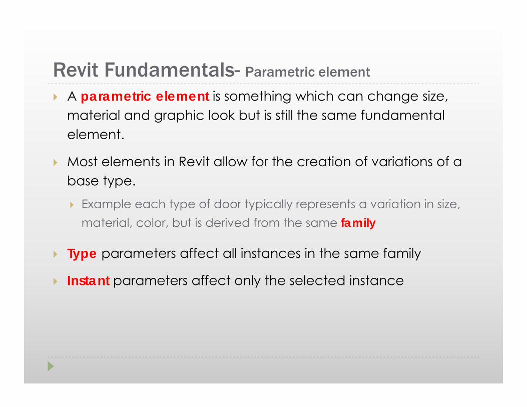
Revit Fundamentals- Parametric element
A parametric element is something which can change size, material and graphic look but is still the same fundamental element.
Most elements in Revit allow for the creation of variations of a base type.
Example each type of door typically represents a variation in size, material, color, but is derived from the same family
Type parameters affect all instances in the same family
Instant parameters affect only the selected instance
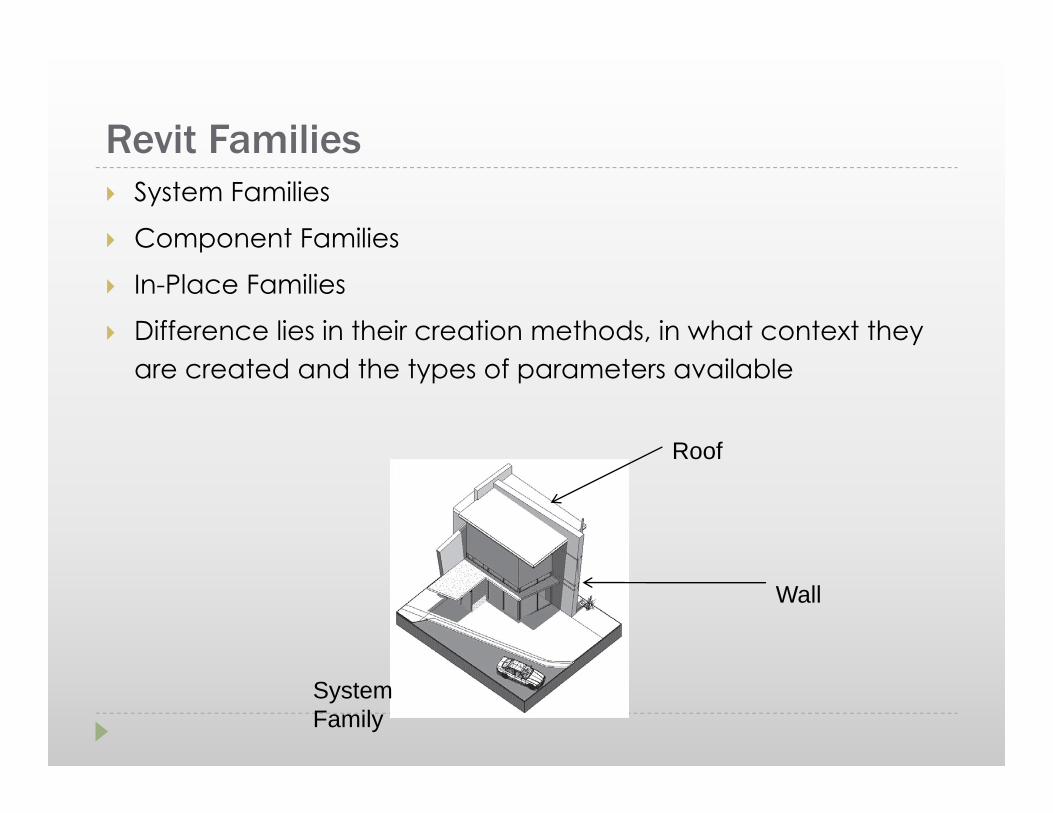
Revit Families System Families
Component Families
In-Place Families
Difference lies in their creation methods, in what context they are created and the types of parameters available
Roof
Wall
System Family

Revit Families- System Families They are made of limited categories−
walls, roofs, floors, ceilings, stairs, railings, mechanical equipments and topo surfaces
They have different creation methods: Walls − draw/place a wall
Floor/Roof − has to be in Sketch Mode then it generates a 3D model
Floors and railings more detail in Sketch Mode that has additional features that floors do not have

Revit Families- Component Families Components or standard families are created outside the
project environment using the family editor. These are stored in an external library which can be loaded into the project.
Each component belongs to a specific Revit category.
They have their own extension .rfa
Windows
EntourageComponent Family

Revit Families- Component Families Go to insert tab > Choose Load Family

Revit Families- In Place Families In place families are custom elements that are specific to a
project and the conditions of the project.
The model grays out and becomes in-selectable when such families are made.
Example, a non vertical wall shape or skewed mullion
These can be copied from project to project
These do not interface well with energy modeling, day lighting tools or direct-to-fabrication .

Family Creations & Manipulations- component
Image by Taihung Chen & Chingyi Chou, GSAPP, presented at NYV Revit User Group Meeting (designReform.com)
Wall Family _ Corner

Family Creations & Manipulations -panels
Image by Milan Dale & Micah Roufa, GSAPP, presented at NYV Revit User Group Meeting (designReform.com)
Curtain Wall Family 01 Curtain Wall Family 02
Introduction to Revit 2011
Cluster: Baker 140C
OR
Download from:http://students.autodesk.com/

Revit 2011 Interface Overview

Revit 2011 Interface Overview
RibbonPanel
Application menu
Info Center
Project browser
Status bar View Control bar Drawing Area
Quick access toolbar
Properties

Revit 2011 Interface, Application menu The big purple R on top left
It allows to open and create new/ existing projects/families
Allows to save and export in various formats RVT = Revit Projects RTE= Revit Templates RFA = RevitFamily

Revit 2011 Interface, Application menu Option allows the following settings
File location
Settings relevant to steering wheels
The view cube
Spelling
Macro
General settings-such as saving time intervals

Revit 2011 Interface, Ribbon
The ribbon is organized in tabs and panels Nine Tabs
Home Insert Annotate Structure (this is new in 2011) Massing and Site Collaborate View Manage Modify

Revit 2011 Interface, Ribbon
Home- contains all tools to create 3D elements
Insert – imports and manages CAD files and Raster images
Annotate – Contains all tools for adding 2D elements to describe building model in a project

Revit 2011 Interface, Ribbon
Massing and Site – creating and modifying conceptual mass models
Collaborate – Tools that aid in collaboration on the same project
Structure – Tools that deal with structural elements and their details

Revit 2010 Interface, Ribbon
View – Many views are different queries into the Revit database
Manage – Design options as well as project related settings are located here
Modify – Once elements are created they have to be changed or edited

Revit 2011 Interface, View window
Steering wheel and View Cube
View Controls

Revit 2011 Interface, View window
View Controls
Temporary/hide
Show crop region
Crop view
Graphics display option
Model graphic style
Reveal hidden elements
Detail level
Scale
Steering wheelAllows 2D zoom, pan and rewind

Revit 2011 Interface, View windowNavigation Wheel (F8)
Right click and choose Options… to set the Steering Wheel parameters

Revit 2011 Interface, View window
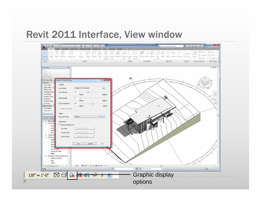
Revit 2011 Interface, View window
Graphic display options

Revit 2011 Interface- Units and settings Units for the following can be set for a project by going to
the Manage Tab> select Project Units
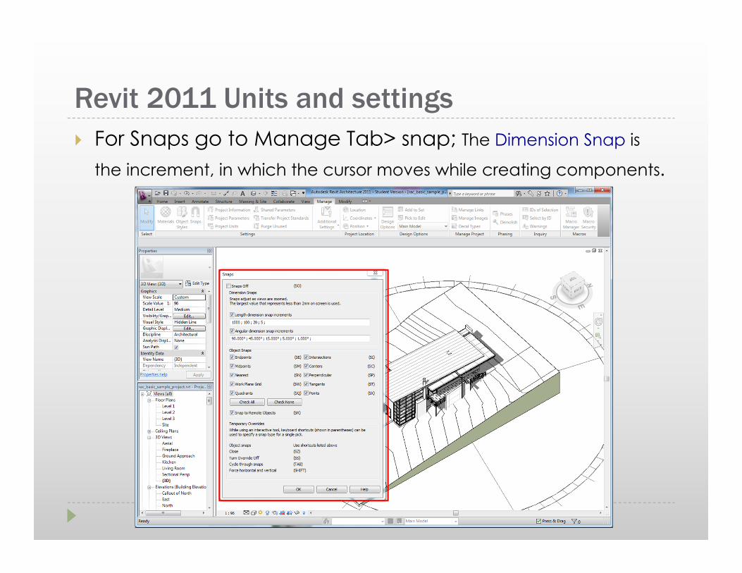
Revit 2011 Units and settings For Snaps go to Manage Tab> snap; The Dimension Snap is
the increment, in which the cursor moves while creating components.

Revit 2011 Project browser
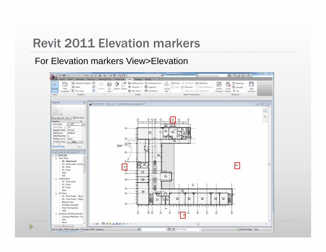
Revit 2011 Elevation markersFor Elevation markers View>Elevation

Revit 2011 Project windows

Revit 2011 Lesson1 Exercise 1- 3
Open, Save, and Close an Existing Project
Exercise 4 Creating a New Project
Set units
Set project information
Exercise 5 Using Zoom & Pan to View Drawings
Exercise 6 Using Revit’s Help System

Exercise 1-3Open Project Basic Sample Project

Exercise 1-3Open Another Project : Advanced Sample Project

Exercise 1-3And another project

Exercise 1-3Toggle between projects

Exercise 4 Create a new Revit project
Template Files Units set (e.g. Imperial or Metric)
Wall, door, and window family styles defined
Title blocks inserted

Exercise 5Using Zoom and Pan to View a Drawing

Exercise 6Use Revit’s Help System