48510 09 ch09 p9-1-9-40 1. - cengage up the drawing step 1: start the autocad program. step 2: to...
TRANSCRIPT
CHAPTER
9Hatching andBoundaries
PROJECT EXERCISE
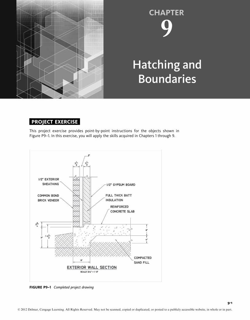
This project exercise provides point-by-point instructions for the objects shown inFigure P9–1. In this exercise, you will apply the skills acquired in Chapters 1 through 9.
FIGURE P9–1 Completed project drawing
9-1
© 2012 Delmar, Cengage Learning. All Rights Reserved. May not be scanned, copied or duplicated, or posted to a publicly accessible website, in whole or in part.

In this project, you will do the following:
• Set up the drawing, including Limits, Units, and Layers.
• Use the LINE, PLINE, and BHATCH commands to create objects.
• Use the ARRAY command to create objects from existing objects.
• Use the FILLET and TRIM commands to modify objects.
SET UP THE DRAWINGStep 1: Start the AutoCAD program.
Step 2: To create a new drawing, invoke the NEW command from the Quick Accesstoolbar.
AutoCAD displays the Select Template dialog box. Select acad.dwt as the tem-plate file and choose Open. AutoCAD creates a new drawing. Set the Units,Limits, Snap, and Grid to the values shown in the Settings/Value table.
Step 3: Invoke the LAYER command from the Layer panel. AutoCAD displays theLayer Properties Manager dialog box. Create 10 layers, rename them asshown in the table, and assign appropriate colors and linetypes.
Settings Value
UNITS ArchitecturalLIMITS Lower left corner: -2 0-0 00,-2 0-6 00
Upper right corner: 4 0-0 00,3 0-6 00
GRID 1 00
SNAP ½ 00
LAYERS NAME COLOR LINETYPEBorder Cyan ContinuousSlab White ContinuousText Blue ContinuousBrick section White ContinuousConcrete White ContinuousEarth White ContinuousHatch boundary Red ContinuousInsulation Green ContinuousSand White ContinuousWall White Continuous
HATCH PATTERNS NAME LAYER SCALE ANGLEAR-CONC Concrete 0 0-0½ 00 0FLEX Insulation 0 0-3 00 45ANSI31 Brick section 0 0-6 00 0EARTH Earth 0 0-9 00 45AR-SAND Sand 0 0-0½ 00 0
DRAWING THE CONCRETE SLAB, BRICK WALL,AND FRAME WALLStep 4: Set Slab as the current layer. Invoke the PLINE command with a width of
0.125 to draw the concrete perimeter and a width of 0.0 to draw the “break”line, as shown in Figure P9–2. Figure P9–1 shows all the required dimensionsto draw the layout. After you draw the layout, the drawing should look likeFigure P9–2.
© 2012 Delmar, Cengage Learning. All Rights Reserved. May not be scanned, copied or duplicated, or posted to a publicly accessible website, in whole or in part.
9-2

Step 5: Set Wall as the current layer. Invoke the PLINE command to draw the bricks.The bottom brick is 2-3/8 00 � 3-1/2 00 and is 3/8 00 above the brick ledge.
Step 6: In order to create the arc that represents the mortar joints, invoke theCIRCLE command with the Three point option. Select the corners of theconcrete and the brick that the desired arc touches, and then drag the cursorto a point that gives you a radius slightly larger than the joint gap. Then,using the TRIM command with the concrete and the brick as the objects totrim to, remove the outer part of the circle, leaving the desired arc. Invokethe MIRROR command to create an arc on the opposite edge of the brick,using the Midpoint Osnap on the bottom line of the brick as the basepointabout which to mirror. The completed drawing should look like Figure P9–3.
FIGURE P9–2 Layout of the drawing
FIGURE P9–3 Layout of a brick to draw the wall
© 2012 Delmar, Cengage Learning. All Rights Reserved. May not be scanned, copied or duplicated, or posted to a publicly accessible website, in whole or in part.
Chap t e r 9 • Hat c h i n g and Bounda r i e s 9-3

Step 7: Invoke the ARRAY command to duplicate the bricks and mortar joints andcreate a stack of 10 bricks. Draw a “break” line through the top brick, anduse the TRIM command to trim off any brick extending past the “break”line, as shown in Figure P9–4.
Step 8: Invoke the LINE command to draw the 1/2 00 gypsum board and the 1/2 00
exterior sheathing comprising the frame wall. The 2 � 4 sole plate is 1-1/2 00
thick and is shown by crossed lines. The heavy flashing at the bottom can bedrawn with the PLINE command, with 0.125 width; then use the FILLETcommand to round the corner, as shown in Figure P9–5.
FIGURE P9–4 Layout of the wall
FIGURE P9–5 Layout of the gypsum board and exterior sheathing
© 2012 Delmar, Cengage Learning. All Rights Reserved. May not be scanned, copied or duplicated, or posted to a publicly accessible website, in whole or in part.
9-4

Step 9: Set Hatchboundary as the current layer. Draw copies of the two faces of thebottom brick and the two bottom arcs representing the mortar joint. Set theWall layer to OFF. The layout should look like Figure P9–6.
Step 10: Invoke the ARRAY command to duplicate the faces of the bricks and mortarjoints into a stack of 10 double faces and double arcs. Set the Wall layer toON, and using the “break” line through the top brick, invoke the TRIM com-mand to trim off the brick faces extending past the “break” line. Invoke thePLINE command and trace over the parts of the “break” line between thebrick faces. Set the Wall layer to OFF. The layout should look like Figure P9–7.
Step 11: Set Bricksection as the current layer. Invoke the BHATCH command, andusing the ANSI31 pattern at a scale of 6 and a hatch angle of zero (0), selecta point in the boundary of brick faces and mortar arcs just created. Invoke theLINE command, and draw the necessary lines as shown in Figure P9–8 tocomplete the boundaries for the Sand and Earth hatch patterns.
FIGURE P9–6 Layout of the brick and mortar joint
FIGURE P9–7 Layout of the brick wall with mortar joint
© 2012 Delmar, Cengage Learning. All Rights Reserved. May not be scanned, copied or duplicated, or posted to a publicly accessible website, in whole or in part.
Chap t e r 9 • Hat c h i n g and Bounda r i e s 9-5

Step 12: Set Concrete as the current layer. Invoke the BHATCH command, and usingthe AR-CONC pattern at a scale of 1/2 and a hatch angle of zero (0), selecta point in the boundary representing the concrete slab.
Step 13: Set Sand as the current layer. Invoke the BHATCH command, and using theAR-SAND pattern at a scale of 1/2 and a hatch angle of zero (0), select a pointin the boundary representing the sand beneath the concrete slab.
Step 14: Set Earth as the current layer. Invoke the BHATCH command, and using theEARTH pattern at a scale of 9 and a hatch angle of 45, select a point in theboundary representing the earth beneath the sand and concrete slab.
Step 15: Set Insulation as the current layer. Invoke the BHATCH command, and usingthe FLEX pattern at a scale of 3 and a hatch angle of 45, select a point in theboundary representing the frame wall between the exterior and interiorsheathings. Set the Hatchboundary layer to OFF. The layout should look likeFigure P9–9.
FIGURE P9–8 Hatch pattern for brick faces and mortar arcs
FIGURE P9–9 Layout of the exterior wall section
© 2012 Delmar, Cengage Learning. All Rights Reserved. May not be scanned, copied or duplicated, or posted to a publicly accessible website, in whole or in part.
9-6

Step 16: Set Text as the current layer. Invoke the LEADER command, and draw thetext object with the leader lines as shown in Figure P9–10.
Step 17: Set Dimension as the current layer. Draw all the required dimensioning tocomplete the exterior wall section as shown in Figure P9–11.
FIGURE P9–10 Layout of the exterior wall section with leader lines
FIGURE P9–11 Layout of the exterior wall section with leader lines and dimensions
© 2012 Delmar, Cengage Learning. All Rights Reserved. May not be scanned, copied or duplicated, or posted to a publicly accessible website, in whole or in part.
Chap t e r 9 • Hat c h i n g and Bounda r i e s 9-7

EXERCISE 9–1
Create the drawing shown in Figure Ex9-1 accordance with the settings given in thefollowing table:
Settings Value
1. Units Decimal2. Limits Lower left corner: 0,0
Upper right corner: 12,93. Grid 0.54. Snap 0.255. Layers NAME COLOR LINETYPE
Construction Cyan ContinuousObject White ContinuousCenter Green Center
6. Hatch Patterns NAME LAYER SCALE ANGLEANSI31 Hatch 1.0 0ANSI32 Hatch 1.0 90ANSI33 Hatch 1.0 67.5
HINTS Use the PLINE command to draw half the object without the rounded corners. Grid linesare spaced at 0.5 in the figure.
Use the FILLET command to round the corners of the object.
Use the MIRROR command to complete the object.
FIGURE EX9–1 Completed project drawing (with grid added for reference)
© 2012 Delmar, Cengage Learning. All Rights Reserved. May not be scanned, copied or duplicated, or posted to a publicly accessible website, in whole or in part.
9-8

EXERCISE 9–2
Create the drawing shown in Figure Ex9–2, including dimensions, in accordance with thesettings given in the following table:
Settings Value
1. Units Architectural2. Limits Lower left corner: 0 00,0 00
Upper right corner: 17 00,11 00
3. Grid 0.5 00
4. Snap 0.25 00
5. Layers NAME COLOR LINETYPEObject Green ContinuousCenter Red CenterHidden Magenta HiddenText Blue ContinuousHatch White Continuous
6. Hatch Patterns NAME LAYER SCALE ANGLEANSI31 Hatch 1.0 0
HINTAll three areas can be selected at once, thus creating a single hatch object.
FIGURE EX9–2 Completed project drawing
© 2012 Delmar, Cengage Learning. All Rights Reserved. May not be scanned, copied or duplicated, or posted to a publicly accessible website, in whole or in part.
Chap t e r 9 • Hat c h i n g and Bounda r i e s 9-9

EXERCISE 9–3
Create the drawing shown in Figure Ex9–3, including dimensions, in accordance with thesettings given in the following table:
Settings Value
1. Units Decimal2. Limits Lower left corner: 0,0
Upper right corner: 17,113. Grid 0.54. Snap 0.255. Layers NAME COLOR LINETYPE
Object Green ContinuousCenter Red CenterText Blue ContinuousHatch White Continuous
6. Hatch Patterns NAME LAYER SCALE ANGLEANSI31 Hatch 1.0 0
FIGURE EX9–3 Completed drawing
© 2012 Delmar, Cengage Learning. All Rights Reserved. May not be scanned, copied or duplicated, or posted to a publicly accessible website, in whole or in part.
9-10
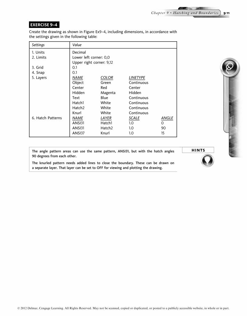
EXERCISE 9–4
Create the drawing as shown in Figure Ex9–4, including dimensions, in accordance withthe settings given in the following table:
Settings Value
1. Units Decimal2. Limits Lower left corner: 0,0
Upper right corner: 9,123. Grid 0.14. Snap 0.15. Layers NAME COLOR LINETYPE
Object Green ContinuousCenter Red CenterHidden Magenta HiddenText Blue ContinuousHatch1 White ContinuousHatch2 White ContinuousKnurl White Continuous
6. Hatch Patterns NAME LAYER SCALE ANGLEANSI31 Hatch1 1.0 0ANSI31 Hatch2 1.0 90ANSI37 Knurl 1.0 15
HINTSThe angle pattern areas can use the same pattern, ANSI31, but with the hatch angles90 degrees from each other.
The knurled pattern needs added lines to close the boundary. These can be drawn ona separate layer. That layer can be set to OFF for viewing and plotting the drawing.
© 2012 Delmar, Cengage Learning. All Rights Reserved. May not be scanned, copied or duplicated, or posted to a publicly accessible website, in whole or in part.
Chap t e r 9 • Hat c h i n g and Bounda r i e s 9-11
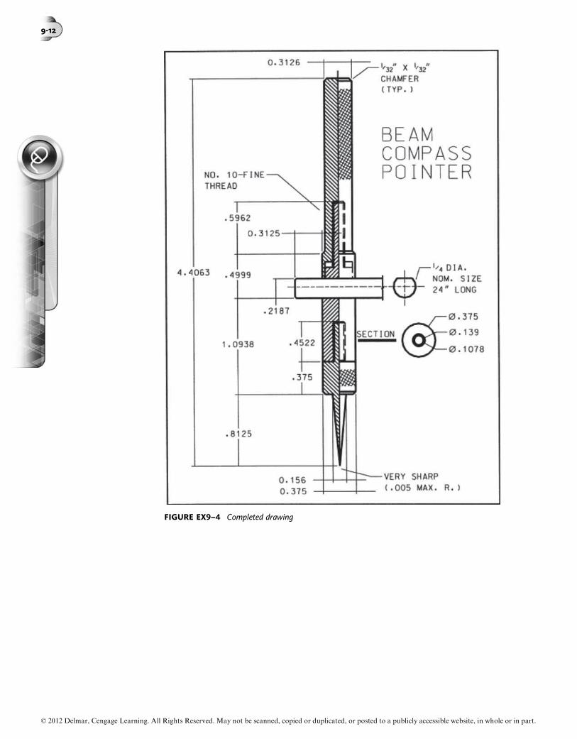
FIGURE EX9–4 Completed drawing
© 2012 Delmar, Cengage Learning. All Rights Reserved. May not be scanned, copied or duplicated, or posted to a publicly accessible website, in whole or in part.
9-12

EXERCISE 9–5
Create the drawing shown in Figure Ex9–5, including dimensions, in accordance with thesettings given in the following table:
Settings Value
1. Units Decimal2. Limits Lower left corner: 0,0
Upper right corner: 17,113. Grid 0.54. Snap 0.255. Layers NAME COLOR LINETYPE
Object Green ContinuousCenter Red CenterHidden Magenta HiddenText Blue ContinuousHatch1 White Continuous
6. Hatch Pattern NAME LAYER SCALE ANGLEANSI31 Hatch 1.0 0
FIGURE EX9–5 Completed drawing
© 2012 Delmar, Cengage Learning. All Rights Reserved. May not be scanned, copied or duplicated, or posted to a publicly accessible website, in whole or in part.
Chap t e r 9 • Hat c h i n g and Bounda r i e s 9-13

EXERCISE 9–6
Create the drawing shown in Figure Ex9–6a, including dimensions, in accordance withthe settings given in the following table:
Settings Value
1. Units Architectural2. Limits Lower left corner: 0,0
Upper right corner: 48 0,32 0
3. Grid 6 00
4. Snap 12 00
5. Layers NAME COLOR LINETYPEBorder Cyan ContinuousObject White ContinuousText Blue ContinuousBrick White ContinuousRoof White Continuous
6. Hatch Patterns NAME LAYER SCALE ANGLEBRICK Brick 16 00 0AR-RSHKE Roof ½ 00 0
HINT Using the dimensions in Figure Ex9–6b, draw the front elevation of the house. The mainconcern about being able to draw hatch patterns within the proper boundaries is to makesure the boundaries are closed. Overlapping at the intersections of the segments thatmake up the boundary is acceptable. But AutoCAD will not complete the hatch pattern ifthere is a gap between any of the boundary segments.
FIGURE EX9–6a Completed drawing
© 2012 Delmar, Cengage Learning. All Rights Reserved. May not be scanned, copied or duplicated, or posted to a publicly accessible website, in whole or in part.
9-14

FIGURE EX9–6b Completed drawing with dimensions
© 2012 Delmar, Cengage Learning. All Rights Reserved. May not be scanned, copied or duplicated, or posted to a publicly accessible website, in whole or in part.
Chap t e r 9 • Hat c h i n g and Bounda r i e s 9-15

EXERCISE 9–7
Open the masonry wall and footing section view drawing that was drawn in Exercise 2–21and add the hatch patterns (see Figure Ex9–7) to the given specifications:
Settings Value
1. Hatch Pattern NAME LAYER SCALE ANGLEAR-CONC FtgHatch 0 0-0½ 00 0ANS137 CMUHatch 0 0-1 00 0ANS137 BbmHatch 0 0-1 00 0
FIGURE EX9–7 Masonry wall and footing section view
© 2012 Delmar, Cengage Learning. All Rights Reserved. May not be scanned, copied or duplicated, or posted to a publicly accessible website, in whole or in part.
9-16

EXERCISE 9–8
Open the prefabricated walk-in refrigerator design that was drawn in Exercise 3–9 andadd the hatch pattern as shown in Figure Ex9–8.
FIGURE EX9–8 Prefabricated walk-in refrigerator
© 2012 Delmar, Cengage Learning. All Rights Reserved. May not be scanned, copied or duplicated, or posted to a publicly accessible website, in whole or in part.
Chap t e r 9 • Hat c h i n g and Bounda r i e s 9-17

EXERCISE 9–9
Open the drawing of the recessed store front (plan and elevation views) that wasdrawn in Exercise 7–10 and add the hatch patterns (see Figure Ex9–9) to the givenspecifications:
Settings Value
1. Hatch Pattern NAME LAYER SCALE ANGLEANSI37 Hatchplan 0 0-3 00 0Brick Hatchelev 0 0-3 00 0ANSI34 Hatchglass 0 0-4 00 70
FIGURE EX9–9 Recessed store front
© 2012 Delmar, Cengage Learning. All Rights Reserved. May not be scanned, copied or duplicated, or posted to a publicly accessible website, in whole or in part.
9-18

EXERCISE 9–10
Create the drawing of wood grain pattern for 6 00� 6 00 parquet floor tiles according to thesettings given in the following table and then add the hatch patterns:
Settings Value
1. Units Architectural2. Limits Lower left corner: 0,0
Upper right corner: 11 0,9 0
3. Grid .125 00
4. Snap .0625 00
5. Layers NAME COLOR LINETYPEBorder White ContinuousTile White ContinuousHatch White ContinuousDimensions White Continuous
© 2012 Delmar, Cengage Learning. All Rights Reserved. May not be scanned, copied or duplicated, or posted to a publicly accessible website, in whole or in part.
Chap t e r 9 • Hat c h i n g and Bounda r i e s 9-19

FIGURE EX9–10 Wood grain pattern
© 2012 Delmar, Cengage Learning. All Rights Reserved. May not be scanned, copied or duplicated, or posted to a publicly accessible website, in whole or in part.
9-20
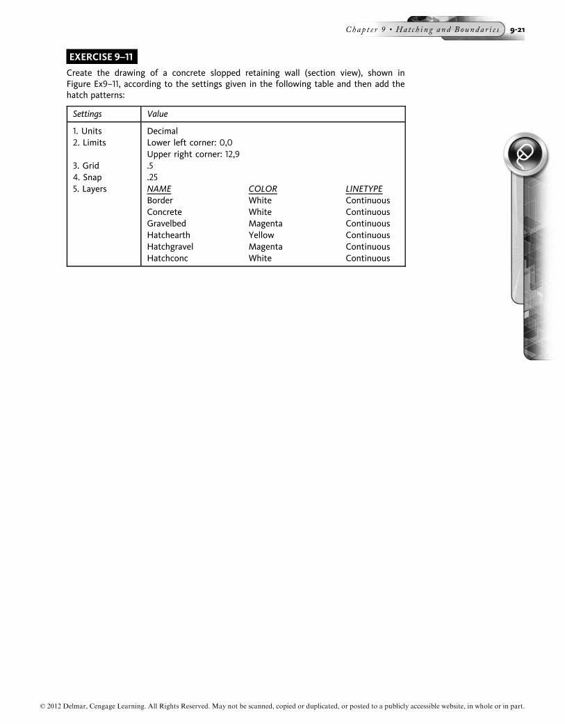
EXERCISE 9–11
Create the drawing of a concrete slopped retaining wall (section view), shown inFigure Ex9–11, according to the settings given in the following table and then add thehatch patterns:
Settings Value
1. Units Decimal2. Limits Lower left corner: 0,0
Upper right corner: 12,93. Grid .54. Snap .255. Layers NAME COLOR LINETYPE
Border White ContinuousConcrete White ContinuousGravelbed Magenta ContinuousHatchearth Yellow ContinuousHatchgravel Magenta ContinuousHatchconc White Continuous
© 2012 Delmar, Cengage Learning. All Rights Reserved. May not be scanned, copied or duplicated, or posted to a publicly accessible website, in whole or in part.
Chap t e r 9 • Hat c h i n g and Bounda r i e s 9-21

FIGURE EX9–11 Slopped retaining wall
© 2012 Delmar, Cengage Learning. All Rights Reserved. May not be scanned, copied or duplicated, or posted to a publicly accessible website, in whole or in part.
9-22

EXERCISE 9–12
Create the drawing of a trench drain shown in Figure Ex9–12 according to the settingsgiven in the following table and then add the hatch patterns:
Settings Value
1. Units Architectural2. Limits Lower left corner: 0,0
Upper right corner: 6 0,4 0
3. Grid .5 00
4. Snap .25 00
5. Layers NAME COLOR LINETYPEBorder White ContinuousConcrete White ContinuousGrating Magenta ContinuousPipe Yellow ContinuousHatchgrate Magenta ContinuousHatchconc White ContinuousHatchpipe Yellow Continuous
6. Hatch Pattern NAME LAYER SCALE ANGLEANS131 Hatchgrate 0 0-01/8 00 45AR-CONC Hatchconc 0 0-1 00 0AR-CONC Hatchpipe 0 0-01/8 00 45
© 2012 Delmar, Cengage Learning. All Rights Reserved. May not be scanned, copied or duplicated, or posted to a publicly accessible website, in whole or in part.
Chap t e r 9 • Hat c h i n g and Bounda r i e s 9-23
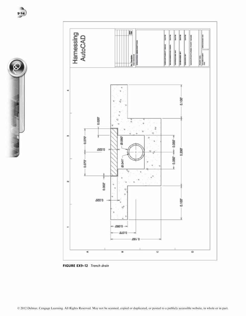
FIGURE EX9–12 Trench drain
© 2012 Delmar, Cengage Learning. All Rights Reserved. May not be scanned, copied or duplicated, or posted to a publicly accessible website, in whole or in part.
9-24

EXERCISE 9–13
Create the drawing of a section through a security retaining wall shown in Figure Ex9–13according to the settings given in the following table and then add the hatch patterns:
Settings Value
1. Units Architectural2. Limits Lower left corner: 0,0
Upper right corner: 20 0,15 0
3. Grid 1 00
4. Snap .5 00
5. Layers NAME COLOR LINETYPEBorder Red ContinuousCenter Green CenterWallfooting Magenta ContinuousReinforcing White HiddenEarth Blue ContinuousRoad Yellow ContinuousGravelbed White ContinuousDimensions White ContinuousHatchearth Blue ContinuousHatchroad Yellow ContinuousHatchGravel White Continuous
© 2012 Delmar, Cengage Learning. All Rights Reserved. May not be scanned, copied or duplicated, or posted to a publicly accessible website, in whole or in part.
Chap t e r 9 • Hat c h i n g and Bounda r i e s 9-25
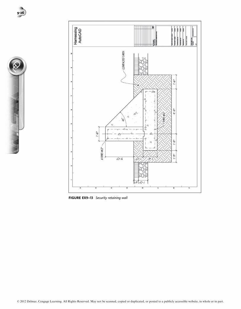
FIGURE EX9–13 Security retaining wall
© 2012 Delmar, Cengage Learning. All Rights Reserved. May not be scanned, copied or duplicated, or posted to a publicly accessible website, in whole or in part.
9-26

EXERCISE 9–14
Create the drawing of a trench drain detail, as shown in Exercise 9–12. Then add thehatch patterns, as shown in Figure Ex9–14:
Settings Value
1. Units Architectural2. Limits Lower left corner: 0,0
Upper right corner: 22 0,17 0
3. Grid 1 00
4. Snap .5 00
5. Layers NAME COLOR LINETYPEBorder White ContinuousCurbs Green ContinuousPaving Red ContinuousReservoir Blue ContinuousDimensions White ContinuousNotes White ContinuousSettingbed White ContinuousDimensions White ContinuousHatchcurbs Green ContinuousHatchpaving Red ContinuousHatchreservoir Blue ContinuousHatchsettingbed White ContinuousHatchearth White Continuous
© 2012 Delmar, Cengage Learning. All Rights Reserved. May not be scanned, copied or duplicated, or posted to a publicly accessible website, in whole or in part.
Chap t e r 9 • Hat c h i n g and Bounda r i e s 9-27

FIGURE EX9–14 Porous paving and stone reservoir detail
© 2012 Delmar, Cengage Learning. All Rights Reserved. May not be scanned, copied or duplicated, or posted to a publicly accessible website, in whole or in part.
9-28

EXERCISE 9–15
Open the drawing of the lighting switch circuit and wiring diagram that was drawn inExercise 4–19 and add the hatch patterns (see Figure Ex9–15) to the given specifications:
Settings Value
1. Hatch Pattern NAME LAYER SCALE ANGLEANS137 Hatch1 0 0-2 00 45ANS131 Hatch2 0 0-2 00 45
FIGURE EX9–15 Lighting switch circuit and wiring diagram
© 2012 Delmar, Cengage Learning. All Rights Reserved. May not be scanned, copied or duplicated, or posted to a publicly accessible website, in whole or in part.
Chap t e r 9 • Hat c h i n g and Bounda r i e s 9-29

EXERCISE 9–16
Open the drawing of the lighting switch circuit and wiring diagram that was drawn inExercise 4–19 and add the hatch patterns (see Figure Ex9–16) to the given specifications:
Settings Value
1. Hatch Pattern NAME LAYER SCALE ANGLEANS137 Hatch1 0 0-2 00 0ANS131 Hatch2 0 0-2 00 0ANS131 Hatch3 0 0-2 00 90
FIGURE EX9–16 Lighting switch circuit and wiring diagram
© 2012 Delmar, Cengage Learning. All Rights Reserved. May not be scanned, copied or duplicated, or posted to a publicly accessible website, in whole or in part.
9-30
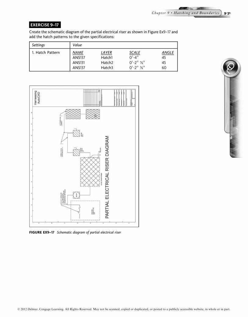
EXERCISE 9–17
Create the schematic diagram of the partial electrical riser as shown in Figure Ex9–17 andadd the hatch patterns to the given specifications:
Settings Value
1. Hatch Pattern NAME LAYER SCALE ANGLEANS137 Hatch1 0 0-4 00 45ANS131 Hatch2 0 0-2 00 ½ 00 45ANS137 Hatch3 0 0-2 00 ½ 00 60
FIGURE EX9–17 Schematic diagram of partial electrical riser
© 2012 Delmar, Cengage Learning. All Rights Reserved. May not be scanned, copied or duplicated, or posted to a publicly accessible website, in whole or in part.
Chap t e r 9 • Hat c h i n g and Bounda r i e s 9-31

EXERCISE 9–18
Open the schematic diagram of the simple Ethernet peer-to-peer network that was drawnin Exercise 5–18. Add the hatch patterns (see Figure Ex9–18) to the given specifications:
Settings Value
1. Hatch Pattern NAME LAYER SCALE ANGLESTARS Hatch1 0 0-2 00 0
FIGURE EX9–18 Schematic diagram of a simple Ethernet peer-to-peer network
© 2012 Delmar, Cengage Learning. All Rights Reserved. May not be scanned, copied or duplicated, or posted to a publicly accessible website, in whole or in part.
9-32
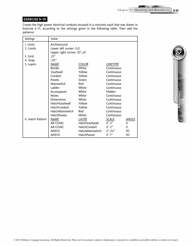
EXERCISE 9–19
Create the high power electrical conduits encased in a concrete vault that was drawn inExercise 6–17, according to the settings given in the following table. Then add thepatterns:
Settings Value
1. Units Architectural2. Limits Lower left corner: 0,0
Upper right corner: 30 0,24 0
3. Grid .25 00
4. Snap .125 00
5. Layers NAME COLOR LINETYPEBorder White ContinuousVaultwall Yellow ContinuousConduit Yellow ContinuousPanels Green ContinuousMainswitch Red ContinuousLadder White ContinuousAccesspanel White HiddenNotes White ContinuousDimensions White ContinuousHatchVaultwall Yellow ContinuousHatchConduit Yellow ContinuousHatchMainswitch Red ContinuousHatchPanels White Continuous
6. Hatch Pattern NAME LAYER SCALE ANGLEAR-CONC HatchVaultwall 0 0-2 00 0AR-CONC HatchConduit 0 0-2 00 0ANS131 HatchMainswitch 0 0-2½ 00 90ANS131 HatchPanels 0 0-1 00 90
© 2012 Delmar, Cengage Learning. All Rights Reserved. May not be scanned, copied or duplicated, or posted to a publicly accessible website, in whole or in part.
Chap t e r 9 • Hat c h i n g and Bounda r i e s 9-33

FIGURE EX9–19 High power electrical conduits encased in a concrete vault
© 2012 Delmar, Cengage Learning. All Rights Reserved. May not be scanned, copied or duplicated, or posted to a publicly accessible website, in whole or in part.
9-34

EXERCISE 9–20
Open the drawing of the steel pipe bracket support that was drawn in Exercise 2–31 andthen add the hatch patterns (see Figure Ex9–20) to the given specifications:
Settings Value
1. Hatch Pattern NAME LAYER SCALE ANGLEANS137 Hatchpipe 0 0-2 00 45ANS137 Hatchwall 0 0-½ 00 45
FIGURE EX9–20 Steel pipe bracket support
© 2012 Delmar, Cengage Learning. All Rights Reserved. May not be scanned, copied or duplicated, or posted to a publicly accessible website, in whole or in part.
Chap t e r 9 • Hat c h i n g and Bounda r i e s 9-35

EXERCISE 9–21
Create the drawing of typical house trap pit detail according to the settings given in thefollowing table and then add the hatch patterns:
Settings Value
1. Units Architectural2. Limits Lower left corner: 0,0
Upper right corner: 8 0,7 0
3. Grid .25 00
4. Snap .125 00
5. Layers NAME COLOR LINETYPEBorder White ContinuousPitwall Yellow ContinuousPipesleeves Blue ContinuousPipes Green ContinuousCenterlines Red CenterNote White ContinuousDimensions White ContinuousHatchsleeve Green ContinuousHatchwall Yellow Continuous
6. Hatch Pattern NAME LAYER SCALE ANGLEANS137 Hatchsleeve 0 0-3/8 00 45AR-CONC Hatchwall 0 0-2 00 0
© 2012 Delmar, Cengage Learning. All Rights Reserved. May not be scanned, copied or duplicated, or posted to a publicly accessible website, in whole or in part.
9-36

FIGURE EX9–21 Typical house trap pit detail
© 2012 Delmar, Cengage Learning. All Rights Reserved. May not be scanned, copied or duplicated, or posted to a publicly accessible website, in whole or in part.
Chap t e r 9 • Hat c h i n g and Bounda r i e s 9-37
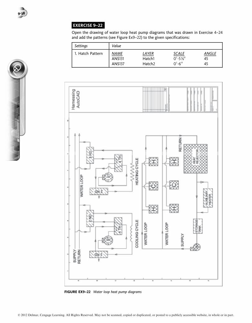
EXERCISE 9–22
Open the drawing of water loop heat pump diagrams that was drawn in Exercise 4–24and add the patterns (see Figure Ex9–22) to the given specifications:
Settings Value
1. Hatch Pattern NAME LAYER SCALE ANGLEANS131 Hatch1 0 0-5½00 45ANS137 Hatch2 0 0-6 00 45
FIGURE EX9–22 Water loop heat pump diagrams
© 2012 Delmar, Cengage Learning. All Rights Reserved. May not be scanned, copied or duplicated, or posted to a publicly accessible website, in whole or in part.
9-38
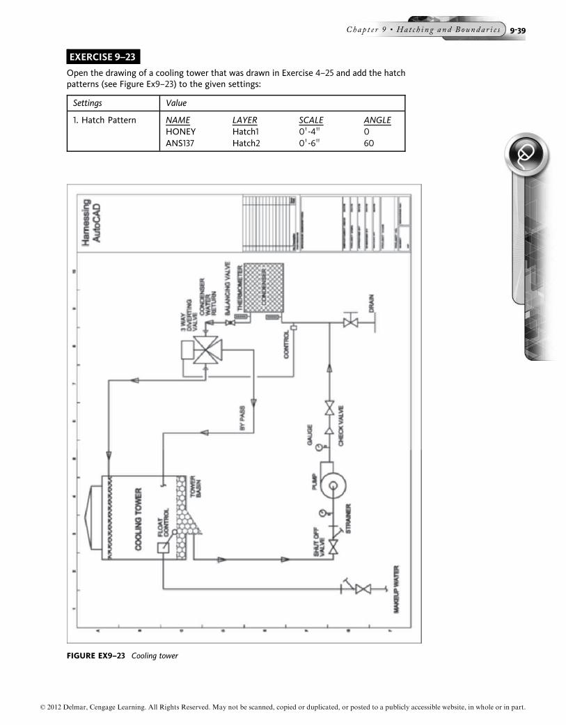
EXERCISE 9–23
Open the drawing of a cooling tower that was drawn in Exercise 4–25 and add the hatchpatterns (see Figure Ex9–23) to the given settings:
Settings Value
1. Hatch Pattern NAME LAYER SCALE ANGLEHONEY Hatch1 0 0-4 00 0ANS137 Hatch2 0 0-6 00 60
FIGURE EX9–23 Cooling tower
© 2012 Delmar, Cengage Learning. All Rights Reserved. May not be scanned, copied or duplicated, or posted to a publicly accessible website, in whole or in part.
Chap t e r 9 • Hat c h i n g and Bounda r i e s 9-39

EXERCISE 9–24
Open the drawing of typical residential building gas service that was drawn in Exercise 5–23and add the hatch patterns (see Figure Ex9–24) to the given settings:
Settings Value
1. Hatch Pattern NAME LAYER SCALE ANGLEANS137 Hatch1 1 00 45ANS137 Hatch2 ½ 00 45ANS137 Hatch3 ¼ 00 45AR-CONC Hatch4 ¼ 00 0
FIGURE EX9–24 Typical residential building gas service
© 2012 Delmar, Cengage Learning. All Rights Reserved. May not be scanned, copied or duplicated, or posted to a publicly accessible website, in whole or in part.
9-40