4ch digital video recorder user’s manual ( v1.1 )
TRANSCRIPT
4CH Digital Video Recorder
User’s Manual ( v1.1 )
Index
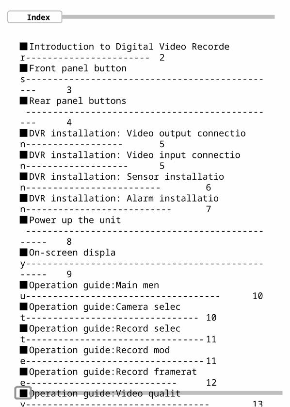
Introduction to Digital Video Recorder----------------------- 2Front panel buttons----------------------------------------------- 3Rear panel buttons ----------------------------------------------- 4DVR installation: Video output connection------------------ 5DVR installation: Video input connection------------------- 5DVR installation: Sensor installation------------------------- 6DVR installation: Alarm installation--------------------------- 7Power up the unit ------------------------------------------------- 8On-screen display------------------------------------------------- 9Operation guide:Main menu------------------------------------ 10Operation guide:Camera select-------------------------------- 10Operation guide:Record select--------------------------------- 11Operation guide:Record mode--------------------------------- 11Operation guide:Record framerate---------------------------- 12Operation guide:Video quality---------------------------------- 13Operation guide:Record schedule-----------------------------14Operation guide:Sub menu-Password change-------------15Operation guide:Sub menu-Time set------------------------- 16Operation guide:Sub menu-Audio record/playback------ 16Operation guide:Sub menu-Display format----------------- 16Operation guide:HDD setup ----------------------------------- 17Operation guide:Sensor setup -------------------------------- 18Operation guide: How to start Motion detection recording ----------------------------------------------------------- 19Operation guide:Networking setup--------------------------- 20Operation guide:Playback -------------------------------------- 21Appendix I Regulatory ------------------------------------------- 22Appendix II Networking ----------------------------------------- 23
1
Introduction to Digital Video Recorder (DVR) The digital video recorder (DVR) is for recording/retrieving video streams from up to 4 channels at the same time. It adopts a digital image compression technology to compress the input channel video streams, and uses HDD to record the compressed video stream.
The following operation guide explains how to operate/manage the DVR, and the following installation guide explains how to install DVR at your home or HDD into the DVR.
Hope you enjoy it, use it to protect your home, and eventually make your home as SAFE HOME.
Introduction
2
3 4
118 9 10
151413
12
21 567
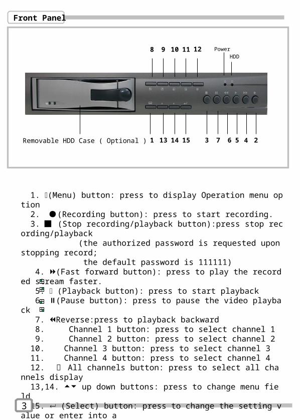
1. (Menu) button: press to display Operation menu option 2. (Recording button): press to start recording. 3. (Stop recording/playback button):press stop recording/playback (the authorized password is requested upon stopping record; the default password is 111111) 4. (Fast forward button): press to play the recorded stream faster. 5. (Playback button): press to start playback 6. (Pause button): press to pause the video playback 7. Reverse:press to playback backward 8. Channel 1 button: press to select channel 1 9. Channel 2 button: press to select channel 2 10. Channel 3 button: press to select channel 3 11. Channel 4 button: press to select channel 4 12. 田 All channels button: press to select all channels display 13,14. up down buttons: press to change menu field 15. (Select) button: press to change the setting value or enter into a sub menu
Front Panel
3
Power
HDD
Removable HDD Case ( Optional )
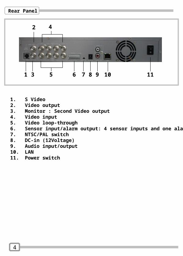
1. S Video 2. Video output 3. Monitor : Second Video output 4. Video input 5. Video loop-through6. Sensor input/alarm output: 4 sensor inputs and one alarm output7. NTSC/PAL switch 8. DC-in (12Voltage)9. Audio input/output10. LAN11. Power switch
Rear Panel
4
2
1 3 5 6 7 8
4
9 10 11
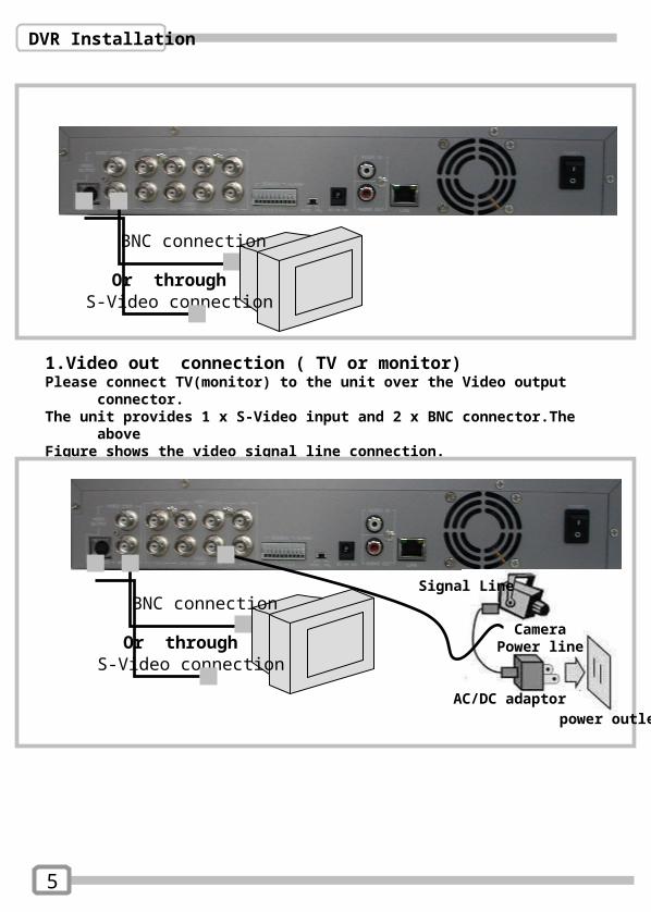
1.Video out connection ( TV or monitor)Please connect TV(monitor) to the unit over the Video output connector. The unit provides 1 x S-Video input and 2 x BNC connector.The above Figure shows the video signal line connection.
DVR Installation
5
BNC connection
S-Video connectionOr through
BNC connection
S-Video connectionOr through
AC/DC adaptor power outlet
Camera
Signal Line
Power line

2. Video Input connection ( Camera)Please connect Camera to the unit over the Video input connector. The unit provides 4 x BNC connectors.The camera installation Procedures are as following: i. Connect the video signal line: connect the video signal line to the unitii.Connect camera power line: Connect camera’s adaptor to camera, and plug in the adaptor. The complete connection with a camera will be shown as figure below
DVR Installation
3.Sensor InstallationThe unit provides 4 sensor input for 4 channels. The sensor Installation procedures are as follows. There are two simple steps For the installation of the sensors.i. Connect the sensor signal line: Connect the video signal line to the unit. The Sensor signal terminal is at the unit’s back panelii.Connect the sensor adaptor jack into the sensor, and plug in the adaptor.
CH1 CH2 CH3 CH4 Alarm out
6
power outletAC/DC adaptor
Sensor
Power line
Signal Line
DVR Installation
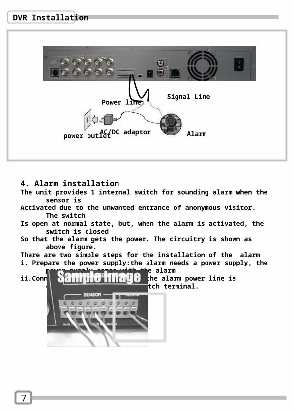
4. Alarm installationThe unit provides 1 internal switch for sounding alarm when the sensor is Activated due to the unwanted entrance of anonymous visitor. The switch Is open at normal state, but, when the alarm is activated, the switch is closed So that the alarm gets the power. The circuitry is shown as above figure. There are two simple steps for the installation of the alarmi. Prepare the power supply:the alarm needs a power supply, the power supply
comes with the alarm ii.Connect the alarm power line:the alarm power line is connected to the alarm
switch terminal.
AlarmAC/DC adaptor power outlet
Signal LinePower line
7
Turn off and on the DVR!
HDD CHECKING OK
Power up the unit
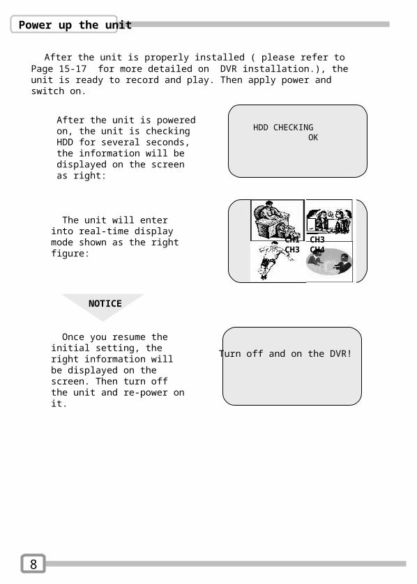
After the unit is properly installed ( please refer to Page 15-17 for more detailed on DVR installation.), the unit is ready to record and play. Then apply power and switch on.
After the unit is powered on, the unit is checking HDD for several seconds, the information will be displayed on the screen as right:
CH1 CH3CH3 CH4
The unit will enter into real-time display mode shown as the right figure:
NOTICE
Once you resume the initial setting, the right information will be displayed on the screen. Then turn off the unit and re-power on it.
8
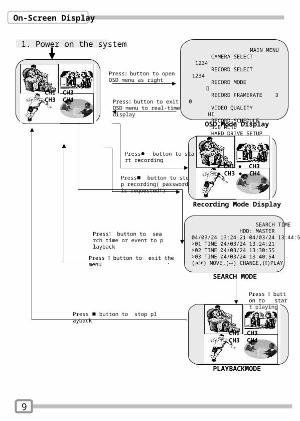
SEARCH TIME HDD: MASTER04/03/24 13:24:21-04/03/24 13:44:54>01 TIME 04/03/24 13:24:21>02 TIME 04/03/24 13:30:55>03 TIME 04/03/24 13:40:54() MOVE,() CHANGE,()PLAY
MAIN MENU CAMERA SELECT 1234 RECORD SELECT 1234 RECORD MODE 田 RECORD FRAMERATE 30 VIDEO QUALITY HI RECORD SCHEDULE SUB MENU HARD DRIVE SETUP SENSOR SETUP NETWORK SETUP
Press button to open OSD menu as right
On-Screen Display
1. Power on the system
CH1 CH3CH3 CH4
● CH1 ● CH3● CH3 ● CH4
Press button to exit OSD menu to real-time display
Press button to start recording
Recording Mode Display
OSD Mode Display
SEARCH MODE
CH1 CH3CH3 CH4
PLAYBACKMODE
Press button to search time or event to playback
Press button to stop recording( password is requested!)
Press button to exit the menu
Press button to stop playback
Press button to start playing
9
Operation guide
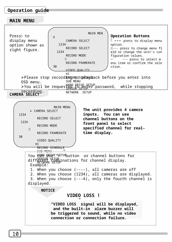
MAIN MENU CAMERA SELECT 1234 RECORD SELECT 1234 RECORD MODE 田 RECORD FRAMERATE 30 VIDEO QUALITY HI RECORD SCHEDULE SUB MENU HARD DRIVE SETUP SENSOR SETUP NETWORK SETUP
Operation Buttons --- press to display menu option.--- press to change menu field or change the unit’s configuration values. --- press to select menu item or confirm the selection.
Press to display menu option shown as right figure.
MAIN MENU
CAMERA SELECT
Please stop recording or playback before you enter into OSD menu.You will be requested to enter password, while stopping recording.
The unit provides 4 camera inputs. You can use channel buttons on the front panel to select specified channel for real-time display.
MAIN MENU CAMERA SELECT 1234 RECORD SELECT 1234 RECORD MODE 田 RECORD FRAMERATE 30 VIDEO QUALITY HI RECORD SCHEDULE SUB MENU HARD DRIVE SETUP SENSOR SETUP NETWORK SETUP
You can use “” button or channel buttons for different combinations for channel display. Example: 1. When you choose (----), all cameras are off 2. When you choose (1234), all cameras are displayed. 3. When you choose (---4), only the fourth channel is displayed.
NOTICEVIDEO LOSS !
“VIDEO LOSS” signal will be displayed, and the built-in alarm buzzer will be triggered to sound, while no video connection or connection failure.
10
Operation guide
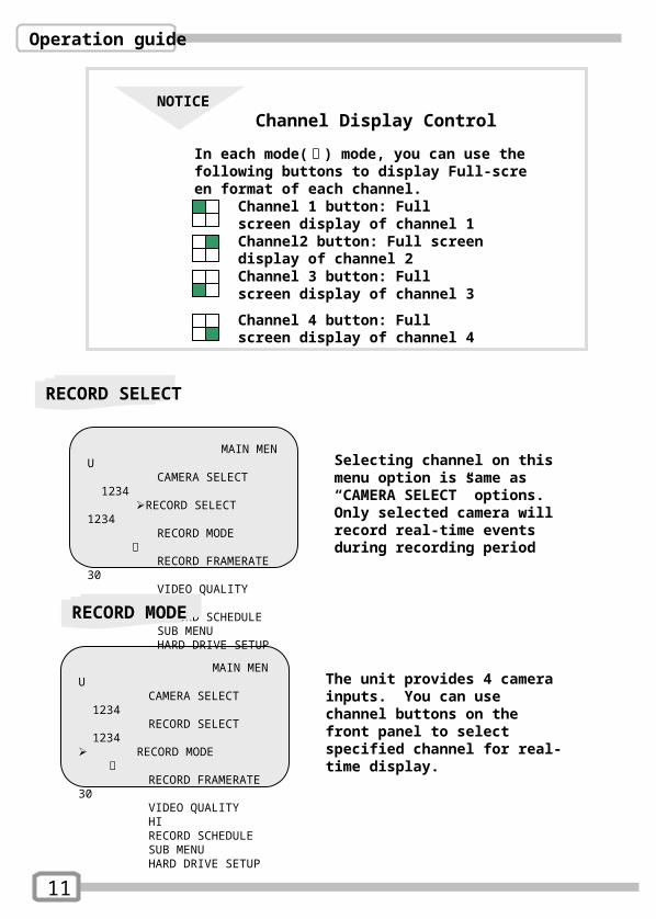
The unit provides 4 camera inputs. You can use channel buttons on the front panel to select specified channel for real-time display.
MAIN MENU CAMERA SELECT 1234 RECORD SELECT 1234 RECORD MODE 田 RECORD FRAMERATE 30 VIDEO QUALITY HI RECORD SCHEDULE SUB MENU HARD DRIVE SETUP
RECORD SELECT
MAIN MENU CAMERA SELECT 1234 RECORD SELECT 1234 RECORD MODE 田 RECORD FRAMERATE 30 VIDEO QUALITY HI RECORD SCHEDULE SUB MENU HARD DRIVE SETUP
Selecting channel on this menu option is same as “CAMERA SELECT” options.Only selected camera will record real-time events during recording period
NOTICEChannel Display Control
In each mode( 回 ) mode, you can use the following buttons to display Full-screen format of each channel.
Channel 1 button: Full screen display of channel 1Channel2 button: Full screen display of channel 2
Channel 4 button: Full screen display of channel 4
Channel 3 button: Full screen display of channel 3
RECORD MODE
11
Operation guide
RECORD FRAMRATE
MAIN MENU CAMERA SELECT 1234 RECORD SELECT 1234 RECORD MODE 田 RECORD FRAMERATE 30 VIDEO QUALITY HI RECORD SCHEDULE SUB MENU HARD DRIVE SETUP
MAIN MENU CAMERA SELECT 1234 RECORD SELECT 1234 RECORD MODE 田 RECORD FRAMERATE 30 VIDEO QUALITY HI RECORD SCHEDULE SUB MENU HARD DRIVE SETUP
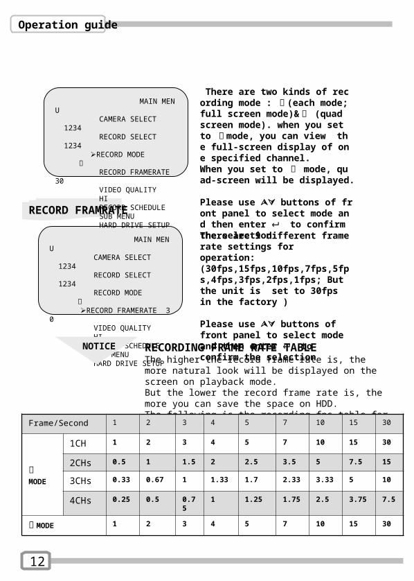
There are two kinds of recording mode : 回 (each mode; full screen mode)& 田 (quad screen mode). when you set to 回 mode, you can view the full-screen display of one specified channel.When you set to 田 mode, quad-screen will be displayed. Please use buttons of front panel to select mode and then enter to confirm the selection
There are 9 different frame rate settings for operation: (30fps,15fps,10fps,7fps,5fps,4fps,3fps,2fps,1fps; But the unit is set to 30fps in the factory )
Please use buttons of front panel to select mode and then enter to confirm the selection
NOTICE RECORDING FRAME RATE TABLEThe higher the record frame rate is, the more natural look will be displayed on the screen on playback mode. But the lower the record frame rate is, the more you can save the space on HDD.The following is the recording fps table for your reference
Frame/Second 1 2 3 4 5 7 10 15 30
回MODE
1CH 1 2 3 4 5 7 10 15 30
2CHs 0.5 1 1.5 2 2.5 3.5 5 7.5 15
3CHs 0.33 0.67 1 1.33 1.7 2.33 3.33 5 10
4CHs 0.25 0.5 0.75 1 1.25 1.75 2.5 3.75 7.5
田 MODE 1 2 3 4 5 7 10 15 30
12
Operation guide
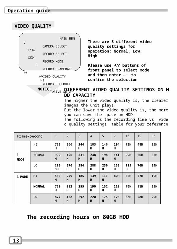
VIDEO QUALITY
MAIN MENU CAMERA SELECT 1234 RECORD SELECT 1234 RECORD MODE 田 RECORD FRAMERATE 30 VIDEO QUALITY HI RECORD SCHEDULE SUB MENU HARD DRIVE SETUP
There are 3 different video quality settings for operation: Normal, Low, High
Please use buttons of front panel to select mode and then enter to confirm the selection
NOTICE DIFFERENT VIDEO QUALITY SETTINGS ON HDD CAPACITYThe higher the video quality is, the clearer images the unit plays. But the lower the video quality is, the more you can save the space on HDD.The following is the recording time vs video quality settings table for your reference
Frame/Second 1 2 3 4 5 7 10 15 30
回MODE
HI 733H
366H
244H
183H
146H
104H
73H 48H 25H
NORMAL 992H
496H
331H
248H
198H
141H
99H 66H 33H
LO 1153H
576H
384H
288H
230H
153H
115H
76H 39H
田MODE
HI 556H
279H
185H
139H
111H
80H 56H 37H 19H
NORMAL 763H
382H
255H
190H
152H
110H
76H 51H 25H
LO 877H
438H
292H
220H
175H
125H
88H 58H 29H
13
The recording hours on 80GB HDD
Operation guide
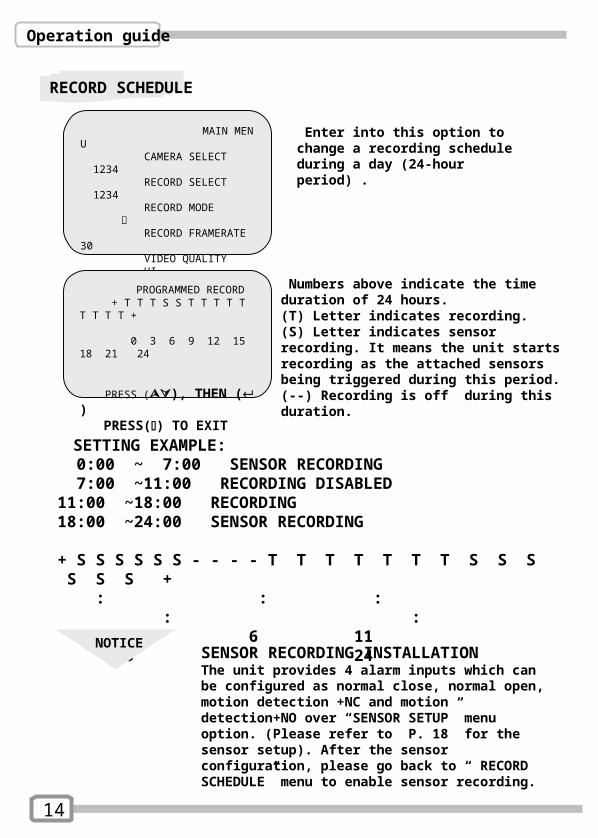
RECORD SCHEDULE
MAIN MENU CAMERA SELECT 1234 RECORD SELECT 1234 RECORD MODE 田 RECORD FRAMERATE 30 VIDEO QUALITY HI RECORD SCHEDULE SUB MENU HARD DRIVE SETUP SENSOR SETUP
Enter into this option to change a recording schedule during a day (24-hour period) .
PROGRAMMED RECORD + T T T S S T T T T T T T T T +
0 3 6 9 12 15 18 21 24
PRESS (), THEN ( ) PRESS() TO EXIT
Numbers above indicate the time duration of 24 hours. (T) Letter indicates recording.(S) Letter indicates sensor recording. It means the unit starts recording as the attached sensors being triggered during this period.(--) Recording is off during this duration.
SETTING EXAMPLE: 0:00 ~ 7:00 SENSOR RECORDING 7:00 ~11:00 RECORDING DISABLED 11:00 ~18:00 RECORDING 18:00 ~24:00 SENSOR RECORDING
+ S S S S S S - - - - T T T T T T T S S S S S S + : : : : : 0 6 11 18 24
NOTICESENSOR RECORDING INSTALLATIONThe unit provides 4 alarm inputs which can be configured as normal close, normal open, motion detection +NC and motion detection+NO over “SENSOR SETUP” menu option. (Please refer to P. 18 for the sensor setup). After the sensor configuration, please go back to “ RECORD SCHEDULE” menu to enable sensor recording.
14
Operation guide
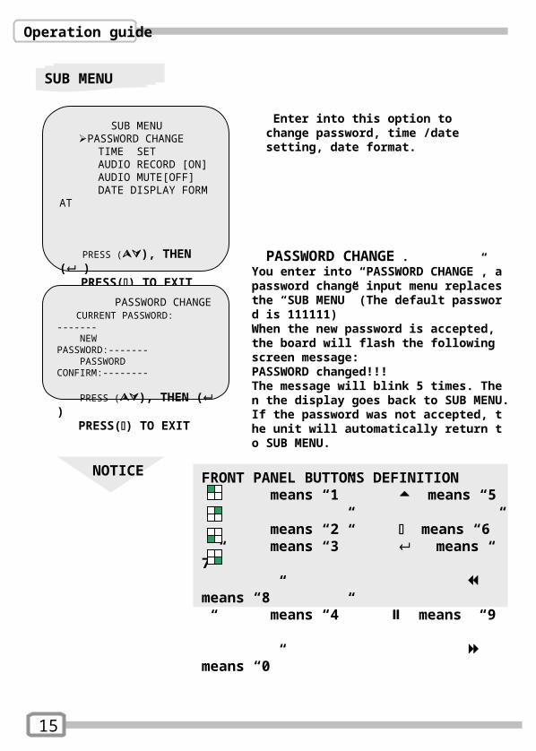
SUB MENU
Enter into this option to change password, time /date setting, date format.
SUB MENU PASSWORD CHANGE TIME SET AUDIO RECORD [ON] AUDIO MUTE[OFF] DATE DISPLAY FORMAT
PRESS (), THEN ( ) PRESS() TO EXIT PASSWORD CHANGE .
You enter into “PASSWORD CHANGE”, a password change input menu replaces the “SUB MENU” (The default password is 111111) When the new password is accepted, the board will flash the following screen message:PASSWORD changed!!!The message will blink 5 times. Then the display goes back to SUB MENU.If the password was not accepted, the unit will automatically return to SUB MENU.
NOTICE FRONT PANEL BUTTONS DEFINITION means “1” means “5” means “2” means “6” means “3” means “7” means “8” means “4” means “9” means “0”
PASSWORD CHANGE CURRENT PASSWORD: ------- NEW PASSWORD:------- PASSWORD CONFIRM:--------
PRESS (), THEN ( ) PRESS() TO EXIT
15
Operation guide
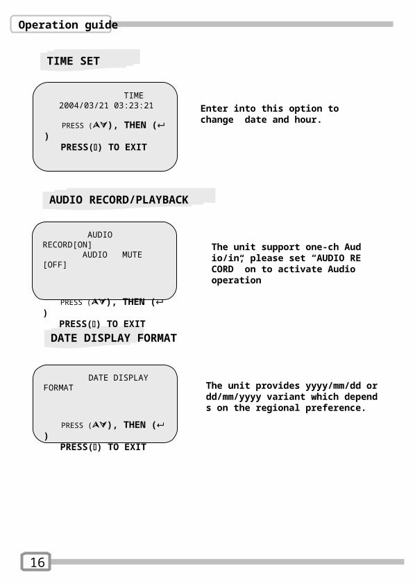
TIME SET
Enter into this option to change date and hour.
TIME 2004/03/21 03:23:21
PRESS (), THEN ( ) PRESS() TO EXIT
DATE DISPLAY FORMAT
PRESS (), THEN ( ) PRESS() TO EXIT
DATE DISPLAY FORMAT
The unit provides yyyy/mm/dd or dd/mm/yyyy variant which depends on the regional preference.
16
AUDIO RECORD[ON] AUDIO MUTE [OFF]
PRESS (), THEN ( ) PRESS() TO EXIT
The unit support one-ch Audio/in, please set “AUDIO RECORD” on to activate Audio operation
AUDIO RECORD/PLAYBACK

Operation guide
HDD SETUP
OVERWRITE ENABLED:If you choose “YES”, the unit will
continue recording and overwrite the recorded data when HDD’s space is full
If you choose “NO”, the unit will stop recording while HDD’s space is full
MASTER HDD SIZE:It indicates the capacity of the primary
HDD installed in the unitMASTER HDD USED:It indicates how percentage of HDD’s
capacity has been occupied.
MASTER HDD FORMAT:It erases all of the recorded data in
Master HDD The authorized password is requested
before formatting, after the unit formatted, the following information will appear on the screen “HARD DISK FORMATTED” .
HARD DRIVE SETUPOVERWRITE ENABLED YESMASTER HDD SIZE 40000MB MASTER HDD USED 0MB 0%MASTER HDD FORMAT SLAVE HDD SIZE SLAVE HDD USEDSLAVE HDD FORMAT
PRESS (), THEN ( ) PRESS() TO EXIT
17
Operation guide
SENSOR SETUP
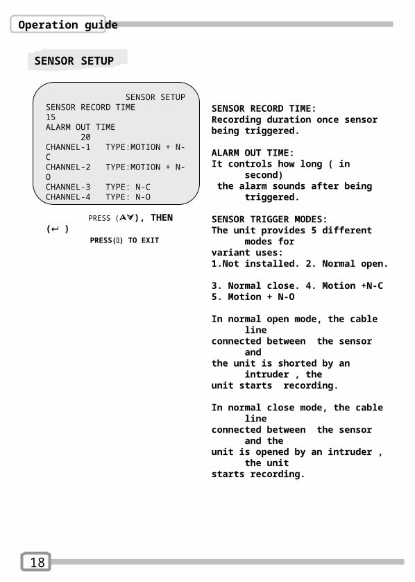
SENSOR RECORD TIME: Recording duration once sensor being triggered.
ALARM OUT TIME:It controls how long ( in second) the alarm sounds after being triggered.
SENSOR TRIGGER MODES:The unit provides 5 different modes for variant uses: 1.Not installed. 2. Normal open. 3. Normal close. 4. Motion +N-C5. Motion + N-O
In normal open mode, the cable line connected between the sensor and the unit is shorted by an intruder , theunit starts recording.
In normal close mode, the cable line connected between the sensor and the unit is opened by an intruder , the unitstarts recording.
SENSOR SETUPSENSOR RECORD TIME 15ALARM OUT TIME 20CHANNEL-1 TYPE:MOTION + N-C CHANNEL-2 TYPE:MOTION + N-OCHANNEL-3 TYPE: N-CCHANNEL-4 TYPE: N-O
PRESS (), THEN ( ) PRESS() TO EXIT
18
Operation guide
How to operate Motion detection recording
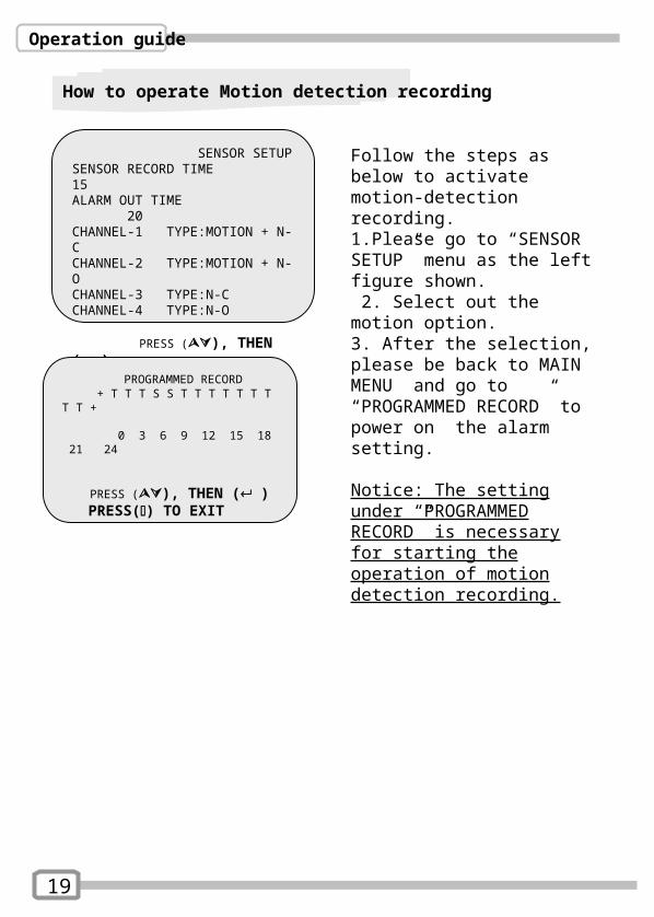
SENSOR SETUPSENSOR RECORD TIME 15ALARM OUT TIME 20CHANNEL-1 TYPE:MOTION + N-C CHANNEL-2 TYPE:MOTION + N-OCHANNEL-3 TYPE:N-CCHANNEL-4 TYPE:N-O
PRESS (), THEN ( ) PRESS() TO EXIT
19
PROGRAMMED RECORD + T T T S S T T T T T T T T T +
0 3 6 9 12 15 18 21 24
PRESS (), THEN ( ) PRESS() TO EXIT
Follow the steps as below to activate motion-detection recording.1.Please go to “SENSOR SETUP” menu as the left figure shown. 2. Select out the motion option.3. After the selection, please be back to MAIN MENU and go to “PROGRAMMED RECORD” to power on the alarm setting.
Notice: The setting under “PROGRAMMED RECORD” is necessary for starting the operation of motion detection recording.
Operation guide
NETWORK SETUP
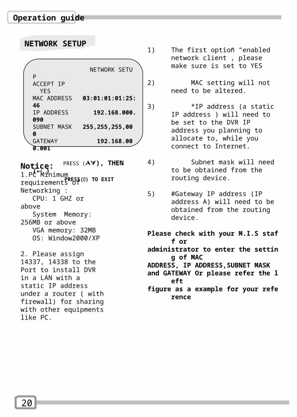
NETWORK SETUPACCEPT IP YESMAC ADDRESS 03:01:01:01:25:46 IP ADDRESS 192.168.000.090SUBNET MASK 255,255,255,000GATEWAY 192.168.000.001
PRESS (), THEN ( ) PRESS() TO EXIT
20
Notice: 1.PC Minimum requirements of Networking : CPU: 1 GHZ or above System Memory: 256MB or above VGA memory: 32MB OS: Window2000/XP
2. Please assign 14337, 14338 to the Port to install DVR in a LAN with a static IP address under a router ( with firewall) for sharing with other equipments like PC.
1) The first option “enabled network client”, please make sure is set to YES
2) MAC setting will not need to be altered.
3) *IP address (a static IP address ) will need to be set to the DVR IP address you planning to allocate to, while you connect to Internet.
4) Subnet mask will need to be obtained from the routing device.
5) #Gateway IP address (IP address A) will need to be obtained from the routing device.
Please check with your M.I.S staff or administrator to enter the setting of MAC ADDRESS, IP ADDRESS,SUBNET MASK and GATEWAY Or please refer the left figure as a example for your reference
Operation guide
PLAYBACK
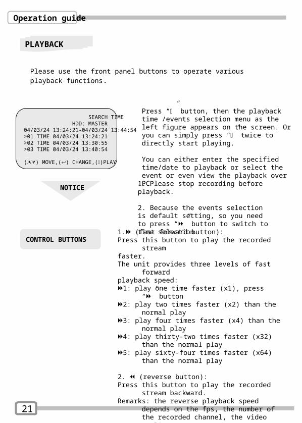
SEARCH TIME HDD: MASTER04/03/24 13:24:21-04/03/24 13:44:54>01 TIME 04/03/24 13:24:21>02 TIME 04/03/24 13:30:55>03 TIME 04/03/24 13:40:54
() MOVE,() CHANGE,()PLAY
Please use the front panel buttons to operate various playback functions.
Press “” button, then the playback time /events selection menu as the left figure appears on the screen. Or you can simply press “” twice to directly start playing. You can either enter the specified time/date to playback or select the event or even view the playback over PC
NOTICE
1. Please stop recording before playback.
2. Because the events selection is default setting, so you need to press “” button to switch to time selection.
CONTROL BUTTONS
1. (fast forward button): Press this button to play the recorded stream faster.The unit provides three levels of fast forward playback speed: 1: play one time faster (x1), press “” button2: play two times faster (x2) than the normal play3: play four times faster (x4) than the normal play4: play thirty-two times faster (x32) than the normal
play5: play sixty-four times faster (x64) than the normal
play
2. (reverse button): Press this button to play the recorded stream
backward. Remarks: the reverse playback speed depends on the
fps, the number of the recorded channel, the video quality.
3. (pause button) :Press this button to pause the playback, or to advance
one single frame upon pause mode.
21
Appendix I.
Regulatory
FCC Certification This equipment has been tested and found to comply with the limits for a class A digital device, pursuant to Part 15 of the FCC rules. These limits are designed to provide reasonable protection against harmful interference when the equipment is operated in a commercial environment. This equipment generates, uses, and can radiate radio frequency energy and, if not installed and used in accordance with the instruction manual, may cause harmful interference to radio communications. Operation of this equipment in a residential area is likely to cause harmful interference in which case the user will be required to correct the interference a the own expense.
CE MarkThis product is marked with the CE symbol and indicates compliance with all applicable directives.
22
Appendix II.
Networking
23
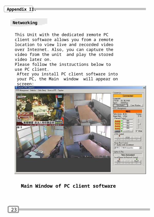
This Unit with the dedicated remote PC client software allows you from a remote location to view live and recorded video over Internet. Also, you can capture the video from the unit and play the stored video later on. Please follow the instructions below to use PC client.
After you install PC client software into your PC, the Main window will appear on screen:
Main Window of PC client software
Appendix II.
Networking
24
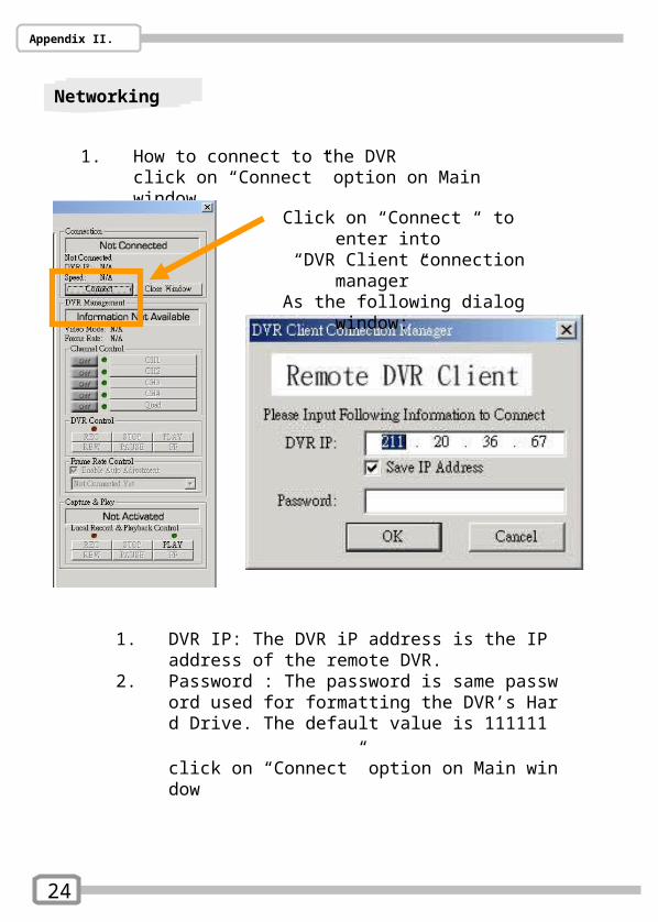
1. How to connect to the DVRclick on “Connect” option on Main window
Click on “Connect “ to enter into “DVR Client connection manager” As the following dialog window:
1. DVR IP: The DVR iP address is the IP address of the remote DVR.
2. Password : The password is same password used for formatting the DVR’s Hard Drive. The default value is 111111
click on “Connect” option on Main window
Appendix II.
Networking
25
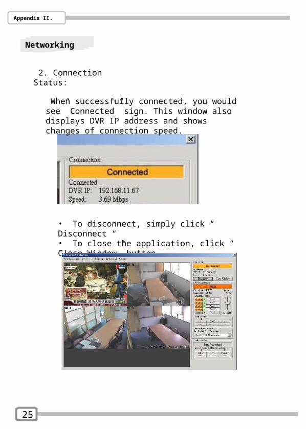
2. Connection Status:
When successfully connected, you would see” Connected” sign. This window also displays DVR IP address and shows changes of connection speed.
• To disconnect, simply click “ Disconnect “ • To close the application, click “ Close Window” button

Appendix II.
Networking
26
3. DVR control
The panel shown as the following figure operates exactly as the remote DVR operational button allow you to control remote DVR to live view, record and playback as well.
Appendix II.
Networking
27
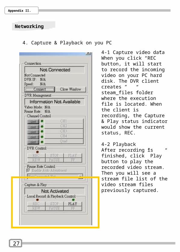
4. Capture & Playback on you PC
4-1 Capture video dataWhen you click “REC” button, it will start to record the incoming video on your PC hard disk. The DVR client creates “ steam_files”folder where the execution file is located. When the client is recording, the Capture & Play status indicator would show the current status, REC.
4-2 PlaybackAfter recording is finished, click” Play” button to play the recorded video stream. Then you will see a stream file list of the video stream files previously captured.
Appendix II.
Networking
28
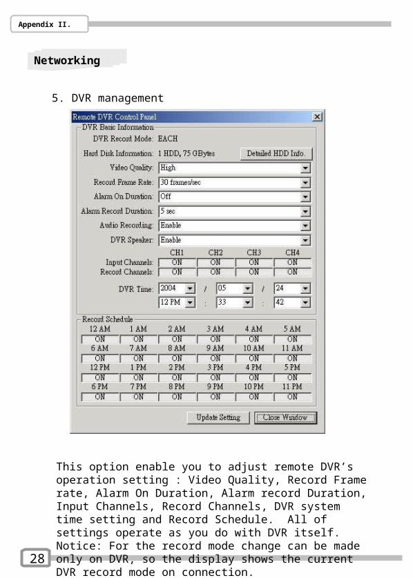
5. DVR management
This option enable you to adjust remote DVR’s operation setting : Video Quality, Record Frame rate, Alarm On Duration, Alarm record Duration, Input Channels, Record Channels, DVR system time setting and Record Schedule. All of settings operate as you do with DVR itself. Notice: For the record mode change can be made only on DVR, so the display shows the current DVR record mode on connection.
Appendix II.
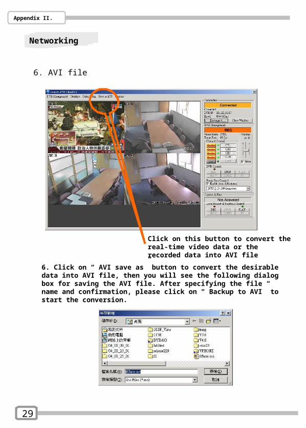
Click on this button to convert the real-time video data or the recorded data into AVI file
6. Click on “ AVI save as” button to convert the desirable data into AVI file, then you will see the following dialog box for saving the AVI file. After specifying the file name and confirmation, please click on “ Backup to AVI” to start the conversion.
29
Networking
6. AVI file