4d printing method based on the composites with embedded...
TRANSCRIPT

4D printing method based on the composites with embedded continuous
fibers Qingrui Wang, Xiaoyong Tian, Lan Huang
State Key Laboratory for Manufacturing Systems Engineering
Xi’an Jiaotong University
Xi’an, Shaanxi, 710049, China
Abstract
Most of the current 4D printing technologies have the following
defects: 1) the deformation shape is simple; 2) the deforming precision is
poor; 3) the deformation process is always uncontinuous. In this study, a
new 4D printing process based on the composites with embedded
continuous fibers is proposed. In this process, a bilayer structure
consisting of the top layer of continuous fibers and the bottom layer with
resin is 3D printed. Due to the different thermal expansion coefficient and
elastic modulus of the top and bottom layers, the structure will produce
bending deformation when the temperature changes. It is found that the
curvature value and the curvature direction of the composite structure can
be precisely controlled by the angle of the intersecting fibers. The
influence of fiber trajectory on curvature is studied, and then, the
controllable deformation of any developable surface is achieved.
1073
Solid Freeform Fabrication 2018: Proceedings of the 29th Annual InternationalSolid Freeform Fabrication Symposium – An Additive Manufacturing Conference

Keywords: 4D printing, continuous fiber, composites, programmable
morphing
1. Introduction
4D printing is an additive manufacturing technology based on the
development of 3D printing. 4D printed material can produce controllable
deformation, and the factors that stimulate this deformation can be
temperature, humidity and so on.[1] At present, there are three main
methods for 4D printing. Shape memory materials are used as materials
for 4D printing because they can change from temporary shapes to final
shapes at the transition temperature.[2-4] However, this deformation is
often discontinuous. Inspired by the deformation of pine cones and wheat
awn, a new 4D printing method has been put forward.[5, 6] The rigid
granular materials, such as cellulose fibers, are embedded in a flexible
matrix, such as hydrogels. Because the rigid materials are inhomogeneous,
the material will bend when it is placed in the water. However, this
material can only achieve simple and imprecise deformation. If a variable
external magnetic field or rheological field is applied during the printing
process, a controllable orientation distribution of embedded particles can
be obtained, and the complex shapes can be obtained.[7, 8] There are still
several problems in this technology: first, the deformation accuracy of the
material is not high; second, the magnetic field line can not be arbitrarily
distributed; third, the printing process is complex.
1074
In order to solve these problems, we developed the 4D printing
technology based on continuous fiber embedded composites. The
orientation of continuous fibers is easier to control, which will lead to
higher deformation accuracy. In addition, this process is simpler and does
not require complex outfield during the printing process. Through
theoretical research and experimental verification, we have realized the
deformation of complex developable surfaces.
2. Experimental section
2.1 Materials and equipment
In this paper, the flexible matrix material used is Polyamide66 (PA66,
SunDcreate Corp. in China), and the continuous fiber material is carbon
fiber (Tangu Corp. in China). The 3D printer used in this experiment is
used to print continuous fiber reinforced composites.[9] The fiber and
resin can be fed into the heating head at the same time and fully
impregnated. The composite material is directly extruded from the nozzle
outlet. With this device, we can print out composite materials which can
produce controllable deformation.
2.2 Preparation of continuous fibers embedded composites
The composite structure in this experiment is a bilayer. The bottom
layer is resin, and the top layer is a mixture of continuous fibers and resin
1075

(shown in Figure 1). Because these two layers have different elastic
moduli and coefficients of thermal expansion (CTEs), the composite
structure can produce bending deformation when the temperature changes.
As the specimen just removed from the substrate has internal stress, the
heat treatment is necessary. The heat treatment temperature is 170-210 °C
and the heat treatment time is 1-3 minutes.
Figure 1 4D printing process of continuous fibers embedded Composites
2.3 Curvature measurement of surfaces
According to the experiment, when the fibers are distributed parallel
on the surface of the composite, the material will be bent into a
cylindrical shape. Therefore, we can measure the degree of deformation
by measuring the curvature of the cylinder. When the radian of the
cylinder is less than π, the equation to solve the curvature is:
)2/sin(2/ klkd = (1)
where d is the chord length of the surface and l is the arc length of the
surface. When the radian of the cylinder is more than π, a caliper can be
1076
directly used to measure the diameter d and then to solve the curvature
by:
dk 2= (2)
3. Results and discussion
3.1 Deformation mechanism of the composite material
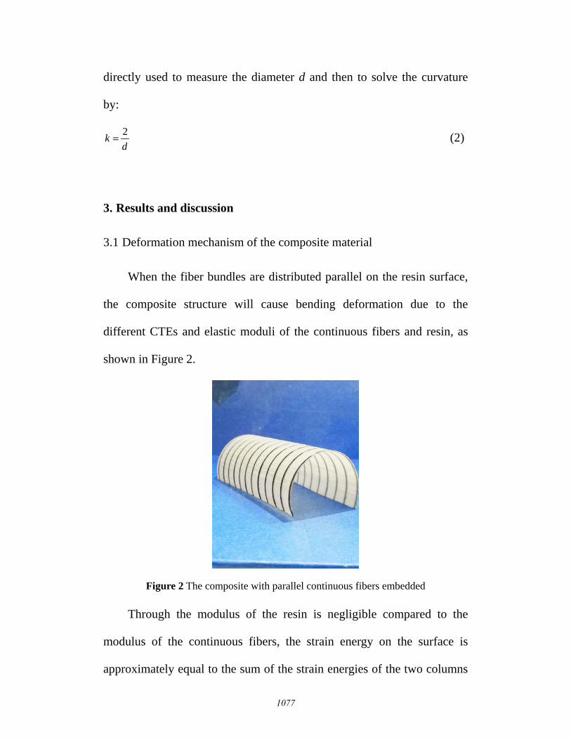
When the fiber bundles are distributed parallel on the resin surface,
the composite structure will cause bending deformation due to the
different CTEs and elastic moduli of the continuous fibers and resin, as
shown in Figure 2.
Figure 2 The composite with parallel continuous fibers embedded
Through the modulus of the resin is negligible compared to the
modulus of the continuous fibers, the strain energy on the surface is
approximately equal to the sum of the strain energies of the two columns
1077

of fiber bundles:
)(21 22
baEe εε ∆+∆≈∆ (3)
where Δε is the strain energy difference between when two columns of
fiber bundles exist together and when one column of fiber bundles exist
alone.
For a point in the composite structure, assuming that its distance
from the neutral surface is d, and the length of the neutral surface is l0,
therefore:
000 )( lkkd −′=−′=∆ εεε (4)
where k0 and ε0 are the curvature of the neutral surface and the strain at
the height of that point when a column of fiber bundles exists alone. k’
and ε’ are the curvature of the neutral surface and the strain at the height
of that point when two columns of fiber bundles exist together. Therefore,
20
20 )()( bbaa kkkke −+−∝∆ (5)
According to the Euler formula of differential geometry, the
following equation can be obtained:
221
221 ))(cos()cos( αθα −−+−∝∆ kkkke ba (6)
where θ is the angle between two fiber bundles and α is the angle
between the direction of the principal curvature and one of the fiber
bundles.
1078

For our 4D printing process, ka and kb are all the curvature when a
column of fiber bundles exists alone, so ka=kb. In order to make the △e
minimum, the α and k1 (the principal curvature of the surface) can be
solved:
=
=
2cos
2
21 θ
θα
akk (7)
To verify this equation, we printed rectangular composite panels with
different angles (30°, 60° and 90°) between two columns of fiber bundles.
Figure 3 The direction of the curvature is along the angular bisector between fibers
The relationship between the size and the direction of the principal
1079

curvature and the angle of fiber bundles are shown in Figure 4 and 5.
Figure 4 The relationship between the size of the curvature and the angle of fiber bundles
Figure 5 The relationship between the direction of the curvature and the angle of fiber bundles
According to the theory and experiment, we can get the law that the
principal curvature direction of the bilayer surface is in the direction of
0 30 60 90
1.0
1.2
1.4
1.6
1.8
2.0
k1/k
a
θ(°)
Theoretical value
Experimental value
0 30 60 90
0
20
40
direction o
f k
1(°
)
θ(°)
Theoretical value
Experimental value
1080

the bisector of the sharp angle between the fiber bundles, and the
principal curvature value of the bilayer surface is proportional to sec2θ.
With this rule, we can design more complex developable surfaces.
3.2 Deformation design of a complex surface
Let’s take a conical surface )cot,sin,cos( γuvuvu=r as an example,
where u, v are two parameters of the cone, and γ is the half vertex angle
of the cone. Solve the value and the direction of the non-zero principal
curvature, and the value of the non-zero principal curvature is:
uk γcos
1 = (8)
It can be seen that the curvature of the position closer to the conical
vertex is larger, as shown in Figure 6a. The direction of the curvature is
along the direction of the weft of the cone (Figure 6b).
Figure 6 The size and the direction of the curvature of a cone
The cone is changed into a plane by isometric transformation, and
1081

the principal curvature can be expressed by the plane coordinate system
(ρ, θ), as shown in Figure 7.
ργcot
1 =k (9)
Figure 7 The principal curvature line after isometric transformation
Rearrange Equation 7 and 9, then the angle λ between the orientation
of fibers and the direction of non-zero principal curvature can be
obtained:
γρλ
cotcos
1
aa kkk ±=±= (10)
In polar coordinates,
ρρλ
′=tan (11)
Rearrange Equation 10 and 11, then the equation for the fiber
trajectory can be obtained:
)cot(dd ργρθρ −±=
ak (12)
1082
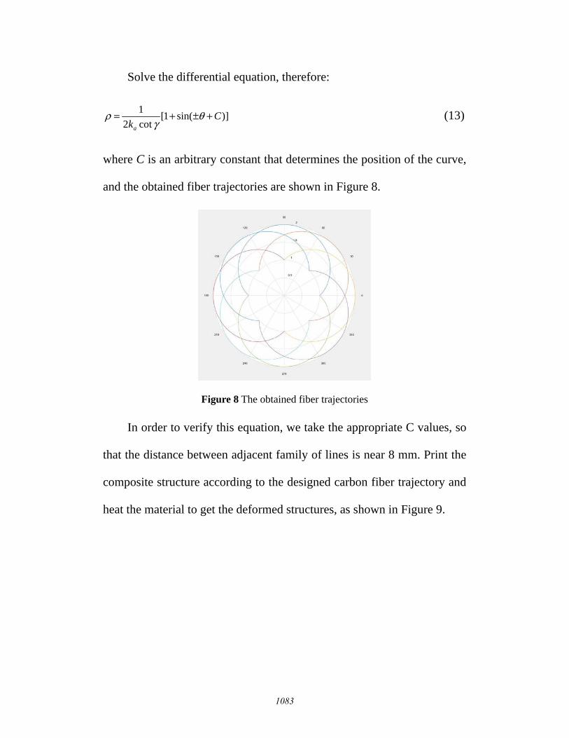
Solve the differential equation, therefore:
)]sin(1[cot21 C
ka
+±+= θγ
ρ (13)
where C is an arbitrary constant that determines the position of the curve,
and the obtained fiber trajectories are shown in Figure 8.
Figure 8 The obtained fiber trajectories
In order to verify this equation, we take the appropriate C values, so
that the distance between adjacent family of lines is near 8 mm. Print the
composite structure according to the designed carbon fiber trajectory and
heat the material to get the deformed structures, as shown in Figure 9.
1083

Figure 9 The cone prepared by 4D printing
In order to verify the deformation accuracy, we printed many conical
surfaces with designed fiber trajectories and cylindrical surfaces with
parallel fiber trajectories. In each group of experiments, the printing
parameters and the heat treatment parameters of the cone and the cylinder
are exactly the same. The Ka calculated by the curvature of the bottom
surface of a conical surface is called the calculated curvature, and the
curvature measured by a cylindrical surface is called the experimental
curvature. The two curvatures are compared, and the results are shown in
Table 1. It can be seen that the error between calculated curvature and
experimental curvature is between 3-8 %, indicating higher deformation
accuracy.
Table 1 Comparison of experimental curvature and calculated curvature
Group Experimental curvature Calculated curvature Error
1 0.02477 0.02295 7.35%
1084

2 0.01511 0.01457 3.57%
3 0.06670 0.06119 8.26%
4 0.04833 0.04543 6.00%
According to this method, any developable surface can be prepared
by this 4D printing process. The specific solution is still to get the main
curvature lines of the curved surface first, then transform it into a plane
curve by isometric transformation, and finally get the fiber trajectory.
4. Conclusion
We used 4D printing technology to prepare continuous fiber
embedded composites. Due to the different elastic moduli and CTEs of
continuous fibers and resin, the composite structure will have different
flexural curvature at different temperatures. It is found that when the fiber
bundles are aligned in parallel, the direction of principal curvature is
along the fiber orientation. When two columns of fiber bundles are
distributed on the surface of the resin, the direction of curvature is along
the bisector of the angle θ between the intersecting fiber bundles, and the
size of the curvature is proportional to sec2θ. With this rule, we can
design more complex surfaces, such as a cone. This 4D printing process
has good designability and deformation accuracy.
1085

Reference
[1] F. Momeni, S. M. Mehdi Hassani. N, X. Liu, J. Ni, MATER DESIGN 2017, 122, 42.
[2] J. Wu, C. Yuan, Z. Ding, I. Michael, Y. Mao, SCI REP-UK 2016, 6, 1.
[3] Z. Ding, C. Yuan, X. Peng, T. Wang, H. J. Qi, Science Advance 2017, 3.
[4] Q. Ge, S. A. Hosein, L. Howon, C. K. Dunn, N. X. Fang, SCI REP-UK 2016, 6, 1.
[5] P. Fratzl, R. Elbaum, I. Burgert, FARADAY DISCUSS 2008, 139, 275.
[6] R. Elbaum, L. Zaltzman, I. Burgert, P. Fratzl, SCIENCE 2007, 316, 884.
[7] J. U. Schmied, H. Le Ferrand, P. Ermanni, A. R. Studart, A. F. Arrieta, BIOINSPIR BIOMIM 2017, 12, 1.
[8] A. S. Gladman, E. A. Matsumoto, R. G. Nuzzo, L. Mahadevan, J. A. Lewis, NAT MATER 2016, 15, 413.
[9] X. Tian, T. Liu, C. Yang, Q. Wang, D. Li, Composites: Part A 2016, 88, 198.
1086