4dcad and visualization in construction
TRANSCRIPT

7/14/2019 4DCAD and Visualization in Construction
http://slidepdf.com/reader/full/4dcad-and-visualization-in-construction-56327c6a084e9 1/296

7/14/2019 4DCAD and Visualization in Construction
http://slidepdf.com/reader/full/4dcad-and-visualization-in-construction-56327c6a084e9 2/296
4D CAD and Visualization in Construction

7/14/2019 4DCAD and Visualization in Construction
http://slidepdf.com/reader/full/4dcad-and-visualization-in-construction-56327c6a084e9 3/296
7/14/2019 4DCAD and Visualization in Construction
http://slidepdf.com/reader/full/4dcad-and-visualization-in-construction-56327c6a084e9 4/296
4D CAD and Visualization in
Construction: Developmentsand Applications
Raja R.A. Issa
Ian Flood
William J. O’Brien
University of Florida, Gainesville, USA
A.A. BALKEMA PUBLISHERS LISSE /ABINGDON /EXTON (PA)/TOKYO

7/14/2019 4DCAD and Visualization in Construction
http://slidepdf.com/reader/full/4dcad-and-visualization-in-construction-56327c6a084e9 5/296
Library of Congress Cataloging-in-Publication Data
(applied for )
Cover design: Studio Jan de Boer, Amsterdam, the Netherlands
© 2003 Swets & Zeitlinger B.V., Lisse
All rights reserved. No part of this publication may be reproduced, stored in a retrieval system, or
transmitted in any form or by any means, electronic, mechanical, by photocopying, recording or
otherwise, without the prior written permission of the publishers.
Although all care is taken to ensure the integrity and quality of this publication and the informationherein, no responsibility is assumed by the publisher nor the author for any damage to property or
persons as a result of operation or use of this publication and/or the information contained herein.
Published by: A.A. Balkema Publishers, a member of Swets & Zeitlinger Publishers
www.balkema.nl and www.szp.swets.nl
ISBN 90 5809 354 9
This edition published in the Taylor & Francis e-Library, 2005.
“To purchase your own copy of this or any of Taylor & Francis or Routledge’s
collection of thousands of eBooks please go to www.eBookstore.tandf.co.uk.”
ISBN 0-203-97112-4 Master e-book ISBN
(Print Edition)

7/14/2019 4DCAD and Visualization in Construction
http://slidepdf.com/reader/full/4dcad-and-visualization-in-construction-56327c6a084e9 6/296
Table of contents
Foreword VII
Benefits of 3D and 4D Models for Facility Managers and 1AEC Service Providers
Martin Fischer, John Haymaker, Kathleen Liston
Beyond Sphereland: 4D CAD in Construction Communications 33
Dennis Fukai
Fully Integrated and Automated Project Process (FIAPP) 55for the Project Manager and ExecutiveF.H. (Bud) Griffis, Carrie S. Sturts
New Construction Management Practice Based on the 75Virtual Reality Technology
Jarkko Leinonen, Kalle Kähkönen, Tero Hemiö, Arkady Retik, Andrew Layden
4D CAD and Dynamic Resource Planning for Subcontractors: 101Case Study and IssuesWilliam J. O’Brien
The Role of 4D Modeling in Trade Sequencing and 125
Production Planning David Riley
The Link Between Design and Process: Dynamic Process 145Simulation Models of Construction Activities
E. Sarah Slaughter
V

7/14/2019 4DCAD and Visualization in Construction
http://slidepdf.com/reader/full/4dcad-and-visualization-in-construction-56327c6a084e9 7/296
Acknowledging Variability and Uncertainty in Product and 165Process Development
Iris D. Tommelein
Application of 4D CAD in the Construction Workplace 195 Richard J. Coble, Robert L. Blatter, Indrid Agaj
Virtually Real Construction Components and Processes 211for Design-For-Safety-Process (DFSP)Steve Rowlinson, Bonaventura H.W. Hadikusumo
The Potential of 4D CAD as a Tool for Construction Management 227
Robert M. Webb, Theo C. Haupt
Virtual Reality: A Solution to Seamless Technology Integration 243in the AEC Industry?
Raja R.A. Issa
Construction Management Pull for nD CAD 261Peter Barrett
Closure 281 R.R.A. Issa, I. Flood, W.J. O’Brien
Index 285
VI Table of contents

7/14/2019 4DCAD and Visualization in Construction
http://slidepdf.com/reader/full/4dcad-and-visualization-in-construction-56327c6a084e9 8/296
Foreword
The final frontier of the application of information technology in construction isthe job site. And perhaps there is no stronger technological link between the jobsite and the design office than the practice of 4D CAD, and for good reason.Implementing a 4D CAD system cuts to the very heart of issues that mankind hasstruggled with for centuries: linking space and time; turning concept into reality;ownership of knowledge; effective communication between business partners.
Models have been used for centuries to explain what is to be built, and thepromise of this new technology is exciting. Never before in history has man, with-
out ever turning a single shovel of earth or driving a single nail, been able to vir-tually construct a bridge or building one piece at a time and link each step to acorresponding step on a schedule.
Nonetheless, entrenched ways of working do not change overnight. At the timeof writing, the flurry of activity with dot.com investments and startups has slowedto a trickle. It comes as no surprise to many industry observers that many of thequick fixes with technology promised by these startups failed to take hold. Whatdid take place, however, was a demonstration that the construction industry con-
tinues to be ripe and ready for new technologies that will provide value.A problem still plaguing the industry is that many in it are not in sync with the
technology. A growing body of workers is well versed in the ways of the computer,but novice at best in the ways of construction. Juxtapose that with a still significantlysized body of industry veterans that have yet to embrace technology. Arguments canbe made in support of delays to widespread adoption of 4D CAD are that the tech-nology is not evolved enough for the people, or that the people are not evolvedenough to use the technology—both viewpoints are valid. Those assertions are, at adeeper level, the continuing story of mankind’s relationship with his tools.
Using contractual methods such as design-build to force parties to work together, rather than technological tools, has met with some success. On the hori-zon, it could also be a driving force to help the growth of 4D CAD. Superficially,a simple schedule and a CAD model may qualify as 4D CAD. Yet to make thepractice truly widespread, deeper issues such as trade sequencing, productionplanning and dynamic cost and resource planning need to be addressed.
VII

7/14/2019 4DCAD and Visualization in Construction
http://slidepdf.com/reader/full/4dcad-and-visualization-in-construction-56327c6a084e9 9/296
No industry needs 4D CAD more than construction. Like NASA’s SpaceProgram, and the developments borne from it that ultimately benefited mankind asa whole, 4D CAD is similarly poised to have a major impact on any industry,
including construction, that struggles to simultaneously manage the scheduledcreation of objects, be they airplanes, airports or air cleaners.When designers have a better grasp of scheduling and buildability issues facing
contractors, projects will be better. Similarly, when contractors are more involvedearlier in the process, buildability issues will be dealt with on screen or on paper,instead of in situ. And without the disputes, disagreements and the rampant adver-sarial relationship that so often plagues construction projects today, designers andconstructors can better concentrate on what they want most, which is ultimatelyto build.
Matthew PhairSenior Editor
Engineering News-Record
VIII Foreword

7/14/2019 4DCAD and Visualization in Construction
http://slidepdf.com/reader/full/4dcad-and-visualization-in-construction-56327c6a084e9 10/296
BENEFITS OF 3D AND 4D MODELS FOR FACILITYMANAGERS AND AEC SERVICE PROVIDERS
Martin Fischer1, John Haymaker2, Kathleen Liston2
1Civil and Environmental Engineering and (by courtesy) Computer Science,
Stanford, CA, USA2Civil and Environmental Engineering, Stanford, CA, USA
1
Abstract
The first part of this paper presents an extensive list of benefits users of 4D models have
realized and illustrates the benefits with specific examples from actual uses on a variety of
projects. It illustrates how current business practices and project delivery approaches allow
or do not allow facility owners to reap these benefits. All owners and AEC service providers(designers, general contractors, subcontractors) who have used 4D models to assist in
understanding, analyzing and communicating a design and construction schedule have
reported benefits from the use of these models. Owners have used 4D models to plan the
construction of facilities that require significant phasing prior to contract award to verify
the overall constructibility of a proposed design given the project timeline and available
space. General contractors have used 4D models for overall and for detailed construction
planning, to communicate scope and schedule information effectively to subcontractors and
other parties, and to test the constructibility of the design and the executability of the sched-
ule prior to committing resources to the field. The second part of the paper describes indetail the application of 4D models for construction scheduling and constructibility analy-
sis on the Walt Disney Concert Hall in Los Angeles. It discusses the reasons for the use of
4D models on the project and details the technical challenges the 4D modeler had to over-
come. Specific examples of the impact of the 4D model on the schedule are also shown.
Keywords: 4D modeling, construction planning, case studies, benefits
INTRODUCTION
Traditional construction planning tools, such as bar charts and network diagrams,do not represent and communicate the spatial and temporal, or 4D, aspects of con-struction schedules effectively. Consequently, they do not allow project managers
7/14/2019 4DCAD and Visualization in Construction
http://slidepdf.com/reader/full/4dcad-and-visualization-in-construction-56327c6a084e9 11/296
to create schedule alternatives rapidly to find the best way to build a particulardesign. Extending the traditional planning tools, visual 4D models combine 3DCAD models with construction activities to display the progression of construc-
tion over time. 4D models combine 3D CAD models with the project timeline(Cleveland, 1989). Systems linking 3D CAD models with schedule and otherproject information started to be developed in the mid-eighties (Kahan & Madrid,1987; Atkins, 1988). Experience on many different types of projects (simple tocomplex, new to retrofit) has shown that combining scope and schedule informa-tion in one visual model is a powerful communication and collaboration tool fortechnical and non-technical stakeholders (Williams, 1996; Retik, 1997; Edwards &Bing, 1999).
The 4D research team at Stanford University has tested the usefulness of visual4D models in planning the construction of a hospital, the roof of a universitybuilding, a small commercial building, a Frank Gehry designed museum, a themepark, and a Frank Gehry designed concert hall. These cases have shown that moreproject stakeholders can understand a construction schedule more quickly andcompletely with 4D visualizations than with the traditional construction manage-ment tools. Since they understand the scope and schedule of a project better, thestakeholders can then provide input to the scope and schedule and the importantinterrelationships, and help improve the project design and schedule. We and other
3D and 4D practitioners found that project managers using 4D models are morelikely to allocate resources (e.g. design time, client review time, management atten-tion, construction crews) more effectively than those who do not use 4D models.Danhier et al. (1994) came to similar conclusions in their application of 4D modelsto the replacement of steam generators.
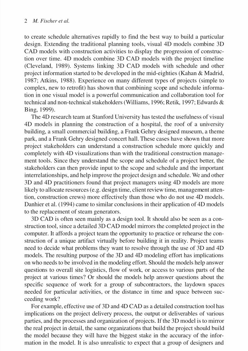
3D CAD is often seen mainly as a design tool. It should also be seen as a con-struction tool, since a detailed 3D CAD model mirrors the completed project in thecomputer. It affords a project team the opportunity to practice or rehearse the con-
struction of a unique artifact virtually before building it in reality. Project teamsneed to decide what problems they want to resolve through the use of 3D and 4Dmodels. The resulting purpose of the 3D and 4D modeling effort has implicationson who needs to be involved in the modeling effort. Should the models help answerquestions to overall site logistics, flow of work, or access to various parts of theproject at various times? Or should the models help answer questions about thespecific sequence of work for a group of subcontractors, the laydown spacesneeded for particular activities, or the distance in time and space between suc-
ceeding work?For example, effective use of 3D and 4D CAD as a detailed construction tool hasimplications on the project delivery process, the output or deliverables of variousparties, and the processes and organization of projects. If the 3D model is to mirrorthe real project in detail, the same organizations that build the project should buildthe model because they will have the biggest stake in the accuracy of the infor-mation in the model. It is also unrealistic to expect that a group of designers and
2 M. Fischer et al.

7/14/2019 4DCAD and Visualization in Construction
http://slidepdf.com/reader/full/4dcad-and-visualization-in-construction-56327c6a084e9 12/296
modelers has all the expertise about construction details necessary for a detailed 3Dmodel. The experience of the 4D research group at the Center for IntegratedFacility Engineering (CIFE) at Stanford University shows that including at least
key subcontractors as design-build firms from the beginning of a project makesdetailed 3D modeling more efficient and effective than including them later (Staubet al., 1999).
It is difficult for designers to know to what level of detail they should model aparticular part of a project, since they often do not benefit directly from accuratedetailed 3D models that clearly show what needs to be built. We have found thatthe subcontractors, however, are very interested in having accurate, reliable, andwell-coordinated detailed design information because they can leverage that infor-mation in material procurement and management, and in planning and scheduling.Building a 3D CAD model in this way leaves accountability for the correctness of the information in the 3D model with the firms who are best equipped to leveragethe investment in building 3D models. Designers remain in charge of the overalldesign concept, and subcontractors can focus on streamlining the production of their part of a project.
A detailed and well-coordinated 3D CAD model allows firms to prefabricatedirectly from the model and improves material management. In this way, 3D CADmodels enable project managers to allocate and use material resources more effi-
ciently. 4D models extend the usefulness of design information to the constructionplanning and construction phases. If 4D models are built during the design phasethey can help provide constructibility feedback to the design team, and they canalso help set priorities for design work so that the necessary material procurementand crew planning information for construction are available in a timely manner.In this way, 4D CAD models help project managers to manage the flow of work and the allocation of crews and space on construction sites better (Vaugn, 1996). Thenext sections introduce benefits companies using 3D and 4D CAD models have
realized in more detail. The later sections in this paper give specific examples of uses of 4D models and describe the parties that participated in the modeling effortsand discuss the level of detail they found useful.
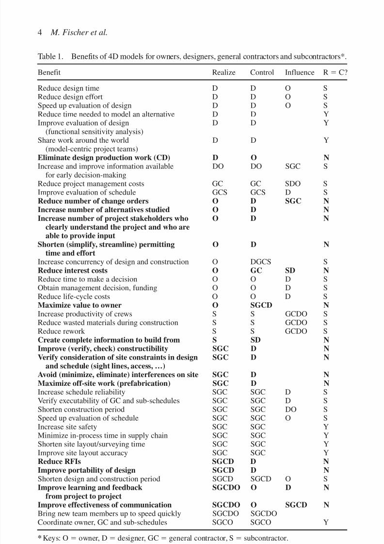
Table 1 lists benefits of 3D and 4D models realized by companies using suchmodels for design and construction. Engineers and managers from owner, design,and construction firms reported them at a workshop on the use of 3D and 4D mod-els hosted by Walt Disney Imagineering (WDI) and CIFE in May 1999.
The column on the left lists specific benefits users have reported, the two mid-
dle columns show who realizes the benefit and who has most control and influ-ence over the information in the 4D model necessary to realize the benefit. Thecolumn on the right shows whether the beneficiary matches the controlling party.Y means that it does, N means that it does not and S means “somewhat”, i.e. theprimary beneficiary has significant control over the information in the 4D modelnecessary to realize the benefit, but other parties have some influence as well. Rowswhere the party that realizes the benefit does not match with the party controlling
Benefits of 3D and 4D models 3
7/14/2019 4DCAD and Visualization in Construction
http://slidepdf.com/reader/full/4dcad-and-visualization-in-construction-56327c6a084e9 13/296
4 M. Fischer et al.
Table 1. Benefits of 4D models for owners, designers, general contractors and subcontractors*.
Benefit Realize Control Influence Rϭ C?
Reduce design time D D O SReduce design effort D D O SSpeed up evaluation of design D D O SReduce time needed to model an alternative D D YImprove evaluation of design D D Y
(functional sensitivity analysis)Share work around the world D D Y
(model-centric project teams)Eliminate design production work (CD) D O NIncrease and improve information available DO DO SGC S
for early decision-making
Reduce project management costs GC GC SDO SImprove evaluation of schedule GCS GCS D SReduce number of change orders O D SGC NIncrease number of alternatives studied O D NIncrease number of project stakeholders who O D N
clearly understand the project and who areable to provide input
Shorten (simplify, streamline) permitting O D Ntime and effort
Increase concurrency of design and construction O DGCS SReduce interest costs O GC SD N
Reduce time to make a decision O O D SObtain management decision, funding O O D SReduce life-cycle costs O O D SMaximize value to owner O SGCD NIncrease productivity of crews S S GCDO SReduce wasted materials during construction S S GCDO SReduce rework S S GCDO SCreate complete information to build from S SD NImprove (verify, check) constructibility SGC D NVerify consideration of site constraints in design SGC D N
and schedule (sight lines, access, …)
Avoid (minimize, eliminate) interferences on site SGC D NMaximize off-site work (prefabrication) SGC D NIncrease schedule reliability SGC SGC D SVerify executability of GC and sub-schedules SGC SGC D SShorten construction period SGC SGC DO SSpeed up evaluation of schedule SGC SGC O SIncrease site safety SGC SGC YMinimize in-process time in supply chain SGC SGC YShorten site layout/surveying time SGC SGC YImprove site layout accuracy SGC SGC YReduce RFIs SGCD D N
Improve portability of design SGCD D NShorten design and construction period SGCD SGCD O SImprove learning and feedback SGCDO O D N
from project to projectImprove effectiveness of communication SGCDO O SGCD NBring new team members up to speed quickly SGCDO SGCDOCoordinate owner, GC and sub-schedules SGCO SGCO Y
* Keys: O ϭ owner, Dϭ designer, GCϭ general contractor, S ϭ subcontractor.

7/14/2019 4DCAD and Visualization in Construction
http://slidepdf.com/reader/full/4dcad-and-visualization-in-construction-56327c6a084e9 14/296
or generating the information are shown in bold. The assignments to who controlsthe data and who realizes a benefit assume a traditional project delivery process.Table 1 shows that many benefits that potentially translate into significant time
and cost savings are unlikely to be realized with a traditional project organizationbecause the party benefiting from the use of 3D and 4D models is not in controlof the information necessary to realize the benefit.
Benefits for designers
It is commonly understood that a design documented with a 3D CAD model willmost likely have fewer errors and coordination issues because the construction of the model by multiple designers forces and allows them to reconcile inconsisten-
cies. Evaluation of a design in 3D is also faster than with 2D drawings becausereviewers can more quickly understand the scope and status of the design.Workshop participants who have been using 3D CAD models for several yearsreported that, after an initial learning curve, the overall design effort and designtime is less than with a process using 2D drawings. They use 3D even when theclient asks for 2D drawings because design revisions are faster and need to be doneonly once (instead of updating plans, sections, elevations and details). A furtherbenefit is the potential to eliminate construction documents. Most participants saw
little value in most 2D construction documents currently produced by design firms.On many projects subcontractors complete a new set of shop drawings anyway, andin some cases subcontractors fabricate parts directly from the 3D CAD model withnumerically-controlled machines. 2D construction documents and shop drawingsappear to be rather useless on a project where the design is documented and sharedwith a detailed 3D CAD model. Designers involved in projects that used 3D mod-els from design through construction reported that they saw an increased coordina-tion effort during the design phase of the project followed by fewer requests forinformation during construction. Hence, designers were able to focus on the phase
of the project they enjoy most.
Benefits for owners
Owners are, of course, the ultimate beneficiaries of better performance by design-ers and builders from the use of 3D and 4D models. The workshop participantsnoted, however, that owners can use 3D and 4D models themselves to speed up andimprove decision-making and to involve many more stakeholders than traditionallypossible. For example, WDI was able to get the input from about 400 stakeholdersduring the two-month pre-bid design and construction schedule review for theParadise Pier portion of Disney’s California Adventure. They were holding meet-ings with groups of eight to ten people at a time in their Computer-Assisted VirtualEnvironment (CAVE). The groups could interactively review the proposed designand construction schedule from any perspective and quickly understand the design,schedule, and corresponding constraints (Fischer et al., 2001).
Benefits of 3D and 4D models 5
7/14/2019 4DCAD and Visualization in Construction
http://slidepdf.com/reader/full/4dcad-and-visualization-in-construction-56327c6a084e9 15/296
Benefits for builders
All participants at the workshop who have labor risk on site reported that detailed3D and 4D models greatly increase the productivity of crews and help eliminate
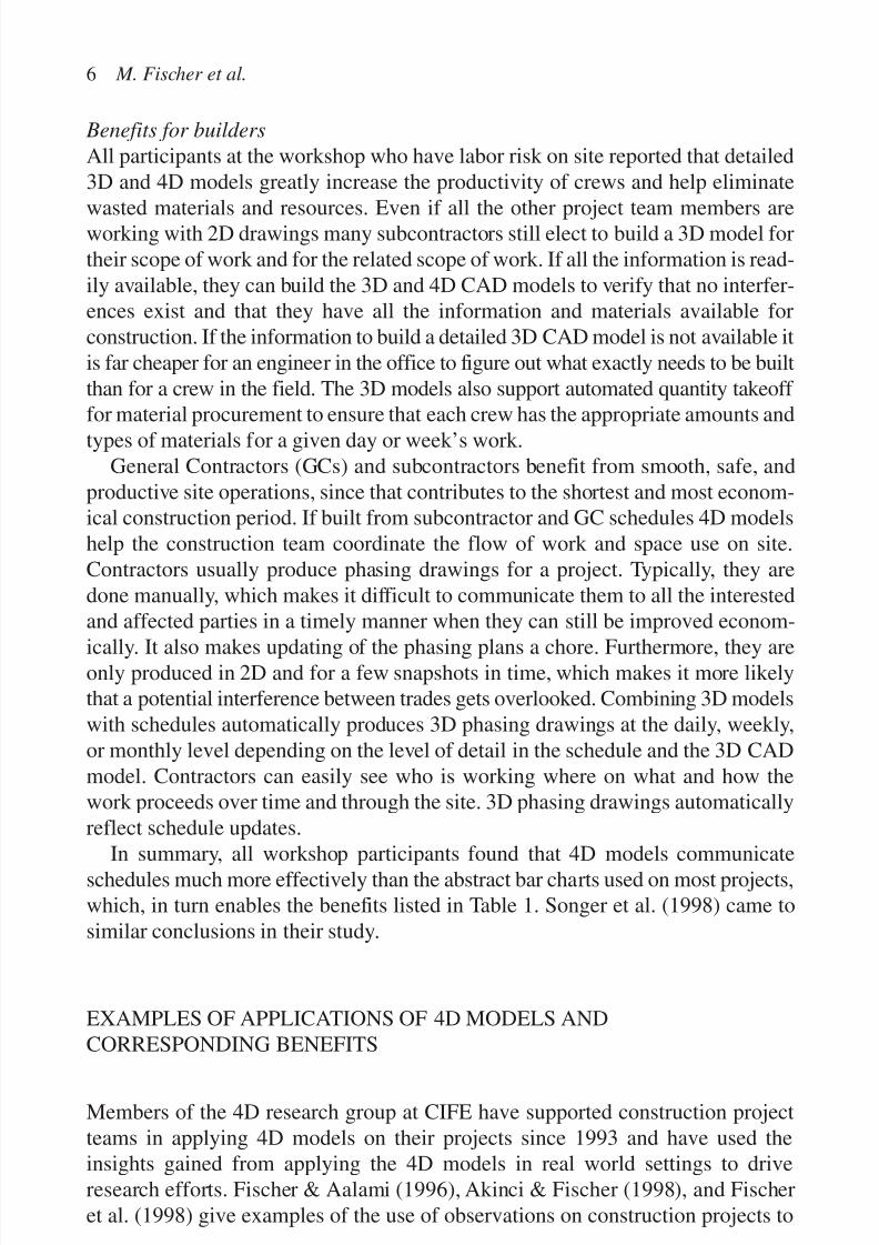
wasted materials and resources. Even if all the other project team members areworking with 2D drawings many subcontractors still elect to build a 3D model fortheir scope of work and for the related scope of work. If all the information is read-ily available, they can build the 3D and 4D CAD models to verify that no interfer-ences exist and that they have all the information and materials available forconstruction. If the information to build a detailed 3D CAD model is not available itis far cheaper for an engineer in the office to figure out what exactly needs to be builtthan for a crew in the field. The 3D models also support automated quantity takeoff for material procurement to ensure that each crew has the appropriate amounts andtypes of materials for a given day or week’s work.
General Contractors (GCs) and subcontractors benefit from smooth, safe, andproductive site operations, since that contributes to the shortest and most econom-ical construction period. If built from subcontractor and GC schedules 4D modelshelp the construction team coordinate the flow of work and space use on site.Contractors usually produce phasing drawings for a project. Typically, they aredone manually, which makes it difficult to communicate them to all the interestedand affected parties in a timely manner when they can still be improved econom-
ically. It also makes updating of the phasing plans a chore. Furthermore, they areonly produced in 2D and for a few snapshots in time, which makes it more likelythat a potential interference between trades gets overlooked. Combining 3D modelswith schedules automatically produces 3D phasing drawings at the daily, weekly,or monthly level depending on the level of detail in the schedule and the 3D CADmodel. Contractors can easily see who is working where on what and how thework proceeds over time and through the site. 3D phasing drawings automaticallyreflect schedule updates.
In summary, all workshop participants found that 4D models communicateschedules much more effectively than the abstract bar charts used on most projects,which, in turn enables the benefits listed in Table 1. Songer et al. (1998) came tosimilar conclusions in their study.
EXAMPLES OF APPLICATIONS OF 4D MODELS ANDCORRESPONDING BENEFITS
Members of the 4D research group at CIFE have supported construction projectteams in applying 4D models on their projects since 1993 and have used theinsights gained from applying the 4D models in real world settings to driveresearch efforts. Fischer & Aalami (1996), Akinci & Fischer (1998), and Fischeret al. (1998) give examples of the use of observations on construction projects to
6 M. Fischer et al.

7/14/2019 4DCAD and Visualization in Construction
http://slidepdf.com/reader/full/4dcad-and-visualization-in-construction-56327c6a084e9 16/296
formulate research questions, help formalize specific knowledge, and test researchprototypes. This section briefly discusses these applications of 4D modeling andsummarizes the corresponding benefits. In our experience, 4D models offer bene-
fits on simple and complex projects, on new construction and on retrofit projects,and at the detailed nuts and bolt level as well as for overall project phasing. Unlessnoted otherwise, we used the Bentley Schedule Simulator or an earlier versionof this program to combine 3D CAD and schedule information. Most projectswere modeled in 3D with AutoCAD, and the schedule information was mostly inPrimavera’s P3 tool, although MS Project has also been used. These brief descrip-tions are followed by an in-depth case study.
1993–95: RECONSTRUCTION OF THE SAN MATEO COUNTYHEALTH CENTER
Together with the GC, Dillingham Construction Company, CIFE researchers build3D and 4D models to coordinate the overall master plan so that the five-year con-struction period interfered as little as possible with the operation of the hospital.The 4D model coordinated owner relocation and operations schedules with con-
struction schedules, facilitated client input, eased relationships with the commu-nity, and became, according to the hospital director, the best fund-raising tool(Collier & Fischer, 1996). It allowed, for example, verification that hospital staff could always reach all parts of the hospital from any other part without leaving thehospital. A more detailed 4D model was used to verify the constructibility of thecentral utilities plant and to make sure that the design and schedule informationwere complete and well coordinated. The 4D model for the US $100 m, 320,000 sf project was built from about 25,000 3D CAD elements and 500 activities in about
1,000 hours. The 4D model to study the overall phasing of the project consistedessentially of the main architectural components of the project: walls, windows,doors, columns, slabs, roofs. The 4D model for the central utilities plant was moredetailed and included the foundations, some of the stud walls, the equipment plat-forms and equipment and the major mechanical ductwork. Collier & Fischer(1995) provide detailed information on the 4D modeling effort required for thisproject. The 4D modeling effort was carried out in parallel to the GCs construc-tion planning efforts. Hence the 4D modeling effort served to confirm the project
manager’s thinking about his approach to construction. It also helped the projectmanager communicate how hospital operations and construction were going tocoexist in close proximity for the scheduled five-year duration of the project.
The paragraphs below explain how 4D modeling helped improve the construc-tion schedule for the San Mateo County Health Center. Figures 1 to 8 show eightstages in the reconstruction of the San Mateo County Health Center project overthe planned five-year construction period from May 1994 to June 1999. The first
Benefits of 3D and 4D models 7

7/14/2019 4DCAD and Visualization in Construction
http://slidepdf.com/reader/full/4dcad-and-visualization-in-construction-56327c6a084e9 17/296
8 M. Fischer et al.
Figure 1. May 1994. Site with existing buildings, Main Hospital at left, ClinicsBuilding at right foreground, East Wing in between, Existing Utilities plant in middle,
Aids Clinics at top right.
Figure 2. March 1995. As work on the new Central Utilities Plant proceeds as thecritical activity, construction on the first half of the North Addition begins. Trailers fortemporary office space are installed next to the Clinics building. The first portion of theCentral Hub is under construction (shown in green in the center of the snapshot). Thehospital operations are linked through the existing East Wing (shown in gray in the
center of the snapshot).
Figure 3. October 1995. Central Plant is completed, North Addition interior work is beingcompleted. Aids Clinics is now in trailers. Aids Clinics is demolished and work hasbegun on new Nursing Wing.
7/14/2019 4DCAD and Visualization in Construction
http://slidepdf.com/reader/full/4dcad-and-visualization-in-construction-56327c6a084e9 18/296
Benefits of 3D and 4D models 9
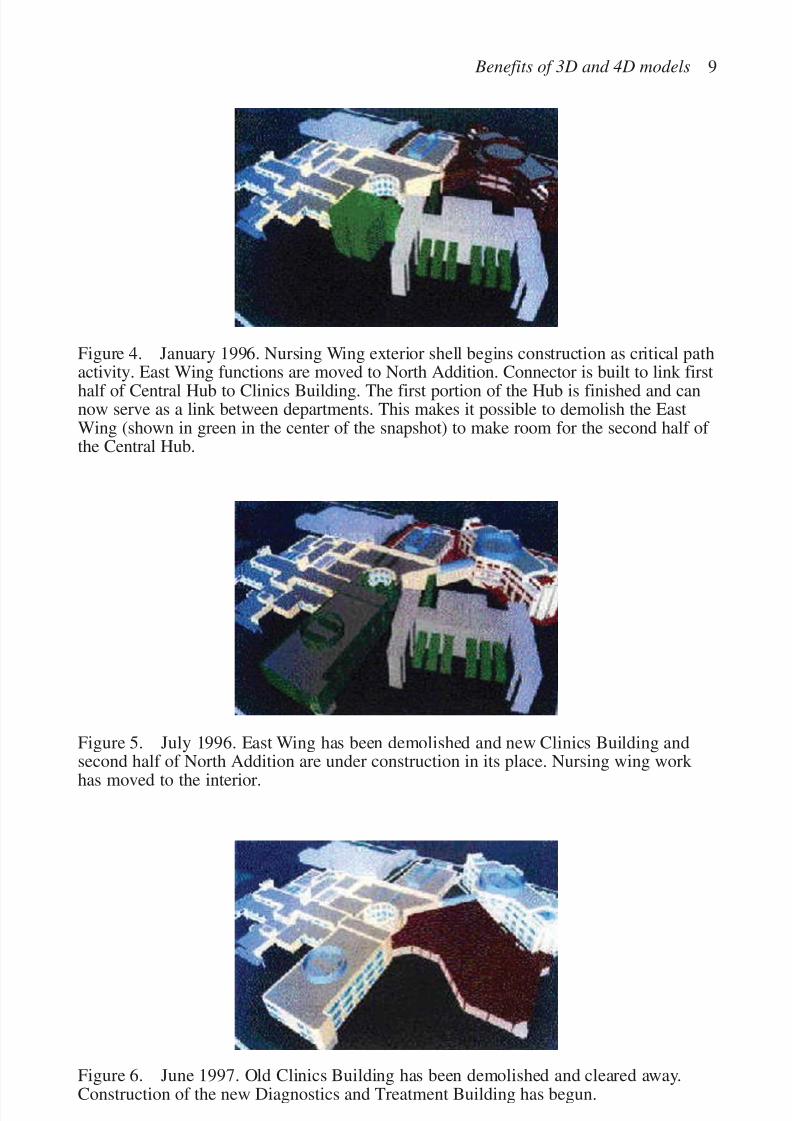
Figure 4. January 1996. Nursing Wing exterior shell begins construction as critical pathactivity. East Wing functions are moved to North Addition. Connector is built to link first
half of Central Hub to Clinics Building. The first portion of the Hub is finished and cannow serve as a link between departments. This makes it possible to demolish the EastWing (shown in green in the center of the snapshot) to make room for the second half of the Central Hub.
Figure 5. July 1996. East Wing has been demolished and new Clinics Building andsecond half of North Addition are under construction in its place. Nursing wing work has moved to the interior.
Figure 6. June 1997. Old Clinics Building has been demolished and cleared away.Construction of the new Diagnostics and Treatment Building has begun.
7/14/2019 4DCAD and Visualization in Construction
http://slidepdf.com/reader/full/4dcad-and-visualization-in-construction-56327c6a084e9 19/296
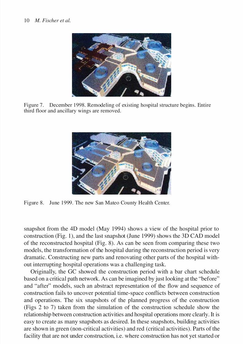
snapshot from the 4D model (May 1994) shows a view of the hospital prior to
construction (Fig. 1), and the last snapshot (June 1999) shows the 3D CAD modelof the reconstructed hospital (Fig. 8). As can be seen from comparing these twomodels, the transformation of the hospital during the reconstruction period is verydramatic. Constructing new parts and renovating other parts of the hospital with-out interrupting hospital operations was a challenging task.
Originally, the GC showed the construction period with a bar chart schedulebased on a critical path network. As can be imagined by just looking at the “before”and “after” models, such an abstract representation of the flow and sequence of
construction fails to uncover potential time-space conflicts between constructionand operations. The six snapshots of the planned progress of the construction(Figs 2 to 7) taken from the simulation of the construction schedule show therelationship between construction activities and hospital operations more clearly. It iseasy to create as many snapshots as desired. In these snapshots, building activitiesare shown in green (non-critical activities) and red (critical activities). Parts of thefacility that are not under construction, i.e. where construction has not yet started or
10 M. Fischer et al.
Figure 8. June 1999. The new San Mateo County Health Center.
Figure 7. December 1998. Remodeling of existing hospital structure begins. Entirethird floor and ancillary wings are removed.

7/14/2019 4DCAD and Visualization in Construction
http://slidepdf.com/reader/full/4dcad-and-visualization-in-construction-56327c6a084e9 20/296
where construction has been completed, are shown in gray and yellow (the originalcolors in the 3D model).
The following example illustrates the usefulness of 4D models to support mas-
ter planning. We have also tested the usefulness of 4D models for more detailedplanning and found them to be extremely helpful for the coordination of contrac-tors and for constructibility improvements (see the other case studies in this paper).The 4D model, from which the snapshots are taken, took about four person-monthsto build.
Instead of focusing on all the activities that are shown in the snapshots, we wouldlike to draw the reader’s attention to an improvement to the interaction between con-struction and operations the 4D modeling effort helped make (the snapshots showthe improved version). Initially, the Central Hub (the building with the round yard inthe center of the hospital), connecting all parts of the hospital, was to be constructedas one building at one time. However, if that had happened (as was confirmed withthe first 4D simulation), construction would have cut hospital operations in half. Itwould have been necessary to put patients on gurneys, wheel them out the door andaround the block to bring them from their rooms to radiology services. This was, of course, not acceptable for the hospital staff, and the designers and construction man-agers had to find a solution to maintain uninterrupted links within the hospitalbetween all hospital departments at all times. They decided to cut the Central Hub in
half, add a seismic joint in the middle, and build one section of the Hub in the earlyphases of the project, as seen in the March 1995 snapshot (Fig. 2).
1995: ROOF FOR HAAS SCHOOL OF BUSINESS, UC BERKELEY
The 4D modeling effort on the San Mateo Health Center project was done as part
of the early construction planning phase and informed the project managementteam about potential problems and opportunities for improvement. In contrast, wecompleted a small study of the applicability of 4D models to day-by-day subcon-tractor coordination after the work had been done. The advantage was that weknew why and in what way the construction of the roof had not been as efficientas possible. Misunderstandings between the architect, the GC and the roofing,stucco, and sheet metal subcontractors led to extra cost of about US $200,000 dueto low productivity and rework. Together with the roofing subcontractor we devel-
oped 4D CAD models of the various design solutions and several constructionsequences using keyframes produced with 3D Studio in less than 40 hours. The4D model included all the parts including the main assembly pieces that needed tobe installed on the roof. The model clearly showed the challenges and tradeoffs of the various design and schedule proposals and would have been helpful for thecontractors to understand each others’ constraints. Fröhlich et al., 1997 showsnapshots from this 4D model.
Benefits of 3D and 4D models 11
7/14/2019 4DCAD and Visualization in Construction
http://slidepdf.com/reader/full/4dcad-and-visualization-in-construction-56327c6a084e9 21/296
1997–99: SEQUUS PHARMACEUTICALS PILOT PLANT INMENLO PARK
The 4D model for this biotech project coordinated the mechanical, electrical,and piping (MEP) contractors’ day-by-day work. As a result there were no fieldinterferences, no rework, higher productivity, only one contractor-initiated changeorder, no cost growth during construction, and 60% fewer requests for informationthan expected for this type of project (Staub et al., 1999). The GC also used the 3Dmodel for automated quantity takeoff. The Stanford 4D group built the 4D modelson this project with input from the GC and from the MEP subcontractors. Themodel was very detailed, including all components that needed to be installed for
the scope of work of the MEP subcontractors down to 50 mm (2 inch) piping.
1998: MCWHINNEY OFFICE BUILDING, COLORADO
The 4D model for this small commercial project allowed junior engineers toimprove a CPM schedule developed by the project manager and superintendent or
the GC (Koo & Fischer, 2000). The improvements could have saved abouttwo weeks in project duration. This study was also done after construction wascompleted. It demonstrated that 4D models have the potential to make juniorengineers productive contributors to getting a project built.
1998: EXPERIENCE MUSIC PROJECT (EMP), SEATTLE
The 4D models for this project with extremely complex geometry visualized var-ious schedule versions so that the owner representative, architect, and GC couldmore easily understand the repercussions of, for example, delaying a decision. 4Dmodels also showed detailed construction sequences. Although the architect,Frank O. Gehry and Associates (FOGA), made the 3D models available to the GC,the 4D modeler needed to add significant construction detail to the 3D model togenerate a realistic 4D visualization (Fischer et al., 1998).
1998–99: PARADISE PIER, DISNEY CALIFORNIA ADVENTURE
A 4D model including staging and laydown areas allowed the owner’s constructionplanning team to verify that the project timeline requested in the bid documents
12 M. Fischer et al.

7/14/2019 4DCAD and Visualization in Construction
http://slidepdf.com/reader/full/4dcad-and-visualization-in-construction-56327c6a084e9 22/296
was aggressive but realistic. The 4D model became part of bid documents. Theowner, WDI used the 4D models in pre-bid meetings with the invited GCs toexplain the scope and challenges of the project. The winning bid came in slightly
under WDI’s budget and proposed a schedule that was two months shorter.Throughout the owner’s construction planning effort, the owner used the 4D mod-els on desktops and in a CAVE to support design and schedule reviews. WDI fur-ther leveraged its investment into the 3D model developed for the 4D model tocheck 3D sight lines and to simulate the rides. On this project, WDI and CIFEresearchers collaborated to develop a prototype 4D tool that emphasizes ease of use and interactivity. The prototype allowed planners to work with the 4D modelat several levels of detail and make changes to the 3D model and schedule in the4D environment (Schwegler et al., 2000).
WALT DISNEY CONCERT HALL
The rest of the paper describes our most recent involvement in 4D modelingefforts on an ongoing construction project.
THE PROJECT, PARTICIPANTS AND MOTIVATION FOR4D MODELING
The Walt Disney Concert Hall (WDCH), designed by FOGA, is the new 2,300seat home of the Los Angeles Philharmonic Orchestra. Located in downtown LosAngeles, the US $240 m project incorporates complex architectural, structural, and
acoustical requirements in a tight one-city-block site. The project is scheduled forcompletion in early 2003. Figure 9 shows a photo of the front entrance to theWDCH.
Benefits of 3D and 4D models 13
Figure 9. Photo of the physical model of the Disney Concert Hall.

7/14/2019 4DCAD and Visualization in Construction
http://slidepdf.com/reader/full/4dcad-and-visualization-in-construction-56327c6a084e9 23/296
The architectural process undertaken by FOGA provides opportunities and chal-lenges for the construction of 4D models to assist in the construction planningprocess. FOGA’s design process yields a highly developed 3D CAD product model,
which is used extensively for dimensional control and fabrication in the construc-tion process. This product model and the process model contained in the construc-tion schedule prepared by M.A. Mortenson Company, the GC, with input frommany subcontractors, provide the necessary elements to begin construction of the4D model. The GC used the 3D and 4D models as communication tools to shareproject information with all project participants including architects, engineers, theGC, subcontractors, and the owner. John Haymaker from the 4D research team atStanford University worked on site to help build the 4D models discussed belowand to introduce the GC and key subcontractors to the 4D modeling process. Heused the prototype 4D modeling software developed through the collaboration of the Research and Development group at WDI and researchers in the 4D CADresearch group at the CIFE at Stanford University (Fischer et al., 2001).
The complex project and a tight site made precise coordination of constructionactivities a very high priority. M.A. Mortenson saw the use of 4D visualization of theconstruction process as a valuable tool for accomplishing four project objectives:
Schedule creation: 4D models help visualize schedule constraints and opportuni-
ties for schedule improvements through resequencing of activities or reallocationof work space.Schedule analysis: 4D models help analyze the schedule and visualize conflictsthat are not apparent in the Gantt charts and CPM diagrams.Communication: Many participants join the project in midstream, and it is criticalto bring new participants up to speed quickly.Team building: The GC’s project superintendent, Greg Knutson, felt strongly thatit was very important to construct a team atmosphere, where people solve prob-lems together. He realized that a shared, visual model to externalize and shareproject issues was a valuable team building tool.
The following section details the project information that was available at thebeginning of the 4D process. Subsequently the process undertaken to construct the4D models and describe the 4D models constructed for the project is examined.We have also described some of the issues and challenges encountered in construct-ing the models. The final discussion focuses on how the GC used the models toaccomplish the objectives.
AVAILABLE ELECTRONIC INFORMATION
The interest in constructing the 4D models emerged in early 2000, as the GCmobilized to the site. At this point, the architect had already developed most of the
14 M. Fischer et al.
7/14/2019 4DCAD and Visualization in Construction
http://slidepdf.com/reader/full/4dcad-and-visualization-in-construction-56327c6a084e9 24/296
3D geometry, and the GC’s construction schedule had about 4,000 activities. Thissection describes the format and level of detail of the project information at thebeginning of the 4D modeling process.
AVAILABLE 3D GEOMETRY
The architect constructed the 3D models with CATIA. There are at least two rea-sons for the use of CATIA as the 3D modeling software. First, FOGA developsvery complex geometry and considers the nature of the curves generated to beintegral to the architectural design. CATIA uses NURBS-based curves and sur-
faces, which describe the curves mathematically, and therefore maintain a highlevel of accuracy. More traditional CAD packages for the AEC industry do notuse NURBS, instead approximating the curves and therefore loosing the level of accuracy desired by FOGA. The second motivation for using CATIA is that thesoftware handles very large, complex models. As described below, the architectmodeled a great deal of the project in 3D, and the shear amount of informationwould overwhelm traditional AEC CAD packages.
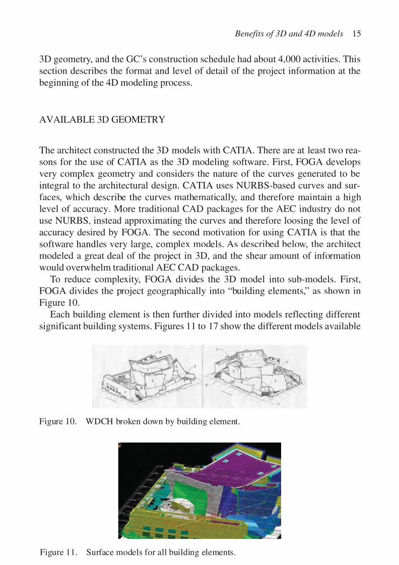
To reduce complexity, FOGA divides the 3D model into sub-models. First,
FOGA divides the project geographically into “building elements,” as shown inFigure 10.
Each building element is then further divided into models reflecting differentsignificant building systems. Figures 11 to 17 show the different models available
Benefits of 3D and 4D models 15
Figure 10. WDCH broken down by building element.
Figure 11. Surface models for all building elements.

7/14/2019 4DCAD and Visualization in Construction
http://slidepdf.com/reader/full/4dcad-and-visualization-in-construction-56327c6a084e9 25/296
16 M. Fischer et al.
Figure 13. Element 2 pattern model.
Figure 12. Element 2 surface model.
for building element 2. Figure 11 shows all of the building elements’ surface mod-els incorporated into one view. Figure 12 shows the surface model for element 2.The surface model contains everything that can be seen, from plaster, to glazing,to carpet, to wood panneling, etc. Figure 13 shows a pattern model. A pattern modeldescribes any pattern in an element that is relevant for architecture or construction.
7/14/2019 4DCAD and Visualization in Construction
http://slidepdf.com/reader/full/4dcad-and-visualization-in-construction-56327c6a084e9 26/296
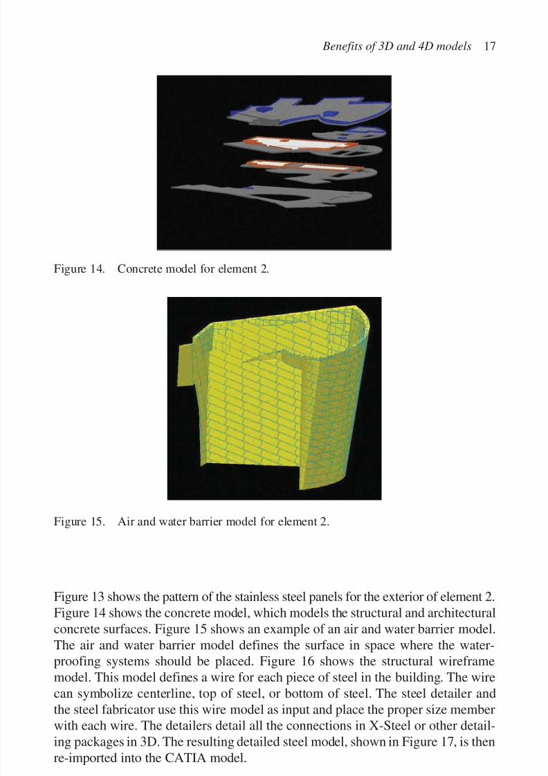
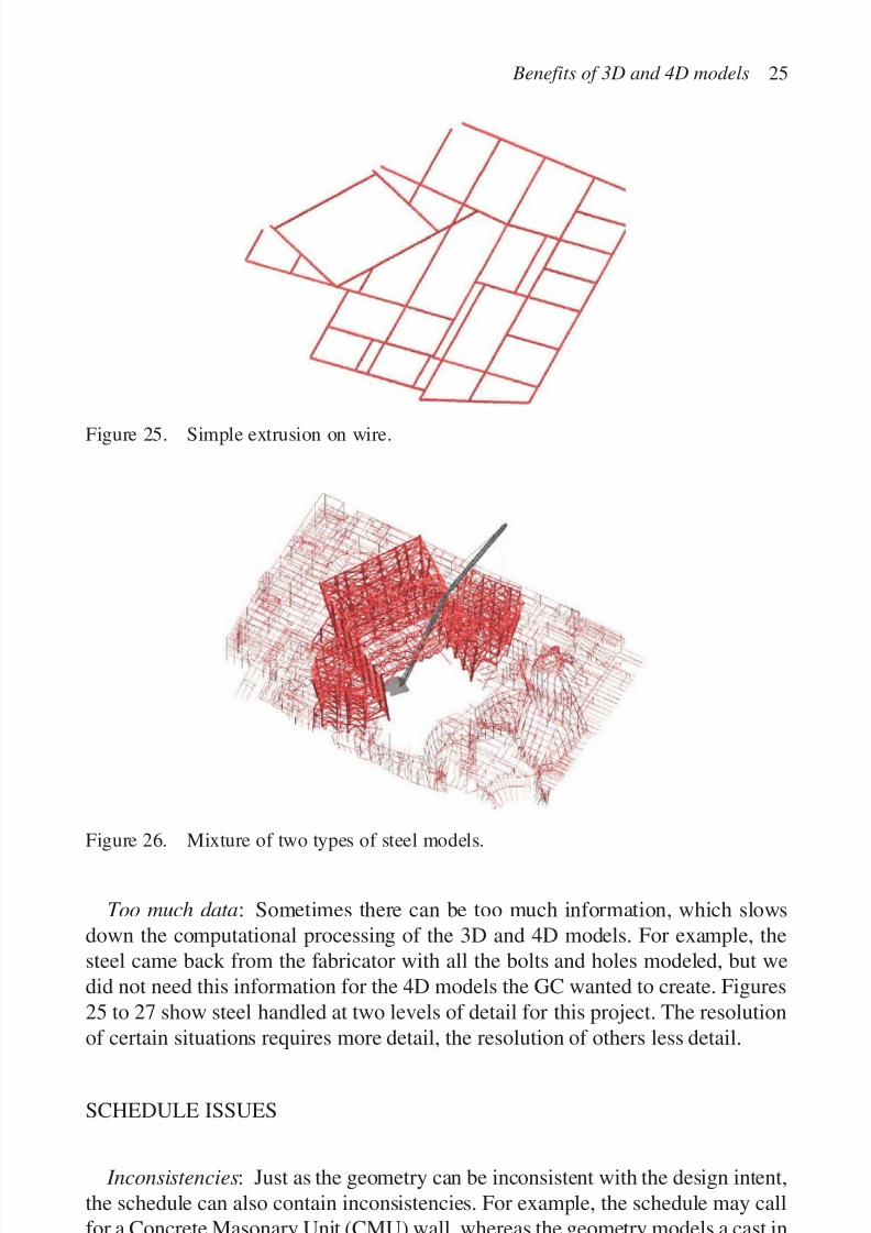
Figure 13 shows the pattern of the stainless steel panels for the exterior of element 2.Figure 14 shows the concrete model, which models the structural and architecturalconcrete surfaces. Figure 15 shows an example of an air and water barrier model.The air and water barrier model defines the surface in space where the water-
proofing systems should be placed. Figure 16 shows the structural wireframemodel. This model defines a wire for each piece of steel in the building. The wirecan symbolize centerline, top of steel, or bottom of steel. The steel detailer andthe steel fabricator use this wire model as input and place the proper size memberwith each wire. The detailers detail all the connections in X-Steel or other detail-ing packages in 3D. The resulting detailed steel model, shown in Figure 17, is thenre-imported into the CATIA model.
Benefits of 3D and 4D models 17
Figure 14. Concrete model for element 2.
Figure 15. Air and water barrier model for element 2.

7/14/2019 4DCAD and Visualization in Construction
http://slidepdf.com/reader/full/4dcad-and-visualization-in-construction-56327c6a084e9 27/296
18 M. Fischer et al.
Figure 16. Element 2 steel wireframe model.
Figure 17. Detailed steel model.
Each 3D model consists of layers reflecting different sub-systems. Table 2shows a partial listing of the layers. These layers are helpful for 4D modelingbecause they isolate certain scope information in the 3D model, which facilitatesthe identification of the appropriate geometric elements for a particular activity.However, frequently the layering organization is different from the organization of

7/14/2019 4DCAD and Visualization in Construction
http://slidepdf.com/reader/full/4dcad-and-visualization-in-construction-56327c6a084e9 28/296
the schedule, and the 4D modeler needs to reorganize the geometric informationfor the 4D model to fit the schedule organization (Fischer et al., 1998).
AVAILABLE SCHEDULE INFORMATION
The GC created the construction schedule with Primavera’s P3™ software. At thestart of the 4D modeling process in March 2000, the schedule contained about4,000 activities. By Fall 2000, the schedule consisted of approximately 7,200activities. The schedule divides the 3D project geometry into chunks that are rele-vant to an activity. Figure 18 shows the breakdown key for the activity ID in the
Benefits of 3D and 4D models 19
Table 2. A portion of the layer list.
Layer Layer LayerNo. CATIA layer contents No. CATIA layer contents No.
General project data (1 Thru 10) Stone (46 Thru 55)
1 Project grid 46 Vertical stone cladding 862 Column grid lines 47 Sloped stone cladding 873 Property line 48 Stone coping 884 Vacation envelope 49 Stone paving 895 Project reference geometry 50 Stone base 906 Project workpoints 51 Decomposed granite 917 CATIA construction geometry 52 Not used 928 Existing construction 53 Not used 93
54 Not used
Glazing assemblies (11 Thru 25) 55 Not used11 Skylight glazing Roof asssemblies (56 Thru 65) 9612 Sloped glazing 9713 Vertical glazing 56 Roof membrane Type 1 9814 Mullion wireframe (Center Line Mullion) 57 Roof membrane Type 2 9915 Mullion 58 Roof hatch 10016 Metal closure Trim 59 Roof drain 10117 Metal closure Panels 60 Stainless steel gutter 10218 Metal gutter 61 Expansion joint assembly 10319 Metal flashing 62 Roof davit pedestal 10420 Glazing anchor assembly 63 Roof assembly Type 3 10521 Glazing boundary 64 Not used 106
65 Not used 107Metal panel assemblies (26 Thru 45) 108
Miscellaneous exterior assemblies 10926 Metal panel assembly condition Type 1 11027 Metal panel assembly condition Type 2 66 Not used28 Metal panel assembly condition Type 3 67 Metal grill29 Metal panel assembly condition Type 4 68 Metal grating30 Metal panel assembly condition Type 5 69 Building maintenance equipment 12631 Metal panel assembly condition Type 6 70 Building maintenance track 127
32 Metal panel assembly air and 71 Stain less steel clad door 128water barrier

7/14/2019 4DCAD and Visualization in Construction
http://slidepdf.com/reader/full/4dcad-and-visualization-in-construction-56327c6a084e9 29/296
schedule. Activities are identified by building element, floor, area, and subarea,then by phase, system, component, and action. However, some activities do not fiteasily into this breakdown. For example, steel installers like to break the steel into
manageable chunks, called sequences, which are a grouping of steel that is self-supporting and can be erected in a reasonable amount of time. These sequencesoften span more than one building element, or cover more than one floor. Eventhough it was useful to have one main way to organize the schedule (as shown inFig. 18), many methods for decomposing the geometry and linking a scope of work to an activity are required to suit different types of work. Figure 19 shows
20 M. Fischer et al.
Figure 18. Activity code key for defining activities and relating them to the 3D model.
Figure 19. Organization of 3D model into levels, sequences and thirds.

7/14/2019 4DCAD and Visualization in Construction
http://slidepdf.com/reader/full/4dcad-and-visualization-in-construction-56327c6a084e9 30/296
Benefits of 3D and 4D models 21
the project broken into levels (red) and sequences (green). Figure 19 also showsthe main potion of the Concert Hall broken into thirds (blue) as the GC organizedsome of the work in the main hall in this way.
4D MODELING PROCESS AND 4D MODELS
Figure 20 maps the process for constructing the 4D models from the projectgeometry and schedule and shows the file formats used to translate between com-puter programs. Rhino3D™ proved to be very useful to import the NURBS-basedgeometry from CATIA, add names to the geometry, break up the geometry intorelevant configurations for the respective activities, and convert the geometries toVRML. Named geometrical elements allow a 4D modeler to match geometrynames to activity names quickly.
We built four 4D models for the project. Figures 21 to 24 show a screen shotfrom each of these models.
Figure 20. Process for constructing 4D models from 3D models and CPM schedules.

7/14/2019 4DCAD and Visualization in Construction
http://slidepdf.com/reader/full/4dcad-and-visualization-in-construction-56327c6a084e9 31/296
22 M. Fischer et al.
Figure 21. Steel, Concrete, and Exterior Enclosure model. This 4D model examines theoverall sequencing for the major structural and enclosure activities. It shows thesequencing of steel and of structural and architectural concrete. It includes metal decking,roofing, glazing, and enclosure systems, such as metal cladding assemblies including
secondary steel supports. Statistics: Number of 3D components: 340; Number of polygons: 515,000; Number of activities: 512.
Figure 22. Element 2 model. This 4D model goes into more detail for building element 2.It includes the interior work. The model includes interior stairs, elevators, fireproofing,and finishing systems. It shows mechanical and electrical activities by highlighting thefloor slabs in the area of work. Statistics: Number of 3D components: 105; Number of polygons: 85,000; Number of activities: 185.

7/14/2019 4DCAD and Visualization in Construction
http://slidepdf.com/reader/full/4dcad-and-visualization-in-construction-56327c6a084e9 32/296
Benefits of 3D and 4D models 23
Figure 23. Interior hall model. The interior of the Concert Hall is a highly congestedand complex space. All of the interior activities are squarely on the critical path. Themodel includes all the activities affecting this space: structural steel, concrete,plaster, wood finishes, mechanical, and electrical. The model also includes scaffolding.Statistics: Number of 3D components: 210; Number of polygons: 325,000; Number of activities: 667.
Figure 24. Detailed Hall Ceiling Model. In early 2001, we are constructing a fourthmodel to help with the detailed planning of the complex concert hall ceiling installation.Statistics: Number of 3D components: 180; Number of polygons: 520,000; Number of activities: to be determined.

7/14/2019 4DCAD and Visualization in Construction
http://slidepdf.com/reader/full/4dcad-and-visualization-in-construction-56327c6a084e9 33/296
CHALLENGES ENCOUNTERED WHILE BUILDING THE 4D MODELS
The construction of the models posed a number of challenges related to the geo-metry, the schedule, and the linking of the geometry and the schedule. In ourexperience, such issues are quite common during the development of 4D models,especially when the 3D models are created without knowledge of the needs for 4Dmodeling and construction planning. Another reason for these issues is that the con-struction of a 4D model requires significant project scope and schedule information.Some of this information is precisely the information that project participants wantto develop or refine through the 4D modeling process, and other information issimply not yet available because of resource or other constraints. A valuable contri-
bution of the 4D modeling process is that the process makes it very clear where com-plete scope and schedule information exists and where additional thinking is needed.
GEOMETRY ISSUES
Inconsistencies: The 3D models from the architect contained some inconsis-
tencies. For example, an object that was on the plaster layer should have been onthe gypsum board layer. Such inconsistencies create extra work during the linkingof the schedule and the 3D model because the 4D modeler cannot easily identify,isolate, and show the scope of work for a particular activity in 3D.
Lack of data: The surface model models only what is seen. In the case of awood wainscot on a plaster wall, FOGA modeled the plaster only where the woodwainscot does not cover it. Even though there is plaster under the wood wainscot,it is not modeled. Hence, in those areas, the surface model does not provide 3D
components that can be linked to activities. In addition, for some of the scope of work for steel erection the 3D models were also incomplete. The steel detailerstook the wire models from the architect, and produced detailed 3D models fromthese wires. This process was time-consuming, and at the time of 4D model con-struction, the detailers had detailed only some of the steel for the main concert hallbox. The rest of the steel had to have a 3D representation so that it could be seenduring 4D model simulation. We created an algorithm to hang a simple rectangu-lar shape on the wires to make the important information visible without over-
whelming the software or the user. Level of detail: Sometimes there is too little detail in the 3D model. The steel3D model came back from the steel fabricator all on one layer. However, onemight want to split primary and secondary steel into two activities, which wouldmake it necessary to have the primary and secondary steel on two layers. In addi-tion, FOGA modeled just the surfaces for the metal skin. A metal skin systemrequires backing support and clips, which were not modeled, but need to beinstalled, and should therefore be reflected in the 4D model.
24 M. Fischer et al.
7/14/2019 4DCAD and Visualization in Construction
http://slidepdf.com/reader/full/4dcad-and-visualization-in-construction-56327c6a084e9 34/296
Benefits of 3D and 4D models 25
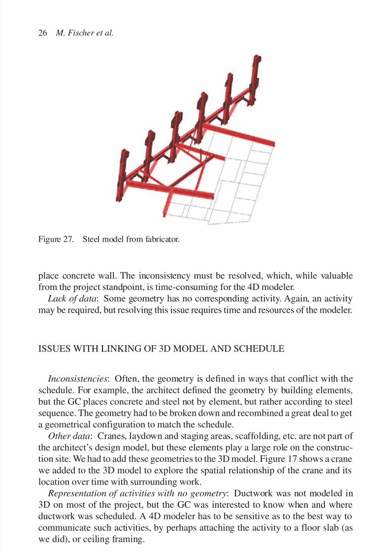
Figure 25. Simple extrusion on wire.
Figure 26. Mixture of two types of steel models.
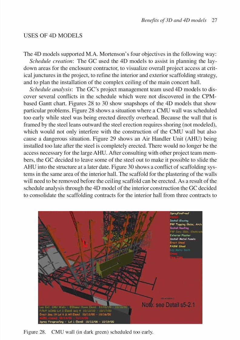
Too much data: Sometimes there can be too much information, which slowsdown the computational processing of the 3D and 4D models. For example, thesteel came back from the fabricator with all the bolts and holes modeled, but wedid not need this information for the 4D models the GC wanted to create. Figures25 to 27 show steel handled at two levels of detail for this project. The resolutionof certain situations requires more detail, the resolution of others less detail.
SCHEDULE ISSUES
Inconsistencies: Just as the geometry can be inconsistent with the design intent,the schedule can also contain inconsistencies. For example, the schedule may callfor a Concrete Masonary Unit (CMU) wall, whereas the geometry models a cast in
7/14/2019 4DCAD and Visualization in Construction
http://slidepdf.com/reader/full/4dcad-and-visualization-in-construction-56327c6a084e9 35/296
place concrete wall. The inconsistency must be resolved, which, while valuable
from the project standpoint, is time-consuming for the 4D modeler. Lack of data: Some geometry has no corresponding activity. Again, an activity
may be required, but resolving this issue requires time and resources of the modeler.
ISSUES WITH LINKING OF 3D MODEL AND SCHEDULE
Inconsistencies: Often, the geometry is defined in ways that conflict with theschedule. For example, the architect defined the geometry by building elements,but the GC places concrete and steel not by element, but rather according to steelsequence. The geometry had to be broken down and recombined a great deal to geta geometrical configuration to match the schedule.
Other data: Cranes, laydown and staging areas, scaffolding, etc. are not part of the architect’s design model, but these elements play a large role on the construc-tion site. We had to add these geometries to the 3D model. Figure 17 shows a crane
we added to the 3D model to explore the spatial relationship of the crane and itslocation over time with surrounding work. Representation of activities with no geometry: Ductwork was not modeled in
3D on most of the project, but the GC was interested to know when and whereductwork was scheduled. A 4D modeler has to be sensitive as to the best way tocommunicate such activities, by perhaps attaching the activity to a floor slab (aswe did), or ceiling framing.
26 M. Fischer et al.
Figure 27. Steel model from fabricator.
7/14/2019 4DCAD and Visualization in Construction
http://slidepdf.com/reader/full/4dcad-and-visualization-in-construction-56327c6a084e9 36/296
USES OF 4D MODELS
The 4D models supported M.A. Mortenson’s four objectives in the following way:Schedule creation: The GC used the 4D models to assist in planning the lay-
down areas for the enclosure contractor, to visualize overall project access at crit-ical junctures in the project, to refine the interior and exterior scaffolding strategy,and to plan the installation of the complex ceiling of the main concert hall.
Schedule analysis: The GC’s project management team used 4D models to dis-cover several conflicts in the schedule which were not discovered in the CPM-based Gantt chart. Figures 28 to 30 show snapshops of the 4D models that showparticular problems. Figure 28 shows a situation where a CMU wall was scheduled
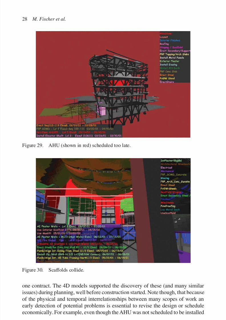
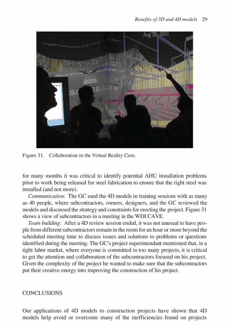
too early while steel was being erected directly overhead. Because the wall that isframed by the steel leans outward the steel erection requires shoring (not modeled),which would not only interfere with the construction of the CMU wall but alsocause a dangerous situation. Figure 29 shows an Air Handler Unit (AHU) beinginstalled too late after the steel is completely erected. There would no longer be theaccess necessary for the large AHU. After consulting with other project team mem-bers, the GC decided to leave some of the steel out to make it possible to slide theAHU into the structure at a later date. Figure 30 shows a conflict of scaffolding sys-
tems in the same area of the interior hall. The scaffold for the plastering of the wallswill need to be removed before the ceiling scaffold can be erected. As a result of theschedule analysis through the 4D model of the interior construction the GC decidedto consolidate the scaffolding contracts for the interior hall from three contracts to
Benefits of 3D and 4D models 27
Figure 28. CMU wall (in dark green) scheduled too early.
7/14/2019 4DCAD and Visualization in Construction
http://slidepdf.com/reader/full/4dcad-and-visualization-in-construction-56327c6a084e9 37/296
one contract. The 4D models supported the discovery of these (and many similarissues) during planning, well before construction started. Note though, that becauseof the physical and temporal interrelationships between many scopes of work anearly detection of potential problems is essential to revise the design or scheduleeconomically. For example, even though the AHU was not scheduled to be installed
28 M. Fischer et al.
Figure 30. Scaffolds collide.
Figure 29. AHU (shown in red) scheduled too late.
7/14/2019 4DCAD and Visualization in Construction
http://slidepdf.com/reader/full/4dcad-and-visualization-in-construction-56327c6a084e9 38/296
for many months it was critical to identify potential AHU installation problemsprior to work being released for steel fabrication to ensure that the right steel wasinstalled (and not more).
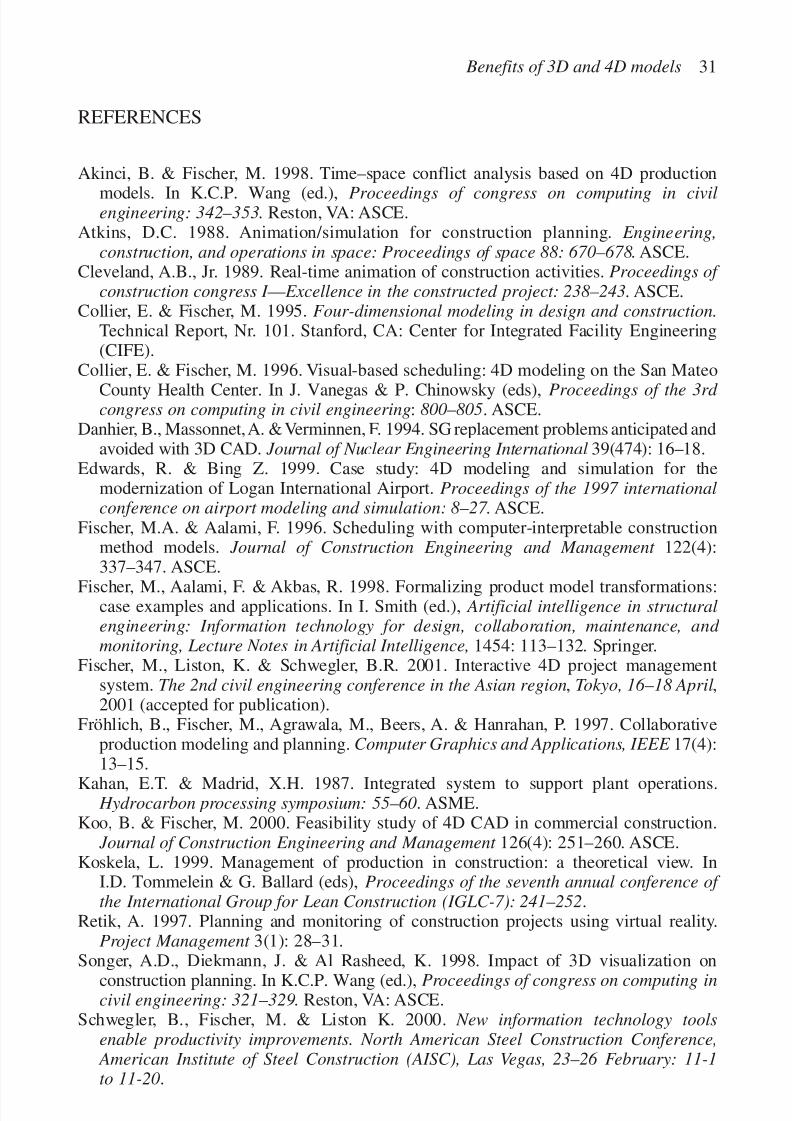
Communication: The GC used the 4D models in training sessions with as manyas 40 people, where subcontractors, owners, designers, and the GC reviewed themodels and discussed the strategy and constraints for erecting the project. Figure 31shows a view of subcontractors in a meeting in the WDI CAVE.
Team building: After a 4D review session ended, it was not unusual to have peo-ple from different subcontractors remain in the room for an hour or more beyond thescheduled meeting time to discuss issues and solutions to problems or questionsidentified during the meeting. The GC’s project superintendant mentioned that, in atight labor market, where everyone is committed to too many projects, it is criticalto get the attention and collaboration of the subcontractors focused on his project.Given the complexity of the project he wanted to make sure that the subcontractorsput their creative energy into improving the construction of his project.
CONCLUSIONS
Our applications of 4D models to construction projects have shown that 4Dmodels help avoid or overcome many of the inefficiencies found on projects
Benefits of 3D and 4D models 29
Figure 31. Collaboration in the Virtual Reality Cave.

7/14/2019 4DCAD and Visualization in Construction
http://slidepdf.com/reader/full/4dcad-and-visualization-in-construction-56327c6a084e9 39/296
today: congestion, out of sequence work, multiple stops and starts, inability todo detailed planning in advance, obstructions due to material stocks, etc.(Koskela, 1999). In all cases except on the Sequus Pharmaceuticals, the
Experience Music Project, and the WDCH, the 4D modeling effort required theconstruction of a separate 3D model because the design had been done in 2D, orthe 3D models were not up to date or incompatible with the 4D modeling tools.The schedule information could be used as it was, but often the project teamdecided to make the activities more detailed to see more detail in the 4D model.As can be seen from Table 1, for many of the benefits the generator of the infor-mation necessary for 4D modeling is not the same party realizing the benefits of 4D modeling. Hence, the realization of the benefits of 4D models on projects witha traditional design-bid-build approach often requires extra modeling work.However, the benefits a GC or a subcontractor can realize from 4D modelsstill often outweigh the cost of building the necessary CAD models. On theSequus project the owner avoided this extra work by awarding a design-buildcontract to a team consisting of Flad & Associates (architect), Hathaway-Dinwiddie(GC), Rosendin Electric, Paragon Mechanical, and Rountree Plumbing. Thismaximized the opportunity for each party to enter and maintain the information inthe 3D CAD model necessary to realize the benefits. In summary, 4D modelsallow project stakeholders to work out many design and construction issues in the
computer model before actual construction, maximizing project value to ownersand making it more likely that the project will be completed as planned anddesigned.
ACKNOWLEDGMENTS
We are indebted to many professionals and students who have been instrumentalin making our 4D modeling efforts successful. We would like to acknowledge thefollowing people in particular: Buddy Cleveland, Jerry King and Kent Simons forthe technology support over the years; Jack Ritter, Tom Trainor and GeorgeHurley for getting us started on the San Mateo County Health Center; ToddZabelle and Greg Silling for sharing construction insights with us over the years;Melody Spradlin and everyone else from the Sequus project for going live; Jim
Glymph, Kristin Woehl, and Dennis Sheldon from FOGA for the challenge, funand excitement of applying 4D models on FOGA projects; Chris Raftery for let-ting us participate in EMP and Lisa Wickwire for keeping us current with projectinformation on EMP; Ben Schwegler from WDI for his substantial financial andintellectual support and for co-hosting the workshop; and Greg Knutson, Derek Cunz, Jim Yowan, David Mortenson, David Aquilera, and Joe Patterson on theWDCH.
30 M. Fischer et al.
7/14/2019 4DCAD and Visualization in Construction
http://slidepdf.com/reader/full/4dcad-and-visualization-in-construction-56327c6a084e9 40/296
REFERENCES
Akinci, B. & Fischer, M. 1998. Time–space conflict analysis based on 4D production
models. In K.C.P. Wang (ed.), Proceedings of congress on computing in civilengineering: 342–353. Reston, VA: ASCE.
Atkins, D.C. 1988. Animation/simulation for construction planning. Engineering,construction, and operations in space: Proceedings of space 88: 670–678. ASCE.
Cleveland, A.B., Jr. 1989. Real-time animation of construction activities. Proceedings of construction congress I — Excellence in the constructed project: 238–243. ASCE.
Collier, E. & Fischer, M. 1995. Four-dimensional modeling in design and construction.Technical Report, Nr. 101. Stanford, CA: Center for Integrated Facility Engineering(CIFE).
Collier, E. & Fischer, M. 1996. Visual-based scheduling: 4D modeling on the San Mateo
County Health Center. In J. Vanegas & P. Chinowsky (eds), Proceedings of the 3rd congress on computing in civil engineering: 800–805. ASCE.
Danhier, B., Massonnet,A. & Verminnen, F. 1994. SG replacement problems anticipated andavoided with 3D CAD. Journal of Nuclear Engineering International 39(474): 16–18.
Edwards, R. & Bing Z. 1999. Case study: 4D modeling and simulation for themodernization of Logan International Airport. Proceedings of the 1997 internationalconference on airport modeling and simulation: 8–27 . ASCE.
Fischer, M.A. & Aalami, F. 1996. Scheduling with computer-interpretable constructionmethod models. Journal of Construction Engineering and Management 122(4):337–347. ASCE.
Fischer, M., Aalami, F. & Akbas, R. 1998. Formalizing product model transformations:case examples and applications. In I. Smith (ed.), Artificial intelligence in structuralengineering: Information technology for design, collaboration, maintenance, and monitoring, Lecture Notes in Artificial Intelligence, 1454: 113–132. Springer.
Fischer, M., Liston, K. & Schwegler, B.R. 2001. Interactive 4D project managementsystem. The 2nd civil engineering conference in the Asian region, Tokyo, 16–18 April,2001 (accepted for publication).
Fröhlich, B., Fischer, M., Agrawala, M., Beers, A. & Hanrahan, P. 1997. Collaborativeproduction modeling and planning. Computer Graphics and Applications, IEEE 17(4):
13–15.Kahan, E.T. & Madrid, X.H. 1987. Integrated system to support plant operations. Hydrocarbon processing symposium: 55–60. ASME.
Koo, B. & Fischer, M. 2000. Feasibility study of 4D CAD in commercial construction. Journal of Construction Engineering and Management 126(4): 251–260. ASCE.
Koskela, L. 1999. Management of production in construction: a theoretical view. InI.D. Tommelein & G. Ballard (eds), Proceedings of the seventh annual conference of the International Group for Lean Construction (IGLC-7): 241–252.
Retik, A. 1997. Planning and monitoring of construction projects using virtual reality.Project Management 3(1): 28–31.
Songer, A.D., Diekmann, J. & Al Rasheed, K. 1998. Impact of 3D visualization onconstruction planning. In K.C.P. Wang (ed.), Proceedings of congress on computing incivil engineering: 321–329. Reston, VA: ASCE.
Schwegler, B., Fischer, M. & Liston K. 2000. New information technology toolsenable productivity improvements. North American Steel Construction Conference, American Institute of Steel Construction (AISC), Las Vegas, 23–26 February: 11-1to 11-20.
Benefits of 3D and 4D models 31

7/14/2019 4DCAD and Visualization in Construction
http://slidepdf.com/reader/full/4dcad-and-visualization-in-construction-56327c6a084e9 41/296
Staub, S., Fischer, M. & Spradlin, M. 1999. Into the fourth dimension. Civil Engineering69(5): 44–47. ASCE.
Vaugn, F. 1996. 3D and 4D CAD modeling on commercial design-build projects.Proceedings of computing in civil engineering congress: 390–396 . ASCE.
Williams, M. 1996. Graphical simulation for project planning: 4D-Planner™.Proceedings of computing in civil engineering congress: 404–409. ASCE.
32 M. Fischer et al.

7/14/2019 4DCAD and Visualization in Construction
http://slidepdf.com/reader/full/4dcad-and-visualization-in-construction-56327c6a084e9 42/296
BEYOND SPHERELAND: 4D CAD IN CONSTRUCTIONCOMMUNICATIONS
Dennis Fukai
M.E. Rinker, Sr. School of Building Construction,
University of Florida, Gainesville, FL, USA
33
Abstract
This study examines the fourth dimension as the product of a fundamental shift in a para-
digmatic world view. This shift changes the normal way of “seeing” or visualizing the
obviousness of the context of our everyday practices and leads in a different direction with
a completely new vision of the processes antiquated by its transformation. This can beseen in the renaissance of closely held ideas that occurred in the change from an oral tra-
dition to descriptive diagram, from diagram to written and reproducible text and two-
dimensional images, and from simple image to perspective drawings and photographs.
These are “visionary” changes that triggered immediate and lasting displacements in our
social and technical development.
The shift from three to four dimensions in computer aided design (CAD) does not seem
to have had this revolutionary impact even though its value and potential have been made
quite clear by a number of researchers. As a consequence, this study explores the context of
these new computational tools and how they might be used to enhance the communicationprocess in construction. It suggests that computer mediated communications in construc-
tion might be better used to understand the process delineated by a model’s construction,
where that model is developed as a preview of its construction, “built” according to the same
methods and techniques anticipated in the actual project.
Keywords: computer, visual, communications, construction, modeling
INTRODUCTION: “UPWARD, YET NOT NORTHWARD”
In the 1880s, Edwin Abbott wrote a classic book about the idea of dimensions thathas been reprinted more than six times (Abbott, 1952). Abbott was a schoolteacherwriting about a society of objects that inhabited a land he called Flatland. There

7/14/2019 4DCAD and Visualization in Construction
http://slidepdf.com/reader/full/4dcad-and-visualization-in-construction-56327c6a084e9 43/296
were no solids in Flatland. Instead, objects existed in two dimensions and wereviewed along their edge. This means geometric shapes had lengths and widths,but because they had no height, they always looked like a line. As shown inFigure 1, this is much like a circle first standing on its edge so you can see its three-dimensional face and then laid flat on a table so that only the edge is visible. Unableto rise above this edge view meant circles always appear as a line in Flatland.
This also meant that a square and a circle looked the same. To “see” the differ-ence, one had to feel the edge of an object to know whether it had corners orcurves. There was an educated class of citizens in Flatland that could distinguishthose shapes without touching them because their eyes had been trained to seethe object’s outer edge fade slightly into a fog or haze. However, ordinary peopledid not have the skill to visualize this subtle shift in dimension.
“Space” was therefore flat on a two-dimensional plane and measured in thedirection of the length and width of the edge of an object. This meant objects could
move north, east, south, and west according to two axis, but it took great skill anda fundamental understanding of the nature of this two-dimensional “space” tomove around. Abbott notes there was a “southward” attraction that could be felt insome regions of the plane, but since the edge of an object was always a line, anyview of distance had no perspective. In other words, an object could be near or far,polygon or curved, or open or closed, as one moved from place to place. Everythinglooked the same and it took education and training to read two dimensions andunderstand the subtle variations of the forms it contained in order to navigate with-
out getting lost.A sphere called the “stranger” came into Flatland. When it arrived, it intro-
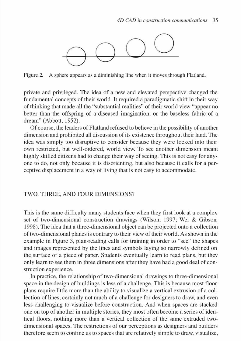
duced another dimension: up and down. From the Flatlander’s point of view, asphere moving up and down through the edge view of the two-dimensional sur-face of Flatland appeared as a line that grows shorter and shorter until it disap-pears. This meant that a three-dimensional object like a sphere might look like anyother circle or square, but it could actually rise above its two-dimensional planeand disappear as illustrated in Figure 2. No other object in the world view of
Flatlanders could shrink, stretch, or disappear in and out of its restricted two-dimensional view like a three-dimensional object.Even more amazing to the inhabitants of Flatland, was that the very notion of
up and down meant that things that were once secret or hidden when viewed fromtheir edge were now exposed when viewed from “above.” This meant the inside of a two-dimensional circle could be seen from this other dimension. Anyone able tosee in this new dimension could therefore see things that were once considered
34 D. Fukai
Figure 1. A circle appears as a line when you live in Flatland.
7/14/2019 4DCAD and Visualization in Construction
http://slidepdf.com/reader/full/4dcad-and-visualization-in-construction-56327c6a084e9 44/296
private and privileged. The idea of a new and elevated perspective changed thefundamental concepts of their world. It required a paradigmatic shift in their wayof thinking that made all the “substantial realities” of their world view “appear nobetter than the offspring of a diseased imagination, or the baseless fabric of adream” (Abbott, 1952).
Of course, the leaders of Flatland refused to believe in the possibility of anotherdimension and prohibited all discussion of its existence throughout their land. Theidea was simply too disruptive to consider because they were locked into theirown restricted, but well-ordered, world view. To see another dimension meanthighly skilled citizens had to change their way of seeing. This is not easy for any-one to do, not only because it is disorienting, but also because it calls for a per-ceptive displacement in a way of living that is not easy to accommodate.
TWO, THREE, AND FOUR DIMENSIONS?
This is the same difficulty many students face when they first look at a complexset of two-dimensional construction drawings (Wilson, 1997; Wei & Gibson,1998). The idea that a three-dimensional object can be projected onto a collection
of two-dimensional planes is contrary to their view of their world. As shown in theexample in Figure 3, plan-reading calls for training in order to “see” the shapesand images represented by the lines and symbols laying so narrowly defined onthe surface of a piece of paper. Students eventually learn to read plans, but theyonly learn to see them in three dimensions after they have had a good deal of con-struction experience.
In practice, the relationship of two-dimensional drawings to three-dimensionalspace in the design of buildings is less of a challenge. This is because most floor
plans require little more than the ability to visualize a vertical extrusion of a col-lection of lines, certainly not much of a challenge for designers to draw, and evenless challenging to visualize before construction. And when spaces are stackedone on top of another in multiple stories, they most often become a series of iden-tical floors, nothing more than a vertical collection of the same extruded two-dimensional spaces. The restrictions of our perceptions as designers and builderstherefore seem to confine us to spaces that are relatively simple to draw, visualize,
4D CAD in construction communications 35
Figure 2. A sphere appears as a diminishing line when it moves through Flatland.

7/14/2019 4DCAD and Visualization in Construction
http://slidepdf.com/reader/full/4dcad-and-visualization-in-construction-56327c6a084e9 45/296
36 D. Fukai
F i g u r e 3 .
I t t a k e s
e x p e r i e n c e t o s e e i n t h r e e d i m e n s i o n s .

7/14/2019 4DCAD and Visualization in Construction
http://slidepdf.com/reader/full/4dcad-and-visualization-in-construction-56327c6a084e9 46/296
and build. There are exceptions, but when the imagination of an architect or engineerproduces something more complex and three-dimensional than the ordinary, theresult is difficult to understand and usually more costly to build. The variation
from the norm requires a higher level of interpretation and the result can be at oncedisturbing and exciting.This odd perceptive shift from three to two and back to three dimensions also
constrains the potential of the buildings that we build. A designer imagines spacein three dimensions, but then must translate that space to two and the builder mustthen take the two-dimensional drawings and transform the lines back to the thirddimension.
FOUR DIMENSIONS AND MORE INFORMATION?
This becomes even more disorienting when we introduce the idea of a fourthdimension. Now computers automate much of the information found on a two-dimensional drawing. For some, any computer aided drawing (CAD) introducesa fourth dimension when it is correlated with computer-generated data not nor-mally found in hand drawings (Wright, 1994; Vaugn, 1996; Cardone et al., 1999).
However, others point to the obvious flaws in the assumption of this dimensionalshift when applied to CAD documents (Shah & Wilson, 1988). If information is abroad category of “stuff” or “chunks,” it can in itself describe multiple dimensionsof perception (Hofstadter, 1980). In the same way, written descriptions, perhapsassociated with two-dimensional diagrams, can bridge multiple dimensions in away that only a writer can describe. It follows then that a construction document,with the addition of a description or sequential representation that was alreadyinherent in that document, does not necessarily approach a true fourth dimension
(Shah & Wilson, 1988; Falcioni, 1999). For example, it is hard to argue that a timesequence image of two-dimensional images shown in Figure 4 represents three orfour dimensions.
Similarly, by associating the two-dimensional symbols for chairs, desks, lamps,and credenzas as informational “Blocks” in a CAD program, a furniture layoutcan be made to automatically sort, count, and list the quantities of the objects thathave been inserted into the two-dimensional plan. Is this three or four dimensions?
Of course, the apparently flat furniture plan has a very important third dimen-
sion. Walking through the spaces before the installations would show verticaldimensions of counters, furnishings, equipment, steps and stairs, and the height onthe walls where signs, clocks, or coat racks are to be placed. There is no doubt thatthe representation of three-dimensional space and its associated information arewell served by the automated references that can be generated by a database, how-ever, it begs the question: do two-dimensional diagrams and symbols representthree-dimensional objects with the automated data defining a third dimension?
4D CAD in construction communications 37

7/14/2019 4DCAD and Visualization in Construction
http://slidepdf.com/reader/full/4dcad-and-visualization-in-construction-56327c6a084e9 47/296
Most would agree that a two-dimensional diagram of a three-dimensional spaceis not in itself three-dimensional. A three-dimensional document must be drawn inthree dimensions to visually break from a two-dimensional plane (Wei & Gibson,1998). After all, there are no true vertical relationships in the average extruded
floor plan, and furniture installations can most often be completed with no specialvisualization skills. In practice, the actual construction may not even follow theoriginal plan, primarily because placement will be adjusted according to the wayobjects “fit” within the assembly. The perceptive reality of the plan will thereby beignored once its diagrammatic representation is over shadowed by the actualspace. In other words, once we see the real thing, everything else is a “baselessfabric of a dream” (Abbott, 1952).
With the introduction of 3D CAD programs, construction models can now be
built to meet this same perceptive challenge (LaCourse, 1990). These are modelsassembled from the three-dimensional pieces of a total structure. As shown inFigure 5, the combination of the assembly of a building as solids and the ability toview these solids from many viewpoints greatly enhances a constructor’s under-standing of spatial relationships, construction details, and fabrication techniques.
At the same time, it is difficult to actually construct an object from a three-dimensional model even though, as shown in Figure 6, annotations can be added toexplain the construction. This is because details about materials, dimensions, andspecifications are still required to build the object on a construction site. To meetthis challenge, some innovative practitioners have begun to use three-dimensionalmodels to create two-dimensional drawings (Wilson, 1997). In AutoCAD2000,operators can use “layouts” to convert models to two-dimensional diagrams,annotate and dimension them for use in the actual construction. The perceptiveshift to a three-dimensioned construction model therefore reverts by default to thestandard two-dimensional drawing.
38 D. Fukai
Figure 4. Three phases for the installation of concrete in a runway constructionrepresent four dimensions.

7/14/2019 4DCAD and Visualization in Construction
http://slidepdf.com/reader/full/4dcad-and-visualization-in-construction-56327c6a084e9 48/296
4D CAD in construction communications 39
Figure 5. Three-dimensional models bridge the perceptive gap left by two-dimensionaldrawings.
Figure 6. Three-dimensional models can be annotated, but it is difficult to show thekinds of layout dimensions necessary for actual construction.
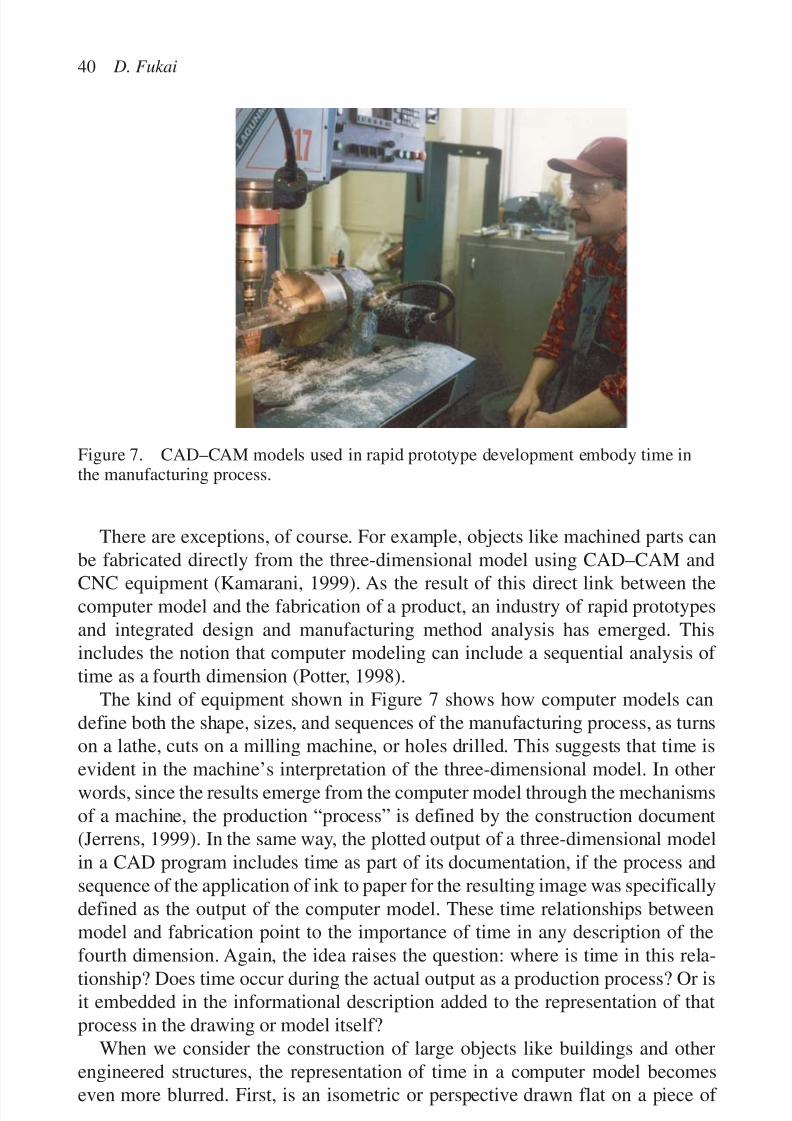
7/14/2019 4DCAD and Visualization in Construction
http://slidepdf.com/reader/full/4dcad-and-visualization-in-construction-56327c6a084e9 49/296
There are exceptions, of course. For example, objects like machined parts canbe fabricated directly from the three-dimensional model using CAD–CAM and
CNC equipment (Kamarani, 1999). As the result of this direct link between thecomputer model and the fabrication of a product, an industry of rapid prototypesand integrated design and manufacturing method analysis has emerged. Thisincludes the notion that computer modeling can include a sequential analysis of time as a fourth dimension (Potter, 1998).
The kind of equipment shown in Figure 7 shows how computer models candefine both the shape, sizes, and sequences of the manufacturing process, as turnson a lathe, cuts on a milling machine, or holes drilled. This suggests that time is
evident in the machine’s interpretation of the three-dimensional model. In otherwords, since the results emerge from the computer model through the mechanismsof a machine, the production “process” is defined by the construction document(Jerrens, 1999). In the same way, the plotted output of a three-dimensional modelin a CAD program includes time as part of its documentation, if the process andsequence of the application of ink to paper for the resulting image was specificallydefined as the output of the computer model. These time relationships betweenmodel and fabrication point to the importance of time in any description of the
fourth dimension. Again, the idea raises the question: where is time in this rela-tionship? Does time occur during the actual output as a production process? Or isit embedded in the informational description added to the representation of thatprocess in the drawing or model itself?
When we consider the construction of large objects like buildings and otherengineered structures, the representation of time in a computer model becomeseven more blurred. First, is an isometric or perspective drawn flat on a piece of
40 D. Fukai
Figure 7. CAD–CAM models used in rapid prototype development embody time inthe manufacturing process.

7/14/2019 4DCAD and Visualization in Construction
http://slidepdf.com/reader/full/4dcad-and-visualization-in-construction-56327c6a084e9 50/296
paper or visible on a computer screen three-dimensional? And if “chunks” of information are added to the isometric drawings can it be said that this informa-tion represents another dimension? It seems logical that the result is simply an
extension of the same information that was already resident in the drawing. Whythen is the addition of time, in a similar image or visual composition, not simplyanother informational layer? How does time extend the underlying model into arevolutionary fourth dimension?
TIME AS A DIMENSION
Defining the fourth dimension is a matter of dimensional relativity. Abbott won-dered if the fourth dimension had anything to do with an unseen axis in three-dimensional space. He saw a mathematical progression. If a non-dimensional “point”has a single point, a one-dimensional “line” has two points, a two-dimensional“square” has four points, and a three-dimensional “cube” has eight points; thenthe fourth dimension might be some extension of an object with 16 points. Abbottthought that within the perceptive paradigm of three-dimensional space the fourthdimension might be something he called “extra-solids” produced by “motion of
the solids” and “double-extra solids” that result from the “motion of the extra-solidsthrough space.”
This analogy of solids in motion through space is interesting when we considerthat Abbott was writing these words when Einstein was a child, and space andtime relationships remained to be hypothesized and tested as a theory of relatively.It was with Einstein’s work that the idea of a three-dimensional world took on thefourth dimension of time. For Einstein, objects no longer simply exist as solids,instead they were part of a continuum of time, perpendicular to the space created
by the juxtaposition of the mass of that object. Time is thereby measured by themovement of light and is affected or changed by mass to produce a series of “relativities” defined by the position of the observer.
Non-physicists have taken the notion of time as the fourth dimension and usedtime in its simplest form to describe a sequence of passing events or phases. In thisinterpretation, time can be as simple as a series of photographs that capture a par-ticular event. However, this does not seem like an elegant interpretation of thefourth dimension. Are a series of photos showing a sequential event in Figure 8,
four-dimensional?Time can also be shown in a series of model images as the phases of an object’sproduction, operation, deterioration, and/or maintenance (see Fig. 9). In thismodel, “time” is embedded as a representation of the “motion” of an object inspace. The result is that the fourth dimension in CAD has come to be understoodas the visual representation of time in the form of images of the phases of theevolution of a three-dimensional model. Others argue we cross the threshold of a
4D CAD in construction communications 41

7/14/2019 4DCAD and Visualization in Construction
http://slidepdf.com/reader/full/4dcad-and-visualization-in-construction-56327c6a084e9 51/296
42 D. Fukai
Figure 8. A sequential series of photographs as a four-dimensional image.
Figure 9. Time as the fourth dimension of a three-dimensional model.

7/14/2019 4DCAD and Visualization in Construction
http://slidepdf.com/reader/full/4dcad-and-visualization-in-construction-56327c6a084e9 52/296
fifth dimension when layers of information are added to a four-dimensional model(Cardone et al., 1999).
When we think of the complexity of Einstein’s theory, the idea that time can be
represented in a three-dimensional model as the sequence or phases of a construc-tion, does not seem to reach its full potential. After all, his theory is that thespace–time relationship of the fourth dimension is affected by the mass of the solids.In fact, the energy produced by the relationship of mass and time is a derivative of this relationship. This means that the presence of the solid object must distort andconstrain time according to the point of view of the observer. Accordingly, thespace–time dimension is a continuum that includes the observer; it is the relativeposition of the observer within this continuum that defines the perceptive shift inthat person’s view of both time and space.
It could be said that a sequential series of three-dimensional images are nothingmore than additional information about the same three-dimensional object, evenwhen the motion associated with the sequence discloses a new perspective(Yamaguchi & Liu, 1998). Time existed or could have existed in the originalimage as an annotation, it is only its interpretation or visual representation that hasbeen enhanced. This of course includes notes about movement, flow, and events,past or imagined, of the actual object in a photograph or its representation in three-dimensional space.
It seems then that relationship of time and space in 4D CAD may therefore playto the immediate application of sequential modeling without looking to its fullpotential. There is no doubt that understanding the evolution of an object, eitherto document its construction or to visualize some aspect of the design, is important,however, this may be a narrow view of a larger space–time relationship.
ONWARD THROUGH THE FOG
Perhaps the fourth dimension is not northward or upward, but onward through thefog of uncertainty. Consider that if the relative position of the observer in aspace–time continuum changes the perceptive results of both space and time forthat observer, the true fourth dimension may depend on how the observer visual-izes changes in the model over time. This would make change important in under-standing the continuum of these dimensional boundaries.
This is evident in the work of a number of researchers. For example, the Centerfor Integrated Facility Engineering (CIFE) used a construction method model(CMM) and expanded it into something called “Collaborative 4D CAD” (Aalami& Fischer, 1998). A CMM is a variation on a phased model that is used to analyzethe construction process through visualization. It asserts the inclusion of a fourthdimension because its CMM analysis focuses on a process that relates planningand management decisions directly to the sequence of the building’s construction.
4D CAD in construction communications 43

7/14/2019 4DCAD and Visualization in Construction
http://slidepdf.com/reader/full/4dcad-and-visualization-in-construction-56327c6a084e9 53/296
Collaborative 4D CAD is a variation of this analytical model in that it includes thescheduling requirements and milestones which may change or constrain the con-struction process (McKinney et al., 1996). Its goal is to establish a “common
ground” on which all designers can interact and enable them to better understandthe design intent. This has been explored in a number of other variations in otherdisciplines (LaCourse, 1990; Potter, 1998; Johnson, 1999).
In construction, interactive 4D CAD represents time as a schedule tied to sequen-tial variations of a single representational model. In other words, the information ona schedule is correlated to the information in a CAD model to help visualize asequence of events. The magic of this idea is that the model can be presented as asequence of assemblies that directly parallel the critical points on the schedule. Intheory, the model could be layered into a very detailed animation that would simu-late the total construction, or at least one view of that construction.
Of course, time-related visualization also includes the design, planning, andconstruction processes defined in Gantt charts, PERT diagrams, and/or CPMschedules. These diagrams abstract time as scaled lines and informational nodes, butdo not always represent those abstractions with an image of the object’s construc-tion. Instead, the image is implied through technical references to the constructiondocuments. The image of the object is therefore resident in a schedule when inter-preted by a trained and experienced “eye”. After all, construction managers have
had to associate schedules with construction drawings and specifications in orderto make the decisions required to build their projects for a very long time.
With this in mind, if we build a three-dimensional model to represent the finaldesign of an object and we learn to move around that object in a virtual space,it seems logical to assume that we have bridged the perceptive gap of a two-dimensional diagram. There can be little argument against the perceptive value of a three-dimensional model. In fact, for those that can use the computer to con-struct these models, we know that immersion in this virtual environment can be
an approximation of the real world (Johnshon, 1999; McKinney et al., 1999).However, the absence of motion and movement that were part of the model’s con-struction are not clearly represented in the three-dimensional form. In the end, onewonders if this embodied time and motion might be a prelude to the constructionprocess (LaCourse, 1990; Kamarani, 1999).
THE CURVATURE IN TIME–SPACE FROM AN IMMERSIVE
POINT OF VIEW
The potential of improving project production and assisting managers in makingdecisions by helping them visualize and simulate a construction seems clear, butis there a deeper level of insight that might be derived from modeling space andtime? For example, in a recent experiment with students at the M. E. Rinker,
44 D. Fukai
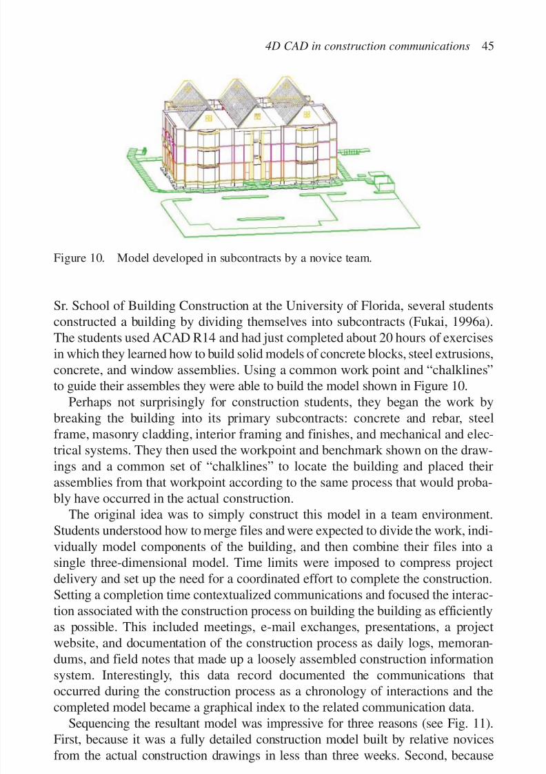
7/14/2019 4DCAD and Visualization in Construction
http://slidepdf.com/reader/full/4dcad-and-visualization-in-construction-56327c6a084e9 54/296
Sr. School of Building Construction at the University of Florida, several studentsconstructed a building by dividing themselves into subcontracts (Fukai, 1996a).The students used ACAD R14 and had just completed about 20 hours of exercisesin which they learned how to build solid models of concrete blocks, steel extrusions,concrete, and window assemblies. Using a common work point and “chalklines”to guide their assembles they were able to build the model shown in Figure 10.
Perhaps not surprisingly for construction students, they began the work bybreaking the building into its primary subcontracts: concrete and rebar, steelframe, masonry cladding, interior framing and finishes, and mechanical and elec-trical systems. They then used the workpoint and benchmark shown on the draw-ings and a common set of “chalklines” to locate the building and placed theirassemblies from that workpoint according to the same process that would proba-bly have occurred in the actual construction.
The original idea was to simply construct this model in a team environment.
Students understood how to merge files and were expected to divide the work, indi-vidually model components of the building, and then combine their files into asingle three-dimensional model. Time limits were imposed to compress projectdelivery and set up the need for a coordinated effort to complete the construction.Setting a completion time contextualized communications and focused the interac-tion associated with the construction process on building the building as efficientlyas possible. This included meetings, e-mail exchanges, presentations, a projectwebsite, and documentation of the construction process as daily logs, memoran-
dums, and field notes that made up a loosely assembled construction informationsystem. Interestingly, this data record documented the communications thatoccurred during the construction process as a chronology of interactions and thecompleted model became a graphical index to the related communication data.
Sequencing the resultant model was impressive for three reasons (see Fig. 11).First, because it was a fully detailed construction model built by relative novicesfrom the actual construction drawings in less than three weeks. Second, because
4D CAD in construction communications 45
Figure 10. Model developed in subcontracts by a novice team.
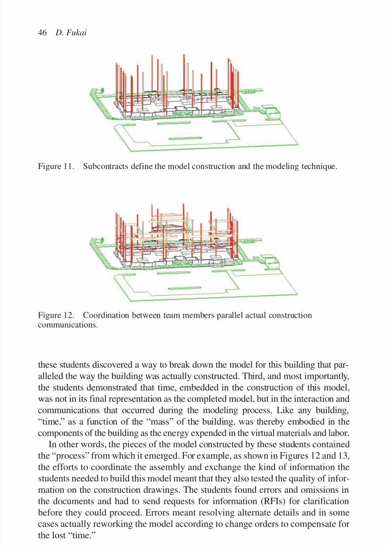
7/14/2019 4DCAD and Visualization in Construction
http://slidepdf.com/reader/full/4dcad-and-visualization-in-construction-56327c6a084e9 55/296
these students discovered a way to break down the model for this building that par-
alleled the way the building was actually constructed. Third, and most importantly,the students demonstrated that time, embedded in the construction of this model,was not in its final representation as the completed model, but in the interaction andcommunications that occurred during the modeling process. Like any building,“time,” as a function of the “mass” of the building, was thereby embodied in thecomponents of the building as the energy expended in the virtual materials and labor.
In other words, the pieces of the model constructed by these students containedthe “process” from which it emerged. For example, as shown in Figures 12 and 13,
the efforts to coordinate the assembly and exchange the kind of information thestudents needed to build this model meant that they also tested the quality of infor-mation on the construction drawings. The students found errors and omissions inthe documents and had to send requests for information (RFIs) for clarificationbefore they could proceed. Errors meant resolving alternate details and in somecases actually reworking the model according to change orders to compensate forthe lost “time.”
46 D. Fukai
Figure 11. Subcontracts define the model construction and the modeling technique.
Figure 12. Coordination between team members parallel actual constructioncommunications.

7/14/2019 4DCAD and Visualization in Construction
http://slidepdf.com/reader/full/4dcad-and-visualization-in-construction-56327c6a084e9 56/296
THE FOURTH DIMENSION AS A COMMUNICATIONS PROCESS
Most importantly, students had to communicate with each other to verify andcoordinate their work. This goes beyond the idea of collaboration and visualiza-tion and more toward the directed and purposeful interaction that occur during theactual construction process. The two-dimensional drawings for the building weretherefore critical to complete the virtual construction. This means there was no
intent to achieve a predictable result, no neat representation of phasing, or pre-conception of assemblies intended to visually represent three-dimensional space.The modeling effort became a precursor to the actual construction process and theinformation that resulted was useful as a pattern of communications indexed bythe individual pieces of the model.
For example, in the virtual construction of this building, contact points and inter-faces between the components of “subcontracts” had to be continually checked tomake sure they fit together as shown on the drawings. Any error would be com-pounded in much the same way as the physical construction. This meant studentshad to calculate dimensions and the coordinates of assembly points to make sureprefabricated pieces would fit when they were “delivered” to the virtual job site. Insome cases, this meant waiting until the assembly was complete before beginningprefabrication by transferring the project file to a “subcontractor” in much the sameway the same subcontractors might move onto the job site to custom fit their por-tion of the work. Model construction therefore meant conflicts were discovered in
4D CAD in construction communications 47
Figure 13. The pre-construction model allows analysis of lifts to erect trusses.
7/14/2019 4DCAD and Visualization in Construction
http://slidepdf.com/reader/full/4dcad-and-visualization-in-construction-56327c6a084e9 57/296
much the same way they might be found in the field. In fact, many of the changesmade to the model were visible in the completed building.
These changes and the conflicts that were discovered in the pre-construction of
this building were valuable as a precursor of the actual construction process, butthe pattern of communications about the construction of this model emerged as thelesson learned from this experiment. The communications log showed that timeand space were in fact changed by the construction. In the analogy of Einstein’stheory: time, or the warp of time, occurred as the “mass” of the constructionmodel disturbed or changed the vector of assumptions made from a particularpoint of view. In other words, as one might suspect, a series of errors, omissions,and requests for information indicated the need for change orders that adjustedboth scope and schedule.
Though a simple experiment, and certainly not intended to be the kind of proof that Einstein sought for his hypothesis, it seems like this idea might in fact pointin a different direction for what is more commonly thought to be 4D CAD. It alsosuggests a more a robust use of computer modeling, giving a “hands-on” experi-ence from which to learn about constructing buildings while simultaneously pre-viewing the quality of the construction documents. What is important is that theresultant model was 4D CAD, but unlike a sequential visual explanation like theseries of images shown in Figure 14, time became the distortions and changes that
were visible in the pre-construction communications.First, the modeling effort turned up errors and omissions in the construction
drawings. This would be important to limiting requests for information, clarifica-tions, and change orders that would have occurred during the actual construction.Second, the model helped to understand the quantities and methodologies associ-ated with the materials and labor that would be part of the same process. In prac-tice, this would help verify estimates and strengthen confidence in work plansimply because the construction process could be evaluated from the construction
model rather than traditional two-dimensional drawings and specifications. Third,the resultant model provided an archive of graphical images indexed according tothe pieces of the construction that would support future construction communica-tions. This includes zoomed close-ups, three-dimensional details, time sequence orphased images, and two-dimensional projections used as shop drawings or fieldclarifications in both the building and the falsework, formwork, and special struc-tures for the project.
The pedagogical opportunities are equally exciting. One of the conclusions of
the students involved in the experiment was that the experience had taught them alot about constructing a building. They pointed out that they were also able to con-textualize many of the things they had learned in other construction classes. Forexample, as shown in Figure 15, the construction of the running bond and rein-forcing on a CMU wall is quickly modeled in a class assignment.
If this is true, a similar 4D CAD experience for a specially designed buildingmight be useful as a tool in construction education. The overall learning strategy
48 D. Fukai

7/14/2019 4DCAD and Visualization in Construction
http://slidepdf.com/reader/full/4dcad-and-visualization-in-construction-56327c6a084e9 58/296
4D CAD in construction communications 49
Figure 15. Modeling a CMU wall teaches a lot about the actual construction of that wall.
Figure 14. Actual construction is enhanced by communications during the pre-constructionmodeling process.

7/14/2019 4DCAD and Visualization in Construction
http://slidepdf.com/reader/full/4dcad-and-visualization-in-construction-56327c6a084e9 59/296
of such a tool might include a construction project that allowed students to work in teams to complete the assembly of a virtual project. Students would then break
the work down and interact with each other to build the virtual model withinthe time constraints. In these interactions, students would have to read the two-dimensional plans, use hand-drawings to communicate their ideas in face-to-facemeetings, build portions of the building, and transfer their ideas to other teammembers as email attachments. This could be supplemented by a full size versionof the construction model to give students a hands-on feel for the actual construc-tion (see Fig. 16).
After completing the virtual construction they strengthened their plan-reading
skills and their ability to visualize a three-dimensional object from two-dimensionalplans. This suggests they could use hand-drawings and computer images to spon-taneously visualize the construction. And perhaps most importantly they would beable to review the entire process to understand the context of their actions and howa similar pre-construction effort might be used for other projects.
PRE-CONSTRUCTION AS PRE-COMMUNICATIONS
In an informal market study, the notion that buildings can be “pre-constructed” ona computer from a set of construction documents using the same labor and mate-rials that would be used on an actual job site seemed to stir the interest of con-struction managers (Fukai, 1996a). In its simplest form this means prethinking abuilding prior to its construction; but it also means using computer modeling to
50 D. Fukai
Figure 16. Construction model and physical construction can be used in combinationto test ideas and planning.
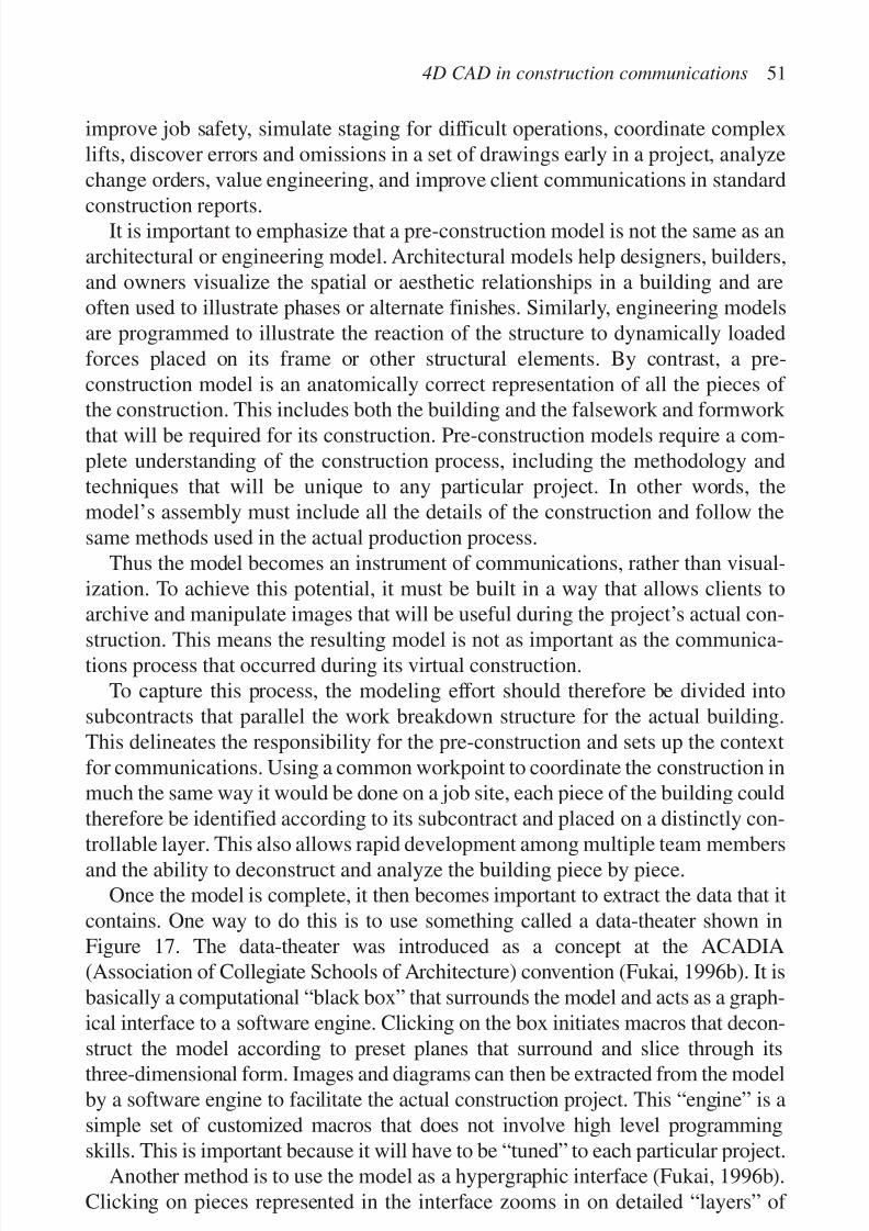
7/14/2019 4DCAD and Visualization in Construction
http://slidepdf.com/reader/full/4dcad-and-visualization-in-construction-56327c6a084e9 60/296
improve job safety, simulate staging for difficult operations, coordinate complexlifts, discover errors and omissions in a set of drawings early in a project, analyzechange orders, value engineering, and improve client communications in standard
construction reports.It is important to emphasize that a pre-construction model is not the same as anarchitectural or engineering model. Architectural models help designers, builders,and owners visualize the spatial or aesthetic relationships in a building and areoften used to illustrate phases or alternate finishes. Similarly, engineering modelsare programmed to illustrate the reaction of the structure to dynamically loadedforces placed on its frame or other structural elements. By contrast, a pre-construction model is an anatomically correct representation of all the pieces of the construction. This includes both the building and the falsework and formwork that will be required for its construction. Pre-construction models require a com-plete understanding of the construction process, including the methodology andtechniques that will be unique to any particular project. In other words, themodel’s assembly must include all the details of the construction and follow thesame methods used in the actual production process.
Thus the model becomes an instrument of communications, rather than visual-ization. To achieve this potential, it must be built in a way that allows clients toarchive and manipulate images that will be useful during the project’s actual con-
struction. This means the resulting model is not as important as the communica-tions process that occurred during its virtual construction.
To capture this process, the modeling effort should therefore be divided intosubcontracts that parallel the work breakdown structure for the actual building.This delineates the responsibility for the pre-construction and sets up the contextfor communications. Using a common workpoint to coordinate the construction inmuch the same way it would be done on a job site, each piece of the building couldtherefore be identified according to its subcontract and placed on a distinctly con-
trollable layer. This also allows rapid development among multiple team membersand the ability to deconstruct and analyze the building piece by piece.
Once the model is complete, it then becomes important to extract the data that itcontains. One way to do this is to use something called a data-theater shown inFigure 17. The data-theater was introduced as a concept at the ACADIA(Association of Collegiate Schools of Architecture) convention (Fukai, 1996b). It isbasically a computational “black box” that surrounds the model and acts as a graph-ical interface to a software engine. Clicking on the box initiates macros that decon-
struct the model according to preset planes that surround and slice through itsthree-dimensional form. Images and diagrams can then be extracted from the modelby a software engine to facilitate the actual construction project. This “engine” is asimple set of customized macros that does not involve high level programmingskills. This is important because it will have to be “tuned” to each particular project.
Another method is to use the model as a hypergraphic interface (Fukai, 1996b).Clicking on pieces represented in the interface zooms in on detailed “layers” of
4D CAD in construction communications 51

7/14/2019 4DCAD and Visualization in Construction
http://slidepdf.com/reader/full/4dcad-and-visualization-in-construction-56327c6a084e9 61/296
supporting visual information. For example, excavation, backfill, concrete, and
reinforcing steel can again be represented in the model as subcontracts on differentlayers so that they can be displayed separately or in different combinations. Theorganization of these layers and the way they are “called” by the graphical linkswould allow users to dynamically deconstruct the model by moving toward evermore detailed representations of the construction.
Both of these methods point to a graphical interface that leads to an infinitecollection of dynamically generated “snapshots” of the pre-construction model.
52 D. Fukai
Figure 17. A data-theater surrounds the model to annotate layout planes.
Figure 18. Two-dimensional construction drawings can be generated from thefour-dimensional modeling process.

7/14/2019 4DCAD and Visualization in Construction
http://slidepdf.com/reader/full/4dcad-and-visualization-in-construction-56327c6a084e9 62/296
This means that there is no part of the building, before or after its construction,that will not have a graphical representation available for inclusion in daily ormonthly reports, presentations to clients or subcontractors, websites, service man-
uals, and ongoing management and repair of the facility. In addition, many partsof the building will have detailed annotated two and three-dimensional layoutsthat can be used to direct the construction. These layouts are generated from thethree-dimensional drawings (see Fig. 18).
CONCLUSION
The challenge is to explore the modeling process in the context of an actual con-struction project in order to search for the revolutionary insight that must be partof what is truly the fourth dimension. Missing from a three-dimensional model isthe communications that is embedded in the construction simulation.
The perceptive shift is not in our view of the model, but in a sideways view atthe communications associated with that model’s construction within its virtualenvironment. Extracting the graphical data associated with the flow of that com-munication provides the constructor with an archive of visual explanations that
could thereby anticipate the interactions that will occur in the actual constructionprocess. In this way, pre-construction becomes pre-communications, and the effortsuggests a new graphical “intelligence” that might be added to support an industryof complex practices.
In conclusion, if there is to be a radical shift in our world view as we move fromthree to four dimensions, perhaps it must occur in the kind of communicationsrepresented by the pre-construction modeling process rather than the model itself.
REFERENCES
Aalami, F. & Fischer, M. 1998. Construction method models: the glue between design andconstruction. Proceedings of the 1998 international computing congress on computingin civil engineering: 376–378. Boston: ASCE.
Abbott, E.A. 1952. Flatland, 6th edition. Dover Publications.Cardone, F., Francaviglia, M.& Mignani, R. 1999. Five dimensional relativity with energy
as the extra dimension. General Relativity and Gravitation 31(7): 1049.
Falcioni, J.G. 1999. Managing product life cycles. Mechanical Engineering, CIME, 121:4 (editorial).Fukai, D. 1996a. A WORLD of data: an animated hypergraphic construction information
system. Presentation to the Association for Computer Aided Design in Architecture,Tucson, AZ, October 1996 .
Fukai, D. 1996b. Real-world, real-time, real-fast: using a trainer in a computer mediatedclassroom. A presentation as a fellow to the Materials and Technology Institute of the Association of Collegiate Schools of Architecture, Berkeley, CA, 1996 .
4D CAD in construction communications 53

7/14/2019 4DCAD and Visualization in Construction
http://slidepdf.com/reader/full/4dcad-and-visualization-in-construction-56327c6a084e9 63/296
Fukai, D. (unpublished paper). Current Research: Insitebuilders.com. M.E. Rinker Schoolof Building Construction, College of Architecture, University of Florida.
Hofstadter, D.R. 1980. Godel, Escher, Bach: An Eternal Golden Braid. Vintage Books.Jerrens, K.K. 1999. NIST’s support of rapid prototyping standards. IEEE Spectrum 36(2): 38
Johnson, D. 1999. Discuss and change models in real time. Design News May 3, 1999:96–101.
Kamarani, A.K. 1999. Direct engineering: toward intelligent manufacturing. KlumerAcademic, Monograph.
LaCourse, D. 1990. How solid modeling previews the future. Design News 46(10):May 10, 1990: 90–92.
McKinney, K., Kim, J., Fischer, M. & Howard, C. 1999. Interactive 4D-CAD. Computingin Civil Engineering: 383–389.
Potter, C.D. 1998. Process control CAD/CAM’s newest tool aims to oversee both thedata and the methods used to design complex assemblies. Computer Graphics World 22(8): 69.
Shah, J.J. & Wilson, P.R. 1988. Analysis of knowledge abstraction, representation andinteraction requirements for computer aided engineering. Computers in Engineering,1988 – Proceedings.
Vaugn, F. 1996. three-dimensional and 4D CAD modeling on commercial design-buildprojects. Computer in Civil Engineering 1996: 390–396.
Wei, D. & Gibson, K. 1998. Computer visualization: an integrated approach for interior design and architecture. McGraw-Hill.
Wilson, J. 1997. AutoCAD: a visual approach. Autodisk Press.
Wright, V.E. 1994. 4D CAD. Heating, Piping, Air Conditioning 56 (July 1984): 41–53.Yamaguchi, T. & Liu, H. 1998. Computational visualization of external and internalbiological flows with fluid-wall interactions. Advances in Bioengineering 39: 127–128.American Society of Mechanical Engineers: Bioengineering Division.
54 D. Fukai
7/14/2019 4DCAD and Visualization in Construction
http://slidepdf.com/reader/full/4dcad-and-visualization-in-construction-56327c6a084e9 64/296
FULLY INTEGRATED AND AUTOMATED PROJECTPROCESS (FIAPP) FOR THE PROJECT MANAGER ANDEXECUTIVE
F.H. (Bud) Griffis, Carrie S. Sturts
Department of Civil Engineering and Engineering Mech,
Columbia University, NY, USA
55
Abstract
Fully integrated and automated project process (FIAPP) is an acronym suggested by the
research committee of the Construction Industry Institute. A schedule linked to a three-
dimensional model (or 4D CAD) is a component of a larger FIAPP picture. This paper
briefly describes 4D CAD in the context of the larger picture of FIAPP and the three-dimensional computer model. The focus of our research has been on the use of three-
dimensional computer models for construction management. Furthermore, we focus on the
industrial process or commercial power projects because they are routinely designed in
three dimensions. This paper introduces some of the benefits of using three-dimensional
models for construction and the conclusions developed in a three-year research project into
FIAPP and 3D CAD that relate to 4D CAD development and usage. This discussion is illus-
trated with a case study project: the construction of an Air Separation Plant in Baytown,
Texas. Finally, this paper discusses a possible course outline to teach project managers and
project executives how to benefit from using FIAPP in the management of the constructionproject process. Unless project personnel actually have hands on use of the model, it loses
its value as design is turned over to construction. Therefore the state of the art can only be
advanced if project personnel feel comfortable operating in a FIAPP environment.
Keywords: FIAPP, training, advantages, 3D CAD
BACKGROUND
The process and power industries routinely use 3D CAD in design and construction;however, most building and heavy construction projects are still being designedand constructed using two dimensions. Given that contractors work from two-dimensional drawings, unless the designers are proficient in three-dimensionaldesign, there are probably few benefits to be gained from three dimensions for
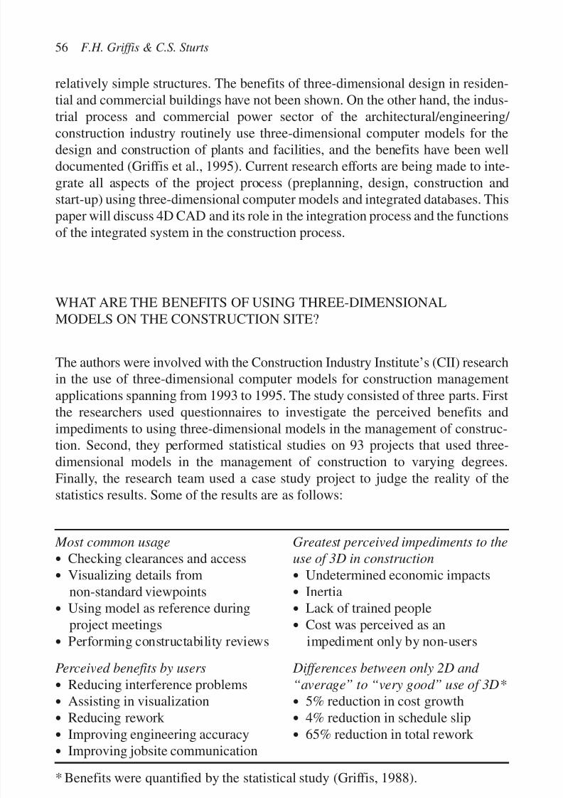
7/14/2019 4DCAD and Visualization in Construction
http://slidepdf.com/reader/full/4dcad-and-visualization-in-construction-56327c6a084e9 65/296
relatively simple structures. The benefits of three-dimensional design in residen-tial and commercial buildings have not been shown. On the other hand, the indus-trial process and commercial power sector of the architectural/engineering/
construction industry routinely use three-dimensional computer models for thedesign and construction of plants and facilities, and the benefits have been welldocumented (Griffis et al., 1995). Current research efforts are being made to inte-grate all aspects of the project process (preplanning, design, construction andstart-up) using three-dimensional computer models and integrated databases. Thispaper will discuss 4D CAD and its role in the integration process and the functionsof the integrated system in the construction process.
WHAT ARE THE BENEFITS OF USING THREE-DIMENSIONALMODELS ON THE CONSTRUCTION SITE?
The authors were involved with the Construction Industry Institute’s (CII) researchin the use of three-dimensional computer models for construction managementapplications spanning from 1993 to 1995. The study consisted of three parts. First
the researchers used questionnaires to investigate the perceived benefits andimpediments to using three-dimensional models in the management of construc-tion. Second, they performed statistical studies on 93 projects that used three-dimensional models in the management of construction to varying degrees.Finally, the research team used a case study project to judge the reality of thestatistics results. Some of the results are as follows:
Most common usage Greatest perceived impediments to the
• Checking clearances and access use of 3D in construction
• Visualizing details from • Undetermined economic impactsnon-standard viewpoints • Inertia
• Using model as reference during • Lack of trained peopleproject meetings • Cost was perceived as an
• Performing constructability reviews impediment only by non-users
Perceived benefits by users Differences between only 2D and
• Reducing interference problems “average” to “very good” use of 3D*• Assisting in visualization • 5% reduction in cost growth
• Reducing rework • 4% reduction in schedule slip
• Improving engineering accuracy • 65% reduction in total rework
• Improving jobsite communication
* Benefits were quantified by the statistical study (Griffis, 1988).
56 F.H. Griffis & C.S. Sturts

7/14/2019 4DCAD and Visualization in Construction
http://slidepdf.com/reader/full/4dcad-and-visualization-in-construction-56327c6a084e9 66/296
These benefits are impediments that may specifically apply to 4D CAD in vary-ing magnitude; however further research should be conducted to isolate the bene-fits of 4D CAD for various project types and at different management levels. The
case study project was used to actually perform cost estimates of the benefits asthey occurred in the field. Those direct cost benefits exceeded those predicted bythe statistical computer models. (Griffis et al., 1995).
WHAT IS FIAPP?
We have come to the conclusion that the greatest benefits from the three-dimensional computer model come from the integrated databases and not just
from the three-dimensional computer model. Four-dimensional computer modelsare part of a larger picture. Researchers at CII have coined the term fully inte-grated and automated project process (FIAPP) to describe this bigger picture.FIAPP is not a software system per se, but an idea about the future computer datasystems that will support a project from inception to start-up and beyond. FIAPPdescribes how information will flow automatically from one system to another,from one project participant to another, from owner to designer to fabricator to
constructor. FIAPP and the relationship of the three-dimensional model to theother systems is still being debated.
When we use the term FIAPP, we include all activities in the pre-project plan-ning, the design, the procurement, the construction management, the start-up, andthe operations and maintenance phases.
In the ideal FIAPP (Fig. 1), all systems are integrated from payroll to job cost-ing to scheduling to the design systems. Of most interest to construction managers
Fully integrated and automated project process 57
FIAPP
ProjectMgt
Systems
ProcurementSystems
F&A
Systems
Design &AnalysisSystems
HRSystems
MaterialsMgt
Systems
3DComputer
Model
Figure 1. The fully integrated and automated project process.

7/14/2019 4DCAD and Visualization in Construction
http://slidepdf.com/reader/full/4dcad-and-visualization-in-construction-56327c6a084e9 67/296
is a subsystem of FIAPP consisting of the three-dimensional model, the PM systems,the procurement systems and the material management systems. It is within thesesystems that we will consider 4D CAD. The three-dimensional computer model
(Fig. 2) progresses from the design phase with output to the project managementsystems, construction field operations and the procurement and material manage-ment systems. These systems in turn provide feedback to the model and/or itsassociated databases.
Many feel that the three-dimensional computer model is but one of the data-bases associated with FIAPP. Others feel it is the hub of the system through whichthe other databases are accessed. Figure 3 illustrates these two different integra-tion schemes.
For many projects, much of the design and procurement is initiated long beforea detailed three-dimensional computer model is available. The design often startswith the process flow diagrams (PFDs) and the piping and instrumentation dia-grams (P&IDs). The front end engineering design (FEED) generally consistsof PFDs, preliminary P&IDs, multiple simulation cases and cost comparisons,detailed equipment data sheets, request for quotation responses, general equip-ment and piping layouts and early three-dimensional computer model reviews
58 F.H. Griffis & C.S. Sturts
GEOMETRICDATABASE
OTHERDATABASES
GRAPHICS3D
DATABASE
ENGINEERING
DESIGN
AND
ANALYSIS
Procurementand
Material
Management
ProjectManagement
ConstructionField
Operations
Figure 2. The three-dimensional computer model and its relationships with thedesign and construction process.

7/14/2019 4DCAD and Visualization in Construction
http://slidepdf.com/reader/full/4dcad-and-visualization-in-construction-56327c6a084e9 68/296
(Carell, 1999). Most of the piping, piping accessories, and major equipment itemsare developed in this stage and some of the procurement may be initiated (Fig. 4).This initial development supports the wheel model for FIAPP; however, there arethose who feel that once an initial model is developed, it should be the center andorganization format for the project data. FIAPP is still in development.
4D CAD AND FIAPP
The following rendering is of the case study project (Fig. 5) upon which this paperis based. 4D CAD was not used in this case study project although it was tried.
Fully integrated and automated project process 59
DB 2
DB 1
DB 3
DB n
3D ModelDB 3
DB 2
DB 1 DB n3D
Model ?
Figure 3. Spoke concept versus the wheel concept of FIAPP.
Figure 4. Piping planning.

7/14/2019 4DCAD and Visualization in Construction
http://slidepdf.com/reader/full/4dcad-and-visualization-in-construction-56327c6a084e9 69/296
There were numerous reasons that it was not used. This project was the projectteam’s first attempt to use three-dimensional computer models in the managementof construction. The way in which the three-dimensional model was developedgreatly inhibited the attempt to use 4D CAD. We found that 4D CAD was impos-sible to use with this model. The system was designed in Intergraph PDS and thirdparty add-ins. The organization of the model was done so as to preclude separat-ing the commodities and groupings into activities. First, the underground civilwork was not modeled. (We have found this to be a shortcoming in most models
and will recommend that civil work be modeled in the future.) The civil work could not be scheduled, however, from the model. Secondly, there is the issue of the plant design area relationship to the construction area. Plant design areas takeform during front-end project planning. The areas are developed using associatedequipment usually by the process section or by the process system. If areas aresystem based, they can overlap. Construction areas should use the same geo-graphical boundaries as the plant design areas. Construction zones are used toidentify physically defined subsets of design areas and are identified by design
element attributes. Specific design element attributes can be used to identify thespecific subcontractor work packages. Work packages are usually based on geo-graphical boundaries and specify subcontractor data and system tie-in packages.Work is usually controlled by line list data and subcontract data by specific spoolnumber. A back-to-front schedule establishes the design release by constructionarea or sub-area and is issued as a design area package (Hall, 1999). Finally,
60 F.H. Griffis & C.S. Sturts
Figure 5. Baytown case study project.

7/14/2019 4DCAD and Visualization in Construction
http://slidepdf.com/reader/full/4dcad-and-visualization-in-construction-56327c6a084e9 70/296
the project team did not feel that the value of using 4D CAD on the project sitewould justify the effort of trying to make the model compatible with the 4D CADsoftware.
The contractors required two-dimensional paper drawings. The work packageswere put together from these drawings and scheduled by experienced engineers.The benefits of the 4D CAD could not be imagined. Based on this fact, we tried toanticipate what the benefits of using 4D CAD on a project this size could be if themodel was developed in such a method as to facilitate its use. The followingpotential benefits were noted:
• If the model were developed early enough, a 4D CAD approach would havebeen of benefit to permit the Board of Directors to make financial decisionsregarding the plant.
• A 4D CAD approach could have been valuable tool for the marketing depart-ment in their effort to sell the product.
• A 4D CAD analysis could have helped with the interface with the Exxon plantto which liquid oxygen was to be piped.
• A 4D CAD modeling approach might have found some scheduling errors in theconstruction of the plant. However, there were no important scheduling delaysencountered. Numerous conflicts were found and resolved in the field.
COURSE OUTLINE: USING FIAPP FOR PROJECT MANAGERSAND EXECUTIVES
This course will acquaint the project manager or project executive with the use of
three-dimensional computer models to enable an understanding of the evolutionof the fully integrated and automated project process. The course will involvecomputer software. However, it will not be a programming course. It will requireunderstanding of the software characteristics and the manipulation of the software.In this course, we will use mostly software marketed by Bentley Systems. Thissoftware is not the only available software that will do the job that we require andit may not be the absolute best software for what we are after. Nevertheless, it is easyto learn and robust enough to serve our purposes. The course is a one-semestercourse consisting of 45 contact hours. It uses a relatively simple (but not trivial)
construction project as a semester project.
Objectives of the course
• To acquaint the project management professional or the project executive withthe concept of FIAPP.
Fully integrated and automated project process 61

7/14/2019 4DCAD and Visualization in Construction
http://slidepdf.com/reader/full/4dcad-and-visualization-in-construction-56327c6a084e9 71/296
• To acquaint the project management professional or the project executive withthe software in use, and to train him or her to have the facility to use the soft-ware in the management of construction.
Session #1: Introduction
• Discussion of the background of FIAPP.
• Examples of some three-dimensional computer models.
Session #2: Pre-project planning using 3D-FIAPP
If a company is building a first of its kind facility, there will be no detailed three-dimensional model in place during the pre-project planning phase. However, thestate of the art is such that a conceptual model, populated by geometric objects,can be readily developed in the pre-project planning phase. This model can resultin considerable payoff. As the model is developed, associated databases are popu-lated. As business objectives are defined and market research and analyses aremade, the preliminary model is populated with graphic and geometric data andexternal databases are defined and linked to the model.
As the facility objectives and capacity demands are computed however, themodel is developed further. Concepts of operation of the facility are adjusted bywhat-if trials with the model. The model helps address regulatory issues such as
initial permitting, wetlands issues, and waste disposal issues. Depending on theproject, the initial block model greatly enhances the public relations presentationsand presentations to the funding approval body of the organization. While the processand facility planning is initially accomplished by line diagrams, the initial prelim-inary model quickly becomes a facilitator for equipment and vessel placement,transmission line routing, customer interaction, and transportation arrangement.
As project execution begins, the preliminary model is used to develop the con-tracting strategy. As major items of equipment are modeled, fabrication contracts are
drafted. Using the plan view of the model, the project geography is developed andcontract procurement strategies are initiated. The project scope is set, initial discus-sions begin with potential contractor bidders and bid package scope developmentbegins. The EPC contractor team uses the model to assure that each organizationunderstands its scope and its interface with each of the other organizations. Themodel serves as a vehicle for discussions with environmental agencies, negotiationswith offsite utility providers, and future operations and maintenance personnel. Theowner and designers begin product development, and accumulate certification and
testing procedures databases which they attach to the objects in the model.The state of the art with respect to hardware and software makes the developmentof a primitive block model exceptionally easy. Ideally, one starts with the samecoordinate system as will be used in the design and construction of the project. Allof the popular CAD software perform in true three-dimension space today. Theinitial project model is a relatively small model. The hardware systems can read-ily facilitate the model manipulation in real time. Projection systems that can handle
62 F.H. Griffis & C.S. Sturts

7/14/2019 4DCAD and Visualization in Construction
http://slidepdf.com/reader/full/4dcad-and-visualization-in-construction-56327c6a084e9 72/296
1280 ϫ 1024 are currently on the market and available for project meetings andpresentation and the technology will improve.
INTRODUCTION TO MICROSTATION: DEVELOP SMALL BLOCKMODEL IN MICROSTATION
Session #3: Pre-project planning (continued)
Introduction to PlantSpace Enterprise Navigator. Convert small block model fromdgn file to jsm file. Use PlantSpace Enterprise Navigator to view the block model.Study features of navigator.
Session #4: Introduction to databases
Introduction to Microsoft Access. We propose to use Microsoft Access as the data-base driver since it is so readily available. There are other, more powerful programssuch as Oracle that could also be used. In this session the concept of procurementdatabases is proposed. By the end of the preplanning phase of a project, the fol-lowing databases will probably be initiated and population of data items begun:
• major equipment lists,• raw material vendors and other sources for product,
• bulk material vendors for construction product procurement,
• regulatory permit register,
• process preliminary design criteria,
• P&ID preliminaries,
• major equipment criteria,
• start-up procedure design criteria,
• labor with cost and productivity,
• quantities,
• cost estimate,
• schedule,
• work breakdown structure.
To begin learning Microsoft Access, a sample procurement table will be devel-oped. The concept of object based programming is introduced. The access data-base will be linked to the Microstation by its Open DataBase Connectivity
(ODBC) linking capabilities.
Session #5: Introduction to project design using Microstation
The object of this session is not to turn the student into a designer but to refresh themanager’s concept about how design in a three-dimensional world is accomplished.This is important because the naming conventions, the file designs, and other designorganizational matters will affect the use of the tools on the construction project.
Fully integrated and automated project process 63
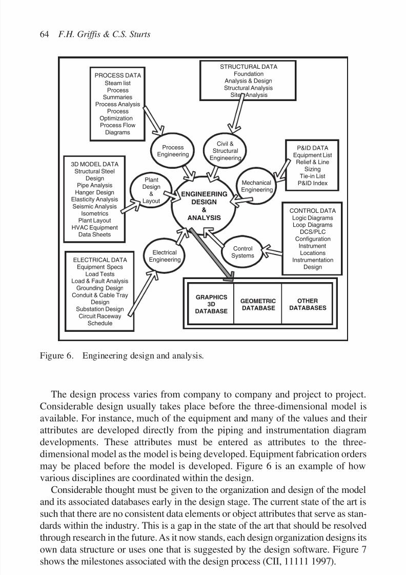
7/14/2019 4DCAD and Visualization in Construction
http://slidepdf.com/reader/full/4dcad-and-visualization-in-construction-56327c6a084e9 73/296
The design process varies from company to company and project to project.Considerable design usually takes place before the three-dimensional model isavailable. For instance, much of the equipment and many of the values and theirattributes are developed directly from the piping and instrumentation diagramdevelopments. These attributes must be entered as attributes to the three-dimensional model as the model is being developed. Equipment fabrication ordersmay be placed before the model is developed. Figure 6 is an example of howvarious disciplines are coordinated within the design.
Considerable thought must be given to the organization and design of the modeland its associated databases early in the design stage. The current state of the art issuch that there are no consistent data elements or object attributes that serve as stan-dards within the industry. This is a gap in the state of the art that should be resolvedthrough research in the future. As it now stands, each design organization designs itsown data structure or uses one that is suggested by the design software. Figure 7shows the milestones associated with the design process (CII, 11111 1997).
64 F.H. Griffis & C.S. Sturts
PlantDesign
&Layout
3D MODEL DATAStructural Steel
DesignPipe Analysis
Hanger Design
Elasticity AnalysisSeismic Analysis
IsometricsPlant Layout
HVAC EquipmentData Sheets
ENGINEERING
DESIGN&
ANALYSIS
ProcessEngineering
PROCESS DATA
Steam listProcess
SummariesProcess Analysis
ProcessOptimizationProcess Flow
Diagrams
Civil &Structural
Engineering
MechanicalEngineering
P&ID DATAEquipment ListRelief & Line
SizingTie-in List
P&ID Index
CONTROL DATALogic DiagramsLoop Diagrams
DCS/PLCConfiguration
InstrumentLocations
InstrumentationDesign
ElectricalEngineering
STRUCTURAL DATAFoundation
Analysis & DesignStructural Analysis
Site Analysis
ControlSystems
ELECTRICAL DATAEquipment Specs
Load TestsLoad & Fault Analysis
Grounding Design
Conduit & Cable TrayDesignSubstation DesignCircuit Raceway
Schedule
GEOMETRICDATABASE
OTHERDATABASES
GRAPHICS3D
DATABASE
Figure 6. Engineering design and analysis.
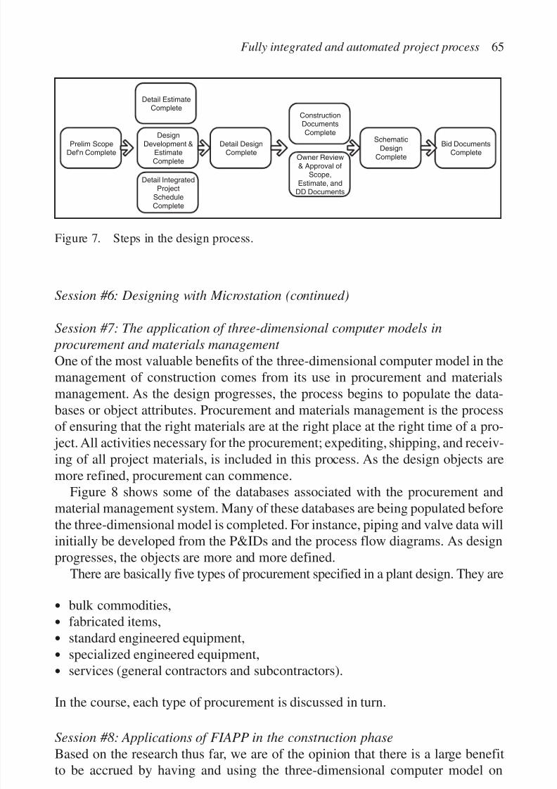
7/14/2019 4DCAD and Visualization in Construction
http://slidepdf.com/reader/full/4dcad-and-visualization-in-construction-56327c6a084e9 74/296
Session #6: Designing with Microstation (continued)
Session #7: The application of three-dimensional computer models in
procurement and materials management
One of the most valuable benefits of the three-dimensional computer model in themanagement of construction comes from its use in procurement and materialsmanagement. As the design progresses, the process begins to populate the data-
bases or object attributes. Procurement and materials management is the processof ensuring that the right materials are at the right place at the right time of a pro-
ject. All activities necessary for the procurement; expediting, shipping, and receiv-ing of all project materials, is included in this process. As the design objects aremore refined, procurement can commence.
Figure 8 shows some of the databases associated with the procurement andmaterial management system. Many of these databases are being populated beforethe three-dimensional model is completed. For instance, piping and valve data will
initially be developed from the P&IDs and the process flow diagrams. As designprogresses, the objects are more and more defined.
There are basically five types of procurement specified in a plant design. They are
• bulk commodities,
• fabricated items,
• standard engineered equipment,
• specialized engineered equipment,
•services (general contractors and subcontractors).
In the course, each type of procurement is discussed in turn.
Session #8: Applications of FIAPP in the construction phase
Based on the research thus far, we are of the opinion that there is a large benefitto be accrued by having and using the three-dimensional computer model on
Fully integrated and automated project process 65
Prelim ScopeDef'n Complete
Detail EstimateComplete
DesignDevelopment &
EstimateComplete
Detail IntegratedProject
ScheduleComplete
Detail DesignComplete
ConstructionDocuments
Complete
Owner Review& Approval of
Scope,Estimate, and
DD Documents
Schematic
DesignComplete
Bid DocumentsComplete
Figure 7. Steps in the design process.
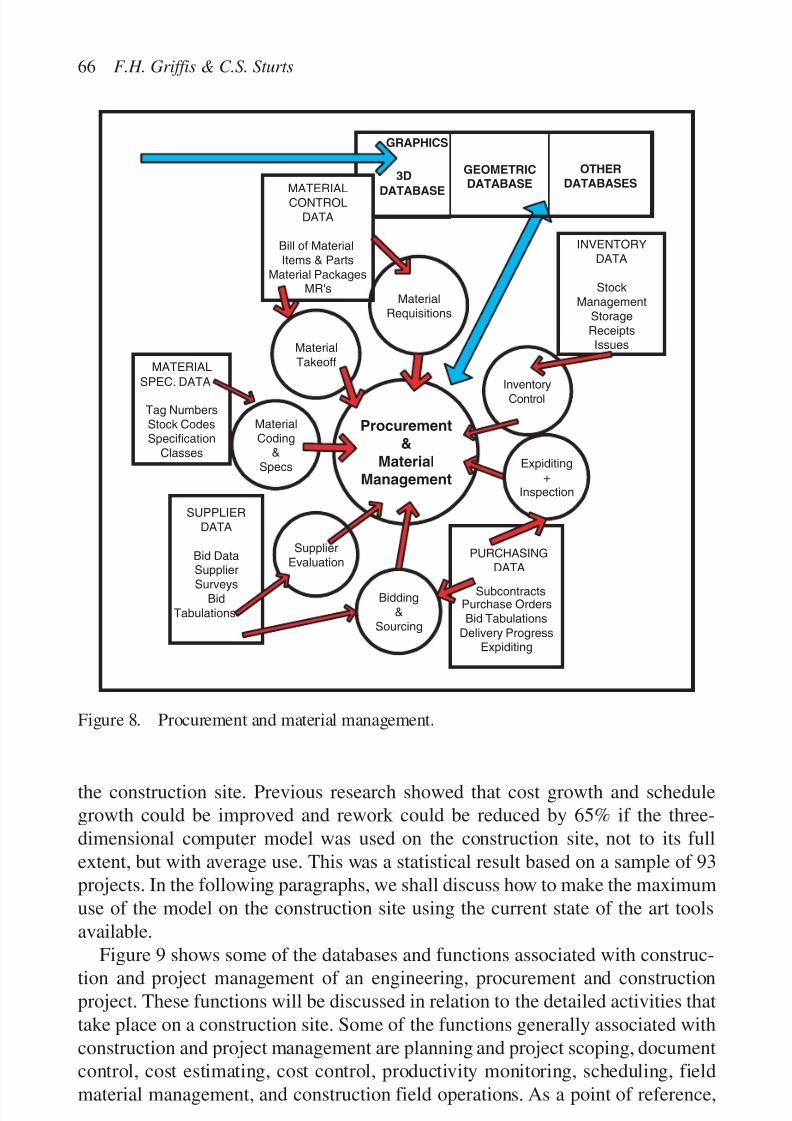
7/14/2019 4DCAD and Visualization in Construction
http://slidepdf.com/reader/full/4dcad-and-visualization-in-construction-56327c6a084e9 75/296
the construction site. Previous research showed that cost growth and schedulegrowth could be improved and rework could be reduced by 65% if the three-dimensional computer model was used on the construction site, not to its fullextent, but with average use. This was a statistical result based on a sample of 93projects. In the following paragraphs, we shall discuss how to make the maximumuse of the model on the construction site using the current state of the art toolsavailable.
Figure 9 shows some of the databases and functions associated with construc-tion and project management of an engineering, procurement and constructionproject. These functions will be discussed in relation to the detailed activities thattake place on a construction site. Some of the functions generally associated withconstruction and project management are planning and project scoping, documentcontrol, cost estimating, cost control, productivity monitoring, scheduling, fieldmaterial management, and construction field operations. As a point of reference,
66 F.H. Griffis & C.S. Sturts
GEOMETRICDATABASE
OTHER
DATABASES
GRAPHICS
3D
DATABASE
Material
Coding&
Specs
MATERIAL
SPEC. DATA
Tag Numbers
Stock CodesSpecification
Classes
Procurement
&
Material
Management
Material
Takeoff
MATERIALCONTROL
DATA
Bill of Material
Items & Parts
Material PackagesMR's
Material
Requisitions
InventoryControl
INVENTORY
DATA
Stock
Management
Storage
ReceiptsIssues
SUPPLIER
DATA
Bid DataSupplier
Surveys
Bid
Tabulations
Supplier
EvaluationPURCHASING
DATA
SubcontractsPurchase Orders
Bid Tabulations
Delivery ProgressExpiditing
Bidding
&
Sourcing
Expiditing+
Inspection
Figure 8. Procurement and material management.

7/14/2019 4DCAD and Visualization in Construction
http://slidepdf.com/reader/full/4dcad-and-visualization-in-construction-56327c6a084e9 76/296
Fully integrated and automated project process 67
we will use the case study project three-dimensional computer model as shown inFigure 10.
Consider the following functions in this session preparation:
• site mobilization (Fig. 11);• mobilize facilities;
• provide construction utilities;
• establish safety and quality;
• obtain permits and licenses;
• submit project documents (Fig. 12);
• establish security (Fig. 13);
Cost
Control
Document
ControlSystem
GEOMETRICDATABASE
OTHERDATABASES
GRAPHICS3D
DATABASE
Constructionand
ProjectManagement
SCHEDULING DATA
Preliminary Schedule
Detailed ScheduleEPC Interface Schedule
Construction Summary
Schedule
Engineering Summary
Schedule
Scheduling
PLANNING DATA
Project
Automation Plan
Quality Assurance
Plan
Contracting Plan
Project Execution
Plan
Design Scope
Book
Planning
and ProjectScoping
DOCUMENT
DATA
Document
Distribution
ControlLogInitiate & Review
Document
Performance
COST CONTROL DATA
Operating Plant Site Cost
Control Reports
Operating Plant Work Order
Control Reports
Cost & Commitment
Reports
ACWP and BCWP Reports
(by resource groups)
Engineering Performance
Reports
Accounts Payable
Payroll & Timekeeping
PERFORMANCE
&
PRODUCTIVITY
DATA
Contract
Progress
Committee
Reports
Labor
Performance
Cash Flow
Quantity and Unit
Rates
ProductivityMonitoring
ESTIMATING DATA
Order of MagnitudeEstimate
Preliminary Estimate
Definitive Estimate
CostEstimating
MATERIAL DATA
Material PackagingPurchasingExpediting
Inventory ConntrolRelease to Field
Material surplusing
Field
MatlMgt
INSTALLATIONDATA
VisualizationRigging
Installation ofPiping
Installation ofSteel
Installation ofEquipment
WeldingEquipment
Maintenance
Const
FieldOps
Figure 9. Construction and project management.

7/14/2019 4DCAD and Visualization in Construction
http://slidepdf.com/reader/full/4dcad-and-visualization-in-construction-56327c6a084e9 77/296
• develop materials management plan;
• develop execution strategy;
• define training procedures;
• plan for major action items;
• develop work plan (Fig. 14);
68 F.H. Griffis & C.S. Sturts
Figure 10. Preliminary model.
Figure 11. Baytown offices.
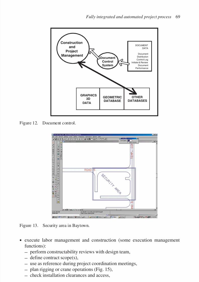
7/14/2019 4DCAD and Visualization in Construction
http://slidepdf.com/reader/full/4dcad-and-visualization-in-construction-56327c6a084e9 78/296
Fully integrated and automated project process 69
Figure 13. Security area in Baytown.
DocumentControlSystem
DOCUMENT
DATA
Document
Distribution
Control Log
Initiate & Review
Document
Performance
Construction
andProjectManagement
GEOMETRICDATABASE
OTHERDATABASES
GRAPHICS3D
DATA
Figure 12. Document control.
•execute labor management and construction (some execution managementfunctions):
– perform constructability reviews with design team,
– define contract scope(s),
– use as reference during project coordination meetings,
– plan rigging or crane operations (Fig. 15),
– check installation clearances and access,

7/14/2019 4DCAD and Visualization in Construction
http://slidepdf.com/reader/full/4dcad-and-visualization-in-construction-56327c6a084e9 79/296
– plan and sequence construction activities,
– plan survey control and construction layout,
– manage material layout yards or stockpiles,– exchange information with vendors,
– locate installation points in field,
– track construction progress,
– estimate costs,
– visualize project details or design changes,
– record “as-builts” conditions,
70 F.H. Griffis & C.S. Sturts
ESTIMATING DATA
Order of Magnitude
Estimate
Preliminary Estimate
Definitive Estimate
CostEstimating
SCHEDULING DATA
Preliminary ScheduleDetailed Schedule
EPC Interface ScheduleConstruction Summary
Schedule
Engineering SummarySchedule
Scheduling
Work Plan
Development
Figure 14. Work plan development.
Figure 15. Rigging operations.
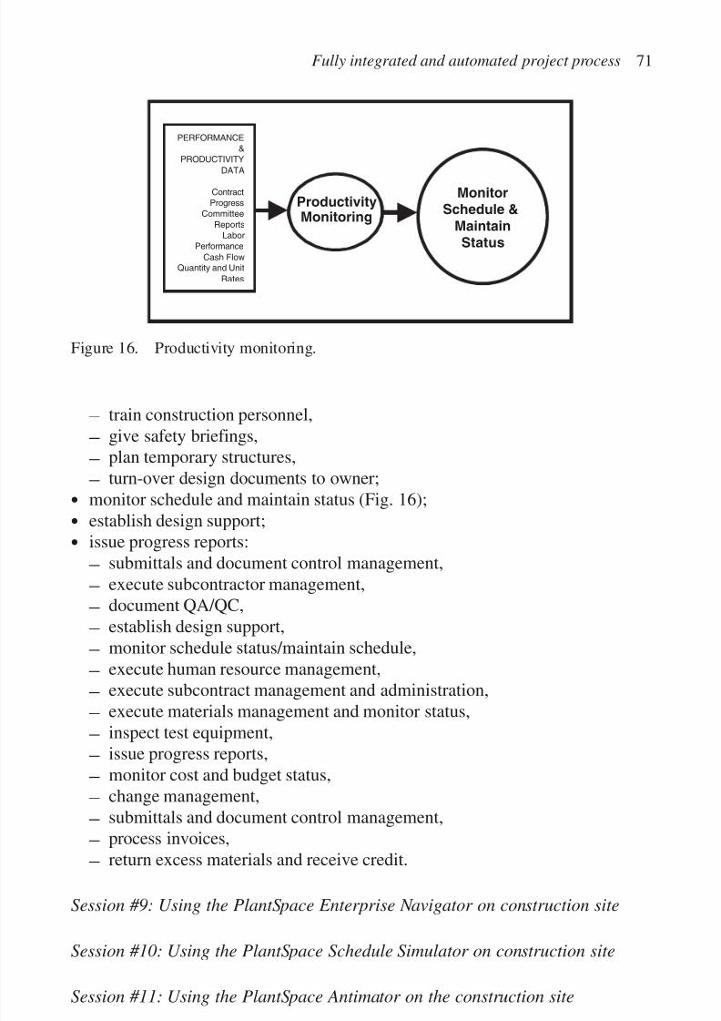
7/14/2019 4DCAD and Visualization in Construction
http://slidepdf.com/reader/full/4dcad-and-visualization-in-construction-56327c6a084e9 80/296
– train construction personnel,
– give safety briefings,
– plan temporary structures,
– turn-over design documents to owner;
• monitor schedule and maintain status (Fig. 16);
• establish design support;• issue progress reports:
– submittals and document control management,
– execute subcontractor management,
– document QA/QC,
– establish design support,
– monitor schedule status/maintain schedule,
– execute human resource management,
– execute subcontract management and administration,
– execute materials management and monitor status,
– inspect test equipment,
– issue progress reports,
– monitor cost and budget status,
– change management,
– submittals and document control management,
– process invoices,
– return excess materials and receive credit.
Session #9: Using the PlantSpace Enterprise Navigator on construction site
Session #10: Using the PlantSpace Schedule Simulator on construction site
Session #11: Using the PlantSpace Antimator on the construction site
Fully integrated and automated project process 71
PERFORMANCE
&
PRODUCTIVITY
DATA
Contract
Progress
Committee
Reports
Labor
Performance
Cash Flow
Quantity and Unit
Rates
ProductivityMonitoring
MonitorSchedule &
MaintainStatus
Figure 16. Productivity monitoring.

7/14/2019 4DCAD and Visualization in Construction
http://slidepdf.com/reader/full/4dcad-and-visualization-in-construction-56327c6a084e9 81/296
Session #12: Integrating the process
Session #13: Workshop to prepare individual projects
Session #14: Course presentations
Session #15: Course presentations
SUMMARY
This paper was begun with the emphasis of showing the results of over a decade of research in the applications of three-dimensional computer models and their asso-ciated databases to the management of construction. We have shown that there is anaverage of 5% savings in cost growth, 4% savings in schedule growth, and 65%savings in rework. Through the paper’s development, several facts became obvious.First, in order that the tools be useful throughout the process, the model and asso-ciated databases must be used. In investigating many companies, the proponent for
the tools were the information technology personnel and the design engineers thatwork with the systems all the time. Secondly, the management personnel generallyused their computers for word processing and analytics, but did little with highlevel graphics engines. Therefore, the second part of this paper is an outline of asingle semester course, consisting of 45 hours of classroom instruction with anobjective to acquaint management personnel with the applications of project inte-gration software. We found that with a little training, project personnel began tofeel comfortable using the three-dimensional computer model navigation software.The proposed course outline makes an effort to development a comfort level amongmanagement personnel for integration software. If project management personneluse the tools in the pre-project planning, design, procurement and materials man-agement, construction, start-up and commissioning phases of a project, unantici-pated savings will occur.
ACKNOWLEDGMENTS
The authors express appreciation to the National Science Foundation and theConstruction Industry Institute for supporting the research leading to this paper. Inaddition, we appreciate the support of the construction industry personnel servingon two CII Research Teams, 106 (Chairman John Voeller of Black and Veatch)and 152 (Chairman John Berra of H.B. Zachary Inc.) The thirty team members
72 F.H. Griffis & C.S. Sturts

7/14/2019 4DCAD and Visualization in Construction
http://slidepdf.com/reader/full/4dcad-and-visualization-in-construction-56327c6a084e9 82/296
provided a great deal of the research associated with project. Brent Senseny of AirProducts and Chemicals, Inc. provided liaison with the Baytown Plant case studyproject. Ron Zabilski, formerly of Stone and Webster Engineering Corporation
was a co-principal investigator on the NSF project that concluded in 1989.Doctors Dan Hogan and Winqing Li used the projects mentioned in this paper asa partial fulfillment of the requirements for a Doctor of Philosophy degree atColumbia University.
REFERENCES
Carell, R. 1999. Front end engineering design (FEED), CAD/CAE software strategies.Rebis Industrial Workgroup Software (unpublished paper).
CII. 1997. Determining the impact of process of change on the EPC process. ConstructionIndustry Institute Report IR125-2, July.
Griffis, F.H. 1988. Benefits of using three-dimensional computer models in the manage-ment of construction. National Science Foundation Report.
Griffis, F.H., Hogan, D. & Li, W. 1995. An analysis of the impacts of using three dimen-sional computer models in the management of construction. Construction IndustryInstitute. Research Report 106-11, September 1995.
Hall, 1999. Personal correspondence and discussions, Bechtel Corporation, Inc.
Fully integrated and automated project process 73

7/14/2019 4DCAD and Visualization in Construction
http://slidepdf.com/reader/full/4dcad-and-visualization-in-construction-56327c6a084e9 83/296

7/14/2019 4DCAD and Visualization in Construction
http://slidepdf.com/reader/full/4dcad-and-visualization-in-construction-56327c6a084e9 84/296
NEW CONSTRUCTION MANAGEMENT PRACTICE BASEDON THE VIRTUAL REALITY TECHNOLOGY
Jarkko Leinonen1, Kalle Kähkönen1, Tero Hemiö2, Arkady Retik 3,Andrew Layden4
1VTT Building and Transport, Finland 2 Eurostepsys Ltd., Finland 3School of the Built and Natural Environment, Glasgow Caledonian University,
Glasgow, UK 4 Department of Civil Engineering, Division of Construction Management,
University of Strathclyde, Glasgow, UK
75
Abstract
This paper focuses on experiences of implementing 4D applications (3D building geometric
data ϩ time) to meet the needs of construction companies. The authors have been develop-ing and experimenting with 4D applications based on virtual reality (VR) technology and
its integration with other state of the art software. The objective of the paper is to provide
understanding for balancing possibilities and challenges of this approach for construction
planning and management.
Several case studies with YIT Corporation, a Finnish construction company, have pro-
vided basis for many findings to be presented in the paper. This long-term co-operation has
covered product modeling, software architecture design, web technology and, more recently,
4D together with VR. First the present problems originating from the current construction
planning practice are discussed. This is followed by presenting the possibilities of construc-tion management practice with the aid of 4D—what is needed and what can be achieved.
The 4D approach has been demonstrated in the live building construction project, THK
office building. The case study covers cost-benefit analysis of applying 4D for construction
planning.
Keywords: 4D, virtual reality, construction management, information technology, construc-
tion company
INTRODUCTION
Building construction is about transforming the vision and views of a client intoa building where the client’s needs and objectives are met. This process comprises

7/14/2019 4DCAD and Visualization in Construction
http://slidepdf.com/reader/full/4dcad-and-visualization-in-construction-56327c6a084e9 85/296
many stages and phases, iterative activities, and can have large numbers of partic-ipants involved having massive information transfer and communication needs.Furthermore, the practical set up of the building construction processes can vary
greatly from one project to another. A major reason for this is the technical differ-ences between projects. Another main reason is the varying building constructionskills, experience and knowledge of participants. This experience, skills andknowledge can vary greatly between different organizations involved and requirespecial attention.
It seems that in practice too many building construction processes are far fromthe most suitable processes. This results in clear and easily identifiable high costs,low productivity growth and poor quality, which, unfortunately, are internationallycommon features in building construction. Recent results from several studies showthat deficient management and organization are main causes of these shortcomings(Koskela, 2000). Additionally, Koskela shows that the main sources for productiondefect costs are the design and engineering phases and the production management.Likewise, deficient production planning has proved to be one of the underlyingreasons for the problems in the production management (Josephson & Hammarlund,1996). Consequently, it often happens that the design phase in a building constructionproject is realized without sufficient constructability consideration. Also, it has beendiscovered that the methods for decision support are ad hoc and unsystematic. This
is a root cause for many problems and disappointments in building constructionprojects (Laitinen, 1998).
The common feature of the important findings presented above is that they all arerelated to building construction management and associated decision-making. Inmodern building construction, where power and responsibilities are shared betweenkey partners, and, where many other stakeholders are involved, the operations man-agement is a real challenge. The overall process from the early project start to handover needs to be under improved control at all stages in order to maximize added
value to client. This is principally a task for the construction management practice.Due to historical preoccupations regarding building construction planning and
management, these processes have been very much project-realization-oriented .This means that practitioners tend to get involved in detailed planning and itsdecision-making in a too straightforward manner. However, in practice one canoften encounter unclear or conflicting objectives, high levels of uncertainty relatingto most estimates, communication problems between individuals, unrealistic opin-ions and a lack of creativeness, flexibility and consensus between various parties.
New methods are needed particularly for reaching an improved level for buildingconstruction management and relating decision-making in an environment wherenumerous participants are working together (Turner, 1993; Barkley & Saylor, 1994).One of these new methods is the use of virtual reality (VR) technology for productionplanning and construction management.
One of the benefits that can be gained from VR technology is the possibility forthe 3D visualization of construction plans (Goldstein, 1995). These visualizations can
76 J. Leinonen et al.

7/14/2019 4DCAD and Visualization in Construction
http://slidepdf.com/reader/full/4dcad-and-visualization-in-construction-56327c6a084e9 86/296
enable an improved communication over the product and its construction processes(Ogata et al., 1998). It would be much easier to get all key individuals from partner-ing organizations involved in an improved way and, in particular, to take advantage
of their experience and knowledge. The potential problems relating to the efficiencyof the current design solution and construction plan can be more easily identified.More detailed benefits have been discussed by Alshawi (1996).
VTT Building Technology has, together with YIT Corporation, been developingand implementing applications based on VR technology and 4D (3D ϩ time) toimprove construction management practice. Examples of the areas this long-termoperation has covered are product modeling, software architecture design, webtechnology and 4D together with VR. The results from this co-operation form thebasis for this paper. The paper presents different approaches for the implementa-tion of the 4D model. In addition, it is demonstrated how 4D models based on theuse of VR technology are created:
• Combining together product modeling technology, scheduling data and VRtechnology.
• Having a specific building component library which is used step-by-step tobuild up a 4D model from drawings and scheduling data.
• Additionally, the potential benefits of 4D models are analyzed using a live
construction project as a test bench.
3D PRODUCT MODEL AS A STARTING POINT
A building product model is an information base of a specific building (Björk,
1995). These product models can be used by different computer systems to create,edit, store, retrieve and check data about buildings. A leading principle, and promise,is to store all data relating to a specific building into its building product model.As a result the product model would be a common source for all project partici-pants throughout the building life cycle to access building data (Fig. 1).
Development of building product models is strongly facilitated by modern datamodeling techniques and tools. A working building product model requires a prod-
uct data model, which structures the information needed to describe a building. In
a way, the product data model sets up a standard that forms a basis to integratetogether various software tools used for different purposes, in different phases, andby different participants, during the building project life cycle. The building prod-uct model captures a lot of different kind of data from which the location anddimension data of each component are only a small portion. However, this dataenables the graphical viewing of the resultant product model, or its parts, providinga significant means for communication and teamwork. The resultant product model
New construction management practice 77
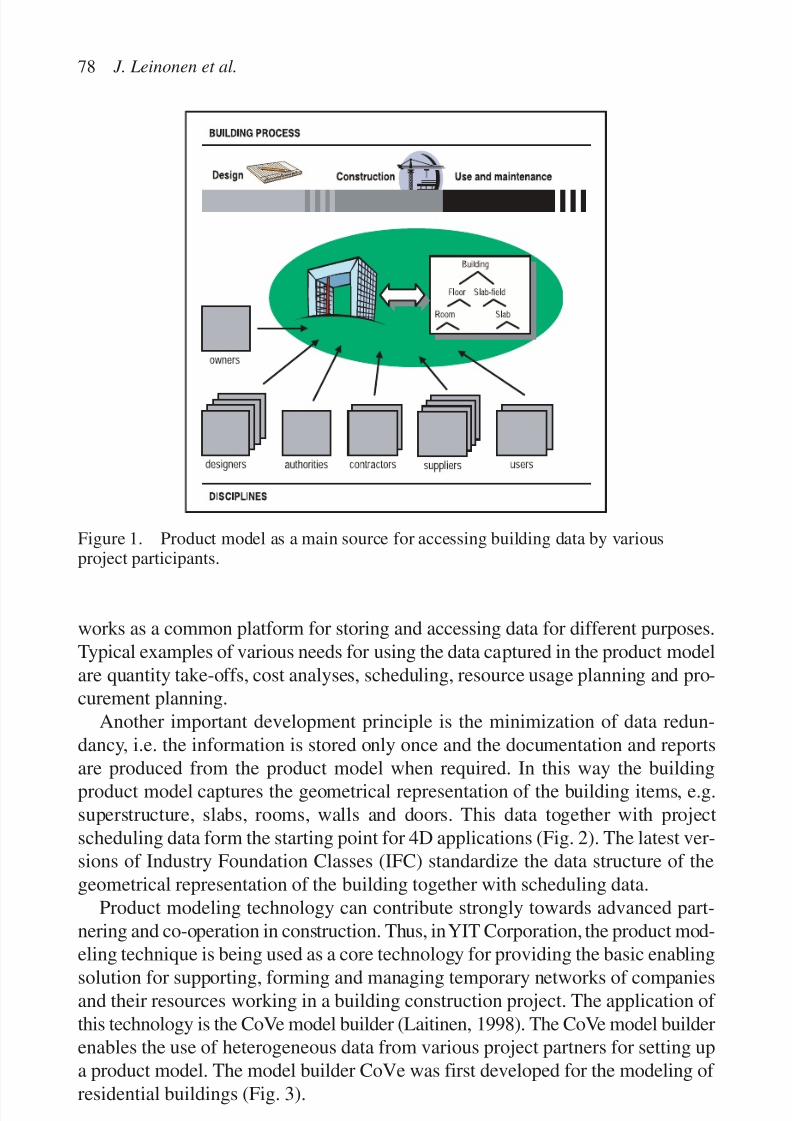
7/14/2019 4DCAD and Visualization in Construction
http://slidepdf.com/reader/full/4dcad-and-visualization-in-construction-56327c6a084e9 87/296
works as a common platform for storing and accessing data for different purposes.Typical examples of various needs for using the data captured in the product modelare quantity take-offs, cost analyses, scheduling, resource usage planning and pro-curement planning.
Another important development principle is the minimization of data redun-dancy, i.e. the information is stored only once and the documentation and reports
are produced from the product model when required. In this way the buildingproduct model captures the geometrical representation of the building items, e.g.superstructure, slabs, rooms, walls and doors. This data together with projectscheduling data form the starting point for 4D applications (Fig. 2). The latest ver-sions of Industry Foundation Classes (IFC) standardize the data structure of thegeometrical representation of the building together with scheduling data.
Product modeling technology can contribute strongly towards advanced part-nering and co-operation in construction. Thus, in YIT Corporation, the product mod-eling technique is being used as a core technology for providing the basic enablingsolution for supporting, forming and managing temporary networks of companiesand their resources working in a building construction project. The application of this technology is the CoVe model builder (Laitinen, 1998). The CoVe model builderenables the use of heterogeneous data from various project partners for setting upa product model. The model builder CoVe was first developed for the modeling of residential buildings (Fig. 3).
78 J. Leinonen et al.
Figure 1. Product model as a main source for accessing building data by variousproject participants.
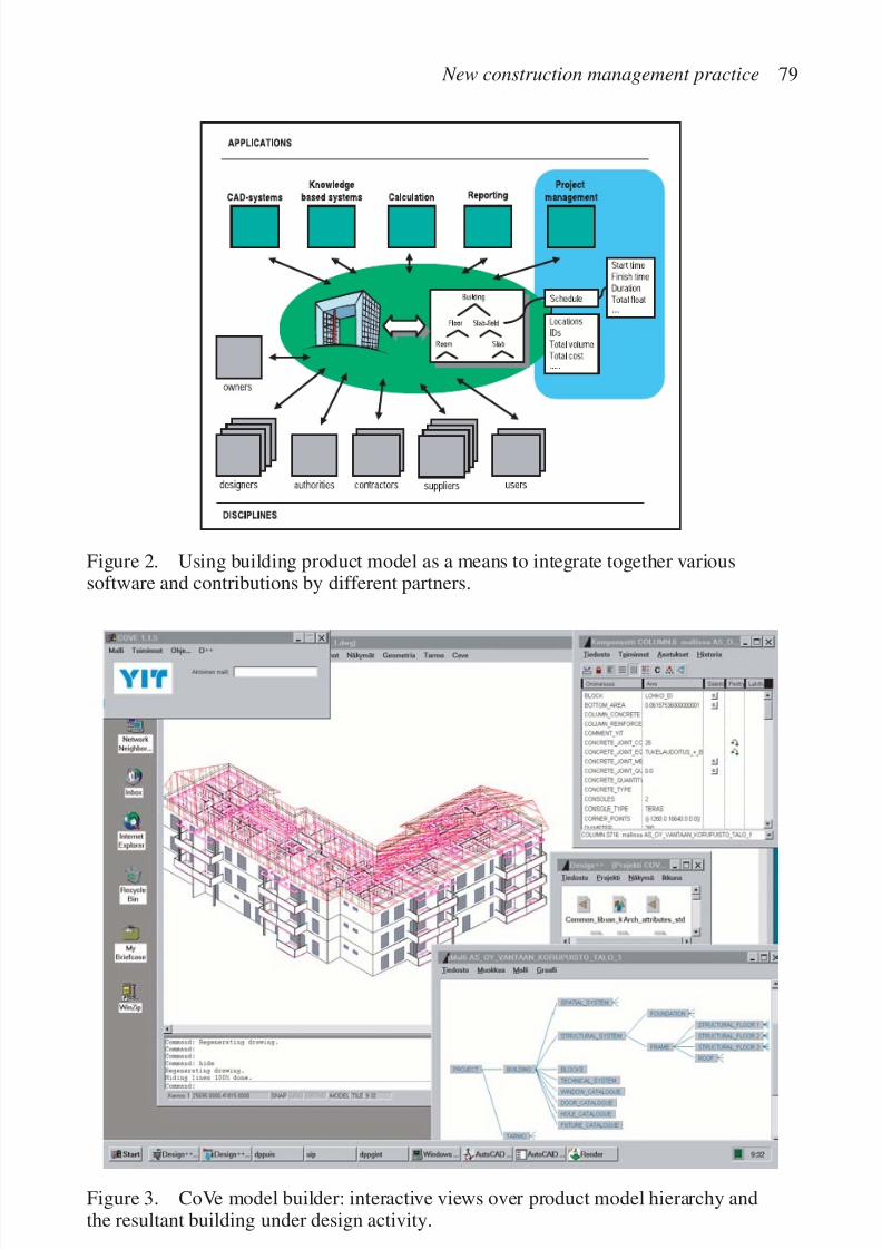
7/14/2019 4DCAD and Visualization in Construction
http://slidepdf.com/reader/full/4dcad-and-visualization-in-construction-56327c6a084e9 88/296
New construction management practice 79
Figure 2. Using building product model as a means to integrate together varioussoftware and contributions by different partners.
Figure 3. CoVe model builder: interactive views over product model hierarchy andthe resultant building under design activity.
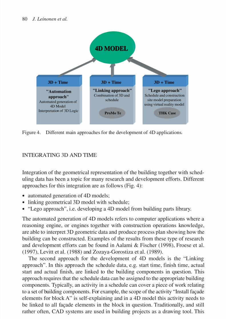
7/14/2019 4DCAD and Visualization in Construction
http://slidepdf.com/reader/full/4dcad-and-visualization-in-construction-56327c6a084e9 89/296
INTEGRATING 3D AND TIME
Integration of the geometrical representation of the building together with sched-uling data has been a topic for many research and development efforts. Differentapproaches for this integration are as follows (Fig. 4):
• automated generation of 4D models;
• linking geometrical 3D model with schedule;
• “Lego approach”, i.e. developing a 4D model from building parts library.
The automated generation of 4D models refers to computer applications where areasoning engine, or engines together with construction operations knowledge,are able to interpret 3D geometric data and produce process plan showing how thebuilding can be constructed. Examples of the results from these type of researchand development efforts can be found in Aalami & Fischer (1998), Froese et al.(1997), Levitt et al. (1988) and Zozaya-Gorostiza et al. (1989).
The second approach for the development of 4D models is the “Linkingapproach”. In this approach the schedule data, e.g. start time, finish time, actual
start and actual finish, are linked to the building components in question. Thisapproach requires that the schedule data can be assigned to the appropriate buildingcomponents. Typically, an activity in a schedule can cover a piece of work relatingto a set of building components. For example, the scope of the activity “Install façadeelements for block A” is self-explaining and in a 4D model this activity needs tobe linked to all façade elements in the block in question. Traditionally, and stillrather often, CAD systems are used in building projects as a drawing tool. This
80 J. Leinonen et al.
3D + Time
"Automation
approach"Automated generation of
4D Model
Interpretation of 3D Logic
3D + Time
"Linking approach"Combination of 3D and
schedule
ProMo Te
3D + Time
"Lego approach"Schedule and construction
site model preparationusing virtual reality model
THK Case
4D MODEL4D MODEL
Figure 4. Different main approaches for the development of 4D applications.

7/14/2019 4DCAD and Visualization in Construction
http://slidepdf.com/reader/full/4dcad-and-visualization-in-construction-56327c6a084e9 90/296
means that designers are not defining objects, such as slab elements, beams, doorsand windows, but they are merely producing a graphical representation of thebuilding using primitive geometric symbols (lines, symbols). This does not pro-
vide possibilities for handling building component concepts, which is a burden forthe development of 4D models. In the following section a research and develop-ment effort combining 3D product model and schedule data is presented. Theresultant ProMoTe tool demonstrates how a 4D model can be used interactively tovisualize data captured in a building product model.
The third approach for the development of 4D models is the “Lego approach”.This approach relies on the interactive study and definition of the buildingconstruction model. The user takes advantage of building parts and resourcelibraries. These libraries are used for setting up a VR model of the planned buildingprocess. In this paper a THK Project case study is presented where this approachwas used for the development of a 4D model.
ProMoTe: LINKING GEOMETRICAL 3D MODEL WITH SCHEDULE
ProMoTe is a product model browser for accessing product model over the Internet
(Hemiö & Hannus, 1999). It provides an effective way to improve the use of prod-uct data technology. ProMoTe retrieves information from various sources andadds it to the product data model. Product data technology (ISO 10303-1 IS, 1994)is proliferating gradually in the facility management and construction industry. Theemerging IFC product data model standard (IAI, 1997) driven by InternationalAlliance for Interoperability (IAI) is gaining wide support. The belief that productmodels are the foundation for information sharing in the future is becoming generallyaccepted. Data transfer in the future will be based more on sharing than sending
(ISO 10303-11 IS, 1994; ISO 10303-21 IS, 1994). The main interest of this paperis the creation of VR models from product data.
Creating virtual reality models with ProMoTeThe user of ProMoTe can create VR models from the whole building model orfrom a part of it. VR models can contain references to other VR models, whichenable the creation of hierarchical sets of models. These models can be created byrequest so that they are always up to date. If the structure of the model supports
content hierarchy specifications, it enables the user to specify different kind of hierarchical VR models for different kinds of purposes in the project.Scheduling data is one essential part of the product model data that can be visual-
ized using VR models. ProMoTe combines a 3D model of a building and schedulingdata originating from project scheduling tool (Microsoft Project) into a 4D-VRMLmodel (Fig. 5; VRML97). ProMoTe retrieves the scheduling data as an exportedfile from the scheduling tool and adds this to the original product data model.
New construction management practice 81
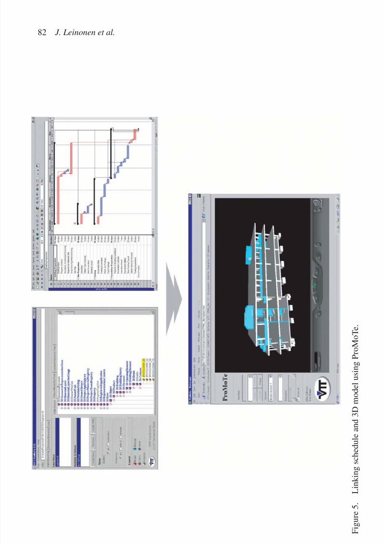
7/14/2019 4DCAD and Visualization in Construction
http://slidepdf.com/reader/full/4dcad-and-visualization-in-construction-56327c6a084e9 91/296
82 J. Leinonen et al.
F i g u r e 5 .
L i n k i n g
s c h e d u l e a n d 3 D m o d e l u s i n g P r o M o T e .

7/14/2019 4DCAD and Visualization in Construction
http://slidepdf.com/reader/full/4dcad-and-visualization-in-construction-56327c6a084e9 92/296
New construction management practice 83
Changes to the schedule are currently done within the scheduling tool. However, atpresent an effort is under way for enabling two-way data traffic. This is supposedto result in a system where the required work breakdown structure (WBS) can be
created in the 3D-VRML model, i.e. a user can group related building parts to formschedule activities. Furthermore, changes to the schedule can be done either in the4D-VRML model or in the MS Project schedule.
Using Virtual Reality Browser as an interface to product data
Virtual Reality Browser (VRB) can be used as an interface to product data, enablingselection of objects and triggering specified methods. Information about the selectedobject, the values of attributes defined for this specific object, can be browsed andthe documents linked to selected object can be studied. Objects can be hidden fromthe VR model and their properties can be changed. For example, in visualization of construction schedule object hiding can be used to simulate construction of thebuilding day by day. Changing the color of the object can be used for highlightingobjects, which are in a conflict, or to visualize changes in the model by showingdifferent versions of objects in different colors.
PROVIDED FUNCTIONALITY
Scheduling
Changing the number of items to be shown can be used to animate the construc-tion process. The user can set the date when the status of the construction processis shown. A slide bar is used to visualize the construction of the building from dayone to the end of the project. This is an efficient technique to examine the con-struction process and especially the space allocations during the process. The VRmodel can also be used for grouping the objects for scheduling. An example of schedule visualization is shown in Figure 6.
Browsing the data relating to a selected object
The values of attributes of selected instance can be browsed (Fig. 7). This enablesan easy validation of the properties of the selected object. Properties are typicallythe material, size and location of the object. Documents (files) can be linked to
selected instances so that all users can immediately see what additional informationis available for this object (Fig. 8). These documents can be anything from thearchitectural specifications of a room to the maintenance log of an air conditioner.
Version comparison
Version comparison is an efficient way to compare two proposals or to view whathas been changed in the model. Models to be compared are displayed in the same
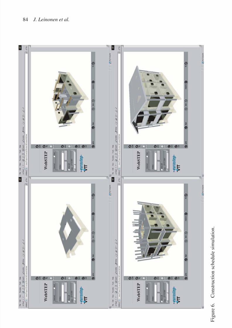
7/14/2019 4DCAD and Visualization in Construction
http://slidepdf.com/reader/full/4dcad-and-visualization-in-construction-56327c6a084e9 93/296
84 J. Leinonen et al.
F i g u r e 6 .
C o n s t r u c t i o n s c h e d u l e s i m u l a t i o n .

7/14/2019 4DCAD and Visualization in Construction
http://slidepdf.com/reader/full/4dcad-and-visualization-in-construction-56327c6a084e9 94/296
New construction management practice 85
Figure 7. Attribute value browser window for looking through the values of attributesrecursively.
Figure 8. Linking desired documents to a certain object in the VR model.

7/14/2019 4DCAD and Visualization in Construction
http://slidepdf.com/reader/full/4dcad-and-visualization-in-construction-56327c6a084e9 95/296
VR model and the user can select the model whose geometry is to be shown. Thisenables switching between the different representations of the selected instance aswell as changing between the whole models. It is also possible to show multiple
representations of the same object at the same time. This is very convenient when theuser wants to compare the alternatives.
Experiences from case studies
Users of ProMoTe have felt that the possibility to visualize and analyze a buildingand its construction in a platform independent of a particular CAD program canenhance significantly project planning and execution. VR models are a user-friendly way to access product data. The possibility to generate models by demandfrom the server using only selected objects makes it efficient also when the data isaccessed through the web. Possibility to define hierarchical VR models using thecontent hierarchy specified by the user into the product model itself, makes it pos-sible to generate different kind of hierarchical models for different purposes.Ability to simulate the construction of the building makes it easier to check thestatus of the work in a specified point of time. Connection to document manage-ment through the objects visualized in the model provides easy access to all doc-uments liked to the model.
4D MODEL FROM BUILDING COMPONENTS ANDRESOURCE LIBRARY
Visualizing construction process
Overview
The intention in this effort was to show the construction of a building visualizingwork progress on a day-to-day basis. The VR based model was devised and devel-oped well in advance to the project completion. It employs a low detail simulationof main superstructure activities involving six basic elements: columns, beams,façade elements, concrete staircases, partitions and hollow slabs.
Case study
The model and simulation are based upon a real construction project in Helsinki.
The operational schedules, element supply table, drawings and photographsfrom the site were used to construct the VR model. The simulation also incorpo-rates the surrounding building site, including familiar site equipment.
The case study addressed the construction process of the THK office buildinglocated close to downtown Helsinki. The premises are owned by The PensionFoundation of the Finnish Broadcasting Company and the main part of the buildingis rented by the Telecommunication Administration Center of Finland (THK). The
86 J. Leinonen et al.

7/14/2019 4DCAD and Visualization in Construction
http://slidepdf.com/reader/full/4dcad-and-visualization-in-construction-56327c6a084e9 96/296
YIT Corporation was the property developer and the main contractor. The totalfloor area of the building is 13,000 m2 and gross volume is 45,000 m3. The totaltime required for the completion of the project was 17 months including the siteactivities, which together with excavation took 14 months (Fig. 9).
METHODOLOGY
The methodology has been built based on previous experience of Virtual Construc-tion Simulation Research Group (VCSRG) at Strathclyde (Retik & Hay, 1994;Retik, 1997; Retik & Shapira, 1999). Though several projects had already beencarried out by the Group, the intention of this project was not only to test existingmethodology by applying it in the real environment, but also to evaluate, with thepractioners involved, the benefits of the approach and technology to constructioncompanies. The visualization was carried out in the following stages:
Stage1: To create the VR based building model in its entirety and surroundingenvironment. This is the most time-consuming part of the visualization. However,the library of virtual elements and virtual plant available from previous projectsfacilitated and shortened the model development.
Stage 2: To determine the work progress, i.e. how much of the building could beconstructed each day. This was calculated from the time schedule produced by theproject manager. Consequently, the building was then divided into groups. Eachtype of element was associated with a separate group. The amount of elementswithin a group is dependent on the above calculation.
Stage 3: Once the above calculation and set up were completed, the programthat controls the simulation was created. At the start of the simulation, the program
New construction management practice 87
Figure 9. Office building in Helsinki for which the VR process simulation model wasdeveloped.
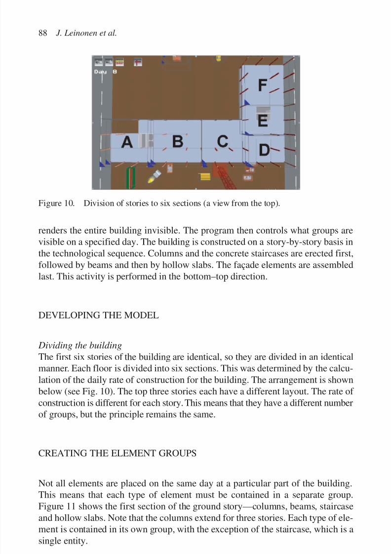
7/14/2019 4DCAD and Visualization in Construction
http://slidepdf.com/reader/full/4dcad-and-visualization-in-construction-56327c6a084e9 97/296
renders the entire building invisible. The program then controls what groups arevisible on a specified day. The building is constructed on a story-by-story basis inthe technological sequence. Columns and the concrete staircases are erected first,followed by beams and then by hollow slabs. The façade elements are assembledlast. This activity is performed in the bottom–top direction.
DEVELOPING THE MODEL
Dividing the building
The first six stories of the building are identical, so they are divided in an identicalmanner. Each floor is divided into six sections. This was determined by the calcu-
lation of the daily rate of construction for the building. The arrangement is shownbelow (see Fig. 10). The top three stories each have a different layout. The rate of construction is different for each story. This means that they have a different numberof groups, but the principle remains the same.
CREATING THE ELEMENT GROUPS
Not all elements are placed on the same day at a particular part of the building.This means that each type of element must be contained in a separate group.Figure 11 shows the first section of the ground story—columns, beams, staircaseand hollow slabs. Note that the columns extend for three stories. Each type of ele-ment is contained in its own group, with the exception of the staircase, which is asingle entity.
88 J. Leinonen et al.
Figure 10. Division of stories to six sections (a view from the top).
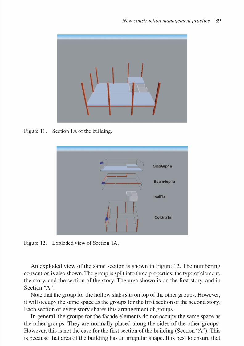
7/14/2019 4DCAD and Visualization in Construction
http://slidepdf.com/reader/full/4dcad-and-visualization-in-construction-56327c6a084e9 98/296
An exploded view of the same section is shown in Figure 12. The numberingconvention is also shown. The group is split into three properties: the type of element,the story, and the section of the story. The area shown is on the first story, and inSection “A”.
Note that the group for the hollow slabs sits on top of the other groups. However,it will occupy the same space as the groups for the first section of the second story.Each section of every story shares this arrangement of groups.
In general, the groups for the façade elements do not occupy the same space asthe other groups. They are normally placed along the sides of the other groups.However, this is not the case for the first section of the building (Section “A”). Thisis because that area of the building has an irregular shape. It is best to ensure that
New construction management practice 89
Figure 12. Exploded view of Section 1A.
Figure 11. Section 1A of the building.
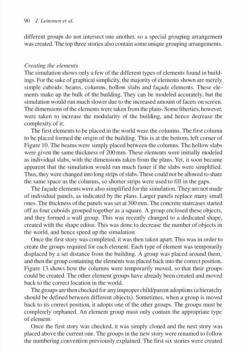
7/14/2019 4DCAD and Visualization in Construction
http://slidepdf.com/reader/full/4dcad-and-visualization-in-construction-56327c6a084e9 99/296
different groups do not intersect one another, so a special grouping arrangementwas created. The top three stories also contain some unique grouping arrangements.
Creating the elements
The simulation shows only a few of the different types of elements found in build-ings. For the sake of graphical simplicity, the majority of elements shown are merelysimple cuboids: beams, columns, hollow slabs and façade elements. These ele-ments make up the bulk of the building. They can be modeled accurately, but thesimulation would run much slower due to the increased amount of facets on screen.The dimensions of the elements were taken from the plans. Some liberties, however,were taken to increase the modularity of the building, and hence decrease thecomplexity of it.
The first elements to be placed in the world were the columns. The first columnto be placed formed the origin of the building. This is at the bottom, left corner of Figure 10. The beams were simply placed between the columns. The hollow slabswere given the same thickness of 200 mm. These elements were initially modeledas individual slabs, with the dimensions taken from the plans. Yet, it soon becameapparent that the simulation would run much faster if the slabs were simplified.Thus, they were changed into long strips of slabs. These could not be allowed to share
the same space as the columns, so shorter strips were used to fill in the gaps.The façade elements were also simplified for the simulation. They are not made
of individual panels, as indicated by the plans. Larger panels replace many smallones. The thickness of the panels was set at 300 mm. The concrete staircases startedoff as four cuboids grouped together as a square. A group enclosed these objects,and they formed a wall group. This was recently changed to a dedicated shape,created with the shape editor. This was done to decrease the number of objects inthe world, and hence speed up the simulation.
Once the first story was completed, it was then taken apart. This was in order tocreate the groups required for each element. Each type of element was temporarilydisplaced by a set distance from the building. A group was placed around them,and then the group containing the elements was placed back into the correct position.Figure 13 shows how the columns were temporarily moved, so that their groupscould be created. The other element groups have already been created and movedback to the correct location in the world.
The groups are then checked for any improper child/parent adoptions (a hierarchy
should be defined between different objects). Sometimes, when a group is movedback to its correct position, it adopts one of the other groups. The groups must becompletely orphaned. An element group must only contain the appropriate typeof element.
Once the first story was checked, it was simply cloned and the next story wasplaced above the current one. The groups in the new story were renamed to followthe numbering convention previously explained. The first six stories were created
90 J. Leinonen et al.

7/14/2019 4DCAD and Visualization in Construction
http://slidepdf.com/reader/full/4dcad-and-visualization-in-construction-56327c6a084e9 100/296
this way. The top three stories were also created in a similar way, but with differentnumbers and sizes of groups.
THE SIMULATION PROGRAM
The code for the simulation can be classified into three different types: the main
code, the icon code and background code. They are all interconnected, by passingcounter values to each other.
The main code controls the simulation of the building. It decides what sectionsof the building to display on a given day. The main code also decides what icons andinstruments are enabled on the screen display. The code is attached to the “Anchor”object. This is disguised as a portacabin in the VR world (from viewpoint 4, it isvisible in the bottom right corner of the screen). The main code is by far the largestcode in the simulation.
The icon code is used to pass control data to the main program. It is also usedto control some of the vehicles in the world, both directly and indirectly. Many of
the icons are unavailable at certain times during the simulation. Their availabilityis controlled by the main code. The icons process the SCL User Functions.The background code is attached to various objects in the world. Some of the
objects, like parts of the tower crane, communicate with the icon code and the maincode. The cars that travel on the roads around the world have their own predeter-mined paths. These are controlled by their own code. They have no connection tothe icon code, or the main code.
New construction management practice 91
Figure 13. Creating column groups.

7/14/2019 4DCAD and Visualization in Construction
http://slidepdf.com/reader/full/4dcad-and-visualization-in-construction-56327c6a084e9 101/296
USING THE MODEL
Once the simulation scenario is built in, the construction process can be simulatedday-by-day (see Fig. 14) by pressing the forward or backward arrow icons on thescreen (see left corner, first image, of Fig. 14). The user can stop simulation any-where or select to “jump” to any day he/she wants to explore the project at anyparticular time. The exploration can be done interactively by walking through orby changing views (see Fig. 15).
92 J. Leinonen et al.
Figure 14. Time-based simulation.
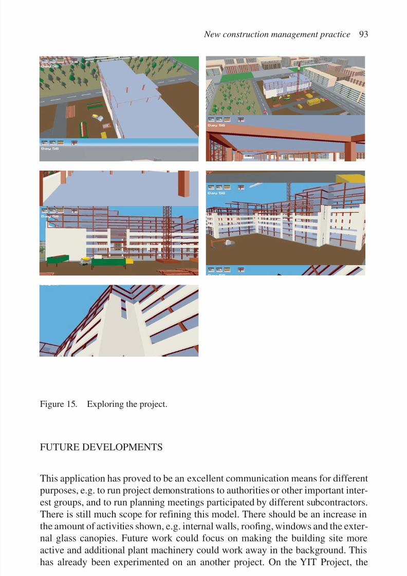
7/14/2019 4DCAD and Visualization in Construction
http://slidepdf.com/reader/full/4dcad-and-visualization-in-construction-56327c6a084e9 102/296
New construction management practice 93
Figure 15. Exploring the project.
FUTURE DEVELOPMENTS
This application has proved to be an excellent communication means for differentpurposes, e.g. to run project demonstrations to authorities or other important inter-est groups, and to run planning meetings participated by different subcontractors.There is still much scope for refining this model. There should be an increase inthe amount of activities shown, e.g. internal walls, roofing, windows and the exter-nal glass canopies. Future work could focus on making the building site moreactive and additional plant machinery could work away in the background. Thishas already been experimented on an another project. On the YIT Project, the
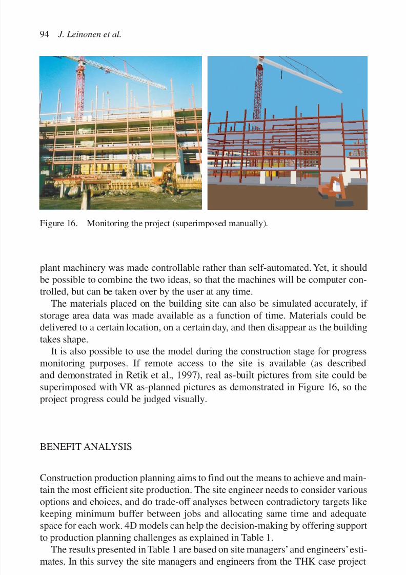
7/14/2019 4DCAD and Visualization in Construction
http://slidepdf.com/reader/full/4dcad-and-visualization-in-construction-56327c6a084e9 103/296
plant machinery was made controllable rather than self-automated. Yet, it shouldbe possible to combine the two ideas, so that the machines will be computer con-trolled, but can be taken over by the user at any time.
The materials placed on the building site can also be simulated accurately, if storage area data was made available as a function of time. Materials could bedelivered to a certain location, on a certain day, and then disappear as the buildingtakes shape.
It is also possible to use the model during the construction stage for progressmonitoring purposes. If remote access to the site is available (as describedand demonstrated in Retik et al., 1997), real as-built pictures from site could besuperimposed with VR as-planned pictures as demonstrated in Figure 16, so the
project progress could be judged visually.
BENEFIT ANALYSIS
Construction production planning aims to find out the means to achieve and main-
tain the most efficient site production. The site engineer needs to consider variousoptions and choices, and do trade-off analyses between contradictory targets likekeeping minimum buffer between jobs and allocating same time and adequatespace for each work. 4D models can help the decision-making by offering supportto production planning challenges as explained in Table 1.
The results presented in Table 1 are based on site managers’and engineers’esti-mates. In this survey the site managers and engineers from the THK case project
94 J. Leinonen et al.
Figure 16. Monitoring the project (superimposed manually).
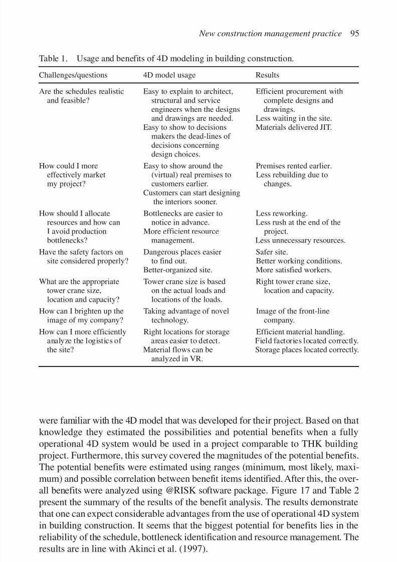
7/14/2019 4DCAD and Visualization in Construction
http://slidepdf.com/reader/full/4dcad-and-visualization-in-construction-56327c6a084e9 104/296
New construction management practice 95
Table 1. Usage and benefits of 4D modeling in building construction.
Challenges/questions 4D model usage Results
Are the schedules realistic Easy to explain to architect, Efficient procurement withand feasible? structural and service complete designs and
engineers when the designs drawings.and drawings are needed. Less waiting in the site.
Easy to show to decisions Materials delivered JIT.makers the dead-lines of decisions concerningdesign choices.
How could I more Easy to show around the Premises rented earlier.effectively market (virtual) real premises to Less rebuilding due tomy project? customers earlier. changes.
Customers can start designingthe interiors sooner.
How should I allocate Bottlenecks are easier to Less reworking.resources and how can notice in advance. Less rush at the end of theI avoid production More efficient resource project.bottlenecks? management. Less unnecessary resources.
Have the safety factors on Dangerous places easier Safer site.site considered properly? to find out. Better working conditions.
Better-organized site. More satisfied workers.
What are the appropriate Tower crane size is based Right tower crane size,
tower crane size, on the actual loads and location and capacity.location and capacity? locations of the loads.
How can I brighten up the Taking advantage of novel Image of the front-lineimage of my company? technology. company.
How can I more efficiently Right locations for storage Efficient material handling.analyze the logistics of areas easier to detect. Field factories located correctly.the site? Material flows can be Storage places located correctly.
analyzed in VR.
were familiar with the 4D model that was developed for their project. Based on thatknowledge they estimated the possibilities and potential benefits when a fullyoperational 4D system would be used in a project comparable to THK buildingproject. Furthermore, this survey covered the magnitudes of the potential benefits.The potential benefits were estimated using ranges (minimum, most likely, maxi-
mum) and possible correlation between benefit items identified. After this, the over-all benefits were analyzed using @RISK software package. Figure 17 and Table 2present the summary of the results of the benefit analysis. The results demonstratethat one can expect considerable advantages from the use of operational 4D systemin building construction. It seems that the biggest potential for benefits lies in thereliability of the schedule, bottleneck identification and resource management. Theresults are in line with Akinci et al. (1997).
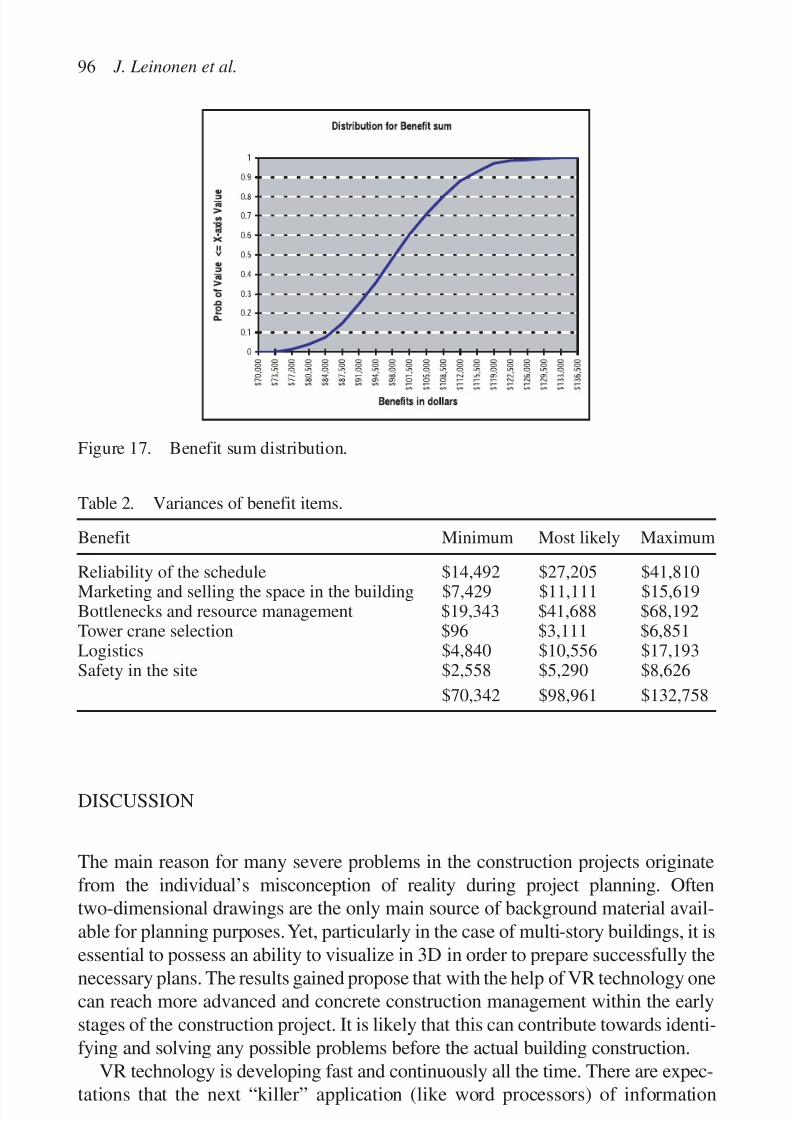
7/14/2019 4DCAD and Visualization in Construction
http://slidepdf.com/reader/full/4dcad-and-visualization-in-construction-56327c6a084e9 105/296
DISCUSSION
The main reason for many severe problems in the construction projects originatefrom the individual’s misconception of reality during project planning. Oftentwo-dimensional drawings are the only main source of background material avail-able for planning purposes. Yet, particularly in the case of multi-story buildings, it is
essential to possess an ability to visualize in 3D in order to prepare successfully thenecessary plans. The results gained propose that with the help of VR technology onecan reach more advanced and concrete construction management within the earlystages of the construction project. It is likely that this can contribute towards identi-fying and solving any possible problems before the actual building construction.
VR technology is developing fast and continuously all the time. There are expec-tations that the next “killer” application (like word processors) of information
96 J. Leinonen et al.
Figure 17. Benefit sum distribution.
Table 2. Variances of benefit items.
Benefit Minimum Most likely Maximum
Reliability of the schedule $14,492 $27,205 $41,810Marketing and selling the space in the building $7,429 $11,111 $15,619Bottlenecks and resource management $19,343 $41,688 $68,192Tower crane selection $96 $3,111 $6,851Logistics $4,840 $10,556 $17,193Safety in the site $2,558 $5,290 $8,626
$70,342 $98,961 $132,758

7/14/2019 4DCAD and Visualization in Construction
http://slidepdf.com/reader/full/4dcad-and-visualization-in-construction-56327c6a084e9 106/296
technology will be based on the VR technology. Progressive companies can already
start to apply the current VR technology and gain advantages from it. However,widespread applications are set to emerge in the near future.
Augmented reality
Augmented reality is combination of a 4D model and a telepresence stream. Tele-presence is a technology that provides a possibility to feel present in a remotelocation, usually with the help of a digital video camera. Applying augmentedreality, a 4D model and telepresence image can be viewed together and synchro-
nized in a way that the user can easily compare the planned schedule and actualperformance (Retik et al., 1997). In addition, the 4D model could be used as apointing device for telepresence equipment. To receive additional information insome detail on site the user only needs to point the place on a 4D model. The tele-presence equipment would then provide the appropriate video stream from site orvia model details where further information can be accessed, i.e. some documentslinked to the details, see Figure 18.
CONCLUSIONS
The main efforts for integrating 3D and time can be classified according to threedifferent approaches. These are automated generation of 4D models, linking a 3Dmodel with schedule and the “Lego approach”. The authors’main conclusions from
New construction management practice 97
Figure 18. Augmented reality demonstration. A telepresence video stream fromconstruction site and VR image combined (project in September 1997).

7/14/2019 4DCAD and Visualization in Construction
http://slidepdf.com/reader/full/4dcad-and-visualization-in-construction-56327c6a084e9 107/296
the case studies on linking 3D model with schedule and applying the “Legoapproach” are as follows:
• Product data access using VR models can cover both viewing and product data
editing. This can considerably improve the possibilities of construction practi-tioners to take advantage of modern information technology.
• Integration of 4D scheduling with the companies’ working practice enables newimproved planning processes having clear potential for significant benefits. Thebenefits are mainly due to improved communication making it possible to getother necessary people, e.g. subcontractors, material suppliers and representa-tives of client, involved in schedule preparation and analysis.
It is obvious that first widespread 4D applications in construction shall coverlinking the 3D product model with scheduling data and possibilities for viewing theplanned construction process. For reaching this the research and development effortsshould be more focused on case studies and piloting where construction practition-ers try to apply the prototype tools by themselves. Detailed virtual construction sitesare an interesting research topic from which some very useful new planning andanalysis techniques can arise to be used in practice, e.g. machinery selection andusage planning, site logistics planning and analysis of hazardous situations.
REFERENCES
Aalami, F. & Fischer, M. 1998. Joint product and process model elaboration based onconstruction method models. In B.-C. Björk & A. Jädbeck (eds), The life-cycle of IT innovations in construction—Technology transfer from research to practice.Proceedings of CIB78 conference, 5–8 June, Stockholm. Sweden: Royal Institute of Technology.
Akinci, B., Staub, A. & Fischer, M. 1997. Productivity and cost analysis based on a 4Dmodel. In R. Drogemuller (ed.), Information technology support for construction process reengineering, CIB Publication 208. Australia: James Cook University of North Queensland.
Alshawi, M. 1996. Virtual reality: future implication on construction. Proceeding of thesecond international conference in civil engineering on computer applicationsresearch and practice, Vol. 2, Bahrain, April: 789–795.
Barkley, B.T. & Saylor, J.H. 1994. Customer driven project management. USA: McGrow-Hill Inc.
Björk, B.-C. 1995. Requirements and information structures for building product datamodels, VTT Publications 245. Espoo: Technical Research Centre of Finland.Froese, T., Rankin, J. & Yu, K. 1997. Project management application models and
computer-assisted construction planning in total project systems. International Journalof Construction Information Technology 5(1): 39–62.
Goldstein, H. 1995. Is virtual reality for real? Civil Engineering June 1995: 45–48.IAI. 1997. IFC object model for AEC projects. IFC Release 1.5 Model Reference
Documentation, Final Version. Washington, DC: IAI Publ.
98 J. Leinonen et al.

7/14/2019 4DCAD and Visualization in Construction
http://slidepdf.com/reader/full/4dcad-and-visualization-in-construction-56327c6a084e9 108/296
ISO 10303-1 IS. 1994. Product data representation and exchange—Part 1: Overview and fundamental principles. ISO TC 184/SC4, Geneva.
ISO 10303-11 IS. 1994. Product data representation and exchange—Part 11: Descriptionmethods: The EXPRESS language reference manual. ISO TC 184/SC4, Geneva.
ISO 10303-21 IS. 1994. Product data representation and exchange—Part 21: Implementa-tion methods: Clear text encoding of the exchange structure. ISO TC 184/SC4, Geneva.
Josephson, P. & Hammarlund,Y. 1996. Kvalitetsfelkostnader på 90-talet—en studie av sjubyggnadsproject (Quality defect costs during ninetees). Del 1, Report 49, ChalmersUniversity of Technology, Gothenburg, Sweden.
Koskela, L. 2000. En exploration towards a production theory and its application toconstruction. Espoo, Finland: VTT Publications.
Laitinen, J. 1998. Model based construction process management. Ph.D. Dissertation,Royal Institute of Technology, Stockholm, Sweden.
Levitt, R.E., Kartam, N.A. & Kunz, J.C. 1988. Artificial intelligence techniques forgenerating construction project plans. Journal of Construction Engineering and Management 114(3): 329–343.
Ogata, S., Kobayashi, I. & Fukuchi, Y. 1998. Application of virtual model to achieveconsensus for construction project. Proceedings of the first international conference onnew information technologies for decision making in civil engineering. Ecole detechnologie supérieve, Université du Québec, Montréal, Canada: 1217–1226.
Retik, A. & Hay, R. 1994. Visual simulation using VR. Proceedings of the 10th ARCOM conference, Loughborough, September: 537–546 .
Retik, A. 1997. Planning and monitoring of construction projects using virtual reality.
Journal of Project Management (APMF) 3: 28–32.Retik, A., Clark, N., Fryer, R., Hardiman, R., McGregor, G., Mair, G., Retik, N. &Revie, K. 1997. Mobile hybrid virtual reality and telepresence for planning and monitor-ing of engineering projects. Proceedings of the 4th UK virtual reality interest groupconference, Brunel University: 80–89.
Retik,A. & Shapira,A. 1999. VR based planning of construction site activities. Automationin Construction: 671–680.
Turner, R.J. 1993. The handbook of project-based management. McGraw-Hill Book C.VRML97. 1997. The virtual reality modeling language. ISO/IEC 14772-1:1997. http://
www.vrml.org/technicalinfo/specifications/vrml97/
Zozaya-Gorostiza, C., Hendrickson, C. & Rehak, D.R. 1989. Knowledge-based process planning for construction and manufacturing. USA: Academic Press Inc.
FURTHER READINGS
APM. 1996. Body of knowledge. United Kingdom: Association for Project Management.Hemiö, T. & Hannus, M. 1999. Implementing browsing tool for EXPRESS schemata and
STEP data. Proceedings of product data technology Europe 1999, Stavanger, Norway.http://cic.vtt.fi/rtetjh/Promote/ (papers).
New construction management practice 99

7/14/2019 4DCAD and Visualization in Construction
http://slidepdf.com/reader/full/4dcad-and-visualization-in-construction-56327c6a084e9 109/296

7/14/2019 4DCAD and Visualization in Construction
http://slidepdf.com/reader/full/4dcad-and-visualization-in-construction-56327c6a084e9 110/296
4D CAD AND DYNAMIC RESOURCE PLANNING FORSUBCONTRACTORS: CASE STUDY AND ISSUES
William J. O’Brien
M. E. Rinker, Sr. School of Building Construction,
University of Florida, Gainesville, FL, USA
101
Abstract
Even in a world with widespread use of 4D CAD, changes in schedule and scope will
remain a salient feature of construction projects. This paper discusses an extension of 4D
CAD techniques to improve subcontractor cost and resource planning in a dynamic envi-
ronment. As a basis for multi-project development of 4D CAD, this paper presents adetailed case study of a subcontractor’s resource management challenges, and from this
develops a conceptual model for multi-project management at the subcontractor level.
This empirical and theoretical groundwork supports a critique of current 4D CAD tools
that are limited to a single project perspective. 4D tools must be extended to integrate
detailed planning on individual projects into the multi-project resource allocation process.
An extension to a multi-project environment will allow subcontractors to better plan for
changes in schedule and scope as well as accommodate them when they do occur. The pro-
posed extensions have additional benefits. They allow detailed cost accounting of the ram-
ifications of changes and hence improve the ability to negotiate compensation for thosechanges. More broadly, they allow evaluation of project schedules from the perspective of
subcontractor ability to adjust to changes. This promises applications of 4D CAD that
promote both efficiency and flexibility.
Keywords: 4D CAD, subcontractors, construction costs, resource planning, cost planning
INTRODUCTION
It is no great insight to note that how a subcontractor’s management operates itsresources is a key factor in firm success. Nor is it a great insight to note that sub-contractors work on multiple projects concurrently. Yet relatively little literature
7/14/2019 4DCAD and Visualization in Construction
http://slidepdf.com/reader/full/4dcad-and-visualization-in-construction-56327c6a084e9 111/296
exists to help subcontractors manage their resources beyond the productivityimprovement literature for individual activities. There is a complete lack of toolsthat relate a subcontractor’s resource allocation across projects to cost (O’Brien &
Fischer, 2000). Costing methods follow the assumptions of network schedulingmethods, focusing on costs of individual activities and of single projects. Noallowance is made for interaction between projects. Yet subcontractors emphati-cally do manage their resources from a multi-project perspective, taking a varietyof actions to optimize resource allocation across projects in the face of changingconditions.
Costs to subcontractors in a multi-project context occur because of changes inproject schedule and scope. If changes did not occur, subcontractors and supplierscould predictably allocate their capacity (resources) to projects and they wouldnot suffer any capacity related costs. (Further, bidding would ensure an efficientallocation of capacity across firms (see O’Brien et al., 1995 for further discussion)).However, changes in schedule are a common occurrence on construction projects.The causes of such changes are numerous and well cataloged in the constructionliterature: weather, owner directed changes, problems with permitting, unexpectedsoil conditions, materials delays, accelerations, rework that affects schedule, coordi-nation difficulties, etc.
In one sense, existing 3D and 4D CAD tools are an attempt to control the inci-
dence of changes on construction sites. 3D/4D tools improve designs, reduce theincidence of time and space conflicts on construction sites, improve the materialsflow, and improve schedule reliability. Thus 3D/4D tools may reduce the numberof changes on project sites and therefore improve subcontractors’ ability to plantheir resource allocation across projects. But it is the nature of projects to bedynamic; while generating one set of improved capabilities, 3D/4D tools do notremove the changes in project schedule and scope from influences such as weather.Moreover, the capability of 3D/4D tools in design may make owners more rather
then less likely to initiate changes, particularly in a business environment thatdemands speed and flexibility.
Changes to projects are given, and thus subcontractors will continue to facemulti-project resource management challenges. Unfortunately, existing 3D/4Dtools lack a multi-project perspective, having been developed in a single projectcontext. These tools do not aid a subcontractor in its resource management andmay in some cases hinder it. For example, many 4D models make assumptionsthat resources are fixed or that there is costless flexibility in assigning resources.
Other 4D models that automate schedules assume that methods direct resources,and assign subcontractor resources based on methods and schedule needs. Yet formany subcontractors, it is the availability of resources that influences the choiceof methods and staffing needs on a job site. Thus the real-world considerations of subcontractors may be in direct conflict with the virtual dictates of a 4D model.
This paper discusses extensions of 3D/4D modeling methods to subcontrac-tors’ multi-project resource management needs. A case study of the progressive
102 W.J. O’Brien

7/14/2019 4DCAD and Visualization in Construction
http://slidepdf.com/reader/full/4dcad-and-visualization-in-construction-56327c6a084e9 112/296
subcontractor Pacific Contracting provides details of the constraints and consider-ations a subcontractor makes when making resource allocation decisions in a multi-project environment. From the case findings, a conceptual basis for multi-project
resource management and costing is presented, allowing definition of severalquestions pertinent to subcontractor resource management. These provide a foun-dation for examination of current capabilities in 3D/4D CAD and discussion of extensions. In particular, there needs to be development of 4D tools that automat-ically assess the affects of resource re-allocations on project performance andripple effects across projects.
PACIFIC CONTRACTING PART ONE: RESOURCEMANAGEMENT PROBLEMS
The Pacific Contracting case study presented in this section is an intimate descrip-tion of how a subcontractor manages its business, particularly with regard to man-agement policies in relation to site conditions and resource allocation. Such a viewof subcontractors is largely absent from the construction literature. One explana-
tion for this lack of literature about subcontractors is the arm’s length relationshipsthat exist between subcontractors and general contractors. Subcontractors arethere to provide a contractual service. Hence, the extant literature on procurementand contracting serves as a substitute for a more specific literature about subcon-tractors. Discussion of the relative merits of contracts and incentives can be foundin Abu-Hijleh & Ibbs (1989), Ashley & Workman (1986), Griffis & Butler (1988),Stukhart (1984) and Uher (1991). This literature does provide a useful way tostructure and understand relationships and, of course, contracts are a necessaryaspect of business practice. However, none of this literature explicitly considersthe production choices facing subcontractors or their internal cost drivers.
Some literature provides a macro-level view of the conditions facing sub-contractors (Gray & Flanagan, 1989; Bennett & Ferry, 1990) or focuses on thecontractor–subcontractor relationship (Hinze & Tracey, 1994) rather than on internalsubcontractor policies. While none of this literature details resource managementpolicies at the operations level, there are several points of agreement between theliterature and the Pacific Contracting case study that suggests Pacific Contractingis a common example of its genre. One point common among all the authors is
that subcontractors are commonly subject to changing conditions with poor man-agement by general contractors. In a review of subcontracting in the UnitedKingdom, Bennett & Ferry (1990: 271) note that:
… under construction management contracts, and to a greater extent undermanagement contracting, the specialists are just thrown together and told tosort things out by themselves.
4D CAD and dynamic resource planning for subcontractors 103
7/14/2019 4DCAD and Visualization in Construction
http://slidepdf.com/reader/full/4dcad-and-visualization-in-construction-56327c6a084e9 113/296
Another point of agreement is that subcontractors generally try to take mattersinto their own hands in attempt to better control their fate under the vagaries of changing site conditions and schedule. Hinze & Tracey (1994) concluded in a
United States-based study of the contractor–subcontractor relationship that sub-contractors often act autonomously of general contractors to smooth executionof their project obligations. Gray & Flanagan (1989) note that subcontractors areincreasing their involvement in the design stage to improve productivity andshield themselves from disruption on-site due to poorly coordinated design; this isa strategy Pacific Contracting makes aggressive use of. More generally, Bennett &Ferry (1990) describe how successful subcontractors actively maintain a core setof skills and capabilities that they protect by established boundary control sys-tems. Such boundary systems buffer production workers from disruption, some-thing Pacific Contracting attempts to do in its planning process. Unfortunately, noamount of buffering can fully shield a subcontractor’s resources from varying siteconditions affecting productivity or from changes in schedule. As such, the PacificContracting study below details not just the strategies used to avoid disruption butalso how the firm responds to changes in site conditions and schedule which affectresource productivity and deployment.
OVERVIEW
A small roofing subcontractor working primarily in the California Bay Area,Pacific Contracting bills approximately US $5 m a year. As a young and growingfirm, Pacific Contracting (Pacific) has sought to use technology and best-practicemanagement methods to improve productivity and quality and therefore enhancemarket position. Currently, Pacific has formed an alliance with a major general
contractor to become the general’s preferred supplier of roofing on the WestCoast. Pacific’s long-term strategic plan is to become a “skin contractor” thatorganizes and controls the erection of the exterior walls and roof of a building. Infull realization of its growth plans, the firm will provide engineering services fordesign, detailing, and value engineering; these engineering services will supportand improve the construction capabilities of the firm and its suppliers.
Pacific Contracting’s strategic plan is largely a response to conditions of siteconstruction. In their work, Pacific’s management has observed that interaction
between trades on-site is often poorly coordinated and that design information isoften incomplete and/or the project is difficult to build as designed. These prob-lems delay or otherwise interrupt the progress of work on-site, increasing directcosts for Pacific as well as decreasing its ability to predict and level demand forresources across jobs, leading to a series of indirect costs. As a roofing firm,Pacific is often in the position of doing its work after other firms, subjecting themto the aftereffects of the problems of others. At the same time, roofing is usually a
104 W.J. O’Brien
7/14/2019 4DCAD and Visualization in Construction
http://slidepdf.com/reader/full/4dcad-and-visualization-in-construction-56327c6a084e9 114/296
critical path item because of the need to make the building watertight for interiorwork; this places Pacific under enormous pressure to complete their work on-schedule even if there were delays caused by others.
RESOURCE MANAGEMENT PROBLEMS
The reality of construction sites is that trades closely follow each other. If they arepoorly scheduled or if production slows, Pacific crews can be kept waiting, work-ing unproductively in a start-stop fashion, subject to the progress of others. Pacifichas also found that because of pressures to complete the overall project as quicklyas possible, general contractors will attempt to get subcontractors to start on-siteas early as possible. This leads to a condition known as “trade stacking” wheremultiple trades follow each other closely and, like dominoes, if one trade fallsprey to difficulty, all are affected.
In particular, Pacific finds itself subject to both poor scheduling and work areacoordination among trades. Start and end dates for scheduled work are uncertain,and site conditions are not conducive to productive work. These two problems areintimately linked and comprise the biggest challenge to profitable allocation of
Pacific’s resources. Pacific has a fixed group of workers and site superintendents.To maintain productivity, projects should be scheduled such that all workers arefully employed at all times. The implication of this is that workers should finish oneproject and move directly to another. Unproductive site conditions, because theycannot be fully anticipated and may vary over the course of a project, lead directlyto uncertain end dates (and hence, uncertain start dates for the next project), mak-ing it difficult for Pacific to maintain constant and level use of its work force.
RESPONSES TO RESOURCE MANAGEMENT PROBLEMS:INFLUENCES AND CONSIDERATIONS
Pacific maintains a number of degrees of freedom in the deployment of its (finite)resources. However, these are subject to a number of constraints and considera-tions, including site conditions, the nature of the work underway, worker skills,
and the availability of resources. Profitability considerations, relationship manage-ment, contractual conditions, and upcoming project commitments also constitutemeaningful constraints on Pacific’s actions. These various influences constitute acomplex environment that Pacific manages heuristically, seeking its most prof-itable allocation of resources in an environment that changes daily. Major influ-ences on Pacific’s resource allocation and profitability are detailed below, togetherwith policies that Pacific has adopted to manage in response to these influences.
4D CAD and dynamic resource planning for subcontractors 105
7/14/2019 4DCAD and Visualization in Construction
http://slidepdf.com/reader/full/4dcad-and-visualization-in-construction-56327c6a084e9 115/296
Site conditions
Poor site conditions comprise the biggest threat to Pacific’s worker productivityand profitability. Ideally, when Pacific begins to work on a project, all prerequisite
work has been completed, materials are available and accessible, access routesand work areas are clear and clean, and hoisting equipment is readily available.The most important of these is the completion of all prerequisite work. If work isincomplete, Pacific’s work is impacted in three ways: first, through the necessityof work arounds; second, through increased coordination requirements with othersubcontractors; and, third, through diminished work area. In the first case, if work has not been performed, then Pacific must work around the unfinished areas, low-ering worker productivity in the first pass and in the necessary second pass tocomplete the affected area. Such work arounds also make meeting completiondates difficult, which can lead to conflicting demands on resources as well asincreased liabilities. This leads to the second problem of unfinished prerequisitework: other subcontractors must make multiple passes, requiring increased coor-dination between those subcontractors and Pacific. Because other subcontractorshave already completed a first pass, they may not readily have resources availablefor a second pass and will keep Pacific waiting. Further, on subsequent passes,subcontractors may damage materials that Pacific has installed. This is especiallyworrisome given the delicacy of roofing membranes and the liability Pacific
assumes in the case of leaks.The third difficulty of incomplete prerequisite work is altered or diminished work
areas. Proper sizing of work areas gives Pacific the ability to sequence and structurework for maximum productivity. In the simplest case, Pacific follows the work of others in a linear fashion and there must be a large enough buffer between tradessuch that there is no interference from random fluctuations in production rate (and,hopefully, a large enough buffer to provide some protection against work stop-pages). More commonly, Pacific inherits an area of work from a preceding subcon-
tractor. When finished, Pacific releases that area to a following trade and moves onto the next area. Size and sequence of work areas or packages are often determinedby the general contractor’s plan for completion of the facility. Where possible,Pacific will negotiate with the general to sequence and size work areas in an optimalmanner for Pacific’s worker productivity. About 80% of Pacific’s work is negotiatedin the sense that the overall and the particulars of schedule are discussed.
Pacific plans its work very carefully; after the building is divided into multiplework areas or work packages, a bill of materials is determined for each. Pacific then
sequences its work within each work area, determining the order in which to laydown the multiple layers of membranes or surfaces, the flashing around the roof edges and penetrations, etc. Resource requirements are determined from the vol-ume and type of work in the work packages, the sequence of the work to be done,and the completion dates of each package. Reference is also made to Pacific’s over-all resource commitments. This aggressive planning serves to maximize workerproductivity in each work package. However, work areas smaller than planned for
106 W.J. O’Brien

7/14/2019 4DCAD and Visualization in Construction
http://slidepdf.com/reader/full/4dcad-and-visualization-in-construction-56327c6a084e9 116/296
make it difficult for Pacific to sequence its work effectively in that area. This isexacerbated if the physical space allotted to the crew is too small for them to beproductive; below a certain size Pacific finds that crews just cannot be efficient.
Nature of the work and worker skills
The severity of resource and productivity problems relating to site conditions isclosely related to the nature of the work at hand and the skill of Pacific’s workers.For example, some kinds of work are very sensitive to sequencing concerns whileothers are not (this extends to setting up an area for work as well as performing thework). Likewise, some kinds of work are very flexible in staffing requirementswhile others are not. Laying tile, e.g. can be done in small teams and is an activitythat can be rapidly scaled up or down. Laying roofing membranes is a less flexibleactivity where there is a definite crew size and may also be physically constrained,e.g. a specific area must be covered in a single pass to ensure continuity. One strat-egy that Pacific uses to balance demand for resources is to shift them betweenprojects; thus rather than work at lower productivity due to smaller work area,Pacific may pull its workers from one project and place them on others. Its abilityto do this, of course, is determined heavily by the nature of the work underway.Together with current backlog available to be worked, the type of work determinesthe ability of a project to absorb (or loan) resources.
In practice, Pacific shifts workers (and less frequently, other resources such asequipment) between projects on a weekly and sometimes daily basis. Currently,site superintendents and project managers determine resource re-allocations. Theydetermine the project needs for the week and allocate resources, fine tuning theplan and responding to changing conditions daily. Of course, Pacific’s ability to dothis, beyond being constrained by the mix of work underway, is also constrainedby worker skills. Pacific employs full-time a core group of union workers. Theseworkers are highly skilled and reliable, assets that Pacific has difficulty finding in
the labor market. Pacific is reluctant to release core workers to the union hall asother firms may hire and keep them. Of course, not all of Pacific’s work force isequally skilled. Some workers can handle certain types of technologies while oth-ers cannot; this limits the ability to shift workers between projects. Similarly, cer-tain workers work well in teams but not apart; these comprise discrete resourcerestraints not directly related to the nature or technological requirements of thework. Acquiring temporary workers from the union hall also poses some problemsas they have not had the experience working together that Pacific’s core workers
have had; further, as the skills of temporary labor are questionable, Pacific will tryto employ the most experienced (hence, most expensive) workers.Learning effects are also important. In practice, Pacific has observed that workers
quickly become productive on a job once they learn the general layout (where to getmaterials, etc.). If Pacific has done its job planning the work and communicatingthe design requirements clearly, maximum productivity is quickly obtained for allbut the most complex operations. However, if workers are constantly switched
4D CAD and dynamic resource planning for subcontractors 107

7/14/2019 4DCAD and Visualization in Construction
http://slidepdf.com/reader/full/4dcad-and-visualization-in-construction-56327c6a084e9 117/296
between projects, morale goes down and productivity is decreased as workersconstantly must relearn the job conditions as well as the work to be done. As someswitching is necessary even in the best conditions, Pacific will try to maintain a
core group on the project to act as a project memory that can quickly educateworkers who come late onto the project. Thus when Pacific must completely pulloff a project, the cost of lost learning is greatest.
Resource availability
Pacific’s greatest problem in resources is the availability of workers. Skilled workersare scarce and thus Pacific is limited to a fixed pool of workers which it employs full-time; Pacific will only lay off core workers if it expects a long period where it worksbelow capacity. In this sense, core work force capacity is a fixed cost to Pacific.
Equipment is rented where possible; if equipment is rented, it is generally avail-able in the market. In cases where Pacific owns or must buy the equipment for aproject, there are problems when project demand for resources changes. This isthe same problem of having a fixed core of workers and variable demand, leadingto capacity conflicts. In such cases, Pacific will choose to rent extra equipmentat its expense, or try to share its existing resources (either through overtime andswitching equipment between projects or at the expense of completion dates forproject work packages if not for entire projects).
Availability of materials is somewhat more complicated and is partially a func-tion of the relationships Pacific has cultivated with its suppliers. On any givenproject, Pacific will have between 2 and 10 different suppliers (15 suppliers max-imum), including equipment suppliers. Pacific maintains sole source allianceswith 10 different suppliers in return for which it gets a discount; however, Pacificdoes endeavor to remain aware of market prices. Lead-times for materials aregenerally 30 days. With this lead-time, materials are generally available although asupplier will occasionally miss its delivery date. More troublesome is the shifting
demand from projects for resources. Accelerated projects will often violate lead-time requirements (delayed projects increase Pacific’s inventory carrying cost). If lead-time requirements are violated, Pacific can pay a premium to obtain materi-als. However, the cost of this premium has been increasing as suppliers have beenmoving from a make-to-stock to a make-to-order system; this has made it moredifficult for suppliers to accelerate delivery. Part of Pacific’s reason to cultivategood relationship with suppliers is to obtain preferential treatment when the sup-pliers are capacity constrained. Another option that Pacific has is to transport
materials between projects—in those cases where there is a backlog of materialson one project, Pacific can transport at its own expense materials to the needyproject. Deliveries (possibly expedited to avoid new shortages) are then made tothe project borrowed from. Another option is to start slowly (use a small crew) onthe project with the materials shortage, postponing the need for materials untilthey can be delivered. Typically, Pacific uses a combination of these alternativesto cope with materials shortages.
108 W.J. O’Brien

7/14/2019 4DCAD and Visualization in Construction
http://slidepdf.com/reader/full/4dcad-and-visualization-in-construction-56327c6a084e9 118/296
Payment, contractual conditions, and relationship management
Management of resources is also subject to business considerations apart from thephysical constraints of site conditions, worker skill, and resource availability. These
business considerations—payment and profitability, contractual commitments,and relationship management—inform the resource decisions Pacific makes inresponse to changing physical conditions. These considerations have differenttimeframes. In the near term, the specifics of payment can have a great impact onhow Pacific chooses to allocate resources among current projects. Like any firm,Pacific must closely watch cash flow and tries to get paid as soon as possible.Projects often have different billing dates; e.g. project A may require subcontrac-tors to submit invoices on the 15th of the month while project B requires invoiceson the 30th. Pacific is able to submit invoices for completed work areas or as apercentage of work complete. In either case, Pacific is likely to shift resources toproject A in the week preceding the 15th to maximize work completed and theamount that can be billed. Similarly, Pacific is likely to shift resources to projectB in the week preceding the 30th (effectively slowing down work on project A).Another consideration is the terms of payment. Some contractors pay promptlyand others pay slowly; depending on cash flow needs Pacific may shift resourcesto the project run by the general contractor that pays more quickly. Terms formaterials payment can also influence how Pacific allocates resources, especially if
Pacific only gets paid when those materials are installed as opposed to deliveredto site. A further nuance comes from the terms that Pacific has with its suppliers;these terms are often longer than the terms that Pacific has negotiated with thegeneral contractor. This is especially true of larger suppliers who have a low costof capital compared to smaller firms such as Pacific. These larger firms are oftencommodity suppliers who compete on price; one way to “buy” the job is to extendpayment terms. Pacific has seen instances of terms net 180 days.
While Pacific does act opportunistically to shift resources among jobs to better
manage its cash flow, it is limited by the balancing factor of switching costs asdescribed above. Contractual commitments also constrain its actions. As with mostsubcontracts, Pacific is usually liable for delays that it causes. Shifting resourcesbetween projects can expose Pacific, should this shifting lead to delays (eitherimmediately or at some future date). Contractual commitments for completion oftenextend to parts of a project as well as the whole project; Pacific will be asked tocommit to a specific schedule to make areas of a building watertight. This furtherconstrains Pacific’s ability to allocate resources without subjecting them to liabili-
ties. Thus Pacific’s short-term actions of daily or weekly re-allocation of resourcesare often informed by medium-term commitments for project completion.Relationship management for the long-term is also an influence on short-term
actions. Pacific maintains a series of relationships with general contractors, othersubcontractors, and suppliers. Pacific has favorite generals that it works with on arepeat basis; these tend to pay on-time, respond favorably to subcontractor requests,and do a good job of planning and managing the project. Desiring to maintain and
4D CAD and dynamic resource planning for subcontractors 109

7/14/2019 4DCAD and Visualization in Construction
http://slidepdf.com/reader/full/4dcad-and-visualization-in-construction-56327c6a084e9 119/296
improve the relationship, Pacific will allocate resources favorably towards theprojects run by those contractors. Similarly, Pacific must maintain good workingrelationships with subcontractors. As subcontractors work closely with each other,
often negotiating hand-offs directly when the general contractor does not take anactive role in on-site workflow management, Pacific must maintain its commit-ments to other subcontractors lest it develop a bad reputation and be subject to thewhims of others. Suppliers have less immediate influence on Pacific’s actions on-site; as noted above, Pacific does maintain good relations with key suppliers toobtain favorable pricing and shipment dates. For its part, Pacific treats its suppli-ers well with repeat business and prompt payment.
CONCEPTUAL BASIS FOR MULTI-PROJECT MANAGEMENT
Pacific Contracting is not unique in its resource management difficulties or in itsresponses to those difficulties. Birrell (1980) appears to be the first author toexplicitly note that subcontractors autonomously control resources allocation andface challenges balancing demand across projects. He advocated that construction
managers should attempt to level resource utilization on the project level to easesubcontractors’resource management challenges. Building on this work, O’Brien &Fischer (2000) found that subcontractors generally do have finite resources thatthey shift between projects to optimize productive use of those resources. Fromempirical research, we know that:
• Subcontractors shift resources frequently (up to daily) among projects.
• Shifting of resources occurs not just due to changes in project schedule, but also
due to poor site conditions that lower productivity (resources are assigned toprojects allowing full productivity).
• The fundamental unit that subcontractors shift resources from and to is not theproject but the work areas (work packages) that projects are composed of.
• There are multiple classes of resources (both labor and equipment) and some of these resources do not shift as easily as other resources.
• There are constraints in shifting labor because of training, union rules (jurisdic-tion and prescribed balances between apprentices and journeymen), and morale/ team work.
• Project completion dates and liability must be considered, but “soft” considera-tions of relationship building may also play a role.
The empirical evidence that subcontractors have finite resources that theydynamically allocate across projects suggests a need for a framework withinwhich to make resource allocation decisions. Unfortunately, little research existsto guide subcontractor management in their decisions. O’Brien & Fischer (2000)
110 W.J. O’Brien

7/14/2019 4DCAD and Visualization in Construction
http://slidepdf.com/reader/full/4dcad-and-visualization-in-construction-56327c6a084e9 120/296
critique existing scheduling and costing methods such as the network schedulingand the time–cost tradeoff technique (Fondahl, 1961; Antill & Woodhead, 1990)as incapable of representing the true costs of subcontractors. Existing techniques
only treat projects individually, and do not consider interaction between projects.Only a few new methods for considering subcontractor resource managementfrom a multi-project basis are beginning to emerge. Choo and Tommelein describea resource constraint database to aid subcontractor space coordination on-sites(Choo et al., 1999; Choo & Tommelein, 2000a, b). Their database allows manualentry of multi-project resource allocation. It detects resource conflicts and isdirected towards helping subcontractors maintain a level use of resources; it lacksa decision support component relating to cost and does not address fluidity of resource allocation across projects. O’Brien (2000a) describes a set of parametricmodels that relate site conditions, resource allocation, and productivity on a work area. These models can be used to support multi-project resource allocation deci-sions by providing detailed assessment of individual work areas, but do not pro-vide a unified framework to assess multi-project costs.
A starting point for the development of framework to address multi-projectmanagement concerns of subcontractors is to view the allocation of their resourcesacross time to projects. This is shown in Figure 1, where projects are shown as(numbered) blocks that occupy a certain portion of capacity over time. The repre-
sentation and discussion around Figures 1 and 2 was first published in an earlierform in O’Brien et al. (1995). Capacity is a manufacturing concept that can beloosely defined as the maximum productive output of a firm’s resources (seeGershwin, 1994 for a more general discussion). Capacity utilization in Figure 1 isshown as an aggregate of the firm’s total set of productive resources. This is anabstract representation. A more realistic one would be to show a capacity utiliza-tion/time plane for each resource. Each resource works on a project for a period of time, then moves to the next project (or is idle). As firms usually work on each
project with a set of resources, however, we can view capacity utilization in Figure1 as the set of resources working on each project over time. As we know from caseevidence, this set of resources working on a project can change (e.g. workers canbe shifted from one project to another). Yet for any given moment in time, Figure 1is an accurate representation of how resources are currently deployed. In this
4D CAD and dynamic resource planning for subcontractors 111
Figure 1. Capacity utilization by a firm’s projects over time (sample projectsnumbered 1–8).
7/14/2019 4DCAD and Visualization in Construction
http://slidepdf.com/reader/full/4dcad-and-visualization-in-construction-56327c6a084e9 121/296
sense, 100% capacity utilization (the dashed bar) represents the capacity constraintof the limiting resource for that moment in time. At one instant, the limiting resourcemay be equipment; as the firm moves to new projects, the limiting resource may
be labor. Case evidence suggests that for subcontractors labor is more likely to bethe limiting resource than is equipment.Figure 1 depicts the capacity utilization of a firm working on projects over
time. This representation is similar to some manufacturing representations of scheduling jobs (projects) on machines (see, e.g. Pinedo, 1995). However, there aresubstantive differences in that construction projects are unique and hence it is dif-ficult to represent them as jobs that follow a stochastically predictable productiondemand. Also, the history of site production can have implications on schedule.Despite differences from manufacturing production models, there are some basicunderstandings from the operations literature that can be used to understand thelink between capacity utilization and cost.
Basic queuing theory indicates that, in a stochastic system, as capacity utiliza-tion increases, the waiting time in the queue increases non-linearly, becominginfinite at 100% utilization (Gross & Harris, 1985). In actual manufacturing envi-ronments, this manifests itself as congestion effects where backlog increases, con-sequently increasing cost due to delays, carrying excess inventory, etc. (Askin &Standridge, 1993). Banker et al. (1988) report a strong non-linear relationship
between costs and increasing capacity utilization when firms are working nearcapacity. Consider the projects shown in Figure 1: if Project 3 requires moreresources these can only come from Projects 2 or 4 or from finding a way toincrease the total available resources. Should resources be drawn from Projects 2or 4 to support Project 3, this might cause Projects 2 and 4 to be late and/or havefollow-on effects on later projects. (Follow-on or ripple effects may affect both thefirm in question and other firms that are dependent on it meeting schedule on theaffected projects.) Similarly, should schedule change such that Project 5 in Figure
1 starts late there will be resource problems with Project 6. If a firm is near fullcapacity utilization, responding to a change involves significant costs of reallocat-ing resources (possibly delaying other projects) and/or costs of adding overtime.Here, costs are highly non-linear and may not be continuous. This relationshipcarries even if there are no dramatic schedule changes; if a firm is working near100% capacity the natural small variations and problems that manifest themselveson any project can lead to large costs as there is no reserve.
With this understanding, it is possible to show a basic relationship between
costs and capacity utilization when firms are working near their capacity. Figure 2shows a cost surface projected above the capacity utilization/time plane. Cost rep-resents total cost of output. The cost surface is only meant to show a general rela-tionship in the relevant region of high capacity utilization (if continued to zerocapacity, the cost surface would be u-shaped to reflect the fixed and overheadcosts of the firm). Actual shape of the cost surface will depend on the mix of pro-duction the firm is undertaking at the time, and the firm will experience only the
112 W.J. O’Brien

7/14/2019 4DCAD and Visualization in Construction
http://slidepdf.com/reader/full/4dcad-and-visualization-in-construction-56327c6a084e9 122/296
costs indicated along the expenditure path of Figure 2 (which generally followscapacity utilization).
As we can see from Figure 2, the performance of a subcontractor stems fromits ability to productively allocate its resources across all the projects it works on.
Thus, to operate, a subcontractor’s management must ask, answer the question“How do we best allocate our resources?” on a regular basis. This translates toseveral questions worthy of future research:
• Which project should we borrow resources from?
• Which project should we deploy idle resources to?
• What are the ripple effects of a resource re-allocation and what do they cost?
• How do we value the flexibility of resource deployment on a project whenbidding?
• What is the most profitable mix of projects?
• How does production technology affect our ability to accommodate changes?
• How should we negotiate a schedule with a contractor?
• How much reserve capacity should we have to accommodate changes?
These questions are used as a basis for discussion of extensions to 4D CAD modelsbelow.
PACIFIC CONTRACTING PART TWO: 3D/4D CAD AND RESOURCEMANAGEMENT
Pacific Contracting’s approach to multi-project resource management difficultiesis to minimize to the causes of changes to plans. Following the Ballard & Howell’s
4D CAD and dynamic resource planning for subcontractors 113
Figure 2.
Relationship of cost of output to capacity utilization when the firm is operatingnear full capacity.

7/14/2019 4DCAD and Visualization in Construction
http://slidepdf.com/reader/full/4dcad-and-visualization-in-construction-56327c6a084e9 123/296
(1998) philosophy of shielding production, Pacific takes a three-prongedapproach to reducing the incidence of changes:
1. To better control those factors that influence its costs, Pacific seeks to “own”
as large a portion of the job as possible. As noted, it plans to become a full-service“skin contractor” where it contracts for the design and construction of the outersurface of the building. This includes taking control of detail design and designcoordination so that work is never held up for lack of information. Pacific alsoattempts to control a large number of the technologies and trades that regularlyinterfere with its work by conducting the work directly through its own work force or indirectly through second-tier subcontractors who work for Pacific. Whilenot yet a full-service “skin contractor,” Pacific does what it can to control the fac-
tors affecting its own work, including taking on design coordination for its work and related trades and aggressive review of schedule with general contractors.
2. Pacific maintains a policy under the “Last Planner” system of Ballard &Howell (1998) not to work on any project or work area of a project until certainpreconditions are met that allows full worker productivity. These preconditionsinclude contract complete, all prerequisite work finished, enough work area forthe workers to work, all materials available, crew available, design complete, andproduction sequence planned. Pacific uses these preconditions as a checklist for
each work area on a project; unless each condition is met, Pacific will not work on the area. The checklist is also used as a planning tool. Updated weekly, it givesa status report about project readiness and is used to direct efforts towards makingprojects and work areas workable. Ideally, the checklist is completed early foreach work area, creating “workable backlog” so that if an unexpected changehappens, Pacific can shift work from one work area to another with little lostproductivity.
3. Pacific inputs all design drawings related to the roof/skin into a 3D CADmodel. This insures that the design is complete and coordinated (supporting itsfirst approach of coordinating trades that may interfere with its operations).Pacific uses the 3D model as part of a materials management program; it uses the3D drawing to count parts and obtain exact dimensions and quantities. It then usesthis data to order all supplies; where it can, it combines orders across jobs to obtainbulk discounts or economize on waste. The 3D model also allows material needsto be determined exactly not just for projects but also for work areas, allowingsupplies to be directed managed and directed to those work areas (this directlysupports the “Last Planner” checklist). A sample bill of materials drawn from a 3D
model is shown in Figure 3.
Pacific extends the 3D model to 4D for both trade coordination and productionplanning. Trade coordination in terms of sequencing and interference checking isa traditional use of 4D (see, for example, Thabet & Beliveau, 1997; Akinci &Fischer, 1998; and other papers in this volume), and Pacific uses the 4D modelto check contractor schedules and make suggested improvements. It also uses the
114 W.J. O’Brien

7/14/2019 4DCAD and Visualization in Construction
http://slidepdf.com/reader/full/4dcad-and-visualization-in-construction-56327c6a084e9 124/296
4D CAD and dynamic resource planning for subcontractors 115
F i g u r e 3 .
S a m p l e
P a c i f i c C o n t r a c t i n g b i l l - o f - m a t e r i a l s d r a w n f r o m 3 D m o d e l .
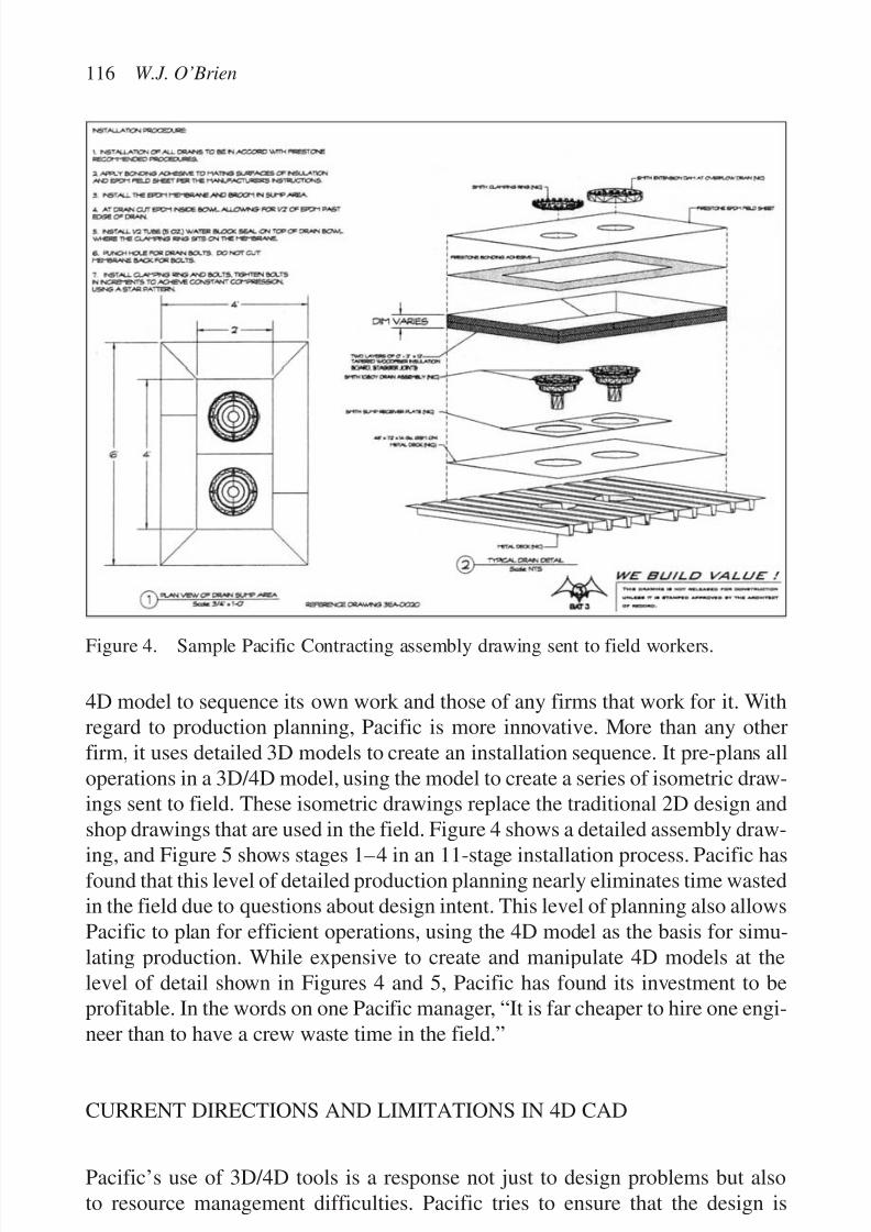
7/14/2019 4DCAD and Visualization in Construction
http://slidepdf.com/reader/full/4dcad-and-visualization-in-construction-56327c6a084e9 125/296
4D model to sequence its own work and those of any firms that work for it. Withregard to production planning, Pacific is more innovative. More than any otherfirm, it uses detailed 3D models to create an installation sequence. It pre-plans alloperations in a 3D/4D model, using the model to create a series of isometric draw-ings sent to field. These isometric drawings replace the traditional 2D design andshop drawings that are used in the field. Figure 4 shows a detailed assembly draw-
ing, and Figure 5 shows stages 1–4 in an 11-stage installation process. Pacific hasfound that this level of detailed production planning nearly eliminates time wastedin the field due to questions about design intent. This level of planning also allowsPacific to plan for efficient operations, using the 4D model as the basis for simu-lating production. While expensive to create and manipulate 4D models at thelevel of detail shown in Figures 4 and 5, Pacific has found its investment to beprofitable. In the words on one Pacific manager, “It is far cheaper to hire one engi-neer than to have a crew waste time in the field.”
CURRENT DIRECTIONS AND LIMITATIONS IN 4D CAD
Pacific’s use of 3D/4D tools is a response not just to design problems but alsoto resource management difficulties. Pacific tries to ensure that the design is
116 W.J. O’Brien
Figure 4. Sample Pacific Contracting assembly drawing sent to field workers.

7/14/2019 4DCAD and Visualization in Construction
http://slidepdf.com/reader/full/4dcad-and-visualization-in-construction-56327c6a084e9 126/296
complete, is coordinated with other disciplines, and is buildable. To optimize use of its resources and in conjunction with its “Last Planner” inspired resource assign-ment process, Pacific sequences its field production through the use of detailed
isometric drawings and also uses 3D models to create a detailed bill-of-materials.This use of 4D and production shielding is an effective way to optimize opera-tions on individual projects and to shield these operations from disruptions, andhas been very profitable for Pacific. However, despite the success of Pacific’sapproach, it does have limitations in that it stems from a single project perspective:all shielding and 4D planning occurs for individual projects and there is noexplicit framework to consider resource management and production planningfrom multi-project perspective. This is particularly troublesome under conditions
of uncertainty, something that Pacific is subject to even with its planning. Thusthere is a need to extend 4D techniques to a multi-project perspective.Before considering multi-project resource planning and costing extensions to
4D CAD, it is worthwhile to review the development and current state-of-the-artof 4D tools (beyond that practiced by Pacific). Current research directions in 4DCAD are logical descendants of earlier project centric research and practice with3D CAD models. The development of 3D CAD models in the late 1980s was a
4D CAD and dynamic resource planning for subcontractors 117
Figure 5. Sample Pacific Contracting installation stages drawing sent to field workers.

7/14/2019 4DCAD and Visualization in Construction
http://slidepdf.com/reader/full/4dcad-and-visualization-in-construction-56327c6a084e9 127/296
significant advance in the development of construction modeling technology. Theability to construct a virtual prototype before field construction began dramati-cally decreased interference among major systems (e.g. piping, mechanical, and
structural systems) and increased the speed and quality of design review. Otherearly uses of 3D CAD models included limited studies in constructability. On oneproject, 3D CAD models and renderings were used in coordination meetings todiscuss trade sequencing (Griffis et al., 1990). Research activities associated withthat project explored the link between traditional simulation of construction activ-ities and simulation of construction in the context of the 3D model (Griffis et al.,1991). This work quickly led to the development of 4D CAD approaches to mod-eling both the facility and the construction process. Early 4D CAD efforts manuallyintegrated schedule information with 3D models to represent the planned state of facility construction at fixed points in time. Later 4D CAD research efforts automatedthe link between scheduling software and 3D models to create more flexible anddynamic 4D representations of construction progress. Research has also focusedon generation of automated (4D) schedules by reasoning about the 3D design andconstruction process information (e.g. Darwiche et al., 1988; Thabet & Beliveau,1994, 1997). Current application and research frontiers in 4D CAD include detailedwork planning (Riley, 2000) and coordination of multiple trades in a dynamic anduncertain project environment (Akinci & Fischer, 1998; Tommelein, 2000).
Research has also begun to incorporate construction costs in 4D CAD models.Staub-French & Fischer (1999) review the practical needs of cost, schedule andscope integration and outline an approach to cost planning at the activity and objectlevel in a 4D environment. Staub-French & Fischer’s (1999) research perspectivecan be shown in Figure 6, where cost is a third link in a triangle integrating cost,
118 W.J. O’Brien
Figure 6. Current state of 4D CAD research—linking design, schedule, and cost in thecontext of a single project.

7/14/2019 4DCAD and Visualization in Construction
http://slidepdf.com/reader/full/4dcad-and-visualization-in-construction-56327c6a084e9 128/296
scope (design), and schedule in the context of a single project. They identify sev-eral impediments to effective integration of project information, in particular dif-ferent levels of aggregation in the use and generation of design, schedule, and cost
data. Through case examples, Staub-French and Fischer also show how the stan-dard construction accounting and control methods and existing software are oftentoo rigid to accommodate dynamic reasoning about and representation of con-struction methods. Building on the work of Fischer & Aalami (1996), they proposea conceptual schema that will accommodate both different uses and different levelsof aggregation of construction information in a unified format that will allow inte-gration of cost, schedule, and scope on a project.
While creating increasingly more powerful tools, research in 3D/4D CAD hasstemmed from a single project perspective. Existing 3D/4D tools do not directlysupport a multi-project viewpoint (a perspective this author has called “5D CAD”in to distinguish it from single project approaches (O’Brien, 2000b)). Based on thediscussion above, a multi-project or 5D CAD tool should support decisions aboutcost, time, and resources at the firm level. While more research needs to be per-formed developing integrated costing models to provide a decision support frame-work for multi-project resource management, several extensions to 4D techniquesare possible. Let us consider them in the context of the resource managementquestions presented above. Consider the first three questions:
• Which project should we borrow resources from?
• Which project should we deploy idle resources to?
• What are the ripple effects of a resource re-allocation and what do they cost?
These are intimately related and concern the daily operational decisions a sub-contractor must make about where and how to deploy resources. Should there bea problem or acceleration on one project, the first question asks which of the sub-contractor’s other projects should resources be borrowed from. This is not a sim-
ple question as moving resources from one project to another may simply solveone crisis by creating another. Many subcontractors do shift resources, and manysubcontractors do seem to always be running late. Similarly, deploying idleresources to a project may not help that project. If the subcontractor completeswork early on one project, which project should it allocate those now idleresources to? Ideally, the subcontractor will maintain a level use of resources (per-haps with some spare capacity from a queuing perspective (Hopp & Spearman,2000)), and should there be changes, the subcontractor will seek to minimize the
cost or consequences of any ripple effects.Thus, for the first three questions, what is needed is an extension of 4D CADthat allows the ripple effects of resource re-allocations to be modeled. This can beaccomplished manually today insofar as we can assess productivity on a projectfor a given resource level. With some knowledge of the overall schedule for eachproject (especially with regard to float and space) and any penalties for delays(and incentives for early completion), it is possible to model the impact of a given
4D CAD and dynamic resource planning for subcontractors 119

7/14/2019 4DCAD and Visualization in Construction
http://slidepdf.com/reader/full/4dcad-and-visualization-in-construction-56327c6a084e9 129/296
resource re-allocation on each project. The overall impact of any proposed changecan thus be assessed by individually evaluating each affected project. Of course,this is extremely cumbersome to do manually, and should a resource re-allocation
generate significant further re-allocations (i.e. large ripples) it may be impossibleto manually enumerate all the possibilities. What is needed is a 4D tool thatallows automatic exploration of the impact of resource re-allocations on a project.With this, we also need a tool that tracks the impact across projects (includingripple effects), allowing exploration and evaluation of changes. This appears to bea significant research challenge, although some groundwork has been put inplace by the automatic space and conflict evaluation work of Akinci & Fischer(1998) and Thabet & Beliveau (1997), and the resource tracking work of Chooet al. (1999).
The second set of questions concern themselves more with planning than withoperations:
• How do we value the flexibility of resource deployment on a project whenbidding?
• What is the most profitable mix of projects?
• How does production technology affect our ability to accommodate changes?
These questions are seemingly unrelated, but consider that a subcontractor’s
management knows there is a high probability of resource re-allocation. In thiscase, the management would like to have a set of projects where re-allocation of resources is not costly. Conceptually, one set of projects will be more or less flex-ible in accommodating changes than another set of projects. This flexibilitydirectly relates to profitability, and thus subcontractor management would liketo assess the value resource flexibility on projects both individually and as a set.To a certain extent, some subcontractors already practice choice about projectmix; e.g. one steel fabrication and erection subcontractor studied likes to work on
one large project and several small ones at any given time (O’Brien, 1998). Sucha mix provides the firm with flexibility in meeting changes while keeping near fulluse of its productive resources.
Valuing flexibility is not simple. Influences on the cost of shifting resourcesinclude not just schedules and any associated penalties, but also the technologiesinvolved. In a simple sense, a subcontractor cannot shift from one technology toanother if there are different equipment and skills involved. In a broader sense,construction technologies can accommodate changes in resource level with differ-
ent levels of impact on productivity (see O’Brien, 1998, 2000a for more discussionand examples). With knowledge of the impact of a technology on productivity,conceptually it is possible to extend the 4D/ripple-effect technologies envisionedabove to provide detailed knowledge about the value of flexibility for a given setof projects. Essentially, the question is the same: what is the impact of a change?Of course, in the early planning stages less detail will be known about the proj-ect(s) than in the operational stages. It is unclear if the same set of technologies
120 W.J. O’Brien
7/14/2019 4DCAD and Visualization in Construction
http://slidepdf.com/reader/full/4dcad-and-visualization-in-construction-56327c6a084e9 130/296
that will allow detailed assessment and enumeration of changes for improvementin operations will work in a less information rich environment. It is likely thatthe data from the 4D technologies envisioned would have to be put into some sort
of options framework (Trigeorgis, 1996; Brennan & Trigeorgis, 2000) that canaccommodate uncertainty.The final questions directly concern short-term operational planning rather than
accommodation of changes after they occur (questions 1–3) or with pre-bid orinvestment planning (questions 4–6):
• How should we negotiate a schedule with a contractor?
• How much reserve capacity should we have to accommodate changes?
If the first three questions (above) concern themselves of what to do after a changeoccurs, these final questions concern themselves with planning for those changes.With some knowledge of the value of a mix of projects and the influence of sched-ules and incentives on that value, subcontractors can better address the detailednegotiations with contractors about cost/price, schedule, materials, etc. Similarly,with a solid plan of projected resource assignment to projects over time, subcon-tractors can better negotiated a detailed schedule of work area hand over dates onindividual projects. With regard to extensions to 4D tools, it is likely that a com-bination of the tools described above will provide subcontractors with the requi-
site knowledge about what to do. New development that is needed is a bettervisualization tool to support negotiations between the contractor and the subcon-tractor(s).
As for schedule changes, improved knowledge about the impact of possiblechanges on cost and schedule can guide the subcontractor in making choices aboutreserve capacity. Subcontractors can choose to keep some resources in reserve fora given mix of projects (type and amount of resources determined by the extended4D tools), or they can choose to make strategic investments in new resources (either
rental or new permanent investment). As with schedule negotiation, some combi-nation of the tools envisioned above will provide the necessary decision support.
CONCLUSIONS
Methods and models in 4D CAD have many benefits to construction projects, not
least an ability to resolve design and construction conflicts before they occur in thefield. Efforts in 4D CAD can be seen as a way to reduce the incidence of costlychanges on construction projects. However, even in a world with widespread use of 4D CAD, changes in schedule and scope will remain a salient feature of construc-tion projects. A core competency of subcontractors is the ability to adjust to thesechanges in a low cost manner. The principal difficulty that subcontractors have inadjusting to changes is maintaining a level use of their finite resources. Any change
4D CAD and dynamic resource planning for subcontractors 121
7/14/2019 4DCAD and Visualization in Construction
http://slidepdf.com/reader/full/4dcad-and-visualization-in-construction-56327c6a084e9 131/296
in schedule and scope on one project can cause changes in resource allocation toother projects. This creates a complex interaction between projects and costs thatcannot be captured in the single project perspective of 4D CAD models.
The questions above developed from the multi-project perspective of subcon-tractors are very different from the questions asked of single project 4D models. Amulti-project perspective does not invalidate current 4D research but does suggestaugmentation of and parallel development with 4D research efforts. A multi-project decision support model (“5D”) needs detailed information about individ-ual projects, in particular the likelihood of changes in schedule and scope anduncertainty in production progress, feasibility of alternative work plans, and theflexibility of a project in loaning or absorbing resources. The work of Riley (2000)in developing detailed work plans in a 4D environment, Akinci & Fischer (1998)in generating production alternatives in an integrated fashion, and Tommelein(2000) in understanding the affects of uncertainty on production are useful in amulti-project context. Similarly, Staub-French & Fischer’s (1999) schema for costintegration should provide a partial basis for reasoning about multi-project costs.Multi-project resource allocation models also provide information to improvedecision making in a single project context. That subcontractors can and do shiftresources among projects (O’Brien & Fischer, 2000) suggests that production rea-soning in 4D CAD models based on static models of resource allocation will give
inaccurate results. A multi-project model can improve the accuracy of projectschedules, and provide improved support for cost negotiations when there arechanges in schedule and scope. More broadly, the dynamic resource planningextensions to 4D CAD promise development of methods to plan projects from theperspective of subcontractor ability to respond to changes, allowing us to generateproject schedules that are efficient and flexible.
REFERENCES
Abu-Hijleh, S.F. & Ibbs, C.W. 1989. Schedule-based construction incentives. Journal of Construction Engineering and Management 115(3): 430–443. ASCE.
Akinci, B. & Fischer, M. 1998. Time–space conflict analysis based on 4D productionmodels. In K.C.P. Wang (ed.), International computing congress, Boston, 18–21October: 342–353. ASCE.
Antill, J.M. & Woodhead, R.W. 1990. Critical path methods in construction practice.New York: Wiley.
Ashley, D.B. & Workman, B.W. 1986. Incentives in construction contracts. Report 83-5,Construction Industry Institute.
Askin, R.G. & Standridge, C.R. 1993. Modeling and analysis of manufacturing systems.New York: John Wiley and Sons, Inc.
Ballard, G. & Howell, G. 1998. Shielding production: essential step in production control. Journal of Construction Engineering and Management 124(1): 11–17. ASCE.
Banker, R.D., Datar, S.M. & Kekre, S. 1988. Relevant costs, congestion and stochasticityin production environments. Journal of Accounting and Economics 10(3): 171–197.
122 W.J. O’Brien

7/14/2019 4DCAD and Visualization in Construction
http://slidepdf.com/reader/full/4dcad-and-visualization-in-construction-56327c6a084e9 132/296
Bennett, J. & Ferry, D. 1990. Specialist contractors: a review of issues raised by their newrole in building. Construction Management and Economics 8(3): 259–283.
Birrell, G.S. 1980. Construction planning—beyond the critical path. Journal of theConstruction Division 106(CO3): 389–407. ASCE.
Brennan, M.J. & Trigeorgis, L. 2000. Project flexibility, agency, and competition: newdevelopments in the theory and application of real options. New York: OxfordUniversity Press.
Choo, H.J. & Tommelein, I.D. 2000a. Interactive coordination of distributed work plans.In K.D. Walsh (ed.), Proceedings of construction congress VI: Building together for abetter tomorrow in an increasingly complex world, Orlando, Florida, 20–22 February:11–20. ASCE.
Choo, H.J. & Tommelein, I.D. 2000b. WorkMovePlan: database for distributed planningand coordination. In J. Barlow (ed.), Eighth annual conference of the IGLC , Universityof Sussex, Brighton, United Kingdom, 17–19 July: 12 pp.
Choo, H.J., Tommelein, I.D., Ballard, G. & Zabelle, T.R. 1999. WorkPlan: constraint-based database for work package scheduling. Journal of Construction Engineering and Management 125(3): 151–160. ASCE.
Darwiche, A., Levitt, R. & Hayes-Roth, B. 1988. OARPLAN: generating project plans byreasoning about objects, actions, and resources. AI EDAM 2(3): 169–181.
Fischer, M. & Aalami, F. 1996. Scheduling with computer-interpretable construction methodmodels. Journal of Construction Engineering and Management 122(4): 337–347. ASCE.
Fondahl, J.W. 1961. A non-computer approach to the critical path method for theconstruction industry. Technical Report 9, The Construction Institute, Department of
Civil Engineering, Stanford University.Gershwin, S.B. 1994. Manufacturing systems engineering, Englewood Cliffs, NJ:Prentice-Hall, Inc.
Gray, C. & Flanagan, R. 1989. The changing role of specialist and trade subcontractorsAscot: The Chartered Institute of Building.
Griffis, F.H. & Butler, F.M. 1988. Case for cost-plus contracting. Journal of Construction Engineering and Management 114(1): 83–94. ASCE
Griffis, F., O’Brien, W. & Bronner, P. 1990. Columbia construction research: theapplications of three-dimensional computer models in construction. Architectural and Engineering Systems.
Griffis, F.H., Rubinson, D., O’Brien, W., Retailleau, S. & Zabilsky, R. 1991. Productivityapplications: 3D models and simulation. Proceedings of construction congress ’91:247–252. ASCE.
Gross, D. & Harris, C.M. 1985. Fundamentals of queueing theory. New York: John Wiley& Sons, Inc.
Hinze, J. & Tracey, A. 1994. The contractor–subcontractor relationship: the sub-contractor’s view. Journal of Construction Engineering and Management 120(2):274–287. ASCE.
Hopp, W.J. & Spearman, M.L. 2000. Factory physics. New York: McGraw-Hill.O’Brien, W.J. 1998. Capacity costing approaches for construction supply-chain
management . Ph.D. Dissertation, Stanford University.O’Brien, W.J. 2000a. Multi-project resource allocation: parametric models and
managerial implications. In J. Barlow (ed.), Eighth annual conference of the IGLC.University of Sussex, Brighton, United Kingdom, 17–19 July: 11 pp.
O’Brien, W.J. 2000b. Towards 5D CAD—dynamic cost and resource planning forspecialist contractors. In K.D. Barlow (ed.), Proceedings of construction congress VI: Building together for a better tomorrow in an increasingly complex world, Orlando,Florida, 20–22 February, 2000: 1023–1028. ASCE.
4D CAD and dynamic resource planning for subcontractors 123

7/14/2019 4DCAD and Visualization in Construction
http://slidepdf.com/reader/full/4dcad-and-visualization-in-construction-56327c6a084e9 133/296
O’Brien, W.J. & Fischer, M.A. 2000. Importance of capacity constraints to constructioncost and schedule. ASCE Journal of Construction Engineering and Management 125(6): 366–373.
O’Brien, W.J., Fischer, M.A. & Jucker, J.V. 1995. An economic view of project
coordination. Construction Management and Economics 13(5): 393–400.Pinedo, M. 1995. Scheduling: theory, algorithms, and systems. Englewood Cliffs, NJ:
Prentice Hall.Riley, D. 2000. The role of four-dimensional (4D) models in trade sequencing and
production planning. In K.D. Walsh (ed.), Proceedings of construction congress VI: Building together for a better tomorrow in an increasingly complex world , Orlando,Florida: 20–22, February, 2000: 1029–1034. ASCE.
Staub-French, S. & Fischer, M. 1999. The practical needs of integrating scope, cost, andtime. Proceedings of the 8th international conference on durability of buildingmaterials and component, May 30–June 3, 1998: 2888–2898. Vancouver, Canada:NRC Research Press.
Stukhart, G. 1984. Contractual incentives. Journal of Construction Engineering and Management 110(1): 34– 42. ASCE.
Thabet, W.Y. & Beliveau, Y.J. 1994. Modeling work space to schedule repetitive floors inmultistory buildings. Journal of Construction Engineering and Management 120(1):96–116. ASCE.
Thabet, W.Y. & Beliveau, Y.J. 1997. SCaRC: Space-constrained resource-constrainedscheduling system. Journal of Computing in Civil Engineering 11(1): 48–59. ASCE.
Tommelein, I. 2000. Impact of variability and uncertainty on integrated product and
process development. In K. Walsh (ed.), Proceedings of construction congress 6,special program of 4D CAD and visualization, Orlando, Florida, 20–22 February,2000: 969–976 . ASCE.
Trigeorgis, L. 1996. Real options: managerial flexibility and strategy in resourceallocation. Cambridge, Massachusetts: The MIT Press.
Uher, T.E. 1991. Risks in subcontracting: subcontract conditions. Construction Management and Economics 9(3): 495–508.
124 W.J. O’Brien

7/14/2019 4DCAD and Visualization in Construction
http://slidepdf.com/reader/full/4dcad-and-visualization-in-construction-56327c6a084e9 134/296
THE ROLE OF 4D MODELING IN TRADE SEQUENCINGAND PRODUCTION PLANNING
David Riley
Department of Architectural Engineering, Penn State University,
University Park, PA, USA
125
Abstract
A new class of planning tools has been developed through advancements in CAD and
Scheduling software integration. 4D modeling provides a mechanism to visualize ele-
ments of 3D CAD models based on associated schedule intervals. This technology allows
project managers to evaluate construction plans for time and space conflicts between oper-ations and building elements. The use of 4D modeling for planning project logistics and
evaluating project schedules is evolving rapidly. Recent research explores the 4D modeling
of work spaces and material movement. Planning such spaces can be highly challenging
when multiple sequence options and complex networks of prerequisite work exist. This
paper discusses the use of 4D modeling for detailed trade sequencing and production plan-
ning for construction. Case studies of the sequence planning process are used to demon-
strate how visualization and “what-if” tools could be used to improve the planning process.
Conceptual methodologies are presented for modeling construction work spaces to support
production planning, e.g. work, storage, and paths which are necessary to perform usefulmodeling and simulation of a dynamic work environment. The goal of this research is to
identify appropriate applications for 4D modeling in the sequence planning process, and
to make recommendations for the development of future 4D planning tools.
Keywords: 4D CAD, CAD, coordination, planning, visualization
INTRODUCTION
The integration of time with 3D spatial data permits the simulation of the dynamicwork environments found on construction projects. 4D modeling provides a mecha-nism to simulate building elements and work spaces in a manner much more appro-priate than traditional static layout plans and schedules. The benefits of 4D modeling
7/14/2019 4DCAD and Visualization in Construction
http://slidepdf.com/reader/full/4dcad-and-visualization-in-construction-56327c6a084e9 135/296
have been demonstrated through experimentation, and include the identificationof potential conflicts between building elements and work spaces, safety hazardscreated due to proximity of construction activities, and the visualization of construc-
tion plans by crews (McKinney & Fischer, 1998). This paper is divided into twosections: Part One, which focuses on the planning process and potential benefitsof 4D modeling to production planning; and Part Two, which focuses on model-ing issues and the implementation challenges of 4D modeling for production plan-ning. As a guide to the reader, each part is briefly introduced.
Part One of this paper discusses the implementation of 4D modeling in an envi-ronment that typically resists large investments in detailed planning, and the poten-tial impacts of 4D modeling on the creation of work sequences and production plansin construction. Consideration is given to the pragmatic issues facing constructionplanners such as the perceived lack of time for detailed planning. In an effort toaddress these issues, existing planning processes are examined to identify the mostlikely project attributes that lend themselves to useful applications of 4D modeling.
Part Two of this paper explores the detailed modeling issues needed for theinclusion of physical work spaces, storage areas, and material paths as 3D objectsin a 4D analysis of a construction project. Using experience from case studies andspace planning efforts (described in more detail in Riley & Sanvido, 1995), attri-butes and properties for the modeling of construction spaces are defined. Next, the
primary inputs and outputs of the planning process are discussed to demonstratethe role of these properties in the 4D planning environment. Finally, the relation-ships between the planning environment and the level of detail at which 4D mod-eling should be performed are discussed.
PART ONE—4D MODELING FEASIBILITY
3D computer models are rarely produced for building construction projects. Manycontractors are quick to assume that the cost of CAD operators makes this type of investment too costly. On projects with complex geometric configurations of sys-tems, however, 3D models are the most effective tool for examining the designof building elements. Examples of such spaces are mechanical rooms, interstitialspaces, and ceiling plenums. Many contractors recognize the value of 3D modelsin such areas, and invest in CAD operators for this purpose. 4D models provide an
added dimension to planning, and permit the impact of work in place and availablework space to be evaluated in addition to conflicts between building components.As building owners continuously demand more aggressive building schedulesand computer modeling tools continue to become more affordable and easy to use,the development of 3D and 4D models will become more feasible. This paperexplores the integration of 4D modeling into existing planning practices to helpidentify its most practical and feasible applications in construction.
126 D. Riley

7/14/2019 4DCAD and Visualization in Construction
http://slidepdf.com/reader/full/4dcad-and-visualization-in-construction-56327c6a084e9 136/296
4D MODELING AND DESIGN COORDINATION
A 4D model is typically created by associating schedule data with the elementsof a 3D model. Since the most common use of a 3D model is for design coordina-tion, it is logical that 4D models are likely most feasible on projects that alsorequire extensive coordination between technical building systems and construc-tion operations. In recent years the process of coordinating the design of mechan-ical, electrical, and plumbing (MEP) systems has intensified. Building systemsare more complex and specialized, and the role of specialty contractors in thedesign process has increased. As a result, many contractors have recognized that alarge investment in coordination, usually with CAD tools, is necessary to avoid
costly delays due to conflicts. This coordination process offers the most likelyopportunity to effectively generate and benefit from 4D models.
4D MODELING AND THE PRODUCTION PLANNING PROCESS
A major challenge to construction managers is the conceptualization of how work
crews, equipment, and materials will compete for limited available space duringa construction project. 4D modeling provides a tool to visualize available spaceduring the course of a construction project. Successful planning practices wereinvestigated by Riley (1994) to determine how the management of space was usedto create productive work environments. The results of this study are used to providea framework for the integration of 4D modeling into the production planningprocess. The following five requirements of plans were identified:
Provide spatial information: The decisions about how to use spaces on the siteare made almost every day. A 4D model should provide spatial information to answerthe following key questions:
• How should an activity be sequenced so that it does not interfere with the work of other activities or block paths?
• Where is space available for a given amount of time for work, material or pathrelated use?
• When can materials be brought to the job without interfering with the work of activities, needing to be relocated (double handled), or having to be moved longdistances between material and storage spaces?
Balance project needs: 4D planning should consider three interdependent fac-tors: productivity, quality, and safety. It should address all trades concurrently withan overall productive work environment as its primary objective.
4D modeling in trade sequencing and production planning 127
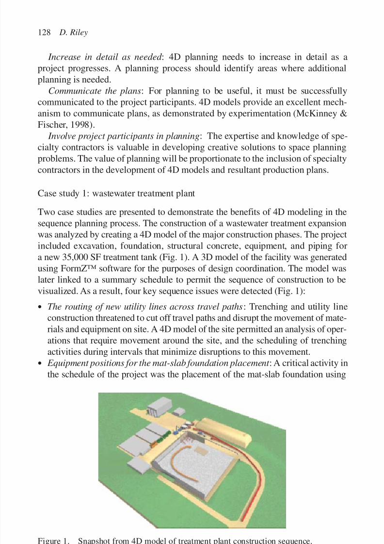
7/14/2019 4DCAD and Visualization in Construction
http://slidepdf.com/reader/full/4dcad-and-visualization-in-construction-56327c6a084e9 137/296
Increase in detail as needed : 4D planning needs to increase in detail as aproject progresses. A planning process should identify areas where additionalplanning is needed.
Communicate the plans: For planning to be useful, it must be successfullycommunicated to the project participants. 4D models provide an excellent mech-anism to communicate plans, as demonstrated by experimentation (McKinney &Fischer, 1998).
Involve project participants in planning: The expertise and knowledge of spe-cialty contractors is valuable in developing creative solutions to space planningproblems. The value of planning will be proportionate to the inclusion of specialtycontractors in the development of 4D models and resultant production plans.
Case study 1: wastewater treatment plant
Two case studies are presented to demonstrate the benefits of 4D modeling in thesequence planning process. The construction of a wastewater treatment expansionwas analyzed by creating a 4D model of the major construction phases. The projectincluded excavation, foundation, structural concrete, equipment, and piping fora new 35,000 SF treatment tank (Fig. 1). A 3D model of the facility was generatedusing FormZ™ software for the purposes of design coordination. The model was
later linked to a summary schedule to permit the sequence of construction to bevisualized. As a result, four key sequence issues were detected (Fig. 1):
• The routing of new utility lines across travel paths: Trenching and utility lineconstruction threatened to cut off travel paths and disrupt the movement of mate-rials and equipment on site. A 4D model of the site permitted an analysis of oper-ations that require movement around the site, and the scheduling of trenchingactivities during intervals that minimize disruptions to this movement.
• Equipment positions for the mat-slab foundation placement : A critical activity in
the schedule of the project was the placement of the mat-slab foundation using
128 D. Riley
Figure 1. Snapshot from 4D model of treatment plant construction sequence.
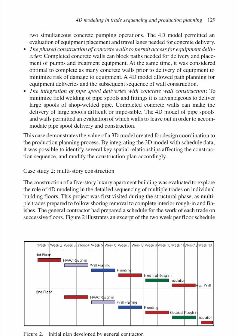
7/14/2019 4DCAD and Visualization in Construction
http://slidepdf.com/reader/full/4dcad-and-visualization-in-construction-56327c6a084e9 138/296
two simultaneous concrete pumping operations. The 4D model permitted anevaluation of equipment placement and travel lanes needed for concrete delivery.
• The phased construction of concrete walls to permit access for equipment deliv-
eries: Completed concrete walls can block paths needed for delivery and place-ment of pumps and treatment equipment. At the same time, it was consideredoptimal to complete as many concrete walls prior to delivery of equipment tominimize risk of damage to equipment. A 4D model allowed path planning forequipment deliveries and the subsequent sequence of wall construction.
• The integration of pipe spool deliveries with concrete wall construction: Tominimize field welding of pipe spools and fittings it is advantageous to deliverlarge spools of shop-welded pipe. Completed concrete walls can make thedelivery of large spools difficult or impossible. The 4D model of pipe spoolsand walls permitted an evaluation of which walls to leave out in order to accom-modate pipe spool delivery and construction.
This case demonstrates the value of a 3D model created for design coordination tothe production planning process. By integrating the 3D model with schedule data,it was possible to identify several key spatial relationships affecting the construc-tion sequence, and modify the construction plan accordingly.
Case study 2: multi-story constructionThe construction of a five-story luxury apartment building was evaluated to explorethe role of 4D modeling in the detailed sequencing of multiple trades on individualbuilding floors. This project was first visited during the structural phase, as multi-ple trades prepared to follow shoring removal to complete interior rough-in and fin-ishes. The general contractor had prepared a schedule for the work of each trade onsuccessive floors. Figure 2 illustrates an excerpt of the two week per floor schedule
4D modeling in trade sequencing and production planning 129
Figure 2. Initial plan developed by general contractor.
7/14/2019 4DCAD and Visualization in Construction
http://slidepdf.com/reader/full/4dcad-and-visualization-in-construction-56327c6a084e9 139/296
for each trade. This schedule allowed for only one trade on a floor at a time, anddemanded the completion of one floor every two weeks. No plan for a specificwork direction was identified for the floors, as trades were expected to follow the
removal of concrete shoring to begin their work sequence on each floor.Several problems existed with the initial plan. The MEP contractors on thisproject believed they would not be capable of completing the large floor plate intwo weeks with their available workforce. Also, the lack of a defined work direc-tion meant that crews of different trades would be forced to establish work sequence amongst themselves. Finally, no defined plan for loading materials ontothe “L”-shaped floor plate had been established, allowing for walls and work inplace to potentially obstruct material delivery and movement.
Using a 2D CAD drawing of the floor plate and assigning a workflow throughdefined work spaces, the plan was evaluated more closely. By graphically review-ing the work on each floor in stages, it was determined that a phased constructionof walls would permit open travel lanes for material handling activities necessaryafter the original scheduled wall construction. Also, by assigning a work directionon each floor, it was possible to manage how crews moved through each floor.This permitted multiple trades to occupy a single floor and remain out of eachother’s way, and at the same time allow each trade to have more time on each floor.Figures 3 and 4 illustrate the proposed sequence of trades across a representative
floor, and the associated work spaces needed for each trade.In addition to the revised sequence of wall construction, the major change to the
original plan essentially reduces the “batch size” of work for each trade from theentire floor plate, to one wing of each floor. The characterization of constructionwork activities in terms of available space permits quantities of repetitious work to be grouped into desirable “batches” and adds detail to a work plan that goesbeyond activities in the CPM schedule. The relationships between sequence, batchsize, and buffers to 4D modeling methodologies will be discussed in more detail
in Part Two of this paper.Figure 5 illustrates the revised plan. The new schedule is no longer sequential,
as now multiple trades are planned to occupy the same floor at the same time. Thedurations of the MEP activities, however are extended and thus more realistic. Asthe plan was implemented, it was modified slightly to accommodate the shoringremoval, however the trades were able to complete their work with minimal inter-ference problems.
This case provides a classic example of the threshold of current planning and
visualization. The contractor was unwilling to schedule more than one trade onany given floor at a time, however had not accounted for the fact that several tradesdid not have the capacity to complete each floor at the stipulated rate. An exami-nation of the flow patterns of specific crews across building floors was needed. Byintegrating flow patterns and the phased construction of core and demising wallsinto a dynamic model of the construction process, it was possible to generate amore feasible production plan. While the duration of the overall floor construction
130 D. Riley
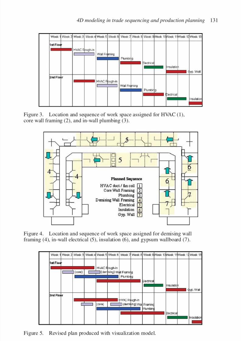
7/14/2019 4DCAD and Visualization in Construction
http://slidepdf.com/reader/full/4dcad-and-visualization-in-construction-56327c6a084e9 140/296
4D modeling in trade sequencing and production planning 131
Figure 3. Location and sequence of work space assigned for HVAC (1),core wall framing (2), and in-wall plumbing (3).
Figure 4. Location and sequence of work space assigned for demising wallframing (4), in-wall electrical (5), insulation (6), and gypsum wallboard (7).
Figure 5. Revised plan produced with visualization model.
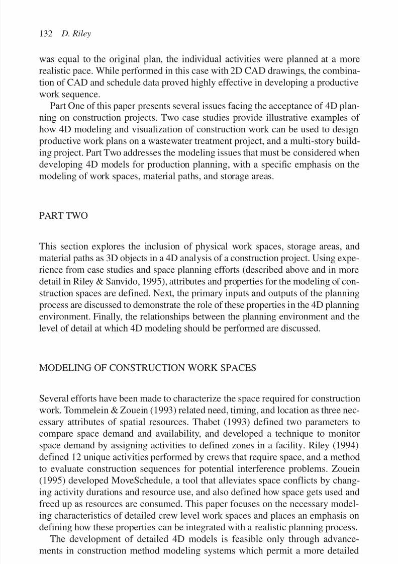
7/14/2019 4DCAD and Visualization in Construction
http://slidepdf.com/reader/full/4dcad-and-visualization-in-construction-56327c6a084e9 141/296
was equal to the original plan, the individual activities were planned at a morerealistic pace. While performed in this case with 2D CAD drawings, the combina-tion of CAD and schedule data proved highly effective in developing a productive
work sequence.Part One of this paper presents several issues facing the acceptance of 4D plan-ning on construction projects. Two case studies provide illustrative examples of how 4D modeling and visualization of construction work can be used to designproductive work plans on a wastewater treatment project, and a multi-story build-ing project. Part Two addresses the modeling issues that must be considered whendeveloping 4D models for production planning, with a specific emphasis on themodeling of work spaces, material paths, and storage areas.
PART TWO
This section explores the inclusion of physical work spaces, storage areas, andmaterial paths as 3D objects in a 4D analysis of a construction project. Using expe-rience from case studies and space planning efforts (described above and in moredetail in Riley & Sanvido, 1995), attributes and properties for the modeling of con-
struction spaces are defined. Next, the primary inputs and outputs of the planningprocess are discussed to demonstrate the role of these properties in the 4D planningenvironment. Finally, the relationships between the planning environment and thelevel of detail at which 4D modeling should be performed are discussed.
MODELING OF CONSTRUCTION WORK SPACES
Several efforts have been made to characterize the space required for constructionwork. Tommelein & Zouein (1993) related need, timing, and location as three nec-essary attributes of spatial resources. Thabet (1993) defined two parameters tocompare space demand and availability, and developed a technique to monitorspace demand by assigning activities to defined zones in a facility. Riley (1994)defined 12 unique activities performed by crews that require space, and a methodto evaluate construction sequences for potential interference problems. Zouein
(1995) developed MoveSchedule, a tool that alleviates space conflicts by chang-ing activity durations and resource use, and also defined how space gets used andfreed up as resources are consumed. This paper focuses on the necessary model-ing characteristics of detailed crew level work spaces and places an emphasis ondefining how these properties can be integrated with a realistic planning process.
The development of detailed 4D models is feasible only through advance-ments in construction method modeling systems which permit a more detailed
132 D. Riley

7/14/2019 4DCAD and Visualization in Construction
http://slidepdf.com/reader/full/4dcad-and-visualization-in-construction-56327c6a084e9 142/296
representation of how crews perform work than traditional CPM constructionschedules. Aalami et al. (1997) demonstrate the advantages of detailed methodmodeling with the Construction Method Modeler (CMM), and how this technique
permits the automated generation of detailed models of construction work sequences. This paper discusses issues related to the extension of the CMM toinclude models of construction work spaces at an equal level of detail, andassumes a planning technique will require a 3D model to be evaluated for conflictsat selected intervals. Adjustments could then be made to construction sequences orpositions of stored materials and paths.
ATTRIBUTES OF CONSTRUCTION WORK SPACES
The first step in defining attributes of construction work spaces is the definition of a modeling format and language to reference the different types of work spacesand their respective properties. Four key space needs by crews are physical work space, storage areas for materials, paths for material movement, and access pointsfor unloading materials onto building floors. These four spaces will be the focusof this discussion, as they are most intensely related to production planning of
multiple crews. The detailed modeling of discrete spaces, such as hazard areas,will be addressed later in a discussion of the types of potential conflicts that mayexist between work spaces.
Figure 6 illustrates an example of the spaces required to install two overheadfixtures. Each fixture requires a work space and a storage area at some nearbylocation. An access point and clear unloading space will also be needed.Connecting these spaces are paths between unloading and storage areas, andbetween storage areas and work areas. Paths between work spaces may also be
required. For simplicity in this example, it is assumed that all work spaces will berectilinear in shape.
Property definitions
Three categories of properties are used to describe construction work spaces as 4Dobjects: physical properties, which describes size, location, and density of work spaces; temporal properties, which associate the spaces to schedule data; andinherited , which associates spaces with product model objects and schedule activ-
ities. Table 1 provides a decomposition of these properties and more specific def-initions for each.Properties of 4D construction space objects vary between different types of
space usage. The number and types of spaces modeled may vary depending on thelevel of detail desired in the planning process, as will be discussed later. Initiallyhowever, it can be assumed that work spaces would be included in the 4D planningprocess. Certain material intensive properties may warrant storage spaces to be
4D modeling in trade sequencing and production planning 133
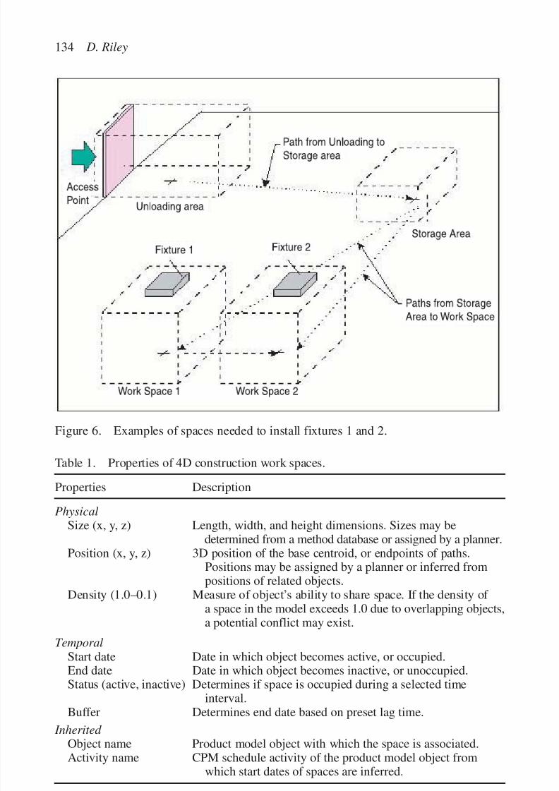
7/14/2019 4DCAD and Visualization in Construction
http://slidepdf.com/reader/full/4dcad-and-visualization-in-construction-56327c6a084e9 143/296
134 D. Riley
Figure 6. Examples of spaces needed to install fixtures 1 and 2.
Table 1. Properties of 4D construction work spaces.
Properties Description
PhysicalSize (x, y, z) Length, width, and height dimensions. Sizes may be
determined from a method database or assigned by a planner.Position (x, y, z) 3D position of the base centroid, or endpoints of paths.Positions may be assigned by a planner or inferred frompositions of related objects.
Density (1.0–0.1) Measure of object’s ability to share space. If the density of a space in the model exceeds 1.0 due to overlapping objects,a potential conflict may exist.
TemporalStart date Date in which object becomes active, or occupied.End date Date in which object becomes inactive, or unoccupied.
Status (active, inactive) Determines if space is occupied during a selected timeinterval.
Buffer Determines end date based on preset lag time.
Inherited Object name Product model object with which the space is associated.Activity name CPM schedule activity of the product model object from
which start dates of spaces are inferred.
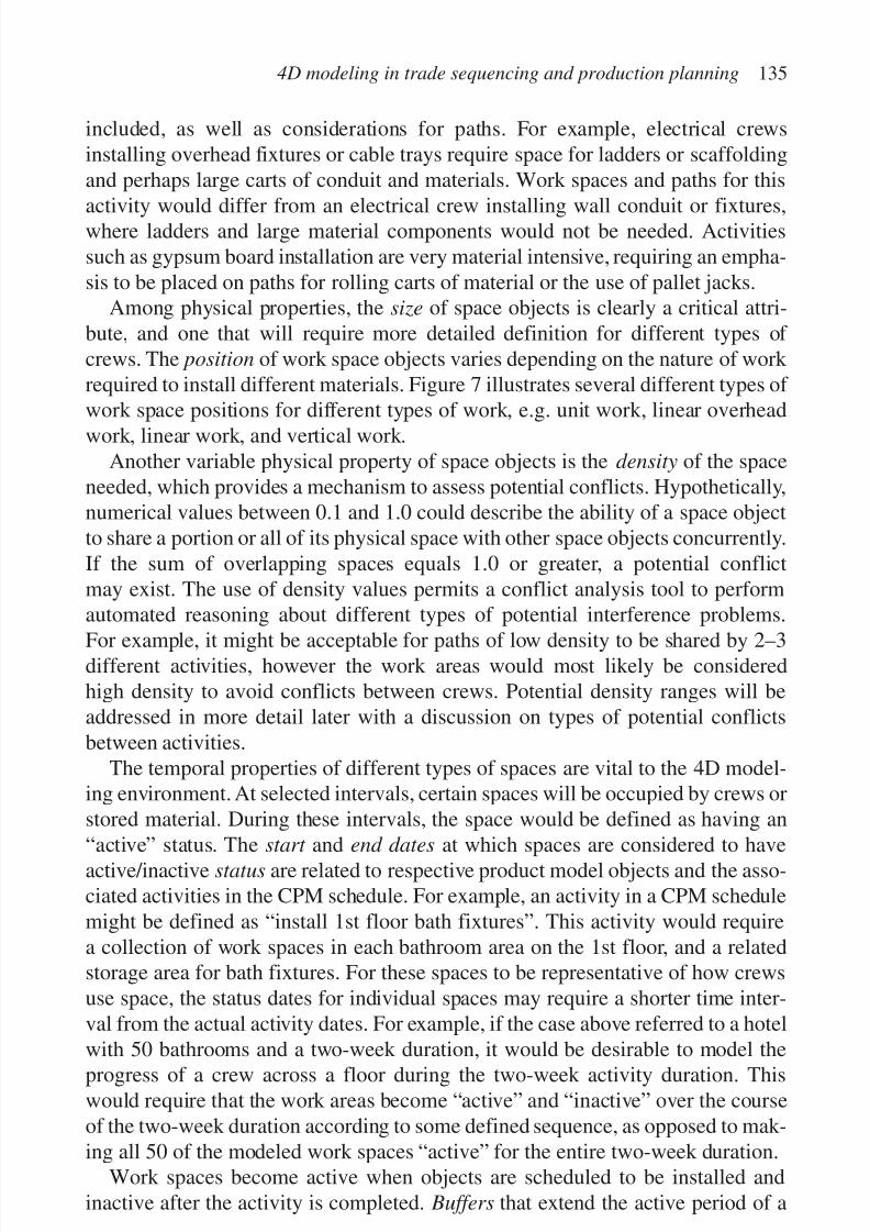
7/14/2019 4DCAD and Visualization in Construction
http://slidepdf.com/reader/full/4dcad-and-visualization-in-construction-56327c6a084e9 144/296
included, as well as considerations for paths. For example, electrical crewsinstalling overhead fixtures or cable trays require space for ladders or scaffoldingand perhaps large carts of conduit and materials. Work spaces and paths for this
activity would differ from an electrical crew installing wall conduit or fixtures,where ladders and large material components would not be needed. Activitiessuch as gypsum board installation are very material intensive, requiring an empha-sis to be placed on paths for rolling carts of material or the use of pallet jacks.
Among physical properties, the size of space objects is clearly a critical attri-bute, and one that will require more detailed definition for different types of crews. The position of work space objects varies depending on the nature of work required to install different materials. Figure 7 illustrates several different types of work space positions for different types of work, e.g. unit work, linear overheadwork, linear work, and vertical work.
Another variable physical property of space objects is the density of the spaceneeded, which provides a mechanism to assess potential conflicts. Hypothetically,numerical values between 0.1 and 1.0 could describe the ability of a space objectto share a portion or all of its physical space with other space objects concurrently.If the sum of overlapping spaces equals 1.0 or greater, a potential conflictmay exist. The use of density values permits a conflict analysis tool to performautomated reasoning about different types of potential interference problems.
For example, it might be acceptable for paths of low density to be shared by 2–3different activities, however the work areas would most likely be consideredhigh density to avoid conflicts between crews. Potential density ranges will beaddressed in more detail later with a discussion on types of potential conflictsbetween activities.
The temporal properties of different types of spaces are vital to the 4D model-ing environment. At selected intervals, certain spaces will be occupied by crews orstored material. During these intervals, the space would be defined as having an
“active” status. The start and end dates at which spaces are considered to haveactive/inactive status are related to respective product model objects and the asso-ciated activities in the CPM schedule. For example, an activity in a CPM schedulemight be defined as “install 1st floor bath fixtures”. This activity would requirea collection of work spaces in each bathroom area on the 1st floor, and a relatedstorage area for bath fixtures. For these spaces to be representative of how crewsuse space, the status dates for individual spaces may require a shorter time inter-val from the actual activity dates. For example, if the case above referred to a hotel
with 50 bathrooms and a two-week duration, it would be desirable to model theprogress of a crew across a floor during the two-week activity duration. Thiswould require that the work areas become “active” and “inactive” over the courseof the two-week duration according to some defined sequence, as opposed to mak-ing all 50 of the modeled work spaces “active” for the entire two-week duration.
Work spaces become active when objects are scheduled to be installed andinactive after the activity is completed. Buffers that extend the active period of a
4D modeling in trade sequencing and production planning 135
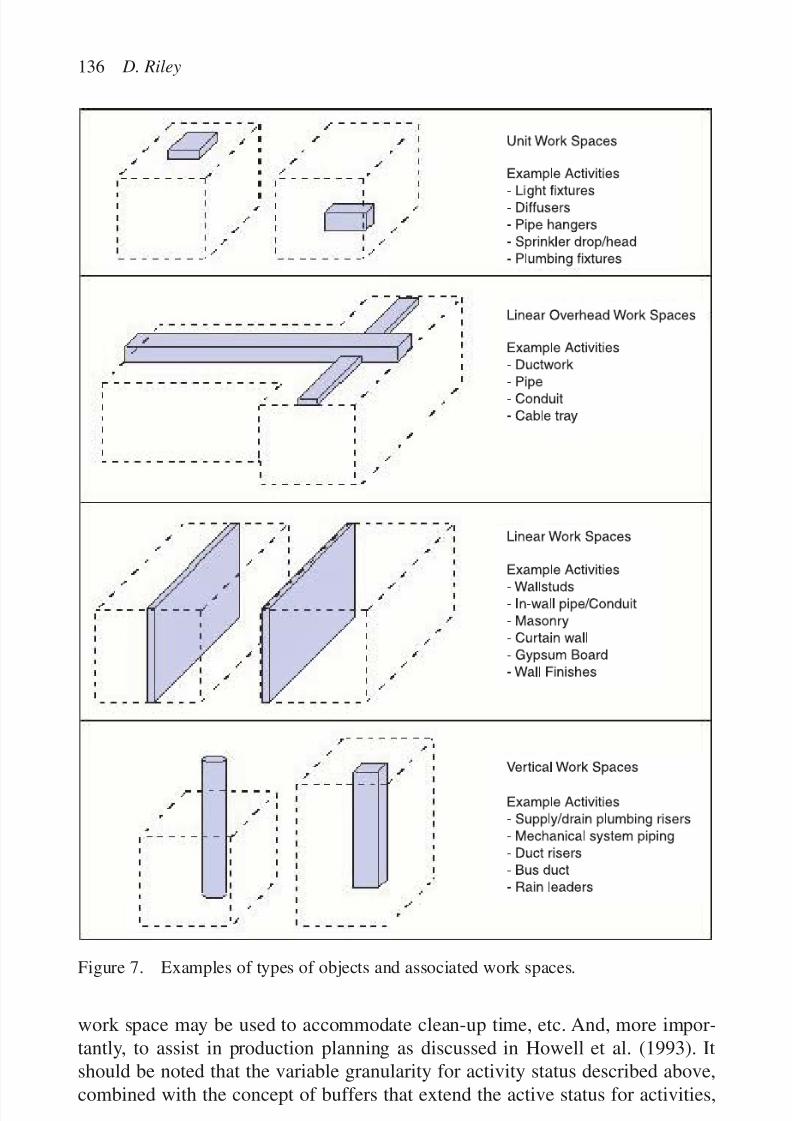
7/14/2019 4DCAD and Visualization in Construction
http://slidepdf.com/reader/full/4dcad-and-visualization-in-construction-56327c6a084e9 145/296
work space may be used to accommodate clean-up time, etc. And, more impor-tantly, to assist in production planning as discussed in Howell et al. (1993). Itshould be noted that the variable granularity for activity status described above,combined with the concept of buffers that extend the active status for activities,
136 D. Riley
Figure 7. Examples of types of objects and associated work spaces.
7/14/2019 4DCAD and Visualization in Construction
http://slidepdf.com/reader/full/4dcad-and-visualization-in-construction-56327c6a084e9 146/296
represent the two key variables needed for detailed production planning of multi-ple crews, which is the focus of this paper.
Recall the example in Part One of this paper, which discussed the multi-story
building project. In this case, the time interval of two weeks for an activity to takeplace on a building floor was insufficient to represent how crews actually movedacross the floor plate. By modeling individual work spaces that were “active” in adefined sequence, it was possible to demonstrate the feasibility of two or morecrews occupying a floor at the same time. This analysis made it possible to reducethe “batch size” of work that each crew performed before completed work areaswere made available to subsequent crews. It was also necessary, however, to allowcrews to proceed with a buffer of available work space between them to allow foruncertainty in the rate of progress for each crew. Tommelein et al. (1999) discussthe impact of uncertainty on the sequencing of multiple crews.
If spaces for material unloading, movement, and storage are included, activeand inactive times will take place at intervals surrounding respective object activ-ity start and end dates, and also require that material deliveries be included as sep-arate activities in the CPM schedule. For example, unloading areas and paths tostorage would only be active at times immediately prior to and during materialdelivery dates. Storage areas would be active from the dates materials are deliv-ered, until the respective activity is completed. Provisions may also be made for
these spaces to diminish in size over time as described by Zouein (1995). Inherited properties may include a multitude of attributes from product models
and schedules. At a minimum, however, the object name will indicate the productmodel object with which the space is associated, and the activity name willindicate the CPM schedule activity of the product model object from which startdates of spaces are inferred. This discussion presumes that a 4D model of thefacility is already completed, and thus permits work spaces to inherit propertiesfrom the associated building component and the schedule activity. The next sec-
tion will discuss in more detail the expected inputs and outputs to the planningprocess.
INPUTS AND OUTPUTS OF THE SPACE PLANNING PROCESS
For space planning to be effective, it must be viewed as an investment of planning
resources. For this investment to yield a return, it must be performed judiciously,on activities and projects which offer the opportunity to increase production withdetailed adjustment to batch size and work sequences. To minimize the invest-ment, the planning process should be efficient to perform and provide immediate,usable results. Existing space planning applications and construction projectswere investigated, Riley & Sanvido (1997), to determine a realistic set of inputsand outputs to a space planning process in a 4D environment.
4D modeling in trade sequencing and production planning 137
7/14/2019 4DCAD and Visualization in Construction
http://slidepdf.com/reader/full/4dcad-and-visualization-in-construction-56327c6a084e9 147/296
Inputs to planning
Space planning may be considered as a technique to evaluate scheduling orsequencing alternatives to determine if spatial conflicts exist between different
trades. Judgment must then be made as to the severity of potential spatial conflictsand potential course of action. For this reason, it is assumed that a 4D model of thefacility to be analyzed is a required input to the type of detailed planning describedin this paper. This 4D model consists of a 3D product model of the facility inwhich all objects to be planned are related to activities in a CPM constructionschedule.
Automated input: elements of 4D space planning that may be automated
• A 3D model of each work area to be considered in the planning process. Ideally,the development of a 3D product model should include the modeling of work spaces, in appropriate size, for each object in the model. An object oriented 3Dmodeling environment would permit these work spaces to be predefined for var-ious components of a building and generated concurrently with the 3D model.Figure 7 illustrates various work areas that could be associated with productmodel objects for unit work spaces in isolated locations (A), overhead sectionsof ductwork, pipe, or cable tray (B), linear wall assemblies, in-wall plumbing,
and electrical or wall finishes (C), or vertical sections of pipe risers, elevatorshafts, and ductwork, etc. (D).
• A property database for work spaces and associated spaces. The inherited proper-ties of construction work spaces described earlier must be included as attributesof work space objects in the model.
User input: elements of 4D space planning required by user
• A sequence in which model objects that are associated with unique constructionactivities become active would need to be determined by the planner. For exam-ple, a single schedule activity: “Install 4th floor light fixtures” requires furtherdetail to define the order in which fixtures are installed. Subsequent durationadjustments to schedule activities would then adjust the rate at which fixtureswould be installed and the rate at which a crew would move through the work spaces for that activity. It should also be noted that this sequence would mostlikely be changed to adjust work direction and flow rates.
• Assigned positions of material access points and storage areas for discrete ormultiple work areas. These positions are project specific, and cannot be inferredfrom the position of objects in the product model. From these locations the dis-tance and proximity relationships of material paths between access, storage, andwork spaces may also be calculated automatically. It would be advantageous todefine access points for material loading and waste removal, and allow pathsbetween these points and storage locations to be inferred by a planning tool.
138 D. Riley

7/14/2019 4DCAD and Visualization in Construction
http://slidepdf.com/reader/full/4dcad-and-visualization-in-construction-56327c6a084e9 148/296
• Lead times or fixed dates for material delivery to storage spaces which permitthe timing of material movement and required storage space to be calculatedfrom the CPM schedule information of respective objects in the product model.
For example, light fixtures may be loaded onto building floors two weeks priorto installation. Using lead times permits material loading dates to shift alongwith schedule changes, while fixed dates might be determined by manufactur-ing or logistical constraints on specialty materials.
Planning outputs
The ultimate product of 4D modeling and space planning should be a constructionplan that is free from disruptive spatial conflicts. The automated detection of potential conflicts between work space, storage areas, and paths of different crewsrepresents the primary goal of the 4D modeling process because it permits com-plex and long duration work sequences to be evaluated and re-evaluated afteradjustments are made.
Additional benefit would also be observed if automated reasoning about theseverity of potential conflicts were possible. For example, a planner may chooseto evaluate only specific types of conflicts or only those that occur for a planninginterval of one week or more. As discussed earlier when the concept of densitywas introduced as an attribute of 4D objects, it might be possible for particular
activity spaces to occupy the same location concurrently with little or no negativeimpact to production. Some materials may be stacked and some paths of low den-sity may be shared by more than one activity. Rules for evaluating the severity of detected spatial interferences based on their durations and density would also bebeneficial, and is the subject of current research.
Table 2 identifies six types of spatial conflicts that would be beneficial todetect, and a range of suggested densities that may be used to assess the severityof the conflict. A “full” density range indicates that the type of conflict should be
identified and resolved at all density levels of the spaces involved. A “variable”density range indicates that a conflict will only be identified between those typesof spaces if the sum of the densities of those spaces exceeds an unacceptablelevel.
4D modeling in trade sequencing and production planning 139
Table 2. Potential spatial conflicts between Activitya and Activityb.
Conflict type Represents conflict between Density range
(1) (2) (3)Work a–Work b Activitya and Activityb work spaces FullStoragea–Work b Activitya storage and Activityb work space FullPatha–Work b Activitya path and Activityb work space VariableStoragea–Storageb Activitya and Activityb storage areas VariablePatha–Pathb Activitya path and Activityb path VariablePatha–Storageb Activitya path and Activityb storage area Variable

7/14/2019 4DCAD and Visualization in Construction
http://slidepdf.com/reader/full/4dcad-and-visualization-in-construction-56327c6a084e9 149/296
Conflicts are identified only between spaces for different activities, e.g. storagespace of gypsum board and work space for sprinkler pipe. It is assumed that con-flicts between work, material, and paths for the same activities could be resolved
by the crew performing the work and should therefore be ignored during planning.This convention would also loosen the detail needed for modeling work spaces,and more likely permit the automatic generation of work spaces based on a 3Dproduct model.
The detail in modeling work spaces can be expanded to include more robustdescriptions of how space is used by activities, for example staging areas, hazardousareas, etc. Current research is focused on the use of 4D production models thatinclude more specialized representation of work spaces, thus permitting a vigorousanalysis of conflicts. Akinci & Fischer (1998) categorize such conflicts as thosecreating constructability problems, safety hazards, productivity problems, andpotential damage to work in place.
IMPACT OF PLANNING ENVIRONMENT ON MODELING DETAIL
Most planning efforts require a judgment to be made on the level of detail thatmust be included in the development of a realistic plan. When planning construc-tion sequences, too little detail may result in critical elements of a work sequencebeing overlooked, or in a lack of allowances for uncertainty. Conversely, too muchdetailed planning can become tedious and may exceed an appropriate level con-sidering inherent unexpected events and actions outside the control of manage-ment. Four aspects of 4D production models planning provide opportunities toadjust the level of detail in the planning process:
• Planning interval: A time frame that is planned and evaluated individually, e.g.hours, days, weeks.
• Space usage: Spaces that should be modeled, e.g. work, storage, prefabrica-tion, etc.
• Activity type: Crew level operations that warrant planning.
• Work zone: Specific areas of a facility that are likely candidates for congestion.
Planning interval
A precise model of the construction work environment is perhaps an unrealisticgoal since work crews typically plan at daily or hourly intervals. However, it isreasonable to assume that significant progress can be made in most crew leveloperations in a week (five-day). Sequence planners are particularly interested inthis progress, as it determines work space that may be freed up for sequentialtrades to move into and perform work. In addition, a one-week look-ahead is arealistic time frame for crew foremen to be comfortable when planning, as they
140 D. Riley

7/14/2019 4DCAD and Visualization in Construction
http://slidepdf.com/reader/full/4dcad-and-visualization-in-construction-56327c6a084e9 150/296
often attend weekly coordination meetings. To support this planning, it is recom-mended that 4D modeling of works paces be performed with one-week planningintervals. Recent research on the Last Planner approach (Ballard & Howell, 1994)
also utilizes one-week intervals to measure the effectiveness of planning.
Space usage
The use of a one-week planning interval suggests that the number and type of spacesmodeled must also be limited to an appropriate level of detail. For example, spacesthat are occupied for only a day or less might be omitted. Riley (1994) observedthrough case studies that unloading, storage, and work areas, as well as paths thatconnect these spaces, are the most commonly occurring spaces used by crews, andshould thus be the focus of detailed planning efforts. As discussed above, robustplanning environment should, however, permit unique spaces such as prefabricationareas or hazardous areas to be modeled on a discretionary basis by a planner.
CHARACTERIZATIONS OF HOW ACTIVITIES USE SPACE
Observation of construction operations in progress has shown that storage and
unloading spaces tend to occupy unique spaces for the longest time intervals andoccur in positions that are determined by crews or management. Work areas occurin intervals that vary from minutes to several days or even weeks, and are compli-cated by the need to include buffers that allow for uncertainty. The positions of work areas are typically determined by the design, rather than by choice. Paths formaterials are often unoccupied but must remain free from obstruction for discretemovement of materials, equipment, or workers. Which route the path will take isdetermined by the positions of work areas and assigned positions of storage and
unloading areas.
Activity type
Constraints placed upon crews and materials during the phases of a building pro- ject vary. For example, excavation rates are largely determined by equipmentcapacities, while physical constraints such as weather and gravity affect the erec-tion of the superstructure. It is limitations of space, however, that often become thedriving factor during the enclosure and finish phase of a building. For this reason,
the activities that take place during these phases are most likely to benefit from 4Dmodeling. In addition, work during these phases can often be completed in morethan one direction or sequence, requiring more decisions during planning as wellas more alternatives to sequence work. A 4D model developed for productionplanning would be beneficial to evaluate such alternatives.
Investigations into work space congestion have identified MEP, and fire protectiontrades as the most vulnerable to interferences from congestion (Riley & Sanvido
4D modeling in trade sequencing and production planning 141
7/14/2019 4DCAD and Visualization in Construction
http://slidepdf.com/reader/full/4dcad-and-visualization-in-construction-56327c6a084e9 151/296
1997). This study also noted the dramatic impact that the construction of wallstuds have on available space. In particular, the completion of demising walls,tends to break up remaining work areas and cut off travel paths. Perimeter enclo-
sure work, may also cut off access to spaces for loading of materials into the build-ing. In summary, it is recommended that 4D modeling of construction operationsfocus on the following types of crews and materials:
HVAC Hangers, ductwork, VAV boxes, related insulation;Electrical Overhead and in-wall cable tray, conduit, wiring, and fixtures;Plumbing Hangers, overhead and in-wall pipe, fixtures, and testing;Fire protection Hangers, overhead and in-wall pipe, fixtures, and testing;Carpentry Layout of top and bottom track, wall studs, wall finishes;Curtain wall Perimeter studs, mullions, precast, masonry, and glazing.
Work zones
Work zones can be used to prioritize the development of 4D models for produc-tion planning. A work zone is a separable area of a facility in which a series of crews perform sequential activities. Often a unique work zone exists in the core,perimeter, and open floor areas of a building. Separate work zones may also be
defined by the geometry of a building floor, for example the two legs of an “L”-shaped building might be defined as separate zones. Large floor plates may be parti-tioned into smaller, more manageable work zones by a planner to reduce the batchsize of work between crews. Finally, the density of materials needed may warrantplanning in particular areas of a facility, such as mechanical rooms, interstitialspaces, and plenums.
CONCLUSIONS
This two part paper has examined the use of 4D modeling for production planningand sequence planning in construction. Part One proposed how feasible applica-tions of 4D planning might be identified, and presented two illustrative case stud-ies to demonstrate the benefits of 4D modeling to sequence planning. Part Twoprovided an organized description of the necessary attributes of 4D models for
production planning, and suggested techniques to automate 4D model generationand analysis, as well as limit planning to appropriate detail.Trial implementation of 4D modeling on construction projects has yielded
significant benefits to trade sequencing, and production planning. Currently theconfined use of 3D models in building construction places limitations on the fea-sibility of 4D modeling. However, increased demands on MEP design coordina-tion, and the development of advanced 3D modeling tools for these systems are
142 D. Riley

7/14/2019 4DCAD and Visualization in Construction
http://slidepdf.com/reader/full/4dcad-and-visualization-in-construction-56327c6a084e9 152/296
eminent. As 4D modeling tools continue to evolve, and the creation of 3D modelsfor construction coordination becomes more popular, more construction projectswill have the opportunity to benefit from this tool.
4D modeling represents a technique to accurately model the dynamic construc-tion work environment. Part Two of this paper has attempted to define attributes of construction work spaces as a first step towards utilizing existing 4D modelingtools to evaluate work sequences for potential conflicts between crews, storedmaterials, and paths. The pertinent issues that must be considered for this type of planning to be feasible are the detail of planning to be performed, the effect of theplanning environment on the modeling methodology, and the types of activitiesthat may warrant this detailed space planning. Using planning experience and casestudy observations as a reference, this initial discussion summarizes these keyissues. Future research on the 4D modeling of construction work spaces is clearlyneeded to link these attributes more directly with appropriate planning tools, andto develop libraries of these attributes for specific types of crews, materials, andalternative methods of work.
REFERENCES
Aalami, F., Haddad, Z. & Fischer, M. 1997. Improving project control by automatingdetailed scheduling. Proceedings of the construction congress V, Minneapolis, MN:430–437.
Akinci, B. & Fischer, M. 1998. Time-space conflict analysis based on 4D productionmodels. International Computing Congress, K.C.P. Wang, ASCE, Boston, October 18–21:342–353
Ballard, G. & Howell, G. 1994. Implementing lean construction: stabilizing work flow.Proceedings of the 2nd annual meeting of the International Group for LeanConstruction, Pontificia Universidad Catolica de Chile, Santiago: 101–110. Reprintedin Lean Construction.
Howell, G., Laufer, A. & Ballard, G. 1993. Interaction between subcycles: one key toimproved methods. Journal of Construction Engineering and Management 119(4):714–728. New York: ASCE.
McKinney, K. & Fischer, M. 1998. Generating, evaluating and visualizing constructionschedules with 4D-CAD tools. Automation in Construction 7(6): 433–447.
Riley, D.R. & Sanvido, V.E. 1995. Patterns of construction space use in multi-storybuildings. Journal of Construction Engineering and Management 121(4): 464–473.New York: ASCE.
Riley, D.R. 1994. Modeling the space behavior of construction activities. Ph.D. Disser-tation, Penn State University, University Park, PA 16802.Riley, D.R. & Sanvido, V.E. 1997. Space planning for mechanical, electrical, and fire pro-
tection trades in multi-story construction. ASCE construction congress V, Minneapolis, MN, October 1997: 102–109.
Tommelein, I.D., Riley, D.R. & Howell, G.H. 1999. The parade game: impact of work flow variability on succeeding trade performance. Journal of Construction Engineering and Management 119(2): 266–287. New York: ASCE.
4D modeling in trade sequencing and production planning 143

7/14/2019 4DCAD and Visualization in Construction
http://slidepdf.com/reader/full/4dcad-and-visualization-in-construction-56327c6a084e9 153/296
Tommelein, I.D. & Zouein, P.P. 1993. Interactive dynamic layout planning. Journal of Construction Engineering and Management 119(2): 266–287. New York: ASCE.
Thabet, W.Y. & Beliveau, Y.J. 1993. A model to quantify work space availability for spaceconstrained scheduling within a CAD environment. Proceedings of the 5th
international conference computer civil and building engineering: 110–116.New York: ASCE.
Zouein, P.P. 1995. MoveSchedule: a planning tool for scheduling space use onconstruction sites. Ph.D. Thesis, Civil and Environmental Engineering Department,University of Michigan.
144 D. Riley

7/14/2019 4DCAD and Visualization in Construction
http://slidepdf.com/reader/full/4dcad-and-visualization-in-construction-56327c6a084e9 154/296
THE LINK BETWEEN DESIGN AND PROCESS:DYNAMIC PROCESS SIMULATION MODELS OFCONSTRUCTION ACTIVITIES
E. Sarah Slaughter
MOCA Systems, Newton, MA, USA
145
Abstract
Recent research at MIT has developed a theoretical framework and specific methodologies,
resulting in computer-based process simulation models for 12 selected construction
processes, to systematically assess the construction process impacts of design and tech-
nology alternatives. Specifically, the research takes two distinct approaches. First, theresearch allows the explicit linking of the design process to the construction processes
through the focus on the specific components and subsystems in the built facility. The sec-
ond approach considers the system and inter-system relationships, both spatially and oper-
ationally, throughout the construction phases. The combination of these two approaches
provides a means through which the impacts of particular designs and processes can be
analyzed with respect to a specific system and for the project as whole, considering the pri-
mary, secondary and tertiary impacts. The research can have significant implications for
improving the efficiency of the construction of facilities and the performance of these
completed assets. In particular, the application of the methodologies developed in thisresearch can improve the robustness of facility design and technology selections through
the explicit evaluation of multiple alternatives for a specific project and its objectives. It
can also provide a common basis of analysis for design and construction organizations, to
collaborate and reconcile design and construction objectives.
Keywords: dynamic process simulation, design/technology innovation, assessment of design
and process
INTRODUCTION
While many people refer nostalgically to the days of the masterbuilder, when asingle person directed the design and construction of great human works, others

7/14/2019 4DCAD and Visualization in Construction
http://slidepdf.com/reader/full/4dcad-and-visualization-in-construction-56327c6a084e9 155/296
point practically to the current complexity of facilities and the greater speed withwhich they must be delivered. The implication is that, to achieve the current requiredperformance levels, the activities of design and construction must become increas-
ingly specialized and often clearly separated from each other. However, this sep-aration between design and construction often appears to add significant delaysand inefficiencies to the creation of constructed facilities. In particular, it oftendelays or eliminates the consideration of design and technology innovations thatcould significantly improve the functions of the completed facility, or improve theconstruction process performance through reducing duration or cost or improvingworker safety.
The link between design and construction is strained not only because of the spe-cialization of the fields, but also because of the different organizational membershipof the participants. Each design specialist (e.g. architects, structural engineers, andMEP designers) is often in a separate organization, and is also usually in markedlydifferent organizations from the general and specialty contractors engaged to con-struct the facility. As a consequence, the designers cannot specify or determine thespecific processes used to accomplish the design. Indeed, in many cases, the design-ers may explicitly exclude process specification, to avoid the associated liabilityand risk. During the training of designers, the focus is often significantly more on thedevelopment and analysis of designs within a specific area than on the processes
required to accomplish those designs. In these cases, the designers could not real-istically specify the construction means and methods needed to accomplish thedesigns, since they lack experience and expertise in these areas.
Recent research at the Massachusetts Institute of Technology, funded by theNational Science Foundation, directly addressed the relationship between the designand the construction process through the development of a theoretical framework and specific methodologies to systematically assess the construction process impactsof design and technology alternatives. Specifically, the research takes two distinct
approaches. First, the research allows the explicit linking of the design process tothe construction processes through the focus on the specific components, subsystems,and systems in the built facility. The second approach considers the inter-systemrelationships, both spatially and operationally, throughout the construction phases.
The research created a modeling system to analyze design and process alternativesfor each specific system and for the project as a whole. As a change in design orprocess is introduced, the primary, secondary, and tertiary impacts of that changecan be traced throughout the specific systems, and among the multiple systems that
constitute a facility. The modeling system can provide a common basis of knowledgefor designers and contractors to collaborate and to improve the reconciliation of design and construction process goals.
The results of the research were recently exclusively licensed by MIT to MOCASystems to provide a commercial software system to the design and constructionindustry. The commercial system builds upon the theoretical basis developed inthe research to provide a tool that architects, engineers, construction managers (CMs)
146 E.S. Slaughter

7/14/2019 4DCAD and Visualization in Construction
http://slidepdf.com/reader/full/4dcad-and-visualization-in-construction-56327c6a084e9 156/296
and specialty contractors can use to estimate the time, cost, and worker safetyimpacts of specific design and construction process alternatives for their projects.
BACKGROUND
The traditional link between the design process and the realization of that designin construction has been through the cost and duration estimation. These estimatesare primarily based upon previous experience, both within the specific companyand throughout the industry (through various aggregated cost estimate resources).Members of the design and construction team draw upon their experience on pastprojects and their specific expertise to estimate the resources that will be neededto complete the project within a specified time. During the early conceptual devel-opment phase of the project, the team often estimates the cost based upon the areafor each usage (e.g. square foot costs for an emergency room for a hospital). Thisgeneral level of estimates provides a generous range (e.g. US $120 to 175 per squarefoot) that reflects the uncertainty of the project specifics at this stage. The con-struction duration is likewise estimated based upon experience with previous proj-ects, and reflects the facility owner’s time objective.
The uncertainty is reduced somewhat as the design is developed. At specific inter-vals, the design team will deliver the hardcopy or computer-based drawings to theCM or general contractor (GC) for adjustments in the early duration and cost esti-mates, with a resulting range in the estimates that continues to reflect the uncertaintyin the design specifics.
Depending upon the project, the designers and the CM/GC generally providethe completed design drawings to specialty contractors to obtain their cost esti-mates. The specialty contractors in the US are generally responsible for procuring
the material and components, and so their cost estimates are based upon the purchaseprice of these materials and their estimate of the labor costs for the installation. Thespecialty contractors submit their estimates on the expected time and cost of theirparticular portion of the project to the GC or CM, and these estimates often becomethe basis for the contractual relationship between the specialty contractors and theGC. The CM or GC then compiles the specific system estimates, and creates a costestimate and schedule for the project as a whole, using their experience and expert-ise to evaluate the requirements within and among the different system-specific
processes.The link between the design and the actual construction is, therefore, a fairlytenuous connection. It rests upon the assumption that the average aggregated costderived from previous projects can be used to predict with confidence the cost of a new project. It also assumes that the logical relationships between the construc-tion processes have not changed significantly. In addition, because the duration of a process and the productivity of the resources are estimated with respect to all of
Dynamic process simulation models of construction activities 147
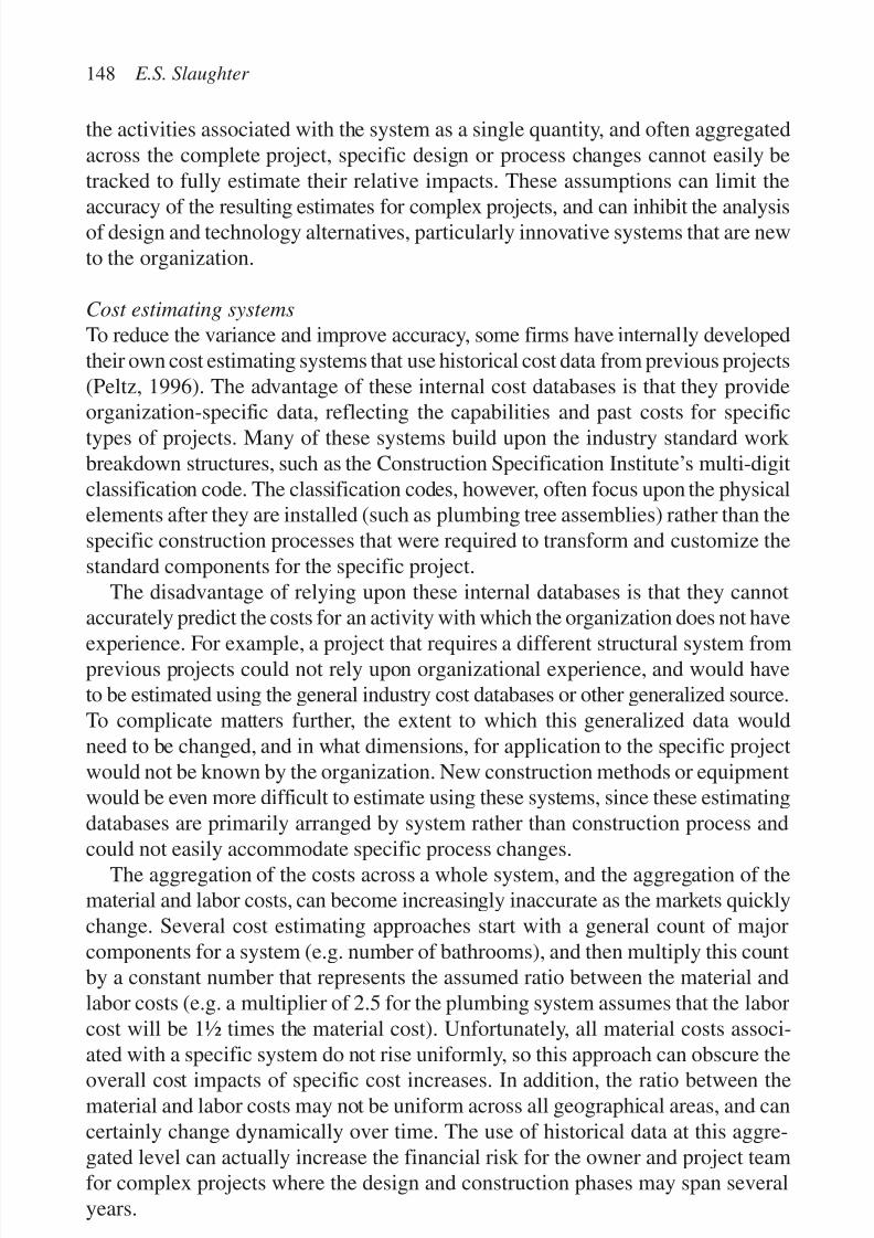
7/14/2019 4DCAD and Visualization in Construction
http://slidepdf.com/reader/full/4dcad-and-visualization-in-construction-56327c6a084e9 157/296
the activities associated with the system as a single quantity, and often aggregatedacross the complete project, specific design or process changes cannot easily betracked to fully estimate their relative impacts. These assumptions can limit the
accuracy of the resulting estimates for complex projects, and can inhibit the analysisof design and technology alternatives, particularly innovative systems that are newto the organization.
Cost estimating systems
To reduce the variance and improve accuracy, some firms have internally developedtheir own cost estimating systems that use historical cost data from previous projects(Peltz, 1996). The advantage of these internal cost databases is that they provideorganization-specific data, reflecting the capabilities and past costs for specifictypes of projects. Many of these systems build upon the industry standard work breakdown structures, such as the Construction Specification Institute’s multi-digitclassification code. The classification codes, however, often focus upon the physicalelements after they are installed (such as plumbing tree assemblies) rather than thespecific construction processes that were required to transform and customize thestandard components for the specific project.
The disadvantage of relying upon these internal databases is that they cannotaccurately predict the costs for an activity with which the organization does not have
experience. For example, a project that requires a different structural system fromprevious projects could not rely upon organizational experience, and would haveto be estimated using the general industry cost databases or other generalized source.To complicate matters further, the extent to which this generalized data wouldneed to be changed, and in what dimensions, for application to the specific projectwould not be known by the organization. New construction methods or equipmentwould be even more difficult to estimate using these systems, since these estimatingdatabases are primarily arranged by system rather than construction process and
could not easily accommodate specific process changes.The aggregation of the costs across a whole system, and the aggregation of the
material and labor costs, can become increasingly inaccurate as the markets quicklychange. Several cost estimating approaches start with a general count of majorcomponents for a system (e.g. number of bathrooms), and then multiply this countby a constant number that represents the assumed ratio between the material andlabor costs (e.g. a multiplier of 2.5 for the plumbing system assumes that the laborcost will be 1½ times the material cost). Unfortunately, all material costs associ-
ated with a specific system do not rise uniformly, so this approach can obscure theoverall cost impacts of specific cost increases. In addition, the ratio between thematerial and labor costs may not be uniform across all geographical areas, and cancertainly change dynamically over time. The use of historical data at this aggre-gated level can actually increase the financial risk for the owner and project teamfor complex projects where the design and construction phases may span severalyears.
148 E.S. Slaughter
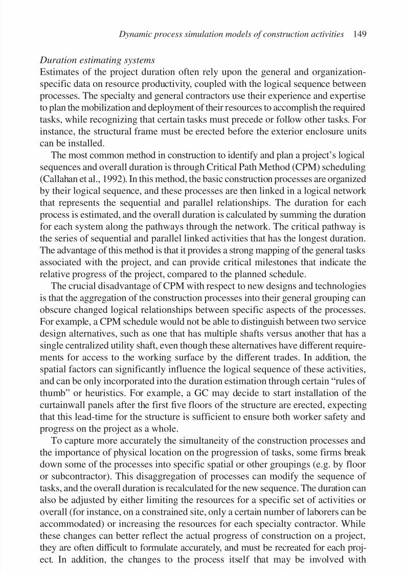
7/14/2019 4DCAD and Visualization in Construction
http://slidepdf.com/reader/full/4dcad-and-visualization-in-construction-56327c6a084e9 158/296
Duration estimating systems
Estimates of the project duration often rely upon the general and organization-specific data on resource productivity, coupled with the logical sequence between
processes. The specialty and general contractors use their experience and expertiseto plan the mobilization and deployment of their resources to accomplish the requiredtasks, while recognizing that certain tasks must precede or follow other tasks. Forinstance, the structural frame must be erected before the exterior enclosure unitscan be installed.
The most common method in construction to identify and plan a project’s logicalsequences and overall duration is through Critical Path Method (CPM) scheduling(Callahan et al., 1992). In this method, the basic construction processes are organizedby their logical sequence, and these processes are then linked in a logical network that represents the sequential and parallel relationships. The duration for eachprocess is estimated, and the overall duration is calculated by summing the durationfor each system along the pathways through the network. The critical pathway isthe series of sequential and parallel linked activities that has the longest duration.The advantage of this method is that it provides a strong mapping of the general tasksassociated with the project, and can provide critical milestones that indicate therelative progress of the project, compared to the planned schedule.
The crucial disadvantage of CPM with respect to new designs and technologies
is that the aggregation of the construction processes into their general grouping canobscure changed logical relationships between specific aspects of the processes.For example, a CPM schedule would not be able to distinguish between two servicedesign alternatives, such as one that has multiple shafts versus another that has asingle centralized utility shaft, even though these alternatives have different require-ments for access to the working surface by the different trades. In addition, thespatial factors can significantly influence the logical sequence of these activities,and can be only incorporated into the duration estimation through certain “rules of
thumb” or heuristics. For example, a GC may decide to start installation of thecurtainwall panels after the first five floors of the structure are erected, expectingthat this lead-time for the structure is sufficient to ensure both worker safety andprogress on the project as a whole.
To capture more accurately the simultaneity of the construction processes andthe importance of physical location on the progression of tasks, some firms break down some of the processes into specific spatial or other groupings (e.g. by flooror subcontractor). This disaggregation of processes can modify the sequence of
tasks, and the overall duration is recalculated for the new sequence. The duration canalso be adjusted by either limiting the resources for a specific set of activities oroverall (for instance, on a constrained site, only a certain number of laborers can beaccommodated) or increasing the resources for each specialty contractor. Whilethese changes can better reflect the actual progress of construction on a project,they are often difficult to formulate accurately, and must be recreated for each proj-ect. In addition, the changes to the process itself that may be involved with
Dynamic process simulation models of construction activities 149
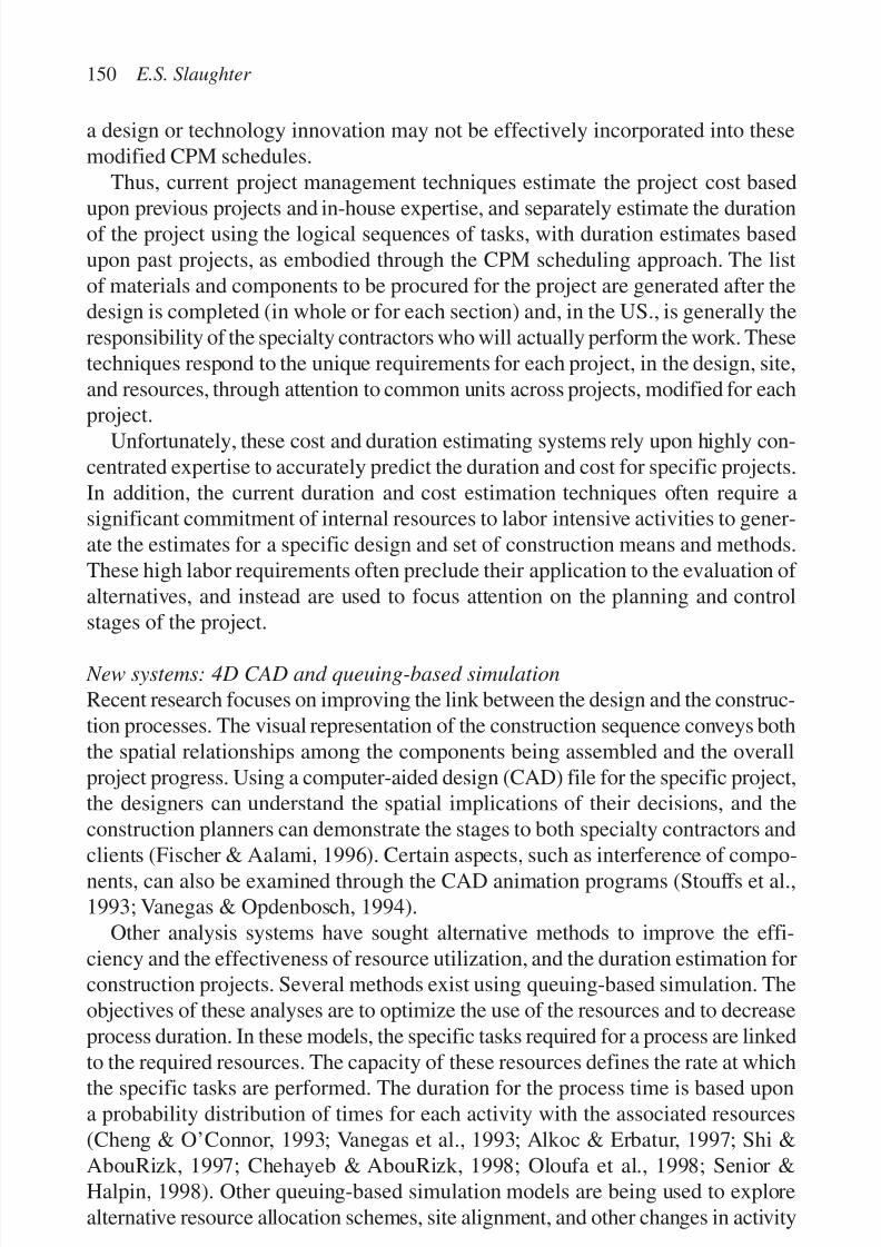
7/14/2019 4DCAD and Visualization in Construction
http://slidepdf.com/reader/full/4dcad-and-visualization-in-construction-56327c6a084e9 159/296
a design or technology innovation may not be effectively incorporated into thesemodified CPM schedules.
Thus, current project management techniques estimate the project cost based
upon previous projects and in-house expertise, and separately estimate the durationof the project using the logical sequences of tasks, with duration estimates basedupon past projects, as embodied through the CPM scheduling approach. The listof materials and components to be procured for the project are generated after thedesign is completed (in whole or for each section) and, in the US., is generally theresponsibility of the specialty contractors who will actually perform the work. Thesetechniques respond to the unique requirements for each project, in the design, site,and resources, through attention to common units across projects, modified for eachproject.
Unfortunately, these cost and duration estimating systems rely upon highly con-centrated expertise to accurately predict the duration and cost for specific projects.In addition, the current duration and cost estimation techniques often require asignificant commitment of internal resources to labor intensive activities to gener-ate the estimates for a specific design and set of construction means and methods.These high labor requirements often preclude their application to the evaluation of alternatives, and instead are used to focus attention on the planning and controlstages of the project.
New systems: 4D CAD and queuing-based simulation
Recent research focuses on improving the link between the design and the construc-tion processes. The visual representation of the construction sequence conveys boththe spatial relationships among the components being assembled and the overallproject progress. Using a computer-aided design (CAD) file for the specific project,the designers can understand the spatial implications of their decisions, and theconstruction planners can demonstrate the stages to both specialty contractors and
clients (Fischer & Aalami, 1996). Certain aspects, such as interference of compo-nents, can also be examined through the CAD animation programs (Stouffs et al.,1993; Vanegas & Opdenbosch, 1994).
Other analysis systems have sought alternative methods to improve the effi-ciency and the effectiveness of resource utilization, and the duration estimation forconstruction projects. Several methods exist using queuing-based simulation. Theobjectives of these analyses are to optimize the use of the resources and to decreaseprocess duration. In these models, the specific tasks required for a process are linked
to the required resources. The capacity of these resources defines the rate at whichthe specific tasks are performed. The duration for the process time is based upona probability distribution of times for each activity with the associated resources(Cheng & O’Connor, 1993; Vanegas et al., 1993; Alkoc & Erbatur, 1997; Shi &AbouRizk, 1997; Chehayeb & AbouRizk, 1998; Oloufa et al., 1998; Senior &Halpin, 1998). Other queuing-based simulation models are being used to explorealternative resource allocation schemes, site alignment, and other changes in activity
150 E.S. Slaughter

7/14/2019 4DCAD and Visualization in Construction
http://slidepdf.com/reader/full/4dcad-and-visualization-in-construction-56327c6a084e9 160/296
relationships (Ioannou & Martinez, 1996; Tommelein, 1998). Emerging simulationmodels using Petri nets and neural networks are also being used to chart the progressof construction activities (Chao & Skibniewski, 1995; Wakefield & Sears, 1997;
Shi, 1999).Using these visualization and simulation models, the construction planners canexplore different combinations and distributions of equipment and other resources,similar to the analyses performed in many manufacturing facilities. These analysescan also explore the impacts of increased or decreased resources on overall progress,as well as the sensitivity of the process to spatial relationships among the designelements. The advantages of these models are that they represent the flow of tasksand activities and their associated resources, and can significantly improve the under-standing of the factors effecting construction progress. The disadvantages are thatthey often have to make assumptions on certain aspects of the construction activities,such as the distribution of the production times, which can limit their applicabilityfor actual construction projects (Schexnayder, 1997). In addition, the task/resourcespecification must often be recreated for each new task, as well as each new project.
New process simulation systems
In several industry sectors, the production process specifics are increasingly rec-ognized as the primary factors defining the economic and technical feasibility of
each new product offering. Simulation of these production processes can providea powerful tool to assess the full context of design and process changes, and toevaluate alternative inputs, processes and methods (Glasscock & Hale, 1994). Inthese dynamic process models, the focus of modeling is on discrete events. Forexample, the location and time at which specific inputs are introduced into theprocess and diverted through the process can determine both the total output quan-tity and the rate of output. The objectives of these simulation models are to betterunderstand the complex interactions between the specific processing stages and
their outputs, and to explore the full system impacts of changing either the inputsor processes.
Dynamic process simulation has clear applicability to the construction industry.Construction processes are complex and dynamic, and the outputs from one stagecan be seen as inputs for subsequent stages, in the transformation and aggregationof components and systems into a built facility. Process simulation could providesignificant benefits to the construction industry, since the construction activitiesdefine both the performance of the construction project and of the completed facil-
ity. The modeling system could provide a means to examine the primary, secondary,and tertiary impacts associated with the introduction of changes into complexinter-dependent processes. However, the context of the construction industry differssignificantly from the chemical process industries, and the processes themselvesdo not share many similarities.
Unlike chemical processing, construction resources can be assigned to manydifferent types of tasks, at many different stages in the processes rather than being
Dynamic process simulation models of construction activities 151

7/14/2019 4DCAD and Visualization in Construction
http://slidepdf.com/reader/full/4dcad-and-visualization-in-construction-56327c6a084e9 161/296
dedicated to a specific set of activities. In addition, unlike the continuous process-ing that is required in chemical plants, construction activities are performed withina project, with a defined beginning and end, to accomplish specific objectives. Each
construction project is by its nature unique, consisting of new combinations of components, systems, and resources to create the facility. The industries also differin their performance measures of the processes. In general, process and manufac-turing industries (and their simulation tools) focus on the process time per unit andoverall process throughput (i.e. the rate at which the units are processed throughthe complete cycle). In contrast, the performance of a construction project is judgedby the cost and duration needed to realize the facility design.
This research developed a construction process simulation system to address theshortcomings of existing estimating techniques, and to provide a tool to directlycalculate the time, cost, and worker safety impacts of design and technology alter-natives. Taking a different approach than the current research in 4D CAD andqueuing-based simulation, this research is strongly complementary to the ongoingefforts in those areas, providing a different view on the link between design andconstruction, focusing particularly on the assessment of specific alternatives withina particular project. The research built upon the process modeling approach usedin the chemical industry, and extended the theoretical framework to accommodatethe specific requirements of the construction industry.
RESEARCH APPROACH
Recent research at MIT has developed the theoretical basis and specific methodolo-gies to systematically assess the construction process impacts of design and technol-
ogy alternatives. The objectives of the research were to characterize constructionprocesses by system and material, and to assess design and technology alternativeswithin systems and across systems in the project as a whole for their impacts onduration, cost, and safety (Slaughter & Eraso, 1997; Slaughter, 1999). The specificresearch methodologies culminated in the creation of specific computer-baseddynamic process simulation models that can be used to evaluate specific designsand technologies for particular projects.
This research resulted in the characterization and model development for 12
system and material-specific construction processes. The models are stored in a“library” of system and material-specific processes, and can be accessed and usedfor any size or type of construction project that employs the process (Table 1). Thefour general systems are the structure, exterior enclosure, services, and interiorfinish. The inter-system links are incorporated in a meta-model for the whole proj-ect, with status and information tracking across each of the systems to representoverall progress.
152 E.S. Slaughter

7/14/2019 4DCAD and Visualization in Construction
http://slidepdf.com/reader/full/4dcad-and-visualization-in-construction-56327c6a084e9 162/296
The modeling system captures the common aspects of each construction process(i.e. tasks and associated resources and the related production rates by specific entity)
while remaining completely adaptable to the elements that differ between projects(i.e. design attributes, number and character of resources), and the dynamic aspectsof each project (e.g. site management strategies) (Fig. 1). Each process model isapplicable across all types and designs of projects and can be immediately applica-ble to a new project or design without recreation or respecification of the tasks andtheir resources, and the sequence of tasks. It also captures the aspects of the designconfiguration of the components, subsystems, and systems that affect the process.
Dynamic process simulation models of construction activities 153
Table 1. Construction process models completed or in process.
System Material-specific model
Structure SteelCast-in-place concreteLight wood framing
Exterior enclosure Precast concrete panelsGlass/metal curtainwall
Services HVAC (heating/ventilation/air conditioning)Hot water heatingPlumbingFire protectionElectrical
Interior finish Interior wallsSuspended ceiling
PROCESS FLOW
-Tasks
-Sequences
-Unit Worked Upon
-Decisions
PROJECT SPECIFICS
- Design Attributes
-Resources
-Production Rates
-Site Conditions
PROJECT DYNAMICS
-Simultaneous tasks
-Shared resources
-Constraints
- Logical- Technical
- Regulatory
SIMULATION
MODEL
Figure 1. Conceptual framework for construction process modeling system.
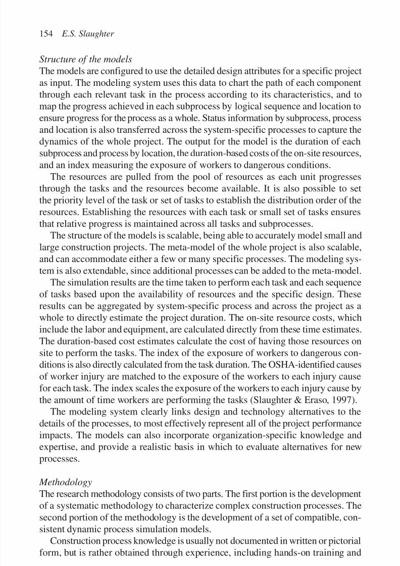
7/14/2019 4DCAD and Visualization in Construction
http://slidepdf.com/reader/full/4dcad-and-visualization-in-construction-56327c6a084e9 163/296
Structure of the models
The models are configured to use the detailed design attributes for a specific projectas input. The modeling system uses this data to chart the path of each component
through each relevant task in the process according to its characteristics, and tomap the progress achieved in each subprocess by logical sequence and location toensure progress for the process as a whole. Status information by subprocess, processand location is also transferred across the system-specific processes to capture thedynamics of the whole project. The output for the model is the duration of eachsubprocess and process by location, the duration-based costs of the on-site resources,and an index measuring the exposure of workers to dangerous conditions.
The resources are pulled from the pool of resources as each unit progressesthrough the tasks and the resources become available. It is also possible to setthe priority level of the task or set of tasks to establish the distribution order of theresources. Establishing the resources with each task or small set of tasks ensuresthat relative progress is maintained across all tasks and subprocesses.
The structure of the models is scalable, being able to accurately model small andlarge construction projects. The meta-model of the whole project is also scalable,and can accommodate either a few or many specific processes. The modeling sys-tem is also extendable, since additional processes can be added to the meta-model.
The simulation results are the time taken to perform each task and each sequence
of tasks based upon the availability of resources and the specific design. Theseresults can be aggregated by system-specific process and across the project as awhole to directly estimate the project duration. The on-site resource costs, whichinclude the labor and equipment, are calculated directly from these time estimates.The duration-based cost estimates calculate the cost of having those resources onsite to perform the tasks. The index of the exposure of workers to dangerous con-ditions is also directly calculated from the task duration. The OSHA-identified causesof worker injury are matched to the exposure of the workers to each injury cause
for each task. The index scales the exposure of the workers to each injury cause bythe amount of time workers are performing the tasks (Slaughter & Eraso, 1997).
The modeling system clearly links design and technology alternatives to thedetails of the processes, to most effectively represent all of the project performanceimpacts. The models can also incorporate organization-specific knowledge andexpertise, and provide a realistic basis in which to evaluate alternatives for newprocesses.
MethodologyThe research methodology consists of two parts. The first portion is the developmentof a systematic methodology to characterize complex construction processes. Thesecond portion of the methodology is the development of a set of compatible, con-sistent dynamic process simulation models.
Construction process knowledge is usually not documented in written or pictorialform, but is rather obtained through experience, including hands-on training and
154 E.S. Slaughter
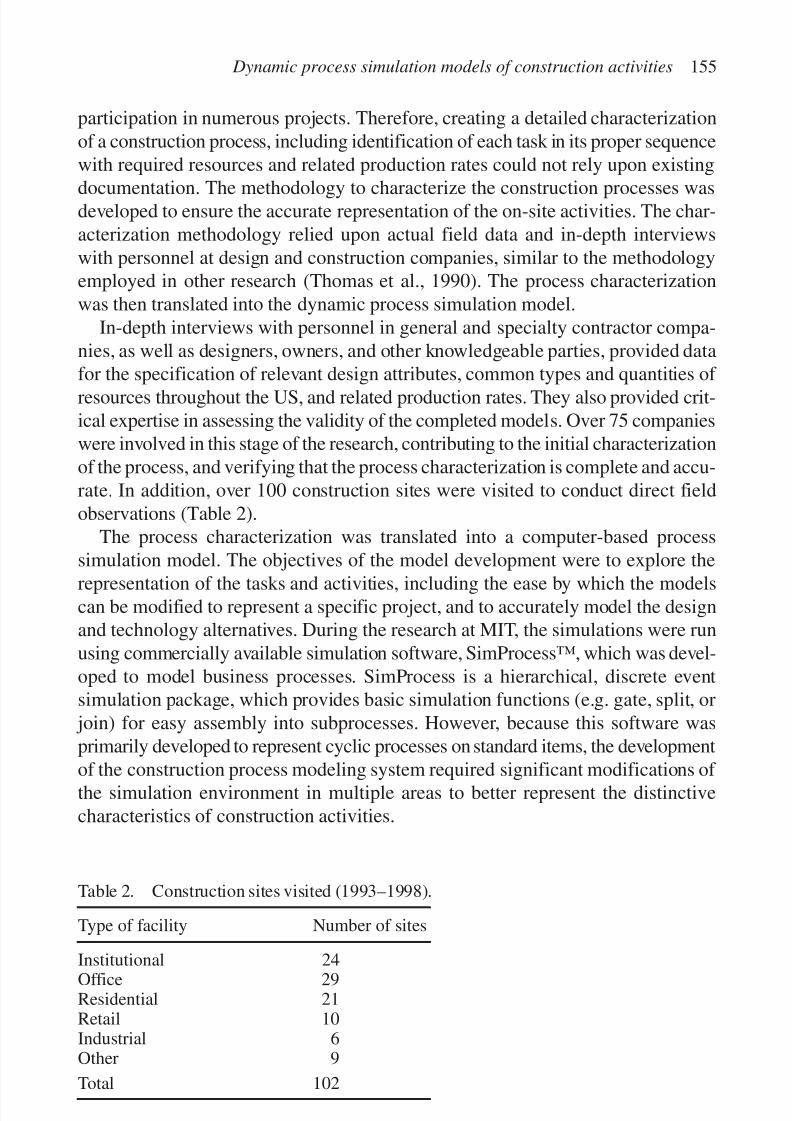
7/14/2019 4DCAD and Visualization in Construction
http://slidepdf.com/reader/full/4dcad-and-visualization-in-construction-56327c6a084e9 164/296
participation in numerous projects. Therefore, creating a detailed characterizationof a construction process, including identification of each task in its proper sequencewith required resources and related production rates could not rely upon existing
documentation. The methodology to characterize the construction processes wasdeveloped to ensure the accurate representation of the on-site activities. The char-acterization methodology relied upon actual field data and in-depth interviewswith personnel at design and construction companies, similar to the methodologyemployed in other research (Thomas et al., 1990). The process characterizationwas then translated into the dynamic process simulation model.
In-depth interviews with personnel in general and specialty contractor compa-nies, as well as designers, owners, and other knowledgeable parties, provided datafor the specification of relevant design attributes, common types and quantities of resources throughout the US, and related production rates. They also provided crit-ical expertise in assessing the validity of the completed models. Over 75 companieswere involved in this stage of the research, contributing to the initial characterizationof the process, and verifying that the process characterization is complete and accu-rate. In addition, over 100 construction sites were visited to conduct direct fieldobservations (Table 2).
The process characterization was translated into a computer-based processsimulation model. The objectives of the model development were to explore the
representation of the tasks and activities, including the ease by which the modelscan be modified to represent a specific project, and to accurately model the designand technology alternatives. During the research at MIT, the simulations were runusing commercially available simulation software, SimProcess™, which was devel-oped to model business processes. SimProcess is a hierarchical, discrete eventsimulation package, which provides basic simulation functions (e.g. gate, split, or
join) for easy assembly into subprocesses. However, because this software wasprimarily developed to represent cyclic processes on standard items, the development
of the construction process modeling system required significant modifications of the simulation environment in multiple areas to better represent the distinctivecharacteristics of construction activities.
Dynamic process simulation models of construction activities 155
Table 2. Construction sites visited (1993–1998).
Type of facility Number of sites
Institutional 24Office 29Residential 21Retail 10Industrial 6Other 9
Total 102

7/14/2019 4DCAD and Visualization in Construction
http://slidepdf.com/reader/full/4dcad-and-visualization-in-construction-56327c6a084e9 165/296
The model results for a specific building design were sent to industry experts toassess the accuracy of the results, and in every case the model results were within1–5% of industry duration and cost estimates. The specific system design for each
construction process was also defined to reflect a representative building type, andwas reviewed by relevant designers. The development of each process simulationmodel has taken 18–24 months, including the estimation of results for the proto-type building, and calibration to accurately reflect actual project performance.
These results become the baseline against which selected scenarios are compared,to analyze the relative system-level impacts of alternative designs and technologies.The scenarios can also be used to analyze the attributes of specific proposed designand technology innovations, to identify certain characteristics that may increase ordecrease the expected benefits and to influence the development of more appro-priate construction innovations. In addition, the scenarios can be used to explorepotential complementary aspects of alternatives, when a combination of innova-tions may provide greater benefits than the sum of the individual innovations.
Design and process links
The modeling system provides explicit links between the design and the constructionprocess at many different levels. These levels include the specific components,their subsystem and systems, and the specific configuration of the components and
systems spatially and temporally for a particular project. It also provides a commonbasis in which the design and construction team can plan and coordinate the con-struction activities, and reconcile the design and construction objectives. As clientsincrease their requirements for high quality facilities obtained at a reasonable priceand within shorter durations, design and construction professionals increasinglyrecognize the incentives to work together.
The design is linked to the process through the type and quantities of the compo-nents, and also through their configuration. For instance, if a pipe run is a straight
line between the riser and the fixture, there are fewer connections than a pipe runwith multiple bends. As a result, the straight run will take less time to place andconnect, which will influence the progress of the process as a whole. In some cases,the progress on that particular location in the building may be critical to the progressfor subsequent processes, and the time to place and connect the pipe lengths forthe run can directly influence the overall project performance.
The spatial relationships of the design elements also influence the overall time,cost, and worker safety of the project. For example, for a floor of an office building,
the restroom facilities could be centralized in one area, or separated into severalzones. These design alternatives could be used for one, several, or all floors, andthe relative costs and time for each design alternative will differ, depending uponthe design alternative selected for each system for each floor and the relationshipto the contiguous floors. Since the plumbing must be installed before the interiorfinish can be placed for those rooms, and the interior finish must be completebefore the fixtures are installed, the design layout of the facilities determines the
156 E.S. Slaughter

7/14/2019 4DCAD and Visualization in Construction
http://slidepdf.com/reader/full/4dcad-and-visualization-in-construction-56327c6a084e9 166/296
rate at which the restroom facilities are completed for each floor, which in turndetermines the completion time for the project as a whole.
LINKED DESIGN AND PROCESS CHANGES: SIMULATION RESULTS
The duration, cost, and safety results are calculated for a specific project, for eachdesign alternative or set of alternatives. Examples of the representation of the linksbetween the design and process are discussed here for several different systems(i.e. structural system, exterior enclosure system, and services system) with thesimulation results to demonstrate the applicability of the research approach to actualconstruction projects.
The baseline for the analysis is a five-story office building, with a footprint of 30.5 by 38 m (100 by 125 feet), with the floor-to-floor height of 3 m (10 feet) anda bay size of 7.6 by 7.6 m (25 by 25 feet) (Fig. 2). The structural system describedhere is cast-in-place reinforced concrete columns and beams with a two-way slabof 200 mm (8 inches) (Carr, 1998; Slaughter & Carr, 1999). The exterior enclosuresystem analyzed here is glass curtainwall system (Attai, 1997; Slaughter, 1997).The service system described here is a domestic plumbing system, including hot
and cold potable water with a drain, waste, and vent outflow (Murray, 1999).
Cast-in-place reinforced concrete structure results
Significant on-site resources are required to construct a cast-in-place reinforcedconcrete structure. While this structural type performs very well under extremeloads (such as seismic conditions), it does take many direct labor hours to fabricate
Dynamic process simulation models of construction activities 157
7.6 m
7.6 m Columns Beams
Service Core
Figure 2. Floor plan for prototype building.
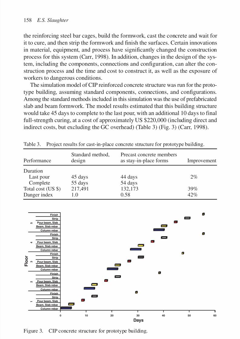
7/14/2019 4DCAD and Visualization in Construction
http://slidepdf.com/reader/full/4dcad-and-visualization-in-construction-56327c6a084e9 167/296
the reinforcing steel bar cages, build the formwork, cast the concrete and wait forit to cure, and then strip the formwork and finish the surfaces. Certain innovationsin material, equipment, and process have significantly changed the construction
process for this system (Carr, 1998). In addition, changes in the design of the sys-tem, including the components, connections and configuration, can alter the con-struction process and the time and cost to construct it, as well as the exposure of workers to dangerous conditions.
The simulation model of CIP reinforced concrete structure was run for the proto-type building, assuming standard components, connections, and configurations.Among the standard methods included in this simulation was the use of prefabricatedslab and beam formwork. The model results estimated that this building structurewould take 45 days to complete to the last pour, with an additional 10 days to finalfull-strength curing, at a cost of approximately US $220,000 (including direct andindirect costs, but excluding the GC overhead) (Table 3) (Fig. 3) (Carr, 1998).
158 E.S. Slaughter
Finish
Strip
Pour beam, Slab
Pour beam, Slab
Beam, Slab rebar
Beam, Slab rebar
Column rebar
Column rebar
Finish
Strip
Pour beam, Slab
Beam, Slab rebar
Column rebar
Finish
Strip
Pour beam, Slab
Beam, Slab rebar
Column rebar
Finish
Strip
Pour beam, Slab
Beam, Slab rebar
Column rebar
Finish
Strip
F l o o r
1
2
3
4
5
0 10 20 30
Days
40 50 60
Figure 3. CIP concrete structure for prototype building.
Table 3. Project results for cast-in-place concrete structure for prototype building.
Standard method, Precast concrete membersPerformance design as stay-in-place forms Improvement
DurationLast pour 45 days 44 days 2%Complete 55 days 54 days
Total cost (US $) 217,491 132,173 39%Danger index 1.0 0.58 42%
7/14/2019 4DCAD and Visualization in Construction
http://slidepdf.com/reader/full/4dcad-and-visualization-in-construction-56327c6a084e9 168/296
Throughout the CIP concrete industry, interest has been increasing on the poten-tial savings that may be available from use of prefabricated and/or stay-in-placeformwork. Therefore, the design and process specifics for the prototype building
were modified to analyze this alternative. Specifically, the structural slab and beammembers are redesigned to include precast concrete panels and members withimbedded reinforcing steel. The precast concrete elements are supplemented byfield-placed reinforcing steel and concrete to reach the full depth and strengthrequired to meet the design load requirements.
The primary impact of the use of the precast concrete members (as stay-in-placeforms) is to eliminate the stripping of the formwork. However, because this activityis performed simultaneously with other construction activities, the reduction inprocess duration is minor, at approximately 2% reduction in duration (Table 3).Interestingly, the major time reduction is primarily due to the elimination of plac-ing steel reinforcing bars in the bottom layer of the members.
The secondary and tertiary impacts of this alternative are much more significant,however. Since the stay-in-place formwork eliminates several steps, the formwork crew can be re-assigned to other activities, and can complete those activities inless time (and, therefore, for almost 40% lower cost). This reassignment of workersto different tasks, and particularly the elimination of the stripping stages, significantlyreduces the exposure of the workers to dangerous conditions (by 42%), since they
are no longer required to move large panels of formwork from under the cast slabsand beams during the formwork stripping stage.
These impacts from the design alternative of precast concrete members as stay-in-place formwork would not be readily apparent without the detailed analysis link of the design to the specific process activities and resources, available through theprocess simulation models.
Domestic plumbing service system results
Domestic plumbing systems, which supply hot and cold water and remove the waste,are required for all occupied facilities. The supply and drain/waste/vent systemform a closed loop system, and the point of transfer between the supply and returnsystems is the plumbing fixtures (e.g. sink, toilet, or appliance). The vertical supplyunits are called the risers, the vertical return units are called stacks (and usuallyrely upon a gravity-based flow), and these subsystems each have horizontal pipingto and from the fixtures. The vent element is included with the return system to equal-ize the pressure in the system to allow the waste to flow freely down the stacks.
Certain building codes require different configurations of vent elements for differenttypes and configurations of fixtures, and these venting requirements can consistof several separate stack elements, as well as the activities needed to install andconnect them.
The plumbing design for the prototype building has one major shaft for the stacksand risers. Each floor has two restrooms placed in close proximity to the shaft,each with three sinks and four toilets and/or urinals and a drinking fountain in the
Dynamic process simulation models of construction activities 159

7/14/2019 4DCAD and Visualization in Construction
http://slidepdf.com/reader/full/4dcad-and-visualization-in-construction-56327c6a084e9 169/296
hall. The simulation model of plumbing installation was run for this building design,and the model results estimate that it would take 36 days, at a cost of approximatelyUS $105,000 (including direct and indirect costs, but excluding the GC overhead)
(Table 4) (Fig. 4) (Murray, 1999).One design alternative is to install a mechanical aeration device within the waste
return system to actively equalize the pressure in the waste pipes and stacks. Thisdevice could eliminate the venting units for a medium-sized occupied building.Since the vertical venting units are usually integrated with the waste stacks, and thehorizontal venting loops are usually only a small portion of the horizontal pipes,the primary impact of this design alternative is minimal, with small reductions inthe plumbing installation process.
The secondary and tertiary impacts of this alternative are quite significant.Because the installation and connection of the venting units is usually performedin close physical proximity to the other vertical and horizontal piping elements,the elimination of these units can considerably simplify the placement and connec-tion of the remaining units. This simplification can reduce the time and cost of theprocess significantly, allowing the workers to progress more efficiently for each
160 E.S. Slaughter
Figure 4. Plumbing results for prototype building.
Table 4. Project results for plumbing system for prototype building.
Performance Standard Method, design Aerator Improvement
Duration 36 days 30 days 17%Total cost (US $) 104,976 89,100 15%Danger index 1.0 1.0 0%
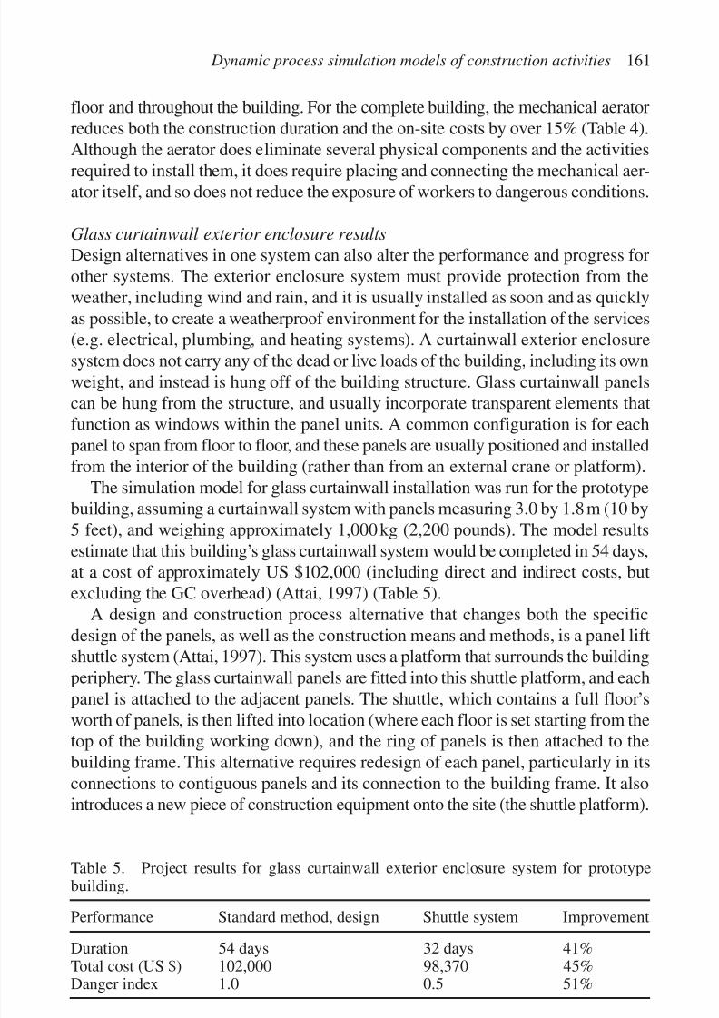
7/14/2019 4DCAD and Visualization in Construction
http://slidepdf.com/reader/full/4dcad-and-visualization-in-construction-56327c6a084e9 170/296
floor and throughout the building. For the complete building, the mechanical aeratorreduces both the construction duration and the on-site costs by over 15% (Table 4).Although the aerator does eliminate several physical components and the activities
required to install them, it does require placing and connecting the mechanical aer-ator itself, and so does not reduce the exposure of workers to dangerous conditions.
Glass curtainwall exterior enclosure results
Design alternatives in one system can also alter the performance and progress forother systems. The exterior enclosure system must provide protection from theweather, including wind and rain, and it is usually installed as soon and as quicklyas possible, to create a weatherproof environment for the installation of the services(e.g. electrical, plumbing, and heating systems). A curtainwall exterior enclosuresystem does not carry any of the dead or live loads of the building, including its ownweight, and instead is hung off of the building structure. Glass curtainwall panelscan be hung from the structure, and usually incorporate transparent elements thatfunction as windows within the panel units. A common configuration is for eachpanel to span from floor to floor, and these panels are usually positioned and installedfrom the interior of the building (rather than from an external crane or platform).
The simulation model for glass curtainwall installation was run for the prototypebuilding, assuming a curtainwall system with panels measuring 3.0 by 1.8 m (10 by
5 feet), and weighing approximately 1,000 kg (2,200 pounds). The model resultsestimate that this building’s glass curtainwall system would be completed in 54 days,at a cost of approximately US $102,000 (including direct and indirect costs, butexcluding the GC overhead) (Attai, 1997) (Table 5).
A design and construction process alternative that changes both the specificdesign of the panels, as well as the construction means and methods, is a panel liftshuttle system (Attai, 1997). This system uses a platform that surrounds the buildingperiphery. The glass curtainwall panels are fitted into this shuttle platform, and each
panel is attached to the adjacent panels. The shuttle, which contains a full floor’sworth of panels, is then lifted into location (where each floor is set starting from thetop of the building working down), and the ring of panels is then attached to thebuilding frame. This alternative requires redesign of each panel, particularly in itsconnections to contiguous panels and its connection to the building frame. It alsointroduces a new piece of construction equipment onto the site (the shuttle platform).
Dynamic process simulation models of construction activities 161
Table 5. Project results for glass curtainwall exterior enclosure system for prototypebuilding.
Performance Standard method, design Shuttle system Improvement
Duration 54 days 32 days 41%Total cost (US $) 102,000 98,370 45%Danger index 1.0 0.5 51%
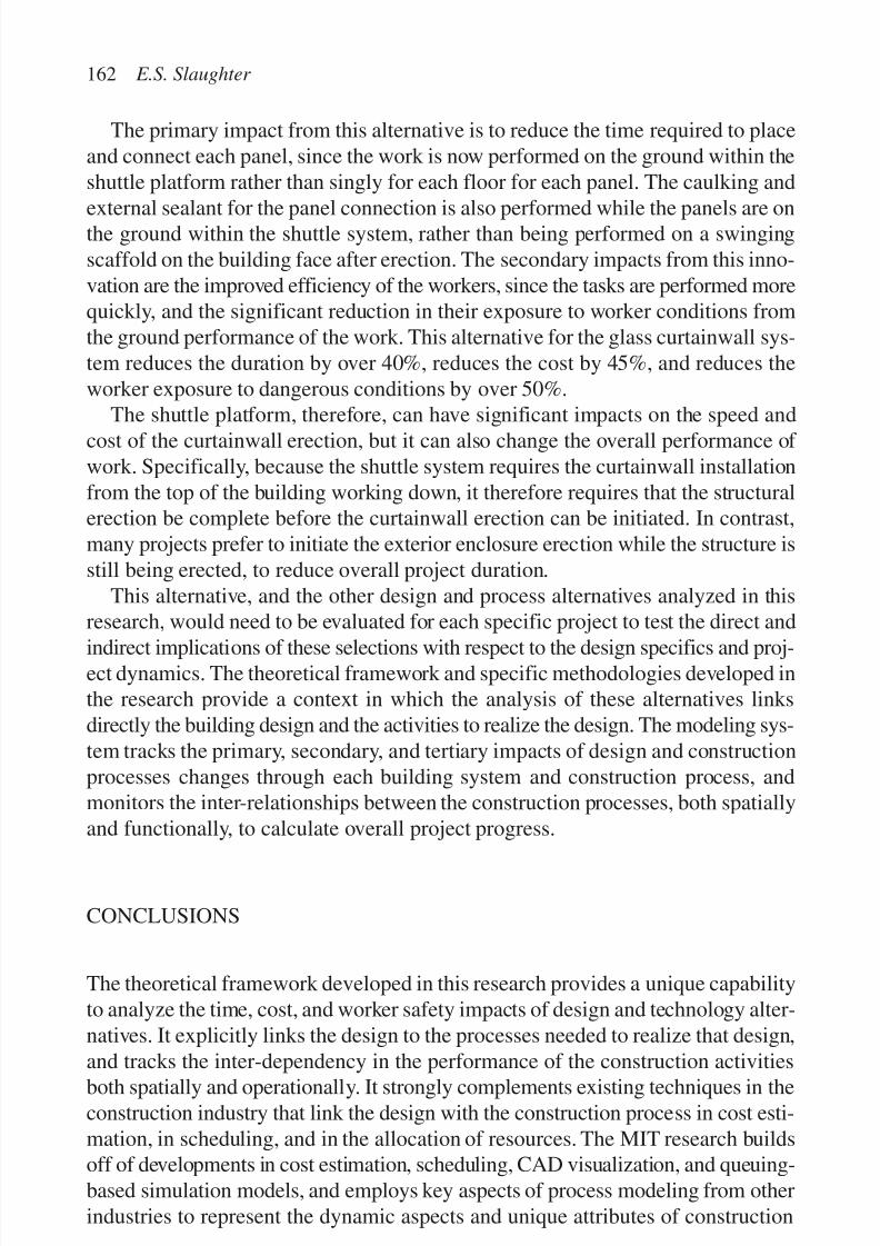
7/14/2019 4DCAD and Visualization in Construction
http://slidepdf.com/reader/full/4dcad-and-visualization-in-construction-56327c6a084e9 171/296
The primary impact from this alternative is to reduce the time required to placeand connect each panel, since the work is now performed on the ground within theshuttle platform rather than singly for each floor for each panel. The caulking and
external sealant for the panel connection is also performed while the panels are onthe ground within the shuttle system, rather than being performed on a swingingscaffold on the building face after erection. The secondary impacts from this inno-vation are the improved efficiency of the workers, since the tasks are performed morequickly, and the significant reduction in their exposure to worker conditions fromthe ground performance of the work. This alternative for the glass curtainwall sys-tem reduces the duration by over 40%, reduces the cost by 45%, and reduces theworker exposure to dangerous conditions by over 50%.
The shuttle platform, therefore, can have significant impacts on the speed andcost of the curtainwall erection, but it can also change the overall performance of work. Specifically, because the shuttle system requires the curtainwall installationfrom the top of the building working down, it therefore requires that the structuralerection be complete before the curtainwall erection can be initiated. In contrast,many projects prefer to initiate the exterior enclosure erection while the structure isstill being erected, to reduce overall project duration.
This alternative, and the other design and process alternatives analyzed in thisresearch, would need to be evaluated for each specific project to test the direct and
indirect implications of these selections with respect to the design specifics and proj-ect dynamics. The theoretical framework and specific methodologies developed inthe research provide a context in which the analysis of these alternatives linksdirectly the building design and the activities to realize the design. The modeling sys-tem tracks the primary, secondary, and tertiary impacts of design and constructionprocesses changes through each building system and construction process, andmonitors the inter-relationships between the construction processes, both spatiallyand functionally, to calculate overall project progress.
CONCLUSIONS
The theoretical framework developed in this research provides a unique capabilityto analyze the time, cost, and worker safety impacts of design and technology alter-natives. It explicitly links the design to the processes needed to realize that design,
and tracks the inter-dependency in the performance of the construction activitiesboth spatially and operationally. It strongly complements existing techniques in theconstruction industry that link the design with the construction process in cost esti-mation, in scheduling, and in the allocation of resources. The MIT research buildsoff of developments in cost estimation, scheduling, CAD visualization, and queuing-based simulation models, and employs key aspects of process modeling from otherindustries to represent the dynamic aspects and unique attributes of construction
162 E.S. Slaughter

7/14/2019 4DCAD and Visualization in Construction
http://slidepdf.com/reader/full/4dcad-and-visualization-in-construction-56327c6a084e9 172/296
processes. The general objectives of the research are to improve the efficiency andeffectiveness of the construction of facilities, specifically through improving thelink between design and the construction process.
The immediate potential link of design to construction is use of the modeling sys-tem by designers, CMs, and general and specialty contractors to analyze design andtechnology alternatives to improve their planning and control capabilities. Thesecompanies could use the models for a specific project to analyze their processesand understand the nature of their activities and the impact that design and tech-nology alternatives would have on their operations and costs.
As the design and process links improve, the variation and uncertainty associatedwith each project could diminish, thereby reducing the actual and perceived risk associated with most construction projects. In addition, the new links between designand process can create an environment in which the costs and benefits associatedwith each design and technology alternative are better understood and can be explic-itly distributed among the project participants. Innovations in design and technology,as well as new design configurations, can be assessed directly for their impacts onthe construction process for each specific construction project. These analyses pro-vide a critical feedback system for design and construction organizations to learnacross projects to improve their internal competencies. It also provides a means toassess and improve the designs, components, systems, and process of construction
projects, as well as to improve the efficiency of the design and construction processes.
REFERENCES
Alkoc, E. & Erbatur, F. 1997. Productivity improvement in concreting operations throughsimulation models. Building Research and Information 25(2): 82–91.
Attai, L.M. 1997. Simulation to assess exterior enclosure innovations. Master of Science,Massachusetts Institute of Technology, Cambridge, MA.
Callahan, M.T., Quackenbush, D.G. & Rowings, J.E. 1992. Construction project scheduling. New York: McGraw-Hill.
Carr, M.N. 1998. Simulation to assess cast-in-place concrete construction innovation.Master of Science, Massachusetts Institute of Technology, Cambridge, MA.
Chao, L.-C. & Skibniewski, M.J. 1995. Neural network method of estimating constructiontechnology acceptability. Journal of Construction Engineering and Management 121(1):130–142.
Chehayeb, N.N. & AbouRizk, S.M. 1998. Simulation-based scheduling with continuousactivity relationships. Journal of Construction Engineering and Management 124(2):107–115.
Cheng, M.Y. & O’Connor, J.T. 1993. Simulation analysis of process piping construction. Automation and robotics in construction X . Elsevier Science Publishers: 519–526.
Eraso, M. 1995. Methodology for the economic assessment of construction innovations:simulation of structural steel erection. Master of Science, Lehigh University,Bethlehem, PA.
Dynamic process simulation models of construction activities 163

7/14/2019 4DCAD and Visualization in Construction
http://slidepdf.com/reader/full/4dcad-and-visualization-in-construction-56327c6a084e9 173/296
Fischer, M.A. & Aalami, F. 1996. Scheduling with computer-interpretable constructionmethod models. Journal of Construction Engineering and Management 122(4): 337–347.
Glasscock, D.A. & Hale, J.C. 1994. Process simulation: the art and science of modeling.Chemical Engineering 101(11): 82–89.
Ioannou, P.G. & Martinez, J.C. 1996. Comparison of construction alternatives using matchedsimulation experiments. Journal of Construction Engineering and Management 122(3):231–241.
Murray, J. 1999. Simulation to assess innovations in the installation of plumbing and fire protection systems. Master of Science, Massachusetts Institute of Technology,Cambridge, MA.
Oloufa, A.A., Ikeda, M. & Nguyen, T.H. 1998. Resource-based simulation libraries forconstruction. Automation in Construction 7: 315–326.
Peltz, C. 1996. Model estimating in design-build. Construction Business Review6(2): 48–50.
Schexnayder, C.J. 1997. Analysis of earth-moving systems discrete-event simulation:discussion. Journal of Construction Engineering and Management 123(2): 199.
Senior, B.A. & Halpin, D.W. 1998. Simplified simulation system for constructionprojects. Journal of Construction Engineering and Management 124(1): 72–81.
Shi, J. & AbouRizk, S.M. 1997. Resource-based modeling for construction simulation. Journal of Construction Engineering and Management 123(1): 26–33.
Shi, J.J. 1999. A neural network based system for predicting earthmoving production.Construction Management and Economics 17(4): 463–471.
Slaughter, E.S. 1997. Computer-based process simulation of construction activities.
Construction Congress. Minneapolis, MN. ASCE, New York.Slaughter, E.S. & Eraso, M. 1997. Simulation of structural steel erection to assessinnovations. IEEE Transactions on Engineering Management 44(2): 196–207.
Slaughter, E.S. 1999. Assessment of construction processes and innovations throughsimulation. Construction Management and Economics 17(3): 341–350.
Slaughter, E.S. & Carr, M.N. 1999. Dynamic process simulation model of cast-in-placeconcrete process. Structures Congress. New Orleans, LA. ASCE, New York.
Stouffs, R., Krishnamurti, R., Lee, S. & Oppenheim, I. 1993. Construction processsimulation with rule-base robot path planning. Automation and robotics inconstruction X . Elsevier Science Publishers: 495–502.
Thomas, H.R., Horner, R.M. & Smith, G.R. 1990. Procedures manual for collecting productivity and related data of labor-intensive activities on commercial construction projects: Structural steel. Pennsylvania Transportation Institute, University of Pennsylvania, State College, PA.
Tommelein, I.D. 1998. Pull-driven scheduling for pipe-spool installation: simulation of lean construction technique. Journal of Construction Engineering and Management 124(4): 279–288.
Vanegas, J.A., Bravo, E.B. & Halpin, D.W. 1993. Simulation technologies for planningheavy construction processes. Journal of Construction Engineering and Management 119(2): 336–354.
Vanegas, J.A. & Opdenbosch, A. 1994. Using simulation and visualization technologiesto strengthen the design/construction interface. 1994 winter simulation conference:1137–1144.
Wakefield, R.R. & Sears, G.A. 1997. Petri nets for simulation and modeling of constructionsystems. Journal of Construction Engineering and Management 123(2): 105–112.
164 E.S. Slaughter
7/14/2019 4DCAD and Visualization in Construction
http://slidepdf.com/reader/full/4dcad-and-visualization-in-construction-56327c6a084e9 174/296
ACKNOWLEDGING VARIABILITY AND UNCERTAINTYIN PRODUCT AND PROCESS DEVELOPMENT
Iris D. Tommelein
Construction Engineering and Management Program, Civil and Environmental
Engineering Department, University of California, Berkeley, CA, USA
165
Abstract
Four-dimensional (4D) models describe product geometry in three dimensions and process
time in one dimension. Most 4D models in use today do not explicitly reflect that the values
taken on by geometric and temporal variables may not be known exactly, but can vary for a
variety of reasons such as human indecision or physical tolerances. Moreover, practitioners
involved in product and process development for the architecture/engineering/construction
industry need to reason about numerous other variables in addition to those regarding timeand space. As a result, 4D models support their endeavors only in part. This paper describes
sources of variability and uncertainty in product- as well as process-definition. It then argues
for developing and using representations that lend themselves to studying the impact of
variability and uncertainty on the integrated product- and process-development process.
Reasoning is biased by the conceptualization and representation people choose to adopt.
People’s problem-solving abilities are biased in a similar way. A world in which no variation
or uncertainty is recognized gets modeled deterministically, often by means of expected val-
ues. Models based on averages are unrealistically optimistic. Single values reflecting early
commitment tend to lead to process iteration. This paper therefore argues for the creation andstudy of extended 4D models, referred to as 4Dϩ, that explicitly represent alternative sets,
interdependence, variability, and uncertainty. Examples illustrate what features are neces-
sary in 4Dϩ representations to make it possible to perform concurrent engineering and to
manage the production system that supports integrated product and process development.
Keywords: integrated product and process development, 4D modeling, lean construction,
supply chain management, design, production planning, simulation, interdependence,
uncertainty, AEC, concurrent engineering, set-based design
INTRODUCTION
Four-dimensional (4D) models describe product geometry in three dimensionsand process time in one dimension. Though generally well understood, 4D refers

7/14/2019 4DCAD and Visualization in Construction
http://slidepdf.com/reader/full/4dcad-and-visualization-in-construction-56327c6a084e9 175/296
to a range of different conceptualizations and associated models. This will alreadybe clear to the reader who has reviewed the various papers of this book.
HISTORIC BACKGROUND
4D models are the product of a long evolution in computer modeling. While earlycomputer input and output was type-based, the need for and benefits of providinggraphical output soon became apparent. Three-dimensional (3D) viewing was madepossible by “Evans and Sutherland (who) demonstrated a head mounted stereodisplay as early as in 1965” (mentioned in Issa et al., 1999) in order to create anenvironment of virtual reality. Vector-based “graphical” monitors were created toavoid the jagged lines displayed on low-resolution type- and raster-based monitors.Still facing limited computational power in the 1970s, graphics programmers werechallenged by the desire to provide hidden-line elimination, which was necessaryfor realistic image rendering.
As early as the 1950s when computers became available, algorithms wereprogrammed to solve numeric problems. Pioneers in civil engineering soon per-formed structural analysis and other decision support as well as automation tasks
using computers (Levitt, 1995; iii–v). Likewise in the 1950s, neural nets were con-ceived of (though not much researched due to lack of funding) and list-processinglanguages based on the mathematics of rule-based logic were implemented to sup-port non-numeric processing. The 1960s were a prolific time in terms of developmentof new computing practices. Programmers in the field of Artificial Intelligence(AI) ambitiously developed a “general problem-solver” called GPS (Simon, 1996),object-oriented programming (OOP) languages came about, and the Internet wasestablished. Soon Xerox PARC played a key role in prototyping new ways for
people to interface with their computers (e.g. the SmallTalk OOP language and themouse were invented there). The notion of blackboard systems developed in thelate 1970s (Nii, 1986a, b). Their problem-solving ability relied upon distributed,complementary yet competing knowledge sources, and thereby allowed for prob-lem solving to go on simultaneously at different levels of abstraction. Alternativeblackboard architectures emerged in the 1980s (Hayes-Roth, 1985; Durfee, 1988).They are the predecessors to agent-based and later web-based systems.
The early 1980s saw the birth of personal computers, which not only made com-
puting more accessible to the masses but also stimulated the development of localarea networks to ease communication and data transfer. This started an era forintegration of stand-alone programs (e.g. Tommelein, 1995a) so characteristic of our fragmented industry (Howard et al., 1989).
As for computer modeling in architecture/engineering/construction (AEC) prac-tice, large engineering and construction firms such as Bechtel purchased softwareand hardware capabilities in the mid-1980s in order to develop their proprietary
166 I.D. Tommelein

7/14/2019 4DCAD and Visualization in Construction
http://slidepdf.com/reader/full/4dcad-and-visualization-in-construction-56327c6a084e9 176/296
3D capabilities and then extend it into a WalkThru™ environment, a direct prede-cessor of today’s 4D models. Other companies such as Stone&Webster tailoredoff-the-shelf computing environments used in the automobile industry (i.e. Catia)
to their own needs. Today’s models allow for parametric design (e.g. Revit, 2001).Processors with ever-increasing speeds and better display technologies at increas-ingly competitive prices have since flooded the market with computing capa-bilities. Further miniaturization, from desktops to laptops, then on to palmtopsand cellular telephone devices, has made computing today truly ubiquitous. Theexplosion in popularity of the world wide web and OOP languages such as Java,allowing for distributed, collaborative problem solving using applets, has spurredthe development of applications that could only be dreamt of a few years ago.
AEC researchers, teachers, and practitioners have barely begun to scratch thesurface of what is computationally possible with today’s hardware and software.As an industry, we are all too often conservative and focused on individual proj-ects. Project economics using traditional yardsticks have only on occasion beenfavorable with respect to promoting the use of cutting-edge practices, includinginnovative management practices or adoption of the latest computer technologies.Today’s computer capabilities are rarely—if at all—holding us back from improv-ing, or—better even—radically reinventing our work processes. The benefit/costratios for adopting new practices are shifting, thanks to not only current market
pricing and availability of hardware and software, but more importantly due toincreasing demand by project owners for added complexity and reliable perform-ance of the facilities that are designed and built. Accordingly, spending more timeon prototyping parts of an AEC facility (or the entire facility), prior to construc-tion yields advantage internally to the involved organization and may provide theorganization with external competitive advantage. It is within this context that 4Dmodeling plays an important role.
The true power of 4D modeling as compared to 3D CAD is that by extending
geometry with time, the opportunity is created for planning. Planning means giv-ing consideration to alternative means and methods, alternative durations of activ-ities, and alternative times and sequences in which to perform them. The planningtask that involves space is not an easy one, however. Most resources considered intraditional planning are scalar (e.g. labor and staffing, equipment, materials, money,and time). Depending on the purpose for which the model will be used, space mayor may not be represented adequately as a scalar. Space may be abstracted crudelyto be linear (e.g. as in line-of-balance methods, see for instance Harris & Ioannou,
1998), two-dimensional (2D) (e.g. as in layout planning, see for instance Tommelein,1989; Thabet, 1992; Tommelein & Zouein, 1993; and others), and at best to be 3D.Thirteen topological relationships exist between two one-dimensional (1D) inter-vals, as needed to model time and linear space (Allen, 1984). One can restrictthe meaning of existing English words such as “before”, “during”, “starts”, etc. toexpress those relations. Similarly, 132 or 169 topological relations exist betweentwo rectangles (not to mention arbitrary shapes) in 2D space, yet the English
Variability and uncertainty in product and process development 167

7/14/2019 4DCAD and Visualization in Construction
http://slidepdf.com/reader/full/4dcad-and-visualization-in-construction-56327c6a084e9 177/296
language does not provide 169 single words to uniquely name each one. Obviously,inventing new words for each specific purpose would remedy the apparent short-age, but that is in most cases not necessary (Tommelein, 1989: 45).
Thus, the complexity of representation increases accordingly, AEC modelersmust carefully assess the consequences of creating more detailed representations.Nevertheless, the integration of space–time considerations makes it conceivable tosimultaneously develop AEC products and production processes. Odeh (1992),Tommelein et al. (1994), Dzeng & Tommelein (1993), Dzeng (1995),Aalami (1998),and Akinci et al. (1998) are some of the researchers taking steps in that direction.This simultaneous development may lead to solutions that are far superior to thoseobtained by independent pursuit.
USE OF 4D MODELS
4D models are serving a myriad of purposes today:
• Visualization during design, construction, and marketing: depicting modelcomponents to scale or in some graphically-abstracted way (e.g. a pipe may be
shown by its center line) so as to verify their geometry and location relative toother components; tagging components in order to track design updates andchanges; computing spatial conflicts in order to avoid trade interference; andrealistically rendering the model in order to enable a (prospective) owner to“see” the facility prior to purchase approval.
• Study of product alternatives: allowing product components to be replaced byothers so one can evaluate the impact thereof on clearances, access, line of sight, etc.
• Assembly sequencing: studying alternative means for assembling the compo-nents and bringing them into their final position so that the construction processmay be performed more productively.
• Facilities management : linking geometrical shapes to data pertaining to com-ponent and system specifications, as-built dimensions, materials origin andprocessing steps (e.g. pharmaceutical facilities that require FDA validation orare subject to other regulatory inspection may have to be documented in greatdetail, including which worker performed which weld), warranty documenta-tion, maintenance data, costs, etc.
Using today’s 4D modeling tools, most of these applications are developedinteractively. A person enters data into the computer and then applies judgment,possibly after receiving computer-generated evaluation feedback regarding thequality of the model at hand. Computer feedback may answer questions such as:Do these two components intersect? Is there at least a 50 cm clearance for theworker to get around and weld that connection? Is there sufficient space for thedoor to open all the way?
168 I.D. Tommelein

7/14/2019 4DCAD and Visualization in Construction
http://slidepdf.com/reader/full/4dcad-and-visualization-in-construction-56327c6a084e9 178/296
Researchers have attempted to automate some of these tasks. Automationpromises not only to take away a burden otherwise placed on the system user but,more importantly, it makes it possible to systematically develop and explore alter-
natives that a user may not consider otherwise. In order to avoid brute-forcegenerate-and-test methods, the exploration of alternatives may be based on assump-tions as is done in assumption-based truth maintenance systems (ATMS) (e.g.Levitt & Kunz, 1985). Assumptions help prune the search tree to be explored at anyone time and provide points to backtrack to, should the pursuit of a specific line of reasoning be unsuccessful. Alternatively, the exploration of alternatives may relyupon a set-based representation of alternatives and be driven by postponed- ratherthan early-commitment strategies (e.g. Tommelein, 1989; Tommelein et al., 1991).Generalized set-based approaches have since proven to be very powerful (Lottazet al., 1999; Sobeck et al., 1999). The early ambition for completely automatinghuman “expert” tasks has since given way to much more realistic human–machineinteraction. Many models used in research and practice today exploit computerstrengths that augment human capabilities, rather than aiming altogether at elimi-nating human involvement in problem solving (e.g. Tommelein, 1989).
EXTENDED 4D MODELS FOR INTEGRATEDPRODUCT–PROCESS DEVELOPMENT
Practitioners involved in product and process development for the AEC industryneed to reason about numerous other variables in addition to those regarding timeand space. Moreover, most 4D models in use today do not explicitly reflect thatthe values taken on by geometric and temporal variables may not be known
exactly, but can vary for a variety of reasons such as human indecision or physicaltolerances. As a result, 4D models support practitioners’ endeavors only in part.
To make 4D models more useful in AEC practice, they must be augmented witha multitude of other non-spatial and non-temporal data, such as materials charac-teristics (e.g. density, weight, conductivity) as needed in engineering design;reference to who is involved in design, construction, and maintenance as neededfor organizational design and contracting purposes; component and productioncosts; and supply chains. As Smithers (1989) pointed out, CAD software was not
designed to efficiently store non-geometric data. CAD therefore is inadequate in sup-porting product (or process) design data. Rather than appending non-geometricdata to a geometry and creating what he called “a decorated geometry” that like anoverloaded Christmas tree stands the risk of toppling over, he suggested that adatabase be developed first and that geometry be one form of output derived fromit. Along the same line, Voeller (1996) cogently argues in favor or data-centeredthinking, rather than thinking mainly about the graphical depiction of a facility.
Variability and uncertainty in product and process development 169

7/14/2019 4DCAD and Visualization in Construction
http://slidepdf.com/reader/full/4dcad-and-visualization-in-construction-56327c6a084e9 179/296
The data-centered database could then efficiently serve numerous purposes aboveand beyond what 4D models can support, such as:
•Performance testing: applying a behavioral model (e.g. to simulate load distri-bution in a structure or the heat dissipation in an enclosed space) so one can
judge the quality of a configuration.
• Supporting conceptual design, detailed design, and procurement processes:providing catalogs of simple descriptive, parameterized, or full 3D CAD com-ponents that can be selected for inclusion in a design, with links to vendorsand delivery terms pertaining to the supply of those components. For instance,Sadonio et al. (1998) presented a system that supports design for procurability.
This paper presents a case for adding data that describes product and productionfeatures, as well as interdependence, uncertainty and variability both in the spatio-temporal definition of the product as well as in the product-development process.By acknowledging variations exist, the augmented, 4Dϩ model can be used tosupport other tasks, such as concurrent engineering with set-based design as wellas reliable production planning.
AEC TASKS
4D models support part of the AEC product- and process-development process,which include tasks such as design, analysis, construction planning, and projectmanagement. A task is “the process of using a particular problem-solving methodto solve an instance of a particular problem class” (Hayes-Roth et al., 1987).Problem classes have characteristic inputs and outputs. In order to solve a parti-
cular problem, the problem-solver will use one of several problem-solving meth-ods, which in turn require the application of mechanisms (Balkany et al., 1993) toperform a sequence of operations that transform inputs into outputs.
Symbolic problem-solving tasks may require numeric or non-numeric compu-tation. Examples are algorithmic tasks, for which solvable mathematical equationsare available, and knowledge-based tasks, for which search-based problem-solvingmethods are available (Tommelein, 1995b). In modeling the AEC process, the fol-lowing tasks may be identified:
Selection: applying deductive reasoning to pick one (or several) from a set of ele-ments based on some criterion that may distinguish elements from each other, butthat is not necessarily limited to numerical ordering.
Evaluation: selecting elements to yield an ordered list of alternatives.Classification: matching data to a fixed set of solution classes (Stefik, 1995).Heuristic classification comprises data abstraction, heuristic match, and solutionrefinement (Clancey, 1985).
170 I.D. Tommelein
7/14/2019 4DCAD and Visualization in Construction
http://slidepdf.com/reader/full/4dcad-and-visualization-in-construction-56327c6a084e9 180/296
Configuration: constructing a new artifact by selecting parts from a fixed set of parts (catalogued in a library or given as input) and interconnecting them so as tomeet given specifications. Parts must be well characterized with respect to their
function and relationships among each other (Mittal & Frayman (1989) defineconfiguration more formally). Arrangement assembly (3D) or layout (usually only 2D): determining the topolog-ical positions or geometric coordinates of a fixed set of parts relative to each other,while meeting adjacency, distance, and other spatial constraints between them.Planning: defining tasks or activities and sequencing them in time. This mayinclude assigning durations and resources to activities.Scheduling: calculating activity start and finish times, floats, etc. as well as resourcehistograms to aid in further analysis for the construction plan.
Design: synthesizing a new artifact or system from scratch so as to meet given spec-ifications. This may include but need not be restricted to the aforementioned tasks.
4D modeling is useful in several of these tasks. Nevertheless, 4D modelingability is limited and other tools must be brought to bear when one aims at cover-ing the entire AEC product- and process-development process. This article firstdescribes sources of variability and uncertainty in product as well as processdefinition. It presents an example that illustrates the impact variability and uncer-
tainty may have on the integrated product- and process-development process. Itpresents an exercise in problem solving that contrasts point-based with set-basedreasoning. It concludes by recommending the adoption of 4Dϩ models to supportthe simultaneous development of AEC products and their production process.
VARIABILITY AND UNCERTAINTY IN PRODUCTAND PROCESS DEFINITION
Product-development processes, which integrate design and construction, arenotoriously difficult to manage because they are plagued by numerous uncertain-ties, including human indecision, tolerances, and unforeseen circumstances(e.g. Forrester, 1961; Crichton, 1966). Making explicit what uncertainties exist,how large they are, and where they may manifest themselves is a first step towardsengineering a product and process that will be least impeded by them. It will helpin deciding which sources of uncertainties should be tackled to reduce that uncer-
tainty vs. which ones should be allowed to remain.
PRODUCT UNCERTAINTIES
Depending on the stage of development of a design and on the level of abstractionadopted by an observer, several sources of uncertainty can be articulated. At the
Variability and uncertainty in product and process development 171

7/14/2019 4DCAD and Visualization in Construction
http://slidepdf.com/reader/full/4dcad-and-visualization-in-construction-56327c6a084e9 181/296
product level, components and their assemblies are the subjects of interest.Examples of product uncertainties are:
• Configuration: a key step in architectural- and-engineering design is decidingwhich parts to include in a design. Parts will evolve from a conceptual or one-dimensional (1D) specification at the start to a fully-specified geometry at the endof the design process.
– In configuration design, parts may be selected from an a priori defined setaccording to their function. In other kinds of design, shaping those parts is partof the design process. Shaping or selecting parts and defining their spatialarrangement and connectivity (e.g. allowing load, fluid, or current transfer) iswhat design is all about and it is driven by human decision-making based on
constraints and preferences.• Dimensional tolerances: stochastic variation relative to the design dimensions
of a product or an assembly is described as “tolerance”. Individual parts may bemanufactured with little dimensional variation but field operations usually aresubject to greater variation. In order to achieve a tight fit, design and construc-tion methods must rely on using filler materials when gaps remain (e.g. elas-tomers such as caulking to seal joints), trimming excess materials (e.g. carpet tofit a room’s dimensions), or overlaying materials to bridge openings. If not
managed properly, tolerances may compound problems as design and construc-tion progress (Tsao et al., 2000).
• Dimensional variation (degeneration): Tools, dies, and forms, etc. may wearout during their use so that gradual dimensional variation is introduced whileshaping the product.
• Location and layout : as mentioned, deciding on the location and connectivity of parts relative to one another and in the context of a larger whole is a key task indesign. Various space planning techniques exist to allow for flexibility so thatdecisions can be postponed or de-coupled from other decisions. For instance,one may zone a space by dedicating areas for specific uses, so as to ease coor-dination of space use (e.g. specialty contractors may do this for trade coordina-tion where sprinkler piping, HVAC duct, electrical conduit, and other pipingeach have their designated layer).
PROCESS UNCERTAINTIES
At the process level, design or construction activities and their resources arethe subjects of interest. Resources generally-speaking denote people, tools andequipment, materials, money, space, and information. The modeling methodologyadopted may be simulation (e.g. Tommelein, 1998). An activity requires resourcesas input when it starts, engages those resources during its entire duration of
172 I.D. Tommelein

7/14/2019 4DCAD and Visualization in Construction
http://slidepdf.com/reader/full/4dcad-and-visualization-in-construction-56327c6a084e9 182/296
execution, and outputs the same or other resources when it finishes. Resourcesmay be generic or characterized. At this process level, uncertainties pertain to:
• Scope of work : What work is to be performed is not necessarily stated clearly in
contract documents. Scope gap and scope overlap are big issues in subcontractcoordination. In addition, a contract’s scope may change during construction toaccommodate an owner changing their mind; to correct design mistakes; or todeal with unforeseen site conditions, new building regulations, availability of superior materials, etc.
• Duration and timing: Duration gauges the amount of time elapsed from start tofinish of an activity. Start and finish events each mark a point in time. These prob-abilistic though measurable quantities provide a way in which to abstract what
goes on during construction, and also describe how successor activities may beaffected when the timing and duration of their predecessors are uncertain.
• Quality: Variation in quality may be the result of activities being executed byworkers with varying skill levels, using different methods and subject to chang-ing environmental conditions, etc. Inspection will determine which variation inquality is acceptable and whether or not rework will be necessary.
• Resource assignment : Project-level planners in general tend to ignore the specificassignment of resources to activities. In contrast, process planners—those at the
construction site who organize and perform work—must plan for the allocation of resources (i.e. assign resources and sequence their use). Workers who need toinstall unique materials with specific tools and equipment better know what task is ahead of them, so they can plan how and where the work will be done and makesure all that is needed will be available when needed (Ballard & Howell, 1998).
– When allocation planning is done in advance of activity execution, opportunitiesexist to optimally choose which activities to perform first and when. How much inadvance of execution this planning process should take place is a function of thecomplexity of the work to be performed and the uncertainties associated with that
work and the process it is part of. Note, however, that even the best plans may failwhen uncertainties manifest themselves during process execution, so good processdesign must include means to recover from those failures.
• Flow path and sequencing: It may not be a priori clear in what sequence work is to be performed, what routing is to be taken when handling materials, etc.Such decisions may have to be postponed and made during construction, whenthe relevant decision variables take on specific values, or they may have to bedecided on stochastically at that time.
4Dϩ REPRESENTATIONS FOR PRODUCT AND PROCESS DEFINITION
4D models can support a significant part of the AEC product-developmentprocess. Their use typically starts when design has been substantially completed
Variability and uncertainty in product and process development 173
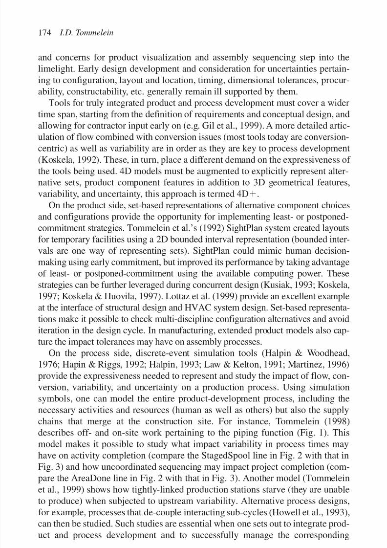
7/14/2019 4DCAD and Visualization in Construction
http://slidepdf.com/reader/full/4dcad-and-visualization-in-construction-56327c6a084e9 183/296
and concerns for product visualization and assembly sequencing step into thelimelight. Early design development and consideration for uncertainties pertain-ing to configuration, layout and location, timing, dimensional tolerances, procur-
ability, constructability, etc. generally remain ill supported by them.Tools for truly integrated product and process development must cover a widertime span, starting from the definition of requirements and conceptual design, andallowing for contractor input early on (e.g. Gil et al., 1999). A more detailed artic-ulation of flow combined with conversion issues (most tools today are conversion-centric) as well as variability are in order as they are key to process development(Koskela, 1992). These, in turn, place a different demand on the expressiveness of the tools being used. 4D models must be augmented to explicitly represent alter-native sets, product component features in addition to 3D geometrical features,variability, and uncertainty, this approach is termed 4Dϩ.
On the product side, set-based representations of alternative component choicesand configurations provide the opportunity for implementing least- or postponed-commitment strategies. Tommelein et al.’s (1992) SightPlan system created layoutsfor temporary facilities using a 2D bounded interval representation (bounded inter-vals are one way of representing sets). SightPlan could mimic human decision-making using early commitment, but improved its performance by taking advantageof least- or postponed-commitment using the available computing power. These
strategies can be further leveraged during concurrent design (Kusiak, 1993; Koskela,1997; Koskela & Huovila, 1997). Lottaz et al. (1999) provide an excellent exampleat the interface of structural design and HVAC system design. Set-based representa-tions make it possible to check multi-discipline configuration alternatives and avoiditeration in the design cycle. In manufacturing, extended product models also cap-ture the impact tolerances may have on assembly processes.
On the process side, discrete-event simulation tools (Halpin & Woodhead,1976; Hapin & Riggs, 1992; Halpin, 1993; Law & Kelton, 1991; Martinez, 1996)
provide the expressiveness needed to represent and study the impact of flow, con-version, variability, and uncertainty on a production process. Using simulationsymbols, one can model the entire product-development process, including thenecessary activities and resources (human as well as others) but also the supplychains that merge at the construction site. For instance, Tommelein (1998)describes off- and on-site work pertaining to the piping function (Fig. 1). Thismodel makes it possible to study what impact variability in process times mayhave on activity completion (compare the StagedSpool line in Fig. 2 with that in
Fig. 3) and how uncoordinated sequencing may impact project completion (com-pare the AreaDone line in Fig. 2 with that in Fig. 3). Another model (Tommeleinet al., 1999) shows how tightly-linked production stations starve (they are unableto produce) when subjected to upstream variability. Alternative process designs,for example, processes that de-couple interacting sub-cycles (Howell et al., 1993),can then be studied. Such studies are essential when one sets out to integrate prod-uct and process development and to successfully manage the corresponding
174 I.D. Tommelein

7/14/2019 4DCAD and Visualization in Construction
http://slidepdf.com/reader/full/4dcad-and-visualization-in-construction-56327c6a084e9 184/296
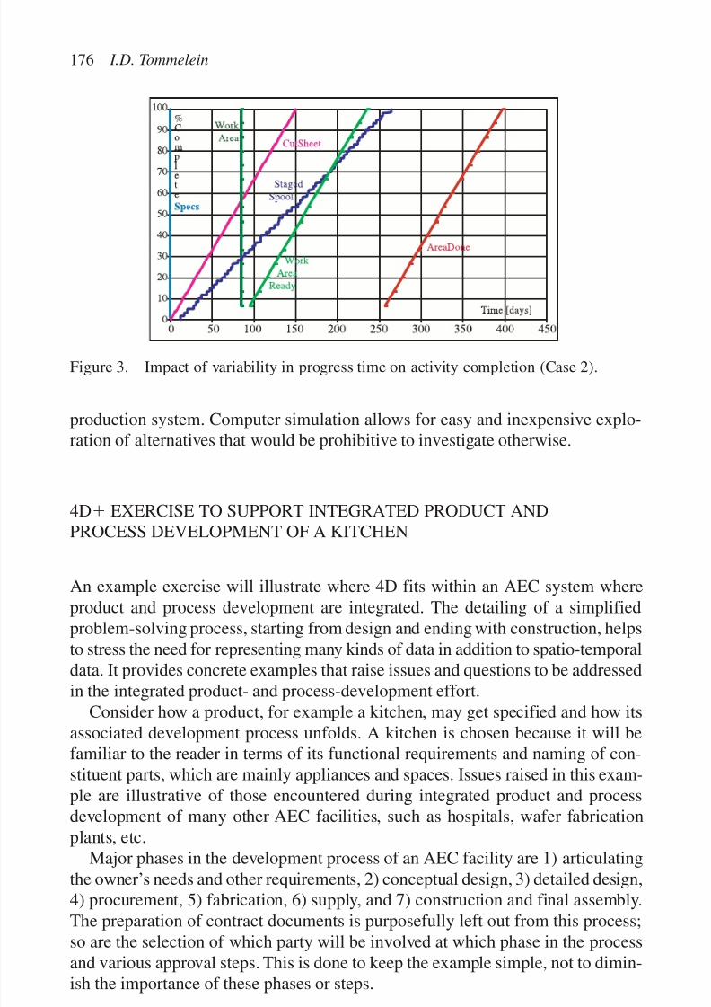
7/14/2019 4DCAD and Visualization in Construction
http://slidepdf.com/reader/full/4dcad-and-visualization-in-construction-56327c6a084e9 185/296
production system. Computer simulation allows for easy and inexpensive explo-ration of alternatives that would be prohibitive to investigate otherwise.
4Dϩ
EXERCISE TO SUPPORT INTEGRATED PRODUCT ANDPROCESS DEVELOPMENT OF A KITCHEN
An example exercise will illustrate where 4D fits within an AEC system whereproduct and process development are integrated. The detailing of a simplifiedproblem-solving process, starting from design and ending with construction, helpsto stress the need for representing many kinds of data in addition to spatio-temporaldata. It provides concrete examples that raise issues and questions to be addressed
in the integrated product- and process-development effort.Consider how a product, for example a kitchen, may get specified and how its
associated development process unfolds. A kitchen is chosen because it will befamiliar to the reader in terms of its functional requirements and naming of con-stituent parts, which are mainly appliances and spaces. Issues raised in this exam-ple are illustrative of those encountered during integrated product and processdevelopment of many other AEC facilities, such as hospitals, wafer fabricationplants, etc.
Major phases in the development process of an AEC facility are 1) articulatingthe owner’s needs and other requirements, 2) conceptual design, 3) detailed design,4) procurement, 5) fabrication, 6) supply, and 7) construction and final assembly.The preparation of contract documents is purposefully left out from this process;so are the selection of which party will be involved at which phase in the processand various approval steps. This is done to keep the example simple, not to dimin-ish the importance of these phases or steps.
176 I.D. Tommelein
Figure 3. Impact of variability in progress time on activity completion (Case 2).
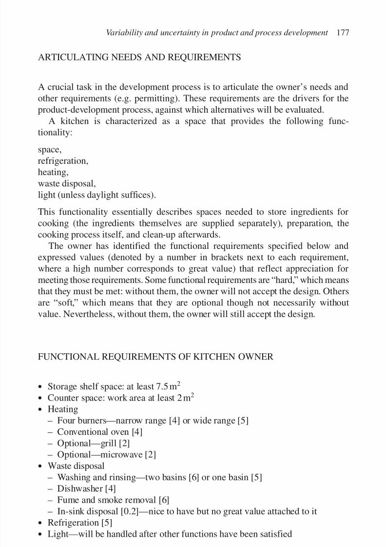
7/14/2019 4DCAD and Visualization in Construction
http://slidepdf.com/reader/full/4dcad-and-visualization-in-construction-56327c6a084e9 186/296
ARTICULATING NEEDS AND REQUIREMENTS
A crucial task in the development process is to articulate the owner’s needs andother requirements (e.g. permitting). These requirements are the drivers for theproduct-development process, against which alternatives will be evaluated.
A kitchen is characterized as a space that provides the following func-tionality:
space,refrigeration,heating,
waste disposal,light (unless daylight suffices).
This functionality essentially describes spaces needed to store ingredients forcooking (the ingredients themselves are supplied separately), preparation, thecooking process itself, and clean-up afterwards.
The owner has identified the functional requirements specified below andexpressed values (denoted by a number in brackets next to each requirement,where a high number corresponds to great value) that reflect appreciation for
meeting those requirements. Some functional requirements are “hard,” which meansthat they must be met: without them, the owner will not accept the design. Othersare “soft,” which means that they are optional though not necessarily withoutvalue. Nevertheless, without them, the owner will still accept the design.
FUNCTIONAL REQUIREMENTS OF KITCHEN OWNER
• Storage shelf space: at least 7.5 m2
• Counter space: work area at least 2 m2
• Heating– Four burners—narrow range [4] or wide range [5]– Conventional oven [4]– Optional—grill [2]– Optional—microwave [2]
• Waste disposal– Washing and rinsing—two basins [6] or one basin [5]– Dishwasher [4]– Fume and smoke removal [6]– In-sink disposal [0.2]—nice to have but no great value attached to it
• Refrigeration [5]
• Light—will be handled after other functions have been satisfied
Variability and uncertainty in product and process development 177
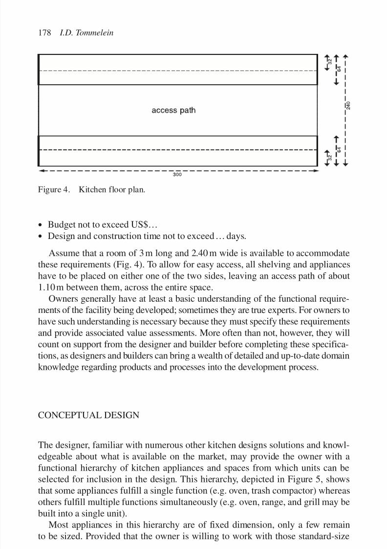
7/14/2019 4DCAD and Visualization in Construction
http://slidepdf.com/reader/full/4dcad-and-visualization-in-construction-56327c6a084e9 187/296
• Budget not to exceed US$…
• Design and construction time not to exceed… days.
Assume that a room of 3 m long and 2.40 m wide is available to accommodatethese requirements (Fig. 4). To allow for easy access, all shelving and applianceshave to be placed on either one of the two sides, leaving an access path of about
1.10m between them, across the entire space.Owners generally have at least a basic understanding of the functional require-
ments of the facility being developed; sometimes they are true experts. For owners tohave such understanding is necessary because they must specify these requirementsand provide associated value assessments. More often than not, however, they willcount on support from the designer and builder before completing these specifica-tions, as designers and builders can bring a wealth of detailed and up-to-date domainknowledge regarding products and processes into the development process.
CONCEPTUAL DESIGN
The designer, familiar with numerous other kitchen designs solutions and knowl-edgeable about what is available on the market, may provide the owner with a
functional hierarchy of kitchen appliances and spaces from which units can beselected for inclusion in the design. This hierarchy, depicted in Figure 5, showsthat some appliances fulfill a single function (e.g. oven, trash compactor) whereasothers fulfill multiple functions simultaneously (e.g. oven, range, and grill may bebuilt into a single unit).
Most appliances in this hierarchy are of fixed dimension, only a few remainto be sized. Provided that the owner is willing to work with those standard-size
178 I.D. Tommelein
Figure 4. Kitchen floor plan.
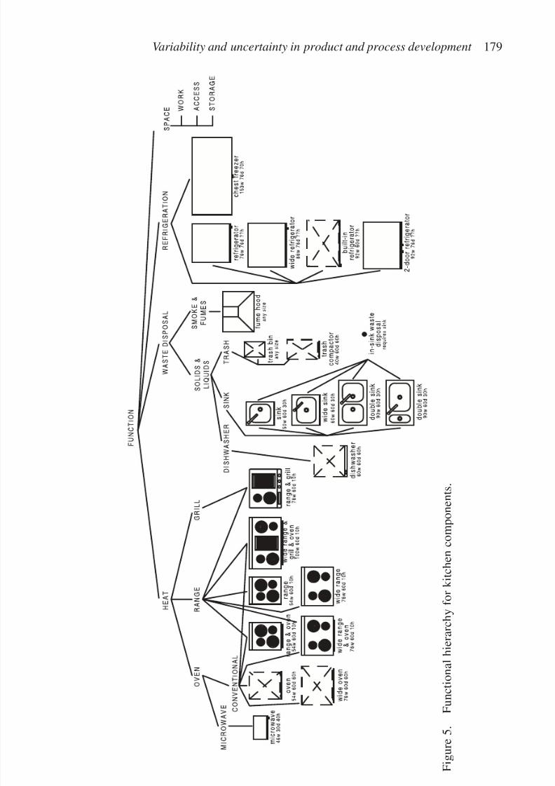
7/14/2019 4DCAD and Visualization in Construction
http://slidepdf.com/reader/full/4dcad-and-visualization-in-construction-56327c6a084e9 188/296
Variability and uncertainty in product and process development 179
F i g u r e 5 .
F u n c t i o n a l h i e r a r c h y f o r k i t c h e n c o
m p o n e n t s .
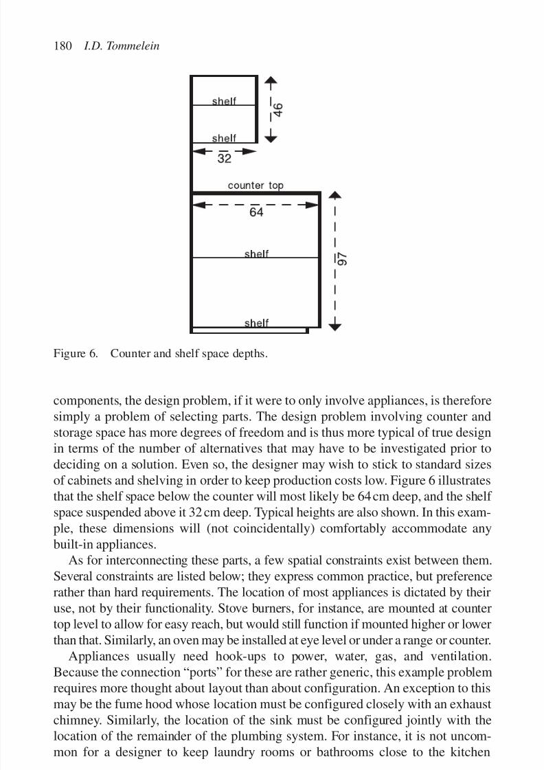
7/14/2019 4DCAD and Visualization in Construction
http://slidepdf.com/reader/full/4dcad-and-visualization-in-construction-56327c6a084e9 189/296
components, the design problem, if it were to only involve appliances, is thereforesimply a problem of selecting parts. The design problem involving counter andstorage space has more degrees of freedom and is thus more typical of true designin terms of the number of alternatives that may have to be investigated prior todeciding on a solution. Even so, the designer may wish to stick to standard sizesof cabinets and shelving in order to keep production costs low. Figure 6 illustratesthat the shelf space below the counter will most likely be 64cm deep, and the shelf space suspended above it 32 cm deep. Typical heights are also shown. In this exam-
ple, these dimensions will (not coincidentally) comfortably accommodate anybuilt-in appliances.
As for interconnecting these parts, a few spatial constraints exist between them.Several constraints are listed below; they express common practice, but preferencerather than hard requirements. The location of most appliances is dictated by theiruse, not by their functionality. Stove burners, for instance, are mounted at countertop level to allow for easy reach, but would still function if mounted higher or lowerthan that. Similarly, an oven may be installed at eye level or under a range or counter.
Appliances usually need hook-ups to power, water, gas, and ventilation.Because the connection “ports” for these are rather generic, this example problemrequires more thought about layout than about configuration. An exception to thismay be the fume hood whose location must be configured closely with an exhaustchimney. Similarly, the location of the sink must be configured jointly with thelocation of the remainder of the plumbing system. For instance, it is not uncom-mon for a designer to keep laundry rooms or bathrooms close to the kitchen
180 I.D. Tommelein
Figure 6. Counter and shelf space depths.
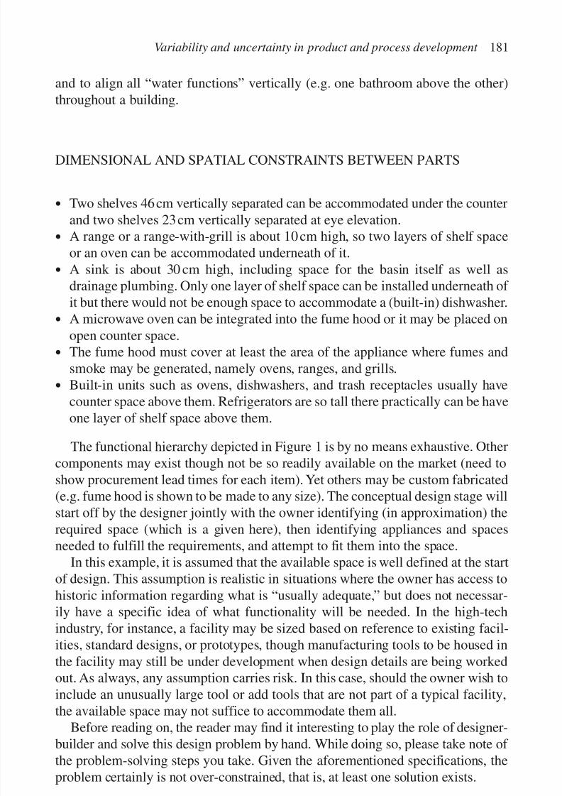
7/14/2019 4DCAD and Visualization in Construction
http://slidepdf.com/reader/full/4dcad-and-visualization-in-construction-56327c6a084e9 190/296
and to align all “water functions” vertically (e.g. one bathroom above the other)throughout a building.
DIMENSIONAL AND SPATIAL CONSTRAINTS BETWEEN PARTS
• Two shelves 46cm vertically separated can be accommodated under the counterand two shelves 23cm vertically separated at eye elevation.
• A range or a range-with-grill is about 10 cm high, so two layers of shelf spaceor an oven can be accommodated underneath of it.
• A sink is about 30 cm high, including space for the basin itself as well asdrainage plumbing. Only one layer of shelf space can be installed underneath of it but there would not be enough space to accommodate a (built-in) dishwasher.
• A microwave oven can be integrated into the fume hood or it may be placed onopen counter space.
• The fume hood must cover at least the area of the appliance where fumes andsmoke may be generated, namely ovens, ranges, and grills.
• Built-in units such as ovens, dishwashers, and trash receptacles usually havecounter space above them. Refrigerators are so tall there practically can be haveone layer of shelf space above them.
The functional hierarchy depicted in Figure 1 is by no means exhaustive. Othercomponents may exist though not be so readily available on the market (need toshow procurement lead times for each item). Yet others may be custom fabricated(e.g. fume hood is shown to be made to any size). The conceptual design stage willstart off by the designer jointly with the owner identifying (in approximation) therequired space (which is a given here), then identifying appliances and spaces
needed to fulfill the requirements, and attempt to fit them into the space.In this example, it is assumed that the available space is well defined at the start
of design. This assumption is realistic in situations where the owner has access tohistoric information regarding what is “usually adequate,” but does not necessar-ily have a specific idea of what functionality will be needed. In the high-techindustry, for instance, a facility may be sized based on reference to existing facil-ities, standard designs, or prototypes, though manufacturing tools to be housed inthe facility may still be under development when design details are being worked
out. As always, any assumption carries risk. In this case, should the owner wish toinclude an unusually large tool or add tools that are not part of a typical facility,the available space may not suffice to accommodate them all.
Before reading on, the reader may find it interesting to play the role of designer-builder and solve this design problem by hand. While doing so, please take note of the problem-solving steps you take. Given the aforementioned specifications, theproblem certainly is not over-constrained, that is, at least one solution exists.
Variability and uncertainty in product and process development 181

7/14/2019 4DCAD and Visualization in Construction
http://slidepdf.com/reader/full/4dcad-and-visualization-in-construction-56327c6a084e9 191/296
ALTERNATIVE APPROACHES FOR CONCEPTUAL DESIGN
Several methods can be followed to generate a conceptual design solution for thisproblem. Depending on the method being pursued, the solutions will be different.
Early commitment
Many designers follow a so-called early commitment approach. This approachmost likely is also the one the reader pursued. Early commitment can mean sev-eral things. The problem solver may first choose appliances one at a time from thefunctional hierarchy and try them against the functional requirements. This willeliminate the range-and-grill, for instance, as it does not provide four burners.Similarly, the requirements do not mention any trash disposal other than a sink and dishwasher, so the bin and compactor may be eliminated from considerationas well. The chest freezer is not specified either. A designer may question, how-ever, if these omissions are not an oversight on the part of the owner.
Using this method, the problem-solver may find that many appliances, whentaken individually, can meet the requirements. The next step is to fulfill eachrequirement separately and then verify if in combination they allow for sufficient
storage shelf space and counter space to remain. For instance, the range & oven,the wide-range & oven, and the wide-range & grill & oven all meet the require-ments for heating, though the first scores 8, the second 9, and the third 11.
The maximum amount of upper-shelf space Umax one could have in this kitchenis equal to the kitchen length * depth of shelf * 2 layers * 2 sides of the room or
Umax ϭ 3 m * 0.32m * 2 * 2ϭ 3.84m2
Similarly, the maximum amount of lower-shelf space Lmax one could have in this
kitchen is
Umax ϭ 3 m * 0.64m * 2 * 2ϭ 7.68m2
This yields a total shelf space of 11.52m2.The maximum amount of counter space Cmax one could have in this kitchen is
Cmax ϭ 3 m * 0.64m * 1 * 1ϭ 3.84m2
Assuming the designer chooses the option that scores the highest, the space occu-
pied by that appliance can be calculated based on an assumed position in thekitchen, and the remaining upper-shelf space, lower-shelf space, and counterspace calculated.
The next step may be to decide on means for waste disposal. Should the userproceed in this manner and for each function choose the high-end option (thelargest appliance that meets the requirements), then ultimately the space con-straints will be violated (in this particular problem). Backtracking to consider
182 I.D. Tommelein
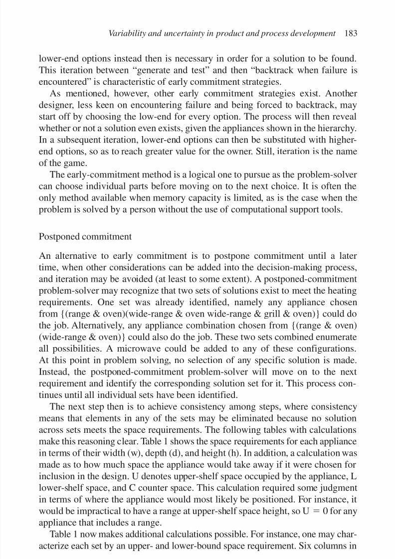
7/14/2019 4DCAD and Visualization in Construction
http://slidepdf.com/reader/full/4dcad-and-visualization-in-construction-56327c6a084e9 192/296
lower-end options instead then is necessary in order for a solution to be found.This iteration between “generate and test” and then “backtrack when failure isencountered” is characteristic of early commitment strategies.
As mentioned, however, other early commitment strategies exist. Anotherdesigner, less keen on encountering failure and being forced to backtrack, maystart off by choosing the low-end for every option. The process will then revealwhether or not a solution even exists, given the appliances shown in the hierarchy.In a subsequent iteration, lower-end options can then be substituted with higher-end options, so as to reach greater value for the owner. Still, iteration is the nameof the game.
The early-commitment method is a logical one to pursue as the problem-solvercan choose individual parts before moving on to the next choice. It is often theonly method available when memory capacity is limited, as is the case when theproblem is solved by a person without the use of computational support tools.
Postponed commitment
An alternative to early commitment is to postpone commitment until a latertime, when other considerations can be added into the decision-making process,and iteration may be avoided (at least to some extent). A postponed-commitment
problem-solver may recognize that two sets of solutions exist to meet the heatingrequirements. One set was already identified, namely any appliance chosenfrom {(range & oven)(wide-range & oven wide-range & grill & oven)} could dothe job. Alternatively, any appliance combination chosen from {(range & oven)(wide-range & oven)} could also do the job. These two sets combined enumerateall possibilities. A microwave could be added to any of these configurations.At this point in problem solving, no selection of any specific solution is made.Instead, the postponed-commitment problem-solver will move on to the next
requirement and identify the corresponding solution set for it. This process con-tinues until all individual sets have been identified.
The next step then is to achieve consistency among steps, where consistencymeans that elements in any of the sets may be eliminated because no solutionacross sets meets the space requirements. The following tables with calculationsmake this reasoning clear. Table 1 shows the space requirements for each appliancein terms of their width (w), depth (d), and height (h). In addition, a calculation wasmade as to how much space the appliance would take away if it were chosen for
inclusion in the design. U denotes upper-shelf space occupied by the appliance, Llower-shelf space, and C counter space. This calculation required some judgmentin terms of where the appliance would most likely be positioned. For instance, itwould be impractical to have a range at upper-shelf space height, so Uϭ 0 for anyappliance that includes a range.
Table 1 now makes additional calculations possible. For instance, one may char-acterize each set by an upper- and lower-bound space requirement. Six columns in
Variability and uncertainty in product and process development 183

7/14/2019 4DCAD and Visualization in Construction
http://slidepdf.com/reader/full/4dcad-and-visualization-in-construction-56327c6a084e9 193/296
Table 2 illustrate such calculations for the first heating set from {(range &oven)(wide-range & oven)(wide-range & grill & oven)}. This calculation revealsthat the lower-end choices leave sufficient space, whereas the higher-end choicesdo not. Further investigation will reveal what set combinations yield acceptablespace use and example calculations are shown in the right-most nine columns of Table 2. Only the last three of these columns present sets of appliances that in any
combination yield a solution.Admittedly, calculations like these are tedious to perform but this is exactly
where computers are most useful. They can perform calculations and keep track of sets, and thereby enable people to focus on other decision-making steps. Note thatin this example, the alternative possible configurations can be enumerated by handshould the designer wish to do so. In more complex design cases this will certainlynot be the case.
DISCUSSION
The advantage of the postponed-commitment method is that it keeps track of allpossible configurations that meet the requirements. No solutions are prematurelyrejected. While applying postponed commitment to define the product, the designer-builder should also consider production process issues, such as procurement(e.g. availability and lead times), fabrication, supply, and construction and final
184 I.D. Tommelein
Table 1. Space requirements for appliances in functional hierarchy.
w d h U L C[m] [m] [m] [m2] [m2] [m2]
Microwave 0.46 0.30 0.40 0.32 0.32Conventional oven 0.54 0.6 0.6 0 0.742 0Wide conventional oven 0.76 0.6 0.6 0 1.024 0Range & oven 0.54 0.6 0.9 0 0.742 0.371Wide-range & oven 0.76 0.6 0.9 0 1.024 0.512Wide-range & grill & oven 1 0.6 0.9 0 1.331 0.666Range 0.54 0.6 0.1 0 0 0.371Wide-range 0.76 0.6 0.1 0 0 0.512Range & grill 0.76 0.6 0.1 0 0 0.512
Dishwasher 0.6 0.6 0.6 0 0.819 0Sink 0.5 0.6 0.3 0 0.346 0.346Wide sink 0.6 0.6 0.3 0 0.41 0.41Double sink A 0.9 0.6 0.3 0 0.602 0.602Double sink B 0.9 0.6 0.3 0 0.602 0.602Refrigerator 0.72 0.76 1.64 0.2432 0.973 0.486Wide refrigerator 0.82 0.76 1.64 0.2752 1.101 0.55Two-door refrigerator 0.92 0.76 1.64 0.3072 1.229 0.614
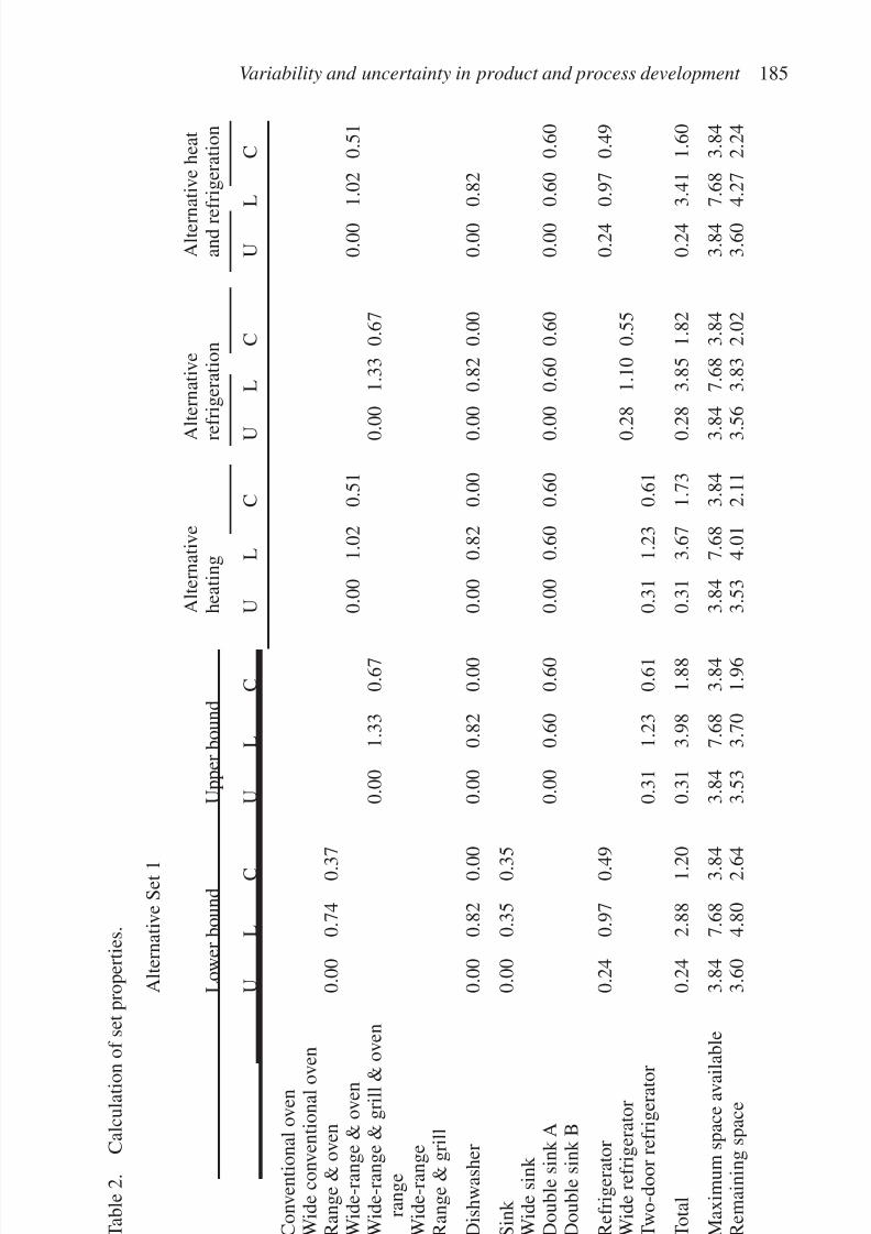
7/14/2019 4DCAD and Visualization in Construction
http://slidepdf.com/reader/full/4dcad-and-visualization-in-construction-56327c6a084e9 194/296
Variability and uncertainty in product and process development 185
T a b l e 2 .
C a l c u l a t i o n o f s e t p r o p e r t i e s .
A l t e r n a t i v e S e t 1
A l t e r n a t i v e
A l t e r n a t i v e
A l t e r n
a t i v e h e a t
L o w e r b o u n d
U p p e r b o u n d
h e a t i n g
r e f
r i g e r a t i o n
a n d r e f r i g e r a t i o n
U
L
C
U
L
C
U
L
C
U
L
C
U
L
C
C o n v e n t i o n a l o v e n
W i d e c o n v e n t i o n a l o v e
n
R a n g e & o v e n
0 . 0 0
0 . 7 4
0 . 3 7
W i d e - r a n g e & o v e n
0 . 0 0
1 . 0 2
0 . 5 1
0 . 0 0
1 . 0 2
0 . 5 1
W i d e - r a n g e & g r i l l & o v e n
0 . 0 0
1 . 3 3
0 . 6 7
0 . 0
0
1 . 3 3 0 . 6 7
r a n g e
W i d e - r a n g e
R a n g e & g r i l l
D i s h w a s h e r
0 . 0 0
0 . 8 2
0 . 0 0
0 . 0 0
0 . 8 2
0 . 0 0
0 . 0 0
0 . 8 2
0 . 0 0
0 . 0
0
0 . 8 2 0 . 0 0
0 . 0 0
0 . 8 2
S i n k
0 . 0 0
0 . 3 5
0 . 3 5
W i d e s i n k
D o u b l e s i n k A
0 . 0 0
0 . 6 0
0 . 6 0
0 . 0 0
0 . 6 0
0 . 6 0
0 . 0
0
0 . 6 0 0 . 6 0
0 . 0 0
0 . 6 0
0 . 6 0
D o u b l e s i n k B
R e f r i g e r a t o r
0 . 2 4
0 . 9 7
0 . 4 9
0 . 2 4
0 . 9 7
0 . 4 9
W i d e r e f r i g e r a t o r
0 . 2
8
1 . 1 0 0 . 5 5
T w o - d o o r r e f r i g e r a t o r
0 . 3 1
1 . 2 3
0 . 6 1
0 . 3 1
1 . 2 3
0 . 6 1
T o t a l
0 . 2 4
2 . 8 8
1 . 2 0
0 . 3 1
3 . 9 8
1 . 8 8
0 . 3 1
3 . 6 7
1 . 7 3
0 . 2
8
3 . 8 5 1 . 8 2
0 . 2 4
3 . 4 1
1 . 6 0
M a x i m u m s p a c e a v a i l a
b l e
3 . 8 4
7 . 6 8
3 . 8 4
3 . 8 4
7 . 6 8
3 . 8 4
3 . 8 4
7 . 6 8
3 . 8 4
3 . 8
4
7 . 6 8 3 . 8 4
3 . 8 4
7 . 6 8
3 . 8 4
R e m a i n i n g s p a c e
3 . 6 0
4 . 8 0
2 . 6 4
3 . 5 3
3 . 7 0
1 . 9 6
3 . 5 3
4 . 0 1
2 . 1 1
3 . 5
6
3 . 8 3 2 . 0 2
3 . 6 0
4 . 2 7
2 . 2 4
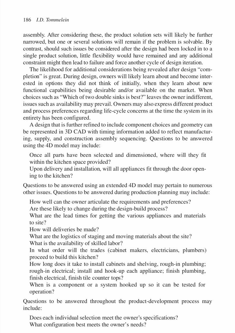
7/14/2019 4DCAD and Visualization in Construction
http://slidepdf.com/reader/full/4dcad-and-visualization-in-construction-56327c6a084e9 195/296
assembly. After considering these, the product solution sets will likely be furthernarrowed, but one or several solutions will remain if the problem is solvable. Bycontrast, should such issues be considered after the design had been locked in to a
single product solution, little flexibility would have remained and any additionalconstraint might then lead to failure and force another cycle of design iteration.The likelihood for additional considerations being revealed after design “com-
pletion” is great. During design, owners will likely learn about and become inter-ested in options they did not think of initially, when they learn about newfunctional capabilities being desirable and/or available on the market. Whenchoices such as “Which of two double sinks is best?” leaves the owner indifferent,issues such as availability may prevail. Owners may also express different productand process preferences regarding life-cycle concerns at the time the system in itsentirety has been configured.
A design that is further refined to include component choices and geometry canbe represented in 3D CAD with timing information added to reflect manufactur-ing, supply, and construction assembly sequencing. Questions to be answeredusing the 4D model may include:
Once all parts have been selected and dimensioned, where will they fitwithin the kitchen space provided?Upon delivery and installation, will all appliances fit through the door open-ing to the kitchen?
Questions to be answered using an extended 4D model may pertain to numerousother issues. Questions to be answered during production planning may include:
How well can the owner articulate the requirements and preferences?Are these likely to change during the design-build process?What are the lead times for getting the various appliances and materialsto site?
How will deliveries be made?What are the logistics of staging and moving materials about the site?What is the availability of skilled labor?In what order will the trades (cabinet makers, electricians, plumbers)proceed to build this kitchen?How long does it take to install cabinets and shelving, rough-in plumbing;rough-in electrical; install and hook-up each appliance; finish plumbing,finish electrical, finish tile counter tops?
When is a component or a system hooked up so it can be tested foroperation?
Questions to be answered throughout the product-development process mayinclude:
Does each individual selection meet the owner’s specifications?What configuration best meets the owner’s needs?
186 I.D. Tommelein

7/14/2019 4DCAD and Visualization in Construction
http://slidepdf.com/reader/full/4dcad-and-visualization-in-construction-56327c6a084e9 196/296
The set-based representation, like the one presented here to extend the usefulnessof 4D models, enables AEC practitioners to consider alternatives in productswhile taking process issues into account. It not only yields better solutions, but
also avoids needless iteration. Other industries have adopted this approach (e.g.Ward et al., 1995; Sobek et al., 1999).
CONCLUSIONS
This study has presented sources of variability and uncertainty in product as well asprocess definition. A world in which no variation or uncertainty is recognized typi-cally gets modeled by means of single numbers, often representing expected values.These values are mathematically speaking most likely to occur but in reality have analmost zero likelihood of actually occurring. Singe values reflecting early commit-ment tend to lead to process iteration. Systems that are subject to variability anduncertainty in terms of processing times exhibit phenomena such as “starvation”that lead to detrimental performance. Models based on averages are unrealisticallyoptimistic. Systems that are based on unique selections at each design step, tend tocause substantial iteration and rework when conflicts are detected. This chapter has
therefore argued for the creation and study of 4D models that explicitly representvariability and uncertainty as well as sets of alternatives, referred to as 4Dϩ.Examples illustrated how 4Dϩ representations make it possible to better managethe production system that supports integrated product and process development.
People’s ability and ease with which they can solve problems depends on therepresentation that is being used. Researchers and practitioners need to expandtheir conceptualizations of AEC systems so as to allow for integrated product andprocess development, and then develop representations and problem-solving
methods to enable us to really tackle the problems face.
ACKNOWLEDGMENTS
Several ideas presented in this chapter were refined during much-valued discussionswith Glenn Ballard, Carlos Formoso, Hyun Jeong Choo, Marcelo Sadonio, Nuno
Gil, Cynthia Tsao, Jan Elfving, Nadia Akel, Michael Whelton, and Yong-WooKim. Research leading to the development of CADSaPPlan was funded by grantCMS-9622308 from the National Science Foundation (NSF). On-going researchon integrated product and process development is being funded by grant SBR-9811052 from NSF. All support is gratefully acknowledged. Any opinions, find-ings, conclusions, or recommendations expressed in this chapter are those of theauthor and do not necessarily reflect the views of NSF.
Variability and uncertainty in product and process development 187

7/14/2019 4DCAD and Visualization in Construction
http://slidepdf.com/reader/full/4dcad-and-visualization-in-construction-56327c6a084e9 197/296
REFERENCES
Aalami, F.B. 1998. Using construction method models to generate four-dimensional
production models. Ph.D. Dissertation, Department of Civil and EnvironmentalEngineering, Stanford University, CA.
Akinci, B., Fischer, M. & Zabelle, T. 1998. Proactive approach for reducing non-valueadding activities due to time–space conflicts. Proceedings of the 6th annual conferenceof the International Group for Lean Construction (IGLC-6): Guaruja, Brazil, August:12 pp., available at http://www.ce.berkeley.edu/ ϳtommelein/IGLC-6/
Allen, J.F. 1984. Towards a general theory of action and time. Artificial Intelligence 23:123–154.
Balkany, A., Birmingham, W.P. & Tommelein, I.D. 1993. An analysis of several designsystems. Journal of Artificial Intelligence in Engineering, Design, and Manufacturing7(1): 1–17. AI EDAM.
Ballard, G. & Howell, G. 1998. Shielding production: essential step in production control. Journal of Construction Engineering and Management 124(1): 11–17. ASCE.
Clancey, W.J. 1985. Heuristic classification: 68 pp. Knowledge Systems LaboratoryReport Nr. KSL-85-5, Stanford University.
Crichton, C. 1966. Interdependence and uncertainty. A study of the building industry: 83pp. London: Tavistock Pubs., Tavistock Institute.
Durfee, E.H. 1988. Coordination of distributed problem solvers. Kluwer Academic Pubs.Dzeng, R.-J. 1995. CasePlan: a case-based planner and scheduler for construction using
product modeling. Ph.D. Dissertation, Department of Civil and EnvironmentalEngineering, University of Michigan, Ann Arbor, MI, September, 300 pp. (also ReportNo. UMCEE 95–22).
Dzeng, R.-J. & Tommelein, I.D. 1993. Using product models to plan construction.Proceedings of the 5th international conference on computing in civil and buildingengineering, Anaheim, Calif., 7–9 June: 1778–1785. ASCE.
Forrester, J.W. 1961. Industrial dynamics. M.I.T. Press.Gil, N., Tommelein, I.D., Miles, R.S., Ballard, G. & Kirkendall, R.L. 1999. Integrated
product–process development model to support design-build. In M. Hannus,M. Salonen & A.S. Kazi (eds), Concurrent engineering in construction: challenges for
the new millenium: 367–376. CIB Publication 236. Proceedings of the 2nd internationalconference on concurrent engineering in construction (CEC 99), Espoo, Finland, 25–27 August. Organized by CIB TG33 and VTT Building Technology.
Halpin, D.W. 1993. Process-based research to meet the international challenge. Journal of Construction Engineering and Management 119(3): 417–425. ASCE.
Halpin, D.W. & Riggs, L.S. 1992. Planning and analysis of construction operations: 381pp. New York: Wiley-Interscience.
Halpin, D.W. & Woodhead, R.W. 1976. Design of construction and process operations.New York: John Wiley and Sons.
Harris, R.B. & Ioannou, P.G. 1998. Scheduling projects with repeating activities. Journal
of Construction Engineering and Management 124(4): 269–278. ASCE.Hayes-Roth, B. 1985. A blackboard architecture for control. Artificial Intelligence 26:
251–321.Hayes-Roth, B., Garvey, A., Johnson, M.V., Jr. & Hewett, M. 1987. A modular and
layered environment for reasoning about action. Report No. KSL-86-38, 63 pp.Knowledge Systems Lab., Computer Science Department, Stanford University, CA,April.
188 I.D. Tommelein

7/14/2019 4DCAD and Visualization in Construction
http://slidepdf.com/reader/full/4dcad-and-visualization-in-construction-56327c6a084e9 198/296
Howard, H.C., Levitt, R.E., Paulson, B.C., Pohl, J.G. & Tatum, C.B. 1989. Computerintegration: reducing fragmentation in the AEC Industry. Journal of Computer and Civil Engineering 3(1): 18–32. ASCE.
Howell, G., Laufer, A. & Ballard, G. 1993. Interaction between sub-cycles: one key to
improved methods. Journal of Construction Engineering and Management 119(4):714–728. ASCE.
Issa, R.R. (ed.), Fernando, T., Naidoo, S.R. & Toledo Santos, E. (section eds) 1999. Stateof the art report virtual reality in construction. CIB TG24, January, available athttp://www.bcn.ufl.edu/tg24/final/
Koskela, L. 1992. Application of the new production philosophy to construction.Technical Report 72, 75 pp. CIFE, Stanford University, CA, September.
Koskela, L. 1997. Re-engineering, concurrent engineering, lean production: what isthe ideal antidote for the construction industry’s ailments? In S. Mohamed (ed.),Proceedings of the international conference on construction process re-engineering,Gold Coast, Griffith University, QLD, Australia, 14–15 July: 293–301.
Koskela, L. & Huovila, P. 1997. On foundations of concurrent engineering. In C. Anumba,& N. Evbuomwan (eds), Paper presented at Concurrent engineering in constructionCEC 97; 1st international conference, London, 3–4 July: 22–32. London: The Instituteof Structural Engineers.
Kusiak, A. (ed.) 1993. Concurrent engineering: automation, tools, and techniques. JohnWiley & Sons.
Law, A.M. & Kelton, W.D. 1991. Simulation modeling and analysis, 2nd edition: 759 pp.McGraw-Hill, Inc.
Levitt, R.E. 1995. Foreword. In I.D. Tommelein (ed.), Expert systems for civil engineers:integration issues: 247 pp. Expert Systems and Artificial Intelligence Committee,Technical Council on Computer Practices. ASCE.
Levitt, R.E. & Kunz, J.C. 1985. Using knowledge of construction and project managementfor automated schedule updating. Project Management Journal 16(5), December.
Lottaz, C., Clément, D.E., Faltings, B.V. & Smith, I.F.C. 1999. Constraint-based supportfor collaboration in design and construction. Journal of Computer and Civil Engineering 13(1): 23–35. ASCE.
Martinez, J.C. 1996. STROBOSCOPE state and resource based simulation of construction processes. Ph.D. Dissertation, Civil and Environmental Engineering, University of
Michigan, Ann Arbor, MI, 518 pp., available at http://www.strobos.ce.vt.edu/ Mittal, S. & Frayman, F. 1989. Towards a generic model of configuration tasks.Proceedings of the 11th IJCAI, August: 1395–1401.
Nii, H.P. 1986a. Blackboard systems: the blackboard model of problem solving and theevolution of blackboard architectures. AI Magazine 7(2): 38–53.
Nii, H.P. (1986b). Blackboard systems: blackboard application systems, blackboardsystems from a knowledge engineering perspective. AI Magazine 7(3): 82–106.
Odeh, A.M. 1992. CIPROS: Knowledge-based construction integrated project and process planning simulation system. Ph.D. Dissertation, Department of Civil andEnvironmental Engineering, University of Michigan, Ann Arbor, MI.
Revit. 2001. www.revit.comSadonio, M., Tommelein, I.D. & Zabelle, T.R. 1998. The LAST DESIGNER’S database-
CAD for sourcing, procurement, and planning. Proceedings of the Computing Congress98: 364–377. ASCE.
Simon, H.A. 1996. The sciences of the artificial, 3rd edition. Cambridge, Mass.: MIT Press.Smithers, T. 1989. AI-based design versus geometry-based design or why design cannot
be supported by geometry alone. Computer-Aided Design 21(3): 141–150.
Variability and uncertainty in product and process development 189

7/14/2019 4DCAD and Visualization in Construction
http://slidepdf.com/reader/full/4dcad-and-visualization-in-construction-56327c6a084e9 199/296
Sobeck, D.K., II, Ward, A.C. & Liker, J.K. 1999. Toyota’s principles of set-basedconcurrent engineering. Sloan Management Review Winter: 40(2): 67–88.
Stefik, M. 1995. Introduction to knowledge systems. Morgan Kaufmann Publishers.Thabet, W.Y. 1992. A space-constrained resource-constrained scheduling system for
multi-story buildings. Ph.D. Dissertation, Civil Engineering Department, VirginiaPolytechnique and State University, Blacksburg, VA, 644 pp.
Tommelein, I.D. 1989. SightPlan— An expert system that models and augments humandecision-making for designing construction site layouts. Ph.D. Dissertation,Department of Civil Engineering, Stanford University, Stanford, CA, 203 pp.
Tommelein, I.D. (ed.) 1995a. Expert systems for civil engineers: integration issues:247 pp. Expert Systems and Artificial Intelligence Committee, Technical Councilon Computer Practices, ASCE.
Tommelein, I.D. (ed.) 1995b. Introduction: knowledge-based systems and models for integration: 1–39 in Tommelin 1995a.
Tommelein, I.D. 1998. Pull-driven scheduling for pipe-spool installation: simulation of alean construction technique. Journal of Construction Engineering and Management 124(4): 279–288. ASCE.
Tommelein, I.D., Carr, R.I. & Odeh, A.M. 1994. Assembly of simulation networks usingdesigns, plans, and methods. Journal of Construction Engineering and Management 120(4): 796–815. ASCE.
Tommelein, I.D., Levitt, R.E. & Hayes-Roth, B. 1992. Site layout modeling: how canartificial intelligence help? Journal of Construction Engineering and Management 118(3): 594–611. ASCE.
Tommelein, I.D., Levitt, R.E., Hayes-Roth, B. & Confrey T. 1991. SightPlan experiments:alternative strategies for site layout design. Journal of Computer and Civil Engineering5(1): 42–63. ASCE.
Tommelein, I.D., Riley, D. & Howell, G.A. 1999. Parade game: impact of work flowvariability on trade performance. Journal of Construction Engineering and Management 125(5): 304–31. ASCE.
Tommelein, I.D. & Zouein, P.P. 1993. Interactive dynamic layout planning. Journal of Construction Engineering and Management 119(2): 266–287. ASCE.
Tsao, C.C.Y., Tommelein, I.D., Swanlund, E. & Howell, G.A. 2000. Case study for work structuring: installation of metal door frames. Proceedings of the eighth annual
conference of the International Group for Lean Construction (IGLC-8), Brighton, UK,17–19 July.
Voeller, J. 1996. Data-centered thinking. Editorial. Journal of Computer and Civil Engineering 10(1): 1–2. ASCE.
Ward, A.C., Liker, J.K., Cristiano, J.J. & Sobeck, D.K., II. 1995. The second toyotaparadox: how delaying decisions can make better cars faster. Sloan Management Review Spring: 43–61.
FURTHER READING
Alarcon, L. (ed.) 1997. Lean construction: 497 pp. Rotterdam: A.A. Balkema.Anumba, C.J. & Evbuomwan, N.F.O. 1997. Collaborative working in construction—the
need for effective communication protocols. Proceedings of the 4th congress oncomputer in civil engineering: 89–96 . ASCE.
Autodesk 1997. AutoCAD release 14. User’s guide. San Rafael, CA: Autodesk, Inc.
190 I.D. Tommelein

7/14/2019 4DCAD and Visualization in Construction
http://slidepdf.com/reader/full/4dcad-and-visualization-in-construction-56327c6a084e9 200/296
Ballard, G. & Howell, G. 1994. Improving performance behind the shield. Proceedings of the 2nd annual conference of the International Group for Lean Construction, Santiago,Chile, reproduced in Alarcon, 1997.
Bechtel. 1988. 3D design systems users manual, Overview of Bechtel 3D design system.
Version 1.1, Bechtel Power Corp., Gaithersburg, MD.Beliveau, Y.J., Williams, J.M., King, M.G. & Niles, A.R. 1995. Real-time position
measurement integrated with CAD: technologies and their protocols. Journal of Construction Engineering and Management 121(4): 346–354. ASCE.
Bernold, L.E. & Salim, Md. 1993. Placement-oriented design and delivery of concretereinforcement. Journal of Construction Engineering and Management 119(2):323–335. ASCE.
Bernold, L.E. & Treseler, J.F. 1991. Vendor analysis for best buy in construction. Journalof Construction Engineering and Management 117(4): 645–658. ASCE.
Choo, H.J. & Tommelein, I.D. 1999. Space scheduling using flow analysis. InI.D. Tommelein (ed.), Proceedings of the 7th annual conference of the InternationalGroup on Lean Construction (IGLC-7), Berkeley, CA, 26–28 July: 299–311, availableat http://www.ce.berkeley. edu/ ϳtommelein/IGLC-7/
Choo, H.J. & Tommelein, I.D. 1999. Parade of trades: a computer game for understanding variability and dependence. Technical Report 99-1, ConstructionEngineering and Management Program, Civil and Environmental EngineeringDepartment, University of California, Berkeley, September, available at http://www.ce.berkeley.edu/ ϳtommelein/parade/parade.pdf
Choo, H.J. & Tommelein, I.D. 2000. Interactive coordination of distributed work plans.
ASCE, Proceedings of the construction congress VI, Orlando, Florida, 20–22February:10 pp. (in press).CPI. 1998. Collaboration in the building process. The Collaborative Process Institute,
http://www.dprinc.com/collabor.htmlThe Economist 1999. Tomorrow’s internet. The Economist November 13: 23–26.Edlinger, P. 1997. Importance of data exchange standards for process industry. Editorial.
Journal of Computer and Civil Engineering January: 6–7. ASCE.Elzarke, H.M. & Bell, L.C. 1995. Object-oriented methodology for materials-
management systems. Journal of Construction Engineering and Management 121(4):438–445. ASCE.
Fischer, M. & Froese, T. 1996. Examples and characteristics of shared project models. Journal of Computer and Civil Engineering 10(3): 174–182. ASCE.Fisher, N. & Yin, S.L. 1992. Information management in a contractor. A model of the flow
of project data. 260 pp. London: Thomas Telford.Goldratt, E.M. & Cox, J. 1986. The goal. Croton-on-Hudson, NY: North River Press.Hammer, M. 1990. Reengineering work: don’t automate, obliterate. Harvard Business
Review July–August: 104–112.Jin, Y. & Levitt, R.E. 1996. The virtual design team: a computational model of project
organizations. Computational & Mathematical Organization Theory 2(3): 171–196.Lin, K.-L. & Haas, C.T. 1996. An interactive planning environment for critical operations.
Journal of Construction Engineering Management 122(3): 212–222. ASCE.Maxim, B., Balkany, A., Birmingham, W.P., Darr, T.P., Runkel, J.T. & Tommelein, I.D.
1992. Prototyping knowledge-based design systems in an object-oriented environment.The Society for Computer Simulation and Object Management Group. Proceedings of the international conference on object-oriented manufacturing systems, ICOOMS ’92,University of Calgary, Canada, 4–6 May: 55–59.
Oglesby, C.H., Parker, H.W. & Howell, G.A. 1989. Productivity improvement inconstruction. New York: McGraw-Hill Inc.
Variability and uncertainty in product and process development 191
7/14/2019 4DCAD and Visualization in Construction
http://slidepdf.com/reader/full/4dcad-and-visualization-in-construction-56327c6a084e9 201/296
Proof. 1995. Using proof animation, 2nd edition. Annandale, VA: Wolverine SoftwareCorp.
Riley, D.R. 1994. Modeling the space behavior of construction activities. Ph.D.Dissertation, Department of Architectural Engineering, Pennsylvania State University,
University Park, PA, 296 pp.Riley, D.R. & Sanvido, V.E. 1995. Patterns of construction-space use in multistory
buildings. Journal of Construction Engineering and Management 121(4): 464–473.ASCE.
Riley, D. & Sanvido, V. 1997. Space planning for mechanical, electrical, plumbing, andfire protection trades in multi-story building construction. In S. Anderson (ed.),Proceedings of the construction congress V, Minneapolis, MN: 102–109. ASCE.
Rojas, E.M. 1997. Developing web-centric systems for collaborative engineering.Proceedings of the 4th congress on computers in civil engineering: 232–239. ASCE.
Rother, M. & Shook, J. 1998. Learning to see: value stream mapping to create value and eliminate muda, Vol. 1.1, Oct. Brookline, Mass.: The Lean Enterprise Inst.
Schmenner, R.W. 1993. Production/operation management: from the inside out, 5thedition: 825 pp. Prentice Hall.
Schrage, M. 1997. The real problem with computers. Harvard Business ReviewSeptember–October: 178–188.
Stukhart, G. 1995. Construction materials management . Marcel Dekker, Inc.Stumpf, A.L., Ganeshan, R., Chin, S. & Liu, L. 1996. Object-oriented model for
integrating construction product and process information. Journal of Computer and Civil Engineering 10(3): 204–212. ASCE.
Tommelein, I.D. 1991. Site layout: where should it go? Proceedings of the ConstructionCongress 91: 632–637. ASCE.Tommelein, I.D. & Ballard, G. 1997a. Coordinating specialists. Technical Report No.
97-8, Construction Engineering and Management Programme, Civil and EnvironmentalEngineering Department, University of California, Berkeley, CA. Also in Proceedingsof the 2nd international seminar on lean construction, Sao Paulo, Brazil, 20–21October . Organized by A.S.I. Conte, Logical Systems, Sao Paulo, Brazil.
Tommelein, I.D. & Ballard, G. 1997b. Lookahead planning: screening and pulling.Technical Report No. 97-9, Construction Engineering and Management Programme,Civil and Environmental Engineering Department, University of California, Berkeley,
CA. Also in Proceedings of the 2nd international seminar on lean construction, SaoPaulo, Brazil, 20–21 October. Organized by A.S.I. Conte, Logical Systems, Sao Paulo,Brazil.
Tommelein, I.D., Dzeng, R.J. & Zouein, P.P. 1993. Exchanging layout and schedule datain a real-time distributed environment. Proceedings of the 5th international conferenceon computing in civil and building engineering, Anaheim, California, 7–9 June:947–954. ASCE.
VRML. 1995. The virtual reality modeling language, Version 1.0 specification. May 26,available at http://www.virtpark.com/theme/vrml/, visited 7/16/99.
Womack, J.P. & Jones, D.T. 1996. Lean thinking: banish waste and create wealth in your
corporation: 350 pp. New York: Simon & Schuster.Zabelle, T.R. & Fischer, M.A. 1999. Delivering value through the use of three-
dimensional computer modeling. CEC 99—Proceedings of the 2nd internationalconference on concurrent engineering in construction, CIB TG33 and VTT, Espoo,Finland, 25–27 August.
192 I.D. Tommelein

7/14/2019 4DCAD and Visualization in Construction
http://slidepdf.com/reader/full/4dcad-and-visualization-in-construction-56327c6a084e9 202/296
Zouein, P.P. 1995. MoveSchedule: a planning tool for scheduling space use onconstruction sites. Ph.D. Dissertation, Civil and Environmental EngineeringDepartment, University of Michigan, Ann Arbor, 308 pp.
Zouein, P.P. & Tommelein, I.D. 1999. Dynamic layout planning using a hybrid
incremental solution method. Journal of Construction Engineering and Management 125(6): 400–408. ASCE.
Zouein, P.P. & Tommelein, I.D. 2001. Improvement Algorithm for Limited SpaceScheduling. Journal of Construction Engineering and Management 127(2): 116–124.ASCE.
Variability and uncertainty in product and process development 193

7/14/2019 4DCAD and Visualization in Construction
http://slidepdf.com/reader/full/4dcad-and-visualization-in-construction-56327c6a084e9 203/296

7/14/2019 4DCAD and Visualization in Construction
http://slidepdf.com/reader/full/4dcad-and-visualization-in-construction-56327c6a084e9 204/296
APPLICATION OF 4D CAD IN THE CONSTRUCTIONWORKPLACE
Richard J. Coble1, Robert L. Blatter2, Indrid Agaj1
1 M.E. Rinker, Sr. School of Building Construction,University of Florida, Gainesville, FL, USA2Gresham Smith and Partners, Jacksonville, FL, USA
195
Abstract
4D is the new breed of CAD, which accounts for the fourth dimension, time. A 3D draw-
ing of a project is linked with the schedule forming an integrated 4D model that becomes
a powerful tool for construction managers. It is also a tool that can be used at the foreman
level. The concept of requiring foreman to equate 3D drawings with time should be thegoal of every construction manager. Time is the basis on which contracts are awarded, dis-
putes originate, and the projects success is judged. A foreman must understand the intent
and end result of a segment before it can be constructed. If the foreman can be helped
through this process with visualization tools, the issue becomes one of cost vs. value
analysis. Current computer technology is making its way into the hands of foreman
through the use of portable computers, PDAs, and wireless communications. The accept-
ance of computer technology by foreman is on the rise with many companies making it a
requirement for employment. This acceptance is what makes 4D CAD desirable for field
application in the construction industry. Presently, by the use of still photography andother information and communication media, 4D CAD usage at the foreman level can be
a reality in the near future.
Keywords: 4D CAD, construction foreman, computer applications, change order, field
applications
INTRODUCTION
The techniques utilized today in turning an owner’s need and/or idea into aphysically standing and usable structure typically involve graphing the complexconstruction process into a bar chart and/or CPM schedule. This representa-tion communicates the sequence of activities over time but does not provide a

7/14/2019 4DCAD and Visualization in Construction
http://slidepdf.com/reader/full/4dcad-and-visualization-in-construction-56327c6a084e9 205/296
relationship to the physical objects represented by those activities. Constructionmanagers, owners, and designers have to visualize the relationship of the schedulewith the actual physical product and rely on experience to make appropriate plan-
ning decisions. Visualizing the transition from a bar chart to a finished product inthe field is the hardest for the owner of the facility.
A need exists for a comprehensive tool that allows architects, engineers andcontractors to simulate and visualize construction sequences as part of aninteractive exercise. 3D graphic models are useful in visualizing spatial rela-tionships of parts of facilities/projects. Since a CAD model provides thebasis for a common language between all parties, adding time to a 3D modelcreates a visual simulation of the construction process—4D CAD. With 4D
CAD design and construction planning alternatives can be assessed realisti-cally within the context of space and time. Simultaneous modeling of tem-poral and spatial aspects of scenario can optimize and justify the consciousdecisions that jeopardize or hinder the completion of many constructionprojects. Industry and academia have been exploring this medium to betterunderstand how it can be used effectively during the planning process.
4D CAD is a tool that supports the 4D nature of engineering and construc-tion. This tool must capture and dynamically manage the interaction between
project components and resources over time, visualize these interactions andsupport real-time interaction of users with the 4D model. This tool alsoencourages the communication, approval and improvement of constructionschedules by various parties, such as construction managers, clients, design-ers, subcontractors and community members. (http://gaudi.stanford.edu/ 4D-CAD/INTRO-4DCAD.HTML)
TODAY’S INDUSTRY TRENDS
The implementation success of 4D CAD in the construction industry is greatlydependent and driven by the different trends and factors that govern this industry.These factors include:
• Percentage of work done by subcontractors.
• Large companies’ volume vs. total industry volume.
• Percentage of large companies that perform design-build work.
• Percentage of large companies that perform CM-at-risk work.• Percentage of negotiated vs. hard-bid work.
• Number of change orders and RFIs.
• CAD literacy among construction field management.
The fluctuations of these percentages, and the increase in the number of changeorders and RFIs, will mean an increase in the need of construction companies to
196 R.J. Coble et al.

7/14/2019 4DCAD and Visualization in Construction
http://slidepdf.com/reader/full/4dcad-and-visualization-in-construction-56327c6a084e9 206/296
implement and fully adopt 4D CAD. It would be expected that the 4D CAD meth-ods would be put to use by the large construction companies first. The projectsthese companies are involved with are of a size and complexity that can absorb the
initial added design costs that come with 4D CAD. Furthermore, it is these com-panies that can afford further training and CAD literacy lessons for their fieldmanagers and foremen. 4D CAD applications in the construction workplace willbecome a reality for mid-size companies when the experiences of large companiesaccount for better project delivery method.
The above factors are the major force pushing for the implementation of 4DCAD in today’s efforts for minimizing time and cost at project delivery by theconstruction companies. Analyzing these factors in further detail will providemore accurate reasons why this implementation is the door to the future of projectmanagement and delivery.
SUBCONTRACTOR WORK
It is estimated that in general, subcontractors do about 80 to 85% of the work in
commercial projects. With the percentage of work subcontracted-out by the gen-eral contractors becoming higher, the amount of coordination and planning (betweenthe general contractor and the subcontractor) required to complete a project isincreasing. The high demand of coordination efforts is a compelling reason thatcalls for new and untraditional solutions to project management.
The major advantage of 4D CAD is the rate at which communication interfer-ence diminishes. The enormous coordination needed between the general contrac-tor and the subcontractor will be the reason that will initiate a widespread use of 4D CAD. The level of interaction and coordination between the general contrac-
tor and the subcontractor usually determines if a project will be delivered on time,under budget, and contractor initiated change order free. Implementation of 4DCAD will undoubtedly contribute to the lessening of these communication barri-ers, and the improvement of project schedule coordination. These, in turn, will bemajor factors in “ironing-out” the scheduling imperfections, which will eventuallylead towards a timely project delivery.
In the future, general contractors will need training in CAD software so thatthey will be able to manipulate the models and interpret how they should bedrawn. In addition, contractors will need to provide input to designers so thatthe CAD objects are drawn in a way that supports automated quantity take-offs. Finally, general contractors are likely to become the keepers of the mod-els, accepting information from the designer and parceling it out to thesubcontractors. This flow of information will continue throughout the projectas design changes are incorporated and propagated. (Fischer, et al., 1999)
4D CAD in the construction workplace 197

7/14/2019 4DCAD and Visualization in Construction
http://slidepdf.com/reader/full/4dcad-and-visualization-in-construction-56327c6a084e9 207/296
In addition, subcontractors will become more active in the early phases of the design as the architect and engineer develop the specifications andschematics that form the basis for subcontractors’ design. The subcontrac-
tors’ detailed designs will still need to be approved by the architect and engi-neer through the shop drawing process, but subcontractors will need todevelop CAD modeling capabilities to benefit from this involved process.Also, as subcontractors become more active in the design, they will becomebetter able to assist the general contractor in coordinating the work of sub-contractors throughout project delivery. (Civil Engineering, May 1999)
LARGE COMPANIES’ VOLUME VS. TOTAL INDUSTRY VOLUME
In 1997 there were a total of approximately two million contractors in the UnitedStates alone. Of these firms, only 667,089 were not self-employed. These compa-nies include “establishments primarily engaged in the construction of buildings andother structures, heavy construction (except buildings), additions, alterations, recon-struction, installation, and maintenance and repairs” (US Census Bureau). Alsoincluded are companies involved in land preparation, demolition, and construction
management. Of these, companies with 1–9 employees accounted for roughly 82%(543,753 companies) of all construction companies not self-employed. That meansthat only about 18% of construction companies with at least one employee, or justover 6% of all construction work is done by companies with 10 or more employees.In fact, only 55,645 companies, or 3% of all construction companies, employ 20 ormore people.
Construction put in place in September 1999 was estimated at US $700.1 billion.Of this, US $540.3 billion was performed within the private works sector while
US $159.8 billion was generated on public works projects. It could be assumedthat companies with more employees are doing more work. This would lead to theconclusion that only 6% of all construction companies account for a significantpercentage of construction in place.
While the medium and large firms constitute only 6% of all construction firms,these firms are doing most of the work. It is important to understand the differ-ences between these firms. Among the medium and large firms, there are only a fewreally large companies. One-third of 1% of all construction companies (5,684)
employ more than 100 people and only 77 of those companies employ more than,1,000 people. Engineering News Record (ENR) annually reports the top 400 con-tractors based on total revenues of the previous year. The top 400 contractors of 1999 range from US $78.7 million to US $9.7 billion annual revenues and mosthave at least 100 employees. The total volume produced domestically by thosecompanies in 1998 was approximately US $127 billion. The total value of con-struction in place in 1998 equaled US $665.446 billion. That means that ENR’s
198 R.J. Coble et al.
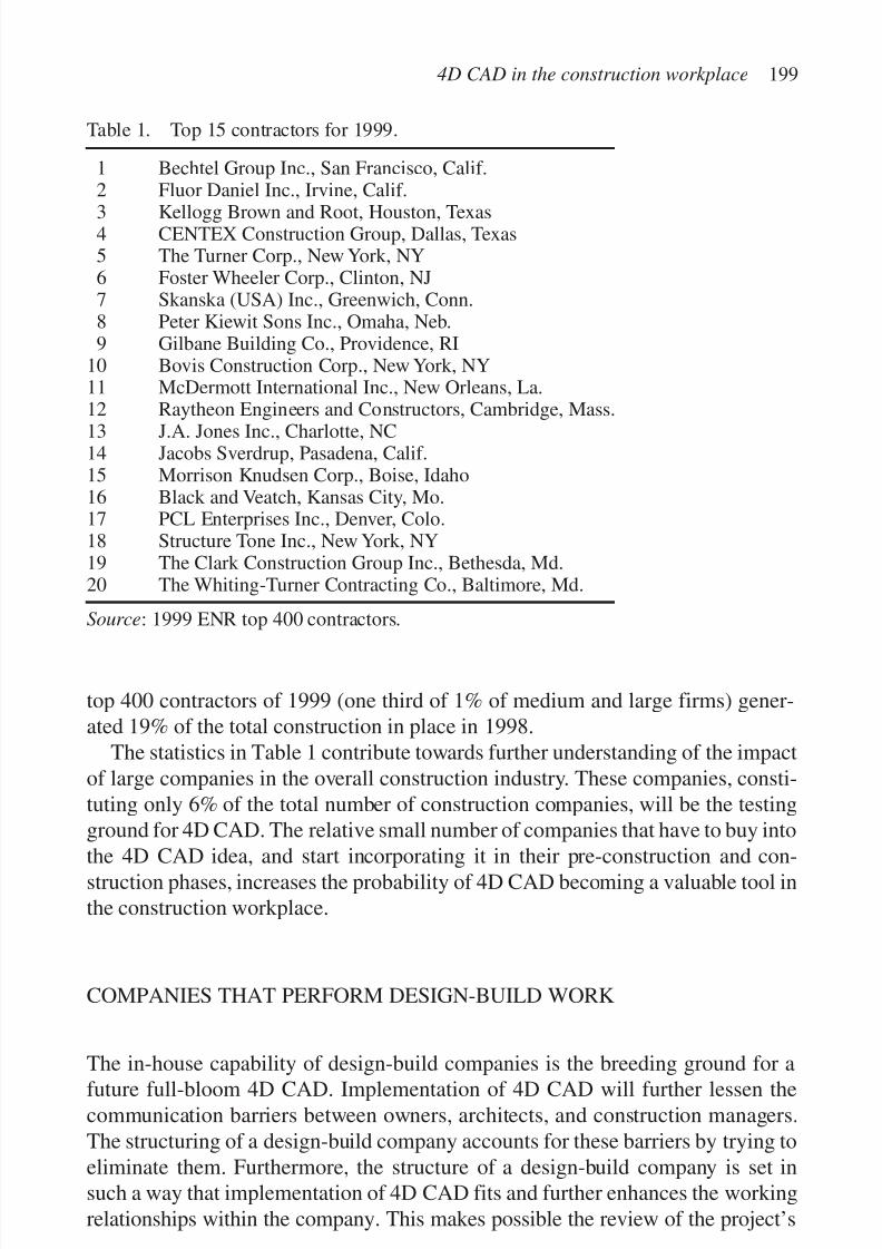
7/14/2019 4DCAD and Visualization in Construction
http://slidepdf.com/reader/full/4dcad-and-visualization-in-construction-56327c6a084e9 208/296
top 400 contractors of 1999 (one third of 1% of medium and large firms) gener-ated 19% of the total construction in place in 1998.
The statistics in Table 1 contribute towards further understanding of the impactof large companies in the overall construction industry. These companies, consti-tuting only 6% of the total number of construction companies, will be the testingground for 4D CAD. The relative small number of companies that have to buy into
the 4D CAD idea, and start incorporating it in their pre-construction and con-struction phases, increases the probability of 4D CAD becoming a valuable tool inthe construction workplace.
COMPANIES THAT PERFORM DESIGN-BUILD WORK
The in-house capability of design-build companies is the breeding ground for afuture full-bloom 4D CAD. Implementation of 4D CAD will further lessen thecommunication barriers between owners, architects, and construction managers.The structuring of a design-build company accounts for these barriers by trying toeliminate them. Furthermore, the structure of a design-build company is set insuch a way that implementation of 4D CAD fits and further enhances the workingrelationships within the company. This makes possible the review of the project’s
4D CAD in the construction workplace 199
Table 1. Top 15 contractors for 1999.
1 Bechtel Group Inc., San Francisco, Calif.2 Fluor Daniel Inc., Irvine, Calif.
3 Kellogg Brown and Root, Houston, Texas4 CENTEX Construction Group, Dallas, Texas5 The Turner Corp., New York, NY6 Foster Wheeler Corp., Clinton, NJ7 Skanska (USA) Inc., Greenwich, Conn.8 Peter Kiewit Sons Inc., Omaha, Neb.9 Gilbane Building Co., Providence, RI
10 Bovis Construction Corp., New York, NY11 McDermott International Inc., New Orleans, La.12 Raytheon Engineers and Constructors, Cambridge, Mass.
13 J.A. Jones Inc., Charlotte, NC14 Jacobs Sverdrup, Pasadena, Calif.15 Morrison Knudsen Corp., Boise, Idaho16 Black and Veatch, Kansas City, Mo.17 PCL Enterprises Inc., Denver, Colo.18 Structure Tone Inc., New York, NY19 The Clark Construction Group Inc., Bethesda, Md.20 The Whiting-Turner Contracting Co., Baltimore, Md.
Source: 1999 ENR top 400 contractors.
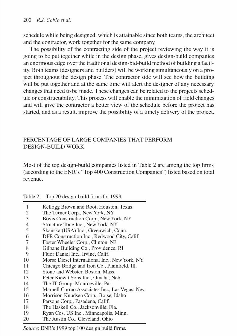
7/14/2019 4DCAD and Visualization in Construction
http://slidepdf.com/reader/full/4dcad-and-visualization-in-construction-56327c6a084e9 209/296
schedule while being designed, which is attainable since both teams, the architectand the contractor, work together for the same company.
The possibility of the contracting side of the project reviewing the way it is
going to be put together while in the design phase, gives design-build companiesan enormous edge over the traditional design-bid-build method of building a facil-ity. Both teams (designers and builders) will be working simultaneously on a pro-
ject throughout the design phase. The contractor side will see how the buildingwill be put together and at the same time will alert the designer of any necessarychanges that need to be made. These changes can be related to the projects sched-ule or constructability. This process will enable the minimization of field changesand will give the contractor a better view of the schedule before the project hasstarted, and as a result, improve the possibility of a timely delivery of the project.
PERCENTAGE OF LARGE COMPANIES THAT PERFORMDESIGN-BUILD WORK
Most of the top design-build companies listed in Table 2 are among the top firms
(according to the ENR’s “Top 400 Construction Companies”) listed based on totalrevenue.
200 R.J. Coble et al.
Table 2. Top 20 design-build firms for 1999.
1 Kellogg Brown and Root, Houston, Texas2 The Turner Corp., New York, NY3 Bovis Construction Corp., New York, NY4 Structure Tone Inc., New York, NY
5 Skanska (USA) Inc., Greenwich, Conn.6 DPR Construction Inc., Redwood City, Calif.7 Foster Wheeler Corp., Clinton, NJ8 Gilbane Building Co., Providence, RI9 Fluor Daniel Inc., Irvine, Calif.
10 Morse Diesel International Inc., New York, NY11 Chicago Bridge and Iron Co., Plainfield, Ill.12 Stone and Webster, Boston, Mass.13 Peter Kiewit Sons Inc., Omaha, Neb.14 The IT Group, Monroeville, Pa.
15 Marnell Corrao Associates Inc., Las Vegas, Nev.16 Morrison Knudsen Corp., Boise, Idaho17 Parsons Corp., Pasadena, Calif.18 The Haskell Co., Jacksonville, Fla.19 Ryan Cos. US Inc., Minneapolis, Minn.20 The Austin Co., Cleveland, Ohio
Source: ENR’s 1999 top 100 design build firms.
7/14/2019 4DCAD and Visualization in Construction
http://slidepdf.com/reader/full/4dcad-and-visualization-in-construction-56327c6a084e9 210/296
As mentioned earlier, the key in making 4D CAD a viable tool for constructionmanagement will be the initial ability of this new technique to infiltrate throughthe “old ways” of management techniques and become a popular and efficient
way of overlooking and managing a construction project.The best chance 4D CAD has in becoming the new tool in construction man-agement is to start introducing itself to the large companies first. It is these com-panies that can absorb the initial cost and adjustment that comes as a result of implementing this new technique for the first time. The nature of the projects thesecompanies are involved with provides a good ground for the testing of 4D CAD.These projects are large in size and usually innovative management techniques iswhat determines the timely and “within budget” delivery of them.
The introduction of 4D CAD in these types of projects performed by the largedesign-build companies will improve the communications among the differentlevels of parties involved in the project. The obvious result will be a betterunderstanding by the owner of how the future facility will progress through thebuilding phase. In addition, 4D CAD implementation in project delivery willfurther improve the flow of communication between the design and constructionpersonnel within the design-build company. The 4D technology will prove morebeneficial if it is implemented further on the job site by making the 4D modelavailable to the project manager, field engineer, and foreman.
When starting to analyze the numbers, the percentage of top design-build firmsthat are part of the overall top construction firms is relatively high. These compa-nies are the ones that cover most of the large project design-build work in thecountry. For 4D CAD this means that only a small percentage of the design-buildcompanies have to implement it in their system of project design and manage-ment. This relative small percentage of companies will be the testing ground forthe new tool, but at the same time this small percentage accounts for most of thelarge design-build projects currently being built. This way the 4D CAD imple-
mentation will be realistically an attainable goal, since only a relatively smallnumber of companies that will use it will cover the majority of the testing ground(the large design-build projects).
COMPANIES THAT PERFORM CM-AT-RISK WORK
The sixth largest firm in 1999 was Foster Wheeler Corporation of Clinton, New
Jersey, producing US $3.072 billion in revenue. Nearly 72% (US $2.204 billion)of its revenues were generated abroad. Foster Wheeler is another company thatspecializes in industrial projects. They completed 79 industrial projects in 1998.Of those, 38% were performed CM-at-risk. Industries served by Foster Wheelerinclude oil and gas field development, chemicals, petrochemicals and polymers,pharmaceuticals and fine chemicals, petroleum processing, power generation,cogeneration, and resource recovery.
4D CAD in the construction workplace 201
7/14/2019 4DCAD and Visualization in Construction
http://slidepdf.com/reader/full/4dcad-and-visualization-in-construction-56327c6a084e9 211/296
The Turner Corporation of New York, New York, ranked fifth with revenues of US $3.699 billion. It performed US $54.3 million of construction internationally.Turner completed 100 buildings in 1998. Its expertise is strictly in buildings, be
it pre-construction, construction management, or general contracting. Unlike othergiants in the industry, which perform relatively small amounts of constructionunder CM-at-risk contracts, Turner performed 71% of its 1998 revenues as aCM-at-risk.
Gilbane Building Company of Providence, Rhode Island, ranks ninth and earnedUS $2.248 billion. All revenues were domestic. Of this work, 51% was performedCM-at-risk. This company is involved in all major construction and real estate mar-kets: industrial, institutional, and commercial. This includes education, criminal
justice, healthcare, public assembly, aviation, life sciences, corporate, government/ public service, library, and infrastructure.
At number 10, Bovis Inc of New York, New York, earned US $2.213 billion in1998. Although Bovis is an international firm, New York, is their base of opera-tions in the United States. That means 100% of those revenues were in the UnitedStates. Bovis provides the following services: construction management, design/ build, project management, general contracting, build/operate/transfer, and systems/ consulting. Of those services, work performed CM-at-risk accounts for 87%. Thetypes of projects built include shops, offices, factories, schools, hospitals, airports,
arenas, and theaters.A glimpse at CM-at-risk operations may lend some insight. Two of the top
10—Turner and Bovis—obtain more than two-thirds of their revenues throughCM-at-risk. These firms are earning around nine times the industry average peremployee while the others are only doubling.
All the above statistics help in better understanding the role of the top build-ing firms in today’s construction industry. It is this small percentage that per-forms a large portion of the total construction volume in this country. The
volume of business these companies cover is the perfect stage for the new 4DCAD because it requires testing only on a small number of companies. Thesefirms are able to accommodate the new methods without feeling the cost of theinitial expenses.
When comparing Table 1 with Table 3, among these top firms, most of themperform a sizable portion of their work as CM-at-risk. Managing projects as aCM-at-risk company means that the actual work has to be subcontracted away.This is when 4D CAD proves to be a most valuable tool. The extensive amount of
coordination needed in such a project more than justifies the use of 4D CAD. If the CM firm has complete 4D models than they can make them available to themajor subs involved in the project. This will require full willingness to cooperatefrom the subs, but these large firms can outline that as one of the items in the con-tract between them and the subcontractors. The use of 4D CAD than will greatlyreduce of amount of miscommunication among the parties, which will in turnproduce a timely delivery of the project.
202 R.J. Coble et al.
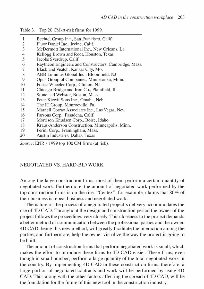
7/14/2019 4DCAD and Visualization in Construction
http://slidepdf.com/reader/full/4dcad-and-visualization-in-construction-56327c6a084e9 212/296
NEGOTIATED VS. HARD-BID WORK
Among the large construction firms, most of them perform a certain quantity of negotiated work. Furthermore, the amount of negotiated work performed by thetop construction firms is on the rise. “Centex”, for example, claims that 80% of
their business is repeat business and negotiated work.The nature of the process of a negotiated project’s delivery accommodates the
use of 4D CAD. Throughout the design and construction period the owner of theproject follows the proceedings very closely. This closeness to the project demandsa better method of communication between the professional parties and the owner.4D CAD, being this new method, will greatly facilitate the interaction among theparties, and furthermore, help the owner visualize the way the project is going tobe built.
The amount of construction firms that perform negotiated work is small, whichmakes the effort to introduce these firms to 4D CAD easier. These firms, eventhough in small number, perform a large quantity of the total negotiated work inthe country. By implementing 4D CAD in these construction firms, therefore, alarge portion of negotiated contracts and work will be performed by using 4DCAD. This, along with the other factors affecting the spread of 4D CAD, will bethe foundation for the future of this new tool in the construction industry.
4D CAD in the construction workplace 203
Table 3. Top 20 CM-at-risk firms for 1999.
1 Bechtel Group Inc., San Francisco, Calif.2 Fluor Daniel Inc., Irvine, Calif.
3 McDermott International Inc., New Orleans, La.4 Kellogg Brown and Root, Houston, Texas5 Jacobs Sverdrup, Calif.6 Raytheon Engineers and Constructors, Cambridge, Mass.7 Black and Veatch, Kansas City, Mo.8 ABB Lummus Global Inc., Bloomfield, NJ9 Opus Group of Companies, Minnetonka, Minn.
10 Foster Wheeler Corp., Clinton, NJ11 Chicago Bridge and Iron Co., Plainfield, Ill.12 Stone and Webster, Boston, Mass.
13 Peter Kiewit Sons Inc., Omaha, Neb.14 The IT Group, Monroeville, Pa.15 Marnell Corrao Associates Inc., Las Vegas, Nev.16 Parsons Corp., Pasadena, Calif.17 Morrison Knudsen Corp., Boise, Idaho18 Kraus-Anderson Construction, Minneapolis, Minn.19 Perini Corp., Framingham, Mass.20 Austin Industries, Dallas, Texas
Source: ENR’s 1999 top 100 CM firms (at risk).

7/14/2019 4DCAD and Visualization in Construction
http://slidepdf.com/reader/full/4dcad-and-visualization-in-construction-56327c6a084e9 213/296
4D CAD AND CHANGE ORDER DOCUMENTATION
4D CAD is an ideal way to document changes in job site conditions. In the follow-ing section of this paper is shown how actual job photographs can be integrated toaccomplish a clear and accurate picture of what has occurred to necessitate achange. Additionally, a clear representation is depicted as to the depth and breadthof the change.
By having this clear representation, produced in four dimensions, conflict res-olution is taken from the initial cause to an analysis of cost and process. Using thismethodology, owners gain an understanding of why their projects cost more andtake longer to complete. At the same time, designers can decipher the cause of the
conflict and how the resolution will impact associated costs.The example presented in this paper shows clearly an error by the design team.
A lack of coordination resulted in a change that necessitated a time and cost delayto the project. This could have been a major stumbling block for the project if a 4Drepresentation had not been used to illustrate the problem and present a solution.
The programs used to create this 4D example are readily available and ideal forthe issue being discussed. This type of descriptive representation is also appropri-ate for multiple changes. Manipulating the simulation to fit actual field photo-
graphs is not a difficult process. Other areas that could be examined using this toolinclude mechanical and electrical conflicts.
Case study: Girder conflict
The space being constructed was a fitness room with an exposed ceiling structureand glass walls on two sides overlooking a nearby lake. The room was intended to
204 R.J. Coble et al.
Figure 1. Job site photo of kicker penetrating soffit and window system (not yet installed).
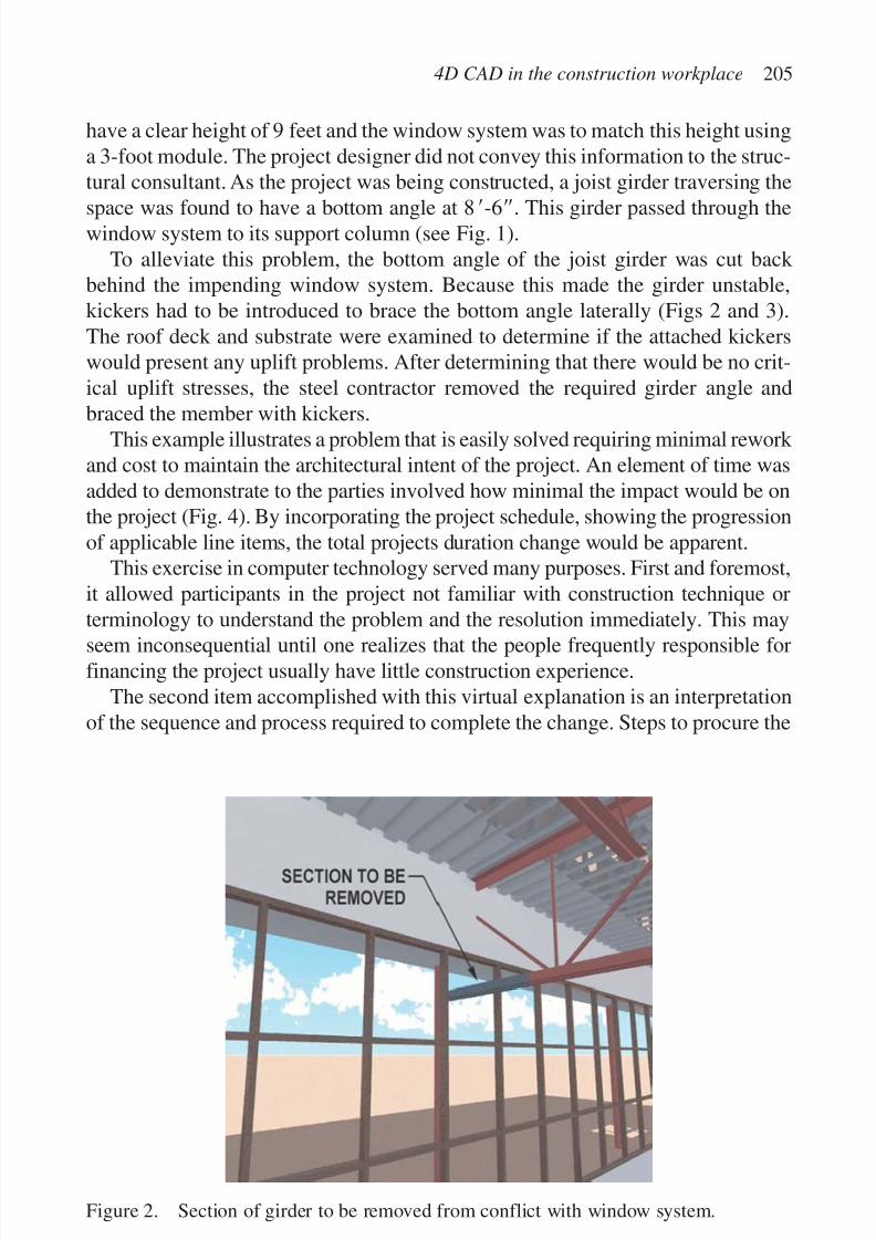
7/14/2019 4DCAD and Visualization in Construction
http://slidepdf.com/reader/full/4dcad-and-visualization-in-construction-56327c6a084e9 214/296
have a clear height of 9 feet and the window system was to match this height usinga 3-foot module. The project designer did not convey this information to the struc-tural consultant. As the project was being constructed, a joist girder traversing the
space was found to have a bottom angle at 8Ј-6ЈЈ. This girder passed through thewindow system to its support column (see Fig. 1).
To alleviate this problem, the bottom angle of the joist girder was cut back behind the impending window system. Because this made the girder unstable,kickers had to be introduced to brace the bottom angle laterally (Figs 2 and 3).The roof deck and substrate were examined to determine if the attached kickerswould present any uplift problems. After determining that there would be no crit-ical uplift stresses, the steel contractor removed the required girder angle andbraced the member with kickers.
This example illustrates a problem that is easily solved requiring minimal rework and cost to maintain the architectural intent of the project. An element of time wasadded to demonstrate to the parties involved how minimal the impact would be onthe project (Fig. 4). By incorporating the project schedule, showing the progressionof applicable line items, the total projects duration change would be apparent.
This exercise in computer technology served many purposes. First and foremost,it allowed participants in the project not familiar with construction technique orterminology to understand the problem and the resolution immediately. This may
seem inconsequential until one realizes that the people frequently responsible forfinancing the project usually have little construction experience.
The second item accomplished with this virtual explanation is an interpretationof the sequence and process required to complete the change. Steps to procure the
4D CAD in the construction workplace 205
Figure 2. Section of girder to be removed from conflict with window system.

7/14/2019 4DCAD and Visualization in Construction
http://slidepdf.com/reader/full/4dcad-and-visualization-in-construction-56327c6a084e9 215/296
206 R.J. Coble et al.
Figure 4. Project schedule outlining changes generated by girder conflict.
Figure 3. Kickers to brace girder after removal.

7/14/2019 4DCAD and Visualization in Construction
http://slidepdf.com/reader/full/4dcad-and-visualization-in-construction-56327c6a084e9 216/296
materials, schedule the labor, and install the necessary components are mapped intothe video. The project schedule associates and generates the requisite line itemsand incorporates them to produce and adjust the time scale.
TECHNOLOGY AND PROCESS
The tools and skill necessary to produce 4D CAD simulations are readily availableand require moderate training to use. Table 4 is a simplified process chart outlin-ing the applicable tools and techniques. Table 4 shows the four main componentsneeded to develop a project. Solid modeling is the component that consumes a
majority of the time needed to assemble a project. The impending scene is formedout of solid shapes and uses Boolean operations to add and subtract materialas necessary for object creation. The addition of NURBS (non-uniform rationalb-splines) allows a designer to assemble objects that include or are based on com-pound curves.
The process of digital rendering places the solid model in an environment inwhich it is given realistic properties. The solid model is given material propertiesand the surrounding environment is defined. In this phase of the work, animation
paths and cycles are cast and activated. A 4th dimension can be attained in thisphase of the project by sequencing the solid model or a combination of solid mod-els on the same animation path.
4D CAD in the construction workplace 207
Table 4. Simplified process chart outlining tools and techniques.
CostProcess rank Description Properties
Solid modeling 2 Construction of the model CAD Program withand alternate scenes in Boolean operationsfour-dimensions
Digital rendering 1 The constructed scenes are Scene and animationgiven realistic properties rendering based onand an environment in which individual floatingto be viewed and manipulated camera and target
pointsPost-manipulation 4 Image touch-up and Image touch-up and
modification on a manipulation
frame-by-frame basis.Also used to produceheadliners and credits
Production 3 Construction assembly of Off-line video editingassembly the project for output to suite with NTSC
selected media and PAL export
Note: The column entitled cost rank is a comparison of the components price relative tothe other included tools. The lowest number is the most expensive.

7/14/2019 4DCAD and Visualization in Construction
http://slidepdf.com/reader/full/4dcad-and-visualization-in-construction-56327c6a084e9 217/296
Post manipulation is the process of image editing to “touch-up” frames of thesequence. It can also be used to create slides from images for fade and dissolvetransitions in the off-line editing phase. Time oriented material cannot be con-
trolled with this process.Production assembly is an off-line audio and video construction process. In thisphase of the project, the stills and/or animations created in the digital renderingprocess and the slides created in the digital rendering process are combined tocreate a final product with video transitions and audio accompaniment. This finalproduct can be output to video or digital media.
IMPLEMENTATION
Getting the foremen to buy into the use of this technology is something that will bedependent on the extent of their training and understanding they have as to theimportance of this methodology. The implementation process is something thatcan be broken down into increments, which would start with clearly documentingthe change with either job photos, which ideally would be digital. This again wouldbe dependent on the foreman, in some cases it might be better to let the foreman
use a camera that they are more familiar with and then scan in the photographs.On a more advanced foreman level, the ones that are able to use 3D CAD can
actually be taught how to better document the changes to the 3D CAD drawings.In some cases this process can be extended to even include the time element,which would be ideal to have the foreman create the 4D CAD change documenta-tion in the field.
In addition, the National Center for Construction Education and Research(NCCER), located in Gainesville, Florida, is the main source in educating and
training the future foremen and supplying this force to the construction industry. If initial steps towards educating the foremen in the 4D CAD applications in theconstruction field are taken while these future field supervisors are still in the learn-ing mode in the NCCER classrooms, the effects will be tremendous for theconstruction industry. This class of 4D CAD-educated foremen will be the base fora computer literate generation of foremen. The role of NCCER and the volumeof educated construction force that it is producing will make 4D CAD-educatedforemen a reality in the near future.
RECOMMENDATIONS
In order to implement 4D CAD on the construction site, foreman must understandand recognize the potential benefits of this new technology. Foreman are the
208 R.J. Coble et al.
7/14/2019 4DCAD and Visualization in Construction
http://slidepdf.com/reader/full/4dcad-and-visualization-in-construction-56327c6a084e9 218/296
closest form of supervision that management has on the construction site that havethe ability to understand the intent and end result of a construction segment beforeit can be implemented and also have the authority to document and implement
these changes. The new generation of foreman would be open to the introductionand daily use of this technology. However, if current foreman can be helpedthrough the initial stages of this process with visualization tools, acceptance anduse would increase.
The second step of implementation of 4D CAD on the construction site is thatthe tools and training necessary to produce 4D CAD simulations would need to bemade available. With the implementation of 4D CAD tools on the constructionsite, a changed product can be developed and understood by all parties before it isphysically installed.
CONCLUSION
Construction managers, owners, and designers have to visualize the relationshipof the schedule with the actual physical product and rely on experience to makeappropriate planning decisions. Visualizing the transition from a bar chart to a fin-
ished product in the field is the hardest for the owner of the facility. The existingneed for a comprehensive tool that allows architects, engineers, and contractors tosimulate and visualize construction sequences led to 3D and eventually 4D CAD.Since a CAD model provides the basis for a common language between all par-ties, adding time to a 3D model creates a visual simulation of the construction pro-cess. With 4D CAD design and construction planning alternatives can be assessedrealistically within the context of space and time.
It would be expected that the 4D CAD methods would be put to use by the large
construction companies first. The projects these companies are involved with areof that size and complexity that can absorb the initial added design costs that comewith 4D CAD. Furthermore, it is these companies that can afford further trainingand CAD literacy lessons for their field managers and foremen. 4D CAD applica-tions in the construction workplace will become a reality for mid-size companieswhen the experiences of large companies account for better project delivery method.
The major advantage of 4D CAD is the rate at which communication interfer-ence diminishes. The enormous coordination needed between the general contractor
and the subcontractor will be the reason that will initiate a widespread use of 4D CAD.Change documentation is ideal for 4D CAD usage. Presently project engineers
have to document these changed conditions with the use of photography, whichwill eventually be replaced with digital photography and further facilitate theimporting of the pictures into the 4D CAD application. By documenting and pro-ducing potential changes in four dimensions, conflict resolution is taken from the
4D CAD in the construction workplace 209

7/14/2019 4DCAD and Visualization in Construction
http://slidepdf.com/reader/full/4dcad-and-visualization-in-construction-56327c6a084e9 219/296
initial cause to a negotiated and accepted analysis of cost and process. If the fore-men could be taught to use this technology, then the coordination effort would bevery straightforward. Foremen are the key to making 4D CAD a viable solution to
documenting field changes and hopefully eliminating or greatly reducing changedconditions disputes. They are one of the last frontiers to using computer technol-ogy in construction. It is our belief that 4D CAD is a visual and communicativetool that will greatly help bringing the foremen into the new computer age.
REFERENCES
Fischer, M., Spradlin, M. & Staub, S. 1999. Into the fourth dimension. Civil Engineering69(5): 44–47.
http://gaudi.stanford.edu/4D-CAD/INTRO-4DCAD.HTML
FURTHER READINGS
Akinci, B. & Fischer, M. 1998. Time–space conflict analysis based on 4D productionmodels. In K.C.P. Wang (ed.), International computing congress, Boston, 18–21October: 342–353. ASCE.
Fischer, M.A. & Aalami, F. 1996. Scheduling with computer-interpretable constructionmethods Models. Construction Engineering and Management 122(4): 338–345.ASCE.
Collier, E. & Fischer, M. 1996. Visual-based scheduling: 4D modeling on the San MateoCounty health center. In J. Vanegas & P. Chinowsky (eds), Proceedings of the 3rd computational civil engineering congress: 801–805. ASCE.
Griffis, F., O’Brien, W. & Bronner, P. 1990. Columbia construction research: the applica-
tions of three-dimensional computer models in construction. Architectural and Engi-neering Systems.
http://www.tier2.census.gov/cgi-win/cbp/cbp.exehttp://www.census.gov/pub/const/C30/tab198.txthttp://www.centex.com/about-centex/companyprofile.htmhttp://turnerconstruction.com/about.htmlhttp://www.fwc.com/industries/ http://www.gilbaneco.com/Inside-Gilbane/gbco/Frame_history.htmhttp://bovis.com/Services/frServices.asphttp://www.enr.com/dbase/99db.asp
http://www.enr.com/dbase/99cmrisk.aspNovitski, B.J. 1999. Two architects demonstrate how object-oriented CAD will change
the way design is done. Architectural Record October 1999.Sahai, R. 1996 Inside Microstation 95. Onward Press, 4th edition.Thabet, W.Y. & Beliveau, Y.J. 1994. Modeling work space to schedule repetitive floors in
multi-story buildings. Journal of Construction Engineering and Management 120(1):98–115. ASCE.
210 R.J. Coble et al.
7/14/2019 4DCAD and Visualization in Construction
http://slidepdf.com/reader/full/4dcad-and-visualization-in-construction-56327c6a084e9 220/296
VIRTUALLY REAL CONSTRUCTION COMPONENTS ANDPROCESSES FOR DESIGN-FOR-SAFETY-PROCESS (DFSP)
Steve Rowlinson, Bonaventura H.W. Hadikusumo
Department of Real Estate and Construction, The University of Hong Kong,
Hong Kong
211
Abstract
Bulky 2D design drawings from consultants create difficulties for users to interpret into a
3D mental picture for construction purposes. If only visualizing a 3D mental picture of the
project creates burdens to user, then he will find more problems in integrating this infor-
mation with other plans such as the construction process and safety regulations. In otherwords, it is difficult to add more contents in the 2D-design representation. Virtual reality
aims to allow the end-user to view a 3D model of a project. So, contents of the design can
be added, such as construction processes and a design-for-safety-process (DFSP), before
real construction is undertaken.
This paper discusses some key elements required to build virtually real construction
components and processes focusing on the concept of a reusable object library and vari-
ables for construction processes simulation. A brief discussion of DFSP is presented.
Keywords: visualization, design-for-safety-process, construction site safety, high riseresidential construction simulation, reusable objects
INTRODUCTION
Construction design results in bulky drawing sets from architecture, structural,mechanical and electrical (M/E) engineering. This system causes difficulties intransferring the information of the bulky 2D drawings to develop a 3D mentalpicture of the project for construction purposes.
Since the user is given a bulky set of drawings, he spends a lot of time and effortto create the 3D mental picture before the construction. Then, he prepares furtherplans such as construction methods and a safety plan which are documented as

7/14/2019 4DCAD and Visualization in Construction
http://slidepdf.com/reader/full/4dcad-and-visualization-in-construction-56327c6a084e9 221/296
shop drawings and safety procedures. However, these additional plans also createanother separate information set which must be interpreted and integrated with the2D design drawing prior to construction.
Safety planning has been implemented in Hong Kong projects but more than300 accidents per 1,000 workers occurred every year from 1991 to 1997. HongKong’s accident rate is twice that of the United States, 25 times worse than Japan,and nearly 30 times worse than Singapore (Lingard & Rowlinson, 1991). One of theunderlying reasons for accidents was the failure of workers to recognize hazards(Lingard & Rowlinson, 1997), which is an important element in accident occurrence(Ramsey, 1976 in Furnham, 1998).
In this research, therefore, a virtually real construction process focusing on safetyis proposed to represent the construction products/components and processes/activ-ities of a typical Hong Kong Housing Authority building project. These virtually realconstruction products and processes will be used to develop a design-for-safety-process (DFSP) methodology which aims to view the design and point out thepotential safety hazards inherited in the virtual project as well as the necessaryactions to avoid the realization of those hazards. In this paper, the approach adoptedto build a universe of construction projects using World Up™ virtual reality (VR)software and important elements to generate the construction process simulation arediscussed. Also, a brief review of how the DFSP will be developed is included.
IMPROVING CONSTRUCTION DESIGN USING VIRTUAL REALITY
With today’s technology, developing VR application is not a serious problem interms of technology and cost. VR has been seen as a new way to visualize an objectin many domains such as medical, military, and engineering as well as construc-
tion. Research into VR in construction has included safety training (Hadipriono &Larew, 1996), generating construction plan (Faraj & Alshawi, 1996) and visual-izing construction components and processes (Adjei-Kumi & Retik, 1997). In theconstruction domain, VR can give advantages as follows:
• Reducing end-user’s effort and task to transfer by imagination the 2D data fromthe bulky construction drawings to a 3D mental picture of a project.
• Integrating information from different project participants (architect, structural,
and M/E engineer) into one universe. This can detect incomplete and ambigu-ous design prior to the construction stage.
• Facilitating a user with a virtual walkthrough in which he can check any cornerand location of the virtual project at a controllable distance and speed.
Since VR has benefits as described, a research question is posed (Fig. 1), can VRbe used to improve the design contents in terms of a DFSP?
212 S. Rowlinson & B.H.W. Hadikusumo

7/14/2019 4DCAD and Visualization in Construction
http://slidepdf.com/reader/full/4dcad-and-visualization-in-construction-56327c6a084e9 222/296
APPROACHES TO BUILD A VIRTUAL REALITY UNIVERSE IN THECONSTRUCTION DOMAIN
A universe in VR is a virtual world composed of pre-defined objects such as theblock, sphere, cylinder, 3D text and imported objects as well as light. These pre-
defined objects can be created by two methods:
• Direct conversion from 2D graphic software to VR software. Faraj & Alshawi(1996) used Autocad™ by Autodesk™ to draw the construction plan. By devel-oping an interface, this data can be directly converted into objects in the VRuniverse.
• Developing and utilizing an object library to create objects in a VR universe(Adjei-Kumi & Retik, 1997). Once the library of objects is created, these objectsare reused to compose a universe.
Of these approaches, the second is considered more practicable for this research.The reasons are the core of this research is on the development of DFSP instead of developing an interface between 3D modeler software and World UP™ software;and the Hong Kong Housing Authority standard block, the phase one, can be builtquite fast for the next phases, the representation of construction processes in thevirtually real universe and the development of DFSP.
Design-for-safety-process 213
Architect
Structural Eng.
M/E Eng.
Figure 1. Complexity in transforming bulky 2D drawings to 3D mental picture.

7/14/2019 4DCAD and Visualization in Construction
http://slidepdf.com/reader/full/4dcad-and-visualization-in-construction-56327c6a084e9 223/296
REUSABLE OBJECT LIBRARY
Reusability is the process of creating software/application systems from existingsoftware rather than building them from scratch (Krueger, 1992 in Sametinger,1997). The reusability concept facilitates a big benefit for application develop-ment in terms of time, quality, and cost. New application development time can beshortened since some part of the codes or components have already been createdand tested. The tested source code or component also ensures the quality of thenew application developed because error free codes are composed together to cre-ate a new software/application. Furthermore, the cost, such as human resources,also declines since unnecessary work is avoided.
PROBLEM WITH UNSTRUCTURED REUSE
Although the reusability concept provides a lot of benefits, unstructured reusability,however, could also create a problem. The easiest way to reuse a source code is tocopy and paste it to the new application being developed. This reusability methodwill cause a problem if the programmer has to modify the original source code,
which means he has to change all of the copied and pasted source code piece bypiece (Ng, 1992; Sametinger, 1997).
OO for Reuse
Coad & Yourdon (1991) noted that three important characteristics of object-orientation are class & object, inheritance, and communication through message.Two of these three characteristics influence the success of reusability of object.
Class and object : An object is an abstraction of something in the domain of
a problem or its implementation, reflecting the capabilities of a system to keepinformation about it, interact with it, or both; an encapsulation of attribute valuesand their exclusive services. Class is a description of one or more objects, describ-able with a uniform set of attributes and services; in addition, it may describe howto create new objects in the class. Class & object are relatively stable over time,and provide a basis for moving over time towards reusable analysis results (ibid.),for example, the mathematical function used for calculating the salary tax maychange over time if the tax formula is changed, but the data represented as an
object such as employee data will not change. Inheritance: The class & object can be related with other class & object by map-ping. Mapping in object-orientation can be in whole–part relationship structure,generalization–specialization structure or message connection. Generalization–specialization structure can be described as “is–a” relationship, for example,chicken (sub-class) is a kind of bird (super-class), therefore chicken inherits theattributes and behavior of bird such as two wings.
214 S. Rowlinson & B.H.W. Hadikusumo
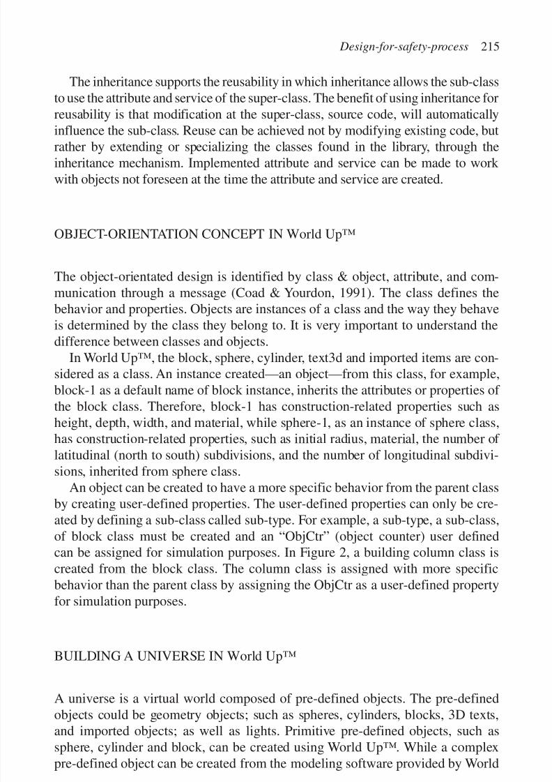
7/14/2019 4DCAD and Visualization in Construction
http://slidepdf.com/reader/full/4dcad-and-visualization-in-construction-56327c6a084e9 224/296
The inheritance supports the reusability in which inheritance allows the sub-classto use the attribute and service of the super-class. The benefit of using inheritance forreusability is that modification at the super-class, source code, will automatically
influence the sub-class. Reuse can be achieved not by modifying existing code, butrather by extending or specializing the classes found in the library, through theinheritance mechanism. Implemented attribute and service can be made to work with objects not foreseen at the time the attribute and service are created.
OBJECT-ORIENTATION CONCEPT IN World Up™
The object-orientated design is identified by class & object, attribute, and com-munication through a message (Coad & Yourdon, 1991). The class defines thebehavior and properties. Objects are instances of a class and the way they behaveis determined by the class they belong to. It is very important to understand thedifference between classes and objects.
In World Up™, the block, sphere, cylinder, text3d and imported items are con-sidered as a class. An instance created—an object—from this class, for example,block-1 as a default name of block instance, inherits the attributes or properties of
the block class. Therefore, block-1 has construction-related properties such asheight, depth, width, and material, while sphere-1, as an instance of sphere class,has construction-related properties, such as initial radius, material, the number of latitudinal (north to south) subdivisions, and the number of longitudinal subdivi-sions, inherited from sphere class.
An object can be created to have a more specific behavior from the parent classby creating user-defined properties. The user-defined properties can only be cre-ated by defining a sub-class called sub-type. For example, a sub-type, a sub-class,
of block class must be created and an “ObjCtr” (object counter) user definedcan be assigned for simulation purposes. In Figure 2, a building column class iscreated from the block class. The column class is assigned with more specificbehavior than the parent class by assigning the ObjCtr as a user-defined propertyfor simulation purposes.
BUILDING A UNIVERSE IN World Up™
A universe is a virtual world composed of pre-defined objects. The pre-definedobjects could be geometry objects; such as spheres, cylinders, blocks, 3D texts,and imported objects; as well as lights. Primitive pre-defined objects, such assphere, cylinder and block, can be created using World Up™. While a complexpre-defined object can be created from the modeling software provided by World
Design-for-safety-process 215

7/14/2019 4DCAD and Visualization in Construction
http://slidepdf.com/reader/full/4dcad-and-visualization-in-construction-56327c6a084e9 225/296
216 S. Rowlinson & B.H.W. Hadikusumo
Figure 2. A generalization–specialization concept in World Up™.

7/14/2019 4DCAD and Visualization in Construction
http://slidepdf.com/reader/full/4dcad-and-visualization-in-construction-56327c6a084e9 226/296
Up™ called World Up™ modeler or third party modeling software such as 3DStudio Max™. Among these three methods, modeling an object using primitiveclass provided inside the World Up™ is the most effective in terms of file size.
Using third party modeling software would lead to a large file size and consequentdegradation of performance, such as texture.An object created using third party modeling software can be used in the
World Up™ universe to the extent that the file format of the object created aresupported by World Up™. Some file formats which are accepted by World Up™are Autodesk DXF format, Wavefront OBJ format, Autodesk 3D Studio mesh file(3ds), Pro/Engineer RENDER SLP file format, MultiGen/ModelGen Flight FLTfile format, VideoScape GEO files, World Up NFF file format and binary NFF fileformat, and Virtual Reality Modeling Language (VRML) 1.0 WRL file format.
REUSING OF OBJECT IN A UNIVERSE DEVELOPMENT
The nature of typical building construction projects, having similar constructioncomponents, provides benefits in the development of a universe in terms of reusing one object to create other similar objects. Reusing of building construc-
tion objects in World Up™ exists at many levels:
• Reusing of objects for different locations. In construction, no two similar com-ponents occupy the same location, i.e. two walls with the same size are installedat different positions. The reusability of an object depends on the type of objectsource itself.
• If the object source is a simple object created using World Up™, such as sphere,block or cylinder, a sub-class representing the object can be created and used tocreate many similar objects with similar properties. The value of translationproperty can be modified to place the new object in the location desired.
• If the object source is created by World Up™ modeler or a third party modeler,the object source can be reused by adding it to the universe through the resourcebrowser (see Fig. 3).
Reusing of objects with different dimensions. Construction components can becreated by using primitive geometry, i.e. columns and beams can be created usingthe block, primitive geometry. The block geometry object source can be stored
as one unit of length, width and depth. This one-unit object source is used in theuniverse as a column by stretching the length, width and depth. Several columns canbe created by using this object source; however, modifying the value of the stretchproperty of any column, for example, also changes the other columns from the sameobject source, the siblings. In order to create a column, as an example, from the sameobject source and also have an independent length, width, and depth control, thecolumn must be assigned as a ForkImported object, a function of World Up™.
Design-for-safety-process 217
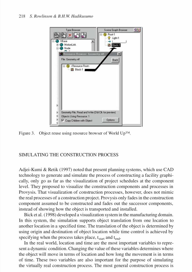
7/14/2019 4DCAD and Visualization in Construction
http://slidepdf.com/reader/full/4dcad-and-visualization-in-construction-56327c6a084e9 227/296
SIMULATING THE CONSTRUCTION PROCESS
Adjei-Kumi & Retik (1997) noted that present planning systems, which use CADtechnology to generate and simulate the process of constructing a facility graphi-cally, only go as far as the visualization of project schedules at the component
level. They proposed to visualize the construction components and processes inProvysis. That visualization of construction processes, however, does not mimicthe real processes of a construction project. Provysis only fades in the constructioncomponent assumed to be constructed and fades out the successor components,instead of showing how the object is transported and installed.
Bick et al. (1998) developed a visualization system in the manufacturing domain.In this system, the simulation supports object translation from one location toanother location in a specified time. The translation of the object is determined by
using origin and destination of object location while time control is achieved byspecifying when the process takes place, tstart and tend.In the real world, location and time are the most important variables to repre-
sent a dynamic condition. Changing the value of these variables determines wherethe object will move in terms of location and how long the movement is in termsof time. These two variables are also important for the purpose of simulatingthe virtually real construction process. The most general construction process is
218 S. Rowlinson & B.H.W. Hadikusumo
Figure 3. Object reuse using resource browser of World Up™.
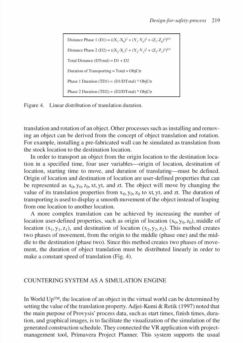
7/14/2019 4DCAD and Visualization in Construction
http://slidepdf.com/reader/full/4dcad-and-visualization-in-construction-56327c6a084e9 228/296
translation and rotation of an object. Other processes such as installing and remov-ing an object can be derived from the concept of object translation and rotation.For example, installing a pre-fabricated wall can be simulated as translation fromthe stock location to the destination location.
In order to transport an object from the origin location to the destination loca-tion in a specified time, four user variables—origin of location, destination of location, starting time to move, and duration of translating—must be defined.
Origin of location and destination of location are user-defined properties that canbe represented as x0, y0, z0, xt, yt, and zt. The object will move by changing thevalue of its translation properties from x0, y0, z0 to xt, yt, and zt. The duration of transporting is used to display a smooth movement of the object instead of leapingfrom one location to another location.
A more complex translation can be achieved by increasing the number of location user-defined properties, such as origin of location (x0, y0, z0), middle of location (x1, y1, z1), and destination of location (x2, y2, z2). This method creates
two phases of movement, from the origin to the middle (phase one) and the mid-dle to the destination (phase two). Since this method creates two phases of move-ment, the duration of object translation must be distributed linearly in order tomake a constant speed of translation (Fig. 4).
COUNTERING SYSTEM AS A SIMULATION ENGINE
In World Up™, the location of an object in the virtual world can be determined bysetting the value of the translation property. Adjei-Kumi & Retik (1997) noted thatthe main purpose of Provysis’ process data, such as start times, finish times, dura-tion, and graphical images, is to facilitate the visualization of the simulation of thegenerated construction schedule. They connected the VR application with project-management tool, Primavera Project Planner. This system supports the usual
Design-for-safety-process 219
Distance Phase 1 (D1) = ((X1-X
0)2 + (Y
1-Y
0)2 + (Z
1-Z
0)2)0.5
Distance Phase 2 (D2) = ((X2-X
1)2 + (Y
2-Y
1)2 + (Z
2-Z
1)2)0.5
Total Distance (DTotal) = D1 + D2
Duration of Transporting = Total = ObjCtr
Phase 1 Duration (TD1) = (D1/DTotal) * ObjCtr
Phase 2 Duration (TD2) = (D2/DTotal) * ObjCtr
Figure 4. Linear distribution of translation duration.

7/14/2019 4DCAD and Visualization in Construction
http://slidepdf.com/reader/full/4dcad-and-visualization-in-construction-56327c6a084e9 229/296
practice of scheduling in the industry. But it does not explain how to control thetime scale. Time scale factor is important to adjust a speed level so that user cananalyze the VR simulation at a desired and controllable speed. If the simulation is
too fast, it may cause dizziness to the user and it will be difficult to observe thesimulation, while a slow simulation may cause impatience.In order to represent time in the World Up™ universe, a counter system is used.
When the simulation is run, World Up™ goes through the entire simulation loopfor each frame that the simulation is run (Fig. 5). The counter works every timeWorld Up™ simulates the universe (Table 1). The counter is increased everytime that a new cycle of simulation is started. Since the counter will be increasedevery frame, an object can be designed to translate whenever the object start
220 S. Rowlinson & B.H.W. Hadikusumo
Table 1. Scheduling comparison between real practice of construction and VRsimulation.
Activity Real practice VR simulation
Time control Calendar CounterTask started As specified date, i.e. As specified counter, i.e.
1 January 2000 when the universe counterreach 200
Task completion Number of days, i.e. 5 days Number of counter, i.e. 100
Tasks Executed
Sensors Update
Paths Play/Records
Universe Tasks
Node Tasks
(bottom to top, right to left)
All Other Object Tasks
Scene Rendered and Displayed
Figure 5. Simulation cycle of World Up™. Source: World Up™ user’s guide (1997).

7/14/2019 4DCAD and Visualization in Construction
http://slidepdf.com/reader/full/4dcad-and-visualization-in-construction-56327c6a084e9 230/296
counter (OSC), a user-defined property, is equal with the counter for a certainduration of ObjCtr, a user-defined property (Fig. 6). For example, an object willbe triggered to translate or move, when the counter is the same as OSC, 300, for
duration of 100 (ObjCtr). So, the object will stop at its last position when thecounter is 400.The increment of the counter determines how fast the object moves. This incre-
ment can be determined by creating an acceleration factor (Acc F) variable, whichis a time scale (Fig. 6). The greater the factor, the faster is the translation of theobject. This time scale factor influences only the speed of counter calculation, notthe number of frames per second at which the universe is rendered, which dependson the computation capability of the computer, number of polygons rendered, num-ber of pixel filled, and the display card. The faster the frame rate is rendered, thebetter quality of graphic animation is performed.
Design-for-safety-process 221
Figure 6. Countering system for simulation engine.

7/14/2019 4DCAD and Visualization in Construction
http://slidepdf.com/reader/full/4dcad-and-visualization-in-construction-56327c6a084e9 231/296
DESIGN-FOR-SAFETY-PROCESS
General Electric developed guidelines for product design in the 1960s, but a significantbenefit was not realized until systematic Design for Assembly (DFA) was introduced inthe 1970s. Other design for “somethings”; such as manufacturability, inspectability,and quality; were developed in the 1980s. Then, in the 1990s, Design for X-Ability(DFX) has been used as an umbrella for all of these terms. The potential of DFX isenhanced by the availability of a powerful representation tool such as VR, wheredesign can be represented in 3D graphical data and a walkthrough function enablingthe user to discuss any aspect of the object in a virtually real location.
VR of components and processes of a construction project will be used to
develop a DFSP methodology, which aims to point out the safety hazards inheritedby the construction components and activities. The main idea of DFSP is derivedfrom DFX. The DFX aims to design a product from many viewpoints or charac-teristics (Gutwald in Prasad, 1996) with the following benefits: achieving a prod-uct exhibiting better qualities of X, i.e. Design for Manufacturability (DFM),DFA, Design for Disassembly, Design for Quality and Design for Environment.
EARLY FAILURE DETECTION
Since DFX is an umbrella, the methodology development depends on the specificdomain of x-ability developed. For example, DFM is designed by utilizing theo-ries, such as the Taguchi method, and design axioms. However, the most impor-tant consideration is that DFX must work as a guideline to evaluate the design.This can be achieved by developing the DFX as an online or offline purpose
(Huang, 1996). An online DFX checks its data/knowledge base to ensure that thedesign decision being considered will not violate the DFX rules. On the otherhand, an offline DFX evaluates design decisions after they are made. In thisresearch, an online DFSP is chosen. The safety process will be designed by utiliz-ing a data/knowledge base compiled from theory and axioms. An axiom is aproposition, which is assumed to be true without proof for the sake of studying theconsequences that follow from it and the axiom cannot be proven, rather it mustbe assumed to be true until a violation or counter-example can be found (Sush et
al., 1978). In this research, the axiom will be compiled from safety regulations andsafety best practice.Several theories of accident causation exist such as accident proneness, goals-
freedom alertness, adjustment-stress, unconscious motivation, situational theories,domino theory, and epidemiological theories (Hale & Hale, 1972; Petersen, 1984).Adams’domino theory of accident causation developed from Heinrich is consideredthe most relevant accident theory to enable safety hazard recognition. The main
222 S. Rowlinson & B.H.W. Hadikusumo

7/14/2019 4DCAD and Visualization in Construction
http://slidepdf.com/reader/full/4dcad-and-visualization-in-construction-56327c6a084e9 232/296
reason is that Adams’ theory of accident causation discusses the tactical error, a tan-gible approach, which contains the unsafe conditions as follows (Adams, 1976):
• improper design, construction or layout;
• decayed, aged, worn, frayed or cracked;• unnecessarily slippery, rough, sharp-edged or sharp-cornered;
• unsafely stored or piled tools or materials;
• poor housekeeping or congestion;
• unsafe established procedure, inadequate job planning, improper equipmentprovided;
• inadequate aisle space;
• improperly guarded;
• improper illumination;• improper ventilation;
• personal protective equipment not adequate or not available.
CONCLUSION
The traditional approach using 2D drawings results in bulky and separated designdrawings and philosophies. This problem leads to difficulties for the end-user inorder to create a 3D mental picture for construction purposes. VR can integratethis design information into one universe and also add in design content such asthe construction process, method, and safety planning.
The reusability concept is important in developing a VR universe since it can min-imize development time. Reusability can be achieved by using the concept of object-orientation; class & object, and inheritance. Inheritance can be created by applying
the concept of generalization–specialization which is also supported by World Up™.The two important variables, location and time, are identified for the purpose of
construction process simulation. In order to translate the object, the location vari-able must be defined as the origin of location and the destination of location. Thetime for object translation can be distributed linearly if the location consists of three points or more, such as (x0, y0, z0), (x1, y1, z1), and (x2, y2, z2) in order toobtain a constant object translation.
Since time must also be represented for the simulation purpose, a counter system,
counterϭ
counterϩ
Acc_F, is proposed which can simulate a time standard, suchas a calendar, in real life. The universe counter will be increased by the factor of “Acc_F” (acceleration factor), which also functions as a time scale to adjust thespeed of the construction process as desired by the user every time a frame is calcu-lated by World Up™. Adjustable speed of simulation is important for user friendli-ness. If the simulation is too fast, the user might get dizzy and might not be able toanalyze the simulation properly, but a slow simulation might cause user’s impatience.
Design-for-safety-process 223

7/14/2019 4DCAD and Visualization in Construction
http://slidepdf.com/reader/full/4dcad-and-visualization-in-construction-56327c6a084e9 233/296
An example of the use of the model is shown in Appendix A. The modelshows a typical 40 story Hong Kong Housing Authority residential block and the model has been used to conduct a safety risk assessment for such
units. The walkthrough was found to be realistic and the hazards identifiedwere automatically logged in the risk assessment.
REFERENCES
Adams, E.E. 1976. Accident causation within the management system. ProfessionalSafety, October.
Adjei-Kumi, T. & Retik, A. 1997. A library-based 4D visualisation of constructionprocesses. IEEE conference on information visualization, 27–29 August : 315–321.ISBN: 0-8186-8076-8.
Bick, B., Kampker, M., Starke, G. & Weyrich, M. 1998. Realistic 3D-visualisation of manufacturing systems based on data of a discrete event simulation. Proceedings of the24th annual conference of the IEEE , Industrial Electronics Society: 2543–2548.
Coad, P. & Yourdon, E. 1991. Object-oriented analysis, 2nd edition. New Jersey: YourdonPress. ISBN 0-13-629981-4.
Faraj, I. & Alshawi, M. 1996. Integrating virtual reality functionality with traditionaldesign tools. DOE Research Contract 39/3/193, Department of Surveying, Universityof Salford, Manchester, U.K.
Furnham, A. 1998. Personality and social behaviour . New York: Arnold.Hadipriono, F.C. & Larew, R.E. 1996. Safety training in virtual construction environment.
Proceedings of the 1st international conference of CIB working commissionW99/Lisbon/Portugal, 4–7 September .
Hale, A.R. & Hale, M. 1972. A review of the industrial accident research literature.London: Her Majesty’s Stationery Office. ISBN: 0113608950.
Huang, G.Q. 1996. Developing design for X tools. Design for X: concurrent engineeringimperatives. London: Chapman & Hall. ISBN: 0-412-78750-4.
Lingard, H. & Rowlinson, S. 1991. Safety in Hong Kong’s construction industry. The Hong Kong Engineer 19: 38–44.Lingard, H. & Rowlinson, S. 1997. Behavior-based safety management in Hong Kong’s
construction industry. Journal of Safety Research 28(4): 243–256.Ng, K.G. 1992. Reusable components for business information systems. Dissertation for
the Master Degree of Science in Data Processing, University of Ulster.Prasad, B. 1996. Concurrent engineering fundamentals Volume 1. New Jersey: Prentice
Hall PTR.Petersen, D. 1984. Human-error reduction and safety management. New York: Aloray
Inc. ISBN: 0-913690-09-0.
Sametinger, J. 1997. Software engineering with reusable components. Berlin: Springer.ISBN 3-540-62695-6.Sush, N.P., Bell, A.C. & Gossard, D.C. 1978. On an axiomatic approach to manufacturing
and manufacturing systems. ASME Journal of Engineering for Industry 100(2).
224 S. Rowlinson & B.H.W. Hadikusumo

7/14/2019 4DCAD and Visualization in Construction
http://slidepdf.com/reader/full/4dcad-and-visualization-in-construction-56327c6a084e9 234/296
APPENDIX A
Design-for-safety-process 225
1. Use of the model to conduct a risk assessment on a Hong Kong Housing Authorityresidential block.
2. The user is observing the project from the ground level.
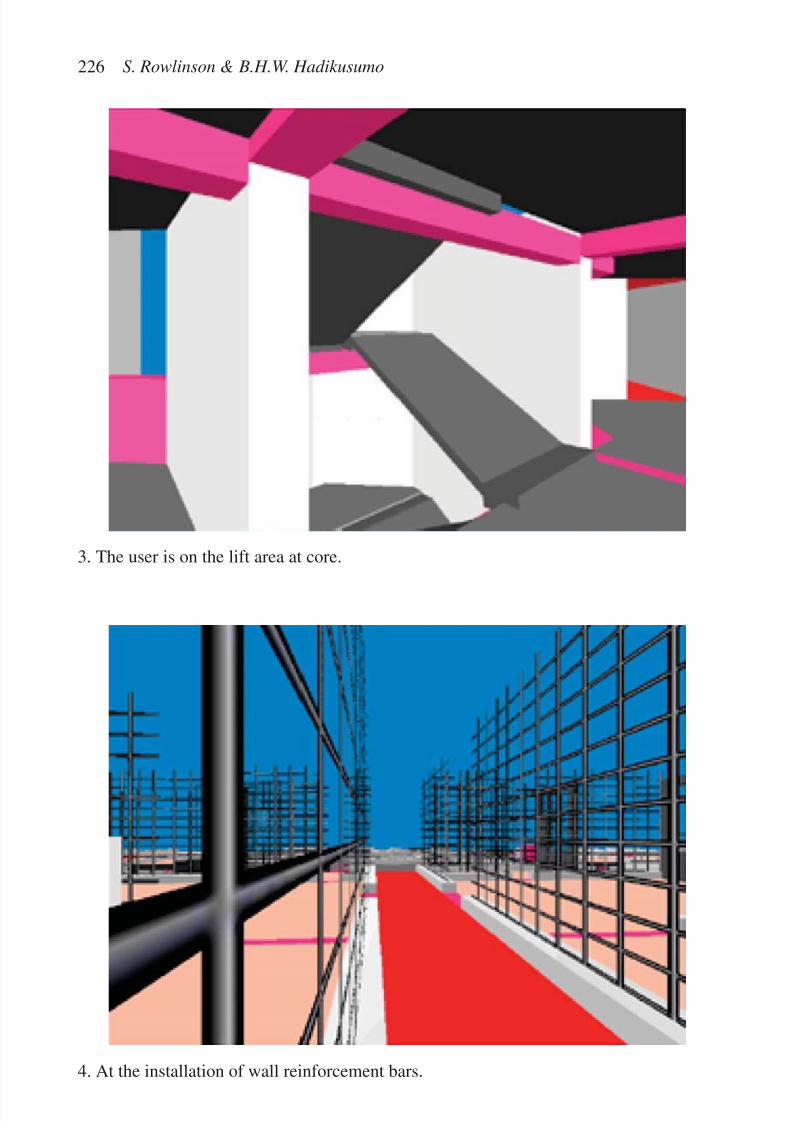
7/14/2019 4DCAD and Visualization in Construction
http://slidepdf.com/reader/full/4dcad-and-visualization-in-construction-56327c6a084e9 235/296
226 S. Rowlinson & B.H.W. Hadikusumo
4. At the installation of wall reinforcement bars.
3. The user is on the lift area at core.

7/14/2019 4DCAD and Visualization in Construction
http://slidepdf.com/reader/full/4dcad-and-visualization-in-construction-56327c6a084e9 236/296
THE POTENTIAL OF 4D CAD AS A TOOL FORCONSTRUCTION MANAGEMENT
Robert M. Webb1, Theo C. Haupt2
1 Bovis Lend Lease, Charlotte, NC, USA2 M.E. Rinker, Sr. School of Building Construction,
University of Florida, Gainesville, FL, USA
227
Abstract
4D CAD presents several opportunities for use as a tool for construction management with
respect to the way that it links the temporal and physical spatial aspects of a construction
project. Bovis Lend Lease has used 4D CAD to graphically represent the relationship
between space and project schedule, through the actual transformation of that space overtime during the construction of a building or facility. When it is considered that construction
managers are constantly on the look out for effective ways to gain competitive edge in a
highly competitive industry, 4D CAD has the potential to provide such an edge. 4D CAD
provides the vehicle by means of which it is possible to integrate the functions, roles, respon-
sibilities and relationships of, and between, all the participants in the construction process.
This process is examined in this paper. Some of the problems, which need to be overcome,
to make 4D CAD more attractive for construction management are also explored.
Keywords: 4D CAD, construction management, visualization, computer simulation
INTRODUCTION
Construction managers are constantly being bombarded by the need to make rapidand informed decisions in order to satisfy the traditional project parameters of
time, cost and quality. Decisions need to facilitate completion within the projectschedule and within the project budget while satisfying the desired quality require-ments. As the number of technological options increases, so does the complexityand the cost of choosing which combination of available options is the mostappropriate for a given application. Informed decisions involve the managementof vast amounts of information about the combinations of available options andthe simulation of their performance (Papamichael, 1999). To further exacerbate
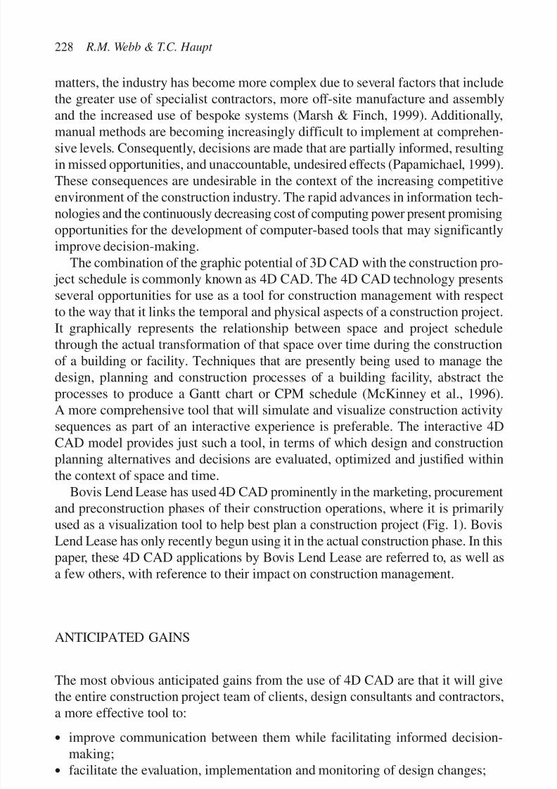
7/14/2019 4DCAD and Visualization in Construction
http://slidepdf.com/reader/full/4dcad-and-visualization-in-construction-56327c6a084e9 237/296
matters, the industry has become more complex due to several factors that includethe greater use of specialist contractors, more off-site manufacture and assemblyand the increased use of bespoke systems (Marsh & Finch, 1999). Additionally,
manual methods are becoming increasingly difficult to implement at comprehen-sive levels. Consequently, decisions are made that are partially informed, resultingin missed opportunities, and unaccountable, undesired effects (Papamichael, 1999).These consequences are undesirable in the context of the increasing competitiveenvironment of the construction industry. The rapid advances in information tech-nologies and the continuously decreasing cost of computing power present promisingopportunities for the development of computer-based tools that may significantlyimprove decision-making.
The combination of the graphic potential of 3D CAD with the construction pro- ject schedule is commonly known as 4D CAD. The 4D CAD technology presentsseveral opportunities for use as a tool for construction management with respectto the way that it links the temporal and physical aspects of a construction project.It graphically represents the relationship between space and project schedulethrough the actual transformation of that space over time during the constructionof a building or facility. Techniques that are presently being used to manage thedesign, planning and construction processes of a building facility, abstract theprocesses to produce a Gantt chart or CPM schedule (McKinney et al., 1996).
A more comprehensive tool that will simulate and visualize construction activitysequences as part of an interactive experience is preferable. The interactive 4DCAD model provides just such a tool, in terms of which design and constructionplanning alternatives and decisions are evaluated, optimized and justified withinthe context of space and time.
Bovis Lend Lease has used 4D CAD prominently in the marketing, procurementand preconstruction phases of their construction operations, where it is primarilyused as a visualization tool to help best plan a construction project (Fig. 1). Bovis
Lend Lease has only recently begun using it in the actual construction phase. In thispaper, these 4D CAD applications by Bovis Lend Lease are referred to, as well asa few others, with reference to their impact on construction management.
ANTICIPATED GAINS
The most obvious anticipated gains from the use of 4D CAD are that it will givethe entire construction project team of clients, design consultants and contractors,a more effective tool to:
• improve communication between them while facilitating informed decision-making;
• facilitate the evaluation, implementation and monitoring of design changes;
228 R.M. Webb & T.C. Haupt
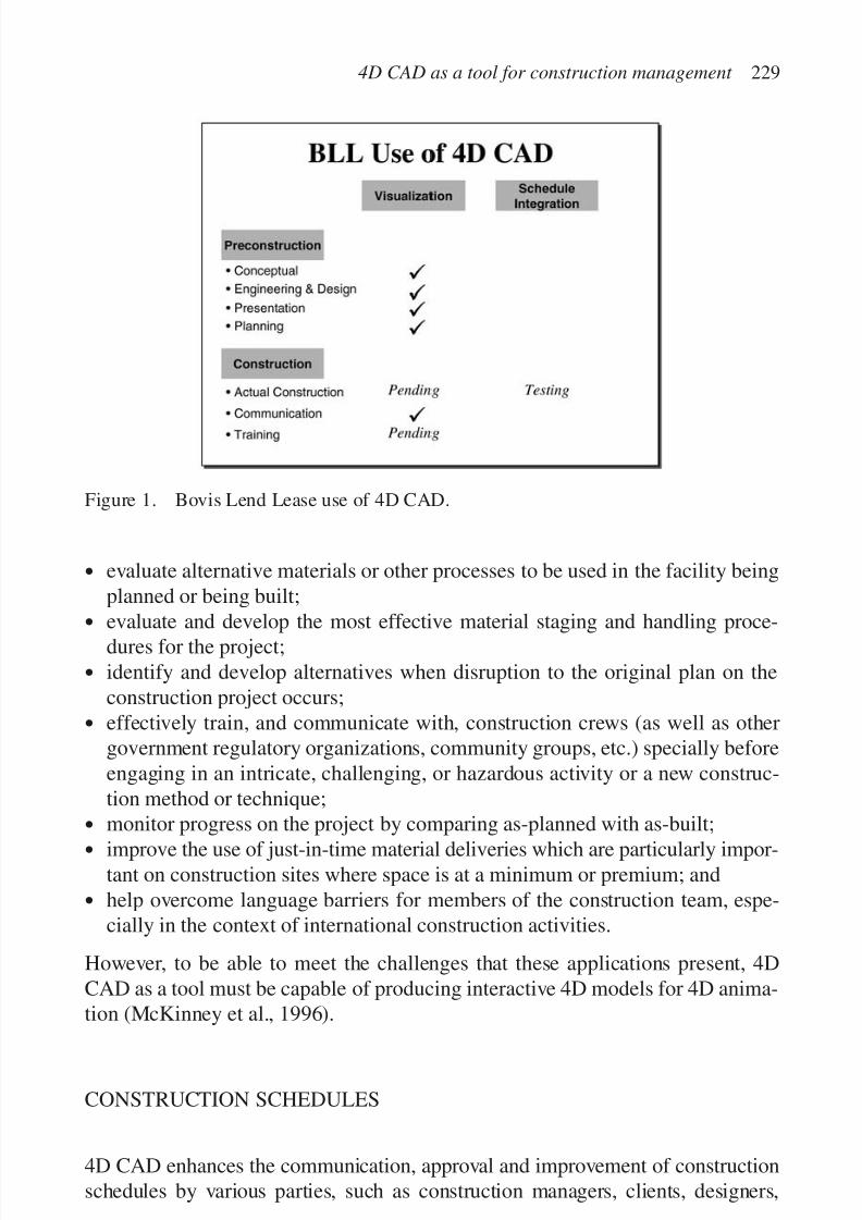
7/14/2019 4DCAD and Visualization in Construction
http://slidepdf.com/reader/full/4dcad-and-visualization-in-construction-56327c6a084e9 238/296
• evaluate alternative materials or other processes to be used in the facility beingplanned or being built;
• evaluate and develop the most effective material staging and handling proce-dures for the project;
• identify and develop alternatives when disruption to the original plan on theconstruction project occurs;
• effectively train, and communicate with, construction crews (as well as othergovernment regulatory organizations, community groups, etc.) specially beforeengaging in an intricate, challenging, or hazardous activity or a new construc-tion method or technique;
• monitor progress on the project by comparing as-planned with as-built;
• improve the use of just-in-time material deliveries which are particularly impor-tant on construction sites where space is at a minimum or premium; and
• help overcome language barriers for members of the construction team, espe-cially in the context of international construction activities.
However, to be able to meet the challenges that these applications present, 4DCAD as a tool must be capable of producing interactive 4D models for 4D anima-tion (McKinney et al., 1996).
CONSTRUCTION SCHEDULES
4D CAD enhances the communication, approval and improvement of constructionschedules by various parties, such as construction managers, clients, designers,
4D CAD as a tool for construction management 229
Figure 1. Bovis Lend Lease use of 4D CAD.

7/14/2019 4DCAD and Visualization in Construction
http://slidepdf.com/reader/full/4dcad-and-visualization-in-construction-56327c6a084e9 239/296
sub-contractors and community members. For 4D CAD to be implemented effec-tively, however, a considerable amount of detail work is necessary that is projectspecific, and in many cases unique. Too little detail may result in critical elements of
a work sequence being overlooked, or in a lack of allowances for uncertainty (Riley,1998). Each construction project schedule is normally unique to a particular project.Very rarely it is possible that a set of schedule standards can be applied universallyto multiple projects. By implication, the effort to associate the element of time orschedule with every single component in the 3D CAD system for a single projecthas to be repeated for each successive or new project.
This process is further exacerbated by the many factors that impact a projectconstruction schedule. Consequently, its universal incorporation becomes increas-ingly more arduous and difficult. Some of the factors identified during a surveythat was conducted among numerous schedulers, superintendents, project man-agers and other leaders within Bovis Lend Lease, are listed below in random order:
• changing weather and site conditions;
• availability of labor and materials, and use of specialty components infacility;
• regulatory requirements such as agency approvals and permitting;
• experience of project team, changes in project team during project, and project
team preferences;• owner involvement, approval and sign-off procedures (how much and fast),critical decisions and activities;
• technical complexity of facility components, site logistics and staging capabilities;
• trade contractor or sub-contractor performance;
• amount of design changes, speed with which changes to design are handled,schematic design, estimate and approval duration;
• involvement and requirements of community groups and trade unions withrespect, for example, to minority requirements;
• legal contract requirements, bidding phase procedures, and documentation(volume and complexity), project budget and funding;
• environmental factors and compliance requirements;
• availability, condition and dependence on local utilities or infrastructure such asroads and rail;
• amount of value engineering process;
• site security; and
• safety requirements/accident impact.
Considering these factors, it is not surprising that contractors have not harnessedthe potential that is presented by 4D CAD. For this scenario to change, the 4DCAD tool must empower construction designers, schedulers, superintendents andproject managers to develop a project schedule directly related to a 3D model of the building facility (McKinney et al., 1996). At the same time, it is also necessaryfor the spatial and temporal relationships involved in the project, to be understood.
230 R.M. Webb & T.C. Haupt

7/14/2019 4DCAD and Visualization in Construction
http://slidepdf.com/reader/full/4dcad-and-visualization-in-construction-56327c6a084e9 240/296
DEPLOYMENT OF 4D CAD STRATEGY
The simple “visualization” use of 4D CAD is becoming relatively commonplacetoday. To date, Bovis Lend Lease and many other companies have deployed itacross multiple market sectors and project sizes around the world. Some of themore common market sectors where it has been more routinely used include:
• Industrial,
• Semi-conductor,
• Pharmaceutical,
• Healthcare,
• Office Mixed Use, and• Telecommunications.
Deployment of the schedule integration for actual construction is proving to bechallenging and hard to achieve. Consequently, deploying, with schedule integra-tion, remains very much an inexact science. Significantly more upfront commit-ment of project planning, resources and finances is needed. Very few projectsglobally have been completed using full 4D CAD schedule integration. While thisis true, 4D CAD with schedule integration is feasible on any project, and makesthe most long-term sense on the larger and more complex ones.
4D CAD AS A VISUALIZATION AND SIMULATION TOOL
Several factors influence the selection of appropriate construction methods andrelated resources that impact the traditional project parameters of time, cost and
quality (Liu, 1996). These factors include:
• job specification,
• job size,
• site conditions,
• materials, and
• availability of equipment and suitably skilled labor.
Computer simulation provides a practical visual means of modeling constructionactivities and operations and identifying the characteristics of these before theyactually begin (Liu, 1996). This simulation enables the creation of models thatprovide manipulative opportunities to construct situations that would not havebeen otherwise accessible (Horne et al., 1999). Experimenting with “what-if”scenarios on the computer model to arrive at the optimal operational plan can testdecisions, and alternatives.
4D CAD as a tool for construction management 231
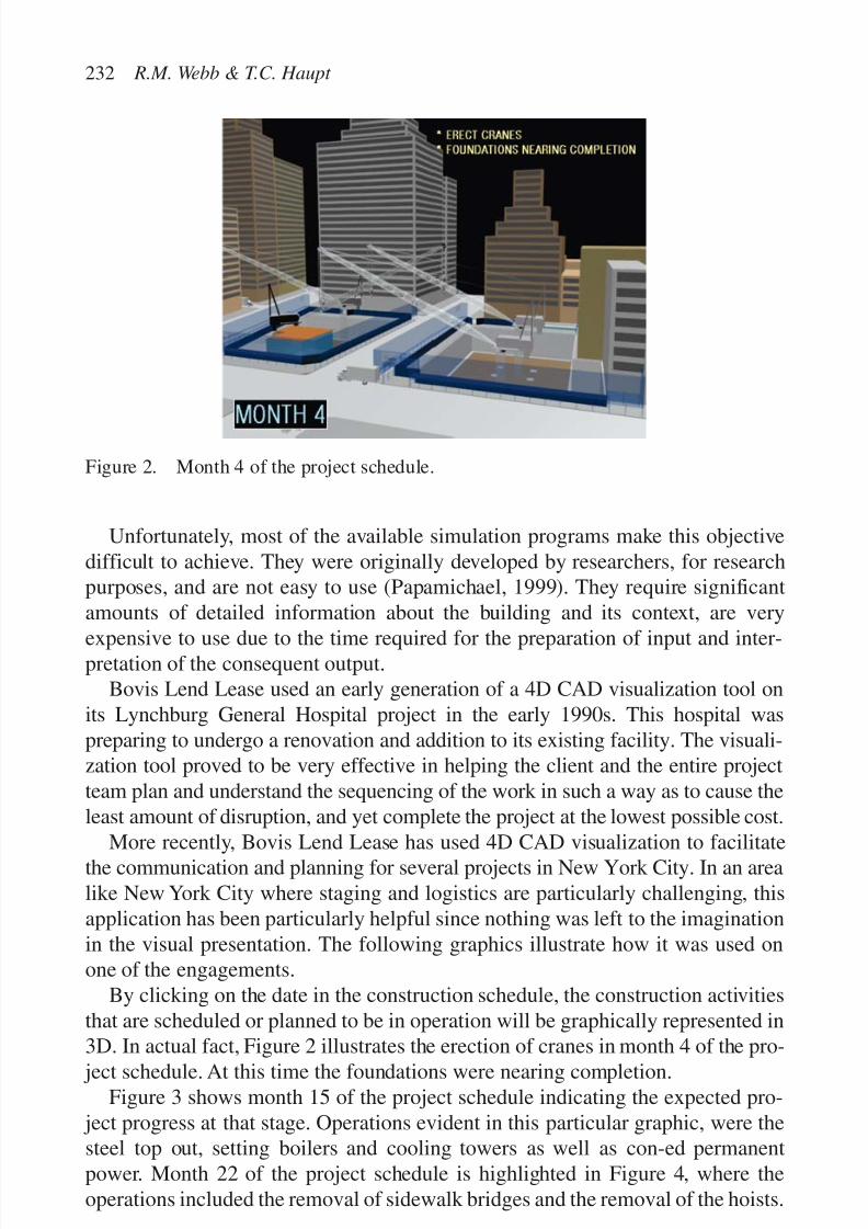
7/14/2019 4DCAD and Visualization in Construction
http://slidepdf.com/reader/full/4dcad-and-visualization-in-construction-56327c6a084e9 241/296
Unfortunately, most of the available simulation programs make this objectivedifficult to achieve. They were originally developed by researchers, for researchpurposes, and are not easy to use (Papamichael, 1999). They require significantamounts of detailed information about the building and its context, are very
expensive to use due to the time required for the preparation of input and inter-pretation of the consequent output.
Bovis Lend Lease used an early generation of a 4D CAD visualization tool onits Lynchburg General Hospital project in the early 1990s. This hospital waspreparing to undergo a renovation and addition to its existing facility. The visuali-zation tool proved to be very effective in helping the client and the entire projectteam plan and understand the sequencing of the work in such a way as to cause theleast amount of disruption, and yet complete the project at the lowest possible cost.
More recently, Bovis Lend Lease has used 4D CAD visualization to facilitatethe communication and planning for several projects in New York City. In an arealike New York City where staging and logistics are particularly challenging, thisapplication has been particularly helpful since nothing was left to the imaginationin the visual presentation. The following graphics illustrate how it was used onone of the engagements.
By clicking on the date in the construction schedule, the construction activitiesthat are scheduled or planned to be in operation will be graphically represented in3D. In actual fact, Figure 2 illustrates the erection of cranes in month 4 of the pro-
ject schedule. At this time the foundations were nearing completion.Figure 3 shows month 15 of the project schedule indicating the expected pro-
ject progress at that stage. Operations evident in this particular graphic, were thesteel top out, setting boilers and cooling towers as well as con-ed permanentpower. Month 22 of the project schedule is highlighted in Figure 4, where theoperations included the removal of sidewalk bridges and the removal of the hoists.
232 R.M. Webb & T.C. Haupt
Figure 2. Month 4 of the project schedule.

7/14/2019 4DCAD and Visualization in Construction
http://slidepdf.com/reader/full/4dcad-and-visualization-in-construction-56327c6a084e9 242/296
It is clearly evident from this example how effectively 4D CAD can capture,and dynamically manage, the interaction between project components andresources over time, visualize these interactions, and support the real-time inter-action of users with the 4D model. With this tool, it is possible to enhance the
communication, approval and improvement of construction schedules by variousparticipants in the construction process, such as construction managers, clients,designers, sub-contractors and community members.
It is also possible to demonstrate the environmental impacts of the proposedproject in order to allay fears, and gather support for it.
Another one of the popular software packages on the market that is used for4D CAD visualization allows the project team members of a project to streamline
4D CAD as a tool for construction management 233
Figure 3. Month 15 of the project schedule.
Figure 4. Month 22 of the project schedule.

7/14/2019 4DCAD and Visualization in Construction
http://slidepdf.com/reader/full/4dcad-and-visualization-in-construction-56327c6a084e9 243/296
parallel workflow (Fig. 5). In a typical project environment, detailed engineeringand scheduling run in two simultaneous yet independent work processes. This appli-cation integrates the design and construction planning disciplines, improvingconstructability and shortening the time from project concept to project completion.
Overall, this particular 4D CAD application can potentially provide the follow-ing benefits:
• definition of the scope of projects at project proposal and conceptual designstages;
• early development of a construction and commissioning or start-up methodstatement;
• involvement of construction and commissioning personnel in conceptualdesign stage;
• full investigation of design, constructability and commissioning issues prior tocommitment of costly site resources;
• improved design and procurement strategies;
• better focus on pre-fabrication, pre-assembly and just-in-time procurement;
• smooth materials management and handling; and• exploration of alternative dispute resolutions.
Bovis Lend Lease used a fairly specialized 4D CAD visualization tool on a pro- ject in Sydney, Australia. On this 50-story tower, there was a need to keep thereinforced concrete frame as light and open as possible while still being adequatefor wind and other general structural requirements. The Strand 7 software tool was
234 R.M. Webb & T.C. Haupt
Figure 5. Parallel workflow.

7/14/2019 4DCAD and Visualization in Construction
http://slidepdf.com/reader/full/4dcad-and-visualization-in-construction-56327c6a084e9 244/296
used to model the core structure. Wind was then introduced in time intervals to testfor flaws in the design. Figures 6 and 7 illustrate some of the individual sequencesfrom this visualization tool. This process added significant value resulting in astructurally sound building being constructed without the traditional amount of reinforcement that might have been required. The open, airy appearance of thebuilding added to its aesthetic. The addition of open space throughout the struc-ture was an added benefit.
ILLUSTRATION OF 4D CAD WITH SCHEDULE INTEGRATION
Bovis Lend Lease is actively using 4D CAD with schedule integration on a mixeduse office park in London. This engagement has the essential ingredients forallowing 4D CAD to make a meaningful contribution; a very supportive team
4D CAD as a tool for construction management 235
Figure 6. Bovis Lend Lease project in Australia.
Figure 7. Bovis Lend Lease project in Australia.

7/14/2019 4DCAD and Visualization in Construction
http://slidepdf.com/reader/full/4dcad-and-visualization-in-construction-56327c6a084e9 245/296
comprising of owner, design team, construction manager and key trade contrac-tors. The initial objectives of the project team for this effort were as follows:
• to graphically represent planned progress element by element;
• to integrate graphical representation in time terms with current planning systems;• to involve trade contractors to a greater degree in the planning process by
giving them the opportunity to test their individual programs on the model;
• to have greater discipline in the process with both planners and trade contractors;
• to provide a tool to graphically test on-site program scenarios and recovery pro-grams; and
• to provide historical records with respect to progress achieved and the reasonsfor that progress.
The following elements were built into the 3D models for all three buildingsmaking up the project:
• all foundations for the concrete columns, steel core and external steel columns;
• all concrete columns for the undercroft to the third floor level;
• all floor slabs;
• steel core;
• external glazing;
• external staircases, steel bracing and external metal sun shade louvres;• roof mounted mechanical plant;
• all external glazing;
• raised floors;
• wall construction around the steel core; and
• buildings to be positioned according to the site plan.
Figures 8 to 10 illustrate several specific times during the sequencing of one of theoffice buildings in the project.
Figures 11 to 13 are another illustration of project sequence on the office projectin London.
236 R.M. Webb & T.C. Haupt
Figure 8. Bovis Lend Lease project in the United Kingdom.
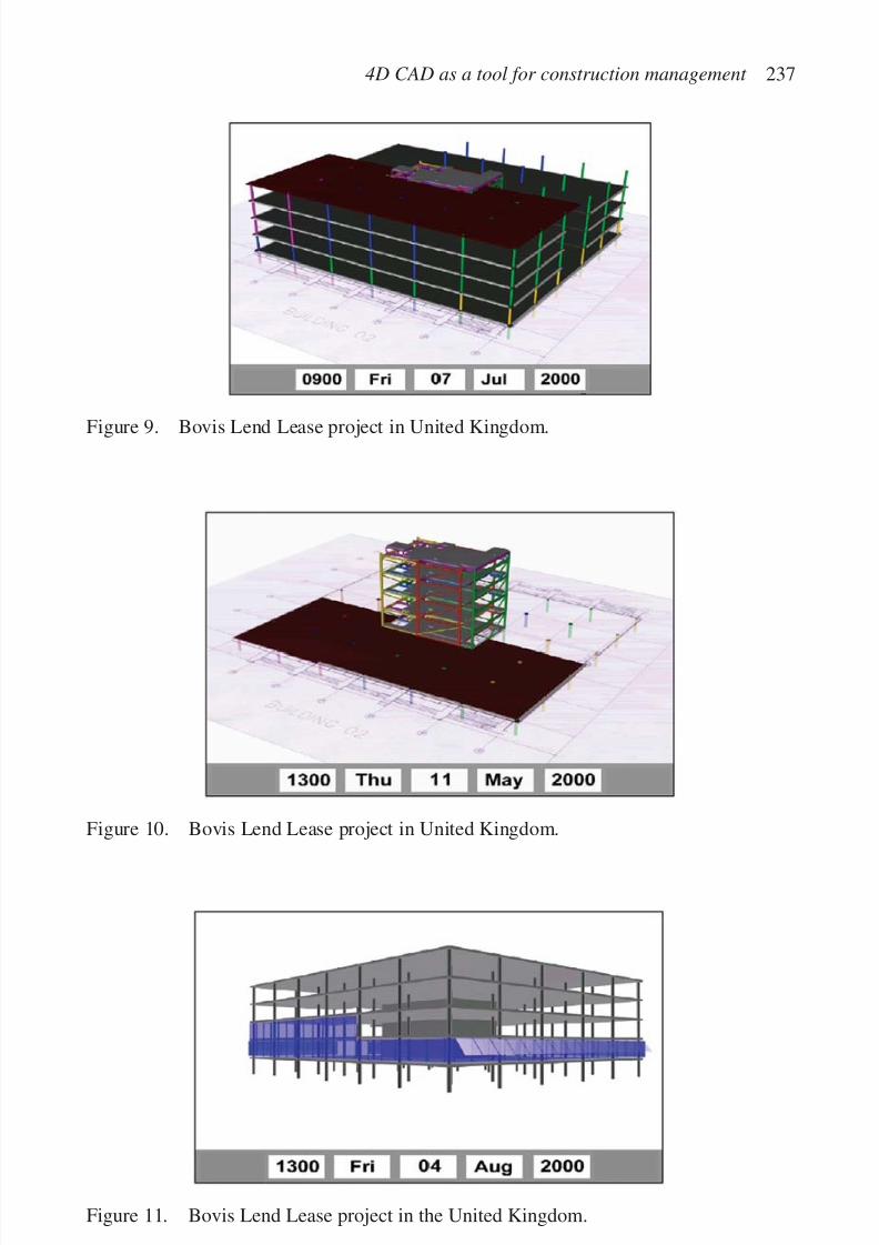
7/14/2019 4DCAD and Visualization in Construction
http://slidepdf.com/reader/full/4dcad-and-visualization-in-construction-56327c6a084e9 246/296
4D CAD as a tool for construction management 237
Figure 9. Bovis Lend Lease project in United Kingdom.
Figure 11. Bovis Lend Lease project in the United Kingdom.
Figure 10. Bovis Lend Lease project in United Kingdom.

7/14/2019 4DCAD and Visualization in Construction
http://slidepdf.com/reader/full/4dcad-and-visualization-in-construction-56327c6a084e9 247/296
LESSONS LEARNED FROM 4D CAD WITH SCHEDULEINTEGRATION
The time required to build a model
The problem of design complexity versus programming time is one that poses thegreatest risk to the successful development of the 4D CAD system being ready intime for use on a project. The current models are in a CAD platform and then ani-mated, allowing them to operate a significant level of detail. This level of detail,however, carries with it a lengthy programming period.
The fact that computers can handle complexity does not mean that there is noneed to design for simplicity. The model does not necessarily have to be as pow-erful as the CAD program. A simple stick model which can be built and operated
238 R.M. Webb & T.C. Haupt
Figure 13. Bovis Lend Lease project in the United Kingdom.
Figure 12. Bovis Lend Lease project in the United Kingdom.

7/14/2019 4DCAD and Visualization in Construction
http://slidepdf.com/reader/full/4dcad-and-visualization-in-construction-56327c6a084e9 248/296
by a contractor operative may be more usable and adaptable to change than acumbersome all singing, all dancing model. Intricate details are not necessary ona 4D CAD tool. These details can be viewed adequately on detailed design draw-
ings from either the trades or consultants.
Simplification of the model
With this point in mind, a simplification of the system currently being devel-oped by the architect, sacrificing detail for usability, may offer a product that ismore functional than the current envisaged format. The adaptation of the modelcurrently being developed by the architect is a result of a hybrid of ideas frommultiple sources, i.e. contractor, owner, consultants and architect. Indeed, simpli-
fication arises from knowing the job intimately; from a stand-back perspective oreven from an innocent look at the project from the eyes of an outsider.Alternatively, the current system of modeling might be used on projects where
the design is more complete and perhaps more basic. The design and build formof contract where the contractor heavily influences the design, may have moremerit than a Contract Management contract where the design is still evolvingwhen construction has often started.
Project team summary observation
Given the complexity involved in building a 4D CAD model with the level of detail and chronological animation used on this project, impracticalities mightoccur in the sheer amount of time required to produce such a model. As design isvery rarely 100% complete prior to construction, it is unrealistic to expect thedesign to be sufficiently evolved early enough before construction to allow adetailed model to be built. Perhaps this product should be viewed initially as aproblem-solving tool for complex interface areas on projects. Then, by followingthe natural evolution of a product in regular use, the ease and speed of operation
should increase and the role could be expanded.
OPPORTUNITY FOR CONSTRUCTION PROCESS IMPROVEMENT
The construction industry reputedly still suffers from one of the highest waste fac-
tors of all industries. It has been estimated that 25% of building costs in the UnitedStates are due to waste (CIOB, 1994). The introduction of 4D CAD technologyinto construction management could help reduce construction waste significantly.If the use of 4D CAD tools could reduce the cost of waste by 10%, the savingsto the US $380 billion construction industry would be approximately US $38 bil-lion, enough incentive to actively pursue 4D CAD or other efforts to reduce thiswaste factor.
4D CAD as a tool for construction management 239
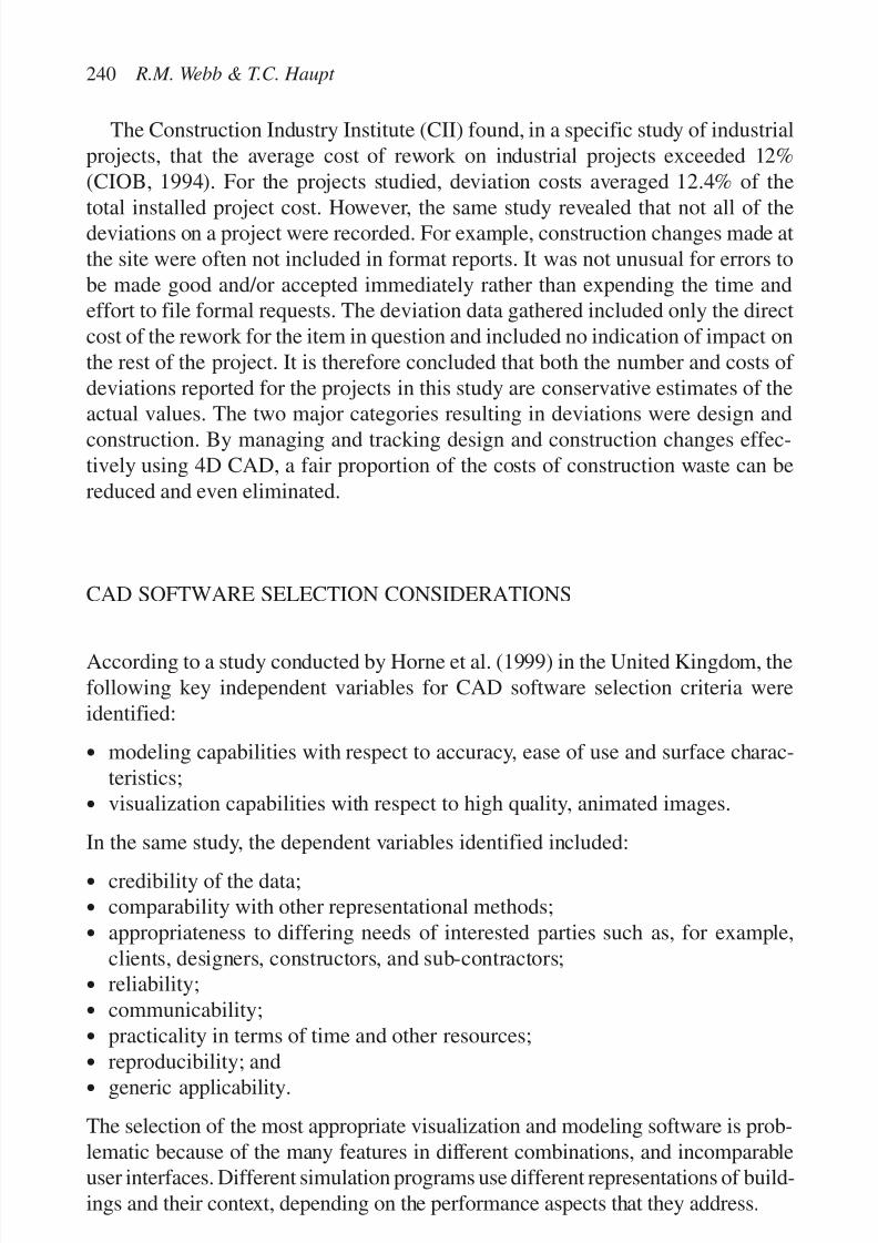
7/14/2019 4DCAD and Visualization in Construction
http://slidepdf.com/reader/full/4dcad-and-visualization-in-construction-56327c6a084e9 249/296
The Construction Industry Institute (CII) found, in a specific study of industrialprojects, that the average cost of rework on industrial projects exceeded 12%(CIOB, 1994). For the projects studied, deviation costs averaged 12.4% of the
total installed project cost. However, the same study revealed that not all of thedeviations on a project were recorded. For example, construction changes made atthe site were often not included in format reports. It was not unusual for errors tobe made good and/or accepted immediately rather than expending the time andeffort to file formal requests. The deviation data gathered included only the directcost of the rework for the item in question and included no indication of impact onthe rest of the project. It is therefore concluded that both the number and costs of deviations reported for the projects in this study are conservative estimates of theactual values. The two major categories resulting in deviations were design andconstruction. By managing and tracking design and construction changes effec-tively using 4D CAD, a fair proportion of the costs of construction waste can bereduced and even eliminated.
CAD SOFTWARE SELECTION CONSIDERATIONS
According to a study conducted by Horne et al. (1999) in the United Kingdom, thefollowing key independent variables for CAD software selection criteria wereidentified:
• modeling capabilities with respect to accuracy, ease of use and surface charac-teristics;
• visualization capabilities with respect to high quality, animated images.
In the same study, the dependent variables identified included:
• credibility of the data;
• comparability with other representational methods;
• appropriateness to differing needs of interested parties such as, for example,clients, designers, constructors, and sub-contractors;
• reliability;
• communicability;
• practicality in terms of time and other resources;
• reproducibility; and• generic applicability.
The selection of the most appropriate visualization and modeling software is prob-lematic because of the many features in different combinations, and incomparableuser interfaces. Different simulation programs use different representations of build-ings and their context, depending on the performance aspects that they address.
240 R.M. Webb & T.C. Haupt

7/14/2019 4DCAD and Visualization in Construction
http://slidepdf.com/reader/full/4dcad-and-visualization-in-construction-56327c6a084e9 250/296
CONCLUSION
While 4D CAD has potential for improving construction management, providingcompetitive edge, reducing construction waste and costs, contractors have not yetaccepted this potential on a large scale, especially in the area of construction man-agement. The 4D CAD tool empowers construction designers, schedulers, super-intendents, and project managers to develop a project schedule directly related toa 3D model of the building facility while at the same time, facilitating the under-standing of the spatial and temporal relationships involved. Furthermore, 4D CADtechnology will need to be available at a more affordable cost to enable it to beapplied to jobs other than large, complex projects, both with respect to physical
enormity as well as dollars.Additionally, consideration has to be given to how the geometry of architectural
form and structural design produced by architects and engineers can more easilyform the basis for 3D representation while being linked at the same time to a con-struction schedule on a fully integrated basis. This aspect is essential if 4D CADis to become the effective tool that it has potential to be with respect to construc-tion project management.
Interoperability of software is essential for the continued development and
deployment of 4D CAD. Central to this effort is the work being done by theInternational Alliance for Interoperability (IAI). This group is supporting stan-dards that allow objects to transfer seamlessly from one application to the next.Additionally, the aecXML effort is quite important to the continued developmentof 4D CAD. This technology provides an effective, cross-platform, cross-applicationtransfer of defined information objects.
Other areas of concern include the process of performance evaluation, the com-plexity of design information with respect to matching design and context parametersthat are in conflict, and information overload caused by each decision being depend-ent on a large number of other decisions. Essential to the continued evolution andbenefits of 4D CAD is the improvement of the environment in which it is to be used.4D CAD needs to be promoted at all levels of the industry, including owners, con-tractors, designers, consultants, trade contractors. By having more projects onlinedoing electronic collaboration will likely also increase the potential use of 4D CAD.
While the potential benefits of 4D CAD for construction management are notin dispute, the challenge faces software designers to produce an integrated systemwhich can effectively address the concerns raised on a cost- and time-effective
basis. Collaborative efforts across the various building construction related disci-plines are necessary to realize the overall vision of a computerized building indus-try. The ideal with respect to construction management would be multiplesimulation tools and multiple databases that are all interoperable in a distributed,networked environment between all participants in the construction process andbeyond, to the eventual end-user.
4D CAD as a tool for construction management 241

7/14/2019 4DCAD and Visualization in Construction
http://slidepdf.com/reader/full/4dcad-and-visualization-in-construction-56327c6a084e9 251/296
REFERENCES
Horne, M., Hill, R. & Giddings, R. 1999. Visualization of photovoltaic clad buildings.
Building Research and Information 27(2): 96–108.Liu, L.Y. 1996. ACPSS—Animated construction process simulation system. Computing
in civil engineering; Proceedings of the third congress, Anaheim, California, 17 –19 June: 397–403. New York: American Society of Civil Engineers.
Marsh, L.E. & Finch, E.F. 1999. Using portable data files in the construction supply chain. Building Research and Information 27(3): 127–139.
McKinney, K., Kim, J., Fischer, M. & Howard, C. 1996. Interactive 4D CAD. Computingin civil engineering; Proceedings of the third congress, Anaheim, California, 17 –19 June: 383–389. New York: American Society of Civil Engineers.
Papamichael, K. 1999. Application of information technologies in building designdecisions. Building Research and Information 27(1): 20–34.
Riley, D.R. 1998. 4D space planning specification development for construction work spaces. Computing in civil engineering; Proceedings of international computingcongress, Boston, Massachusetts, 18–21 October: 354–363. Virginia: American Societyof Civil Engineers.
The Chartered Institute of Building (CIOB) 1994. Constructing total quality handbook : 7.Berkshire: CIOB.
242 R.M. Webb & T.C. Haupt

7/14/2019 4DCAD and Visualization in Construction
http://slidepdf.com/reader/full/4dcad-and-visualization-in-construction-56327c6a084e9 252/296
VIRTUAL REALITY: A SOLUTION TO SEAMLESSTECHNOLOGY INTEGRATION IN THE AEC INDUSTRY?
Raja R.A. Issa
M.E. Rinker, Sr. School of Building Construction,
University of Florida, Gainesville, FL, USA
243
Abstract
A construction project is often divided into work packages because of its complexity.
Although the construction of a big project becomes easier in a specialized industry, it also
brings difficulty to the communication and cooperation between the participants of the
project. It is proposed that a computer-integrated system may reduce the downsidesbrought by the fragmentation of the construction industry and improve the productivity and
efficiency of the construction project. Different models of integration have been suggested,
however, a uniformly accepted integration system has not yet been defined. The introduc-
tion of virtual reality (VR) technology into integration research may provide a general
solution to this dilemma. A VR platform supported by knowledge-based database systems
can become the main interface to construction information for every specialty throughout
the construction (life) cycle of the project. All major application packages would be devel-
oped under or integrated in the VR system. As a consequence, we can foresee a marked
decrease in legal disputes among the owner, architect, and constructor because of misin-terpretation of design drawings and specifications and unmet owner expectations.
Keywords: construction industry, integrated construction environment (ICE), project
modeling and integration, immersive, non-immersive, virtual reality
INTRODUCTION
In order for virtual reality (VR) applications to be successfully implemented in acomplex industry such as construction, they must be part of a vertically integratedconstruction environment (ICE). Whether immersive or non-immersive tech-niques are used in the VR applications, users must be able to visualize design andconstruction information in 3D, photo-realistic, and interactive images. The user
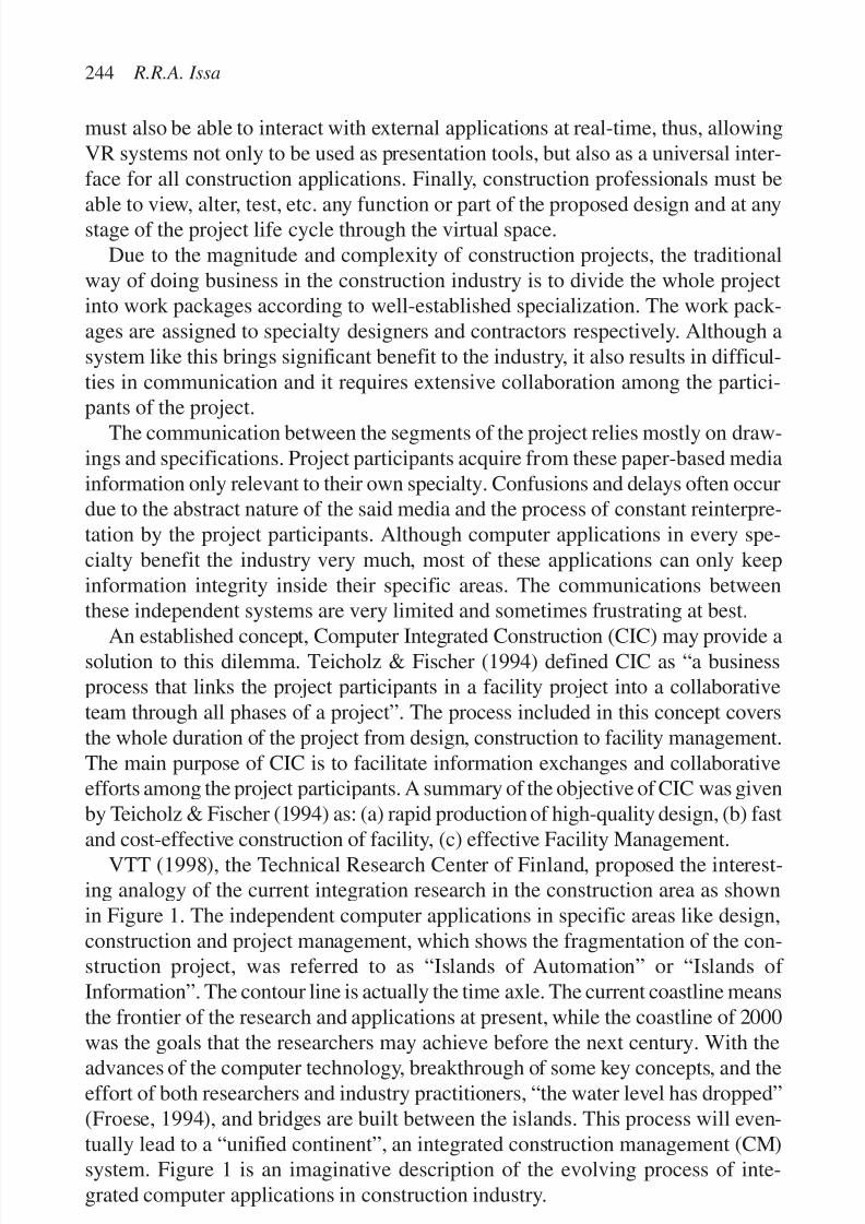
7/14/2019 4DCAD and Visualization in Construction
http://slidepdf.com/reader/full/4dcad-and-visualization-in-construction-56327c6a084e9 253/296
must also be able to interact with external applications at real-time, thus, allowingVR systems not only to be used as presentation tools, but also as a universal inter-face for all construction applications. Finally, construction professionals must be
able to view, alter, test, etc. any function or part of the proposed design and at anystage of the project life cycle through the virtual space.Due to the magnitude and complexity of construction projects, the traditional
way of doing business in the construction industry is to divide the whole projectinto work packages according to well-established specialization. The work pack-ages are assigned to specialty designers and contractors respectively. Although asystem like this brings significant benefit to the industry, it also results in difficul-ties in communication and it requires extensive collaboration among the partici-pants of the project.
The communication between the segments of the project relies mostly on draw-ings and specifications. Project participants acquire from these paper-based mediainformation only relevant to their own specialty. Confusions and delays often occurdue to the abstract nature of the said media and the process of constant reinterpre-tation by the project participants. Although computer applications in every spe-cialty benefit the industry very much, most of these applications can only keepinformation integrity inside their specific areas. The communications betweenthese independent systems are very limited and sometimes frustrating at best.
An established concept, Computer Integrated Construction (CIC) may provide asolution to this dilemma. Teicholz & Fischer (1994) defined CIC as “a businessprocess that links the project participants in a facility project into a collaborativeteam through all phases of a project”. The process included in this concept coversthe whole duration of the project from design, construction to facility management.The main purpose of CIC is to facilitate information exchanges and collaborativeefforts among the project participants. A summary of the objective of CIC was givenby Teicholz & Fischer (1994) as: (a) rapid production of high-quality design, (b) fast
and cost-effective construction of facility, (c) effective Facility Management.VTT (1998), the Technical Research Center of Finland, proposed the interest-
ing analogy of the current integration research in the construction area as shownin Figure 1. The independent computer applications in specific areas like design,construction and project management, which shows the fragmentation of the con-struction project, was referred to as “Islands of Automation” or “Islands of Information”. The contour line is actually the time axle. The current coastline meansthe frontier of the research and applications at present, while the coastline of 2000
was the goals that the researchers may achieve before the next century. With theadvances of the computer technology, breakthrough of some key concepts, and theeffort of both researchers and industry practitioners, “the water level has dropped”(Froese, 1994), and bridges are built between the islands. This process will even-tually lead to a “unified continent”, an integrated construction management (CM)system. Figure 1 is an imaginative description of the evolving process of inte-grated computer applications in construction industry.
244 R.R.A. Issa
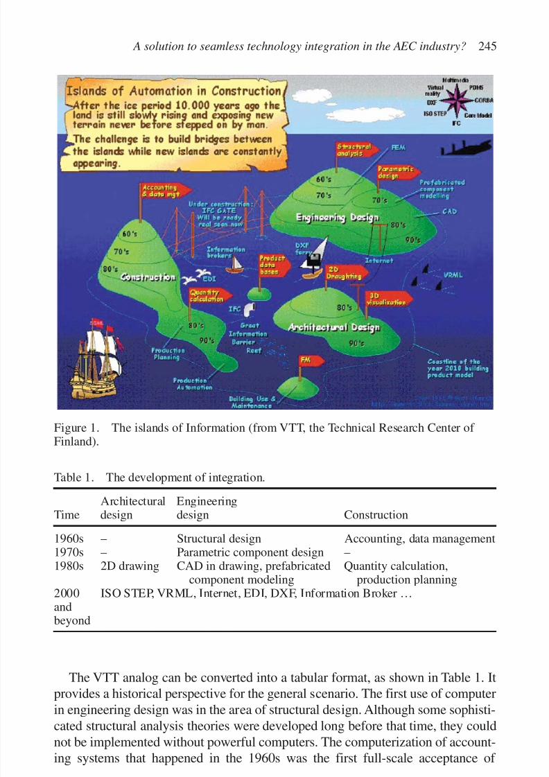
7/14/2019 4DCAD and Visualization in Construction
http://slidepdf.com/reader/full/4dcad-and-visualization-in-construction-56327c6a084e9 254/296
The VTT analog can be converted into a tabular format, as shown in Table 1. Itprovides a historical perspective for the general scenario. The first use of computerin engineering design was in the area of structural design. Although some sophisti-cated structural analysis theories were developed long before that time, they couldnot be implemented without powerful computers. The computerization of account-ing systems that happened in the 1960s was the first full-scale acceptance of
A solution to seamless technology integration in the AEC industry? 245
Figure 1. The islands of Information (from VTT, the Technical Research Center of Finland).
Table 1. The development of integration.
Architectural EngineeringTime design design Construction
1960s – Structural design Accounting, data management1970s – Parametric component design –1980s 2D drawing CAD in drawing, prefabricated Quantity calculation,
component modeling production planning2000 ISO STEP, VRML, Internet, EDI, DXF, Information Broker …andbeyond

7/14/2019 4DCAD and Visualization in Construction
http://slidepdf.com/reader/full/4dcad-and-visualization-in-construction-56327c6a084e9 255/296
computer application in business management. At the same time, computers alsobegan to be used in construction process.
The development of computer hardware advanced in the 1980s to enable higher
graphic processing ability. CAD, which stands for “Computer Aided Design”,became popular. However, it is more like “Computer Aided Drawing” in mostcases. The software that was used to generate drawings for the construction ormanufacturing process had difficulty exchanging information with other software,such as structural analysis or other computation software. Estimating software,which is closely related to accounting system, came into use in the 1980s. Duringthis time the CPM method was computerized as well and became the mainstreamof construction planning software.
The great advances in technology integration came in the 1990s. Our wholesociety was affected by the fast development of computer technology. CAD tech-nology advanced from 2D drawings to 3D visualization and VR using VRMLbecame possible. It was recognized that the lack of integration between computerapplications in this area could become a major obstacle to the further develop-ment. Integration plans were proposed and tested in order to achieve full-fledgedproduction automation under the control of a unified computer system.
The rapid expansion of the Internet has resulted in numerous possibilities andopportunities for the construction industry to make improvements to many aspects
of its business operations. Some new areas of applications started emerging, suchas product databases, and facility management archives. The current active areasof standardization research include:
• ISO STEP (Standard for the Exchange of Product Model Data): BCCM CoreModel, Express, etc.;
• CORBA (Common Object Request Broker Architecture) from OMG (ObjectManagement Group);
•IFC (Industry Foundation Classes) by IAI (International Alliance of Interoperability);
• PDMS (Product Data Management);
• Multimedia (Video and Audio), Internet, VR, and DXF.
These standards form the three important sub-areas of computer integration research:
• Integration of the existing applications: The major purpose is to establish infor-mation standard between computer applications developed independently. It is
like the transportation facilities between the islands shown in Figure 1.• Investigation of new specialties: Some applications are specialized in new spe-cialty areas, such as product databases and facility management.
• Introduction of new concepts and utilities from computer science: The latestdevelopments in computer science give rise to new possibilities for solutions tocurrent problems in the construction industry. Examples of such developmentsinclude, VRML, Internet, XML, EDI, DXF, etc. These new developmentsappear as objects floating around the islands in Figure 1.
246 R.R.A. Issa
7/14/2019 4DCAD and Visualization in Construction
http://slidepdf.com/reader/full/4dcad-and-visualization-in-construction-56327c6a084e9 256/296
HISTORICAL PERSPECTIVE
The history of Computer Aided Project Management (CAPM) can be traced back to the 1950s. The ultimate aim of such a system at the time was toward creating anintegrated management entity for the construction project. The actual develop-mental process did not go as predicted, however. Constraints from both technicaland managerial aspects hindered further investigation. The pursuance of inte-grated systems began in the past decade again because of the new possibilitiesbrought up by the following changes in construction industry and advances of computer technology.
CONSTRUCTION INDUSTRY NEEDS
The construction industry was long considered slow in adopting new technology.It “has viewed innovation with suspicions or attempted to protect new thinkingby protectionism” (Brandon & Betts, 1997). While the manufacturing industriesimproved their productivity and quality by leaning production and applyingworldwide manufacturing benchmarking studies of production standards, the con-struction industry remained low profile. Once the construction industry realizedthis, major companies in the industry along with research institutions began toinvestigate a solution that might bring profound innovation to the whole industry.This lead to the setup of an international network, Construct IT, which representsone of the most productive efforts ever made in the quest for integration in con-struction. A major purpose of this network is to promote the application of infor-mation technology, system integration and standardization in the construction
industry. The development of these applications is a necessary step toward a fullyintegrated construction industry.
THE CHANGING STYLE OF PROJECT MANAGEMENT
The evolution of project delivery systems brought changes to the general style of project management. The basic project delivery system, which has a long history,is called the “traditional method”. It can be described as a process of “design–bid–build”. The owner, architect, and contractor are three independent partiesbonded by contractual or administrational relations. Some new delivery systems,which were referred to as “alternative methods”, emerged in the practice of thepast decades and began to challenge the domination of the traditional method.These systems include: CM, design-build, and BOT.
A solution to seamless technology integration in the AEC industry? 247
7/14/2019 4DCAD and Visualization in Construction
http://slidepdf.com/reader/full/4dcad-and-visualization-in-construction-56327c6a084e9 257/296
A notable feature of the change is that the later systems tended to have morecentralized management (Clough, 1986). The project management responsibili-ties were conveyed to another independent party in the CM method, the construc-
tion manager in construction stage. The project management team, consisting of thearchitects, contractor, and owner’s representative, is headed by the constructionmanager. In the Design-Build method, a single contract including both design andconstruction responsibilities, is awarded to a “design-builder”. The design-builderis responsible for controlling the project activities for the duration of the project.While in the BOT method, the financing, operation, and limited time ownershipappear in the job tasks of the builder.
DEVELOPMENT OF COMPUTER TECHNOLOGY
The information produced from a construction project can be enormous becauseof the complexity and large scale of the construction project. It can be extremelyhard to manage construction activities in an integrated manner without the help of computer facilities.
The major factors that influence the further progress of integration research
include:
The computational capability of computers: Graphic and database applicationneed the support of higher process ability.
Hardware cost : Sharp decreases in hardware prices make possible the expandedusage of computers in the construction industry.The concept of databases: Orderly organized information provides efficiency andincreases productivity.
Networking: Brought a revolution to the method of communication in construction,which is crucial to the cooperation and coordination in construction process.
AI and neural networks:Added further strength to the integrated construction system.
The emergence of new concepts and methodology like Object-Oriented languagesand databases, and the Internet are providing even more possibilities for the con-struction industry to integrate its systems. Sometimes it is just a matter of usingour imagination to discover new potentials of computer in construction domain.
CURRENT RESEARCH
The integration issues in construction were investigated intensively in Nordic coun-tries, such as Sweden and Finland. Some of their publications are leading studies inthis area. Their research actually defined the structure and trends of the integration
248 R.R.A. Issa

7/14/2019 4DCAD and Visualization in Construction
http://slidepdf.com/reader/full/4dcad-and-visualization-in-construction-56327c6a084e9 258/296
research. The major institutions endeavoring in this area in North America includeCIFE at Stanford University and the University of British Columbia.
VTT, the Technical Research Center of Finland, Finland VTT, the Technical Research Center of Finland, is an expert organization that carriesout technical and techno-economic research and development work. There are tworesearch groups in VTT related to CIC, RATAS and Project Planning and BuildingDesign group. The active researchers include Matti Hannus and Mika Lautanala.
Center for Integrated Facility Engineering, Stanford University
The Center for Integrated Facility Engineering was founded in 1988 as an indus-try affiliated program of the Departments of Civil Engineering and ComputerScience within the School of Engineering at Stanford University. The center isworking on applying information technologies to the construction industry toimprove integration in the construction process from the design to the manage-ment of the constructed facility. The research involves a wide range of technical,social, economical and managerial issues. The major topics explored include:CAPM, the strategy issues of the CIC, and information exchange standard. CIFEhas many publications and has made great contributions to the establishment of some basic concepts in this area. Key researchers include Paul M. Teicholz, Hans
Bjornsson, Raymond Levitt, and Martin Fischer.
Department of Civil Engineering, University of British Columbia, Canada
The integration research is very impressive due to the efforts of T.M. Froese, whoreceived his Ph.D. degree in Civil Engineering from Stanford University in 1992.One of their research interests is the design of integrated, computer-based decisiontools to support project design and construction. Their major works include thedevelopment of improved tools for modeling projects, representing and selecting
construction technologies, encoding construction expertise into systems, automat-ing the interpretation of construction records, and capturing multi-media projectinformation. Findings from this work have been put into practice on many con-struction projects. Other research within this area focuses on information sharingand the integration of project functions throughout the construction life cycle. Amajor methodology of their integration research is to introduce new concepts of computer science and technology, such as Object-Oriented database principles,into construction industry.
VIRTUAL REALITY: A SOLUTION TO INTEGRATION?
The basic concept of VR is to model the shape of the objects in three dimensions.The idea of VR appeared decades ago, but the inferior ability of the primitive
A solution to seamless technology integration in the AEC industry? 249
7/14/2019 4DCAD and Visualization in Construction
http://slidepdf.com/reader/full/4dcad-and-visualization-in-construction-56327c6a084e9 259/296
computers at the time hindered data-intensive implementations. The price of equip-ment was so prohibitive that the application of VR had to stay in a virtual status.However, VR does have some advantages that put it among the most promising
solutions to implement system integration.
The “ideal” solution
A VR Integrated Construction System can be expected to
• enable designers, developers, and contractors to use the VR system and virtu-ally test a proposed project before construction actually begins;
• offer “walk through” view of the project so that problems can be found anddesign improvements can be made earlier;
• provide free flow of information between CAD systems and other applicationswork packages by professionals in industry, minimize the misinterpretationbetween participants in the project, especially between designers and clients;
• facilitate the selection of alternative designs by allowing different plans to betested in the same virtual world.
In a VR Integrated Construction System, VR becomes the main interface for allapplication packages and construction information for every specialty throughoutthe construction (life) cycle of the project.
Two ways of interacting with a VR world
There are two approaches to implementing a VR World: immersive and non-immersive. In an immersive approach, the user is surrounded by the virtual worldthrough curved screens and body suits or headmounted devices (HMD). The audioand visual perception of the user will form a virtual world. The non-immersiveapproach, also known as desktop VR, enables users to interact with the virtualworld with conventional devices such as a keyboard, mouse and a monitor.
Although this does not give the same level of spatial awareness as the immersiveapproach, it does provide users with a low cost solution and does not require theuse of the HMD. This solution seems to be an attractive compromise for manyusers who are uncomfortable about spending a long time in a helmet (Issa, 1999).
VR can be interpreted as a bridge between subject and human perception.These two ways of implementing VR provide solutions from two ends of thebridge. The immersive approach makes human perception its focus, while thenon-immersive approach started from the description of the subject. The distinc-
tions between these two styles of VR may eventually diminish with technologicaladvances. But for the current investigation of VR in construction, the non-immersiveapproach seems to be more applicable.
Problems of current VR systems
Currently the two major areas of functionality of VR in construction are interac-tion with objects in real-time and walk-through presentation. These features are
250 R.R.A. Issa

7/14/2019 4DCAD and Visualization in Construction
http://slidepdf.com/reader/full/4dcad-and-visualization-in-construction-56327c6a084e9 260/296
mainly about visualization and simulation, instead of providing a basic interfacebetween users and the project (subject).
Most of the time VR systems are just supplementary to CAD packages. They
cannot perform standalone design let alone be the bases of 2D drawings and allengineering design. Lots of implementation problems come from the supplemen-tary role of VR systems, and include difficulty in use, requirement of specialskills, and expensive to implement. These problems, which mainly come from thelack of integration between application packages, constitute tremendous barriersto the implementation of VR systems in the real world.
What is needed to make it happen?
To make the dream of VR come true, a scheme similar to the following needs tobe set up:
• VR must become the general interface among the different applications insteadof their individual interface.
• 2D and 3D images must become not just a way of presentation, but more impor-tantly they must become interface for interactivity.
• A central core which is a database system (most likely a knowledge-based data-
base system) will be the basis of the whole VR system, the application and theinterface.
• The VR integrated construction system must be able to reside on a communica-tions network (the Internet or more precisely the WWW).
A serious challenge to the actual deployment of a VR system is whether anIndustry Standard is developed or not. Before a complete solution can be providedto the user, the industry must be persuaded to adapt and move to a totally new,standards-based system.
VR APPLICATION PROTOTYPES
Construction material specification integration
The integration of construction drawings, design and material specifications
within a VR environment allows the AEC professionals and the owner/procurer of construction services to preview the final product of their effort. This previewallows the participants in the project to more realistically determine the soundnessof the design; the appropriateness of the construction techniques and the adequacyof the facility and material finishes in meeting the owners needs, prior to the exe-cution of the project. Consequently, the expectations of the parties will be morerealistic and the risk of costly disputes will be reduced considerably.
A solution to seamless technology integration in the AEC industry? 251

7/14/2019 4DCAD and Visualization in Construction
http://slidepdf.com/reader/full/4dcad-and-visualization-in-construction-56327c6a084e9 261/296
Collaborative virtual prototyping
Even though VR-based tools can be useful at every stage of the construction process(to convince clients, to design the project, to organize and follow the construction
site, etc.) important applications are related to the “design phase”. Decisions takenduring the early design phase are of paramount importance due to their possiblydramatic effects on the final project, timing and costs. Virtual prototyping allowsarchitects, engineers, contractors, and clients to create a design and evaluate itsimultaneously for function, cost and aesthetics very early in the design process.
The visual capabilities and the interactive inspection features offered by VR-based tools are much more extensive than those offered by standard CAD tools.Furthermore, coupled with distributed technologies such as STEP and CORBA,VR tools offer cooperative capabilities very useful in the design, by geographi-cally distant teams, of large engineering projects. In that case, the virtual proto-type can be considered as the starting point of the design process. After the firststage where the design teams test and validate the virtual prototype, relevant datais extracted from this prototype and is fed into CAD/CAM tools in order to becompleted with more technical and detailed data (Fig. 2).
Link with CAD tools
The reverse process (i.e. extract data from CAD/CAM tools in order to visualize
objects in a VR tool) is also possible. Nevertheless, it requires a fair amount of simpli-fication (for evident reasons of performance optimization, detailed data cannot be
252 R.R.A. Issa
Figure 2. Collaborative virtual prototyping (CIB, 1999).
7/14/2019 4DCAD and Visualization in Construction
http://slidepdf.com/reader/full/4dcad-and-visualization-in-construction-56327c6a084e9 262/296
fed into VR tools as a whole). Furthermore, existing techniques of simplification(polygonal reduction, re-meshing, etc.) still have some limitations particularly forgranularity management (a small component that highly effects the virtual scene,
e.g. a key hole when simulating lighting effects in a dark room, might besuppressed in an automatic re-meshing procedure). CAD models aim to representthe geometry of components for their manufacturing or for executing physicalsimulations (deformations, thermal analysis, etc.) by using methods such as theFinite Elements Method.
On the other hand, VR models aim to represent objects visually, in order tointeract with them.
CAD models, therefore, can only be used within VR platforms after beingprocessed by optimization procedures such as tessellation. Tessellation can bedescribed as the processing of a 3D model in order to reduce the number of trian-gles of the model while maintaining an acceptable visual aspect. This procedurehas some limitations:
• it could change the frontiers on the components of the initial model (which mightbe a problem when, for instance, two components should keep a perfect fit);
• it is rather limited in handling gaps and intersections in the model.
In both cases, manual corrections are usually needed to rectify the simplified
model before using it in a VR application. Furthermore importing CAD modelswithin VR tools usually yields a model where some of the facets are missing. Thisis due to the fact that, in CAD tools, a common way of constructing 3D models isbased on symmetry (i.e. only half of the model is described and the other half isdeduced by using symmetry axis). The “symmetrical copy” of the 3D modelwould be identical to the original one but would have inverted normals. Whenimported into a VR platform that uses backface culling for optimization issues, the“symmetrical copy” of the model will not be visible. A manual action from the
user is then needed in order to invert the normals of the model. An interesting opti-mization tool for CAD/VR coupling is CAD-Real-Time Link from ProsolviaClarus (http://www.clarus.se).
VR applications for detailed design
During the detailed design phase, virtual prototyping tools will allow the designoffice to refine the design proposed by the architect by adding constraints and mod-ifications induced by the technical calculations (structural, thermal, lighting, etc.):
• Acoustics: The results of acoustic calculations can be related to the sound goingthrough a window or a wall or the sound inside a room (e.g. a meeting room).These results are usually 3D sound WAV files associated to the related buildingcomponents.
• Lighting: Different lighting calculation methods can be used. The mosteffective ones are based on radiosity computation and raytrace rendering.
A solution to seamless technology integration in the AEC industry? 253

7/14/2019 4DCAD and Visualization in Construction
http://slidepdf.com/reader/full/4dcad-and-visualization-in-construction-56327c6a084e9 263/296
These methods combined give a high realistic visual feedback on the architec-tural options taken.
• Thermal analysis: At this stage, thermal analysis is done in order to estimate the
performance of HVAC systems and/or the comfort in the built environment.This should give a quick feedback on the architectural options taken (orienta-tion, glazed surface, etc.).
• Documentation/annotations: During the design, users should be able to access,in line, to relevant documentation and standards about the building compo-nents. This can be done by supporting hypertext links between building com-ponents and related URLs. Furthermore, users can attach annotations to a givencomponent or the overall project so they can leave a message or explain achoice to other users (that are not in the same work session).
Construction projects can very easily become complex. Therefore, perform-ance optimization procedures are of paramount importance. Two optimizationprocedures are particularly efficient in the AEC sector: scene graph culling (whenthe walkthrough takes place in the first floor, there is no point in loading the geom-etry of the other floors) and Levels of Details (LOD) (each of building compo-nents, that can be very complex if represented with all these details, have severalrepresentations that will be displayed depending on the LOD required based on
the distant of the component from the camera). These methods, combined withmore generic optimization methods (such as visibility culling and backface culling)should allow complete scalability of the system regardless of the complexity of the construction project.
THE INTEGRATED CONSTRUCTION ENVIRONMENT
In order for VR applications to be successfully implemented in a complex indus-try such as construction, they must be part of an ICE (Fig. 3). In such an environ-ment, construction applications packages are integrated through a centralintelligent core whereby project information is controlled, maintained, and manip-ulated. The user interface for this environment should have the ability to conveyproject information in a humanly acceptable level, i.e. elements, spaces, resources,etc. At this end,VR can play a major role in the development of a human computer
interface for the ICE. Whether immersive or non-immersive techniques are used,users can visualize design and construction information in 3D, photo-realistic, andinteractive images. The latter facility allows users to interact with external appli-cations at real-time, thus, allowing VR systems not only to be used as presentationtools but as a universal interface for all construction applications. Constructionprofessionals can view, alter, test, etc. any function or part of the proposed designand at any stage of the project life cycle through the virtual space.
254 R.R.A. Issa

7/14/2019 4DCAD and Visualization in Construction
http://slidepdf.com/reader/full/4dcad-and-visualization-in-construction-56327c6a084e9 264/296
In the short term, VR (non-immersive) can be used, as a modeling tool, to com-plement current design tools such as CAD systems. This implies that VR can beconsidered as an application package within the ICE, which aims at providingflexible, realistic, and interactive presentations. Once VR models are generated invirtual space, users can navigate through the product, at its current stage of devel-
opment, and interact with any design elements or spaces to access further infor-mation or run external simulation programs. Users’ movements and queries aremonitored and controlled by the intelligent central core of the ICE.
VR, as a universal interface, can be enhanced by video conferencing.Communica-tions between different members of the design team or between designteam, builder and owners can be significantly improved by using a combination of VR and video conferencing techniques. If VR models are generated automaticallyfrom the traditional design tools at the local design office, such models can be trans-
mitted to the client’s remote site. Clients can navigate through the product and/orrequest alterations to the design or part of the design by simply pointing or movingthe concerned elements. Alternative solutions can then be suggested by the design-ers and represented to the clients for final approval. The same scenario can beapplied to improve communications between various members of the design team.
A prototype of such product has already been developed by the Automation andIntegration in Construction (AIC) research group at the TIME Research Institute,
A solution to seamless technology integration in the AEC industry? 255
Figure 3. Conceptual presentation of the ICE.
7/14/2019 4DCAD and Visualization in Construction
http://slidepdf.com/reader/full/4dcad-and-visualization-in-construction-56327c6a084e9 265/296
University of Salford. At its current stage of development, the prototype “SPACE”(Simultaneous Prototyping for An integrated Construction Environment)integrates six construction applications with the central data models. The applica-
tions are: design, specifications, estimating, construction planning, site layoutplanning, and VR (Alshawi & Budeiri, 1993).In the long term, VR (fully immersive) will offer the average user the potential
to enhance the final presentation by combining 3D images, headmounted displays,sounds, and self-movements. The ability to support the illusion of the individual’smovement through the virtual space will make the implementation of VR muchmore acceptable to humans. Users will be able to feel/see their movements in space,thus, improving the performance and well-being of the ultimate human user.Users’movements and requests, in virtual space, will be monitored and controlledby an intelligent and integrated knowledge-based system and other external con-struction applications where all communications with external applications’ arecarried out in virtual space in either a textual or graphical format.
The flexibility offered by virtual environments to visualize and interact with thevirtual world, provided that these technologies are available at a reasonable cost,will enable designers, clients, and contractors to use VR to rapidly construct andtest their prototypes before constructing the actual project. But this only happensif the strengths of the technology are emphasized and the hype is significantly
played down. VR should be treated not as a technology in its own right, but interms of a suite of technologies, which when carefully implemented, are capableof matching the capabilities of humans to the requirements of the application ortask he or she is required to work with.
The potential of VR can only be realized if it is integrated with constructionapplications packages. An ICE should be developed where all construction appli-cations are integrated through a central intelligent core. VR can play a major rolein the development of a human computer interface for such an environment.
Whether immersive or non-immersive techniques are used, users can visualizedesign and construction information in 3D, photo-realistic, and interactiveimages. Moreover, VR displays and interactive devices should only be selected onthe basis of (a) human factors issues, i.e. what is expected of the performance andwell-being of the ultimate human user, and (b) customer requirements.
ROBOTICS INTEGRATION IN THE CONSTRUCTION
WORKFORCE THROUGH VR
Mobility on the job site
Robots in construction are part of a system made up, as shown in Figure 4, of fourbasic, interacting components: operator, computer, robot, and the constructionenvironment. The design of new robots to supplement the construction workforce
256 R.R.A. Issa

7/14/2019 4DCAD and Visualization in Construction
http://slidepdf.com/reader/full/4dcad-and-visualization-in-construction-56327c6a084e9 266/296
can only be achieved with the help of VR. VR can be of valuable assistance in bothgeometric aspects, such as link dimensions, work envelope and dexterity, as well
as in control aspects, such as, visualizing sensor data and virtual navigation con-trollers. By combining and integrating reflex control and virtual environments,great progress can be made toward completely autonomous robots.
Reflex control allows us to establish a direct link between information andaction, thus bypassing the high resource overhead requirements associated withthe decision making stage. This inclusion of decision in information is only possi-ble in well-identified environments (Burdea & Coiffet, 1994).
Virtual environments and fixturesApplying VR to unstructured environments involves two categories of virtualobjects. The first category would involve the modeling of the minimal informationknown about the unstructured work environment. The result of the process will bethe replacement of an unknown characteristic of the real environment by a knownvirtual environment. This principle could be extended to most characteristics of the unstructured construction environment.
The second category of virtual objects is “virtual” fixtures or guides, which help
during the task execution. Lines, curves surfaces, or volumes of known geometry,along which the robot is restricted to move (Coiffet, 1993). Figure 5 shows a con-ceptual representation of a system involving virtual environments and fixtures.
Teleoperation
Another approach to dealing with the unstructured construction environment isby keeping an operator involved in the control loop. Using VR to integrate the
A solution to seamless technology integration in the AEC industry? 257
Figure 4. Robotic system model.

7/14/2019 4DCAD and Visualization in Construction
http://slidepdf.com/reader/full/4dcad-and-visualization-in-construction-56327c6a084e9 267/296
operating environment with the operator’s environment, facilitates maneuveringthe robot on the unstructured environment of the construction job site (Rosenberg,1992). One of the difficulties involved in dealing with teleoperation is that theoperator is remote from the robot and the feedback data may be time delayed orinsufficiently detailed for correct control decisions.
Stereo viewing
Human vision is the most powerful sensorial channel and has extremely largeprocessing bandwidth. Our depth perception is associated with stereopsis, inwhich both eyes register an image and the brain uses the horizontal shift in imageregistered by the two eyes to measure depth (Julesz, 1971). Depth perception iswhat allows us to maneuver in our environments, because it gives us our abilityto see scenes in 3D. Integrating robots in the construction workforce and in thework environment will involve designing a display and vision system that canadequately provide this type of stereo vision and allow for its integration andinterpretation in terms of maneuverability.
Dexterity in manual functions
Once the autonomous robot has reached its designated work area on the construc-tion job site, the focus shifts from mobility to dexterity in performing construction
tasks. Dexterity training for robots can be achieved by fitting a human construc-tion worker with an instrumented glove and then asking that worker to performtasks identical to those expected from a robot in the future. The system, as shownin Figure 6, uses a pair of electrodes placed on the forearm, which are connectedto a neural network computer. Once the neural network has been trained, therobotic arm can be used to perform the function it has been trained on with rela-tive dexterity.
258 R.R.A. Issa
Figure 5. Virtual environments and fixtures concept.

7/14/2019 4DCAD and Visualization in Construction
http://slidepdf.com/reader/full/4dcad-and-visualization-in-construction-56327c6a084e9 268/296
CONCLUSION
Research into CIC has just begun to draw the attention of both industry and aca-demic institutions. Non-immersive applications using VR as a modeling tool toverify the integrity and constructibility of designs have been gaining in popularity.At the same time collaborative design-build efforts are making the use of VR as auniversal interface among construction team members ever more popular.
With the ever-increasing computational power available to users, it is expectedthat VR technologies and peripherals will develop rapidly and their applicationwill have the potential to change dramatically the way of doing business in con-struction industry. What is not certain is what path the advances will take and whatkind of impact these advances will bring to the industry. Using the VTT analogypresented in Figure 1, we can reasonably conclude that the ground under the wateris still not clear, but is getting clearer.
A solution to seamless technology integration in the AEC industry? 259
Figure 6. Enhancing dexterity in manual functions using a neural network.

7/14/2019 4DCAD and Visualization in Construction
http://slidepdf.com/reader/full/4dcad-and-visualization-in-construction-56327c6a084e9 269/296
REFERENCES
Alshawi, M. & Budeiri, M. 1993. Graphical simulation of construction sequence by
integrating CAD and planning packages. The International Journal of Construction Information Technology 1(2): 35–46.
Brandon, P. & Betts, M. 1997. Creating a framework for IT in construction. TheArmathwaite Initiative, the Formation of a Global Construction IT Network, ConstructIT Centre of Excellence.
Burdea, G. & Coiffet, P. 1994. Virtual reality technology. New York: John Wiley & Sons.Clough, R.H. 1986. Construction contracting, 5th edition. New York: John Wiley & Sons.Coiffet, P. 1993. Robot Habilas and Robot Sapiens. Paris: Editions Hermes.Froese, T. 1994. Information standards in the AEC industry. Canadian Civil Engineer
11(6).Issa, R.R.A. (ed.) 1999. State of the art report: virtual reality in construction.
International Council for Building Research Studies Documentation (unpublished).Julesz, B. 1971. Foundations of cyclopean perception. Chicago: University of Chicago
Press.Rosenberg, L. 1992. The use of virtual fixtures as perceptual overlays to enhance operator
performance in remote environments. Technical Report, Center for Design Research,Stanford University, September.
Teicholz, P. & Fischer, M. 1994. Strategy for computer integrated constructiontechnology. Journal of Construction and Management Engineering 120(1): 117–131.
ASCE.VTT, the Technical Research Center of Finland 1999. http://www.vtt.fi/cic/ratas/ islands.html
260 R.R.A. Issa

7/14/2019 4DCAD and Visualization in Construction
http://slidepdf.com/reader/full/4dcad-and-visualization-in-construction-56327c6a084e9 270/296
CONSTRUCTION MANAGEMENT PULL FOR nD CAD
Peter Barrett
University of Salford, Salford, UK
261
Abstract
4D CAD work at present could be typified as “techno-construction-centric”. This paper
endeavors to provide a wider construction management perspective that will open up high
value alternative areas for consideration. Construction is a dynamic, fragmented and com-
bative industry. There is just not a stable platform for the adoption of sophisticated tools.In addition it is usual to speak of managing for time, cost and quality which is really quite
misleading. The following performance dimensions are suggested: location (planning),
function, aesthetics, cost, time, health and safety and environmental performance. This
implies a broader, longer-term perspective beyond immediate project needs.
Given the tacit –tacit emphasis of the industry, the mismatch with the explicit –explicit
character of 4D CAD systems is stark. Instead of accuracy and detail, coarse robustness and
connectedness are needed in systems that cover the important hard and soft dimensions.
The implication is that 4D CAD systems need to shift emphasis towards the tacit –explicit
mode by accommodating the above wide range of hard and soft, long- and short-term per-formance dimensions (nD CAD). In parallel with this a push towards supporting explicit –tacit
knowledge conversion is needed with an emphasis on richer communications. The devel-
opments suggested will create a closer fit between the characteristics of the systems and the
reality experienced by those in the industry. As such it will simply make more sense for such
systems to be taken up through industry pull.
Keywords: construction management, knowledge transfer, nD CAD, tacit knowledge,
industry pull
INTRODUCTION: CURRENT 4D CAD FOCUS
To date 4D CAD appears to be focused on integrating the technical design infor-mation respectively within the design and construction phases (e.g. Aalami &

7/14/2019 4DCAD and Visualization in Construction
http://slidepdf.com/reader/full/4dcad-and-visualization-in-construction-56327c6a084e9 271/296
Fischer, 1998). This has great potential to unlock the synergies between the knowl-edge and experience of the designers and that of the constructors. These islands of know-how are typically isolated by education, tradition, orientation, contracts and
processes. The thrust of the work, however, seems to be limited to the technologicalissues, with a heavy emphasis on the construction phase. In short, 4D CAD work atpresent could be typified as “techno-construction-centric”. This paper endeavors toprovide a wider construction management perspective that will open up high valuealternative areas for consideration. In this way, it is hoped, the full benefits of theemerging technology can be developed. Unless otherwise stated a UK perspective isbeing taken.
Implicit in this paper is the view that very seldom is the technology itself the areawhere fundamental problems in practice arise, there is usually some better or worsetechnical solution. Limiting underlying assumptions, however, the innovation pro-cesses necessary for take-up and the management of people are much more difficultto handle. The usual “best practice” solution is to advise that people should behavemore rationally (Barrett & Stanley, 1999), but this belies the reality of human nature.In practice what has to happen is that the nature of construction players is acceptedas a given (at least in the short to medium term) and that initiatives, such as 4D CADare developed taking this into account.
Direct experience of using shared CAD systems to integrate project planning
on a large trial project in Norway (studied in Barrett & Stave, 1993) reinforces thisview. One manager closely involved stated: “The most important basis of successin the introduction and development of new technology is not the technology itself,but the people who are to use it.” It was how the technology supported changingperceptions, relationships, information flows and working systems that mattered, notso much the particular form of the technology chosen. Thus the remainder of thispaper will seek to elaborate on some of the wider factors and opportunities that any4D CAD system should ideally attempt to address and support.
THE NATURE OF CONSTRUCTION
Construction is a dynamic, fragmented and combative industry, certainly in the UK,and it would seem worldwide (e.g. Latham, 1994; DETR, 1998). The ability toabsorb technologies is hindered by the industry having its own unique “recipe” of
assumptions, knowledge-bases, technologies and practices (Huff, 1982; Spender,1989). This “recipe” considerably erodes the ease with which technologies can betransferred into an industry by creating “incompatibility barriers.” These barriersgenerally can only be surmounted by the technologies being carefully interpretedand transformed to blend comfortably with, and enhance, the recipient industry’s“recipe”. It has to be said that the construction industry is highly reactive and actionorientated. This can suit coping with short-term emergencies, but is problematicwhen more reflective initiatives are needed.
262 P. Barrett

7/14/2019 4DCAD and Visualization in Construction
http://slidepdf.com/reader/full/4dcad-and-visualization-in-construction-56327c6a084e9 272/296
From the evidence of the industry’s reaction to, say, quality, health and safetyand environmental imperatives (Barrett & Sexton, 1999), there is a tendency to dothe minimum, as late as possible. Drawing from Leavitt et al. (1973: 306–310),Figure 1 provides a continuum, from companies having impervious boundarieswith their business environments to companies with open boundaries.
Very often construction companies are at the impervious extreme. Sometimesthey are “selectively impervious”, taking on some proposals where they seem to fit(or are unavoidable!), but grafting them on so that over time the company develops
an array of incompatible systems that do not deliver synergies. In fact “initiativefatigue” is more likely. A few firms will organically adapt to their environment reac-tively, but hardly any will actively manage their business environment (“action-adaptation”) for symbiotic benefit. The economic turbulence of the industry is oneundoubted cause of this inability to deal with major change in a positive way.
Work by Sarshar et al. (1999) has articulated the problem in a way that will befamiliar to IT specialists. Taking the Capability Maturity Model for the softwareindustry, developed at Carnegie Mellon University for the US Department of
Defense (SEI, 1994), she has worked with colleagues and industry to develop aversion for construction companies. Apart from finding that the supply chain aspectis under-represented in the original model, they have found that the systems of even very good companies in construction appear to only be at Stage 1 or maybe 2(Fig. 2), i.e. they are “chaotic” or moving towards “repeatable”. In fact quite a lot of time on this industry-collaborative project was spent debating whether to create aStage 0! Thus, the “organizational readiness” (Hersey et al., 1996) for taking up 4DCAD is likely to be rather low. There is just not a stable platform for the adoption of
sophisticated tools, particularly if they are prescriptive in the way work is done.
IMPLICATIONS OF TURBULENCE AND IMMATURITY
“The construction industry is very old, but not very mature” (Barrett & Sexton,1999). It does not, and arguably should not, have a high level of standardization or
Construction management pull for nD CAD 263
Figure 1. Impervious construction!
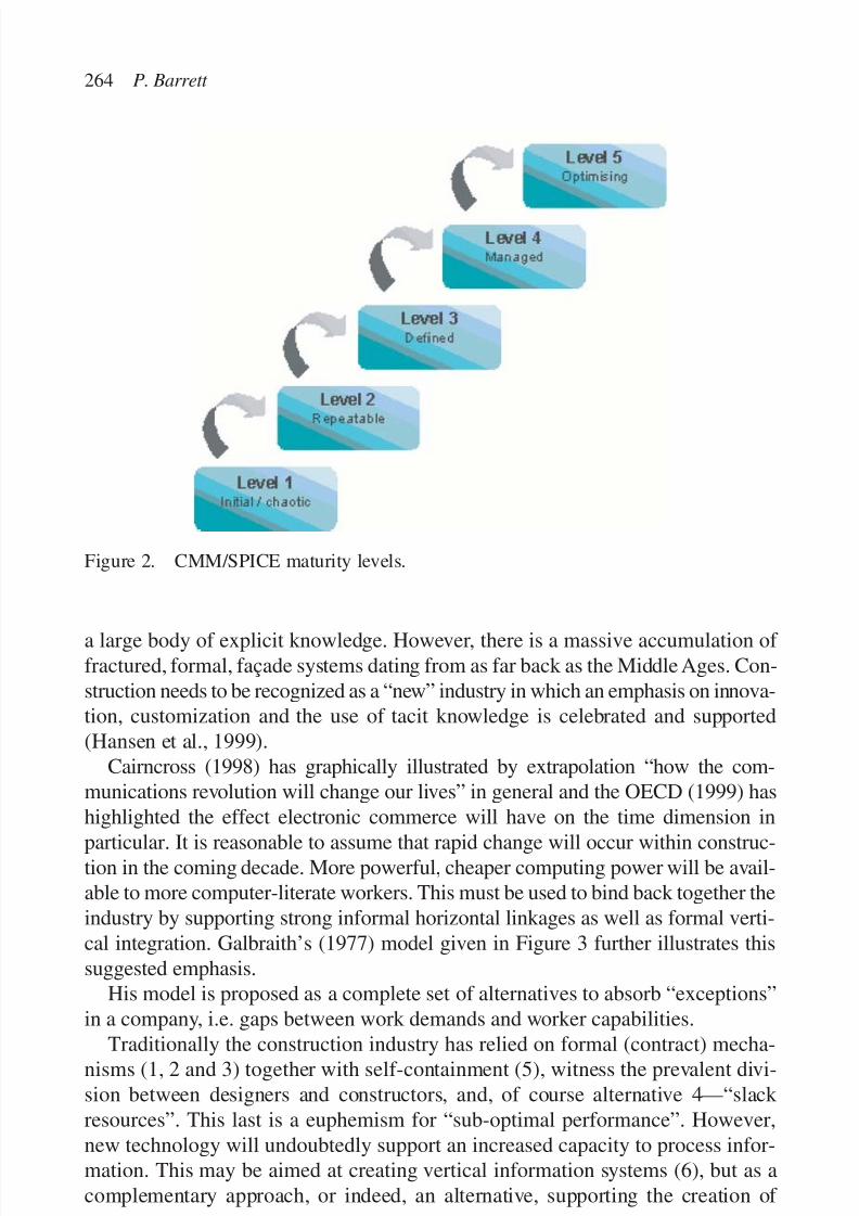
7/14/2019 4DCAD and Visualization in Construction
http://slidepdf.com/reader/full/4dcad-and-visualization-in-construction-56327c6a084e9 273/296
a large body of explicit knowledge. However, there is a massive accumulation of fractured, formal, façade systems dating from as far back as the Middle Ages. Con-struction needs to be recognized as a “new” industry in which an emphasis on innova-tion, customization and the use of tacit knowledge is celebrated and supported(Hansen et al., 1999).
Cairncross (1998) has graphically illustrated by extrapolation “how the com-munications revolution will change our lives” in general and the OECD (1999) hashighlighted the effect electronic commerce will have on the time dimension in
particular. It is reasonable to assume that rapid change will occur within construc-tion in the coming decade. More powerful, cheaper computing power will be avail-able to more computer-literate workers. This must be used to bind back together theindustry by supporting strong informal horizontal linkages as well as formal verti-cal integration. Galbraith’s (1977) model given in Figure 3 further illustrates thissuggested emphasis.
His model is proposed as a complete set of alternatives to absorb “exceptions”in a company, i.e. gaps between work demands and worker capabilities.
Traditionally the construction industry has relied on formal (contract) mecha-nisms (1, 2 and 3) together with self-containment (5), witness the prevalent divi-sion between designers and constructors, and, of course alternative 4—“slack resources”. This last is a euphemism for “sub-optimal performance”. However,new technology will undoubtedly support an increased capacity to process infor-mation. This may be aimed at creating vertical information systems (6), but as acomplementary approach, or indeed, an alternative, supporting the creation of
264 P. Barrett
Figure 2. CMM/SPICE maturity levels.
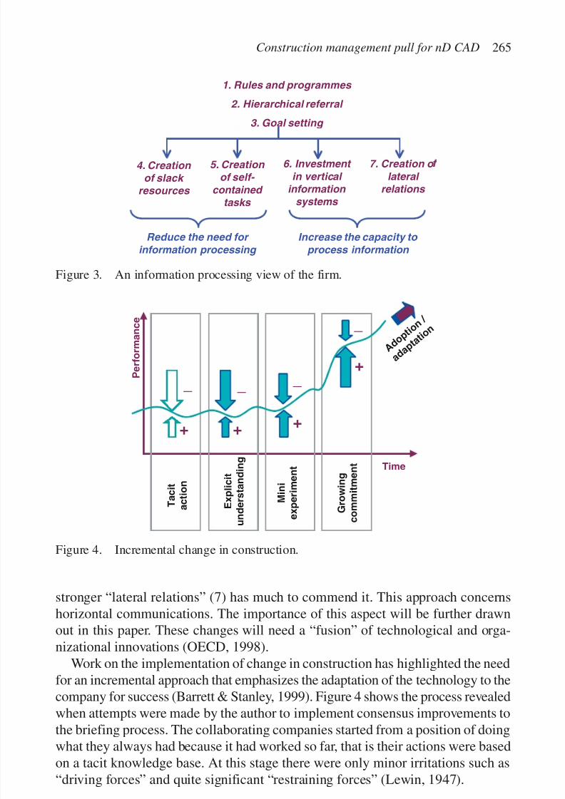
7/14/2019 4DCAD and Visualization in Construction
http://slidepdf.com/reader/full/4dcad-and-visualization-in-construction-56327c6a084e9 274/296
stronger “lateral relations” (7) has much to commend it. This approach concernshorizontal communications. The importance of this aspect will be further drawnout in this paper. These changes will need a “fusion” of technological and orga-nizational innovations (OECD, 1998).
Work on the implementation of change in construction has highlighted the needfor an incremental approach that emphasizes the adaptation of the technology to thecompany for success (Barrett & Stanley, 1999). Figure 4 shows the process revealedwhen attempts were made by the author to implement consensus improvements tothe briefing process. The collaborating companies started from a position of doingwhat they always had because it had worked so far, that is their actions were basedon a tacit knowledge base. At this stage there were only minor irritations such as“driving forces” and quite significant “restraining forces” (Lewin, 1947).
Construction management pull for nD CAD 265
1. Rules and programmes
2. Hierarchical referral
3. Goal setting
4. Creation
of slack
resources
5. Creation
of self-
contained
tasks
Reduce the need for
information processing
6. Investment
in vertical
information
systems
7. Creation o
lateral
relations
Increase the capacity to
process information
Figure 3. An information processing view of the firm.
P e r f o r m a n c e
Time
+
__
+ +
T a c i t
a c t i o n
E x p l i c i t
u n d e r s t a n d i n g
M i n i
e x p e r i m e n t
G r o w i n g
c o m m i t m e n t
A d o p
t i o n
/
a d a p
t a t i o
n
_+
_
Figure 4. Incremental change in construction.

7/14/2019 4DCAD and Visualization in Construction
http://slidepdf.com/reader/full/4dcad-and-visualization-in-construction-56327c6a084e9 275/296
First of all, as we tried to implement the agreed changes together, nothing hap-pened! The firms decided their clients “didn’t want to be guinea pigs” and carried onas before. Even though the researchers were disappointed we had to try to under-
stand this resistance. It became clear that it was based, not so much on antagonismtowards the proposals, which they had all been involved in developing, but rather itwas grounded in a highly rational (from their perspective) aversion to risk. Eachfirm was not acting in a vacuum, they had many relationships with other parts of the industry. If they changed in isolation it could cause real problems of disjuncturein these relationships. Given the current nature of the industry, any resulting problemswould be blamed on our partners. In these conditions a company would have to beeither foolish or brave and highly motivated to move first. Initially our companieswere not sufficiently motivated, but they did see more clearly what was goingwrong and why. This led to the explicit understanding stage shown on the model,i.e. no change in their actions, but a significant change in the companies’ apprecia-tion of the impact of their actions, even as they rushed from incident to incident.
As a consequence of this heightened awareness the companies tended to gainmotivation to change “now that we have seen it go wrong again!” This increasedmotivation led to the design of low risk “mini-experiments” with consequentlyreduced restraining forces. The forms were beginning to move. As these experimentsdelivered some benefits the companies commitment to the implementation of the
ideas grew. The perception of the risks dwindled and the motivation to carry on grew.Further experiments were built in and the ideas progressively adapted and adoptedby the companies. This rather extended description serves to highlight the rockyroad to implementation and so the need for a sustained incremental approach and atolerance (indeed expectation) of a mixture of success and failure on the way. Thisrather uneven progress is reflected very well in the juggling analogy (Gelb & Buzan,1994), where it is stressed that to make progress at all mistakes must be accommo-dated. In litigious construction this means trying things out behind the scenes or on
a limited basis. Trying to pick up three balls in front of an audience and just jugglewithout any practice is likely to have comical results. However, not many construc-tion practitioners want reputations as clowns! So take-up of new systems must allowadoption in stages through non-threatening, low risk, incremental access.
There is very strong resonance between the above view of managing changewithin construction companies and the findings of MIT’s recent study of the pro-cesses of architectural design. This is summed up in the following view: “No processworth replicating is replicable. Put in less jarring terms:A worthwhile process must
be reinvented rather than mechanically reproduced.” (Horgen et al., 1999: 269). Thepoint is that there is no short cut in the adoption of new technologies and integratingthem with a company’s processes. Each firm has to engage in its own tailored learn-ing process. If technology is at the center of this it is still only a part of a much morecomplex whole. And beyond the firm itself and all of its dimensions there is theindustry context to take into account. A firm may choose to move, but on its ownit cannot move very far.
266 P. Barrett
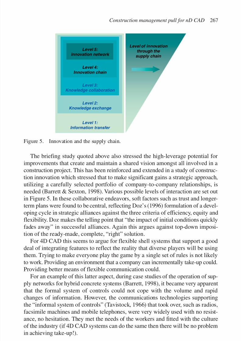
7/14/2019 4DCAD and Visualization in Construction
http://slidepdf.com/reader/full/4dcad-and-visualization-in-construction-56327c6a084e9 276/296
The briefing study quoted above also stressed the high-leverage potential forimprovements that create and maintain a shared vision amongst all involved in aconstruction project. This has been reinforced and extended in a study of construc-
tion innovation which stressed that to make significant gains a strategic approach,utilizing a carefully selected portfolio of company-to-company relationships, isneeded (Barrett & Sexton, 1998). Various possible levels of interaction are set outin Figure 5. In these collaborative endeavors, soft factors such as trust and longer-term plans were found to be central, reflecting Doz’s (1996) formulation of a devel-oping cycle in strategic alliances against the three criteria of efficiency, equity andflexibility. Doz makes the telling point that “the impact of initial conditions quicklyfades away” in successful alliances. Again this argues against top-down imposi-
tion of the ready-made, complete, “right” solution.For 4D CAD this seems to argue for flexible shell systems that support a good
deal of integrating features to reflect the reality that diverse players will be usingthem. Trying to make everyone play the game by a single set of rules is not likelyto work. Providing an environment that a company can incrementally take-up could.Providing better means of flexible communication could.
For an example of this latter aspect, during case studies of the operation of sup-ply networks for hybrid concrete systems (Barrett, 1998), it became very apparent
that the formal system of controls could not cope with the volume and rapidchanges of information. However, the communications technologies supportingthe “informal system of controls” (Tavistock, 1966) that took over, such as radios,facsimile machines and mobile telephones, were very widely used with no resist-ance, no hesitation. They met the needs of the workers and fitted with the cultureof the industry (if 4D CAD systems can do the same then there will be no problemin achieving take-up!).
Construction management pull for nD CAD 267
Level 1:
Information transfer
Level 2:
Knowledge exchange
Level 3:
Knowledge collaboration
Level 4:
Innovation chain
Level 5:
Innovation network
Level of innovation
through the
supply chain
Figure 5. Innovation and the supply chain.
7/14/2019 4DCAD and Visualization in Construction
http://slidepdf.com/reader/full/4dcad-and-visualization-in-construction-56327c6a084e9 277/296
The above observation links well with the analysis by Hansen et al. (1999) of knowledge management in management consultancies. They make the distinctionbetween two principal strategies, namely “codification” or “personalization”. The
aim with the codification approach is to “Provide high quality, reliable, and fastinformation-systems implementation by reusing codified knowledge”. Personal-ization aims to “Provide creative, analytically rigorous advice on high-level strate-gic problems by channeling individual expertise”. (p. 109). Codification assumesa volume of work with a lot of reuse of knowledge by large teams with a lot of
juniors, using people-to-document systems, highly supported by IT. Personalizationassumes high margin work carried out by well-qualified small teams using person-to-person knowledge management, supported by moderate IT systems.
… companies that use knowledge effectively pursue one strategy predomi-nantly and use the second strategy to support the first. We think of this as an80-20 split… Executives who try to excel at both strategies risk failing atboth. (p. 112).
So, they are arguing you have to make a broad choice, but which alternativerelates best to construction? To choose a predominant strategy (codification orpersonalization respectively) depends on whether: the service is standardized orcustomized; the organization/sector mature or innovative; the knowledge used to
solve problems explicit or tacit knowledge. Much of construction is customizedand we have already seen that company systems are of low maturity and the knowl-edge used is predominantly tacit. This all points towards a strategy that emphasizesteams, person-to-person knowledge management and only moderate IT supportwith an emphasis on communications.
It is not possible to generalize, but it seems that construction faces the uncertaintyand, doubtless as a consequence, has many of the characteristics of a new, dynamic,thrusting industry. These characteristics should be celebrated and supported. The
work of Hansen et al. connects with more substantial work specifically focused onconstruction professionals. For example, Coxe et al. (1987) set out a parallel choicebetween “practice-centered businesses” and “business-centered practices”. The greatmajority of design firms are primarily practices and this again fits with the cus-tomization strategy.
This emphasis on communications rather than codification underpins a specu-lative view based on work with the UK concrete industry. This is drawn from casestudy work specific to concrete, but also from an innovation study investigating
supply chains in which the prominent role of materials and components suppliersbecame very evident. Figure 6 sets out the idea of creating a web-based environ-ment to link the various players. In particular, design support is made accessibleto designers and tendering and ordering made easy for contractors and suppliers.Within the shared environment a set of broad generic systems are provided withassociated interactive cost, etc. models. The starting position is shown in thediagram, but over time it is anticipated that consortia and market mechanisms
268 P. Barrett

7/14/2019 4DCAD and Visualization in Construction
http://slidepdf.com/reader/full/4dcad-and-visualization-in-construction-56327c6a084e9 278/296
would evolve the content of the shared space as experience and opportunitiesbecame evident.
The above examples generally relate to studies of large organizations with rela-tively robust in-house management capabilities. So, it is worth mentioning in passingthat a series of benchmarking studies by ConstructIT (1998) of large constructioncompanies has found that there is great variability in the beneficial use of IT systemseven amongst these leading companies. However, the message that non-prescriptive,flexible communications tools are needed is heavily reinforced when the size struc-ture of the industry is considered. Construction is populated mainly by very smallfirms. Although drawing from slightly old data, in the EU for example, about97% of firms, doing 49% of the work are less than 20 employees strong (Atkins,1994; see Table 1 for more detail).
This means that sophisticated bespoke technologies are unlikely to be adoptedby enough players to create sufficient momentum for an industry-wide, top-downchange. This has led construction researchers in the UK towards using standardsoftware platforms where possible, or at least making the interface appear familiar.For example, a database tool used to encourage cross-organizational learning in
Construction management pull for nD CAD 269
Clients /
designers
5 generic Hccstructural
systems
X 5 standard
building layouts
Standardiseddesign details
5 Models of
elemental costs
5 Models of
programmes
Suppliers cost / delivery details
Contractors
/ suppliers
5 Supply chainmodels
Figure 6. A speculative, neutral web-based environment for concrete.
Table 1. Employment and number of construction enterprises in the EU.
Size of firm Number Percentage Number of Percentage of Percentage of (employees) of firms of firms employees employees total turnover
0–9 1,700,797 92.80 3,512,969 43.3 36.110–19 76,618 4.20 1,025,263 12.7 12.420–99 48,695 2.70 1,820,354 22.5 24.7
100–199 3,543 0.20 492,320 6.1 7.2200–499 1,585 0.10 483,257 6.0 7.5500ϩ 585 0.03 761,345 9.4 12.1
All firms 1,831,822 100.00 8,095,509 100.0 100.0

7/14/2019 4DCAD and Visualization in Construction
http://slidepdf.com/reader/full/4dcad-and-visualization-in-construction-56327c6a084e9 279/296
construction (COLA) is available in Microsoft Access, as “smaller organizationsare more likely to have access to the … products and, more importantly, access tothe skills required to adapt and manipulate the database for their own purposes”
(Boam, 1999).
DIMENSIONS OF SYSTEMS
It is usual to speak in project management circles of managing for time, cost andquality. This is really quite a misleading formulation. For example, time and costcan easily be seen as quality dimensions themselves, and, what else is to be includedunder the quality heading anyway? It seems more fruitful to think in terms of generic performance criteria, or at least to use quality as an overall descriptor fora comprehensive set of such criteria. The former “quality-free” approach is advo-cated convincingly by Sjoholt (1989), however, the latter approach was taken in aproject involving the then newly independent states of Estonia and Lithuania,together with Danish and UK partners (CONQUEST, 1995). In this challengingcross-cultural project we strived for an objective assessment of quality in construc-tion. The following list of eight performance dimensions was created: location
(planning), function (fitness for user’s purpose), aesthetics, cost, time, technical per-formance, health and safety and environmental performance. These criteria werefound to be “owned” variously by different selections of stakeholders, ranging fromthe “paying client” to “society at large”, with any control achieved by a range of mechanisms, ranging from socialization through custom, to legislation.
The resulting mapping achieved is summarized in Table 2. Solid squares are theprimary mechanisms and unfilled squares the secondary mechanisms. This table wasdeveloped for a particular comparative analysis, however, the blank sheet stimulus
provided by the new states studied helped the team take an objective view of construction in general. The notion of a range of performance dimensions controlled(managed) using a range of mechanisms in a variety of combinations seems robust.
This incidentally fits with work on the interactions of markets, hierarchies andnetworks, which Bradach & Eccles (1991) typify as underpinned by price, authorityand trust respectively. They claim that these mechanisms are: “overlapping, embed-ded, intertwined, juxtaposed and nested… typically control mechanisms are graftedon to and leveraged off existing social structures”. This seems a realistic view from
our studies of construction. The implication is again that top-down “designed”solutions are unlikely to be capable of reflecting the complexity of reality.Taking this wider range of, say eight, criteria should help to overcome “over-
measurement” of the easily measurable (Etzioni, 1964). It can be seen to lead natu-rally to the idea of a broader perspective beyond the immediate project needs.Construction can in fact be seen to be merely a change agent for the built environ-ment, which itself supports society’s needs (see Fig. 7). That is, although construction
270 P. Barrett
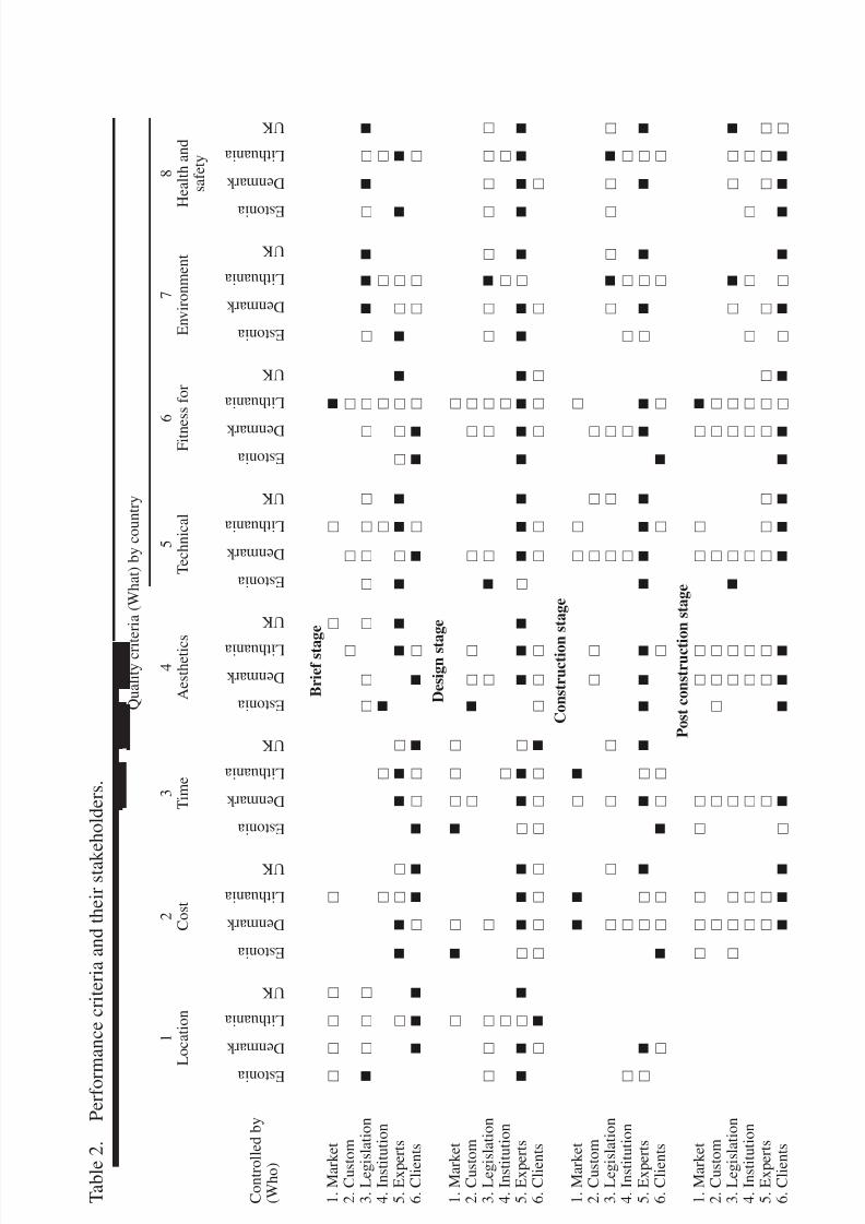
7/14/2019 4DCAD and Visualization in Construction
http://slidepdf.com/reader/full/4dcad-and-visualization-in-construction-56327c6a084e9 280/296
T a b l e 2 .
P e r f o r m a
n c e c r i t e r i a a n d t h e i r s t a k e h o l d e r s .
Q u a l i t y c r i t e r i a ( W h a t ) b y c o u n t r y
1
2
3
4
5
6
7
8
L o
c a t i o n
C o s t
T i m e
A e s t h e t i c s
T e c h n i c a l
F i t n e s s f o r
E n v i r o n m e n t
H e a l t h a n d
s a f e t y
B r i e f s t a g e
1 . M a r k e t
2 . C u s t o m
3 . L e g i s l a t i o n
4 . I n s t i t u t i o n
5 . E x p e r t s
6 . C l i e n t s
D e s i g n s t a g
e
1 . M a r k e t
2 . C u s t o m
3 . L e g i s l a t i o n
4 . I n s t i t u t i o n
5 . E x p e r t s
6 . C l i e n t s
C o n s t r u c t i o n s t a g e
1 . M a r k e t
2 . C u s t o m
3 . L e g i s l a t i o n
4 . I n s t i t u t i o n
5 . E x p e r t s
6 . C l i e n t s
P o s t c o n s t r u c t i o n s t a g e
1 . M a r k e t
2 . C u s t o m
3 . L e g i s l a t i o n
4 . I n s t i t u t i o n
5 . E x p e r t s
6 . C l i e n t s
E s t o n i a
D e n m a r k
L i t h u a n i a
U K
E s t o n i a
D e n m a r k
L i t h u a n i a
U K
E s t o n i a
D e n m a r k
L i t h u a n i a
U K
E s t o n i a
D e n m a r k
L i t h u a n i a
U K
E s t o n i a
D e n m a r k
L i t h u a n i a
U K
E s t o n i a
D e n m a r k
L i t h u a n i a
U K
E s t o n i a
D e n m a r k
L i t h u a n i a
U K
E s t o n i a
D e n m a r k
L i t h u a n i a
U K
C o n t r o l l e d b y
( W h o )

7/14/2019 4DCAD and Visualization in Construction
http://slidepdf.com/reader/full/4dcad-and-visualization-in-construction-56327c6a084e9 281/296
is a very big and important industry, it is a service industry and as such is a means (toa means) to an end, and not an end in itself.
The built environment is there to serve society, which in the UK’s Government’sterms equates to improving competitiveness and quality of life. Construction is the
change agent through which this change is achieved. Thus, at a minimum thewhole project life cycle needs to be addressed and here the “4” in 4D CAD comesinto focus as time is a key linkage to many of these issues. This takes into accounta long-term perspective as well as the project duration highlights issues, such asthe whole life cycle of facilities, including user views, but also societal factorssuch as planning and environmental impacts.
IMPLICATIONS OF MULTI-DIMENSIONALITY
Creating systems that can model, in detail, physical project attributes over time,perhaps even including the variation of construction project costs, is clever, butdoes it address the critical problem areas? Systems like these will probably supportimproved efficiency in design and logistics on site, however, these are not theproblems highlighted in strategic reports on the industry (e.g. Latham, 1994;DETR, 1998). In these reports there is a heavy emphasis on trust and relationships,
as well as some fairly mechanistic thinking. This lag is evident in constructionsupply chain theories to emphasise almost exclusively logistics (O’Brien, 1997),whereas, in the general field of logistics there is an interesting development towardsstudying the softer and longer-term aspects of supply networks, such as percep-tions of requirements and performance and customer satisfaction (Harland, 1996).This appears to be following the burgeoning services literature, but particularlyGrönroos’ (1984) work, which highlighted the “expectation—perception gap”.
272 P. Barrett
Figure 7. Construction as a means to a means to an end.

7/14/2019 4DCAD and Visualization in Construction
http://slidepdf.com/reader/full/4dcad-and-visualization-in-construction-56327c6a084e9 282/296
The complex “gaps” picture given in Figure 8 is, of course, a great simplificationbecause each “customer” is someone else’s “supplier”. But, more than this, supplychains are really supply networks as shown in Figure 9. This was based on a study of a specific project. The difficulty of handling complex, “soft”, interacting data like thisis a big challenge for a 4D CAD system. However, it is a necessary effort if relevant,useful systems are to be created. Interestingly, this move in emphasis is paralleled in
general UK research funding which is shifting away from technical “single loop”research (Argyris & Schon, 1978), on how to do better what we already do, towardssupporting organizational and sociological research on how effectiveness can beenhanced through customer-orientated, knowledge-based innovations (e.g. HMSO,1998). The UK Government is pushing forward on open electronic communicationsin its regulatory role (Cabinet Office, 1999), and this could facilitate and stimulatelinkages right the way through from land survey data, to design, to construction, to
Construction management pull for nD CAD 273
SUPPLIER CUSTOMER
Supplier’sperception ofrequirements
Customer’s
perception ofperformance
Supplier’s
perception ofperformance
Customer’sperception ofrequirements Mismatch 1
M i s m a
t c h 3
M i s m a
t c h 4
Mismatch 2
Figure 8. Harland’s supply chain model.
Figure 9. Example analysis of supply network.
R3
R3
P5
P3
R5
R5
P5
P5
R4
R5
P5
P5Specialist sub-
contractor 1
R4
R5
P4
P5
R3
R5
P5
P5
Designer
ClientR4
R4
P5
P5
R3
R4
P5
P5
Constructionmanager
PackageContractor
Specialist sub-contractor 2
Specialist sub-
contractor 3

7/14/2019 4DCAD and Visualization in Construction
http://slidepdf.com/reader/full/4dcad-and-visualization-in-construction-56327c6a084e9 283/296
274 P. Barrett
F i g u r e 1 0 . E
x a m p l e s o f t d a t a a n a l y s i s ( o f i n n o v a t i o n i n s m a l l c o n s t r u c t i o n f i r m s ) .
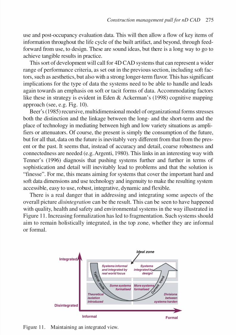
7/14/2019 4DCAD and Visualization in Construction
http://slidepdf.com/reader/full/4dcad-and-visualization-in-construction-56327c6a084e9 284/296
use and post-occupancy evaluation data. This will then allow a flow of key items of information throughout the life cycle of the built artifact, and beyond, through feed-forward from use, to design. These are sound ideas, but there is a long way to go to
achieve tangible results in practice.This sort of development will call for 4D CAD systems that can represent a widerrange of performance criteria, as set out in the previous section, including soft fac-tors, such as aesthetics, but also with a strong longer-term flavor. This has significantimplications for the type of data the systems need to be able to handle and leadsagain towards an emphasis on soft or tacit forms of data. Accommodating factorslike these in strategy is evident in Eden & Ackerman’s (1998) cognitive mappingapproach (see, e.g. Fig. 10).
Beer’s (1985) recursive, multidimensional model of organizational forms stressesboth the distinction and the linkage between the long- and the short-term and theplace of technology in mediating between high and low variety situations as ampli-fiers or attenuators. Of course, the present is simply the consumption of the future,but for all that, data on the future is inevitably very different from that from the pres-ent or the past. It seems that, instead of accuracy and detail, coarse robustness andconnectedness are needed (e.g. Argenti, 1980). This links in an interesting way withTenner’s (1996) diagnosis that pushing systems further and further in terms of sophistication and detail will inevitably lead to problems and that the solution is
“finesse”. For me, this means aiming for systems that cover the important hard andsoft data dimensions and use technology and ingenuity to make the resulting systemaccessible, easy to use, robust, integrative, dynamic and flexible.
There is a real danger that in addressing and integrating some aspects of theoverall picture disintegration can be the result. This can be seen to have happenedwith quality, health and safety and environmental systems in the way illustrated inFigure 11. Increasing formalization has led to fragmentation. Such systems shouldaim to remain holistically integrated, in the top zone, whether they are informal
or formal.
Construction management pull for nD CAD 275
Integrated
Disintegrated
Informal Formal
Systems informal and integrated by real world focus
Some systems
formalised
Theoretical isolation introduced
More systems
formalised
Divisions between
systems harden
Systems integrated by
design! T y p
i c a l r o
u
t e
C u r r e
n t
t r e n d
Ideal zone
Figure 11. Maintaining an integrated view.

7/14/2019 4DCAD and Visualization in Construction
http://slidepdf.com/reader/full/4dcad-and-visualization-in-construction-56327c6a084e9 285/296
In terms of traditional logic the argument is for extension over connotation.Assuming a finite capacity for a system it is argued that it is better to include allof the important dimensions that need to be integrated, but as a consequence the
volume of detail will have to be sacrificed. This approach will, in addition, reducethe denseness of the system to new users and so make it more accessible and trans-parent.
Concentrating on effectiveness should also lead to tools that emphasize thecommunications aspect and exploit widely available, increasingly familiar tech-nologies, such as the web. This will leave the industry to deal with the minutiae of the process, but within a informing context in which the major short- and long-termperformance criteria of the full range of stakeholders is given center stage. Thiscan be seen as a holographic approach (Morgan & Ramirez, 1983), with the majorperformance criteria being reflected at various levels and time-frames for differentstakeholders with, in each case, an appropriate level of detail.
CONCLUSION
Underlying a lot of this discussion has been the distinction between hard and soft
data, which parallels to a degree the distinction between explicit and tacit infor-mation. Figure 12 (based on Nonaka & Takeuchi, 1995) uses this classificationand endeavors to summarize the suggested shift in 4D CAD. If the tacit –tacit
emphasis of the industry is taken as a given, then the mismatch with the explicit –explicit character of 4D CAD systems is stark. For the industry to operate to itsoptimum the synergies of all four modes of knowledge conversion are needed
276 P. Barrett
Figure 12. Modes of knowledge conversion.

7/14/2019 4DCAD and Visualization in Construction
http://slidepdf.com/reader/full/4dcad-and-visualization-in-construction-56327c6a084e9 286/296
(Barrett & Sexton, 1999). The implication is that 4D CAD systems need to shiftemphasis towards the tacit –explicit mode by accommodating a wider than normalrange of key hard and soft, long- and short-term performance criteria (nD CAD)
at a coarse, but robust level of resolution. In parallel with this a push towards sup-porting explicit –tacit knowledge conversion is needed with an emphasis on richercommunications.
The developments suggested will create a closer fit between systems’ characteris-tics and the reality experienced by those in the industry. As such it will simply makemore sense for such systems to be taken up through industry pull, especially if anincremental, but progressive trajectory is supported. Thus, building from simple,but useful implementations, based on “loose couplings” (Baumard, 1999), evolutioncan take place as the general systems and processes in industry improve. Moresophisticated modular applications can then be built into the robust performance-orientated framework and communications infrastructure created. Progressively,greater and more widely available computer power will doubtless be available, butinitially any capability should be used to make systems as easy and flexible as pos-sible to use, with particular attention on ease of data exchange between companies.
CAD is an important tool for the journey from idea to artifact implicit in everyconstruction project. Based on the above analysis the following keywords fordevelopments in 4D CAD are suggested from a “construction management pull”
perspective, namely: outwards-looking, multi-perspective, hard and soft data pro-cessing, coarse, robust, strategically-directed, open, informing, integrative, commu-nications orientated, evolutionary and intuitive. nD CAD systems that succeed inthe future will provide a rich, broad and integrated knowledge context to the tacit–
tacit essence of the construction industry. As such they could be termed wisdom-based systems!
REFERENCES
Aalami, F. & Fischer, M. 1998. Joint product and process model elaboration based on con-struction method models. The life cycle of construction innovations. CIB Publication226.
Argenti, J. 1980. Practical corporate planning. Allen and Unwin.Argyris, C. & Schon, D. 1978. Organisational learning: a theory of action perspective.
Addison-Wesley.
Atkins, W.S. 1994. Strategies for the European construction sector . Luxembourg: EC.Barrett, P.S. 1998. Hybrid concrete structures for the UK market: business processes and desirable process improvements. Reading: Reinforced Concrete Council.
Barrett, P.S. & Sexton, M. 1998. Integrating to innovate. London: Construction IndustryCouncil.
Barrett, P.S. & Sexton, M. 1999. The transformation of ‘out-of-industry’knowledge into con-struction industry wisdom. Report to the CRISP Motivation Theme Group, London.
Barrett, P.S. & Stanley, C. 1999. Better construction briefing. Oxford: Blackwell Science.
Construction management pull for nD CAD 277
7/14/2019 4DCAD and Visualization in Construction
http://slidepdf.com/reader/full/4dcad-and-visualization-in-construction-56327c6a084e9 287/296
Barrett, P.S. & Stave, O. 1993. Integrated project planning using CAD: a case study.Proceedings of the 7th CIB W-65 international symposium, University of the West Indies.
Baumard, P. 1999. Tacit knowledge in organisations. London: Sage.Beer, S. 1985. Diagnosing the system for organisations. Chichester: John Wiley.
Boam, J. 1999. COLA user manual. Leeds Metropolitan University, UK. For details of theCOLA system see (24 September 1999), http://is.lse.ac-uk/b-hive
Bradach, J.L. & Eccles, R.G. 1991. Price, authority and trust. In Thompson et al. (eds), Markets, hierarchies and networks: 277–292. London: Sage.
Cabinet Office. 1999. Modernising government. London: Cm 4310.Cairncross, F. 1998. The death of distance. London: Orien Business Books.CONQUEST. 1995. Achieving quality in construction. EC PHARE-ACE Final Report,
Salford.ConstructIT. 1998. Benchmarking best practice reports: supplier management and project
programming and control. Construct IT, University of Salford.Coxe,W. et al. 1987. Success strategies for the design professional. New York: McGraw-Hill.DETR. 1998. Rethinking construction. The Egan Report, DETR, London, (16 July 1998).
www.construction.detr.gov.uk Doz, Y.L. 1996. The evolution of cooperation in strategic alliances: initial conditions or
learning processes? Strategic Management Journal 17: 55–83.Eden, C. & Ackerman, F. 1998. Making strategy. London: Sage.Etzioni, A. 1964. Modern organizations. Englewood Cliffs, NJ: Prentice-Hall.Galbraith, J.R. 1977. Organisation design. Reading, Mass: Addison-Wesley.Gelb, M.J. & Buzan, T. 1994. Lessons from the art of juggling. London: Aurum Press.
Grönroos, C. 1984. Strategic management and marketing in the service sector. Bromley:Chartwell-Bratt.HMSO. 1998. Our competitive future: building the knowledge driven economy. Cm 4176,
London.Hansen, M.T., Nohria, N. & Tierney, T. 1999. What’s your strategy for managing knowl-
edge. Harvard Business Review March–April: 106–116.Harland, C.M. 1996. Supply chain management: relationships, chains and networks.
British Journal of Management 7(special issue): S63–S80.Hersey, P., Blanchard, K.H. & Johnson, D.E. 1996. Managing organisational behaviour:
utilizing human resources, 7th edition. New Jersey: Prentice-Hall.
Horgen, T.H., Joroff, M.L. & Schon, D.A. 1999. Excellence by design: transformingworkplace and work practice. New York: John Wiley and Sons Ltd.
Huff, A.S. 1982. Industry influences on strategy reformation. Strategic Management Journal 3: 119–131.
Latham, M. 1994. Constructing the team. The Latham Report, London: HMSO.Leavitt, Dill & Eyring. 1973. The organizational world. New York: Harcourt Brace
Javanovich.Lewin, K. 1947. Frontiers in group dynamics. Human Relations I(1): 5–41.Morgan, G. & Ramirez, R. 1983. Action learning: a holographic metaphor for guiding
social change. Human Relations 37(1): 1–28.
Nonaka, I. & Takeuchi, H. 1995. The knowledge creating company: how Japanese compa-nies create the dynamics of innovation. New York: Oxford University Press.
OECD. 1998. 21st century technologies: promises and perils of a dynamic future. OECD.OECD. 1999. The economic and social impact of electronic commerce. OECD.O’Brien, W.J. 1997. Construction supply-chains: case study, integrated cost and perform-
ance analysis. In L. Alarcon (ed.), Lean construction: 187–222. Rotterdam: A.A.Balkema.
278 P. Barrett

7/14/2019 4DCAD and Visualization in Construction
http://slidepdf.com/reader/full/4dcad-and-visualization-in-construction-56327c6a084e9 288/296
SEI. 1994. The capability maturity model. SEI, Addison Wesley Longman Inc.Sarshar, M., Haigh, R., Finnemore, M., Barrett, P. & Aouad, G. 1999. Standardised process
improvement for construction enterprises: an EU update. International conference ontechnology watch and innovation in the construction industry, Brussels, April 2000
(submitted).Sjoholt, O. 1989. From quality assurance to improvement management . Oslo: NBI.Spender, J.C. 1989. Industry recipes: the nature and sources of management judgement .
Oxford: Basil Blackwell.Tavistock. 1966. Interdependence and uncertainty: a study of the building industry. London:
Tavistock Institute.Tenner, E. 1996. Why things bite back: new technology and the revenge effect . London:
Fourth Estate.
Construction management pull for nD CAD 279

7/14/2019 4DCAD and Visualization in Construction
http://slidepdf.com/reader/full/4dcad-and-visualization-in-construction-56327c6a084e9 289/296
7/14/2019 4DCAD and Visualization in Construction
http://slidepdf.com/reader/full/4dcad-and-visualization-in-construction-56327c6a084e9 290/296
CLOSURE
R.R.A. Issa, I. Flood, W.J. O’Brien
M.E. Rinker, Sr. School of Building Construction,
University of Florida, Gainesville, FL, USA
281
CURRENT STATE OF 4D CAD
3D/4D CAD tools are in their second decade of use in the design and constructionindustry. From scattered early efforts in the late 1980s, the 1990s saw a prolifer-
ation of such tools in practice. Certain industries such as industrial constructionnow routinely design projects in 3D. In other areas, such as general building con-struction, there are owners, architects, contractors, subcontractors and vendorsthat have taken the lead in applying 3D/4D tools across their operations. Ownersrequire 3D for design communication and decision-making and use the models forfacilities management. Architects use 3D models to communicate with clients,render dramatic sculptural forms, and share these models with contractors andsubcontractors to enable construction of these sculptural forms. Contractors use
3D models for coordination of building systems and materials procurement.Contractors use 4D models to ensure schedules are buildable and for trade coordi-nation. Subcontractors use 3D and 4D tools for much the same purposes as con-tractors, but often use more detailed models to plan field production. Manyvendors have developed 3D models of their offerings to allow architects and engi-neers to place them directly into their designs. Vendors also use 3D models todirect their internal production processes.
The 1990s also saw increased sophistication in software packages. At the highend, tools have grown more powerful in storing intelligence about building objectsand their relationships (e.g. an object is a beam connected to a column; the beamhas attributes of strength, material properties, a manufacturer and tracking num-ber, etc.). An infrastructure of tools has been developed to support implementationof 3D/4D models. These tools include: libraries, global positioning systems for sur-veying linked to the 3D model objects, portable display devices, and data exchangestandards. Collectively, these developments make possible the integrated application
7/14/2019 4DCAD and Visualization in Construction
http://slidepdf.com/reader/full/4dcad-and-visualization-in-construction-56327c6a084e9 291/296
of 4D analysis across all stages of the project lifecycle (although an integrated off-the-shelf package does not yet exist, requiring investment on the part of projectteam members). Advanced software applications promising more integrated func-
tionality are in the commercial product development pipeline.Mid- and lower-level software applications have also seen increasing sophisti-cation in their ability to manipulate 3D models. Mainstream commercial CADpackages now allow users to rapidly develop 3D models at different levels of detail. It is also possible to perform 4D analysis by linking the 3D models toscheduling packages and/or by manipulating the 3D objects using layer functions.3D technology has also enhanced lower-end CAD systems, perhaps best evincedby the sub-US$100 home design CAD packages sold in retail stores. These sys-tems allow homeowners to rapidly build and render 3D models of their homes,producing drawings usable by contractors. Cost and capability are no longer con-sidered a barrier for any firm that wishes to employ 3D/4D tools.
Despite the power and availability of 3D/4D tools, their use is still not commonin most areas of design and construction. Apart from modeling of piping andrelated systems in large-scale industrial construction, the most common use of 3Dmodels is in marketing and conceptual design. Clients are sold on the buildingconcept in 3D “walk-thrus.” Sometimes these 3D concept models have a 4D ele-ment to portray the impact of construction on existing sites or to portray stages of
project development. These models have little detail, and are seldom furtherdeveloped through detailed design or for construction planning. This unfortunatecircumstance is not solely the fault of uncreative practitioners. Further develop-ment in at least four technical and business areas is needed to fully realize thepotential of 4D CAD on practice.
FUTURE STEPS—FOUR AREAS OF DEVELOPMENT TO TAKE
4D TOOLS TO THE NEXT LEVEL
1. The visual interface: There are two related problems with the interface of current tools. First, the more sophisticated tools (and many of the lower-end tools)are difficult to use. The models cannot easily be manipulated by anyone other thanexperts, and simpler representations (e.g. static models including printouts) losemuch of the power of full models. Difficult-to-use software also limits the ability
of users to add information to the model, consequently restricting the model’s use-fulness. Second, it is difficult to customize visualization of the 3D/4D models andrelated data. Every user will have a different set of needs for information and dif-ferent preferences for visualization of that information. Even the most sophisti-cated of existing applications have limited abilities to display information invarious forms. Hence, even if an integrated 4D model is available, the model maynot support business decisions beyond its ability to display information. 4D tools
282 R.R.A. Issa et al.
7/14/2019 4DCAD and Visualization in Construction
http://slidepdf.com/reader/full/4dcad-and-visualization-in-construction-56327c6a084e9 292/296
are by nature information rich. Improved ease of use in accessing and contributinginformation and greater fluidity in customizing the presentation of that informa-tion are necessary developments if 4D models are to be fully leveraged.
2. Data exchange between applications: Improvements in the visual interfacerequire seamless exchange of data among the software applications behind theinterface. Currently, code must be written for each link between applications. Thisis a lengthy and difficult set-up process that most projects are unwilling to support.While writing code on a per-project basis does allow customization, the approachis not scalable. Nor is the customization necessarily fluid; as project needs andproject participants change, it is unclear that the code can be easily adapted tomeet those changes. What is needed is theory and methodology about the sharingof information that supports implementation on projects without detailed codingby experts. Currently, standardized data models are under development to allowsoftware applications to share data. These data models provide a basis for sharingdata such as Ͻschedule activityϾ . It is less clear that these data models willdirectly support higher level reasoning, particularly with regard to user level cus-tomization of information representation. Further developments in sharing andmanipulating data are required for widespread use of 4D tools.
3. Job design to leverage the tools: While there does not currently exist a recipefor collaboration to make best use of 4D tools, it is clear from the existing imple-
mentations that the technology requires new ways of working together. Theserange from the simple changes of design review with a 3D model to the moresophisticated questions of who contributes what to the 3D/4D model. How jobdesign and responsibilities should change is a fundamental issue with implicationsfor firm and project organization, legal responsibilities, and, not least, contractualincentives. Many of the projects that have used 3D/4D models collaborativelyacross firms have done so in the spirit of experimentation. Thus, they have notaddressed the issues of standard operating procedures using the new technologies.
What these procedures should be is very much a subject for future research anddevelopment.
4. Benefits and contracts for 4D: Closely related to the idea of job and organi-zation design is the appropriation of benefits using a 3D/4D environment. Whilemany of the firms using 3D/4D tools report benefits in a wide variety of applica-tions that they believe easily outweighs the cost of 3D/4D model development,only limited cost-benefit analysis has been performed. It is clear that early devel-opment of the model in the project lifecycle pays dividends later in the lifecycle.
However, given the fragmented nature of the construction industry, many of theearly developers of design are not responsible for later stages of the project and donot accrue the benefits from savings in those later stages. In any phase of the proj-ect, it is the rare firm that wishes to absorb the cost of model development withouta clear understanding of the benefits and how they will be distributed. As it isdifficult to predict where benefits will be realized (e.g. on one project in designcoordination, on another project in productivity improvement), it is unclear how to
Closure 283
7/14/2019 4DCAD and Visualization in Construction
http://slidepdf.com/reader/full/4dcad-and-visualization-in-construction-56327c6a084e9 293/296
assemble contracts that appropriately reward those firms that bore the cost of developing a 3D/4D model.
The construction industry has a poor record of consistently supporting
improved planning processes, and 3D/4D tools may not be different from otherapproaches. How to structure contracts to support the use of 3D/4D tools isunclear. Three approaches come to mind: first, the owner can simply pay for themodels and assume that they will get their fair share of benefits. Some owners aretaking this approach. Second, individuals in the industry can adopt the tools andcreate new forms of firms that simply do everything better than traditional firms.These “category killer” firms have redefined other industries and may do so indesign and construction. Third, the tools can become so powerful and cost effec-tive that they replace existing 2D tools and methods in the various firms involvedin the project process. Thus, 3D/4D tools may organically replace 2D work prac-tices. We have seen developments in each of these approaches. However, howthese benefits are supported by contractual structures remains an open question.
So where do we stand on the use of 4D in construction? The 1990s saw the pre-mature proclamation of a coming revolution in practice based on the early bene-fits and tools seen in the late 1980s. Now early in the first decade of themillennium, we are hesitant to make sweeping claims. But we do have the experi-
ence of the 1990s to guide us, and concrete benefits have been seen in practice.The contents of this workshop have established a roadmap to move forward, andthe editors tentatively suggest that at the end of the next decade we will be writingnot about novel developments in 4D tools, but about incremental improvements ina technology that is well accepted.
284 R.R.A. Issa et al.
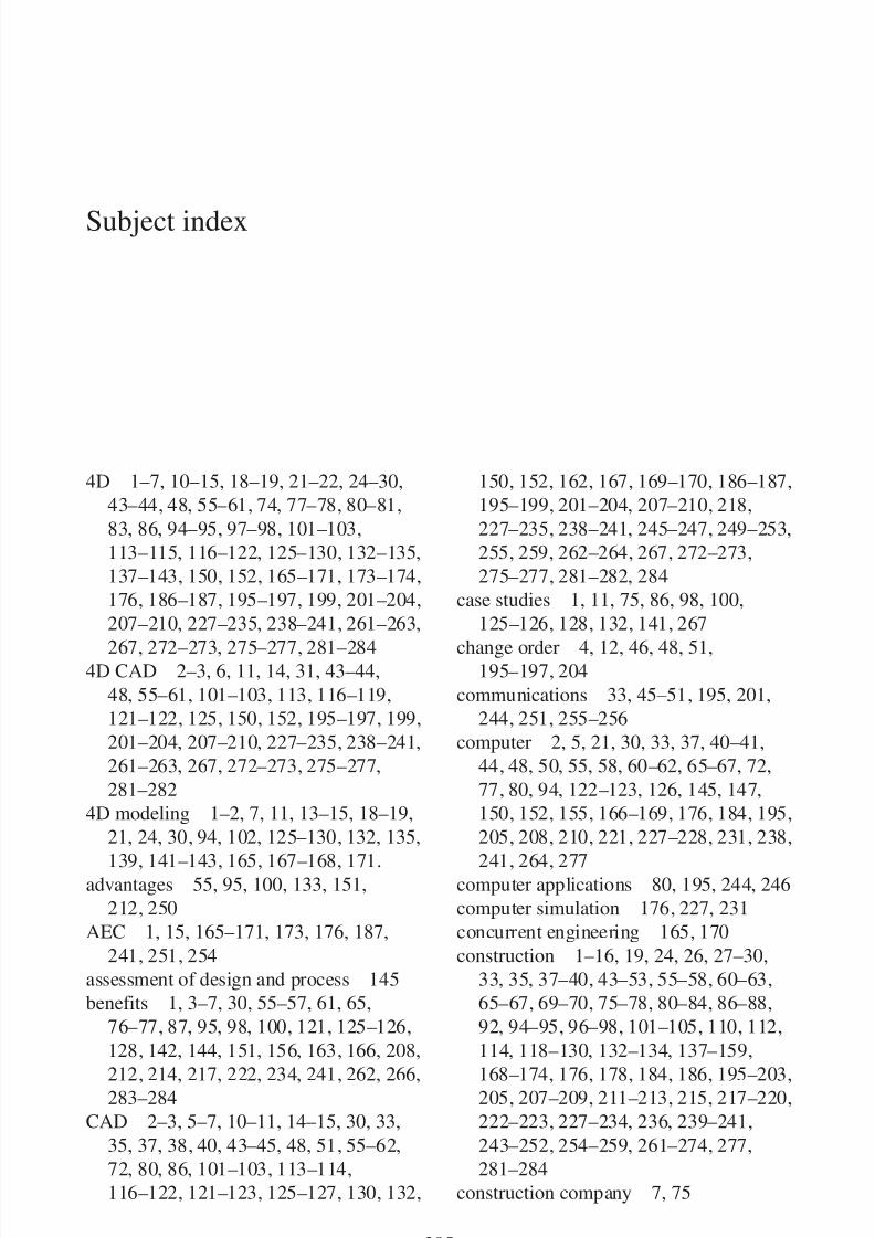
7/14/2019 4DCAD and Visualization in Construction
http://slidepdf.com/reader/full/4dcad-and-visualization-in-construction-56327c6a084e9 294/296
Subject index
285
4D 1–7, 10–15, 18–19, 21–22, 24–30,
43–44, 48, 55–61, 74, 77–78, 80–81,
83, 86, 94–95, 97–98, 101–103,
113–115, 116–122, 125–130, 132–135,
137–143, 150, 152, 165–171, 173–174,
176, 186–187, 195–197, 199, 201–204,
207–210, 227–235, 238–241, 261–263,
267, 272–273, 275–277, 281–284
4D CAD 2–3, 6, 11, 14, 31, 43–44,
48, 55–61, 101–103, 113, 116–119,
121–122, 125, 150, 152, 195–197, 199,
201–204, 207–210, 227–235, 238–241,
261–263, 267, 272–273, 275–277,
281–282
4D modeling 1–2, 7, 11, 13–15, 18–19,
21, 24, 30, 94, 102, 125–130, 132, 135,
139, 141–143, 165, 167–168, 171.
advantages 55, 95, 100, 133, 151,
212, 250
AEC 1, 15, 165–171, 173, 176, 187,
241, 251, 254
assessment of design and process 145
benefits 1, 3–7, 30, 55–57, 61, 65,
76–77, 87, 95, 98, 100, 121, 125–126,
128, 142, 144, 151, 156, 163, 166, 208,
212, 214, 217, 222, 234, 241, 262, 266,
283–284
CAD 2–3, 5–7, 10–11, 14–15, 30, 33,
35, 37, 38, 40, 43–45, 48, 51, 55–62,
72, 80, 86, 101–103, 113–114,
116–122, 121–123, 125–127, 130, 132,
150, 152, 162, 167, 169–170, 186–187,
195–199, 201–204, 207–210, 218,
227–235, 238–241, 245–247, 249–253,
255, 259, 262–264, 267, 272–273,
275–277, 281–282, 284
case studies 1, 11, 75, 86, 98, 100,
125–126, 128, 132, 141, 267
change order 4, 12, 46, 48, 51,
195–197, 204
communications 33, 45–51, 195, 201,
244, 251, 255–256
computer 2, 5, 21, 30, 33, 37, 40–41,
44, 48, 50, 55, 58, 60–62, 65–67, 72,
77, 80, 94, 122–123, 126, 145, 147,
150, 152, 155, 166–169, 176, 184, 195,
205, 208, 210, 221, 227–228, 231, 238,
241, 264, 277
computer applications 80, 195, 244, 246
computer simulation 176, 227, 231
concurrent engineering 165, 170
construction 1–16, 19, 24, 26, 27–30,
33, 35, 37–40, 43–53, 55–58, 60–63,
65–67, 69–70, 75–78, 80–84, 86–88,
92, 94–95, 96–98, 101–105, 110, 112,
114, 118–130, 132–134, 137–159,
168–174, 176, 178, 184, 186, 195–203,
205, 207–209, 211–213, 215, 217–220,
222–223, 227–234, 236, 239–241,
243–252, 254–259, 261–274, 277,
281–284
construction company 7, 75
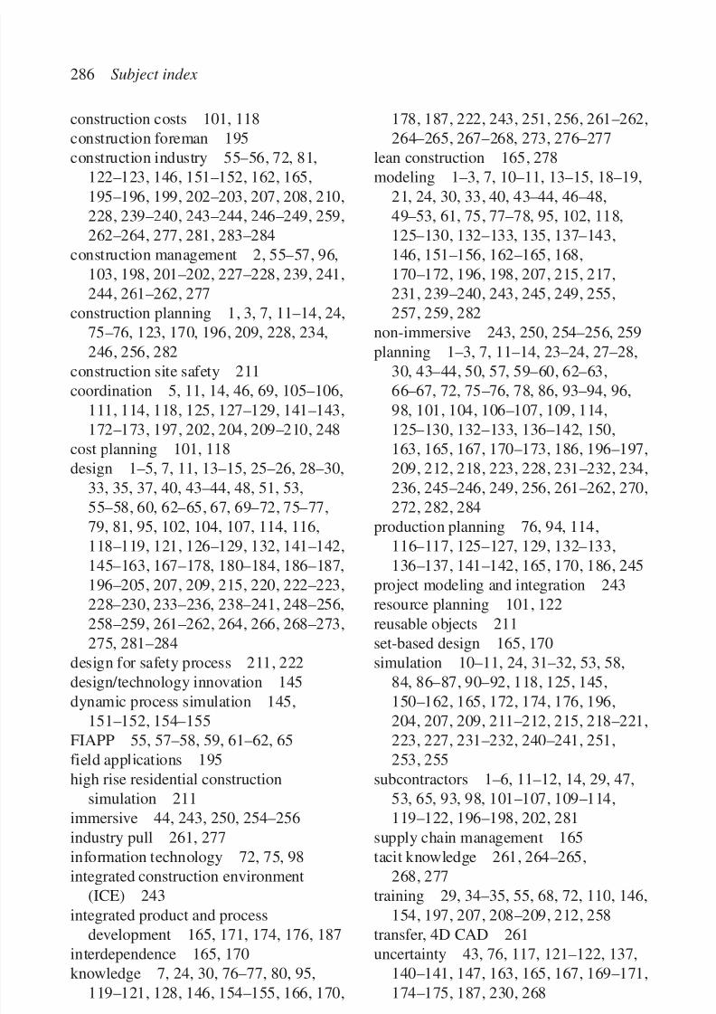
7/14/2019 4DCAD and Visualization in Construction
http://slidepdf.com/reader/full/4dcad-and-visualization-in-construction-56327c6a084e9 295/296
construction costs 101, 118
construction foreman 195
construction industry 55–56, 72, 81,
122–123, 146, 151–152, 162, 165,
195–196, 199, 202–203, 207, 208, 210,
228, 239–240, 243–244, 246–249, 259,
262–264, 277, 281, 283–284
construction management 2, 55–57, 96,
103, 198, 201–202, 227–228, 239, 241,
244, 261–262, 277
construction planning 1, 3, 7, 11–14, 24,
75–76, 123, 170, 196, 209, 228, 234,
246, 256, 282
construction site safety 211
coordination 5, 11, 14, 46, 69, 105–106,
111, 114, 118, 125, 127–129, 141–143,
172–173, 197, 202, 204, 209–210, 248
cost planning 101, 118
design 1–5, 7, 11, 13–15, 25–26, 28–30,
33, 35, 37, 40, 43–44, 48, 51, 53,
55–58, 60, 62–65, 67, 69–72, 75–77,
79, 81, 95, 102, 104, 107, 114, 116,
118–119, 121, 126–129, 132, 141–142,
145–163, 167–178, 180–184, 186–187,
196–205, 207, 209, 215, 220, 222–223,
228–230, 233–236, 238–241, 248–256,
258–259, 261–262, 264, 266, 268–273,
275, 281–284
design for safety process 211, 222
design/technology innovation 145
dynamic process simulation 145,
151–152, 154–155
FIAPP 55, 57–58, 59, 61–62, 65
field applications 195
high rise residential construction
simulation 211
immersive 44, 243, 250, 254–256
industry pull 261, 277
information technology 72, 75, 98
integrated construction environment
(ICE) 243
integrated product and process
development 165, 171, 174, 176, 187
interdependence 165, 170
knowledge 7, 24, 30, 76–77, 80, 95,
119–121, 128, 146, 154–155, 166, 170,
178, 187, 222, 243, 251, 256, 261–262,
264–265, 267–268, 273, 276–277
lean construction 165, 278
modeling 1–3, 7, 10–11, 13–15, 18–19,
21, 24, 30, 33, 40, 43–44, 46–48,
49–53, 61, 75, 77–78, 95, 102, 118,
125–130, 132–133, 135, 137–143,
146, 151–156, 162–165, 168,
170–172, 196, 198, 207, 215, 217,
231, 239–240, 243, 245, 249, 255,
257, 259, 282
non-immersive 243, 250, 254–256, 259
planning 1–3, 7, 11–14, 23–24, 27–28,
30, 43–44, 50, 57, 59–60, 62–63,
66–67, 72, 75–76, 78, 86, 93–94, 96,
98, 101, 104, 106–107, 109, 114,
125–130, 132–133, 136–142, 150,
163, 165, 167, 170–173, 186, 196–197,
209, 212, 218, 223, 228, 231–232, 234,
236, 245–246, 249, 256, 261–262, 270,
272, 282, 284
production planning 76, 94, 114,
116–117, 125–127, 129, 132–133,
136–137, 141–142, 165, 170, 186, 245
project modeling and integration 243
resource planning 101, 122
reusable objects 211
set-based design 165, 170
simulation 10–11, 24, 31–32, 53, 58,
84, 86–87, 90–92, 118, 125, 145,
150–162, 165, 172, 174, 176, 196,
204, 207, 209, 211–212, 215, 218–221,
223, 227, 231–232, 240–241, 251,
253, 255
subcontractors 1–6, 11–12, 14, 29, 47,
53, 65, 93, 98, 101–107, 109–114,
119–122, 196–198, 202, 281
supply chain management 165
tacit knowledge 261, 264–265,
268, 277
training 29, 34–35, 55, 68, 72, 110, 146,
154, 197, 207, 208–209, 212, 258
transfer, 4D CAD 261
uncertainty 43, 76, 117, 121–122, 137,
140–141, 147, 163, 165, 167, 169–171,
174–175, 187, 230, 268
286 Subject index

7/14/2019 4DCAD and Visualization in Construction
http://slidepdf.com/reader/full/4dcad-and-visualization-in-construction-56327c6a084e9 296/296
Subject index 287