4dlighting dimming
TRANSCRIPT

418
Dimming Possibilities
Remote control gives freedomThe right lighting scene or light level can be easily set using a remote control. Even individual control of channels is possible. Naturally all lighting can be swit-ched on and off with the remote control. Remote control functions via radio waves more commonly with infrared light. There are also systems available on the market that only switch the lighting on and off. The DALI-system can be pro-grammed with a remote control, but for larger systems program-ming from a PC with appropriate software is preferable.
Constant light level Many of Fagerhult’s luminaire models can be fitted with a light sensor. Using the sensor, the level of artificial light is adjusted according to the daylight. An increase in daylight turns down the artificial lighting, which saves energy. This means the illumi-nance on the working surface can be maintained at a constant level irrespective of the time of day. Sensor operation varies a little between different manu-facturers. More advanced sensors also offer more functionality such as occupancy detection and IR-receiver.
Dividing into channels Today’s modern light control systems permit several lumin-aire groups or channels to be controlled centrally from one or more places. Using a traditional control unit, such as a dimmer integrated in a pattress box, all luminaires connected to the same channel are regulated. This is known as 1-channel control. With more advanced systems dif-ferent channels can be embraced and controlled individually or together.
GlossaryDimming Variable regulation of the lumi-nous intensity. Light control System that controls individual luminaire groups and/or complete systems HF-ballast for dimming Control gear that via a separate control circuit allows dimming. Digital light control Control signals between the units are transferred in the form of digital commands. Commands in digital form are less sensitive to disturbances than analogue systems. Analogue control Analogue systems are usually based on 1-10V DC between the controller and luminaire. The sys-tem either regulates the voltage or resistance in the control circuit. The length of the control conduc-tor can affect the control result.Phase control (impulse)A system based on control of the lighting level via 240V (for example, with the help of a momentary wall switch or with an integrated pull cord switch in the luminaire). Known best as SwitchDIM. The system requires 4 conductors to the luminaire if a wall switch is used. Addressed control The units in the system can be individually addressed enabling them to be controlled indepen-dently of each other. The digital DALI protocol is addressable.Multi-channel controlAn installation can be divided into different groups, channels, which can be controlled independent of each other or together.Lighting scenes A pre-selected lighting effect/arrangement that can be easily recalled if necessary. Constant light level The system attempts to maintain the luminous intensity within the required area (for example, under the luminaire) at a constant level. The level of the artificial lighting is affected by the incident day-light. Used to save energy.Occupancy detector A detector that senses an individual’s thermal radiation. A movement within the detector’s supervised area switches on the luminaire. An integrated timer switches off the luminaire if no movement is detected within the sensor’s supervised area.IR-receiver Receives the remote control’s signals and transfers these to the system. Usually integrated in a wall panel or multisensor. Multisensor Sensor that usually includes the functions constant light level, oc-cupancy detector and IR-receiver.
Why is it important to be able to control the lighting installation?Modern lighting control systems can improve the quality of the lighting as well as the comfort. Using dimmable luminaires means the lighting is targeted in the right place, at the right time and at the right intensity. In combination with light sensors daylight can be utilised which saves energy. In many buildings the lighting requirement changes several times during the course of a day. The application of light control is therefore an important factor in areas such as, conference rooms and restaurants. An installation with pre-programmed lighting levels, lighting scenes, together with a remote control allows the lighting systems in these types of premises to be utilised to the full.
Lighting scenes Light control systems also offer the possibility to save preselected lighting scenes. These scenes can either be divided up on a channel level or in combina-tion with a master system that controls all the channels in the system. The required lighting scenes are selected via wall panels or remote controls, and the system automatically sets the preselected lighting level for each lighting group. Technical limitations
Some systems for light control re-quire separate central or master units. However in the DALI-system the logic is distributed amongst components in the system, thus a separate central control unit is not required. Luminaires require a special control circuit, a two way control conductor, which may require older lighting sys-tems to be supplemented. Older light control systems can usually be upgraded with new lumin-aires by using an interface that converts, for example, analogue signals to digital.
Occupancy detectionOccupancy detectors register, using thermal radiation from individuals, movement within the supervised area. The supervised area is only lit when occupied. Greater sensitivity is needed on an occupancy detector for indoor lighting than for corresponding outdoor lighting as the detector must also detect small move-ments from an inactive person. Sensors for occupancy detection are also available combined with other functions such as light level control and IR-receiver.
Control via computerDigital control gear can be controlled via an interface from a computer. Software provides the opportunity to control lighting systems in the same way as using wall panels. The DALI-sys-tem needs to be programmed and larger systems are ideally programmed using a computer. The leading manufacturers have developed software, which can be downloaded free of charge from their websites on the Internet.

419
Dimming Comparison of control methods
Characteristics DALI DSI Phase control (impulse) 1-10V Addressable luminaire control 64 adresses no no no Group addresses 16 groups no no no Logarithmic control yes yes yes no Control circuit polarity dependant no no - yes Switched off via the control circuit yes yes yes no Number of conductors to the luminaire 5 5 4 5 Control circuit in same cable, max length 300 m 250 m Unlimited 300 m Multi-channel systems require an external central unit no yes Single channel yes
The simplest system to dim an incandescent lamp is to use a thyristor, or phase control. The thyristor clips off the leading edge of the sin wave. Control of low voltage light sources, such as halogen, requires a controller that is compatible with the transformer being used. Transformers with iron cores, conventional transformers, are regu-lated using a thyristor while electronic transformers generally demand a transistor controller. These controllers clip, unlike thyristors, the trailing edge of the sin wave. There are also electronic transformers on the market that can ope-rate both types of controllers. Control of fluorescent lamps requires the light source to be operating on control gear adapted and intended for dimming. It is not possible to dim a light source that is operating on conventional control gear. In general there are four different control methods for fluorescent lamps. Control method refers to the type of signal transfer used between the control unit/controller and the electronic control gear in the luminaire.
DALIAdvantages: • Components from several dif-
ferent manufacturers can be included in the same system.
• Each unit in the system is addressable.
• Easy to modify and expand.• Only one pair of control con-
ductors even in multi-channel systems give lower installation costs.
• Polarity free control conductor reduces the risk of wrong con-nections.
• Can be controlled via an interface by a computer.
• Can be connected to a BMS-system (LonWorks, EIB) via a gateway.
Note:• The system must be programmed
before commissioning.• Programming is performed in
different ways for products from different manufacturers.
• Max 64 addresses/system (Note that the interface for program-ming via a computer requires an address).
• Large systems can be built up via software/servers/gateways. This type of system usually utilises existing data networks (TCP/IP). An example of this type of system is WinDIM@net from Tridonic.
DSIAdvantages:• All luminaires are controlled in the same way thanks to digital data transfer.
• Polarity free control conductor reduces the risk of wrong con-nections.
• Can be controlled via a com-puter.
Note:• Components in the system are not addressable.
• Multi-channel systems require each channel to have a separate control conductor.
• Only one manufacturer of the system.
Phase control (impulse)For example, SwitchDIMAdvantages:• The system does not need an
advanced control unit.• Standard momentary switches
can be used.• Only one extra phase conductor
is required in the control circuit.
Note:• Wall switches must not be fitted
with an indicator. • Max 25 HF-ballasts/system
recommended.
1-10VAdvantages:• Known system that is easy to
understand.• Control units available from
most manufacturers.
Note:• Some analogue 0-10V control
systems on the market are not appropriate for the control of control gear for 1-10V DC as set out in EN60929.
• The length of the control conductor can affect the control result.
• 1-10V systems can only be con-trolled from one location (one control unit).
The most common control methods are: • DALI (Digital Addressable Lighting Interface)• DSI• Phase control (impulse), best known as SwitchDIM Not to be confused with traditional thyristor control• Analogue system (1-10V DC)
The selected method also effects, apart from the components included in the system, how low the lighting can be regulated, how the instal-lation is performed and the cost of the system. Digital systems are generally more expensive than analogue, but they offer technical and comfort advantages that truly substantiate the extra cost. In some applications in may be beneficial to combine digital systems with basic analogue systems. Read more about this on the page descri-bing DALI
Different types of lighting control systems

TE-DC one4allTE one4all
DALI SCI
LED 0025 K210LED 0025 K211
PCA EXCELone4all
PCA EXCELone4all
DALI DSI
DALI RM
DALI PSDALI TOUCHPANEL
DALI SC
DALI GC
DALI PS1
DALI1-10 V DALI/1-10V interface
420
DimmingDALI
Advantages of the DALI-technology • Addressability. Possibility to individually control different luminaires/
HF-ballasts in the same system. Max 64 addresses/system.• Lighting scenes and groupings. Possible to pre-program different
light scenes. Up to 16 groups of luminaires and 16 different light scenes can be created in each system.
• Switching of luminaires takes place via digital commands.• Control conductors for the digital signals have no polarity (positive/
negative), which reduces the risk of incorrect connection.• The digital control signal is not sensitive to disturbances transferred
from other conductors. The control conductor can be routed together with the main voltage conductors without the risk of disturbances (note however that the control conductors should also be of a heavy current type).
• Duplex communications via the control conductors are possible. Status and any error indications from components in the system can be gathered by any connected software.
• The control signal is transferred in the same way to all luminaires independent of the control conductors’ length.
• Digital technology also allows the system to be controlled via com-puters.
• DALI can also be integrated with a BMS system (for example, Lon-Works).
Note• Programming is carried out using wall panels, remote control units
or with the help of computers and software. The use of software is recommended for all large installations.
• DALI requires the control circuit to be fed with a current. This current may be max 250mA, which is obtained by means of an external DALI power source. A high current in the circuit results in a commu-nications breakdown or damaged components. Consequently, it is important that a DALI-system is planned and dimensioned correctly.
• Maximum cable length for the control circuit is 300 m.• The characteristics of the units from different manufacturers deviate
slightly.
Helvar have chosen a solution where, via the HF-ballast, you have the possibility to supply power to the DALI-system. The use of this function however, requires the total current in the control cables to be calculated, with regard to all the components included in the system. As standard, Fagerhult have chosen to supply all luminaires with Helvar’s DALI-ballasts with an integral power supply. This is to enable a system with a central DALI power supply to incorporate luminaires with different brands of DALI-ballasts. However, luminaires without an integral power supply are available on request.
DALI - addressed digital control DALI (Digital Addressable Ligh-ting Interface) is a standardised digital protocol for dimming. DALI is supported by the major manufacturers of HF-ballasts in Europe (Helvar, Osram, Philips and Tridonic). Other companies within the lighting industry have also joined the group of DALI-ma-nufacturers. DALI uses a single multi-core
cable through which a duplex digital signal is transferred between all units in the system. Connected HF-ballasts, control panels, sen-sors and the programming units communicate with each other. The “intelligence” is distributed, (read stored) in the system’s different component parts. This creates greater safety and reliability as the system is not dependent on any central unit.
The DALI-system is also very flexible and future-proof as any change to the design of the premises or usage results only in the need to reprogram the settings. Generally the cabling does not need to be changed. In the DALI-system information is transferred between components via an addressed digital signal. As the signal is digital all included luminaires are controlled in exactly the same way irrespective of the distance between the control unit and luminaire. The HF-ballasts used in DALI are adapted to the sensitivity of the eye for light level adjust-ments, a.k.a. logarithmic compensation. Apart from the phase, neutral and earth conductors, two other wires for the digital signal are connected to the luminaire. These cables are polarity free which simplifies installation. The digital control signal is also insensitive to external disturbances. The lighting is switched on and off by means of a digital command via the DALI-conductors. It is therefore beneficial to connect the mains voltage directly from the fuse panel to the luminaire.
Combining DALI with other control systemsDALI can easily be combined with other control systems such as analo-gue 1-10V. When there is no need to control or monitor an individual luminaire, or when existing rows of luminaires are to be incorporated into the new control system, it may be possible to use, for example, a DALI to 1-10V interface (converter). The existing luminaires, equipped with HF-ballasts for analogue 1-10V dimming, are connected to a DALI to 1-10V interface. Using this solution the luminaires can be controlled centrally via DALI-panels for example. The solution is more economi-cal and it also significantly increases the number of luminaires that can be controlled in a DALI-installation. This is because a single DALI address now controls several luminaires. The same solution can be used with luminaires equipped with HF-ballasts for DSI dimming, with the help of a DALI to DSI interface.

421
DimmingDALI
DigiDIM 200-series control panels
DALI Touchpanel and symbol options.
DigiDIM 312 -multisensor
DigiDIM 400 and DALI PS1 power supply.
DALI SC-scene module
DALI GC-group module
DigiDIM 444 Input unit
Components from HelvarControl panels 200-series (white thermoplastic)Designation FunctionDigiDIM 126200 Control panel with 8 controlsDigiDIM 125200 Control panel with 7 controls 86137DigiDIM 100200 Control panel with rotary controlsDigiDIM 111200 Control panel with 2 sliders
Phase regulatorsDigiDIM 452 Leading and trailing edge control, max 1000W
MultisensorDigiDIM 312 For constant light, with occupancy detection and IR-
receiver. Recessed mounting, cut out 55mm diameter. 86122
Power supplyDigiDIM 400 Supplies max 250mA to the control circuit 86123
Remote controlDigiDIM 303 IR-remote control 86121
Relay & input unitDigiDIM 494 For max 10A resistive load or 6A inductive load DigiDIM 444 Input unit for optional switches or other control
GatewaysDigiDIM 470 Converts DALI to 1-10V DC, DIN rail mounting 86136DigiDIM 430 For connecting a DALI-system to LonWorks
InterfaceDigiDIM Serial interface for PCs. Used together with the
Helvar Toolbox software.
Components from TridonicControl panels Designation FunctionDALI GC Two channel control module. Suitable push-button switches
are standard momentary heavy current switches from various suppliers. Installed in the same box as the push-button.
DALI SC Control module for four scenes. Suitable push-button switches are standard momentary heavy current switches from various suppliers. Installed in the same box as the push-button.
DALI Touchpanel Dimming, igniting and extinguishing of groups. Also scene selection. Application specific adaptation (replaceable symbols) of the control panel is possible.
Power supplyDALI PS1 Supplies 200mA to the control circuit
Relay unitDALI RM For continuous loads of max 4A
GatewaysDALI DSI Converts DALI signals to DSI
InterfaceDALI SCI Serial interface for PCs. Used together with the Tridonic
WinDIM software.Note: It is not possible to mix control components from different manufacturers in the same DALI-system.
DigiDIM 200-series panelsControl panels for assembly in standard pattress boxes. Face of white thermoplastic. The pushbut-tons’ or controls’ functions can be programmed to control an indivi-dual luminaire, a luminaire group, a complete DALI-system or recall a preset lighting scene. DigiDIM 452Digital single channel phase regu-lator for incandescent and halogen lamps. Leading and trailing edge control can be selected using a switch. Lacks a power source for DALI. For 230-240V/50-60Hz.DigiDIM 312 multisensorMultisensor with the functions (selectable) constant light, occupancy detection and receiver for remote control (IR). The unit is recess mounted. Hole diameter 55 mm. Sensing range 50-5000 lx, 100 or 40 degrees detection and elliptical sensing area.DigiDIM 444 input unitThe input unit allows the connec-tion of optional switches or other external connections to a DALI system.DigiDIM 400 power source Power source for DALI. For DIN rail mounting. 220-240VAC, 50-60Hz. DigiDIM 303 IR-transmitter For scene selection and/or channel control. Can also be used as a programming unit on installations with luminaires equipped with a Helvar DigiDIM system. Requires the system to be equipped with Helvar’s wall panel or multisensor with IR-receiver.DALI SCFour scene control module for push-button mounted in pattress box. Installed in the pattress box behind the switch. Suitable push-buttons are standard momentary heavy current switches from various suppliers. DALI GCTwo channel control module for push-button mounted in a pattress box. Installed in the pattress box behind the switch. Suitable push-buttons are standard momentary heavy current switches from various suppliers. Capable of igniting, extinguishing, dimming, addressing and grouping the DALI system.DALI PS1Compact and enclosed power source for DALI that can be fitted, for example, in a suspended ceiling. 120-240V AC, 50-60Hz. DALI RMRelay module that can be used for switching of luminaires with high pressure lamps or for control of, for example, Venetian blinds.
Subject to alteration.For further specifications refer to www.helvar.com and www.tridonicatco.com.
DigiDIM 452 phase regulator

422
Dimming Non-addressable digital control DSI and SwitchDIM
HF-ballasts for DSI-control are only manufactured by Tridonic. Control information in the DSI system is transferred to the HF-ballast via a non-addressable di-gital signal. One benefit of digital control is that it is independent of the control circuit’s length and resistance. All luminaires connec-ted to the system are controlled in the same way irrespective of the distance between the control
unit and the luminaire. Digital control also gives the possibility to control the light sources using different effects, as the HF-ballast is regulated according to the eye’s sensitivity. Apart from the phase, neutral and earth conductors, two other wires for the control circuit are connected to the luminaire. The control bus is polarity free, which facilitates installation. The control and mains voltages to the control unit can be routed in the same conduit or cable sheath over a length of up to 250 m, as the digital signal is fairly insensitive to disturbances. The lighting is switched on and off by means of a digital control
command, permitting the mains voltage to be connected directly from the fuse panel to the luminaire. There is a constant supply to the luminaires, even when switched off. The minimum level is dependent on the type of light source 1%, 3% or 10%.
DSI control gear Tridonic manufactures two ranges of dimmable control gear, Excel and Eco. In addition to all the features available on the Eco model the Excel unit also has the capability to interpret DALI commands, a non-volatile memory, the possibility to program parameters and the ability to transmit error messages.
Note• DSI control is non-addressable • The luminaire/group can also be computer controlled using the
WinDIM-software. This requires the computer to be connected to the luminaires bus-system via a WinDIM cable.
• The WinDIM software is available via the Internet (www.tridonicatco.com).
• There are special demands for routing control cables in boxes to-gether with other high current cables.
Zora with SwitchDIM control.
Non-Addressable digital control (DSI)
123456
PCA EXCEL/PCA ECO
LN
SMART-LS II
Constant light control with a SMART sensor is possible.
Phase control (impulse) is a simplified and economic version of light control, using controlla-ble HF-ballasts designed for this function. Normally, these ballasts can also be controlled via a bus system such as DSI, DALI or 1-10V DC depending on the brand and type. However, the functions cannot be combined as this can result in considerable damage. Phase control (impulse) does not require a regulator or other controller, the signal to the HF-
ballast is obtained directly from a simple momentary switch. Other ad-ditional modules are not required. In effect, the regulator is integrated in the HF-ballast. Only a four core cable to the luminaire is needed: Direct (unswit-ched) mains voltage, neutral and protective earth as well as the mains voltage (impulse) via the momentary switch. Control of a luminaire mounted on a traditional connection box requires little change to the cabling. Phase control (impulse) is also an ideal system when you want to control a lighting system from several places in the room. Reliability lies in its simplicity and the lack of intermediate units means installa-tion is easy and inexpensive. The control method can, depending on the brand, be combined with other components such as daylight sensors. The Tridonic brand, for example, offers interaction between phase control (impulse) and the sensor SMART LS II. The preset lighting level is set using the momen-tary switch, to the required value. The sensor will then attempt to keep the level constant around the new level. The lamp output returns to the preset value once the luminaire has been switched off and then on again. Control switches can comprise of 250V switches with normally open contacts and impulse springs, or switches with a return spring. When using such a switch, the luminaire is turned on and off by quickly pres-sing and releasing the switch, while adjustment of the illumination level, alternating up and down, is performed by pressing and holding down the switch. Alternatively a momentary switch can be used, where one button regulates the luminous intensity up and the other down. The lighting can be switched on and off with either button.Applies to Tridonic SwithDIM:• Unlimited number of parallel connected pushbuttons for on/off/
dimming can be installed.
• A maximum of 25 PCA HF-ballasts are recommended in a Switch-DIM installation.
• Connection of the pushbutton phase and neutral to the HF-ballast is polarity free.
Note• Control switches must not be equipped with indicator lamps, as the
leakage current from these cause malfunctions. • The maximum length for the control cable is normally unlimited as
the signal is a 230/240V signal impulse.• The same phase should be used for control as well as the power
supply to the luminaire. This produces an unpolarised connection, which means that the luminaire can also be equipped with a plug. A 3-phase connection is also possible, but this requires a special polarised connection.
• Simultaneous use of phase control (impulse) and another control method such as DALI or DSI will cause irreparable damage to the digital control equipment.
If a PCA HF-ballast with SwitchDIM is not synchronised with other installed PCA HF-ballasts (ballasts on same circuit at different phases on the upward/downward dimming cycle) the installation can be synchronised by depressing the pushbutton for > 10 seconds. All PCA HF-ballasts will then be synchronised at the 50% level whereupon the installation can be used again as usual. Synchronisation can be carried out at any time during normal operation.
Phase control (impulse) - SwitchDIM, Touch-Dim, etc.
423
ModularDIM Basic
SmartDIM SM
DSI-AD
WinDIM-cable
Smart LS II
DSI-VPC
DSI-RK
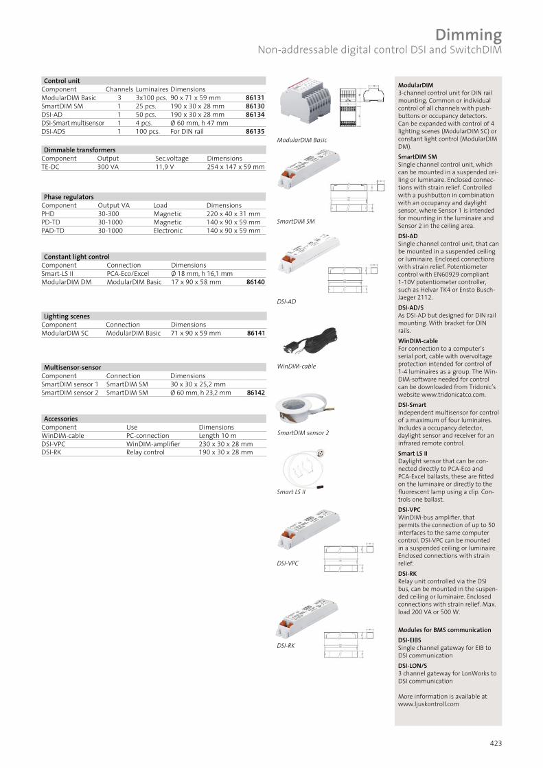
ModularDIM3-channel control unit for DIN rail mounting. Common or individual control of all channels with push-buttons or occupancy detectors. Can be expanded with control of 4 lighting scenes (ModularDIM SC) or constant light control (ModularDIM DM).SmartDIM SMSingle channel control unit, which can be mounted in a suspended cei-ling or luminaire. Enclosed connec-tions with strain relief. Controlled with a pushbutton in combination with an occupancy and daylight sensor, where Sensor 1 is intended for mounting in the luminaire and Sensor 2 in the ceiling area. DSI-AD Single channel control unit, that can be mounted in a suspended ceiling or luminaire. Enclosed connections with strain relief. Potentiometer control with EN60929 compliant 1-10V potentiometer controller, such as Helvar TK4 or Ensto Busch-Jaeger 2112.DSI-AD/SAs DSI-AD but designed for DIN rail mounting. With bracket for DIN rails.WinDIM-cableFor connection to a computer’s serial port, cable with overvoltage protection intended for control of 1-4 luminaires as a group. The Win-DIM-software needed for control can be downloaded from Tridonic’s website www.tridonicatco.com.DSI-SmartIndependent multisensor for control of a maximum of four luminaires. Includes a occupancy detector, daylight sensor and receiver for an infrared remote control.Smart LS IIDaylight sensor that can be con-nected directly to PCA-Eco and PCA-Excel ballasts, these are fitted on the luminaire or directly to the fluorescent lamp using a clip. Con-trols one ballast. DSI-VPCWinDIM-bus amplifier, that permits the connection of up to 50 interfaces to the same computer control. DSI-VPC can be mounted in a suspended ceiling or luminaire. Enclosed connections with strain relief. DSI-RKRelay unit controlled via the DSI bus, can be mounted in the suspen-ded ceiling or luminaire. Enclosed connections with strain relief. Max. load 200 VA or 500 W.
Modules for BMS communication DSI-EIBS Single channel gateway for EIB to DSI communication DSI-LON/S3 channel gateway for LonWorks to DSI communication
More information is available at www.ljuskontroll.com
SmartDIM sensor 2
Dimmable transformersComponent Output Sec.voltage DimensionsTE-DC 300 VA 11,9 V 254 x 147 x 59 mm
Phase regulatorsComponent Output VA Load DimensionsPHD 30-300 Magnetic 220 x 40 x 31 mmPD-TD 30-1000 Magnetic 140 x 90 x 59 mmPAD-TD 30-1000 Electronic 140 x 90 x 59 mm
AccessoriesComponent Use DimensionsWinDIM-cable PC-connection Length 10 mDSI-VPC WinDIM-amplifier 230 x 30 x 28 mmDSI-RK Relay control 190 x 30 x 28 mm
Control unitComponent Channels Luminaires DimensionsModularDIM Basic 3 3x100 pcs. 90 x 71 x 59 mm 86131SmartDIM SM 1 25 pcs. 190 x 30 x 28 mm 86130DSI-AD 1 50 pcs. 190 x 30 x 28 mm 86134DSI-Smart multisensor 1 4 pcs. Ø 60 mm, h 47 mmDSI-ADS 1 100 pcs. For DIN rail 86135
Constant light controlComponent Connection DimensionsSmart-LS II PCA-Eco/Excel Ø 18 mm, h 16,1 mmModularDIM DM ModularDIM Basic 17 x 90 x 58 mm 86140
Lighting scenesComponent Connection DimensionsModularDIM SC ModularDIM Basic 71 x 90 x 59 mm 86141
Multisensor-sensorComponent Connection DimensionsSmartDIM sensor 1 SmartDIM SM 30 x 30 x 25,2 mmSmartDIM sensor 2 SmartDIM SM Ø 60 mm, h 23,2 mm 86142
Dimming Non-addressable digital control DSI and SwitchDIM

HF-ballast
HF-ballast
Luminaire 1
Luminaire 2 etc
424
The majority of dimmable HF-bal-lasts are designed in accordance with the standard EN60929 in-cluding the control of HF-ballasts with 1-10V direct voltage. The HF-ballast creates the requisite control current itself and in the simplest form a potentiometer (usually linear, about 47 k) is enough for control. Most manu-facturers’ potentiometer controls also include electronics.
The HF-ballast senses the voltage in the control circuit. The lower the voltage, the lower the lighting level. If the control circuit is left open, the luminaire lights at full strength in the same way as an non-con-trolled luminaire operates. If the circuit is closed the lighting level drops to the minimum value. The minimum level of luminous flux varies depending on the manufacturer, type and light source. Normal minimum levels for linear fluorescent lamps are 1-5%, and 3-10% for compact fluorescent lamps. Check which levels apply for the lumin-aire you are interested in. Apart from the phase, neutral and protective conductors, two other control circuit wires are connected to the luminaire. The control wires can be placed in the same conduit as the mains voltage cable feeding the luminaire. Even if the control voltage is a maximum of 10V the insulation on the control wires must conform to the demands for a heavy current installation. You must ensure the polarity is correct when connecting the control circuit as incorrect connection can mean the installation drops to its minimum state. In addition to the control wires, the phase conductor should also be connected via the control unit or combined potentiometer/mains switch, as the luminaires can only be switched on and off via the mains voltage. It is important to remember this when planning the cabling, as changes to the installation may be difficult at a later stage. The breaking capacity of the potentiometer’s switch should be taken into consideration during installation. Even if the potentiome-ter is capable of regulating up to 50 HF-ballasts, the capacity of the switch is usually 5-10 luminaires depending on their load. Contactors are needed for greater loads.
Dimming 1-10V
Note• When selecting the control system you should take the system’s and
luminaire’s compatibility into consideration. Luminaires designed ac-cording to the standard EN 60929 feed the control circuits themsel-ves, which not all analogue control units permit.
• There are special demands for running control cables in enclosures together with other high current cables.
• The polarity of the control circuit must be maintained throughout. Regulation does not work correctly if the polarity is crossed on any of the luminaires in a group.
Analogue 1-10V direct voltage control (EN60929)
Ensto Busch-Jaeger 2112 As above, but with surface moun-ted installation box.
Subject to alteration.
Control units
Component Luminaire Switching capacity Ensto Busch-Jaeger 2112 recessed 50 4 A 86080Ensto Busch-Jaeger 2112 surface mounted 50 4 A 86081
Ensto Busch-Jaeger 2112 Rotary potentiometer for reces-sed installation. Suitable for light control of a 1-10V system. Integrated switch with breaking capacity 4 A (cosf > 0.9). Avoid igniting/extinguishing more than 4 luminaires. Additional contac-tors are needed when greater loads are ignited/extinguished. A maximum of 50 HF-ballasts can be controlled.

425
SensorsTridonic SmartDIM SM
The Tridonic SmartDIM SM-concept is a sensor system for oc-cupancy detection and constant light. All control takes place by means of DSI-signals, therefore luminaires equipped with Tridonics’s HF-ballasts types PCA ECO or PCA EXCEL are required. A maximum of 25 HF-ballasts can be connected to a system. Can also be combined with phase control dimming, i.e. SwitchDIM. This type of control is connected to the SmartDIM SM control unit located in the luminaire. Other luminaires connected in the system are controlled via DSI-signals (2-wire) from the control unit.
Two different sensor designs are available: SmartDIM Sensor 1, which is the smallest of the units and is desig-ned for mounting in luminaires and SmartDIM Sensor 2, which is slightly larger and is ideal for recess mounting in the ceiling.There is also a mirror, Smart DIM Mirror, available as an accessory for SmartDIM Sensor 1. This mirror extends the detection zone in one direction. Suited to corridor applications for example.Smart DIM Mirror can also act as a shield.
The following functions can be set on the control unit by using its DIP-switches:
• minimum light level required (1 or 10%).• how the constant light level can be altered. (functionality of the
connected push button).• delay time when no occupancy has been detected. Either a fixed
time of 20 minutes (last 2 minutes at min. light) or an adaptive setting, where the sensors memorises and stores a suitable time level based on the amount of movement in the detection zone.
You can also select whether you want the sensor to ignite and extinguish the luminaire (Auto) or whether you want automatic extinguishing but manual ignition (Man) via the sensor.
More information can be found at www.ljuskontroll.com
SmartDIM Sensor 2, for recess mounting in the ceiling.
Setting options using the DIP-switches on the control unit.
SmartDIM Sensor 1 with the accessory Smart DIM Mirror, which is used to shield or extend the detection zone.
Classroom exposed to daylight where each row of luminaires is individually controlled by a sensor mounted within one of the luminaires in the row. Allows good constant light control giving a balanced lighting level over the entire area, irrespective of the amount of incident daylight. The entire system is controlled via SwitchDIM. The white board lighting is controlled separately.

426
SensorsTridonic SmartSWITCH
Tridonic SmartSWITCH is a basic on/off sensor that “controls” the connected luminaire via the mains voltage. The sensor can control a load of max 200VA/500W. Sensor is designed to be integrated in the luminaire.
A mirror, Smart DIM Mirror, is available as an accessory to Smart-SWITCH. This mirror extends the detection zone in one direction, for use in corridors for example. SmartDIM Mirror can also act as a shield.
The following functions can be set: • extinguishing delay 5 seconds to 30 minutes• extinguishing at a light level between 50-2000 lx. This function
can also be disconnected.
More information can be found at www.ljuskontroll.comSmartDIM Sensor 1 with the accessory SmartDIM Mirror. The accessory is used to screen off or expand the detection zone.
SensorsPhilips OccuSwitch
Philips OccuSwitch is a sensor that controls on/off switching via the mains voltage. It supports loads up to 10 A and is intended for installation in the ceiling. Due to its size it can not normally be installed in a luminaire.
The following functions can be set: • extinguishing delay 1 to 35 minutes• extinguishing at a light level between 10-1000 lx. This function
can also be disconnected.
More information can be found at www.lighting.philips.com
Due to its size PHILIPS OccuSwitch is not suitable for integration in the luminaire.
SensorsPhilips LuxSense
Philips LuxSense is a constant light sensor. The sensor is con-nected directly to the analogue (1-10 V) dimming HF-ballast. A maximum of 20 Philips HF-ballasts type HF-R for 1-10 V can be connected to the same sensor.
The sensor is fitted to a clip, which is snapped directly onto the fluorescent lamp. LuxSense is available in two different designs, for T5 (LRL1220T5) and T8 (LRL1220T8). The required light level can be set by twisting the lower part of the sensor (see picture).
More information can be found at www.lighting.philips.com
A smartSWITCH controlling several slave luminaires in a corridor.

427
SensorsLumisense II
Lumisense II from Philips is based on the DALI protocol, thus luminaires must be equipped with a DALI HF-ballasts. The system is structured in such a way that programming is not necessary for most areas of application. The sensor features occupancy detection, constant light as well as IR. functionality for remote control. All three sensors are collec-ted in a single unit and can for example be built into the louvre. The sensor is intended for use in offices or conference rooms. Up to seven slave luminaires can be connected to the luminaire in which the sensor is integrated. It is also possible to group the luminaires, via a remote control, for different functionality.
Smaller systems, where all luminaires are to perform in the same way, generally do not require any programming. However, modifications can be made using the special remote control for programming, IRT8099. A number of preset positions (or modes) can be selected. A mode can best be described as the type of environment where the product is to be used. For example, an installation in a cellular office is different to an installation in a corridor. Select the most appropriate mode on the remote control, aim it at the sensor and press the green button (send). The luminaire setting is then updated as required.
More information can be found at www.lighting.philips.com
Schematic of the Lumisense II with the three sensors for IR, occupancy detection and constant light.
Sensor connected to control four luminaires (max seven slave luminaires can be connected).
Sensor connected to control only one slave luminaire.
Using the remote control for programming, IRT8099, it is easy to set the required function. Select the function, aim the remote control at the sensor, and send the required setting to the luminaires via the green “send” button. The constant light level can also be adjusted if the preset level of 500-600 lx is unsuitable.