4g/lte/nb-iot module with uno to pcie board user manual · 4g/lte/nb-iot module with uno to pcie...
TRANSCRIPT

4G/LTE/NB-IoT Module with UNO to PCIe board
Aug 26, 2019 Page 1 of 24 Rev 1.01
4G
/LT
E/N
B-Io
T M
odule
with
UN
O to
PC
Ie b
oard
US
ER
MA
NU
AL
Maker N
u-m
bed
NU
C472 U
ser M
an
ual
ARM® Cortex® -M
32-bit Microcontroller
4G/LTE/NB-IoT Module
with UNO to PCIe board
User Manual
The information described in this document is the exclusive intellectual property of Nuvoton Technology Corporation and shall not be reproduced without permission from Nuvoton.
Nuvoton is providing this document only for reference purposes of NuMicro microcontroller based system design. Nuvoton assumes no responsibility for errors or omissions.
All data and specifications are subject to change without notice.
For additional information or questions, please contact: Nuvoton Technology Corporation.
www.nuvoton.com

4G/LTE/NB-IoT Module with UNO to PCIe board
Aug 26, 2019 Page 2 of 24 Rev 1.01
4G
/LT
E/N
B-Io
T M
odule
with
UN
O to
PC
Ie b
oard
US
ER
MA
NU
AL
Maker N
u-m
bed
NU
C472 U
ser M
an
ual
Table of Contents
1 Overview ............................................................................................. 5
Brief Introduction to NuMaker-IoT-M487 Board ................................................... 7
Brief Introduction to NuMaker NUC980 IIoT Board (NK-980IOT) .............................. 7
Brief Introduction to NuMaker-IoT-M263A Board (NK-IOT-M263A) ........................... 8
2 4G/LTE/NB-IoT Module with UNO to PCIe board ........................................... 10
Quectel EC21 and BG96 module board with UNO to PCIe board ............................ 10
3 UNO to PCIe Board Overview ................................................................. 12
Front View .............................................................................................. 12
Rear View .............................................................................................. 13
Pin Assignment for mini PCIe interface ........................................................... 15
Arduino UNO Compatible Interface ................................................................ 16
PCB Placement ....................................................................................... 18
4 UNO to PCIe board Schematics ............................................................... 19
Interface Connectors ................................................................................. 19
mini PCIe interface ................................................................................... 20
SIM Card ............................................................................................... 21
USB Device ............................................................................................ 22
5 REVISION HISTORY ............................................................................ 23

4G/LTE/NB-IoT Module with UNO to PCIe board
Aug 26, 2019 Page 3 of 24 Rev 1.01
4G
/LT
E/N
B-Io
T M
odule
with
UN
O to
PC
Ie b
oard
US
ER
MA
NU
AL
Maker N
u-m
bed
NU
C472 U
ser M
an
ual
List of Figures
Figure 1-1 Combination of UNO to PCIe Board and NuMaker-IoT-M487 Board ............................. 5
Figure 1-2 Combination of UNO to PCIe Board and NuMaker NUC980 IIoT Board ....................... 5
Figure 1-3 Combination of UNO to PCIe Board and NuMaker-IoT-M263A Board .......................... 6
Figure 1-4 NuMaker-IoT-M487 Board .............................................................................................. 7
Figure 1-5 NuMaker NUC980 IIoT Board (NK-980IOT) ................................................................... 8
Figure 1-6 NuMaker-IoT-M263A Board (NK-IOT-M263A) ............................................................... 9
Figure 2-1 Front view of Quectel EC21 module board on UNO to PCIe board ............................. 10
Figure 2-2 Front view of Quectel BG96 module board on UNO to PCIe board ............................. 10
Figure 2-3 The switch setting view of Quectel EC21 and BG96 module board with UNO to PCIe board ....................................................................................................................................... 11
Figure 3-1 Front View of UNO to PCIe Board ................................................................................ 12
Figure 3-2 Rear View of UNO to PCIe Board ................................................................................ 14
Figure 3-3 Arduino UNO Compatible Interface .............................................................................. 16
Figure 3-4 Front Placement ........................................................................................................... 18
Figure 3-5 Rear Placement ............................................................................................................ 18
Figure 4-1 Interface Connectors .................................................................................................... 19
Figure 4-2 mini PCIe interface ....................................................................................................... 20
Figure 4-3 SIM Card Circuit ........................................................................................................... 21
Figure 4-4 USB Device Circuit ....................................................................................................... 22

4G/LTE/NB-IoT Module with UNO to PCIe board
Aug 26, 2019 Page 4 of 24 Rev 1.01
4G
/LT
E/N
B-Io
T M
odule
with
UN
O to
PC
Ie b
oard
US
ER
MA
NU
AL
Maker N
u-m
bed
NU
C472 U
ser M
an
ual
List of Tables
Table 2-1 The switch setting for Quectel EC21 and BG96 module board. .................................... 11
Table 3-1 Pin Assignment for mini PCIe interface ......................................................................... 15
Table 3-2 Arduino UNO Interface of NuMaker-IoT-M487 board and NK-980IoT board Mapping with UNO to PCIe Board ......................................................................................................... 17
4G/LTE/NB-IoT Module with UNO to PCIe board
Aug 26, 2019 Page 5 of 24 Rev 1.01
4G
/LT
E/N
B-Io
T M
odule
with
UN
O to
PC
Ie b
oard
US
ER
MA
NU
AL
Maker N
u-m
bed
NU
C472 U
ser M
an
ual
1 OVERVIEW
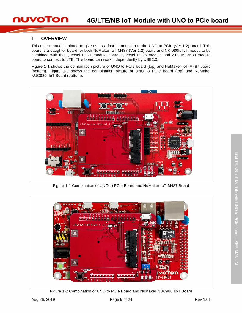
This user manual is aimed to give users a fast introduction to the UNO to PCIe (Ver 1.2) board. This board is a daughter board for both NuMaker-IoT-M487 (Ver 1.2) board and NK-980IoT. It needs to be combined with the Quectel EC21 module board, Quectel BG96 module and ZTE ME3630 module board to connect to LTE. This board can work independently by USB2.0.
Figure 1-1 shows the combination picture of UNO to PCIe board (top) and NuMaker-IoT-M487 board (bottom). Figure 1-2 shows the combination picture of UNO to PCIe board (top) and NuMaker NUC980 IIoT Board (bottom).
Figure 1-1 Combination of UNO to PCIe Board and NuMaker-IoT-M487 Board
Figure 1-2 Combination of UNO to PCIe Board and NuMaker NUC980 IIoT Board

4G/LTE/NB-IoT Module with UNO to PCIe board
Aug 26, 2019 Page 6 of 24 Rev 1.01
4G
/LT
E/N
B-Io
T M
odule
with
UN
O to
PC
Ie b
oard
US
ER
MA
NU
AL
Maker N
u-m
bed
NU
C472 U
ser M
an
ual
The UNO to PCIe (Ver 1.2) board is not necessary for NuMaker-IoT-M263A board (NK-IOT-M263A), just plug Quectel EC21 or BG96 module board into PCIe connector of NuMaker-IoT-M263A board directly. Please refer to user manual of NuMaker-IoT-M263A board. Figure 1-3 shows the combination picture of Quectel EC21/BG96 module board and NuMaker-IoT-M263A board.
Figure 1-3 Combination of UNO to PCIe Board and NuMaker-IoT-M263A Board
4G/LTE/NB-IoT Module with UNO to PCIe board
Aug 26, 2019 Page 7 of 24 Rev 1.01
4G
/LT
E/N
B-Io
T M
odule
with
UN
O to
PC
Ie b
oard
US
ER
MA
NU
AL
Maker N
u-m
bed
NU
C472 U
ser M
an
ual
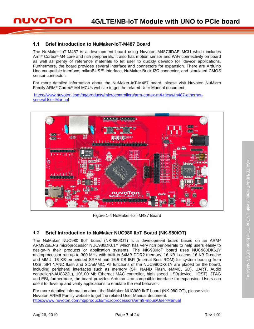
Brief Introduction to NuMaker-IoT-M487 Board
The NuMaker-IoT-M487 is a development board using Nuvoton M487JIDAE MCU which includes Arm® Cortex® -M4 core and rich peripherals. It also has motion sensor and WiFi connectivity on board as well as plenty of reference materials to let user to quickly develop IoT device applications. Furthermore, the board provides several interface and connectors for expansion. There are Arduino Uno compatible interface, mikroBUS™ interface, NuMaker Brick I2C connector, and simulated CMOS sensor connector.
For more detailed information about the NuMaker-IoT-M487 board, please visit Nuvoton NuMicro Family ARM® Cortex® -M4 MCUs website to get the related User Manual document.
https://www.nuvoton.com/hq/products/microcontrollers/arm-cortex-m4-mcus/m487-ethernet-series/User-Manual
Figure 1-4 NuMaker-IoT-M487 Board
Brief Introduction to NuMaker NUC980 IIoT Board (NK-980IOT)
The NuMaker NUC980 IIoT board (NK-980IOT) is a development board based on an ARM® ARM926EJ-S microprocessor NUC980DK61Y which has very rich peripherals to help users easily to design-in their products or application systems. The NK-980IoT board uses NUC980DK61Y microprocessor run up to 300 MHz with built-in 64MB DDR2 memory, 16 KB I-cache, 16 KB D-cache and MMU, 16 KB embedded SRAM and 16.5 KB IBR (Internal Boot ROM) for system booting from USB, SPI NAND flash and SD/eMMC, All functions of the NUC980DK61Y are placed on the board, including peripheral interfaces such as memory (SPI NAND Flash, eMMC, SD), UART, Audio controller(NAU8822L), 10/100 Mb Ethernet MAC controller, high speed USB(device, HOST), JTAG and EBI, furthermore, the board provides Arduino Uno compatible interface for expansion. Users can use it to develop and verify applications to emulate the real behavior.
For more detailed information about the NuMaker NUC980 IIoT board (NK-980IOT), please visit Nuvoton ARM9 Family website to get the related User Manual document. https://www.nuvoton.com/hq/products/microprocessors/arm9-mpus/User-Manual
4G/LTE/NB-IoT Module with UNO to PCIe board
Aug 26, 2019 Page 8 of 24 Rev 1.01
4G
/LT
E/N
B-Io
T M
odule
with
UN
O to
PC
Ie b
oard
US
ER
MA
NU
AL
Maker N
u-m
bed
NU
C472 U
ser M
an
ual
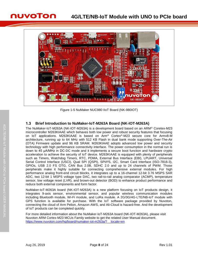
Figure 1-5 NuMaker NUC980 IIoT Board (NK-980IOT)
Brief Introduction to NuMaker-IoT-M263A Board (NK-IOT-M263A)
The NuMaker-IoT-M263A (NK-IOT-M263A) is a development board based on an ARM® Coretex-M23 microcontroller M263KIAAE which behaves both low power and robust security features that focusing on IoT applications. M263KIAAE is based on Arm® Cortex® -M23 secure core for Armv8-M architecture, running up to 64 MHz with 512 KB Flash in dual bank mode supporting Over-The-Air (OTA) Firmware update and 96 KB SRAM. M263KIAAE adopts advanced low power and security technology with high performance connectivity interface. The power consumption in the normal run is down to 45 μA/MHz in DC-DC mode and it implements a secure boot function and hardware crypto acceleration to achieve the security of IoT device. M263KIAAE is equipped with plenty of peripherals such as Timers, Watchdog Timers, RTC, PDMA, External Bus Interface (EBI), LPUART, Universal Serial Control Interface (USCI), Qual SPI (QSPI), SPI/I²S, I2C, Smart Card Interface (ISO-7816-3), GPIOs, USB 2.0 FS OTG, CAN Bus 2.0B, SDHC 2.0 and up to 24 channels of PWM. Those peripherals make it highly suitable for connecting comprehensive external modules. For high performance analog front-end circuit blocks, it integrates up to a 16-channel 12-bit 3.76 MSPS SAR ADC, two 12-bit 1 MSPS voltage type DAC, two rail-to-rail analog comparator (ACMP), temperature sensor, low voltage reset (LVR), and brown-out detector (BOD) to enhance product performance and reduce both external components and form factor.
NuMaker-IoT-M263A board (NK-IOT-M263A) is a new platform focusing on IoT products design, it integrates 9-axis sensor, environmental sensor, and popular wireless communication modules including Bluetooth module, Wi-Fi module, and LoRa module. A 2G/3G/4G-LTE/NB-IoT module with GPS function is available for purchase. With the IoT software package provided by Nuvoton, connecting the cloud of Arm Pelion, Amazon AWS, and Ali-Cloud is hazard-free. And the development of IoT products can be completed quickly.
For more detailed information about the NuMaker-IoT-M263A board (NK-IOT-M263A), please visit Nuvoton ARM Cortex-M23 MCUs Family website to get the related User Manual document. https://www.nuvoton.com/hq/board/numaker-iot-m263a/?__locale=en

4G/LTE/NB-IoT Module with UNO to PCIe board
Aug 26, 2019 Page 9 of 24 Rev 1.01
4G
/LT
E/N
B-Io
T M
odule
with
UN
O to
PC
Ie b
oard
US
ER
MA
NU
AL
Maker N
u-m
bed
NU
C472 U
ser M
an
ual
Figure 1-6 NuMaker-IoT-M263A Board (NK-IOT-M263A)

4G/LTE/NB-IoT Module with UNO to PCIe board
Aug 26, 2019 Page 10 of 24 Rev 1.01
4G
/LT
E/N
B-Io
T M
odule
with
UN
O to
PC
Ie b
oard
US
ER
MA
NU
AL
Maker N
u-m
bed
NU
C472 U
ser M
an
ual
2 4G/LTE/NB-IOT MODULE WITH UNO TO PCIE BOARD
Quectel EC21 and BG96 module board with UNO to PCIe board
This UNO to PCIe board supports Quectel EC21 module board and Quectel BG96 module board. For more detailed information about Quectel EC21 and BG96 module board, please visit Quectel website to get the related User Manual document.
Quectel EC21: https://www.quectel.com/product/ec21.htm Quectel BG96: https://www.quectel.com/product/BG96.htm
Figure 2-1 shows the front side of Quectel EC21 module board on UNO to PCIe board. Figure 2-2 shows the front side of Quectel BG96 module board on UNO to PCIe board. Figure 2-3 shows the switch setting of Quectel EC21 and BG96 module board with UNO to PCIe board. Table 2-1 shows the switch setting for Quectel EC21 and BG96 module board.
Figure 2-1 Front view of Quectel EC21 module board on UNO to PCIe board
Figure 2-2 Front view of Quectel BG96 module board on UNO to PCIe board

4G/LTE/NB-IoT Module with UNO to PCIe board
Aug 26, 2019 Page 11 of 24 Rev 1.01
4G
/LT
E/N
B-Io
T M
odule
with
UN
O to
PC
Ie b
oard
US
ER
MA
NU
AL
Maker N
u-m
bed
NU
C472 U
ser M
an
ual
Figure 2-3 The switch setting view of Quectel EC21 and BG96 module board with UNO to PCIe board
Table 2-1 The switch setting for Quectel EC21 and BG96 module board.
SW Status Function GPIO pin of UNO
interface
SW2.1 OFF UART_CTS D12
SW2.2 OFF UART_RTS D11
SW2.3 OFF UART_TXD D10
SW2.4 OFF UART_RXD D13
SW3.1 OFF UART_CTS D9
SW3.2 OFF UART_RTS D8
SW3.3 ON UART_TXD D1
SW3.4 ON UART_RXD D0
SW4.1 ON UART power supply 3.3V
SW4.2 OFF UART power supply 3.3V
SW4.3 X None None
SW4.4 X None None
4G/LTE/NB-IoT Module with UNO to PCIe board
Aug 26, 2019 Page 12 of 24 Rev 1.01
4G
/LT
E/N
B-Io
T M
odule
with
UN
O to
PC
Ie b
oard
US
ER
MA
NU
AL
Maker N
u-m
bed
NU
C472 U
ser M
an
ual
3 UNO TO PCIE BOARD OVERVIEW
Front View
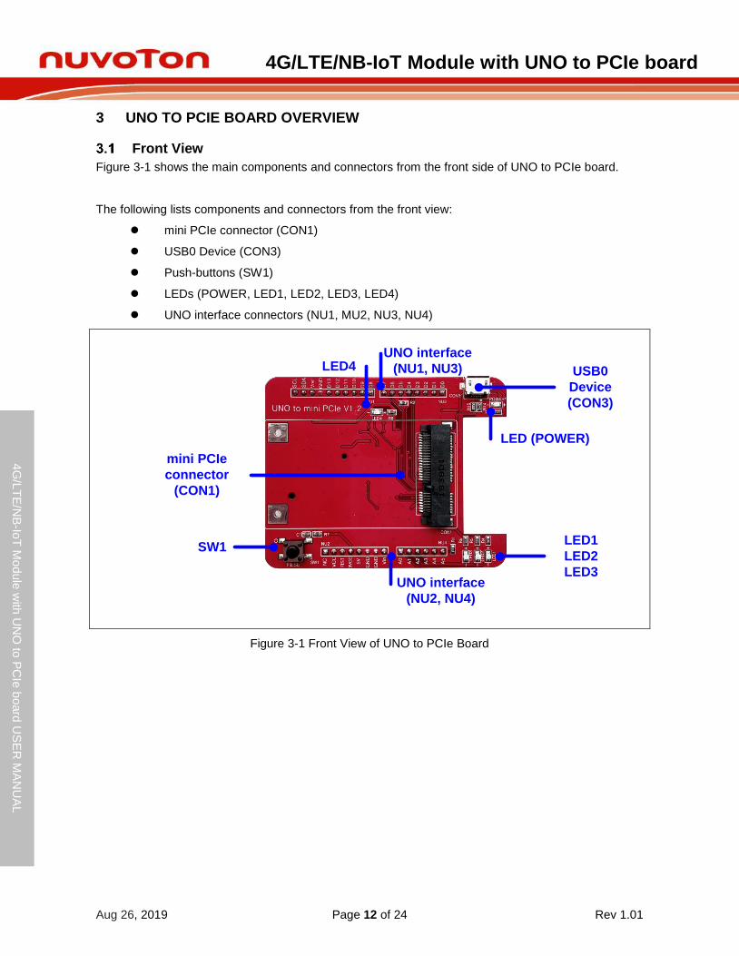
Figure 3-1 shows the main components and connectors from the front side of UNO to PCIe board.
The following lists components and connectors from the front view:
mini PCIe connector (CON1)
USB0 Device (CON3)
Push-buttons (SW1)
LEDs (POWER, LED1, LED2, LED3, LED4)
UNO interface connectors (NU1, MU2, NU3, NU4)
LED (POWER)
mini PCIe
connector
(CON1)
SW1LED1
LED2
LED3
UNO interface
(NU1, NU3) USB0
Device
(CON3)
UNO interface
(NU2, NU4)
LED4
Figure 3-1 Front View of UNO to PCIe Board

4G/LTE/NB-IoT Module with UNO to PCIe board
Aug 26, 2019 Page 13 of 24 Rev 1.01
4G
/LT
E/N
B-Io
T M
odule
with
UN
O to
PC
Ie b
oard
US
ER
MA
NU
AL
Maker N
u-m
bed
NU
C472 U
ser M
an
ual
Rear View
Figure 3-2 shows the main components and connectors from the rear side of UNO to PCIe board.
The following lists connectors from the rear view:
Mini SIM card slot for SIM1 (CON2)
Switch for UART pins of NuMaker-IoT-M487 board (SW2)
SW Status Function GPIO pin of UNO
interface
SW2.1 ON UART_CTS D12
SW2.2 ON UART_RTS D11
SW2.3 ON UART_TXD D10
SW2.4 ON UART_RXD D13
Switch for UART pins of NuMaker NUC980 IIoT board (SW3)
SW Status Function GPIO pin of UNO
interface
SW3.1 ON UART_CTS D9
SW3.2 ON UART_RTS D8
SW3.3 ON UART_TXD D1
SW3.4 ON UART_RXD D0
Note: Only one switch of SW2 and SW3 can be used and cannot be used at the same time. If users only need to use UART_TXD and UART_RXD, users can turn on SW3.3 and SW3.4 regardless of NuMaker-IoT-M487 board and NuMaker NUC980 IIoT Board board.
Switch for UART power supply (SW4)
SW Status Function power
SW4.1/ SW4.2 ON/OFF UART power supply 3.3V
SW4.1/ SW4.2 OFF/ON UART power supply 1.8V

4G/LTE/NB-IoT Module with UNO to PCIe board
Aug 26, 2019 Page 14 of 24 Rev 1.01
4G
/LT
E/N
B-Io
T M
odule
with
UN
O to
PC
Ie b
oard
US
ER
MA
NU
AL
Maker N
u-m
bed
NU
C472 U
ser M
an
ual
SIM Card slot
(CON2)
SW2
SW4
SW3
Figure 3-2 Rear View of UNO to PCIe Board

4G/LTE/NB-IoT Module with UNO to PCIe board
Aug 26, 2019 Page 15 of 24 Rev 1.01
4G
/LT
E/N
B-Io
T M
odule
with
UN
O to
PC
Ie b
oard
US
ER
MA
NU
AL
Maker N
u-m
bed
NU
C472 U
ser M
an
ual
Pin Assignment for mini PCIe interface
The UNO to PCIe daughter board is equipped with mini PCIe connecter, USB2.0, Sim Card and one push button for user developing and verifying some special feature. Besides, the pin arrangement of UNO to PCIe is compatible with Arduino UNO.
This UNO to PCIe board supports Quectel EC21 module board, Quectel BG96 module board and ZTE ME3630 module board. Table 3-1 shows the pin assignment for mini PCIe interface.
Table 3-1 Pin Assignment for mini PCIe interface
Pin No. PCIe Pin Name Pin No. PCIe Pin Name
1 WAKE# 2 3VCC
3 - 4 GND
5 - 6 -
7 - 8 SC_PWR
9 GND 10 SC_DAT
11 UART_RXD 12 SC_CLK
13 UART_TXD 14 SC_RST
15 GND 16 -
17 UART_RI 18 GND
19 - 20 W_DISABLE
21 GND 22 PERST#
23 UART_CTS 24 -
25 UART_RTS 26 GND
27 GND 28 -
29 GND 30 -
31 UART_DTR 32 -
33 UART_DCD 34 GND
35 GND 36 PCIe_USB_DM
37 GND 38 PCIe_USB_DP
39 3VCC 40 GND
41 3VCC 42 LED_WWAN#
43 GND 44 -
45 - 46 -
47 - 48 -
49 - 50 GND
51 - 52 3VCC

4G/LTE/NB-IoT Module with UNO to PCIe board
Aug 26, 2019 Page 16 of 24 Rev 1.01
4G
/LT
E/N
B-Io
T M
odule
with
UN
O to
PC
Ie b
oard
US
ER
MA
NU
AL
Maker N
u-m
bed
NU
C472 U
ser M
an
ual
Arduino UNO Compatible Interface
Figure 3-3 shows the Arduino UNO compatible interface.
The Table 3-2 shows the mapping tables on these connector headers of NuMaker-IoT-M487 board and NK-980IoT board.
Figure 3-3 Arduino UNO Compatible Interface

4G/LTE/NB-IoT Module with UNO to PCIe board
Aug 26, 2019 Page 17 of 24 Rev 1.01
4G
/LT
E/N
B-Io
T M
odule
with
UN
O to
PC
Ie b
oard
US
ER
MA
NU
AL
Maker N
u-m
bed
NU
C472 U
ser M
an
ual
Table 3-2 Arduino UNO Interface of NuMaker-IoT-M487 board and NK-980IoT board Mapping with UNO to PCIe Board
Header
UNO to PCIe Board
Header
UNO to PCIe Board
Compatible to Arduino UNO
UNO to PCIe Board Compatible to Arduino UNO
UNO to PCIe Board
N U 2
NU2.1 NC
- N U 1
NU1.10 I2C_SCL
-
NU2.2 VDD NU1.9 I2C_SDA
NU2.3 MCU_RESET NU1.8 VREF
NU2.4 3VCC NU1.7 GND
NU2.5 5VCC NU1.6 D13 UART_RXD_480
NU2.6 GND NU1.5 D12 UART_CTS_480
NU2.7 GND NU1.4 D11 UART_RTS_480
NU2.8 VIN NU1.3 D10 UART_TXD_480
N U 4
NU4.1 A0 LED1 NU1.2 D9 UART_CTS_980
NU4.2 A1 LED2 NU1.1 D8 UART_RTS_980
NU4.3 A2 LED3
N U 3
NU3.8 D7 WAKE#
NU4.4 A3 - NU3.7 D6 PERST#
NU4.5 A4 - NU3.6 D5 UART_DTR
NU4.6 A5 W_DISABLE NU3.5 D4 UART_RI
NU3.4 D3 UART_DCD
NU5.3 D2 -
NU5.2 D1 UART_TXD_980
NU5.1 D0 UART_RXD_980

4G/LTE/NB-IoT Module with UNO to PCIe board
Aug 26, 2019 Page 18 of 24 Rev 1.01
4G
/LT
E/N
B-Io
T M
odule
with
UN
O to
PC
Ie b
oard
US
ER
MA
NU
AL
Maker N
u-m
bed
NU
C472 U
ser M
an
ual
PCB Placement
Figure 3-4 and Figure 3-5 show the front and rear placement of UNO to PCIe board.
Figure 3-4 Front Placement
Figure 3-5 Rear Placement

4G/LTE/NB-IoT Module with UNO to PCIe board
Aug 26, 2019 Page 19 of 24 Rev 1.01
4G
/LT
E/N
B-Io
T M
odule
with
UN
O to
PC
Ie b
oard
US
ER
MA
NU
AL
Maker N
u-m
bed
NU
C472 U
ser M
an
ual
4 UNO TO PCIE BOARD SCHEMATICS
Interface Connectors
Figure 4-1 shows the all the interface connecters NU1~NU4 that should be connected to the interface connectors NU1~NU4 of NuMaker-IoT-M487 board and NK-980IoT.
Figure 4-1 Interface Connectors
UART 1.8V Level Shifter
3VCC1V8
SW4
2. mm DIP SWITCHES PONIES 4 SMD(HPS604-E)
TVCC
TVCC switch
TVCC
3VCC
CB5
0.1uFC0603
U3ACE1117C18XM+H
IN3
GN
D1
OU
T2
OU
T4
CT110uF/10V
TANT-A
1V8
R1
10K
3.3V to 1.8V
GND
R2
100K
WAKE#
UART_DTRPERST#
UART_RI
UART_RTS_480UART_CTS_480UART_RXD_480GND
UART_RTS_980
UART_TXD_480
GND
3VCC
UART_DCD
SW1
SMD按鍵開關6X6X5H(黑)卷代
SW4-SMD
PERST#
R710KR0603
3VCC
C11uF
C0603
W_DISABLE WAKE#W_DISABLE
WAKE# PERST#PERST#
RESET
NU2
HEADER 2.54 8X1 male
NC1
VDD2
MCU_RESET3
3VCC4
5VCC5
VSS6
VSS7
VIN8
UART_DCDUART_DCD
NU4
HEADER 2.54 6X1 male
A01
A12
A23
A34
A45
A56
NU1
HEADER 2.54 10X1 male
D81D92D103D114D125D136VSS7VREF8I2C_SDA9I2C_SCL10
NU3
HEADER 2.54 8X1 male
D01D12D23D34D45D56D67D78
3VCC
3VCC
N10N7
3VCC
12
LED3
Red(LED0805)
R3
220RR0603
12
POWER1
Red(LED0805)
3VCC
LED
R6
220RR0603
N9
12
LED2
Yellow(LED0805)
3VCC
A1
R5
220RR0603
N8
12
LED1
Green(LED0805)
A0
3VCC
R4
220RR0603
A2
Off-page Connector
GNDGND
3VCC3VCC
UART_RXDUART_TXD
UART_TXDUART_RXD
UART_CTS UART_RTSUART_CTS
UART_RTS
UART_DTRUART_DTR UART_RI
UART_RI
Title
Size Document Number Rev
Date: Sheet of
Interface Connector 1.2
UNO_to_PCIe
nuvoTon Technology Corp.
A3
1 4Tuesday, April 09, 2019
A2A1A0
Interface Connecter
UART_RXD_3VCC
UART_CTS_480SW2
2. mm DIP SWITCHES PONIES 4 SMD(HPS604-E)
UART_RTS_480 UART_CTS_3VCC
UART switch
UART_RXD_480UART_TXD_480
UART_RTS_980UART_CTS_980UART_RTS_3VCC
SW3
2. mm DIP SWITCHES PONIES 4 SMD(HPS604-E)
UART_TXD_3VCC UART_RXD_980UART_TXD_980
UART_CTS_980
UART_RXD_980UART_TXD_980
W_DISABLE
GND
GND
SN74LV2T45DCUR
U1
SSOP-8
GND4 A23
VCCA1
DIR5
A12
B26B17VCCB8
3VCC
3VCC
SN74LV2T45DCUR
U2
SSOP-8
GND4 A23
VCCA1
DIR5
A12
B26B17VCCB8
TVCC
TVCC
UART_RXD_3VCCUART_CTS_3VCC
UART_TXD_3VCCUART_RTS_3VCC
LS_DO_DIR1
UART_CTS
UART_RTS
UART_RXD
UART_TXD
LS_DO_DIR2
CB1
0.1uC0603
CB2
0.1uC0603
3VCC TVCC
CB3
0.1uC0603
3VCC TVCC
CB4
0.1uC0603
4G/LTE/NB-IoT Module with UNO to PCIe board
Aug 26, 2019 Page 20 of 24 Rev 1.01
4G
/LT
E/N
B-Io
T M
odule
with
UN
O to
PC
Ie b
oard
US
ER
MA
NU
AL
Maker N
u-m
bed
NU
C472 U
ser M
an
ual
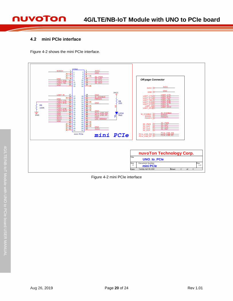
mini PCIe interface
Figure 4-2 shows the mini PCIe interface.
Figure 4-2 mini PCIe interface
W_DISABLEWAKE#
WAKE#W_DISABLE
PERST#PERST#
UART_DCDUART_DCD
UART_DTR UART_RIUART_DTR
UART_RI
UART_DCD
GND
R9
100K
CON1
mini PCIe
11
22
33
44
55
66
77
88
99
1010
1111
1212
1313
1414
1515
1616
1717
1818
1919
2020
2121
2222
2323
2424
2525
2626
2727
2828
2929
3030
3131
3232
3333
3434
3535
3636
3737
3838
3939
4040
4141
4242
4343
4444
4545
4646
4747
4848
4949
5050
5151
5252
Off-page Connector
GND
3VCC
GND
3VCC
UART_RXDUART_TXD
UART_TXDUART_RXD
UART_TXDUART_RXDGND
GND3VCC
GND
SC_DATSC_PWR
PCIe_USB_DM
SC_RSTSC_CLK
GNDPCIe_USB_DP
GND
GND
GND
W_DISABLEPERST#
3VCC
GND
GND
UART_RI
GNDUART_RTSUART_CTS
GND
UART_DTRGND
3VCCGND
GND3VCC
WAKE#
UART_CTS UART_RTSUART_CTS
UART_RTS
LED4Red
3VCC
N3
R8330
LED_WWAN#
mini PCIe
SC_RSTSC_CLK
SC_RSTSC_CLKSC_DAT
SC_DATSC_PWR
Title
Size Document Number Rev
Date: Sheet of
mini PCIe 1.2
UNO_to_PCIe
nuvoTon Technology Corp.
A
2 4Tuesday, April 09, 2019
SC_PWR
PCIe_USB_DM
PCIe_USB_DPPCIe_USB_DM PCIe_USB_DP

4G/LTE/NB-IoT Module with UNO to PCIe board
Aug 26, 2019 Page 21 of 24 Rev 1.01
4G
/LT
E/N
B-Io
T M
odule
with
UN
O to
PC
Ie b
oard
US
ER
MA
NU
AL
Maker N
u-m
bed
NU
C472 U
ser M
an
ual
SIM Card
Figure 4-3 shows the SIM Card circuit.
Figure 4-3 SIM Card Circuit
N5
C633pFC0603
R10
15K
SC
_P
WR
U4SMF15CTSOP-6
22
33
44
66
11
55
SC_PWR
R11 22
R12 22
R13 22N6
N4
C233pFC0603
C333pFC0603
C533pFC0603
SC_DAT
C4100nFC0603
GND
GND
GND
GND
CON2
SIM_Card_1
SIM_VCC1
SIM_RST2
SIM_CLK3
C44
SIM_GND5
SIM_VPP6
SIM_IO7
C88
SIM Card
Off-page Connector
GND
SC_CLK
3VCC3VCC
GND
SC_RSTSC_CLK SC_RST
SC_DATSC_PWR
SC_DATSC_PWR
Title
Size Document Number Rev
Date: Sheet of
SIM Card 1.2
UNO_to_PCIe
nuvoTon Technology Corp.
A
3 4Wednesday, April 03, 2019
SC_RST
SC_CLK
4G/LTE/NB-IoT Module with UNO to PCIe board
Aug 26, 2019 Page 22 of 24 Rev 1.01
4G
/LT
E/N
B-Io
T M
odule
with
UN
O to
PC
Ie b
oard
US
ER
MA
NU
AL
Maker N
u-m
bed
NU
C472 U
ser M
an
ual
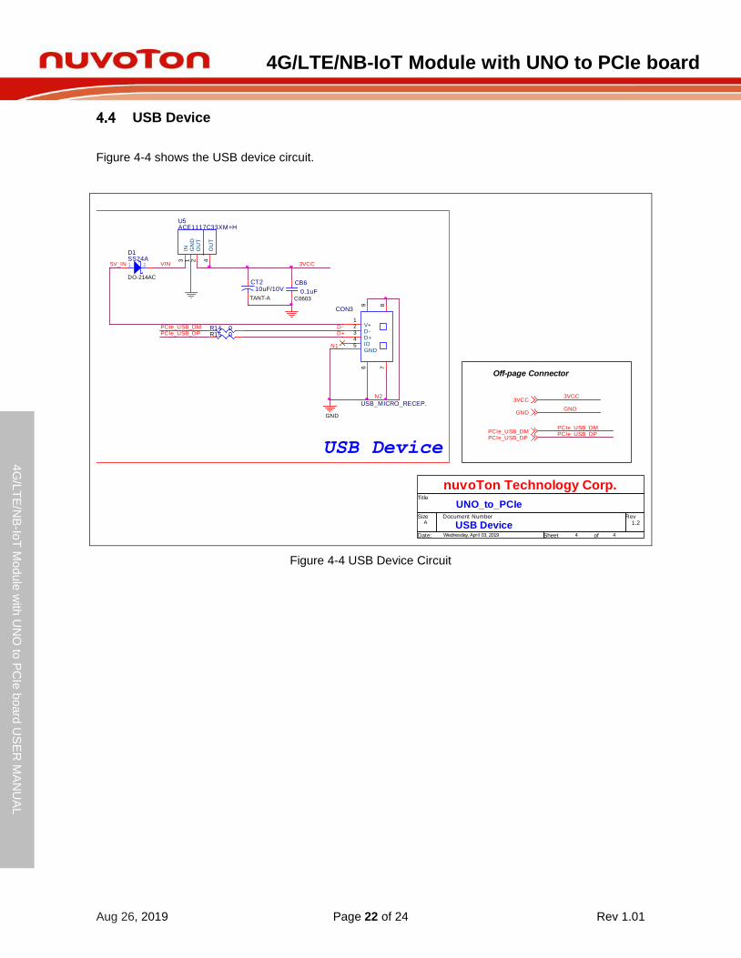
USB Device
Figure 4-4 shows the USB device circuit.
Figure 4-4 USB Device Circuit
VIN
CB6
0.1uFC0603
1 2
D1SS24A
DO-214AC
U5ACE1117C33XM+H
IN3
GN
D1
OU
T2
OU
T4
CT210uF/10V
TANT-A
5V_IN 3VCC
N1
USB Device
GND
Off-page Connector
3VCC
GND
3VCC
PCIe_USB_DPPCIe_USB_DM
PCIe_USB_DPPCIe_USB_DM
GND
N2
PCIe_USB_DPPCIe_USB_DM R14 0
R15 0
CON3
USB_MICRO_RECEP.
V+1
D-2
D+3
ID4
GND5
6 789
D-D+
Title
Size Document Number Rev
Date: Sheet of
USB Device 1.2
UNO_to_PCIe
nuvoTon Technology Corp.
A
4 4Wednesday, April 03, 2019
4G/LTE/NB-IoT Module with UNO to PCIe board
Aug 26, 2019 Page 23 of 24 Rev 1.01
4G
/LT
E/N
B-Io
T M
odule
with
UN
O to
PC
Ie b
oard
US
ER
MA
NU
AL
Maker N
u-m
bed
NU
C472 U
ser M
an
ual
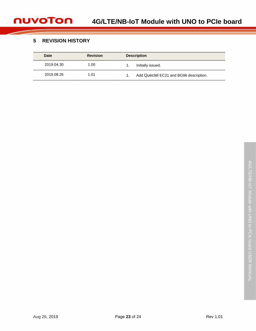
5 REVISION HISTORY
Date Revision Description
2019.04.30 1.00 1. Initially issued.
2019.08.26 1.01 1. Add Quectel EC21 and BG96 description.

4G/LTE/NB-IoT Module with UNO to PCIe board
Aug 26, 2019 Page 24 of 24 Rev 1.01
4G
/LT
E/N
B-Io
T M
odule
with
UN
O to
PC
Ie b
oard
US
ER
MA
NU
AL
Maker N
u-m
bed
NU
C472 U
ser M
an
ual
Important Notice
Nuvoton Products are neither intended nor warranted for usage in systems or equipment, any malfunction or failure of which may cause loss of human life, bodily injury or severe property damage. Such applications are deemed, “Insecure Usage”.
Insecure usage includes, but is not limited to: equipment for surgical implementation, atomic energy control instruments, airplane or spaceship instruments, the control or operation of dynamic, brake or safety systems designed for vehicular use, traffic signal instruments, all types of safety devices, and other applications intended to support or sustain life.
All Insecure Usage shall be made at customer’s risk, and in the event that third parties lay claims to Nuvoton as a result of customer’s Insecure Usage, customer shall indemnify the damages and liabilities thus incurred by Nuvoton.