4k hdmi kvm usb/rs232/ir/analog audio cat5e extender over ... · hkm02bt-4k: 4k hdmi kvm over...
TRANSCRIPT
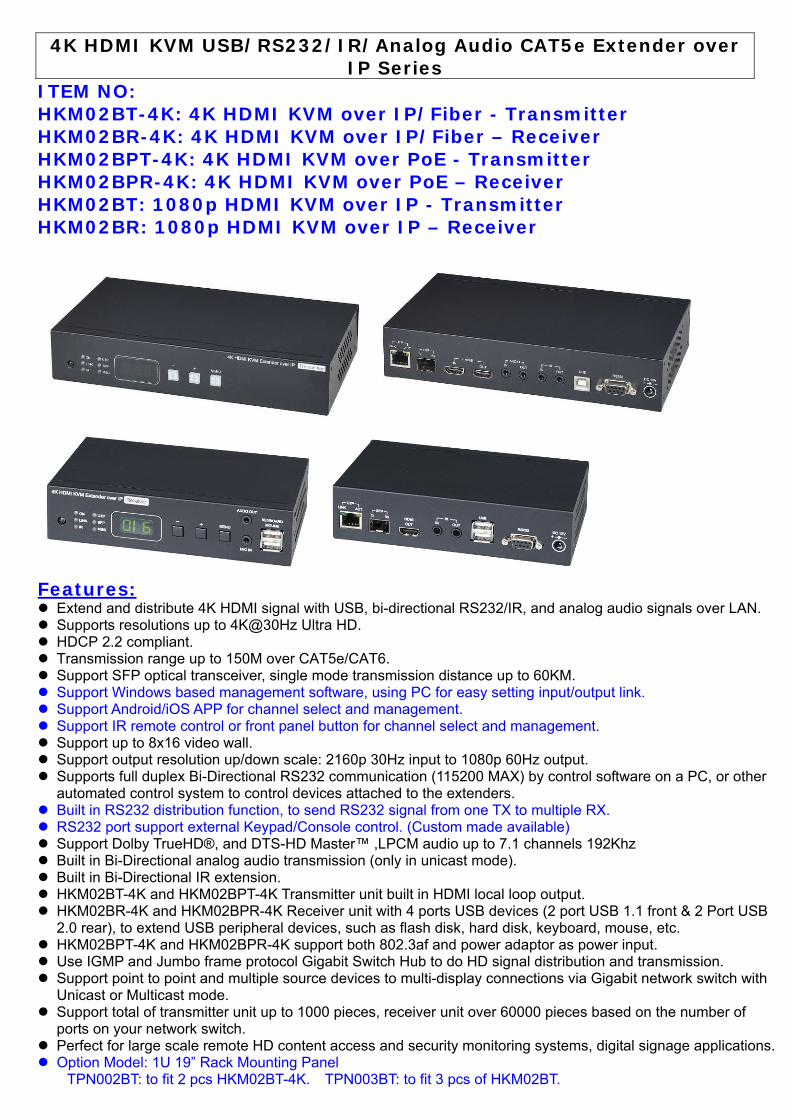
ITEM NO: HKM02BT-4K: 4K HDMI KVM over IP/Fiber - Transmitter HKM02BR-4K: 4K HDMI KVM over IP/Fiber – Receiver HKM02BPT-4K: 4K HDMI KVM over PoE - Transmitter HKM02BPR-4K: 4K HDMI KVM over PoE – Receiver HKM02BT: 1080p HDMI KVM over IP - Transmitter HKM02BR: 1080p HDMI KVM over IP – Receiver
Features: Extend and distribute 4K HDMI signal with USB, bi-directional RS232/IR, and analog audio signals over LAN. Supports resolutions up to 4K@30Hz Ultra HD. HDCP 2.2 compliant. Transmission range up to 150M over CAT5e/CAT6. Support SFP optical transceiver, single mode transmission distance up to 60KM. Support Windows based management software, using PC for easy setting input/output link. Support Android/iOS APP for channel select and management. Support IR remote control or front panel button for channel select and management. Support up to 8x16 video wall. Support output resolution up/down scale: 2160p 30Hz input to 1080p 60Hz output. Supports full duplex Bi-Directional RS232 communication (115200 MAX) by control software on a PC, or other
automated control system to control devices attached to the extenders. Built in RS232 distribution function, to send RS232 signal from one TX to multiple RX. RS232 port support external Keypad/Console control. (Custom made available) Support Dolby TrueHD®, and DTS-HD Master™ ,LPCM audio up to 7.1 channels 192Khz Built in Bi-Directional analog audio transmission (only in unicast mode). Built in Bi-Directional IR extension. HKM02BT-4K and HKM02BPT-4K Transmitter unit built in HDMI local loop output. HKM02BR-4K and HKM02BPR-4K Receiver unit with 4 ports USB devices (2 port USB 1.1 front & 2 Port USB
2.0 rear), to extend USB peripheral devices, such as flash disk, hard disk, keyboard, mouse, etc. HKM02BPT-4K and HKM02BPR-4K support both 802.3af and power adaptor as power input. Use IGMP and Jumbo frame protocol Gigabit Switch Hub to do HD signal distribution and transmission. Support point to point and multiple source devices to multi-display connections via Gigabit network switch with
Unicast or Multicast mode. Support total of transmitter unit up to 1000 pieces, receiver unit over 60000 pieces based on the number of
ports on your network switch. Perfect for large scale remote HD content access and security monitoring systems, digital signage applications. Option Model: 1U 19” Rack Mounting Panel
TPN002BT: to fit 2 pcs HKM02BT-4K. TPN003BT: to fit 3 pcs of HKM02BT.
4K HDMI KVM USB/RS232/IR/Analog Audio CAT5e Extender over IP Series
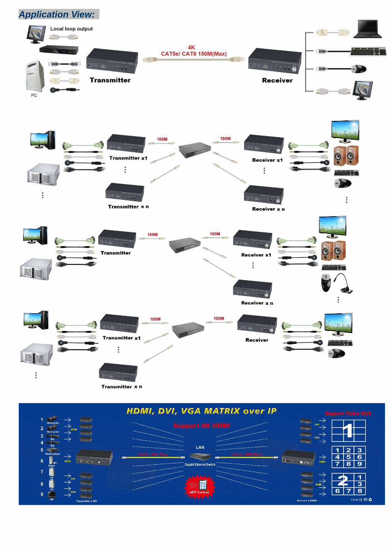
Application View:
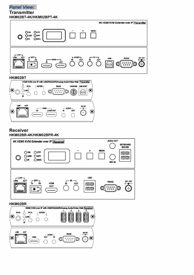
Panel View:
Transmitter HKM02BT-4K/HKM02BPT-4K
HKM02BT
Receiver HKM02BR-4K/HKM02BPR-4K
HKM02BR
Panel Button Function: HKM02B-4K/HKM02BP-4K Button - + Menu
Short Press Reduce Value Increase Value
Menu/Cancel Press together Enter
Press 3 seconds Carry Decomposition
Press 6 seconds Lock/Unlock Button(When no OSD menu)
Press and hold then power on Factory Default Engineering Mode Set Factory Default then enter Engineering Mode HKM02B Button - + - and + together
Short Press Reduce Value Increase Value Enter
Press 3 seconds Carry Decomposition
Menu/Cancel
Press 6 seconds Lock/Unlock Button(When no OSD menu)
Press and hold then power on Factory Default Engineering Mode Set Factory Default then enter Engineering Mode
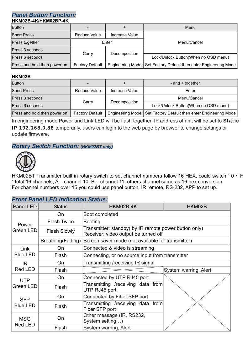
In engineering mode Power and Link LED will be flash together, IP address of unit will be set to Static IP 192.168.0.88 temporarily, users can login to the web page by browser to change settings or update firmware. Rotary Switch Function: (HKM02BT only)
HKM02BT Transmitter built in rotary switch to set channel numbers follow 16 HEX, could switch “ 0 ~ F “ total 16 channels, A = channel 10, B = channel 11, others channel same as 16 hex conversion. For channel numbers over 15 you could use panel button, IR remote, RS-232, APP to set up. Front Panel LED Indication Status: Panel LED Status HKM02B-4K HKM02B
Power Green LED
On Boot completedFlash Twice Booting
Flash Slowly Transmitter: standby( by IR remote power button only) Receiver: video output be turned off
Breathing(Fading) Screen saver mode (not available for transmitter) Link
Blue LED On Connected & video is streaming
Flash Connecting, or no source input from transmitter IR
Red LED On Transmitting /receiving IR signal
Flash System warring, Alert
UTP Green LED
On Connected by UTP RJ45 port
Flash Transmitting /receiving data from UTP RJ45 port
SFP Blue LED
On Connected by Fiber SFP port
Flash Transmitting /receiving data from Fiber SFP port
MSG Red LED
On Other message (IR, RS232, System setting…)
Flash System warring, Alert
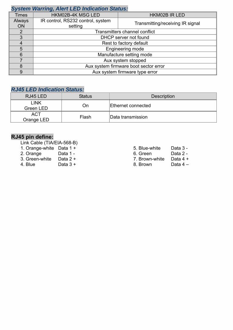
System Warring, Alert LED Indication Status: Times HKM02B-4K MSG LED HKM02B IR LED Always
ON IR control, RS232 control, system
setting Transmitting/receiving IR signal
2 Transmitters channel conflict 3 DHCP server not found 4 Rest to factory default 5 Engineering mode 6 Manufacture setting mode 7 Aux system stopped 8 Aux system firmware boot sector error 9 Aux system firmware type error
RJ45 LED Indication Status: RJ45 LED Status Description
LINK Green LED On Ethernet connected
ACT Orange LED Flash Data transmission
RJ45 pin define: Link Cable (TIA/EIA-568-B) 1. Orange-white Data 1 + 5. Blue-white Data 3 - 2. Orange Data 1 - 6. Green Data 2 - 3. Green-white Data 2 + 7. Brown-white Data 4 + 4. Blue Data 3 + 8. Brown Data 4 –
Cable & Transmission Distance: Link Cable use high quality CAT.5e UTP/STP/FTP or CAT.6 UTP cable Transmission distance will be affected by equipment (Switch HUB), cable quality…etc. When using CAT.5e/CAT.6 cable connect transmitter and receiver directly without Ethernet switch, the maximum transmission distance up to 150M. You can also use model no: SR01 repeater for extended longer distance or using Gigabit Switch hub which support IGMP protocol and Jumbo Frame 8K for signal distribution or extend distance.
System Default Settings: Transmitter / receiver support Unicast and Multicast two mode, default is Multicast. In Multicast mode it could be one to one, one to multi, multi to on or multi to multi applications. The analog audio output of transmitter and input of receiver will be off in this mode, analog audio only from transmitters send to receivers. Unicast mode suitable for one to one or multiple transmitters to one receiver applications. Analog audio bi-direction transmission only in Unicast mode. System default IP setting is Auto IP, it will assign 169.254.X.X (submask 255.255.0.0) to transmitters and receivers, you could also set to DHCP or Static IP, please refer to web setting chapter: IP Setup. We recommend DHCP or Static IP mode in mass deployment to prevent IP conflict problem.
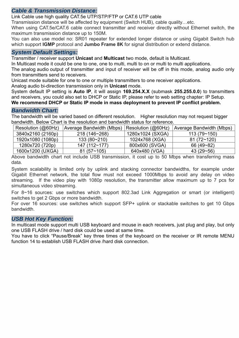
Bandwidth Chart: The bandwidth will be varied based on different resolution. Higher resolution may not request bigger bandwidth. Below Chart is the resolution and bandwidth status for reference.
Resolution (@60Hz) Average Bandwidth (Mbps) Resolution (@60Hz) Average Bandwidth (Mbps)3840x2160 (2160p) 218 (146~268) 1280x1024 (SXGA) 113 (79~150) 1920x1080 (1080p) 133 (80~210) 1024x768 (XGA) 81 (72~120)
1280x720 (720p) 147 (112~177) 800x600 (SVGA) 66 (49~82) 1600x1200 (UXGA) 81 (57~105) 640x480 (VGA) 43 (29~56)
Above bandwidth chart not include USB transmission, it cost up to 50 Mbps when transferring mass data.
System scalability is limited only by uplink and stacking connector bandwidths, for example under Gigabit Ethernet network, the total flow must not exceed 1000Mbps to avoid any delay on video streaming. If the video play with 1080p resolution, the transmitter allow maximum up to 7 pcs for simultaneous video streaming.
For 8~16 sources: use switches which support 802.3ad Link Aggregation or smart (or intelligent) switches to get 2 Gbps or more bandwidth. For over 16 sources: use switches which support SFP+ uplink or stackable switches to get 10 Gbps bandwidth.
USB Hot Key Function: In multicast mode support multi USB keyboard and mouse in each receivers, just plug and play, but only one USB FLASH drive / hard disk could be used at same time. You have to click “Pause/Break” key three times of the keyboard on the receiver or IR remote MENU function 14 to establish USB FLASH drive /hard disk connection.
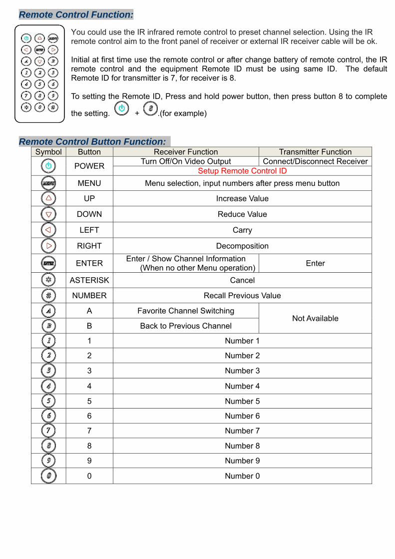
Remote Control Function: You could use the IR infrared remote control to preset channel selection. Using the IR remote control aim to the front panel of receiver or external IR receiver cable will be ok. Initial at first time use the remote control or after change battery of remote control, the IR remote control and the equipment Remote ID must be using same ID. The default Remote ID for transmitter is 7, for receiver is 8. To setting the Remote ID, Press and hold power button, then press button 8 to complete
the setting. + .(for example)
Remote Control Button Function:
Symbol Button Receiver Function Transmitter Function
POWER Turn Off/On Video Output Connect/Disconnect ReceiverSetup Remote Control ID
MENU Menu selection, input numbers after press menu button
UP Increase Value
DOWN Reduce Value
LEFT Carry
RIGHT Decomposition
ENTER Enter / Show Channel Information (When no other Menu operation) Enter
ASTERISK Cancel
NUMBER Recall Previous Value
A Favorite Channel Switching Not Available
B Back to Previous Channel
1 Number 1
2 Number 2
3 Number 3
4 Number 4
5 Number 5
6 Number 6
7 Number 7
8 Number 8
9 Number 9
0 Number 0
Remote Control Operation: Select Channel:
Mode 1: use or or or to select channel and press ENTER to confirm. Mode 2: enter the channel number and press ENTER to confirm the input channel.
Select Menu Function: Mode 1: press MENU then use or or or to select function, press ENTER to confirm. Mode 2: press MENU, then input function number as below, press ENTER to confirm.
Wake Up Receiver: Receiver will enter screen saver mode after 30 seconds if no video input, you could press any button of IR remote or pane to wake up
Turn On/Off Monitor: Press POWER of IR remote or panel button CH- and CH+ together to turn on video output
IR Quick Block: # # #: IR block mode, ignore IR control signal until press any panel button or IR remote * three times * * *: Quit IR block mode
TV Wall Quick Switch: MENU+POWER: IR quick block mode, ignore IR control signal until press any panel button or IR remote * * *
Add Favorite List: MENU+A: Add channel to favorite list in menu, maximum 32 channels.
Remove Favorite List: MENU+B: Remove current channel from favorite list in menu
Transmitter RS232 Mode: MENU+A: Switch to message mode to receive response instead of OSD. MENU+B: Switch to extender mode.
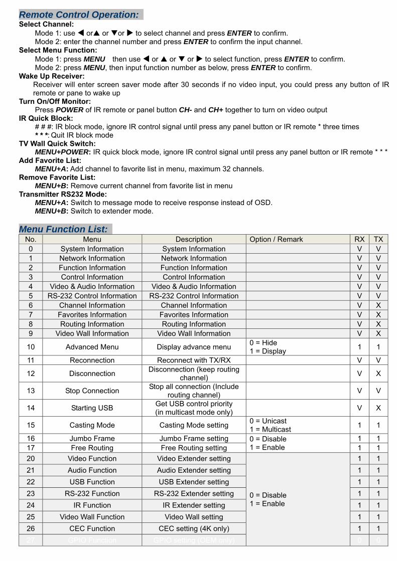
Menu Function List:
No. Menu Description Option / Remark RX TX0 System Information System Information V V 1 Network Information Network Information V V 2 Function Information Function Information V V 3 Control Information Control Information V V 4 Video & Audio Information Video & Audio Information V V 5 RS-232 Control Information RS-232 Control Information V V 6 Channel Information Channel Information V X 7 Favorites Information Favorites Information V X 8 Routing Information Routing Information V X 9 Video Wall Information Video Wall Information V X
10 Advanced Menu Display advance menu 0 = Hide 1 = Display 1 1
11 Reconnection Reconnect with TX/RX V V
12 Disconnection Disconnection (keep routing channel) V X
13 Stop Connection Stop all connection (Include routing channel) V V
14 Starting USB Get USB control priority (in multicast mode only) V X
15 Casting Mode Casting Mode setting 0 = Unicast 1 = Multicast 1 1
16 Jumbo Frame Jumbo Frame setting 0 = Disable 1 = Enable
1 1 17 Free Routing Free Routing setting 1 1 20 Video Function Video Extender setting
0 = Disable 1 = Enable
1 1 21 Audio Function Audio Extender setting 1 1 22 USB Function USB Extender setting 1 1 23 RS-232 Function RS-232 Extender setting 1 1 24 IR Function IR Extender setting 1 1 25 Video Wall Function Video Wall setting 1 1 26 CEC Function CEC setting (4K only) 1 1 27 GPIO Function GPIO setting (OEM only) 0 0
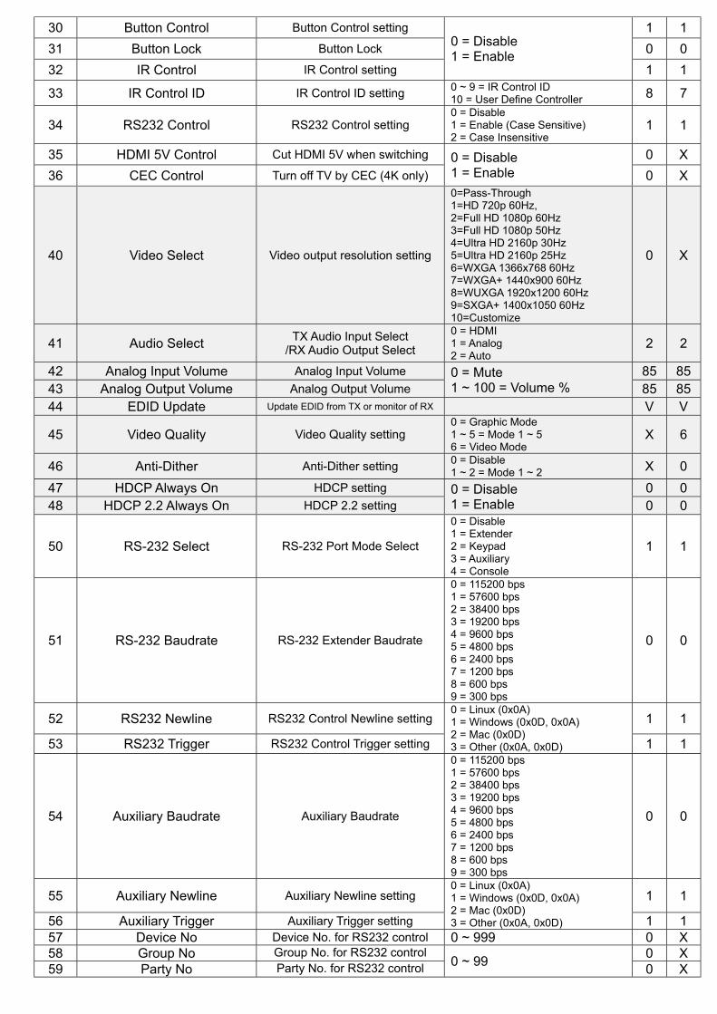
30 Button Control Button Control setting 0 = Disable 1 = Enable
1 1 31 Button Lock Button Lock 0 0 32 IR Control IR Control setting 1 1
33 IR Control ID IR Control ID setting 0 ~ 9 = IR Control ID 10 = User Define Controller 8 7
34 RS232 Control RS232 Control setting 0 = Disable 1 = Enable (Case Sensitive) 2 = Case Insensitive
1 1
35 HDMI 5V Control Cut HDMI 5V when switching 0 = Disable 1 = Enable
0 X 36 CEC Control Turn off TV by CEC (4K only) 0 X
40 Video Select Video output resolution setting
0=Pass-Through 1=HD 720p 60Hz, 2=Full HD 1080p 60Hz 3=Full HD 1080p 50Hz 4=Ultra HD 2160p 30Hz 5=Ultra HD 2160p 25Hz 6=WXGA 1366x768 60Hz 7=WXGA+ 1440x900 60Hz 8=WUXGA 1920x1200 60Hz 9=SXGA+ 1400x1050 60Hz 10=Customize
0 X
41 Audio Select TX Audio Input Select /RX Audio Output Select
0 = HDMI 1 = Analog 2 = Auto
2 2
42 Analog Input Volume Analog Input Volume 0 = Mute 1 ~ 100 = Volume %
85 8543 Analog Output Volume Analog Output Volume 85 8544 EDID Update Update EDID from TX or monitor of RX V V
45 Video Quality Video Quality setting 0 = Graphic Mode 1 ~ 5 = Mode 1 ~ 5 6 = Video Mode
X 6
46 Anti-Dither Anti-Dither setting 0 = Disable 1 ~ 2 = Mode 1 ~ 2 X 0
47 HDCP Always On HDCP setting 0 = Disable 1 = Enable
0 0 48 HDCP 2.2 Always On HDCP 2.2 setting 0 0
50 RS-232 Select RS-232 Port Mode Select
0 = Disable 1 = Extender 2 = Keypad 3 = Auxiliary 4 = Console
1 1
51 RS-232 Baudrate RS-232 Extender Baudrate
0 = 115200 bps 1 = 57600 bps 2 = 38400 bps 3 = 19200 bps 4 = 9600 bps 5 = 4800 bps 6 = 2400 bps 7 = 1200 bps 8 = 600 bps 9 = 300 bps
0 0
52 RS232 Newline RS232 Control Newline setting 0 = Linux (0x0A) 1 = Windows (0x0D, 0x0A) 2 = Mac (0x0D) 3 = Other (0x0A, 0x0D)
1 1
53 RS232 Trigger RS232 Control Trigger setting 1 1
54 Auxiliary Baudrate Auxiliary Baudrate
0 = 115200 bps 1 = 57600 bps 2 = 38400 bps 3 = 19200 bps 4 = 9600 bps 5 = 4800 bps 6 = 2400 bps 7 = 1200 bps 8 = 600 bps 9 = 300 bps
0 0
55 Auxiliary Newline Auxiliary Newline setting 0 = Linux (0x0A) 1 = Windows (0x0D, 0x0A) 2 = Mac (0x0D) 3 = Other (0x0A, 0x0D)
1 1
56 Auxiliary Trigger Auxiliary Trigger setting 1 1 57 Device No Device No. for RS232 control 0 ~ 999 0 X 58 Group No Group No. for RS232 control
0 ~ 99 0 X 59 Party No Party No. for RS232 control 0 X
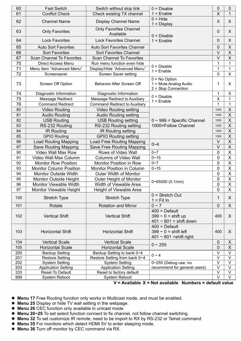
60 Fast Switch Switch without stop link 0 = Disable 1 = Enable
0 0 61 Conflict Check Check existing TX channel X 1
62 Channel Name Display Channel Name 0 = Hide 1 = Display 0 X
63 Only Favorites Only Favorites Channel Available 0 = Disable
1 = Enable
0 X
64 Lock Favorites Lock Favorites Channel 0 X 65 Auto Sort Favorites Auto Sort Favorites Channel 0 X 66 Sort Favorites Sort Favorites Channel V X 67 Scan Channel To Favorites Scan Channel To Favorites V X 70 Direct Access Menu Run menu function even hide
0 = Disable 1 = Enable
1 1 71 Menu Item “Advanced Menu” Display/Hide “Advanced Menu” 1 1 72 Screensaver Screen Saver setting 0 X
73 Screen Off Option Behavior After Screen Off 0 = No Option 1 = Mute Analog Audio 2 = Stop Connection
1 X
74 Diagnostic Information Diagnostic Information 0 = Disable 1 = Enable
1 X 75 Message Redirect Message Redirect to Auxiliary X 1 76 Command Redirect Command Redirect to Auxiliary 1 1 80 Video Routing Video Routing setting
0 ~ 999 = Specific Channel 1000=Follow Channel
1000 X 81 Audio Routing Audio Routing setting 1000 X 82 USB Routing USB Routing setting 1000 X 83 RS-232 Routing RS-232 Routing setting 1000 X 84 IR Routing IR Routing setting 1000 X 85 GPIO Routing GPIO Routing setting 1000 X 86 Load Routing Mapping Load Free Routing Mapping 0~4 V X 87 Save Routing Mapping Save Free Routing Mapping V X 90 Video Wall Max Row Rows of Video Wall 0~7 0 X 91 Video Wall Max Column Columns of Video Wall 0~15 0 X 92 Monitor Row Position Monitor Position in Row 0~7 0 X 93 Monitor Column Position Monitor Position in Column 0~15 0 X 94 Monitor Outside Width Outer Width of Monitor
0~65000 (0.1mm)
0 X 95 Monitor Outside Height Outer Height of Monitor 0 X 96 Monitor Viewable Width Width of Viewable Area 0 X 97 Monitor Viewable Height Height of Viewable Area 0 X
100 Stretch Type Stretch Type 0 = Stretch Out 1 = Fit In 1 X
101 Rotate Rotation and Mirror 0 ~ 7 0 X
102 Vertical Shift Vertical Shift 400 = Default 399 ~ 0 = shift up 401 ~ 801 = shift down
400 X
103 Horizontal Shift Horizontal Shift 400 = Default 399 ~ 0 = shift left 401 ~ 801 =shift right
400 X
104 Vertical Scale Vertical Scale 0 ~ 255 0 X 105 Horizontal Scale Horizontal Scale 0 X 200 Backup Setting Backup Setting to bank 0~4 0 ~ 4 V V 201 Restore Setting Restore Setting from bank 0~4 V V 202 System Setting System Setting 0~255 (Debug use, no
recommend for general users) V V
203 Application Setting Application Setting V V 333 Reset To Default Reset to factory default V V 999 System Reboot System Reboot V V
V = Available X = Not available Numbers = default value
Menu 17 Free Routing function only works in Multicast mode, and must be enabled. Menu 25 Display or hide TV wall setting in the webpage. Menu 26 CEC function only available in unicast mode. Menu 20~25 To set select function connect to fix channel, not follow channel switching. Menu 32 To set customize IR remote, need to be import to RX by RS-232 or Telnet command Menu 35 For monitors which detect HDMI 5V to enter sleeping mode. Menu 36 Turn off monitor by CEC command via RX.

Menu 40 Customize resolution need to be setup by RS-232 command or web page Menu 44 Use default EDID at TX side, copy monitor EDID at RX side. Menu 47~48 Monitor HDCP version setting, with incorrect HDCP version setting it will show black screen.
HDCP Always On HDCP 2.2 Always On Description Disable Disable HDCP version follow source and Stream Type of content Enable Disable Monitor support HDCP 1.4
Don’t Care Enable Monitor support HDCP 2.2 Menu 50 Extender = RS-232 extender, Keypad = for RS-232 keypad or number key in terminal software,
Auxiliary = auxiliary mode debug, Console = system console debug Menu 60 Fast Switch mode works best when: resolution, frame rate, scan mode (interlaced/non-interlaced),
color depth, color space, interface (HDMI/DVI), HDCP mode (ON/OFF) all above are the same. Disable: Stop link before channel switch, is will show black screen between switching, if switch to the channel which not exist it will show diagnostic Information. Enable: Keep link when channel switch, if switch to the channel which not exist may cause screen freeze 1~2 seconds then show diagnostic Information.
Menu 61 Conflict Check will check existing TX channel number at booting, reconnection or before switching. Menu 62 Channel Name will show full name instead of number only, the position of channel name is center of
screen. Channel name can set by RS232 command or import from telnet port. Menu 75 Message Redirect forward MENU message to TX RS232 port (Auxiliary mode) instead OSD. Menu 76 Command Redirect run RS232 command from Web or telnet port (Auxiliary mode). Menu 80~85 Fix selected function not follow the channel, only available when free routing enabled. Menu 90~103 Only available when video wall function enabled.. Keypad Function: You can use RS-232 Keypad or terminal program with number key to emulate IR remote operation. Before using RS-232 keypad you have to select Keypad by Menu 56 RS-232 Select, and set RS-232 baudrate by Menu 60 Auxiliary Baudrate.
Key Description 0~9 Enter number + Increase value - Reduce value . or # Previous value Enter Confirm * or Esc or Clear Cancel / Call MENU Press Clear four times then press Enter Call MENU
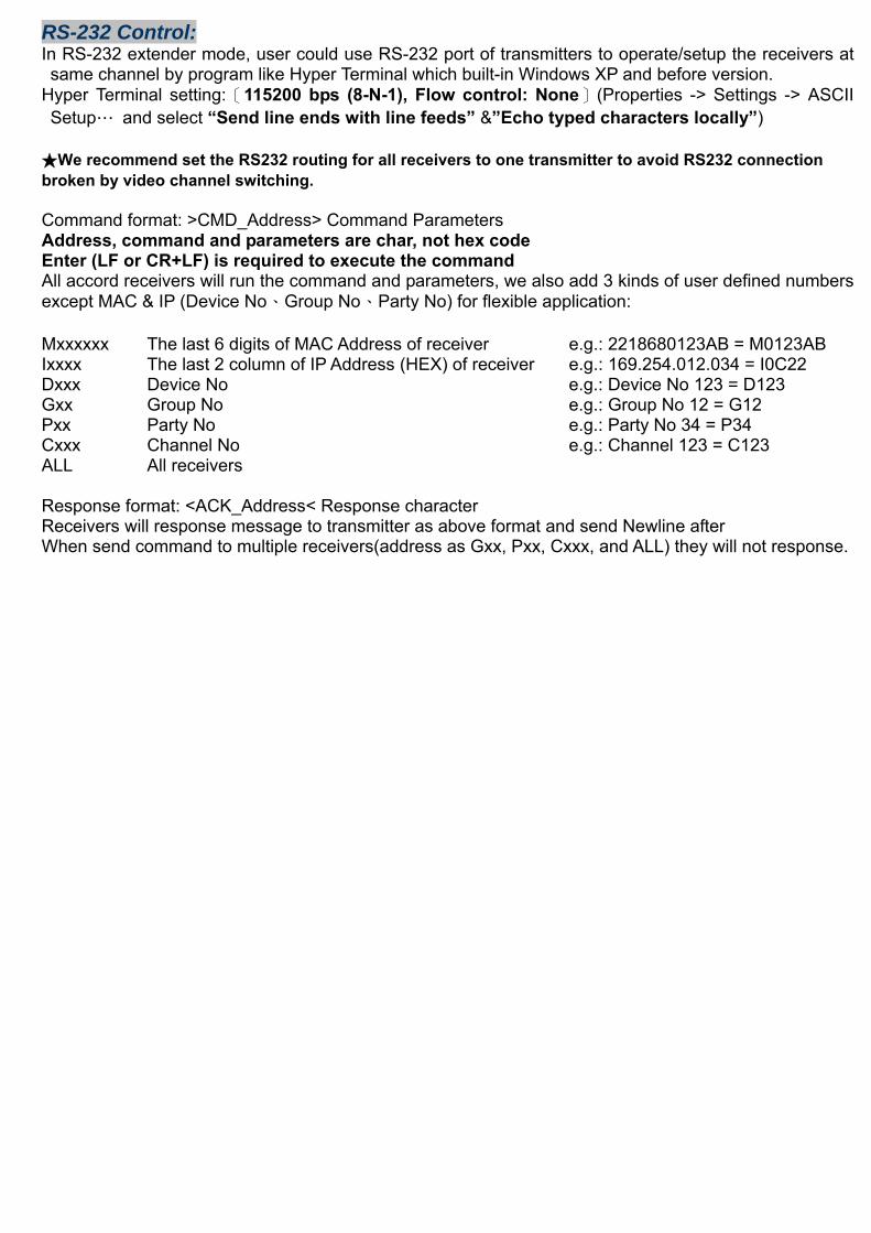
RS-232 Control: In RS-232 extender mode, user could use RS-232 port of transmitters to operate/setup the receivers at same channel by program like Hyper Terminal which built-in Windows XP and before version.
Hyper Terminal setting:〔115200 bps (8-N-1), Flow control: None〕(Properties -> Settings -> ASCII Setup… and select “Send line ends with line feeds” &”Echo typed characters locally”)
★We recommend set the RS232 routing for all receivers to one transmitter to avoid RS232 connection broken by video channel switching. Command format: >CMD_Address> Command Parameters Address, command and parameters are char, not hex code Enter (LF or CR+LF) is required to execute the command All accord receivers will run the command and parameters, we also add 3 kinds of user defined numbers except MAC & IP (Device No、Group No、Party No) for flexible application: Mxxxxxx The last 6 digits of MAC Address of receiver e.g.: 2218680123AB = M0123AB Ixxxx The last 2 column of IP Address (HEX) of receiver e.g.: 169.254.012.034 = I0C22 Dxxx Device No e.g.: Device No 123 = D123 Gxx Group No e.g.: Group No 12 = G12 Pxx Party No e.g.: Party No 34 = P34 Cxxx Channel No e.g.: Channel 123 = C123 ALL All receivers Response format: <ACK_Address< Response character Receivers will response message to transmitter as above format and send Newline after When send command to multiple receivers(address as Gxx, Pxx, Cxxx, and ALL) they will not response.
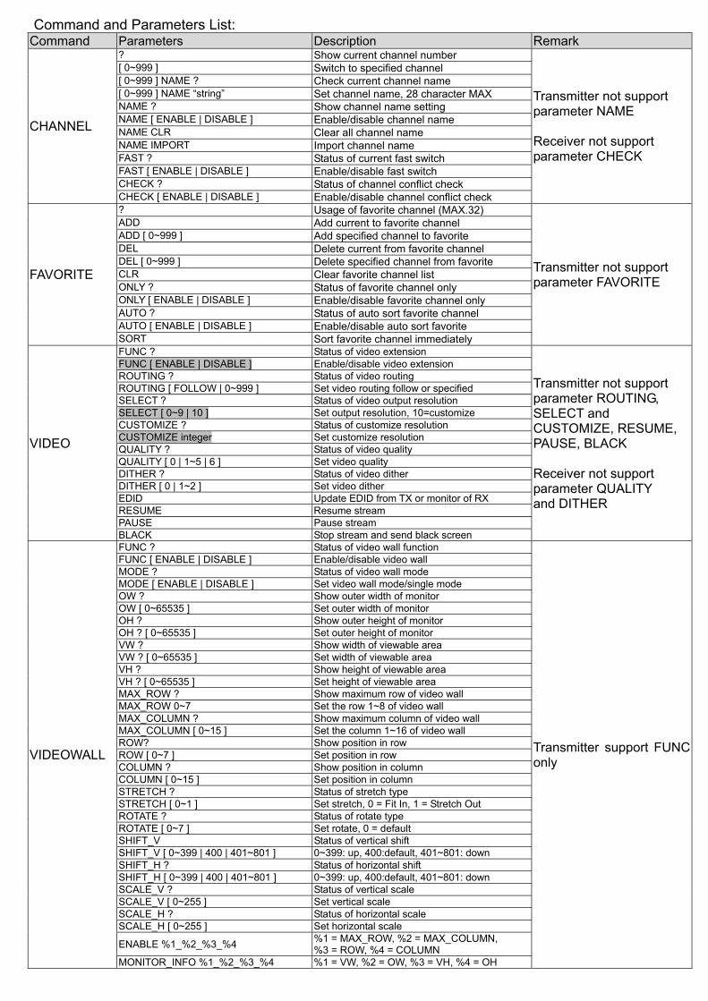
Command and Parameters List: Command Parameters Description Remark
CHANNEL
? Show current channel number
Transmitter not support parameter NAME Receiver not support parameter CHECK
[ 0~999 ] Switch to specified channel [ 0~999 ] NAME ? Check current channel name [ 0~999 ] NAME “string” Set channel name, 28 character MAX NAME ? Show channel name setting NAME [ ENABLE | DISABLE ] Enable/disable channel name NAME CLR Clear all channel name NAME IMPORT Import channel name FAST ? Status of current fast switch FAST [ ENABLE | DISABLE ] Enable/disable fast switch CHECK ? Status of channel conflict check CHECK [ ENABLE | DISABLE ] Enable/disable channel conflict check
FAVORITE
? Usage of favorite channel (MAX.32)
Transmitter not support parameter FAVORITE
ADD Add current to favorite channel ADD [ 0~999 ] Add specified channel to favorite DEL Delete current from favorite channel DEL [ 0~999 ] Delete specified channel from favorite CLR Clear favorite channel list ONLY ? Status of favorite channel only ONLY [ ENABLE | DISABLE ] Enable/disable favorite channel only AUTO ? Status of auto sort favorite channel AUTO [ ENABLE | DISABLE ] Enable/disable auto sort favorite SORT Sort favorite channel immediately
VIDEO
FUNC ? Status of video extension
Transmitter not support parameter ROUTING, SELECT and CUSTOMIZE, RESUME, PAUSE, BLACK Receiver not support parameter QUALITY and DITHER
FUNC [ ENABLE | DISABLE ] Enable/disable video extension ROUTING ? Status of video routing ROUTING [ FOLLOW | 0~999 ] Set video routing follow or specified SELECT ? Status of video output resolution SELECT [ 0~9 | 10 ] Set output resolution, 10=customize CUSTOMIZE ? Status of customize resolution CUSTOMIZE integer Set customize resolution QUALITY ? Status of video quality QUALITY [ 0 | 1~5 | 6 ] Set video quality DITHER ? Status of video dither DITHER [ 0 | 1~2 ] Set video dither EDID Update EDID from TX or monitor of RX RESUME Resume stream PAUSE Pause stream BLACK Stop stream and send black screen
VIDEOWALL
FUNC ? Status of video wall function
Transmitter support FUNC only
FUNC [ ENABLE | DISABLE ] Enable/disable video wall MODE ? Status of video wall mode MODE [ ENABLE | DISABLE ] Set video wall mode/single mode OW ? Show outer width of monitor OW [ 0~65535 ] Set outer width of monitor OH ? Show outer height of monitor OH ? [ 0~65535 ] Set outer height of monitor VW ? Show width of viewable area VW ? [ 0~65535 ] Set width of viewable area VH ? Show height of viewable area VH ? [ 0~65535 ] Set height of viewable area MAX_ROW ? Show maximum row of video wall MAX_ROW 0~7 Set the row 1~8 of video wall MAX_COLUMN ? Show maximum column of video wall MAX_COLUMN [ 0~15 ] Set the column 1~16 of video wall ROW? Show position in row ROW [ 0~7 ] Set position in row COLUMN ? Show position in column COLUMN [ 0~15 ] Set position in column STRETCH ? Status of stretch type STRETCH [ 0~1 ] Set stretch, 0 = Fit In, 1 = Stretch Out ROTATE ? Status of rotate type ROTATE [ 0~7 ] Set rotate, 0 = default SHIFT_V Status of vertical shift SHIFT_V [ 0~399 | 400 | 401~801 ] 0~399: up, 400:default, 401~801: down SHIFT_H ? Status of horizontal shift SHIFT_H [ 0~399 | 400 | 401~801 ] 0~399: up, 400:default, 401~801: down SCALE_V ? Status of vertical scale SCALE_V [ 0~255 ] Set vertical scale SCALE_H ? Status of horizontal scale SCALE_H [ 0~255 ] Set horizontal scale
ENABLE %1_%2_%3_%4 %1 = MAX_ROW, %2 = MAX_COLUMN, %3 = ROW, %4 = COLUMN
MONITOR_INFO %1_%2_%3_%4 %1 = VW, %2 = OW, %3 = VH, %4 = OH
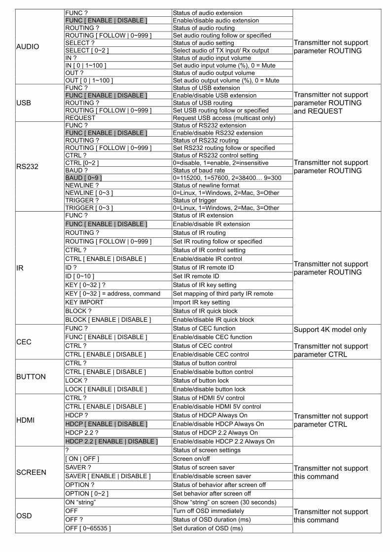
AUDIO
FUNC ? Status of audio extension
Transmitter not support parameter ROUTING
FUNC [ ENABLE | DISABLE ] Enable/disable audio extension ROUTING ? Status of audio routing ROUTING [ FOLLOW | 0~999 ] Set audio routing follow or specified SELECT ? Status of audio setting SELECT [ 0~2 ] Select audio of TX input/ Rx output IN ? Status of audio input volume IN [ 0 | 1~100 ] Set audio input volume (%), 0 = Mute OUT ? Status of audio output volume OUT [ 0 | 1~100 ] Set audio output volume (%), 0 = Mute
USB
FUNC ? Status of USB extension Transmitter not support parameter ROUTING and REQUEST
FUNC [ ENABLE | DISABLE ] Enable/disable USB extension ROUTING ? Status of USB routing ROUTING [ FOLLOW | 0~999 ] Set USB routing follow or specified REQUEST Request USB access (multicast only)
RS232
FUNC ? Status of RS232 extension
Transmitter not support parameter ROUTING
FUNC [ ENABLE | DISABLE ] Enable/disable RS232 extension ROUTING ? Status of RS232 routing ROUTING [ FOLLOW | 0~999 ] Set RS232 routing follow or specified CTRL ? Status of RS232 control setting CTRL [0~2 ] 0=disable, 1=enable, 2=insensitive BAUD ? Status of baud rate BAUD [ 0~9 ] 0=115200, 1=57600, 2=38400… 9=300 NEWLINE ? Status of newline format NEWLINE [ 0~3 ] 0=Linux, 1=Windows, 2=Mac, 3=Other TRIGGER ? Status of trigger TRIGGER [ 0~3 ] 0=Linux, 1=Windows, 2=Mac, 3=Other
IR
FUNC ? Status of IR extension
Transmitter not support parameter ROUTING
FUNC [ ENABLE | DISABLE ] Enable/disable IR extension ROUTING ? Status of IR routing ROUTING [ FOLLOW | 0~999 ] Set IR routing follow or specified CTRL ? Status of IR control setting CTRL [ ENABLE | DISABLE ] Enable/disable IR control ID ? Status of IR remote ID ID [ 0~10 ] Set IR remote ID KEY [ 0~32 ] ? Status of IR key setting KEY [ 0~32 ] = address, command Set mapping of third party IR remote KEY IMPORT Import IR key setting BLOCK ? Status of IR quick block BLOCK [ ENABLE | DISABLE ] Enable/disable IR quick block
CEC
FUNC ? Status of CEC function Support 4K model only Transmitter not support parameter CTRL
FUNC [ ENABLE | DISABLE ] Enable/disable CEC function CTRL ? Status of CEC control CTRL [ ENABLE | DISABLE ] Enable/disable CEC control
BUTTON
CTRL ? Status of button control CTRL [ ENABLE | DISABLE ] Enable/disable button control LOCK ? Status of button lock LOCK [ ENABLE | DISABLE ] Enable/disable button lock
HDMI
CTRL ? Status of HDMI 5V control
Transmitter not support parameter CTRL
CTRL [ ENABLE | DISABLE ] Enable/disable HDMI 5V control HDCP ? Status of HDCP Always On HDCP [ ENABLE | DISABLE ] Enable/disable HDCP Always On HDCP 2.2 ? Status of HDCP 2.2 Always On HDCP 2.2 [ ENABLE | DISABLE ] Enable/disable HDCP 2.2 Always On
SCREEN
? Status of screen settings
Transmitter not support this command
[ ON | OFF ] Screen on/off SAVER ? Status of screen saver SAVER [ ENABLE | DISABLE ] Enable/disable screen saver OPTION ? Status of behavior after screen off OPTION [ 0~2 ] Set behavior after screen off
OSD
ON “string” Show “string” on screen (30 seconds) Transmitter not support this command
OFF Turn off OSD immediately OFF ? Status of OSD duration (ms) OFF [ 0~65535 ] Set duration of OSD (ms)
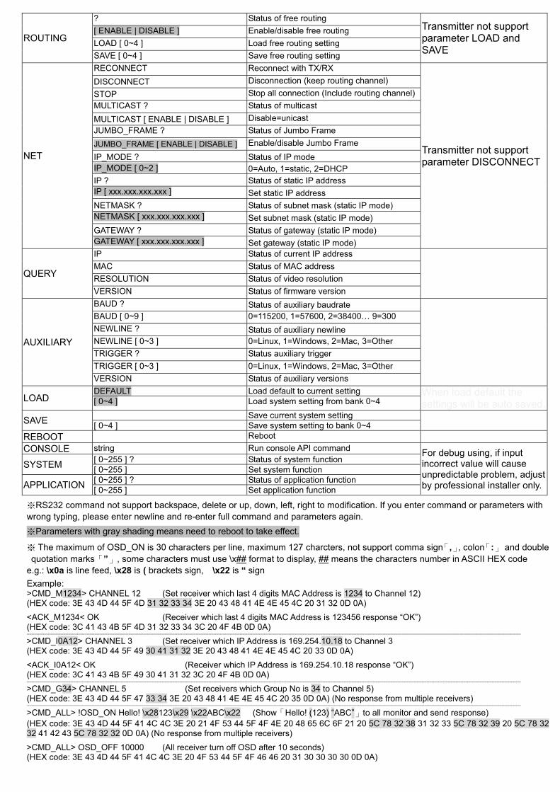
ROUTING
? Status of free routing Transmitter not support parameter LOAD and SAVE
[ ENABLE | DISABLE ] Enable/disable free routing LOAD [ 0~4 ] Load free routing setting SAVE [ 0~4 ] Save free routing setting
NET
RECONNECT Reconnect with TX/RX
Transmitter not support parameter DISCONNECT
DISCONNECT Disconnection (keep routing channel) STOP Stop all connection (Include routing channel) MULTICAST ? Status of multicast MULTICAST [ ENABLE | DISABLE ] Disable=unicast JUMBO_FRAME ? Status of Jumbo Frame JUMBO_FRAME [ ENABLE | DISABLE ] Enable/disable Jumbo Frame IP_MODE ? Status of IP modeIP_MODE [ 0~2 ] 0=Auto, 1=static, 2=DHCPIP ? Status of static IP address IP [ xxx.xxx.xxx.xxx ] Set static IP address NETMASK ? Status of subnet mask (static IP mode) NETMASK [ xxx.xxx.xxx.xxx ] Set subnet mask (static IP mode) GATEWAY ? Status of gateway (static IP mode) GATEWAY [ xxx.xxx.xxx.xxx ] Set gateway (static IP mode)
QUERY
IP Status of current IP address MAC Status of MAC address RESOLUTION Status of video resolution VERSION Status of firmware version
AUXILIARY
BAUD ? Status of auxiliary baudrate BAUD [ 0~9 ] 0=115200, 1=57600, 2=38400… 9=300 NEWLINE ? Status of auxiliary newline NEWLINE [ 0~3 ] 0=Linux, 1=Windows, 2=Mac, 3=Other TRIGGER ? Status auxiliary trigger TRIGGER [ 0~3 ] 0=Linux, 1=Windows, 2=Mac, 3=Other VERSION Status of auxiliary versions
LOAD DEFAULT Load default to current setting When load default the
settings will be auto saved.[ 0~4 ] Load system setting from bank 0~4
SAVE Save current system setting [ 0~4 ] Save system setting to bank 0~4
REBOOT Reboot CONSOLE string Run console API command For debug using, if input
incorrect value will cause unpredictable problem, adjust by professional installer only.
SYSTEM [ 0~255 ] ? Status of system function [ 0~255 ] Set system function
APPLICATION [ 0~255 ] ? Status of application function [ 0~255 ] Set application function
※RS232 command not support backspace, delete or up, down, left, right to modification. If you enter command or parameters with wrong typing, please enter newline and re-enter full command and parameters again.
※Parameters with gray shading means need to reboot to take effect.
※ The maximum of OSD_ON is 30 characters per line, maximum 127 charcters, not support comma sign「,」, colon「:」 and double quotation marks「”」, some characters must use \x## format to display, ## means the characters number in ASCII HEX code
e.g.: \x0a is line feed, \x28 is ( brackets sign, \x22 is “ sign
Example: >CMD_M1234> CHANNEL 12 (Set receiver which last 4 digits MAC Address is 1234 to Channel 12) (HEX code: 3E 43 4D 44 5F 4D 31 32 33 34 3E 20 43 48 41 4E 4E 45 4C 20 31 32 0D 0A)
<ACK_M1234< OK (Receiver which last 4 digits MAC Address is 123456 response “OK”) (HEX code: 3C 41 43 4B 5F 4D 31 32 33 34 3C 20 4F 4B 0D 0A) ----------------------------------------------------------------------------------------------------------------------------------------------------------------------------------------------------------------------------------------------------------------------------------------------------------------------------------------------------------------------------------------------------------
>CMD_I0A12> CHANNEL 3 (Set receiver which IP Address is 169.254.10.18 to Channel 3 (HEX code: 3E 43 4D 44 5F 49 30 41 31 32 3E 20 43 48 41 4E 4E 45 4C 20 33 0D 0A)
<ACK_I0A12< OK (Receiver which IP Address is 169.254.10.18 response “OK”) (HEX code: 3C 41 43 4B 5F 49 30 41 31 32 3C 20 4F 4B 0D 0A) ----------------------------------------------------------------------------------------------------------------------------------------------------------------------------------------------------------------------------------------------------------------------------------------------------------------------------------------------------------------------------------------------------------
>CMD_G34> CHANNEL 5 (Set receivers which Group No is 34 to Channel 5) (HEX code: 3E 43 4D 44 5F 47 33 34 3E 20 43 48 41 4E 4E 45 4C 20 35 0D 0A) (No response from multiple receivers) ----------------------------------------------------------------------------------------------------------------------------------------------------------------------------------------------------------------------------------------------------------------------------------------------------------------------------------------------------------------------------------------------------------
>CMD_ALL> !OSD_ON Hello! \x28123\x29 \x22ABC\x22 (Show「Hello! (123) “ABC”」to all monitor and send response) (HEX code: 3E 43 4D 44 5F 41 4C 4C 3E 20 21 4F 53 44 5F 4F 4E 20 48 65 6C 6F 21 20 5C 78 32 38 31 32 33 5C 78 32 39 20 5C 78 32 32 41 42 43 5C 78 32 32 0D 0A) (No response from multiple receivers)
>CMD_ALL> OSD_OFF 10000 (All receiver turn off OSD after 10 seconds) (HEX code: 3E 43 4D 44 5F 41 4C 4C 3E 20 4F 53 44 5F 4F 46 46 20 31 30 30 30 30 0D 0A)
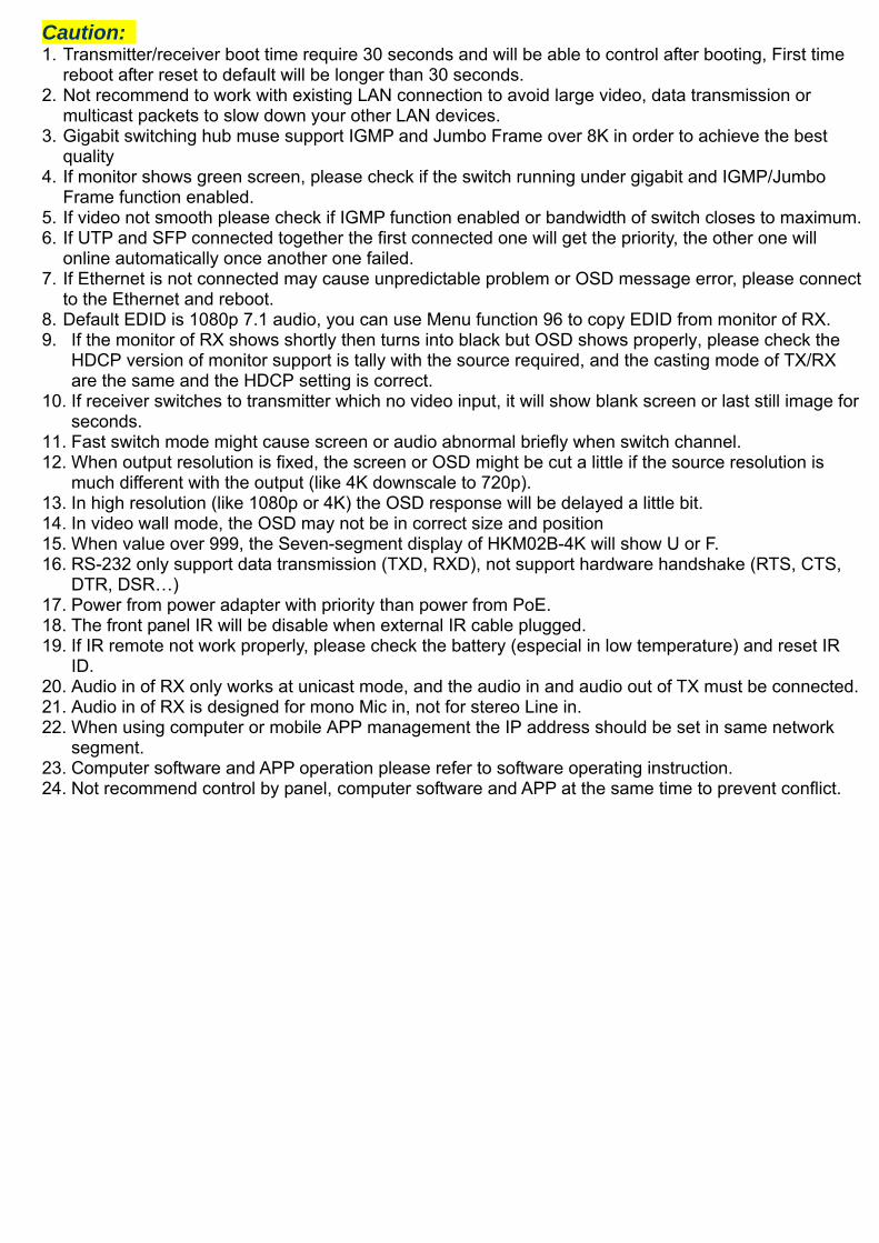
Caution: 1. Transmitter/receiver boot time require 30 seconds and will be able to control after booting, First time
reboot after reset to default will be longer than 30 seconds. 2. Not recommend to work with existing LAN connection to avoid large video, data transmission or
multicast packets to slow down your other LAN devices. 3. Gigabit switching hub muse support IGMP and Jumbo Frame over 8K in order to achieve the best
quality 4. If monitor shows green screen, please check if the switch running under gigabit and IGMP/Jumbo
Frame function enabled. 5. If video not smooth please check if IGMP function enabled or bandwidth of switch closes to maximum. 6. If UTP and SFP connected together the first connected one will get the priority, the other one will
online automatically once another one failed. 7. If Ethernet is not connected may cause unpredictable problem or OSD message error, please connect
to the Ethernet and reboot. 8. Default EDID is 1080p 7.1 audio, you can use Menu function 96 to copy EDID from monitor of RX. 9. If the monitor of RX shows shortly then turns into black but OSD shows properly, please check the
HDCP version of monitor support is tally with the source required, and the casting mode of TX/RX are the same and the HDCP setting is correct.
10. If receiver switches to transmitter which no video input, it will show blank screen or last still image for seconds.
11. Fast switch mode might cause screen or audio abnormal briefly when switch channel. 12. When output resolution is fixed, the screen or OSD might be cut a little if the source resolution is
much different with the output (like 4K downscale to 720p). 13. In high resolution (like 1080p or 4K) the OSD response will be delayed a little bit. 14. In video wall mode, the OSD may not be in correct size and position 15. When value over 999, the Seven-segment display of HKM02B-4K will show U or F. 16. RS-232 only support data transmission (TXD, RXD), not support hardware handshake (RTS, CTS,
DTR, DSR…) 17. Power from power adapter with priority than power from PoE. 18. The front panel IR will be disable when external IR cable plugged. 19. If IR remote not work properly, please check the battery (especial in low temperature) and reset IR
ID. 20. Audio in of RX only works at unicast mode, and the audio in and audio out of TX must be connected. 21. Audio in of RX is designed for mono Mic in, not for stereo Line in. 22. When using computer or mobile APP management the IP address should be set in same network
segment. 23. Computer software and APP operation please refer to software operating instruction. 24. Not recommend control by panel, computer software and APP at the same time to prevent conflict.
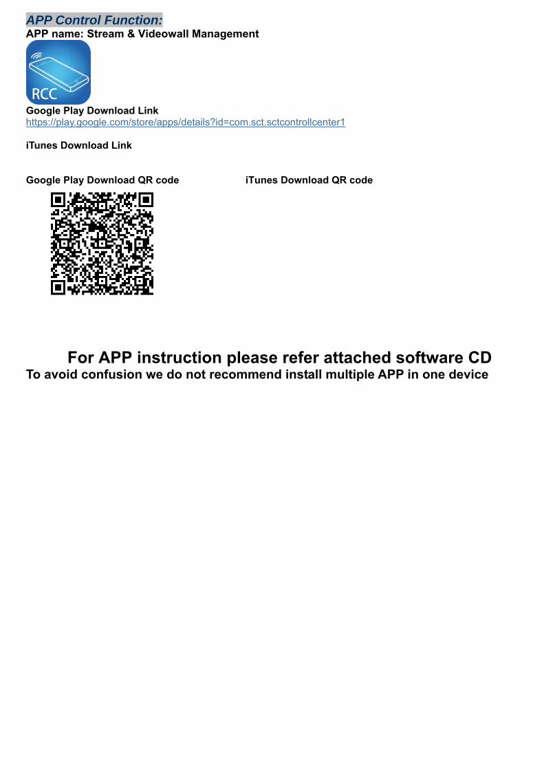
APP Control Function: APP name: Stream & Videowall Management
Google Play Download Link https://play.google.com/store/apps/details?id=com.sct.sctcontrollcenter1 iTunes Download Link Google Play Download QR code iTunes Download QR code
For APP instruction please refer attached software CD To avoid confusion we do not recommend install multiple APP in one device
Web Setting Function: System provide detail settings over web browser, you could input the IP address of transmitter / receiver at link column of browser if you know the exact IP address of them. How to get the IP address of receiver: 1. Connect monitor with receiver, local IP shows on right bottom screen when receiver booting or
transmitter not connected( or no video input) 2. Press remote control button MENU, 1, ENTER (Network Information), it will shows the receiver IP
Address on screen
How to get the IP address of transmitter: 1. Connect monitor with receiver, connect receiver with transmitter and set in the same
channel, remote IP shows on right bottom screen when receiver booting or no video input from transmitter
Set IP address of transmitter/receiver by command:
Press and hold panel button “+” then power on to set factory default then enter engineering mode. In engineering mode Power and Link LED will be flash together, IP address of unit will be set to Static IP 192.168.0.88 temporarily, login to the web page by browser and change IP settings in API commands column as below(x can be one of numbers 1~254):
astparam s ip_mode static
astparam s ipaddr 169.254.x.x
astparam s netmask 255.255.0.0
astparam save
Commands can be applied one by one, or connected them by “;” to apply at once as below:
astparam s ip_mode static;astparam s ipaddr 169.254.x.x;astparam s netmask 255.255.0.0;astparam save
Also you could use private IP address/subnet mask you preferred like 192.168.x.x/255.255.255.0
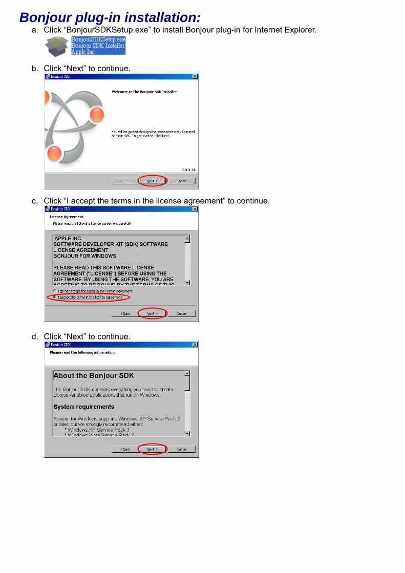
Bonjour plug-in installation: a. Click “BonjourSDKSetup.exe” to install Bonjour plug-in for Internet Explorer.
b. Click “Next” to continue.
c. Click “I accept the terms in the license agreement” to continue.
d. Click “Next” to continue.
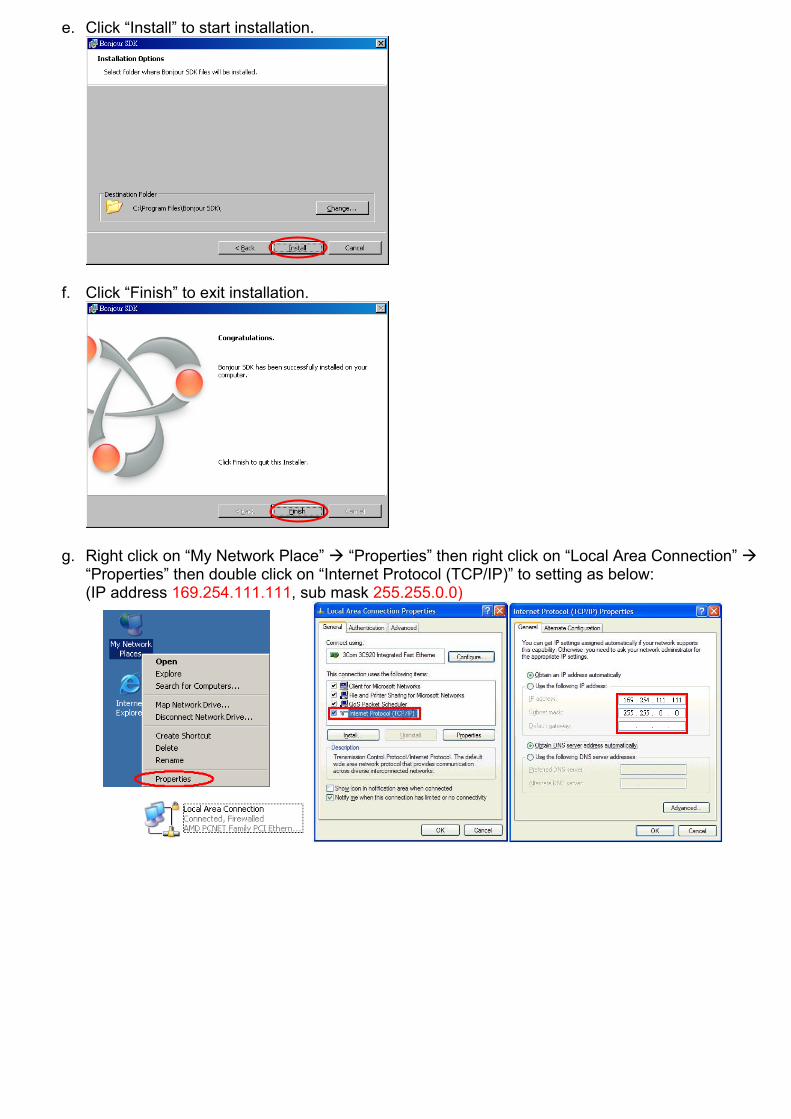
e. Click “Install” to start installation.
f. Click “Finish” to exit installation.
g. Right click on “My Network Place” “Properties” then right click on “Local Area Connection” “Properties” then double click on “Internet Protocol (TCP/IP)” to setting as below: (IP address 169.254.111.111, sub mask 255.255.0.0)

Login in to the web setting: Use CAT5 cable to connect transmitter/receiver RJ45 port to PC LAN port, direct input known IP address of TX/RX, or open IE browser then select View Explorer Bars Bonjour.
Double click on “HTTP on ast3-tx-xxxx(x= channel of transmitter)” or “HTTP on ast3-rx-xxxxxxxxxxxx (x= MAC address of receiver)”, it will pop up web setup in Bonjour windows as below:
Click Network page you will see the IP address of transmitter/receiver
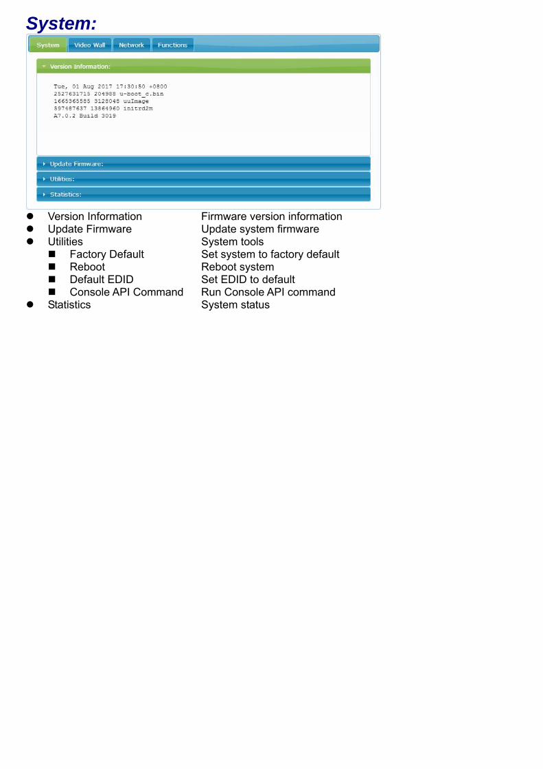
System:
Version Information Firmware version information Update Firmware Update system firmware Utilities System tools
Factory Default Set system to factory default Reboot Reboot system Default EDID Set EDID to default Console API Command Run Console API command
Statistics System status
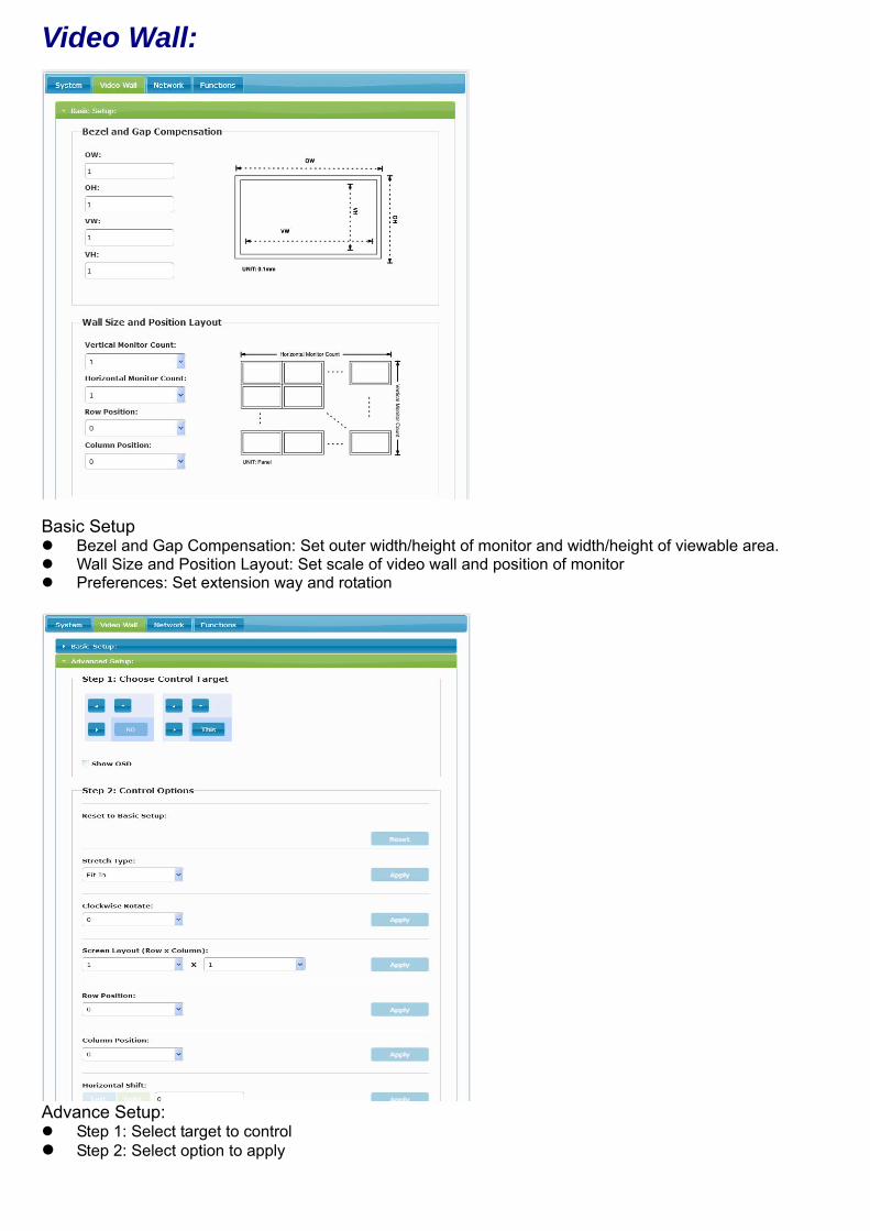
Video Wall:
Basic Setup Bezel and Gap Compensation: Set outer width/height of monitor and width/height of viewable area. Wall Size and Position Layout: Set scale of video wall and position of monitor Preferences: Set extension way and rotation
Advance Setup: Step 1: Select target to control Step 2: Select option to apply
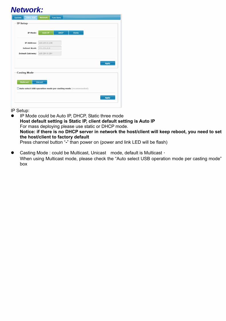
Network:
IP Setup: IP Mode could be Auto IP, DHCP, Static three mode
Host default setting is Static IP, client default setting is Auto IP For mass deploying please use static or DHCP mode. Notice: if there is no DHCP server in network the host/client will keep reboot, you need to set the host/client to factory default Press channel button “-” than power on (power and link LED will be flash)
Casting Mode : could be Multicast, Unicast mode, default is Multicast, When using Multicast mode, please check the “Auto select USB operation mode per casting mode” box
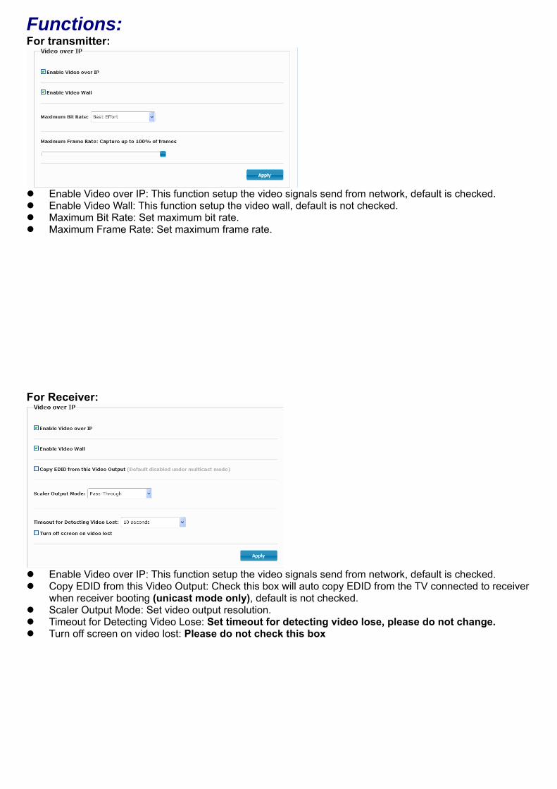
Functions: For transmitter:
Enable Video over IP: This function setup the video signals send from network, default is checked. Enable Video Wall: This function setup the video wall, default is not checked. Maximum Bit Rate: Set maximum bit rate. Maximum Frame Rate: Set maximum frame rate. For Receiver:
Enable Video over IP: This function setup the video signals send from network, default is checked. Copy EDID from this Video Output: Check this box will auto copy EDID from the TV connected to receiver
when receiver booting (unicast mode only), default is not checked. Scaler Output Mode: Set video output resolution. Timeout for Detecting Video Lose: Set timeout for detecting video lose, please do not change. Turn off screen on video lost: Please do not check this box
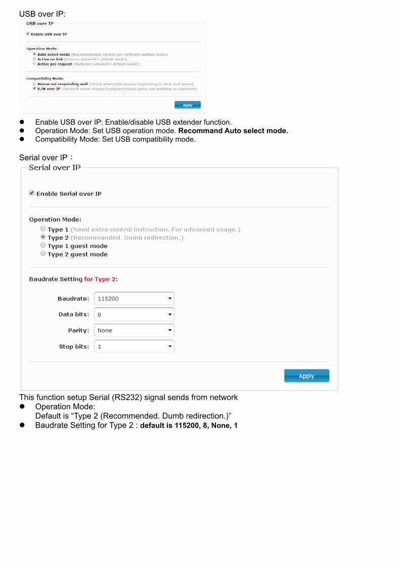
USB over IP:
Enable USB over IP: Enable/disable USB extender function. Operation Mode: Set USB operation mode. Recommand Auto select mode. Compatibility Mode: Set USB compatibility mode. Serial over IP:
This function setup Serial (RS232) signal sends from network Operation Mode:
Default is “Type 2 (Recommended. Dumb redirection.)” Baudrate Setting for Type 2 : default is 115200, 8, None, 1

Package: HKM02BT-4K Package Include: Transmitter x 1 USB A to B cable x 1 IR emitter cable x 1 IR receiver cable x 1 DC 12V 1.5Amp power adapter x 1 HKM02BR-4K Package Include: Receiver x 1 IR emitter cable x 1 IR receiver cable x 1 IR remote control x1 DC 12V 1.5Amp power adapter x 1 HKM02BPT-4K Package Include: Transmitter x 1 USB A to B cable x 1 IR emitter cable x 1 IR receiver cable x 1 HKM02BPR-4K Package Include: Receiver x 1 IR emitter cable x 1 IR receiver cable x 1 IR remote control x1 HKM02BT Package Include: Transmitter x 1 USB A to B cable x 1 IR emitter cable x 1 DC 5V 2Amp power adapter x 1 HKM02BR Package Include: Receiver x 1 IR emitter cable x 1 IR remote control x1 DC 5V 2Amp power adapter x 1
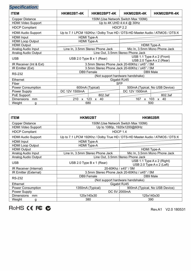
Specification: ITEM HKM02BT-4K HKM02BPT-4K HKM02BR-4K HKM02BPR-4K Copper Distance 150M (Use Network Switch Max 100M) HDMI Video Support Up to 4K UHD 4:4:4 @ 30Hz HDCP Compliant HDCP 2.2 HDMI Audio Support Up to 7.1 LPCM 192Khz / Dolby True HD / DTS-HD Master Audio / ATMOS / DTS:X HDMI Input HDMI Type-A HDMI Loop Output HDMI Type-A HDMI Output HDMI Type-A Analog Audio Input Line In, 3.5mm Stereo Phone Jack Mic In, 3.5mm Mono Phone Jack Analog Audio Output Line Out, 3.5mm Stereo Phone Jack
USB USB 2.0 Type B x 1 (Rear) USB 1.1 Type A x 2 (Front) USB 2.0 Type A x 2 (Rear)
IR Receiver (Int & Ext) 3.5mm Stereo Phone Jack 20-60Khz / ±45° / 5M IR Emitter (Ext) 3.5mm Stereo Phone Jack 20-60Khz / ±45° / 5M
RS-232 DB9 Female DB9 Male (Not support hardware handshake)
Ethernet Gigabit RJ45 Fiber SFP Power Consumption 600mA (Typical) 500mA (Typical, No USB Device) Power Supply DC 12V 1500mA DC 12V 1500mA PoE Support 802.3af 802.3af Dimensions mm 210 x 123 x 40 167 x 103 x 40 Weight g 680 500
ITEM HKM02BT HKM02BR Copper Distance 150M (Use Network Switch Max 100M) HDMI Video Support Up to 1080p, 1920x1200@60Hz HDCP Compliant HDCP 1.4 HDMI Audio Support Up to 7.1 LPCM 192Khz / Dolby True HD / DTS-HD Master Audio / ATMOS / DTS:X HDMI Input HDMI Type-A HDMI Loop Output HDMI Type-A HDMI Output HDMI Type-A Analog Audio Input Line In, 3.5mm Stereo Phone Jack Mic In, 3.5mm Mono Phone Jack Analog Audio Output Line Out, 3.5mm Stereo Phone Jack
USB USB 2.0 Type B x 1 (Rear) USB 1.1 Type A x 2 (Right) USB 2.0 Type A x 2 (Left)
IR Receiver (Internal) 20-60Khz / ±45° / 5M IR Emitter (External) 3.5mm Stereo Phone Jack 20-60Khz / ±45° / 5M
RS-232 DB9 Female DB9 Male (Not support hardware handshake)
Ethernet Gigabit RJ45 Power Consumption 1350mA (Typical) 900mA (Typical, No USB Device) Power Supply DC 5V 2000mA Dimensions mm 125x140x30 125x140x30 Weight g 380 390
Rev.A1 V2.0 180531