4th dsl plugtests - triple-play test report - etsi · analog devices huawei sphairon ... a company...
TRANSCRIPT

4th Joint DSL Plugtests Event Triple-play Interoperability Test Report Lannion, June 27 – July 1, 2005
Gwenaël Le Lay Page 1 of 31 France Telecom Division R&D
Source : France Telecom Division R&D
Title : Triple-Play Interoperability and Performance Test Report
Project : 4th Joint DSL Plugtests Event
Author : Gwenaël Le Lay
France Telecom Division R&D 2, Avenue Pierre Marzin 22307 Lannion Cedex France
E-mail: [email protected]
Phone: +33 2 96 05 04 86 Fax: +33 2 96 05 11 98
Contributors : Cédric Burle, Jean-François Herpeux, André Le Goff
Status : Final version
Abstract : This document summarizes the set of tests which were performed during the 4th Joint DSL Plugtests Event in the scope of the triple-play interoperabity testing
4th Joint DSL Plugtests Event Triple-play Interoperability Test Report Lannion, June 27 – July 1, 2005
Gwenaël Le Lay Page 2 of 31 France Telecom Division R&D
Introduction This report is provided as part of France Telecom Division R&D activities at the 4th ETSI DSL Plug tests event, held from June 27th through July 1st, 2005 in Lannion, Brittany, France.
Background France Telecom Division R&D has been contracted by the European Telecommunications Standards Institute (ETSI) to organise and perform the triple-play interoperability testing at the 4th ETSI DSL Plugtests Event. France Telecom Division R&D has extended the services contracted for the 3rd DSL Event held in Saärbrucken (Germany), by undertaking for the event held in Lannion all the technical aspects of the event (networking, electricity, provision of the underlying test network). In addition, based on the expertise of France Telecom in the area of Broadband Multiservices support, a testbed for triple-play services was added to the xDSL ETSI event. The 4th edition was very successful and welcomed nearly 40 worlwide companies.
About France Telecom Division R&D France Telecom is one of the world's leading telecommunications carriers, with 119,6 million customers on the five continents (220 countries and territories) and consolidated operating revenues of 46.1 billion euros for 2003 (23.2 billion euros for 1st semester 2004). Through its major international brands, including Orange, Wanadoo, Equant and GlobeCast, France Telecom provides businesses, consumers and other carriers with a complete portfolio of solutions that span local, long-distance and international telephony, wireless, Internet, multimedia, data, broadcast and cable TV services. France Telecom is the second-largest wireless operator and Internet access provider in Europe, and a world leader in telecommunications solutions for multinational corporations. France Telecom (NYSE: FTE) is listed on the Paris and New York stock exchanges. France Telecom puts technological innovation at the heart of its concerns. With 3 400 researchers and 7100 patents, its R&D division is the engine of its innovation capability, in France and abroad. Its role is to anticipate technological revolutions and new uses, providing innovation to offer customers the best from telecommunications, simultaneously imagining today the technologies which will be part of their daily life tomorrow. Its R&D’s results have put the Group in the leading position in Europe in terms of telecommunications research and development. Established on 16 sites, including 8 abroad (London, San Francisco, Boston, Tokyo, Varsow, Beijing, Seoul, New Delhi), the researchers of France Telecom are involved in the design and the development of approximately 70% of the products of the group.
4th Joint DSL Plugtests Event Triple-play Interoperability Test Report Lannion, June 27 – July 1, 2005
Gwenaël Le Lay Page 3 of 31 France Telecom Division R&D
List of Content
Introduction------------------------------------------------------------------------------------------------ 2
Background ------------------------------------------------------------------------------------------------ 2
About France Telecom Division R&D ---------------------------------------------------------------- 2
Plugtests Overall structure ------------------------------------------------------------------------------ 4
Participants ------------------------------------------------------------------------------------------------ 4
Triple-Play infrastructure ------------------------------------------------------------------------------- 4
Room plan-------------------------------------------------------------------------------------------------- 5
Tests Areas ------------------------------------------------------------------------------------------------- 7 Undelying Test Bed --------------------------------------------------------------------------------------------8 Description of Triple-Play test positions-------------------------------------------------------------------8 Triple-Play Test timeslots ------------------------------------------------------------------------------------9 A choice out of four access network configurations --------------------------------------------------- 10
Test plan and associated results -----------------------------------------------------------------------13 Voice Over IP tests results summary--------------------------------------------------------------------- 19
CONCLUSION -------------------------------------------------------------------------------------------31
4th Joint DSL Plugtests Event Triple-play Interoperability Test Report Lannion, June 27 – July 1, 2005
Gwenaël Le Lay Page 4 of 31 France Telecom Division R&D
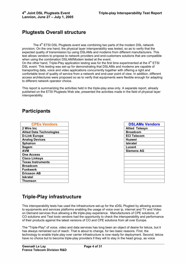
Plugtests Overall structure
The 4th ETSI DSL Plugtests event was combining two parts of the modem DSL network provision. On the one hand, the physical layer interoperability was tested, so as to verify that the expected quality of transmission by using DSLAMs and modems from different manufacturers. This test allows vendors to propose to network providers and end-customers solutions that are compatible when using the combination DSLAM/Modem tested at the event. On the other hand, Triple-Play application testing was for the first time experimented at the 4th ETSI DSL event. This testing was set-up for demonstrating that DSLAMs and modems are capable of transporting data, voice and video applications concurrently together with offering a right and confortable level of quality of service from a network and end-user point of view. In addition, different access architectures were proposed so as to verify that equipments were flexible enough for adapting to different network operator choice. This report is summarizing the activities held in the triple-play area only. A separate report, already published on the ETSI Plugtests Web site, presented the activities made in the field of physical layer interoperability.
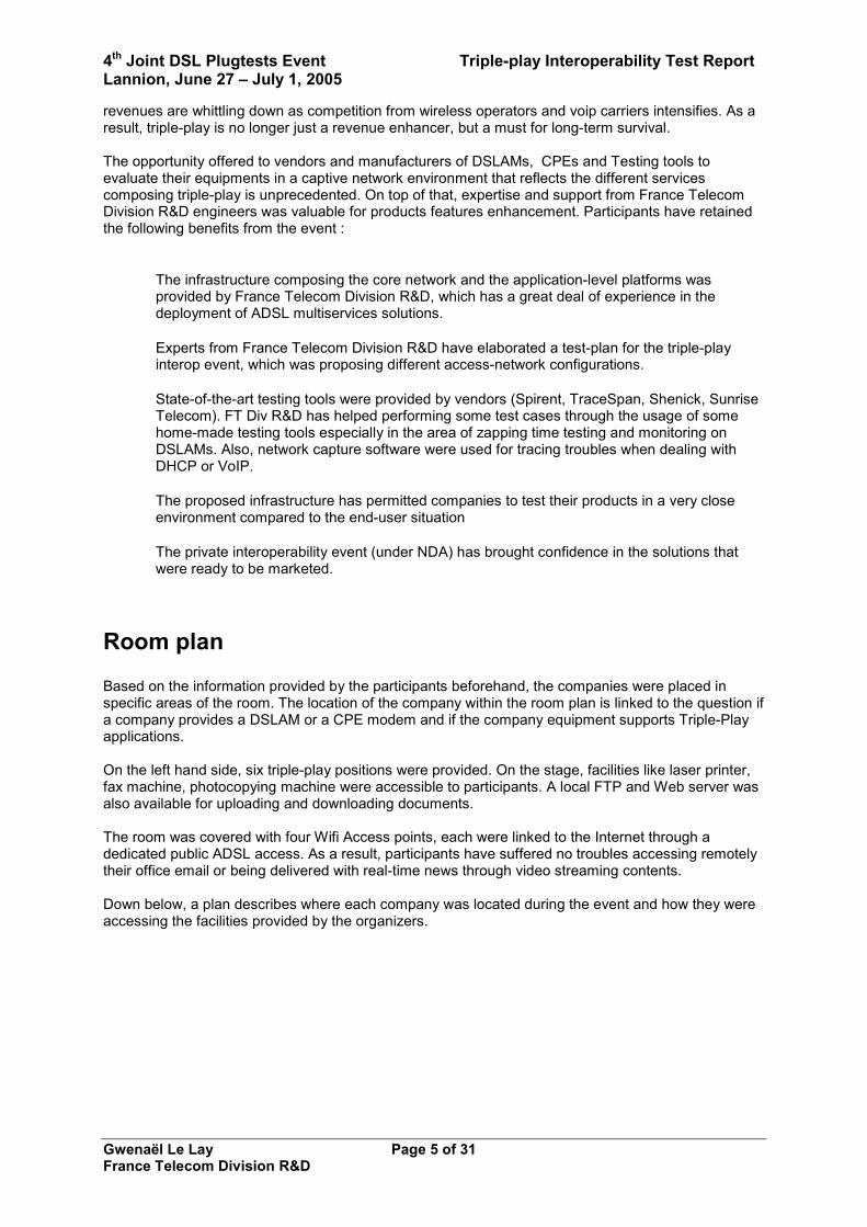
Participants
CPEs Vendors DSLAMs Vendors 2 Wire Inc Allied Telesyn Allied Data Technologies Broadcom D-Link Europe ECI Telecom Analog Devices Huawei Sphairon Iskratel Sagem Lucent AVM Siemens AG One Access Cisco Linksys Texas Instruments Broadcom Funkwerk Ericsson AB Iskratel Thomson
Triple-Play infrastructure This interoperability tests has used the infrastructure set-up for the xDSL Plugtest by allowing access to equipments and services platforms enabling the usage of voice over ip, internet and TV and Video on Demand services thus allowing a life triple-play experience. Manufacturers of CPE solutions, of CO solutions and Test tools vendors had the opportunity to check the interoperability and performance of their products against the latest versions of CO and CPE solutions from all over Europe. The "Triple-Play" of voice, video and data services has long been an object of desire for telcos, but it has always remained out of reach. That is about to change, for two basic reasons. First, the technology to enable triple play over carrier infrastructure is now ready for deployment. Second, telcos have no choice but to become triple-play providers if they will to stay in the head group, as voice
4th Joint DSL Plugtests Event Triple-play Interoperability Test Report Lannion, June 27 – July 1, 2005
Gwenaël Le Lay Page 5 of 31 France Telecom Division R&D
revenues are whittling down as competition from wireless operators and voip carriers intensifies. As a result, triple-play is no longer just a revenue enhancer, but a must for long-term survival. The opportunity offered to vendors and manufacturers of DSLAMs, CPEs and Testing tools to evaluate their equipments in a captive network environment that reflects the different services composing triple-play is unprecedented. On top of that, expertise and support from France Telecom Division R&D engineers was valuable for products features enhancement. Participants have retained the following benefits from the event :
• The infrastructure composing the core network and the application-level platforms was provided by France Telecom Division R&D, which has a great deal of experience in the deployment of ADSL multiservices solutions.
• Experts from France Telecom Division R&D have elaborated a test-plan for the triple-play
interop event, which was proposing different access-network configurations.
• State-of-the-art testing tools were provided by vendors (Spirent, TraceSpan, Shenick, Sunrise Telecom). FT Div R&D has helped performing some test cases through the usage of some home-made testing tools especially in the area of zapping time testing and monitoring on DSLAMs. Also, network capture software were used for tracing troubles when dealing with DHCP or VoIP.
• The proposed infrastructure has permitted companies to test their products in a very close
environment compared to the end-user situation
• The private interoperability event (under NDA) has brought confidence in the solutions that were ready to be marketed.
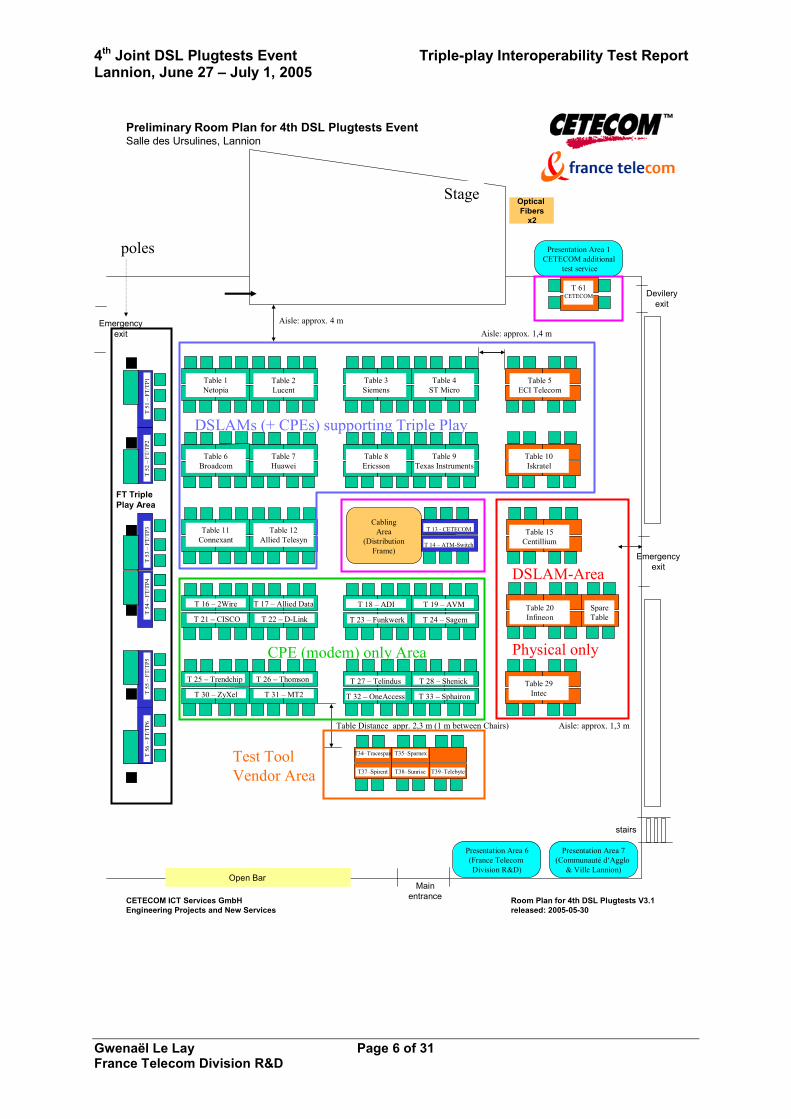
Room plan Based on the information provided by the participants beforehand, the companies were placed in specific areas of the room. The location of the company within the room plan is linked to the question if a company provides a DSLAM or a CPE modem and if the company equipment supports Triple-Play applications. On the left hand side, six triple-play positions were provided. On the stage, facilities like laser printer, fax machine, photocopying machine were accessible to participants. A local FTP and Web server was also available for uploading and downloading documents. The room was covered with four Wifi Access points, each were linked to the Internet through a dedicated public ADSL access. As a result, participants have suffered no troubles accessing remotely their office email or being delivered with real-time news through video streaming contents. Down below, a plan describes where each company was located during the event and how they were accessing the facilities provided by the organizers.
4th Joint DSL Plugtests Event Triple-play Interoperability Test Report Lannion, June 27 – July 1, 2005
Gwenaël Le Lay Page 6 of 31 France Telecom Division R&D
poles
Stage
CETECOM ICT Services GmbHEngineering Projects and New Services
Room Plan for 4th DSL Plugtests V3.1released: 2005-05-30
Preliminary Room Plan for 4th DSL Plugtests EventSalle des Ursulines, Lannion
stairs
Mainentrance
Open Bar
Emergencyexit
Devileryexit
Presentation Area 1CETECOM additional
test service
Presentation Area 7(Communauté d‘Agglo
& Ville Lannion)
CablingArea
(DistributionFrame)
FT TriplePlay Area
DSLAM-Area
DSLAMs (+ CPEs) supporting Triple Play
CPE (modem) only Area
Aisle: approx. 1,4 m
Table Distance appr. 2,3 m (1 m between Chairs)
Optical Fibers
x2
Aisle: approx. 4 m
Presentation Area 6(France Telecom Division R&D)
Aisle: approx. 1,3 m
Emergencyexit
Table 1Netopia
Table 2Lucent
Table 3Siemens
Table 4ST Micro
Table 6Broadcom
Table 7Huawei
Table 8Ericsson
Table 9Texas Instruments
Table 10Iskratel
Table 11Connexant
Table 12Allied Telesyn
Table 15Centillium
T 16 – 2Wire
T 21 – CISCO
T 17 – Allied Data
T 22 – D-LinkTable 20Infineon
Table 29Intec
T 18 – ADI
T 23 – Funkwerk
T 19 – AVM
T 24 – Sagem
T 25 – Trendchip
T 30 – ZyXel
T 26 – Thomson
T 31 – MT2
T 27 – Telindus T 28 – Shenick
T 33 – Sphairon
Physical only
Test ToolVendor Area
T 13 - CETECOM
T52
–FT
/TP2
T51
–FT
/TP1
T54
–FT
/TP4
T55
–FT
/TP5
T56
–FT
/TP6
T53
–FT
/TP3
Table 5ECI Telecom
T 14 – ATM-Switch
T38–SunriseT37–Spirent
T35–Sparnex
T 32 – OneAccess
T34–Tracespan
T39–Telebyte
SpareTable
T 61CETECOM
4th Joint DSL Plugtests Event Triple-play Interoperability Test Report Lannion, June 27 – July 1, 2005
Gwenaël Le Lay Page 7 of 31 France Telecom Division R&D
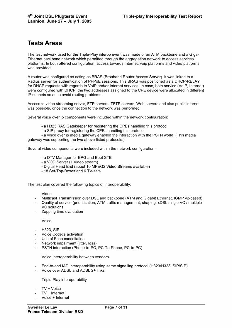
Tests Areas The test network used for the Triple-Play interop event was made of an ATM backbone and a Giga-Ethernet backbone network which permitted through the aggregation network to access services platforms. In both offered configuration, access towards Internet, voip platforms and video platforms was provided. A router was configured as acting as BRAS (Broaband Router Access Server). It was linked to a Radius server for authentication of PPPoE sessions. This BRAS was positioned as a DHCP-RELAY for DHCP requests with regards to VoIP and/or Internet services. In case, both service (VoIP, Internet) were configured with DHCP, the two addresses assigned to the CPE device were allocated in different IP subnets so as to avoid routing problems. Access to video streaming server, FTP servers, TFTP servers, Web servers and also public internet was possible, once the connection to the network was performed. Several voice over ip components were included within the network configuration:
- a H323 RAS Gatekeeper for registering the CPEs handling this protocol - a SIP proxy for registering the CPEs handling this protocol - a voice over ip media gateway enabled the interaction with the PSTN world. (This media
gateway was supporting the two above-listed protocols.) Several video components were included within the network configuration:
- a DTV Manager for EPG and Boot STB - a VOD Server (1 Video stream)
- Digital Head End (about 10 MPEG2 Video Streams available) - 18 Set-Top-Boxes and 6 TV-sets
The test plan covered the following topics of interoperability:
• Video - Multicast Transmission over DSL and backbone (ATM and Gigabit Ethernet, IGMP v2-based) - Quality of service (prioritization, ATM traffic management, shaping, xDSL single VC / multiple
VC solutions - Zapping time evaluation
• Voice
- H323, SIP - Voice Codecs activation - Use of Echo cancellation - Network impairment (jitter, loss) - PSTN interaction (Phone-to-PC, PC-To-Phone, PC-to-PC)
• Voice Interoperability between vendors - End-to-end IAD interoperability using same signalling protocol (H323/H323, SIP/SIP) - Voice over ADSL and ADSL 2+ links
• Triple-Play interoperability
- TV + Voice - TV + Internet - Voice + Internet
4th Joint DSL Plugtests Event Triple-play Interoperability Test Report Lannion, June 27 – July 1, 2005
Gwenaël Le Lay Page 8 of 31 France Telecom Division R&D
- TV + Voice + Internet
Undelying Test Bed
Eth/Usb
Z interface
Ethernet
Settop-box(TV + VoD)
CPE – 1 Triple-Play
Analog phone
Cabling AreaDistribut ion
Frame
Analog phone for access to public switched network
End-User PC
ATM Switch
Video BRAS
VOIP & Internet BRAS
Giga-EthernetSwitch
VOIP path
Internet path
Video path
STM1 -Link
STM1 -Link
1Gbs -Link
1Gbs -Link
Video Vlan
VOIP Vlan Internet Vlan
H323 RAS GK
SIP Proxy
IP Backbone
network
Voip Gateway
PSTN PSTN switchswitch
PRI -Link
Analog line
Video flow
VOIP flow
Digital TV head-end
VOD servers
Internet flow
Giga-Ethernet Collect network
ATM Collect network
Internet
xDSL Plug-Tests 2005
TRIPLE-PLAYTEST
ENVIRONMENT
DSLAMEth - A
DSLAMATM - 1
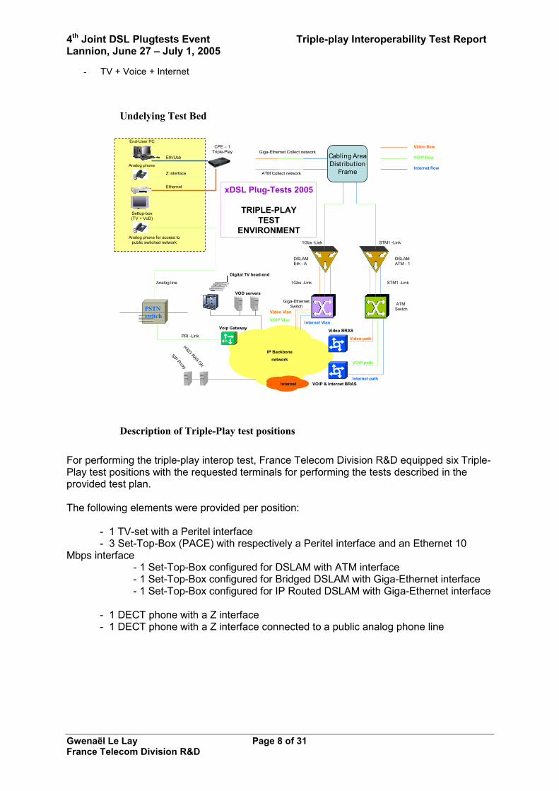
Description of Triple-Play test positions
For performing the triple-play interop test, France Telecom Division R&D equipped six Triple-Play test positions with the requested terminals for performing the tests described in the provided test plan. The following elements were provided per position:
- 1 TV-set with a Peritel interface - 3 Set-Top-Box (PACE) with respectively a Peritel interface and an Ethernet 10 Mbps interface - 1 Set-Top-Box configured for DSLAM with ATM interface - 1 Set-Top-Box configured for Bridged DSLAM with Giga-Ethernet interface - 1 Set-Top-Box configured for IP Routed DSLAM with Giga-Ethernet interface
- 1 DECT phone with a Z interface - 1 DECT phone with a Z interface connected to a public analog phone line
4th Joint DSL Plugtests Event Triple-play Interoperability Test Report Lannion, June 27 – July 1, 2005
Gwenaël Le Lay Page 9 of 31 France Telecom Division R&D
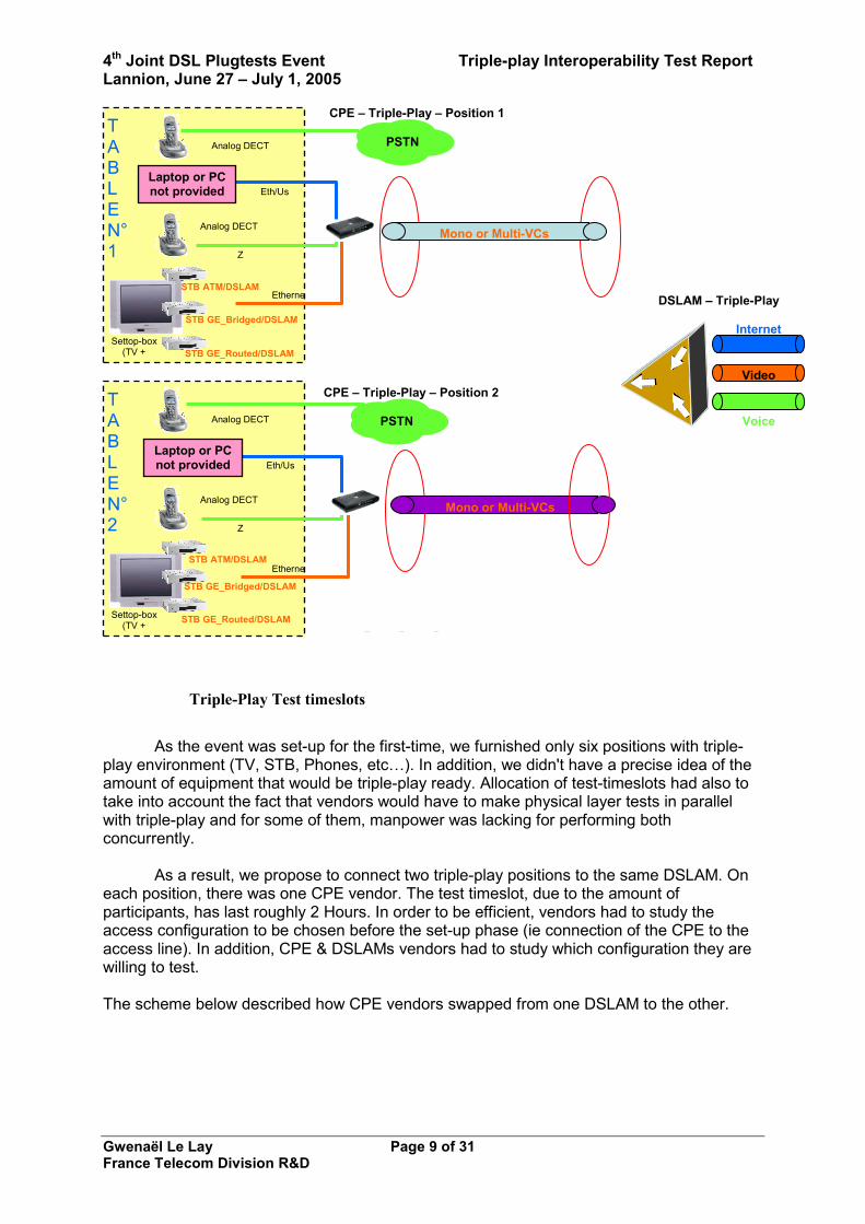
Triple-Play Test timeslots
As the event was set-up for the first-time, we furnished only six positions with triple-
play environment (TV, STB, Phones, etc…). In addition, we didn't have a precise idea of the amount of equipment that would be triple-play ready. Allocation of test-timeslots had also to take into account the fact that vendors would have to make physical layer tests in parallel with triple-play and for some of them, manpower was lacking for performing both concurrently.
As a result, we propose to connect two triple-play positions to the same DSLAM. On
each position, there was one CPE vendor. The test timeslot, due to the amount of participants, has last roughly 2 Hours. In order to be efficient, vendors had to study the access configuration to be chosen before the set-up phase (ie connection of the CPE to the access line). In addition, CPE & DSLAMs vendors had to study which configuration they are willing to test. The scheme below described how CPE vendors swapped from one DSLAM to the other.
End-User
DSLAM – Triple-Play
Eth/Us
Z
Settop-box (TV +
CPE – Triple-Play – Position 1
Analog DECT
Etherne
CPE – Triple-Play – Position 2
Analog DECT
End-User
Eth/Us
Z
Settop-box (TV +
Analog DECT
Etherne
Analog DECT
PSTN
PSTN
Mono or Multi-VCs
Mono or Multi-VCs
Internet
Video
Voice
STB ATM/DSLAM
STB GE_Bridged/DSLAM
STB GE_Routed/DSLAM
TABLEN°1
TABLEN°2
Laptop or PC not provided
Laptop or PC not provided
STB ATM/DSLAM
STB GE_Routed/DSLAM
STB GE_Bridged/DSLAM

4th Joint DSL Plugtests Event Triple-play Interoperability Test Report Lannion, June 27 – July 1, 2005
Gwenaël Le Lay Page 10 of 31 France Telecom Division R&D
A choice out of four access network configurations In order for the testing parties to agree on a target access network configuration, we proposed to choose through the following cases. The chosen configuration was then used for all the tests that were run during the timeslot that was allocated to the interop between a Triple-Play CPE and a DSLAM. Most of participants has taken the choice to try the four access network configurations in order to verify the flexibility of their equipments. This has made the test-timeslot a bit narrow as they were design initially for testing only one access network configuration. Based upon the number of participants the timeslot allocate for the interop testing between a CPE and DSLAM was limited to 2 Hours.
In addition, with regards to Video handling of the DSLAMs, it was important to note that two simultaneous multicast flows should be activated between the CPE and the DSLAM. If the DSLAM didn't allow this configuration, then the video service was not reachable. Four different access network configurations described hereafter were proposed which could be either used with DSLAM handling ATM interface or DSLAM handling Giga-Ethernet interface:
TABLE N°1 TABLE N°2 TABLE N°3 TABLE N°4 TABLE N°5 TABLE N°6
DSLAM N° A DSLAM N° B DSLAM N° C
CPE N°1
CPE N°2
CPE N°3
CPE N°4
CPE N°5
CPE N°6
CPE N°1
CPE N°2
CPE N°3
CPE N°4
CPE N°5
CPE N°1
CPE N°2
CPE N°3
CPE N°4
CPE N°5
CPE N°6
TS
1
TS
2
TS
3
CPE N°6

4th Joint DSL Plugtests Event Triple-play Interoperability Test Report Lannion, June 27 – July 1, 2005
Gwenaël Le Lay Page 11 of 31 France Telecom Division R&D
Eth/Usb
Z interface
Settop-box (TV + VoD)
CPE Triple-Play
Analog phone
End-User PC
Ethernet
DSLAM ATM or GE
Internet + VOIP – PPPoE – VPI/VCI : 8/35
Video – Bridged – VPI/VCI : 8/38
Internet – VPI/VCI : 8/35 – PPPoE – Up stream : 1 Mbits/sec - Down stream : xxx Mbits/sec – ATM Trafic
Video – VPI/VCI : 8/38 – Bridged – Up stream : 20 kbits/sec - Down stream : 4,6 Mbits/sec – ATM Trafic
Triple-Play – Access Network Configuration 1
Eth/Usb
Z interface
Settop-box (TV + VoD)
CPE Triple-Play
Analog phone
End-User PC
Ethernet
DSLAM ATM or GE
Internet – PPPoE – VPI/VCI : 8/35
Video – Bridged – VPI/VCI : 8/38
Internet – VPI/VCI : 8/35 – PPPoE – Up stream : 1 Mbits/sec - Down stream : xxx Mbits/sec – ATM Trafic
Video – VPI/VCI : 8/38 – Bridged – Up stream : 128 kbits/sec - Down stream : 4,6 Mbits/sec – ATM Trafic
Triple-Play Access Network Configuration 2
ToIP – VPI/VCI : 8/51 – Bridged – Up stream : 128 kbits/sec - Down stream : 128 Mbits/sec – ATM Trafic
ToIP – Bridged – VPI/VCI : 8/51
4th Joint DSL Plugtests Event Triple-play Interoperability Test Report Lannion, June 27 – July 1, 2005
Gwenaël Le Lay Page 12 of 31 France Telecom Division R&D
Eth/Usb
Z interface
Settop-box (TV + VoD)
CPE Triple-Play
Analog phone
End-User PC
Ethernet
DSLAM ATM or GE
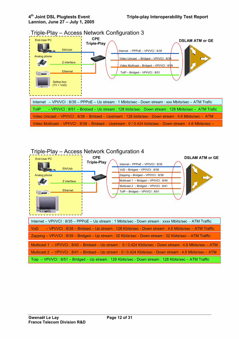
Internet – PPPoE – VPI/VCI : 8/35
Video Multicast – Bridged – VPI/VCI : 8/39
Internet – VPI/VCI : 8/35 – PPPoE – Up stream : 1 Mbits/sec - Down stream : xxx Mbits/sec – ATM Trafic
Video Multicast – VPI/VCI : 8/39 – Bridged – Upstream : 0 / 0.424 kbits/sec - Down stream : 4,6 Mbits/sec –
Triple-Play – Access Network Configuration 3
ToIP – VPI/VCI : 8/51 – Bridged – Up stream : 128 kbits/sec - Down stream : 128 Mbits/sec – ATM Trafic
ToIP – Bridged – VPI/VCI : 8/51
Video Unicast – Bridged – VPI/VCI : 8/38
Video Unicast – VPI/VCI : 8/38 – Bridged – Upstream : 128 kbits/sec - Down stream : 4,6 Mbits/sec – ATM
Eth/Usb
Z interface
Settop-box (TV + VoD)
CPE Triple-Play
Analog phone
End-User PC
Ethernet
DSLAM ATM or GE Internet – PPPoE – VPI/VCI : 8/35
VoD – Bridged – VPI/VCI : 8/38
Zapping – Bridged – VPI/VCI : 8/39
Multicast 1 – Bridged – VPI/VCI : 8/40
ToIP – Bridged – VPI/VCI : 8/51
Multicast 2 – Bridged – VPI/VCI : 8/41
Internet – VPI/VCI : 8/35 – PPPoE – Up stream : 1 Mbits/sec - Down stream : xxxx Mbits/sec - ATM Traffic
VoD – VPI/VCI : 8/38 – Bridged – Up stream : 128 Kbits/sec - Down stream : 4,6 Mbits/sec – ATM Traffic
Zapping – VPI/VCI : 8/39 – Bridged – Up stream : 32 Kbits/sec - Down stream : 32 Kbits/sec – ATM Traffic
Multicast 1 – VPI/VCI : 8/40 – Bridged – Up stream : 0 / 0,424 Kbits/sec - Down stream : 4,6 Mbits/sec – ATM
Multicast 2 – VPI/VCI : 8/41 – Bridged – Up stream : 0 / 0,424 Kbits/sec - Down stream : 4,6 Mbits/sec – ATM
Toip – VPI/VCI : 8/51 – Bridged – Up stream : 128 Kbits/sec - Down stream : 128 Kbits/sec – ATM Traffic
Triple-Play – Access Network Configuration 4

4th Joint DSL Plugtests Event Triple-play Interoperability Test Report Lannion, June 27 – July 1, 2005
Gwenaël Le Lay Page 13 of 31 France Telecom Division R&D
Test plan and associated results Test N° : 1 Ability of the CPE and DSLAM for handling a Triple-Play access network
configuration Test Purpose The aim of this test is to configure one of the 4 proposed access network
configurations on the triple-play CPE and on the DSLAM so as to carry different streams of traffic having different QoS needs.
Test Description Connect of the CPE WAN ADSL port to the DSLAM and then configure both equipments based on the chosen access network configuration. When the channels have been successfully set-up and activated, verify that the IP level configuration is OK and that the services platforms are reachable.
Test Set-up Connection of the CPE to the DSL access-line Configuration of the CPE logical channels based on the chosen configuration (VPI/VCI – ATM traffic class – ATM parameters) Configure the VCs so as to support unicast or multicast Connect the terminal devices to the CPE on the right Ethernet interface Switch the power on of the terminal devices Check that each devices is booting properly (Set-Top-Box, End-User-PC, etc..)
Diagram Please refer to the above mentioned diagrams
1. Triple-Play – Access Network Configuration 1 2. Triple-Play – Access Network Configuration 2 3. Triple-Play – Access Network Configuration 3 4. Triple-Play – Access Network Configuration 4
Expected result Each service plat-form is reachable from a logical point of view
Feedback from the tests performed
Most vendors succeeded in set-up these configurations. However, the main problems that have faced in the configuration of a separated and dedicated Virtual Channel for carrying out the VoIP/ToIP stream. In fact, in most CPEs design, VoIP is carried using the VC allocated to Internet using a PPPoE style connection. In the configurations proposed for the Triple-Play interop test, the connection is made through DHCP and the VoIP stream is separated from the Internet stream, which force the CPE to handle two different IP addresses and routes for both services. In addition, several troubles appeared when starting the configuration on DSLAMs due to some Ethernet speed negotiation. After two days, most vendors have succeeded in tuning their equipement for delivering all services. One DSLAM vendor was fully successfull with the three proposed mode ie ATM and Ethernet Bridged and Routed mode on the same equipment.

4th Joint DSL Plugtests Event Triple-play Interoperability Test Report Lannion, June 27 – July 1, 2005
Gwenaël Le Lay Page 14 of 31 France Telecom Division R&D
Test N° : 2 Activation of the Internet service on the CPE Test Purpose The aim of this test is to configure the CPE for delivering a confortable Internet
service. This service will be handled on the dedicated virtual channel. The test will aim at showing that web contents can be downloaded easily and that the complete bandwidth can be used as long as the other services are not up and running.
Test Description Configure the CPE or the End-user PC with right login and password so as to access the internet through the dedicated channel. Route on the CPE the Internet traffic flow towards the correct virtual channel. Access some web servers and FTP some files in order to evaluate the amount of bandwidth available.
Test Setup & Procedure
Choose if the connection model will use PPPoE, DHCP or PPPoA (ATM DSLAM) If PPP is choosen, assigned a login and password (they will be mentioned on a flyer placed on each triple-play position) Launch the connection dial-up utility either on the modem or on the end-user PC Check that connection set-up is proceeding Check that a dynamic IP address was assigned to the CPE or the end-user PC Check that a default gateway was assigned Try to ping and traceroute a local FTP server (addresses of FTP servers will be mentioned on the flyer) Try to download a file and verify the download throughput Try to access a web site
Diagram
Expected result The CPE permits a comfortable, efficient and reliable access to internet contents (web, FTP, etc…)
Summary of results from the tests performed by vendors
In this test, the basic tasks that a modem and a DSLAM should provide were tested. All triple-play positions access were provisioned using ADSL 2+. The connection time tear-up to the BRAS was very low and Radius authentication, together with IP address allocation and routing was efficient. Downloading large files [95 Mo] using FTP was also straightforward, and in most cases an average rate of 19 Mbps (downstream) was obtained. Video streaming (800 Kb/s MPEG stream) was also run concurrently with the FTP download. The end-user quality was still stable while performing all these services. In addition, switching on the Set-Top-Box for watching TV did affect the downloading time, but still all services were reachable in a comfortable manner.
Eth/Usb
Z interface
Settop-box (TV + VoD)
CPE Triple-Play
Analog phone
End-User PC
Ethernet
DSLAM ATM OR GE
Internet – PPPoE – VPI/VCI : 8/35
Triple-Play Test Case – Number 2
INTERNET VC
WE
Bserver
FTP
IP Backbonenetwork
Internet
ATM Switch
VOIP & Internet BRAS
Giga-Ethernet Switch
INTERNET VLAN

4th Joint DSL Plugtests Event Triple-play Interoperability Test Report Lannion, June 27 – July 1, 2005
Gwenaël Le Lay Page 15 of 31 France Telecom Division R&D
Test N° : 3 Activation of the Voice Over IP service on the CPE Test Purpose The aim of this test is to configure the CPE for delivering a voice over ip service.
This service can be handled through different kind of protocols. As a result, this test may be executed using three kinds of protocols which are H323, SIP.
Test Description Configure the CPE so as to activate the voip service. Route on the CPE the Voip traffic flow towards the correct virtual channel. Activate the chosen signaling protocol with the correct registration parameters. Perform a call toward a given analog line phone number. When a serie of call has been successful, perform a small number of test that will check that the voip conversation is not suffering QoS alteration. This test can be run using H323, SIP.
Test Setup & Procedure
Enter the voip configuration module on the CPE Choose between SIP and H323 as the signaling protocol to be used Assign a gatekeeper address, a H323-ID and a Phone number (H323) Assign a SIP proxy address, SIP Username using a phone-number, a domain name Assign some voice parameters (codecs, VAD, etc…) Set-up the ip channel for voip using either PPPoE/PPPoA or DHCP Verify that IP address was assigned to the connection either using DHCP or PPP Try to register your client to the gatekeeper or the SIP proxy Try to call the phone line available on the triple-Play position Evaluate subjectively the voice qos and the call setup time Maintain the call during at least two minutes Hang-up the call
Diagram
Expected result Calls can be established towards the PSTN analog line using one or all three above mentioned signaling protocols.
Eth/Usb
Z interface
Settop-box (TV + VoD)
CPE Triple-Play
Analog phone
End-User PC
Ethernet
DSLAM ATM OR GE
Internet + VOIP – PPPoE – VPI/VCI : 8/35
ToIP – Bridged – VPI/VCI : 8/51
Triple-Play Test Case – Number 3
INTERNET VC
H323
RA
SG
K
SIP
Proxy
IP Backbonenetwork
Voip Gateway PPSSTTNNsswwiittcchh PRI -Link
Analog line
Internet
ATM Switch
VOIP & Internet BRAS
Giga-Ethernet Switch
VOIP VLAN
OR
VOIP VC INTERNET VLAN
4th Joint DSL Plugtests Event Triple-play Interoperability Test Report Lannion, June 27 – July 1, 2005
Gwenaël Le Lay Page 16 of 31 France Telecom Division R&D
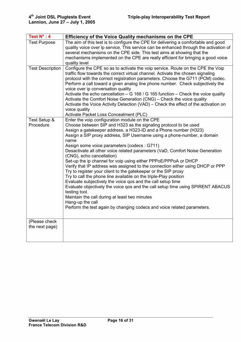
Test N° : 4 Efficiency of the Voice Quality mechanisms on the CPE Test Purpose The aim of this test is to configure the CPE for delivering a comfortable and good
quality voice over ip service. This service can be enhanced through the activation of several mechanisms on the CPE side. This test aims at showing that the mechanisms implemented on the CPE are really efficient for bringing a good voice quality level
Test Description Configure the CPE so as to activate the voip service. Route on the CPE the Voip traffic flow towards the correct virtual channel. Activate the chosen signaling protocol with the correct registration parameters. Choose the G711 (PCM) codec. Perform a call toward a given analog line phone number. Check subjectively the voice over ip conversation quality Activate the echo cancellation – G 168 / G 165 function – Check the voice quality Activate the Comfort Noise Generation (CNG) – Check the voice quality Activate the Voice Activity Detection (VAD) – Check the effect of the activation on voice quality Activate Packet Loss Concealment (PLC)
Test Setup & Procedure
Enter the voip configuration module on the CPE Choose between SIP and H323 as the signaling protocol to be used Assign a gatekeeper address, a H323-ID and a Phone number (H323) Assign a SIP proxy address, SIP Username using a phone-number, a domain name Assign some voice parameters (codecs : G711) Desactivate all other voice related parameters (VaD, Comfort Noise Generation (CNG), echo cancellation) Set-up the ip channel for voip using either PPPoE/PPPoA or DHCP Verify that IP address was assigned to the connection either using DHCP or PPP Try to register your client to the gatekeeper or the SIP proxy Try to call the phone line available on the triple-Play position Evaluate subjectively the voice qos and the call setup time Evaluate objectively the voice qos and the call setup time using SPIRENT ABACUS testing tool. Maintain the call during at least two minutes Hang-up the call Perform the test again by changing codecs and voice related parameters.
(Please check the next page)

4th Joint DSL Plugtests Event Triple-play Interoperability Test Report Lannion, June 27 – July 1, 2005
Gwenaël Le Lay Page 17 of 31 France Telecom Division R&D
Test N° : 4 (follow) Diagram
Expected result Activation of the Voice QoS mechanisms is resulting in an enhancement of the call quality. (objectively / subjectively)
Eth/Usb
Z interface
Settop-box (TV + VoD)
CPE Triple-Play
Analog phone
End-User PC
Ethernet
DSLAM ATM OR GE
Internet + VOIP – PPPoE – VPI/VCI : 8/35
ToIP – Bridged – VPI/VCI : 8/51
Triple-Play Test Case – Number 4
INTERNET VC
H323
RA
SG
K
SIP
Proxy
IP Backbonenetwork
Voip Gateway PPSSTTNNsswwiittcchh PRI -Link
Analog line
Internet
ATM Switch
VOIP & Internet BRAS
Giga-Ethernet Switch
VOIP VLAN
OR
VOIP VC INTERNET VLAN

4th Joint DSL Plugtests Event Triple-play Interoperability Test Report Lannion, June 27 – July 1, 2005
Gwenaël Le Lay Page 18 of 31 France Telecom Division R&D
Test N° : 5 Interoperability of two different vendors CPEs for Voice Over IP serviceTest Purpose The aim of this test is to configure the CPE for delivering a comfortable and good
quality voice over ip service when communicating with another CPE. This service can be enhanced through the activation of several mechanisms on each CPE side. This test aims at showing that the mechanisms implemented on both CPE are really efficient for bringing a good voice quality level and are interoperable.
Test Description Configure the CPE so as to activate the voip service. Route on the CPE the Voip traffic flow towards the correct virtual channel. Activate the chosen signaling protocol with the correct registration parameters. Choose the G711 (PCM) codec. Perform a call toward a given analog line phone number. Check subjectively the voice over ip conversation quality Activate the echo cancellation – G 168 / G 165 function – Check the voice quality Activate the Comfort Noise Generation (CNG) – Check the voice quality Activate the Voice Activity Detection (VAD) – Check the effect of the activation on voice quality Activate Packet Loss Concealment (PLC)
Test Setup & Procedure
Enter the voip configuration module on each CPE Choose between SIP and H323 as the signaling protocol to be used Assign a gatekeeper address, a H323-ID and a Phone number (H323) Assign a SIP proxy address, SIP Username using a phone-number, a domain name Assign some voice parameters (codecs : G711) Desactivate all other voice related parameters (VaD, Comfort Noise Generation (CNG), echo cancellation) Set-up the ip channel for voip using either PPPoE/PPPoA or DHCP Verify that IP address was assigned to the connection either using DHCP or PPP Try to register your client to the gatekeeper or the SIP proxy Try to call the phone line available on the triple-Play position Evaluate subjectively the voice qos and the call setup time Evaluate objectively the voice qos and the call setup time using SPIRENT ABACUS testing tool. Maintain the call during at least two minutes Hang-up the call Perform the test again by changing codecs and voice related parameters on both CPEs
(Please check the next page)

4th Joint DSL Plugtests Event Triple-play Interoperability Test Report Lannion, June 27 – July 1, 2005
Gwenaël Le Lay Page 19 of 31 France Telecom Division R&D
Diagram
Expected result Activation of the Voice QoS mechanisms is resulting in an enhancement of the call quality between the two CPE devices.
Voice Over IP tests results summary
The tests that were performed on voice over ip differ a lot between vendors. In fact, some CPEs were able to perform rapidely H323 and SIP signaling calls, and some others have suffered difficulties in registering with the H323 gatekeeper or the SIP Proxy. These troubles were due to different issues. Some CPEs implements very complex authentication mechanism that are based on H235 with a DNS address resolution which makes them looking after a specific gatekeeper. For this problem, the vendor had to reload a different firmware for getting registered. Some others had SIP stack that were not compatible with the SIP proxy proposed. As a result, they were able to set-up the signaling part of the call but were able to get the media stream. The call was then inefficient. This problem has appeared on several devices. Apart from that, the management of the dedicated VC for the VoIP flows was not straightforward for some CPE. In fact, in most case, the design of the CPE was based on the fact that the VoIP will reuse the data link for passing calls, and will register using the IP address allocated to the PPPoE session. As a result, the different access configurations proposed were not supported by some CPEs. Concerning Voice QoS measurements, the tests were performed with the help of Marc Horem from Spirent, who had brought an Abacus 5000 system, offering Ethernet and Z interface. Measurements were made on very few configurations as time and human resources for handling this part of the test plan was retricted. As a result, the following measurements are available. They have been performed with the same CPE but against two different DSLAMs. Some measurements were made with load conditions ie when all services were run concurrently. In that case, the CPU of the CPE has reached nearly 70% of constant usage.
Internet + VOIP – PPPoE – VPI/VCI : 8/35
VoIP – Bridged – VPI/VCI : 8/50
OR Eth/Usb
Z interface
CPE - Triple-Play
Analog phone
End-User PC
DSLAM ATM OR GE
Triple-Play Test Case – Number 4
INTERNET VC
H323
RA
SG
K
SIP
Proxy
IP Backbonenetwork
Voip GatewayPPSSTTNNsswwiittcchh PRI -Link
Analog line
Internet
ATM Switch
VOIP & Internet BRAS
Giga-Ethernet Switch
VOIP VLAN VOIP VCINTERNET VLAN
Internet + VOIP – PPPoE – VPI/VCI : 8/35
VoIP – Bridged – VPI/VCI : 8/50
OR
Eth/Usb
Z interface
Analog phone
End-User PC
CPE - Triple-Play

4th Joint DSL Plugtests Event Triple-play Interoperability Test Report Lannion, June 27 – July 1, 2005
Gwenaël Le Lay Page 20 of 31 France Telecom Division R&D
The graph below were obtained by performing a download of a 95 Mo file using FTP, while watching a movie on the laptop with a 800 Kb/s MPEG encoded stream and having a the VoD server which deliver a 7 Mbps stream on the Set-Top-Box
The graph below was obtained with different DSLAM compare to the above results. In that case, one performed a download of a 95 Mo file using FTP, while watching a movie on the laptop with a 800 Kb/s MPEG encoded stream and having a the VoD server which deliver a 7 Mbps stream on the Set-Top-Box
4th Joint DSL Plugtests Event Triple-play Interoperability Test Report Lannion, June 27 – July 1, 2005
Gwenaël Le Lay Page 21 of 31 France Telecom Division R&D
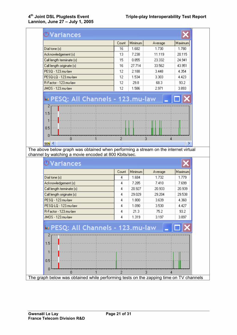
The above below graph was obtained when performing a stream on the internet virtual channel by watching a movie encoded at 800 Kbits/sec.
The graph below was obtained while performing tests on the zapping time on TV channels

4th Joint DSL Plugtests Event Triple-play Interoperability Test Report Lannion, June 27 – July 1, 2005
Gwenaël Le Lay Page 22 of 31 France Telecom Division R&D

4th Joint DSL Plugtests Event Triple-play Interoperability Test Report Lannion, June 27 – July 1, 2005
Gwenaël Le Lay Page 23 of 31 France Telecom Division R&D
Test N° : 6 Multicast test : Broadcast TV channels verification behind the CPE Test Purpose Using a FT Division R&D/RESA designed testing-tool, the goal of this test is to
verify that all channels are available and displayable on the TV screen.
Test Description The FT Division R&D/RESA tool is implemented on a PC running windows. The PC is connected to an Ethernet port on the CPE. A FT Division R&D/RESA person will perform the test so as to check that all channels are reachable.
Test Setup All Broadcast TV channels have to be configured on the DSLAM. The IGMP treatment has to be activated inside the DSLAM. The CPE has to support the correct PVC (configured on the DSLAM) to provide the Broadcast TV channel service.
Diagram DSLAM
Eth/Usb
Z interface
S ettop-box(TV + VoD)
CP E Triple-Play
Analog p hone
End-User PC
Ethernet ST M-1Or
ST M-4GE
IP Backbone
netw ork
VideoBRAS
Digital TV headendST M 1
Giga-Ethernet Swi tch
ATM Backbone
network
AT M Switch
VOD Server DTVManager
Ethernet
S T M 1
Mono/Multi VCs Video
FTR&D/RESATool
Expected result All channels have to be available and displayable
Test N° : 7 Unicast test : To verify that the Set-Top-Box is booting correctly
4th Joint DSL Plugtests Event Triple-play Interoperability Test Report Lannion, June 27 – July 1, 2005
Gwenaël Le Lay Page 24 of 31 France Telecom Division R&D
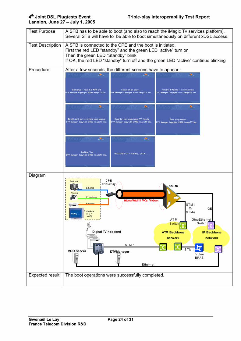
Test Purpose A STB has to be able to boot (and also to reach the iMagic Tv services platform). Several STB will have to be able to boot simultaneously on different xDSL access.
Test Description A STB is connected to the CPE and the boot is initiated. First the red LED “standby” and the green LED “active” turn on Then the green LED “Standby” blink If OK, the red LED “standby” turn off and the green LED “active” continue blinking
Procedure After a few seconds, the different screens have to appear :
Bienvenue - Pace 2.2 400 SP1DTV Manager Copyright 2000 imagicTV Inc.
Connexion en cours.....DTV Manager Copyright 2000 imagicTV Inc.
Numéro d'Abonné : xxxxxxxxxxDTV Manager Copyright 2000 imagicTV Inc.
En utilisant notre sys tème vous pourrezDTV Manager Copyright 2000 imagicTV Inc.
Regarder vos programmes TV favorisDTV Manager Copyright 2000 imagicTV Inc.
Bons programmesDTV Manager Copyright 2000 imagicTV Inc.
Caching FilesDTV Manager Copyright 2000 imagicTV Inc. WAITING FOT CHANNEL DATA......
Diagram
DSLAMEth/Usb
Z interface
S ettop-box(TV + VoD)
CP E Triple-Play
Analog p hone
End-User PC
Ethernet ST M-1Or
ST M-4GE
IP Backbone
netw ork
VideoBRAS
Digital TV headend
ST M 1
Giga-Ethernet Swi tch
ATM Backbone
network
AT M Switch
VOD Server DTVManager
Ethernet
S T M 1
Mono/Multi VCs Video
Booting....Booting.....
Expected result The boot operations were successfully completed.

4th Joint DSL Plugtests Event Triple-play Interoperability Test Report Lannion, June 27 – July 1, 2005
Gwenaël Le Lay Page 25 of 31 France Telecom Division R&D
Test N° : 8 After the STB boot, accessibility of the Electronic Program Guide (EPG)
Test Purpose After the STB boot, the EPG has to be accessible for the customer
Test Description A STB is connected to the CPE and the boot is ok. By using the iMagic Tv windows on the TV screen, the EPG has to be displayed. Afterwards, it has to be possible to select the Broadcast TV channels and to see the channel (without any default) on the TV screen.
Diagram DSLAM
Eth/Usb
Z interface
S ettop-box(TV + VoD)
CP E Triple-Play
Analog p hone
End-User PC
Ethernet ST M-1Or
ST M-4GE
IP Backbone
netw ork
VideoBRAS
Digital TV headend
ST M 1
Giga-Ethernet Swi tch
ATM Backbone
network
AT M Switch
VOD Server DTVManager
Ethernet
S T M 1
Mono/Multi VCs Video
Booting....
Expected result The EPG is accessible and this screen is displayed :

4th Joint DSL Plugtests Event Triple-play Interoperability Test Report Lannion, June 27 – July 1, 2005
Gwenaël Le Lay Page 26 of 31 France Telecom Division R&D
Test N° : 9 Zapping tests Test Purpose
After the STB boot and accessibility to the EPG, the customer has to be able to zap between the different broadcast Tv channels.
Test Description
First step, a STB is connected to the CPE and the boot and the EPG are ok . Zapping operations are performed. Second step, the zapping time has to be measured.
Procedure On the Remote Control : Click on “Home” to access to EPG Select “Native EPG”, then select a TV Channel Or Type 100 for TV Channel 1, 101 for TV Channel 2,….etc…. Use “Line +” or “Line –“ to change the TV Channel After these tests, call a person of FTR&D to use the Zapping tool.
Diagram DSLAM
Eth/Usb
Z interface
S ettop-box(TV + VoD)
CP E Triple-Play
Analog p hone
End-User PC
Ethernet ST M-1Or
ST M-4GE
IP Backbone
netw ork
VideoBRAS
ST M 1
Giga-Ethernet Swi tch
ATM Backbone
network
AT M Switch
VOD Server DTVManager
Ethernet
S T M 1
Mono/Multi VCs Video
FTR&D/RESATool
Digital TV headend
ZappingTests
Expected result
The zapping is working properly. The intrinsic zapping time of the DSLAM has to be less than 130 ms in stress conditions.
Summary of results from the tests performed by vendors
All results presented below were obtained using a FT Division R&D home-made zapping testing tool. This tool is plugged behind a DSL modem on the Ethernet port that is used fort he Set-Top-Box connectivity. Then, the tool operates a loop of the full set of TV channels that can be delivered. Then, it measures the network delay of a zapping request ie the time between the request to the service platform and the reception of the first packet of video. This measure gives an idea of the zapping request processing time of the network chain and the service platform. The some sample results are presented below. They were obtainned by using different combination of Modem vs DSLAM. Three graphs are shown :
- The first one shows a very regular mean zapping time of 30 ms - The second one is more unsteady and shows a mean zapping time of 45 ms

4th Joint DSL Plugtests Event Triple-play Interoperability Test Report Lannion, June 27 – July 1, 2005
Gwenaël Le Lay Page 27 of 31 France Telecom Division R&D
- The thrird one which is again regular shows a mean zapping time of 50 ms These measurements were made with load conditions ie the DSLAM was not stressed with a dedicated testing tool, and the modem was not running any heavy consuming applications.

4th Joint DSL Plugtests Event Triple-play Interoperability Test Report Lannion, June 27 – July 1, 2005
Gwenaël Le Lay Page 28 of 31 France Telecom Division R&D

4th Joint DSL Plugtests Event Triple-play Interoperability Test Report Lannion, June 27 – July 1, 2005
Gwenaël Le Lay Page 29 of 31 France Telecom Division R&D
Test N° : 10 VoD service activation Test Purpose A VoD has to be selected and to be displayed on the TV screen
Procedure On the Remote Control : Click on “Home” to access to EPG Select “Movies Manager”, then select a “Category” and then a “Movie”Click always on “Preview” to play the movie
Diagram DSLAM
Eth/Usb
Z interface
S ettop-box(TV + VoD)
CP E Triple-Play
Analog p hone
End-User PC
Ethernet ST M-1Or
ST M-4GE
IP Backbone
netw ork
VideoBRAS
Digital TV headend
ST M 1
Giga-Ethernet Swi tch
ATM Backbone
network
AT M Switch
VOD Server DTVManager
Ethernet
S T M 1
Mono/Multi VCs Video
VOD
Expected result The VoD service is working properly.

4th Joint DSL Plugtests Event Triple-play Interoperability Test Report Lannion, June 27 – July 1, 2005
Gwenaël Le Lay Page 30 of 31 France Telecom Division R&D
Test N° : 11 Availability of the Video services for all the xDSL ports on the DSLAM Test Purpose The goal is to verify if when the customer 1 asks for the channel B, this channel is
not sent on the others xDSL customers.
Test Description The customer 1 and 2 are watching respectively the channel A and B. The customer 1 asks for the channel C. Others use cases: - when the customer 1 asks for a VoD - when the customers 2 is watching VoD, the customer 1 asks for a different VoD.
Procedure You can do the tests N° 6 to 10
Diagram
DSLAM
Settop-box(TV + VoD)
CPE 1 Trip le-Play
Ethe rnet
ST M-1Or
ST M-4GE
IP Backbone
network
VideoBRAS
Digital TV headendST M 1
Giga-Ethern et Switch
ATM Backbone
network
AT M Swi tch
VOD Server DTVManager
Eth ernet
ST M 1
Mono/Multi VCs Video
Settop-box(TV + VoD)
CPE 2 Triple-Play
Ethernet
Expected result No side-effects are noticeable during the different use cases.

4th Joint DSL Plugtests Event Triple-play Interoperability Test Report Lannion, June 27 – July 1, 2005
Gwenaël Le Lay Page 31 of 31 France Telecom Division R&D
CONCLUSION This first Triple-Play interoperability and performance plugtests has offered to vendors of DSLAMs and CPEs to tune each other in almost real-life conditions. The services platforms accessible for performing the tests were flexible and open enough to interop with almost every vendors. Some who did experienced troubles have found mistakes in their firmware implementation and have also taken an opportunity to add features to their boxes. The event was successful on the organizers point of view. On technical side, things can be improved as this was the first try. In fact, we notice that we were lacking manpower on the assistance to vendors especially during the first two days were tuning of devices was operated. In addition, some advance testing tools in the area of voice quality measurements would be interesting together with some tools for saturating the access network with ip streams. In fact, most of the measurements performed were made with almost no load on the DSLAMs nor on the backbone network. We also notice that almost all vendors are able to deliver commercial triple-play products which mean that more triple-play positions should be provisioned in the future. The 4th DSL plugtests Event was a great success for all involved parties: the participants, the technology, the DSL industry in general, the standardization (ETSI), the organizers of the event (France Telecom and CETECOM ICT Services). The combination of physical layer interoperability testing and triple-Play application testing was a straightforward approach, which lead to a high number of participating companies ending up to an extremely busy and fruitful testing week.
The reader of this document is invited to also read the further information that is provided at http://www.etsi.org/plugtests/.