5 6 7 8 9 10 11 12 13 14 15 16 - aboveboardelectronics.com · example: convert a rotor inertia of...
TRANSCRIPT
[
I
R
1
2
3
4
5
6
7
8
9
10
11
12
13
T
14
15
1614-1
PHONE: 516.328.3300 • FAX: 516.326.8827 • WWW.SDP-SI.COM
0 1Inch
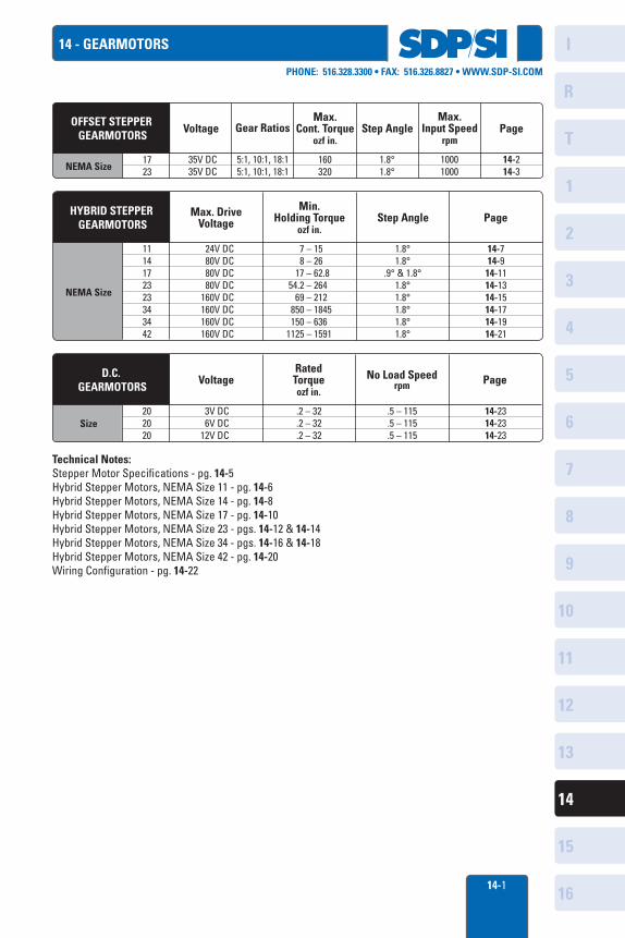
14 - GEARMOTORS
Voltage Gear RatiosMax.
Cont. Torqueozf in.
Step Angle
35V DC35V DC
1723
OFFSET STEPPER GEARMOTORS
5:1, 10:1, 18:15:1, 10:1, 18:1
160320
10001000
14-214-3
1.8°1.8°
Max.Input Speed
rpmPage
NEMA Size
Max. DriveVoltage
Min. Holding Torque
ozf in.Step Angle
24V DC80V DC80V DC80V DC
160V DC160V DC160V DC160V DC
1114172323343442
HYBRID STEPPER GEARMOTORS
7 – 15 8 – 26 17 – 62.8 54.2 – 264 69 – 212 850 – 1845 150 – 6361125 – 1591
14-714-914-1114-1314-1514-1714-1914-21
1.8°1.8°
.9° & 1.8°1.8°1.8°1.8°1.8°1.8°
Page
NEMA Size
VoltageRated Torqueozf in.
No Load Speedrpm Page
3V DC6V DC
12V DC
202020
D.C. GEARMOTORS
.2 – 32
.2 – 32
.2 – 32
.5 – 115
.5 – 115
.5 – 115
14-2314-2314-23
Size
Technical Notes:Stepper Motor Specifications - pg. 14-5Hybrid Stepper Motors, NEMA Size 11 - pg. 14-6Hybrid Stepper Motors, NEMA Size 14 - pg. 14-8Hybrid Stepper Motors, NEMA Size 17 - pg. 14-10Hybrid Stepper Motors, NEMA Size 23 - pgs. 14-12 & 14-14Hybrid Stepper Motors, NEMA Size 34 - pgs. 14-16 & 14-18Hybrid Stepper Motors, NEMA Size 42 - pg. 14-20Wiring Configuration - pg. 14-22
) ) )
SDPSI I
IIIIIIII1
,
I
R
1
2
3
4
5
6
7
8
9
10
11
12
13
T
14
15
1614-2
PHONE: 516.328.3300 • FAX: 516.326.8827 • WWW.SDP-SI.COM
0 1Inch
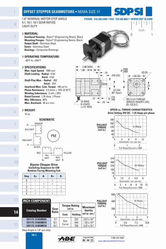
OFFSET STEPPER GEARMOTORS • NEMA SIZE 17
Gear Ratio
Torque Ratingozf in. Maximum
Inertiaozf in. sec.2Cont. Holding
5:110:118:1
SeeCurve
222444799
2.67 x 10⁻⁵
1.82 x 10⁻⁶
2.97 x 10⁻⁴
Catalog Number
INCH COMPONENT
S9117C-S18GM005S9117C-S18GM010S9117C-S18GM018
Step Angle is 1.8° per step.
2.86 MAX.
1.65 SQ.
1.88 .98.19
.470 (2X)
.12
.22 (2X)90° Apart
Ø .710 .708
Ø.2500 .2495
24 AWG8 LEADSL=12" MIN.
.79
.31
M3 X 0.5 THREAD(BRASS INSERT) (4X)Ø1.725 B.C.
Ø2.05
10:1Ratio
00
1.5 3 4.5 6
75150225300375
5:1Ratio
00 3 6
0 1 2
9 12
4080
120160180
PULLOUTTORQUE(ozf in.)
PULLOUTTORQUE(ozf in.)
PULLOUTTORQUE(ozf in.)
Gearmotor- rev. per sec.
Full Steps/Second x 1000
18:1Ratio
00
1 2 3
0 3.6 7.2 10.8
200
400
600
Gearmotor- rev. per sec.
Full Steps/Second x 1000
0 2 4 6Gearmotor- rev. per sec.
Full Steps/Second x 10008 10 12
SPEED vs. TORQUE CHARACTERISTICSDrive Setting 35V DC - 1.25 Amps per phase
SCHEMATIC
PM
YELLOW
ORANGE
BLK/WHT
ORG/WHT
YEL/WHT RED/
WHT
BLACK
A+
A-
B+ B-
RED
01234
+--++
B-
--++-
++--+
-++--
Bipolar Chopper DriveSwitching Sequence for CW
Rotation Facing Mounting End
Step A+ B+A-
1.8° NOMINAL MOTOR STEP ANGLE5:1, 10:1, 18:1 GEAR RATIOSLIGHT-DUTY
MATERIAL: Gearhead Housing - Ryton® (Engineering Resin), Black Mounting Flanges - Ryton® (Engineering Resin), Black Output Shaft - Stainless Steel Gears - Stainless Steel Bearings - Composite Bushings
OPERATING TEMPERATURE: -40°F to +255°F
SPECIFICATIONS:Max. Input Speed: 1000 rpmShaft Loading - Radial: 4 lbf Axial: 4 lbfShaft Play Max. - Radial: .002 Axial: .010Gearhead Max. Cont. Torque: 160 ozf in.Phase Resistance: 3.3 ohms ± 10% @ 25°CWinding Inductance: 3 mH ± 20%Rated Current: 1.25 Amp. / PhaseMin. Efficiency: 80%Max. Backlash: 45 arc min.
WEIGHT: 13 oz.
sops ■ I '' 111 'I
-.I-
f A
E.
,
•
I
R
1
2
3
4
5
6
7
8
9
10
11
12
13
T
14
15
1614-3
PHONE: 516.328.3300 • FAX: 516.326.8827 • WWW.SDP-SI.COM
0 1Inch
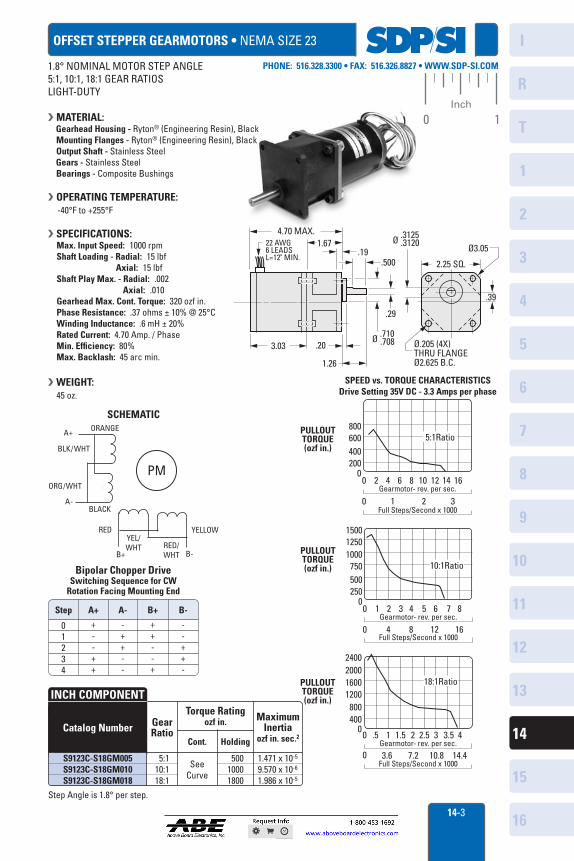
OFFSET STEPPER GEARMOTORS • NEMA SIZE 23
Gear Ratio
Torque Ratingozf in. Maximum
Inertiaozf in. sec.2Cont. Holding
5:110:118:1
SeeCurve
50010001800
1.471 x 10⁻⁵
9.570 x 10⁻⁶
1.986 x 10⁻⁵
Catalog Number
INCH COMPONENT
S9123C-S18GM005S9123C-S18GM010S9123C-S18GM018
Step Angle is 1.8° per step.
SCHEMATIC
PM
YELLOW
ORANGE
BLK/WHT
ORG/WHT
YEL/WHT RED/
WHT
BLACK
A+
A-
B+ B-
RED
01234
+--++
B-
--++-
++--+
-++--
Bipolar Chopper DriveSwitching Sequence for CW
Rotation Facing Mounting End
Step A+ B+A-
10:1Ratio
00
1 2 3 4 5 6 7 8
250500750
100012501500
5:1Ratio
00 2 4 6 8 10 12 14 16
0 1 2 3
200400600800
Gearmotor- rev. per sec.
Full Steps/Second x 1000
18:1Ratio
0
0 3.6 7.2 10.8 14.4
400800
1200160020002400
0 .5 1 1.5 2 2.5 3 3.5 4Gearmotor- rev. per sec.
Full Steps/Second x 1000
0 4Gearmotor- rev. per sec.
Full Steps/Second x 10008 1612
SPEED vs. TORQUE CHARACTERISTICSDrive Setting 35V DC - 3.3 Amps per phase
PULLOUTTORQUE(ozf in.)
PULLOUTTORQUE(ozf in.)
PULLOUTTORQUE(ozf in.)
4.70 MAX.
2.25 SQ.
1.67.19
.500
.29
.203.03
22 AWG6 LEADSL=12" MIN.
Ø .3125 .3120
1.26
.39
Ø.205 (4X)THRU FLANGEØ2.625 B.C.
Ø3.05
Ø .710 .708
1.8° NOMINAL MOTOR STEP ANGLE5:1, 10:1, 18:1 GEAR RATIOSLIGHT-DUTY
MATERIAL: Gearhead Housing - Ryton® (Engineering Resin), Black Mounting Flanges - Ryton® (Engineering Resin), Black Output Shaft - Stainless Steel Gears - Stainless Steel Bearings - Composite Bushings
OPERATING TEMPERATURE: -40°F to +255°F
SPECIFICATIONS:Max. Input Speed: 1000 rpmShaft Loading - Radial: 15 lbf Axial: 15 lbfShaft Play Max. - Radial: .002 Axial: .010Gearhead Max. Cont. Torque: 320 ozf in.Phase Resistance: .37 ohms ± 10% @ 25°CWinding Inductance: .6 mH ± 20%Rated Current: 4.70 Amp. / PhaseMin. Efficiency: 80%Max. Backlash: 45 arc min.
WEIGHT: 45 oz.
ME
sDPsi I 1 1111 '1
I
R
1
2
3
4
5
6
7
8
9
10
11
12
13
T
14
15
1614-4
PHONE: 516.328.3300 • FAX: 516.326.8827 • WWW.SDP-SI.COM
0 1Inch
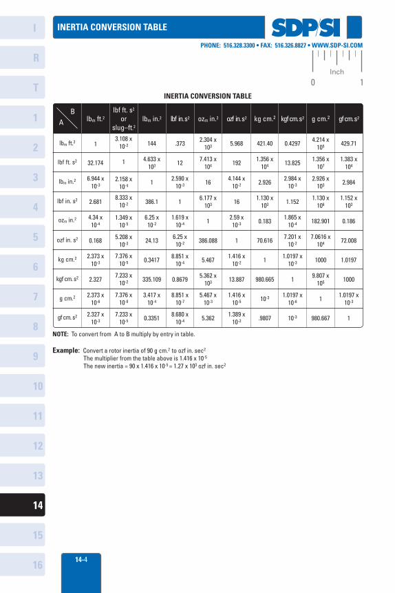
INERTIA CONVERSION TABLE
INERTIA CONVERSION TABLE
lbm ft.2 lbm in.2 lbf in. s2 ozm in.2 ozf in. s2
lbm ft.2
lbf ft. s2
lbm in.2
lbf in. s2
ozm in.2
ozf in. s2
kg cm.2
kgf cm. s2
g cm.2
gf cm. s2
AB
kg cm.2 kgf cm. s2 g cm.2 gf cm. s2
2.327 x10⁻³
3.108 x10⁻²
1
2.158 x10⁻⁴
8.333 x10⁻²
1.349 x10⁻⁵
5.208 x10⁻³
7.376 x10⁻⁵
7.233 x10⁻²
7.376 x10⁻⁸
7.233 x10⁻⁵ 0.3351 8.680 x
10-4
2.304 x10³
7.413 x10⁴
16
6.177 x10³
1
386.088
5.467
5.362 x10³
5.467 x10⁻³
5.362
5.968
192
4.144 x10⁻²
16
2.59 x10⁻³
1
1.416 x10⁻²
13.887
1.416 x10⁻⁵
1.389 x10⁻²
421.40
1.356 x10⁴
2.926
1.130 x10³
0.183
70.616
1
980.665
10-3
.9807
0.4297
13.825
2.984 x10⁻³
1.152
1.865 x10⁻⁴
7.201 x10⁻²
1.0197 x10⁻³
1
1.0197 x10⁻⁶
10-3
4.214 x10⁵
1.356 x10⁷
1.383 x10⁴
429.71
2.926 x10³
1.130 x10⁶
182.901
7.0616 x10⁴
1000
9.807 x10⁵
1
1980.667
2.984
1.152 x10³
0.186
72.008
1.0197
1000
1.0197 x10⁻³
NOTE: To convert from A to B multiply by entry in table.
Example: Convert a rotor inertia of 90 g cm.2 to ozf in. sec2
The multiplier from the table above is 1.416 x 10⁻⁵
The new inertia = 90 x 1.416 x 10-5 = 1.27 x 10³ ozf in. sec2
1
32.174
6.944 x10⁻³
2.681
4.34 x10⁻⁴
0.168
2.373 x10⁻³
2.327
2.373 x10⁻⁶
144
4.633 x10³
1
386.1
6.25 x10⁻²
24.13
0.3417
335.109
3.417 x10⁻⁴
.373
12
2.590 x10⁻³
1
1.619 x10⁻⁴
6.25 x10⁻²
8.851 x10⁻⁴
0.8679
8.851 x10⁻⁷
lbf ft. s2
orslug–ft.2

sops" IIIIIIII1
MENNEMMEN
I
R
1
2
3
4
5
6
7
8
9
10
11
12
13
T
14
15
1614-5
PHONE: 516.328.3300 • FAX: 516.326.8827 • WWW.SDP-SI.COM
0 1Inch
STEPPER MOTOR TECHNICAL SPECIFICATIONS
Mechanical, Electrical and Environmental Specifications
0.025(.001)
SIZE14
SIZE17
SIZEHT17
SIZE23
SIZEHT23
SIZE34
SIZE11
SIZEHT34
SIZE42
0.013(.0005)
0.013(.0005)
0.013(.0005)
0.025(.001)
0.051(.002)
0.051(.002)
0.051(.002)
0.051(.002)
0.051(.002)
0.076(.003)
0.076(.003)
0.076(.003)
0.076(.003)
0.076(.003)
0.076(.003)
0.076(.003)
0.076(.003)
0.051(.002)
0.051(.002)
0.051(.002)
0.051(.002)
0.051(.002)
0.076(.003)
0.051(.002)
0.076(.003)
0.076(.003)
-20°C to40°C
(-4°F to104°F)
-20°C to50°C
(-4°F to 122°F)
-20°C to50°C
(-4°F to 122°F)
-20°C to50°C
(-4°F to 122°F)
-20°C to50°C
(-4°F to 122°F)
-20°C to50°C
(-4°F to 122°F)
-20°C to50°C
(-4°F to 122°F)
-70°C to40°C
(-94°F to 104°F)
-10°C to40°C
(14°F to 104°F)
130°C (266°F)Class B
130°C (266°F)Class B
130°C (266°F)Class B
130°C (266°F)Class B
130°C (266°F)Class B
130°C (266°F)Class B
130°C (266°F)Class B
130°C (266°F)Class B
130°C (266°F)Class B
26 AWG 26 AWG 26 AWG 26 AWG 26 AWG 22 AWG 18 AWG 22 AWG —
4.89(1.1)
22.24(5)
22.24(5)
22.24(5)
66.72(15)
66.72(15)
111.21(25)
427.03(96)
111.21(25)
9.79(2.2)
13.34(3)
13.34(3)
13.34(3)
111.21(25)
111.21(25)
222.41(50)
800.68(180)
222.41(50)
0.01 max.@ 4.45 N
.0004 max.@ 1 lbf
0.025 max.@ 19.57 N
.001 max.@ 4.4 lbf
0.025 max.@ 22.24 N
.001 max.@ 5 lbf
0.025 max.@ 4.45 N
.001 max.@ 1 lbf
0.025 max.@ 4.45 N
.001 max.@ 1 lbf
0.02 max.@ 4.45 N
.0008 max.@ 1 lbf
0.025 max.@ 4.89 N
.001 max.@ 1.1 lbf( ) ( ) ( ) ( ) ( ) ( )
0.025 max.@ 4.89 N
.001 max.@ 1.1 lbf
0.025 max.@ 4.45 N
.001 max.@ 1 lbf ( ) ( ) ( )
( ) ( ) ( ) ( ) ( ) ( ) ( ) ( )
0.076 max.@ 9.79 N
.003 max.@ 2.2 lbf
0.076 max.@ 9.79 N
.003 max.@ 2.2 lbf
0.01 max.@ 8.9 N
.0004 max.@ 2 lbf
0.025 max.@ 29.36 N
.001 max.@ 6.6 lbf
0.076 max.@ 9.79 N
.003 max.@ 2.2 lbf
0.025 max.@ 40.03 N
.001 max.@ 9 lbf
0.025 max.@ 66.72 N
.001 max.@ 15 lbf
0.076 max.@ 9.79 N
.003 max.@ 2.2 lbf
0.025 max.@ 66.72 N
.001 max.@ 15 lbf( )
Shaft Run-Out mm (inches)
Radial Play mm / N (inch / lbf)
End Play mm / N (inch / lbf)
Perpendicularity mm (inches)
Concentricity mm (inches)
Operating Temperature Range
Insulation Class
Lead Wire Gauge
Max. Radial Load N (lbf)
Max. Thrust Load N (lbf)
DESIGN TIPS:• Series-connect lead wires for best torque at low speeds.• Center tap to end or parallel-connect lead wires for best torque at higher speeds.• Keep motor case temperature below 100°C. This can be achieved by lowering the motor current or limiting the duty cycle.• Allow sufficient time to accelerate load.• Size motor with 100% safety factor for required torque and speed.• Do not disassemble motors. A significant reduction in motor performance will result.• Do not machine shafts without consulting Sterling Instrument.• Do not disconnect motor from drive while in operation.• Do not use holding torque/detent torque of motor as fail-safe brake.
MOTOR INSTALLATION TIPS:• Mount the motor securely against a surface with good thermal conductivity such as aluminum.• Properly align the motor with the load using a flexible coupling.• Protect the motor shaft from excessive thrust, overhung and shock loads.
STANDARD DESIGN FEATURES
SDPSI ■
•
I I I
I
R
1
2
3
4
5
6
7
8
9
10
11
12
13
T
14
15
1614-6
PHONE: 516.328.3300 • FAX: 516.326.8827 • WWW.SDP-SI.COM
0 1Inch
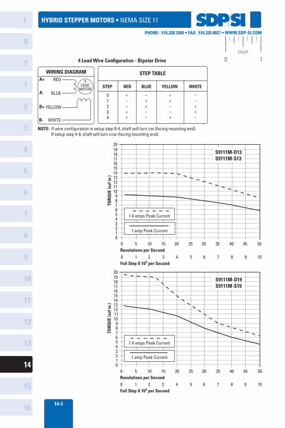
HYBRID STEPPER MOTORS • NEMA SIZE 11
2019181716151413121110
9876543210
0 5 10 15 20 25 30 35 40 45 50Revolutions per Second
S9111M-D13S9111M-S13
0 1 2 3 4 5 6 7 8 9 10Full Step X 103 per Second
TORQ
UE
(ozf
in.)
1 amp Peak Current
1.4 amps Peak Current
2019181716151413121110
9876543210
0 5 10 15 20 25 30 35 40 45 50Revolutions per Second
S9111M-D19S9111M-S19
0 1 2 3 4 5 6 7 8 9 10Full Step X 103 per Second
TORQ
UE
(ozf
in.)
1 amp Peak Current
1.4 amps Peak Current
STEP TABLE
STEP RED BLUE YELLOW WHITE
01234
+––++
–++––
++––+
––++–
WIRING DIAGRAMRED
BLUE
A+
A-
4LEAD
MOTOR
YELLOW
WHITE
B+
B-
4 Lead Wire Configuration - Bipolar Drive
NOTE: If wire configuration is setup step 0-4, shaft will turn cw (facing mounting end). If setup step 4-0, shaft will turn ccw (facing mounting end).
SCIPSII 1 1110 1
-0.--.1-
-I.-
1-
I
R
1
2
3
4
5
6
7
8
9
10
11
12
13
T
14
15
1614-7
PHONE: 516.328.3300 • FAX: 516.326.8827 • WWW.SDP-SI.COM
0 1Inch
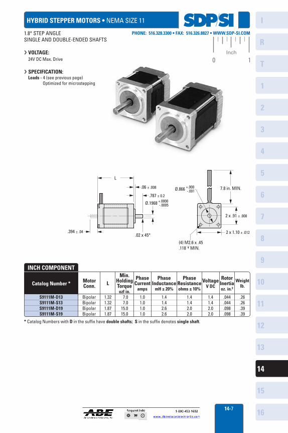
HYBRID STEPPER MOTORS • NEMA SIZE 11
(4) M2.6 x .45.118 MIN.
2 x 1.10 ± .012
2 x .91 ± .008
7.8 in. MIN.Ø.866 +.000 -.001
Ø.1968
.02 x 45°
.787 ± 0.2
.06 ± .008
L
.394 ± .04
+.0000 -.0005
MotorConn. L
Min.HoldingTorqueozf in.
Phase Current
amps
PhaseInductance
mH ± 20%
PhaseResistanceohms ± 10%
VoltageV DC
RotorInertiaoz. in.2
Weightlb.
BipolarBipolarBipolarBipolar
1.321.321.871.87
7.0 7.0
15.015.0
1.01.01.01.0
1.41.42.62.6
1.41.42.02.0
1.41.42.02.0
.044
.044
.098
.098
.26
.26
.39
.39
Catalog Number *
INCH COMPONENT
S9111M-D13S9111M-S13S9111M-D19S9111M-S19
* Catalog Numbers with D in the suffix have double shafts; S in the suffix denotes single shaft.
1.8° STEP ANGLESINGLE AND DOUBLE-ENDED SHAFTS
VOLTAGE:24V DC Max. Drive
SPECIFICATION: Leads - 4 (see previous page) Optimized for microstepping
SDPSI I
I IIIIIII I
1 1 1
1 1 1
N
I
R
1
2
3
4
5
6
7
8
9
10
11
12
13
T
14
15
1614-8
PHONE: 516.328.3300 • FAX: 516.326.8827 • WWW.SDP-SI.COM
0 1Inch
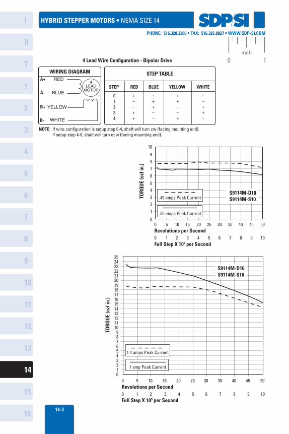
HYBRID STEPPER MOTORS • NEMA SIZE 14
10
9 8
7
6
5432
1
00 5 10 15 20 25 30 35 40 45 50Revolutions per Second0 1 2 3 4 5 6 7 8 9 10Full Step X 103 per Second
TORQ
UE
(ozf
in.)
.35 amps Peak Current
.49 amps Peak CurrentS9114M-D10S9114M-S10
202122232425
19181716151413121110
9876543210
0 5 10 15 20 25 30 35 40 45 50Revolutions per Second
S9114M-D16S9114M-S16
0 1 2 3 4 5 6 7 8 9 10Full Step X 103 per Second
TORQ
UE
(ozf
in.)
1 amp Peak Current
1.4 amps Peak Current
STEP TABLE
STEP RED BLUE YELLOW WHITE
01234
+––++
–++––
++––+
––++–
WIRING DIAGRAMRED
BLUE
A+
A-
4LEAD
MOTOR
YELLOW
WHITE
B+
B-
4 Lead Wire Configuration - Bipolar Drive
NOTE: If wire configuration is setup step 0-4, shaft will turn cw (facing mounting end). If setup step 4-0, shaft will turn ccw (facing mounting end).
,
SCIPM I
IIIIIIIII
I
R
1
2
3
4
5
6
7
8
9
10
11
12
13
T
14
15
16
0 1Inch
PHONE: 516.328.3300 • FAX: 516.326.8827 • WWW.SDP-SI.COM
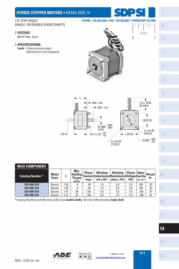
HYBRID STEPPER MOTORS • NEMA SIZE 14
MotorConn. L
Min.HoldingTorqueozf in.
Phase Current
amps
WindingInductance
mH ± 20%
WindingResistanceohms ± 10%
PhaseVoltage
VDC
RotorInertiaoz. in.2
Weightlb.
BipolarBipolarBipolarBipolar
1.001.001.571.57
88
2626
.35
.351.001.00
7.57.55.55.5
8.38.34.34.3
3.03.04.34.3
.051
.051
.109
.109
.33
.33
.47
.47
Catalog Number *
INCH COMPONENT
S9114M-D10S9114M-S10S9114M-D16S9114M-S16
* Catalog Numbers with D in the suffix have double shafts; S in the suffix denotes single shaft.
12 in. MIN.26 AWG
1.024 SQ.
1.38 SQ.
2 x #4-40STUDS
2 x #4-40HOLES2 x .25.39
L
.059 ± .004
.559 ± .019
Ø.1968(TYP)
+.0000 -.0004
+.00 -.03
Ø.866 +.000 -.001
1.8° STEP ANGLESINGLE- OR DOUBLE-ENDED SHAFTS
VOLTAGE: 80VDC Max. Drive
SPECIFICATIONS: Leads - 4 (see previous page) Optimized for microstepping
14-9
REV: 0703.12 mh
SDPSI I
I IIIIIII I 1 1 1
.......,
1 1 1 —..
--, ,., s.,
1 1 1
—.. N
N N
I
R
1
2
3
4
5
6
7
8
9
10
11
12
13
T
14
15
1614-10
PHONE: 516.328.3300 • FAX: 516.326.8827 • WWW.SDP-SI.COM
0 1Inch
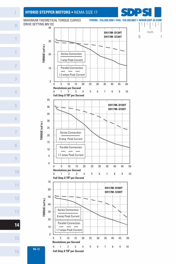
HYBRID STEPPER MOTORS • NEMA SIZE 17
40
00 5 10 15 20 25 30 35 40 45 50
TORQ
UE
(ozf
in.)
30
20
10
S9117M–D13HTS9117M–S13HT
Series Connection
.7 amp Peak Current
Parallel Connection
1.3 amps Peak Current
Revolutions per Second0 1 2 3 4 5 6 7 8 9 10Full Step X 103 per Second
Full Step X 103 per Second
0 5 10 15 20 25 30 35 40 45 50
TORQ
UE
(ozf
in.)
35
30
25
20
15
10
5
0
40
45
S9117M–D15HTS9117M–S15HT
Series Connection
.8 amp Peak Current
Parallel Connection
1.7 amps Peak Current
Revolutions per Second0 1 2 3 4 5 6 7 8 9 10
70
60
50
40
30
20
10
00 5 10 15 20 25 30 35 40 45 50
TORQ
UE
(ozf
in.)
Revolutions per Second
S9117M–D18HTS9117M–S18HT
Series Connection
.8 amp Peak Current
Parallel Connection
1.7 amps Peak Current
0 1 2 3 4 5 6 7 8 9 10
Full Step X 103 per Second
MAXIMUM THEORETICAL TORQUE CURVESDRIVE SETTING 80V DC

sops ■
I -I.. -.1-
-1.- -.1- -M.- .11-
i 4 4
-.11-
I
R
1
2
3
4
5
6
7
8
9
10
11
12
13
T
14
15
1614-11
PHONE: 516.328.3300 • FAX: 516.326.8827 • WWW.SDP-SI.COM
0 1Inch
HYBRID STEPPER MOTORS • NEMA SIZE 17
MotorConn. L
Min.HoldingTorqueozf in.
Phase Currentamps
StepAngle
PhaseInductancemH ± 20%
PhaseResistanceohms ± 10%
VoltageV DC
RotorInertiaoz. in.2
Weightlb.
Parallel
SeriesParallelUnipolarSeries
ParallelUnipolarSeries
ParallelUnipolar
1.54
1.301.301.301.541.541.541.851.851.85
17.0
31.431.422.251.051.036.162.862.844.4
.9
1.81.81.81.81.81.81.81.81.8
1.40
.671.34
.95
.851.701.20
.851.701.20
4.6
11.2 2.8 2.814.4 3.6 3.612.0 3.0 3.0
2.4
8.42.14.26.61.73.36.61.73.3
3.4
5.72.84.05.72.84.05.72.84.0
.13
.19
.19
.19
.29
.29
.29
.37
.37
.37
.55
.44
.44
.44
.57
.57
.57
.73
.73
.73
Catalog Number *
INCH COMPONENT
S9117MMS15
S9117M-D13HTS9117M-S13HT
S9117M-D15HTS9117M-S15HT
S9117M-D18HTS9117M-S18HT
* Catalog Numbers with D in the suffix have double shafts; S in the suffix denotes single shaft. Fig. 1 only available with a single shaft.
Fig. 1
Fig. 2
12 in. MIN.
4 x #4 - 40.17 DEEP
MOUNTING END
1.65 SQ.
Ø.866+.000 -.001
1.220 SQ.
.59L
.080
.59 ± .01
Ø.1968+.0000 -.0004
.177 ± .006 FLAT
FLAT.177 ± .006
.79 ± .02
1.22Ø.866Ø.1968
1.54 .94
4 x #4-40 .17 DEEP
Fig. 1
1.65 SQ.
Fig. 2
(TYP)
1
14
28
5 10
Torque(ozf in.)
Full-StepCurrent 0.8A/PhaseSupply Voltage 24V DC
Full Step per Sec x 1000
S9117MMS15
.9° & 1.8° STEP ANGLESSINGLE- OR DOUBLE-ENDED SHAFTS
VOLTAGE: 80V DC Max. Drive
SPECIFICATION: Leads - 8 (see wiring diagram page) Catalog Number S9117MMS15 is a 4 lead motor. Optimized for microstepping

SDPSCI
I III I III 1 ..........
..........
......._
I
R
1
2
3
4
5
6
7
8
9
10
11
12
13
T
14
15
1614-12
PHONE: 516.328.3300 • FAX: 516.326.8827 • WWW.SDP-SI.COM
0 1Inch
150
00 5 10 15 20 25 30 35 40 45 50Revolutions per Second0 1 2 3 4 5 6 7 8 9 10Full Step X 103 per Second
140130120110100
908070605040302010
TORQ
UE
(ozf
in.)
S9123M–S21HTS9123M–D21HT
Series Connection 1.4 amps Peak Current
Parallel Connection2.8 amps Peak Current
HYBRID STEPPER MOTORS • NEMA SIZE 23
0 5 10 15 20 25 30 35 40 45 50Revolutions per Second0 1 2 3 4 5 6 7 8 9 10Full Step X 103 per Second
TORQ
UE
(ozf
in.)
120110100908070605040302010 0
220210200190
230
180170160150140130
S9123M–S30HTS9123M–D30HT
Parallel Connection
1.4 amps Peak Current
Series Connection .7 amp Peak Current
225
250
25
0
0 5 10 15 20 25 30 35 40 45 50Revolutions per Second0 1 2 3 4 5 6 7 8 9 10Full Step X 103 per Second
175
150
125
75
50
TORQ
UE
(ozf
in.)
200
100Series Connection
2.1 amps Peak Current
Parallel Connection4.2 amps Peak Current
S9123M–S30HTAS9123M–D30HTA
MAXIMUM THEORETICAL TORQUE CURVESDRIVE SETTING 80V DC
- H -
.10
I I I
I
R
1
2
3
4
5
6
7
8
9
10
11
12
13
T
14
15
1614-13
PHONE: 516.328.3300 • FAX: 516.326.8827 • WWW.SDP-SI.COM
0 1Inch
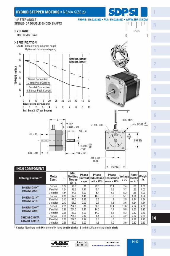
HYBRID STEPPER MOTORS • NEMA SIZE 23
MotorConn. L
Min.HoldingTorqueozf in.
Phase Current
amps
PhaseInductance
mH ± 20%
PhaseResistanceohms ± 10%
VoltageV DC
RotorInertiaoz. in.2
Weightlb.
SeriesParallelUnipolarSeries
ParallelUnipolarSeries
ParallelUnipolarSeries
ParallelUnipolar
1.541.541.542.132.132.132.992.992.992.992.992.99
76.676.654.2
177.0177.0125.0264.0264.0187.0264.0264.0187.0
.711.411.001.412.832.00.71
1.411.002.124.243.00
21.65.45.4
10.02.52.5
56.014.014.0
6.41.61.6
10.42.65.23.6
.91.8
16.44.18.22.0
.51.0
7.43.75.25.12.53.6
11.65.88.24.22.13.0
.66
.66
.661.641.641.642.622.622.622.622.622.62
1.001.001.001.541.541.542.202.202.202.202.202.20
Catalog Number *
INCH COMPONENT
S9123M-D15HTS9123M-S15HT
S9123M-D21HTS9123M-S21HT
S9123M-D30HTS9123M-S30HT
S9123M-D30HTAS9123M-S30HTA
* Catalog Numbers with D in the suffix have double shafts; S in the suffix denotes single shaft.
MOUNTINGEND
L.197.063 ± .008
.59 ± .01
Ø.250(TYP)
+.000 -.001
.787 ± .020.630 ± .039
.59 ± .01
18 in. MIN.
4 x Ø.205Ø1.50 ± .001
.9281.856 SQ.
.228 ± .006 FLAT
2.22 SQ.
+.01 -.00
0 5 10 15 20 25 30 35 40 45 50Revolutions per Second0 1 2 3 4 5 6 7 8 9 10Full Step X 103 per Second
Parallel Connection1.4 amps Peak Current
S9123M–S15HTS9123M–D15HT
Series Connection .7 amp Peak Current
70
60
0
50
40
30
20
10
TORQ
UE
(ozf
in.)
1.8° STEP ANGLESINGLE- OR DOUBLE-ENDED SHAFTS
VOLTAGE: 80V DC Max. Drive
SPECIFICATION: Leads - 8 (see wiring diagram page) Optimized for microstepping
SDPSI I
I IIIIIII I
--......
-.......
1 1 1
I
R
1
2
3
4
5
6
7
8
9
10
11
12
13
T
14
15
1614-14
PHONE: 516.328.3300 • FAX: 516.326.8827 • WWW.SDP-SI.COM
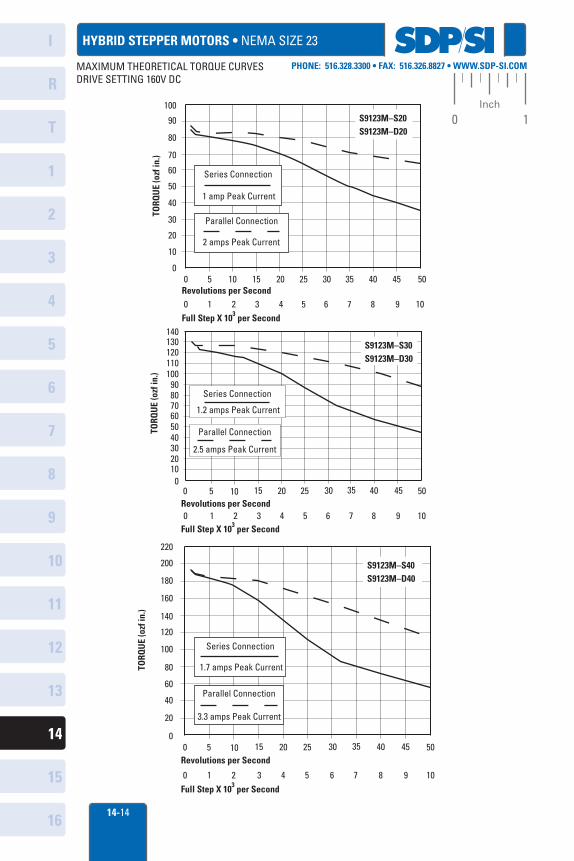
0 1Inch100
90
80
70
60
50
40
30
20
10
0 0 5 10 15 20 25 30 35 40 45 50
0 1 2 3 4 5 6 7 8 9 10
TORQ
UE
(ozf
in.)
Revolutions per Second
Full Step X 103 per Second
S9123M–S20S9123M–D20
Series Connection
1 amp Peak Current
Parallel Connection
2 amps Peak Current
140
908070605040302010
0 0 5 10 15 20 25 30 35 40 45 50
TORQ
UE
(ozf
in.)
Revolutions per Second
Full Step X 103 per Second
100110120130 S9123M–S30
S9123M–D30
Parallel Connection
2.5 amps Peak Current
Series Connection
1.2 amps Peak Current
0 1 2 3 4 5 6 7 8 9 10
200
180
160
140
120
100
80
60
40
20
0 0 5 10 15 20 25 30 35 40 45 50
TORQ
UE
(ozf
in.)
Revolutions per Second
0 1 2 3 4 5 6 7 8 9 10Full Step X 103 per Second
220
S9123M–S40S9123M–D40
Series Connection
1.7 amps Peak Current
Parallel Connection
3.3 amps Peak Current
HYBRID STEPPER MOTORS • NEMA SIZE 23
MAXIMUM THEORETICAL TORQUE CURVESDRIVE SETTING 160V DC
sops
1
I
R
1
2
3
4
5
6
7
8
9
10
11
12
13
T
14
15
1614-15
0 1Inch
Phone: 516.328.3300 • Fax: 516.326.8827 • www.sdP-si.com
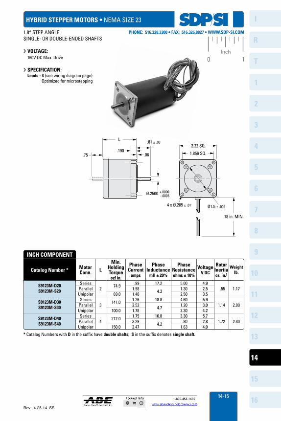
hybrid stePPer motors • nema size 23
motorconn. L
min.holdingtorqueozf in.
Phase current
amps
Phaseinductance
mH ± 20%
Phaseresistanceohms ± 10%
VoltageV dc
rotorinertiaoz. in.2
weightlb.
seriesParallelUnipolarseries
ParallelUnipolarseries
ParallelUnipolar
2
3
4
74.9
69.0
141.0
100.0
212.0
150.0
.991.981.401.262.521.781.753.292.47
17.2 4.3
18.8
4.7
16.8 4.2
5.001.302.504.601.202.303.30 .801.63
4.92.53.55.93.04.25.72.84.0
.55
1.14
1.72
1.17
2.00
2.80
catalog number *
inch comPonent
s9123m-d20s9123m-s20
s9123m-d30s9123m-s30
s9123m-d40s9123m-s40
* Catalog numbers with d in the suffix have double shafts; s in the suffix denotes single shaft.
2.22 SQ.L
.06
Ø.2500
4 x Ø.205 ± .01
+.0000 -.0005
.81 ± .03
1.856 SQ..75
18 in. MIN.
Ø1.5 ± .002
.190
1.8° sTeP anGLesinGLe- OR DOUBLe-enDeD sHaFTs
VoLtaGe: 160V DC max. Drive
sPeciFication: Leads - 8 (see wiring diagram page) Optimized for microstepping
Rev: 4-25-14 SS
SDPSI ■ I
R
1
2
3
4
5
6
7
8
9
10
11
12
13
T
14
15
1614-16
PHONE: 516.328.3300 • FAX: 516.326.8827 • WWW.SDP-SI.COM
0 1Inch
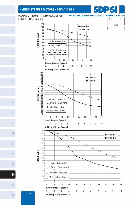
HYBRID STEPPER MOTORS • NEMA SIZE 34
200220
180
20
0 5 10 15 20 25 30 35 40 45 50Revolutions per Second0 1 2 3 4 5 6 7 8 9 10
Full Step X 103 per Second
Series Connection
2.4 amps Peak Current
Parallel Connection
4.8 amps Peak Current
140120100
6040
TORQ
UE
(ozf
in.) 160
80
0
S9134M–S25 S9134M–D25
0 5 10 15 20 25 30 35 40 45 50Revolutions per Second0 1 2 3 4 5 6 7 8 9 10
Full Step X 103 per Second
S9134M–S51 S9134M–D51
TORQ
UE
(ozf
in.)
500
450
375
300275250225200175150125100
755025 0
Series Connection
4.2 amps Peak Current
Parallel Connection
8.3 amps Peak Current
325
475
400425
350
0 5 10 15 20 25 30 35 40 45 50
Revolutions per Second
0 1 2 3 4 5 6 7 8 9 10
Full Step X 103 per Second
TORQ
UE
(ozf
in.)
425
375
300325
275250225200175150125100
755025 0
Series Connection
3.2 amps Peak Current
Parallel Connection
7 amps Peak Current
475
525
S9134M–S37 S9134M–D37
500
450
400
350
MAXIMUM THEORETICAL TORQUE CURVESDRIVE SETTING 160V DC
SOPS" IIIIIII1
I
R
1
2
3
4
5
6
7
8
9
10
11
12
13
T
14
15
1614-17
PHONE: 516.328.3300 • FAX: 516.326.8827 • WWW.SDP-SI.COM
0 1Inch
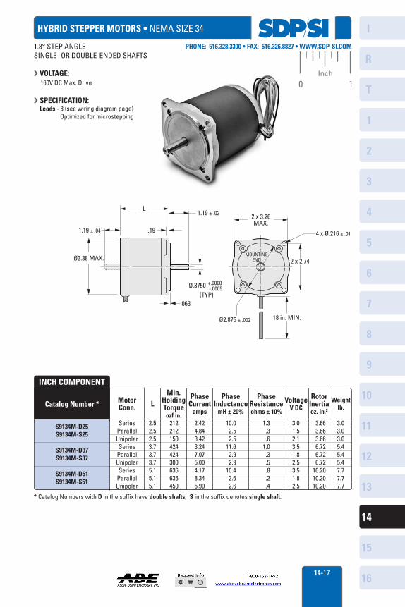
HYBRID STEPPER MOTORS • NEMA SIZE 34
MotorConn. L
Min.HoldingTorqueozf in.
Phase Current
amps
PhaseInductance
mH ± 20%
PhaseResistanceohms ± 10%
VoltageV DC
RotorInertiaoz. in.2
Weightlb.
SeriesParallelUnipolarSeries
ParallelUnipolarSeries
ParallelUnipolar
2.52.52.53.73.73.75.15.15.1
212212150424424300636636450
2.424.843.423.247.075.004.178.345.90
10.02.52.5
11.62.92.9
10.42.62.6
1.3.3.6
1.0.3.5.8.2.4
3.01.52.13.51.82.53.51.82.5
3.66 3.66 3.66 6.72 6.72 6.7210.2010.2010.20
3.03.03.05.45.45.47.77.77.7
Catalog Number *
INCH COMPONENT
S9134M-D25S9134M-S25
S9134M-D37S9134M-S37
S9134M-D51S9134M-S51
* Catalog Numbers with D in the suffix have double shafts; S in the suffix denotes single shaft.
L
.19
2 x 2.74
1.19 ± .04
Ø3.38 MAX.
.063
Ø2.875 ± .002
Ø.3750 +.0000 -.0005
1.19 ± .03 2 x 3.26MAX.
4 x Ø.216 ± .01
18 in. MIN.
MOUNTINGEND
(TYP)
1.8° STEP ANGLESINGLE- OR DOUBLE-ENDED SHAFTS
VOLTAGE: 160V DC Max. Drive
SPECIFICATION: Leads - 8 (see wiring diagram page) Optimized for microstepping
SDPSI I
I III I III I
-__ N
N
-....... 1 1 1
N N
I
R
1
2
3
4
5
6
7
8
9
10
11
12
13
T
14
15
1614-18
PHONE: 516.328.3300 • FAX: 516.326.8827 • WWW.SDP-SI.COM
0 1Inch
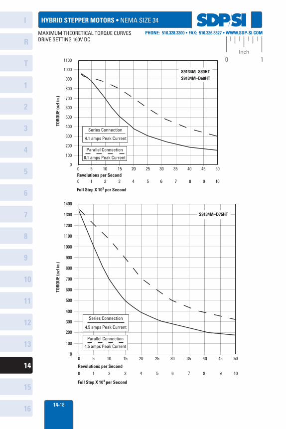
HYBRID STEPPER MOTORS • NEMA SIZE 34
1000
1100
900
100
0 5 10 15 20 25 30 35 40 45 50Revolutions per Second0 1 2 3 4 5 6 7 8 9 10
Full Step X 103 per Second
Series Connection
4.1 amps Peak Current
Parallel Connection
8.1 amps Peak Current
700
600
500
300
200
TORQ
UE
(ozf
in.)
800
400
0
S9134M–S60HTS9134M–D60HT
1000
1100
1200
1300
1400
900
100
0 5 10 15 20 25 30 35 40 45 50
Revolutions per Second
0 1 2 3 4 5 6 7 8 9 10
Full Step X 103 per Second
Series Connection
4.5 amps Peak Current
Parallel Connection
4.5 amps Peak Current
700
600
500
300
200
TORQ
UE
(ozf
in.)
800
400
0
S9134M–D75HT
MAXIMUM THEORETICAL TORQUE CURVESDRIVE SETTING 160V DC
sops 1
i
.0- -101f
1 I-- i
I
R
1
2
3
4
5
6
7
8
9
10
11
12
13
T
14
15
1614-19
PHONE: 516.328.3300 • FAX: 516.326.8827 • WWW.SDP-SI.COM
0 1Inch
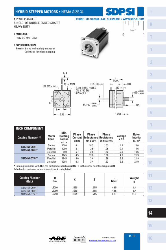
HYBRID STEPPER MOTORS • NEMA SIZE 34
MotorConn.
Min.HoldingTorqueozf in.
Phase Current
amps
PhaseInductance
mH ± 20%
PhaseResistanceohms ± 10%
RotorInertiaoz. in.2
VoltageV DC
SeriesParallelUnipolarSeries
ParallelUnipolar
12001200850
184518451305
4.18.15.74.59.06.3
10.32.62.6
13.63.43.4
1.03.26.52
1.06.26
1.53
4.22.12.94.82.39.6
14.614.614.621.921.921.9
Catalog Number *∆
INCH COMPONENT
S9134M-D60HTS9134M-S60HT
S9134M-D75HT
* Catalog Numbers with D in the suffix have double shafts; S in the suffix denotes single shaft.∆ To be discontinued when present stock is depleted.
DDia. K T L
Max.Weight
g
.5000
.5000
.6250
.1250
.1250
.1875
.555
.555
.705
4.654.656.17
8.48.4
11.9
Catalog Number (Ref.)
S9134M-D60HTS9134M-S60HTS9134M-D75HT
K
T
3.38
18 in. MIN.Ø.218 THRU HOLESON 2.740 SQ.4 PLACES
.2-.4
L MAX.
1.12 ± .06Ø2.875 ± .002
1.250
.875
ØD+.0000 -.0005
Ø.3750 +.0000 -.0005
.330.062
1.8° STEP ANGLESINGLE- OR DOUBLE-ENDED SHAFTSHEAVY-DUTY
VOLTAGE: 160V DC Max. Drive
SPECIFICATION: Leads - 8 (see wiring diagram page) Optimized for microstepping
SDPSI I
I IIIIIII I
\ \ \ 1 1 \
‘ \ _
\ \
\ .
.... . .... -...
... \
\
N N 1 1 1 \
N N .
I
R
1
2
3
4
5
6
7
8
9
10
11
12
13
T
14
15
1614-20
PHONE: 516.328.3300 • FAX: 516.326.8827 • WWW.SDP-SI.COM
0 1Inch
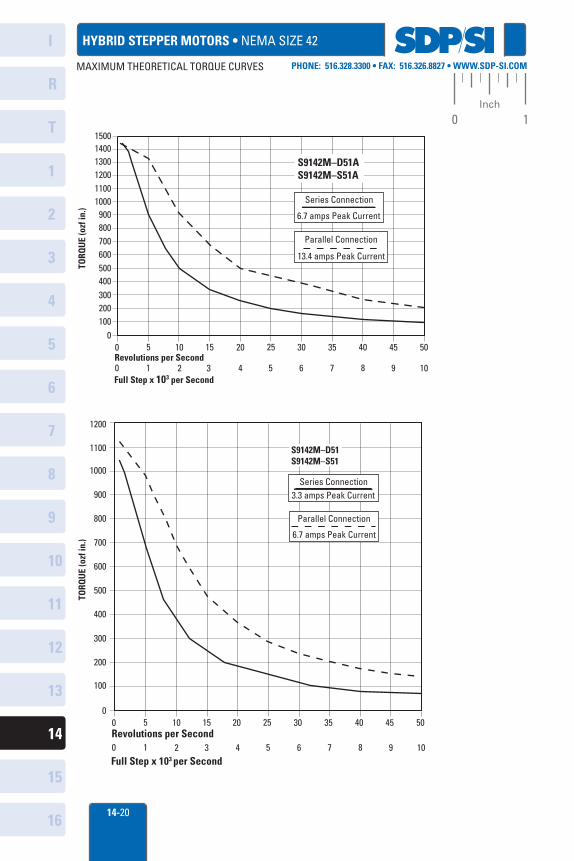
HYBRID STEPPER MOTORS • NEMA SIZE 42
14001300120011001000
900800700600500400300200100
00 5 10 15 20 25 30 35 40 45 50
TORQ
UE
(ozf
in.)
Full Step x 103 per Second0 1 2 3 4 5 6 7 8 9 10Revolutions per Second
1500
S9142M–D51AS9142M–S51A
13.4 amps Peak Current
Parallel Connection
Series Connection
6.7 amps Peak Current
800
700
600
500
300
200
100
00 5 10 15 20 25 30 35 40 45 50
TORQ
UE
(ozf
in.)
400
900
1000
1100
1200
S9142M–D51S9142M–S51
3.3 amps Peak CurrentSeries Connection
6.7 amps Peak Current
Parallel Connection
0 1 2 3 4 5 6 7 8 9 10
Revolutions per Second
Full Step x 103 per Second0 1 2 3 4 5 6 7 8 9 10
MAXIMUM THEORETICAL TORQUE CURVES
sorry ■ IIIIIII1
, , _t 7 4
I
R
1
2
3
4
5
6
7
8
9
10
11
12
13
T
14
15
1614-21
PHONE: 516.328.3300 • FAX: 516.326.8827 • WWW.SDP-SI.COM
0 1Inch
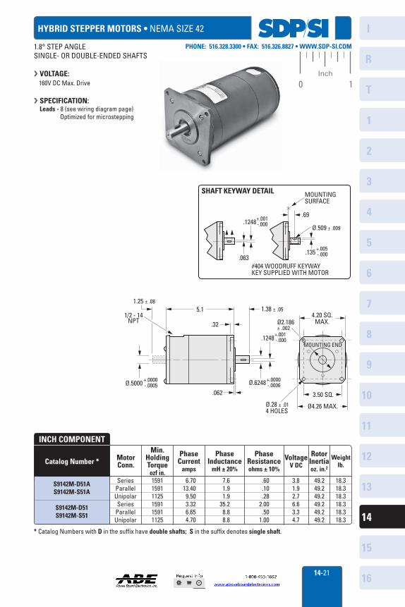
HYBRID STEPPER MOTORS • NEMA SIZE 42
MotorConn.
Min.HoldingTorqueozf in.
Phase Current
amps
PhaseInductance
mH ± 20%
PhaseResistanceohms ± 10%
VoltageV DC
RotorInertiaoz. in.2
Weightlb.
SeriesParallelUnipolarSeries
ParallelUnipolar
159115911125159115911125
6.7013.40
9.503.326.654.70
7.61.91.9
35.28.88.8
.60
.10
.282.00
.501.00
3.81.92.76.63.34.7
49.249.249.249.249.249.2
18.318.318.318.318.318.3
Catalog Number *
INCH COMPONENT
S9142M-D51AS9142M-S51A
S9142M-D51S9142M-S51
* Catalog Numbers with D in the suffix have double shafts; S in the suffix denotes single shaft.
4.20 SQ.MAX.
3.50 SQ.
Ø4.26 MAX.Ø.28 ± .014 HOLES
Ø2.186± .002
.062
.32
1.38 ± .051/2 - 14
NPT
1.25 ± .085.1
MOUNTING END.1248
Ø.6248+.0000 -.0006Ø.5000 +.0000
-.0005
+.001 -.000
Ø.509 ± .009.1248
.063
MOUNTING SURFACE
.69
#404 WOODRUFF KEYWAYKEY SUPPLIED WITH MOTOR
SHAFT KEYWAY DETAIL
+.001 -.000
+.005 -.000.135
1.8° STEP ANGLESINGLE- OR DOUBLE-ENDED SHAFTS
VOLTAGE: 160V DC Max. Drive
SPECIFICATION: Leads - 8 (see wiring diagram page) Optimized for microstepping
sops"
O
-30 (Y\
I
R
1
2
3
4
5
6
7
8
9
10
11
12
13
T
14
15
1614-22
PHONE: 516.328.3300 • FAX: 516.326.8827 • WWW.SDP-SI.COM
0 1Inch
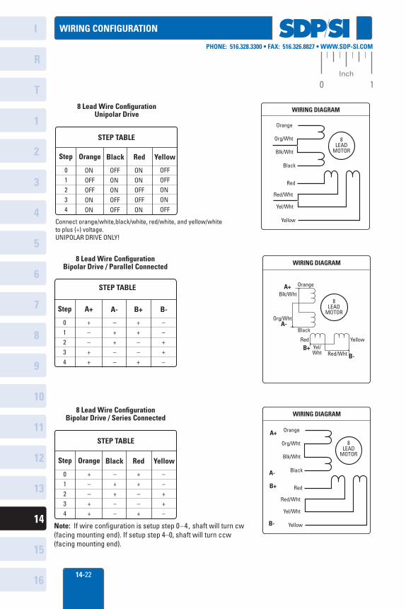
WIRING CONFIGURATION
WIRING DIAGRAM
8LEAD
MOTOR
Orange
Org/Wht
Blk/Wht
Black
Red
Red/Wht
Yel/Wht
Yellow
8LEAD
MOTOR
Orange
Org/Wht
Blk/Wht
Black
Red
Red/Wht
Yel/Wht
Yellow
WIRING DIAGRAM
B+
B-
A-
A+
WIRING DIAGRAM
8LEAD
MOTOR
Orange•
•
••
Blk/Wht
Org/Wht
Black
RedYel/Wht Red/Wht
Yellow
A+
A-
B+B-
STEP TABLE
Step A+ A- B+ B-
01234
+––++
–++––
++––+
––++–
8 Lead Wire Configuration Bipolar Drive / Parallel Connected
STEP TABLE
Step Orange Black Red Yellow
01234
ONOFFOFFONON
OFFONONOFFOFF
ONONOFFOFFON
OFFOFFONONOFF
8 Lead Wire Configuration Unipolar Drive
Connect orange/white,black/white, red/white, and yellow/whiteto plus (+) voltage.UNIPOLAR DRIVE ONLY!
STEP TABLE
Step Orange Black Red Yellow
01234
+––++
–++––
++––+
8 Lead Wire Configuration Bipolar Drive / Series Connected
––++–
Note: If wire configuration is setup step 0–4, shaft will turn cw(facing mounting end). If setup step 4–0, shaft will turn ccw(facing mounting end).
sops ■
-P. ...I-
-t-
i
I
R
1
2
3
4
5
6
7
8
9
10
11
12
13
T
14
15
1614-23
PHONE: 516.328.3300 • FAX: 516.326.8827 • WWW.SDP-SI.COM
0 1Inch
A 3Z16-0005CA 3Z16-0010CA 3Z16-0015CA 3Z16-0020CA 3Z16-0040CA 3Z16-0050CA 3Z16-0070CA 3Z16-0085CA 3Z16-0160CA 3Z16-0200CA 3Z16-0250CA 3Z16-0300CA 3Z16-1150C
A 3Z16-0005BA 3Z16-0010BA 3Z16-0015BA 3Z16-0020BA 3Z16-0040BA 3Z16-0050BA 3Z16-0070BA 3Z16-0085BA 3Z16-0160BA 3Z16-0200BA 3Z16-0250BA 3Z16-0300BA 3Z16-1150B
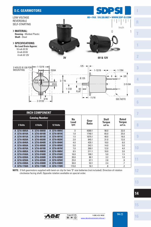
Catalog Number
INCH COMPONENT
StallTorqueozf in.
No Loadrpm
GearRatio
RatedTorqueozf in.
A 3Z16-0005AA 3Z16-0010AA 3Z16-0015AA 3Z16-0020AA 3Z16-0040AA 3Z16-0050AA 3Z16-0070AA 3Z16-0085AA 3Z16-0160AA 3Z16-0200AA 3Z16-0250AA 3Z16-0300AA 3Z16-1150A
.51.01.52.04.05.07.08.5
16.020.025.030.0
115.0
4300:11740:11075:1
845:1435:1342:1269:1211:1109:1
86:167:153:116:1
90.065.040.031.018.014.012.010.0 5.0
3.2 2.8 2.4 .8
32.025.016.012.0 6.0 5.0 4.0 3.0 1.5 1.0 .9 .7 .2
LOW VOLTAGEREVERSIBLESELF-STARTING
MATERIAL: Housing - Molded Plastic Shaft - Steel
SPECIFICATIONS: No Load Drain Approx: 10 mA @ 3V 8 mA @ 6V 4 mA @ 12V
D.C. GEARMOTORS
2 HOLES Ø.130 FOR MOUNTING
.014 FLAT
2-1/16
3/16
1-13/1633/64
Ø3/8
2-27/32
1-1/32 .50 FLAT
Ø.125
11/16
.125
1-13/16 1-7/64
6 3/8
2-51/64
SEE NOTE
NOTE: 3 Volt gearmotors supplied with twist-on clip for two "D" size batteries (not included). Direction of rotation clockwise facing shaft. Opposite rotation available on special order.
3V
3 Volts 6 Volts 12 Volts
6V & 12V