5: capacitors - university of rochesterberdine/phy114/lectures/5-capacitors.pdf · happens when you...
TRANSCRIPT

5: Capacitors July 8, 2008
5.1 Definition
A capacitor is a structure which has a certain capacity to hold an electriccharge. It is essentially the simplest possible battery. The typical exampleof a capacitor, and the typical actual design, is two parallel charged plates.There are variations and clever extensions, but this is the basic idea, andwe’ll see why.
The capacity to store charge is defined in relation to the electrical po-tential necessary for a given amount of charge. Theoretically, any materialobject can store an almost unlimited number of electrons and it doesn’tmatter what the material is made of: you can pack electrons anywhere.However, when you build up larger and larger charges on things, you createfields and the charge starts looking for some way to escape. This is whathappens when you build up a charge and get zapped when you reach for thedoorknob. Your body has built up a charge, which gives rise to a potentialdi!erence between you and the door. When you stand far away, you havethe capacitance to hold on to that charge. However, when you reach for thedoorknob, you reduce the barrier for the charge to jump: you no longer havethe capacity to hold on to all of that charge. In the language of capacitors,the capacitance of the system consisting of your body and the doorknob hasdropped below the charge stored on your body, and the capacitor (yes, youand the doorknob form a capacitor) discharges.
But this is physics class, lets see some equations! The quantification ofthe above is simple. Capacitance is the amount of charge a system can holdbe Volt of potential di!erence:
C =Q
V[C] = C
V = F = farad
(Don’t you just love how all of these things start o! with innocuous,simple definitions, and then turn out to have the potential for unlimitedcomplexity and headaches? Perhaps you find this annoying, but its that
58

Figure 5.1: Parallel Plate Capacitor
tendency of simple physical systems to give rise to ridiculously complex be-havior that makes the universe an interesting place with the dizzying varietyof objects and life and phenomena. OK, end of pointless aside. Sorry.)
A 1F capacitor can hold an entire Coulomb of charge with only a singleVolt of potential di!erence. Most of the capacitors in everyday electronicsare measured in microfarad (µF ).
That’s all there is to the definition of a capacitor. They can take anyshape, and in fact any shape is a capacitor, but certain shapes make muchbetter capacitors than others, which is why the parallel plate capacitor is socommon.
5.2 Examples
Any system with two objects between which you can find the potential dif-ference can be analytically studied as a capacitor. There are many objectsfor which this calculation is impossible or impractical, in which case exper-iment can discern the capacitance, but we have plenty of examples we canconsider.
5.2.1 Parallel Plate Capacitor
The parallel plate capacitor is that rare example in which case the one of themost easily solved problems actually looks a lot like the practical physicalmanifestation. Enjoy the novelty.
59

The definition of capacitance depends only on the charge held and thecorresponding potential. For the parallel plate capacitor this is easily solved.Construct our system of 2 conducting plates. Each holds charge Q and is aplate of unspecified shape (within reason. Its not a cheese grater with holesnor a snowflake cutout with lots of corners) but with area A. This is all weneed to calculate the potential di!erence. The positive charge is on the plateat point b.
Vb ! Va = !ˆ b
a
!E · d!" = !E
ˆ 0
ddx = Ed
Remember from solving for the field near a charged plane with Gauss’sLaw that
E =Q
#0
1A
soVba =
Qd
#0A
C =Q
Vba= #0
A
d
60

5.2.2 Cylindrical Capacitor
Figure 5.2:
61

Figure 5.3:
C = 2$#0L
ln(R2/R1)
Compare this to the case for the parallel plates. The length of the cylindertakes the place of the area (both give a measure of the size of the capacitor.The cylindrical capacitor is like the line charge to a parallel plate capacitor’ssurface charge) while the natural log of the ratio of the radii takes the place ofthe separation d (both give a measure of the separation of the charge carryingsurfaces). Note that because the natural logarithm is a very slowly varyingfunction, the cylindrical configuration doesn’t gain capacitance nearly as wellas the parallel plates by being brought close together.
62
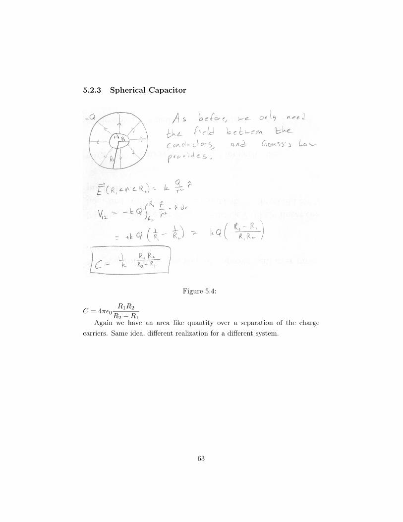
5.2.3 Spherical Capacitor
Figure 5.4:
C = 4$#0R1R2
R2 !R1Again we have an area like quantity over a separation of the charge
carriers. Same idea, di!erent realization for a di!erent system.
63

5.2.4 Parallel Wires
Figure 5.5:
C = 2$#0L
ln(d!!/!)
This looks an awful lot like the cylindrical capacitor case, doesn’t it?
64

They both have a cylindrical symmetry, so this shouldn’t surprise you en-tirely.
5.3 Putting Capacitors Together: The Beginning ofCircuits
Generally in the context of a purpose-built capacitor (rather than some ran-dom collection of objects which has a capacitance), the potential di!erencebetween the plates is maintained by wires connected to each and some sortof power source such as a battery or a generator. Since each capacitor isthen connected to a wire on each end, it can be integrated into a circuit(which is just a loop which conducts and has a power source to drive it).We can wire capacitors together in 2 di!erent ways: series and parallel. Aseries connection just means sticking one capacitor after the other in a line.More specifically, the positive lead from one capacitor leads into the negativelead of the next, and so on. In a parallel connection, the positive leads of anumber of capacitors are all wired together, and the negative leads of all thesame capacitors are also wired together.
These two di!erent arrangements make for very di!erent behaviors. For-tunately, we can calculate them!
Figure 5.6: Capacitors in Parallel
Imagine first that I connect 3 capacitors C1, C2, C3 in parallel. Becausetheir positive and negative leads are connected, they all have the same po-tential di!erence V!+ across them. The question we want to answer, is whatis the equivalent capacitance of this collection of capacitors? That is, what
65

would the capacitance of a single capacitor need to be to function like thiscollection of 3. Remember, any system has a capacitance, so there has to besome capacitance that is equivalent to the 3 in parallel.
We know the voltage (potential di!erence) for each is the same, so allthat remains is to find the total charge:
Q = Q1 + Q2 + Q3 = C1V!+ + C2V!+ + C3V!+ = V!+ (C1 + C2 + C3)With the definition of capacitance, this gives:Cequiv = C1 + C2 + C3
Note that despite its similarity to expressions of the principal of super-position, this is result does not in fact follow (at least in any reasonably clearway) from that principal. We can make sense of this result by thinking interms of parallel plate capacitors, however. In that case, the capacitanceis proportional to the are of the capacitors. If we just stick a couple ofcapacitors in parallel, we are essentially adding their areas, so the capaci-tance would also add. This is just a plausibility argument, however, since itneglects the plate separation and other configurations of capacitor.
Figure 5.7: Capacitors in Series
That was easy enough. What about capacitors in a series? Again letswork with 3 capacitors. Since they are in series, they no longer have the samepotential di!erence across them (necessarily). However, we know that theirpotential di!erences must add up to the total maintained potential di!erence,V!+. Why? Because the circuit is a complete loop and the electric potentialcan’t have discontinuities. So, the power supply provides a potential jumpof V!+. The rest of the circuit (in this case the 3 capacitors) must bring us
66

all the way back down (but no further) so that the potential matches up.V!+ = !V1 + !V2 + !V3
The notation !Vi refers to the potential di!erence between the two platesof capacitor Ci. Writing Vi would be ambiguous given our previous use ofthat symbol.
Looking at Fig[5.7], we can see that the charge on each capacitor mustbe the same. Why is this? The applied voltage from the wire connected tothe negative lead of C1 will induce some charge !Q on C1. This charge mustinduce an equal and opposite charge on the other plate, giving Q. Becausethere is a wire connecting C1 and C2, the + side of C1 must have the sameelectric potential as the ! side of C2. Equal potential means even chargedistribution in a conductor, so C2 must also have charge Q. Likewise, wesee that C3 has charge Q.
We can now use the definition of capacitance to giveC = Q
V !"1C = V
Q !"1
C1+ 1
C2+ 1
C3= !V1
Q + !V2Q + !V3
Q1
C1+ 1
C2+ 1
C3= 1
Q (!V1 + !V2 + !V3) = V!+
Q = Cequiv1
Cequiv= 1
C1+ 1
C2+ 1
C3
Quite di!erent from the addition rule for a parallel arrangement! In fact,the equivalent capacitance in series is smaller than the smallest capacitorin the series. This is not what you do if you are looking to build up a bigcapacitance in your circuit.
5.4 Energy Stored in Capacitors
We learned earlier that we can calculate the work required to construct asystem of charges using the scalar potential. We found that
U =ˆ
dU =ˆ Q
0V dq
Rather than use the explicit expression in terms of charge and separationfor the scalar potential, we can write it in terms of the capacitance,
V = QC #
qC
where q in the integral will be how much charge we’ve already added up,
U =ˆ Q
0
q
Cdq =
1C
ˆ Q
0qdq =
1C
Q2
2
67

U = 12
Q2
C
We can write this another way by simply substituting in for Q:U = 1
2CV 2 = 12QV
5.4.1 Electric Field
I made a bit of a point when I introduced the electric field that it hasa physical existence and isn’t just a mathematical trick. This is the firstplace we see real evidence for that, and the evidence is that the electricfield itself is the entity which contains the energy stored in a capacitor!This invisible, intangible “object” is storing energy in the gap between twoconducting plates.
Combining the expression for the potential energy content of a capacitor,U = 1
2CV 2 and the parallel plate expression for electric potential V = Ed,we find
U = 12
!0Ad E2d2 = 1
2#0AdE2
If we note that Ad is the volume between the capacitor’s plates, we candefine an energy density between the plates,
u = UAd = 1
2#0E2
This turns out to be a general expression for the energy density of anelectric field (where it is constant), tho we derived it from this special case.
5.4.2 Examples
Pull capacitor plates apart
Pull plates apart while plugged in
5.5 Dielectrics (and Insulators)
Experimentally, we find that we can dramatically increase the capacitanceof a system by inserting insulating materials between the charged surfaces.Your book has a section which explains how this works at a microscopiclevel, but the basic idea is just that even insulators have a kind of inducedcharge which reduces the field in a capacitor. This reduced field, with thesame charge buildup, means that the charges feel less motivation to leap from
68
one plate to the other, discharging out capacitor. And because dielectrics(materials which have this type of induced charge) are also (often) insulators,they also keep the electrons on their own side even if the field is cranked upextra high. Since this whole process depends upon complex molecular levelphysics of an aggregate material, we don’t even pretend to try and calculateit (well, we don’t. Professionals with huge computers and such do). Instead,we just look up measured values from experiment.
This e!ect can be described with a single constant (for each material)factor:
C = KC0
where C0 is the capacitance we have been calculating so far and corre-sponds to a vacuum existing between the plates. Air’s dielectric constant K
is almost exactly the same as that of the vacuum (1.0006 rather than 1), soeverything we’ve done works for most purposes in atmosphere as well.
For reasons we won’t get into, the dielectric constant is often rolled intoanother parameter
# = K#0
#0 is the permittivity of free space (vacuum), while # is the permittivityof whatever material we are worried about at the moment. The upshot ofthis is that if you’ve done a calculation for a capacitor in vacuum and wantto turn it into one with a dielectric, you can just replace #0 with #.
Functionally, this constant increases the capacitance of a system.SinceK is always 1 or larger, it increases the charge required to produce a givenvoltage.
Q = KQ0
and it increases the energy contained in a conductor,u = Ku0 = 1
2#E2.However, the electric field is decreasedE = E0
K
as is the potential di!erenceV = V0
K
These make sense because the point of the dielectric is to reduce theforces pulling the electrons from one surface to the other.
69