5 effective stress concept
TRANSCRIPT

University of Anbar College of Engineering Civil Engineering Department Iraq-Ramadi
Asst. Prof. Khalid R. Mahmood (PhD.)
215
Effective Stress Concept
Topics Effective Stress Concept Effective Stress in Saturated Soil with
no Seepage Effective Stress in Saturated Soil with
Seepage Seepage Force Filter Requirements and Selection of Filter Material Capillary Rise in Soil Effective Stress in Capillary Zone
Water
Water Table (W.T.)
Ground Surface (G.S.) Air
Voids
Solid

University of Anbar College of Engineering Civil Engineering Department Iraq-Ramadi
Asst. Prof. Khalid R. Mahmood (PhD.)
216
Effective Stress Concept • Soil is a multi phase system • To perform any kind of analysis - we must understand stress distribution • The concept of effective stress:
• The soil is “loaded” (footing for example) • The resulting stress is transmitted to the soil mass • The soil mass supports those stresses at the point to point contacts of the individual soil grains

University of Anbar College of Engineering Civil Engineering Department Iraq-Ramadi
Asst. Prof. Khalid R. Mahmood (PhD.)
217
The total stress at A is calculated from: The weight of the soil above A The weight of the water above A = H w + (HA - H) sat = Total Stress at A w = Unit Weight of Water sat = Saturated Unit Weight HA = Height of A to Top of water H = Height of water

University of Anbar College of Engineering Civil Engineering Department Iraq-Ramadi
Asst. Prof. Khalid R. Mahmood (PhD.)
218
• is the stress applied to the soil by its own weight • As you go deeper in the soil mass, the stress increases • The soil carries the stress in 2 ways:
• A portion is carried by the water (acts equally in all directions)
• A portion is carried by the soil solids at their point of contact.

University of Anbar College of Engineering Civil Engineering Department Iraq-Ramadi
Asst. Prof. Khalid R. Mahmood (PhD.)
219
/= (P1v+P2v+P3v .....+Pnv) / A If as = a1 + a2 + a3 +...an Then the space occupied by water = A - as Assume u = HA w HA = Height of water
= / + u(A - as) / A

University of Anbar College of Engineering Civil Engineering Department Iraq-Ramadi
Asst. Prof. Khalid R. Mahmood (PhD.)
220
Since as is very small, assume = 0 = / + u
Recall the following equation: = H w + (HA - H) sat
Now, / = - u Substituting: / = [H w + (HA - H) sat] - HA w Rearranging: / = (HA - H)( sat - w) = Hsoil
/ Effective Stress is independent of height of water In the equation: = / + u
/ is the soil skeleton stress u is the stress in the water, or pore water pressure

University of Anbar College of Engineering Civil Engineering Department Iraq-Ramadi
Asst. Prof. Khalid R. Mahmood (PhD.)
221
Effective Stress in Saturated Soil with no Seepage

University of Anbar College of Engineering Civil Engineering Department Iraq-Ramadi
Asst. Prof. Khalid R. Mahmood (PhD.)
222
Effective Stress in Saturated Soil with Seepage
Upward flow

University of Anbar College of Engineering Civil Engineering Department Iraq-Ramadi
Asst. Prof. Khalid R. Mahmood (PhD.)
223
Note that the h/H2 is the hydraulic gradient that caused flow therefore,
wc izz And limiting conditions may occur when 0wc izz which lead to icr = critical hydraulic gradient
wcri
for most soils 0.9-1.1 ith average value of 1

University of Anbar College of Engineering Civil Engineering Department Iraq-Ramadi
Asst. Prof. Khalid R. Mahmood (PhD.)
224
Downward flow

University of Anbar College of Engineering Civil Engineering Department Iraq-Ramadi
Asst. Prof. Khalid R. Mahmood (PhD.)
225
Seepage Force
Azp1
AizforceseepageforceseepagepAizzp
w
w 12 )(
AizforceseepageforceseepagepAizzp
w
w 33 )(

University of Anbar College of Engineering Civil Engineering Department Iraq-Ramadi
Asst. Prof. Khalid R. Mahmood (PhD.)
226
The volume of the soil contributing to the effective stress force equals zA, so the seepage force per unit volume of the soil is
ww i
zAAiz
in the direction of seepage (see the fig.) Therefore, in isotropic soil and in any direction, the force acts in the same direction as the direction of flow. Thus, the flow nets can be used to find the hydraulic gradient at any point to find seepage force at that point. This concept is useful to estimate F.S against heave
University of Anbar College of Engineering Civil Engineering Department Iraq-Ramadi
Asst. Prof. Khalid R. Mahmood (PhD.)
227
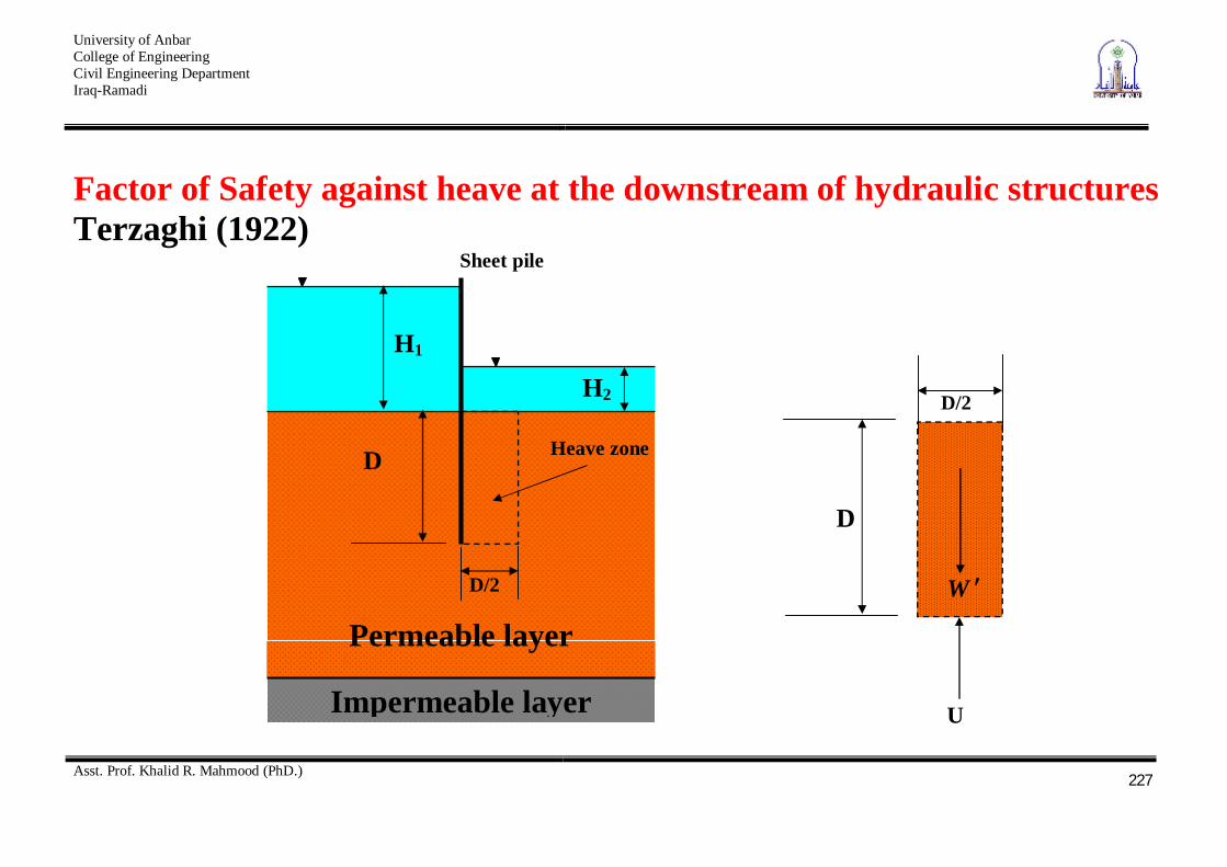
Factor of Safety against heave at the downstream of hydraulic structures Terzaghi (1922)
H1
H2
Sheet pile
Impermeable layer
Permeable layer
D
D/2
D
D/2
W
U
Heave zone

University of Anbar College of Engineering Civil Engineering Department Iraq-Ramadi
Asst. Prof. Khalid R. Mahmood (PhD.)
228
wavwav
wav
wsat
iiD
D
ixvolumesoilDD
UW
seepagebycausedforceUpliftweightSubmergedSF
2
2
21
21
)())(2/(.

University of Anbar College of Engineering Civil Engineering Department Iraq-Ramadi
Asst. Prof. Khalid R. Mahmood (PhD.)
229
Estimation of iav
a b c
e d
nd = 10
Dri
ving
hea
d
a b c

University of Anbar College of Engineering Civil Engineering Department Iraq-Ramadi
Asst. Prof. Khalid R. Mahmood (PhD.)
230
point driving head
a H104
b H
107.6
c H
105.2
Dhi
hhhh
avav
bcaav 2
2/)(

University of Anbar College of Engineering Civil Engineering Department Iraq-Ramadi
Asst. Prof. Khalid R. Mahmood (PhD.)
231
Filter Requirements and Selection of Filter Material In practice, for the safe of the hydraulic structure, a minimum value of 4 to 5 for F.S against heaving is used, because of the uncertainty in the analysis. One way to increase the F.S is using filter. Filter:- is a granular material with opening small enough to
prevent the movement of the soil particles upon which is placed and, at the same time, is previous enough to offer little resistance to seepage through it.

University of Anbar College of Engineering Civil Engineering Department Iraq-Ramadi
Asst. Prof. Khalid R. Mahmood (PhD.)
232
a b c
e d
nd = 10
D
D/2
WW
U
D1

University of Anbar College of Engineering Civil Engineering Department Iraq-Ramadi
Asst. Prof. Khalid R. Mahmood (PhD.)
233
wav
F
wav
FF
iDD
iD
DDD
UWWSF
1
2
12
21
21
21
.

University of Anbar College of Engineering Civil Engineering Department Iraq-Ramadi
Asst. Prof. Khalid R. Mahmood (PhD.)
234
Selection of Filter Material Capillary R

University of Anbar College of Engineering Civil Engineering Department Iraq-Ramadi
Asst. Prof. Khalid R. Mahmood (PhD.)
235
Capillarity rise in Soil

University of Anbar College of Engineering Civil Engineering Department Iraq-Ramadi
Asst. Prof. Khalid R. Mahmood (PhD.)
236
For pure water and clean glass = 0
wc d
Th 4
For water T = 72 m.N/m
dhc
1
the smaller the capillarity tube, the larger capillary rise

University of Anbar College of Engineering Civil Engineering Department Iraq-Ramadi
Asst. Prof. Khalid R. Mahmood (PhD.)
237
For soils, the capillary tubes formed because of the continuity of voids have variable cross sections. The results of the nonuniformity on capillary can be demonstrated as shown in the fig.
Variation of S in the soil

University of Anbar College of Engineering Civil Engineering Department Iraq-Ramadi
Asst. Prof. Khalid R. Mahmood (PhD.)
238
Hazen (1930) give a formula to estimate the height of capillary
10
)(eD
Cmmh c

University of Anbar College of Engineering Civil Engineering Department Iraq-Ramadi
Asst. Prof. Khalid R. Mahmood (PhD.)
239
Effective Stress in Capillary Zone The general relationship of effective stress is u
For soil fully saturated by capillary wchu
For soil partially saturated by capillary wchSu100

University of Anbar College of Engineering Civil Engineering Department Iraq-Ramadi
Asst. Prof. Khalid R. Mahmood (PhD.)
240
Examples EXAMPLE1. Plot the variation of total and effective vertical stresses, and pore water pressure with depth for the soil profile shown below in Fig.

University of Anbar College of Engineering Civil Engineering Department Iraq-Ramadi
Asst. Prof. Khalid R. Mahmood (PhD.)
241

University of Anbar College of Engineering Civil Engineering Department Iraq-Ramadi
Asst. Prof. Khalid R. Mahmood (PhD.)
242
University of Anbar College of Engineering Civil Engineering Department Iraq-Ramadi
Asst. Prof. Khalid R. Mahmood (PhD.)
243
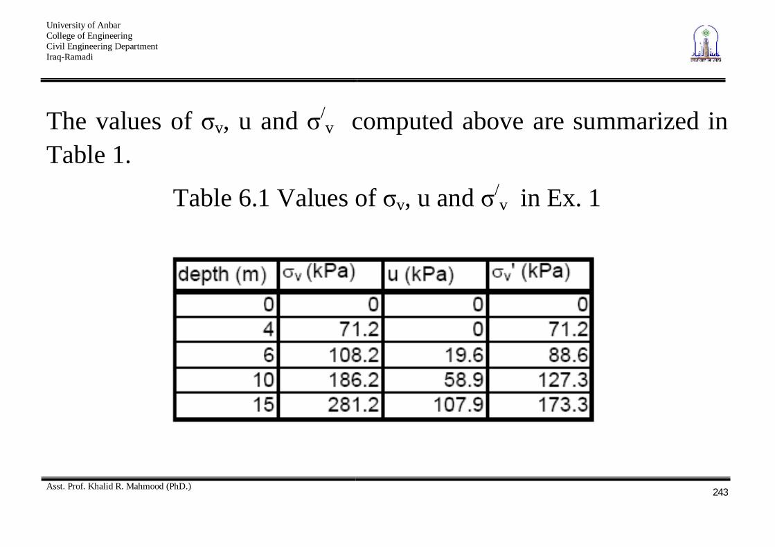
The values of v, u and /v computed above are summarized in
Table 1.
Table 6.1 Values of v, u and /v in Ex. 1

University of Anbar College of Engineering Civil Engineering Department Iraq-Ramadi
Asst. Prof. Khalid R. Mahmood (PhD.)
244
EXAMPLE2. Plot the variation of total and effective vertical stresses, and pore water pressure with depth for the soil profile shown below in Fig.
Dry Sand
Gs = 2.66
Moist Sand Zone of capillary rise
Gs = 2.66
Saturated Clay
= 42%
A
H1 = 2 m
B
H2 = 1.8 m
C
H3 = 3.2 m
G.W.
Rock

University of Anbar College of Engineering Civil Engineering Department Iraq-Ramadi
Asst. Prof. Khalid R. Mahmood (PhD.)
245
Dry sand 84.1681.955.01
66.2e1
Gw
sd kN/m3
Moist sand 58.1881.955.01
55.0*5.066.2e1SeG
ws
t kN/m3
Saturated Clay 138.1
142.0*71.2
SGe s
66.1781.9138.11
138.166.2e1eG
ws
sat kN/m3

University of Anbar College of Engineering Civil Engineering Department Iraq-Ramadi
Asst. Prof. Khalid R. Mahmood (PhD.)
246
Point v kN/m2 u kN/m2 /v kN/m2
A 0 0 0
0 33.68 B 2*16.84=33.68 - S w H2 = - 0.5*9.81*1.8 =
- 8.83 33.68-(-8.83) =
42.51
C 2*16.84+1.8*18.58 = 67.117 0 67.117
D 2*16.84+1.8*18.58+3.2*17.66 =123.68 3.2*9.81=31.39 123.68-31.39 = 92.24

University of Anbar College of Engineering Civil Engineering Department Iraq-Ramadi
Asst. Prof. Khalid R. Mahmood (PhD.)
247
The plot is shown below in Fig.
Variation of v, u and /v with depth
0
1
2
3
4
5
6
7
8
-20 -10 0 10 20 30 40 50 60 70 80 90 100 110 120 130 140
Stress, kN/m2
dept
h, (m
)
Total stress
Pore water pressure
Effective stress