5 heat exchanger - pegasus glass - custom · pdf file5.3 heat exchanger 2002 glass components...
TRANSCRIPT
5 HEAT EXCHANGER
PROCESS PLANT COMPONENTS
P 305 e.1
5.2
HEAT EXCHANGER
2002
IntroductionQVF heat exchangers provide the optimum solution for every requirement encounteredin practice because of the wide range of types available. This applies not only to coiltype heat exchangers, which are available as condensers, boilers and immersion heatexchangers, but also to shell and tube heat exchangers, which are designed for usewith tubes in the widest possible range of corrosion resistant materials.
These items are widely used in the chemical, pharmaceutical and allied industriestogether with other applications such as food and drink production, dye works andelectroplating. This is because of the special properties of borosilicate glass 3.3 andall the other materials used plus the fact that borosilicate glass 3.3 is an approved andproven material of construction for pressure vessels.
Reference should also be made in this context to the extreme reliability of the strongand high-duty coupling system used for all components. This is achieved throughoutthe whole range of nominal sizes by the use of the safety buttress end which hasbeen designed specifically by taking into account the properties of the material coupledwith a reliable flange system.
The complete range of standard heat exchanger components is described on the following pages. Non-standard components that can be supplied to special order arereferred to in the respective product description.
A detailed listing of all heat exchangers by »Description« and »Catalogue Reference«can be found in the »Index«.
Detailed information on a number of the topics referred to in the followingpages can be found in Section 1 »Technical Information«.
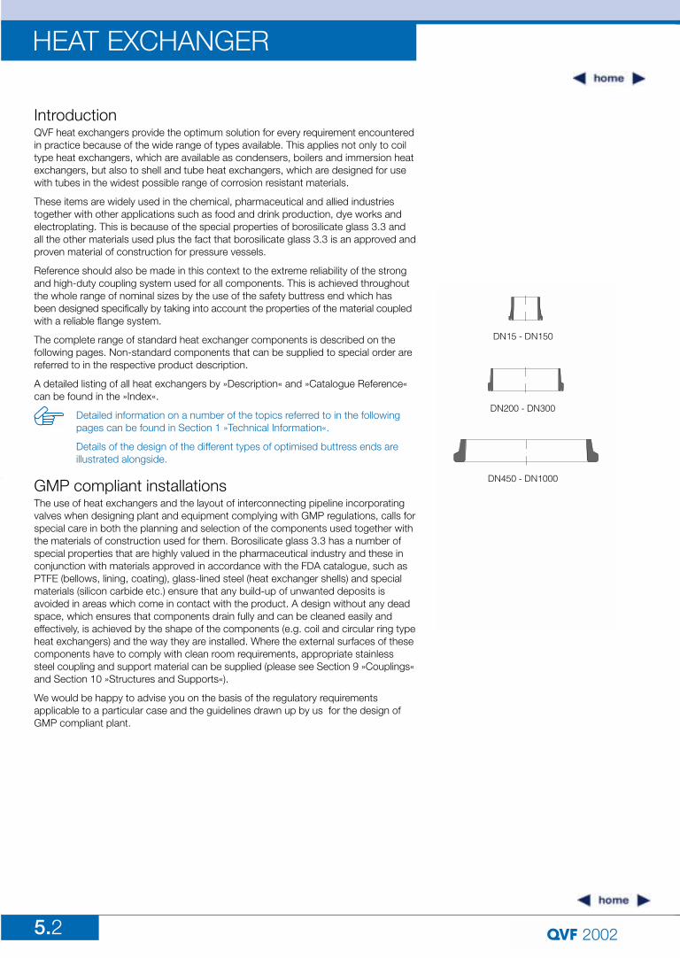
Details of the design of the different types of optimised buttress ends areillustrated alongside.
GMP compliant installationsThe use of heat exchangers and the layout of interconnecting pipeline incorporatingvalves when designing plant and equipment complying with GMP regulations, calls forspecial care in both the planning and selection of the components used together withthe materials of construction used for them. Borosilicate glass 3.3 has a number ofspecial properties that are highly valued in the pharmaceutical industry and these inconjunction with materials approved in accordance with the FDA catalogue, such asPTFE (bellows, lining, coating), glass-lined steel (heat exchanger shells) and specialmaterials (silicon carbide etc.) ensure that any build-up of unwanted deposits is avoided in areas which come in contact with the product. A design without any deadspace, which ensures that components drain fully and can be cleaned easily andeffectively, is achieved by the shape of the components (e.g. coil and circular ring typeheat exchangers) and the way they are installed. Where the external surfaces of thesecomponents have to comply with clean room requirements, appropriate stainlesssteel coupling and support material can be supplied (please see Section 9 »Couplings«and Section 10 »Structures and Supports«).
We would be happy to advise you on the basis of the regulatory requirements applicable to a particular case and the guidelines drawn up by us for the design ofGMP compliant plant.
DN15 - DN150
DN200 - DN300
DN450 - DN1000
5.3
HEAT EXCHANGER
2002
Glass components suitable for higher permissible operating conditions canalso be supplied on request.
Coated heat exchangersDamage to borosilicate glass 3.3 assemblies resulting from accidental external causescannot be entirely excluded, especially in the smaller nominal sizes. This is primarilydue to the relatively rigorous conditions prevalent in production plants and appliesespecially where no additional protection is provided in the form of insulation.
Our answer to this problem is to provide borosilicate glass 3.3 heat exchangers with a Sectrans transparent coating. This can be applied irrespective of the shape of thecomponent and it provides additional protection without having any adverse effect onvisual monitoring of the process.
A glass fibre reinforced polyester coating providing a higher level of protection can also be supplied on request. This does have a slightly adverse effect on the transparency of the glass, making it translucent and not transparent.
Permissible operating conditionsWhile the maximum permissible operating temperature for borosilicate glass 3.3 heat exchanger bodies is generally 200 ºC (!" # 180 K), the maximum permissible operating pressure is governed by the main nominal size of the component but not byits shape. Detailed information on this can be found in Section 1 »Technical Informaton«.
The maximum permissible figures for pressure and temperature gradient across theheat exchange surfaces and PTFE tube plates (between the media) and the permissibleoperating conditions for components in other materials can be found in the respectiveproduct description.
5.4
HEAT EXCHANGER
2002
Unlike the shell and tube heat exchangers described on pages 5.15 to 5.22 theseitems have the coil battery welded to the jacket. This is of importance for plant which has to conform to GMP requirements since it ensures that the product and the coolant cannot come into contact with each other.
Coil type heat exchangers are mainly used as condensers or coolers. They can,however, be used for heat transfer between liquids and gases in general. Turbulentflow is ensured even in the larger nominal bores since the coil layers are offset and fill the flow cross-section to a great extent.
Information on pressure drop in the coils together with performance data which canbe used to estimate the heat transfer surface required can be found on pages 5.6 and5.7. We would be happy to carry out detailed design work for you.
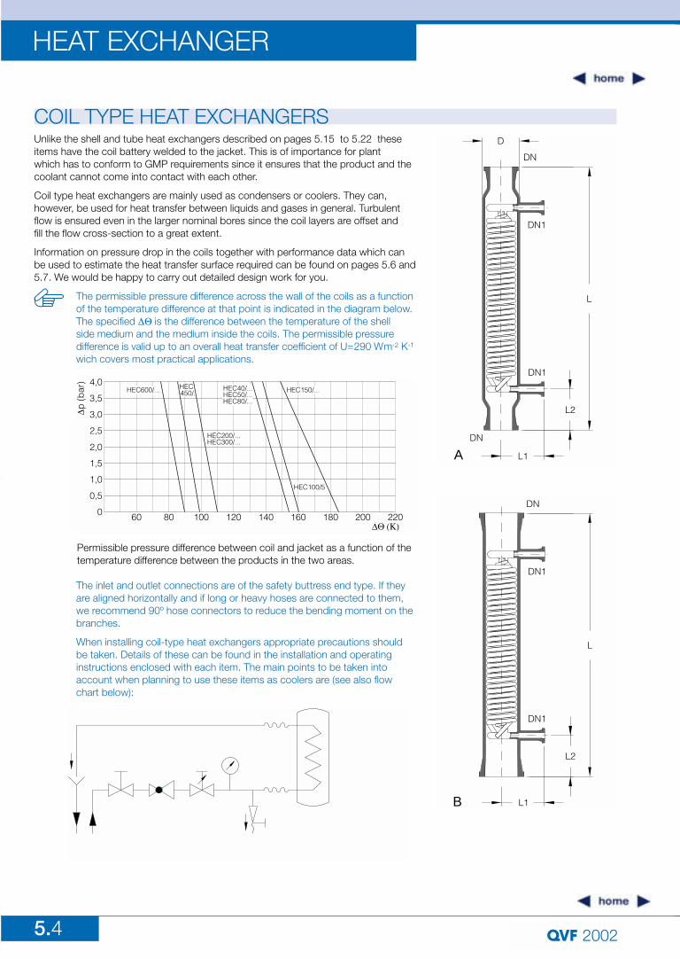
The permissible pressure difference across the wall of the coils as a functionof the temperature difference at that point is indicated in the diagram below.The specified !"$is the difference between the temperature of the shell side medium and the medium inside the coils. The permissible pressure difference is valid up to an overall heat transfer coefficient of U=290 Wm-2 K-1
wich covers most practical applications.
COIL TYPE HEAT EXCHANGERS
Permissible pressure difference between coil and jacket as a function of thetemperature difference between the products in the two areas.
D
DN
DN1
DN1
L
L2
L1
DN
A
DN
DN1
DN1
L
L2
L1B
The inlet and outlet connections are of the safety buttress end type. If theyare aligned horizontally and if long or heavy hoses are connected to them,we recommend 90º hose connectors to reduce the bending moment on thebranches.
When installing coil-type heat exchangers appropriate precautions shouldbe taken. Details of these can be found in the installation and operatinginstructions enclosed with each item. The main points to be taken intoaccount when planning to use these items as coolers are (see also flowchart below):
5.5
HEAT EXCHANGER
2002
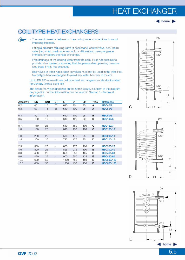
COIL TYPE HEAT EXCHANGERS- The use of hoses or bellows on the cooling water connections to avoid
imposing stresses.
- Fitting a pressure reducing valve (if necessary), control valve, non-return valve (not when used under re-cool conditions) and pressure gauge immediately before the heat exchanger.
- Free drainage of the cooling water from the coils, if it is not possible to provide other means of ensuring that the permissible operating pressure (see page 5.4) is not exceeded.
- Ball valves or other rapid opening valves must not be used in the inlet linesto coil type heat exchangers to avoid any water hammer in the coil.
Up to DN 150 nominal bore coil type heat exchangers can also be installedhorizontally (with a slight fall).
The end form, which depends on the nominal size, is shown in the diagramon page 5.2. Further information can be found in Section 1 »Technical Information«.
DN11515
1515
2525
2525
252525255050
DN4050
80100
150150
200200
300300450450600600
Area (m2)0,20,3
0,30,5
0,71,0
1,01,5
2,54,06,08,012,015,0
ReferenceHEC40/2HEC50/3
HEC80/3HEC100/5
HEC150/7HEC150/10
HEC200/10HEC200/15
HEC300/25HEC300/40HEC450/60HEC450/80HEC600/120HEC600/150
L610610
610610
610840
500725
60082585090011001250
D6085
--
--
--
------
L175100
100125
150150
175175
275275350350450450
TypeAA
BB
CC
DD
EEEEEE
L29595
9580
100100
9595
100100125125150150
DN
DN1
L
DN1
L2
L1E
DN
DN1
L
DN1
L2
L1D
DN
DN1
DN1
L
L2
L1C
Area
(m2)
0,20,30,30,50,71,01,01,52,54,06,08,012,015,0
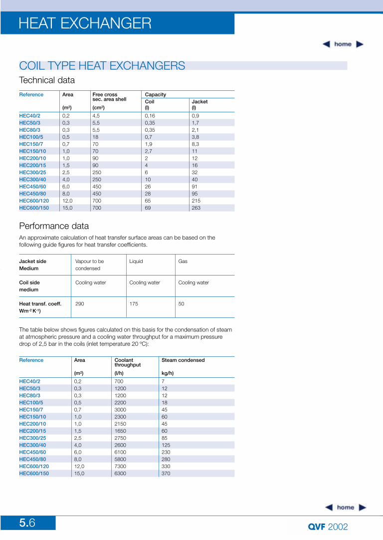
Reference
HEC40/2HEC50/3HEC80/3HEC100/5HEC150/7HEC150/10HEC200/10HEC200/15HEC300/25HEC300/40HEC450/60HEC450/80HEC600/120HEC600/150
Coolantthroughput
(l/h)
7001200120022003000230021501650275026006100580073006300
Steam condensed
kg/h)
71212184560456085125230280330370
5.6
HEAT EXCHANGER
2002
COIL TYPE HEAT EXCHANGERSTechnical data
Performance data
Free cross sec. area shell
(cm2)
4,55,55,51870709090250250450450700700
Area
(m2)
0,20,30,30,50,71,01,01,52,54,06,08,012,015,0
Reference
HEC40/2HEC50/3HEC80/3HEC100/5HEC150/7HEC150/10HEC200/10HEC200/15HEC300/25HEC300/40HEC450/60HEC450/80HEC600/120HEC600/150
Coil(l)
0,160,350,350,71,92,72461026286569
Jacket(l)
0,91,72,13,88,311121632409195215263
Capacity
Vapour to becondensed
Cooling water
290
Jacket side Medium
Coil sidemedium
Heat transf. coeff.Wm-2 K-1)
Gas
Cooling water
50
Liquid
Cooling water
175
An approximate calculation of heat transfer surface areas can be based on the following guide figures for heat transfer coefficients.
The table below shows figures calculated on this basis for the condensation of steamat atmospheric pressure and a cooling water throughput for a maximum pressuredrop of 2,5 bar in the coils (inlet temperature 20 ºC):
5.7
HEAT EXCHANGER
2002
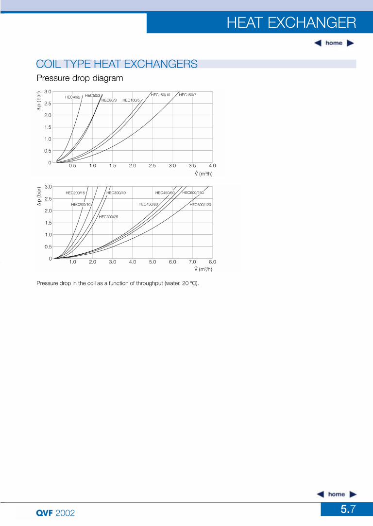
COIL TYPE HEAT EXCHANGERSPressure drop diagram
Pressure drop in the coil as a function of throughput (water, 20 ºC).
5.8
HEAT EXCHANGER
2002
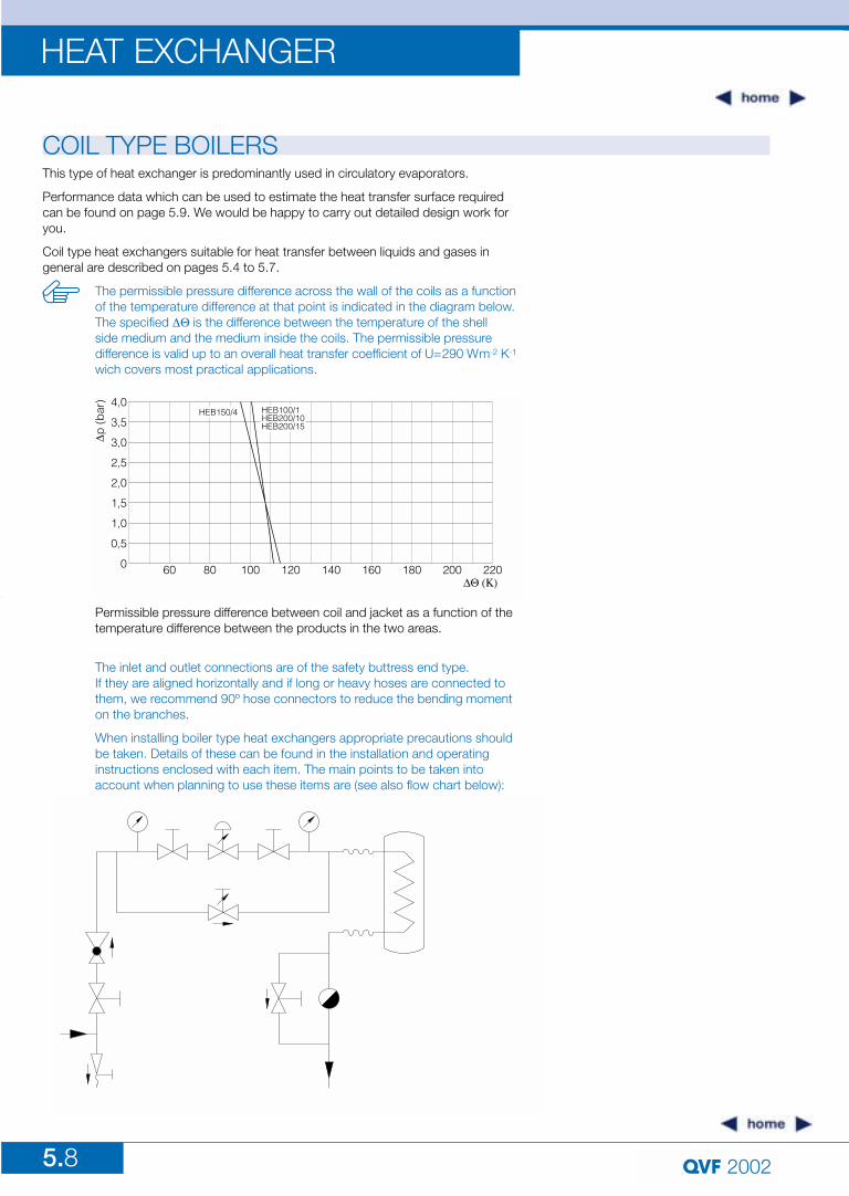
COIL TYPE BOILERSThis type of heat exchanger is predominantly used in circulatory evaporators.
Performance data which can be used to estimate the heat transfer surface requiredcan be found on page 5.9. We would be happy to carry out detailed design work foryou.
Coil type heat exchangers suitable for heat transfer between liquids and gases ingeneral are described on pages 5.4 to 5.7.
The permissible pressure difference across the wall of the coils as a functionof the temperature difference at that point is indicated in the diagram below.The specified !"$is the difference between the temperature of the shell side medium and the medium inside the coils. The permissible pressure difference is valid up to an overall heat transfer coefficient of U=290 Wm-2 K-1
wich covers most practical applications.
Permissible pressure difference between coil and jacket as a function of thetemperature difference between the products in the two areas.
The inlet and outlet connections are of the safety buttress end type. If they are aligned horizontally and if long or heavy hoses are connected tothem, we recommend 90º hose connectors to reduce the bending momenton the branches.
When installing boiler type heat exchangers appropriate precautions shouldbe taken. Details of these can be found in the installation and operatinginstructions enclosed with each item. The main points to be taken intoaccount when planning to use these items are (see also flow chart below):
2002 5.9
HEAT EXCHANGER
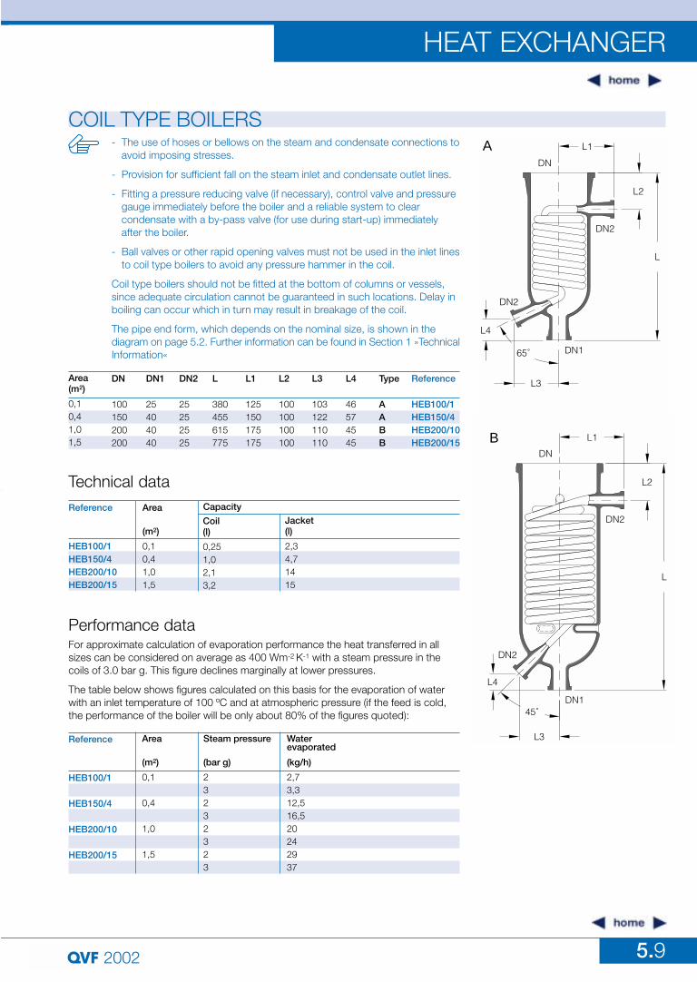
DN
100150200200
DN1
25404040
DN2
25252525
L
380455615775
L1
125150175175
L2
100100100100
L3
103122110110
L4
46574545
Type
AABB
Area (m2)
0,10,41,01,5
Reference
HEB100/1HEB150/4HEB200/10HEB200/15
COIL TYPE BOILERSL1
DN
L2
L
DN2
DN1
L3
65˚
DN2
L4
A
L1
L2
DN2
DN
B
L
DN145˚
L3
L4
DN2
Technical dataArea
(m2)
0,10,41,01,5
Reference
HEB100/1HEB150/4HEB200/10HEB200/15
Coil(l)
0,251,02,13,2
Jacket(l)
2,34,71415
Capacity
Performance data
Area
(m2)
0,1
0,4
1,0
1,5
Reference
HEB100/1
HEB150/4
HEB200/10
HEB200/15
Steam pressure
(bar g)
23232323
Waterevaporated
(kg/h)
2,73,312,516,520242937
For approximate calculation of evaporation performance the heat transferred in allsizes can be considered on average as 400 Wm-2 K-1 with a steam pressure in thecoils of 3.0 bar g. This figure declines marginally at lower pressures.
The table below shows figures calculated on this basis for the evaporation of waterwith an inlet temperature of 100 ºC and at atmospheric pressure (if the feed is cold,the performance of the boiler will be only about 80% of the figures quoted):
- The use of hoses or bellows on the steam and condensate connections toavoid imposing stresses.
- Provision for sufficient fall on the steam inlet and condensate outlet lines.
- Fitting a pressure reducing valve (if necessary), control valve and pressure gauge immediately before the boiler and a reliable system to clear condensate with a by-pass valve (for use during start-up) immediately after the boiler.
- Ball valves or other rapid opening valves must not be used in the inlet linesto coil type boilers to avoid any pressure hammer in the coil.
Coil type boilers should not be fitted at the bottom of columns or vessels,since adequate circulation cannot be guaranteed in such locations. Delay inboiling can occur which in turn may result in breakage of the coil.
The pipe end form, which depends on the nominal size, is shown in the diagram on page 5.2. Further information can be found in Section 1 »TechnicalInformation«
5.10
HEAT EXCHANGER
2002
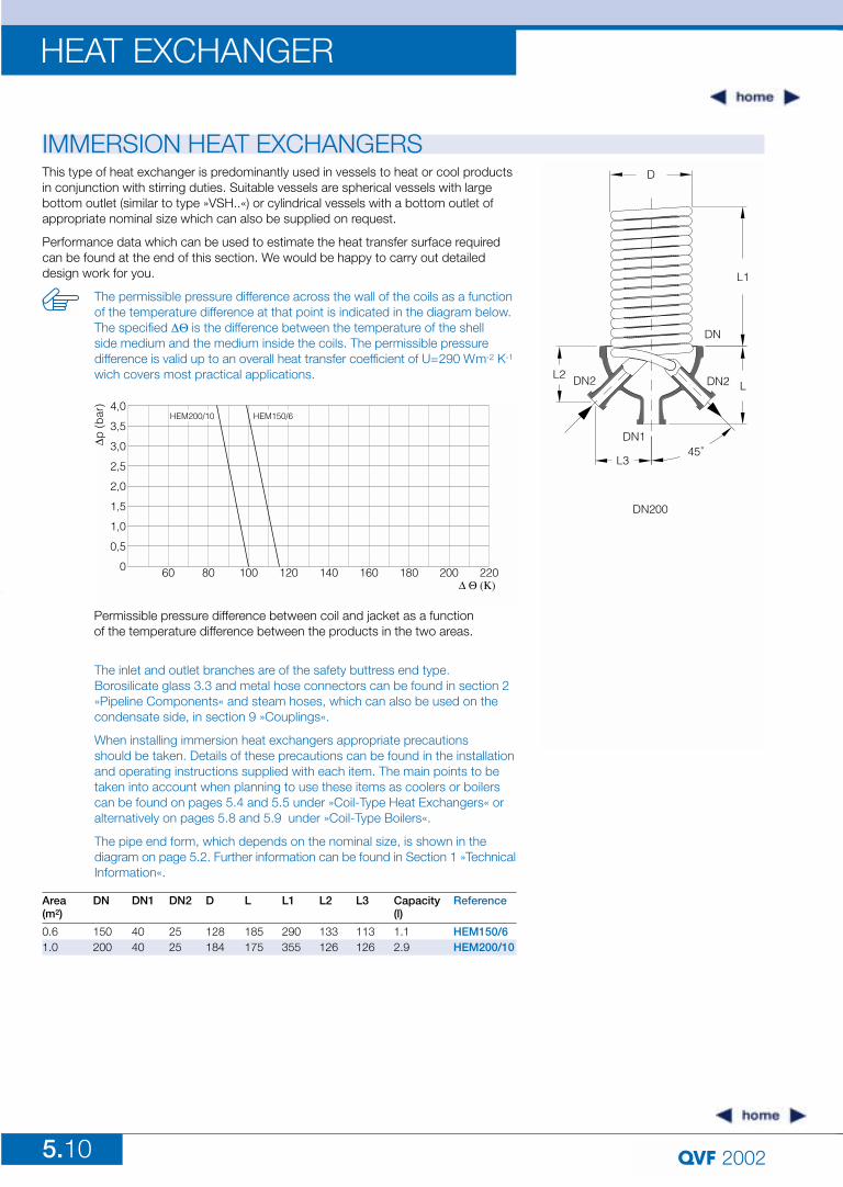
IMMERSION HEAT EXCHANGERSThis type of heat exchanger is predominantly used in vessels to heat or cool productsin conjunction with stirring duties. Suitable vessels are spherical vessels with largebottom outlet (similar to type »VSH..«) or cylindrical vessels with a bottom outlet ofappropriate nominal size which can also be supplied on request.
Performance data which can be used to estimate the heat transfer surface requiredcan be found at the end of this section. We would be happy to carry out detaileddesign work for you.
D
L1
DN
DN2 L
45˚
DN200
L3
DN1
L2 DN2
The inlet and outlet branches are of the safety buttress end type. Borosilicate glass 3.3 and metal hose connectors can be found in section 2»Pipeline Components« and steam hoses, which can also be used on thecondensate side, in section 9 »Couplings«.
When installing immersion heat exchangers appropriate precautions should be taken. Details of these precautions can be found in the installation and operating instructions supplied with each item. The main points to be taken into account when planning to use these items as coolers or boilers can be found on pages 5.4 and 5.5 under »Coil-Type Heat Exchangers« or alternatively on pages 5.8 and 5.9 under »Coil-Type Boilers«.
The pipe end form, which depends on the nominal size, is shown in the diagram on page 5.2. Further information can be found in Section 1 »TechnicalInformation«.
Permissible pressure difference between coil and jacket as a functionof the temperature difference between the products in the two areas.
DN
150200
DN1
4040
DN2
2525
D
128184
L
185175
L1
290355
L2
133126
L3
113126
Capacity(l)
1.12.9
Area (m2)
0.61.0
Reference
HEM150/6HEM200/10
The permissible pressure difference across the wall of the coils as a functionof the temperature difference at that point is indicated in the diagram below.The specified !"$is the difference between the temperature of the shell side medium and the medium inside the coils. The permissible pressure difference is valid up to an overall heat transfer coefficient of U=290 Wm-2 K-1
wich covers most practical applications.
5.11
HEAT EXCHANGER
2002
IMMERSION HEAT EXCHANGERS
For approximate calculation of evaporation performance the heat transferred in all sizes can be considered on average as 400 W/m2K with a steam pressure in the coils of 3.0 bar g. This figure declines marginally at lower pressures.
The table below shows figures calculated on this basis for the evaporation of water with an inlet temperature of 100 ºC and at atmospheric pressure (if the feed is cold, the performance of the boiler will be only about 80% of the figures quoted):
Performance data
Area(m2)
0,6
1,0
Reference
HEM150/6
HEM200/10
Steam pressure(bar g)
2323
Water evaporated(kg/h)
13,517,52028
5.12
HEAT EXCHANGER
2002
LIQUID COOLERSDN1
DN2
L
DN
DN2
L2
DN1
L1
45˚
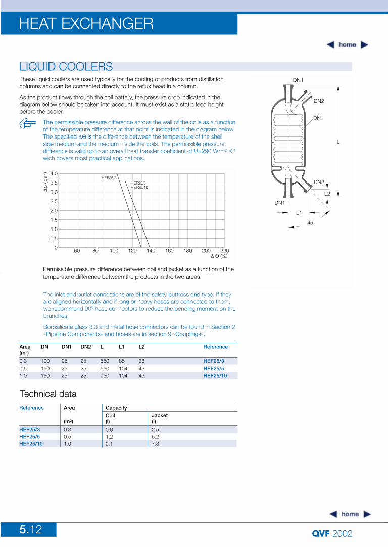
These liquid coolers are used typically for the cooling of products from distillationcolumns and can be connected directly to the reflux head in a column.
As the product flows through the coil battery, the pressure drop indicated in the diagram below should be taken into account. It must exist as a static feed heightbefore the cooler.
The inlet and outlet connections are of the safety buttress end type. If theyare aligned horizontally and if long or heavy hoses are connected to them,we recommend 90º hose connectors to reduce the bending moment on thebranches.
Borosilicate glass 3.3 and metal hose connectors can be found in Section 2»Pipeline Components« and hoses are in section 9 »Couplings«.
Permissible pressure difference between coil and jacket as a function of the temperature difference between the products in the two areas.
Technical dataArea
(m2)
0.30.51.0
Reference
HEF25/3HEF25/5HEF25/10
Coil(l)
0.61.22.1
Jacket(l)
2.55.27.3
Capacity
DN2
252525
DN
100150150
DN1
252525
L
550550750
L1
85104104
L2
384343
Area (m2)
0,30,51,0
Reference
HEF25/3HEF25/5HEF25/10
The permissible pressure difference across the wall of the coils as a functionof the temperature difference at that point is indicated in the diagram below.The specified !"$is the difference between the temperature of the shell side medium and the medium inside the coils. The permissible pressure difference is valid up to an overall heat transfer coefficient of U=290 Wm-2 K-1
wich covers most practical applications.
5.13
HEAT EXCHANGER
2002
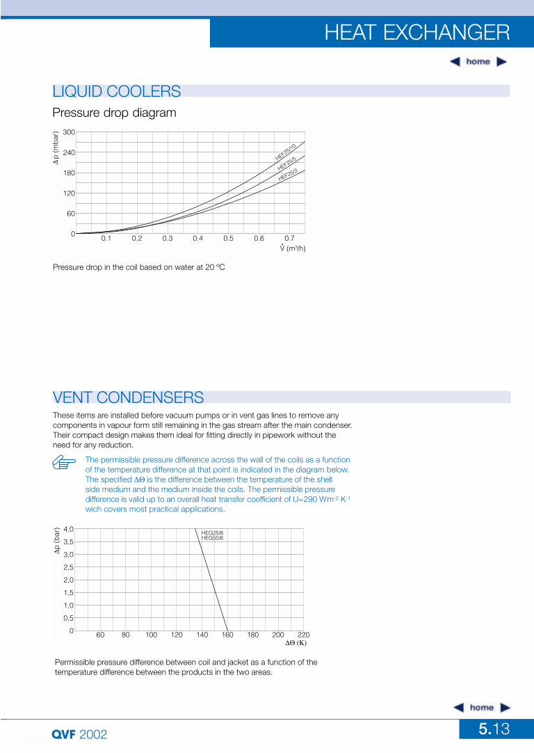
LIQUID COOLERS
Pressure drop in the coil based on water at 20 ºC
Pressure drop diagram
VENT CONDENSERSThese items are installed before vacuum pumps or in vent gas lines to remove anycomponents in vapour form still remaining in the gas stream after the main condenser.Their compact design makes them ideal for fitting directly in pipework without theneed for any reduction.
The permissible pressure difference across the wall of the coils as a functionof the temperature difference at that point is indicated in the diagram below.The specified !"$is the difference between the temperature of the shell side medium and the medium inside the coils. The permissible pressure difference is valid up to an overall heat transfer coefficient of U=290 Wm-2 K-1
wich covers most practical applications.
Permissible pressure difference between coil and jacket as a function of thetemperature difference between the products in the two areas.
5.14
HEAT EXCHANGER
2002
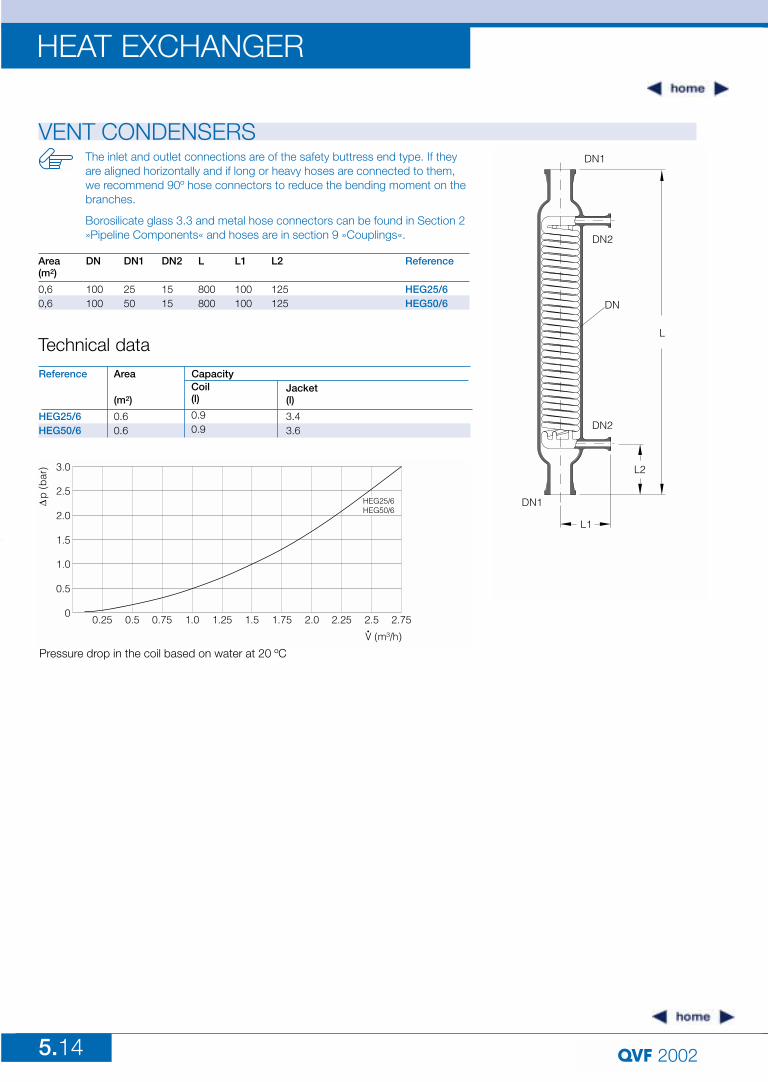
VENT CONDENSERSDN1
DN2
DN2
L2
L
DN
L1
DN1
The inlet and outlet connections are of the safety buttress end type. If theyare aligned horizontally and if long or heavy hoses are connected to them,we recommend 90º hose connectors to reduce the bending moment on thebranches.
Borosilicate glass 3.3 and metal hose connectors can be found in Section 2»Pipeline Components« and hoses are in section 9 »Couplings«.
Pressure drop in the coil based on water at 20 ºC
Technical dataArea
(m2)
0.60.6
Reference
HEG25/6HEG50/6
Coil(l)
0.90.9
Jacket(l)
3.43.6
Capacity
DN
100100
DN1
2550
DN2
1515
L
800800
L1
100100
L2
125125
Area (m2)
0,60,6
Reference
HEG25/6HEG50/6
5.15
HEAT EXCHANGER
2002
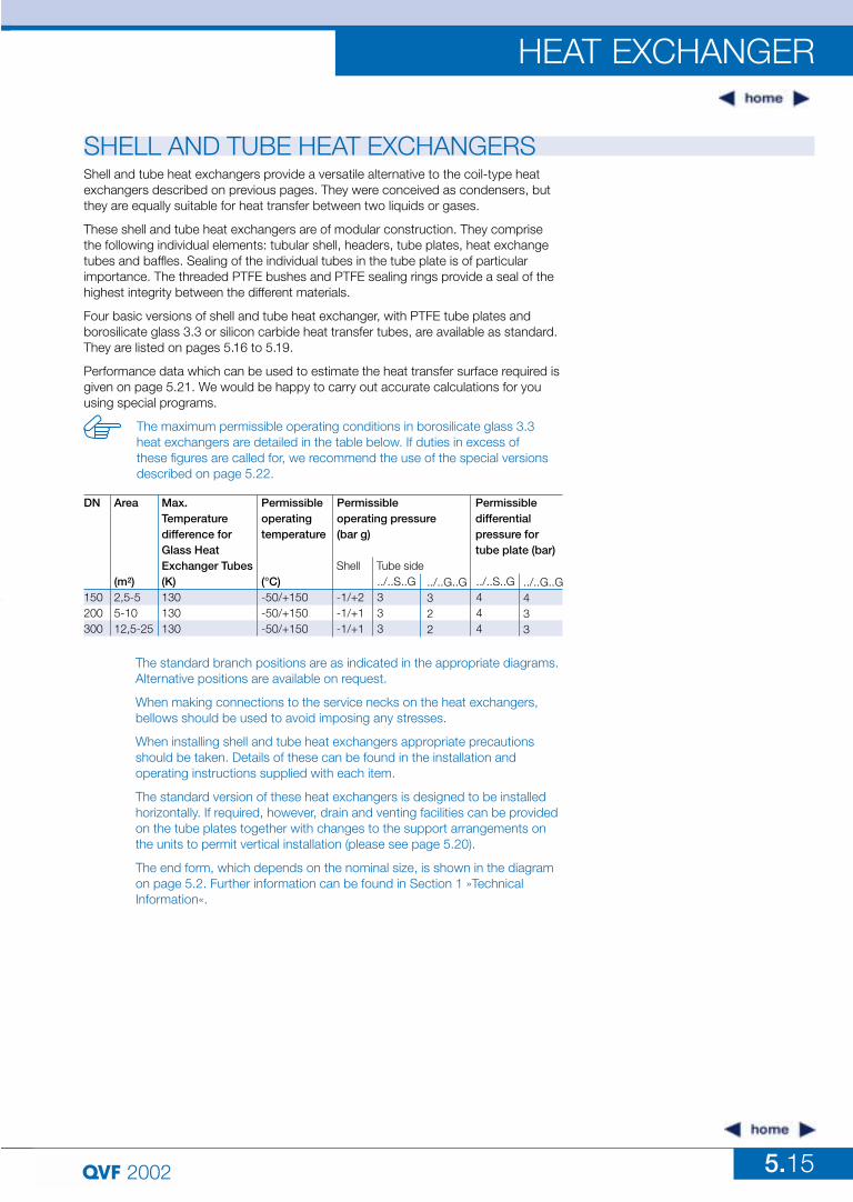
SHELL AND TUBE HEAT EXCHANGERSShell and tube heat exchangers provide a versatile alternative to the coil-type heatexchangers described on previous pages. They were conceived as condensers, butthey are equally suitable for heat transfer between two liquids or gases.
These shell and tube heat exchangers are of modular construction. They comprisethe following individual elements: tubular shell, headers, tube plates, heat exchangetubes and baffles. Sealing of the individual tubes in the tube plate is of particularimportance. The threaded PTFE bushes and PTFE sealing rings provide a seal of thehighest integrity between the different materials.
Four basic versions of shell and tube heat exchanger, with PTFE tube plates andborosilicate glass 3.3 or silicon carbide heat transfer tubes, are available as standard.They are listed on pages 5.16 to 5.19.
Performance data which can be used to estimate the heat transfer surface required isgiven on page 5.21. We would be happy to carry out accurate calculations for youusing special programs.
The maximum permissible operating conditions in borosilicate glass 3.3 heat exchangers are detailed in the table below. If duties in excess of these figures are called for, we recommend the use of the special versions described on page 5.22.
The standard branch positions are as indicated in the appropriate diagrams.Alternative positions are available on request.
When making connections to the service necks on the heat exchangers,bellows should be used to avoid imposing any stresses.
When installing shell and tube heat exchangers appropriate precautionsshould be taken. Details of these can be found in the installation and operating instructions supplied with each item.
The standard version of these heat exchangers is designed to be installedhorizontally. If required, however, drain and venting facilities can be providedon the tube plates together with changes to the support arrangements onthe units to permit vertical installation (please see page 5.20).
The end form, which depends on the nominal size, is shown in the diagramon page 5.2. Further information can be found in Section 1 »Technical Information«.
DN
150200300
Area
(m2)2,5-55-1012,5-25
Max.Temperaturedifference for Glass HeatExchanger Tubes(K)130130130
Permissibleoperatingtemperature
(°C)-50/+150-50/+150-50/+150
Permissibleoperating pressure(bar g)
Shell
-1/+2-1/+1-1/+1
Tube side../..S..G333
../..S..G444
../..G..G322
../..G..G433
Permissibledifferentialpressure fortube plate (bar)
5.16
HEAT EXCHANGER
2002
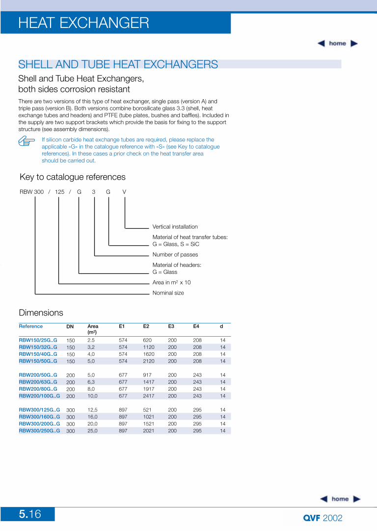
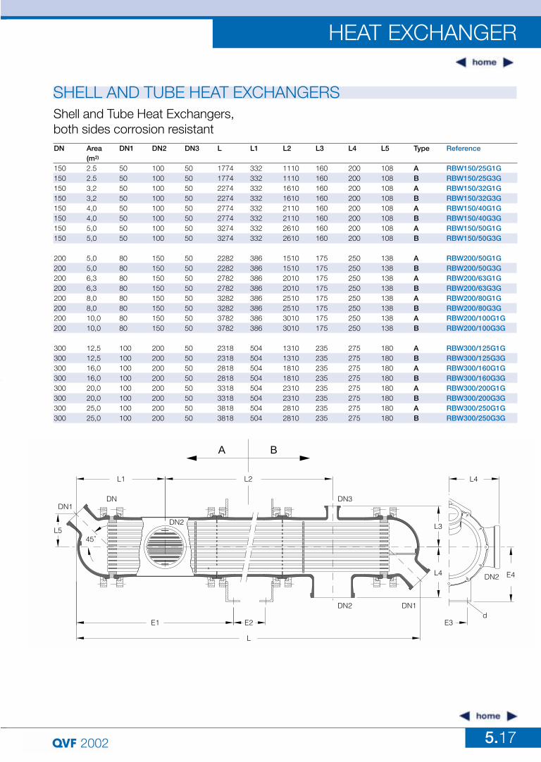
SHELL AND TUBE HEAT EXCHANGERSShell and Tube Heat Exchangers, both sides corrosion resistantThere are two versions of this type of heat exchanger, single pass (version A) and triple pass (version B). Both versions combine borosilicate glass 3.3 (shell, heatexchange tubes and headers) and PTFE (tube plates, bushes and baffles). Included inthe supply are two support brackets which provide the basis for fixing to the supportstructure (see assembly dimensions).
If silicon carbide heat exchange tubes are required, please replace the applicable »G« in the catalogue reference with »S« (see Key to cataloguereferences). In these cases a prior check on the heat transfer area should be carried out.
Key to catalogue references
RBW 300 / 125 / G 3 G V
Vertical installation
Material of heat transfer tubes:G = Glass, S = SiC
Number of passes
Material of headers:G = Glass
Area in m2 x 10
Nominal size
Reference
RBW150/25G..GRBW150/32G..GRBW150/40G..GRBW150/50G..G
RBW200/50G..GRBW200/63G..GRBW200/80G..GRBW200/100G..G
RBW300/125G..GRBW300/160G..GRBW300/200G..GRBW300/250G..G
DN
150150150150
200200200200
300300300300
Area (m2)
2.53,24,05,0
5,06,38,010,0
12,516,020,025,0
E2
620112016202120
917141719172417
521102115212021
E1
574574574574
677677677677
897897897897
E3
200200200200
200200200200
200200200200
E4
208208208208
243243243243
295295295295
d
14141414
14141414
14141414
Dimensions
5.17
HEAT EXCHANGER
2002
SHELL AND TUBE HEAT EXCHANGERS
DN Area DN1 DN2 DN3 L L1 L2 L3 L4 L5 Type Reference(m2)
150 2.5 50 100 50 1774 332 1110 160 200 108 A RBW150/25G1G150 2.5 50 100 50 1774 332 1110 160 200 108 B RBW150/25G3G150 3,2 50 100 50 2274 332 1610 160 200 108 A RBW150/32G1G150 3,2 50 100 50 2274 332 1610 160 200 108 B RBW150/32G3G150 4,0 50 100 50 2774 332 2110 160 200 108 A RBW150/40G1G150 4,0 50 100 50 2774 332 2110 160 200 108 B RBW150/40G3G150 5,0 50 100 50 3274 332 2610 160 200 108 A RBW150/50G1G150 5,0 50 100 50 3274 332 2610 160 200 108 B RBW150/50G3G
200 5,0 80 150 50 2282 386 1510 175 250 138 A RBW200/50G1G200 5,0 80 150 50 2282 386 1510 175 250 138 B RBW200/50G3G200 6,3 80 150 50 2782 386 2010 175 250 138 A RBW200/63G1G200 6,3 80 150 50 2782 386 2010 175 250 138 B RBW200/63G3G200 8,0 80 150 50 3282 386 2510 175 250 138 A RBW200/80G1G200 8,0 80 150 50 3282 386 2510 175 250 138 B RBW200/80G3G200 10,0 80 150 50 3782 386 3010 175 250 138 A RBW200/100G1G200 10,0 80 150 50 3782 386 3010 175 250 138 B RBW200/100G3G
300 12,5 100 200 50 2318 504 1310 235 275 180 A RBW300/125G1G300 12,5 100 200 50 2318 504 1310 235 275 180 B RBW300/125G3G300 16,0 100 200 50 2818 504 1810 235 275 180 A RBW300/160G1G300 16,0 100 200 50 2818 504 1810 235 275 180 B RBW300/160G3G300 20,0 100 200 50 3318 504 2310 235 275 180 A RBW300/200G1G300 20,0 100 200 50 3318 504 2310 235 275 180 B RBW300/200G3G300 25,0 100 200 50 3818 504 2810 235 275 180 A RBW300/250G1G300 25,0 100 200 50 3818 504 2810 235 275 180 B RBW300/250G3G
Shell and Tube Heat Exchangers, both sides corrosion resistant
E1 E2
L
DN2
DN3
L5
DN1
DN1DN
L1 L2
DN2 L3
L4
A B
L4
E3d
DN2 E4
45˚
5.18
HEAT EXCHANGER
2002
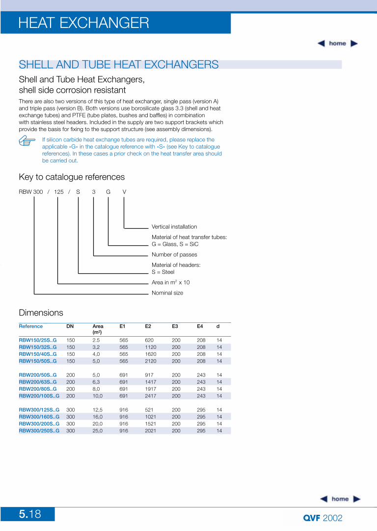
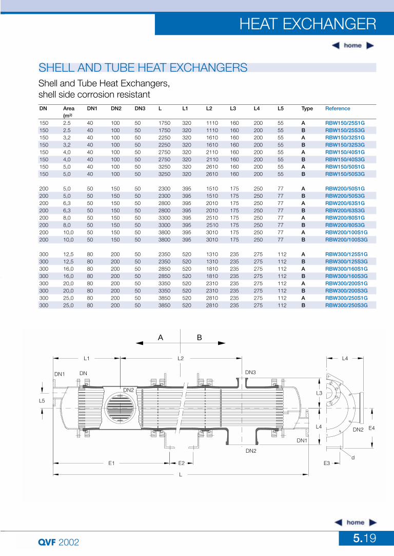
SHELL AND TUBE HEAT EXCHANGERSShell and Tube Heat Exchangers, shell side corrosion resistantThere are also two versions of this type of heat exchanger, single pass (version A) and triple pass (version B). Both versions use borosilicate glass 3.3 (shell and heatexchange tubes) and PTFE (tube plates, bushes and baffles) in combination with stainless steel headers. Included in the supply are two support brackets which provide the basis for fixing to the support structure (see assembly dimensions).
If silicon carbide heat exchange tubes are required, please replace the applicable »G« in the catalogue reference with »S« (see Key to cataloguereferences). In these cases a prior check on the heat transfer area should be carried out.
Key to catalogue references
RBW 300 / 125 / S 3 G V
Vertical installation
Material of heat transfer tubes:G = Glass, S = SiC
Number of passes
Material of headers:S = Steel
Area in m2 x 10
Nominal size
Reference
RBW150/25S..GRBW150/32S..GRBW150/40S..GRBW150/50S..G
RBW200/50S..GRBW200/63S..GRBW200/80S..GRBW200/100S..G
RBW300/125S..GRBW300/160S..GRBW300/200S..GRBW300/250S..G
DN
150150150150
200200200200
300300300300
Area(m2)
2.53,24,05,0
5,06,38,010,0
12,516,020,025,0
E2
620112016202120
917141719172417
521102115212021
E1
565565565565
691691691691
916916916916
E3
200200200200
200200200200
200200200200
E4
208208208208
243243243243
295295295295
d
14141414
14141414
14141414
Dimensions
5.19
HEAT EXCHANGER
2002
SHELL AND TUBE HEAT EXCHANGERS
DN Area DN1 DN2 DN3 L L1 L2 L3 L4 L5 Type Reference(m2)
150 2.5 40 100 50 1750 320 1110 160 200 55 A RBW150/25S1G150 2.5 40 100 50 1750 320 1110 160 200 55 B RBW150/25S3G150 3,2 40 100 50 2250 320 1610 160 200 55 A RBW150/32S1G150 3,2 40 100 50 2250 320 1610 160 200 55 B RBW150/32S3G150 4,0 40 100 50 2750 320 2110 160 200 55 A RBW150/40S1G150 4,0 40 100 50 2750 320 2110 160 200 55 B RBW150/40S3G150 5,0 40 100 50 3250 320 2610 160 200 55 A RBW150/50S1G150 5,0 40 100 50 3250 320 2610 160 200 55 B RBW150/50S3G
200 5,0 50 150 50 2300 395 1510 175 250 77 A RBW200/50S1G200 5,0 50 150 50 2300 395 1510 175 250 77 B RBW200/50S3G200 6,3 50 150 50 2800 395 2010 175 250 77 A RBW200/63S1G200 6,3 50 150 50 2800 395 2010 175 250 77 B RBW200/63S3G200 8,0 50 150 50 3300 395 2510 175 250 77 A RBW200/80S1G200 8,0 50 150 50 3300 395 2510 175 250 77 B RBW200/80S3G200 10,0 50 150 50 3800 395 3010 175 250 77 A RBW200/100S1G200 10,0 50 150 50 3800 395 3010 175 250 77 B RBW200/100S3G
300 12,5 80 200 50 2350 520 1310 235 275 112 A RBW300/125S1G300 12,5 80 200 50 2350 520 1310 235 275 112 B RBW300/125S3G300 16,0 80 200 50 2850 520 1810 235 275 112 A RBW300/160S1G300 16,0 80 200 50 2850 520 1810 235 275 112 B RBW300/160S3G300 20,0 80 200 50 3350 520 2310 235 275 112 A RBW300/200S1G300 20,0 80 200 50 3350 520 2310 235 275 112 B RBW300/200S3G300 25,0 80 200 50 3850 520 2810 235 275 112 A RBW300/250S1G300 25,0 80 200 50 3850 520 2810 235 275 112 B RBW300/250S3G
Shell and Tube Heat Exchangers, shell side corrosion resistant
L5
L1
DN1 DN
DN2
E1 E2
L
L2
A B
DN3
DN2
DN1
L4
L3
L4
E4DN2
E3d
5.20
HEAT EXCHANGER
2002
SHELL AND TUBE HEAT EXCHANGERS
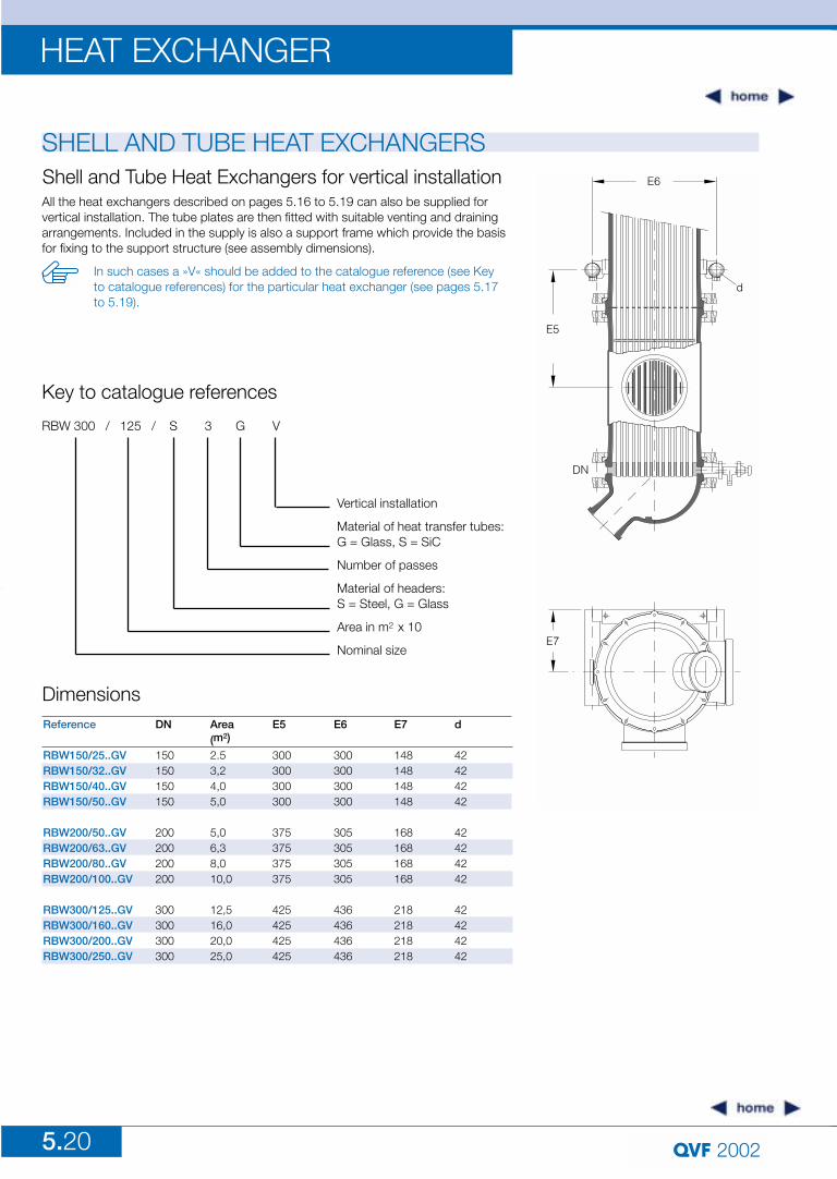
Reference
RBW150/25..GVRBW150/32..GVRBW150/40..GVRBW150/50..GV
RBW200/50..GVRBW200/63..GVRBW200/80..GVRBW200/100..GV
RBW300/125..GVRBW300/160..GVRBW300/200..GVRBW300/250..GV
DN
150150150150
200200200200
300300300300
Area(m2)
2.53,24,05,0
5,06,38,010,0
12,516,020,025,0
E6
300300300300
305305305305
436436436436
E5
300300300300
375375375375
425425425425
d
42424242
42424242
42424242
E7
148148148148
168168168168
218218218218
Dimensions
Shell and Tube Heat Exchangers for vertical installationAll the heat exchangers described on pages 5.16 to 5.19 can also be supplied forvertical installation. The tube plates are then fitted with suitable venting and drainingarrangements. Included in the supply is also a support frame which provide the basisfor fixing to the support structure (see assembly dimensions).
In such cases a »V« should be added to the catalogue reference (see Key to catalogue references) for the particular heat exchanger (see pages 5.17to 5.19).
E6
E5
d
DN
E7
Key to catalogue references
RBW 300 / 125 / S 3 G V
Vertical installation
Material of heat transfer tubes:G = Glass, S = SiC
Number of passes
Material of headers:S = Steel, G = Glass
Area in m2 x 10
Nominal size
5.21
HEAT EXCHANGER
2002
SHELL AND TUBE HEAT EXCHANGERS
Reference
RBW150/25..1..RBW150/32..1..RBW150/40..1..RBW150/50..1..
RBW200/50..1..RBW200/63..1..RBW200/80..1..RBW200/100..1..
RBW300/125..1..RBW300/160..1..RBW300/200..1..RBW300/250..1..
RBW150/25..3..RBW150/32..3..RBW150/40..3..RBW150/50..3..
RBW200/50..3..RBW200/63..3..RBW200/80..3..RBW200/100..3..
RBW300/125..3..RBW300/160..3..RBW300/200..3..RBW300/250..3..
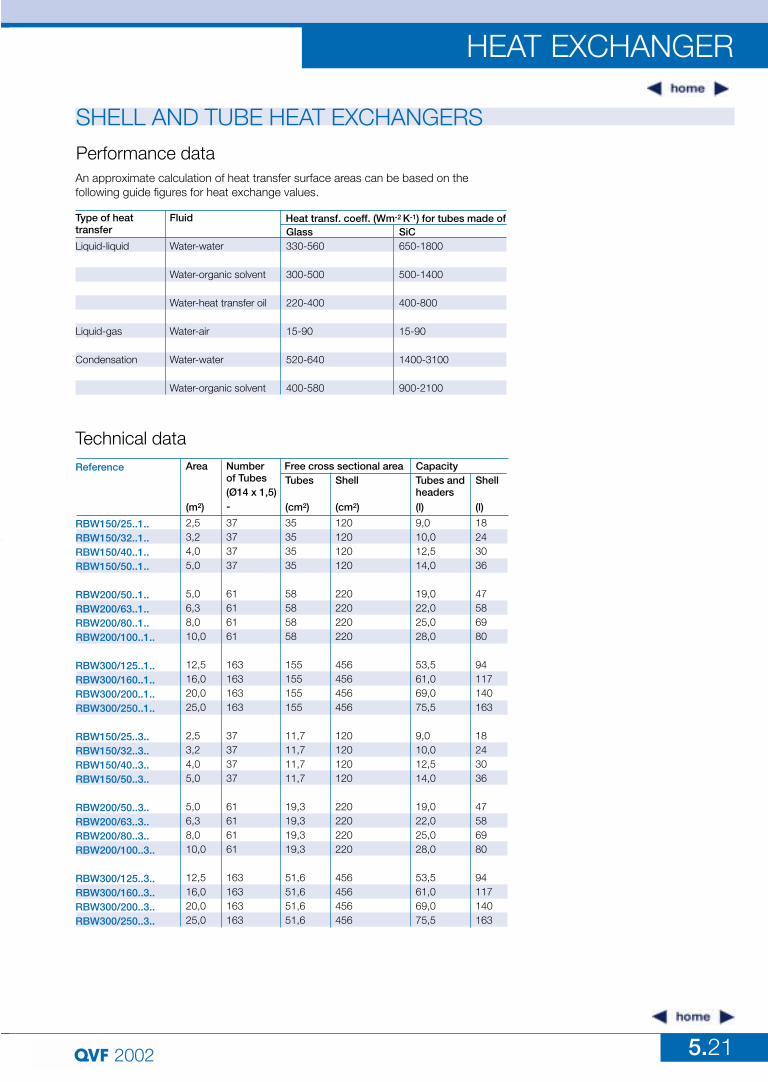
Type of heat transfer
Liquid-liquid
Liquid-gas
Condensation
Fluid
Water-water
Water-organic solvent
Water-heat transfer oil
Water-air
Water-water
Water-organic solvent
Performance data
Technical data
Heat transf. coeff. (Wm-2 K-1) for tubes made of
An approximate calculation of heat transfer surface areas can be based on the following guide figures for heat exchange values.
Area
(m2)
2,53,24,05,0
5,06,38,010,0
12,516,020,025,0
2,53,24,05,0
5,06,38,010,0
12,516,020,025,0
Numberof Tubes(Ø14 x 1,5)-
37373737
61616161
163163163163
37373737
61616161
163163163163
Tubes
(cm2)
35353535
58585858
155155155155
11,711,711,711,7
19,319,319,319,3
51,651,651,651,6
Shell
(cm2)
120120120120
220220220220
456456456456
120120120120
220220220220
456456456456
Tubes andheaders(l)
9,010,012,514,0
19,022,025,028,0
53,561,069,075,5
9,010,012,514,0
19,022,025,028,0
53,561,069,075,5
Shell
(l)
18243036
47586980
94117140163
18243036
47586980
94117140163
Free cross sectional area Capacity
SiC650-1800
500-1400
400-800
15-90
1400-3100
900-2100
Glass330-560
300-500
220-400
15-90
520-640
400-580
5.22
HEAT EXCHANGER
2002
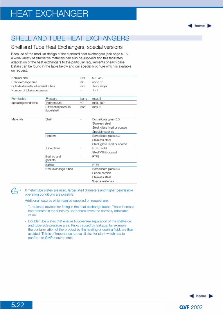
SHELL AND TUBE HEAT EXCHANGERSShell and Tube Heat Exchangers, special versionsBecause of the modular design of the standard heat exchangers (see page 5.15), a wide variety of alternative materials can also be supplied and this facilitates adaptation of the heat exchangers to the particular requirements of each case. Details can be found in the table below and our special brochure which is available on request.
If metal tube plates are used, larger shell diameters and higher permissibleoperating conditions are possible.
Additional features which can be supplied on request are:
- Turbulence devices for fitting in the heat exchange tubes. These increase heat transfer in the tubes by up to three times the normally attainable value.
- Double tube plates that ensure trouble-free separation of the shell-side and tube-side pressure area. Risks caused by leakage, for example the contamination of the product by the heating or cooling fluid, are thus avoided. This is of importance above all else for plant which has to conform to GMP requirements.
Nominal size DN 50 - 450Heat exchange area m2 up to 60Outside diameter of internal tubes mm 14 or largerNumber of tube side passes - 1 - 4
Permissible Pressure bar g max. 5operating conditions Temperature ºC max. 180
Differential pressure bar max. 6(tube/shell)
Materials Shell - Borosilicate glass 3.3Stainless steel Steel, glass lined or coatedSpecial materials
Headers - Borosilicate glass 3.3Stainless steel Steel, glass lined or coated
Tube plates - PTFE, solidSteel/PTFE-coated
Bushes and - PTFEgaskets
Baffles - PTFEHeat exchange tubes - Borosilicate glass 3.3
Silicon carbideStainless steelSpecial materials
5.23
HEAT EXCHANGER
2002
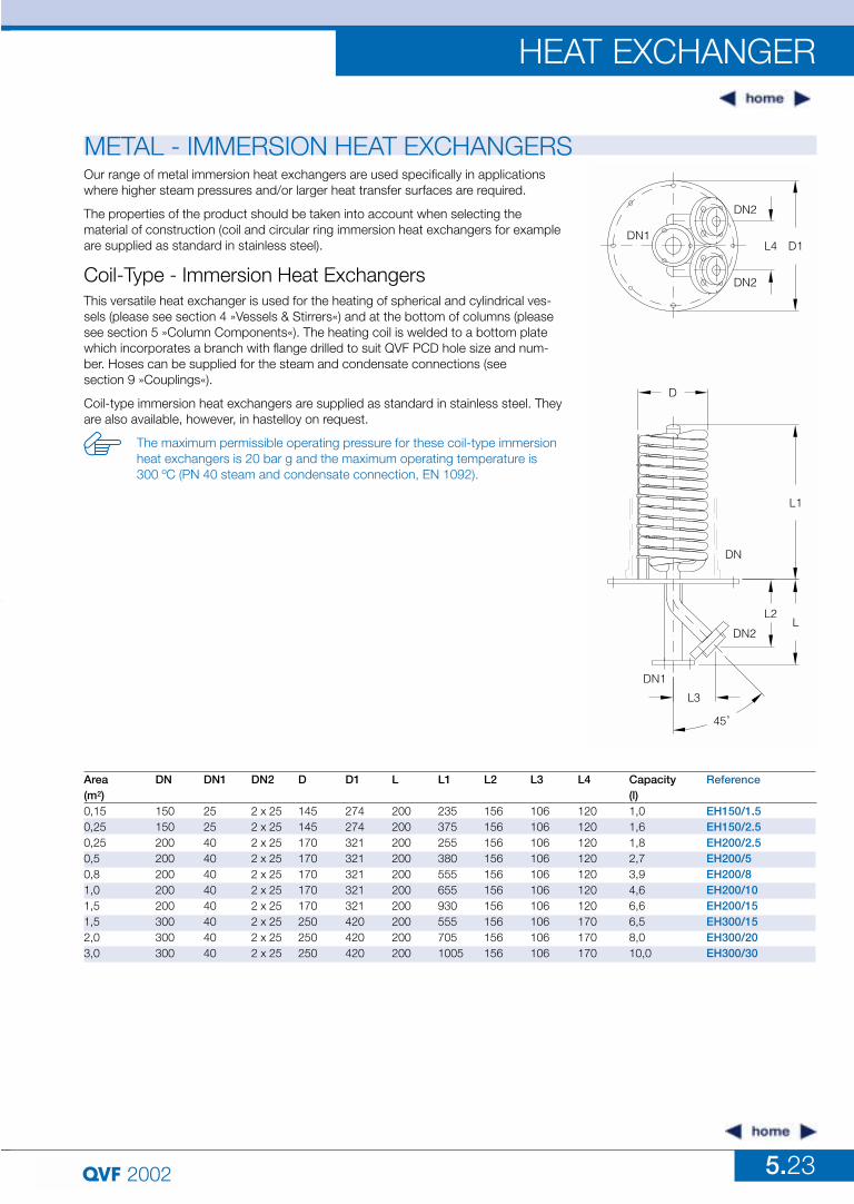
METAL - IMMERSION HEAT EXCHANGERS
Coil-Type - Immersion Heat Exchangers
Our range of metal immersion heat exchangers are used specifically in applicationswhere higher steam pressures and/or larger heat transfer surfaces are required.
The properties of the product should be taken into account when selecting the material of construction (coil and circular ring immersion heat exchangers for exampleare supplied as standard in stainless steel).
This versatile heat exchanger is used for the heating of spherical and cylindrical ves-sels (please see section 4 »Vessels & Stirrers«) and at the bottom of columns (pleasesee section 5 »Column Components«). The heating coil is welded to a bottom platewhich incorporates a branch with flange drilled to suit QVF PCD hole size and num-ber. Hoses can be supplied for the steam and condensate connections (see section 9 »Couplings«).
Coil-type immersion heat exchangers are supplied as standard in stainless steel. Theyare also available, however, in hastelloy on request.
The maximum permissible operating pressure for these coil-type immersionheat exchangers is 20 bar g and the maximum operating temperature is 300 ºC (PN 40 steam and condensate connection, EN 1092).
DN1
DN2
DN2
L4 D1
D
L1
DN
LL2
DN2
DN1
L3
45˚
Reference
EH150/1.5EH150/2.5EH200/2.5EH200/5EH200/8EH200/10EH200/15EH300/15EH300/20EH300/30
DN
150150200200200200200300300300
DN1
25254040404040404040
Area(m2)0,150,250,250,50,81,01,51,52,03,0
D
145145170170170170170250250250
DN2
2 x 252 x 252 x 252 x 252 x 252 x 252 x 252 x 252 x 252 x 25
D1
274274321321321321321420420420
L2
156156156156156156156156156156
L1
2353752553805556559305557051005
L
200200200200200200200200200200
L4
120120120120120120120170170170
Capacity(l)1,01,61,82,73,94,66,66,58,010,0
L3
106106106106106106106106106106
5.24
HEAT EXCHANGER
2002
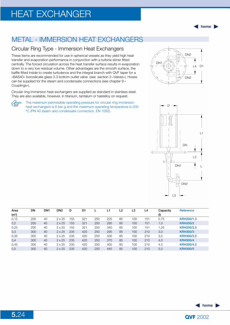
METAL - IMMERSION HEAT EXCHANGERSCircular Ring Type - Immersion Heat ExchangersThese items are recommended for use in spherical vessels as they yield high heattransfer and evaporation performance in conjunction with a turbine stirrer fittedcentrally. The forced circulation across the heat transfer surface results in evaporationdown to a very low residual volume. Other advantages are the smooth surface, thebaffle fitted inside to create turbulence and the integral branch with QVF taper for a»BAS40« borosilicate glass 3.3 bottom outlet valve (see section 3 »Valves«). Hosescan be supplied for the steam and condensate connections (see chapter 9 »Couplings«).
Circular ring immersion heat exchangers are supplied as standard in stainless steel.They are also available, however, in titanium, tantalum or hastelloy on request.
The maximum permissible operating pressure for circular ring immersionheat exchangers is 6 bar g and the maximum operating temperature is 200ºC (PN 40 steam and condensate connection, EN 1092).
DN1
DN2
L4 D1
DN2
D
L1
DN
L3
DN2
DN1
L2
L
Reference
KRH200/1.5KRH200/2KRH200/2.5KRH300/3KRH300/3.5KRH300/4KRH300/4.5KRH300/5
DN
200200200300300300300300
DN1
4040404040404040
Area(m2)0,150,20,250,30,350,40,450,5
D
155155155235235235235235
DN2
2 x 252 x 252 x 252 x 252 x 252 x 252 x 252 x 25
D1
321321321420420420420420
L2
8585858585858585
L1
225285340295330370405445
L
250250250250250250250250
L4
151151151210210210210210
Capacity(l)0,751,01,253,03,54,04,55,0
L3
100100100100100100100100
5.25
HEAT EXCHANGER
2002
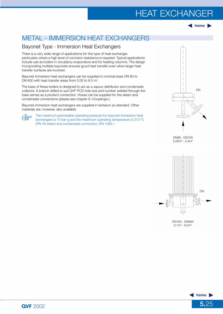
METAL - IMMERSION HEAT EXCHANGERSBayonet Type - Immersion Heat ExchangersThere is a very wide range of applications for this type of heat exchanger, particularly where a high level of corrosion resistance is required. Typical applicationsinclude use as boilers in circulatory evaporators and for heating columns. The designincorporating multiple bayonets ensures good heat transfer even when larger heattransfer surfaces are involved.
Bayonet immersion heat exchangers can be supplied in nominal sizes DN 80 to DN 600 with heat transfer areas from 0.05 to 8.5 m2.
The base of these boilers is designed to act as a vapour distributor and condensatecollector. A branch drilled to suit QVF PCD hole size and number welded through thebase serves as a product connection. Hoses can be supplied for the steam and condensate connections (please see chapter 9 »Couplings«).
Bayonet immersion heat exchangers are supplied in tantalum as standard. Othermaterials are, however, also available.
The maximum permissible operating pressure for bayonet immersion heatexchangers is 10 bar g and the maximum operating temperature is 210 ºC(PN 40 steam and condensate connection, EN 1092 ).
DN
DN80 - DN1000,05m² - 0,4m²
DN
DN150 - DN6000,1m² - 8,5m²