5 motorized - amazon simple storage service · ratus. check voltage availability. contact an...
TRANSCRIPT
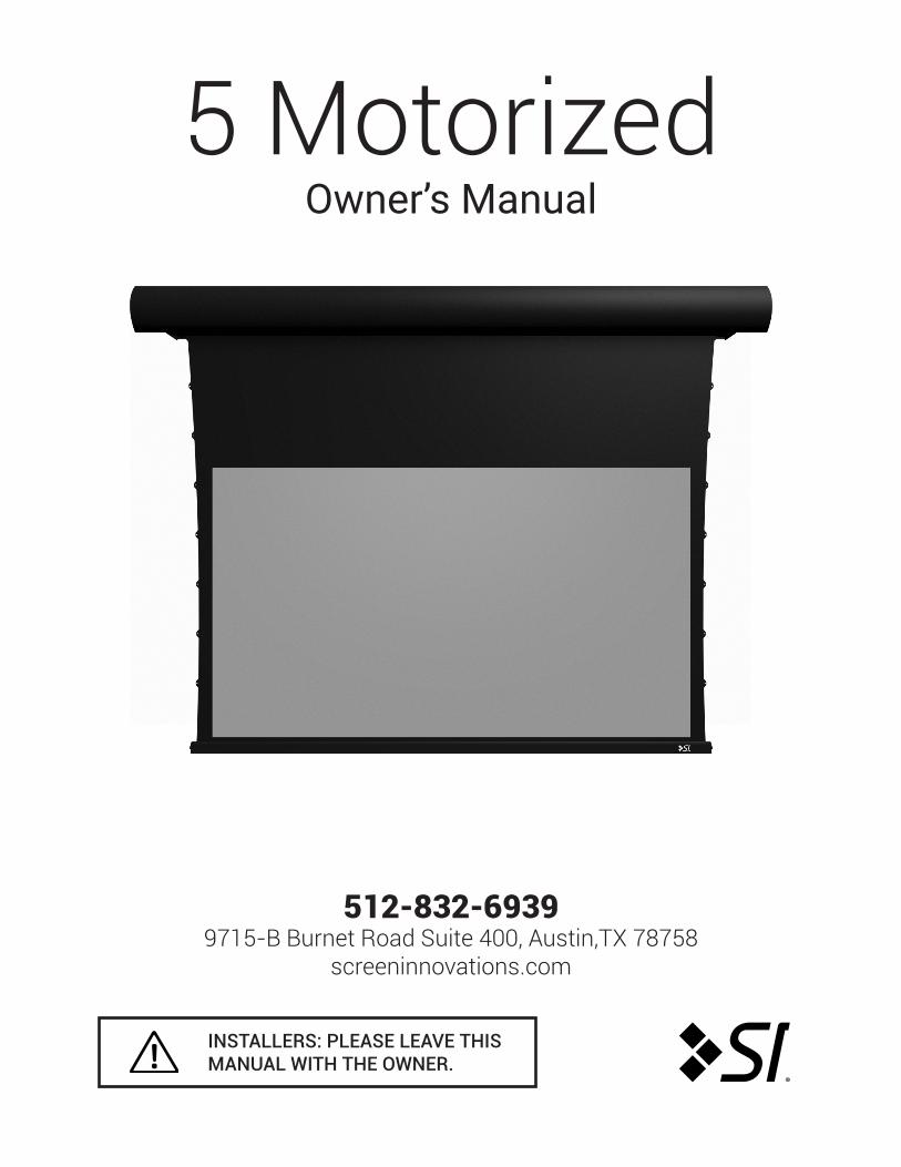
5 MotorizedOwner’s Manual
®
INSTALLERS: PLEASE LEAVE THIS MANUAL WITH THE OWNER.
512-832-69399715-B Burnet Road Suite 400, Austin,TX 78758
screeninnovations.com

Screen Innovations warrants its products, to the original purchaser only, to be free from defects in materials and workmanship for a period of one (1) year from the date of purchase by the original purchaser provided they are properly operated according to Screen Innovations’ instructions and are not damaged due to improper handling or treatment after shipment from the factory.
This warranty does not apply to equipment showing evidence of misuse, abuse, or accidental damage, or which has been tampered with or repaired by a person other than authorized Screen Innovations personnel. Screen Innovations’ sole obligation under this warranty shall be to repair or to replace (at Screen Innovations’ option) the defective part of the merchandise. Returns for service should be made to your Screen Innovations’ dealer. If it is necessary for the dealer to return the screen or part to Screen Innovations, transportation expenses to and from Screen Innovations are payable by the purchaser and Screen Innovations is not responsible for damage in shipment. To protect yourself against damage or loss in transit, insure the product and prepay all transportation expenses.
THIS WARRANTY IS IN LIEU OF ALL OTHER WARRANTIES, EXPRESS OR IMPLIED, INCLUDING WARRANTIES AS TO FITNESS FOR USE AND MERCHANT ABILITY. Any implied warranties of fitness for use, or merchantability, that may be mandated by statute or rule of law are limited to the one (1) year warranty period. This warranty gives you specific legal rights, and you may also have other rights, which vary from state-to-state. NO LIABILITY IS ASSUMED FOR EXPENSES OR DAMAGES RESULTING FROM INTERRUPTION IN OPERATION OF EQUIPMENT, OR FOR INCIDENTAL, DIRECT, OR CONSEQUENTIAL DAMAGES OF ANY NATURE.
In the event that there is a defect in materials or workmanship of a Screen Innovations product, you may contact our Sales Partners at 9715-B Burnet Road Suite 400, Austin, TX 78758, (512) 832-6939.
IMPORTANT: THIS WARRANTY SHALL NOT BE VALID AND SCREEN INNOVATIONS SHALL NOT BE BOUND BY THIS WARRANTY IF THE PRODUCT IS NOT OPERATED IN ACCORDANCE WITH SCREEN INNOVATIONS’ WRITTEN INSTRUCTIONS.
Keep your sales receipt to prove the date of purchase and your original ownership.
LIMITED ONE YEAR WARRANTYON SCREEN INNOVATIONS PRODUCTS
APPLY S/NSTICKER HERE
0410185M 3
5 MOTORIZED
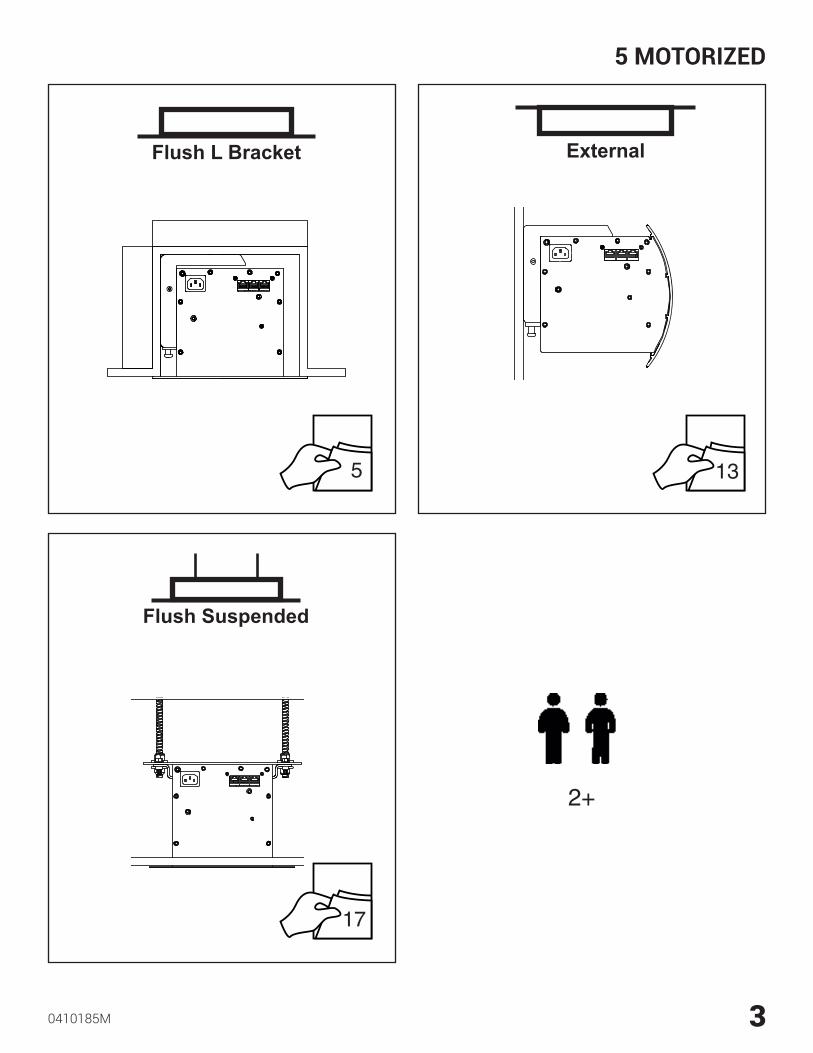
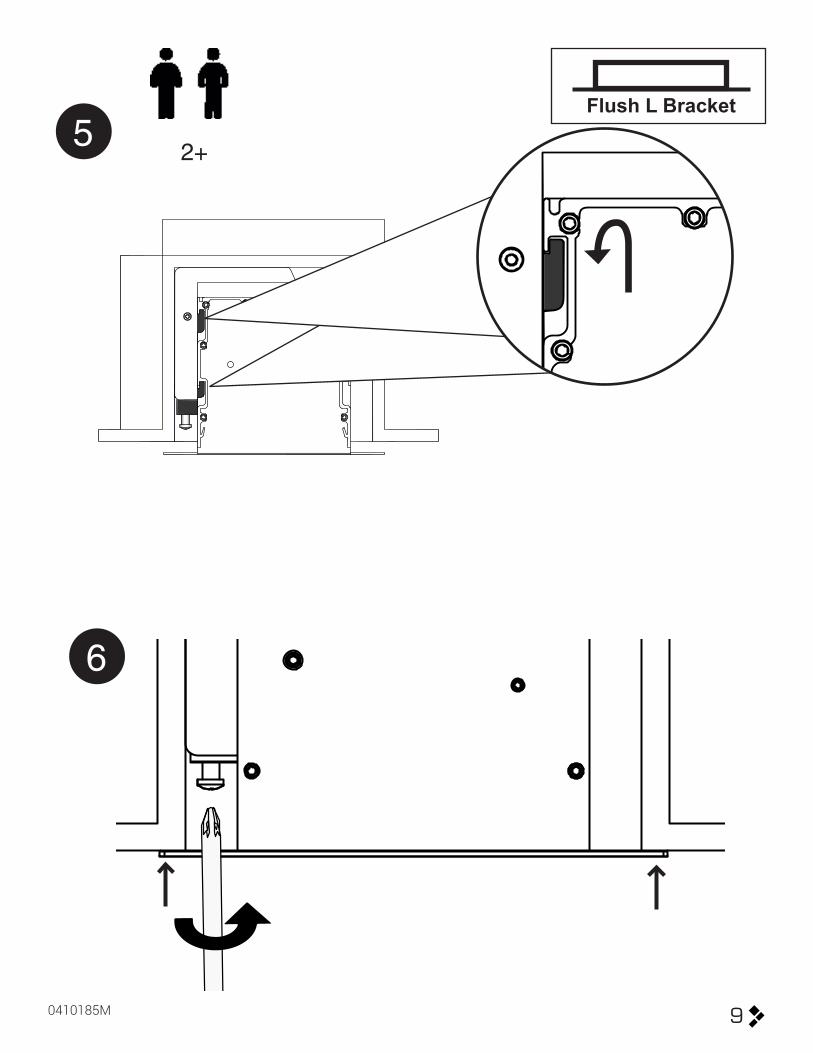
5
17
13
2+
Flush L Bracket External
Flush Suspended

4
Flush L Bracket
?
6’’ x 12’’(15.24 cm X 30.48)
It is highly recommended to provide a 6’’ x 12’’ access panel at the left end of the case and/or make sure the left end of the case can be accessed from inside the ceiling or attic.
5
Flush L Bracket
0410185M
1X
1X
1X
2X1X1X
1X 1X 1X 1X
1X
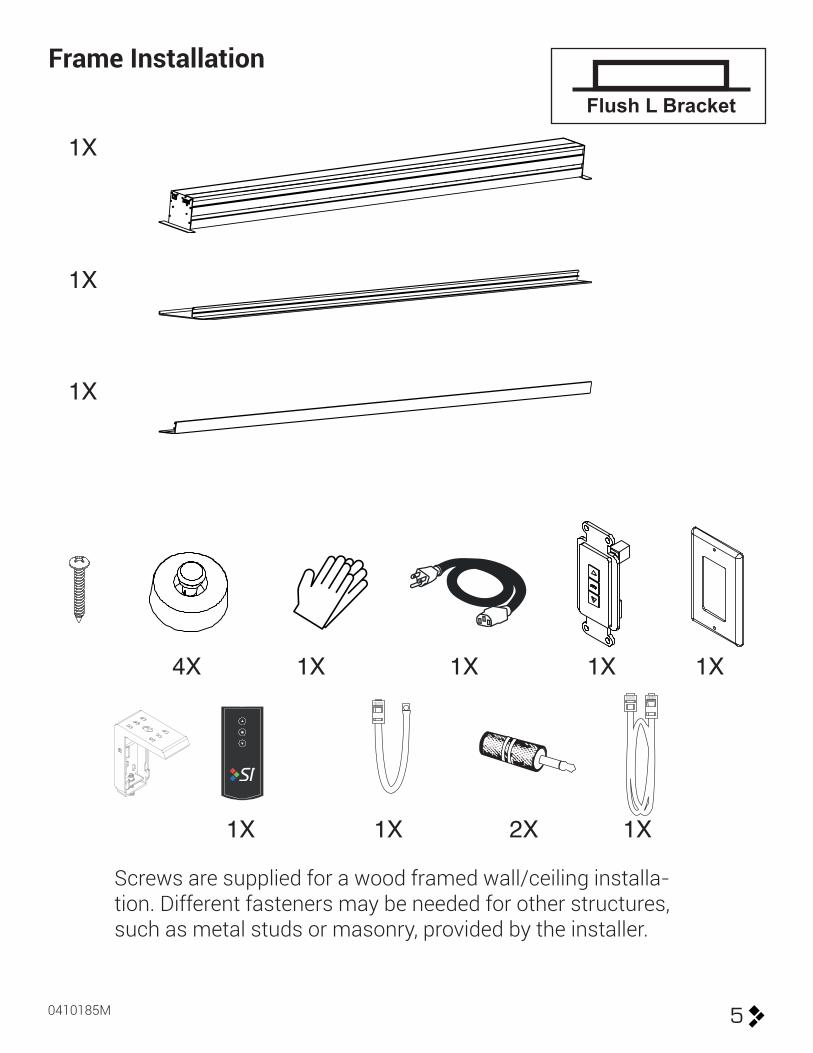
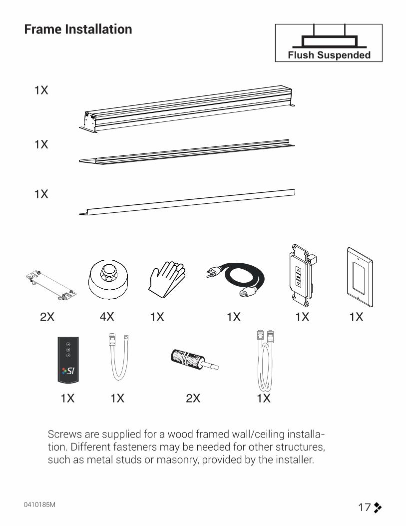
Frame Installation
Screws are supplied for a wood framed wall/ceiling installa-tion. Different fasteners may be needed for other structures, such as metal studs or masonry, provided by the installer.
4X

6
Flush L Bracket1
2
= F
Y =
in/cm
in/cm
FY
1 3/4”
(4.5 cm)
Y W
ZW
1 3/4” 1/4”
1/8”
(4.5 cm)(0.635 cm)
(0.635 cm)
F Z
+
+
=
=
Case Opening

7
Flush L Bracket
0410185M
A A7” - 2”
(17.8 cm - 5 cm)7” - 2”
(17.8 cm - 5 cm)
3
200 lbs (90gk)
Z
Ceiling
W
7 1/4”(18.4 cm)
(18.7 cm)
TO
7 3/8”

8
Flush L Bracket4
27
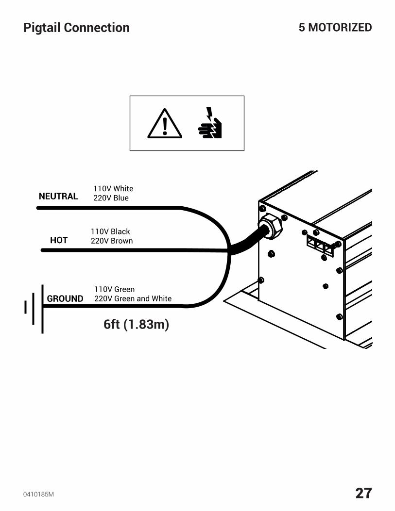
NEUTRAL 110V White220V Blue
HOT
GROUND
110V Black220V Brown
110V Green220V Green and White
A B
If there is not an access panel at the left end of the case in the ceiling, or access from above via the ceiling or attic; then you must make sure to make all power and control connections before proceeding.
9
Flush L Bracket
0410185M
2+5
6

10
Flush L Bracket7
8

11
Flush L Bracket
0410185M
9
10
12
Flush L Bracket11
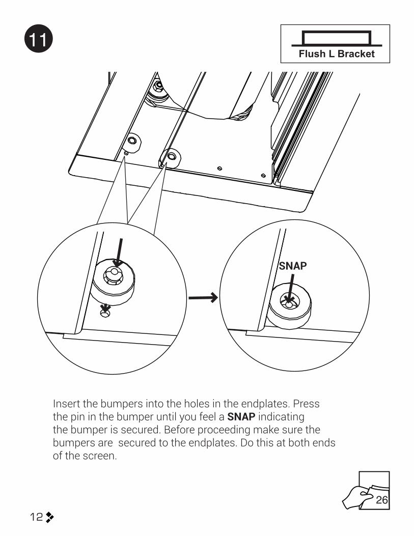
Insert the bumpers into the holes in the endplates. Press the pin in the bumper until you feel a SNAP indicating the bumper is secured. Before proceeding make sure the bumpers are secured to the endplates. Do this at both ends of the screen.
SNAP
26

13
External
0410185M
1X
1X
1X
2X1X1X
1X 1X 1X 1X
1X
PARTS LIST
Screws are supplied for a wood framed wall/ceiling installa-tion. Different fasteners may be needed for other structures, such as metal studs or masonry, provided by the installer.
14
External
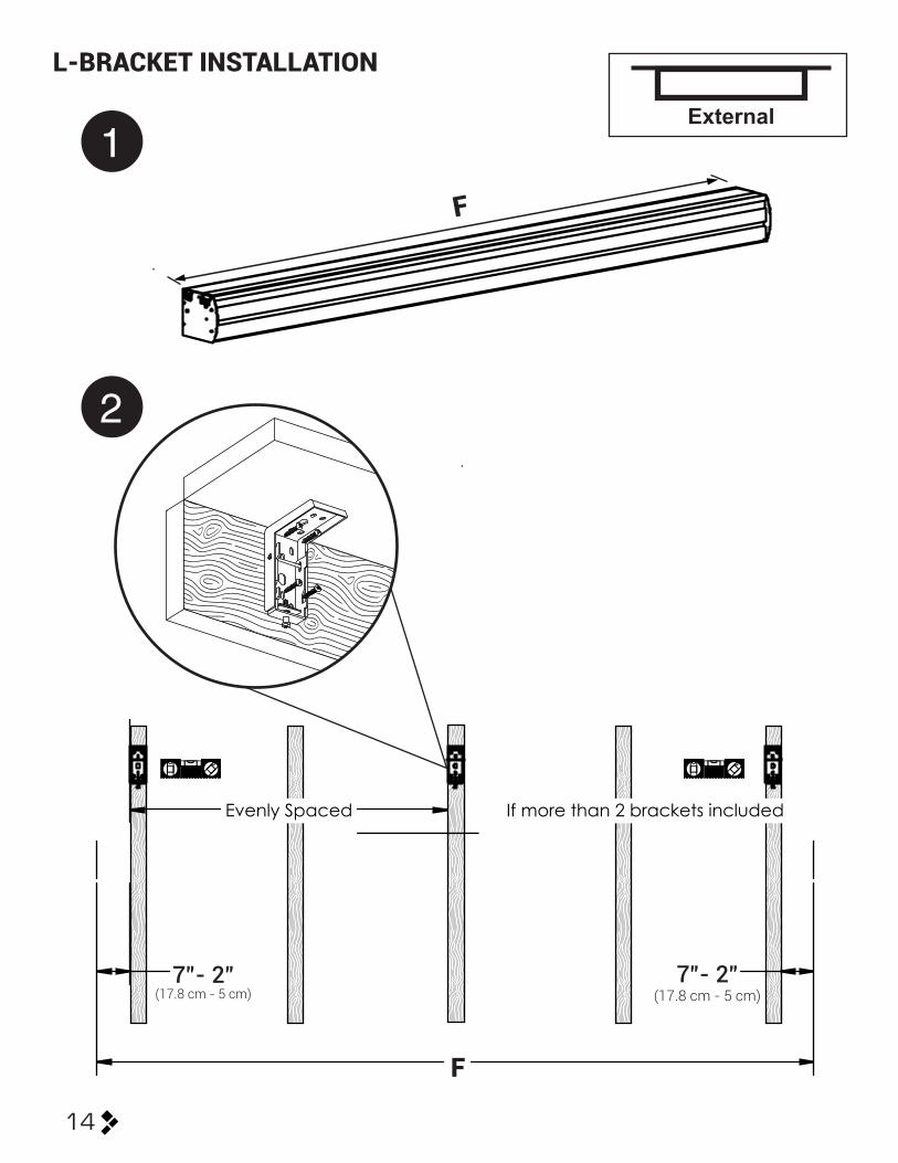
L-BRACKET INSTALLATION
1
2
Evenly Spaced If more than 2 brackets included
F
F
7”- 2”(17.8 cm - 5 cm)
7”- 2”(17.8 cm - 5 cm)
15
External
0410185M
4
3
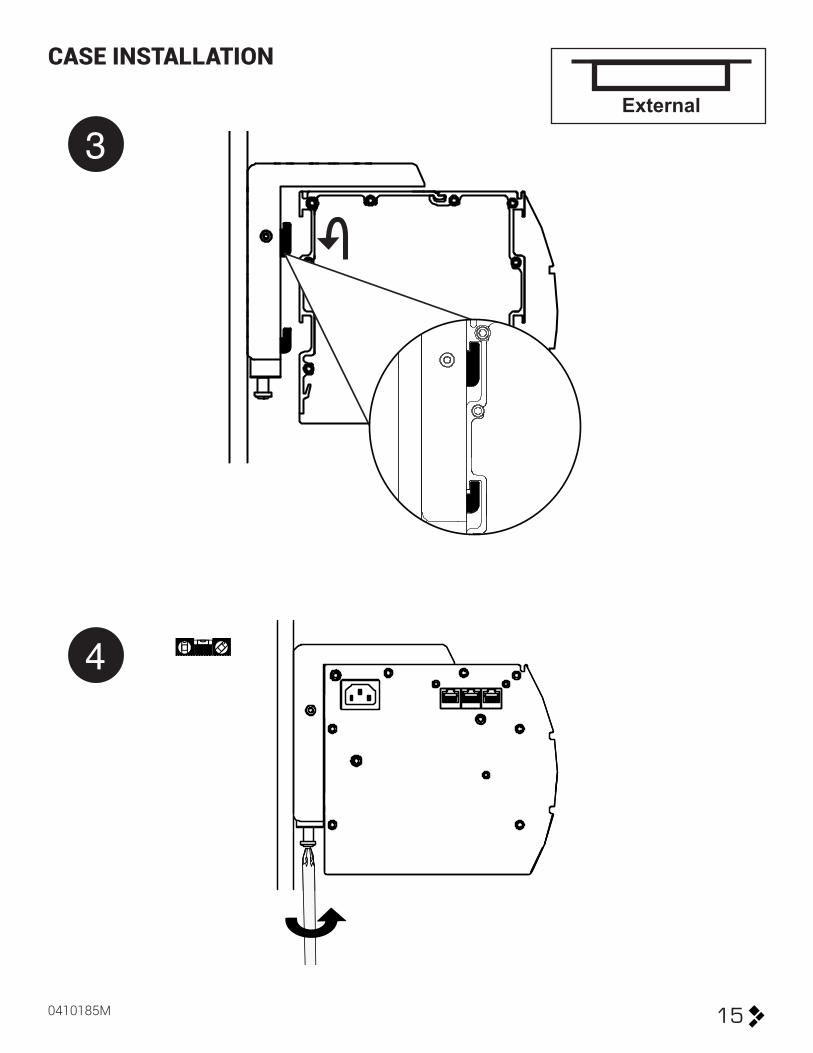
CASE INSTALLATION

16
External
5
6
26
TRIM INSTALLATION
17
Flush Suspended
0410185M
1X
1X
1X
2X1X1X
1X2X 1X 1X 1X
1X
Frame Installation
Screws are supplied for a wood framed wall/ceiling installa-tion. Different fasteners may be needed for other structures, such as metal studs or masonry, provided by the installer.
4X

18
Flush Suspended
?
Threaded Rod 3/8’’ Minimum Nut Washer Washer Nut
Parts to be supplied by installer
It is highly recommended to provide a 6’’ x 12’’ access panel at the left end of the case and/or make sure the left end of the case can be accessed from inside the ceiling or attic.
6’’ x 12’’(15.24 cm X 30.48)
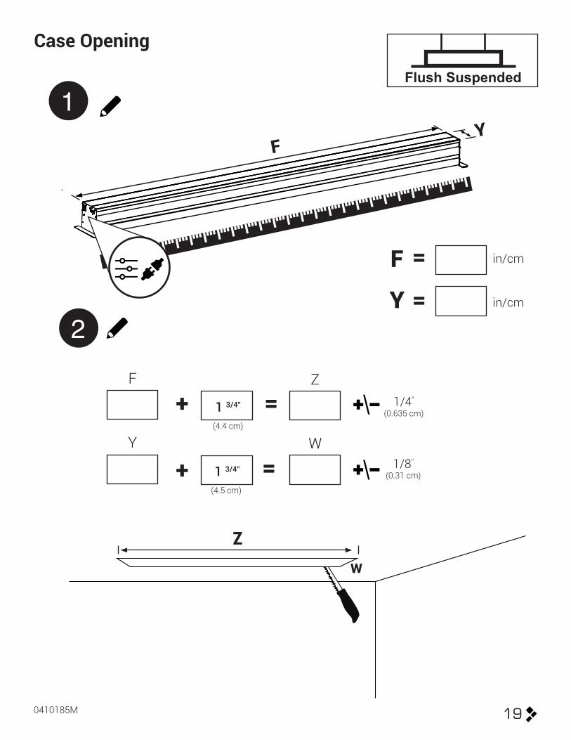
19
Flush Suspended
0410185M
1
2
= F
Y =
in/cm
in/cm
FY
1 3/4”
(4.5 cm)
Y W
ZW
1 3/4” 1/4”
1/8”
(4.4 cm)(0.635 cm)
(0.31 cm)
F Z
+
+
=
=
Case Opening

20
Flush Suspended3
4
Stuctural Member
Ceiling
4” - 12”(17.8 cm - 5 cm)
4” - 12”(17.8 cm - 5 cm)
Z
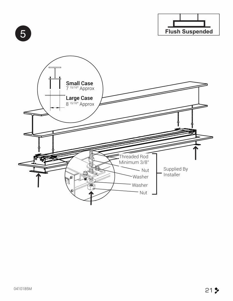
21
Flush Suspended
0410185M
5
Nut
Threaded RodMinimum 3/8’’
Nut
Washer
Washer
Supplied By Installer
Small Case7 15/16'' Approx
Large Case8 15/16'' Approx

5 MOTORIZED
22
6
27
NEUTRAL 110V White220V Blue
HOT
GROUND
110V Black220V Brown
110V Green220V Green and White
If there is not an access panel at the left end of the case in the ceiling, or access from above via the ceiling or attic; then you must make sure to make all power and control connections before proceeding.
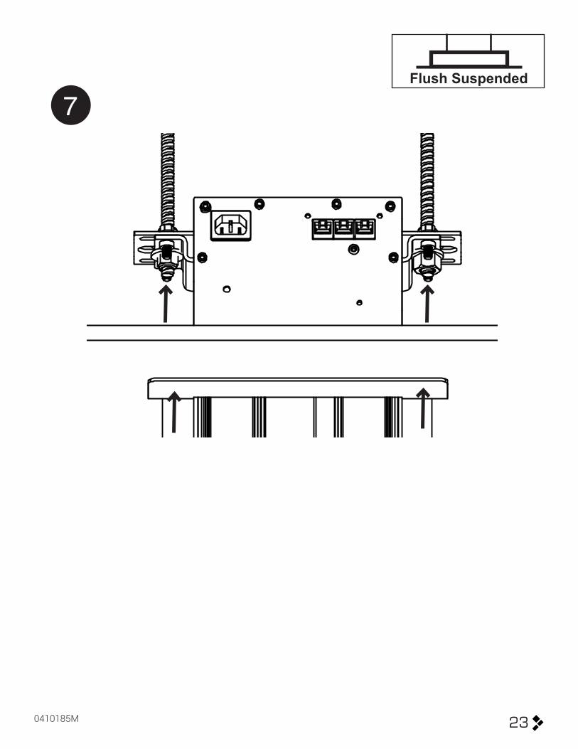
23
Flush Suspended
0410185M
7

24
Flush Suspended
8
9
25
Flush Suspended
0410185M
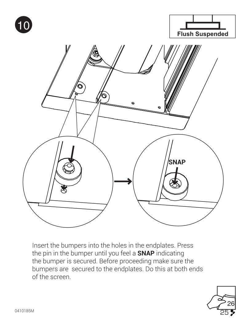
10
Insert the bumpers into the holes in the endplates. Press the pin in the bumper until you feel a SNAP indicating the bumper is secured. Before proceeding make sure the bumpers are secured to the endplates. Do this at both ends of the screen.
SNAP
26

5 MOTORIZED
26
IEC Connection
1
2
0410185M 27
5 MOTORIZEDPigtail Connection
NEUTRAL 110V White220V Blue
HOT
GROUND
110V Black220V Brown
110V Green220V Green and White
6ft (1.83m)

5 MOTORIZED
28
CONTROLS
RJ45 Inputs (3X)
Low Voltage Trigger Input (1/8’’ (3.5mm) mono)
RJ45 Input inside case

0410185M 29
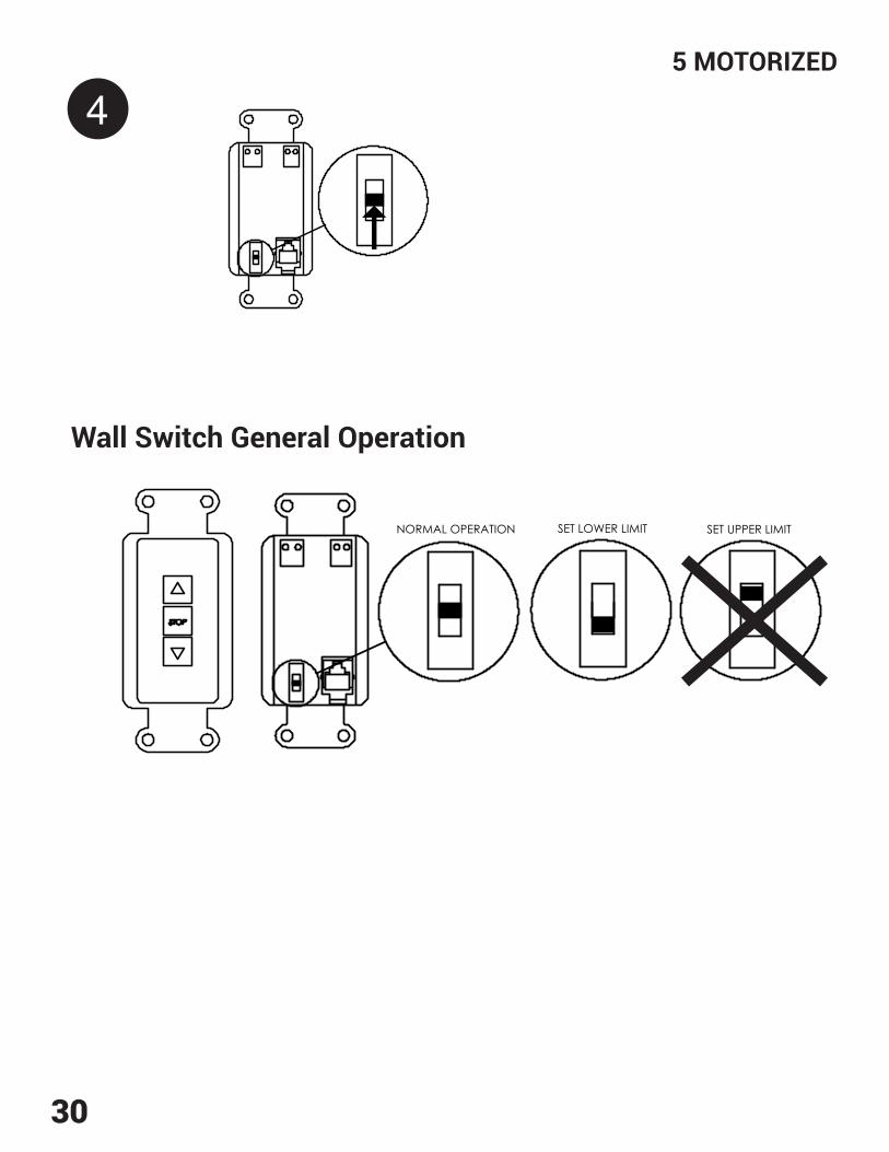
5 MOTORIZEDSETTING THE LOWER LIMIT
9 ft (2.75m) ProvidedIf Longer cable must be shielded
RJ45RJ9
Wall Switch
1
2
3 Desired Drop
Projected Image
5 MOTORIZED
30
4
NORMAL OPERATION SET UPPER LIMITSET LOWER LIMIT
Wall Switch General Operation

0410185M 31
5 MOTORIZED
34 36
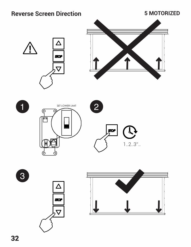
Reverse Screen Direction
5 MOTORIZED
32
NORMAL OPERATION SET UPPER LIMITSET LOWER LIMIT
3
Reverse Screen Direction
1 2NORMAL OPERATION SET UPPER LIMITSET LOWER LIMIT
1..2..3’’..
330410185M
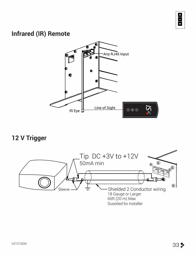
Infrared (IR) Remote
12 V Trigger
Any RJ45 Input
IR EyeLine of Sight
Tip DC +3V to +12V50mA min
Sleeve18 Gauge or Larger Shielded 2 Conductor wiring
65ft (20 m) MaxSupplied by installer
34
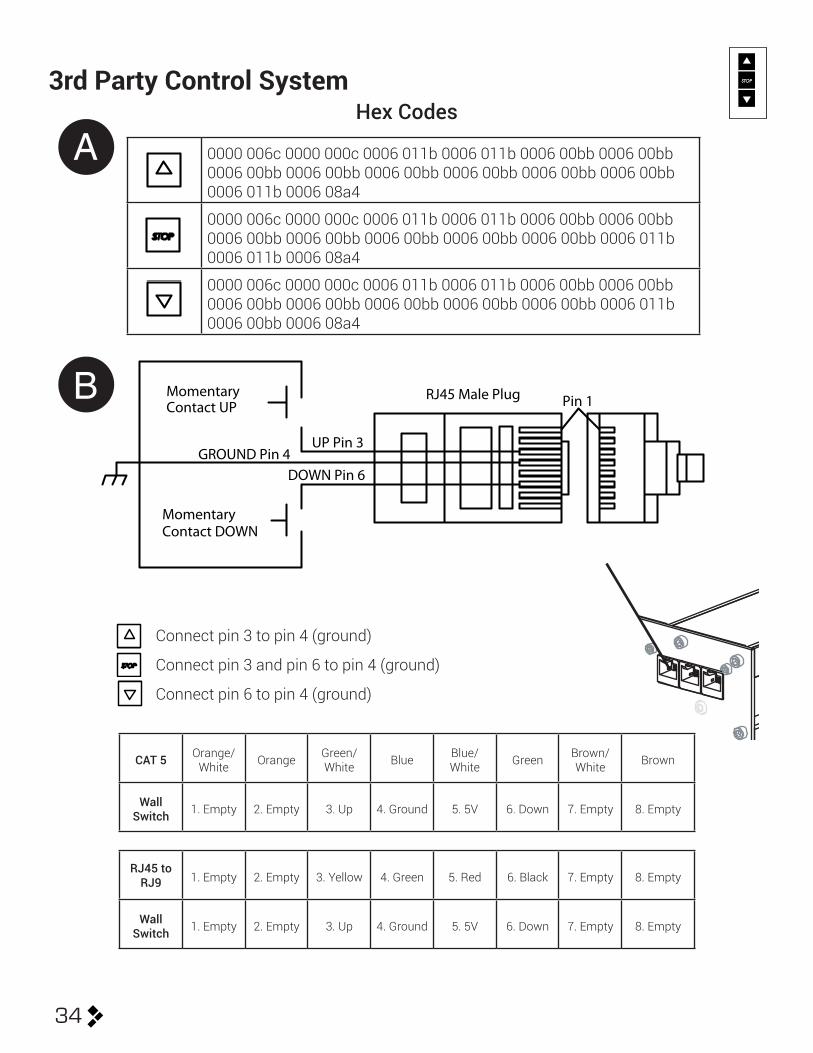
Pin 1
UP Pin 3GROUND Pin 4
DOWN Pin 6
MomentaryContact UP
MomentaryContact DOWN
RJ45 Male Plug
3rd Party Control SystemHex Codes
0000 006c 0000 000c 0006 011b 0006 011b 0006 00bb 0006 00bb 0006 00bb 0006 00bb 0006 00bb 0006 00bb 0006 00bb 0006 00bb 0006 011b 0006 08a4
0000 006c 0000 000c 0006 011b 0006 011b 0006 00bb 0006 00bb 0006 00bb 0006 00bb 0006 00bb 0006 00bb 0006 00bb 0006 011b 0006 011b 0006 08a4
0000 006c 0000 000c 0006 011b 0006 011b 0006 00bb 0006 00bb 0006 00bb 0006 00bb 0006 00bb 0006 00bb 0006 00bb 0006 011b 0006 00bb 0006 08a4
A
B
Connect pin 3 to pin 4 (ground)
Connect pin 3 and pin 6 to pin 4 (ground)
Connect pin 6 to pin 4 (ground)
CAT 5 Orange/White Orange Green/
White Blue Blue/White Green Brown/
White Brown
Wall Switch 1. Empty 2. Empty 3. Up 4. Ground 5. 5V 6. Down 7. Empty 8. Empty
RJ45 to RJ9 1. Empty 2. Empty 3. Yellow 4. Green 5. Red 6. Black 7. Empty 8. Empty
Wall Switch 1. Empty 2. Empty 3. Up 4. Ground 5. 5V 6. Down 7. Empty 8. Empty
0410185M 35
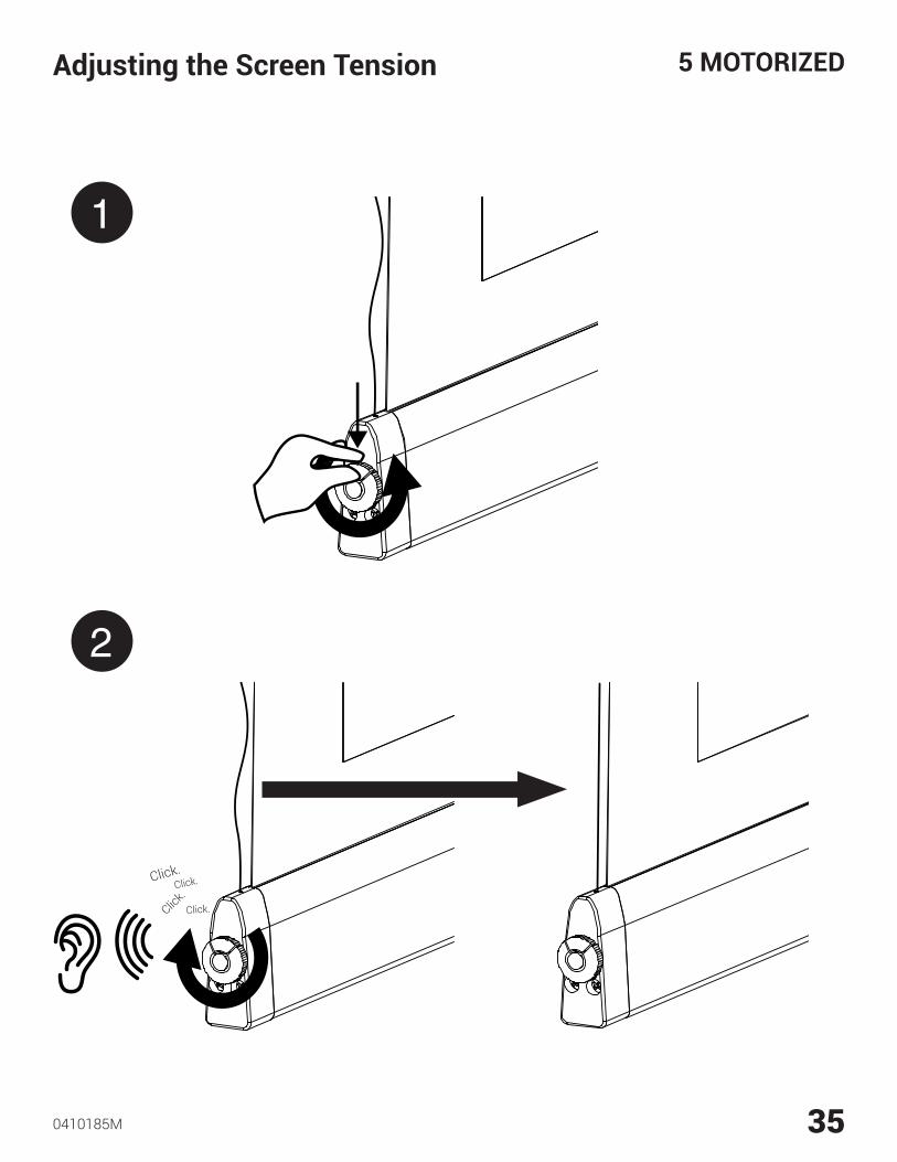
5 MOTORIZEDAdjusting the Screen Tension
1
2
Click.
Click.
Click.
Click.
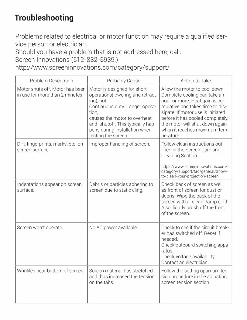
Problems related to electrical or motor function may require a qualified ser-vice person or electrician.Should you have a problem that is not addressed here, call: Screen Innovations (512-832-6939.)http://www.screeninnovations.com/category/support/
Problem Description Probably Cause Action to Take
Motor shuts off. Motor has been in use for more than 2 minutes.
Motor is designed for short operations(lowering and retract-ing), notContinuous duty. Longer opera-tion,causes the motor to overheat and shutoff. This typically hap-pens during installation when testing the screen.
Allow the motor to cool down.Complete cooling can take an hour or more. Heat gain is cu-mulative and takes time to dis-sipate. If motor use is initiated before it has cooled completely, the motor will shut down again when it reaches maximum tem-perature.
Dirt, fingerprints, marks, etc. on screen surface.
Improper handling of screen. Follow clean instructions out-lined in the Screen Care and Cleaning Section.
https://www.screeninnovations.com/category/support/faq/general/#how-to-clean-your-projection-screen
Indentations appear on screen surface.
Debris or particles adhering to screen due to static cling.
Check back of screen as well as front of screen for dust or debris. Wipe the back of the screen with a clean damp cloth. Also, lightly brush off the front of the screen.
Screen won’t operate. No AC power available. Check to see if the circuit break-er has switched off. Reset if needed.Check outboard switching appa-ratus.Check voltage availability.Contact an electrician.
Wrinkles near bottom of screen. Screen material has stretched and thus increased the tension on the tabs.
Follow the setting optimum ten-sion procedure in the adjusting screen tension section.
Troubleshooting

NOTES

NOTES

NOTES

NOTES