500kwp floating solar power plant at banasura sagar – an ... · floating solar power plant is...
TRANSCRIPT

500kWp Floating Solar Power Plant At Banasura Sagar Kerala
– An Overview
KERALA STATE ELECTRICITY BOARD LTD

Introduction
The Banasura sagar 500kWp Floating solar power plant situated inKerala , the largest of its kind in India is commissioned recently in
the Banasura sagar reservoir, an innovative project done by theKerala State Electricity Board Ltd
KERALA STATE ELECTRICITY BOARD LTD

Introduction
Project Location
The project is located in the Banasura sagar dam reservoir in thestate of kerala , a dam originally constructed in the year 2005
for the purpose of the irrigation
and reservoir in the Karamanth-
odu a tributary of Kabani river
and later for Kakkayam Gener-
ating station of kerala State Electricity
board ltd
KERALA STATE ELECTRICITY BOARD LTD

Brief History of the project
Pilot floating solar project at Banasura sagar Dam
KSEBL has been considering Floating solar power plants from 2013 onward . Kerala State Electricity Board (L) has
successfully tested and commissioned a 10 kW floating solar power plant using ferro cement platform as a start up project before taking up the 500 kW project
KERALA STATE ELECTRICITY BOARD LTD

Introduction to floating solar power plants
KERALA STATE ELECTRICITY BOARD LTD
Salient features of Floating Solar power plants
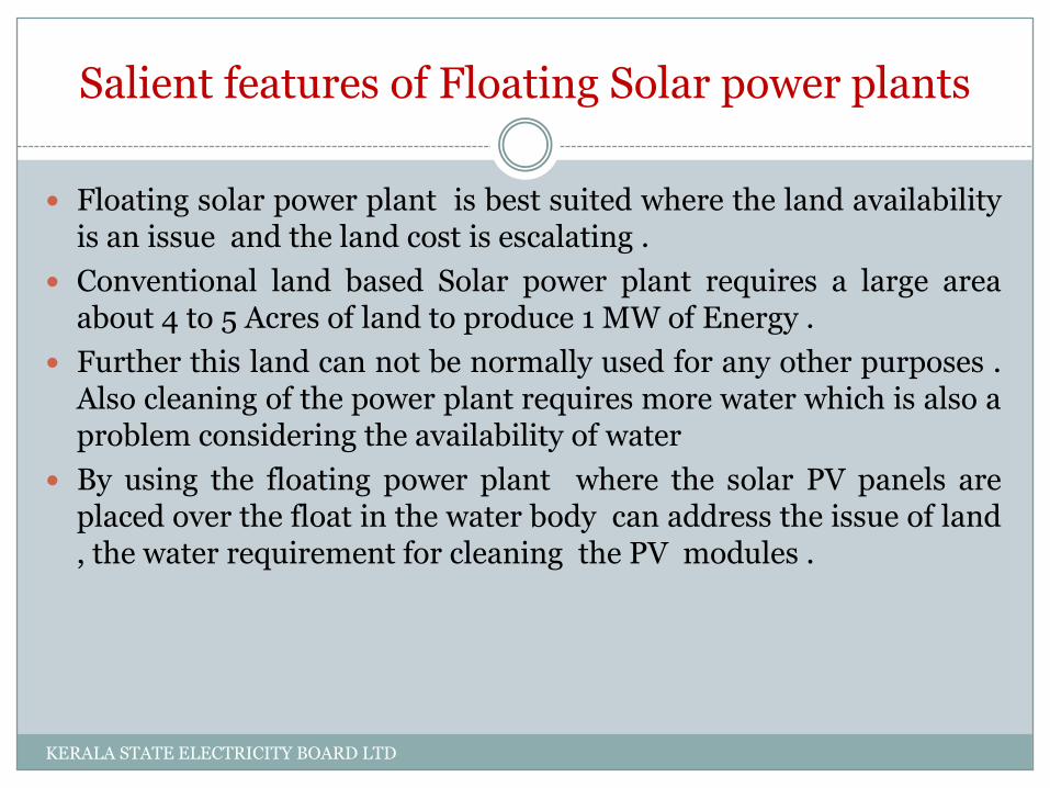
Floating solar power plant is best suited where the land availabilityis an issue and the land cost is escalating .
Conventional land based Solar power plant requires a large areaabout 4 to 5 Acres of land to produce 1 MW of Energy .
Further this land can not be normally used for any other purposes .Also cleaning of the power plant requires more water which is also aproblem considering the availability of water
By using the floating power plant where the solar PV panels areplaced over the float in the water body can address the issue of land, the water requirement for cleaning the PV modules .
KERALA STATE ELECTRICITY BOARD LTD
Floating solar power plant conversion efficiency is morecompared to the plants installed at the land due to reducedtemperature in the PV modules in floating environment .
Another advantage of the plant is that it reduces theevaporation from the reservoir thereby conserving the water.
The floating solar power plant can be installed in reservoirs ,ponds and lakes and other water bodies including sea .
KERALA STATE ELECTRICITY BOARD LTD

Components of floating solar power plant
KERALA STATE ELECTRICITY BOARD LTD

Major Components of the Banasura SagarFloating power plant
The float made up of ferro cement platform
The Mooring and anchoring system
The PV modules and panels
The string inverter
The low voltage AC cables and its protection
The step up transformer and HV cables
The HV cable Management system
The Scada system
The earthing and lighting protection
Weather monitoring system
KERALA STATE ELECTRICITY BOARD LTD

Floating plat form
There are 17 plat forms made of Ferro cement which is used for placing the solar panels and inverter
A central plat form for the substation and control room and Scadasystem
The float is held in place by seaflex mooring and anchoring system.
The total area of the float is 1.23 acres
Construction of the ferrocement plat form
The platforms are constructed at the shore and later pulled to the location of the plant
KERALA STATE ELECTRICITY BOARD LTD

Ferro cement platforms
The construction site of the ferro cement platformsKERALA STATE ELECTRICITY BOARD LTD

Mooring and anchoring system
TheMooring and anchoring is used to keep the float in position againstthe external forces and water level variations
KERALA STATE ELECTRICITY BOARD LTD

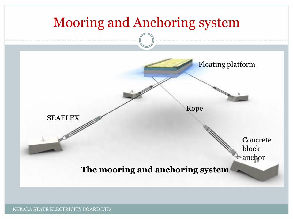
Mooring and Anchoring system
This project uses the SEAFLEX mooring system which consists of a SEAFLEX and a rope to hold the float in position against external forces and water level
The SEAFLEX is the active part of the mooring, adjusting for water level changes while also taking care of forces.
SEAFLEX is always tensioned at lowest water level.
KERALA STATE ELECTRICITY BOARD LTD
Mooring and Anchoring system
SEAFLEX
Rope
Concreteblock anchor
Floating platform
The mooring and anchoring system
KERALA STATE ELECTRICITY BOARD LTD

Mooring and Anchoring
Location Banasurasagar Reservoir, India
Max wind speed 32m/s at 10 m height
Depth at lowest water level Avg. 15 m
Water level variationDesign Lowest Water Level: 755.5 ref. to MSL
Total Water Level Variation: 20.74m
Wave height 0.3 m (H significant)
Current - (No current)
Dimensioning Parameters
KERALA STATE ELECTRICITY BOARD LTD

Mooring and Anchoring system
Position of the anchors and mooring system as per design
KERALA STATE ELECTRICITY BOARD LTD

PV Panel Placements
Placement of PV panels on the plat form
The PV arrays are placed over the plat form in two ways
1. on Ferro-cement Platform
2. on Water Body
•PV PANELS ON FERROCEMENT ON WATER BODY
KERALA STATE ELECTRICITY BOARD LTD

PV panel placement
Even though the temperature of the panels are lower as it is on the floating water ,specific attention was given to place the panels directly over the water body by suitable design of the plat form as shown in the picture . Investigation is on for comparing the efficiency of the Floating PV plant with that of the nearby dam top solar power plant
KERALA STATE ELECTRICITY BOARD LTD
Electrical schemes
KERALA STATE ELECTRICITY BOARD LTD

Details of PV module
W 260
Maximum Peak Voltage, Vmp V 31.60
Maximum Peak Current, Imp A 8.23
Open Circuit Voltage, Voc V 37.73
Short Circuit Current, Isc A 8.96
Maximum System Voltage V 1000
Electrical details of the PV module
Solar Panel – Radiant Solar RS260P – 60
KERALA STATE ELECTRICITY BOARD LTD

Configuration of PV modules
String details
Number of String inverters 17
Number of strings connected
to each inverter
5
Number of Modules
connected in each string
23
Total DC voltage of string Vdc
= 37.73 x 23
867.79V <
1000V
(Vdc_max)
Max Mppt Voltage Mppt =
31.6x 23
726.80V > 610V
(Vstart)
Idc = Isc x Number of panels
in parallel (8.96 x 5)
44.8A< 80A
(Isc_max)
Imppt = Vmp x Number of
panels in parallel (8.23x5)
41.15A < 58A
(Imppt_max
KERALA STATE ELECTRICITY BOARD LTD
Grid connectivity
11kV substation and Grid synchronisation
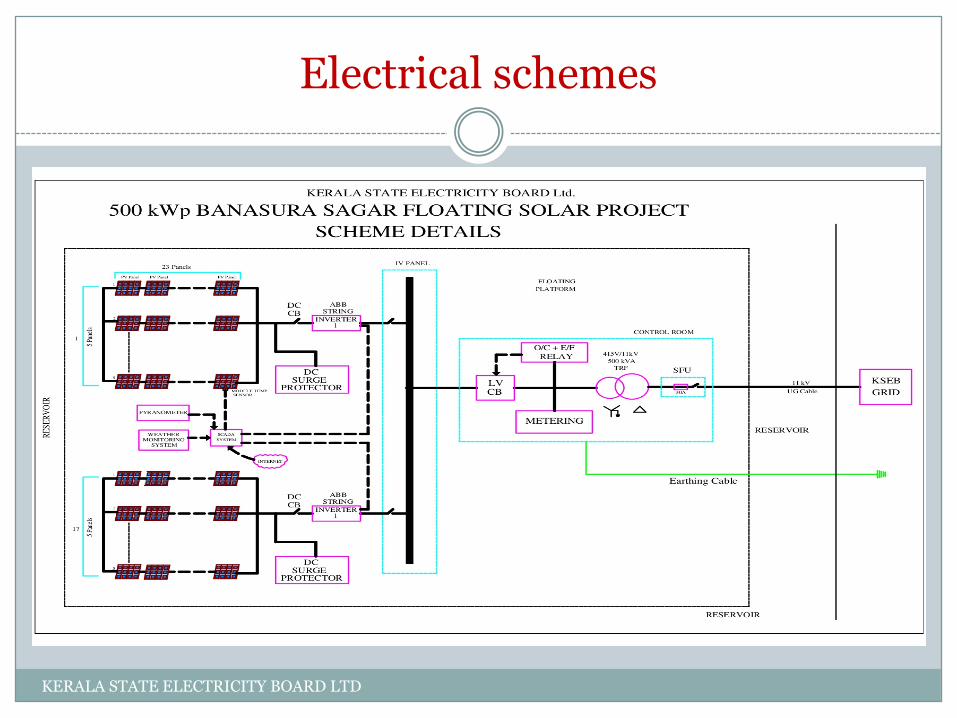
The 11kV substation with 415/11 kV 500kVA , Star- Delta Power
Transformer is placed on the central platform and the gridsynchronization is done in the float .
The power from the float is evacuated to the shore through a 11kVXPPE power cable specially designed for the application
Net metering is placed in the HV side of the plant
KERALA STATE ELECTRICITY BOARD LTD

11kV cable Management system
Cable Management system
Special graded 11kV cable is used for the transmitting the powergenerated in the floating solar plant to the KSEB grid . A cablemanagement system with pulleys are used for allowing the freemovement of the cable when the water level in the reservoir isvarying due to seasonal changes
KERALA STATE ELECTRICITY BOARD LTD
String inverter
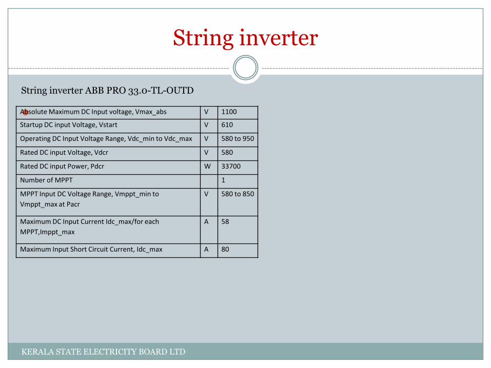
String inverter ABB PRO 33.0-TL-OUTD
Absolute Maximum DC Input voltage, Vmax_abs V 1100
Startup DC input Voltage, Vstart V 610
Operating DC Input Voltage Range, Vdc_min to Vdc_max V 580 to 950
Rated DC input Voltage, Vdcr V 580
Rated DC input Power, Pdcr W 33700
Number of MPPT 1
MPPT Input DC Voltage Range, Vmppt_min to
Vmppt_max at Pacr
V 580 to 850
Maximum DC Input Current Idc_max/for each
MPPT,Imppt_max
A 58
Maximum Input Short Circuit Current, Idc_max A 80
KERALA STATE ELECTRICITY BOARD LTD

SCADA SYSTEM
The Scada system in the plant is connected to the inverters , whether monitoring station and metering equipments, other monitoring devices . The scada system is having the facility for
Device monitoring – Inverters , Metering and Weather station
Alarms
Trends
Technical Reports and
Executive reports
KERALA STATE ELECTRICITY BOARD LTD

Scada system
SCADA SYSTEM SCREEN SHOTKERALA STATE ELECTRICITY BOARD LTD

Earthing
Earthing challenges As the substation used to step up the Voltage from 415 V to 11 kV
for synchronizing with the KSEBL grid , the 11 KV grid the Earthingprovided shall reduce the step and touch potential to a safer valueso as to avoid any possible hazard to the operating personal in theFloat .
Presently there is no international or Indian standard that can befollowed for the design of Earthing of floating solar plant with 11kVsubstation in the float ,
There is certain risk of fault current to be allowed to flow throughthe reservoir water .
However ,as per the IEEE 80005-1 ,the earthing method to befollowed while the ship takes short stay in the port and it take powersupply from the shore .
This is achieved by earthing the metallic structure of the substationdirectly to the shore by using redundant Insulated cable
KERALA STATE ELECTRICITY BOARD LTD

Relay and protection
Relay and protection
11 KV side of the plant is protected by the over current earthfault protection in the feeder connected to 33 kVPadinjarathara substation .
Over voltage , under voltage, over frequency, under frequencyprotection and anti islanding protection working in the activemode is set in the Inverter which trips and disconnects theinverter with the grid in case of abnormal conditions
LV side of the power transformer is protected by over currentand earth fault protection which trips the LV CB in case offaults in the AC cable between Inverter and the Transformer
KERALA STATE ELECTRICITY BOARD LTD

Conclusion
Conclusion. The details of the floating power plant and its installation on the
ferrocement float has been discussed in this report. The solar plant and the 11 kV substation are placed over the ferro cement platform and the DC to AC conversion is done near the plant itself as a result of which there is savings in the cost of the DC cable
As the power is converted to MV 11kV alternating current , the power loss is reduced in this typical design .
The mooring and anchoring system used in this plant has proven to sustain in recent heavy floods in kerala
Even though the cost of the ferro cement float is higher than that of HDPE panels , ferro cement plat form is made in the site itself which is certainly an advantage in difficult terrain
In this typical design , the 11kV substation is placed over the float and the float has the flexibility to place bigger capacity transformers in case of future expansion
KERALA STATE ELECTRICITY BOARD LTD

conclusion
The floating plant requires less space compared to land based plants . The area requirement for the Banasura Project is app 1.23 acres for 0.5 MW where as the land requirement for equvalant land based system is 2 to 2.5 acres
The floating solar environment especially in the reservoir will be comparatively cleaner than that of land based power plant and hence the maintenance cycle can be reduced
There is no land cost or land development cost etc in floating solar power plant and the floating plant can be installed in short time comparatively
The power evacuation cost of the floating plant in the reservoir connected with the hydro plant will be less as there will be nearby substations for the hydro plants
KERALA STATE ELECTRICITY BOARD LTD

Conclusion
The shadow in the reservoir will be comparatively low and hence the available power generation time in the floating solar will be more than that of land based pV plants
Floating plants if used in the cooling reservoirs will have the advantage of less water evaporation and the better utilization of the available space
The efficiency of the plant is directly related to the cleanliness of the modules . The PV modules can be easily cleaned in floating plants . Also the reservoir water can be used for cooling of the modules which in turn increases the efficiency
KERALA STATE ELECTRICITY BOARD LTD

Future improvements and suggestions
Future improvements and suggestions based on the experince Even though the floating solar power plant efficiency increases with the
reduced panel temperature , there is large difference noticed with ambient temperature and the module temperature especially during the peak time of the day . An automatic cooling system using the water in the reservoir that operates based on the temperature information from the sensor can be used to bring down the module temperature and the efficiency of the plant can be improved .
The equipotential earthing achieved by connecting the metal parts of the floating solar to the remote shore is very vital for the safety of the operating personal . Hence by introducing an earthing monitoring system that can be connected to the Scada system , which monitors the condition of the earth can be used for further improving the safety of earthing
Water level variation and flow velocity variations are important factors in mooring system design hence while identifying sites including dam reservoirs these factors have to be analyzed.
KERALA STATE ELECTRICITY BOARD LTD

Future improvements and suggestions
Earthing of the floating solar power plant especially when thesubstation is in the float need to be analyzed and designed to seethat it meets all safety and protection requirements
Banasura Sagar floating solar power plant is taken up as aninnovative project as floating solar projects are relatively a newconcept and hence project cost aspect need to be controlled infuture projects considering other options for floats .
KERALA STATE ELECTRICITY BOARD LTD