500se second stage - hollis · 2014. 12. 4. · 1. snip the plastic ty-strap (25) that holds the...
TRANSCRIPT
SUPPORT: TOLL-FREE 888-383-DIVE • FAX 510-729-5115 • E-MAIL [email protected]
This 500SE Service Procedure conveys a list of components and service procedures that reflect the 500SE as it was configured at the time of this writing.
Doc. 12-4095-r04 (11/25/14)
500SESECOND STAGE
SERVICE PROCEDURE
Doc. 12-4095-r04 (11/25/14)2
500SE SERVICE GUIDE
SUPPORT: TOLL-FREE 888-383-DIVE • FAX 510-729-5115 • E-MAIL [email protected]
© 2002 DESIGN (2013)
CONTENTS
TROUBLESHOOTING ................................................................................................................................................. 3
DISASSEMBLY PROCEDURE ..................................................................................................................................... 5
REASSEMBLY PROCEDURE ...................................................................................................................................... 9
FINAL TUNING AND TESTING ................................................................................................................................. 13
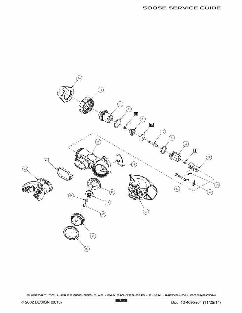
PARTS LIST AND EXPLODED VIEW DIAGRAM ....................................................................................................... 15
SPECIFICATIONS
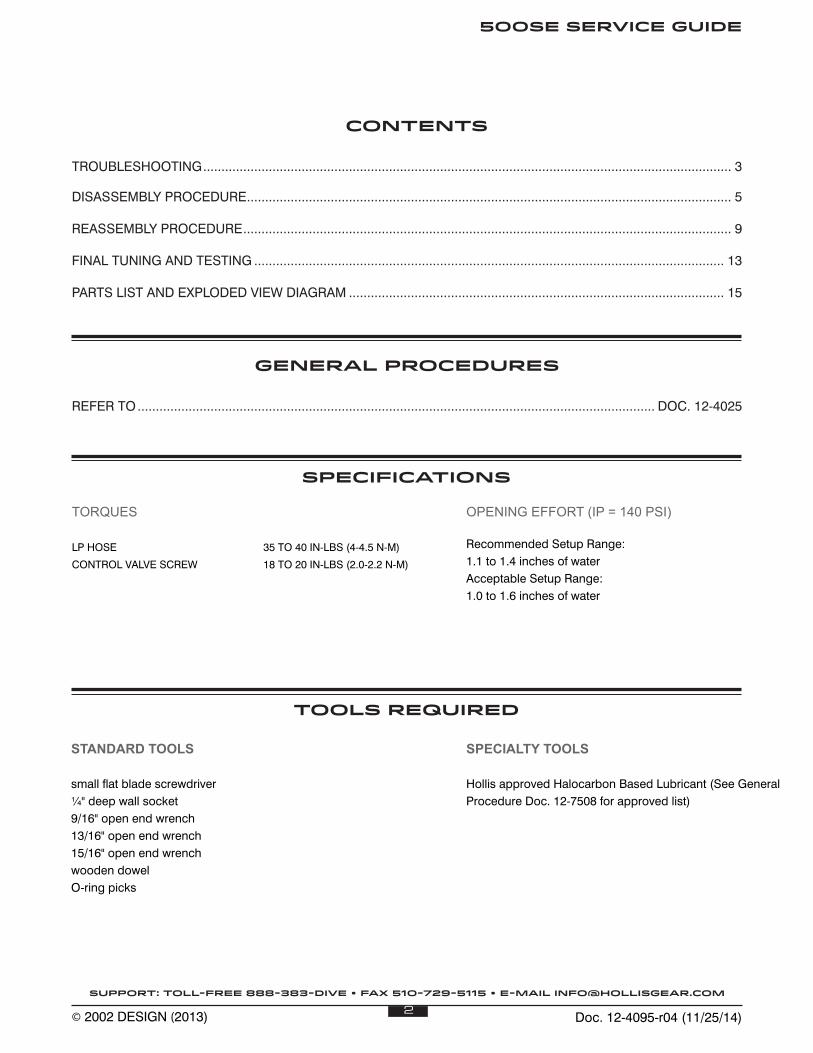
TORQUES
LP HOSE 35 TO 40 IN-LBS (4-4.5 N-M)
CONTROL VALVE SCREW 18 TO 20 IN-LBS (2.0-2.2 N-M)
GENERAL PROCEDURES
REFER TO .............................................................................................................................................. DOC. 12-4025
TOOLS REQUIRED
STANDARD TOOLS
small flat blade screwdriver¼" deep wall socket9/16" open end wrench13/16" open end wrench15/16" open end wrenchwooden dowelO-ring picks
SPECIALTY TOOLS
Hollis approved Halocarbon Based Lubricant (See General Procedure Doc. 12-7508 for approved list)
OPENING EFFORT (IP = 140 PSI)
Recommended Setup Range:1.1 to 1.4 inches of waterAcceptable Setup Range:1.0 to 1.6 inches of water
Doc. 12-4095-r04 (11/25/14)3
500SE SERVICE GUIDE
SUPPORT: TOLL-FREE 888-383-DIVE • FAX 510-729-5115 • E-MAIL [email protected]
© 2002 DESIGN (2013)
TROUBLESHOOTING
SYMPTOMS POSSIBLE CAUSE TREATMENT
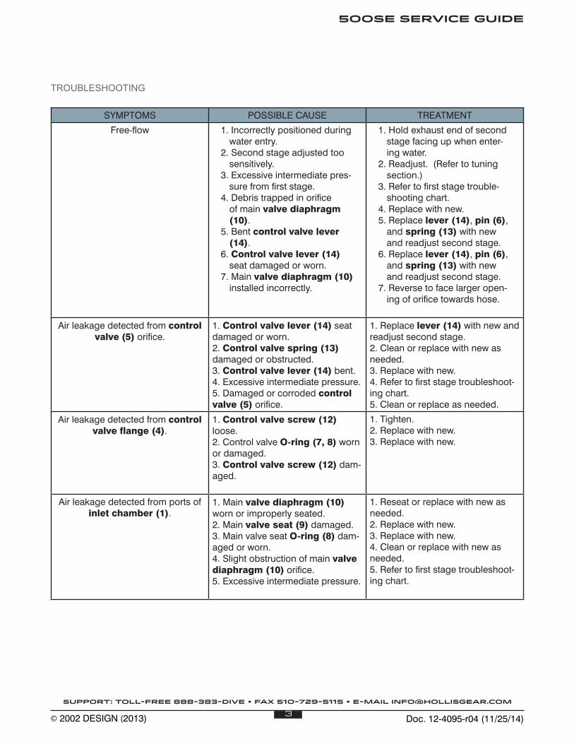
Free-flow 1. Incorrectly positioned during water entry.
2. Second stage adjusted too sensitively.
3. Excessive intermediate pres-sure from first stage.
4. Debris trapped in orifice of main valve diaphragm (10).
5. Bent control valve lever (14).
6. Control valve lever (14) seat damaged or worn.
7. Main valve diaphragm (10) installed incorrectly.
1. Hold exhaust end of second stage facing up when enter-ing water.
2. Readjust. (Refer to tuning section.)
3. Refer to first stage trouble-shooting chart.
4. Replace with new.5. Replace lever (14), pin (6),
and spring (13) with new and readjust second stage.
6. Replace lever (14), pin (6), and spring (13) with new and readjust second stage.
7. Reverse to face larger open-ing of orifice towards hose.
Air leakage detected from control valve (5) orifice.
1. Control valve lever (14) seat damaged or worn.2. Control valve spring (13) damaged or obstructed.3. Control valve lever (14) bent.4. Excessive intermediate pressure.5. Damaged or corroded control valve (5) orifice.
1. Replace lever (14) with new and readjust second stage.2. Clean or replace with new as needed.3. Replace with new.4. Refer to first stage troubleshoot-ing chart.5. Clean or replace as needed.
Air leakage detected from control valve flange (4).
1. Control valve screw (12) loose.2. Control valve O-ring (7, 8) worn or damaged.3. Control valve screw (12) dam-aged.
1. Tighten.2. Replace with new.3. Replace with new.
Air leakage detected from ports of inlet chamber (1).
1. Main valve diaphragm (10) worn or improperly seated.2. Main valve seat (9) damaged.3. Main valve seat O-ring (8) dam-aged or worn.4. Slight obstruction of main valve diaphragm (10) orifice.5. Excessive intermediate pressure.
1. Reseat or replace with new as needed.2. Replace with new.3. Replace with new.4. Clean or replace with new as needed.5. Refer to first stage troubleshoot-ing chart.
Doc. 12-4095-r04 (11/25/14)4
500SE SERVICE GUIDE
SUPPORT: TOLL-FREE 888-383-DIVE • FAX 510-729-5115 • E-MAIL [email protected]
© 2002 DESIGN (2013)
SYMPTOMS POSSIBLE CAUSE TREATMENT
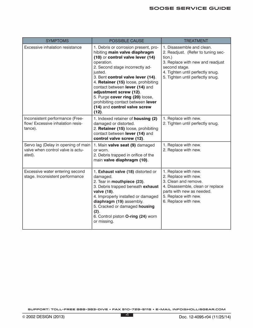
Excessive inhalation resistance 1. Debris or corrosion present, pro-hibiting main valve diaphragm (10) or control valve lever (14) operation.2. Second stage incorrectly ad-justed.3. Bent control valve lever (14).4. Retainer (15) loose, prohibiting contact between lever (14) and adjustment screw (12).5. Purge cover ring (20) loose, prohibiting contact between lever (14) and control valve screw (12).
1. Disassemble and clean.2. Readjust. (Refer to tuning sec-tion.)3. Replace with new and readjust second stage.4. Tighten until perfectly snug.5. Tighten until perfectly snug.
Inconsistent performance (Free-flow/ Excessive inhalation resis-tance).
1. Indexed retainer of housing (2) damaged or distorted.2. Retainer (15) loose, prohibiting contact between lever (14) and control valve screw (12).
1. Replace with new.2. Tighten until perfectly snug.
Servo lag (Delay in opening of main valve when control valve is actu-ated).
1. Main valve seat (9) damaged or worn.2. Debris trapped in orifice of the main valve diaphragm (10).
1. Replace with new.2. Replace with new.
Excessive water entering second stage. Inconsistent performance
1. Exhaust valve (18) distorted or damaged.2. Tear in mouthpiece (23).3. Debris trapped beneath exhaust valve (18).4. Improperly installed or damaged diaphragm (19) assembly.5. Cracked or damaged housing (2).6. Control piston O-ring (24) worn or missing.
1. Replace with new.2. Replace with new.3. Clean and remove.4. Disassemble, clean or replace parts with new as needed.5. Replace with new.6. Replace with new.
Doc. 12-4095-r04 (11/25/14)5
500SE SERVICE GUIDE
SUPPORT: TOLL-FREE 888-383-DIVE • FAX 510-729-5115 • E-MAIL [email protected]
© 2002 DESIGN (2013)
DISASSEMBLY PROCEDURE
! NOTE: Be sure to perform the steps outlined in the Initial Inspection Procedures prior to disassembling the regula-tor. Review the troubleshooting section to gain a better idea of which internal parts may be worn, and to better advise your customer of the service that is needed.
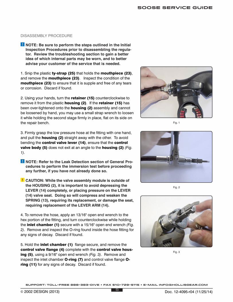
1. Snip the plastic ty-strap (25) that holds the mouthpiece (23), and remove the mouthpiece (23). Inspect the condition of the mouthpiece (23) to ensure that it is supple and free of any tears or corrosion. Discard if found.
2. Using your hands, turn the retainer (15) counterclockwise to remove it from the plastic housing (2). If the retainer (15) has been over-tightened onto the housing (2) assembly and cannot be loosened by hand, you may use a small strap wrench to loosen it while holding the second stage firmly in place, flat on its side on the repair bench.
3. Firmly grasp the low pressure hose at the fitting with one hand, and pull the housing (2) straight away with the other. To avoid bending the control valve lever (14), ensure that the control valve body (5) does not exit at an angle to the housing (2) (Fig. 1).
! NOTE: Refer to the Leak Detection section of General Pro-cedures to perform the immersion test before proceeding any further, if you have not already done so.
! CAUTION: While the valve assembly module is outside of the HOUSING (2), it is important to avoid depressing the LEVER (14) completely, or placing pressure on the LEVER (14) valve seat. Doing so will compress and weaken the SPRING (13), requiring its replacement, or damage the seat, requiring replacement of the LEVER ARM (14).
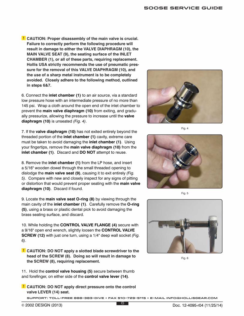
4. To remove the hose, apply an 13/16" open end wrench to the hex portion of the fitting, and turn counterclockwise while holding the inlet chamber (1) secure with a 15/16" open end wrench (Fig. 2). Remove and inspect the O-ring found inside the hose fitting for any signs of decay. Discard if found.
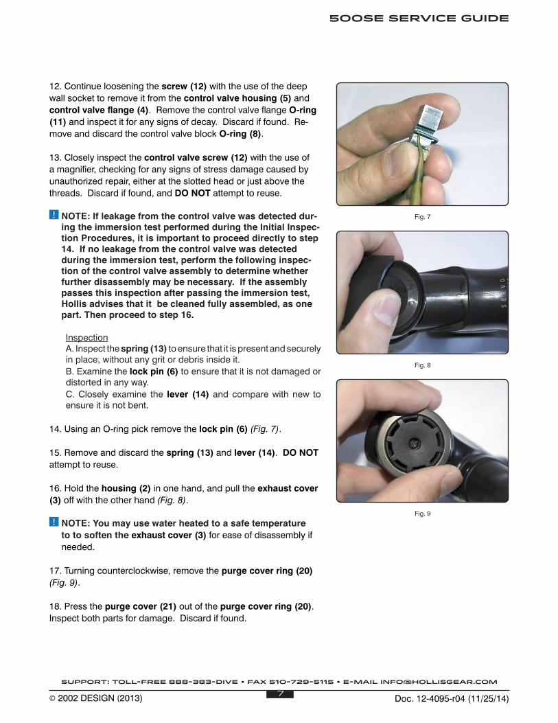
5. Hold the inlet chamber (1) flange secure, and remove the control valve flange (4) complete with the control valve hous-ing (5), using a 9/16" open end wrench (Fig. 3). Remove and inspect the inlet chamber O-ring (7) and control valve flange O-ring (11) for any signs of decay. Discard if found.
Fig. 1
Fig. 2
Fig. 3
Doc. 12-4095-r04 (11/25/14)6
500SE SERVICE GUIDE
SUPPORT: TOLL-FREE 888-383-DIVE • FAX 510-729-5115 • E-MAIL [email protected]
© 2002 DESIGN (2013)
! CAUTION: Proper disassembly of the main valve is crucial. Failure to correctly perform the following procedure will result in damage to either the VALVE DIAPHRAGM (10), the MAIN VALVE SEAT (9), the seating surface of the INLET CHAMBER (1), or all of these parts, requiring replacement. Hollis USA strictly recommends the use of pneumatic pres-sure for the removal of this VALVE DIAPHRAGM (10), and the use of a sharp metal instrument is to be completely avoided. Closely adhere to the following method, outlined in steps 6&7.
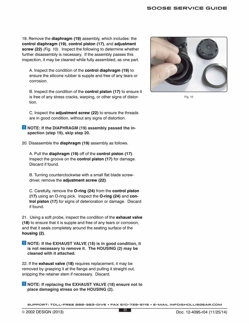
6. Connect the inlet chamber (1) to an air source, via a standard low pressure hose with an intermediate pressure of no more than 145 psi. Wrap a cloth around the open end of the inlet chamber to prevent the main valve diaphragm (10) from exiting, and gradu-ally pressurize, allowing the pressure to increase until the valve diaphragm (10) is unseated (Fig. 4).
7. If the valve diaphragm (10) has not exited entirely beyond the threaded portion of the inlet chamber (1) cavity, extreme care must be taken to avoid damaging the inlet chamber (1). Using your fingertips, remove the main valve diaphragm (10) from the inlet chamber (1). Discard and DO NOT attempt to reuse.
8. Remove the inlet chamber (1) from the LP hose, and insert a 5/16" wooden dowel through the small threaded opening to dislodge the main valve seat (9), causing it to exit entirely (Fig. 5). Compare with new and closely inspect for any signs of pitting or distortion that would prevent proper seating with the main valve diaphragm (10). Discard if found.
9. Locate the main valve seat O-ring (8) by viewing through the main cavity of the inlet chamber (1). Carefully remove the O-ring (5), using a brass or plastic dental pick to avoid damaging the brass seating surface, and discard.
10. While holding the CONTROL VALVE FLANGE (4) secure with a 9/16" open end wrench, slightly loosen the CONTROL VALVE SCREW (12) with just one turn, using a 1/4" deep wall socket (Fig. 6).
! CAUTION: DO NOT apply a slotted blade screwdriver to the head of the SCREW (8). Doing so will result in damage to the SCREW (8), requiring replacement.
11. Hold the control valve housing (5) secure between thumb and forefinger, on either side of the control valve lever (14). ! CAUTION: DO NOT apply direct pressure onto the control
valve LEVER (14) seat.
Fig. 4
Fig. 5
Fig. 6
Doc. 12-4095-r04 (11/25/14)7
500SE SERVICE GUIDE
SUPPORT: TOLL-FREE 888-383-DIVE • FAX 510-729-5115 • E-MAIL [email protected]
© 2002 DESIGN (2013)
12. Continue loosening the screw (12) with the use of the deep wall socket to remove it from the control valve housing (5) and control valve flange (4). Remove the control valve flange O-ring (11) and inspect it for any signs of decay. Discard if found. Re-move and discard the control valve block O-ring (8).
13. Closely inspect the control valve screw (12) with the use of a magnifier, checking for any signs of stress damage caused by unauthorized repair, either at the slotted head or just above the threads. Discard if found, and DO NOT attempt to reuse.
! NOTE: If leakage from the control valve was detected dur-ing the immersion test performed during the Initial Inspec-tion Procedures, it is important to proceed directly to step 14. If no leakage from the control valve was detected during the immersion test, perform the following inspec-tion of the control valve assembly to determine whether further disassembly may be necessary. If the assembly passes this inspection after passing the immersion test, Hollis advises that it be cleaned fully assembled, as one part. Then proceed to step 16.
InspectionA. Inspect the spring (13) to ensure that it is present and securely in place, without any grit or debris inside it.B. Examine the lock pin (6) to ensure that it is not damaged or distorted in any way.C. Closely examine the lever (14) and compare with new to ensure it is not bent.
14. Using an O-ring pick remove the lock pin (6) (Fig. 7).
15. Remove and discard the spring (13) and lever (14). DO NOT attempt to reuse.
16. Hold the housing (2) in one hand, and pull the exhaust cover (3) off with the other hand (Fig. 8).
! NOTE: You may use water heated to a safe temperature to to soften the exhaust cover (3) for ease of disassembly if needed.
17. Turning counterclockwise, remove the purge cover ring (20) (Fig. 9).
18. Press the purge cover (21) out of the purge cover ring (20). Inspect both parts for damage. Discard if found.
Fig. 7
Fig. 8
Fig. 9
Doc. 12-4095-r04 (11/25/14)8
500SE SERVICE GUIDE
SUPPORT: TOLL-FREE 888-383-DIVE • FAX 510-729-5115 • E-MAIL [email protected]
© 2002 DESIGN (2013)
19. Remove the diaphragm (19) assembly, which includes: the control diaphragm (19), control piston (17), and adjustment screw (22) (Fig. 10). Inspect the following to determine whether further disassembly is necessary. If the assembly passes this inspection, it may be cleaned while fully assembled, as one part.
A. Inspect the condition of the control diaphragm (19) to ensure the silicone rubber is supple and free of any tears or corrosion.
B. Inspect the condition of the control piston (17) to ensure it is free of any stress cracks, warping, or other signs of distor-tion.
C. Inspect the adjustment screw (22) to ensure the threads are in good condition, without any signs of distortion.
! NOTE: If the DIAPHRAGM (19) assembly passed the in-spection (step 19), skip step 20.
20. Disassemble the diaphragm (19) assembly as follows.
A. Pull the diaphragm (19) off of the control piston (17). Inspect the groove on the control piston (17) for damage. Discard if found.
B. Turning counterclockwise with a small flat blade screw-driver, remove the adjustment screw (22).
C. Carefully, remove the O-ring (24) from the control piston (17) using an O-ring pick. Inspect the O-ring (24) and con-trol piston (17) for signs of deterioration or damage. Discard if found.
21. Using a soft probe, inspect the condition of the exhaust valve (18) to ensure that it is supple and free of any tears or corrosion, and that it seals completely around the seating surface of the housing (2).
! NOTE: If the EXHAUST VALVE (18) is in good condition, it is not necessary to remove it. The HOUSING (2) may be cleaned with it attached.
22. If the exhaust valve (18) requires replacement, it may be removed by grasping it at the flange and pulling it straight out, snipping the retainer stem if necessary. Discard.
! NOTE: If replacing the EXHAUST VALVE (18) ensure not to place damaging stress on the HOUSING (2).
Fig. 10
Doc. 12-4095-r04 (11/25/14)9
500SE SERVICE GUIDE
SUPPORT: TOLL-FREE 888-383-DIVE • FAX 510-729-5115 • E-MAIL [email protected]
© 2002 DESIGN (2013)
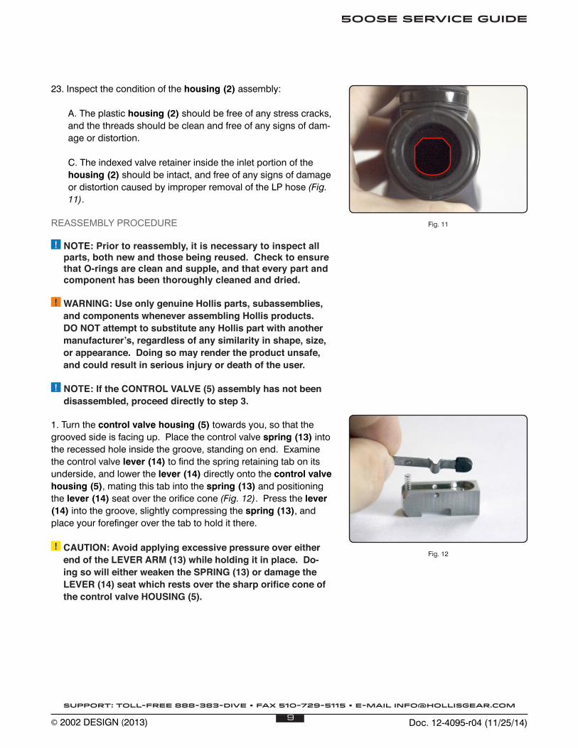
23. Inspect the condition of the housing (2) assembly:
A. The plastic housing (2) should be free of any stress cracks, and the threads should be clean and free of any signs of dam-age or distortion.
C. The indexed valve retainer inside the inlet portion of the housing (2) should be intact, and free of any signs of damage or distortion caused by improper removal of the LP hose (Fig. 11).
REASSEMBLY PROCEDURE
! NOTE: Prior to reassembly, it is necessary to inspect all parts, both new and those being reused. Check to ensure that O-rings are clean and supple, and that every part and component has been thoroughly cleaned and dried.
! WARNING: Use only genuine Hollis parts, subassemblies, and components whenever assembling Hollis products. DO NOT attempt to substitute any Hollis part with another manufacturer’s, regardless of any similarity in shape, size, or appearance. Doing so may render the product unsafe, and could result in serious injury or death of the user.
! NOTE: If the CONTROL VALVE (5) assembly has not been disassembled, proceed directly to step 3.
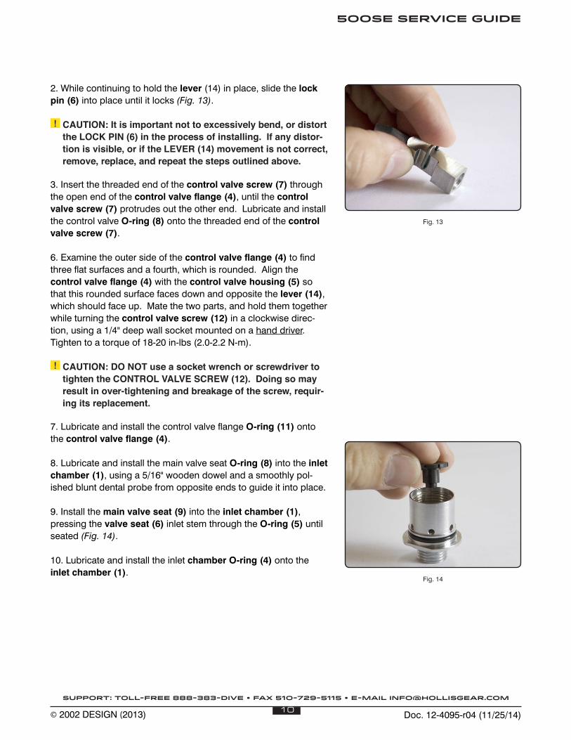
1. Turn the control valve housing (5) towards you, so that the grooved side is facing up. Place the control valve spring (13) into the recessed hole inside the groove, standing on end. Examine the control valve lever (14) to find the spring retaining tab on its underside, and lower the lever (14) directly onto the control valve housing (5), mating this tab into the spring (13) and positioning the lever (14) seat over the orifice cone (Fig. 12). Press the lever (14) into the groove, slightly compressing the spring (13), and place your forefinger over the tab to hold it there.
! CAUTION: Avoid applying excessive pressure over either end of the LEVER ARM (13) while holding it in place. Do-ing so will either weaken the SPRING (13) or damage the LEVER (14) seat which rests over the sharp orifice cone of the control valve HOUSING (5).
Fig. 12
Fig. 11
Doc. 12-4095-r04 (11/25/14)10
500SE SERVICE GUIDE
SUPPORT: TOLL-FREE 888-383-DIVE • FAX 510-729-5115 • E-MAIL [email protected]
© 2002 DESIGN (2013)
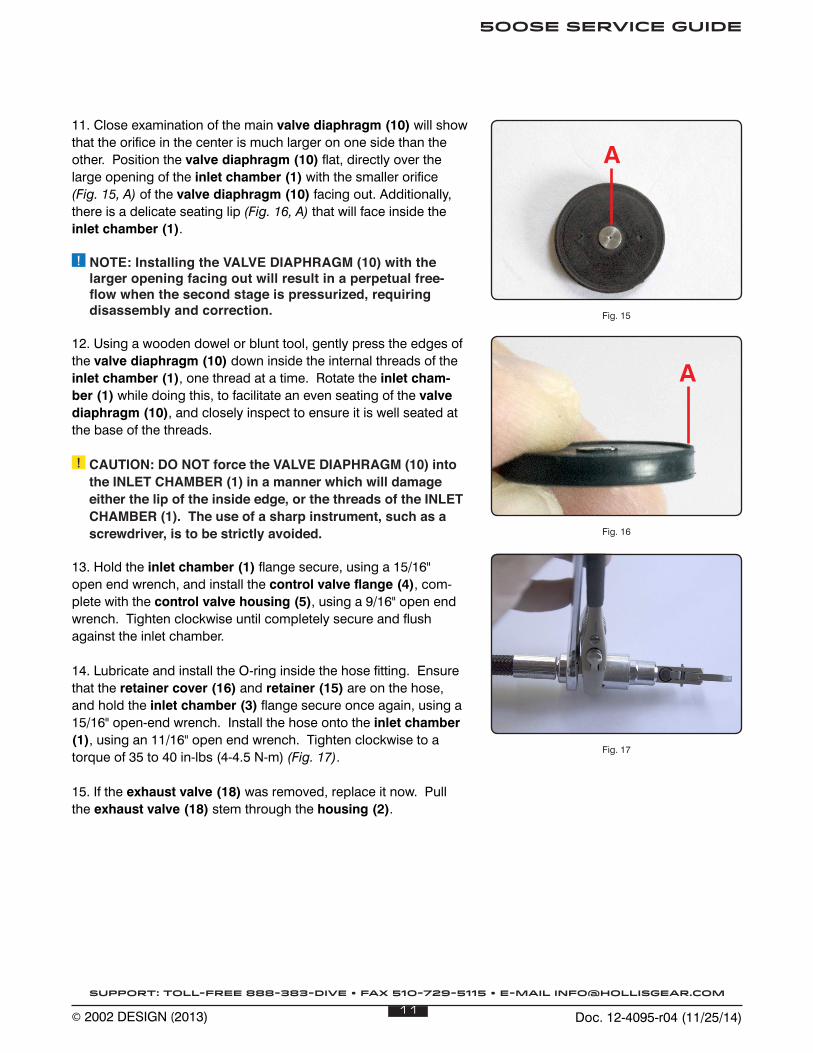
2. While continuing to hold the lever (14) in place, slide the lock pin (6) into place until it locks (Fig. 13). ! CAUTION: It is important not to excessively bend, or distort
the LOCK PIN (6) in the process of installing. If any distor-tion is visible, or if the LEVER (14) movement is not correct, remove, replace, and repeat the steps outlined above.
3. Insert the threaded end of the control valve screw (7) through the open end of the control valve flange (4), until the control valve screw (7) protrudes out the other end. Lubricate and install the control valve O-ring (8) onto the threaded end of the control valve screw (7).
6. Examine the outer side of the control valve flange (4) to find three flat surfaces and a fourth, which is rounded. Align the control valve flange (4) with the control valve housing (5) so that this rounded surface faces down and opposite the lever (14), which should face up. Mate the two parts, and hold them together while turning the control valve screw (12) in a clockwise direc-tion, using a 1/4" deep wall socket mounted on a hand driver. Tighten to a torque of 18-20 in-lbs (2.0-2.2 N-m). ! CAUTION: DO NOT use a socket wrench or screwdriver to
tighten the CONTROL VALVE SCREW (12). Doing so may result in over-tightening and breakage of the screw, requir-ing its replacement.
7. Lubricate and install the control valve flange O-ring (11) onto the control valve flange (4).
8. Lubricate and install the main valve seat O-ring (8) into the inlet chamber (1), using a 5/16" wooden dowel and a smoothly pol-ished blunt dental probe from opposite ends to guide it into place.
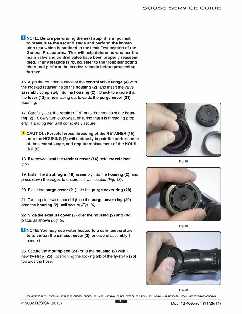
9. Install the main valve seat (9) into the inlet chamber (1), pressing the valve seat (6) inlet stem through the O-ring (5) until seated (Fig. 14).
10. Lubricate and install the inlet chamber O-ring (4) onto the inlet chamber (1).
Fig. 14
Fig. 13
Doc. 12-4095-r04 (11/25/14)11
500SE SERVICE GUIDE
SUPPORT: TOLL-FREE 888-383-DIVE • FAX 510-729-5115 • E-MAIL [email protected]
© 2002 DESIGN (2013)
11. Close examination of the main valve diaphragm (10) will show that the orifice in the center is much larger on one side than the other. Position the valve diaphragm (10) flat, directly over the large opening of the inlet chamber (1) with the smaller orifice (Fig. 15, A) of the valve diaphragm (10) facing out. Additionally, there is a delicate seating lip (Fig. 16, A) that will face inside the inlet chamber (1). ! NOTE: Installing the VALVE DIAPHRAGM (10) with the
larger opening facing out will result in a perpetual free-flow when the second stage is pressurized, requiring disassembly and correction.
12. Using a wooden dowel or blunt tool, gently press the edges of the valve diaphragm (10) down inside the internal threads of the inlet chamber (1), one thread at a time. Rotate the inlet cham-ber (1) while doing this, to facilitate an even seating of the valve diaphragm (10), and closely inspect to ensure it is well seated at the base of the threads. ! CAUTION: DO NOT force the VALVE DIAPHRAGM (10) into
the INLET CHAMBER (1) in a manner which will damage either the lip of the inside edge, or the threads of the INLET CHAMBER (1). The use of a sharp instrument, such as a screwdriver, is to be strictly avoided.
13. Hold the inlet chamber (1) flange secure, using a 15/16" open end wrench, and install the control valve flange (4), com-plete with the control valve housing (5), using a 9/16" open end wrench. Tighten clockwise until completely secure and flush against the inlet chamber.
14. Lubricate and install the O-ring inside the hose fitting. Ensure that the retainer cover (16) and retainer (15) are on the hose, and hold the inlet chamber (3) flange secure once again, using a 15/16" open-end wrench. Install the hose onto the inlet chamber (1), using an 11/16" open end wrench. Tighten clockwise to a torque of 35 to 40 in-lbs (4-4.5 N-m) (Fig. 17).
15. If the exhaust valve (18) was removed, replace it now. Pull the exhaust valve (18) stem through the housing (2).
Fig. 15
Fig. 16
Fig. 17
A
A
Doc. 12-4095-r04 (11/25/14)12
500SE SERVICE GUIDE
SUPPORT: TOLL-FREE 888-383-DIVE • FAX 510-729-5115 • E-MAIL [email protected]
© 2002 DESIGN (2013)
! NOTE: Before performing the next step, it is important to pressurize the second stage and perform the immer-sion test which is outlined in the Leak Test section of the General Procedures. This will help determine whether the main valve and control valve have been properly reassem-bled. If any leakage is found, refer to the troubleshooting chart and perform the needed remedy before proceeding further.
16. Align the rounded surface of the control valve flange (4) with the indexed retainer inside the housing (2), and insert the valve assembly completely into the housing (2). Check to ensure that the lever (12) is now facing out towards the purge cover (21) opening.
17. Carefully seat the retainer (15) onto the threads of the hous-ing (2). Slowly turn clockwise, ensuring that it is threading prop-erly. Hand tighten until completely secure.
! CAUTION: Forceful cross threading of the RETAINER (15) onto the HOUSING (2) will seriously impair the performance of the second stage, and require replacement of the HOUS-ING (2).
18. If removed, seat the retainer cover (16) onto the retainer (15).
19. Install the diaphragm (19) assembly into the housing (2), and press down the edges to ensure it is well seated (Fig. 18).
20. Place the purge cover (21) into the purge cover ring (20).
21. Turning clockwise, hand tighten the purge cover ring (20) onto the housing (2) until secure (Fig. 19).
22. Slide the exhaust cover (3) over the housing (2) and into place, as shown (Fig. 20).
! NOTE: You may use water heated to a safe temperature to to soften the exhaust cover (3) for ease of assembly if needed.
23. Secure the mouthpiece (23) onto the housing (2) with a new ty-strap (25), positioning the locking tab of the ty-strap (25) towards the hose.
Fig. 18
Fig. 19
Fig. 20
Doc. 12-4095-r04 (11/25/14)13
500SE SERVICE GUIDE
SUPPORT: TOLL-FREE 888-383-DIVE • FAX 510-729-5115 • E-MAIL [email protected]
© 2002 DESIGN (2013)
FINAL TUNING AND TESTING
First Stage Testing
1. Perform the Leak Detection Test specified in the Initial Inspec-tion Procedure for the first stage.
! NOTE: Refer to the Trouble Shooting section to determine the possible cause and treatment of any air leaks that may be found.
2. Connect the low pressure hose of the 500SE second stage to a low pressure port of the first stage. Ensure that all other ports are sealed with port plugs, with the exception of an additional low pressure quick disconnect hose.
3. Connect a recently calibrated low pressure test gauge to the additional low pressure hose, and connect the first stage to a pure breathing gas source of 3,000 psi.
4. Slowly open the valve to pressurize the regulator, and check the test gauge to ensure that the intermediate pressure is set as recommended in the specifications for the first stage being used.
! NOTE: If the intermediate pressure is found to be other than recommended, refer to that regulator's troubleshoot-ing section to determine possible cause and treatment.
Tuning
1. Prior to tuning the 500SE regulator, check the following items:
A. The retainer (15) should be securely installed into the hous-ing (2).
B. The adjustment screw (22) inside the diaphragm (24) assembly should be turned out counterclockwise as needed to avoid making contact with the lever (14).
C. The purge cover ring (20) should be securely installed into the housing (2).
D. The mouthpiece (23) should be cleaned and disinfected with warm, soapy water.
! NOTE: Steps A. & C. are essential to ensure correct contact between the ADJUSTMENT SCREW (22) and LEVER (14).
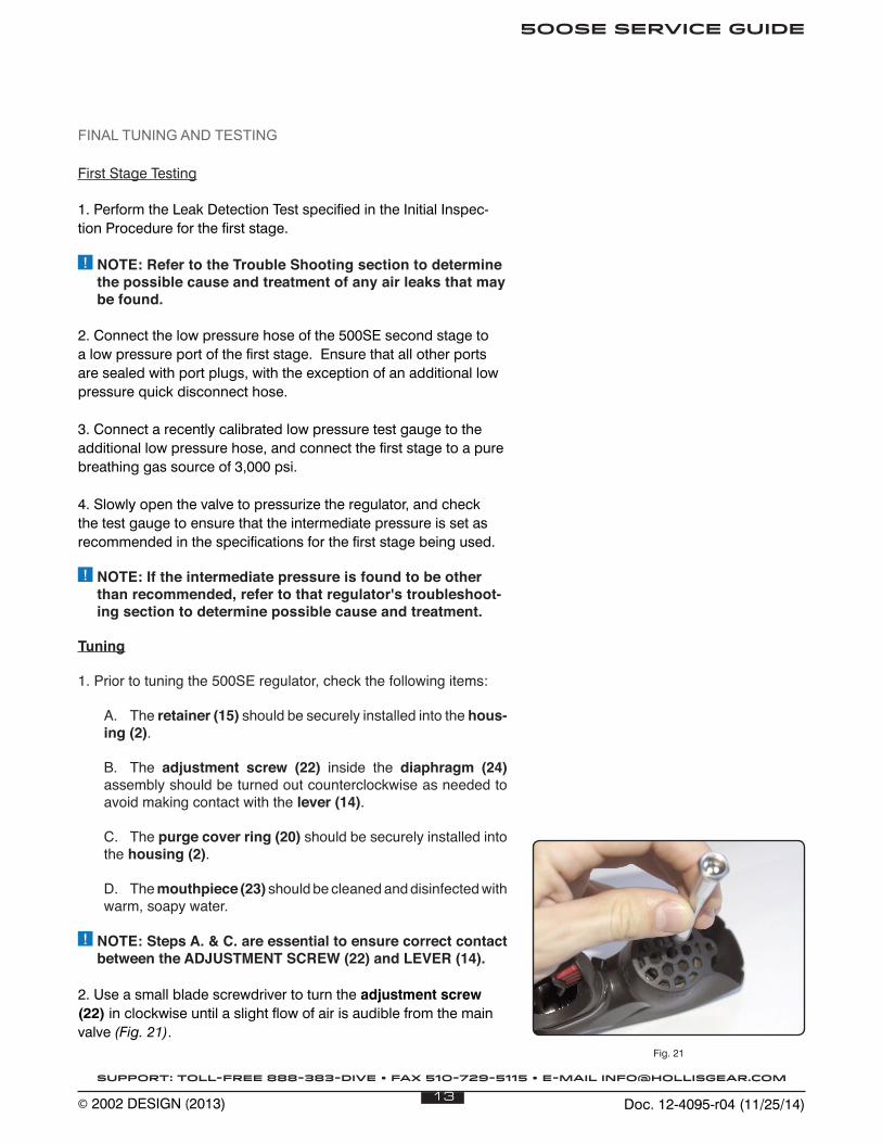
2. Use a small blade screwdriver to turn the adjustment screw (22) in clockwise until a slight flow of air is audible from the main valve (Fig. 21).
Fig. 21
Doc. 12-4095-r04 (11/25/14)14
500SE SERVICE GUIDE
SUPPORT: TOLL-FREE 888-383-DIVE • FAX 510-729-5115 • E-MAIL [email protected]
© 2002 DESIGN (2013)
3. Turn the adjustment screw (22) out counterclockwise, in incre-ments no greater than 1/8 turn. Pause to listen carefully for airflow or leakage after each adjustment. Stop at the first increment that airflow is no longer present.
4. When airflow is no longer heard, purge the second stage repeatedly, and/or inhale sharply through the mouthpiece (23). Again, listen carefully to check for any airflow that may have re-turned, and repeat steps 2 and 3 if found.
5. When the second stage no longer flows or “leaks” air in its static mode, turn the adjustment screw (22) out counterclockwise an additional 1/4 turn for primary use (1/2 turn for octopus use).
! NOTE: Slight variances to the recommended adjustment may be made upon the customer’s request.
6. Clean and disinfect the mouthpiece (23) in warm, soapy water before returning the regulator equipment to the customer.
Doc. 12-4095-r04 (11/25/14)15
500SE SERVICE GUIDE
SUPPORT: TOLL-FREE 888-383-DIVE • FAX 510-729-5115 • E-MAIL [email protected]
© 2002 DESIGN (2013)
1
7
9
12
11
4
6
5
23
2
20
21
22
24
17
19
3
18
15
16
25
10
8
8
14
13
Doc. 12-4095-r04 (11/25/14)16
500SE SERVICE GUIDE
SUPPORT: TOLL-FREE 888-383-DIVE • FAX 510-729-5115 • E-MAIL [email protected]
© 2002 DESIGN (2013)
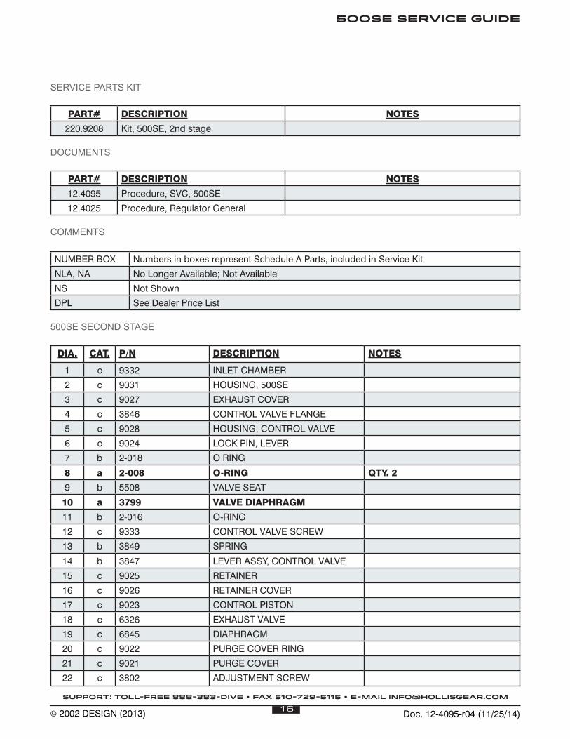
SERVICE PARTS KIT
PART# DESCRIPTION NOTES
220.9208 Kit, 500SE, 2nd stage
DOCUMENTS
PART# DESCRIPTION NOTES
12.4095 Procedure, SVC, 500SE
12.4025 Procedure, Regulator General
COMMENTS
NUMBER BOX Numbers in boxes represent Schedule A Parts, included in Service Kit
NLA, NA No Longer Available; Not Available
NS Not Shown
DPL See Dealer Price List
500SE SECOND STAGE
DIA. CAT. P/N DESCRIPTION NOTES
1 c 9332 INLET CHAMBER
2 c 9031 HOUSING, 500SE
3 c 9027 EXHAUST COVER
4 c 3846 CONTROL VALVE FLANGE
5 c 9028 HOUSING, CONTROL VALVE
6 c 9024 LOCK PIN, LEVER
7 b 2-018 O RING
8 a 2-008 O-RING QTY. 2
9 b 5508 VALVE SEAT
10 a 3799 VALVE DIAPHRAGM
11 b 2-016 O-RING
12 c 9333 CONTROL VALVE SCREW
13 b 3849 SPRING
14 b 3847 LEVER ASSY, CONTROL VALVE
15 c 9025 RETAINER
16 c 9026 RETAINER COVER
17 c 9023 CONTROL PISTON
18 c 6326 EXHAUST VALVE
19 c 6845 DIAPHRAGM
20 c 9022 PURGE COVER RING
21 c 9021 PURGE COVER
22 c 3802 ADJUSTMENT SCREW
Doc. 12-4095-r04 (11/25/14)17
500SE SERVICE GUIDE
SUPPORT: TOLL-FREE 888-383-DIVE • FAX 510-729-5115 • E-MAIL [email protected]
© 2002 DESIGN (2013)
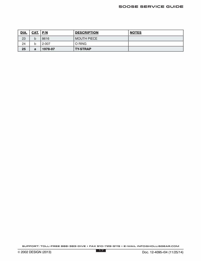
DIA. CAT. P/N DESCRIPTION NOTES
23 b 8616 MOUTH PIECE
24 b 2-007 O RING
25 a 1978-07 TY-STRAP