5096 data transmitter operating and programming manualhydrolynx.com/manuals/5096dt.pdf · except by...
TRANSCRIPT

5096Data Transmitter
Operating andProgramming
Manual
A102747-12

5096 Data Transmitter HydroLynx Systems, Inc.
Page 2 A102747
Receiving and UnpackingCarefully unpack all components and compare to the packing list. Notify HydroLynxSystems immediately concerning any discrepancy. Inspect equipment to detect anydamage that may have occurred during shipment. In the event of damage, any claim forloss must be filed immediately with the carrier by the consignee. If the equipment wasshipped via Parcel Post or UPS, contact HydroLynx Systems for instructions.
ReturnsIf equipment is to be returned to the factory for any reason, call HydroLynx between8:00 a.m. and 4:00 p.m. Pacific Time to request a Return Authorization Number (RA#).Include with the returned equipment a description of the problem and the name, address,and daytime phone number of the sender. Carefully pack the equipment to preventdamage during the return shipment. Call HydroLynx for packing instructions in the caseof delicate or sensitive items. If packing facilities are not available, take the equipment tothe nearest Post Office, UPS, or other freight service and obtain assistance withpackaging. Please write the RA# on the outside of the box.
WarrantyHydroLynx Systems warrants that its products are free from defects in material andworkmanship under normal use and service for a period of one year from the date ofshipment from the factory. HydroLynx Systems' obligations under this warranty are limitedto, at HydroLynx's option: (I) replacing; or (ii) repairing; any product determined to bedefective. In no case shall HydroLynx Systems' liability exceed product's original purchaseprice. This warranty does not apply to any equipment that has been repaired or altered,except by HydroLynx Systems, or that has been subjected to misuse, negligence, oraccident. It is expressly agreed that this warranty will be in lieu of all warranties of fitnessand in lieu of the warranty of merchantability.
AddressHydroLynx Systems, Inc.950 Riverside Pkwy., Suite 10West Sacramento, CA 95605Phone: (916) 374-1800Fax: (916) 374-1877E-mail: [email protected]
Copyright © 2005 HydroLynx Systems, Inc.

HydroLynx Systems, Inc. 5096 Data Transmitter
A102747 Page 3
Table of Contents
1 Introduction 91.1 Organization of the Manual 101.2 Description of the 5096 Data Transmitter 11
1.2.1 Programmable Features 111.2.2 Other Features 12
1.3 Specifications for the 9601 Board 131.4 Specifications for the 5096 151.5 Specifications for the 5096N 16
2 Setup and Installation 172.1 Introduction to Software Set Up 18
2.1.1 Operator's Console Set Up 182.1.2 Station ID Switches 192.1.3 Initial Parameter Set Up 202.1.4 After Installation Testing and Maintenance 212.1.5 Down Load Logged Data 222.1.6 Sensor Set Up Examples 24
Sensor Set Up: EVENT Sensors 245050P, 5050P-MS Tipping Bucket 252500, 2501 Two Wire Precipitation Gage 255096ELFT Float Type Sensor 26Absolute Encoder Sensor 28
Sensor Set Up: ANALOG Sensors 292048RH/T Relative Humidity and Temperature 295050LLPTK Pressure Transducer 331522 Barometric Pressure 36Battery Sensor 39
Sensor Set Up: WIND Sensors 405050WS/WD Wind Speed and Direction 40
Sensor Set Up: PEAK WIND Sensors 44Sensor Set Up: STATUS Sensor 46
5096ES Emergency Status Sensor 46Sensor Set Up: SERIAL Sensor 49

5096 Data Transmitter HydroLynx Systems, Inc.
Page 4 A102747
Table of Contents
2 Setup and Installation (continued)2.2 Hardware Installation 50
2.2.1 Console Cable Connection 502.2.2 5050LLFT and 5050TS Modifications 502.2.3 Radio Transmitter Check 512.2.4 Antenna Connection 512.2.5 Battery Connection 512.2.6 Solar Panel or AC Charger Connection 512.2.7 Sensor Connectors 522.2.8 Data Transmitter Installation 52
3 Hardware Inputs and Outputs 533.1 Hardware Introduction 543.2 Sensor Inputs 55
3.2.1 Digital Inputs 553.2.2 Analog Inputs 563.2.3 Virtual Inputs 573.2.4 Serial Sensor Interface 57
3.3 Board Features 583.3.1 Switches 583.3.2 LEDS 603.3.3 Test Points 613.3.4 Internal Battery Jumper 62
3.4 Communication Outputs 633.4.1 Telemetry Interface 633.4.2 Console Interface 63

HydroLynx Systems, Inc. 5096 Data Transmitter
A102747 Page 5
Table of Contents
4 Programming 654.1 Introduction 674.2 Firmware Version 674.3 Rules for Entering Commands 684.4 Battery Protected Parameters 694.5 Command Help Facilities 694.6 Command Examples 704.7 Command Descriptions 71
AD-OFF 72AD-ON 73ALIGN 74CHK-MEM 75CLEAR-MEM 76GET-MEM 77HELP 80INIT 81READ-AN 82READ-BATT 83READ-CTR 84READ-EV 85READ-IDSW 86READ-PK 87READ-SERIAL 88READ-ST 89READ-WI 90RESET 91RESETCNT 92RESETINIT 93SET-AN 94SET-BATT 95SET-BAUD 96SET-CTR 97SET-CTRRESET 98SET-ENH 99SET-EV 100

5096 Data Transmitter HydroLynx Systems, Inc.
Page 6 A102747
Table of Contents
4 Programming (continued)SET-EVRESET 101SET-HOLDOFF 102SET-MEM 103SET-PK 104SET-RFWARM 105SET-SERIAL 108SET-SPT 109SET-ST 110SET-WARM 111SET-WI 112SHOWALL 113TEST 114TEST-TX 115TIME-MODE 116TIME= 117WRITE-CTR 118WRITE-EV 119WRITE-SERIAL 120
4.8 Parameter Descriptions 1214.9 Error Messages 135

HydroLynx Systems, Inc. 5096 Data Transmitter
A102747 Page 7
Table of Contents
5 Maintenance, Testing and Troubleshooting 1375.1 Maintenance 138
5.1.1 Station Check 1385.1.2 Battery 1385.1.3 Silica Gel 1385.1.4 Sensor Maintenance 1395.1.5 Radio Maintenance 139
5.2 Testing 1405.2.1 Power-up Test 1405.2.2 Level 1 Test 1405.2.3 Level 2 Test 1415.2.4 Level 3 Test 142
5.3 Troubleshooting 1435.3.1 Battery Failures 1435.3.2 Sensor Failures 1445.3.3 Transmission Failures 144
5.4 Troubleshooting with the Console 1455.4.1 TEST Sequence 1455.4.2 READ-BATT Command 1455.4.3 READ Commands 1465.4.4 GET-MEM and Time of Failure 1465.4.5 SHOWALL Command 1465.4.6 SET Commands 1465.4.7 Signal Input Protection 1465.4.8 Tipping Bucket and Transmitter 1465.4.9 ANALOG Sensors 1475.4.10 SET-WARM and ANALOG Sensors 1475.4.11 RFWARM and the Transmitter 1475.4.12 RESETCNT Command 1485.4.13 INIT and Default Settings 148
5096 Data Transmitter HydroLynx Systems, Inc.
Page 8 A102747
Table of Contents
6 Appendix 1496.1 Programming summary 150
6.1.1 Alphabetically List of Commands 1506.1.2 Functional Grouping of Commands 1516.1.3 Parameter Descriptions 152
6.2 Drawings 154AC107897 509681 With Status Connector 155AC104045 5096 Wire Diagram 156AC107911 Wiring Diagram, Typical Sensors to 5096N 157AC107908 T9601 PCB Assembly Diagram 158AC104974 Interconnect PCB All Season Power to Pin B 159AC104020 Console RS232 Cable, 9 Pin to 9 Pin 160AC104180 Outline, Pin Outs for Interconnect Circuit Board 161A104973 Maintenance Report 162A101229-2 Sensor Set Up Checklist 163A101018-4 Test Results Report 164AC107484 Transmission Formats 165
6.3 5096 Firmware Enhancements 167A101100 5096 Firmware Enhancements Version 3.0 168A101101 5096 Firmware Enhancements Version 3.1 169A101102 5096 Firmware Enhancements Version 3.2 170A101103 5096 Firmware Enhancements Version 3.3 171A101104 5096 Firmware Enhancements Version 4.0 172A101105 5096 Firmware Enhancements Version 3.4 173A101106 5096 Firmware Enhancements Version 3.5 174A101107 5096 Firmware Enhancements Version 3.6 175A101108 5096 Firmware Enhancements Version 3.7 176A100740 5096 Firmware Enhancements Version 3.8 177A100741 5096 Firmware Enhancements Version 3.9 178A100742 5096 Firmware Enhancements Version 4.1 179A100743 5096 Firmware Enhancements Version 4.2 180A100744 5096 Firmware Enhancements Version 4.3 181A100745 5096 Firmware Enhancements Version 4.4 182

HydroLynx Systems, Inc. 5096 Data Transmitter
A102747 Page 9
1 Introduction
1.1 Organization of the Manual 10
1.2 Description of the 5096 Data Transmitter 111.2.1 Programmable Features 111.2.2 Other Features 12
1.3 Specifications for the 9601 Board 13
1.4 Specifications for the 5096 15
1.5 Specifications for the 5096N 16

5096 Data Transmitter HydroLynx Systems, Inc.
Page 10 A102747
1.1 Organization of the Manual
This manual describes the HydroLynx Systems ALERT Data Transmitter Model 5096.There are six sections of the manual containing information related to a specific functionor aspect of the 5096 Data Transmitter:
Introduction
The Introduction describes the manual organization to help the reader inunderstanding how the information is presented. It also provides a generaldescription of the 5096 Data Transmitter and the data transmitter specifications.
Set Up and Installation
This section contains the information needed for the initial set up of the systemsoftware and hardware installation. It provides instructions on how to set up theuser's personal computer for use with the 5096 Data Transmitter. Also provided areinstructions for the 5096 Data Transmitter software set up, hardware installation,wiring, and power connections.
Hardware Inputs and Outputs
This section describes the sensor inputs, the Data Transmitter board features andCommunication outputs.
Programming
This section describes how to program the 5096 Data Transmitter. It also lists the5096 Data Transmitter software commands and their parameters in detail.
Maintenance, Testing and Troubleshooting
This section provides information to help the user in locating and resolvingproblems often encountered during initial system start-up. It also provides themaintenance requirements for maximizing the life and operating cycle of the 5096Data Transmitter.
Appendix
This section provides listings of programming commands, command functionalgroupings and command parameters. It also provides assembly and wiringdiagrams, and reports to help in the installation, use, and repair of the 5096 DataTransmitter.

HydroLynx Systems, Inc. 5096 Data Transmitter
A102747 Page 11
1.2 Description of the 5096 Data Transmitter
The 5096 Data Transmitter collects, processes, and transmits analog, digital and serialinterface sensor data on events and timed intervals. The collection, processing andtransmission of sensor data is controlled by parameters that are easily programmed usinga terminal or computer with standard communications software. Communications with the5096 is through an RS232 port with a programmable baud rate.
Real-time data is transmitted by radio using ALERT formats.
The 5096 Data Transmitter features on board data logging capabilities. Data can be downloaded using a portable computer during on-site visits.
1.2.1 Programmable Features
System Commands
! Set the system time and time mode (Elapsed or Real time)! Set the clock tick interval! Set the analog sensor warmup time! Align sensor sample and transmit timers! Initialize parameters! Reset the transmitter
Communication Set Up Commands
! Set the serial port baud rate! Set the RF warm, preamble, carrier detect wait and power state and power on times! Set the transmitter hold-off time! Select standard or enhanced ALERT transmission formats
Sensor Set Up Commands
! Set the sensor modes! Set the sample and transmit time intervals! Set the change required to transmit events and alarms! Set the calibration coefficients! Set the sensor ID! Read and display raw and calibrated sensor values! Set counter sensor values and reset times
5096 Data Transmitter HydroLynx Systems, Inc.
Page 12 A102747
Data Logging Commands
! Enable or disable data logging! Select logging memory full action! Display logged data! Show logging memory usage! Clear logging memory
Test and Maintenance Commands
! Test command to perform level 1 or 2 test! Read sensor values! Initiate RF transmission with and without tone! Control analog power! Display and clear Reset counter
1.2.2 Other Features
Low Power, Battery Operated
! Uses low power CMOS circuitry! Power down mode for low power consumption during stand-by! Optional solar panel or AC charger to maintain battery voltage
Real-time Data Transmission
! Real-time data is sent to the central site computer for immediate processing! Transmission can be generated by an event or timed interval! Alarm transmissions send double reports and override transmit hold-off timer! ALERT ASCII, Binary, Enhanced ALERT and Enhanced IFLOWS formats supported! Combined wind run and direction in ALERT wind format supported
Data Logging
! Sensor data reports are logged in battery-backed memory! Logged data can be down loaded into a portable computer on site! Allows for stand-alone data logging or as a backup for transmitted data! Up to 4000 event data points or 12000 timed data points are logged
HydroLynx Systems, Inc. 5096 Data Transmitter
A102747 Page 13
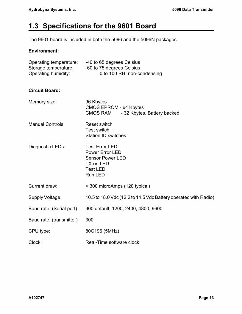
1.3 Specifications for the 9601 Board
The 9601 board is included in both the 5096 and the 5096N packages.
Environment:
Operating temperature: -40 to 65 degrees CelsiusStorage temperature: -60 to 75 degrees CelsiusOperating humidity: 0 to 100 RH, non-condensing
Circuit Board:
Memory size: 96 KbytesCMOS EPROM - 64 KbytesCMOS RAM - 32 Kbytes, Battery backed
Manual Controls: Reset switchTest switchStation ID switches
Diagnostic LEDs: Test Error LEDPower Error LEDSensor Power LEDTX-on LEDTest LEDRun LED
Current draw: < 300 microAmps (120 typical)
Supply Voltage: 10.5 to 18.0 Vdc (12.2 to 14.5 Vdc Battery operated with Radio)
Baud rate: (Serial port) 300 default, 1200, 2400, 4800, 9600
Baud rate: (transmitter) 300
CPU type: 80C196 (5MHz)
Clock: Real-Time software clock

5096 Data Transmitter HydroLynx Systems, Inc.
Page 14 A102747
Digital Inputs
4 digital channels with up to 100 event triggers/second2 channels: up/down accumulator2 channels: up only accumulator with pre-divide counterProgrammable: Enable/disable event status
ALERT wind format (up only) - wind run and directionIncrement/decrement mode (up/down only)Pre-divide counter (up only)Transmit time interval (no change required to transmit)Change required to transmit an eventChange required to transmit an alarmCalibration coefficientsAccumulator reset timeSensor ID
1 digital channel with 8 status (binary inputs)Programmable: Sample time interval
Transmit time interval (no change required to transmit)Enable transmission of zerosStatus change (any or all) to transmit a sampleStatus change (any or all) to transmit an alarmSensor ID
Analog Inputs
8 analog channels (10 bit resolution with +/- 0.24% non-linearity error)7 channels (0-5 VDC)1 channel (battery voltage)4 Supply voltages: Vbatt (12 VDC nominal) non-switched
+5 VDC non-switchedVsw (12 VDC nominal) switchedVref (+5 VDC) switched
Programmable: Event threshold (no sample transmission until thresholdreached)Transmit time interval (no change required)Sample time intervalChange required to transmit a sampleChange required to transmit an alarmCalibration coefficientsSensor ID
Serial Inputs
8 serial channels to report data set by the WRITE-SERIAL command.
HydroLynx Systems, Inc. 5096 Data Transmitter
A102747 Page 15
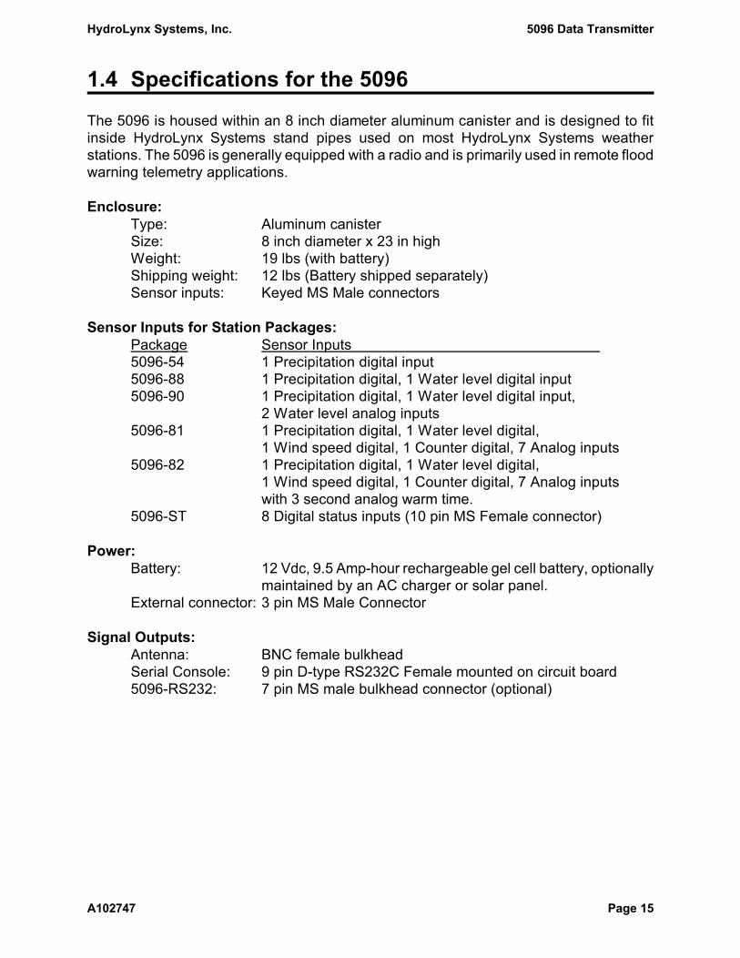
1.4 Specifications for the 5096
The 5096 is housed within an 8 inch diameter aluminum canister and is designed to fitinside HydroLynx Systems stand pipes used on most HydroLynx Systems weatherstations. The 5096 is generally equipped with a radio and is primarily used in remote floodwarning telemetry applications.
Enclosure:Type: Aluminum canisterSize: 8 inch diameter x 23 in highWeight: 19 lbs (with battery)Shipping weight: 12 lbs (Battery shipped separately)Sensor inputs: Keyed MS Male connectors
Sensor Inputs for Station Packages:Package Sensor Inputs 5096-54 1 Precipitation digital input5096-88 1 Precipitation digital, 1 Water level digital input5096-90 1 Precipitation digital, 1 Water level digital input,
2 Water level analog inputs5096-81 1 Precipitation digital, 1 Water level digital,
1 Wind speed digital, 1 Counter digital, 7 Analog inputs5096-82 1 Precipitation digital, 1 Water level digital,
1 Wind speed digital, 1 Counter digital, 7 Analog inputswith 3 second analog warm time.
5096-ST 8 Digital status inputs (10 pin MS Female connector)
Power:Battery: 12 Vdc, 9.5 Amp-hour rechargeable gel cell battery, optionally
maintained by an AC charger or solar panel.External connector: 3 pin MS Male Connector
Signal Outputs:Antenna: BNC female bulkheadSerial Console: 9 pin D-type RS232C Female mounted on circuit board5096-RS232: 7 pin MS male bulkhead connector (optional)

5096 Data Transmitter HydroLynx Systems, Inc.
Page 16 A102747
1.5 Specifications for the 5096N
The 5096N is the 5096 circuit board mounted into a NEMA type 4X fiberglass enclosure.The 5096N is designed for outdoor mounting onto a panel or a mast. The 5096N can beequipped with a radio and used as part of a telemetry system, or it can be used as a datalogger.
Enclosure:Type: NEMA type 4X fiberglassSize: 15 ½" X 13 ½" X 6 ½" NEMA enclosure Type 4X Weight: 16 lb (with battery)Shipping weight: 12 lbs (Battery shipped separately)Sensor inputs: Case is provided with 7 cable strain reliefs.
Sensor Inputs for Station Package:Connections: Screw Terminal Interconnect PCB.
Package Sensor Inputs 5096-N 4 digital, 7 analog, and 8 digital status inputs. 5096-S 4 digital, 7 analog, and 8 digital status inputs,
8 serial inputs.
Power:Battery: 12 Vdc, 7 Amp-hour rechargeable gel cell battery, optionally
maintained by an AC charger or solar panel.External connector: 3 pin MS Male Connector
Signal Outputs:Antenna: N-type female lightning arresterSerial Console: 9 pin D-type RS232C Female mounted on circuit board5096-RS232: 7 pin MS male bulkhead connector (optional)

HydroLynx Systems, Inc. 5096 Data Transmitter
A102747 Page 17
2 Set Up and Installation
2.1 Introduction to Software Set Up 182.1.1 Operator's Console Set Up 182.1.2 Station ID Switches 192.1.3 Initial Parameter Set Up 202.1.4 After Installation Testing and Maintenance 212.1.5 Down Load Logged Data 222.1.6 Sensor Set Up Examples 24
Sensor Set Up: EVENT Sensors 245050P, 5050P-MS Tipping Bucket 252500, 2501 Two Wire Precipitation Gage 255096ELFT Float Type Sensor 26Absolute Encoder Sensor 28
Sensor Set Up: ANALOG Sensors 292048RH/T Relative Humidity and Temperature 295050LLPTK Pressure Transducer 331522 Barometric Pressure 36Battery Sensor 39
Sensor Set Up: WIND Sensors 405050WS/WD Wind Speed and Direction 40
Sensor Set Up: PEAK WIND Sensors 44Sensor Set Up: STATUS Sensor 46
5096ES Emergency Status Sensor 46Sensor Set Up: SERIAL Sensor 49
2.2 Hardware Installation 502.2.1 Console Cable Connection 502.2.2 5050LLFT and 5050TS Modifications 502.2.3 Radio Transmitter Check 512.2.4 Antenna Connection 512.2.5 Battery Connection 512.2.6 Solar Panel or AC Charger Connection 512.2.7 Sensor Connectors 522.2.8 Data Transmitter Installation 52

5096 Data Transmitter HydroLynx Systems, Inc.
Page 18 A102747
2.1 Introduction to Software Set Up
This section describes the initial steps to set up your 5096 Data Transmitter programmablefeatures. This includes console set up and communication verification, station ID set up,system and sensor parameter set up, and data logging set up.
Also included in this section are the commands used after installation for testing andmaintenance, and logged data retrieval.
2.1.1 Operator's Console Set Up
The operator's console is the primary means for communicating with the 5096 DataTransmitter. From the console, the operator can display, modify and log to disk all systemparameters. Data stored in the 5096 Data Transmitter logging memory can be downloaded, displayed and logged to disk on the console.
The console can be a palmtop, notebook or desktop computer which uses HydroLynxSystems 5073PT Palmtop 5096 Programming Software, Microsoft Windows Terminalsoftware, Microsoft HyperTerminal software, or any other terminal emulation software. Aserial ASCII terminal can be used in place of a personal computer.
The console is connected to the 5096 Data Transmitter RS232 port, J5, with a customserial cable such as HydroLynx Systems Model 5071C-5096. See the Console RS232cable, 9 Pin to 9 Pin drawing AC104020 in Section 6.2.
The default baud rate used by the 5096 is 300 baud for all EPROM types except S. Thedefault baud rate for EPROM type S is 9600 baud. The baud rate may be changed on the5096 by command after communication with the 5096 has been established. The baud ratemust then be changed on the console to match that of the 5096. See the commandSET-BAUD in Section 4.7.
In addition to the baud rate the following RS-232 protocol settings must be used:No Parity Full duplex (FDX) for version 3 firmware8 Data bits Half duplex (HDX) for version 4 firmware1 Stop bit
To start communication with the 5096 Data Transmitter from your computer console:
1. Start the communication software on your console computer.
2. Connect your console computer to the 5096 Data Transmitter RS232 port, J5. If the5096 Data Transmitter is powered up, the RUN LED will turn on.
3. Verify the proper communication baud rate for your communication software.
4A. 5096 Data Transmitter was off.

HydroLynx Systems, Inc. 5096 Data Transmitter
A102747 Page 19
Power-up the 5096 Data Transmitter. The 5096 will follow its power up sequencechecks, display the HydroLynx Systems copyright, the firmware part number,version number, release date and then display the > prompt.
4B. 5096 Data Transmitter was already on.Press the [Enter] key and the 5096 should display the > prompt.
If you do not get the 5096 > prompt:
1. Check all connections.Is your cable connected securely to both the 5096 Data Transmitter RS232 port, J5and the console serial port?
2. Check for connection to proper console serial port.Is you cable connected to the serial port set for your communication software(COM1, COM2, ...)?
3. Check serial communication parameters.Is your communication software set to 300 baud, No parity, 8 Data bits, 1 Stop bit?It is it, try using another baud rate in case someone left the 5096 baud rate set tosomething other than the default, e.g. 9600.
4. Check your cable.Are you using the correct type of cable? The HydroLynx Systems cable5071C-5096 will cause the 5096 to turn on the RUN LED when it is connected tothe 5096 RS232 port, J5 regardless of whether or not it is connected to the consolecorrectly. Disconnect the cable from your console and check if the RUN LED comeson. If it does, replace your cable.
5. Check your power, Level 1 test.When you power up the 5096 Data Transmitter it will perform its power upsequence checks which turn on and off LEDs (see Section 5.2.1). If this power upsequence does not occur, check your power.
6. Check your sensors.Damaged or incorrect sensors or sensor connections can effect proper 5096 DataTransmitter performance. Disconnect all sensors and try again.
2.1.2 Station ID Switches
Check to see that the ID switches are set to the correct station ID number. The default IDnumbers for sensors are based on the station ID number.
The station ID is set in the ID switches with the least significant digit (ones) in switch ID0and the highest significant digit (thousands) in switch ID3.
5096 Data Transmitter HydroLynx Systems, Inc.
Page 20 A102747
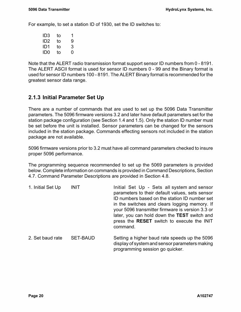
For example, to set a station ID of 1930, set the ID switches to:
ID3 to 1ID2 to 9ID1 to 3ID0 to 0
Note that the ALERT radio transmission format support sensor ID numbers from 0 - 8191.The ALERT ASCII format is used for sensor ID numbers 0 - 99 and the Binary format isused for sensor ID numbers 100 - 8191. The ALERT Binary format is recommended for thegreatest sensor data range.
2.1.3 Initial Parameter Set Up
There are a number of commands that are used to set up the 5096 Data Transmitterparameters. The 5096 firmware versions 3.2 and later have default parameters set for thestation package configuration (see Section 1.4 and 1.5). Only the station ID number mustbe set before the unit is installed. Sensor parameters can be changed for the sensorsincluded in the station package. Commands effecting sensors not included in the stationpackage are not available.
5096 firmware versions prior to 3.2 must have all command parameters checked to insureproper 5096 performance.
The programming sequence recommended to set up the 5069 parameters is providedbelow. Complete information on commands is provided in Command Descriptions, Section4.7. Command Parameter Descriptions are provided in Section 4.8.
1. Initial Set Up INIT Initial Set Up - Sets all system and sensorparameters to their default values, sets sensorID numbers based on the station ID number setin the switches and clears logging memory. Ifyour 5096 transmitter firmware is version 3.3 orlater, you can hold down the TEST switch andpress the RESET switch to execute the INITcommand.
2. Set baud rate SET-BAUD Setting a higher baud rate speeds up the 5096display of systemand sensor parameters makingprogramming session go quicker.

HydroLynx Systems, Inc. 5096 Data Transmitter
A102747 Page 21
3. System Set Up SHOWALL Display current system parameters.SET-HOLDOFF Set the transmitter hold-off timer.SET-RFWARM Set the RF tx warm, preamble, carrier detect wait
time, wait radio power state, and power on time.You may have to increase the RF warm time forsystems that use repeaters that are not the storeand forward type. You will have to increase theRF power on time if you switch from a crystal toa synthesized radio without changing firmware.
SET-ENH Select the ALERT transmission format.SET-SPT Set the clock time step.RESETINIT Disable when reprogramming 5096 parameters.
4. Sensor Set Up SET-AN Program ANALOG sensors.SET-WARM Set the ANALOG warm time.SET-BATT Program the BATTERY sensor.SET-EV Program EVENT sensors.SET-EVRESET Program EVENT sensor reset time.SET-CTR Program COUNTER sensors.SET-CTRRESET Program COUNTER sensor reset time.SET-WI Program WIND sensors.SET-PK Program PEAK WIND sensors.SET-ST Program the STATUS sensor.SET-SERIAL Program SERIAL sensors.WRITE-EV Write EVENT sensor values.WRITE-CTR Write COUNTER sensor values.WRITE-SERIAL Write SERIAL sensor values.ALIGN Aligns all timers.
5. Logging Set Up SET-MEM Enable data logging and overwriting when full.TIME-MODE Set the time mode.TIME= Set the transmitter time.CLEAR-MEM Clear data logging memory.
2.1.4 After Installation Testing and Maintenance
1. Check sensors READ-AN Read ANALOG sensor values.READ-EV Read EVENT sensor accumulator values.READ-BATT Read the BATTERY voltage.READ_IDSW Read the Station ID switches.
2. Down load data SET-BAUD Set data transfer rate.TIME= Check the transmitter time.GET-MEM Down load data to console.CLEAR-MEM Clear data logging memory.

5096 Data Transmitter HydroLynx Systems, Inc.
Page 22 A102747
2.1.5 Down Load Logged Data
When visiting the site for any reason, make entries in your notebook's Data Sheetsdescribing the purpose of the visit and everything done. An example Maintenance Reportis provided in Section 6.2.
Down load data from the 5096 Data Transmitter using the GET-MEM command beforeclearing the memory, or changing any parameters or replacing the battery (see Section2.2.5). The READ command will show the current sensor values, not the logged data.
Connect the console to the 5096 and verify communication as described in Section 2.1.1.
1. Set baud rate SET-BAUD Setting a higher baud rate speeds up the 5096display of logged data making the retrievalsession go quicker.
2. Verify time TIME-MODE Verify the time mode, Real or Elapsed Time.TIME= Verify the current transmitter time. You may want
to adjust the logged data report times for anytime error.
3. Verify readings READ-... Verify correct calibrated readings for sensors.You may want to adjust the logged data reportvalues for any data reading errors.
4. Start logging Start logging on the console using the commandsequence required for your software.
HydroLynx 5073PT Palmtop software On the File menu pull-down select CaptureText... and enter a file name.
Microsoft Windows Terminal software On the Transfer menu pull-down select ReceiveText File... and enter a file name.
Microsoft HyperTerminal software On the Transfer menu pull-down, select CaptureText... and enter a file name.
Enter a filename in which to store the loggeddata reports as they are displayed. Use a .txt fileextension to simplify viewing the file later underMicrosoft Windows. Enter filename that indicatesthe station and data retrieval time (month). Forexample at the Bigcreek gauge in April, create afile 'bigcreek-apr.txt'.

HydroLynx Systems, Inc. 5096 Data Transmitter
A102747 Page 23
5A. Down load all GET-MEM Down load data from the 5096. All logged datareports are logged to the file as they aredisplayed. Logged data display starts with theoldest report logged.
5B. Down load ID GET-MEM id Down load data for one sensor by entering thesensor ID number after the GET-MEM command.
5C. Down load period GET-MEM ,h1,.. Down load data for a time period by entering thestart and end time after the GET-MEMcommand. The start time is entered as:
h1,m1,YYY1,M1,D1,and the end time is entered as:
h2,m2,YYY2,M2,D2If no sensor ID is entered, all sensor data for thetime period is down loaded.
6. Stop logging Stop logging.
HydroLynx 5073PT Palmtop software On the File menu pull-down select CaptureText... and when asked to Cancel Capture Text?,answer tap Yes.
Microsoft Windows Terminal software On the Transfer menu pull-down select Stop.
Microsoft HyperTerminal software On the Transfer menu pull-down, select CaptureText... and Stop.
7. Review file Display the contents of the logging file to verifythat data was down loaded correctly.
8. Clear memory CLEAR-MEM Clear the 5096 logging memory.
9. Change set up SET-... Change sensor parameters if necessary.WRITE-... Set accumulator values to new correct values if
necessary.ALIGN Align sensor timers if any changed.CLEAR-MEM Clear the 5096 logging memory again after
aligning parameters.

5096 Data Transmitter HydroLynx Systems, Inc.
Page 24 A102747
2.1.6 Sensor Set Up Examples
Version 3.2 and later have default sensor parameters set for standard data collectionrequirements. However, special data collection requirements or sensor configurations willrequire sensor parameter changes.
The 5096 Data Transmitter transmits data reports when an event occurs and/or on timedintervals. An event occurs when a digital sensor triggers a change in its accumulator value.A timed interval is a programmable timer which triggers a sensor reading and/or a datareport transmission.
The 5096 Data Transmitter reads raw (RAW) sensor values, calibrates the values usingsensor calibration coefficients and transmits the calculated (CAL) data to the central site.Sensor calibration coefficients can be used to calculate CAL data in engineering units.Both the RAW and CAL data values are integers (no decimal point).
The central site computer stores the transmitted CAL data in its database and converts theCAL data into engineering units (decimal points included).
An important consideration in calibrating sensor data on the 5096 Data Transmitter is thatthe ALERT transmission format limits data values to 11 bits. This limits the data reports tovalues of 0 to 2047. A number greater than 2047 only has its lower 11 bits transmitted. Forexample, 2049 is transmitted as 1. A number less than 0 is transmitted as 2048 plus thenegative number. For example, -1 is transmitted as 2047.
Before changing station or sensor parameters, record the current parameters. Use theSHOWALL command to display all parameters and the console software to log to a diskfile. Refer to Section 2.1.5 for information on logging to disk files.
Complete descriptions of commands and parameters is provided in Sections 4.7 and 4.8.
Sensor Set Up: EVENT Sensors
When an EVENT sensor triggers an event its RAW accumulator is incremented ordecremented. CAL data is calculated from the RAW accumulator using sensor calibrationcoefficients when the Event Detection flag is ENABLED and change criteria is met. Thechange criteria is met when the difference between the newly calculated CAL data and thelast transmitted CAL data is equal to or greater than the Change for Alarm or Change toTxmit parameters.
EVENT sensor data is transmitted on the time interval set in the Transmit Intervlparameter. The Transmit Intervl parameter units are in seconds. Timed reports are nottransmitted when this parameter is zero.
HydroLynx Systems, Inc. 5096 Data Transmitter
A102747 Page 25
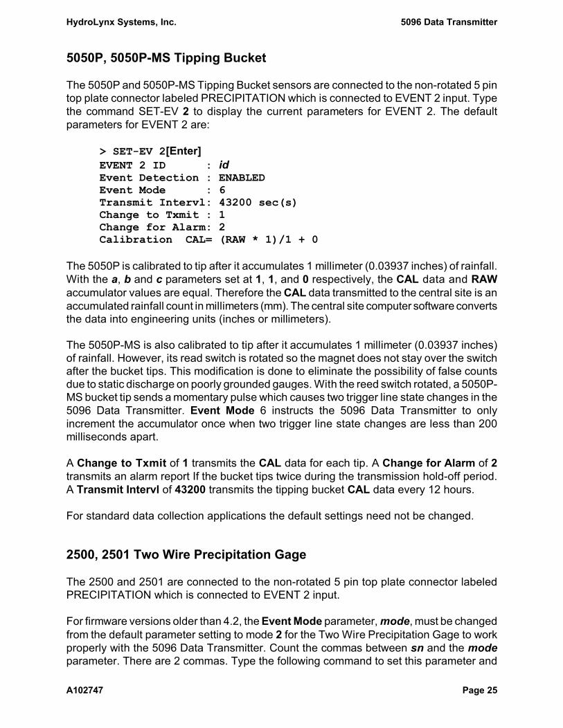
5050P, 5050P-MS Tipping Bucket
The 5050P and 5050P-MS Tipping Bucket sensors are connected to the non-rotated 5 pintop plate connector labeled PRECIPITATION which is connected to EVENT 2 input. Typethe command SET-EV 2 to display the current parameters for EVENT 2. The defaultparameters for EVENT 2 are:
> SET-EV 2[Enter]EVENT 2 ID : idEvent Detection : ENABLEDEvent Mode : 6Transmit Intervl: 43200 sec(s)Change to Txmit : 1Change for Alarm: 2Calibration CAL= (RAW * 1)/1 + 0
The 5050P is calibrated to tip after it accumulates 1 millimeter (0.03937 inches) of rainfall.With the a, b and c parameters set at 1, 1, and 0 respectively, the CAL data and RAWaccumulator values are equal. Therefore the CAL data transmitted to the central site is anaccumulated rainfall count in millimeters (mm). The central site computer software convertsthe data into engineering units (inches or millimeters).
The 5050P-MS is also calibrated to tip after it accumulates 1 millimeter (0.03937 inches)of rainfall. However, its read switch is rotated so the magnet does not stay over the switchafter the bucket tips. This modification is done to eliminate the possibility of false countsdue to static discharge on poorly grounded gauges. With the reed switch rotated, a 5050P-MS bucket tip sends a momentary pulse which causes two trigger line state changes in the5096 Data Transmitter. Event Mode 6 instructs the 5096 Data Transmitter to onlyincrement the accumulator once when two trigger line state changes are less than 200milliseconds apart.
A Change to Txmit of 1 transmits the CAL data for each tip. A Change for Alarm of 2transmits an alarm report If the bucket tips twice during the transmission hold-off period.A Transmit Intervl of 43200 transmits the tipping bucket CAL data every 12 hours.
For standard data collection applications the default settings need not be changed.
2500, 2501 Two Wire Precipitation Gage
The 2500 and 2501 are connected to the non-rotated 5 pin top plate connector labeledPRECIPITATION which is connected to EVENT 2 input.
For firmware versions older than 4.2, the Event Mode parameter, mode, must be changedfrom the default parameter setting to mode 2 for the Two Wire Precipitation Gage to workproperly with the 5096 Data Transmitter. Count the commas between sn and the modeparameter. There are 2 commas. Type the following command to set this parameter and

5096 Data Transmitter HydroLynx Systems, Inc.
Page 26 A102747
you will get the response:
> SET-EV 2,,2[Enter]EVENT 2 ID : idEvent Detection : ENABLEDEvent Mode : 2Transmit Intervl: 43200 sec(s)Change to Txmit : 1Change for Alarm: 2Calibration CAL= (RAW * 1)/1 + 0
The 2500 and 2501 are calibrated to increment the EVENT 2 accumulator for each .01inches or rainfall. The 2500M and 2501M are calibrated to increment the EVENT 2accumulator for each millimeter of rainfall. For standard data collection applications noother parameter changes are required.
5096ELFT Float Type Sensor
The 5096ELFT Float Type Sensor is connected to the rotated 5 pin top plate connectorlabeled DIGITAL which is connected to EVENT 1 input. Type the command SET-EV 1 todisplay the current parameters for EVENT 1. The default parameters for EVENT 1 are:
5096-81, 88, 90 5096N > SET-EV 1[Enter]EVENT 1 ID : id idEvent Detection : ENABLED DISABLEDEvent Mode : 4 4Transmit Intervl: 0 sec(s) 0 sec(s)Change to Txmit : 1 1Change for Alarm: 10 10Calibration CAL= (RAW * 1)/1 + 0 (RAW * 1)/1 + 0
Changes to the EVENT 1 parameters are made with the SET-EV command. First type thecommand SET-EV with a question mark to get the command parameter list:
> SET-EV ?[Enter]SET-EV sn,{en_ev},{mode},{t_int},{cgt},{cga},{a},{b},{c},{id}
To enable Event Detection on the EVENT 1 sensor set the en_ev parameter to 1. Typethe following command to set this parameter and you will get the response:
> SET-EV 1,1[Enter]EVENT 1 ID : idEvent Detection : ENABLEDEvent Mode : 4Transmit Intervl: 0 sec(s)

HydroLynx Systems, Inc. 5096 Data Transmitter
A102747 Page 27
Change to Txmit : 1Change for Alarm: 10Calibration CAL= (RAW * 1)/1 + 0
The standard 5096ELFT has 6 reed switches and a 375 millimeter (mm) pulley makingeach increment or decrement a 5mm (0.016405 feet) change in level. Each time a reedswitch closes the RAW accumulator is incremented or decremented depending on thedirection of wheel movement. With the a, b and c parameters set at 1, 1, and 0respectively, the CAL data and RAW accumulator values are equal. Therefore the CALdata transmitted to the central site is a level count in 5mm increments. The central sitecomputer converts the data into engineering units (feet or meters) and adds a base valueto adjust for the sensor datum. An observed level reading must be taken when the 5096Data Transmitter is installed or the EVENT 1 sensor parameters are changed to allowprogramming of the base value in the central site computer software.
A Change to Txmit of 1 transmits the CAL data for each increment or decrement in levelcount. A Change for Alarm of 10 transmits an alarm report If the level changes by tencounts during the transmission hold-off. A Transmit Intervl of 0 disables timed reports.
For standard data collection applications the default settings need not be changed.
If wave action frequently causes the level to change by one or more counts, a Change toTxmit of 1 will transmit many meaningless reports. Decrease the sensitivity (therefore thenumber of reports transmitted) by increasing the Change to Txmit parameter. Forexample, set the Change to Txmit parameter, cgt, to 5. The sensor will still measurewater level in 5mm increments. However, it only transmits reports when the CAL level datachanges by 25mm since the last transmitted value.
Count the commas between sn and the cgt parameter. There are 4 commas. Type thefollowing command to set this parameter and you will get the response:
> SET-EV 1,,,,5[Enter]EVENT 1 ID : idEvent Detection : ENABLEDEvent Mode : 4Transmit Intervl: 0 sec(s)Change to Txmit : 5Change for Alarm: 10Calibration CAL= (RAW * 1)/1 + 0
The CAL data for a 5096ELFT is relative to the central site computer calibration. If thepulley on the 5096ELFT is rotated, as might happen during testing and maintenance, andnot returned to its starting position, the RAW and CAL data values will change and thesensor is no longer in calibration with the central site computer.
There are two methods to recalibrate. One method is to take observed level reading andrecalibrate the central site computer. The second method is to restore the CAL data to its

5096 Data Transmitter HydroLynx Systems, Inc.
Page 28 A102747
value prior to the station being serviced if there has been no change in water level.
To recalibrate using the second method, before servicing the station, read the RAW andCAL data values for EVENT 1. Type the following command and get the response:
> READ-EV 1[Enter]EVENT 1 ID : idRaw Reading : rawCal Reading : cal
After servicing the station, reset the RAW and CAL data values for EVENT 1. For example,to restore a RAW value of 12 type the following command and get the response:
> WRITE-EV 1,12[Enter]EVENT 1 ID : idRaw Reading : 12Cal Reading : 12
Absolute Encoder Sensor
The Absolute Encoder Sensor is connected to the rotated 5 pin MS connector which isconnected to the 5096 Data Transmitter RS232 port, J5 through a serial switch. Type thecommand SET-EV 1 to display the current parameters for EVENT 1.
Changes to the EVENT 1 parameters are made with the SET-EV command. First type thecommand SET-EV with a question mark to get the command parameter list:
> SET-EV ?[Enter]SET-EV sn,{en_ev},{mode},{t_int},{s_int},{cgt},{cga},{a},{b},{c},{id}
To select the absolute encoder type to transmit every hour, sample the encoder signalevery minute and transmit on changes of 5 calibrated counts set the en_ev parameter to0 (disabled), the mode parameter to 12, the t_int parameter to 3600, the s_int parameterto 60 and the cgt parameter to 5. Type the following command to set this parameter andyou will get the response:
> SET-EV 1,0,12,3600,60,5[Enter]EVENT 1 ID : idEvent Detection : DISABLEDEvent Mode : 12Transmit Intervl: 3600 sec(s)Sample Interval : 60 sec(s)Change to Txmit : 5Change for Alarm: 10Calibration CAL= (RAW * 1)/1 + 0

HydroLynx Systems, Inc. 5096 Data Transmitter
A102747 Page 29
Sensor Set Up: ANALOG Sensors
Relative humidity, temperature, pressure transducers, barometric pressure, wind directionand battery voltages are ANALOG sensors.
Standard ANALOG sensors are calibrated at the factory for a 0 to 5 Vdc analog outputover the measured range. The relationship between the sensor's range and 0 to 5 Vdcanalog signal is linear.
The 5096 Data Transmitter has a 10 bit (0-1023) resolution analog to digital converter(ADC). This means that there are 1024 possible values when converting an analog signalinto a digital value. The relationship between the analog signal (0 - 5Vdc) and the digitalvalue (0 - 1023) is linear.
Since the sensor's measured range is linear to the analog output and the analog outputis linear to the ADC converted digital value, any point along the sensor's measured rangecan be expressed as a digital value. For example, if a Relative Humidity (RH) Sensor witha measured range of 0 to 100%RH measures 80%RH, the analog signal would be 4.0Vdc.The ADC converts the 4.0Vdc to a digital value of 818.
On the time intervals set in the Sample Interval and Transmit Intervl parameters the 5096Data Transmitter reads an ANALOG sensor analog signal, converts the signal with theADC, computes a RAW digital value and calculates the CAL data using sensor calibrationcoefficients. Negative CAL data values are not valid and will be set to zero. The SampleInterval and Transmit Intervl parameter units are in seconds. To disable an ANALOGsensor, set both the Transmit Intervl and Sample Interval to 0.
On sample intervals, if the CAL data is equal to or greater than the Event Threshold andthe difference between the newly calculated CAL data and the last transmitted CAL datais equal to or greater than the Change for Alarm or Change to Txmit parameters thesensor CAL data is transmitted. On transmit intervals, the CAL data is transmittedregardless of the CAL data value or any change in the CAL data value.
2048RH/T Relative Humidity and Temperature
The 2048RH/T Relative Humidity and Temperature sensors are connected to the rotated6 pin top plate connector labeled TEMPERATURE & HUMIDITY. The relative humiditysensor is connected to ANALOG 1 and the temperature sensor is connected to ANALOG2. The standard range for the relative humidity sensor is 0 to 100%RH. The standardrange for the temperature sensor is -40 to 140 degrees Fahrenheit (/F).

5096 Data Transmitter HydroLynx Systems, Inc.
Page 30 A102747
Type the command SET-AN 1 to display the current parameters for ANALOG 1. Thedefault parameters for ANALOG 1 are:
5096-81 5096N > SET-AN 1[Enter]ANALOG 1 ID : id idEvent Threshold : 0 0Transmit Intervl: 10800 sec(s) 0 sec(s)Sample Interval : 300 sec(s) 0 sec(s)Change to Txmit : 13 1Change for Alarm: 52 50Calibration CAL = (RAW * 1)/4 + 0 (RAW * 1)/4 + 0
Type the command SET-AN 2 to display the current parameters for ANALOG 2. Thedefault parameters for ANALOG 2 are:
5096-81 5096N > SET-AN 2[Enter]ANALOG 2 ID : id idEvent Threshold : 0 0Transmit Intervl: 10800 sec(s) 0 sec(s)Sample Interval : 300 sec(s) 0 sec(s)Change to Txmit : 3 1Change for Alarm: 12 50Calibration CAL = (RAW * 1)/4 + 0 (RAW * 1)/4 + 0
An Event Threshold of 0 allows all sample CAL data to be transmitted if the changecriteria is met. A Transmit Intervl of 10800 transmits the CAL data every 3 hoursregardless of value or change. The ANALOG sensors are read and the CAL data iscalculated on a Sample Interval of 300 (5 minutes). The a, b and c parameters of 1, 4,and 0 calculate CAL data for a range of 0 to 255.
The relative humidity sensor CAL data transmitted to the central site has an increment sizeof 100%RH divided by 255 equals 0.39%RH. A Change to Txmit of 13 transmits the CALdata if it has changed by approximately 5%RH since the last CAL data transmitted (13 ×0.39%RH = 5.1%RH). A Change for Alarm of 52 transmits the CAL data if it has changedby approximately 20%RH since the last CAL data transmitted (52 × 0.39%RH = 20.4%RH).
The temperature sensor CAL data transmitted to the central site has an increment size of180/F (140/F - -40/F) divided by 255 equals 0.7/F. A Change to Txmit of 3 transmits theCAL data if it has changed by 2.1/F since the last CAL data transmitted (3 × 0.7/F =2.1/F). A Change for Alarm of 12 transmits the CAL data if it has changed by 8.4/F sincethe last CAL data transmitted (12 × 0.7/F = 8.4/F).
For standard data collection applications the default settings need not be changed.

HydroLynx Systems, Inc. 5096 Data Transmitter
A102747 Page 31
Changes to the ANALOG sensor parameters are made with the SET-AN command. Firsttype the command SET-AN with a question mark to get the command parameter list:
> SET-AN ?[Enter]SET-AN sn,{ev_th},{t_int},{s_int},{cgt},{cga},{a},{b},{c},{id}
To program the 5096 Data Transmitter to read the relative humidity sensor and calculatethe CAL data every 15 minutes, set the Sample Interval parameter to 900. To transmit thesensor data value every day regardless of any CAL data change, set the Transmit Intervl,t_int, parameter to 86400 (24 hours). Count the commas between sn and the t_intparameter. There are 2 commas. Type the following command to set these parameters andyou will get the response:
> SET-AN 1,,86400,900[Enter]ANALOG 1 ID : idEvent Threshold : 0Transmit Intervl: 86400 sec(s)Sample Interval : 900 sec(s)Change to Txmit : 13Change for Alarm: 52Calibration CAL = (RAW * 1)/4 + 0
To increase the sensitivity of the sample time reporting criteria, decrease the Change toTxmit, cgt, parameter. For example, to transmit changes in relative humidity of 1%RH setthis parameter to 3 (3 × 0.39%RH = 1.2%RH). Count the commas between sn and the cgtparameter. There are 4 commas. Type the following command to set this parameter andyou will get the response:
> SET-AN 1,,,,3[Enter]ANALOG 1 ID : idEvent Threshold : 0Transmit Intervl: 86400 sec(s)Sample Interval : 900 sec(s)Change to Txmit : 3Change for Alarm: 52Calibration CAL = (RAW * 1)/4 + 0
The calibration coefficients of an ANALOG sensor can be changed to display and transmitCAL data in engineering units. The formula for computing calibration coefficients is to setthe a parameter to the calculated CAL data range and set the b parameter to the RAWdigital value range. Set the c parameter to the CAL data value to display when the RAWdigital value is 0. Positive and negative numbers can be used for the a, b and cparameters but the resulting CAL data value cannot be greater than 2047 or less thanzero. Only integer (no decimal points) CAL data is saved. Multiply the a and c parametersby factors of ten to change data precision.
For example, to display relative humidity sensor CAL data in tenths of %RH set the a

5096 Data Transmitter HydroLynx Systems, Inc.
Page 32 A102747
parameter to the desired CAL data range (100%RH - 0%RH = 100). Set the b parameterto the RAW digital value range (1023 - 0 = 1023). The c parameter is 0 since CAL datais 0%RH when the RAW digital value is 0. Adjust the a and c parameters by a factor of tento make the data precision 0.1%RH (100 × 10 = 1000 and 0 × 10 = 0).
Test the calibration coefficient accuracy using the previous example of relative humidityat 80% and an RAW digital of 818. The CAL data is calculated as:
CAL = (818 × 1000) ÷ 1023 + 0 = 799.6CAL = 799 with a remainder of 6
Round up the calculated CAL data by increasing the c parameter by 1.
CAL = (818 × 1000) ÷ 1023 + 1 = 800.6CAL = 800 with a remainder of 6
A CAL data value of 800 is transmitted to the central site.
Reprogram the Change to Txmit, cgt, and Change for Alarm, cga, parameters when theCAL data is changed to display engineering units. For example, to compute the cgtparameter to transmit when the CAL data changes by 5%RH, divide this change by theCAL data precision (5%RH ÷ 0.1%RH = 50). Likewise, to compute the cga parameter totransmit when the CAL data changes by 20%RH, divide this change by the CAL dataprecision (20%RH ÷ 0.1%RH = 200). Count the commas between sn and the cgtparameter. There are 4 commas. Type the following command to set these parameters andyou will get the response:
> SET-AN 1,,,,50,200,1000,1023,1[Enter]ANALOG 1 ID : idEvent Threshold : 0Transmit Intervl: 86400 sec(s)Sample Interval : 900 sec(s)Change to Txmit : 50Change for Alarm: 200Calibration CAL = (RAW * 1000)/1023 + 1
Remember to adjust the central site computer calibration when you change the calibrationin the 5096 Data Transmitter.

HydroLynx Systems, Inc. 5096 Data Transmitter
A102747 Page 33
5050LLPTK Pressure Transducer
The 5050LLPTK sensor is connected to the rotated 4 pin rotated top plate connectorlabeled ANALOG. The pressure transducer sensor is connected to ANALOG 3. Thepressure transducer calibrated range can be ordered from the factory. A standardcalibrated range for pressure transducers is 25.5 feet(ft).
Type the command SET-AN 3 to display the current parameters for ANALOG 3. Thedefault parameters for ANALOG 3 are:
5096-81, 90 5096N > SET-AN 3[Enter]ANALOG 3 ID : id idEvent Threshold : 0 0Transmit Intervl: 10800 sec(s) 0 sec(s)
Sample Interval : 300 sec(s) 0 sec(s)Change to Txmit : 3 1Change for Alarm: 30 50Calibration CAL = (RAW * 1)/4 + 0 (RAW * 1)/4 + 0
An Event Threshold of 0 allows all sample CAL data to be transmitted if the changecriteria is met. A Transmit Intervl of 10800 transmits the CAL data every 3 hoursregardless of value or change. The ANALOG sensor is read and the CAL data iscalculated on a Sample Interval of 300 (5 minutes). The a, b and c parameters of 1, 4,and 0 calculate CAL data for a range of 0 to 255.
The pressure transducer sensor CAL data transmitted to the central site has an incrementsize of 25.5ft divided by 255 which equals 0.1ft. A Change to Txmit of 3 transmits theCAL data if it has changed by 0.3ft since the last CAL data transmitted (3 × 0.1ft = 0.3ft).A Change for Alarm of 30 transmits the CAL data if it has changed by 3ft since the lastCAL data transmitted (30 × 0.1ft = 3ft).
For standard data collection applications the default settings need not be changed.
Changes to the ANALOG sensor parameters are made with the SET-AN command. Firsttype the command SET-AN with a question mark to get the command parameter list:
> SET-AN ?[Enter]SET-AN sn,{ev_th},{t_int},{s_int},{cgt},{cga},{a},{b},{c},{id}
To program the 5096 Data Transmitter to read the pressure transducer sensor andcalculate the CAL data every minute, set the Sample Interval, s_int, parameter to 60. Totransmit the sensor data value every hour regardless of any CAL data change, set theTransmit Intervl, t_int, parameter to 3600 (1 hour). Count the commas between sn andthe t_int parameter. There are 2 commas. Type the following command to set theseparameters and you will get the response:

5096 Data Transmitter HydroLynx Systems, Inc.
Page 34 A102747
> SET-AN 3,,3600,60[Enter]ANALOG 3 ID : idEvent Threshold : 0Transmit Intervl: 3600 sec(s)Sample Interval : 60 sec(s)Change to Txmit : 3Change for Alarm: 30Calibration CAL = (RAW * 1)/4 + 0
The calibration coefficients for an ANALOG sensor can be changed to display and transmitCAL data in engineering units. The formula for computing calibration coefficients is to setthe a parameter to the calculated CAL data range and set the b parameter to the RAWdigital value range. Set the c parameter to adjust the CAL data value for the pressuretransducer zero offset. Positive and negative numbers can be used for the a, b and cparameters but the resulting CAL data value cannot be greater than 2047 or less thanzero. Only integer (no decimal points) CAL data is saved. Multiply the a and c parametersby factors of ten to change data precision.
For example, if a pressure transducer has a calibrated range of 10ft and a measurementprecision of 0.01ft is desired set the a parameter to the CAL data range (10ft - 0ft = 10).Set the b parameter to the RAW digital value range (1023 - 0 = 1023). Adjust the aparameter by a factor of one hundred to make the data precision 0.01ft (10 × 100 = 1000).
Count the commas between sn and the a parameter. There are 6 commas. Type thefollowing command to set these parameters and you will get the response:
> SET-AN 3,,,,,,1000,1023[Enter]ANALOG 3 ID : idEvent Threshold : 0Transmit Intervl: 3600 sec(s)Sample Interval : 60 sec(s)Change to Txmit : 3Change for Alarm: 30Calibration CAL = (RAW * 1000)/1023 + 0
Due to calibration and sealing procedures at the factory, a pressure transducer RAWdigital value may not read 0 when the pressure transducer is not submerged. This zerooffset can be eliminated by setting the c parameter to a negative number adjusting theCAL data to zero.
To compute the c parameter after setting the a and b parameters, take a reading for thepressure transducer when it is not submerged. Type the following command to read thepressure transducer on ANALOG 3 and you will get the response:
> READ-AN 3[Enter]ANALOG 3 ID : idRaw Reading : 3

HydroLynx Systems, Inc. 5096 Data Transmitter
A102747 Page 35
Cal Reading : 2Set the c parameter to the negative Cal Reading displayed, -2. Count the commasbetween sn and the c parameter. There are 8 commas. Type the following command toset this parameter and you will get the response:
> SET-AN 3,,,,,,,,-2[Enter]ANALOG 3 ID : idEvent Threshold : 0Transmit Intervl: 3600 sec(s)Sample Interval : 60 sec(s)Change to Txmit : 3Change for Alarm: 30Calibration CAL = (RAW * 1000)/1023 + -2
If wave action frequently causes the level to change by three or more counts, a Changeto Txmit of 3 will transmit many meaningless reports. To decrease the sensitivity(therefore the number of reports transmitted) increase the Change to Txmit parameter.For example, set the Change to Txmit parameter, cgt, to 5 to transmit when the CAL datachanges be 0.05ft (5 × 0.01ft = 0.05ft). Likewise set the Change for Alarm parameter,cga, to 50 to transmit an alarm when the CAL data changes by 0.50ft (50 × 0.01ft = 0.50ft).Count the commas between sn and the cgt parameter. There are 4 commas. Type thefollowing command to set these parameters and you will get the response:
> SET-AN 3,,,,5,50[Enter]ANALOG 3 ID : idEvent Threshold : 0Transmit Intervl: 3600 sec(s)Sample Interval : 60 sec(s)Change to Txmit : 5Change for Alarm: 50Calibration CAL = (RAW * 1000)/1023 + -2
Remember to adjust the central site computer calibration when you change the calibrationin the 5096 Data Transmitter.
To prevent meaningless reports from being transmitted due to temperature fluctuationswhen the sensor is not submerged, set the Event Threshold parameter, ev_th, to thecalibrated value which is reached when water covers the sensor. For example, to preventsample readings from transmitting for a 10 foot range pressure transducer when the watervalue drops below 0.05ft, divide this level by the CAL data precision (0.05ft ÷ 0.01ft = 5).Count the commas between sn and the ev_th parameter. There is 1 comma.

5096 Data Transmitter HydroLynx Systems, Inc.
Page 36 A102747
Type the following command to set this parameter and you will get the response:
> SET-AN 3,5[Enter]ANALOG 3 ID : idEvent Threshold : 5Transmit Intervl: 3600 sec(s)Sample Interval : 60 sec(s)Change to Txmit : 2Change for Alarm: 10Calibration CAL = (RAW * 1000)/1023 + -2
1522 Barometric Pressure
The 1522 Barometric Pressure sensor is connected to the rotated 4 pin top plate connectorlabeled BAROMETRIC PRESSURE. The barometric pressure sensor is connected toANALOG 4. A standard calibrated range for barometric pressure sensors is 100 millibars(mb) offset according to the station elevation.
Type the command SET-AN 4 to display the current parameters for ANALOG 4. Thedefault parameters for ANALOG 4 are:
5096-81 5096N > SET-AN 4[Enter]ANALOG 4 ID : id idEvent Threshold : 0 0Transmit Intervl: 10800 sec(s) 0 sec(s)Sample Interval : 300 sec(s) 0 sec(s)Change to Txmit : 8 1Change for Alarm: 32 50Calibration CAL = (RAW * 1)/4 + 0 (RAW * 1)/4 + 0
An Event Threshold of 0 allows all sample CAL data to be transmitted if the changecriteria is met. A Transmit Intervl of 10800 transmits the CAL data every 3 hoursregardless of value or change. The ANALOG sensor is read and the CAL data iscalculated on a Sample Interval of 300 (5 minutes). The a, b and c parameters of 1, 4,and 0 calculate CAL data for a range of 0 to 255.
The barometer pressure sensor CAL data transmitted to the central site has an incrementsize of 100mb divided by 255 which equals 0.39mb. A Change to Txmit of 8 transmits theCAL data if it has changed by approximately 3mb since the last CAL data transmitted (8× 0.39mb = 3.1mb). A Change for Alarm of 32 transmits the CAL data if it has changedby approximately 12mb since the last CAL data transmitted (32 × 0.39mb = 12.5mb).
For standard data collection applications the default settings need not be changed.
Changes to the ANALOG sensor parameters are made with the SET-AN command. Firsttype the command SET-AN with a question mark to get the command parameter list:

HydroLynx Systems, Inc. 5096 Data Transmitter
A102747 Page 37
> SET-AN ?[Enter]SET-AN sn,{ev_th},{t_int},{s_int},{cgt},{cga},{a},{b},{c},{id}
To program the 5096 Data Transmitter to read the barometric pressure sensor andcalculate the CAL data every 15 minutes, set the Sample Interval, s_int, parameter to900. To transmit the sensor data value every 6 hours regardless of any CAL data change,set the Transmit Intervl, t_int, parameter to 21600. Count the commas between sn andthe t_int parameter. There are 2 commas. Type the following command to set theseparameters and you will get the response:
> SET-AN 4,,21600,900[Enter]ANALOG 4 ID : idEvent Threshold : 0Transmit Intervl: 21600 sec(s)Sample Interval : 900 sec(s)Change to Txmit : 8Change for Alarm: 32Calibration CAL = (RAW * 1)/4 + 0
The calibration coefficients of an ANALOG sensor can be changed to display and transmitCAL data in engineering units. The formula for computing calibration coefficients is to setthe a parameter to the calculated CAL data range and set the b parameter to the RAWdigital value range. Set the c parameter to the CAL data value to display when the RAWdigital value is 0. Adjust the c parameter by 1 to correct for ADC conversion and calibrationequation truncation of decimal digits. Positive and negative numbers can be used for thea, b and c parameters but the resulting CAL data value cannot be greater than 2047 orless than zero. Only integer (no decimal points) CAL data is saved. Multiply the a and cparameters by factors of ten to change data precision.
For example, if a barometric pressure sensor has a measured range of 930mb to 1030mbset the a parameter to the CAL data range (1030mb - 930mb = 100). Set the b parameterto the RAW digital value range (1023 - 0 = 1023). Set the c parameter to 931 since themeasured barometric pressure is 930 mb when the RAW digital value is 0 and 1 additionalcount adjusts for ADC conversion and calibration equation truncation. The a and cparameters do not need to be adjusted since the CAL data precision is in millibars.

5096 Data Transmitter HydroLynx Systems, Inc.
Page 38 A102747
Count the commas between sn and the a parameter. There are 6 commas. Type thefollowing command to set these parameters and you will get the response:
> SET-AN 4,,,,,,100,1023,931[Enter]ANALOG 4 ID : idEvent Threshold : 0Transmit Intervl: 21600 sec(s)Sample Interval : 900 sec(s)Change to Txmit : 8Change for Alarm: 32Calibration CAL = (RAW * 100)/1023 + 931
Reprogram the Change to Txmit, cgt, and Change for Alarm, cga, parameters when theCAL data is changed to display engineering units. For example, to compute the cgtparameter to transmit when the CAL data changes by 2mb, divide this change by the CALdata precision (2mb ÷ 1mb = 2). Likewise, to compute the cga parameter to transmit whenthe CAL data changes by 10mb, divide this change by the CAL data precision (10mb ÷1mb = 10). Count the commas between sn and the cgt parameter. There are 4 commas.Type the following command to set these parameters and you will get the response:
> SET-AN 4,,,,2,10[Enter]ANALOG 4 ID : idEvent Threshold : 0Transmit Intervl: 21600 sec(s)Sample Interval : 900 sec(s)Change to Txmit : 2Change for Alarm: 10Calibration CAL = (RAW * 100)/1023 + 931
Remember to adjust the central site computer software calibration when you change thecalibration in the 5096 Data Transmitter.

HydroLynx Systems, Inc. 5096 Data Transmitter
A102747 Page 39
Battery Sensor
The 5096 Data Transmitter has an internal BATTERY sensor that measures the internalbattery voltage in hundredths of volts (Vdc). Type the command SET-BATT to display thecurrent parameters for the BATTERY sensor. The default parameters for the BATTERYsensor are:
All types > SET-BATT[Enter]BATTERY 8 ID : idTransmit Intervl: 0 sec(s)Sample Interval : 0 sec(s)Change to Txmit : 25Change for Alarm: 50
The BATTERY sensor is disabled by default. The calibration coefficients cannot bechanged. They are factory set to display battery voltage in hundredths of volts (Vdc).
Changes to the BATTERY sensor parameters are made with the SET-BATT command.First type the command SET-BATT with a question mark to get the command parameterlist:
> SET-BATT ?[Enter]SET-BATT {t_int},{s_int},{cgt},{cga},{id}
To program the 5096 Data Transmitter to read the BATTERY sensor and calculate theCAL data every 5 minutes, set the Sample Interval, s_int, parameter to 300. A Changeto Txmit of 25 transmits the CAL data when it has changed by 0.25Vdc since the last CALdata transmitted (25 × 0.01Vdc = 0.25Vdc). A Change for Alarm of 50 transmits the CALdata when it has changed by 0.50Vdc since the last CAL data transmitted (50 × 0.01Vdc= 0.50Vdc). To transmit the sensor data value every 3 hours regardless of any CAL datachange, set the Transmit Intervl, t_int, parameter to 10800. Type the following commandto set these parameters and you will get the response:
> SET-BATT 10800,300[Enter]BATTERY 8 ID : idTransmit Intervl: 10800 sec(s)Sample Interval : 300 sec(s)Change to Txmit : 25Change for Alarm: 50
5096 Data Transmitter HydroLynx Systems, Inc.
Page 40 A102747
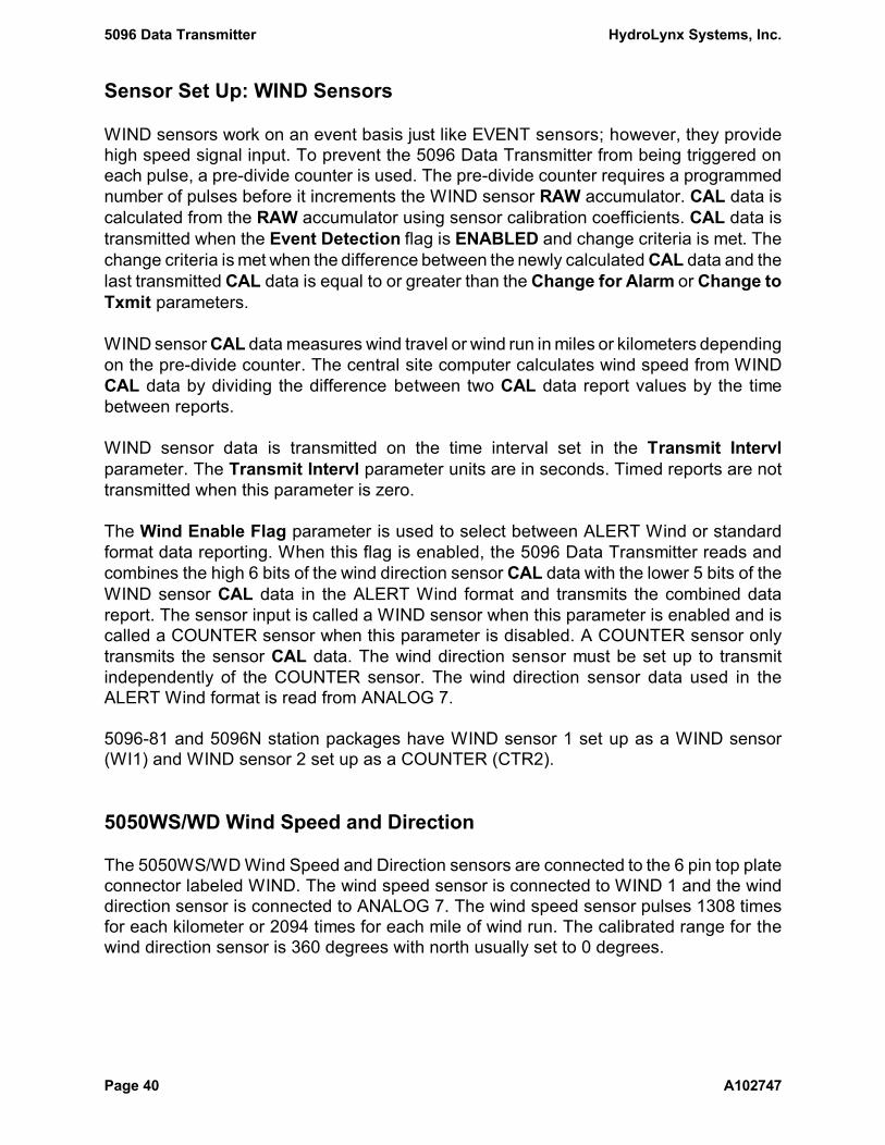
Sensor Set Up: WIND Sensors
WIND sensors work on an event basis just like EVENT sensors; however, they providehigh speed signal input. To prevent the 5096 Data Transmitter from being triggered oneach pulse, a pre-divide counter is used. The pre-divide counter requires a programmednumber of pulses before it increments the WIND sensor RAW accumulator. CAL data iscalculated from the RAW accumulator using sensor calibration coefficients. CAL data istransmitted when the Event Detection flag is ENABLED and change criteria is met. Thechange criteria is met when the difference between the newly calculated CAL data and thelast transmitted CAL data is equal to or greater than the Change for Alarm or Change toTxmit parameters.
WIND sensor CAL data measures wind travel or wind run in miles or kilometers dependingon the pre-divide counter. The central site computer calculates wind speed from WINDCAL data by dividing the difference between two CAL data report values by the timebetween reports.
WIND sensor data is transmitted on the time interval set in the Transmit Intervlparameter. The Transmit Intervl parameter units are in seconds. Timed reports are nottransmitted when this parameter is zero.
The Wind Enable Flag parameter is used to select between ALERT Wind or standardformat data reporting. When this flag is enabled, the 5096 Data Transmitter reads andcombines the high 6 bits of the wind direction sensor CAL data with the lower 5 bits of theWIND sensor CAL data in the ALERT Wind format and transmits the combined datareport. The sensor input is called a WIND sensor when this parameter is enabled and iscalled a COUNTER sensor when this parameter is disabled. A COUNTER sensor onlytransmits the sensor CAL data. The wind direction sensor must be set up to transmitindependently of the COUNTER sensor. The wind direction sensor data used in theALERT Wind format is read from ANALOG 7.
5096-81 and 5096N station packages have WIND sensor 1 set up as a WIND sensor(WI1) and WIND sensor 2 set up as a COUNTER (CTR2).
5050WS/WD Wind Speed and Direction
The 5050WS/WD Wind Speed and Direction sensors are connected to the 6 pin top plateconnector labeled WIND. The wind speed sensor is connected to WIND 1 and the winddirection sensor is connected to ANALOG 7. The wind speed sensor pulses 1308 timesfor each kilometer or 2094 times for each mile of wind run. The calibrated range for thewind direction sensor is 360 degrees with north usually set to 0 degrees.

HydroLynx Systems, Inc. 5096 Data Transmitter
A102747 Page 41
Type the command SET-WI 1 to display the current parameters for WIND 1. The defaultparameters for WIND 1 are:
5096-81 5096N > SET-WI 1[Enter]WIND 1 ID : id idEvent Detection : ENABLED DISABLEDPre-divide Ctr : 3924 3924Transmit Intervl: 0 sec(s) 0 sec(s)Change to Txmit : 1 1Change for Alarm: 10 10Calibration CAL = (RAW * 1)/1 + 0 (RAW * 1)/1 + 0
Type the command SET-AN 7 to display the current parameters for ANALOG 7. Thedefault parameters for ANALOG 7 are:
5096-81 5096N > SET-AN 7[Enter]ANALOG 7 ID : id idEvent Threshold : 0 0Transmit Intervl: 0 sec(s) 0 sec(s)Sample Interval : 0 sec(s) 0 sec(s)Change to Txmit : 1 1Change for Alarm: 50 50Calibration CAL = (RAW * 1)/4 + 0 (RAW * 1)/4 + 0
A Pre-divide Ctr of 3924 for WIND 1 increments the RAW accumulator every 3 kilometers(3 × 1308 = 3924) of wind travel. With the a, b and c parameters set at 1, 1, and 0respectively, the CAL data and RAW accumulator values are equal. Therefore the CALdata transmitted to the central site is wind run in 3 kilometer(km) increments. The centralsite computer converts the data into engineering units (miles or kilometers).
An Event Detection flag ENABLED and a Change to Txmit of 1 transmits a report foreach wind run increment. The WIND sensor set up transmits the wind direction sensorCAL data along with the wind run CAL data in the ALERT Wind format. A Change forAlarm of 10 transmits an alarm report If the CAL data changes by 10 counts during thetransmission hold-off period. A Transmit Intervl of 0 disables timed report transmissions.
WARNING: No Transmit Interval is defined. Do NOT set a transmit interval for WINDsensors!Non-incremental reports will confuse the central site computercomputation of wind speed.
The wind direction ANALOG sensor is read and the CAL data is calculated only when aWIND sensor transmission is made. The Sample Interval and Transmit Intervl of 0disable all other transmissions. The a, b and c parameters of 1, 4, and 0 calculate CALdata for a range of 0 to 255. However, only the upper 6 bits of the CAL data are used inthe ALERT Wind format limiting the range to 0 to 63.

5096 Data Transmitter HydroLynx Systems, Inc.
Page 42 A102747
For standard data collection applications the default settings need not be changed.
Changes to the WIND sensor parameters are made with the SET-WI command. First typethe command SET-WI with a question mark to get the command parameter list:
> SET-WI ?SET-WI sn,{en_ev},{pdc},{t_int},{cgt},{cga},{a},{b},{c},{we},{id}
To change the wind run increment to 1 mile(mi) instead of 3 kilometers(km), change thePre-divide Ctr parameter, pdc, to 2094. Count the commas between sn and the pdcparameter. There are 2 commas. Type the following command to set the parameter andyou will get the response:
> SET-WI 1,,2094[Enter]WIND 1 ID : idEvent Detection : ENABLEDPre-divide Ctr : 2094Transmit Intervl: 0 sec(s)Change to Txmit : 1Change for Alarm: 10Calibration CAL = (RAW * 1)/1 + 0
The R.M. Young Wind Sensor, HydroLynx Systems Model 200-05103, should have its Pre-divide Ctr parameter, pdc, set to 30612 for 3 km or 16327 for 1 mi wind run increments.
WIND sensor reporting can be changed from event to average wind reporting over a timeperiod. Change the Event Detection parameter, en_ev, to 0 to disable prevent eventreporting. Set the Transmit Intervl parameter, t_int, to 3600 to transmit every hourregardless of change (the Change to Txmit and Change for Alarm parameters have noeffect on transmit intervals). Change the Wind Enable Flag parameter, we, to 0 to disableALERT Wind format reporting. WIND sensor CAL data will range from 0 to 2047 and if thePre-divide Ctr parameter, pdc, is set to 2094, each CAL data increment is 1 mile of windrun. Change the central site computer sensor set up to use a raw range to 2048 counts.
Care should be taken is selecting the transmit interval so that the WIND sensor RAWaccumulator does not increment more than 2047 times during the interval. Otherwise thecentral site computer will not be able to calculate the average wind speed correctly.
HydroLynx Systems, Inc. 5096 Data Transmitter
A102747 Page 43
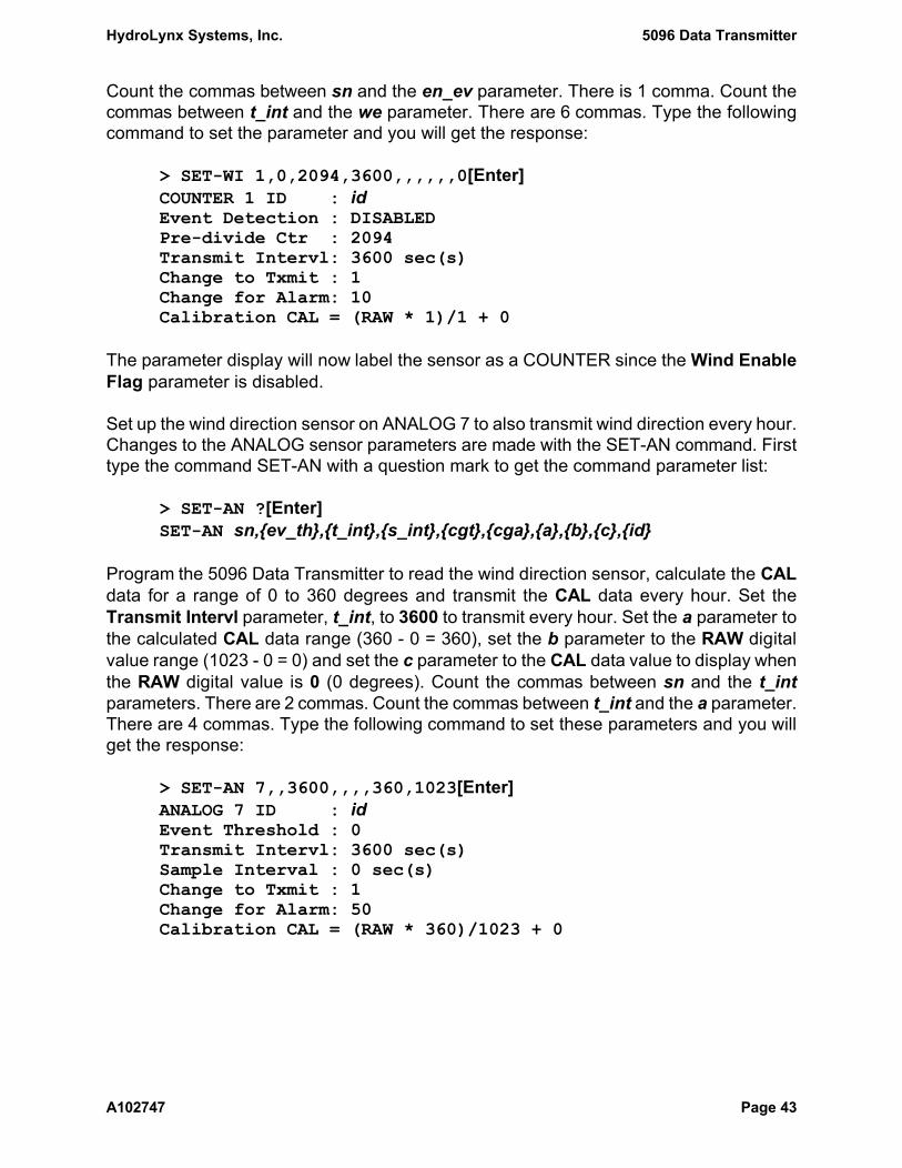
Count the commas between sn and the en_ev parameter. There is 1 comma. Count thecommas between t_int and the we parameter. There are 6 commas. Type the followingcommand to set the parameter and you will get the response:
> SET-WI 1,0,2094,3600,,,,,,0[Enter]COUNTER 1 ID : idEvent Detection : DISABLEDPre-divide Ctr : 2094Transmit Intervl: 3600 sec(s)Change to Txmit : 1Change for Alarm: 10Calibration CAL = (RAW * 1)/1 + 0
The parameter display will now label the sensor as a COUNTER since the Wind EnableFlag parameter is disabled.
Set up the wind direction sensor on ANALOG 7 to also transmit wind direction every hour.Changes to the ANALOG sensor parameters are made with the SET-AN command. Firsttype the command SET-AN with a question mark to get the command parameter list:
> SET-AN ?[Enter]SET-AN sn,{ev_th},{t_int},{s_int},{cgt},{cga},{a},{b},{c},{id}
Program the 5096 Data Transmitter to read the wind direction sensor, calculate the CALdata for a range of 0 to 360 degrees and transmit the CAL data every hour. Set theTransmit Intervl parameter, t_int, to 3600 to transmit every hour. Set the a parameter tothe calculated CAL data range (360 - 0 = 360), set the b parameter to the RAW digitalvalue range (1023 - 0 = 0) and set the c parameter to the CAL data value to display whenthe RAW digital value is 0 (0 degrees). Count the commas between sn and the t_intparameters. There are 2 commas. Count the commas between t_int and the a parameter.There are 4 commas. Type the following command to set these parameters and you willget the response:
> SET-AN 7,,3600,,,,360,1023[Enter]ANALOG 7 ID : idEvent Threshold : 0Transmit Intervl: 3600 sec(s)Sample Interval : 0 sec(s)Change to Txmit : 1Change for Alarm: 50Calibration CAL = (RAW * 360)/1023 + 0

5096 Data Transmitter HydroLynx Systems, Inc.
Page 44 A102747
Sensor Set Up: PEAK WIND Sensors
A PEAK WIND sensor is a virtual input that counts the number of WIND sensor pulsesover the time interval set in the Sample Interval parameter. The maximum count is savedand the corresponding CAL data is calculated using sensor calibration coefficients. PEAKWIND sensor 1 counts pulses from the WIND sensor 1 and PEAK WIND sensor 2 countspulses from WIND sensor 2.
The PEAK WIND CAL data value is transmitted on the time interval set in the TransmitIntervl parameter when the value criteria is met. The value criteria is met when the PEAKWIND CAL data is equal to or greater than the Value for Alarm or Value to Txmitparameters. To disable a PEAK WIND sensor, set both the Transmit Intervl and SampleInterval to 0.
Type the command SET-PK 1 to display the current parameters for PEAK WIND 1. Thedefault parameters for PEAK WIND 1 are:
5096-81, N > SET-PK 1[Enter]PEAK WIND 1 ID : idSample Interval : 0 sec(s)Transmit Intervl: 0 sec(s)Value to Txmit : 0Value for Alarm : 70Calibration CAL = (RAW * 360)/1308 + 0
Changes to the PEAK WIND sensor parameters are made with the SET-PK command.First type the command SET-PK with a question mark to get the command parameter list:
> SET-PK ?SET-PK sn,{s_int},{tx_int},{vgt},{vga},{a},{b},{c},{id}
PEAK WIND sensor RAW value units are in WIND sensor pulses. Set the calibrationcoefficients to calculate the peak wind speed by converting the pulse counts into wind runand adjust for the sample time interval. Set the a parameter to the number of seconds inengineering units divided by the number of seconds in the Sample Interval parameter. Setthe b parameter to the number of pulses per wind run engineering units. The c parameteris not used.
For example, to count the WIND sensor pulses for a 10 second interval and transmit thePEAK WIND every hour, set the Sample Interval parameter, s_int, to 10 and set theTransmit Intervl parameter, tx_int, to 3600. If the engineering units are kilometers perhour (kph), set the a parameter to 360 (3600 seconds per hour ÷ 10 seconds per sampleinterval = 360). Set the b parameter to 1308 (1308 pulses per kilometer of wind run).
HydroLynx Systems, Inc. 5096 Data Transmitter
A102747 Page 45
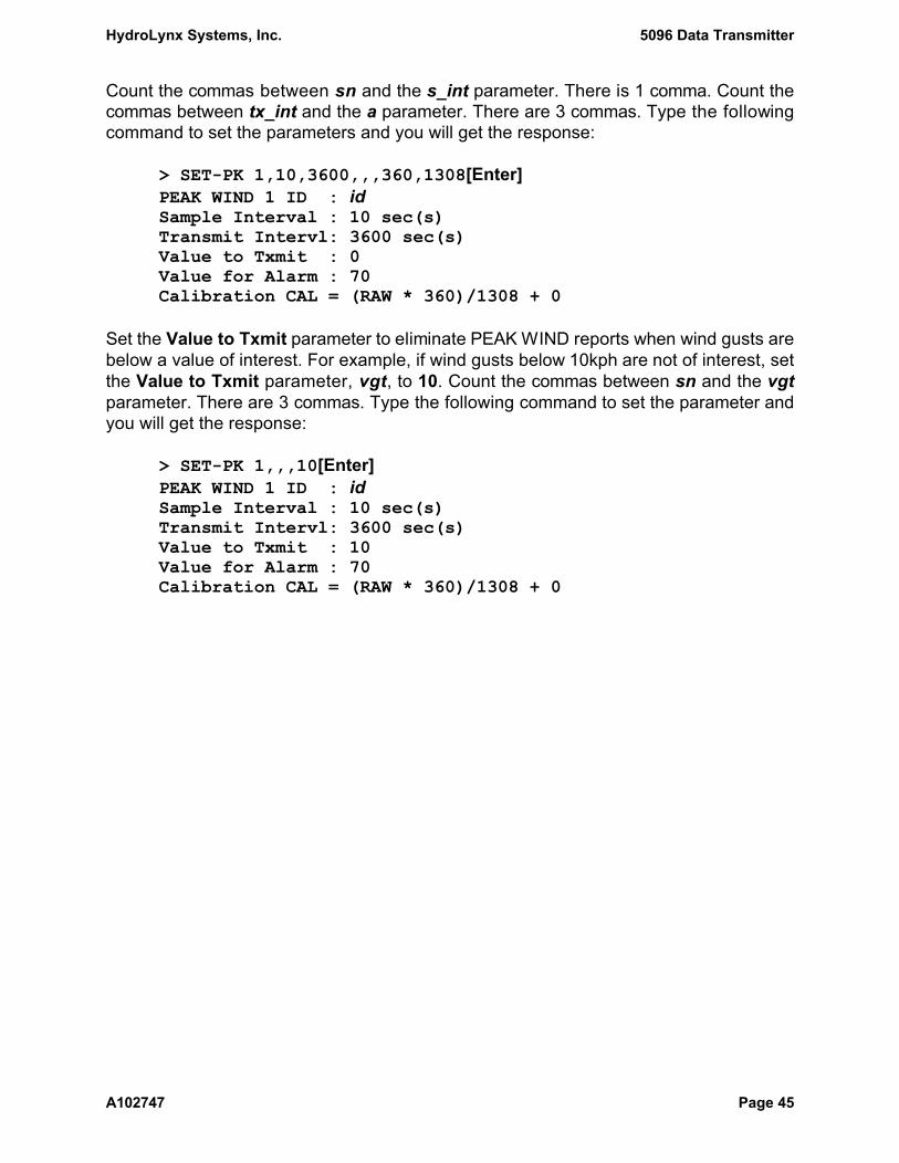
Count the commas between sn and the s_int parameter. There is 1 comma. Count thecommas between tx_int and the a parameter. There are 3 commas. Type the followingcommand to set the parameters and you will get the response:
> SET-PK 1,10,3600,,,360,1308[Enter]PEAK WIND 1 ID : idSample Interval : 10 sec(s)Transmit Intervl: 3600 sec(s)Value to Txmit : 0Value for Alarm : 70Calibration CAL = (RAW * 360)/1308 + 0
Set the Value to Txmit parameter to eliminate PEAK WIND reports when wind gusts arebelow a value of interest. For example, if wind gusts below 10kph are not of interest, setthe Value to Txmit parameter, vgt, to 10. Count the commas between sn and the vgtparameter. There are 3 commas. Type the following command to set the parameter andyou will get the response:
> SET-PK 1,,,10[Enter]PEAK WIND 1 ID : idSample Interval : 10 sec(s)Transmit Intervl: 3600 sec(s)Value to Txmit : 10Value for Alarm : 70Calibration CAL = (RAW * 360)/1308 + 0

5096 Data Transmitter HydroLynx Systems, Inc.
Page 46 A102747
Sensor Set Up: STATUS Sensor
The STATUS sensor can monitor up to 8 digital status inputs. The status line states canbe either open (1) or closed (0). When a status line changes state a data report can betransmitted.
The STATUS sensor must be read at regular time intervals to check for changes in statesince status line state changes do not trigger events. On the time intervals set in theSample Interval and Transmit Intervl parameters the 5096 Data Transmitter reads thestatus line states and saves the RAW binary data. Calibration coefficient parameters arenot available for the STATUS sensor so the CAL data is set to the RAW binary data.
The STATUS sensor CAL data is transmitted on the time interval set in the SampleInterval parameter when the Txmt Zero Status flag criteria and the Alarm Flag orChange Flag criteria are met. The CAL data is transmitted on the time interval set in theTransmit Intervl parameter regardless of any status line state change or flag criteria. Todisable the STATUS sensor set both the Transmit Intervl and Sample Interval to 0.
The Txmt Zero Status flag criteria is met when the parameter is ENABLED or theSTATUS sensor CAL data is not 00000000 or when all status line states return to closed(0) after transmitting a non-zero value.
The Alarm Flag and Change Flag parameters mark which status lines are monitored forchanges in state. The flag parameters can be set to monitor changes in state for ANY orALL marked status lines. The flag criteria is met for ANY when any marked status linechanges state; the flag criteria is met for ALL when all marked status lines change state.The flag criteria is met regardless of any status line state change when either parameteris set to 00000000 (the Txmt Zero Status flag criteria must still be met to transmit).
5096ES Emergency Status Sensor
The Emergency Status Sensor is connected to the 5096 Data Transmitter STATUS sensorto transmit data reports when critical water levels are reached. This sensor is set up as anormally closed switch. When the water rises to the critical level, a float opens the switchand the 5096 transmits a report to the central site. If the sensor is washed away and thecable breaks, an open switch condition also occurs and is detected by the 5096.
The Emergency Status Sensor is connected to the optional 10 pin top plate connectorlabeled STATUS which is connected to the STATUS input. Pins A - H connect to statuslines 1 - 8 and pins I and J are ground.

HydroLynx Systems, Inc. 5096 Data Transmitter
A102747 Page 47
Type the command SET-ST to display the current parameters for the STATUS sensor. Thedefault parameters for STATUS sensor are:
5096-ST, N > SET-ST[Enter]STATUS 1 ID : idTxmt Zero Status: DISABLEDTransmit Intervl: 0 sec(s)Sample Interval : 0 sec(s)Change Flag : ANY 00000000Alarm Flag : ALL 11111111
The default parameters disable the STATUS sensor.
Changes to the STATUS sensor parameters are made with the SET-ST command. Firsttype the command SET-ST with a question mark to get the command parameter list:
> SET-ST ?SET-ST {tx0},{t_int},{s_int},{{-}tf},{{-}af},{id}
Set the Txmt Zero Status parameter, tx0, to 0 to DISABLE or 1 to ENABLE transmissionson sample intervals when all status line states are closed (0).
Set the Change Flag, tf, and Alarm Flag, af, parameters to monitor changes to status linestates. These flag parameters are signed 8 digit binary numbers. Each digit is used tomark whether or not a status line is monitored for changes in state. The rightmost digitmarks status line 1 and the leftmost digit marks status line 8. If the digit is 1 the status lineis monitor; If the digit is 0 the status line is ignored. When a minus sign (-) is enteredbefore the binary number, ALL status lines marked must change in state to cause atransmission. When a plus sign (+) or no sign is entered ANY status line marked canchange in state to cause a transmission.
For example, to programthe 5096 Data Transmitter to transmit STATUS sensor data everyminute when a status line state becomes open (1) set the Sample Interval parameter,s_int, to 60. The Txmt Zero Status parameter set to DISABLED and the Change Flagset to ANY 00000000 will transmit every sample interval as long as the STATUS sensorCAL data is not 00000000. All unused status lines must be grounded so their states areclosed (0). The status line connected to the Emergency Status Sensor will be normallyclosed (0). When the sensor switch opens the status line state becomes open (1) andtransmissions begin. When the sensor switch becomes closed (0), one last transmissionis made. Count the commas between tx0 and the s_int parameter. There are 2 commas.

5096 Data Transmitter HydroLynx Systems, Inc.
Page 48 A102747
Type the following command to set the parameters and you will get the response (be sureto include the space after the command):
> SET-ST ,,60[Enter]STATUS 1 ID : idTxmt Zero Status: DISABLEDTransmit Intervl: 0 sec(s)Sample Interval : 60 sec(s)Change Flag : ANY 00000000Alarm Flag : ALL 11111111
To program the 5096 Data Transmitter to read the STATUS sensor every minute andcheck for state changes on status lines 1 and 2 but ignore all other unused status lines,set the Change Flag parameter, tf, to 00000011 marking status line 1 and 2. To transmitan alarm if both status lines 1 and 2 change, set the Alarm Flag parameter, af, to-00000011. Set the Txmt Zero Status parameter, tx0, to 1 to ENABLE transmission onthe sample interval even if all status line states are closed (0). Set the Transmit Intervlparameter, t_int, to 86400 to transmit every day regardless of status line state changes.Type the following command to set the parameters and you will get the response:
> SET-ST 1,86400,,00000011,-00000011[Enter]STATUS 1 ID : idTxmt Zero Status: ENABLEDTransmit Intervl: 86400 sec(s)Sample Interval : 60 sec(s)Change Flag : ANY 00000011Alarm Flag : ALL 00000011

HydroLynx Systems, Inc. 5096 Data Transmitter
A102747 Page 49
Sensor Set Up: SERIAL Sensor
A SERIAL sensor can store data in one of the 8 analog input channels. Type the commandSET-SERIAL sn with parameters to replace the storage of analog channel sn with a serialsensor. The analog input will no longer be read for this channel. Instead data will be storedwhen the WRITE-SERIAL command is received on the console port. The WRITE-SERIALcommands saves a RAW data value and computes the CAL data value using the sensorcalibration coefficients.
The console baud rate must match the baud rate of the equipment that will issue theWRITE-SERIAL command. The default baud rate of the EPROM type S is 9600 baud. Seethe command SET-BAUD in Section 4.7 to change the console baud rate.
Changes to the SERIAL sensor parameters are made with the SET-SERIAL command.First type the command SET-SERIAL with a question mark to get the command parameterlist:
> SET-SERIAL ?[Enter]SET-SERIAL sn,{ev_th},{t_int},{s_int},{cgt},{cga},{a},{b},{c},{id}
To program the 5096 Data Transmitter to check for a change of 5 in the serial input 5 CALdata every 15 minutes, set the Change to Txmit, cgt, parameter to 5 and the SampleInterval, s_int, parameter to 900. To transmit the sensor data value every day regardlessof any CAL data change, set the Transmit Intervl, t_int, parameter to 86400 (24 hours).To transmit alarms on a change of 50 set the Change for Alarm, cga, parameter to 50.Set the calibration coefficients a, b and c parameters to 1, 1 and 0 to set the CAL datavalue to the same value as the RAW data value. Count the commas between sn and thet_int parameter. There are 2 commas. Type the following command to set theseparameters and you will get the response:
> SET-SERIAL 5,,86400,900,5,50,1,1,0[Enter]SERIAL 5 ID : idEvent Threshold : 0Transmit Intervl: 86400 sec(s)Sample Interval : 900 sec(s)Change to Txmit : 5Change for Alarm: 50Calibration CAL = (RAW * 1)/1 + 0

5096 Data Transmitter HydroLynx Systems, Inc.
Page 50 A102747
2.2 Hardware Installation
After unpacking the 5096 Data Transmitter check that it has not been damaged inshipment. Set it up on a work bench and identify the different components. This gives youthe opportunity to familiarize yourself with the 5096 and to check that it is functioningproperly. Changes to any of the default parameter settings can also be done at this time.A terminal or computer with terminal emulation software is used as the console to programand test the 5096.
Check that a central site computer or 5062 Remote Station Tester is set up to receive andverify radio transmitter signals from the 5096 Data Transmitter.
The hardware installation may vary depending on the type of transmitter enclosure.Differences in installation are noted by the transmitter enclosure type. For example:
5096 The 5096 Data Transmitter is enclosed in an 8 inch diameter aluminumcanister.
5096N The 5096N Data Transmitter is enclosed in a NEMA 4X fiberglass enclosure.
2.2.1 Console Cable Connection
Connect the console to the 5096 using the 5071C-5096 cable as described in Section2.1.1. The cable connects to the board at J5, the 9 pin female 'D' connector on the upperright side.
2.2.2 5050LLFT and 5050TS Modifications
If a 5050LLFT or a 5050TS is to be connected to the 5096 the following modification mustbe made. This modification will not affect the operation of these devices on either a 5050or a 5096. If you need assistance contact the Customer Service Department.
Open the female MS connector and cut the wire at pin B. Reassemble the connector.
WARNING: Failure to implement this modification will cause DAMAGE to the 5096.

HydroLynx Systems, Inc. 5096 Data Transmitter
A102747 Page 51
2.2.3 Radio Transmitter Check
Radio transmitter Frequency error, Deviation and Power output are factory tested andrecorded on the Test Result Report (see Section 6.2, Document Number A101018-4)provided with each 5096 Data Transmitter. The FCC requires that these tests beperformed at time of installation and every year thereafter. Should any adjustments benecessary, they should be performed by a qualified technician using the proper testequipment.
For optional dual frequency radios check that the switch on the 5096 Data Transmitterchassis is set to the proper frequency.
2.2.4 Antenna Connection
5096 The antenna is connected to the female BNC connector on the top plate.
5096N The antenna is connected to the female N-type connector on the enclosure.
2.2.5 Battery Connection
5096 To connect the battery place the battery bracket over the battery with the redand black tapes aligned. Connect the red wire to the positive terminal thenconnect the black wire to the negative terminal.
Carefully lower the battery on end into the canister. Check that there is asilica gel absorbent pack (Desiccant bag) in the canister. Place the 5096Data Transmitter into the canister and rotate to align the two holes over thelatch screws and put the knobs on.
5096N Turn off the POWER switch on the Screw Terminal Panel. Install the batterywith the terminals on the top left and screw the battery bracket into place.Connect the red wire to the positive terminal, marked with red tape andconnect the black wire to the negative terminal marked with black tape.
WARNING: Failure to correctly connect the battery can cause extensive DAMAGEto the 5096 Data Transmitter.
2.2.6 Solar Panel or AC Charger Connection
5096 Connect the solar panel or AC charger to the 3 pin MS male connectorlabeled 12 VDC IN.

5096 Data Transmitter HydroLynx Systems, Inc.
Page 52 A102747
5096N Connect the solar panel or AC charger to the 3 pin MS male connector. Turnon the POWER switch on the Screw Terminal Panel.
WARNING: Connect the battery before connecting the solar panel or AC charger.Never operate the 5096 Data Transmitter without a battery connected.
2.2.7 Sensor Connectors
5096 Sensors are connected to the MS bulkhead connectors on the top plate. Thenumber of pins and rotation of each connector is unique for each sensorinput which prevents incorrect installation. See Section 6.2 DrawingAC104180.
5096N Sensors are connected to the Screw Terminal Panel. Sensor cables enterthe enclosure through the cable strain reliefs. A wiring diagram for typicalsensors to the 5096N is provided in Section 6.2 Drawing AC107911.
Warning: Label sensor cables to prevent damage to the sensors or the 9601board due to incorrect wiring on the Screw Terminal Panel.
2.2.8 Data Transmitter Installation
5096 The design of the 5096 Data Transmitter allows it to be installed in astandpipe by lowering it from the top of the standpipe or through an optionaldoor. When lowering from the top of the standpipe, attach a 'lifting rope' tothe top plate handle and tie off the other end of the rope to the bracket nearthe top of the standpipe. The cables for the antenna, solar panel and sensorinputs are connected before lowering the transmitter into the standpipe.Carefully lower the transmitter to the bottom of the standpipe.
5096N The 5096N in the NEMA type 4X enclosure is designed to be mounted eitheron a pole or on a backboard. If the unit is exposed to direct sunlight, a sunshield should be used to protect the unit from excessive heat. After theenclosure is mounted, cut excessively long cables (cable that needs to becoiled is excessive) before connecting the antenna, solar panel and sensorinputs to the transmitter. Check that there is a silica gel absorbent pack(desiccant bag) in the enclosure.
HydroLynx Systems, Inc. 5096 Data Transmitter
A102747 Page 53
3 Hardware Inputs and Outputs
3.1 Hardware Introduction 54
3.2 Sensor Inputs 553.2.1 Digital Inputs 553.2.2 Analog Inputs 563.2.3 Virtual Inputs 573.2.4 Serial Sensor Interface 57
3.3 Board Features 583.3.1 Switches 583.3.2 LEDS 603.3.3 Test Points 613.3.4 Internal Battery Jumper 62
3.4 Communication Outputs 633.4.1 Telemetry Interface 633.4.2 Console Interface 63

5096 Data Transmitter HydroLynx Systems, Inc.
Page 54 A102747
3.1 Hardware Introduction
The 5096 Data Transmitter has the following inputs, outputs and board features:
Sensor Inputs
! Digital inputs2 EVENT inputs2 COUNTER/WIND inputs1 8-bit STATUS input
! Analog inputs7 external ANALOG inputs1 internal BATTERY voltage input
! Virtual inputs2 virtual PEAK WIND inputs computed from WIND input values
! Serial Sensor Interface1 Absolute encoder input connected to the serial sensor interface or8 serial sensors written to with the WRITE-SERIAL command.
Board Features
! SwitchesRESET, TEST and Station ID number
! LEDs for monitoring board activity and test resultsRUN, TEST ERR, SENS PWR, PWR ERR, TX ON and TEST
! Test points for board level testing and troubleshootingTP1(TxData), TP2(Battery), +5V SENS(VREF), CLOCK, GND, +5V(Vcc)
! On board battery with disconnect jumper to reset battery-backed parameters
Communication Outputs
! Radio telemetry interface for data reporting
! Console interface for programming and monitoring the 5096 Data Transmitter
HydroLynx Systems, Inc. 5096 Data Transmitter
A102747 Page 55
3.2 Sensor Inputs
The 5096 Data Transmitter design supports connections to a variety of digital and analoginputs. Some of the standard sensor configurations used with the 5096 Data Transmitterare covered in Section 2.1.6. See Drawings AC104180 and AC107911 in Section 6.2.
3.2.1 Digital Inputs
The 5096 Data Transmitter supports three types of digital inputs: EVENT,COUNTER/WIND, and STATUS. Each digital input type has a unique characteristic suitedto a particular application as defined below.
EVENT inputs: (2 provided)
! Each digital input has two input trigger lines and a status line that can increment ordecrement the input's accumulator value, depending on the mode selected byprogramming. When the count is incremented beyond the accumulator's maximumvalue, the accumulator is reset to zero. When the count is decremented below zero,the accumulator is set to its maximum value, 65535.
! The input is capable of continuous counting rates of 60Hz and burst counting ratesof as high as 100Hz for several seconds.
! Transmissions can be initiated when an event occurs or on a programmable timeinterval or both.
COUNTER / WIND inputs: (2 provided)
! Each input has a single trigger line that will increment the input's accumulator valuewhen its counter reaches the programmed pre-divide value. For example, if the pre-divide value is 12, the accumulator will increment by one, each time that 12 signalsare counted on the trigger line. When the count is incremented beyond theaccumulator's maximum value, the accumulator is reset to zero.
! The pre-divide counter allows continuous input frequencies of up to 600 KHz andburst rates of up to 3 MHz for several seconds.
! Transmissions can be initiated when an event occurs or on a programmable timeinterval or both.
! The standard configuration for WIND 1 is set up for the Model 5050WS wind speedsensor's signal (AC sine wave). However, it can be reprogrammed as a generalpurpose up-counter COUNTER 1.

5096 Data Transmitter HydroLynx Systems, Inc.
Page 56 A102747
! The standard configuration for COUNTER 2 is set up as a general purpose up-counter. COUNTER 2 accepts momentary contact closures as its signals. Thiscounter can also be programmed as WIND 2
STATUS inputs: (8 provided)
! Each bit in the 8-bit status value represents the status of a single contact closureinput line.
! All 8 inputs are processed and transmitted together as a single STATUS sensorvalue.
! The STATUS inputs generate transmissions on a timed interval. A sample intervalis defined to check for changes in the status line states. Transmissions can be sentfor any or all status line changes. A transmit interval is defined to transmit theSTATUS value regularly regardless of any status line state changes.
3.2.2 Analog Inputs
ANALOG inputs: (7 provided)
! Each ANALOG input has an input range of 0 to 5 volts.
! The 5096 Data Transmitter has a 10 bit A/D converter, which provides an accuracyof ± 0.2% (± 10 millivolts).
! Transmissions can be initiated on a specified change in the input voltage level(defined as an event) or on a programmable time interval or both.
BATTERY Sensor input: (1 provided)
! The BATTERY sensor input is part of the 5096 Data Transmitter's internal design,no external connector is required.
! The BATTERY sensor input reports the battery voltage within ± .02 volt.
! Transmissions can be initiated on a specified change in battery voltage or on aprogrammable time interval or both.

HydroLynx Systems, Inc. 5096 Data Transmitter
A102747 Page 57
3.2.3 Virtual Inputs
PEAK WIND inputs: (2 provided)
! On every sample interval, the wind sensor input count is compared to the currentcount for the PEAK WIND sensor and the maximum count is saved. The count fromWIND 1 is used for PEAK WIND 1 and the count from WIND 2 is used for PEAKWIND 2.
! Transmissions of the maximum value are sent on a programmable time interval.
3.2.4 Serial Sensor Interface
Absolute encoder input: (1 provided)
! The EVENT 1 input can be switched from a digital input to an absolute encodersensor connected to the serial sensor interface. This is done by selecting eventmode 12 using the SET-EV command (See Section 4.7 and 4.8).
! The absolute encoder is not an event sensor. It is read on a programmed sampleinterval.
! Transmission are made on a specified change for the sample interval or regardlessof change for a programmable transmit interval.
Serial data input: (8 provided)
! Serial data can be written to the 5096 Data Transmitter using the WRITE-SERIALcommand.

5096 Data Transmitter HydroLynx Systems, Inc.
Page 58 A102747
3.3 Board Features
The 9601 board features switches for transmitter RESET, TEST and Station ID select,LEDs for monitoring board activity and testing, test points for board level testing andtroubleshooting, and an internal battery jumper to allow battery-backed parameters to bereset to default values and erase data logging memory.
3.3.1 Switches
No. Name Type Function 1 RESET Momentary Push Button Performs a system reset. The
system reset is functionallyequivalent to a power-up reset.
2 TEST Momentary Push Button Starts a test transmission followedby a series of internal functionalitytests.
3-6 ID Select 10 Pos. Rotary Switch Set the Station ID number. DefaultSensor ID numbers are offset fromthe Station ID number.
To locate the switches, refer to the M9601 PCB assembly diagram in Section 6.2.
RESET Switch (SW1)
RESET is a push button switch located on the right hand edge of the 9601 board and ismarked RESET.
When the RESET switch is pressed and released, the 5096 Data Transmitter restarts itsprogram, and displays on the console:
HydroLynx Systems, Inc. - 5096 ALERT Data TransmitterCopyright Year. All Rights Reserved.P9601-01-pn Ver verR Month Day, YearStation ID : staid
where pn is the firmware part number suffix, ver is the firmware version number, R is theradio type, Month Day, Year is the month, day, and year of version release date and staidis the Station ID read from the ID switches.
If the TEST switch is held down and the RESET switch is pressed when the RESETINITfeature is enabled, the 5096 Data Transmitter will execute the command to reset allbattery-backed-up parameters to default values and clear logging memory. The 5096 will

HydroLynx Systems, Inc. 5096 Data Transmitter
A102747 Page 59
display on the console:
Parameters resetLogging memory cleared
When the 5096 Data Transmitter program starts, it compares the contents of a RAMmemory location with a number stored in the EPROM program. If the two numbers do notmatch, the 5096 assumes the EPROM program has been changed or that RAM corruptionhas occurred. In either case, the 5096 executes an INIT command to reset all battery-backed parameters to their default values and displays on the console:
Battery backed up memory lost: resetting all parametersLogging memory cleared
TEST Switch (SW2)
TEST is a push button switch located at the bottom left corner of the 9601 board and ismarked TEST.
When the TEST switch is pressed, the current data values of all active sensors aretransmitted and a Level 1 test is executed. See Section 5.2.2 and 5.2.3 for the actionsperformed by the TEST switch.
Pressing the TEST switch usually has no effect on either the battery-backed parametersor the data logging memory. The one exception is when the 5096 Data Transmitter is resetwhile the TEST switch is pressed and held down. In this case the 5096 Data Transmitterwill execute the INIT command to reset all battery-backed-up parameters to default valuesand clear logging memory.
ID Switches
The 9601 board has a set of four rotary switches, each with ten numbered positions. Theseswitches are used to set the Station ID number. The default Sensor ID numbers are offsetfrom the Station ID number.
When a 5096 Data Transmitter transmits sensor data values, it also sends the sensor IDnumber. This Sensor ID number is used by the base station computer software for datastorage in its database.
The ID switches (SW3 through SW6 on the schematic drawing) are located on the lefthand edge of the board and are labeled ID0, ID1, ID2, ID3.
The number set by ID3 is the thousands digit. ID2 is the hundreds digit. ID1 is the tensdigit, and ID 0 is the ones digit. For example, a Station ID of 1930 would be set by placingthe switches into the following positions:

5096 Data Transmitter HydroLynx Systems, Inc.
Page 60 A102747
ID3 = 1ID2 = 9ID1 = 3ID0 = 0
Default Sensor ID offsets and example ID numbers for Station ID#, 1930 are:
Sensor Sensor type Class ID offset ExamplePK1 Peak wind D ID# - 6 1924PK2 Peak wind D ID# - 5 1925ST Status D ID# - 4 1926WI1 (CTR1) Wind Speed D ID# - 3 1927CTR2 (WI2) _____________ D ID# - 2 1928EV1 Float D ID# - 1 1929EV2 Precipitation D ID# 1930AN1 Rel. Humidity A ID# + 1 1931AN2 Temperature A ID# + 2 1932AN3 Pres. Transducer A ID# + 3 1933AN4 Barometric Pres. A ID# + 4 1934AN5 _____________ A ID# + 5 1935AN6 _____________ A ID# + 6 1936AN7 Wind Direction A ID# + 7 1937BATT Battery Voltage A ID# + 8 1938
3.3.2 LEDS
6 LEDs are provided on the 9601 board to aid in monitoring Data Transmitter activity andto help in testing and troubleshooting.
To conserve power, the LEDs are normally all off. When a 5071C-5096 cable is connectedto the console port the RUN LED stays on.

HydroLynx Systems, Inc. 5096 Data Transmitter
A102747 Page 61
The LED numbers, their color, names and functions are:
No. Color Name Function 1 Green RUN On while microprocessor is active or the console
is plugged in. Flashes each clock tick(default=10 sec.) when in power saving mode.
2 Red ERR Flashes 4 times when a Level 1 Test detectserrors.
3 Yellow SENS PWR On when switched ANALOG power is on.
4 Red PWR ERR On for errors in the 5 volt Reference powersupply (VREF).
5 Red Tx ON On when the radio is powered.
6 Yellow TEST On during a test sequence.
3.3.3 Test Points
Test points are provided on the 9601 board to aid in testing and troubleshooting DataTransmitter performance.
The test point numbers, names, labels and descriptions are:
No. Name Label Description 1 Tx Data TP1 RF transmit data stream (audio to the radio);
requires a frequency counter or an oscilloscope.
2 Battery TP2 Battery voltage should be 12.5 - 14.0 Vdc
3 VREF +5V SENS Switched reference voltage should read 5.000 ±0.005 Vdc when an analog sensor is being reador the analog power has been turned on.
4 Clock CLOCK Internal system clock; requires a frequencycounter or an oscilloscope.
5 Ground GND Ground reference point.
6 Vcc +5V +5 Vdc power for the logic circuits; should read5.00 ± 0.25 Vdc at all times.

5096 Data Transmitter HydroLynx Systems, Inc.
Page 62 A102747
3.3.4 Internal Battery Jumper
A shorting-block connector for disconnecting the internal back-up battery is located at JB2on the right side of the board. To reset all battery-backed parameters to their defaultvalues and clear data logging memory, disconnect the external main battery and removethe internal battery jumper at JB2.
WARNING: Removing the internal battery jumper and disconnecting theexternal battery will reset all battery-backed parameters todefault values and erase all data stored in logging memory.
Disconnect the internal battery jumper, JB2, and the main battery, then wait approximately60 seconds. Reconnect the battery jumper and connect the main battery. When the 5096Data Transmitter program starts it compares a RAM memory value to a value stored in theEPROM program. If the two values do not match, the program will execute the INITcommand. On the console, the 5096 will display its power up message followed by:
Battery backed up memory lost: resetting all parametersLogging memory cleared

HydroLynx Systems, Inc. 5096 Data Transmitter
A102747 Page 63
3.4 Communications
The 5096 Data Transmitter provides a radio telemetry interface that allows it to reportsensor data values to the base station software system. It also provides a consoleinterface that allows a console terminal to program and monitor Data Transmitter activity.
3.4.1 Telemetry Interface
The 5096 telemetry interface allows the 5096 Data Transmitter to be connected to a varietyof radio transmitters for the transmission of sensor data. The data is transmitted using theselected ALERT format and standard ALERT tones.
The supported ALERT formats are ASCII, Binary, ALERT wind, Enhanced ALERT andEnhanced IFLOWS (both with CRC). The transmission formats are described in drawingAC107484 in Section 6.2.
The standard ALERT transmission tones are 2140Hz (one) and 1920HZ (zero).
Radio transmitter frequencies vary depending on system needs.
The telemetry interface connection is J4 on the 9601 board. The pin-out is:
Pin Name Description 1 TX Audio out2 PTT Key transmission3 TX-PWR Transmitter power4 RX-PWR Receiver power (Not used)5 RX Audio in (Not used)6 GND Ground
3.4.2 Console Interface
The console interface is used to connect the 5096 Data Transmitter to a console forprogramming and monitoring purposes.
The console interface is an RS232 serial port configured as a DTE. The RS232 serial portis a 9 pin female 'D' connector located on the upper right corner of the 9601 board at J5.
The fact that this interface port is configured as a DTE means that you must use a NULLModem cable to communicate with the 5096 Data Transmitter from a computer serial port.
An additional feature of the 5096 Data Transmitter is that it enters a power-down mode 20seconds after the last command entered. After the 5096 enters power-down mode, it takesone keystroke to wake it up. Unfortunately, the keystroke is lost.

5096 Data Transmitter HydroLynx Systems, Inc.
Page 64 A102747
To prevent the 5096 Data Transmitter from entering power-down mode, connect DTR andDSR pins (4 and 6) on the console serial port. As long as these pins are connected, the5096 will stay in RUN mode and never enter power-down mode.
Version 4.0 firmware switches the serial port from the console to the serial sensor interfaceby dropping the CTS signal. To prevent console commands from interfering with serialsensor interrogations, set up the console terminal software to use hardware flow control(RTS/CTS).
The pin-out for the serial port is:
Pin Name Description 1 CD Carrier Detect (Not used)2 RXD Receive Data, serial in3 TXD Transmit Data, serial out4 DTR Data Terminal Ready5 GND Signal Ground6 DSR Data Set Ready7 RTS Request to Send (Not used)8 CTS Clear to Send9 RI Ring Indicator (Not used)

HydroLynx Systems, Inc. 5096 Data Transmitter
A102747 Page 65
4 Programming
4.1 Introduction 67
4.2 Firmware Version 67
4.3 Rules for Entering Commands 68
4.4 Battery Protected Parameters 69
4.5 Command Help Facilities 69
4.6 Command Examples 70
4.7 Command Descriptions 71AD-OFF 72AD-ON 73ALIGN 74CHK-MEM 75CLEAR-MEM 76GET-MEM 77HELP 80INIT 81READ-AN 82READ-BATT 83READ-CTR 84READ-EV 85READ-IDSW 86READ-PK 87READ-SERIAL 88READ-ST 89READ-WI 90RESET 91RESETCNT 92RESETINIT 93SET-AN 94
5096 Data Transmitter HydroLynx Systems, Inc.
Page 66 A102747
SET-BATT 95SET-BAUD 96SET-CTR 97SET-CTRRESET 98SET-ENH 99SET-EV 100SET-EVRESET 101SET-HOLDOFF 102SET-MEM 103SET-PK 104SET-RFWARM 105SET-SERIAL 108SET-SPT 109SET-ST 110SET-WARM 111SET-WI 112SHOWALL 113TEST 114TEST-TX 115TIME-MODE 116TIME= 117WRITE-CTR 118WRITE-EV 119WRITE-SERIAL 120
4.8 Parameter Descriptions 121
4.9 Error Messages 135
HydroLynx Systems, Inc. 5096 Data Transmitter
A102747 Page 67
4.1 Introduction
This section describes the commands used to program the 5096 Data Transmitter. An IBMcompatible personal computer is typically used as the operator's programming console.The personal computer may be a notebook or portable style for use at the remote station.The personal computer is connected into the 5096 through the RS232 port with a5071C-5096 cable. The software used to program and operate the 5096 can be HydroLynxSystems 5073PT Palmtop 5096 Programming Software, Microsoft Windows Terminalsoftware, Microsoft HyperTerminal software, or any other terminal emulation software.
4.2 Firmware Version
9601-01 version 4.4 is the current version of HydroLynx Systems firmware release for the5096 Data Transmitter. Descriptions of both the system commands and the defaultparameters for version 4.4 are provided within this manual. The version section in thecommand description shows versions which added the command or made changes tocommand parameters or defaults.
HydroLynx Systems invites customer comments and suggestions for future firmwareimprovements and features. Whenever new firmware versions are released, updates tothis manual will also be released. Version 4.4 commands and default parameters willremain in effect unless specifically changed by an addendum to the manual. Always checkfor the latest firmware version and related documentation whenever the 5096 DataTransmitter is to be programmed.
See Section 6.3 for a list of 5096 Firmware Enhancements.

5096 Data Transmitter HydroLynx Systems, Inc.
Page 68 A102747
4.3 Rules for Entering Commands
Most of the 5096 Data Transmitter commands have one or more associated parameters.Some of the commands require specific parameters, while other commands may haveparameters that are optional. The rules for entering commands and parameters are:
! Commands may be typed in either upper or lower case after the 5096 DataTransmitter command prompt, >. Commands are executed when [Enter] is pressed.
! When a command has parameters associated with it, the first parameter must beseparated from the command by one or more spaces.
! When two or more parameters are specified, the parameters must be separated bya field delimiter. A field delimiters can be a space, comma (,), colon (:), or forwardslash (/).
! Parameters shown enclosed in braces {} are optional and may be omitted. Anomitted parameter retains the same value it had before the command was executed(unless otherwise specified).
! If one or more parameters are omitted between two that are specified, non-spacefield delimiters must still be typed to mark the omitted parameters.
! If all parameters are omitted after a given point, then the field delimiter for thoseparameters need not be typed.
! All parameters must be typed in the range and format specified in the commanddescription.
! A period (.) will repeat the last command.
! ^C ([Ctrl]C) will break out of the last command.
! ^S ([Ctrl]S) will pause the display during command execution.
NOTE: To simplify the command descriptions that follow, the field delimiter isshown as a comma. A space, colon, or forward slash can besubstituted for the comma.

HydroLynx Systems, Inc. 5096 Data Transmitter
A102747 Page 69
4.4 Battery Protected Parameters
The main battery powers the 9601 board, radio, and ANALOG sensors. Additionally, the5096 Data Transmitter has an independent, small, long-life battery that maintains thevalues stored in the system's memory. These values are referred to as "battery-backed-up"or battery protected parameters. Battery protected values are maintained in the 5096memory independent of whether or not the main battery is connected or the condition ofthe battery's state of charge.
The parameters may be changed by command. The new values are retained until bothbatteries are disconnected or until the INIT command is given.
4.5 Command Help Facilities
The 5096 Data Transmitter can help the operator to enter commands correctly. Eachcommand has zero or more parameters which can be listed on the console either by typingthe command followed by a space and a question mark (?) or by typing the word HELPfollowed by a space and the command. For example type either of these commands andyou will get the response:
> SET-AN ?[Enter] or > HELP SET-AN[Enter]SET-AN sn,{ev_th},{t_int},{s_int},{cgt},{cga},{a},{b},{c},{id}
HELP, entered by itself, lists all commands, and HELP followed by a partial command willlist all commands that are similar or close to that entry.
If a command cannot be interpreted, an error message will be displayed. Refer to Section4.9 for a complete list of error messages.

5096 Data Transmitter HydroLynx Systems, Inc.
Page 70 A102747
4.6 Command Examples
The following examples show how the SET-AN command can be used to set and view theparameters associated with it. The rules demonstrated in this example apply to allcommands. To set the following parameters:
sn ev_th t_int s_int cgt cga a b c id
1 0 3600 50 5 20 1 5 10 1931
type the following command after the > prompt:
> SET-AN 1,0,3600,50,5,20,1,5,10,1931[Enter]or
> SET-AN 1 0 3600 50 5 20 1 5 10 1931[Enter]
If a parameter is not going to be changed, it may be omitted by using consecutivenon-space delimiters: comma, slash, colon ( , / : ). For example, to change only ev_th, cgt,a, and b (but NOT change t_int, s_int, cga, c, and id):
sn ev_th t_int s_int cgt cga a b c id
1 2 ---- -- 6 -- 2 11 -- ----
type the following command after the > prompt:
> SET-AN 1,2,,,6,,2,11[Enter]
Note that spaces will NOT serve to delimit an omitted parameter.
To display the current parameters values for ANALOG 1 type the command after the >prompt and you will get the response:
> SET-AN 1[Enter]ANALOG sn ID : idEvent Threshold : ev_thTransmit Intervl: t_int sec(s)Sample Interval : s_int sec(s)Change to Txmit : cgtChange for Alarm: cgaCalibration CAL=: (RAW * a)/b + c

HydroLynx Systems, Inc. 5096 Data Transmitter
A102747 Page 71
4.7 Command Descriptions
A description of all 5096 Data Transmitter commands follows, in alphabetical order. Theformats for input and output, as well as the command's parameters are shown. Bracesindicate {optional} parameters.
The HEADING section shows the command's name and function.
The FORMAT section shows the command name in CAPITAL letters followed by theparameter list in italics. Optional parameters are enclosed in braces, {s_int}. Optionalparameters that are not included in a command line are replaced by default values.Choices in optional parameters are separated by a bar, {choice1 | choice 2}.
The OUTPUT section shows the console display after the command has beenentered. Parameter names that are replaced by values are displayed in italics. The outputparameter names are described in tables with ranges and default values.
The PARAMETER section shows each parameter's name, description, range, and defaultvalues for 5096N version 4.4 (See Section 2.1.6 for other package default parameters).All command parameters are described in section 4.8.
The DESCRIPTION section describes the actions performed by the command and includesexamples. In the examples, commands are typed after the command prompt > and arefollowed on the next line by the command output. For example:
> AD-ON[Enter]Analog Power ON
Warnings associated with a command are highlighted with bars. For example:
WARNING: This command will reset all parameters to their default values.
The SEE section lists the names of related commands.

5096 Data Transmitter HydroLynx Systems, Inc.
Page 72 A102747
AD-OFF Turn off the switched analog power.
FORMAT: AD-OFF
OUTPUT: Analog Power OFFor
Analog Power Remaining On
PARAMETERS: None
DESCRIPTION: The AD-OFF command is used to turn off the switched analog powerafter it has been turned on by the AD-ON command. The AD-ON andAD-OFF commands must be entered in pairs. For example thesequence:
> AD-ON[Enter]Analog Power ON> AD-OFF[Enter]Analog Power OFF
turns the analog power on and then off. The sequence:
> AD-ON[Enter]Analog Power ON> AD-ON[Enter]Analog Power Already On> AD-OFF[Enter]Analog Power Remaining On
would leave the analog power on. The single AD-OFF commandcanceled only one of the two AD-ON commands.
VERSION: 1.4 Original command set.
SEE: AD-ON, READ-AN, READ-BATT
HydroLynx Systems, Inc. 5096 Data Transmitter
A102747 Page 73
AD-ON Turn on the switched analog power.
FORMAT: AD-ON
OUTPUT: Analog Power ONor
Analog Power Already On
PARAMETERS: None
DESCRIPTION: The AD-ON command is used to turn on the switched analog power.It can be turned on to allow the testing of the analog circuitry and thesensor connected to it. The AD-ON and AD-OFF commands must beentered in pairs. For example the sequence:
> AD-ON[Enter]Analog Power ON> AD-OFF[Enter]Analog Power OFF
turns the analog power on and then off. The sequence:
> AD-ON[Enter]Analog Power ON> AD-ON[Enter]Analog Power Already On> AD-OFF[Enter]Analog Power Remaining On
would leave the analog power on. The single AD-OFF commandcanceled only one of the two AD-ON commands.
VERSION: 1.4 Original command set.
SEE: AD-OFF, READ-AN, READ-BATT

5096 Data Transmitter HydroLynx Systems, Inc.
Page 74 A102747
ALIGN Align all system timers to the same starting point.
FORMAT: ALIGN
OUTPUT: All timers aligned
PARAMETERS: None
DESCRIPTION: After timing intervals have been entered using the sensor SETcommands, it may be desirable to align all of the timers so that theystart at the same time. This can be done in any of two ways:
1 - The ALIGN command can be entered from the console.
2 - The SET-SPT command can be entered from the console tochange the clock-tick which re-aligns the timing intervals.
When the ALIGN command is typed, the 5096 Data Transmittertimers all start at the same time. For example, if there are twosensors, and one is set to take a measurement every 15 minutes andthe other one every two hours, when the ALIGN command is enteredat 9:17, the starting time for the sensors is 9:17. The first sensor willsample at 9:32, 9:47, 10:02, 10:17, etc. The second sensor willsample at 11:17, 13:17, etc. For example, to align sensor timers typethe command:
> ALIGN[Enter]All timers aligned
WARNING: ALIGN commands close open data logging tables. New tablesare opened for all defined sensors. The 5096 Data Transmitterhas a limit of 16 tables for timed report logging. These tablesallow timed reports to take only 2 bytes of logging memory.Once all tables have been closed, each report logged (timed andevent) will take 8 bytes. Type the CLEAR-MEM command to clearlogged memory and free all data logging tables.
VERSION: 1.4 Original command set.3.2 Reset no longer aligns system timers .
SEE: INIT, SET-SPT

HydroLynx Systems, Inc. 5096 Data Transmitter
A102747 Page 75
CHK-MEM Display the data logging memory available, memory used, andpercentage of memory used.
FORMAT: CHK-MEM
OUTPUT: Total Mem Avail : ma bytesTotal Mem Used : mu bytesPercent Used : pct %
Name Description Range Initial valuema Total Memory 0 to 24576 24576mu Used Memory 0 to ma 0pct Percent Used mu/ma * 100 0
PARAMETERS: None
DESCRIPTION: This command displays the amount of memory available, the amountof memory used, and the percentage of memory used.
Sensor data reports logged use 2 bytes for timed reports, 6 bytes forevent reports and 8 bytes for non-aligned timed or event reports.
For example, if the station was logging timed reports every hour for1 month for 3 sensors (24hours * 31days * 3sensor * 2bytes) and 25event reports were logged (25event * 6bytes), the CHK-MEMcommand would display:
> CHK-MEM[Enter]Total Mem Avail : 24576 bytesTotal Mem Used : 4614 bytesPercent Used : 18.77 %
VERSION: 1.4 Original command set.
SEE: CLEAR-MEM, GET-MEM, SET-MEM
5096 Data Transmitter HydroLynx Systems, Inc.
Page 76 A102747
CLEAR-MEM Clear all data from the data logging memory.
FORMAT: CLEAR-MEM
OUTPUT: Data Logging Memory Cleared
PARAMETERS: None
DESCRIPTION: With this command you can clear the data-logging memory afterretrieving logged data. All data logging tables are freed.
For example:
> GET-MEM[Enter](Sensor data reports are printed and logged bythe portable computer)> CLEAR-MEM[Enter]Data Logging Memory Cleared
Data logging memory and tables are also cleared by an INITcommand.
WARNING: Once data logging memory is cleared, logged data reports canno longer be recovered.
VERSION: 1.4 Original command set.
SEE: ALIGN, CHK-MEM, GET-MEM, INIT, SET-MEM

HydroLynx Systems, Inc. 5096 Data Transmitter
A102747 Page 77
GET-MEM Display logged data reports.
FORMAT: There are two formats for GET-MEM depending on the system timemode. The system time mode can be Real Time or Elapsed Time.
In Real Time mode the format is:
GET-MEM {id},{h1},{m1},{YYY1},{M1},{D1},{h2},{m2},{YYY2},{M2},{D2}
In Elapsed Time mode the format is:
GET-MEM {id},{h1},{m1},{DD1},{h2},{m2},{DD2}
OUTPUT: In Real Time mode the data will be displayed one sensor value perline in the following format:
# SSSS YYYY MM DD hh mm ss VVVV
Where:# ASCII pound sign (character 23H)SSSS 4 digit sensor IDYYYY 4 digit yearMM 2 digit month (01 = January)DD 2 digit dayhh 2 digit hour (24 hour clock)mm 2 digit minutess 2 digit secondVVVV 4 digit sensor value
Each line is followed by:[CR] ASCII carriage return (character 0DH)[LF] ASCII line feed (character 0AH)
All numbers are displayed in decimal with leading zeros to pack thefields. For example, a data value of 12 from sensor ID# 1935 loggedat 12:41:02 on May 19, 1994 would be displayed as:
# 1935 1994 05 19 12 41 02 0012

5096 Data Transmitter HydroLynx Systems, Inc.
Page 78 A102747
OUTPUT: In Elapsed Time mode the data will be displayed one sensor valueper line in the following format:
# SSSS DDDDD hh mm ss VVVV
Where:# ASCII pound sign (character 23H)SSSS 4 digit sensor IDDDDDD 5 digit elapsed dayshh 2 digit elapsed hours (24 hour clock)mm 2 digit elapsed minutesss 2 digit elapsed secondsVVVV 4 digit sensor value
Each line is followed by:[CR] ASCII carriage return (character 0DH)[LF] ASCII line feed (character 0AH)
All numbers are displayed in decimal with leading zeros to pack thefields. For example, with Elapsed Time started at 12:00:00 on May 1,1994, a data value of 12 from sensor ID# 1935 logged at 12:41:02 on May 19, 1994 would be displayed as:
# 1935 00019 00 41 02 0012
PARAMETERS: Real Time mode formatName Description Range Default Valueid Sensor ID 1 to 8191 Allh1 Start Hour 0 to 23 0m1 Start Minute 0 to 59 0YYY1 Start Year 1970 to 2105 1970M1 Start Month 1 to 12 1D1 Start Day 1 to 31 1h2 End Hour 0 to 23 23m2 End Minute 0 to 59 59YYY2 End Year 1970 to 2105 2105M2 End Month 1 to 12 12D2 End Day 1 to 31 31

HydroLynx Systems, Inc. 5096 Data Transmitter
A102747 Page 79
PARAMETERS: Elapsed Time mode formatName Description Range Default Valueid Sensor ID 1 to 8191 Allh1 Start Hour 0 to 23 0m1 Start Minute 0 to 59 0DD1 Start Day 0 to 49710 0h2 End Hour 0 to 23 23m2 End Minute 0 to 59 59DD2 End Day 0 to 49710 49710
DESCRIPTION: This command will display all data collected between the start andend times for the specified sensor. If no sensor ID is specified, thenall sensor values will be displayed.
For example, to display logged data reports for sensor ID# 1935 since12:30 P.M. on May 19, 1994, type the command:
> GET-MEM 1935,12,30,1994,05,19[Enter]# 1935 1994 05 19 12 41 02 0012
For example, to display logged data reports for all sensors up tomidnight on May 31, 1994, type the command:
> GET-MEM ,,,,,,0,0,1996,6,1[Enter]# 1936 1994 05 19 12 00 00 0537 # 1935 1994 05 19 12 41 02 0012 # 1936 1994 05 19 13 00 00 0537
When the 5096 Data Transmitter is connected to a portable computerloaded with communications software, you can save the data to diskusing the command GET-MEM. Section 2.1.5 has detailedinstructions on how to download data.
VERSION: 1.4 Original command set.
SEE: CHK-MEM, CLEAR-MEM, SET-MEM

5096 Data Transmitter HydroLynx Systems, Inc.
Page 80 A102747
HELP Display a list of transmitter commands and their parameters.
FORMAT: HELP {string}
OUTPUT: (Command syntax)
PARAMETERS: Name Description Range Default Valuestring Search String 8 chars All commands
DESCRIPTION: The HELP command will display a list of commands and theirparameters. If the HELP command is entered alone, all commandswill be listed alphabetically. When a string is entered after thecommand, only commands which start with string will be listed. Forexample, to display a list of commands that start with SET type thecommand:
> HELP SET[Enter]SET-AN sn,{ev_th},{t_int},{s_int},{cgt},{cga},{a},{b},{c},{id}SET-BATT {t_int},{s_int},{cgt},{cga},{id}...
VERSION: 1.4 Original command set.
SEE: See Section 4.5 for more information on help facilities.

HydroLynx Systems, Inc. 5096 Data Transmitter
A102747 Page 81
INIT Initialize all battery-backed-up parameters to their default values andclear the data-logging memory.
FORMAT: INIT
OUTPUT: Battery Backed Up Parameters InitializedData Logging Memory Cleared
PARAMETERS: None
DESCRIPTION: The parameters set by commands are stored in non-volatile,battery-backed-up RAM. Values are retained even when the 5096Data Transmitter is disconnected from the main battery. The INITcommand resets all battery backed up parameters to their defaultvalues and clears data-logging memory. The station ID number isread from the switches and all sensor timers are aligned.
Before programming a transmitter, it is wise to do an INIT commandso you are starting with a known set of command parameters. Forexample:
> INIT[Enter]Battery Backed Up Parameters InitializedData Logging Memory Cleared> SET-EV 1, ...
WARNING: Using the INIT command will reset ALL programmed parametersto the default settings and will CLEAR ALL data stored inmemory. You cannot recover previously set parameters orlogged data after performing an INIT command.
VERSION: 1.4 Original command set.
SEE: ALIGN, CLEAR-MEM
5096 Data Transmitter HydroLynx Systems, Inc.
Page 82 A102747
READ-AN Read and display ANALOG sensor data values.
FORMAT: READ-AN sn
OUTPUT: ANALOG sn ID : idRaw Reading : rawCal Reading : cal
Name Description Rangesn Sensor Number 1 to 7id Sensor ID 1 to 8191raw Raw Reading 0 to 1023cal Cal Reading 0 to 32767
PARAMETERS: Name Description Rangesn Sensor Number 1 to 7
DESCRIPTION: This command turns on analog power, reads the ANALOG sensorvalue, and displays both the RAW and CAL data values.
For example, to read and display data values for ANALOG 4, type thecommand::
> READ-AN 4[Enter]ANALOG 4 ID : 1934Raw Reading : 512Cal Reading : 128
Note that the battery sensor is not read with this command but withthe command READ-BATT.
The data value read by this command is not logged. This commanddoes not interfere with normal data sampling, logging andtransmission.
VERSION: 1.4 Original command set.
SEE: AD-ON, AD-OFF, READ_BATT, SET-AN, SET-WARM

HydroLynx Systems, Inc. 5096 Data Transmitter
A102747 Page 83
READ-BATT Read and display the BATTERY sensor data values.
FORMAT: READ-BATT
OUTPUT: BATTERY sn ID : idRaw Reading : rawCal Reading : cal
Name Description Rangesn Sensor Number 8id Sensor ID 1 to 8191raw Raw Reading 0 to 1023cal Cal Reading 0 to 32767
PARAMETERS: None
DESCRIPTION: This command turns on analog power, reads the BATTERY sensorvalue, and displays both the RAW and CAL data values. CAL dataunits are in hundredths of a volt, and the calibration cannot bechanged.
For example, to read and display the data values for the BATTERYsensor, type the command:
> READ-BATT[Enter]BATTERY 8 ID : 1938Raw Reading : 798Cal Reading : 1251
The data value read by this command is not logged. This commanddoes not interfere with normal data sampling, logging andtransmission.
VERSION: 1.4 Original command set.
SEE: AD-ON, AD-OFF, READ-AN, SET-BATT, SET-WARM

5096 Data Transmitter HydroLynx Systems, Inc.
Page 84 A102747
READ-CTR Read and display COUNTER sensor accumulator values.
FORMAT: READ-CTR sn
OUTPUT: COUNTER sn ID : idRaw Reading : rawCal Reading : cal
Name Description Rangesn Sensor Number 1 to 2id Sensor ID 1 to 8191raw Raw Reading 0 to 65535cal Cal Reading -32768 to 32767
PARAMETERS: Name Description Rangesn Sensor Number 1 to 2
DESCRIPTION: This command gets the current accumulator value of a COUNTERsensor and displays the RAW and CAL data values. For sensors thathave the we parameter enabled, only the wind run counter data valueis displayed; use the READ-WI command to display both the wind runcounter and wind direction data values.
For example, to get and display the data values for COUNTER 2, typethe command:
> READ-CTR 2[Enter]COUNTER 2 ID : 1928Raw Reading : 12Cal Reading : 12
The data value read by this command is not logged. This commanddoes not interfere with normal data sampling, logging andtransmission.
VERSION: 1.4 Original command set.
SEE: READ-WI, SET-CTR, SET-WI, WRITE-CTR

HydroLynx Systems, Inc. 5096 Data Transmitter
A102747 Page 85
READ-EV Read and display EVENT sensor accumulator values.
FORMAT: READ-EV sn
OUTPUT: EVENT sn ID : idRaw Reading : rawCal Reading : cal
Name Description Rangesn Sensor Number 1 to 2id Sensor ID 1 to 8191raw Raw Reading 0 to 65535cal Cal Reading -32768 to 32767
PARAMETERS: Name Description Rangesn Sensor Number 1 to 2
DESCRIPTION: This command gets the current accumulator value of a EVENT sensorand displays the RAW and CAL data values.
For example, to get and display the data values for EVENT 2, typethe command:
> READ-EV 2[Enter]EVENT 2 ID : 1930Raw Reading : 12Cal Reading : 12
The data value read by this command is not logged. This commanddoes not interfere with normal data sampling, logging andtransmission.
VERSION: 1.4 Original command set.
SEE: SET-EV, WRITE-EV

5096 Data Transmitter HydroLynx Systems, Inc.
Page 86 A102747
READ-IDSW Read and display the Station ID switches.
FORMAT: READ-IDSW
OUTPUT: Station ID : staid
Name Description Rangestaid Station ID 0 to 8191
PARAMETERS: None
DESCRIPTION: This command reads the Station ID switches and displays the StationID. It can be used to verify that you are connected to the correctstation.
For example, to get and display the Station ID, type the command:
> READ-IDSW[Enter]Station ID : 1930
VERSION: 3.6 Added command.
SEE: None

HydroLynx Systems, Inc. 5096 Data Transmitter
A102747 Page 87
READ-PK Read and display PEAK WIND sensor data values.
FORMAT: READ-PK sn
OUTPUT: PEAK WIND sn ID : idRaw Reading : rawCal Reading : cal
Name Description Rangesn Sensor Number 1 to 2id Sensor ID 1 to 8191raw Raw Reading 0 to 65535cal Cal Reading -32768 to 32767
PARAMETERS: Name Description Rangesn Sensor Number 1 to 2
DESCRIPTION: This command gets the current peak wind data for a PEAK WINDsensor and displays the RAW and CAL data values. The RAW countis the maximum number of pulses saved and the CAL data value ismaximum wind speed saved since the last PEAK WIND sensortransmission.
For example, to get and display the data values for PEAK WIND 1,type the command:
> READ-PK 1[Enter]PEAK WIND 1 ID : 1924Raw Reading : 37Cal Reading : 10
The data value read by this command is not logged. This commanddoes not interfere with normal data sampling, logging andtransmission.
VERSION: 1.4 Original command set.
SEE: SET-PK

5096 Data Transmitter HydroLynx Systems, Inc.
Page 88 A102747
READ-SERIAL Read and display SERIAL sensor data values.
FORMAT: READ-SERIAL sn
OUTPUT: SERIAL sn ID : idRaw Reading : rawCal Reading : cal
Name Description Rangesn Sensor Number 1 to 8id Sensor ID 1 to 8191raw Raw Reading 0 to 65535cal Cal Reading -32768 to 32767
PARAMETERS: Name Description Rangesn Sensor Number 1 to 2
DESCRIPTION: This command displays the RAW and CAL data values for theSERIAL sensor.
For example, to get and display the data values for SERIAL SENSOR5, type the command:
> READ-SERIAL 5[Enter]SERIAL 5 ID : 1935Raw Reading : 100Cal Reading : 100
The data value read by this command is not logged. This commanddoes not interfere with normal data sampling, logging andtransmission.
VERSION: 3.6 Added command for EPROM type S.
SEE: SET-SERIAL, WRITE-SERIAL

HydroLynx Systems, Inc. 5096 Data Transmitter
A102747 Page 89
READ-ST Read and display the STATUS sensor data values.
FORMAT: READ-ST
OUTPUT: STATUS sn ID : idStatus : cal
Name Description Rangesn Sensor Number 1id Sensor ID 1 to 8191cal Cal Reading 00000000 to 11111111
PARAMETERS: None
DESCRIPTION: This command turns on analog power, reads the STATUS sensorvalue and displays its CAL data value in binary. The STATUS sensordata cannot be calibrated so the RAW data value is not shown. Eachdigit in the binary data value shows the status line state as 1 for openor 0 for closed. The rightmost digit shows the state for status line 1and the leftmost digit show the state for status line 8.
For example, to read and display the data value for the STATUSsensor, type the command:
> READ-ST[Enter]STATUS 1 ID : 1926Status : 00000001
The data value read by this command is not logged. This commanddoes not interfere with normal data sampling, logging andtransmission.
VERSION: 1.4 Original command set.
SEE: SET-ST

5096 Data Transmitter HydroLynx Systems, Inc.
Page 90 A102747
READ-WI Read and display WIND sensor data values.
FORMAT: READ-WI sn
OUTPUT: WIND sn ID : idWind Speed - Raw: rawWind Speed - Cal: wcalWind Direction : wdirWind Combined : windName Description Rangesn Sensor Number 1 to 2id Sensor ID 1 to 8191raw Wind Run Raw Reading 0 to 65535wcal Wind Run Cal Reading 0 to 31wdir Wind Direction Reading 0 to 63wind Combined Wind Reading 0 to 2047
PARAMETERS: Name Description Rangesn Sensor Number 1 to 2
DESCRIPTION: This command turns on analog power, reads the wind directionANALOG sensor value, gets the WIND sensor value, computes anddisplays the wind run RAW and CAL data values, the wind directionCAL value and the combined wind data value.
Wind Speed - Raw shows the WIND RAW accumulator. Wind Speed- Cal shows the lower 5 bits of the WIND CAL data. Wind Directionshows the upper 6 bits of the wind direction sensor (ANALOG 7) CALdata. Wind Combined shows the WIND data in ALERT Wind formatwhich is the Wind Speed - Cal shifted left 6 bits and ored with theWind Direction. For example, to get and display the data value forWIND 1, type the command:
> READ-WI 1[Enter]WIND 1 ID : 1927Wind Speed - Raw: 12Wind Speed - Cal: 12Wind Direction : 32Wind Combined : 800
The data value read by this command is not logged. This commanddoes not interfere with normal data sampling, logging andtransmission.
VERSION: 1.4 Original command set.SEE: READ-CTR, SET-CTR, SET-WI, WRITE-CTR

HydroLynx Systems, Inc. 5096 Data Transmitter
A102747 Page 91
RESET Reset the transmitter.
FORMAT: RESET
OUTPUT: HydroLynx Systems, Inc. - 5096 ALERT Data TransmitterCopyright Year. All Rights Reserved.P9601-01-pn Ver verR Month Day, Year
Name Description Rangepn Sensor input package 54,80,81,82,90,N,Sver Firmware Version Number 3.0 - 4.4R Radio type (Blank),M,R,RIMonth Month of version release dateDay Day of version release dateYear Year of version release date
where: 54, 80, 81, 82, 90, N and S are the part number extensions forthe sensor input package supported by the 5096 Data Transmitterfirmware and (Blank), M, R and RI indicate the radio type defaultparameters used by the firmware.
PARAMETERS: None
DESCRIPTION: This command causes the same reset action as pressing the RESETswitch on the 9601 board.
A reset restarts the firmware program. The firmware copyright notice,part number, version number and release date are displayed whenthe firmware program restarts.
> RESET[Enter]
HydroLynx Systems, Inc. - 5096-N ALERT Data TransmitterCopyright 2005. All Rights Reserved.P9601-01-N Ver 4.4M September 19, 2005
Sensor data values and non-volatile parameters are not initialized bythe Reset command.
VERSION: 3.2 Added command.
SEE: RESETCNT

5096 Data Transmitter HydroLynx Systems, Inc.
Page 92 A102747
RESETCNT Display or set the Reset count.
FORMAT: RESETCNT {rcnt}
OUTPUT: Reset count : rcnt
Name Description Rangercnt Reset Count 0 - 65535
PARAMETERS: Name Description Range Default valuercnt Reset Count 0 - 65535 No change
DESCRIPTION: This command displays the Reset count if no parameter is supplied.If a parameter is supplied with this command, the Reset count is setto the parameter value before it is displayed.
The Reset count is incremented each time the transmitter is poweredon, the RESET switch is pressed, the Reset command is entered orthe micro-processor restarts the firmware program due to a hardwareor software fault.
For example, to display the Reset count and then reset it, type thecommands:
> RESETCNT[Enter]Reset count : 5> RESETCNT 0[Enter]Reset count : 0
The RESETCNT command is a good diagnostic command to checkif your transmitter is restarting the firmware too often due to hardwareor software faults. Keep a record of the Reset count when you servicea transmitter. If the count has increased dramatically since your lastservice visit, you should contact the factory service technician forinstructions.
VERSION: 3.2 Added command.
SEE: RESET

HydroLynx Systems, Inc. 5096 Data Transmitter
A102747 Page 93
RESETINIT Display or set the Initialize on TEST-RESET parameter.
FORMAT: RESETINIT {0=OFF | 1=ON}
OUTPUT: TEST RESET Init : rstate
Name Description Rangerstate Init on TEST-RESET OFF | ON
PARAMETERS: Name Description Range Default valuerstate Init on TEST-RESET OFF | ON ON
DESCRIPTION: This command displays the Init on TEST-RESET parameter state. Ifthis parameter is ON, holding the TEST switch and then pressing theRESET switch will cause the transmitter to execute an INIT command.The INIT command initializes all the non-volatile parameters, settingthem to their default values.
For example, to display the Init on TEST-RESET state and then turnit off, type the commands:
> RESETINIT[Enter]TEST RESET Init : ON> RESETINIT 0[Enter]TEST RESET Init : OFF
The RESETINIT command is ON by default for 5096 Data Transmitterfirmware part numbers 54,80,81,90 and N. This lets you quicklychange a transmitter's Station ID and set up the default sensorparameters by holding TEST and pressing the RESET switch.
VERSION: 3.2 Added command.
SEE: INIT

5096 Data Transmitter HydroLynx Systems, Inc.
Page 94 A102747
SET-AN Display or set ANALOG sensor parameters.
FORMAT: SET-AN sn,{ev_th},{t_int},{s_int},{cgt},{cga},{a},{b},{c},{id}
OUTPUT: ANALOG sn ID : idEvent threshold : ev_thTransmit Intervl: t_int sec(s)Sample Interval : s_int sec(s)Change to Txmit : cgtChange for Alarm: cgaCalibration CAL = (RAW * a)/b + c
PARAMETERS: Name Description Range Default valuesn Sensor Number 1 to 7ev_th Event Threshold 0 to 32767 0t_int Transmit Intervl 0 to 2147483647 0 secs_int Sample Interval 0 to 2147483647 0 seccgt Change to Txmit 0 to 32767 1cga Change for Alarm 0 to 32767 50a Multiplier -32767 to 32767 1b Divider -32767 to 32767 4c Adder -32767 to 32767 0id Sensor ID 0 to 8191 staid + sn
DESCRIPTION: The 5096 Data Transmitter supports 7 external analog sensorsnumbered 1 to 7. The default ID for each ANALOG sensor is thestaid number plus sn. The ID can be changed by command to anyother ID not currently assigned to another sensor. An ANALOGsensor is disabled when its t_int and s_int are zero.
For example, to set ANALOG 3 to have ev_th of 5, t_int of 1 hour(3600 secs), s_int of 1 minute (60 secs), cgt of 2, cga of 10, andoffset the raw value with parameter c of -2 type the command:
> SET-AN 3,5,3600,60,2,10,,,-2[Enter]ANALOG 3 ID : 1933 ...
VERSION: 1.4 Original command set.3.2 Event Threshold replaced the tx0 transmit zero parameter.
SEE: READ-AN

HydroLynx Systems, Inc. 5096 Data Transmitter
A102747 Page 95
SET-BATT Display or set the BATTERY sensor parameters.
FORMAT: SET-BATT {t_int},{s_int},{cgt},{cga},{id}
OUTPUT: BATTERY sn ID : idTransmit Intervl: t_int sec(s)Sample Interval : s_int sec(s)Change to Txmit : cgtChange for Alarm: cga
PARAMETERS: Name Description Range Default valuet_int Transmit Intervl 0 to 2147483647 0 secs_int Sample Interval 0 to 2147483647 0 seccgt Change to Txmit 0 to 32767 25cga Change for Alarm 0 to 32767 50id Sensor ID 0 to 8191 staid + 8
DESCRIPTION: The eighth analog channel on the 5096 Data Transmitter isconnected to an internal battery sensor which reads the battery'svoltage in units of hundredths of volts. This calibration is fixed. Thedefault ID for the BATTERY sensor is the staid number plus 8. TheID can be changed by command to any other ID not currentlyassigned to another sensor. The BATTERY sensor is disabled whenits t_int and s_int are zero.
For example, to set the Battery sensor to have t_int of 1 day (86400secs), s_int of 1 minute (60 secs), cgt of 50, cga of 100, and id 1938type the command:
> SET-BATT 86400,60,50,100,1938[Enter]BATTERY 8 ID : 1938 ...
VERSION: 1.4 Original command set.
SEE: READ-BATT

5096 Data Transmitter HydroLynx Systems, Inc.
Page 96 A102747
SET-BAUD Display or set the console baud rate.
FORMAT: SET-BAUD {baud}
OUTPUT: BAUD RATE : baud
PARAMETERS: Name Description Range Default valuebaud Baud Rate 300, 1200, 2400 300 except
4800, 9600 9600 type S
DESCRIPTION: The default console baud rate is 300 baud. This is sufficient for mostprogramming applications; however, when downloading the loggedmemory, a higher baud rate will dramatically improve the speed of theoperation. To change the baud rate, type the SET-BAUD commandwith the new baud rate (with the console set at the 5096 DataTransmitter's current baud rate). Then reset the baud rate in yourcommunication software to the new baud rate. For example, to setbaud to 9600 type the command:
> SET-BAUD 9600[Enter]BAUD RATE : 9600(Reset your communication software baud rate)(Press [Enter])>
The 5096 Data Transmitter will retain the new baud rate setting afteryou disconnect the console. Record the new baud rate on the on-sitechecklist so that you can quickly establish communications on yournext site visit.
NOTE: IF the baud rate is unknown, try setting the console to each ofthe possible baud rate selections until communication isestablished with the 5096 Data Transmitter.
The SET-BAUD command has no effect on the baud rate used inradio transmissions, which is fixed at 300 baud.
VERSION: 1.4 Original command set.3.6 Default baud rate is 9600 for EPROM type S.4.0 Default baud rate is 9600
SEE: INIT
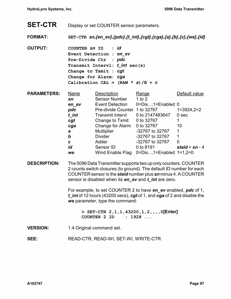
HydroLynx Systems, Inc. 5096 Data Transmitter
A102747 Page 97
SET-CTR Display or set COUNTER sensor parameters.
FORMAT: SET-CTR sn,{en_ev},{pdc},{t_int},{cgt},{cga},{a},{b},{c},{we},{id}
OUTPUT: COUNTER sn ID : idEvent Detection : en_evPre-Divide Ctr : pdcTransmit Intervl: t_int sec(s)Change to Txmit : cgtChange for Alarm: cgaCalibration CAL = (RAW * a)/b + c
PARAMETERS: Name Description Range Default valuesn Sensor Number 1 to 2en_ev Event Detection 0=Dis...,1=Enabled 0pdc Pre-divide Counter 1 to 32767 1=3924,2=2 t_int Transmit Intervl 0 to 2147483647 0 seccgt Change to Txmit 0 to 32767 1cga Change for Alarm 0 to 32767 10a Multiplier -32767 to 32767 1b Divider -32767 to 32767 1c Adder -32767 to 32767 0id Sensor ID 0 to 8191 staid + sn - 4we Wind Enable Flag 0=Dis...,1=Enabled 1=1,2=0
DESCRIPTION: The 5096 Data Transmitter supports two up only counters. COUNTER2 counts switch closures (to ground). The default ID number for eachCOUNTER sensor is the staid number plus sn minus 4. A COUNTERsensor is disabled when its en_ev and t_int are zero.
For example, to set COUNTER 2 to have en_ev enabled, pdc of 1,t_int of 12 hours (43200 secs), cgt of 1, and cga of 2 and disable thewe parameter, type the command:
> SET-CTR 2,1,1,43200,1,2,,,,0[Enter]COUNTER 2 ID : 1928 ...
VERSION: 1.4 Original command set.
SEE: READ-CTR, READ-WI, SET-WI, WRITE-CTR

5096 Data Transmitter HydroLynx Systems, Inc.
Page 98 A102747
SET-CTRRESET Display or set COUNTER sensor reset time.
FORMAT: SET_CTRRESET sn,{hh},{mm},{ss},{YYYY},{MM},{DD}
OUTPUT: COUNTER sn ID : idReset Time : hh:mm:ss YYYY/MM/DD
PARAMETERS: Name Description Range Default valuesn Sensor Number 1 to 2hh Hour 0 to 23 0 hoursmm Minute 0 to 59 0 minutesss Second 0 to 59 0 secondsYYYY Year 1970 to 2105 1970MM Month 1 to 12 1 (January)DD Day of Month 1 to 31 1
DESCRIPTION: A COUNTER sensor can be set up to have its accumulator reset to0 at a future reset time. When the 5096 Data Transmitter time isupdated and the current time is equal to or past the reset time, theCOUNTER sensor accumulator is reset to 0, the new CAL data valueis transmitted and the reset time is incremented by one year.
For example, to set the COUNTER 2 reset time to September 1, 1995at 06:30 A..M., type the command:
> SET-CTRRESET 2,06,30,00,1995,09,01[Enter]COUNTER 2 ID : 1928Reset Time : 06:30:00 1995/09/01
To disable a COUNTER sensor reset time, type the COUNTERsensor number follow by a zero alone. For example, to disable theCOUNTER 2 reset time, type the command:
> SET-CTRRESET 2,0[Enter]COUNTER 2 ID : 1928Reset Time : Disabled
VERSION: 3.3 Added command.
SEE: SET-CTR, TIME=, TIME-MODE

HydroLynx Systems, Inc. 5096 Data Transmitter
A102747 Page 99
SET-ENH Display or set the radio transmission format, selecting betweenstandard ALERT, Enhanced ALERT, and Enhanced IFLOWS format.
FORMAT: SET-ENH {enhflag}
OUTPUT: Tx format : Standard ALERT
PARAMETERS: Name Description Range Default valueenhflag Tx format 0, 1, or 2 0=Standard ALERT
1=Enh. ALERT2=Enh. IFLOWS
DESCRIPTION: The 5096 Data Transmitter supports standard ALERT, EnhancedALERT and Enhanced IFLOWS data packet formats. This commandselects which format to use for radio transmissions.
Standard ALERT uses the ASCII format for sensor IDs 0 to 99 andthe Binary format for sensor IDs 100 to 8191. Enhanced ALERTincludes a 6-bit CRC in the data packet which is used for errordetection at the receiving site. Enhanced ALERT reduces the bitstorage of the sensor ID by 1-bit to the ID range: 0 to 4095. EnhancedIFLOWS also includes a 6-bit CRC but does not reduce the sensorID range: 0 to 8191. See Drawing AC107484 in Section 6.2 for detailson these formats.
All formats have a data range of 0 to 99 for sensor IDs 0 to 99 and adata range of 0 to 2047 for sensor IDs 100 to 8191.
Note that the receiving central site computer set up must be able toreceive and decode the selected format.
For example, to set enhflag to 0 to select the Standard ALERTformat, type the command:
> SET_ENH 0[Enter]Tx format : Standard ALERT
VERSION: 1.4 Original command set.3.0 Set default format to Standard ALERT.3.4 Added Enhanced IFLOWS format.
SEE: None
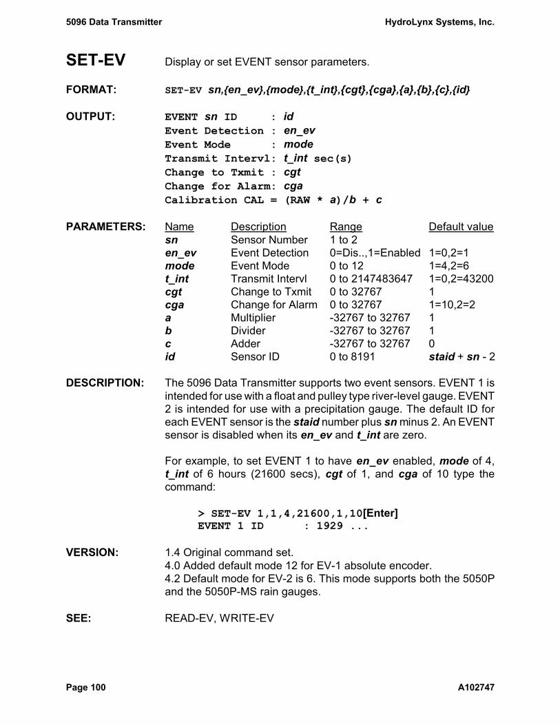
5096 Data Transmitter HydroLynx Systems, Inc.
Page 100 A102747
SET-EV Display or set EVENT sensor parameters.
FORMAT: SET-EV sn,{en_ev},{mode},{t_int},{cgt},{cga},{a},{b},{c},{id}
OUTPUT: EVENT sn ID : idEvent Detection : en_evEvent Mode : modeTransmit Intervl: t_int sec(s)Change to Txmit : cgtChange for Alarm: cgaCalibration CAL = (RAW * a)/b + c
PARAMETERS: Name Description Range Default valuesn Sensor Number 1 to 2en_ev Event Detection 0=Dis..,1=Enabled 1=0,2=1mode Event Mode 0 to 12 1=4,2=6t_int Transmit Intervl 0 to 2147483647 1=0,2=43200cgt Change to Txmit 0 to 32767 1cga Change for Alarm 0 to 32767 1=10,2=2a Multiplier -32767 to 32767 1b Divider -32767 to 32767 1c Adder -32767 to 32767 0id Sensor ID 0 to 8191 staid + sn - 2
DESCRIPTION: The 5096 Data Transmitter supports two event sensors. EVENT 1 isintended for use with a float and pulley type river-level gauge. EVENT2 is intended for use with a precipitation gauge. The default ID foreach EVENT sensor is the staid number plus sn minus 2. An EVENTsensor is disabled when its en_ev and t_int are zero.
For example, to set EVENT 1 to have en_ev enabled, mode of 4,t_int of 6 hours (21600 secs), cgt of 1, and cga of 10 type thecommand:
> SET-EV 1,1,4,21600,1,10[Enter]EVENT 1 ID : 1929 ...
VERSION: 1.4 Original command set.4.0 Added default mode 12 for EV-1 absolute encoder.4.2 Default mode for EV-2 is 6. This mode supports both the 5050Pand the 5050P-MS rain gauges.
SEE: READ-EV, WRITE-EV

HydroLynx Systems, Inc. 5096 Data Transmitter
A102747 Page 101
SET-EVRESET Display or set EVENT sensor reset time.
FORMAT: SET-EVRESET sn,{hh},{mm},{ss},{YYYY},{MM},{DD}
OUTPUT: EVENT sn ID : idReset Time : hh:mm:ss YYYY/MM/DD
PARAMETERS: Name Description Range Default valuesn Sensor Number 1 to 2hh Hour 0 to 23 0 hoursmm Minute 0 to 59 0 minutesss Second 0 to 59 0 secondsYYYY Year 1970 to 2105 1970MM Month 1 to 12 1 (January)DD Day of Month 1 to 31 1
DESCRIPTION: An EVENT sensor can be set up to have its accumulator reset to 0 ata future reset time. When the 5096 Data Transmitter time is updatedand the current time is equal to or past the reset time, the EVENTsensor accumulator is reset to 0, the new CAL data value istransmitted and the reset time is incremented by one year.
For example, to set the EVENT 2 reset time to September 1, 1995 at06:30 A.M., type the command:
> SET-EVRESET 2,08,00,00,1995,09,01[Enter]EVENT 2 ID : 1930Reset Time : 06:30:00 1995/09/01
To disable an EVENT sensor reset time, type the EVENT sensornumber follow by a zero alone. For example, to disable the EVENT 2reset time, type the command:
> SET-EVRESET 2,0[Enter]EVENT 2 ID : 1930Reset Time : Disabled
VERSION: 3.3 Added command.
SEE: SET-EV, TIME=, TIME-MODE

5096 Data Transmitter HydroLynx Systems, Inc.
Page 102 A102747
SET-HOLDOFF Display or set the transmitter hold-off time interval.
FORMAT: SET-HOLDOFF {holdoff}
OUTPUT: TX Holdoff : holdoff (secs)
PARAMETERS: Name Description Range Default valueholdoff Transmitter Holdoff 0 to 32767 20 secs
DESCRIPTION: After each transmission the transmit hold-off timer is started. Onlyalarm transmissions, which override the hold-off, are allowed duringthe hold-off interval. If a transmit condition occurs for a sensor duringthe hold-off interval, the transmission pending flag for that sensor isset. When the hold-off timer expires, current values from all sensorswith transmission pending flags will be transmitted. This featurereduces the possibility of collisions with transmissions from otherstations and helps to conserve battery power.
The transmitter hold-off time must be a multiple of the station timestep, SPT.
For example, to set holdoff to 10 seconds type the command:
> SET-HOLDOFF 10[Enter]TX Holdoff : 10 (secs)
VERSION: 1.4 Original command set.
SEE: SET-SPT
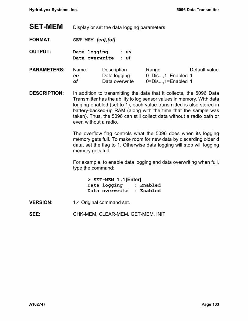
HydroLynx Systems, Inc. 5096 Data Transmitter
A102747 Page 103
SET-MEM Display or set the data logging parameters.
FORMAT: SET-MEM {en},{of}
OUTPUT: Data logging : enData overwrite : of
PARAMETERS: Name Description Range Default valueen Data logging 0=Dis...,1=Enabled 1of Data overwrite 0=Dis...,1=Enabled 1
DESCRIPTION: In addition to transmitting the data that it collects, the 5096 DataTransmitter has the ability to log sensor values in memory. With datalogging enabled (set to 1), each value transmitted is also stored inbattery-backed-up RAM (along with the time that the sample wastaken). Thus, the 5096 can still collect data without a radio path oreven without a radio.
The overflow flag controls what the 5096 does when its loggingmemory gets full. To make room for new data by discarding older ddata, set the flag to 1. Otherwise data logging will stop will loggingmemory gets full.
For example, to enable data logging and data overwriting when full,type the command:
> SET-MEM 1,1[Enter]Data logging : EnabledData overwrite : Enabled
VERSION: 1.4 Original command set.
SEE: CHK-MEM, CLEAR-MEM, GET-MEM, INIT

5096 Data Transmitter HydroLynx Systems, Inc.
Page 104 A102747
SET-PK Display or set PEAK WIND sensor parameters.
FORMAT: SET-PK sn,{s_int},{tx_int},{vgt},{vga},{a},{b},{c},{id}
OUTPUT: PEAK WIND sn ID : idSample Interval : s_int sec(s)Transmit Intervl: tx_int sec(s)Value to Txmit : vgtValue for Alarm : vgaCalibration CAL = (RAW * a)/b + c
PARAMETERS: Name Description Range Default valuesn Sensor Number 1 to 2s_int Sample Interval 0 to 2147483647 0 sectx_int Transmit Intervl 0 to 2147483647 0 secvgt Value to Transmit 0 to 32767 0vga Value for Alarm 0 to 32767 70a Multiplier -32767 to 32767 360b Divider -32767 to 32767 1308c Adder -32767 to 32767 0id Sensor ID 0 to 8191 staid + sn - 7
DESCRIPTION: A peak wind sensor is a virtual sensor in that it derives its value fromthe wind sensor. It makes several samples of wind data over itstransmit interval and transmits the largest of those values. The defaultID for each PEAK WIND sensor is the staid number plus sn minus 7.A PEAK WIND sensor is disabled when its s_int and tx_int are zero.
The PEAK WIND raw count is the maximum number of WIND sensorpre-divide counts, pdc, in a sample interval. To convert to kph, setthe a parameter to 3600 / s_int and the b parameter to the pdc perkm.
For example, to set PEAK WIND 1 to have s_int of 10 seconds,tx_int of 1 hour (3600 seconds), vgt of 0, and vga of 40 kph, type thecommand:
> SET-PK 1,10,3600,0,40,360,1308[Enter]PEAK WIND 1 ID : 1925 ...
VERSION: 1.4 Original command set.
SEE: READ-PK, SET-WI
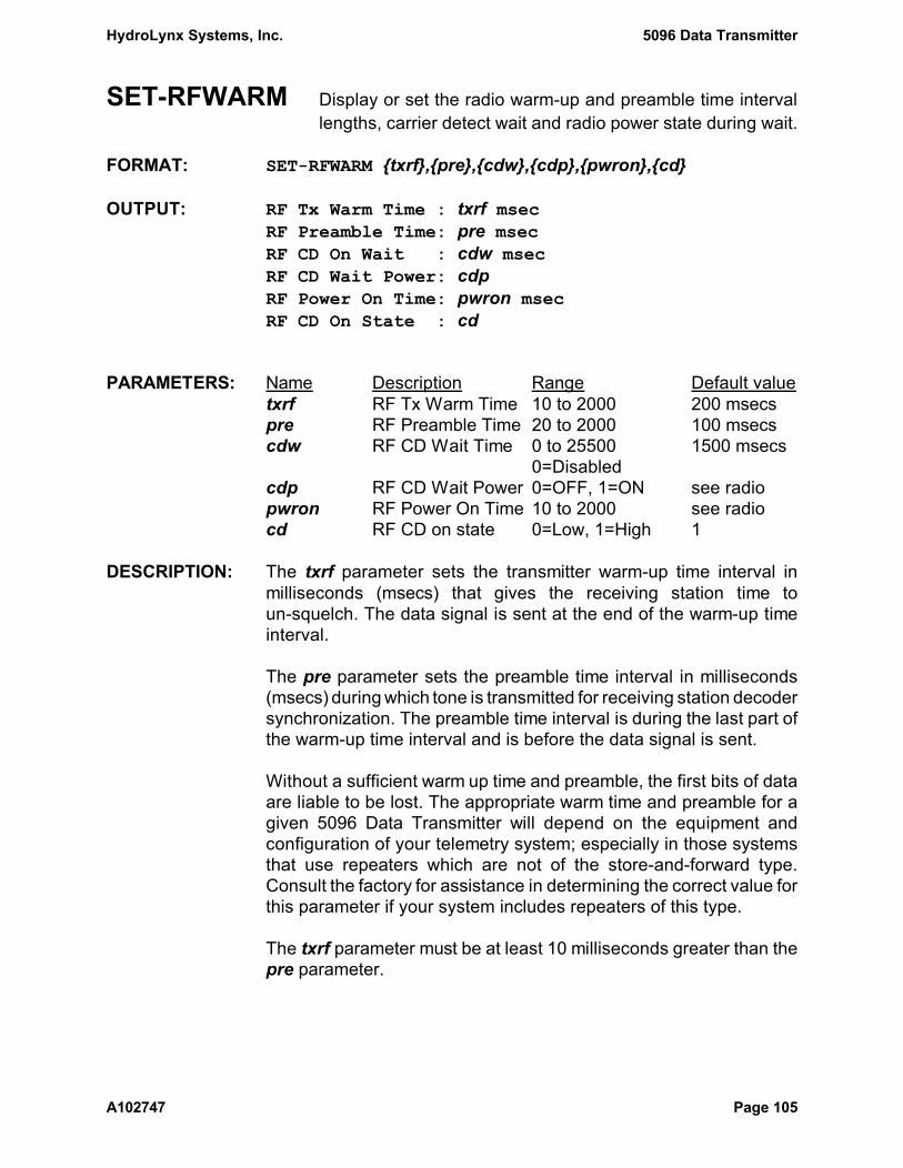
HydroLynx Systems, Inc. 5096 Data Transmitter
A102747 Page 105
SET-RFWARM Display or set the radio warm-up and preamble time intervallengths, carrier detect wait and radio power state during wait.
FORMAT: SET-RFWARM {txrf},{pre},{cdw},{cdp},{pwron},{cd}
OUTPUT: RF Tx Warm Time : txrf msecRF Preamble Time: pre msecRF CD On Wait : cdw msecRF CD Wait Power: cdpRF Power On Time: pwron msecRF CD On State : cd
PARAMETERS: Name Description Range Default valuetxrf RF Tx Warm Time 10 to 2000 200 msecspre RF Preamble Time 20 to 2000 100 msecscdw RF CD Wait Time 0 to 25500 1500 msecs
0=Disabledcdp RF CD Wait Power 0=OFF, 1=ON see radiopwron RF Power On Time 10 to 2000 see radiocd RF CD on state 0=Low, 1=High 1
DESCRIPTION: The txrf parameter sets the transmitter warm-up time interval inmilliseconds (msecs) that gives the receiving station time toun-squelch. The data signal is sent at the end of the warm-up timeinterval.
The pre parameter sets the preamble time interval in milliseconds(msecs) during which tone is transmitted for receiving station decodersynchronization. The preamble time interval is during the last part ofthe warm-up time interval and is before the data signal is sent.
Without a sufficient warm up time and preamble, the first bits of dataare liable to be lost. The appropriate warm time and preamble for agiven 5096 Data Transmitter will depend on the equipment andconfiguration of your telemetry system; especially in those systemsthat use repeaters which are not of the store-and-forward type.Consult the factory for assistance in determining the correct value forthis parameter if your system includes repeaters of this type.
The txrf parameter must be at least 10 milliseconds greater than thepre parameter.

5096 Data Transmitter HydroLynx Systems, Inc.
Page 106 A102747
The cdw parameter is the 5096 Data Transmitter carrier detectcontrol parameter. If this parameter is not zero, it sets the maximumtime the 5096 Data Transmitter will wait after detecting a radio carriersignal before forcing a data transmission.
The 5096 Data Transmitter can detect radio transmissions by othernearby transmitters or by repeaters and it will wait until the othertransmission completes before it starts its own transmission. After aradio carrier is detected, the transmitter will wait 100 milliseconds andcheck for radio carrier again before starting its own transmission. Thisdelay allows for repeaters to start transmitting after receiving atransmission from a nearby station. The radio carrier can stop andrestart up to 3 times before the transmitter forces a data transmission.
If a radio carrier signal remains on for the maximum wait time set inthe cdw parameter, a data transmission is forced. Increase themaximum wait time for systems with long transmission packets. Setcdw to 0 to disable radio carrier signal checking.
The cdp parameter determines the radio power state while waiting fora radio carrier signal to stop. If cdp is 0 (OFF) the radio power isturned off while waiting. If cdp is 1 (ON) the radio power is left on.Synthesized frequency radios will lose frequency lock when poweredoff and so should have this parameter set to 1 (ON).
The cd parameter defines the carrier detect on state for the Radiotype. If cd is 1 then a positive voltage on the carrier detect pinindicates a carrier signal. If cd is 0 then a zero voltage on the carrierdetect pin indicates a carrier signal.
The 5096 Data Transmitter firmware is delivered with the RF PowerOn Time parameter, pwron, set to match the type of radio suppliedwith the transmitter. This parameter defines the time to wait after theradio is powered on before the radio carrier signal is turned on.
Radio Type Power On Time CD Wait Power CD State(Blank) 25 msec OFF 1R & RI 800 msec ON 1
M 400 msec ON 1

HydroLynx Systems, Inc. 5096 Data Transmitter
A102747 Page 107
For example, to set the RF warm parameter txrf to 200, pre to 100,cdw to 2000 msec (2 secs), cdp to OFF, pwron to 400, and cd to 1,type:
> SET-RFWARM 200,100,2000,0,400,1[Enter]RF Tx Warm Time : 200 msecRF Preamble Time: 100 msecRF CD Wait Time : 2000 msecRF CD Wait Power: OFFRF Power On Time: 400 msecRF CD On State : 1
VERSION: 1.4 Original command set.3.0 Standardized radio parameters: 25 ms RF power on.3.3 Added RF CD Wait Time parameter and Radio type R.3.4 Added RF CD Wait Power and Power On Time parameters.3.6 Added Radio type M.4.1 Added RF CD On State parameter.
SEE: SET-SPT

5096 Data Transmitter HydroLynx Systems, Inc.
Page 108 A102747
SET-SERIAL Display or set SERIAL sensor parameters.
FORMAT: SET-SERIAL sn,{ev_th},{t_int},{s_int},{cgt},{cga},{a},{b},{c},{id}
OUTPUT: SERIAL sn ID : idEvent threshold : ev_thTransmit Intervl: t_int sec(s)Sample Interval : s_int sec(s)Change to Txmit : cgtChange for Alarm: cgaCalibration CAL = (RAW * a)/b + c
PARAMETERS: Name Description Range Default valuesn Sensor Number 1 to 7ev_th Event Threshold 0 to 32767 0t_int Transmit Intervl 0 to 2147483647 0 secs_int Sample Interval 0 to 2147483647 0 seccgt Change to Txmit 0 to 32767 1cga Change for Alarm 0 to 32767 50a Multiplier -32767 to 32767 1b Divider -32767 to 32767 4c Adder -32767 to 32767 0id Sensor ID 0 to 8191 staid + sn
DESCRIPTION: SERIAL sensors can be defined for a 5096 Data Transmitter usingthe SET-SERIAL command. SERIAL sensor data values can then besaved using the WRITE-SERIAL command.
A SERIAL sensor uses the data storage of an ANALOG sensor withthe same number so you should only define SERIAL sensors forANALOG sensor numbers that are not used. The parameter set up fora SERIAL sensor is the same as for an ANALOG sensor. Use theSET-AN command with some parameters to return the sensor numberto an ANALOG sensor type.
For example, to set SERIAL 5 to have ev_th of 0, t_int of 1 hour(3600 secs), s_int of 1 minute (60 secs), cgt of 5, cga of 50, and noconversion of the raw value type the command:
> SET-SERIAL 5,0,3600,60,5,50,1,1,0[Enter]SERIAL 5 ID : 1935 ...
VERSION: 3.6 Added command for EPROM type S.SEE: READ-SERIAL, SET-BAUD, WRITE-SERIAL
HydroLynx Systems, Inc. 5096 Data Transmitter
A102747 Page 109
SET-SPT Display or set the number of seconds per clock tick.
FORMAT: SET-SPT {spt}
OUTPUT: Seconds Per Tick: spt
PARAMETERS: Name Description Range Default valuespt Seconds per Tick 0 to 300 10
DESCRIPTION: The 5096 Data Transmitter spends most of its time in a power-conserving standby mode, which minimizes its activity. Every time thereal-time clock ticks, the 5096 wakes up to update the clock time, thetimers, and as necessary to sample sensor data, performcalibrations,and make transmissions.
This command sets the number of seconds between ticks and storesthat parameter in battery-backed-up RAM. Set longer intervals tohave the 5096 consume slightly less power, or shorter intervals tomore precisely resolve the time of a sensor's readings.
All other time-based functions in the 5096: system timers, sampleintervals, hold-off intervals, and the real-time clock's time are basedon the clock-tick interval. The intervals for each of these functionsMUST be an integer multiple of the clock-tick interval, so when youchange the clock-tick interval, the 5096 checks all intervals andmodifies them to be multiples of the clock-tick interval.
For example, to set spt to 20 seconds, type the command:
> SET-SPT 20[Enter]WARNING: Timers Being RealignedSeconds Per Tick: 20
VERSION: 1.4 Original command set.
SEE: SET-HOLDOFF, TIME=

5096 Data Transmitter HydroLynx Systems, Inc.
Page 110 A102747
SET-ST Display or set the STATUS sensor parameters.
FORMAT: SET-ST {tx0},{t_int},{s_int},{{-}tf},{{-}af},{id}
OUTPUT: STATUS sn ID : idTxmt Zero Status: tx0Transmit Intervl: t_int sec(s)Sample Interval : s_int sec(s)Change Flag : ANY (ALL) tfAlarm Flag : ANY (ALL) af
PARAMETERS: Name Description Range Default valuetx0 Transmit Zeroes 0=Dis...,1=Enabled 0t_int Transmit Intervl 0 to 2147483627 0 secs_int Sample Interval 0 to 2147483627 0 sectf Change Flag ±0 to ±11111111 +00000000af Alarm Flag ±0 to ±11111111 -11111111id Sensor ID 1 to 8191 staid - 4
DESCRIPTION: The 5096 Data Transmitter has inputs for 8 individual status lines thatare grouped for transmission and logging into a single 8-bit STATUSsensor. The default ID for the STATUS sensor is the staid numberminus 4. The STATUS sensor is disabled when its t_int and s_int arezero.
The STATUS sensor has no interrupt capability and must be read ons_int or t_int time intervals. The tx0, af, and tf parameters are usedto determine if a transmission is to be made at the s_int interval.
For example, to set the STATUS sensor to have tx0 of 1 (enabled),s_int of 10 seconds , t_int of 1 hour (3600 seconds), tf of 00000011(change on any status lines 1 and 2) and af of -00000011 (change ofall status lines 1 and 2), type the command:
> SET-ST 1,3600,10,00000011,-00000011[Enter]STATUS 1 ID : 1926 ...
VERSION: 1.4 Original command set.
SEE: READ-ST

HydroLynx Systems, Inc. 5096 Data Transmitter
A102747 Page 111
SET-WARM Display or set the wait time before reading ANALOG and STATUSsensors after turning on the switched analog power.
FORMAT: SET-WARM {wa}
OUTPUT: Analog Warm Time: wa × 10 msecs
PARAMETERS: Name Description Range Default valuewa Analog Warm Time 0 to 32767 10 except
300 type 81
DESCRIPTION: The 5096 Data Transmitter reads an ANALOG or STATUS sensor byfirst switching on the analog power supply. It waits the Analog WarmTime then takes sensor readings. This wa interval is required bymost analog sensors to have a stable output.
Enter the warm time in 10-millisecond(msecs) units. For example, toset wa to 10 (10 × 10msecs = 100msecs), type the command:
> SET-WARM 10[Enter]Analog Warm Time: 10 × 10 msecs
VERSION: 1.4 Original command set.3.9-82 Added sensor input package with 3 second default.4.1 SET-WARM no longer effects read times for status, wind directionor battery voltage.4.2 Package 81 default warm time changed to 3 seconds.
SEE: READ-AN, READ-BATT

5096 Data Transmitter HydroLynx Systems, Inc.
Page 112 A102747
SET-WI Display or set WIND sensor parameters.
FORMAT: SET-WI sn,{en_ev},{pdc},{t_int},{cgt},{cga},{a},{b},{c},{we},{id}
OUTPUT: WIND sn ID : idEvent Detection : en_evPre-Divide Ctr : pdcTransmit Intervl: t_int sec(s)Change to Txmit : cgtChange for Alarm: cgaCalibration CAL = (RAW * a)/b + c
PARAMETERS: Name Description Range Default valuesn Sensor Number 1 to 2en_ev Event Detection 0=Dis...,1=Enabled 0pdc Pre-divide Counter 1 to 32767 1=3924,2=2 t_int Transmit Intervl 0 to 2147483647 0 seccgt Change to Txmit 0 to 32767 1cga Change for Alarm 0 to 32767 10a Multiplier -32767 to 32767 1b Divider -32767 to 32767 1c Adder -32767 to 32767 0id Sensor ID 0 to 8191 staid + sn - 4we Wind Enable Flag 0=Dis...,1=Enabled 1=1,2=0
DESCRIPTION: The 5096 Data Transmitter supports two up only counters. WIND 1is intended for use with a wind sensor that produces an AC sine-wavesignal. The default ID for each WIND sensor is the staid number plussn minus 4. A WIND sensor is disabled when its en_ev and t_int arezero.
For example, to set WIND 1 to have en_ev enabled, pdc of 1308(1km), cgt of 1, and cga of 2 and enable the we parameter, type thecommand:
> SET-WI 1,1,1308,,1,2,,,,1[Enter]WIND 1 ID : 1927 ...
VERSION: 1.4 Original command set.
SEE: READ-CTR, READ-WI, SET-CTR, WRITE-CTR

HydroLynx Systems, Inc. 5096 Data Transmitter
A102747 Page 113
SHOWALL Display all sensor parameters, data values and system parameters.
FORMAT: SHOWALL {all}
OUTPUT: Real Time : Current timeStation ID : Station ID #ANALOG sn ID : Analog sn ID # ...
PARAMETERS: Name Description Range Default valueall All Sensors 0=NO,1=YES 0
DESCRIPTION: This command displays all sensor parameters, data values andsystem parameters defined in the transmitter.
By default, only the active sensor parameters and data values aredisplayed. If the all parameter is set to 1, all sensors, active andinactive have their parameters and data values displayed.
For example to display all active sensor parameters, type thecommand:
> SHOWALL[Enter]Real Time : 1994 06 01 12:35:40Station ID : 1930EVENT 1 ID : 1930Event Detection : EnabledEvent Mode : 4Transmit Intervl: 43200 sec(s)Change to Txmit : 1Change for Alarm: 2Calibration CAL = (RAW * 1)/1 + 0Reset Time : DisabledRaw Reading : 12Cal Reading : 12Analog Warm Time: 10 × 10 msecsRF Tx Warm Time : 200 msecRF Preamble Time: 100 msecRF CD Wait Time : 1500 msecRF CD Wait Power: OFFRF Power On Time: 25 msec
VERSION: 3.2 Added command.
SEE: All other commands

5096 Data Transmitter HydroLynx Systems, Inc.
Page 114 A102747
TEST Executes a test of the transmitter.
FORMAT: TEST {level},{defaultlevel}
OUTPUT: Level 1 testTransmitting all Active Sensors(Active sensor values at current time printed)(Level 2 test output displayed)
PARAMETERS: Name Description Range Default valuelevel Test level 1-2 defaultdefaultlevel Default test level 1-2 2
DESCRIPTION: This command transmits all active sensor values for the Level 1 testand checks the 5096 Data Transmitter for the Level 2 test. Thecommand functions as if the TEST switch was pressed.
The TEST command with no arguments performs the default testlevel. When initialized a 5096 Data Transmitter performs a levels 2test by default. The level parameter selects the test level. Thedefaultlevel parameter sets the default test level. Changing thedefault test level effects the TEST switch level as well as the TESTcommand level.
For example to set the default test level to 1, type the command::
> TEST ,1[Enter]
To execute a Level 2 test (time mode is set to Real Time), type thecommand::
> TEST 2[Enter]Transmitting all Active Sensors# 1930 1994 06 01 12 41 40 0012 ...Level I tests being performedROM test : PassedRAM test : PassedBATTERY test: Passed - Battery level = 13.21 vCLOCK test : Passed - drift = 1 secs/dayTEST-TX NO TONE
VERSION: 3.2 Added command.3.3 Added TEST-TX NO TONE.3.8 Added test level command parameters
SEE: None

HydroLynx Systems, Inc. 5096 Data Transmitter
A102747 Page 115
TEST-TX Turn-on the radio transmitter so you can check the radio's signalstrength and frequency.
FORMAT: TEST-TX {testtone}
OUTPUT: (None to console)(Test transmission to radio)
PARAMETERS: Name Description Range Default valuetesttone Tone transmitted 0=High and low 0
1=No tone2=High tone only3=Low tone only
DESCRIPTION: This command sends a 5 second test radio transmission. Settesttone to 0 to transmit a test signal with alternating high and lowtones. Set testtone to 1 to key on the radio without transmitting atesttone to 2 to transmit the high tone only. Set testtone to 3 totransmit the low tone only.
For example, to test the transmitter radio without tone set testtone to1, type the command:
> TEST-TX 1[Enter]
VERSION: 3.2 Added command.4.3 Added testtone parameters 2 and 3 to transmit high or low tone.
SEE: None

5096 Data Transmitter HydroLynx Systems, Inc.
Page 116 A102747
TIME-MODE Display or set the time-keeping mode to either Real or Elapsed Time.
FORMAT: TIME-MODE {tmode}
OUTPUT: Time Mode : Real Time (Elapsed Time)
PARAMETERS: Name Description Range Default valuetmode Time Mode Flag 0=Real Time, 0
1=Elapsed Time
DESCRIPTION: When tmode is set to 0 (Real Time), time is displayed as the year,month, day, hour, minute, and second.
When tmode is set to 1 (Elapsed Time), the time is displayed as thenumber of days, hours, minutes, and seconds that have elapsedsince the time was set with the TIME= command.
For example, to set tmode to Elapsed Time, type the command:
> TIME-MODE 1[Enter]Time Mode : Elapsed Time
VERSION: 1.4 Original command set.
SEE: GET-MEM, TIME=

HydroLynx Systems, Inc. 5096 Data Transmitter
A102747 Page 117
TIME= Display or set the transmitter clock time.
FORMAT: There are two formats for this command depending on the time mode.
In the Real Time mode the format is:TIME = {hh},{mm},{ss},{YYYY},{MM},{DD}
In Elapsed Time mode the format is:TIME = {hh},{mm},{ss},{ddd}
OUTPUT: The form of the output depends on the time mode.
In the Real Time mode the output is:Real Time : hh:mm:ss YYYY/MM/DD
In Elapsed Time mode the output is:Elapsed Time : ddd hh:mm:ss
PARAMETERS: Name Description Range Default valuehh Hour 0 to 23 0 hoursmm Minute 0 to 59 0 minutesss Second 0 to 59 0 secondsYYYY Year 1970 to 2105 1970MM Month 1 to 12 1 (January)DD Day of Month 1 to 31 1ddd Elapsed Days 0 to 49710 0
DESCRIPTION: The real time clock continuously increments the time every clock tickas long as the 5096 Data Transmitter is powered. The clock time isnot reset when the main battery power is disconnected but the timewill no longer increment.
The time entered must be a multiple of the clock tick step.
The format for time display depends on the TIME-MODE parameter.For example, to set the time in Real Time mode to June 1, 1994 at12:41 P.M., type the command:
> TIME = 12,41,00,1994,06,01[Enter]Real Time : 12:41:00 1994/06/01
VERSION: 1.4 Original command set.
SEE: SET-SPT, TIME-MODE

5096 Data Transmitter HydroLynx Systems, Inc.
Page 118 A102747
WRITE-CTR Set the RAW value of a COUNTER sensor.
FORMAT: WRITE-CTR sn,val
OUTPUT: COUNTER sn ID : idRaw Reading : rawCal Reading : cal
PARAMETERS: Name Description Rangesn Sensor Number 1 to 2val Value to Set 0 to 2047id Sensor ID 1 to 8191raw Raw Reading 0 to 2047cal Cal Reading 0 to 2047
DESCRIPTION: This command will set a COUNTER sensor's accumulator to anyvalue within range. Note that you will be entering the RAWaccumulator value.
This command is useful after field maintenance or testing. Forexample, if a tipping bucket has been tipped by hand (or the INITcommand has been used), you can reset the sensor to the correctnumber of bucket tips.
For example, to zero the COUNTER 2 RAW accumulator, type thecommand:
> WRITE-CTR 2,0[Enter]COUNTER 2 ID : 1928Raw Reading : 0Cal Reading : 0
VERSION: 1.4 Original command set.
SEE: INIT, READ-CTR, READ-EV, WRITE-EV

HydroLynx Systems, Inc. 5096 Data Transmitter
A102747 Page 119
WRITE-EV Set raw value of an EVENT sensor.
FORMAT: WRITE-EV sn,val
OUTPUT: EVENT sn ID : idRaw Reading : rawCal Reading : cal
PARAMETERS: Name Description Rangesn Sensor Number 1 to 2val Value to Set 0 to 2047id Sensor ID 1 to 8191raw Raw Reading 0 to 2047cal Cal Reading 0 to 2047
DESCRIPTION: This command will set an EVENT sensor's accumulator to any valuewithin range. Note that you will be entering the RAW accumulatorvalue.
This command is useful after field maintenance or testing. Forexample, if a tipping bucket has been tipped by hand (or the INITcommand has been used), you can reset the sensor to the correctnumber of bucket tips.
For example, to set the EVENT 1 RAW accumulator to 113, type thecommand:
> WRITE-EV 1,113[Enter]EVENT 1 ID : 1929Raw Reading : 113Cal Reading : 113
VERSION: 1.4 Original command set.
SEE: INIT, READ-CTR, READ-EV, WRITE-CTR

5096 Data Transmitter HydroLynx Systems, Inc.
Page 120 A102747
WRITE-SERIAL Set raw value of a SERIAL sensor.
FORMAT: WRITE-SERIAL sn,val
OUTPUT: SERIAL sn ID : idRaw Reading : rawCal Reading : cal
PARAMETERS: Name Description Rangesn Sensor Number 1 to 8val Value to Set 0 to 2047id Sensor ID 1 to 8191raw Raw Reading 0 to 2047cal Cal Reading 0 to 2047
DESCRIPTION: This command will set a SERIAL sensor's data to any value withinrange. Note that you will be entering the RAW value.
This command is the only way to enter a data value for a SERIALsensor.
Note that the SERIAL sensor must be defined by the SET-SERIALcommand before its data value can be written.
For example, to set the SERIAL 5 RAW accumulator to 100, type thecommand:
> WRITE-SERIAL 5,100[Enter]EVENT 1 ID : 1935Raw Reading : 100Cal Reading : 100
VERSION: 3.6 Added command for EPROM type S.
SEE: READ-SERIAL, SET-SERIAL

HydroLynx Systems, Inc. 5096 Data Transmitter
A102747 Page 121
i4.8 Parameter Descriptions
a, b, c Calibration Coefficients
The 5096 Data Transmitter uses three calibration coefficients to scale andoffset the RAW value of an ANALOG, EVENT, COUNTER, WIND or PEAKWIND sensor prior to transmission and logging. The Raw Reading is theactual reading obtained from the sensor (the ADC reading for an ANALOGsensor and the accumulator value for an EVENT, COUNTER, WIND orPEAK WIND sensor).
The calibration formula is:CAL = ((RAW × a)/b) + c
These parameters must be entered as integers. Decimals and fractions arenot allowed. (The RAW and CAL values are also always integers.)
All Raw Readings are converted by this formula prior to comparison with theChange for Alarm, cga, and Change to Txmit, cgt, parameters prior totransmission and logging.
The range of the transmitted values is 0 to 2047. This is fixed by the 11-bitALERT format. Any calibrated values outside this range will have only their11 least-significant bits transmitted.
all All Sensors
This parameter allows the display of all Active and Inactive sensors when setto one in the SHOWALL command. By default, only Active sensors aredisplayed.
baud Baud Rate
This parameter sets the console baud rate. Valid baud rates are 300, 1200,2400, 4800, and 9600. The default baud rate is 300.
cal Cal Reading
The 5096 Data Transmitter reads raw (RAW) sensor values, calibrates thevalues using sensor calibration coefficients and transmits the calculated(CAL) data to the central site. Sensor calibration coefficients can be used tocalculate CAL data in engineering units. Both the RAW and CAL datavalues are integers (no decimal point).
5096 Data Transmitter HydroLynx Systems, Inc.
Page 122 A102747
cd RF CD On State
Radio carrier detect state when checking for carrier signal. A value of 0 is alow state and a value of 1 is a high state.
cdp RF CD Wait Power
Radio power state when waiting for a radio carrier signal to stop. A value of0 turns off radio power while waiting and a value of 1 leaves radio power on.
cdw RF CD Wait Time
Maximum wait time in milliseconds before forcing a data transmission whena radio carrier signal is detected. A wait time of 0 disables the radio carriersignal checking.
cga Change for Alarm
For ANALOG, EVENT, COUNTER or WIND sensors this parameter sets thesensor's CAL value change from its last transmitted value for the 5096 DataTransmitter to do an alarm transmission. An alarm transmission is sentbefore other pending transmissions. It can be sent during the transmissionhold-off interval. An alarm transmission will be repeated by a normaltransmission if it occurs during a hold-off interval.
The change for alarm parameter is effective for the sensor Sample Interval,s_int, and EVENT, COUNTER and WIND sensor events. It does not effecttransmit intervals for these sensors.
cgt Change to Txmit
For ANALOG, EVENT, COUNTER or WIND sensors this parameter sets thesensor's CAL value change from its last transmitted value for the 5096 DataTransmitter to do a normal transmission. A normal transmission is sent assoon as the transmission hold-off interval is cleared.
The change to txmit parameter is effective for the sensor Sample Interval,s_int, and EVENT, COUNTER and WIND sensor events. It does not effecttransmit intervals for these sensors.
D1 Start Day (Real Time)
Starting day for the GET-MEM command when the transmitter is in RealTime mode. Values can range from 1 to 31 with a default of 1.

HydroLynx Systems, Inc. 5096 Data Transmitter
A102747 Page 123
D2 End Day (Real Time)
Ending day for the GET-MEM command when the transmitter is in Real Timemode. Values can range from 1 to 31 with a default of 31.
DD Day of Month (Real Time)
Transmitter time day number set by the TIME= command when thetransmitter is in Real Time mode. Values can range from 1 to 31. The defaultis no change.
DD1 Start Day (Elapsed Time)
Starting day for the GET-MEM command when the transmitter is in ElapsedTime mode. Values can range from 0 to 49710 with a default of 0.
DD2 End Day (Elapsed Time)
Ending day for the GET-MEM command when the transmitter is in ElapsedTime mode. Values can range from 0 to 49710 with a default of 49710.
ddd Elapsed Days (Elapsed Time)
Transmitter time elapsed day number set by the TIME= command when thetransmitter is in Elapsed Time mode. Values can range from 0 to 49710. Thedefault is no change.
defaultlevel Default test level
Sets the default test level for when the TEST switch is pressed or the TESTcommand is entered with no test level parameter (see level).
en Data Logging Enable Flag
When enabled with the SET-MEM command, this parameter allows sensordata to be logged in memory. Set this parameter to 1 to enable, 0 to disabledata logging. Changing this parameter value will not effect data currentlylogged in memory.
en_ev Event Detection Flag
This flag for the EVENT, COUNTER and WIND sensors enables (disables)transmission on an event basis. When this flag is enabled and the sensoraccumulator is incremented or decremented by an event trigger, the CALdata is checked against the Change for Alarm, cga, and Change to Txmit,cgt, parameters. If these parameter conditions are met, the sensor data istransmitted and logged. When this flag is disabled, the sensor reading is still

5096 Data Transmitter HydroLynx Systems, Inc.
Page 124 A102747
incremented or decremented but the data value is not transmitted or loggedunless a Transmit Intervl, t_int, is defined.
enhflag Tx format
The 5096 Data Transmitter will transmit radio data in the format selected bythis parameter. The formats are 0 = Standard ALERT, 1 = Enhanced ALERTand 2 = Enhanced IFLOWS format.
Standard ALERT uses the ASCII format for sensor IDs 0 to 99 and theBinary format for sensor IDs 100 to 8191. Enhanced ALERT includes a 6-bitCRC in the data packet which is used for error detection at the receiving site.Enhanced ALERT reduces the bit storage of the sensor ID by 1-bit to the IDrange: 0 to 4095. Enhanced IFLOWS also includes a 6-bit CRC but does notreduce the sensor ID range: 0 to 8191. See Drawing AC107484 in Section6.2 for details on these formats.
All formats have a data range of 0 to 99 for sensor IDs 0 to 99 and a datarange of 0 to 2047 for sensor IDs 100 to 8191.
ev_th Event Threshold
This parameter sets a minimum CAL data value an ANALOG sensor mustreach before readings taken at the Sample Interval, s_int, meeting theChange for Alarm, cga, or Change to Txmit, cgt, criteria will betransmitted or logged. Readings taken at the Transmit Intervl, t_int, are noteffected by this parameter.
h1 Start Hour
Starting hour for the GET-MEM command when the transmitter is in eithertime mode. Values can range from 0 to 23 with a default of 0.
h2 End Hour
Ending hour for the GET-MEM command when the transmitter is in eithertime mode. Values can range from 0 to 23 with a default of 23.
hh Hour
Transmitter time hour number set by the TIME= command when thetransmitter is in either time mode. Values can range from 0 to 23. The defaultis no change.

HydroLynx Systems, Inc. 5096 Data Transmitter
A102747 Page 125
holdoff Transmitter Holdoff
After each transmission, the transmit hold-off timer is started. Except foralarm transmissions, which override the hold-off timer, no transmissions areallowed during the hold-off interval. This includes both sensor and testtransmissions. The hold-off timer reduces the possibility of collisions withtransmissions from other stations and helps to conserve battery power.
If a transmit condition occurs for a sensor during the hold-off interval, thesensor data value is logged but its transmission is delayed until the hold-offtimer expires. After the hold-off timer expires, the current sensor reading (notnecessarily the reading when the transmit condition occurred) is transmitted.
The transmitter hold-off parameter is entered in seconds with a range of 0(No hold-off) to 32767 seconds. The default is 20 seconds.
id Sensor ID
The sensor ID is a number that uniquely identifies a sensor to the receivingbase station. Each data transmission includes the sensor ID. Logged dataincludes the sensor ID.
The 5096 Data Transmitter provides default sensor IDs that are calculatedfrom the staid read from the switch positions. The SET... commands canchange a sensor's ID to any unused ID.
NOTE: The 5096 Data Transmitter will not allow duplicate sensor IDs to beentered into the transmitter for active sensors; an error message willbe displayed. The system operator must verify that there are noduplicate sensor ID assignments in the ALERT network.
See Section 3.3.1 for default sensor ID offsets from the staid.
level Test level
Test level 1 transmits all active sensors. Test level 2 transmits a 5 secondtest tone after the active sensors are transmitted. Then it tests the 5096 DataTransmitter ROM, RAM, battery sensor under load, and clock drift. The level2 test ends by transmitting no tone for 5 seconds.

5096 Data Transmitter HydroLynx Systems, Inc.
Page 126 A102747
M1 Start Month
Starting month for the GET-MEM command when the transmitter is in RealTime mode. Values can range from 1 to 12 with a default of 1.
M2 End Month
Ending month for the GET-MEM command when the transmitter is in RealTime mode. Values can range from 1 to 12 with a default of 12.
MM Month
Transmitter time month number set by the TIME= command when thetransmitter is in Real Time mode. Values can range from 1 to 12. The defaultis no change.
m1 Start Minute
Starting minute for the GET-MEM command when the transmitter is in eithertime mode. Values can range from 0 to 59 with a default of 0.
m2 End Minute
Ending minute for the GET-MEM command when the transmitter is in eithertime mode. Values can range from 0 to 59 with a default of 59.
ma Total Memory
The total memory available for data logging is displayed by CHK-MEM. Thetotal memory is measured in bytes.
mm Minute
Transmitter time minute number set by the TIME= command when thetransmitter is in either time mode. Values can range from 0 to 59. The defaultis no change.
mode Event Mode
The Event Mode defines how the accumulator value for an EVENT sensoris effected by the trigger and status inputs. Where the table indicates NO forTrig on A or Trig on B, that corresponding trigger input is tied low. Where thetable indicate YES for both Trig on A and Trig on B, the sensor is acomplementary type (i.e. Trig on A = normally open contact, Trig on B =normally closed contact). INCR indicates that the accumulator will beincremented and DECR indicates that the accumulator will be decremented.Match the mode to the sensor type you will connect to this sensor input.

HydroLynx Systems, Inc. 5096 Data Transmitter
A102747 Page 127
Starting with version 4.2, mode 6 is the default mode for EV-2. Mode 6supports both the 5050P and 5050P-MS rain gauges. A 5050P-MS buckettip sends a momentary pulse which causes two trigger line state changes.Under mode 4, the accumulator is incremented twice. Event Mode 6instructs the 5096 Data Transmitter to only increment the accumulator oncewhen two trigger line state changes are less than 200 milliseconds apart.
WARNING: Before connecting a 5050LLFT liquid level sensor or a 5050TS testswitch to the 5096 Data Transmitter, check the wiring of the sensorcable connector. Open the female MS connector at the cable end andcut off any wire that may be attached to pin B. Reassemble theconnector when finished.
This action is required to prevent damage to the 5096 Data Transmitter.
MODE TABLEA Trig Trig on B On Status On Status Sensor
Mode Pulse Pulse Low High Type 0 YES NO INCR DECR 5050OE1 YES NO DECR INCR 5050OE2 YES NO INCR INCR 2500, 25013 YES NO DECR DECR4 YES YES INCR DECR 5050LLFT,
5050ELFT,5050EL,5050P
5 YES YES DECR INCR 5050LLFT,5050ELFT
6 YES YES INCR INCR 5050P,5050P-MS
7 YES YES DECR DECR8 NO YES INCR DECR9 NO YES DECR INCR
10 NO YES INCR INCR11 NO YES DECR DECR12 ---- ---- ---- ---- Absolute Encoder
mu Used Memory
The memory used for data logging is displayed by CHK-MEM. The usedmemory is measured in bytes.
Logged sensor data reports use 2 bytes for timed reports, 6 bytes for eventreports and 8 bytes for non-aligned timed or event reports.
For example, if the station was logging timed reports every hour for 1 month

5096 Data Transmitter HydroLynx Systems, Inc.
Page 128 A102747
for 3 sensors (24hours * 31days * 3sensor * 2bytes) and 25 event reportswere logged (25event * 6bytes), the CHK-MEM command would display4614 bytes used.
of Overflow Flag
When enabled with the SET-MEM command, this parameter will cause newdata to overwrite the oldest data when logging memory is full. Whendisabled, data logging stops when logging memory is full. Set this parameterto 1 to enable, 0 to disable overwriting when logging memory if full.
pct Percent Used
The percent of memory used for data logging is displayed by CHK-MEM.The percent of memory is computed from Used Memory / Total Memory *100.
For example, if the Total Memory available is 24576 bytes, and the UsedMemory is 4614 bytes, the Percent Used displays 18.77%
pdc Pre-Divide Counter
The number of input pulses required by a COUNTER or WIND sensor toincrement the accumulator value by one unit and generate an event triggerinterrupt.
pn Sensor Input Package Part Number
Part number extensions 54, 80, 81, 82, 90, N and S define the sensor inputpackage supported by the 5096 Data Transmitter firmware. (See Section1.4)
pre RF Preamble Time
The number of milliseconds the transmitter will generate its preamble signalbefore it starts transmitting sensor data signals. The preamble signal startsafter (txrf - pre) milliseconds in the RF warm time interval.
pwron RF Power On Time
The number of milliseconds the transmitter will wait after turning on the radiopower before it sends the carrier signal. This time allows the radio to warmup and lock on frequency.

HydroLynx Systems, Inc. 5096 Data Transmitter
A102747 Page 129
R Radio Type
Indicates the default radio type parameters used by this EPROM version.Radio
Type Power On Time CD Wait Power CD State(Blank) 25 msec OFF 1R & RI 800 msec ON 1
M 400 msec ON 1
raw Raw Reading
The 5096 Data Transmitter reads raw (RAW) sensor values, calibrates thevalues using sensor calibration coefficients and transmits the calculated(CAL) data to the central site. Both the RAW and CAL data values areintegers (no decimal point).
rcnt Reset Count
The count of the number of Resets at the station since the count was lastinitialized.
rstate Reset Initialize State
Set the Initialize on TEST-RESET parameter state to 0 = Off (Disabled) or1 = On (Enabled). When the Initialize on TEST-RESET parameter isenabled, the station will execute an INIT command if the TEST switch is helddown when the RESET switch is pressed.
s_int Sample Interval
This parameter is used to set the interval in seconds between successivereads for the specified sensor. Each sensor has its own sample intervalwhich can be set independently from others. Sample intervals for all sensorscan be aligned with each other using the ALIGN command.
When s_int is set to 0 this feature is disabled. When the sample interval isnon-zero the sensor will be read every s_int seconds.
For ANALOG sensors, the CAL data value is compared to the EventThreshold, ev_th, the Change for Alarm, cga, and Change to Txmit, cgt,parameters. If these parameter conditions are met, the sensor data istransmitted and logged.

5096 Data Transmitter HydroLynx Systems, Inc.
Page 130 A102747
For PEAK WIND sensors, the current wind run count is compared to the lastcount and the maximum of these two counts is saved. At the TransmitInterval, tx_int, the maximum wind run count is transmitted and logged if thePEAK WIND Value for Alarm, vga, or Value to Transmit, vgt, criteria aremet.
For STATUS sensors, the current status reading is compared to theTransmit zeroes, tx0, Alarm Flag, af, and Change Flag, tf, criteria. If thecriteria conditions are met, the data value is transmitted and logged.
sn Sensor Number
The sensor number parameter is used with the sensor READ..., SET... andWRITE... commands to identify which ANALOG, EVENT, COUNTER, WINDor PEAK WIND sensor is to be used. The sensor number range variesdepending on the sensor type.
The sensor number is NOT the id number.
spt Seconds Per Tick
The number of seconds between each clock interrupt which allows themicro-processor to increment the real time clock and decrement timers. Alltime interval parameters must be multiples of the spt parameter.
ss Second
Transmitter time seconds number set by the TIME= command when thetransmitter is in either time mode. Values can range from 0 to 59. The defaultis no change.
staid Station ID
The Station ID is read from the ID switches when the 5096 Data Transmitterprogram starts and is also displayed by the READ-IDSW or SHOWALLcommands.
string Search String
The HELP command will display the command names and parameter list forcommands that start with the search string characters. Up to 8 characterscan be entered for the search string. If no string is entered, all commandsare displayed.

HydroLynx Systems, Inc. 5096 Data Transmitter
A102747 Page 131
testtone Test transmit tone
Used by the TEST-TX command to set the tone transmitted during the test.Value Transmit tone
0 Alternating high and low tones1 No tones2 High tone3 Low tone
tf, af Status Change and Alarm Flags
The STATUS sensor CAL data is transmitted on the time interval set in theSample Interval, s_int, parameter when the Txmt Zero Status, tx0, flagcriteria and the Alarm Flag, af, or Change Flag, tf, criteria are met. The CALdata is transmitted on the time interval set in the Transmit Intervl, t_int,transmissions regardless of any status line state change or flag criteria.
The Alarm Flag and Change Flag parameters mark which status lines aremonitored for changes in state. The flag parameters can be set to monitorchanges in state for ANY or ALL marked status lines. The flag criteria is metfor ANY when any marked status line changes state; the flag criteria is metfor ALL when all marked status lines change state. The flag criteria is metregardless of any status line state change when either parameter is set to00000000 (the tx0 flag criteria must still be met to transmit).
The change and alarm flags are signed 8 digit binary numbers. Each digit isused to mark whether or not a status line is monitored for changes in state.The rightmost digit marks status line 1 and the leftmost digit marks statusline 8. If the digit is 1 the status line is monitor; If the digit is 0 the status lineis ignored. When a minus sign (-) is typed before the binary number, ALLstatus lines marked must change in state to cause a transmission. When aplus sign (+) or no sign is typed ANY status line marked can change in stateto cause a transmission.
tmode Time Mode Flag
This parameter sets the time mode to Real Time when set to 0 and ElapsedTime when set to 1 by the command TIME-MODE.
When the time mode is Real Time, the time is displayed as the year, month,day, hour, minute and second. When the time mode is Elapsed Time, thetime is displayed as the number of days, hours, minutes and seconds thathave elapsed since the time was set with the TIME= command.
5096 Data Transmitter HydroLynx Systems, Inc.
Page 132 A102747
txrf RF Tx Warm Time
The number of milliseconds the transmitter will send a carrier signal beforeit starts transmitting sensor data signals.
t_int Transmit Intervl
This parameter sets the interval in seconds between transmissions of sensorreadings regardless of change or threshold parameters. Each sensor has itsown transmit interval which can be set independently from others. Thetransmit intervals for all sensors can be aligned with each other using theALIGN command.
When t_int is set to 0 this feature is disabled. When the Transmit Intervlis non-zero the sensor will be read and its data value will be transmitted andlogged every t_int seconds. Transmissions at the transmit interval areeffected by the transmission hold-off timer.
tx_int Transmit Interval (PEAK WIND)
This parameter sets the interval in seconds between transmissions of aPEAK WIND sensor's readings. Each PEAK WIND sensor has its owntransmit interval which can be set independently from others. The transmitintervals for all sensors can be aligned with each other using the ALIGNcommand.
When tx_int is set to 0 this feature is disabled. When the Transmit Intervalis non-zero the maximum wind run count is checked against the Value forAlarm, vga, and Value to Transmit, vgt, parameters every tx_int seconds.If the parameter conditions are met, the sensor data is transmitted andlogged. Transmissions at the transmit interval are effected by thetransmission hold-off timer.
tx0 Transmit Zero Status
When enabled, this flag allows the transmission of zero status values. Whendisabled, the status value must be non-zero to transmit. Set this parameterto 1 to enable, 0 to disable zero status value transmissions.
val Value to Set
This is the EVENT or COUNTER sensor accumulator value to set by theWRITE-EV or WRITE-CTR commands. This is the sensor RAW value. Thevalue range is 0 to 2047.

HydroLynx Systems, Inc. 5096 Data Transmitter
A102747 Page 133
ver Firmware Version Number
5096 Data Transmitter firmware version. See Section 6.3 for a list offirmware versions. Always check for the latest firmware version and relateddocumentation whenever the 5096 Data Transmitter is to be programmed.
vga Value for Alarmvgt Value to Transmit
These parameters are used by the PEAK WIND sensor to determine whetheran alarm or normal transmission is to be made at the Transmit Interval,tx_int.
At the transmit interval, when the PEAK WIND CAL data is greater than orequal to the vga parameter an alarm transmission is made. Otherwise, whenthe CAL data is greater than or equal to the vgt parameter a normaltransmission is made (or set pending if the transmit hold-off is in effect).
wa Analog Warm Time
This parameter sets the time to wait (in 10 millisecond counts) after turningon the switched analog power before reading ANALOG sensors. The warmtime does not effect status, wind direction or battery voltage.
wcal Wind Run Cal Reading
The wind run calibrated reading displayed by the READ-WI command showsthe lower 5 bits of the WIND CAL data.
wdir Wind Direction Reading
Wind direction reading displayed by the READ-WI command shows theupper 6 bits of the wind direction sensor (ANALOG 7) CAL data.
we Wind Enable Flag
This parameter enables a COUNTER sensor to become a WIND sensor.WIND sensors transmit data in the ALERT Wind format. This formatcombines the wind run count and the wind direction. A value of 1 enables aWIND sensor. A value of 0 disables a WIND sensor, leaving the input as aCOUNTER sensor.
wind Combined Wind Reading
The Combined wind reading displayed by the READ-WI command shows theWIND data in ALERT Wind format which is the Wind Run Cal Readingshifted left 6 bits and ored with the Wind Direction Reading.

5096 Data Transmitter HydroLynx Systems, Inc.
Page 134 A102747
YYY1 Start Year
Starting year for the GET-MEM command when the transmitter is in RealTime mode. Values can range from 1970 to 2105 with a default of 1970.
YYY2 End Year
Ending year for the GET-MEM command when the transmitter is in RealTime mode. Values can range from 1970 to 2105 with a default of 2105.
YYYY Year
Transmitter time year number set by the TIME= command in Real Timemode. Values can range from 1970 to 2105. The default is no change.

HydroLynx Systems, Inc. 5096 Data Transmitter
A102747 Page 135
4.9 ERROR Messages
1: No such command
The command typed is not supported by the 5096 Data Transmitter. Checkyour spelling and the firmware version type and number. Use HELP to getthe correct command spelling and a list of commands.
2: Parameter out of range
The value typed for one or more parameters exceeds the limits for theparameter. Consult the manual under the command description. Check yourcommand parameter positioning. Did you type enough commas to separateor skip over parameters?
3: Parameter format wrong
The parameter cannot be interpreted as typed. This error would normally bedisplayed if a non-numerical was typed in a numerical parameter. Consultthe manual under the command description. Check your commandparameter positioning. Did you type enough commas to separate or skipover parameters?
4: Wrong number of parameters
Either a required parameter has been omitted or too many parameters havebeen typed for the command. Consult the manual under the commanddescription. Check your command parameter positioning. Did you typeenough commas to separate or skip over parameters?
5: ID already exists
An attempt was made to set a sensor's ID number to one that is alreadyassigned to another active sensor. Type the SHOWALL command to list theactive sensors and their assigned ID numbers.
6. Invalid request for an absolute encoder
The WRITE-EV command cannot be used on a absolute encoder sensor.
7. Sensor type is not analog
The READ-AN command cannot be used on an ANALOG sensor numberassigned to a SERIAL sensor.

5096 Data Transmitter HydroLynx Systems, Inc.
Page 136 A102747
8. Sensor type is not serial
The READ-SERIAL or WRITE-SERIAL commands cannot be used on anSERIAL sensor that has not been defined by the SET-SERIAL command.
9. Sample interval must be modulo the transmit interval
A sample interval divide evenly into the transmit interval.
HydroLynx Systems, Inc. 5096 Data Transmitter
A102747 Page 137
5 Maintenance, Testing and Troubleshooting
5.1 Maintenance 1385.1.1 Station Check 1385.1.2 Battery 1385.1.3 Silica Gel 1385.1.4 Sensor Maintenance 1395.1.5 Radio Maintenance 139
5.2 Testing 1405.2.1 Power-up Test 1405.2.2 Level 1 Test 1405.2.3 Level 2 Test 1415.2.4 Level 3 Test 142
5.3 Troubleshooting 1435.3.1 Battery Failures 1435.3.2 Sensor Failures 1445.3.3 Transmission Failures 144
5.4 Troubleshooting with the Console 1455.4.1 TEST Sequence 1455.4.2 READ-BATT Command 1455.4.3 READ Commands 1465.4.4 GET-MEM and Time of Failure 1465.4.5 SHOWALL Command 1465.4.6 SET Commands 1465.4.7 Signal Input Protection 1465.4.8 Tipping Bucket and Transmitter 1465.4.9 ANALOG Sensors 1475.4.10 SET-WARM and ANALOG Sensors 1475.4.11 RFWARM and the Transmitter 1475.4.12 RESETCNT Command 1485.4.13 INIT and Default Settings 148

5096 Data Transmitter HydroLynx Systems, Inc.
Page 138 A102747
5.1 Maintenance
The 5096 Data Transmitter is designed for long term use with a minimum of maintenance.HydroLynx Systems recommends that there should be visits to the site at least twice a yearto perform routine maintenance and to check the battery. Visits should be scheduled priorto seasonal rainy periods. Whenever a site is to be visited for either service ormaintenance, HydroLynx Systems recommends keeping a record describing the purposeof the visit and the maintenance performed. This information can be helpful on future visits.An example of a Maintenance Report form can be found in Section 6.2, Document numberA104973.
5.1.1 Station Check
Any visit to the station site should include a visual inspection of all exposed hardware andcables to locate damage or wear due to severe weather conditions. Check all of the cablesand connectors to ensure that there has been no damage. Check closely any cables thatmay have been whipped by the wind, looking for bare wires next to any adjacentstructures. Check the connectors for corrosion. Check the forward and reverse power ofthe antenna and antenna cable by using a wattmeter. If the antenna is a directionalantenna, check the mounting to ensure that the antenna is still pointed in the correctdirection. Replace any cables and connectors that have been damaged to avoid futuresystem failures.
5.1.2 Battery
Replace the system battery with a freshly charged one, at least once yearly (twice a yearfor the 7AH battery in the 5096N). Batteries in rain gauges should be replaced just beforethe rainy season begins. Always maintain a fully charged battery for immediate placementinto the system should the system battery become weak or fail entirely. For systems withmultiple stations, several batteries should by available for replacement of system batteries.Ideally, one spare battery per site is desired. A single float charger may be used toperiodically charge the spare batteries to maintain full charges.
5.1.3 Silica Gel
Replace the moisture absorbent silica gel packet with a freshly charged packet once ayear. Old packets may be recharged by heating them to 250 /F for 16 hours. You maypurchase new desiccant packs from HydroLynx Systems.

HydroLynx Systems, Inc. 5096 Data Transmitter
A102747 Page 139
5.1.4 Sensor Maintenance
Check calibration and perform maintenance as indicated in the sensor manuals. Performa system operation test, manually operating the sensors to ensure they are still workingcorrectly.
5.1.5 Radio Maintenance
FCC regulations state:
1. The RF power at a radio transmitter shall be no more than that required forsatisfactory technical operation considering the area to be covered and localconditions.
2. Frequency and deviation of a transmitter must be checked before it is placed intoservice and re-checked once each year there after.
Check calibration and perform maintenance as indicate in the radio's manual. Should anyadjustments be necessary, they should be performed by a qualified technician using theproper test equipment.

5096 Data Transmitter HydroLynx Systems, Inc.
Page 140 A102747
5.2 Testing
The following tests will cause the 5096 Data Transmitter to transmit sensor data reportsCheck that an antenna or dummy load is connected before starting the test to preventdamage to the transmitter. If you do not want your central site computer to receive the testreports, disconnect the station antenna and connect a 50 Ohm dummy load to the antennaconnector.
WARNING: Transmitting without an antenna connected may cause damage to theradio. Use a dummy load in place of an antenna for testing.
5.2.1 Power-up Test
Connect a battery to the 5096 Data Transmitter and watch the LEDs flash during thepower-up sequence. Watch carefully, the LEDs flash quickly. If you do not see the entireLED power-up sequence, disconnect the battery power and try again.
No. LED Color Activity 1 RUN Green Turn on and stay on
6 TEST Yellow Flash
3 SENS PWR Yellow Flash
1 RUN Green Stay on 20 seconds, then turn off. If a 5071C-5096cable is connected, the LED will stay on.
5.2.2 Level 1 Test
A Level 1 test is executed by pressing and releasing the TEST switch, SW2 . Note thatthe TEST switch may automatically perform a level 2 test depending on the default testlevel.
The Level 1 test reads and transmits all active sensor data values. If you are connectedto the console RS232 port the following should appear on the screen:
Level 1 testTransmitting all Active Sensors# SSSS YYYY MM DD hh mm ss VVVV
Each Active sensor will have its current data value printed with the current time on a linestarting with #, where the information on the line is:
HydroLynx Systems, Inc. 5096 Data Transmitter
A102747 Page 141
SSSS 4 digit sensor ID numberYYYY 4 digit yearMM 2 digit month (MM = 01: January)DD 2 digit dayhh 2 digit hour (24 hour clock)mm 2 digit minutess 2 digit secondVVVV 4 digit sensor value
During the Level 1 test, you should see the following LED sequence:No. LED Color Activity 6 TEST Yellow Turn on and stay on for the duration of the test.
1 RUN Green Turn on and stay on for the duration of the test.
3 SENS PWR Yellow On to take Active sensor readings, then off.
5 Tx ON Red On to transmit Active sensor readings, then off.
5.2.3 Level 2 Test
The Level 2 Test includes the transmit of active sensors in the level 1 test with anextended tone signal for 5 seconds, a series of internal tests of the ROM, RAM, Batteryand clock, and a 5 second no-tone transmit test.
The ROM test calculates a CRC value from the code section of the EPROM program andcompares it to the CRC value stored as part of the EPROM code. If the CRC values do notmatch, the test fails. Replace your EPROM if this test fails.
The RAM test does a non-destructive test of logging memory RAM by writing and readinga test pattern. If a RAM read does not match the pattern written, the test fails. Replaceyour RAM if this test fails.
The BATTERY test turns on the radio power and then reads the BATTERY sensor voltage.If the battery voltage is less than 11 VDC, the test fails. Replace the battery and checkbattery recharge equipment if this test fails.
The CLOCK test compares the real-time clock interrupts to the internal CPU clock to checkfor clock drift. If the real-time clock drift is greater than 15 seconds per day, the test fails.Have your 5096 Data Transmitter serviced by the factory if this test fails.
The TEST-TX NO TONE message appears at the end of the test indicating that atransmitter test is underway without tone. This test last approximately 5 seconds.
If you are connected to the console RS232 port the following should appear on thescreen:

5096 Data Transmitter HydroLynx Systems, Inc.
Page 142 A102747
Level 1 testTransmitting all Active Sensors# SSSS YYYY MM DD hh mm ss VVVVLevel 2 testROM test : PassedRAM test : PassedBATTERY test: Passed - Battery level = 13.21 voltsCLOCK test : Passed - drift = 1 secs/dayTEST-TX NO TONE
All tests Passed in the example above. If a test fails, FAILEDwill be displayed. During theLevel 2 test, you should see the following LED sequence:
No. LED Color Activity 6 TEST Yellow Turn on and stay on for the duration of the test.
1 RUN Green Turn on and stay on for the duration of the test.
3 SENS PWR Yellow On to take Active sensor readings, then off.
5 Tx ON Red On for 5 seconds for Active sensor transmit and tonetest, then off.
Pause for ROM abnd RAM test, no other LED activity.
5 Tx ON Red On to put battery under load for test, then off.
3 SENS PWR Yellow On to read Battery voltage, then off.
Pause for 20 seconds for Clock test.
5 Tx ON Red On for 5 seconds to transmit with no tone, then off.
2 TEST ERR Red Flash 4 times if any of the Level 2 tests fail.No activity if all tests pass.
5.2.4 Level 3 Test
Use the test procedure outlined in Section 4.1 Testing in the Basic Gauge manual. Thistest procedure checks:
Power: Battery and solar panel parameters.
Signal out: Radio transmitter forward and reflected power, frequency error anddeviation.
Signal in: Compares transmitter data to sensor input parameters.

HydroLynx Systems, Inc. 5096 Data Transmitter
A102747 Page 143
5.3 Troubleshooting
If the 5096 Data Transmitter does not perform according to specifications, follow the stepby step procedure as outlined in Section 4.1 of the Basic Gauge manual. Before changingstation or sensor parameters, record the current parameters. Use the SHOWALL commandto display all parameters and the console software to log to a disk file. Refer to Section2.1.5 for information on logging to disk files. For more information, contact a CustomerService Representative at (916) 374-1800 between 8:00 AM and 4:00 PM Pacific Time.
5.3.1 Battery Failures
One common cause of 5096 Data Transmitter failure is a weak or discharged battery. Withlow voltage from the battery the transmit signal will be at a lower power level, and may nothave the strength to reach the receiving antenna.
The following steps should be used to check for battery problems.
1. Connections Check that the connections on the battery and the 9601 board aresecure. These wires can become loose by carelessly opening andclosing the transmitter.
WARNING: Incorrect wiring of the battery will damage the 5096 Data Transmitter.
2. Test - NoLoad Use a voltmeter to check the battery voltage without a load. If thevoltage is lower than 12VDC, replace the battery. This check can bedone using the console with the READ-BATT command.
3. Level 1 Test Use the TEST switch to run the board through a transmit cycle. If theTEST ERR LED comes on, the battery voltage is low.
4. Test - Load Use a voltmeter to check the battery voltage between TP2 (V+) andTP5 (Gnd). Type the command, TEST-TX, on the console. Duringtransmission the voltage should dip no more than 0.5Vdc. If thevoltage does change by more than 0.5Vdc, the battery should bereplaced, even if the no load voltage is above 12Vdc. If the batteryvoltage does not dip at all, the transmitter is probably not keying ON.
The 5096N has an ON/OFF POWER switch located on the Screw Terminal Panel. Thisswitch must be ON to connect power into the 9601 board.

5096 Data Transmitter HydroLynx Systems, Inc.
Page 144 A102747
5.3.2 Sensor Failures
Most sensor failures are caused by bad connections. Check all sensor cable connectors.Try disconnecting and then reconnecting the connectors to fix the problem. If this makesthe sensor operable, try to make the sensor to fail again by wiggling the points where thecable goes into the connectors. Intermittent operation indicates a loose or broken wire andeither the cable or the connector or both should be replaced.
Threaded MS connectors used with the 5096 Data Transmitter are keyed and have aspecific number of pins arranged in a pattern to help prevent plugging the cableconnectors into the wrong receptacle. Inspect the connectors for the key location and lookat the pin arrangement. Make certain that the pin locations match those of the matingconnector on the 5096. It is difficult to do, but the connectors can be forced onto the wrongreceptacle if enough force is exerted to distort the cable connector. Connecting sensorsto the wrong connectors may cause severe damage to the transmitter and to the sensors.
When installing cable connectors be sure to push down firmly on the connector shell fora good connection. With the connector properly seated, the threaded collar should easilythread onto the mating connector shell. If the threads become tight press downward againand continue turning the collar. Do not force the connector threads. If the threading isdifficult, pull the connector off and inspect for crossed or damaged threads. Try againtaking care to properly fit the threaded pieces together.
Inspect sensor cable connectors to ensure that the rubber boot is correctly installed andforms a water-proof seal at the cable entrance to the connector. This is very important tosensor connectors that are exposed to outdoor weather conditions. A good seal willprevent corrosion from causing problems inside the connectors. Spare and replacementconnectors can be obtained from HydroLynx Systems, Inc.
Refer to the appropriate sensor manual for troubleshooting individual sensors.
5.3.3 Transmission Failures
If the 5096 Data Transmitter does not transmit, first check the battery as described inSection 5.3.1. Replace the battery if it is bad and try transmitting again. If the battery is notthe cause of the failure, disconnect the antenna and check the cable for shorts and opens.Connect a wattmeter and a dummy load to the antenna connector on the transmitter.Check the output and reflected power. If the problem is in the cables or connectors,replace or repair them. If the 5096 still does not transmit, use a radio receiver tuned to thetransmit frequency to listen for the two tone signal when you key the transmitter.

HydroLynx Systems, Inc. 5096 Data Transmitter
A102747 Page 145
5.4 Troubleshooting with the Console
Through the use of a portable or a lap-top personal computer it is possible to check boththe system parameters and the sensor parameters of the 5096 Data Transmitter. If aprogramming error is causing the 5096 to fail this can be fixed in the field byreprogramming the 5096 option or the sensor input parameters.
The following commands are useful in locating a programming problem.
AD-ON READ-AN SET-ANAD-OFF READ-BATT SET-BATTALIGN READ-CTR SET-BAUDCLEAR-MEM READ-PK SET-CTRGET-MEM READ-ST SET-EVINIT READ-WI SET-PK
RESETCNT SET-RFWARMSET-STSET-WARMSET-WISHOWALL
5.4.1 TEST Sequence
Push the TEST switch first to observe the test sequence. If one of the tests does not pass,the 5096 Data Transmitter needs further troubleshooting, and may need to be returnedfrom the field. See Section 5.2.3 for the TEST switch sequence.
All Active sensors are transmitted when the TEST switch is pressed. Review the list ofsensor ID numbers. If a sensor is missing from the list, it is not programmed properly.
When the TEST switch is pressed a second time within 5 seconds after the radiotransmission completes, the switched ANALOG power -- and the SENS PWR LED -- willturn on for about 60 seconds. If the switch is pressed again within the 60 second periodthe switched analog power will go off. Using the TEST switch to turn the analog power onis similar to using the AD-ON command, which can be entered from the console. Thisanalog power feature allows you to test the analog sensors without a portable computerplugged into the 5096 Data Transmitter.
5.4.2 READ-BATT Command
Use the READ-BATT command to check the battery voltage. If the battery voltage is below12Vdc replace the battery. The 5096N has an ON/OFF POWER switch on the ScrewTerminal Panel. This switch must be ON for the 5096 Data Transmitter to work.

5096 Data Transmitter HydroLynx Systems, Inc.
Page 146 A102747
5.4.3 READ Commands
The READ command will allow you to check individual sensors. Use this command to readthe latest value for the sensor. When used with the ANALOG sensors, the READcommand will also turn the analog power on.
5.4.4 GET-MEM and Time of Failure
The GET-MEM command shows all the data collected and is a quick way to check the pastperformance of the sensors. If a sensor failed, this command helps find the time of failure.
5.4.5 SHOWALL Command
The SHOWALL command displays all station and active sensor parameters. Type theSHOWALL command with the parameter 1 to include non-active sensor parameters.
5.4.6 SET Commands
Use the SET commands to check parameters. Incorrect settings will disable sensors. Forexample with EVENT sensors, if the en_ev is set to 0, the sensor will not transmit onevents. ANALOG sensors with s_int set to 0 will not be sampled. Reprogram incorrectsensor parameters and test 5096 Data Transmitter again.
5.4.7 Signal Input Protection
All inputs have Zener diodes for line protection. Disconnect the sensor signal cable andcheck the Zener diodes with an Ohm meter. If the signal line is shorted to ground, thediode must be replaced.
5.4.8 Tipping Bucket and Transmitter
Use the tipping bucket to check the functioning of the transmitter. Tip the bucket and checkthat the Tx ON LED flashes. The transmitted report will be displayed on the console. If theLED does not flash and there is no message on the monitor, check the cables and thetipping bucket. If they are okay then the problem may be in the board and the 5096 DataTransmitter will need further troubleshooting that may not be possible in the field.

HydroLynx Systems, Inc. 5096 Data Transmitter
A102747 Page 147
5.4.9 ANALOG Sensors
Use the following set up to troubleshoot the ANALOG sensors. This set up does notrequire that a sensor be connected to the 5096 Data Transmitter. It checks the circuits inthe board itself, however all of the data will be 0s. To check the analog power use theAD-ON command to turn the analog power on, which makes it easier to troubleshoot thesensors. Use the AD-OFF command to turn the analog power off when you are finishedtroubleshooting.
SET-AN 5,0,0,30,0[Enter]Sensor 5 is probably an unused channelSet the Event Threshold to 0.No Transmit Interval.Sample every 30 secondsNo change required to generate a transmission
With this set up, the 5096 Data Transmitter should transmit a 0 value for ANALOG 5 every30 seconds. If this test works correctly, then the problem is probably in the sensor or thecables and not in the 5096. Check the cables to ensure that they have not been damagedand that they are correctly connected. Refer to the manual for the specific sensor forfurther troubleshooting of the ANALOG sensor. If this test does not work, then the problemmay be in the board and the 5096 will need further troubleshooting that may not bepossible in the field.
5.4.10 SET-WARM and ANALOG Sensors
If SET-WARM is incorrectly set, then the ANALOG sensors may not warm up enough priorto being read, resulting in poor data or none at all. Use the SET-WARM to check theanalog sensor warmup time. The default warmup time is 100 milliseconds (10 X 10 msecs),which is adequate for most of the HydroLynx Systems ANALOG sensors. Some sensorsrequire a longer warmup time, as much as 6 seconds. The parameter wa should be set to600 to give the sensor the 6 second (600 X 10 msecs) warmup time.
5.4.11 RFWARM and the Transmitter
If the RFWARM parameters txrf, pre and pwron are not set correctly, then the radio maynot warmup prior to transmission. The default settings are 200 milliseconds for txrf, 100milliseconds for pre and either 25, 400 or 800 milliseconds for crystal or synthesizedfrequency radios. (See Section 4 SET-RFWARM command). These defaults are fine formost applications. However if your system has repeaters that are not the 'store andforward' type, then RFWARM parameters may need to be longer. If you change from acrystal to a synthesized frequency radio without changing firmware, you must set thepwron parameter correctly.

5096 Data Transmitter HydroLynx Systems, Inc.
Page 148 A102747
5.4.12 RESETCNT Command
The RESETCNT command will display the number of RESETs counted since the countwas last initialized. If the Reset Count is large, something is causing the transmitter toRESET too often. During transmissions, power feedback from a bad antenna connectioncan cause the 5 Volt Reference to change and result in transmitter RESETs. Press theTEST switch to force a transmission of all active sensors and check if the 5096 DataTransmitter does a RESET. Correct the antenna problem or consult the factory for an ECOboard level repair.
5.4.13 INIT and Default Settings
The INIT command will return all sensor parameters to their default values. Prior to usingthis command write down the current sensor parameters using the Sensor Set UpChecklist, see Section 6.2 Document number A101229-2. Using the INIT command willalso erase all data in logging memory. Use this command in the field if you feel that aprogrammable parameter is creating the problem with the 5096 Data Transmitter and youcan not reprogram the error.
For a more detailed explanation of each command, refer to Section 4, Programming.

HydroLynx Systems, Inc. 5096 Data Transmitter
A102747 Page 149
6 Appendix
6.1 Programming summary 1506.1.1 Alphabetically List of Commands 1506.1.2 Functional Grouping of Commands 1516.1.3 Parameter Descriptions 152
6.2 Drawings 154AC107897 509681 With Status Connector 155AC104045 5096 Wire Diagram 156AC107911 Wiring Diagram, Typical Sensors to 5096N 157AC107908 T9601 PCB Assembly Diagram 158AC104974 Interconnect PCB All Season Power to Pin B 159AC104020 Console RS232 Cable, 9 Pin to 9 Pin 160AC104180 Outline, Pin Outs for Interconnect Circuit Board 161A104973 Maintenance Report 162A101229-2 Sensor Set Up Checklist 163A101018-4 Test Results Report 164AC107484 Transmission Formats 165
6.3 5096 Firmware Enhancements 167A101100 5096 Firmware Enhancements Version 3.0 168A101101 5096 Firmware Enhancements Version 3.1 169A101102 5096 Firmware Enhancements Version 3.2 170A101103 5096 Firmware Enhancements Version 3.3 171A101104 5096 Firmware Enhancements Version 4.0 172A101105 5096 Firmware Enhancements Version 3.4 173A101107 5096 Firmware Enhancements Version 3.6 175A100740 5096 Firmware Enhancements Version 3.8 177A100741 5096 Firmware Enhancements Version 3.9 178A100742 5096 Firmware Enhancements Version 4.1 179A100743 5096 Firmware Enhancements Version 4.2 180A100744 5096 Firmware Enhancements Version 4.3 181A100745 5096 Firmware Enhancements Version 4.4 182

5096 Data Transmitter HydroLynx Systems, Inc.
Page 150 A102747
6.1 Programming summary
A list of programming commands, their functional groupings and parameter descriptionsare provided in this section.
6.1.1 Alphabetical List of Commands
Commands used to program the 5096 Data Transmitter are listed alphabetically.
Command Description AD-OFF Turn off the switched analog power.AD-ON Turn on the switched analog power.ALIGN Align all system timers to the same starting point.CHK-MEM Display the data logging memory available, memory used and
percentage of memory used.CLEAR-MEM Clear all data from the data logging memory.GET-MEM Display logged data reports.HELP Display a list of transmitter commands and their parameters.INIT Initialize all battery-backed-up parameters to their default values and
clear data logging memory.READ-AN Read and display ANALOG sensor data values.READ-BATT Read and display the BATTERY sensor data values.READ-CTR Read and display COUNTER sensor data values.READ-EV Read and display EVENT sensor data values.READ-IDSW Read and display the Station ID switches.READ-PK Read and display PEAK WIND sensor data values.READ-SERIAL Read and display SERIAL sensor data values.READ-ST Read and display the STATUS sensor data values.READ-WI Read and display WIND sensor data values.RESET Reset the transmitter.RESETCNT Set the Reset count.RESETINIT Set the Initialize on TEST-RESET parameter.SET-AN Set ANALOG sensor parameters.SET-BATT Set the BATTERY sensor parameters.SET-BAUD Set the console baud rate.SET-CTR Set COUNTER sensor parameters.SET-CTRRESET Set COUNTER sensor reset time.SET-ENH Set the radio transmission format, selecting between standard ALERT
and Enhanced ALERT (with CRC) format.SET-EV Set EVENT sensor parameters.SET-EVRESET Set EVENT sensor reset time.SET-HOLDOFF Set the transmitter holdoff time.SET-MEM Set the data logging parameters.SET-PK Set PEAK WIND sensor parameters.SET-RFWARM Set the radio warm-up, preamble and carrier wait period lengths.SET-SERIAL Set SERIAL sensor parameters.SET-SPT Set the number of seconds per clock tick.

HydroLynx Systems, Inc. 5096 Data Transmitter
A102747 Page 151
SET-ST Set the STATUS sensor parameters.SET-WARM Set the wait time before reading ANALOG and STATUS sensors after
turning on the switched analog power.SET-WI Set WIND sensor parameters.SHOWALL Display all sensor parameters, data values and system parameters.TEST Executes a test of the transmitter, sets default test level.TEST-TX Turn on the radio transmitter so you can check the radio's signal
strength and frequency.TIME-MODE Set the time-keeping mode to either Real or Elapsed Time.TIME= Set the transmitter clock time.WRITE-CTR Set the raw value of COUNTER sensors.WRITE-EV Set the raw value of EVENT sensors.WRITE-SERIAL Set the raw value of SERIAL sensors.
6.1.2 Functional Grouping of Commands
Commands used to program the 5096 Data Transmitter are listed in functional groups.
System Commands Sensor Set Up CommandsALIGN SET-AN SET-SERIALHELP SET-WARM SET-WIINIT SET-BATT SHOWALLRESET SET-EV WRITE-CTRRESETINIT SET-EVRESET WRITE-EVSET-ENH SET-ST WRITE-SERIALSET-HOLDOFF SET-CTRSET-RFWARM SET-CTRRESETSET-SPT SET-PK
Data Logging Commands Testing and Maintenance CommandsCHK-MEM AD-ON READ-IDSWCLEAR-MEM AD-OFF READ-PKGET-MEM READ-AN READ-SERIALSET-BAUD READ-BATT READ-WISET-MEM READ-EV RESETCNTTIME-MODE READ-ST TESTTIME= READ-CTR TEST-TX
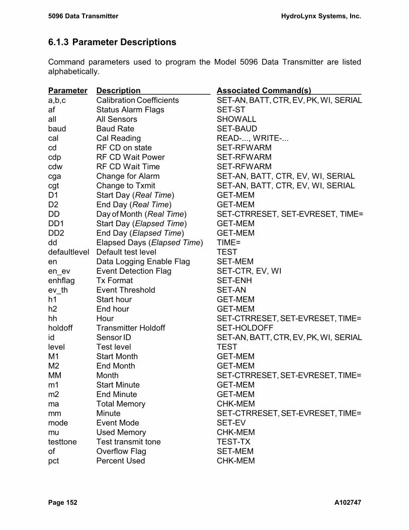
5096 Data Transmitter HydroLynx Systems, Inc.
Page 152 A102747
6.1.3 Parameter Descriptions
Command parameters used to program the Model 5096 Data Transmitter are listedalphabetically.
Parameter Description Associated Command(s) a,b,c Calibration Coefficients SET-AN, BATT, CTR, EV, PK, WI, SERIALaf Status Alarm Flags SET-STall All Sensors SHOWALLbaud Baud Rate SET-BAUDcal Cal Reading READ-..., WRITE-...cd RF CD on state SET-RFWARMcdp RF CD Wait Power SET-RFWARMcdw RF CD Wait Time SET-RFWARMcga Change for Alarm SET-AN, BATT, CTR, EV, WI, SERIALcgt Change to Txmit SET-AN, BATT, CTR, EV, WI, SERIALD1 Start Day (Real Time) GET-MEMD2 End Day (Real Time) GET-MEMDD Day of Month (Real Time) SET-CTRRESET, SET-EVRESET, TIME=DD1 Start Day (Elapsed Time) GET-MEMDD2 End Day (Elapsed Time) GET-MEMdd Elapsed Days (Elapsed Time) TIME=defaultlevel Default test level TESTen Data Logging Enable Flag SET-MEMen_ev Event Detection Flag SET-CTR, EV, WIenhflag Tx Format SET-ENHev_th Event Threshold SET-ANh1 Start hour GET-MEMh2 End hour GET-MEMhh Hour SET-CTRRESET, SET-EVRESET, TIME=holdoff Transmitter Holdoff SET-HOLDOFFid Sensor ID SET-AN, BATT, CTR, EV, PK, WI, SERIALlevel Test level TESTM1 Start Month GET-MEMM2 End Month GET-MEMMM Month SET-CTRRESET, SET-EVRESET, TIME=m1 Start Minute GET-MEMm2 End Minute GET-MEMma Total Memory CHK-MEMmm Minute SET-CTRRESET, SET-EVRESET, TIME=mode Event Mode SET-EVmu Used Memory CHK-MEMtesttone Test transmit tone TEST-TXof Overflow Flag SET-MEMpct Percent Used CHK-MEM

HydroLynx Systems, Inc. 5096 Data Transmitter
A102747 Page 153
Parameter Description Associated Command(s) pdc Pre-Divide Counter SET-CTR, WIpn Package Part Number RESETpre RF Preamble Time SET-RFWARMpwron RF Power On Time SET-RFWARMR Radio Type RESETraw Raw Reading READ-..., WRITE-...rcnt Reset Count RESETCNTrstate Reset Initialize State RESETINITs_int Sample Interval SET-AN, BATT, PK, ST, SERIALsn Sensor Number SET-..., READ-..., WRITE-...spt Seconds Per Tick SET-SPTss Second SET-CTRRESET, SET-EVRESET, TIME=staid Station ID READ-IDSW, SET-...string Search String HELPtf Status Change Flags SET-STtmode Time Mode Flag TIME-MODEtxrf RF Tx Warm Time SET-RFWARMt_int Transmit Interval SET-AN, BATT, CTR, EV, WI, SERIALtx_int Transmit Interval (PEAK WIND) SET-PKtx0 Transmit Zero Status SET-STval Value to Set WRITE-CTR, EV, SERIALver Firmware Version Number RESETvga Value for Alarm SET-PKvgt Value to Transmit SET-PKwa Analog Warm Time SET-WARMwcal Wind Run Cal Reading READ-WIwdir Wind Direction Reading READ-WIwe Wind Enable Flag SET-CTR, WIwind Combined Wind Reading READ-WIYYY1 Start Year GET-MEMYYY2 End Year GET-MEMYYYY Year SET-CTRRESET, SET-EVRESET, TIME=
5096 Data Transmitter HydroLynx Systems, Inc.
Page 154 A102747
6.2 Drawings
The following drawings are enclosed to assist in the installation, set up, andtrouble-shooting of problems.
AC107897 5096-81 Diagram shows the 7 input 5096 Data Transmitter assembly.
AC104045 5096 Wire Diagram shows the wiring between the 9601 board and theinterconnection board, sensor connectors, radio, solar panel and battery.
AC107911 Wiring Diagram, Typical Sensors to 5096N shows the sensor connectionpoints for the 5096N.
AC107908 T9601 PCB Assembly Diagram shows the components on the 9601 board.
AC104974 Interconnect PCB All Season Power to Pin B shows the trace to cut andjumper to solder on the Interconnect Board B104010-1 to select +12V powerfor the All Season Precipitation Gage.
AC104020 Console RS232 Cable, 9 Pin to 9 Pin shows the 5071C-5096 cable pin-outs.
AC104180 Outline, Pin Outs for Interconnect Circuit Board shows the 5096 DataTransmitter top cover connector pin outs for standard ALERT sensors, solarpanels, antennas, and RS232 console cable bulkhead connector.
A104973 Maintenance Report is used for recording general site and transmitterinformation and information taken during the recommended service checks.
A101229-2 Sensor Set Up Checklist is a worksheet used when setting up the 5096 DataTransmitter before installation. Keep a copy of the checklist with the unit.
A101018-4 Test Results Report is used for writing down information while testing the5096 Data Transmitter. Use it with tests outlined in Section 5.
AC107484 Transmission Formats shows the ALERT transmission formats. It is usefulin decoding reports received from a 5096 Data Transmitter through a radioreceiver and decoder.


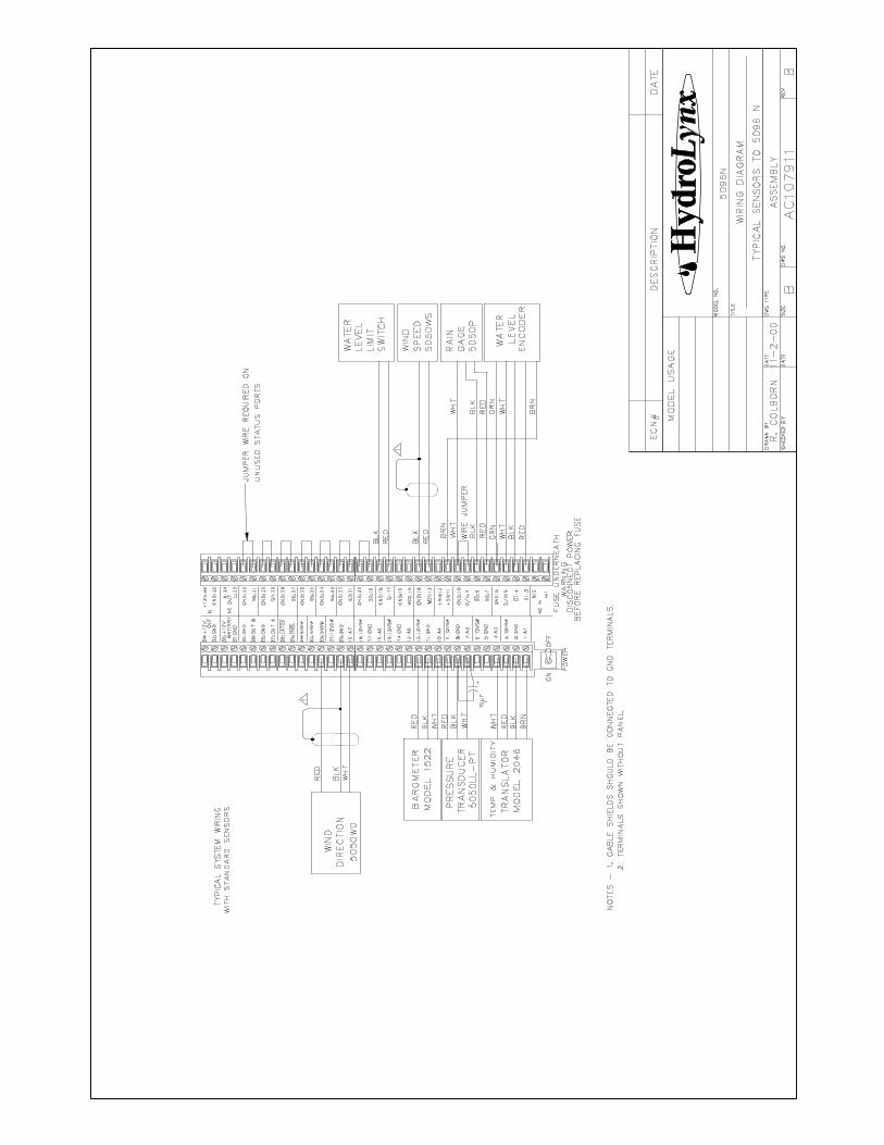


HydroLynx Systems, Inc. ! 950 Riverside Pkwy., Suite 10 ! West Sacramento, CA 95605Phone 916-374-1800 ! Fax 916-374-1877 ! Email [email protected]
Maintenance Report Document No. A104973
SITE INFORMATION
Location: Gauge type: ID#:
Purpose/Comments:
Weather conditions:
EQUIPMENT INFORMATION
Equipment Model # Asset # Comments
Data transmitter
Antenna
Battery
Solar panel
Sensors
TEST DATA
POWER
Battery voltage w/o load: Vdc w/ load: Vdc Difference: Vdc
Current Standby: :A w/ load: A
Solar panel w/o load: Vdc w/ load: A Reverse: mA
SIGNAL OUT - TX
Power out: W Reverse power: W Freq error: Hz Dev: ± kHz
SIGNAL IN - SENSOR
Sensor Measured Reading Comments
COMMENTS

HydroLynx Systems, Inc. ! 950 Riverside Pkwy., Suite 10 ! West Sacramento, CA 95605Phone 916-374-1800 ! Fax 916-374-1877 ! Email [email protected]
5096/5096N Sensor Set Up Checklist Document Number A101229-2Station ID: Station serial #: EPROM Version #:
Location: By: Date:
ANALOG Sensors Cal = (Raw * a) / b + cCommand sn ev_th t_int s_int cgt cga a b c id
SET-AN 1
SET-AN 2
SET-AN 3
SET-AN 4
SET-AN 5
SET-AN 6
SET-AN 7
SET-BATT $ $ $ $ $
EVENT SensorsCommand sn en_ev mode t_int cgt cga a b c id
SET-EV 1
SET-EV 2
WIND/COUNTER SensorsCommand sn en_ev pdc t_int cgt cga a b c we id
SET-WI 1
SET-CTR 2
STATUS SensorCommand sn tx0 t_int s_int tf af id
SET-ST $
PEAK WIND SensorsCommand sn s_int tx_int vgt vga a b c id
SET-PK 1
SET-PK 2
Notes:

HydroLynx Systems, Inc. ! 950 Riverside Pkwy., Suite 10 ! West Sacramento, CA 95605Phone 916-374-1800 ! Fax 916-374-1877 ! Email [email protected]
5096/5096N TEST RESULTS REPORT Document Number A101018-5
Date: Chassis serial number:
Inspector: PCB serial number:
Job number: EPROM version number:
Transmitter frequency: MHz Transmitter serial number:
Transmitter deviation: ± kHz Transmitter manufacturer:
PCB CHECK BY: DATE:
Vcc: Vdc Test switch: G Reset switch: G Analog on/off test: G
Stand-by current: :A ROM: G RAM: G ID switches: G Analog: G
Back-up batt: G Battery test: G Transmit power: G Digital: G
Init: G Clock: G LED test: G Status: G
UNIT TESTS BY: DATE:
Battery jumper: G 3-pin connector check: G Set UID:
A-1: A-2: A-3: A-4: A-5: A-6: A-7: BATT:
EV-1: EV-2: WD-1: WD-2: S1...S8:
RADIO TESTS BY: DATE:
Frequency error: Hz Deviation: ± kHz Power output: W
Self-report test: G Burn-in: G
RF warm: ENH Tx:
VISUAL INSPECTION BY: DATE:
Serial number tag? G Connections? G Dust covers? G
Silkscreen? G Solder joints? G Strain reliefs? G
Screws & lockwashers tight? G Wiring? G Lid closes? G
Neatness/completeness? G Bulkhead connectors? G Fuse (ac only)? G
Notes:


HydroLynx Systems, Inc. 5096 Data Transmitter
A102747 Page 167
6.3 5096 Firmware Enhancements
The following documents list the enhancements made to the 5096 firmware versions.
A101100 5096 Firmware Enhancements Version 3.0
A101101 5096 Firmware Enhancements Version 3.1
A101102 5096 Firmware Enhancements Version 3.2
A101103 5096 Firmware Enhancements Version 3.3
A101104 5096 Firmware Enhancements Version 4.0
A101105 5096 Firmware Enhancements Version 3.4
A101106 5096 Firmware Enhancements Version 3.5
A101107 5096 Firmware Enhancements Version 3.6
A101108 5096 Firmware Enhancements Version 3.7
A100740 5096 Firmware Enhancements Version 3.8
A100741 5096 Firmware Enhancements Version 3.9
A100742 5096 Firmware Enhancements Version 4.1
A100743 5096 Firmware Enhancements Version 4.2
A100744 5096 Firmware Enhancements Version 4.3
A100745 5096 Firmware Enhancements Version 4.4

HydroLynx Systems, Inc. ! 950 Riverside Pkwy., Suite 10 ! West Sacramento, CA 95605-1501Phone 916-374-1800 ! Fax 916-374-1877 ! Email [email protected]
5096 FIRMWARE ENHANCEMENTSDocument Number A101100
Page 1 of 1
Version No.: 3.0
Effective Date: January 5, 1994
Description of Changes:
1. Firmware copyright changed to NovaLynx Systems Inc.
2. Default parameters changed:
Rfwarm: 200, 100
Enhanced transmit mode: Off
3. Both RFwarm parameters displayed for SET-RFWARM command.
4. Status sensor transmission shows correct value.
5. Peak wind sample interval is displayed correctly.Peak wind computation and transmission works.
6. Memory logging will continue when old data overwriting enabled.
7. No sensor ID numbers are excluded from transmitting.

HydroLynx Systems, Inc. ! 950 Riverside Pkwy., Suite 10 ! West Sacramento, CA 95605-1501Phone 916-374-1800 ! Fax 916-374-1877 ! Email [email protected]
5096 FIRMWARE ENHANCEMENTSDocument Number A101101
Page 1 of 1
Version No.: 3.1
Effective Date: May 6, 1994
Description of Changes:
1. 5096-54,88,90,81,N versions available with Plug and Play parameter sets.

HydroLynx Systems, Inc. ! 950 Riverside Pkwy., Suite 10 ! West Sacramento, CA 95605-1501Phone 916-374-1800 ! Fax 916-374-1877 ! Email [email protected]
5096 FIRMWARE ENHANCEMENTSDocument Number A101102
Page 1 of 1
Version No.: 3.2
Effective Date: August 19, 1994
Description of Changes:
1. Pressing the RESET button twice quickly will initialize parameters with the station ID set inthe switches. This feature can be disabled or enabled.
2. Added new commands TEST and RESET that mimic the TEST and RESET button functions.
3. Added a new command SHOWALL to display all active sensor parameter sets, current rawand calibrated readings and all station setup parameters.
4. Resets are counted and can be displayed as a maintenance check. The reset count is reset oninits or by command.
5. Resets no longer align (restart) sample and transmit timers.
6. The TEST-TX command transmits for 5 seconds. A command parameter can be used to doa test transmission without tone for a frequency check. The TEST-TX command is nowsubject to the transmit hold-off timer.
7. Sample intervals on event and wind(counter) sensors were changed to transmit intervals.Reports are transmitted on transmit intervals without having to satisfy a change requirement.Event transmissions are still subject to the change requirement.
8. Added a transmit interval to the status sensor.
9. Sample readings are no longer logged to memory unless they meet the change requirementfor transmission.
10. Analog sensor calibrated readings can no longer go negative, they are limited to 0.
11. The transmit 0 parameter for analog sensors was changed to an event threshold. The sensorreading must be greater or equal to this threshold before an event change report istransmitted. This allows a narrow change to transmit to be set on PTs to track water levelrises but eliminates useless reports from a dry PT due to temperature fluctuations.
12. Sensor ID setup no longer is effected by default sensor ID numbers assigned to inactivesensors.
13. The HELP command now shows the command list alphabetically.
14. The parameter displays are now organized into columns for easy reading.

HydroLynx Systems, Inc. ! 950 Riverside Pkwy., Suite 10 ! West Sacramento, CA 95605-1501Phone 916-374-1800 ! Fax 916-374-1877 ! Email [email protected]
5096 FIRMWARE ENHANCEMENTSDocument Number A101103
Page 1 of 1
Version No.: 3.3
Effective Date: June 30, 1995
Description of Changes:
1. Holding down the TEST button and then resetting the 5096 by pressing the RESET buttonor by powering off and then on executes a parameter reset. This replaces the double RESETfeature in version 3.2. The double reset feature caused problems on some transmitters whosepower up voltage fluctuated and creating multiple resets thus inadvertently causing aparameter reset.
2. EVENT and COUNTER sensor accumulators can be reset to 0 at a programmed day of year.A report is transmitted when the accumulator is reset.
3. A "listen before talk" feature was added to the 5096 firmware. The 5096 can test for radiocarrier detection before transmitting. This helps prevent radio "collisions" that would occurif two or more 5096 units transmitted at the same time. This feature requires a boardmodification and only works with the certain radios (consult factory).
4. The 5096 and certain radios have hardware timers that shutdown the radio if it is left on toolong. This is done to prevent the radio from overheating. It also prevents a radio from gettingstuck on and interfering with all other transmitters near it. To avoid the radio hardwareshutdown the 5096 firmware turns the radio power on to test for carrier and then turns offpower while it is waiting for its next test (100 milliseconds).
5. Special version 3.3R added to support the Ritron synthesized frequency radio. This radiorequires an 800 millisecond warm-up for frequency lock before transmitting.
Note: Do not use the carrier detect feature in version 3.3 with the Ritron radio. The radiohardware timer will shutdown the radio before a lack of carrier is detected after the 5096 firstdetects a carrier.
6. Firmware versions:3.3 - Use with crystal radios.3.3R - Use with synthesized frequency radios.

HydroLynx Systems, Inc. ! 950 Riverside Pkwy., Suite 10 ! West Sacramento, CA 95605-1501Phone 916-374-1800 ! Fax 916-374-1877 ! Email [email protected]
5096 FIRMWARE ENHANCEMENTSDocument Number A101104
Page 1 of 1
Version No.: 3.4
Effective Date: October 1, 1996
Description of Changes:
1. The Enhanced IFLOWS transmission format was added to the radio data formats.Transmission formats are now defined as Standard ALERT, Enhanced ALERT, andEnhanced IFLOWS. Firmware version type 3.4RI has the Enhanced IFLOWS transmissionformat selected by default. Other firmware version types, 3.4 and 3.4R, have the StandardALERT format selected by default.
2. Two new parameters were added to the SET-RFWARM command to control the "listenbefore talk" radio power and to allow programming of the radio power on wait time.
The radio power is turned off by default for crystal radios (version 3.4) while waiting for noradio carrier. The radio is turned on and allowed to warm-up before testing for carrier again.Since synthesized radios have such a long warm-up timer (800 milliseconds), the radio poweris not turned off by default (version 3.4R) while waiting for no radio carrier. Override thecarrier detect wait power state with the cdp parameter in the SET-RFWARM command.
The radio power on wait time for crystal radios is 25 milliseconds by default (version 3.4).It is 800 milliseconds for synthesized frequency radios by default (version 3.4R). Override thepower on wait time default with the pwron parameter in the SET-RFWARM command.
3. Eliminated repeat transmission of 2 wire rain gage reports after the hold-off timer. Thisprogram fix also eliminated repeat transmission of 5050P rain gages that would occuroccasionally.
4. The test transmission time on (with tone and no tone) is adjusted to match the radio poweron time to prevent radio shutdown by the hardware timer because of longer power on waittimes required by synthesized frequency radios.
Firmware versions:3.4 - Use with crystal radios.3.4R - Use with synthesized frequency radios.3.4I - Use Enhanced IFLOWS format with crystal radios.3.4RI - Use Enhanced IFLOWS format with synthesized frequency radios.
Firmware upgrade costs:$100.00 for the firmware upgrade license.The upgraded firmware is provided on one EPROM chip.Duplication by copying the EPROM is authorized within the same agency orcompany.Additional firmware upgrades on EPROM chips can be ordered at $50.00 each.Firmware costs do not include tax or shipping.

HydroLynx Systems, Inc. ! 950 Riverside Pkwy., Suite 10 ! West Sacramento, CA 95605-1501Phone 916-374-1800 ! Fax 916-374-1877 ! Email [email protected]
5096 FIRMWARE ENHANCEMENTSDocument Number A101105
Page 1 of 1
Version No.: 4.0
Effective Date: October 1, 1996
Description of Changes:
1. The 5096 console port communications now use half duplex mode.
2. Serial sensor support has been added to version type 4.0A. The first serial sensor supportedis the absolute encoder. A sample interval parameter, s_int, was added to the SET-EVcommand. Serial port switch control was added to switch the 5096 RS232 port between theconsole and the absolute encoder.
Firmware versions:4.0 - Use with crystal radios.4.0R - Use with synthesized frequency radios.4.0I - Use Enhanced IFLOWS format with crystal radios.4.0RI - Use Enhanced IFLOWS format with synthesized frequency radios.4.0A - Absolute encoder with crystal radios.4.0AR - Absolute encoder with synthesized frequency radios.4.0AI - Absolute encoder, Enhanced IFLOWS format with crystal radios.4.0ARI - Absolute encoder, Enhanced IFLOWS format with synthesized
frequency radios.
Firmware upgrade costs:$100.00 for the firmware upgrade license.The upgraded firmware is provided on one EPROM chip.Duplication by copying the EPROM is authorized within the same agency orcompany.
Additional firmware upgrades on EPROM chips can be ordered at $50.00 each.
Firmware costs do not include tax or shipping.

HydroLynx Systems, Inc. ! 950 Riverside Pkwy., Suite 10 ! West Sacramento, CA 95605-1501Phone 916-374-1800 ! Fax 916-374-1877 ! Email [email protected]
5096 FIRMWARE ENHANCEMENTSDocument Number A101106
Page 1 of 1
Version No.: 3.5
Effective Date: June 6, 1997
Description of Changes:
1. Log memory and showall displays would hang at 9600 baud. The serial output task had amemory request imbedded in its FIFO request. A standoff would occur between the serialoutput task and the command task when memory was loaded with many lines of output. Thememory request was taken out from within the FIFO request to solve this problem.
2. CTRL-C did not terminate serial output for showall and did not work reliably for get-memcommands. Now CTRL-C terminates output for all commands.
Firmware upgrade costs:$100.00 for the firmware upgrade license.The upgraded firmware is provided on one EPROM chip.Duplication by copying the EPROM is authorized within the same agency orcompany.
Additional firmware upgrades on EPROM chips can be ordered at $50.00 each.
Firmware costs do not include tax or shipping.

HydroLynx Systems, Inc. ! 950 Riverside Pkwy., Suite 10 ! West Sacramento, CA 95605-1501Phone 916-374-1800 ! Fax 916-374-1877 ! Email [email protected]
5096 FIRMWARE ENHANCEMENTSDocument Number A101107
Page 1 of 1
Version No.: 3.6
Effective Date: December 7, 1999
Description of Changes:
1. A 5096-S version of the firmware was added to support serial sensors and dial-in modems.New commands were added to program serial sensors for wireless sensor links: read-serial,set_serial, write-serial. Serial sensors take over an analog sensor number when at least oneparameter is set by the set-serial #,... command, where # is the analog sensor number. Use theset-an #,... command programming at least one parameter to restore the sensor to the analognumber. The default console baud rate was set to 9600 baud.
2. A new command, READ-IDSW, was added to read and display ID switches.
3. An ‘M’ radio version for the firmware was added to support Maxon radio parameters: 100msradio power on delay and radio power is on while waiting for carrier detect to drop.
4. The transmitter tone and battery voltage test was fixed for radios with longer power on times.The test now waits the radio power on delay after turning on the radio power and beforekeying the radio. The battery voltage is read under load after the transmitter tone test.
5. The 5096-90 version now allows programming of Analog sensor 5.
6. The allowed radio preamble time was increased from 100ms to 2000ms.

HydroLynx Systems, Inc. ! 950 Riverside Pkwy., Suite 10 ! West Sacramento, CA 95605-1501Phone 916-374-1800 ! Fax 916-374-1877 ! Email [email protected]
5096 FIRMWARE ENHANCEMENTSDocument Number A101108
Page 1 of 1
Version No.: 3.7
Effective Date: February 23, 2000
Description of Changes:
1. Added a delay at startup to let power supply come up before starting program. This preventsreset looping at power up caused by reading ID switches before power supply voltage is upto operational level.
2. Fixed version 3.6 error in CHK-MEM command display of percent of logging memory used.
3. Fixed version 3.6 error in READ-CTR command displayof COUNTER parameters as WINDparameters when the wind enable flag was not set.

HydroLynx Systems, Inc. ! 950 Riverside Pkwy., Suite 10 ! West Sacramento, CA 95605-1501Phone 916-374-1800 ! Fax 916-374-1877 ! Email [email protected]
5096 FIRMWARE ENHANCEMENTSDocument Number A100740
Page 1 of 1
Version No.: 3.8
Effective Date: September 14, 2000
Description of Changes:
1. Divided the 5096 test into two levels. Test level one transmits all active sensors. Test leveltwo transmits all active sensors and extends the tone signal for 5 seconds. Then it tests theROM, RAM, battery and clock. Finally it transmits without tone for 5 seconds.
2. Added command arguments to the test command. The first argument sets the test level: 1 or2. The second argument sets the default test level: 1 or 2. If no arguments are used the defaulttest level is performed.
3. The TEST switch performs the default test level set by the TEST command.
4. The SHOWALL command displays the default test level.
HydroLynx Systems, Inc. ! 950 Riverside Pkwy., Suite 10 ! West Sacramento, CA 95605-1501Phone 916-374-1800 ! Fax 916-374-1877 ! Email [email protected]
5096 FIRMWARE ENHANCEMENTSDocument Number A100741
Page 1 of 1
Version No.: 3.9.02
Effective Date: January 31, 2005
Description of Changes:
Initial Release: February 7, 2001
1. Fixed a problem that corrupted the data logging memory after a power down reset.
2. Added version 82 that has a 3 second analog warm default.
Updated Release: January 31, 2005
3. Fixed the error that caused a time offset in the logged rainfall data after an automatic counterreset to zero.
4. When GET-MEM reads an event data report, it adjusts the following timed data reports tokeep the data report time in sync.
5. When GET-MEM reads an invalid logged data report, it skips the report and then continueswith the logged data report display.

HydroLynx Systems, Inc. ! 950 Riverside Pkwy., Suite 10 ! West Sacramento, CA 95605-1501Phone 916-374-1800 ! Fax 916-374-1877 ! Email [email protected]
5096 FIRMWARE ENHANCEMENTSDocument Number A100742
Page 1 of 1
Version No.: 4.1
Effective Date: May 20, 2004
Description of Changes:
1. Fixed peak wind computational error that caused erroneous large peak wind values.
2. Fixed time update and event processing during long logged memory dumps.
3. Pausing the logged data, help or showall displays no longer causes serial output buffer errors.
4. Time and event interrupts are now processed in the middle of a logged data display.
5. Morse code logic has never been used and so was removed.
6. Added command arguments to set-rfwarm to define the carrier detect on state.
7. Transmissions are no longer held until the next clock tick when the transmit holdoff timer isset to zero.
8. Fixed analog warm time drift for longer warm times (greater than 100 milliseconds).
9. Test transmission no longer transmit before a long sensor warm time is done.
10. Limit analog warm wait to 10msec for status, battery voltage, and wind direction sensorreads. Long analog warm times no longer effect these sensors. This eliminates the event windtransmission delay caused by long warm times when reading the wind direction.
11. The battery test was changed to power up the radio to put the battery under load then powerdown the radio before reading the battery voltage. This eliminated bad battery voltage readscaused by noise from power amps.
12. Eliminated pause in the middle of a line of serial output when a transmission occurs.
13. Fixed wind/counter display type for read-wi/read-ctr.
14. Added 5096-82 version the has a default 3 second analog warm time.
15. Changed Maxon RF Power on default to 400 milliseconds to correct key drop out when radiois cold.
16. An NB package has been added that is like the N package except that the battery sensor isenabled with an ID offset of 8 and transmit interval of 24 hours.
17. Display copyright year on program start.

HydroLynx Systems, Inc. ! 950 Riverside Pkwy., Suite 10 ! West Sacramento, CA 95605-1501Phone 916-374-1800 ! Fax 916-374-1877 ! Email [email protected]
5096 FIRMWARE ENHANCEMENTSDocument Number A100743
Page 1 of 1
Version No.: 4.2
Effective Date: September 10, 2004
Description of Changes:
1. Set default mode for EV-2 to mode 6 for all packages. Mode 6 uses a 200ms timer to ignorethe second pulse generated by 5050P-MS momentary pulse rain gauges. This eliminates theneed to set the event mode to 2. If a high speed counter is used on EV-2, reset the mode to4 to disable the 200ms timer logic.
2. The 81 package now uses a 3 second analog warm time by default. The 82 package has beenretired.
3. A new package NB was added that is similar to the N package with the battery sensor defaulttransmit interval set to 1 day, sample interval set to 3 hours with a change to generate atransmission set to 50 (0.50 volts).
4. Fixed the error that caused a time offset in the logged rainfall data after an automatic counterreset to zero.
5. Wind sensor timed transmission are not done until the wind direction sensor reading isfinished.

HydroLynx Systems, Inc. ! 950 Riverside Pkwy., Suite 10 ! West Sacramento, CA 95605-1501Phone 916-374-1800 ! Fax 916-374-1877 ! Email [email protected]
5096 FIRMWARE ENHANCEMENTS
Document Number A100744Page 1 of 1
Version No.: 4.3.2
Effective Date: June 30, 2005
Description of Changes:
Initial Release: February 23, 2005
1. The status sensor will now transmit and log one report on the test interval when it returns toa zero state. In previous versions, the status sensor would only transmit on the test intervalwhen the status value was not zero.
2. If no time parameters are specified for a GET-MEM command then a logged data report’sdate and time are not checked before printing it. This allow the printing of all logged datareports even if they are out of time order.
3. When GET-MEM reads an event data report, it adjusts the following timed data reports tokeep the data report time in sync. Timed data logging starts with an event report to record thetime of the first report. When data logging is stopped and restarted, new start times arerecorded.
4. When GET-MEM reads an invalid logged data report, it skips the report and then continueswith the logged data report display.
5. When the wind direction sensor is calibrated, the calibrated direction is used in the windreport format.
6. A new option was added to the TEST-TX command to transmit a single high or low tone.TEST-TX 0 transmits both high and low tonesTEST-TX 1 transmits no tonesTEST-TX 2 transmits the high toneTEST-TX 3 transmits the low tone
7. Allow use of READ-AN and SET-AN for battery sensor for all packages. This allowscalibration programming of the battery sensor if desired.
8. The transmit hold off timer is reset when the SET_HOLDOFF command is executed.
Updated Release: 4.3.1 April 11, 2005
9. Limit calibrated wind direction sensor value in the wind report format to range 0 to 63.
Updated Release: 4.3.2 June 30, 2005
10. Fixed error in computing radio power on and key on wait timers longer than 100ms.

HydroLynx Systems, Inc. ! 950 Riverside Pkwy., Suite 10 ! West Sacramento, CA 95605-1501Phone 916-374-1800 ! Fax 916-374-1877 ! Email [email protected]
5096 FIRMWARE ENHANCEMENTS
Document Number A100745Page 1 of 1
Version No.: 4.4.1
Effective Date: January 30, 2006
Description of Changes:
Initial Release: September 19, 2005
1. Fixed display of logged memory date and time broken in version 4.3.
2. Allow time samples during display of logged memory.
3. Timed and event report printing do not interrupt command printing.
4. Fixed decimal display of logged memory used.
5. Align timers and change in time no longer close logging memory tables. The next report islogged as an event report which re-aligns the time.
Updated Release: 4.4.1 January 30, 2006
6. Increased rain gauge momentary pulse delay from 200 to 450 milliseconds to support the AllWeather Rain Gauge.