5116 - pr electronics series/5116/manual...pr electronics a/s tilbyder et bredt program af analoge...
TRANSCRIPT

5 1 1 6
P r o g r a m m a b l eT r a n s m i t t e r
N o . 5 1 1 6 V 1 0 3 - U KF r o m s e r . n o . 0 6 0 0 6 9 0 0 1
1651
PR electronics A/S tilbyder et bredt program af analoge og digitale signalbehandlingsmoduler til industriel automation. Programmet består af Isolatorer, Displays, Ex-barrierer, Temperaturtransmittere, Universaltransmittere mfl. Vi har modulerne, du kan stole på i selv barske miljøer med elektrisk støj, vibrationer og temperaturudsving, og alle produkter opfylder de strengeste internationale standarder. Vores motto »Signals the Best« er indbegrebet af denne filosofi – og din garanti for kvalitet.
PR electronics A/S offers a wide range of analogue and digital signal conditioning devices for industrial automation. The product range includes Isolators, Displays, Ex Interfaces, Temperature Transmitters, and Universal Devices. You can trust our products in the most extreme environments with electrical noise, vibrations and temperature fluctuations, and all products comply with the most exacting international standards. »Signals the Best« is the epitome of our philosophy – and your guarantee for quality.
PR electronics A/S offre une large gamme de produits pour le traite ment des signaux analogiques et numériques dans tous les domaines industriels. La gamme de produits s’étend des transmetteurs de température aux afficheurs, des isolateurs aux interfaces SI, jusqu’aux modules universels. Vous pouvez compter sur nos produits même dans les conditions d’utilisation sévères, p.ex. bruit électrique, vibrations et fluctuations de température. Tous nos produits sont conformes aux normes internationales les plus strictes. Notre devise »SIGNALS the BEST« c’est notre ligne de conduite - et pour vous l’assurance de la meilleure qualité.
PR electronics A/S verfügt über ein breites Produktprogramm an analogen und digitalen Signalverarbeitungsgeräte für die in-dustrielle Automatisierung. Dieses Programm umfasst Displays, Temperaturtransmitter, Ex- und galvanische Signaltrenner, und Universalgeräte. Sie können unsere Geräte auch unter extremen Einsatzbedingungen wie elektrisches Rauschen, Erschütterungen und Temperaturschwingungen vertrauen, und alle Produkte von PR electronics werden in Überein stimmung mit den strengsten internationalen Normen produziert. »Signals the Best« ist Ihre Garantie für Qualität!
DK
UK
FR
DE

5116V103-UK 1
PROGRAMMABLE TRANSMITTER
5116
CONTENTS
Warning ....................................................................................................... 2Safety instructions ................................................................................. 3Instructions for intrinsically safe installation of 5116B ........ 4How to demount system 5000 ........................................................ 5Application ................................................................................................. 6Technical characteristics ...................................................................... 6Mounting / installation ......................................................................... 6Applications............................................................................................... 7Order: 5116 ............................................................................................... 8Electrical specifications........................................................................ 8Connections .............................................................................................. 14Connections .............................................................................................. 15Block diagram ........................................................................................... 16Graphic depiction of relay actions Increasing / Decreasing .. 17Graphic depiction of relay action Window .................................... 175116 connection to Loop Link .......................................................... 18Activation of the process calibration button ............................... 18Configuration of relay 1 & 2 in PReset .......................................... 19Process calibration 0% and 100% or only 0% ............................ 20Error functions ......................................................................................... 21Appendix .................................................................................................... 22 FM Control drawing No. 5116QF01 ......................................... 22

2 5116V103-UK
WARNINGThis device is designed for connection to hazardous electric voltages. Ignoring this warning can result in severe personal injury or mechanical damage. To avoid the risk of electric shock and fire, the safety instructions of this manual must be observed and the guidelines fol lowed. The specifications must not be exceeded, and the device must only be applied as described in the following. Prior to the commissioning of the device, this manual must be examined carefully. Only qualified personnel (technicians) should install this device. If the equipment is used in a manner not specified by the manufacturer, the protection provided by the equipment may be impaired.
WARNINGUntil the device is fixed, do not connect hazardous voltages to the device. The following operations should only be carried out on a disconnected device and under ESD safe conditions: General mounting, connection and disconnection of wires. Troubleshooting the device.
Repair of the device and replacement of circuit breakers must be done by PR electronics A/S only.
WARNINGTo keep the safety distances, the relay contacts on the device must not be connected to both hazardous and non-hazardous volt ages at the same time. SYSTEM 5000 must be mounted on a DIN rail according to DIN 46277. The communication connector of SYSTEM 5000 is connected to the input terminals on which dangerous voltages can occur, and it must only be connected to the programming unit Loop Link by way of the enclosed cable.
GENERAL
HAZARD - OUS
VOLTAGE
INSTAL-LATION

5116V103-UK 3
SYMBOL IDENTIFICATION
Triangle with an exclamation mark: Warning / demand. Potentially lethal situations.
The CE mark proves the compliance of the device with the essential requirements of the directives.
The double insulation symbol shows that the device is protected by double or reinforced insulation.
Ex devices have been approved for use in connection with installations in explosive areas.
SAFETY INSTRUCTIONS
DEFINITIONSHazardous voltages have been defined as the ranges: 75 to 1500 Volt DC, and 50 to 1000 Volt AC. Technicians are qualified persons educated or trained to mount, operate, and also troubleshoot technically correct and in accordance with safety regulations. Operators, being familiar with the contents of this manual, adjust and operate the knobs or potentiometers during normal operation.
RECEIPT AND UNPACKINGUnpack the device without damaging it. The packing should always follow the device until this has been permanently mounted. Check at the receipt of the device whether the type corresponds to the one ordered.
ENVIRONMENTAvoid direct sunlight, dust, high temperatures, mechanical vibrations and shock, as well as rain and heavy moisture. If necessary, heating in excess of the stated limits for ambient temperatures should be avoided by way of ventilation. All devices fall under Installation Category II, Pollution Degree 1, and Insulation Class II.

4 5116V103-UK
MOUNTINGOnly technicians who are familiar with the technical terms, warnings, and instructions in the manual and who are able to follow these should connect the device. Should there be any doubt as to the correct handling of the device, please contact your local distributor or, alternatively,
PR electronics A/S www.prelectronics.com
Mounting and connection of the device should comply with national legislation for mounting of electric materials, i.e. wire cross section, protective fuse, and location. Descriptions of input / output and supply connections are shown in the block diagram and side label.The following apply to fixed hazardous voltages-connected devices:
The max. size of the protective fuse is 10 A and, together with a power switch, it should be easily accessible and close to the device. The power switch should be marked with a label telling it will switch off the volt age to the device.
Year of manufacture can be taken from the first two digits in the serial number.
INSTRUCTIONS FOR INTRINSICALLY SAFE INSTALLATION OF 5116BThe intrinsically safe circuits are galvanically connected to the communications interface unit.
The communications interface may only be connected tempo rarily, under the condition that the connectors with terminal numbers 41...44 and 51...54 are disconnected on the 5116B.
When a higher ingress protection than IP20 is required, this has to be achieved by an additional enclosure which is suitable for the applicable environmental conditions.
When two or more units are placed next to each other it has to be assured that all the terminal numbers 41...44 and 51...54 are placed on the same side and are separated from the non-intrinsically safe circuits of the units which could be mounted above or below it.
Each combination of circuits (to terminations 41...44 or to terminations 51...53 or to terminations 51...54) shall be connected via separated cables or if the combinations are in one cable shall be type A or B in accordance with EN 60079-14 Clause 12.2.2.8.

5116V103-UK 5
CALIBRATION AND ADJUSTMENTDuring calibration and adjustment, the measuring and connection of external voltages must be carried out according to the specifications of this manual. The technician must use tools and instruments that are safe to use.
NORMAL OPERATIONOperators are only allowed to adjust and operate devices that are safely fixed in panels, etc., thus avoiding the danger of personal injury and damage. This means there is no electrical shock hazard, and the device is easily accessible.
CLEANINGWhen disconnected, the device may be cleaned with a cloth moistened with distilled water.
LIABILITYTo the extent that the instructions in this manual are not strictly observed, the customer cannot advance a demand against PR electronics A/S that would otherwise exist according to the concluded sales agreement.
HOW TO DEMOUNT SYSTEM 5000
First, remember to demount the connectors with hazardous voltages.
Picture 1: Detach the device from the DIN rail by lifting the bottom lock.

6 5116V103-UK
PROGRAMMABLE TRANSMITTER 5116
• Input for RTD, TC, mV, Ohm, potmeter, mA and V • 2-wire supply > 16.5 V • Bipolar voltage input • Output for current, voltage and 2 relays • Universal AC or DC supply
Application
• Linearised, electronic temperature measurement with RTD or TC sensor.
• Conversion of linear resistance variation to a standard analogue current / voltage signal, i.e. from solenoids and butterfly valves or linear movements with attached potentio meter.
• Power supply and signal isolator for 2-wire transmitters.
• Process control with 2 potential-free relay contacts which can be configured for advanced functions.
• Galvanic separation of analogue signals and measurement of floating signals.
Technical characteristics
• Within a few seconds the user can program PR5116 to suit the specific application.
• By way of the front push-button the input can be calibrated to the exact span of the process. Zero drift on the process signal can be adjusted by a single press of the front buttton.
• Continuous check of vital stored data for safety reasons.
• 3-port 3.75 kVAC galvanic isolation.
Mounting / installation
• Mounted vertically or horizontally on a DIN rail. As the devices can be mounted without any distance between neighbouring units, up to 42 devices can be mounted per metre.

33
32
31
14
13
12
11
24
23
22
21
mA
mA
V V
mA
44
43
42
41
54
53
52
51
4 3 2
+
-
+
-
+
-
+
-+
-
+
-
+
-
+
-+
-
5116V103-UK 7
APPLICATIONS
Input signals:
Current Voltage
Pote
ntio
met
er
RTD and lin. R
TCConnection, wires
V<= 2.5 V
2-wire transmitter
V> 2.5 V
Bi-polar mV
Supply:
21.6...253 VAC or
19.2...300 VDC
Output signals:Relays
Analogue, 0/4...20 mA and voltage
2-wire transmitter output

8 5116V103-UK
*NB! Please remember to order CJC connectors type 5910/5910Ex for TC inputs with internal CJC
Electrical specificationsEnvironmental conditionsSpecifications range ............................................... -20°C to +60°CCalibration temperature ........................................ 20...28°CRelative humidity..................................................... < 95% RH (non-cond.)Protection degree .................................................... IP20
Mechanical specificationsDimensions (HxBxD) ............................................... 109 x 23.5 x 130 mmWeight .......................................................................... 235 gMax. wire size ............................................................ 1 x 2.5 mm2 stranded wireMounting on DIN rail type .................................... DIN 46277Screw terminal torque ........................................... 0.5 NmVibration ...................................................................... IEC 60068-2-6 : 2007 2...13.2 Hz ............................................................. ±1 mm 13.2...100 Hz ........................................................ ±0.7 g
Common specificationsSupply voltage, universal ..................................... 21.6...253 VAC, 50...60 Hz or 19.2...300 VDCInternal consumption ............................................. ≤ 2 W Max. consumption .................................................... ≤ 3 W Fuse ............................................................................... 400 mA SB / 250 VAC Isolation voltage, test / operation .................... 3.75 kVAC / 250 VAC Communications interface ................................... Loop Link Signal / noise ratio .................................................. Min. 60 dB (0...100 kHz) Updating time: Temperature / ±mV input ................................ 115 ms mA / V / mV input ............................................... 75 ms
Type Version
5116 Standard. . . . . . . . . . . . . . : A ATEX Ex and FM. . . . . . . : B
Order: 5116

5116V103-UK 9
Response time (0...90%, 100...10%), programmable: Temperature / ± mV input ............................... 400 ms to 60 s mA / V / mV input ............................................... 250 ms to 60 s Signal dynamics, input ........................................... 22 bit Signal dynamics, output ....................................... 16 bit
Accuracy, the greater of the general and basic values:
Auxiliary supplies:Reference voltage ................................................... 2.5 VDC ±0.5% / 15 mA2-wire supply ( pin 54...52) ................................. 28...16.5 VDC / 0...20 mA
EMC immunity influence .................................................. < ±0.5% of span Extended EMC immunity: NAMUR NE 21, A criterion, burst ................................. < ±1% of span
General values
Input type
Absolute accuracy
Temperature coefficient
All ≤ ±0.05% of span ≤ ±0.01% of span / °C
Basic values
Input type
Basic accuracy
Temperature coefficient
mA ≤ ±4 µA ≤ ±0.4 µA / °C
Volt ≤ ±10 µV ≤ ±1 µV / °C
RTD ≤ ±0.2°C ≤ ±0.01°C / °C
Lin. resistance ≤ ±0.1 Ω ≤ ±10 mΩ / °C
TC type: E, J, K, L, N, T, U
≤ ±1°C
≤ ±0.05°C / °C
TC type: B, R, S, W3, W5, LR
≤ ±2°C
≤ ±0.2°C / °C
10 5116V103-UK
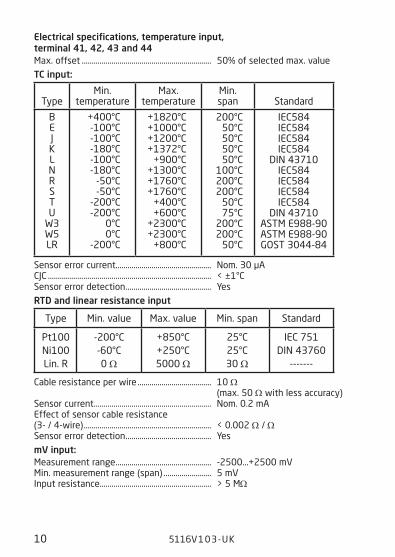
Electrical specifications, temperature input, terminal 41, 42, 43 and 44Max. offset ................................................................. 50% of selected max. value
TC input:
Sensor error current ................................................ Nom. 30 µA CJC .................................................................................. < ±1°C Sensor error detection ........................................... Yes
RTD and linear resistance input
Cable resistance per wire ..................................... 10 Ω (max. 50 Ω with less accuracy)Sensor current ........................................................... Nom. 0.2 mAEffect of sensor cable resistance(3- / 4-wire) ................................................................ < 0.002 Ω / ΩSensor error detection ........................................... Yes
mV input:Measurement range ................................................ -2500...+2500 mV Min. measurement range (span) ........................ 5 mV Input resistance........................................................ > 5 MΩ
Type Min. value Max. value Min. span Standard
Pt100 Ni100 Lin. R
-200°C -60°C 0 Ω
+850°C +250°C 5000 Ω
25°C 25°C 30 Ω
IEC 751 DIN 43760
-------
Type
Min. temperature
Max. temperature
Min. span
Standard
B E J K L N R S T U
W3 W5 LR
+400°C -100°C -100°C -180°C -100°C -180°C
-50°C -50°C
-200°C -200°C
0°C 0°C
-200°C
+1820°C +1000°C +1200°C +1372°C
+900°C +1300°C +1760°C +1760°C
+400°C +600°C
+2300°C +2300°C
+800°C
200°C 50°C 50°C 50°C 50°C
100°C 200°C 200°C
50°C 75°C
200°C 200°C
50°C
IEC584 IEC584 IEC584 IEC584
DIN 43710 IEC584 IEC584 IEC584 IEC584
DIN 43710 ASTM E988-90 ASTM E988-90 GOST 3044-84

5116V103-UK 11
Electrical specifications, mA / V input, terminal 51, 52, 53 and 54Max. offset ................................................................. 50% of selected max. value
Current input:Measurement range ................................................ 0...100 mA Min. measurement range (span) ........................ 4 mAInput resistance: Supplied unit ........................................................ Nom. 10 Ω + PTC 10 Ω Non-supplied unit ............................................... RSHUNT = ∞, VDROP < 6 V Sensor error detection: loop error on 4...20 mA signals ..................... Yes
Voltage inputMeasurement range ................................................ 0...250 VDC Min. measurement range (span) ........................ 5 mVDC Input resistance ≤ 2.5 VDC .............................. Nom. 10 MΩ > 2.5 VDC .............................. Nom. 5 MΩPotentiometer input via 2.5 V ref.Potentiometer min. ................................................ 170 ΩElectrical specifications - OUTPUTMax. offset ................................................................. 50% of selected max. value
Current outputSignal range ............................................................... 0...20 mAMin. signal range (span) ........................................ 10 mALoad (max.) ................................................................. 20 mA / 600 Ω / 12 VDCLoad stability ............................................................. ≤ 0.01% of span / 100 ΩCurrent limit ............................................................... ≤ 28 mA
Voltage outputSignal range ............................................................... 0...10 VDCMin. signal range (span) ........................................ 500 mVLoad (min.) .................................................................. 500 kΩ2-wire 4...20 mA outputSignal range ............................................................... 4...20 mALoad stability ............................................................. ≤ 0.01% of span / 100 ΩLoad resistance......................................................... ≤ (Vsupply-3.5) / 0.023 A [Ω]Max. external 2-wire supply ............................... 29 VDCEffect of external 2-wire supply voltage variation ...................................................... < 0.005% of span / V
Sensor error detection and loop error on 4...20 mAProgrammable ........................................................... 0...23 mANAMUR NE43 Upscale ........................................... 23 mANAMUR NE43 Downscale ..................................... 3.5 mA

12 5116V103-UK
Relay outputsMax. voltage .............................................................. 250 VRMS Max. current ............................................................... 2 A / AC Max. AC power .......................................................... 500 VA Max. current at 24 VDC ......................................... 1 A Sensor error detection ........................................... Break / Make / Hold / None
Ex / I.S. approval - 5116B
KEMA 04ATEX1316 X............................................ II (1) GD
[EEx ia] IICApplicable for zone ................................................. 0, 1, 2, 20, 21 or 22
Ex / I.S. data for 5116BUm .................................................................................. : 253 VUm, Loop Link ............................................................ : 60 V
Ex / I.S. data for temperature / bipolar mV inputTerminal 41, 42, 44 and 43 Uo ................................................................................... : 7.5 V Io ..................................................................................... : 2.2 mA Po .................................................................................... : 4.2 mW Co .................................................................................... : 6 μF Lo .................................................................................... : 1.0 H
Ex / I.S. data for unipolar mA / V input:Terminal 51, 52 and 53Uo ................................................................................... : 7.5 V Io ..................................................................................... : 2.2 mA Po .................................................................................... : 4.2 mW Co .................................................................................... : 6 μF Lo .................................................................................... : 1.0 H
Ex / I.S. data when using 2-wire supply / reference voltageTerminal 51, 52, 53 and 54Uo ................................................................................... : 28 V Io ..................................................................................... : 93 mA Po .................................................................................... : 650 mW
IIC IIB IIACo: 75 nF 645 nF 2 μF
Lo: 3 mH 16 mH 31 mH

5116V103-UK 13
ApprovalsEMC 2004/108/EC .................................................. EN 61326-1LVD 2006/95/EC ...................................................... EN 61010-1PELV/SELV .................................................................. IEC 364-4-41 and EN 60742UL, Standard for Safety ......................................... UL 61010-1EAC TR-CU 020/2011............................................. EN 61326-1
Marine approvalDet Norske Veritas, Ships & Offshore ............. Standard for Certification No. 2.4
I.S. / ExATEX 94/9/EC ............................................................ KEMA 04ATEX1316 XFM .................................................................................. 3023092EAC Ex TR-CU 012/2011 ..................................... RU C-DK.GB08.V.00410
Of span = of the currently selected measurement range

51 52 53 54
41 42 CJC 4441 42 43 4441 42 43 4441 42 43 44
41 42 43 44 41 42 43 44 41 42 43 44 41 42 43 44
41 42 43 44 51 52 53 54 51 52 53 54
Tx
51 52 53 5451 52 53 54
31 32 33
+-
+- +-
+-
+-
+-
+-
14 5116V103-UK
CONNECTIONS
Inputs:
Supply:
Bipolar mV
TC, internal CJCRTD, 4-wireRTD, 3-wireRTD, 2-wire
TC, external CJC* Resistance, 2-wire Resistance, 3-wire Resistance, 4-wire
Voltage <= 2.5 V Voltage > 2.5 V
Potentiometer 2-wire transmitterCurrent
* If the device is reconfigured from temperature measurement with CJC connector to analogue measurement, the CJC connecter must be demounted.

11 12 13 14
V
11 12 13 1411 12 13 14
R1 R2
21 22 23 24
mA mA+- +-+
5116V103-UK 15
CONNECTIONS
Current Voltage2-wire transmitter Relays
Outputs:
I +4
...20
mA
V +
4
3
2
Tx
21
22
23
11
12
31
33
24
13
14
44
42
52
51
43
41
54
53
51
16
EEPRO
M
CPUA
/ D
10
Ω5
0 k
5 M
PTC
PAG
MU
X
50
Ω5
00
Ω
mA
mA
mA
+-+-
+-
+-
+-
*
VV
+-
D / A
16 5116V103-UK
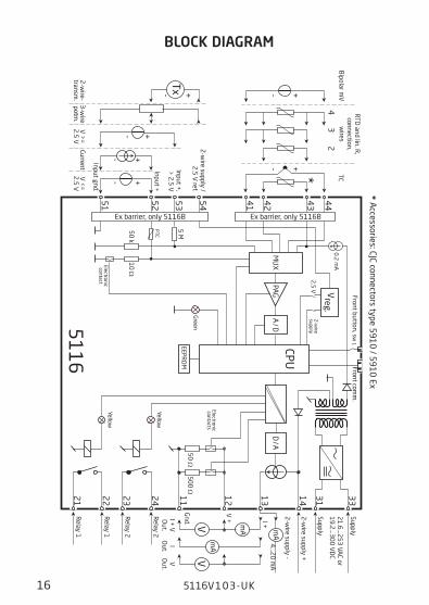
BLOCK DIAGRAM
Supply
Supply
21
.6...2
53
VAC or
19
.2...3
00
VD
C
Gnd.
I + V
O
ut.I
Out.
V
Out.
Relay 2
Relay 2
Relay 1
Relay 1
2-w
ire supply +
2-w
ire supply -
Green
Yellow
Yellow
Electronic contacts
Electronic contact
2-w
ire supply
RTD and lin. R
, connection,
wires
TCB
ipolar mV
2-w
ire supply / 2
.5 V
ref.
Input +,
> 2
.5 V
Input +
Input gnd.
V <
=
2.5
VCurrent
V >
=
2.5
V3
-wire
potm.
2-w
ire-transm
.
Ex barrier, only 5116B Ex barrier, only 5116B
Front comm
.
* Accessories: CJC connectors type 5
91
0 / 5
91
0 Ex
Front button, sw 1
2.5
V
0.2
mA
Vreg.

OnOnOn On OnOn On
100
90
80
70
60
50
40
30
20
10
0 10 20 30 40 50 60 70 80 90 100
100
90
80
70
60
50
40
30
20
10
0 10 20 30 40 50 60 70 80 90 100
OffOff Off OffOff Off
2
1
2
1
2
1
2
1
tt
100
90
80
70
60
50
40
30
20
10
0 10 20 30 40 50 60 70 80 90 100
Off N.O. Off N.O.On N.O.
On N.C. On N.C.Off N.C.
100
90
80
70
60
50
40
30
20
10
0 10 20 30 40 50 60 70 80 90 100
Off N.O. Off N.O.On N.O.
On N.C. On N.C.Off N.C.tt
5116V103-UK 17
RelæenhederRelæenheder
Setpunkt = 50
Hysterese = 10
Hysterese = 10
Setpunkt = 50
Relæenheder
Øvre setpunkt = 60Hysterese = 5
Hysterese = 5Nedre setpunkt = 40
Relæfunktion: Vindue (vist for stigende signal)Kontakt: Lukket inden for vindue = Kontakt: Åben inden for vindue =
Relæenheder
Hysterese = 5
Hysterese = 5Nedre setpunkt = 40
Relæfunktion: Vindue (vist for faldende signal)Kontakt: Lukket inden for vindue = Kontakt: Åben inden for vindue =
Øvre setpunkt = 60
Relæaktion: Stigende Relæaktion: Faldende
12
12
Graphic depiction of relay actions Increasing / Decreasing
Graphic depiction of relay action Window

18 5116V103-UK
5116 CONNECTION TO LOOP LINK
For connection of 5116B to Loop Link, please observe the instructions for instrinsically safe installation.
ACTIVATION OF THE PROCESS CALIBRATION BUTTON
Open the front cover and activate the switch with a pointed object, e.g. a small screwdriver. The switch is placed a little to the right of the LEDs. For further instructions see the description of the process calibration function on page 20.
5 1 1 6
F i l e P r o d u c t I n p u t O u t p u t C o m m u n i c a t i o n L a n g u a g e O p t i o n 0 8 : 3 0 : 0 0
P R e t o p 5 3 3 1
D a t e : 1 9 9 4 - 8 - 1 0
9 4 3 2 0 1 5 9 4
P R e l e c t r o n i c s
A n a l o g i n p u t A n a l o g o u t p u t
S e r i a l n o :
I n p u t t y p e : O u t p u t t y p e : 4 - 2 0 m A
U p s c a l e S e n s o r e r r o r : P t 1 0 0 D I N / I E C
0 . 0 0 - 5 0 . 0 0 C
3 - w i r e
1 . 0 0 s e c - - - - - -
I n p u t r a n g e :
C o n n e c t i o n :
C o l d j u n c t i o n c o m p :
R e s p o n s e t i m e :
T a g n o :
Commu- nication
Loop Link

5116V103-UK 19
Configuration of relay 1 & 2 in PResetParameter Value Description
Type
Off No relay function
Setpoint Relay changes state at a limit on the span
Setpoint window Relay changes state inside a range of the span
Sensor error indication Only works for sensor error
Power indication Relay is active when power is on
Relay units for Relay 1 and Relay 2
% of input span 0...100% of input spanInput units E.g. °C, mV and mA% of output span 0...100% of output spanOutput units mA and V
Setpoint From min. to max. of relay units Setpoint limitSetpiont LOW (setpoint window only) From min. to max. of relay units Lower setpoint in setpoint
windowSetpoint HIGH (setpoint window only) From min. to max. of relay units Higher setpoint in setpoint
window
Hysteresis From 0.1...99.9% of relay units
Difference between setpoint value and reset value. At set-point window the hysteresis is outside the window.
On-delay 0..3600 s
Time from the signal crosses the setpoint threshold until the relay activates. Time is reset at setpoint crossing.
Off-delay 0..3600 s
Time from the signal crosses the hysteresis threshold until the relay deactivates. Time is reset at hysteresis crossing.
ActionIncreasing Activates at increasing signalDecreasing Activates at decreasing signal
Contact
Normally open (N.O.) Contact state before limit is reached
Normally closed (N.C.) Contact state before limit is reached
Open inside window Relay deactivated inside set-point window
Closed inside window Relay activated inside set-point window
Sensor error detection
Contact open Relay deactivatedContact closed Relay activated
Hold Relay state as before sensor error occurred
Off No relay function

20 5116V103-UK
Process calibration 0% and 100% or only 0%(not for RTD and TC input)When the option ”0% and 100% calibration” is actively configured in PReset it is possible to make the following process calibrations. Please note: Input 0% and 100% should be chosen higher than the process-calibrated span.
Process calibration 0% and 100% 1. Apply the actual 0% value. 2. Open the front cover, activate sw. 1 and wait until the green LED lights constantly. 3. Apply the actual 100% value. 4. Activate sw. 1. The LED will start flashing again.The input on PRetrans 5116 has now been scaled according to the actual process values.
When the option ”0% calibration” is actively configured in PReset it is possible to make the following process calibration.
0% process calibration 1. Apply the actual 0% value. 2. Open the front cover and activate sw. 1.The input on PRetrans 5116 has now been scaled according to the actual process values.

5116V103-UK 21
ERROR FUNCTIONS
Error reason
Hardware error indication
Value on ana-logue output
Relay contacts / Yellow LEDs
Green LED
No power supply 0 mA / 0 V Contacts open / LEDs Off Constantly Off
Sensor error As configured As configuredBlinking at
1...2 Hz
RAM checksum check failed *) 0 mA / 0 V Contacts open / LEDs Off Constantly On
EEPROM checksum check failed 0 mA / 0 V Contacts open / LEDs Off Constantly On
Main program stopped 0 mA / 0 V Contacts open / LEDs Off Constantly On
DAC / relay program stopped 0 mA / 0 V Contacts open / LEDs OffDepends on
input **)
*) Error can be reset by power cycling the device or sending a new configuration. **) The green LED is controlled by the main processor.

APPENDIX
FM CONTROL DRAWING NO. 5116QF01
22 5116V103-UK

Rev. AA 2005-07-20
Control Drawing 5116QF01
La (mH) Ca (µF) A,B C,E D,F,G A,B C,E D,F,G
Terminal
Voc (V)
Isc (mA)
Po (mW)
IIC IIB IIA IIC IIB IIA 41,42,43,44 7.5 2.2 4.2 1000 1000 1000 6 36 445
51,52,53 7.5 2.2 4.2 1000 1000 1000 6 36 445 51,52,53,54 28 93.0 650 3 16 31 0.075 0.645 2
Hazardous (Classified) Location Unclassified Location or
Class I, Division 1, Group A,B,C,D Class II, Division 1 Group E, F, G Class III, Division 1 Class I , Zone 0 and 1, Group IIC, IIB, IIA Class II, Zone 20 and 21
Installation notes:
1) The maximum non hazardous location voltage is 250Vac/dc.
2) The installation shall be in accordance with the National Electrical Code NFPA 70, Articles 504 and 505.
3) 5116B is galvanic isolated and does not require grounding
4) For Installation in Div 2 or Zone 2 the 5116B must be installed in an enclosure according to ANSI/ISA S82.
5) Install in Pollution degree 2 or better
6) Use 60 / 75 °C Copper Conductors with Wire Size AWG: (26 – 14).
7) Warning: Substitution of components may impair intrinsic safety.
Simple Apparatus or Intrinsically safe apparatus with entity parameters:
Vmax (Ui) ≥ Vt (Uo) Imax (Ii) ≥ It (Io) Pi ≥ Po Ca ≥ Ccable + Ci La ≥ Lcable + Li
The sum of capacitance and inductance of cable and intrinsic safe equipment must be less or equal to Ca and La
Hazardous (Classified) Location
Class I, Division 2, Group A,B,C,D Class I , Zone 2, Group IIC, IIB, IIA
44
43
42
41
54
53
52
515116B
24
11
12
13
143331
21
22
23
Supp
ly
Supp
ly
24...
.230
VAC
&24
....2
30VD
C
+
-V
T
+
-mV
+
-
5116V103-UK 23
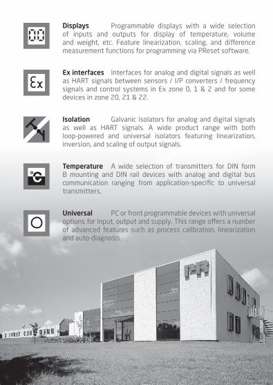
Programmable displays with a wide selection of inputs and outputs for display of temperature, volume and weight, etc. Feature linearization, scaling, and difference measurement functions for programming via PReset software.
Interfaces for analog and digital signals as well as HART signals between sensors / I/P converters / frequency signals and control systems in Ex zone 0, 1 & 2 and for some devices in zone 20, 21 & 22.
Galvanic isolators for analog and digital signals as well as HART signals. A wide product range with both loop-powered and universal isolators featuring linearization, inversion, and scaling of output signals.
PC or front programmable devices with universal options for input, output and supply. This range offers a number of advanced features such as process calibration, linearization and auto-diagnosis.
A wide selection of transmitters for DIN form B mounting and DIN rail devices with analog and digital bus communication ranging from application-specific to universal transmitters.
Displays
Temperature
Isolation
Ex interfaces
Universal

www.prelectronics.fr [email protected]
www.prelectronics.de [email protected]
www.prelectronics.es [email protected]
www.prelectronics.it [email protected]
www.prelectronics.se [email protected]
www.prelectronics.com [email protected]
www.prelectronics.com [email protected]
www.prelectronics.cn [email protected]
www.prelectronics.be [email protected]
Head office
Denmark www.prelectronics.comPR electronics A/S [email protected] 10 tel. +45 86 37 26 77DK-8410 Rønde fax +45 86 37 30 85