5.2.7.5. example of a laboratory quality manual · pdf fileexample of a laboratory quality...
TRANSCRIPT
Page 1/28 5.2.7.5. 04/10
5.2.7.5. EXAMPLE OF A LABORATORY QUALITY MANUAL This example is designed to provide the contractor with general guidelines in creating and maintaining a contractor’s Quality Manual. The QC process requires records for equipment calibrations/verifications. Maintaining records in an orderly manner will assist the District Materials Engineer in quickly determining if the laboratory meets QC/QA requirements. Having the field laboratory fully prepared and the Quality Manual properly maintained represent two items that can keep the start of a project on schedule. It also aids in demonstrating the contractor’s commitment to the QC process. The following records are presented to illustrate what is required in the Quality Manual. Records need not be exactly as illustrated but should supply all necessary information concerning the equipment calibration/verification. NOTE: After calibrating any force-load testing equipment (compression machine) a copy of the certification for the calibration device (proving ring, load cell, etc.) shall be attached to the calibration record. NOTE: All equipment shall be verified immediately after repairs (this may include new or replacement parts, or mechanical or electrical adjustments) that may in any way affect the ability of the equipment to provide accurate readings as established during the calibration/verification process. DISCLAIMER: It is not the intent of these guidelines to endorse manufacturers, suppliers, calibrating services, etc. The examples are used to provide guidance in establishing a properly equipped Quality Manual.

Page 2/28 5.2.7.5. 04/10
LABORATORY QUALITY MANUAL TABLE OF CALIBRATION/VERIFICATION DATES
Revision Date 12/06/96
Equipment – Test Method
Calibration/Verification Intervals (months)
Next Due Date
Mechanical Shakers – KT-2 12 2-9-2000 General Purpose Balances, Scales and Masses – AASHTO M 231 12 1-11-2001
Test Thermometers – KT-17, KT-22 & AASHTO T 231 6 5-03-2000
Testing Machine – KT-22, KT-23 & AASHTO T 22 12
4-28-2000
Sieves – AASHTO M 92 6 4-29-2000 Water tanks – AASHTO M 201 (clean) 24 2/27/2000 Pressure Meter – KT-18 3 Volumetric Meter – KT-19 12 2/11/2000 Slump - KT-21 12 6/24/2000 Unit Mass – KT-20 12 1-14-2000 Capping Material – AASHTO T 231 3 4/03/2000 Reusable Molds – KT-23 12 6/01/2000

Page 3/28 5.2.7.5. 04/10
April 6, 2010
VERIFICATION PROCEDURE FOR MECHANICAL SIEVE SHAKER (Page 1/2)
Purpose: This method provides instructions for checking the length of time the mechanical sieving device must run to meet the tolerances as specified in KT-2 3.3. Inspection Equipment Required: 1. Set of 8" dia. sieves (3/8, 4, 8, 16, 30, 50, 100, 200) 2. Timer 3. Balance, readable to 0.1 g. 4. Sample of fine aggregate. Tolerance: Shaker shall meet the tolerances specified in KT-2 3.3. Procedure: 1. Place sample of aggregate in nested sieves. 2. Place sieves in shaker & set timer for 4 minutes. 3. Check sieving adequacy as described in KT-2 6.3. 4. If 4-minute setting doesn't meet specification increase time by 30 seconds intervals until specification is met.

Page 4/28 5.2.7.5. 04/10
April 6, 2010
VERIFICATION RECORD FOR MECHANICAL SHAKER (Page 2/2)
Verified By: Date:
Equipment: Mechanical Shaker Verif. Frequency: 12 months
Previous Verif. Date: Next Due Date:
Verification Equipment Used:
Verif. Equipment Identification:
Verif. Procedure Used:
1 Weight of Sample in grams.
2 Weight of material, in grams, passing sieve after one minute of hand shaking as described in KT 2.
3 Percent of material passed.

Page 5/28 5.2.7.5. 04/10
CALIBRATION OF BALANCES
Page 1/3
March 30, 1995
ABC PACKERS INC. SCOPE OF WORK FOR LABORATORY BALANCES: Definitions are on next page. 1. The weighing environment is checked for anything that would effect the ability of the balance to weigh accurately for example: direct air currents, direct sunlight, objects stuck under the balance or magnets in close proximity to the balance. 2. The balance is checked for errors in zero, sensitivity, calibration, comer load, linearity, repeatability and tare accuracy. Any errors are noted. 3. The balance is thoroughly cleaned and disassembled. Parts subject to wear or damage are inspected. On mechanical balances, this includes but is not limited to knife edges, arrestment mechanism, switches, pan brake assemblies and weight lifting assemblies. On electronic balances, the measuring cell and flextures are inspected. Circuit boards and switches are inspected for contamination and corrosion. 4. Any errors noted in step two are corrected through adjustments or replacement of minor parts. If the balance cannot be returned to factory specifications through this method, the using personnel are consulted as to the need for further repairs. 5. The balance is reassembled and final checks are made as in step two. Final calibration adjustments are made. 6. Applicable GLP log books are annotated. A. All tests are performed with Class 1 stainless steel weights traceable to the NIST and are calibrated at least annually. B. A certificate of weight traceability to the NIST is provided to each functional area. This certificate lists all the balances serviced in that area and the serial number of the weights used, their calibration date, the NIST trace number and the technician calibration number.
Page 6/28 5.2.7.5. 04/10
Page 2/3 DEFINITIONS: Balance = Weighing device, generally with a resolution of 1 part in 12,000 or greater. Top loading balances will have a resolution of up to 1 part in 1,200,000 and sensitivity down to 1 milligram i.e. 1200.000 gram +/- .001 gram. Analytical balances will have a resolution of up to 1 part in 4,100,000 and sensitivity down to .0 1 milligram i.e. 41.00000 gram +/- .00001 gram. Micro-balances will have a resolution of up to 1 part in 200,000,000 sensitivity down to .0000001 gram. Calibration = The accuracy of the balance, usually at full capacity, as compared to known standards. Class 1 = A published standard for weights from the NIST. The standard dictates the materials, configuration and tolerance of the weights. Corner loads = The deviation of the indicated weight between the center of the pan and the front, rear, left and right of the pan. This test is performed at 2/3 of maximum capacity. Electronic Balance = A balance deriving it's indicated weight from a force restoration coil measuring cell or high resolution load cell. Factory specifications = The balance manufacturers specifications for all adjustments, usually +/- 1 final count (least significant digit). Flexture = Parts of the measuring cell. The accuracy of all adjustments is dependent on the condition of these parts. GLP = Acronym. Stands for Good Laboratory Practices. Laboratories under this standard must establish a plan for weighing accuracy control. Knife edges = The pivot points of the balance beam in mechanical balances. Mechanical Balance = A high resolution balance deriving it's indicated readout from the mechanical movement of a balance beam and a system of built in standard comparison weights. NIST = Acronym. Stands for the National Institute for Standards and Technology. This is the new name for the National Bureau of Standards (NBS). Pan brake = Part of a mechanical analytical balance used to stop pan swing when the balance is arrested.

Page 7/28 5.2.7.5. 04/10
Page 3/3 DEFINITIONS, CONTINUED Repeatability = Test performed on all balances to determine if it indicates the same weight and returns to zero every time a weight is applied to and removed from the pan. This test is normally performed with a weight that is near the normal usage of the balance if known or near the mid-range of the balance. The weight is placed on the balance a minimum of three times to get a plus or minus reading. Sensitivity = On mechanical balances this test determines the accuracy of the beam travel or optical range of the balance. On electronic balances this is the lightest weight that the balance will accurately respond to. Tare accuracy = This test is used on mechanical balances to determine if the balance reads the same with or without the tare.
Page 8/28 5.2.7.5. 04/10
April 6, 2010
VERIFICATION PROCEDURE FOR THERMOMETERS (Page 1/2)
FORM DATE: March 29, 1996 Purpose: This method provides instructions for verifying the settings on general-purpose thermometers. Inspection Equipment Required: 1. A calibrated thermometer graduated in 2.0oF (1.0oC) increments having a range which includes the temperature range to be checked. 2. A clothespin to hold the thermometer in such a manner as to enable the operator to read the scale easily. 3. A container well to retain heat for constant temperature readings. 4. A hot plate to heat the liquid (oil) in the container well. Procedure: 1. Place the thermometer inside the container well with the clothespin attached to the thermometer. 2. Take the first reading when the temperature has stabilized. 3. Take as many readings as necessary to determine the "laboratory thermometer setting" vs "actual calibrated reading."

Page 9/28 5.2.7.5. 04/10
VERIFICATION RECORD FOR THERMOMETERS (Page 2/2)
Verified By: Date: Equipment: Thermometers Verif. Frequency: 6 months Previous Verif. Date: Next Due Date: Verification Equipment Used: Verif. Equipment Identification:
Verif. Procedure Used: See procedure (page 1/2)
AASHTO Procedure Equipment Thermometer Calibrated Thermometer
Identification Reading in o F Identification Reading in o F

Page 10/28 5.2.7.5. 04/10
REPORT FORM FOR COMPRESSION MACHINE (Page 1/2)
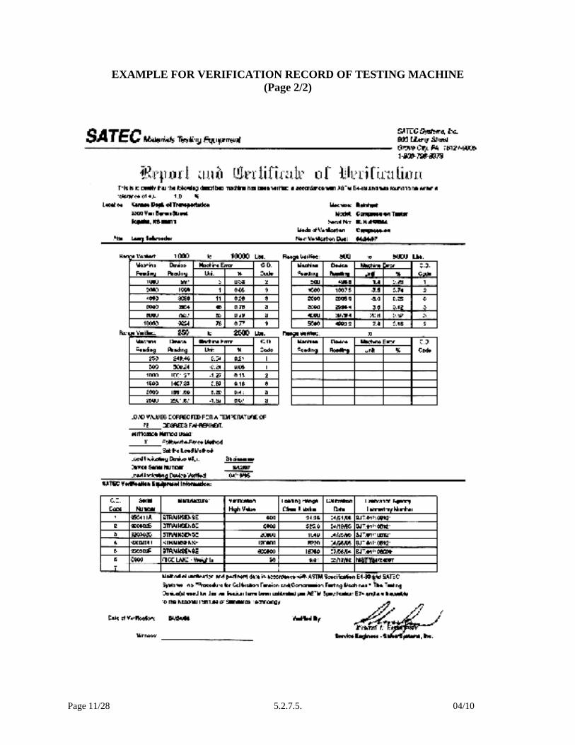
Calibration performed according to ASTM E 4 (latest publication). - Must provide Load Cell readings, Compression Machine readings and
percent error for each force reading. CONTRACTOR: DATE: LOCATION: CALIBRATION SERVICE NAME: CALIBRATOR: NEXT LOAD CELL/RING CALIBRATION DATE: LOWER RANGE OF DEVICE (CLASS A VALUE): UPPER RANGE OF DEVICE: TEMPERATURE CORRECTION FACTOR USED: TESTING MACHINE MANUFACTURER: TESTING MACHINE SERIAL NUMBER: CALIBRATION WITNESS: CALBIRATOR SIGNATURE: COMMENTS:
Page 11/28 5.2.7.5. 04/10
EXAMPLE FOR VERIFICATION RECORD OF TESTING MACHINE (Page 2/2)

Page 12/28 5.2.7.5. 04/10
VERIFICATION PROCEDURE FOR SIEVES (Page 1/2)
Purpose: This method provides instructions for checking the physical condition of laboratory tests sieves ranging in size 3 in. (75 mm) to #200 (0.075 mm). Inspection Equipment Required: 1. A caliper readable to 0.01 mm (use for #4 or coarser). Tolerances: Sieves shall meet physical requirements specified in AASHTO M 92 (ASTM E11). Procedure: (Steps 1 & 2 apply to sieves having openings greater than 4.75 mm) 1. Select an adequate number of individual sieve openings (3 or 4) along a 45o line. Measure and record the sieve openings to verify that the size opening indicated on the label is correct. 2. Repeat step 1, rotating the sieve 90o. 3. Inspection the general condition of the sieve. Check the frame and solder joints for cracks or holes (check for pinholes in the finer sieves). 4. Make sure the sieves have an appropriate label. 5. Check for tightness of the wires on each individual sieve.
Page 13/28 5.2.7.5. 04/10
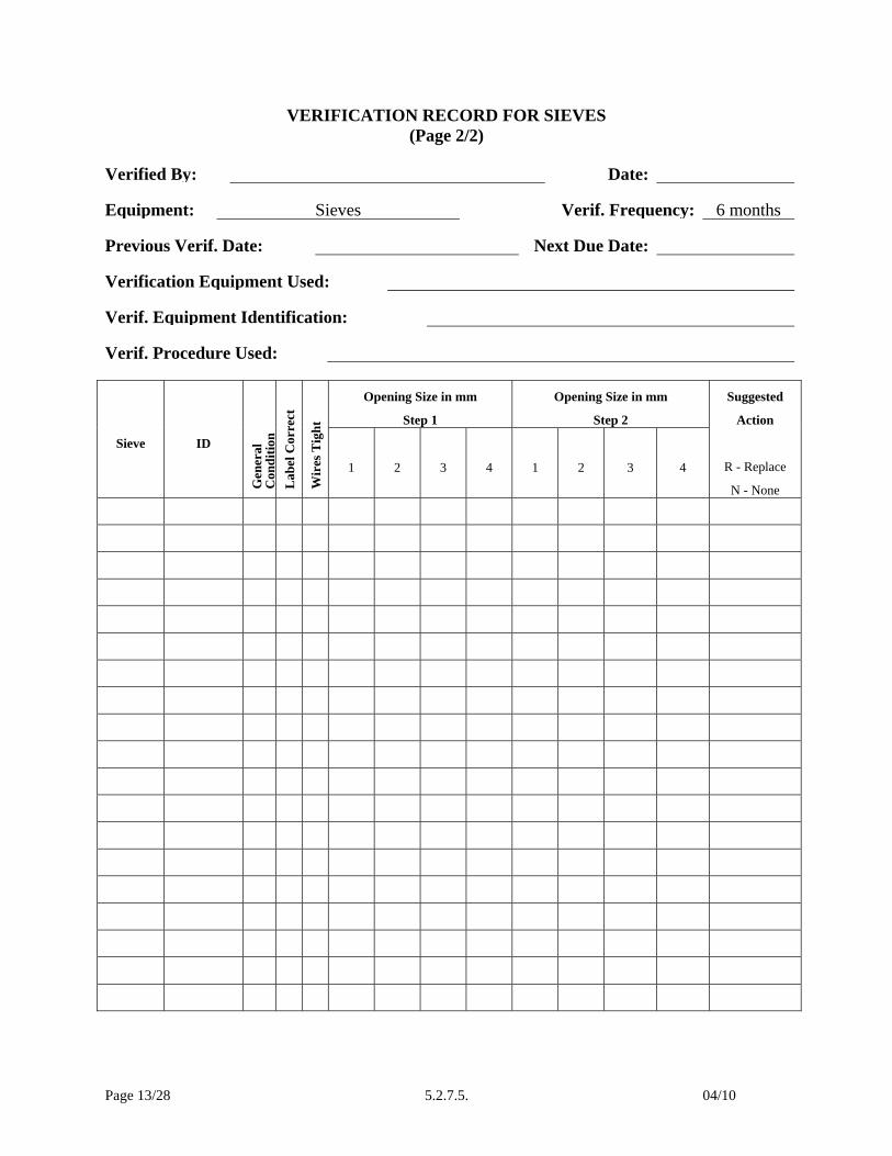
VERIFICATION RECORD FOR SIEVES (Page 2/2)
Verified By: Date: Equipment: Sieves Verif. Frequency: 6 months Previous Verif. Date: Next Due Date: Verification Equipment Used: Verif. Equipment Identification:
Verif. Procedure Used:
Sieve
ID
Gen
eral
C
ondi
tion
Lab
el C
orre
ct
Wir
es T
ight
Opening Size in mm
Step 1
Opening Size in mm
Step 2
Suggested
Action
R - Replace
N - None
1
2
3
4
1
2
3
4

Page 14/28 5.2.7.5. 04/10
VERIFICATION PROCEDURE FOR WATER TANKS (Page 1/2)
Purpose: This method provides instructions for checking water storage tanks. Inspection Equipment Required: 1. Calibrated thermometer, graduated in 0.5oC divisions. Tolerances: 1. Storage Tanks shall meet the tolerances specified in the test method. Procedure: (Tanks) Drain and clean the water storage tanks in intervals not to exceed 24 months. 1. Visually inspect the tanks, note any crack or holes observed, and repair as needed. 2. Refill each tank with water containing 3 g/L of calcium hydroxide. 3. Thoroughly stir the water in the tanks at intervals not to exceed one month to help replace calcium ions that have depleted. - Record the date stirred. (Recording Thermometer) 1. Check the recording thermometer for accuracy at least every six months. 2. Place calibrated thermometer in water adjacent to the recording thermometer. 3. Correction factor shall be provided if differences in the observed readings exceed 1oC. Record this verification of the thermometer as described in the section covering verification of thermometers.

Page 15/28 5.2.7.5. 04/10
VERIFICATION RECORD FOR WATER TANKS (Page 2/2)
Verified By: Date:
Equipment: Water Tanks Verif. Frequency: 24 months
Previous Verif. Date: Next Due Date:
Verification Equipment Used:
Verif. Equipment Identification:
Verif. Procedure Used:
Water Stirred in Tanks
1st year 2nd year
Month 1
Month 2
Month 3
Month 4
Month 5
Month 6
Month 7
Month 8
Month 9
Month 10
Month 11
Month 12
Tanks Drained and Cleaned:
Condition of tanks
Refilled with 3 g/L hydrated lime (calcium hydroxide)
Was the thermometer checked for accuracy every six months?
Page 16/28 5.2.7.5. 04/10
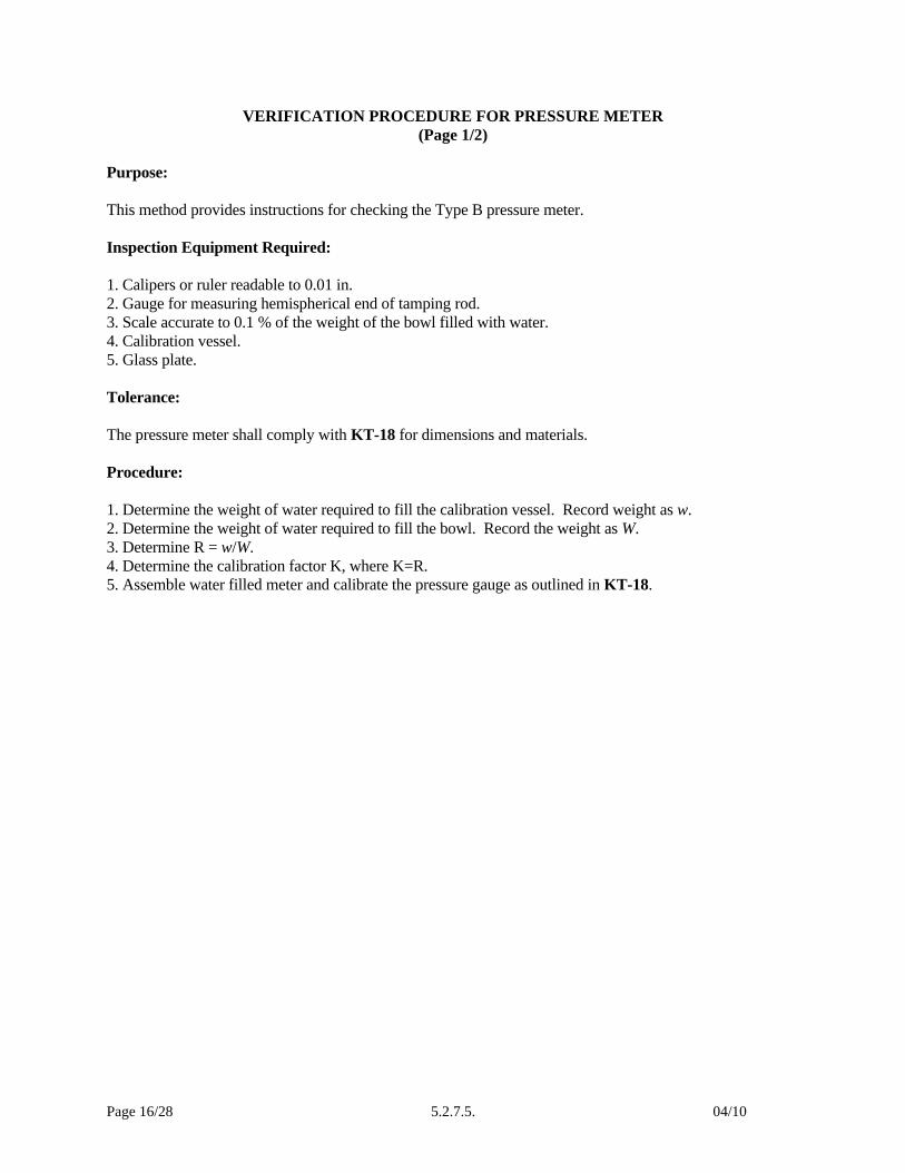
VERIFICATION PROCEDURE FOR PRESSURE METER (Page 1/2)
Purpose: This method provides instructions for checking the Type B pressure meter. Inspection Equipment Required: 1. Calipers or ruler readable to 0.01 in. 2. Gauge for measuring hemispherical end of tamping rod. 3. Scale accurate to 0.1 % of the weight of the bowl filled with water. 4. Calibration vessel. 5. Glass plate. Tolerance: The pressure meter shall comply with KT-18 for dimensions and materials. Procedure: 1. Determine the weight of water required to fill the calibration vessel. Record weight as w. 2. Determine the weight of water required to fill the bowl. Record the weight as W. 3. Determine R = w/W. 4. Determine the calibration factor K, where K=R. 5. Assemble water filled meter and calibrate the pressure gauge as outlined in KT-18.

Page 17/28 5.2.7.5. 04/10
VERIFICATION RECORD FOR PRESSURE METER (Page 2/2)
Verified By: Date: Equipment: Type B pressure meter Verif. Frequency: 3 months Previous Verif. Date: Next Due Date: Verification Equipment Used: Verif. Equipment Identification:
Verif. Procedure Used:
W = W= R = K= Air content gradations verified as in KT 18?
Yes / no
Tamping Rod Diameter, inches 1) 5/8” 2)Length, inches At least 16”Hemispherical end Yes / noAction recommended

Page 18/28 5.2.7.5. 04/10
VERIFICATION PROCEDURE FOR VOLUMETRIC METER (Page 1/2)
Purpose: This method provides instructions for checking the volumetric meter. Inspection Equipment Required: 1. Calipers or ruler readable to 0.01 in. 2. Gauge for measuring hemispherical end of tamping rod. 3. Scale accurate to 0.1 % of the weight of the bowl filled with water. 4. Calibrated cup. 5. Thermometer Tolerance: The volumetric meter shall comply with KT-20 for dimensions and materials. Procedure: 1. Determine the volume of the bowl, with an accuracy of at least 0.1 % by weighing the amount of water required to fill it at room temperature, and dividing this weight by the unit weight of water at the same temperature. 2. Determine the accuracy of the gradations on the neck, by filling the assembled meter with water to a pre-selected air-content gradation and then determining the quantity of 21.1oC (70oF) water required to fill the meter to the zero mark. The added water shall be within ± 0.1 % volume of the measuring bowl. Repeat this procedure 3 times. 3. Determine the volume of the calibrated cup by the method outlined in KT-20.
Page 19/28 5.2.7.5. 04/10
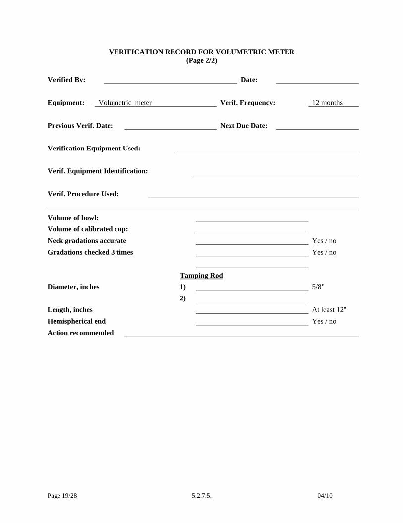
VERIFICATION RECORD FOR VOLUMETRIC METER (Page 2/2)
Verified By: Date: Equipment: Volumetric meter Verif. Frequency: 12 months Previous Verif. Date: Next Due Date: Verification Equipment Used: Verif. Equipment Identification:
Verif. Procedure Used:
Volume of bowl: Volume of calibrated cup: Neck gradations accurate Yes / noGradations checked 3 times Yes / no
Tamping RodDiameter, inches 1) 5/8” 2) Length, inches At least 12”Hemispherical end Yes / noAction recommended
Page 20/28 5.2.7.5. 04/10
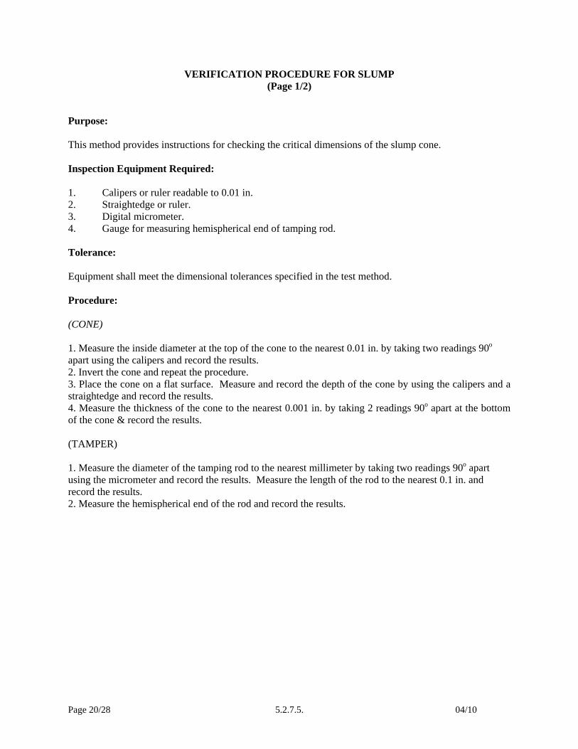
VERIFICATION PROCEDURE FOR SLUMP (Page 1/2)
Purpose: This method provides instructions for checking the critical dimensions of the slump cone. Inspection Equipment Required: 1. Calipers or ruler readable to 0.01 in. 2. Straightedge or ruler. 3. Digital micrometer. 4. Gauge for measuring hemispherical end of tamping rod. Tolerance: Equipment shall meet the dimensional tolerances specified in the test method. Procedure: (CONE) 1. Measure the inside diameter at the top of the cone to the nearest 0.01 in. by taking two readings 90o apart using the calipers and record the results. 2. Invert the cone and repeat the procedure. 3. Place the cone on a flat surface. Measure and record the depth of the cone by using the calipers and a straightedge and record the results. 4. Measure the thickness of the cone to the nearest 0.001 in. by taking 2 readings 90o apart at the bottom of the cone & record the results. (TAMPER) 1. Measure the diameter of the tamping rod to the nearest millimeter by taking two readings 90o apart using the micrometer and record the results. Measure the length of the rod to the nearest 0.1 in. and record the results. 2. Measure the hemispherical end of the rod and record the results.

Page 21/28 5.2.7.5. 04/10
VERIFICATION RECORD FOR SLUMP
(Page 2/2) Verified By: Date: Equipment: Slump Cone and Tamping Rod Verif. Frequency: 12 months Previous Verif. Date: Next Due Date: Verification Equipment Used: Verif. Equipment Identification:
Verif. Procedure Used:
Cone SpecificationTop inside diameter, inches 1) 4” +/- 1/8” 2)
Bottom inside diameter, inches 1) 8” +/- 1/8” 2)
Depth of Cone , inches 1) 12” +/- 1/8”
Wall thickness, inches 1) Not less than 0.045”
2)
Tamping RodDiameter, inches 1) 5/8” 2) Length, inches Approx. 24” Hemispherical end Yes / no Action recommended

Page 22/28 5.2.7.5. 04/10
VERIFICATION PROCEDURE FOR UNIT MASS (Page 1/2)
Purpose: This method provides instructions for calibrating measures used in obtaining unit mass. Inspection Equipment Required: 1. Balance conforming to Part V 5.9. Sampling and Test Methods Forward 2. 0.01 in (0.25 mm) feeler gauge. 3. 1/4 in (6 mm) thick glass plate at least 1 in (25 mm) larger than the measure. 4. Water pump or chassis grease. 5. Thermometer. Tolerance: The bowls and measures shall conform to the dimensions found in KT-20. Procedure: 1. Place glass plate on rim and attempt to insert feeler gauge. 2. Fill measure with room temperature water and cover in such a way as to dispel air bubbles and excess water. 3. Determine the mass of water in the measure. 4. Determine the temperature of the water, and obtain its density from KT-15. 5. Calculate the volume, V, of the measure by dividing the mass of the water required to fill the measure by its density. 6. Calculate the factor for the measure (1/V) by dividing the density of the water by the mass required to fill the measure.
Page 23/28 5.2.7.5. 04/10
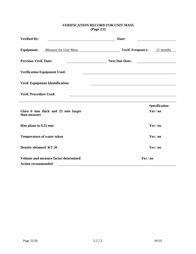
VERIFICATION RECORD FOR UNIT MASS (Page 2/2)
Verified By: Date: Equipment: Measure for Unit Mass Verif. Frequency: 12 months Previous Verif. Date: Next Due Date: Verification Equipment Used: Verif. Equipment Identification: Verif. Procedure Used:
SpecificationGlass 6 mm thick and 25 mm larger than measure
Yes / no
Rim plane to 0.25 mm Yes / no Temperature of water taken Yes / no Density obtained KT 20 Yes / no Volume and measure factor determined Yes / no Action recommended

Page 24/28 5.2.7.5. 04/10
VERIFICATION PROCEDURE FOR CAPPING MATERIAL (Page 1/3)
Purpose:
To ensure that capping material meets Quality requirements. Inspection Equipment Required: 1. Testing Machine 2. Melting Pot capable of holding a temperature between 265 to 290oF (129 to 143oC) 3. Three 2-inch (50 mm) cube molds 4. Ladle or other suitable pouring device 5. .002 feeler gauge and bar 6. Mineral oil 7. Straight bar Tolerance: All capping material shall conform to the following strength and thickness requirements:
Cylinder Compressive Strength psi (MPa)
Minimal Strength of Capping Material Maximum Average Thickness of Cap
Maximum Thickness Any Part of the Cap
500 to 7000 psi (3.5 to 50 MPa)
5000 psi (35 MPa) or cylinder strength, whichever is greater
1/4 inch (6 mm)
5/16 inch (8 mm)
Greater than 7000 psi (50 MPa)
Compressive strength not less than cylinder strength
1/8 inch (3 mm)
3/16 inch (5 mm)

Page 25/28 5.2.7.5. 04/10
VERIFICATION PROCEDURE FOR CAPPING MATERIAL
(Page 2/3) Procedure: 1. Melt sufficient capping material in melting pot until it reaches between 265 to 290oF (129 to 143oC). 2. Bring the mold parts to 68 to 86oF (20 to 30oC). 3. Coat all surfaces of cube molds with mineral oil. 4. After stirring thoroughly, use Ladle to begin casting the cubes. Quickly fill all three molds until the molten material reaches the top of the filling hole. 5. Allow time for maximum shrinkage to occur due to cooling and solidification to occur (approximately 15 minutes) and refill each mold with molten material. 6. After solidification occurs remove the cubes from the molds without breaking off the knob. 7. Remove oil, sharp edges, and fins from cubes. 8. Allow cubes to harden for a minimum of two hours before breaking. 9. Test the cubes in the compression machine and calculate the compressive strength.
Page 26/28 5.2.7.5. 04/10
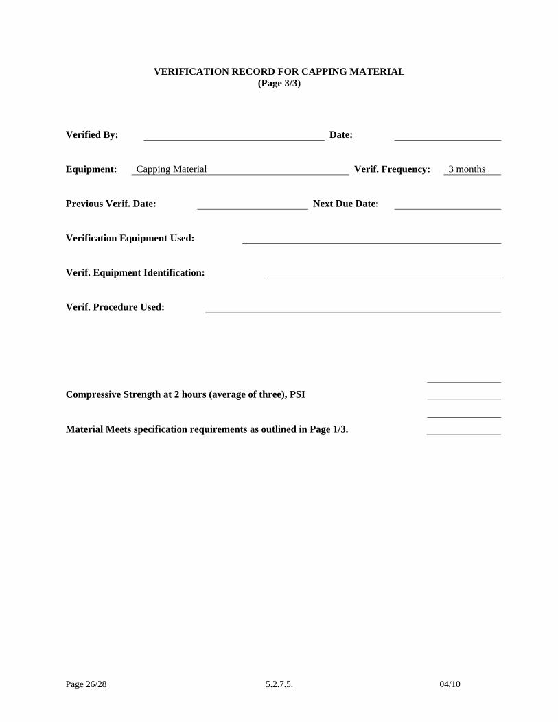
VERIFICATION RECORD FOR CAPPING MATERIAL (Page 3/3)
Verified By: Date:
Equipment: Capping Material Verif. Frequency: 3 months
Previous Verif. Date: Next Due Date:
Verification Equipment Used:
Verif. Equipment Identification:
Verif. Procedure Used:
Compressive Strength at 2 hours (average of three), PSI
Material Meets specification requirements as outlined in Page 1/3.
Page 27/28 5.2.7.5. 04/10
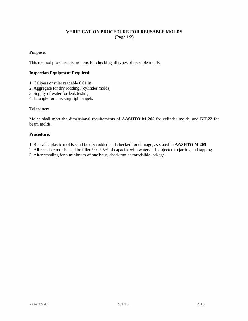
VERIFICATION PROCEDURE FOR REUSABLE MOLDS (Page 1/2)
Purpose: This method provides instructions for checking all types of reusable molds. Inspection Equipment Required: 1. Calipers or ruler readable 0.01 in. 2. Aggregate for dry rodding, (cylinder molds) 3. Supply of water for leak testing 4. Triangle for checking right angels Tolerance: Molds shall meet the dimensional requirements of AASHTO M 205 for cylinder molds, and KT-22 for beam molds. Procedure: 1. Reusable plastic molds shall be dry rodded and checked for damage, as stated in AASHTO M 205. 2. All reusable molds shall be filled 90 - 95% of capacity with water and subjected to jarring and tapping. 3. After standing for a minimum of one hour, check molds for visible leakage.

Page 28/28 5.2.7.5. 04/10
VERIFICATION RECORD FOR REUSABLE MOLDS (Page 2/2)
Verified By: Date:
Equipment: Reusable Molds Verif. Frequency: 12 months
Previous Verif. Date: Next Due Date:
Verification Equipment Used:
Verif. Equipment Identification:
Verif. Procedure Used:
Inside Diameter
Inside Height
Top and Bottom Planes Perpendicular to Axis
Diameter Variation Within +-2% (% of variation)
Satisfactory condition after dry rodding
Leakage
Materials React With or Injurious to Concrete