5301064 model no. lg-1500-303 12 volt lawn & garden ...fm522).pdf · 12 volt lawn & garden...
TRANSCRIPT
Page 1
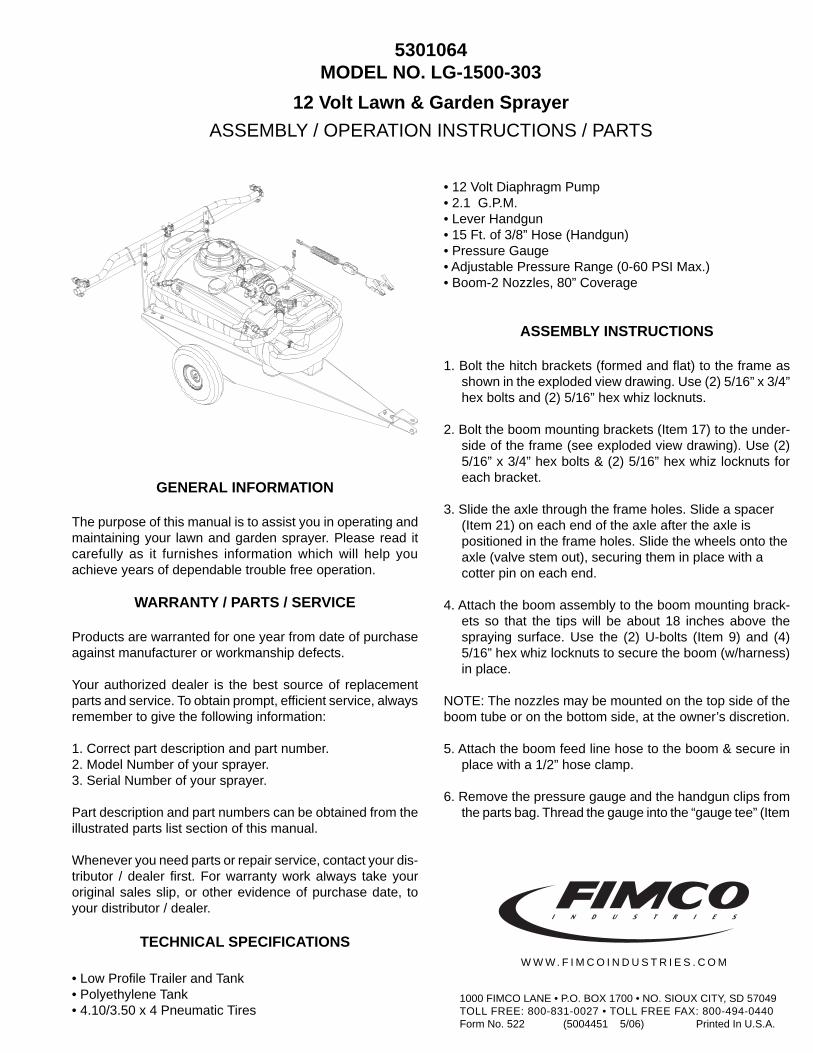
12 Volt Lawn & Garden Sprayer
ASSEMBLY / OPERATION INSTRUCTIONS / PARTS
GENERAL INFORMATION
The purpose of this manual is to assist you in operating andmaintaining your lawn and garden sprayer. Please read itcarefully as it furnishes information which will help youachieve years of dependable trouble free operation.
WARRANTY / PARTS / SERVICE
Products are warranted for one year from date of purchaseagainst manufacturer or workmanship defects.
Your authorized dealer is the best source of replacementparts and service. To obtain prompt, efficient service, alwaysremember to give the following information:
1. Correct part description and part number.2. Model Number of your sprayer.3. Serial Number of your sprayer.
Part description and part numbers can be obtained from theillustrated parts list section of this manual.
Whenever you need parts or repair service, contact your dis-tributor / dealer first. For warranty work always take youroriginal sales slip, or other evidence of purchase date, toyour distributor / dealer.
TECHNICAL SPECIFICATIONS
• Low Profile Trailer and Tank• Polyethylene Tank• 4.10/3.50 x 4 Pneumatic Tires
• 12 Volt Diaphragm Pump• 2.1 G.P.M.• Lever Handgun• 15 Ft. of 3/8” Hose (Handgun)• Pressure Gauge• Adjustable Pressure Range (0-60 PSI Max.)• Boom-2 Nozzles, 80” Coverage
ASSEMBLY INSTRUCTIONS
1. Bolt the hitch brackets (formed and flat) to the frame asshown in the exploded view drawing. Use (2) 5/16” x 3/4”hex bolts and (2) 5/16” hex whiz locknuts.
2. Bolt the boom mounting brackets (Item 17) to the under-side of the frame (see exploded view drawing). Use (2)5/16” x 3/4” hex bolts & (2) 5/16” hex whiz locknuts foreach bracket.
3. Slide the axle through the frame holes. Slide a spacer(Item 21) on each end of the axle after the axle ispositioned in the frame holes. Slide the wheels onto theaxle (valve stem out), securing them in place with acotter pin on each end.
4. Attach the boom assembly to the boom mounting brack-ets so that the tips will be about 18 inches above thespraying surface. Use the (2) U-bolts (Item 9) and (4)5/16” hex whiz locknuts to secure the boom (w/harness)in place.
NOTE: The nozzles may be mounted on the top side of theboom tube or on the bottom side, at the owner’s discretion.
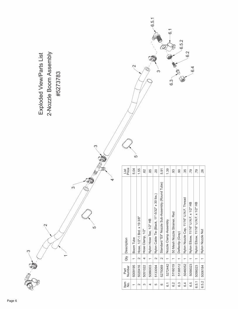
5. Attach the boom feed line hose to the boom & secure inplace with a 1/2” hose clamp.
6. Remove the pressure gauge and the handgun clips fromthe parts bag. Thread the gauge into the “gauge tee” (Item
5301064MODEL NO. LG-1500-303
1000 FIMCO LANE • P.O. BOX 1700 • NO. SIOUX CITY, SD 57049TOLL FREE: 800-831-0027 • TOLL FREE FAX: 800-494-0440Form No. 522 (5004451 5/06) Printed In U.S.A.
W W W . F I M C O I N D U S T R I E S . C O M

Page 2
Tip Spray Pressure Capacity GALLONS PER ACRE - BASED ON WATERNo. Height (PSI) (GPM) 1 MPH 2 MPH 3 MPH 4 MPH 5 MPH 7.5 MPH 10 MPH
10 .30 44 22 14.9 11.1 8.9 5.9 4.53 18" 20 .42 63 31.5 20.9 15.7 12.6 8.4 6.3
30 .52 76 38 26 19.3 15.4 10.3 7.740 .60 90 45 30 22 17.8 11.8 8.9
Tip Spray Pressure Capacity GALLONS PER 1000 SQ. FT. - BASED ON WATERNo. Height (PSI) (GPM) 1 MPH 2 MPH 3 MPH 4 MPH 5 MPH 7.5 MPH 10MPH
10 .30 1.01 .50 .34 .254 .204 .135 .1033 18" 20 .42 1.4 .72 .48 .36 .29 .19 .14
30 .52 1.74 .87 .596 .44 .35 .236 .176
40 .60 2.06 1.00 .688 .50 .408 .27 .20
Tip Spray Pressure Capacity GALLONS PER 100 SQ. FT. - BASED ON WATERNo. Height (PSI) (GPM) 1 MPH 2 MPH 3 MPH 4 MPH 5 MPH 7.5 MPH 10MPH
10 .30 .10 .050 .034 .025 .020 .013 .0103 18" 20 .42 .14 .072 .048 .036 .029 .019 .014
30 .52 .174 .087 .059 .044 .035 .0236 .01740 .60 .206 .1 .068 .050 .040 .027 .020
Tip Chart
Speed in M.P.H. Time Required in Seconds to Travel a distance of;(Miles Per Hour) 100 ft. 200 ft. 300 ft.
1.0 68 136 2052.0 34 68 1023.0 23 45 684.0 17 34 515.0 14 27 416.0 11 23 347.0 9.7 19 298.0 8.5 17 269.0 7.6 15 23
10 6.8 14 20
Speed Chart
5.1) in the pump sub-assembly drawing) using a goodgrade of thread sealant to prevent any leaks. Attach the(2) handgun clips to the side of the tank with the screwsprovided.
7. Join the red wire of the two-wire cable to a “hot” connec-tion on the vehicle, such as a switch, ammeter, or thepositive battery post. The brown wire (of the two-wirecable) should be grounded or connected to the negativebattery post.
Read the operating instructions and then run the sprayerusing only water for testing. Initially begin spraying by clos-ing the bypass regulating valve and opening the shut-off valveto the boom. This will enable the air in the line to be elimi-nated through the tips, while building pressure. When ev-erything tests all right (no leaks, good pressure), add thedesired chemicals mixture and water combination and startthe spraying operation.
OPERATION
This sprayer is designed to be towed behind a gardentractor.
The pumping system draws solution from the tank, throughthe strainer and to the pump. The pump forces the solutionunder pressure to the boom nozzles.
The pump has a pressure switch which will shut the pumpoff when it reaches 60 PSI.
Pressure may be decreased by opening the bypass valve(Hi-Lo). The more it is opened, the lower the pressure willbe.
The nozzles on the boom will spray an 80 inch wide swath.Check the nozzle spray pattern by spraying water on a con-crete surface. Raise the boom to get more spray patternoverlap if desired.
Regularly clean the intake tube screen by removing thescreen from the intake tube. The screen may now be tappedor flushed with clear water for cleaning.
WARNING: Some chemicals will damage the pump valvesif allowed to soak untreated for a length of time. Always flushthe pump with water after use. Do not allow chemicals to sitin pump for extended times of idleness. Follow chemicalmanufacturers instructions on disposal of all waste water fromthe sprayer.
CALIBRATION
Chemical labels may show application rates in gallons peracre, gallons per 1000 square feet or gallons per 100 squarefeet. You will note that the tip chart shows all three of theserating systems.
Once you know how much you are going to spray then de-termine (from the tip chart) the spraying pressure (PSI), andthe spraying speed (MPH).
Conditions of weather and terrain must be considered whensetting the sprayer. Do not spray on windy days. Protectiveclothing must be worn in some cases. Be sure to read thechemical label carefully.Determining the proper speed of the tractor can be done bymarking off 100, 200 and 300 feet. The speed chart indi-cates the number of seconds it takes to travel the distances.Set the throttle and with a running start travel the distances.Adjust the throttle until you travel the distances in the num-ber of seconds indicated by the speed chart. Once you havereached the throttle setting needed, mark the throttle loca-tion so you can stop and go again (returning to the samespeed).Add water and proper amount of chemical to tank and driveto the starting place for spraying.
When you are ready to spray, turn the boom valve to the“on” position. This will start solution spraying from the tips.The pressure will decrease slightly when the boom isspraying.
Page 3
AFTER SPRAYING
After use fill the sprayer part way with water. Start the sprayerand allow clear water to be pumped through the plumbingsystem and out through the spray nozzles.
Refill the tank about half full with plain water and use a chemi-cal neutralizer such as Nutra-Sol or equivalent and repeatcleaning instructions. Flush the entire sprayer with the neu-tralizing agent. Follow the chemical manufacturers disposalinstructions of all wash or rinsing water.Remove tips and screens from the boom. Wash tips thor-oughly with water or cleaning solution (appropriate for chemi-cal used). Blow out orifice, clean and dry. If orifice remainsclogged clean it with a fine bristle (not wire) brush, or with atooth pick. Do not damage the orifice. Water rinse and drytips before storing.
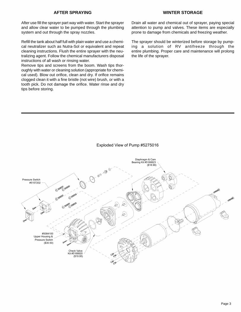
WINTER STORAGE
Drain all water and chemical out of sprayer, paying specialattention to pump and valves. These items are especiallyprone to damage from chemicals and freezing weather.
The sprayer should be winterized before storage by pump-ing a solution of RV antifreeze through theentire plumbing. Proper care and maintenance will prolongthe life of the sprayer.

Page 4

Page 5
Page 6