53131 operating guide
TRANSCRIPT

8/4/2019 53131 Operating Guide
http://slidepdf.com/reader/full/53131-operating-guide 1/196
Operat ingGuide
HP 53131A/132A 225 MHz
Universa l Coun ter

8/4/2019 53131 Operating Guide
http://slidepdf.com/reader/full/53131-operating-guide 2/196

8/4/2019 53131 Operating Guide
http://slidepdf.com/reader/full/53131-operating-guide 3/196
HP 53131A/132A 225 MHz
Universa l Coun ter
Opera t ing GuideThis guide describes how to use t he HP 53131A/132A 225 MHz Universal
Count er. The inform at ion in th is guide applies to instr um ents h aving the
nu mber prefix listed below, unless a ccompa nied by a “Manu al Upda ting
Changes” package indicating otherwise.
SERIAL P REF IX N UMB ER: 3313A to 3736A (H P 53131A)
3352A to 3736A (HP 53132A)

8/4/2019 53131 Operating Guide
http://slidepdf.com/reader/full/53131-operating-guide 4/196
Hewlet t -Packard Company 7.NC.NL.A.11.03.97.R1.P .CW6FCSanta Clara Division5301 Stevens Creek BoulevardSant a Clara , California 95052-8059
©Copyright Hewlett-PackardCompany 1999
All Rights Reserved.Reproduction, ada pta tion, ortran slations without priorwritten permission isprohibited, except as allowedunder the copyright laws.
Prin ted: May 1999
Printed in USA
Manual part number53131-90055
Certif icationand Warranty
Certif ication
Hewlett-Packard Companycertifies that this pr oduct metits published specification at t hetime of shipment from t hefactory. Hewlett-Packar dfurther certifies that itscalibration measu rements ar etraceable to the United StatesNational Institute of Standa rds
and Technology (formerlyNational Bureau of Standar ds),to the extent allowed by theInst itut e’s calibrat ion facility,and to the calibrat ion facilitiesof other Internat ionalStandar ds Organizationmembers.
Warranty
HP warran t s HP hardware ,accessories and su pplies against
defects in mat erials andworkman ship for a period of th ree years from date of shipmen t. If HP receives noticeof such defects du ring t hewarran ty period, HP will, at itsoption, either r epair or replaceproducts which pr ove to bedefective. Replacement productsmay be eith er new or like-new.
HP warrants that HP softwarewill not fail to execut e its
program ming instr uctions, forth e period specified above, dueto defects in mater ial andworkman ship when properlyinsta lled and used. If HPreceives n otice of such defectsduring the warr ant y period, HPwill replace software m ediawhich does not execute itsprogramm ing instructions du eto such defects.
For detailed warranty
information, see back matter.
Safety Considerat ions
General
This product a nd r elateddocumenta tion m ust bereviewed for familiarizat ionwith this safety markings andinstr uctions before operation.
Before CleaningDisconnect th e product fromoperating power beforecleaning.
Warning S ymbols That MayBe Used In This Book
Instru ction manu al symbol; theproduct will be mar ked withthis symbol when it is necessaryfor th e user to refer to theinstruction ma nual.
Indicates hazardous voltages.
Indicates ea rth (ground)terminal.
or
Indicates ter mina l is connectedto chassis when such connectionis not appar ent.
Indicates Alternating current .
Indicates Direct current.
Safety Considerat ions(contd)
WARNING
BODILY INJURY OR DEATHMAY RESULT FROMFAILURE TO HEED AWARNING. DO NOTPROCEED BEYOND AWARNING UNTIL THEINDICATED CONDITIONSARE FULLY UNDERSTOODAND MET.
CAUTION
Dama ge to equipment , orincorrect measur ement data ,may result from failure toheed a caution. Do notproceed beyond a CAUTION un til the indicated conditionsare fully understood and met.
Safety Earth Ground
An uninterr uptible safety earthground must be maintainedfrom the ma ins power source toth e product’s ground circuitry.
WARNING
WHEN MEASURING POWERLINE SIGNALS, BEEXTREMELY CAREFUL ANDALWAYS USE ASTEP-DOWN ISOLATION
TRANSFORMER WHICHOUTPUT IS COMPATIBLEWITH THE INPUTMEASUREMENTCAPABILITIES OF THISPRODUCT. THIS PRODUCT’SFRONT AND REAR PANELSARE TYPCIALLY AT EARTHGROUND. THUS, NEVER TRY TO MEASURE AC POWER LINE SIGNALS WITHOUT AN ISOLATION TRANSFORMER.
For additional safety and acoustic n oise information, seeback m atter.

8/4/2019 53131 Operating Guide
http://slidepdf.com/reader/full/53131-operating-guide 5/196
Contents
Operating Guide iii
In This Guide
Co nte nts an d Org an iza tio n x ii
Re late d Docum ents xii i
Ty p e s o f S e rv ic e Av a il ab le i f Yo u r In s t ru m e n t F ai ls x iv
Standard Repair Services (Worldwide) xiv
Expr ess Repair/Perform an ce Calibrat ion Ser vice(USA Only) xiv
Assembly-Level Service Guide xiv
Re packag in g for Sh ipm en t xv
D e s cri p ti o n o f t h e 2 25 MH z U n i ve rs a l Co u n te r x v i
Option s xvi iiHardware xviii
Suppor t xviii
Ac ce s so ri es Su p pli ed an d Av ai la ble x ix
Accessories Supplied xix
Accessor ies Available xix
Su pplied Ma nu als xixDifferences Betw een Prior and Current Revis ions of the
HP 53131A/132A xx
HP 53131A Cont ainin g Firm war e Revisions (3317, 3335, or
3402) xx
Ca libr at ion s xxi
Measurements xxi
Sta t ist ics xxiiH P-IB Com ma nds xxii
HP 53132A Time In terva l Delay Arming xxii

8/4/2019 53131 Operating Guide
http://slidepdf.com/reader/full/53131-operating-guide 6/196
Contents
iv Operating Guide
H P 531 31 A/13 2A Qu i ck R e fe re n c e Gu i de x x ii i
1 Ge ttin g Starte d
Th e Fro nt P an el a t a Gla nc e 1-2
Th e F ro n t P a n el In d ic at ors a t a Gla n ce 1-3
Th e F ro n t P a n el In d ic a to rs a t a Gla n c e (Co n t.) 1 -4
Th e Fro nt P an e l Me n us a t a Gla nc e 1-5
Th e F ro n t P a n e l Me n u s a t a Gl an c e (Co n t.) 1 -6
Th e F ro n t P a n e l Me n u s a t a Gl an c e (Co n t.) 1 -7
Th e F ro n t P a n e l Me n u s a t a Gl an c e (Co n t.) 1 -8
Th e D is pla y An n u nc ia to rs at a Gla n ce 1-9
Th e D is p la y S p e ci al Ch a ra c te r a t a Gl an c e 1-1 0
Th e Li m it Te s t Gra p h Ch a ra c te rs a t a Gl an c e 1 -1 0
Th e R ea r P a ne l a t a Gla nc e 1-11Ma kin g Me as ure me nts 1-12
To Mea su r e F r equ en cy 1-13
To Select Inp ut Coupling an d Impeda nce 1-15
Select ing Inpu t Coup ling 1-15
Select ing Inpu t Impedance 1-16
To Set Input Chann el Tr igger Level/Sensit ivity 1-17
Changing Tr igger Mode 1-17
Modifying Input Tr igger Level 1-17
Select ing Input Tr igger Slope 1-18
Select ing Input Sens it ivity 1-19
St a rt in g t h e Mea su r em en t 1-19
To Select Sca le and Offset 1-19
E n ter in g t h e S ca le Va lu e 1-20En ter ing t he Offset Va lue 1-21
Displaying t he Ma th Resu lt s 1-22
Disa blin g Ma th 1-22
To Set Limit s of Measurements 1-23
Set t in g t h e U pper Lim it 1-24
Set t ing t he Lower Limit 1-26

8/4/2019 53131 Operating Guide
http://slidepdf.com/reader/full/53131-operating-guide 7/196
Contents
Operating Guide v
Setting the Counter to Flag and St op Measuring OnOut -of-L imit Measuremen t s 1-28
Setting the Count er to Flag On Limits But Cont inueMeasur ing 1-29
Disabling Limit Tes t ing 1-30
Disa blin g Ma th 1-30
To Per form Sta t is t ics on Measurements 1-31
Select ing the Type of Stat ist ics (Stats) 1-31Comput ing Sta t s on Filt e red Data Only 1-32
Displaying Sta ts After F ilter ing Data of Inpu tSigna l 1-34
Dis ablin g St a ts a n d Ma t h 1-35
To Cont rol Measu rem ent 1-36
2 Ope ratin g You r Un ive rsal Cou nte rIn troduction 2-2
Ch apt er Su mma ry 2-2
Where to Find Some Key Working Examples 2-3
H ow t h is Co u nt e r Wo rk s fo r Yo u 2-4
Using the Measuremen t Control Keys (Run and Stop/
S in gle ) 2-5
Overview of the Measurement Control Keys 2-5
To Use the Measurement Cont rol Keys 2-6
U si ng E n try /S e le c t (Arro w ) Ke y s 2-8
To U se Du r in g N u mer ic E n tr y 2-8
To Use When Sequencing Thr ough t he Measur ementFu nction Men us (Fr eq & Rat io, Time & Per iod, Other Meas)
a n d t he Reca ll Men u 2-8To Use Dur ing Sta te Ch an ging (ON/OFF, LO/MED/HI,
etc.) 2-9
To Use on Pr ompt ed Event Messages (SE T OFF SET ?, CAL:
OFFS n ?, TEST: ALL?, e tc.) 2-9
To Use on Pr ompt ed Help Messages (MATH H ELP ?,
P RINT H ELP ?) 2-9

8/4/2019 53131 Operating Guide
http://slidepdf.com/reader/full/53131-operating-guide 8/196
Contents
vi Operating Guide
U sin g th e ME AS UR E Me n u Ke y s 2-10Overview of the MEASURE Menus 2-10
To Mea su re F r equ en cy 2-11
To Measure F requency Ra t io 2-12
To Measure T ime Int erva l 2-13
To Mea su re P er iod 2-13
To Measure Rise/Fa ll Times 2-13
To Measure Posit ive/Negat ive Pulse Widths 2-14
To Measure Du ty Cycle 2-14
To Make Tota lize Measurements 2-14
To Ma ke Ph a se Mea su r em en t s 2-15
To Measure Posit ive/Negat ive Voltage Peaks 2-15
U s in g th e Ga te & E x te rn a l Arm Me n u Ke y 2 -1 6
Overview of Gate/External Arming Funct ions 2-16Gate/Externa l Arming Capabilit ies 2-16
AUTO Ar min g 2-16
E XTE RN AL Ar min g 2-17
TIME Ar min g 2-17
DIGITS Ar min g 2-17
HP 53131A (an d HP 53132A With S/N P refix Below3646) Time Interval DELAY Arming 2-17
HP 53132A (With S/N P refix 3646 and Above) TimeInt erva l DELAY Arming 2-20
To Use t he Ga t e and Externa l Arm 2-24
Example Pr ocedure for Ga te a nd E xterna l Arm 2-24
Exam ple Pr ocedur e for Cha nging the Nu mber of
Digits of Resolution Displayed for MoreP recise Mea su rem en ts 2-25
U sin g th e MATH Me n u Ke y s 2-27
Overview of Scale/Offset Math Menu 2-27
To Use the Sca le /Offset Math Menu 2-28
Example Procedure for Scale Funct ion 2-28
Example Procedure for Offset Funct ion 2-29

8/4/2019 53131 Operating Guide
http://slidepdf.com/reader/full/53131-operating-guide 9/196
Contents
Operating Guide vii
Example Procedure for Turning Off Math Mode 2-30Exa mple Pr ocedur e for Set ting th e Offset F romt he La st Mea su rem en t Va lu e 2-31
Overview of Stat is t ics (Stats) Menu 2-32
To Use th e Stat s Menu for Automatic and ContinuousS tat is tica l Ana lys is 2-33
Example Procedure for Comput ing Sta t s 2-33
Example Procedure for Easy Viewing of Stats 2-34Exa mple Pr ocedur e for F ilter ing Dat a (Using Limits)
Dur in g Sta t s 2-35
Exa mple Pr ocedur e for Configuring SINGLE to Initiat e
N Mea su remen ts 2-36
Example Procedure for Turning Off Stats Mode 2-36
U si ng th e LIMITS Me n u Ke y s 2-37
Overview of Limit s Menus 2-37To Set and Use Automat ic Limit Tes t ing 2-38
Limits Testing Example 1—Flag an d Stop Measuring
On Lim its 2-38
Limits Testing Exam ple 2—Flag On Limits but
Con tin ue Mea su rin g 2-40
Limits Test ing Exam ple 3—Use Analog Gra ph
Display While Adjus t ing Input S igna l 2-40
Limits Test ing Exam ple 4—Selectin g Filtering
Condit ions of S ta ts Computa t ion 2-42
Limits Test ing Exam ple 5—Sendin g the Limit-Detect
Outpu t t o th e RS-232 Serial Port 2-43
Using CHANNEL 1 and CHANNEL 2 Input
Con dition in g Keys 2-44
Overview of Trigger/Sensit ivi ty Menu 2-44
To Use th e Trigger/Sensitivity Keys to Adjust Coun ter ’s
Tr igger in g Level 2-48
Exa mple Pr ocedur e for Set tin g Trigger Volta ge and
S en sit ivit y Levels 2-48

8/4/2019 53131 Operating Guide
http://slidepdf.com/reader/full/53131-operating-guide 10/196
Contents
viii Operating Guide
Exam ple Procedur e for U sing Comm on 1 t o Mak e TimeInterval (TI) Measurements on a Single Signal 2-51
Overview of Input Conditioning Toggle Keys 2-51
U si ng th e Sa ve a nd Re ca ll Me n us 2-52
Overview of Save and Recal l Funct ions 2-52
To U se th e S ave F un ct ion 2-53
To Use t he Reca ll Funct ion 2-54
To Unsave a Measuremen t Setup 2-55
Usin g th e P rin t Me nu 2-56
Overview of t he P r in t Menu 2-56
To U se t he P rin t Men u 2-56
U sin g th e Util ity Me nu 2-57
Overview of the Ut ility Menu 2-57
To Set t he HP-IB Addres s 2-58Selecting Opera ting Mode (Talk/Listen, Ta lk-
Only) 2-58
Set t ing t he HP-IB Addres s 2-58
To Choose the Timebase Source 2-59
To Run the Self-Tes t Rout ines 2-59
Overview of the Self-Test Rout ines 2-59
Example Procedure for Running the Self Test 2-61
To Configure the RS-232 Ser ial Por t for P r int ing 2-61
Set t in g t h e H a r dwa r e P a cin g 2-62
Set tin g t he Ba ud Ra te 2-62
Set tin g t he P ar it y 2-63
Set t ing t he Software Pace 2-63
To Configur e th e RS-232 Serial P ort for SendingLim it -Det ect Ou t pu t 2-64
To Select the Numerical Convention for the Display 2-65
To Conn ect t he Coun ter t o a Ser ial Prin ter via t he RS-232
Port 2-65
To Connect the Counter to a Pr in te r via HP-IB 2-66
To Select the HP-IB Talk-Only Mode for Printing 2-66

8/4/2019 53131 Operating Guide
http://slidepdf.com/reader/full/53131-operating-guide 11/196
Contents
Operating Guide ix
U sin g th e Ca lib ra tio n Me n u 2-67Overview of the Calibra tion Menu 2-67
To View the Cal ibrat ion Menu and Secur i ty Status 2-68
To Unsecure for Calibra tion 2-68
To Initia te th e Calibra tion Rout ines 2-69
To Secure Agains t Calibra tion 2-71
To Change to a New Secur ity Code 2-72
To View the Calibrat ion Count 2-72
To Get Help With the Calibra t ion Menu 2-72
F ro nt P an e l D is pla y Me ss ag es 2-73
Measuremen t Resu lt Displays 2-73
Power-Up/Self Tes t Messages 2-74
Men u Messa ges 2-75
H P-IB Messa ges 2-77P r e se t Va lu e s Aft e r P o w e r -U p an d *R S T 2 -7 8
HP 53131A (an d HP 53132A With S/N P refix Below 3646)Pr eset Values for Fu nctions Accessible Via Fr ont Pa nel or
HP-IB 2-79
HP 53132A (With S/N P refix 3646 an d Above) Pr eset Values
for Fun ctions Accessible Via Front Pa nel or HP-IB 2-85
Preset Values for Functions Accessible Via HP-IBOnly 2-91
S u mm a ry o f t he Me as ure m e nt S eq ue n ce 2-93
Co mm on Qu estion s 2-94
Why is S ta t s resu lt not ava ilable yet? 2-94
Why won’t p r in ter work? 2-94
Why did Coun ter s top measur ing? 2-94Why did Coun ter go to its defau lt sta te after I set up m y
RS-232 por t? 2-94
Coun ter ’s n um eric display does not follow t he n um erical
convent ion for my country. 2-94
How do I display the 13th digit in m y num erical
resu lt ? 2-94

8/4/2019 53131 Operating Guide
http://slidepdf.com/reader/full/53131-operating-guide 12/196
Contents
x Operating Guide
3 Spe cification sIn troduction 3-2
In st ru men t In puts 3-2
Inst rumen t I nput s (Con t inued) 3-3
Time Base 3-4
Measurement Specifica t ions 3-5
Measurement Specificat ions (Cont inued) 3-6Measuremen t Defin it ions 3-12
Measurement Defini t ions (Cont inued) 3-13
Measurement Arming and Process ing 3-14
Measurement Arming and Processing (Cont inued) 3-15
Gen er a l I nfor m at ion 3-16
Index

8/4/2019 53131 Operating Guide
http://slidepdf.com/reader/full/53131-operating-guide 13/196
Operating Guide xi
In This GuideThis book is t he operat ing guide for t he HP 53131A and HP 53132A
225 MHz Universal Counters . It consists of a t able of cont ent s,
th is preface, a quick reference guide, three chapter s, and an index.
This pr eface cont ain s t he following inform at ion:
• Content s and Organizat ion page xii
• Rela t ed Documents page xiii
• Typ es of Ser vice Ava ila ble if You r In st r um en t F ails p age xiv
• Repackaging for Shipment page xv
• Descr ipt ion of the 225 MHz Universa l Count er page xvi
• Opt ions page xviii
• Accessor ies Supplied and Available page xix
– Supplied Manuals page xix
• Differences Between Pr ior an d Cur rent Revisions of the
HP 53131A/132A
page xx

8/4/2019 53131 Operating Guide
http://slidepdf.com/reader/full/53131-operating-guide 14/196
In This Guide
xii Operating Guide
Cont ent s and Organizat ion
Table o f Conte nts
Th e Quick Reference Guide consist s of a Menu Tree (cut -out sheet) th at
serves a s a device to trigger your mem ory or get you quickly reacqua int ed
with t he instrum ent, and Menu Roadma ps tha t illustr ate how to navigate
th rough th e menu s. It is locat ed after th is preface.
Chapter 1, “Getting Started ,” is a quick sta rt guide th at gives you a brief
overview of the Coun ter ’s keys, indicators, men us, displa y, and
conn ectors. La st, a gr aph ical pr ocedure for per form ing a complet e
measu rem ent is provided.
Chapter 2, “Operating Your Unive rsal Counte r ,” is a n oper at or’s
referen ce. You ar e given an overview of each gr oup of front -panel k eys,
opera tin g fun ctions, an d men us followed by a series of exercises tha t gu ide
you t hrough t he operat ion of th e Coun ter .
Chapter 3, “Specif icat ions,” lists t he specificat ions a nd cha ra cter istics of
the Count er.
Index

8/4/2019 53131 Operating Guide
http://slidepdf.com/reader/full/53131-operating-guide 15/196
In This Guide
Operating Guide xiii
Relat ed Docum ent s
For more inform at ion on un iversa l count ers r efer t o th e following
Series 200 Applicat ion Notes:
• Fun da m entals of Electronic Frequency Coun ters
Application Note 200—HP par t n um ber 02-5952-7506.
• Fund am entals of Tim e Interval Measurements
Application Note 200-3—HP par t n um ber 02-5952-7561.
• Un derstand ing Frequency Coun ter Sp ecifications
Application Note 200-4—HP par t n um ber 02-5952-7522.

8/4/2019 53131 Operating Guide
http://slidepdf.com/reader/full/53131-operating-guide 16/196
In This Guide
xiv Operating Guide
Types of Ser vice Available if Your In st rument
Fails
If your HP 53131A/132A fails within t hr ee years of origina l pur chase,
HP will repair it free of cha rge. If your instr um ent fails after your 3-year
warr ant y expires HP will repair it, or you can repa ir it your self by
ordering the service guide.
There a re t hr ee types of repair services:
• Standard repair service—if downtime is not cr i t ical .
• Express Repair/Performa nce Calibration Service—if downtime is
critical.
• Order t he Assembly-Level Service Guide and repair un it yourself.
Standard Repair Services (Worldwide)
Cont act your near est H P Service Center. They will ar ra nge to have your
HP 53131A/132A Un iversal Coun ter repaired.
Express Repair/Pe rformanc e Calibrat ion Service
(USA Only )If downt ime is crit ical, you can receive your repa ired H P 53131A/132A via
overn ight sh ipmen t. J ust call 1-800-403-0801 and a sk for Express
Repair/ Perform ance Calibration Service. When your Count er is repa ired,
it will be retur ned via overnight shipmen t.
Assembly-Level Service Guide
If your HP 53131A/132A 3-year war ra nt y has expir ed an d you choose to
repair th e instr um ent your self or would like m ore deta ils on self test an d
calibra tion, refer to t he H P 53131A/132A Assembly-Level Service Guide,
HP pa rt num ber 53131-90023.
I Thi G id

8/4/2019 53131 Operating Guide
http://slidepdf.com/reader/full/53131-operating-guide 17/196
In This Guide
Operating Guide xv
Repackaging for Sh ipmen t
For t he Express Repair/Perform an ce Calibrat ion Service described above,
retu rn your failed HP 53131A/132A to th e designated H P Service Center ,
using th e shipping car ton of th e instr umen t. HP will notify you when your
failed inst rum ent h as been r eceived.
If the instr um ent is to be shipped to HP for ser vice or r epair, be sure youdo th e following:
• Attach a tag to the instrument identifying the owner and indicating
th e required service or repa ir. Include the inst ru ment model nu mber
an d full serial num ber.
• Place the instrument in its or iginal container with appropriate
packaging material.
• Secure the conta iner with s t rong tape or meta l bands .
If the original sh ipping cont ainer is not available, place your unit in a
cont ain er wh ich will ensur e at lea st 4 inches of compr essible packaging
ma teria l around a ll sides of th e unit. Use sta tic free packaging mat erials
to avoid additiona l dama ge to your unit .
HP suggests that you always insure shipments.
In This Guide

8/4/2019 53131 Operating Guide
http://slidepdf.com/reader/full/53131-operating-guide 18/196
In This Guide
xvi Operating Guide
Descr iption of th e 225 MHz Un iversa l
Counter
The HP 53131A and H P 53132A are u niversal count ers capable of
measu ring frequencies to 225 MHz on Cha nnels 1 an d 2. With an optiona l
Cha nn el 3 Option 030, Option 050, or Opt ion 124, th is capa bility is
extend ed to 3.0, 5.0, or 12.4 GHz, respectively.
For the H P 53131A, frequency and time int erval resolut ions a re 10 digits
in one second a nd 500 picoseconds , respectively. The H P 53131A provides
users with a HP -IB measur ing speed of up to 200 measur ement s
per second, an d is suita ble for bench-top opera tion an d lower-volum e ATE
operat ion. The frequency and time inter val resolutions for t he HP 53132A
ar e up t o 12 digits in one second an d 150 picoseconds, respectively.
The HP 53132A provides users with exceptiona l resolution, an d is idealfor ATE systems operation.
The HP 53131A/132A basic measur ement functions include Fr equency,
Per iod, Pulse Width , Duty Cycle, Rise/Fall Time, Time In ter val,
Fr equency Ratio, Tota lize, Phase, a nd P eak Voltage.
The HP 53131A/132A Count er h as four arm ing modes: aut o, externa l,
digits and t ime. However, the HP 53132A with serial num ber prefix 3646
and above ha s expanded ar ming capa bilities for Time Int ervalmeasurements.
In This Guide

8/4/2019 53131 Operating Guide
http://slidepdf.com/reader/full/53131-operating-guide 19/196
In This Guide
Operating Guide xvii
The HP 53131A/132A include addit iona l meas urem ent fun ctions an d
featu res t ha t a re designed specifically for m an ufactu ring an d service
applications:
• 1, 5, 10 MHz external reference capability—to match customer’s house
st an dar d (however, the H P 53132A’s extern al referen ce capa bility is
10 MH z only),
• optional ultra h igh, high, or medium stability oven oscillators for high
accuracy needs and lengthened calibration cycles,• ext er na l ga tin g,
• st a t ist ics,
• a u tom a t ic lim it t est in g,
• SCPI programming capability, and
• ana log display mode limit t e st ing
Program ma ble cont rol is performed via a n H P-IB. The H P-IB and a
ta lk-only RS-232C serial port a re st an dar d for t he H P 53131A an d
HP 53132A. The serial port is for print ing measur ed and an alyzed data on
serial pr inters, or for out put ting a n out -of-limit signa l.
In This Guide

8/4/2019 53131 Operating Guide
http://slidepdf.com/reader/full/53131-operating-guide 20/196
In This Guide
xviii Operating Guide
Options
The options ava ilable for t he H P 53131A/132A 225 MHz Univers alCoun ter ar e listed following th is par agr aph . Specificat ions for t he optionsar e listed in Cha pter 3, “Specifications.” If you’ve pu rcha sed a n opt ion
with t he initial order, it will be inst alled at t he factory an d ready for
opera tion at delivery. Refer t o th e “Retr ofitt ing Options” chapt er in t he
Assembly-Level Service Guide for inst ru ctions on field inst alla tion of th eoptions.
NOTE The “0’s” an d “1’s” in t he following option n um bers ar e n um eric char acter s
(tha t is, they are not letters).
Hardware
• Medium Stability Oven Timebase, Opt ion 001
• DC Power I np ut , Opt ion 002
• High S tability Oven Timebase , Opt ion 010
• Ultra-High Stabil ity Oven Timebase, Option 012 (HP 53132A only)
• 3 .0 GHz RF Input Channel (Channel 3), Opt ion 030
• 5 .0 GHz RF Input Channel (Channel 3), Opt ion 050
• 12.4 GHz RF Input Channel (Channel 3), Opt ion 124
• Rear Termina ls1, Option 060
• Rack Mount Kit , Option 1CM. Also available under HP part
num ber 5062-3972.
• Lock-Link Kit (s ide-by-side) available under H P part
nu mber 5061-9694. Also requires Fla nge Kit, part nu mber 5062-3974.
Support
• 5-year Return to HP for Repair , Opt ion W50
• 5-year Return to HP for Calibration, Option W52
1 The two standard input channels (1 and 2) will have both front and rear terminals. Option 030 Channel 3 willhave a rear terminal only. Option 050 and Option 124 Channel 3 will have a front terminal only.
In This Guide

8/4/2019 53131 Operating Guide
http://slidepdf.com/reader/full/53131-operating-guide 21/196
In This Guide
Operating Guide xix
Accessories Su pplied and Available
Accesso ries Supplied
• P ower cor d, 2.3 m et er s
Accessories Available
• HP 34161A Accessory Pouch
• H P 34131A Tr an sit Ca se
• Printer RS-232 Interface cables, HP 24542G or HP 24542H
• HP-IB cables, HP 10833A/B/C/D
Supplied Manuals
• HP 53131A/132A Operat ing Guide—this guide
(HP P/N 53131-90055)
• HP 53131A/132A P rogramming Guide
(HP P/N 53131-90044)
• HP 53131A/132A Assembly-Level Service Guide
(HP P/N 53131-90023)
In This Guide

8/4/2019 53131 Operating Guide
http://slidepdf.com/reader/full/53131-operating-guide 22/196
xx Operating Guide
Differences Between P rior and Cur rent
Revisions of the HP 53131A/132A
If you h ave an HP 53131A cont aining one of th e prior firmwar e revisions
(3317, 3335, or 3402), rea d t he s ubsection below t itled “HP 53131A
Cont ain ing Fir mwa re Revisions (3317, 3335, or 3402)” to get an overview
of the differences between th e ear lier firmwar e revisions a nd curr entfirmwa re revision.
If you h ave an HP 53132A with a serial nu mber pr efix below 3646,
read the subsection titled “HP 53132A Time In terval Delay Arming”
on page xxii.
NOTE Note tha t t hr oughout th e guide, differences between th e earlier and
cur rent firmwa re r evisions a re n oted wher e applicable.
HP 53131A Containing F irmware Revisions (3317, 3335,
or 3402)
There are four ma in areas tha t differ:
• Calibra t ions
• Measurements
• Sta t ist ics
• HP-IB Com mands
In This Guide
8/4/2019 53131 Operating Guide
http://slidepdf.com/reader/full/53131-operating-guide 23/196
Operating Guide xxi
Cal ibra t i ons
If your Count er cont ains other t ha n t he cur rent firmwa re revision,
th e following calibrat ion featu res a re different :
• The calibration functions are in the Utili ty menu instead of the
Calibration men u, which is accessed by pressing and holding t he
front-panel Utility key an d th en cycling POWER key.
• Calibrations are not protected by a security code.• A calibration count does not exis t to aid in monitoring the number of
calibrations performed.
• A more accurate Time Interval calibration (FINE TI) is not a vailable.
See the section t itled “Using the Ca librat ion Menu ” in Cha pter 2 of th e
HP 53131A/ 132A Operating Guide for det ails.
Measurements
If your Count er cont ains other t ha n t he cur rent firmwa re revision,
th e following measur ement capa bilities are different :
• Ratio chan nel selections Ratio 2 to 1 and Ratio 3 to 1 (for th ose
count ers equipped with Cha nn el 3) ar e not available.
• Ratio “AUTO-arm ed” does not aut omat ically extends gate to captur e
sufficient edges.
If Cha nnel 1 input frequency is less tha n a pproximat ely 10 Hz,
th e Rat io gate time is not extended to capt ur e sufficient Chan nel 1
edges t o produce a valid measu remen t. Defau lt gat e time is 100 msec,
which is not long enough t o cap tu re t wo edges on a low-frequen cy
signa l. The u ser is r equired to extend t he gat e by switching to TIME
ar ming, and selecting a gat e time app ropriately long.
• Sensitivity for firmware revision below does not have adjusted
cont rols to LO an d MED sens itivity.
In some Count ers t ha t cont ained firm war e revision 3317,
LO sensit ivity fails to corr ectly count ver y high frequ ency signals.
In This Guide

8/4/2019 53131 Operating Guide
http://slidepdf.com/reader/full/53131-operating-guide 24/196
xxii Operating Guide
Sta t i s t i c s
If your Count er cont ains other t ha n t he cur rent firmwa re revisions,
single-shot st at istics ar e not available using the ON SINGLE: menu item
foun d in the St at istics menu (use Stats key).
HP-IB Comm a nd s
[:SEN Se ]:EVENt[1| 2:HYSTeres is:RELat ive
If your Count er cont ains firmwar e revisions 3402 and below, the input
hysteresis comm an d an d query does not operat e in th e conventional way.
That is, [:SEN Se]:EVENt [1| 2]:HYSTeresis:RELa tive sets high sens itivity
when th e para meter is MINimu m or 0 percent , and sets low sensitivity
when th e para meter is MAXimum or 100 percent .
In t he pr ior firmwa re r evisions (3317, 3335, or 3402), MINimum or
0 percent corr esponded t o low sensit ivity, an d MAXimum or 100 percentcorresponded to high sensitivity.
:CONFigure:TOTalize:TIMed
:CONFigure:TOTalize:CONTinuous
:MEASure:TOTalize:TIMed?
If your Coun ter cont ain s firm war e revisions 3402 an d below, the Tota lize
Measur ement Inst ruction comm an ds (shown above) ar e not available todisable a ut o-tr igger.
In t he firm ware r evisions 3402 an d below, these comm an ds ena bled
auto-trigger at the 50% level.
HP 53132A Time Interval Delay Arming
HP 53131A and HP 53132A Count ers with a serial number prefix below3646 are ident ical in th eir TI a rm ing modes. Both only offer Time In terval
Delay, where the STOP t rigger of a t ime interval mea sur ement can be
delayed by a us er-specified tim e.
8/4/2019 53131 Operating Guide
http://slidepdf.com/reader/full/53131-operating-guide 25/196
Operating Guide xxiii
HP 53131A/132A Quick Reference Gu ide
The Qu ick Reference Guide is designed for exper ienced user s of th eHP 53131A/132A Universal Coun ter. It is int ended to be used as a tool to
tr igger your memory. If you a re u sing th e HP 53131A/132A for t he first
time, HP recommends t hat you a t least rea d Chapter 1, “Getting Star ted,”
in the Opera ting Guide first.
The Quick Reference Guide follows t his pa ge, and consist s of the following
items:
• Menu Trees which may be torn out of the guide for external use
(pages 1, 2, 3a, an d 3b).
• Menu Roadmaps which i llustrate via key-press sequences how to
navigate t hrough t he menu s under t he menu keys (pages 4
th rough 11). Key-pres s sequences ar e provided for t he following
menu keys :
– Fre q & Ratio
– Tim e & P eriod
– Oth e r Me as
– Gate & ExtArm
– Uppr & Low er
– Lim it Mode s
– Scale & Offse t
– Stats
– Tri gg er/S en s iti vi ty

8/4/2019 53131 Operating Guide
http://slidepdf.com/reader/full/53131-operating-guide 26/196
xxiv Operating Guide

8/4/2019 53131 Operating Guide
http://slidepdf.com/reader/full/53131-operating-guide 27/196
PHASE 1 TO 2
DUTYCYCLE 1
VOLT PEAKS 1
VOLT PEAKS 2
T O T A L I Z E 1
PERIOD 1
RISETIME 1
FALLTIME 1
POS WIDTH 1
TI 1 TO 2
NEG WIDTH 1
FREQUENCY 2
RATIO 1 TO 2
FREQUENCY 1
RATIO 1 TO 3
FREQUENCY 3
RATIO 2 TO 1
RATIO 3 TO 1
LOWR: 0.000000
UPPR: 0.000000
N: 100
OFFS: 0.000000
SET OFFSET ?
SCALE:1.000000
MATH HELP?
MATH: OFF
MATH: ON
STATS: OFF
STATS: ON
LIM TEST: OFF
LIM TEST: ON
ON FAIL:GO ON
ON FAIL: STOP
SHOW: NUMBER
SHOW: GRAPH
SHOW: STD DEV
SHOW: MEAN
SHOW: MAX
SHOW: MEAS
SHOW: MIN
USE: ALL MEAS
USE: IN L IM IT
ON SINGLE: 1
ON SINGLE: N
Other
Meas
Time &
Period
Freq &
Ratio
Limit
Modes
Uppr &
Lower
Scale &
Offset
Stats
HP 53131A/132A
Universal Coun ter
(HP 53131A and HP 53132A)
1

8/4/2019 53131 Operating Guide
http://slidepdf.com/reader/full/53131-operating-guide 28/196
50Ω
1MΩ
HP 53131A/132AUniversal Counter
Recall
RECALL 1
RECALL 3
RECALL 0
RECALL 5
RECALL 2
RECALL 4
NO REGISTERS
RECALL 20
UNSAVE:
SAVE:
PRINT HELP?
PRINT: OFF
PRINT: ON
AUTO TRG: ON AUTO TRG: OFF
LEVEL: 0.000V
COMMON 1: OFF
COMMON 1: ON
SENSTVTY: HI
SENSTVTY: LO
SENSTVTY: MED
SLOPE: POS
SLOPE: NEG
COMMON 1: OFF
COMMON 1: ON
SENSTVTY: HI
SENSTVTY: LO
SENSTVTY: MED
SLOPE: POS
SLOPE: NEG
CH 1: NO FILT
CH 1: LP FILT
CH 1: X1 ATT
CH 1: X10 ATT
CH 1: AC
CH 1: DC
CH 1: 1M OHM
CH 1: 50 OHM
Trigger
Sensitivity
DC
AC
X10
Attenuate
100kHz
Filter
Save &
(HP 53131A and HP 53132A)
2
LEVEL: 50 PCT

8/4/2019 53131 Operating Guide
http://slidepdf.com/reader/full/53131-operating-guide 29/196
HP 53131A an dHP 53132A
Universal Counter
Gate &
ExtArm
TIME: .100 s
TIME: .100 s
DIGITS: 4
GATE: DIGITS GATE: EXTERNLGATE: AUTO GATE: TIME
START: NEG
START: POS
STOP: TIME
STOP: POS
STOP: NEG
STOP: AUTO
-- -- -- -- -- -- -- -- -- -- -- --
T I 1 TO 2
Time &
Period
Gate &
ExtArm
ARM : EXTERNLARM: AUTO
T IME : .01000
DELAY : TIME DELAY : NONE
TIME : .01000
DELAY: TIME DELAY: NONE
SLOPE : NEG SLOPE : POS
(HP 53131A and HP 53132A S/N below 3646)
3a
(Serial Number Prefix below 3646)

8/4/2019 53131 Operating Guide
http://slidepdf.com/reader/full/53131-operating-guide 30/196
HP 53132AUnive rsal Counter
Gate &
ExtArm
TIME: .100 s
TIME: .100 s
DIGITS: 4
GATE: DIGITS GATE: EXTERNLGATE: AUTO GATE: TIM E
START: NEG
START: POS
STOP: TIME
STOP: POS
STOP: NEG
STOP: AUTO
-- -- -- -- -- -- -- -- -- -- -- --
TI 1 TO 2
Time &
Period
Gate &
ExtArm
START: EXT START: AUTO
T : .1 E : 1
DELAY : EVENT DELAY : TIME DELAY : NONE
T : .1 E : 1
DELAY : EVENT DELAY : TIME DELAY : NONE
DELAY: EVENT DELAY: TIME DELAY: NONE
SLOPE : NEG SLOPE : POS
STOP : EXT STOP : AUTO
(HP 53132A S/N 3646 and above)
3b
(Serial Number Prefix 3646 and above)
SLOPE : NEG SLOPE : POS
T : .1 E : 1

8/4/2019 53131 Operating Guide
http://slidepdf.com/reader/full/53131-operating-guide 31/196
Freq &
Ratio
FREQUENCY 2
RATIO 1 TO 2
RATIO 1 TO 3
FREQUENCY 1
Freq &
Ratio
FREQUENCY 3 Freq &
Ratio
Freq &
Ratio
Freq &
Ratio
Time &
Period
T I 1 TO 2
PERIOD 1
FALLTIME 1
POS WIDTH 1
RISETIME 1
NEG WIDTH 1
Time &
Period
Time &
Period
Time &
Period
Time &
Period
Other
Meas
Other
Meas
Other
Meas
Other
Meas
PHASE 1 TO 2
DUTYCYCLE 1
VOLT PEAKS 1
VOLT PEAKS 2
TOTALIZE 1
MEASURE
Freq &
Ratio
Time &
Period
Other
Meas
Time &
Period
Other
Meas
Other
Meas
Time &
Period
HP 53131A/132A
Universal Counter
Freq &
Ratio
RATIO 2 TO 1Freq &
Ratio
RATIO 3 TO 1Freq &
Ratio
1
(HP 53131A and HP 53132A)
4

8/4/2019 53131 Operating Guide
http://slidepdf.com/reader/full/53131-operating-guide 32/196
GATE: AUTO
GATE: EXTERNL
GATE: DIGITS
GATE: TIME Gate &
ExtArm
Gate &
ExtArm
Gate &
ExtArm
START: POS
START: NEG
START:
TIME: .100
Enter
Gate &
ExtArm
STOP: NEG
STOP: POS
STOP:
STOP: TIME
Gate &
ExtArm TIME: .100
Enter
Gate &
ExtArm DIGITS: 10 Gate &
ExtArm
Gate &
ExtArm
TIME: .200
TIME: .2000
DIGITS: 5
Enter
RUN
RUN
RUN
RUN
MEASURE
Freq &
RatioFREQUENCY 1 – – – – – – – – – – – –
Gate &
ExtArm
Gate &
ExtArm
HP 53131A/132A
Universal Counter
STOP: AUTO
(HP 53131A and HP 53132A)5

8/4/2019 53131 Operating Guide
http://slidepdf.com/reader/full/53131-operating-guide 33/196
MEASURE
ARM: Gate &
ExtArm
Gate &
ExtArm DELAY:
Gate &
ExtArm TIME: .01000
Enter
RUN
ARM: EXTERNL
DELAY: NONE
DELAY: T I M E
TIME: .02000
ARM: AUTO
RUN
RUN
RUN
Gate &
ExtArm SLOPE:
SLOPE: POS
SLOPE: NEG
Time &
Period TI 1 TO 2 – – – – – – – – – – – – Gate &
ExtArm
Gate &
ExtArm
HP 53131A an d
HP 53132A
Universal Counter
(HP 53131A and HP 53132A S/N below 3646)6a
(Serial Number Prefix below 3646)

8/4/2019 53131 Operating Guide
http://slidepdf.com/reader/full/53131-operating-guide 34/196
MEASURE
TI 1 TO 2 Gate &
ExtArm
START: Gate &
ExtArm
Time &
Period
START: AUTO
START: EXT
Gate &
ExtArm
Gate &
ExtArmSLOPE:
Gate &
ExtArm DELAY:
Enter
SLOPE: POS
SLOPE: NEG
- - - - - - - - - - -
(HP 53132A S/N 3646 and above)
HP 53132A
Universal Counte r
Gate &
ExtArmT : .1
T : 100.1
Gate &
ExtArm E : 1
DELAY : EVENT
DELAY : NONE
DELAY : TIME
Enter
E : 1000
A B C
6b
(Serial Number Prefix 3646 and above)

8/4/2019 53131 Operating Guide
http://slidepdf.com/reader/full/53131-operating-guide 35/196
Gate &
ExtArm
Run
RunGate &
ExtArm T : .1
T : 100.1Enter
Gate &
ExtArm
Enter
Run
DELAY :
E : 1
DELAY : EVENT
DELAY : NONE
DELAY : TIME
Gate &
ExtArm
E : 1000
(HP 53132A S/N 3646 and above)
HP 53132A
Universal Counter
STOP :
Gate &
ExtArmSLOPE :
SLOPE : POS
SLOPE : NEG
Gate &
ExtArm
STOP :AUTO
STOP :EXT
A B C
6c
(Serial Number Prefix 3646 and above)

8/4/2019 53131 Operating Guide
http://slidepdf.com/reader/full/53131-operating-guide 36/196
UPPR: 0.000000
Uppr &
LowerRUNLOWR: 0.000000
UPPR: 5.100000
LOWR: 4.900000
Enter
Enter
ON FAIL:GO ON
LIM TEST:
Limit
Modes
SHOW: NUMBER Limit
Modes
RUNLIM TEST: OFF
LIM TEST: ON
ON FAIL: GO ON
ON FAIL: STOP
SHOW: NUMBER
SHOW: GRAPH
RUN
RUN
LIMITS
Limit
Modes
Limit
Modes
Uppr &
Lower
Uppr &
Lower
Limit
Modes
HP 53131A/132AUniversal Counter
Uppr &
Lower
RUN
(HP 53131A and HP 53132A)
7

8/4/2019 53131 Operating Guide
http://slidepdf.com/reader/full/53131-operating-guide 37/196
OFFS: 0.000000
MATH:
MATH HELP ?
SCAL: 1.000000
Scale &
Offset
SET OFFSET? Scale &
Offset
Scale &
Offset
Scale &
Offset
Scale &
Offset SCAL: 2.000000 Enter
RUN
OFFS: 0.500000 RUN
OFFS: -nnnnnnn Enter
MATH: OFF
MATH: ON
RUN
Enter
(MEAS X SCALE) + OFFS = RESULT
RUN
Enter
MATH
Scale &
Offset
Scale &
Offset
HP 53131A/132AUniversal Counter
(HP 53131A and HP 53132A)
8

8/4/2019 53131 Operating Guide
http://slidepdf.com/reader/full/53131-operating-guide 38/196
SHOW: STD DEV
SHOW: MEAN
SHOW: MAX
SHOW: MIN
SHOW: N: 100
STATS:
STATS: OFF
STATS: ON
USE:
USE: ALL MEAS
USE: IN LIMIT
Stats Stats
Stats
Enter
Stats
Run
RUNN: 200
RUN
MATH
Stats
SHOW: MEAS
Stats
HP 53131A/132AUniversal Counter
ON SINGLE:
ON SINGLE: 1
ON SINGLE: N
Stats
Run
(HP 53131A and HP 53132A)
9

8/4/2019 53131 Operating Guide
http://slidepdf.com/reader/full/53131-operating-guide 39/196
CHANNEL 1
CHANNEL 2
AUTO TRG:
RUN
SENSTVTY:
RUN
SLOPE: POS
SLOPE: NEG
Trigger
Sensitivity
AUTO TRG: ON
AUTO TRG: OFF
SENSTVTY: HI
SENSTVTY: LO
SENSTVTY: MED
SLOPE:
RUN
LEVEL: 0.000V
LEVEL: 50 PCT
LEVEL: 75 PCT
Enter
RUN
RUN
LEVEL: 2.000V
Trigger
Sensitivity
Trigger
Sensitivity
Trigger
Sensitivity
Trigger
Sensitivity
Trigger
Sensitivity
Freq &
Ratio– – – – – – – – – – – –
FREQUENCY 1
RATIO 1 TO 2
PERIOD 1
RISETIME 1
FALLTIME 1
POS WIDTH 1
NEG WIDTH 1
TOTALIZE
PHASE 1 TO 2
DUTY CYCLE 1
Time &
Period
Other
Meas
FREQUENCY 2
FREQUENCY 3
RATIO 1 TO 3
HP 53131A/132AUniversal Counter
Trigger
Sensitivity
RATIO 2 TO 1
RATIO 3 TO 1
(HP 53131A and HP 53132A)10

8/4/2019 53131 Operating Guide
http://slidepdf.com/reader/full/53131-operating-guide 40/196
AUTO TRG:
RUN
SENSTVTY: RUN
SLOPE: POS
SLOPE: NEG
Trigger
Sensitivity
AUTO TRG: ON
AUTO TRG: OFF
SENSTVTY: HI
SENSTVTY: LO
SENSTVTY: MED
SLOPE: RUN
LEVEL: 0.000V
LEVEL: 50 PCT LEVEL: 75 PCT Enter
RUN
LEVEL: 2.000V
Trigger
Sensitivity
Trigger
Sensitivity
Trigger
Sensitivity
Trigger
Sensitivity
Trigger
Sensitivity
Time &
Period– – – – – – – – – – – – TI 1 TO 2
COMMON 1: COMMON 1: OFF
COMMON 1: ON
Trigger
Sensitivity
RUN
RUN
CHANNEL 1
CHANNEL 2
HP 53131A/132AUniversal Counter
Trigger
Sensitivity
(HP 53131A and HP 53132A)11

8/4/2019 53131 Operating Guide
http://slidepdf.com/reader/full/53131-operating-guide 41/196
1
Gett ing Sta rt ed
Chapter 1 Getting Started
The Front Panel at a Glance

8/4/2019 53131 Operating Guide
http://slidepdf.com/reader/full/53131-operating-guide 42/196
1-2 Operating Guide
1
The Front Pa nel at a Glan ce
Note: Unit shown with Option 030.
NOTE It is norma l operat ion for t he fan in t he Coun ter t o cont inue t o ru n a fter
th e Count er is placed in Sta ndby mode. Power to the t imebase is
cont inuous to ma inta in long term m easu remen t reliability, and th e fan
helps ma intain t imebase tempera tur e stability.
RecallUtility Menu:
Hold at power up
Save &
Run
LocalUtility
OtherMeas
LimitModes
Stats
Time &Period
Gate &ExtArm
Uppr &
Lower
Scale &Offset
Stop/
Single
MEASURE LIMITS MATH CHANNEL 1 CHANNEL 2
CHANNEL 3
TriggerSensitivity
X10Attenuate
100kHzFilter
Damage Lvl:5V rms MAX.50Ω
!
TriggerSensitivity
X10Attenuate
100kHzFilter
Damage Lvl:5V rms MAX.50Ω
!
Damage Lvl:5V rms MAX.50Ω
!
100 MHz −3 GHz
Enter
53131 A 225 MHzUNIVERSAL COUNTER
+/ –
Freq &
Ratio
POWER
SRQ
Remote
50Ω
1MΩ
DC
AC
DC
AC
50Ω
1MΩ
2 3 4 5 6 71
12 139
Period Freq +Wid -Wid Rise Fall Time Ch 1 Ch 2 Ch 3 ExtRef
MHzµs
GateLimit
118 1014
1 Measuremen t function menu k eys
2 Limits menu keys
3 Math menu keys
4 Sign (+ or −) selection toggle key
5 Data Ent ry/Select (or ar row) keys
6 Ent er num eric data (terminat e) key
7 3.0/5.0/12.4 GHz RF input channel
(optional)
8 Utility menu key (Hold duringpower-up to access Ut ility fun ctions.)
9 Recall, Save and P rint menu keys
10 Gate and Externa l Arm menu key
11 Measurem ent cont rol keys
12 Chan nel 1 Trigger/Sensitivity m enu
key and input conditioning keys
13 Chan nel 2 Trigger/Sensitivity m enu
key and input conditioning keys
14 Calibration men u key (Hold Scale &
Offset k ey dur ing power-up t o access
Calibration functions.)
Chapter 1 Getting Started
The Front Panel Indicators at a Glance

8/4/2019 53131 Operating Guide
http://slidepdf.com/reader/full/53131-operating-guide 43/196
Operating Guide 1-3
1
The Fr ont Pa nel Indicat ors a t a Glan ce
There a re eight different groups of indicators or LEDs. They are listed a nd
described in t he following ta ble.
Indica tors De scription of the Indicators
When one of these indicat ors is lit, it simu ltan eously
indicates which key’s men u (for example, Time &
Period key) and its men u item (for example, TI 1
to 2) is enabled.
When t hese indicat ors ar e lit, th e key’s “ena ble”
menu item (that is, Limit Modes/ LIM TES T,
Scale & Offset/ MATH , Stats/ STATS , andS ave & P r in t / PRINT) is ena bled.
When th is indicator is lit, it indicates th at you ar e in
the Trigger/Sensitivity m enu for th e corr esponding
channel.
When this indicat or flashes, it indicat es tha t t he
arr ow keys can be used to modify or en ter dat a.
When one of th ese indicat ors is lit, it indicates t hat
th e Run or Single fun ction is enabled.
Other
Meas
Time &
Period
Freq &
Ratio
Limit
Modes
Stats Save &
Local
Scale &
Offset
Trigger
Sensitivity
Enter+/ –
Run Stop/
Single
Chapter 1 Getting Started
The Front Panel Indicators at a Glance (Cont.)

8/4/2019 53131 Operating Guide
http://slidepdf.com/reader/full/53131-operating-guide 44/196
1-4 Operating Guide
1
The Fr on t P an el Indica tors a t a Glan ce (Cont .)
Indicators De scription of the In dicators
When this indicat or flashes, it indicates tha t th e
Coun ter is tr iggering on t he input signal. If th e
input signal is t oo high, th is indicat or r emains ON.
If the inpu t signa l is too low, this indicat or is OFF.
When one of th ese indicat ors is lit, it indicates t hat
the adjacent choice (tha t is, 50Ω, DC, X10, or
100kHz Filter) is enabled or active. Note tha t wh en
these indicators ar e not lit, then t he other choice
(th at is, 1MΩ, AC, X1, or no filter ) is active.
A lit Remote indicator indicat es tha t t he Counter is
in rem ote m ode (Note: In t he remote mode, th e Save
& Print key becomes the Local key.)
If (while in remote) an error occurs, the Remote
indicator will flash . The indicator will contin ue
flashing un til th e cont roller ha s read or cleared t he
error queue, or unt il the front pan el retur ns to local
mode.An un lit Remote indicat or indicat es tha t th e
Coun ter is in local mode.
The SRQ indicat or indicates tha t th e Counter h as
requested service from the controller. The SRQ
indicat or will rema in lit un til th e controller h as
recognized th e service requ est a nd ser ial polled the
Coun ter , or t ak en specific action to cancel th e
requ est (for exa mple, *CLS comm an d).
100kHz
Filter
X10
Attenuate
DC
AC
50Ω
1MΩ
Remote
SRQ
Chapter 1 Getting Started
The Front Panel Menus at a Glance

8/4/2019 53131 Operating Guide
http://slidepdf.com/reader/full/53131-operating-guide 45/196
Operating Guide 1-5
1
The Front Pa nel Menu s at a Glan ce
1 These menu items appear only if your Counter contains the optional Input Channel.
2 Refer to the Menu Tree in the Quick Reference Guide (which precedes this chapter) and/or the Gate/ExternalArming table in Chapter 2 for details on the Gate & ExtArm menu.
PHASE 1 TO 2
DUTYCYCLE 1
VOLT PEAKS 1
VOLT PEAKS 2
T O T A L I Z E 1
Other
Meas
PERIOD 1
RISETIME 1
FALLTIME 1
POS WIDTH 1
TI 1 TO 2
NEG WIDTH 1
Time &
Period
FREQUENCY 2
RATIO 1 TO 2
FREQUENCY 1
RATIO 1 TO 3 1
FREQUENCY 3 1
2
Freq &
Ratio
RATIO 2 TO 1
RATIO 3 TO 11
Limit
Modes
LOWR: 0.000000
UPPR: 0.000000
Uppr &
Lower
Gate &
ExtArm
Stats
N: 100
OFFS: 0.000000
SET OFFSET ?
SCALE:1.000000
MATH HELP?
Scale &
Offset
MATH: OFF
MATH: ON
GATE: DIGITS
GATE: EXTERNL
GATE: AUTO
GATE: TIME
STATS: OFF
STATS: ON
LIM TEST: OFF
LIM TEST: ON
ON FAIL:GO ON
ON FAIL: STOP
SHOW: NUMBER
SHOW: GRAPH
SHOW: STD DEV
SHOW: MEAN
SHOW: MAX
SHOW: MEAS
SHOW: MIN
USE: ALL MEAS
USE: IN L IMIT
ON SINGLE: 1
ON SINGLE: N
Chapter 1 Getting Started
The Front Panel Menus at a Glance (Cont.)

8/4/2019 53131 Operating Guide
http://slidepdf.com/reader/full/53131-operating-guide 46/196
1-6 Operating Guide
1
The Fr on t P anel Menu s at a Glan ce (Cont .)
3 This appears when nothing can be recalled.
4 Only registers which can be recalled will appear in this menu.
5 This menu item only appears if an instrument setup has been saved.
6 COMMON 1 only appears when the Counter is operating in the Time Interval measurement function(TI 1 TO 2).
7 Channel 2 is the same, except “CH 2” instead of “CH 1” is displayed. These menus will terminate aftertwo seconds.
Recall
RECALL 1
RECALL 3
RECALL 0
RECALL 5
RECALL 2
RECALL 4
NO REGISTERS
RECALL 20
Save &
UNSAVE:
SAVE:
PRINT HELP?
PRINT: OFF
PRINT: ON
TriggerSensitivity
DCAC
50Ω1MΩ
X10Attenuate
100kHzFilter
LEVEL: 50 PCT
AUTO TRG: ON AUTO TRG: OFF
LEVEL: 0.000V
COMMON 1: OFF
COMMON 1: ON
SENSTVTY: HI
SENSTVTY: LO
SENSTVTY: MED
SLOPE: POS
SLOPE: NEG
3
7
6
5
CH 1: NO FILT
CH 1: LP FILT
CH 1: X1 ATT
CH 1: X10 ATT
CH 1: AC
CH 1: DC
CH 1: 1M OHM
CH 1: 50 OHM
4
7 7 7
Chapter 1 Getting Started
The Front Panel Menus at a Glance (Cont.)

8/4/2019 53131 Operating Guide
http://slidepdf.com/reader/full/53131-operating-guide 47/196
Operating Guide 1-7
1
The Fr ont Pa nel Menu s at a Glance (Cont .)
NOTE Tur n p ower off, press an d h old Recall (Utility) key, then press POWER
key to access th is menu .
8 These menu items appear only if TEST LOOP is OFF.
HP-IB: 3
REV:
Recall
Utility
On / Stby
POWER
TIMEBAS: AUTO
TIMEBAS: I NT
TIMEBAS: EXT
CAL: HELP?
TEST LOOP: ON
TEST LOOP: OFF
TST PRINT: ON
TST PRINT:OFF
BAUD: 19200
BAUD: 1200
BAUD: 9600
BAUD: 300
BAUD: 2400
PARITY: OFF
PARITY: EVEN
PARITY: ODD
SW PACE: NONE
SW PACE: XON
DTR: HIGH
DTR: LIMIT
DTR: HW PACE
SHOW 9 AS: 9,0
SHOW 9 AS: 9.0
TEST: DISP?
TEST: ALL?
TEST: ROM?
TEST: CPU?
TEST: HP-IB?
TEST: EEPROM?
TEST: FPGA?
TEST: QSPI?
TEST: FR END?
TEST: INTERP?
TEST: MEAS?
TEST: PRINT?
TEST: KEYPAD?
TEST: RAM?
8
8
Chapter 1 Getting Started
The Front Panel Menus at a Glance (Cont.)

8/4/2019 53131 Operating Guide
http://slidepdf.com/reader/full/53131-operating-guide 48/196
1-8 Operating Guide
1
The Fr on t P anel Menu s at a Glan ce (Cont .)
NOTE Tur n power off, press a nd h old Sca le & Offset key, th en press POWER
key to access th is menu . (This men u does not exist in ea rly versions of the
Count er. In the ear ly versions of th e Coun ter, th e CAL: men u item r esides
in th e Utility menu , and t here is n o calibrat ion security capability.)
9 This menu item appears and calibration is permitted only if calibration is unsecure. Enter in the correct codeto change calibration to secure; refer to the section titled “Using the Calibration Menu” in Chapter 2 in this guidefor more information.
10 Timebase can be automatically calibrated only if the timebase option is installed.
Scale &Offset
On / Stby
POWER
CAL SECURE CAL UNSECURE
9
CAL: OFFS2?
CAL: OFFS1?
CAL: GAIN2?
CAL: GAIN1?
CAL: TIMEBAS?
CAL: TI FINE?
CAL: TI QUIK?
CODE: 0
CAL COUNT?
HELP: CAL?
HELP: SECURE?
HELP: CODE?
10
Chapter 1 Getting Started
The Display Annunciators at a Glance

8/4/2019 53131 Operating Guide
http://slidepdf.com/reader/full/53131-operating-guide 49/196
Operating Guide 1-9
1
The Display Ann un ciators at a Glan ce
Annunciator Indication
Period Counter is set to measure Period.
Freq Counter is set to measure Frequency.
+Wid Counter is set to measure Positive Pulse Width.
−Wid Counter is set to measure Negative Pulse Width.
Rise Counter is set to measure Rise Time. (The Time annunciator is also
turned on when the Rise annunciator is on.)Fall Counter is set to measure Fall Time. (The Time annunciator is also
turned on when Fall annunciator is on.)
Time Counter is set to measure Time Interval. (The Time annunciator is
also turned on when the Rise or Fall annunciator are on.)
Ch 1 Counter’s channel 1 is selected to measure an input signal.
Ch 2 Counter’s channel 2 is selected to measure an input signal.
Ch 3 Counter’s channel 3 is selected to measure an input signal.Limit Counter is limit testing and the current measurement exceeds the
user-entered limits.
ExtRef Counter is set to use the signal connected at rear panel Ref In
connector as the timebase (TIMEBAS: EXT); or Counter is set to
automatically (TIMEBAS: AUTO) select the timebase and has chosen
the signal connected at the rear panel Ref In connector.
Hz The displayed data is in units of Hertz.
M The prefix for the units of the displayed data is mega (106).
µ The prefix for the units of the displayed data is micro (10−6).
s The displayed data is in units of seconds.
Gate The gate is open. Before a measurement starts, this annunciator is
OFF, indicating the gate is closed. During a measurement, the
annunciator is ON, indicating the gate is open.
Period Freq +Wid -Wid Rise Fall Time Ch 1 Ch 2 Ch 3 Limit ExtRef
MHzµs
Gate
Chapter 1 Getting Started
The Display Special Character at a Glance

8/4/2019 53131 Operating Guide
http://slidepdf.com/reader/full/53131-operating-guide 50/196
1-10 Operating Guide
1
The Display Special Cha r acter a t a Glan ce
The Limit Test Graph Char acters a t a Glan ce
Spe cial Characte r De scription
A placeholder th at indicat es th is digit is not
significant.
Period Freq +Wid -Wid Rise Fall Time Ch 1 Ch 2 Ch 3 LimitExtRef
MHzµs
Gate
Spe cial Characte r De scription
The colons r epresent th e lower an d upper limits.
The asterisk represents the last measur ement.
These marks indicate th at the last measur ement was
significan tly past the limit in t he direction in dicat ed.
Freq Ch 1
or
Chapter 1 Getting Started
The Rear Panel at a Glance

8/4/2019 53131 Operating Guide
http://slidepdf.com/reader/full/53131-operating-guide 51/196
Operating Guide 1-11
1
The Rear P an el at a Glance
NOTE It is norma l operat ion for t he fan in t he Coun ter to cont inue t o run a fter
th e Count er is placed in Sta ndby mode. Power to the t imebase is
cont inuous to ma inta in long term m easur ement reliability, an d the fan
helps ma intain t imebase tempera tur e stability.
3
4
WARNING: NO OPERATOR SERVICEABLE PARTS INSIDE, REFER SERVICING TO SERVICE TRAINED PERSONNEL.
WARNING: FOR CONTINUED FIRE PROTECTION, USE SPECIFIED ~ LINE FUSE.
1
ExtArm
RefIn
INPUTS
!
AC LINE:
10 MHz Out
6 0 V A
1 0 0 - 1 2 0 V A C
2 0 0 - 2 4 0 V A C
5 0 / 6 0 / 4 0 0 H z
5 0 / 6 0 H z
OPTIONS001 MS Oven 010 HS Oven
S E R I A L P L A T E
To Configure:
Hold Recall during turn-on.
Osc Adjust
RS - 232
ISM 1-A 92
FOR LABORATORY USE BYQUALIFIED PERSONNELFOUR USAGE EN LABORATOIREPAR PERSONNEL QUALIFIE
5 6 7 8 9
1 2
HP-IB
Talk Only
2
3
1 Rear-panel inpu t conn ectors(optional)
2 Power module (Senses inco ming
voltage and automatica l ly
selects proper setup .)
3 Fan
4 Extern al Arm input conn ector
5 Extern al Reference Inpu t connector
6 10 MHz Outpu t connector
7 HP-IB (IEEE-488.1)
int erface connector
8 Oscillator Adjust potentiometer
(This potentiometer is not pr esent
for opt ions 001, 010, an d 012.)
9 RS-232 int erface or Limit
Outpu t conn ector
Chapter 1 Getting Started
Making Measurements

8/4/2019 53131 Operating Guide
http://slidepdf.com/reader/full/53131-operating-guide 52/196
1-12 Operating Guide
1
Making Measu rement s
One of th e first th ings you will wan t t o do with your HP 53131A/132A
Universal Count er is t o become a cqua inted with its front pa nel. Therefore,
we ha ve written th e procedures in t his section t o fam iliar ize you with
some of its cont rols. The following pr ocedures ar e pr ovided:
• F irs t you are shown how to turn on the Counter and measure the
frequency of a signal applied to th e Coun ter’s inpu t cha nn els.
• Second, you a re shown how to use the input coupling, impedance, and
tr igger/sensitivity keys t o set t he inpu t conditions of the a ppropriate
input chan nel to ma tch the signal being measur ed.
• Third, you are shown how to scale and offset the measurement result .
• Fourth, you are shown how to set upper and lower l imits for
measurements.
• Fifth, you are shown how to enable the Counter to compute s tat ist ics
(such as sta nda rd deviation) and display stat istics of measu remen ts.
• Last , you are shown how to use the Run and Stop/Single keys to
control measurements.
The order of th e procedur es in t his chapter is the recomm ended order for
making measurement s with this Count er.
Stu dy and r efer t o the following legend, as needed, to un derst an d th e
mean ing of th e icons which ar e used th roughout th is cha pter.
Chapter 1 Getting Started
Making Measurements

8/4/2019 53131 Operating Guide
http://slidepdf.com/reader/full/53131-operating-guide 53/196
Operating Guide 1-13
1
Legend
To Measu re Frequency
1 Pr ess key one time
and r elease
2 Pr ess key two times
and r elease
3 Repeated key presses
4 Press an d hold
5 Result
6 Auto opera tion
7 Conn ect signal
8 Disconn ect signa l
9 In dicator off
10 Indicator on
11 Indicator flash ing
6
1 2
3 4
5 7 8
9 1110
On / Stby
POWER
PeriodFreq+Wid -Wid Rise Fall Time Ch 1 Ch 2 Ch 3LimitExtRef
MHzµs
Gate
Freq Ch 1
Freq Ch 1
Chapter 1 Getting Started
Making Measurements

8/4/2019 53131 Operating Guide
http://slidepdf.com/reader/full/53131-operating-guide 54/196
1-14 Operating Guide
1
NOTE Ea rlier versions of th e Coun ter do not moment ar ily display the HP -IB
address at t urn -on.
Conn ect (for demonst ra tion pur poses) th e Count er’s rear -pan el 10 MH z
Ou t signa l to CHANNEL 1 input a s shown in th e illustra ted procedure,
below.
The Count er will aut oma tically display t he m easur ed frequency of the
input signal.
Disconn ect th e demonstra tion signa l from CHANNEL 1, and conn ect it to
CHANNE L 2 as shown in t he following steps.
Freq Ch 1
MHz
Gate
Damage Lvl:5V rms MAX.50Ω
!
CHANNEL 1
OtherMeas
Time &Period
Gate &ExtArm
MEASURE
Freq &
Ratio
Freq &
Ratio
Freq &Ratio
Freq Ch 1
Freq Ch 1
Freq Ch 2
Freq
MHz
Ch 2
Gate
Damage Lvl:5V rms MAX.50Ω
!
CHANNEL 2
Damage Lvl:5V rms MAX.50Ω
!
CHANNEL 1
Chapter 1 Getting Started
Making Measurements

8/4/2019 53131 Operating Guide
http://slidepdf.com/reader/full/53131-operating-guide 55/196
Operating Guide 1-15
1
Again, th e Coun ter will aut oma tically display t he m easur ed frequency of
the input signal.
If you need or wa nt t o cha nge CH ANNEL 2’s couplin g, impeda nce, and
tr iggering conditions t o match t he inpu t signal you a re t rying to measur e,
the next procedures “To Select Input Coupling and Impedance” and
“To Set Inpu t Cha nnel Trigger Level/Sensitivity” demonstra te t his.
Perform th ese procedures wh ether or n ot you want to cust omize the
Coun ter ’s inpu t condit ions t o measu re your signa l; doing this will help you
become familiar with th e DC/AC, 50Ω /1MΩ, and Trigger/Sensit ivity keys.
To Select Input Coupling and Imped ance
Remember, th e input signa l is still connected t o CHANNE L 2.
Selec t ing Input Coupl ing
Cha nn el 2’s inpu t coupling is now set t o dc.
If you wa nt to cha nge t he coupling ba ck to the defau lt a c coupling, perform
th e following st ep.
CHANNEL 2
Trigger
Sensitivity
DCAC
50Ω1MΩ
X10Attenuate
100kHzFilter
Damage Lvl:5V rms MAX. 50Ω
!
DC
AC
DC
AC
Chapter 1 Getting Started
Making Measurements

8/4/2019 53131 Operating Guide
http://slidepdf.com/reader/full/53131-operating-guide 56/196
1-16 Operating Guide
1
Selec t ing Inpu t Imp eda nce
Chan nel 2’s inpu t impedance is now set t o 50Ω.
NOTE The “ar row” keys can also be used to toggle th e sta te of toggle keys(DC/AC, 50Ω /1MΩ, etc.) as indicat ed by the flashing indicat or with in th e
ar row keys. However, for simplicity in t his pr ocedur e, use th e
corr esponding toggle key to cha nge sta tes.
If you wa nt to cha nge the inpu t impeda nce back t o th e defau lt
1 MΩ impeda nce, perform th e following st ep.
50Ω
1MΩ
50Ω
1MΩ
Freq
MHz
Ch 2
Gate
Chapter 1 Getting Started
Making Measurements
T S t I t Ch l T i L l/S it i i t

8/4/2019 53131 Operating Guide
http://slidepdf.com/reader/full/53131-operating-guide 57/196
Operating Guide 1-17
1
To Set Inpu t Channe l Trigger Level /Sen sit ivity
Cha nging Tr igger Mode
Pr ess an y one of th ese arr ow keys to toggle to the next st at e of
Auto Trigger.
Mod ifying Inp ut T rigger Level
The leftm ost “0” digit in th e LEVEL display is highlighted, indicat ing th at
if you pr ess th e key once the displayed valu e will increa se t o 1.000 volt
as sh own in th e following step.
NOTE BE SURE to a lways press the Enter key to complete num eric data
entries .
Cha nn el 2’s t rigger level is now set t o +1V.
Trigger
Sensitivity
Enter+/ –
Trigger
Sensitivity
Enter
Chapter 1 Getting Started
Making Measurements
To set t he t rigger level to 0 05V perform th e following st eps

8/4/2019 53131 Operating Guide
http://slidepdf.com/reader/full/53131-operating-guide 58/196
1-18 Operating Guide
1
To set t he t rigger level to −0.05V, perform th e following st eps.
NOTE BE SURE to a lways press the Enter key to complete nume ric data
entries .
Cha nn el 2’s t rigger level is now set to −0.05V.
Selec t ing Input Tr igger Slope
+ / –
Enter
Display 1, 7/13/92
Trigger
Sensitivity
Display 1, 7/13/92
Chapter 1 Getting Started
Making Measurements
Selec t ing Input Sens i t i v i t y

8/4/2019 53131 Operating Guide
http://slidepdf.com/reader/full/53131-operating-guide 59/196
Operating Guide 1-19
1
Selec t ing Input Sens i t i v i t y
Sta r t ing the Measurement
Th e Run key initiat es repetitive meas urem ents , an d is described in th e
section t itled “To Cont rol Measu rem ent ” at th e end of th is cha pter.
To Select Scale and Offset
Th e Sca le & Offset key allows for m ult iplicat ion a nd a ddition,
respectively, of the measurement by user-specified constants.
Modificat ion of th e displayed measu remen t by these Mat h operat ions is
represented by the following equation:
(Measurement × Scale) + Offset = Displayed Res ult s
The Scale an d Offset Math opera tions can be used, for example, to
subtr act systema tic errors or display t he percenta ge difference between
signals.
Trigger
Sensitivity
Display 1, 7/13/92
Display 1, 7/13/92
Display 1, 7/13/92
Run
Freq
MHz
Ch 2
Gate
Chapter 1 Getting Started
Making Measurements
Enter ing the S cale Valu eMATH

8/4/2019 53131 Operating Guide
http://slidepdf.com/reader/full/53131-operating-guide 60/196
1-20 Operating Guide
1
Enter ing the S cale Valu e
To demonstra te t he Scale Math operat ion, set Scale to 10 as shown in th e
following steps.
Press an d hold the key unt il the value of Scale is 10 as sh own in t he
following s tep.
NOTE BE SURE to press the Enter key to e nter the value of 10.
The Scale is now set t o 10, and MATH has been ena bled.
The Scale & Offset indicat or is now lit to show tha t MATH is enabled.
Since MATH is ena bled, the resu lts ar e being scaled an d offset.
Scale &
OffsetStats
Scale &
Offset
MATH
Enter
Chapter 1 Getting Started
Making Measurements
Enterin g th e Offset Valu e

8/4/2019 53131 Operating Guide
http://slidepdf.com/reader/full/53131-operating-guide 61/196
Operating Guide 1-21
1
Enterin g th e Offset Valu e
To demonstr at e the Offset Mat h opera tion, set th e Offset t o 1 MHz asshown in t he following step s.
At t his point , pressing the key will cau se th e Coun ter to display t he fulldisplay of th e Offset value a s sh own in th e following st ep.
Press the key six more times t o cau se th e Coun ter to display your entr y
in Mega un its a s sh own in th e following step.
The left most “0” digit in th e OFFSet display is highlight ed, indicat ing th at
if you p ress key once the displayed value will increase t o 1 Mega
(th at is, 1E6) as shown in th e following step.
NOTE BE SURE to press the Enter key to e nter the 1 Mega value.
The Offset is now set t o 1 Mega.
Scale &
Offset
M
Enter
M
M
Chapter 1 Getting Started
Making Measurements
Disp la y ing the Math Resul t s

8/4/2019 53131 Operating Guide
http://slidepdf.com/reader/full/53131-operating-guide 62/196
1-22 Operating Guide
1
p y g
The Coun ter displays the m odified measur ement result s, which a re based
on t he scale and offset values t ha t you selected in t he pr evious s teps.
That is, th e 101 represen ts t he original 10, scale mu ltiplied by 10, th en
offset by 1.
(For more deta ils a nd r eal applicat ions of the Mat h Scale an d Offset
opera tions, refer t o the appr opriat e section in Chapt er 2, “Operating Your
Universal Count er .”)
Disabl ing Math
Note that the Sca le & Offset key in dicat or is now off.
NOTE DO NOT cycle POWER becau se you will need t o use t hese Scale an dOffset valu es in t he following pr ocedure “To Set Limits of Measu rem ent s.”
Cont inu e to th e following procedure.
Run
Freq Ch 2
M
Display 1, 7/13/92
Scale &
Offset
Display 1, 7/13/92
Run
Freq
MHz
Ch 2
Gate
Chapter 1 Getting Started
Making Measurements
To Set Limits of Measu remen ts

8/4/2019 53131 Operating Guide
http://slidepdf.com/reader/full/53131-operating-guide 63/196
Operating Guide 1-23
1
To demonstr at e how Mat h a nd Limits work together, use t he Scale (10)an d Offset (1 Mega) values selected in th e previous pr ocedure “To Select
Scale an d Offset.” En able Mat h by per form ing th e following st eps.
The result of th is Math operat ion is a m easur ement of 101 MHz.
(Measurement × Scale) + Offset = Resu lt
(10 MHz × 10) + 1Mega = 101 Mega
Now, set t he u pper limit t o 102 Mega an d th e lower limit t o 100 Mega by
perform ing t he following pr ocedur es. (Figure 1-1 and Figure 1-2 illustrate
th e limits set tings.)
Display 1, 7/13/92
Scale &
Offset
Display 1, 7/13/92
Run
Freq Ch 2
M
Chapter 1 Getting Started
Making Measurements
Se t t ing the Upper L imi t

8/4/2019 53131 Operating Guide
http://slidepdf.com/reader/full/53131-operating-guide 64/196
1-24 Operating Guide
1
Press the key six more times t o cau se th e Coun ter to display your entr y
in Mega un its a s sh own in th e following step.
The leftm ost “0” digit in th e UPP R display is highlight ed as sh own above,
indicat ing tha t ea ch pr ess of th e key will increase t he displayed valu e.
LimitModes
Uppr &
Lower
LIMITSUppr &
Lower
M
M
Chapter 1 Getting Started
Making Measurements
8/4/2019 53131 Operating Guide
http://slidepdf.com/reader/full/53131-operating-guide 65/196
Operating Guide 1-25
1
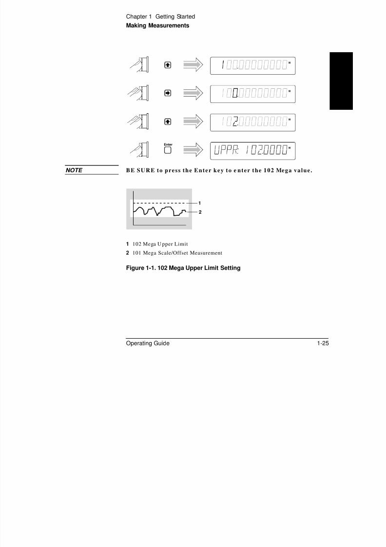
NOTE BE SURE to press the Enter key to e nter the 102 Mega value.
Figure 1-1. 102 Mega Upper Limit Setting
M
M
Enter
M
M
1 102 Mega U pper Limit
2 101 Mega Scale/Offset Measurement
1
2
Chapter 1 Getting Started
Making Measurements
Set t ing the Lower Limi t

8/4/2019 53131 Operating Guide
http://slidepdf.com/reader/full/53131-operating-guide 66/196
1-26 Operating Guide
1
Pr ess th e ar row keys as sh own in t he following steps t o set the lower limit
value.
Press the key six more times t o cau se th e Coun ter to display your entr y
in Mega un its a s sh own in th e following step.
NOTE BE SURE to press the Enter key to e nter the 100 Mega value.
Uppr &
Lower
M
M
M
EnterM
Chapter 1 Getting Started
Making Measurements
Limits should now be set as shown in Figure 1-2.

8/4/2019 53131 Operating Guide
http://slidepdf.com/reader/full/53131-operating-guide 67/196
Operating Guide 1-27
1
Figure 1-2. 100 Mega Lower and 102 Mega Upper Limits Settings
Figure 1-3 represents what t ran spired during this Math and Limits
procedure.
Figure 1-3. Math and Limits Results
1 102 Mega U pper Limit
2 101 Mega Scale/Offset Measurement
3 100 Mega Lower Limit
1 Raw Measurements
2 Math
3 Limits
4 Measurem ents (Scale/Offset Results)
within Limits
1
2
3
12 3 4
Chapter 1 Getting Started
Making Measurements
Set t ing the Counter to Flag a nd Stop Measur ing On

8/4/2019 53131 Operating Guide
http://slidepdf.com/reader/full/53131-operating-guide 68/196
1-28 Operating Guide
1
Out-of-Lim it Measur ement sIf you wan t t he Coun ter t o stop meas ur ing when th e signa l exceeds the
limits (102 to 100 Mega) that you en tered in th e previous procedure,
perform t he following st eps t o select th e STOP choice in th e ON FAIL
display. (Note tha t ON FAIL: GO ON is th e defau lt st at e after power-up.)
The curr ent m odified measur ement of th e input signal applied to
CHANNE L 2 is displayed.
Since the Count er is now in th e stop-on-fail mode, the Limit annunciator
in the display will light a nd t he Count er will stop making mea sur ement s
when a m easur ement exceeds the limits you set.
Limit
Modes
Run
Freq Ch 2
M
Gate
Chapter 1 Getting Started
Making Measurements
Set t ing th e Count er to Flag On Limi t s But Cont inu e
8/4/2019 53131 Operating Guide
http://slidepdf.com/reader/full/53131-operating-guide 69/196
Operating Guide 1-29
1
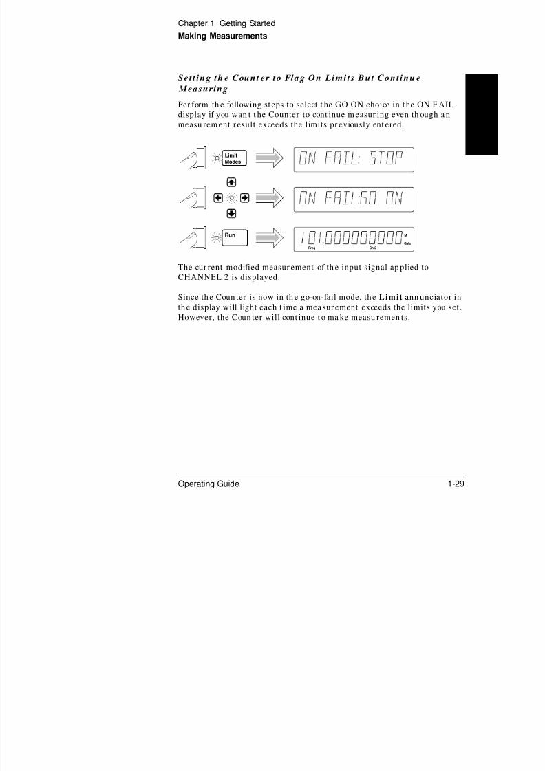
MeasuringPer form th e following st eps to select t he GO ON choice in t he ON F AIL
display if you wan t t he Counter to cont inue m easur ing even th ough a n
measu rem ent r esult exceeds the limits pr eviously ent ered.
The cur rent modified measur ement of th e input signal ap plied to
CHANNEL 2 is displayed.
Since th e Coun ter is now in th e go-on-fail mode, th e Limit ann unciator in
th e display will light each t ime a mea sur ement exceeds the limits you set.
However, the Coun ter will cont inue t o ma ke measu remen ts.
Limit
Modes
Run
Freq Ch 2
M
Gate
Chapter 1 Getting Started
Making Measurements
Disabl ing Lim i t Tes t ing

8/4/2019 53131 Operating Guide
http://slidepdf.com/reader/full/53131-operating-guide 70/196
1-30 Operating Guide
1
The Count er is now making measur ements without limit testing.
Disabl ing Math
The Coun ter is n ow ma king measu rem ents wit hout t he scale/offset values
calculated into th e measu rements.
Limit
Modes
Display 1, 7/13/92
Scale &
Offset
Display 1, 7/13/92
Run
Freq
MHz
Ch 2
Gate
Chapter 1 Getting Started
Making Measurements
To Perform Stat ist ics on Measu remen ts
S l t i th T f St t i t i (S t t )

8/4/2019 53131 Operating Guide
http://slidepdf.com/reader/full/53131-operating-guide 71/196
Operating Guide 1-31
1
Selec t ing th e Type of Sta t i s t i cs (Sta t s )
Suppose you wan t t he Count er to compu te a nd display the s tandard
deviat ion of the current input dat a (which is t he 10 MHz signal a pplied
to CHANNEL 2). Also, you want the Count er to make 20 measur ements
before it compu tes th e st an dar d deviation. Perform th e following steps.
Updat ing the SHOW configurat ion caused Sta ts t o be enabled. The Sta tsindicator is now lit.
NOTE BE SURE to press the Enter key to e nter the value of 20 .
Stats
Scale &
Offset
MATHStats
Stats
Enter
Chapter 1 Getting Started
Making Measurements
The Count er is now set to ma ke sta tist ics based on 20 measur ement s.

8/4/2019 53131 Operating Guide
http://slidepdf.com/reader/full/53131-operating-guide 72/196
1-32 Operating Guide
1
In t his case, th e displayed sta nda rd deviation value is compu ted on all
measu remen ts of th e 10 MHz signal since no limits were set.
Comp ut ing S ta t s on Fi l t ered Da ta Only
A special featu re of th e Coun ter allows you to use t he u pper a nd lower
limits to filter da ta before st at istical pr ocessing or compu ta tion as shown
in Figure 1-4.
Figure 1-4. Filtering Data Before Statistical Computation
1 Raw Measurements
2 Limits
3 Filtered data (USE: IN LIMIT)
4 Statistics
Run
Freq Ch 2
Hz
Freq Ch 2
Hz
Gate
Freq Ch 2
Gate
1 2 3 4
Chapter 1 Getting Started
Making Measurements
Per form th e following steps to select t he IN LI MIT choice in t he US E
display if you wa nt th e Coun ter to compu te st at istics on only frequ ency
measur ements within t he limits you set

8/4/2019 53131 Operating Guide
http://slidepdf.com/reader/full/53131-operating-guide 73/196
Operating Guide 1-33
1
measur ements within t he limits you set.
Since the Limits were set t o 101 Mega and 102 Mega values t ha t a re
based on a scale of 10 an d offset of 1 Mega, you m us t r e-ena ble Mat h n ow
to get t he mea sur ement s to be with in th e limits. Per form th e following
steps.
Display 1, 7/13/92
Display 1, 7/13/92
Stats
Display 1, 7/13/92
Scale &
Offset
Display 1, 7/13/92

8/4/2019 53131 Operating Guide
http://slidepdf.com/reader/full/53131-operating-guide 74/196
Chapter 1 Getting Started
Making Measurements
D i sab l ing S ta t s and Math
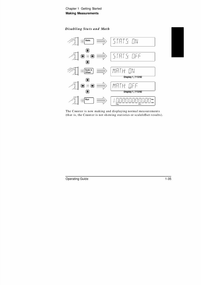
8/4/2019 53131 Operating Guide
http://slidepdf.com/reader/full/53131-operating-guide 75/196
Operating Guide 1-35
1
The Coun ter is now making and displaying norma l mea sur ement s
(th at is, the Count er is not sh owing stat istics or scale/offset r esults).
Stats
Display 1, 7/13/92
Scale &
Offset
Display 1, 7/13/92
Run
Freq
MHz
Ch 2
Gate
Chapter 1 Getting Started
Making Measurements
To Control Measu remen t
Use th ese two keys to cont rol the meas ur ement of the Coun ter.R Si l

8/4/2019 53131 Operating Guide
http://slidepdf.com/reader/full/53131-operating-guide 76/196
1-36 Operating Guide
1
yTh e Run key provides repetitive measu rem ents, whereas t he
Stop/Single key allows you t o ma ke one mea sur ement .
With th e 10 MHz signal st ill connected t o CHANNE L 2, perform th e
following steps so you can better un dersta nd t he Run an d Stop/Single
operations.
The Coun ter is n ow ma king repetitive measur ement s (cont inuously
making “live” measurements).
The Coun ter stopped ma king measur ements . The Gate an nun ciator is not
lit. Hence, pressing the Stop/Single key while the Counter is ma king
measu remen ts (in Run ) cau ses the Count er to stop after th e measur ement
in pr ogress is complet ed. If you pr ess t he Stop/Single key again while th e
Coun ter is stopped, the Count er will make a single measurem ent a nd th enstop—the Gate an nun ciator will light one time, momenta rily.
If you p ress t he Stop/Single key while the Counter is stopped an d when
the Stat s menu item ON SINGLE is set to N, the Counter will make
N measurement s and then stop. This enables a set of stat istics to be
computed.
While the Count er is still stopped, perform th e following step.
The Count er is m aking repetitive measur ements a gain.
Run Single/Stop
Run
Freq
MHz
Ch 2
Gate
Stop/
SingleFreq Ch 2
MHz
Run
Freq
MHz
Ch 2
Gate
2

8/4/2019 53131 Operating Guide
http://slidepdf.com/reader/full/53131-operating-guide 77/196
Opera t ing Your Un iversa l Counter
Oper at or ’s Referen ce
Chapter 2 Operating Your Universal Counter
Introduction
Introduction

8/4/2019 53131 Operating Guide
http://slidepdf.com/reader/full/53131-operating-guide 78/196
2-2 Operating Guide
2
IntroductionThis is t he operat or’s reference cha pter which cont ains inform at ion an d
procedures for th e front -pan el keys, operat ing functions, a nd menu s of th e
HP 53131A/132A 225 MHz Univer sal Count er.
Chapte r Sum mary
• How th is Counter Works for You page 2-4
• Using the Measurement Contr ol Keys (Run and
Stop/Single)
page 2-5
• Using Ent ry/Select (Arrow) Keys page 2-8
• Using the MEASURE Menu Keys page 2-10
• Using the Ga te & Externa l Arm Menu Key page 2-16
• Using the MATH Menu Keys page 2-27
• Using the LIMITS Menu Keys page 2-37
• Using CHANNE L 1 an d CHANNEL 2 Input
Conditioning Keys
page 2-44
• Using t he Save and Recall Menus page 2-52
• Using the Pr in t Menu page 2-56
• Using the Ut ility Menu page 2-57
• Using t he Ca libra t ion Menu page 2-67
• Front Panel Display Messages page 2-73
• Preset Values After Power-Up and *RST page 2-78
• Summary of the Measurement Sequence page 2-93• Common Quest ions page 2-94
Chapter 2 Operating Your Universal Counter
Introduction
Whe re to Fin d Som e Key Working Exam ples
• Example Procedure for Ga te and External Arm page 2-24
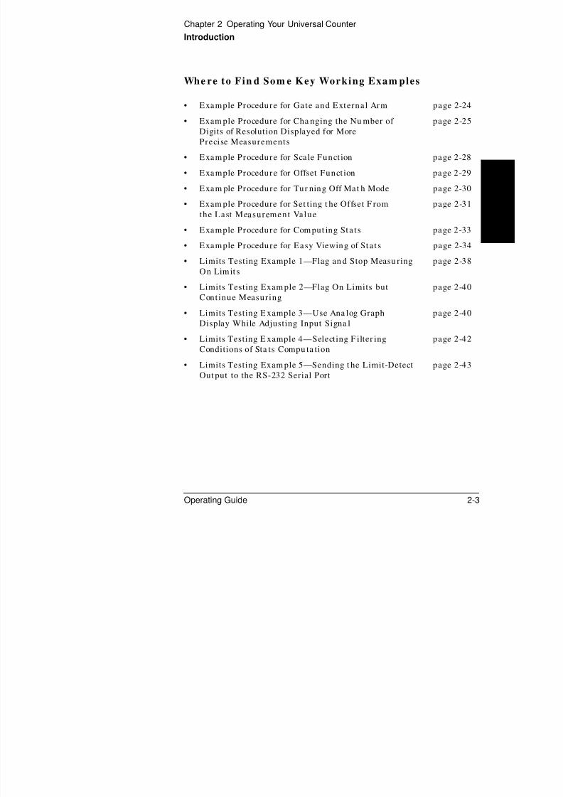
8/4/2019 53131 Operating Guide
http://slidepdf.com/reader/full/53131-operating-guide 79/196
Operating Guide 2-3
2
p p g
• Exam ple Procedure for Cha nging the Nu mber of
Digits of Resolution Displayed for More
Precise Measurements
page 2-25
• Example Procedure for Scale Funct ion page 2-28
• Example Procedure for Offset Funct ion page 2-29
• Exam ple Procedure for Tur ning Off Mat h Mode page 2-30
• Exam ple Procedure for Set ting t he Offset F rom
the Last Measurement Value
page 2-31
• Example Procedure for Com put ing Sta ts page 2-33
• Example Procedure for Easy Viewing of Sta t s page 2-34
• Limits Testing Example 1—Flag an d Stop Measu ringOn Limit s
page 2-38
• Limits Testing Exam ple 2—Flag On Limits but
Continue Measuring
page 2-40
• Limits Testing E xample 3—Use Ana log Graph
Display While Adjusting Input Signa l
page 2-40
• Limits Testing E xample 4—Selecting F ilter ing
Conditions of Sta ts Compu ta tion
page 2-42
• Limits Testing Exam ple 5—Sending t he Limit-Detect
Out put to the RS-232 Serial Port
page 2-43
Chapter 2 Operating Your Universal Counter
How this Counter Works for You
How th is Counter Works for You
8/4/2019 53131 Operating Guide
http://slidepdf.com/reader/full/53131-operating-guide 80/196
2-4 Operating Guide
2
The following text lists some of th e key th ings t he Count er d oes for you.
• The Counter presets the menus to defaul t sta tes and values a t
power-up (refer t o Table 2-7A for a d eta iled list of th e preset va lues).
Cycling th e POWER key presets th e Coun ter.
• The Counter’s Utili ty menu a llows you to select such things as
tim ebase sour ce, HP -IB configur at ion, an d RS-232 serial port
configuration. After your selections, the Counter automatically stores
all th ese selections in non-volatile memory (except the t imebase
source ); th us, th ese sett ings (except t imeba se sour ce) will n ot change
when power ha s been off or a fter a remote int erface reset.
• The Counter aut omatically displays measurement(s) in a couple of
seconds a fter you select a mea sur emen t fun ction (e.g., Per iod).
• The Counter accepts your numeric entry for a menu i tem after you
press the Enter key. You MU S T press the En ter key to com plete
nu m eric entry.
• The Counter automatically enables Limits when you enter a numeric
value for u pper an d/or lower limits, or u pdat e any men u item in th e
Limit Modes menu .
• The Counter automatically enables Math after you enter a numericvalue for scale an d offset.
• The Counter performs Statis t ical analyses for you, and will enable
Stat s when you updat e any item in the Stats m enu.
• The Counter automatically disables Limits , Math, and Stats when you
select another mea sur ement function.
• The Coun ter s aves measurement s etup(s ).
• The Counter ins tant ly recal ls the measurement se tup you want to use .
• The Counter pr in ts out your measurement and analys is data .
Chapter 2 Operating Your Universal Counter
Using the Measurement Control Keys (Run and Stop/Single)
Using the Measu rement Cont rol Keys(Run an d Stop/Single)

8/4/2019 53131 Operating Guide
http://slidepdf.com/reader/full/53131-operating-guide 81/196
Operating Guide 2-5
2
(Run an d Stop/Single)
Overview of the Measurem ent Control Keys
Two mea sur ement cont rol keys a re pr ovided on t he H P 53131A/132A
Counter: Run and Stop/Single . In genera l, th e Run key pr ovides
repetitive measurement s while the Stop/Single key allows you to mak e
single-shot measurements.
Th e Run key a llows you t o:
• put the Counter in to a cont inuous measurement loop.
• exit any measurement after your selection of another measurement
function.
• abor t the cur rent measurement by s tar t ing a new measurement
(if alrea dy in Run m ode or in Single mode with a mea sur ement in
progress). This a lso clear s an y sta tist ics being processed.
Th e Stop/Single key a llows you t o:
• put the Counter into Single mode (if the Counter was in Run mode)
where one measur ement is tak en with each Stop/ Single keypress.
(Stat s menu item ON SINGLE should be set t o 1.)
• put the Counter into Single mode (if the Counter was in Run mode)
where N measur ements ar e taken with each Stop/ Single keypress.
(Stat s menu item ON SINGLE should be set t o N .)
• s top (abort) the current measurement (if the Counter was in Single
mode).
Run Stop/
Single
Chapter 2 Operating Your Universal Counter
Using the Measurement Control Keys (Run and Stop/Single)
To Use the Measu remen t Control Keys
The following procedure demonstrates how these keys function.
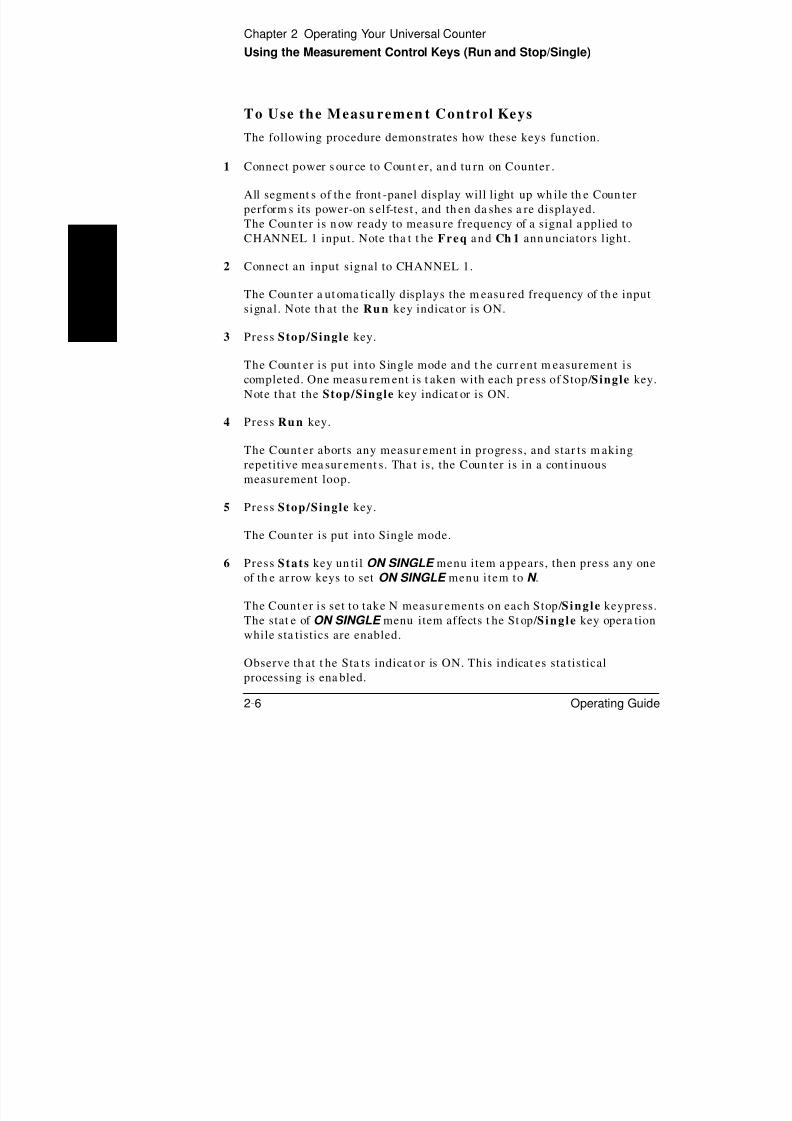
8/4/2019 53131 Operating Guide
http://slidepdf.com/reader/full/53131-operating-guide 82/196
2-6 Operating Guide
2
1 Connect power s our ce to Count er, an d tu rn on Counter .
All segment s of th e front -panel display will light up wh ile th e Coun ter
perform s its power-on s elf-test , and th en da shes a re displayed.
The Coun ter is n ow ready to measu re frequency of a signal a pplied to
CHANNEL 1 input. Note tha t t he Freq and Ch 1 ann unciators light.
2 Connect an input signal to CHANNEL 1.
The Coun ter a ut oma tically displays the m easu red frequency of th e input
signal. Note th at the Ru n key indicat or is ON.
3 Press Stop/Single key.
The Count er is put into Single mode and t he curr ent m easurement iscompleted. One measu rem ent is t aken with each pr ess of Stop/ Single key.
Note that the Stop/Single key indicat or is ON.
4 Press Run key.
The Count er aborts any measur ement in progress, and star ts m aking
repetitive mea sur ement s. Tha t is, the Coun ter is in a cont inuous
measurement loop.
5 Press Stop/Single key.
The Coun ter is put into Single mode.
6 Press Stats key un til ON SINGLE menu item a ppears, then press any one
of th e ar row keys to set ON SINGLE menu i tem to N .
The Count er is set to take N measur ements on each Stop/ Single keypress.
The stat e of ON SINGLE menu item affects t he St op/ Single key opera tion
while sta tistics are enabled.
Observe th at t he Sta ts indicat or is ON. This indicat es sta tistical
processing is ena bled.
Chapter 2 Operating Your Universal Counter
Using the Measurement Control Keys (Run and Stop/Single)
7 Press Stop/Single key.
One set of N frequen cy measur ement s is taken with each press of th eStop/ Single key. One set of sta tistics is compu ted with each press of the

8/4/2019 53131 Operating Guide
http://slidepdf.com/reader/full/53131-operating-guide 83/196
Operating Guide 2-7
2
p g y p p
Stop/ Single key.
8 Press Stats key until SHOW menu item appears.
9 Pr ess an y one of th e ar row keys to select a sta tistical result t o display, and
press Enter key.
The Coun ter is now displaying one of th e sta tist ical r esults.
10 Press Stop/Single key.
One set of N frequen cy measur ement s is taken with each press of th e
Stop/ Single key. At t he completion of th e Nth measu remen t, th e Count er
displays t he st at istical resu lt selected in st ep 9.
11 Press Stats key un til ON SINGLE menu item a ppears, then press any one
of th e ar row keys to set ON SINGLE menu item to 1.
The Coun ter is set to take one mea sur ement on each Stop/ Single
keypress.
Disabling the st at istics (with t he STATS: OFF menu item) is another way
to cau se th e Stop/ Single key to initiate one measurement at time.
Chapter 2 Operating Your Universal Counter
Using Entry/Select (Arrow) Keys
Using En t ry/Select (Arrow) KeysTh i t / l t k f hi h f “ ” k

8/4/2019 53131 Operating Guide
http://slidepdf.com/reader/full/53131-operating-guide 84/196
2-8 Operating Guide
2
Ther e ar e six entr y/select k eys of which four ar e “ar row” keys.
The fun ction of th e four a rrow keys and th e Ent er key depends on th e
Count er’s opera ting m ode (th at is, numer ic entr y, sta te chan ging,
sequen cing t hr ough choices in a men u, et c.). This section describes how
th e keys perform in t he different operat ing modes.
To Use During Nu meric Entry
• Use the key to move left t o select adjust able digits (it does not wr ap
around).
• Use the key to move right to select a djust able digits (it does not wra p
around).
• Use the key to increm ent th e selected (highlighted ) digit of th e
displayed value.• Use the key to decrem ent th e selected (highlight ed) digit of th e
displayed value.
• Use the +/ − key to cha nge th e sign of the n umer ic value.
• Use the Enter key to complete a nu meric entr y. (If a nu meric entr y is
chan ged and th e Enter key is NOT pressed, th en t he value is not
changed.)
To Use When Sequencing Through the Measuremen t
Fun ction Menu s (Freq & Ratio, Time & Perio d, Other
Meas) and th e Reca l l Menu
• Use the or key t o go back t o the p revious choice in a fun ction or
recall men u. Repeat edly pressing t his k ey will cycle th rough (an d loop
ar ound) t he list of choices.
• Use the or key t o go forwar d or t o the next choice in a fun ction or
recall menu. Repeatedly pressing this key will cycle th rough (and loop
ar ound) t he list of choices.
• Use the Enter key to select t he function or execut e th e recall, or wait
for t he m enu to time out for a ut omat ic selection/execution.
Enter+/ –
Chapter 2 Operating Your Universal Counter
Using Entry/Select (Arrow) Keys
To Use D urin g Sta te Cha ng ing (ON/OFF, LO/MED/HI,
etc.)
• Press any of the a rr ow keys to toggle or chan ge to the n ext sta te of the
f d i h f ll i

8/4/2019 53131 Operating Guide
http://slidepdf.com/reader/full/53131-operating-guide 85/196
Operating Guide 2-9
2
par am eters foun d in th e following menus:
– Gate & ExtArm
– Limit Modes
– Sca le & Offset
– Sta ts– Tr igger /S en sit ivit y
– 50Ω /1MΩ
– DC/AC
– X10 At tenuat e
– 100kH z Filt er
– Save & Pr in t– Utility Men u
• The Enter and +/ − keys are ignored during the sta te changing
operat ing mode.
To Use on Promp ted Even t Messa ges (SET OFFSET ?,
CAL: OFFS n ?, TES T: ALL?, e tc .)
• For SET OFFSET ? , and all the TEST: ? prompted event messages,
press Enter key to start the event.
• For CAL: OFFS n ? and GAIN n ? , press Enter key to display
instr uctions. Press Enter key again to start the event.
To Use on Promp ted He lp Messa ges (MATH HELP ?,
P RINT HELP ?)
• When MATH HELP ? is displayed, press Enter key to display t he
“(MEAS x SCALE) + OFFS = RESULT ” mess age.
• When PRINT HELP ? is displayed, press Enter key to display t he
“CONFIGURE PORT ON UTILITY MENU; REMEMBER TO SAVE
SETUP FIRST ” instruction.
Chapter 2 Operating Your Universal Counter
Using the MEASURE Menu Keys
Using th e MEASURE Menu KeysOverview of the MEASURE Menus

8/4/2019 53131 Operating Guide
http://slidepdf.com/reader/full/53131-operating-guide 86/196
2-10 Operating Guide
2
Overview of the MEASURE Menus
The measu remen t function men us a re divided into three categories:
• Frequency measurements on channel 1, 2, or 3 (optional) and rat io of
frequencies between cha nn els.
• Time interval, period, and pulse characterization measurements .(The HP 53131A/132A provides one k ey-press opera tion for su ch pulse
measu remen ts a s risetime, falltime, pulse width, etc., which h ave
tr aditionally required mult iple key presses or operat ions.)
• Other measurements (dutycycle, phase, peak voltage, and totalize).
To sequence through t he m enus of th e MEASUREm ent fun ction k eys
(Freq & Ratio , Time & Pe riod , and Other Meas keys), you simply n eed
to repeatedly press th e appr opriat e MEASURE key to cycle thr ough (and
loop ar oun d) the menu s un der t he key. Each pr ess of a MEASURE key
will advance th e Count er to the next measu remen t function in th e menu.
NOTE The menu s und er th e MEASURE keys will ter mina te (select function a ndretu rn t o measu remen t r esult display) after t wo seconds.
Table 2-1. Menus of the MEASUREment Keys
F re q & R at io Ke y Ti me & P e r io d Ke y Ot he r Me a s Ke y
FREQUE NCY 1
REQUENCY 2
REQUE NCY 3 (optional)
ATIO 1 TO 2
ATIO 1 TO 3 (optional)
ATIO 2 TO 1
RATIO 3 TO 1 (optional)
TI 1 TO 2
PERIOD 1
RISETIME 1
FALLTIME 1
POS WIDTH 1
NEG WIDTH 1
TOTALIZE 1
PH ASE 1 TO 2
DUTYCYCLE 1
VOLT PEAKS 1
VOLT PEAKS 2
Other
Meas
Time &
Period
Gate &
ExtArm
MEASURE
Freq &
Ratio
Chapter 2 Operating Your Universal Counter
Using the MEASURE Menu Keys
To Measure Frequency
1 Connect power source to Coun ter, a nd t ur n on Count er.
All segment s of th e front -panel display will light up wh ile the Count er
8/4/2019 53131 Operating Guide
http://slidepdf.com/reader/full/53131-operating-guide 87/196
Operating Guide 2-11
2
g pa p ay w g p w
perform s its power-on self-test , and th en da shes a re displayed.
The Coun ter is now ready to meas ur e frequency of a signal applied to
CHANNEL 1 input. Note th at the Freq and Ch 1 ann unciat ors light.
2 Connect a n inpu t signal t o CHANNEL 1.
The Coun ter should au tomat ically display th e meas ur ed frequency of the
input signal. The tr igger levels are set t o the 50% points of the signa l.
However, you m ay disa ble aut o triggering, and cha nge th e t rigger levels
and slopes.
To set u p CHANN EL 1’s couplin g, impeda nce, and t riggering condit ions t o
ma tch th e input signal you ar e trying to measu re, refer to the procedur es
“To Select In put Coupling an d Impeda nce” an d “To Set Input Cha nnelTrigger Level/Sensit ivity” in Cha pter 1, “Getting Star ted,” or t he section
titled “Using CHANNE L 1 an d CHANNE L 2 Inpu t Conditioning Keys” in
this chapt er.
3 Press the Freq/Ratio key unt il FREQUENCY 2 is displayed to measu re
th e frequency of an inpu t signal a pplied to CHANNEL 2.
FREQUENCY 2 is momenta rily displayed, th e Freq and Ch 2 an nu nciat ors light, and t he Coun ter is r eady to measur e frequency of a
signa l applied to CHANNEL 2 inpu t. The t rigger levels are set to the
50% points of the signal. However, you m ay disable au to triggering, an d
cha nge t he t rigger levels a nd slopes.
4 To mea sur e th e frequ ency of a signa l applied to opt iona l CHANNE L 3
input, repeat step 3 until FREQUENCY 3 is displayed.
FREQUENCY 3 will be moment ar ily displayed an d th e Freq and Ch 3
an nu nciat ors will light . The Coun ter will be ready to measu re t he
frequency of a signa l applied to CHANNE L 3 inpu t.
Note t hat the F requency 3 menu item is not available in Count ers tha t do
not cont ain optiona l Chan nel 3.
Chapter 2 Operating Your Universal Counter
Using the MEASURE Menu Keys
To Measu re Frequen cy Ratio
1 Press Fre q & Ratio key until RATIO 1 TO 2 is displayed.
RATIO 1 TO 2 is momenta rily displayed, th e Freq , Ch 1, and Ch 2
8/4/2019 53131 Operating Guide
http://slidepdf.com/reader/full/53131-operating-guide 88/196
2-12 Operating Guide
2
y p y , q , ,
ann unciat ors light, an d th e Count er is ready to measure an d display the
frequency rat io of a signal a pplied to CHANNEL 1 in relat ion t o a signal
app lied to CHANNE L 2 (Ch1/Ch2). The t rigger levels ar e set t o th e
50% points of each signal. However, you ma y disable au to tr iggering, and
cha nge th e tr igger levels an d slopes.
Note the result is not scaled by 100; it is not a percent age.
Note t ha t RATIO 2 TO 1 is also ava ilable (Ch2/Ch1).
2 To meas ur e th e frequency rat io between a signal applied to CHANNE L 1
input and a signa l applied to Option 030/050 CHANNE L 3 input, repea t
st ep 1, above.
RATIO 1 TO 3 will be moment ar ily displayed an d th e Freq , Ch 1, and
Ch 3 an nu nciat ors will light . The Count er will be ready to measur e th e
frequency rat io of a signal a pplied to CHANNEL 1 in relat ion t o a signal
applied t o CHANN EL 3 (Ch1/Ch3).
Note that th e Ratio 1 to 3 menu item is not available in Count ers th at do
not cont ain optiona l Chan nel 3.
Note the result is not scaled by 100; it is not a percent age.
Note t ha t RATIO 3 TO 1 is also ava ilable (Ch3/Ch1).
By pressing th e Fre q & Ratio key, th e Coun ter will retu rn t o th e
Fr equency 1 measu remen t mode; th is demonstr at es the loop around
featu re of th e measu remen t function men u keys.
The front -pa nel “ar row” (or en tr y/select) keys can also be used when
sequencing thr ough t he measu rem ent function men us. Refer to the
section t itled “Using E nt ry/Select (Arr ow) Keys” for d eta ils.

8/4/2019 53131 Operating Guide
http://slidepdf.com/reader/full/53131-operating-guide 89/196
Chapter 2 Operating Your Universal Counter
Using the MEASURE Menu Keys
To Measu re Po sit ive/Nega t ive P ulse Widths
Press Time & Period key unt il POS WIDTH 1 or NEG WIDTH 1,depending on which meas urem ent you want to make, is displayed.

8/4/2019 53131 Operating Guide
http://slidepdf.com/reader/full/53131-operating-guide 90/196
2-14 Operating Guide
2
POS WIDTH 1 or NEG WIDTH 1 is momenta rily displayed, and th e +Wid
or −Wid , and Ch 1 ann unicators light. The pulse width measur ement
au toma tically configures th e Coun ter t o perform p ositive or nega tive pulse
width m easurements thr ough CHANNEL 1 input. The AUTO TRIG is set
to trigger at th e 50% point of th e signal.
To Measu re Du ty Cycle
Press Other Meas key until DUTYCYCLE 1 is displayed.
DUTYCYCLE 1 is momenta rily displayed, th e Ch 1 annunciator lights.
The du tycycle mode of operat ion is rea dy to mea sur e a cont inu ous
waveform applied to CHANNE L 1 input. The input is aut oma tically set to
comm on-chan nel 1, an d tr iggerin g set t o AUTO TRIG: ON. The t riggerlevels a re set to th e 50% points of each signa l. However, you m ay disa ble
aut o triggering, and change t he t rigger levels.
Result s will ran ge from 0 to 1. The du tycycle is defined a s th e positive
pulse width divided by the period. (Note tha t t he r esult is n ot scaled
by 100; it is not a percent age.)
To Make Totalize Measureme ntsPress Other Meas key until TOTALIZE 1 is displayed.
TOTALIZE 1 is momenta rily displayed, the Ch 1 annunciator lights,
and the Counter is in its t ota lize mode. Aut o-tr iggering is au tomat ically
disabled on CHANNEL 1 since there m ay not be a suita ble signal at th e
beginning of th e mea sur ement . The t ota lize mode of opera tion displays
th e nu mber of coun ts (event s) received th rough CHANNEL 1. The count is
contin uously displa yed if GATE: AUTO is s elected.
The tota lize measu remen t is clear ed to zero when t he t ota lize function is
first invoked, when th e front -pan el Run key is pressed, or when th e
Stop/ Single key is pressed.
Chapter 2 Operating Your Universal Counter
Using the MEASURE Menu Keys
To Make Phase Measuremen ts
Press Other Meas key until PHASE 1 TO 2 is displayed.
PHASE 1 TO 2 is momenta rily displayed, th e Ch 1 and Ch 2 annunicators
li h d h C i d h h f i l li d

8/4/2019 53131 Operating Guide
http://slidepdf.com/reader/full/53131-operating-guide 91/196
Operating Guide 2-15
2
light, and t he Count er is ready to measur e the ph ase of a signal applied to
CHANNEL 1 input relative to a signal applied to CHANNEL 2 input .
The pha se difference is displayed in degrees. If au to tr iggering is ena bled,
th e tr igger levels ar e set t o th e 50% point s of each signa l. However, you
ma y disable auto tr iggering, an d change th e tr igger levels and slopes.
Use CHANNE L 2 as th e reference. One period on CHANNEL 2 will
define 360°. If CHANNEL 1 is leading CHANNEL 2, the pu lse result is
positive.
To Measu re Posit ive/Negat ive Voltage P eaks
Press Other Meas key until VOLT PEAKS 1 or VOLT PEAKS 2 ,
depending on which measu remen t you wan t t o ma ke, is displayed.
VOLT PEAKS 1 or VOLT PEAKS 2 is momenta rily displayed, the Ch 1 or
Ch 2 ann unciator lights, an d th e Count er is ready to measure minimum
an d ma ximu m volta ge peaks of signa ls applied to CHANNE L 1 or
CHANNE L 2, respectively.
NOTE In Voltage Peaks function, the Counter m easu res th e input signal after
th e signa l has been conditioned by th e input sett ings (impedance,coupling, att enua tion, and filter ). One rem inder of th is is the
(AC COUPLED ) messa ge, which is displayed when Volta ge Peak s is
selected an d th e measu remen t chan nel is ac coupled.
The resu lt is corrected for X10 at tenu at ion.
Note tha t Arming is not used for Voltage Peaks mea sur ement s, and th atneither Limits nor Math is available.
Chapter 2 Operating Your Universal Counter
Using the Gate & External Arm Menu Key
Using th e Gate & Extern al Arm Menu Key
Overview of Gate/External Arming Fun ct ions
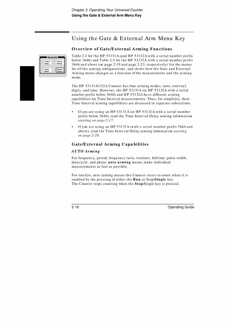
8/4/2019 53131 Operating Guide
http://slidepdf.com/reader/full/53131-operating-guide 92/196
2-16 Operating Guide
2
Table 2-2 for t he HP 53131A (and H P 53132A with a serial number prefix
below 3646) and Table 2-3 for t he HP 53132A with a serial nu mber pr efix
3646 an d a bove (on page 2-19 and page 2-23, respectively) list the menus
for a ll th e arm ing configura tions, and sh ows how th e Gate a nd Exter na l
Arming menu chan ges as a function of the m easurement and t he ar ming
mode.
The HP 53131A/132A Coun ter ha s four ar ming m odes: auto, exter na l,
digits, and time. However, the HP 53131A (or HP 53132A with a serial
num ber prefix below 3646) and H P 53132A ha ve different ar ming
capa bilities for Time Int erval m easu remen ts. Thu s, for simplicity, their
Time Interval ar ming capa bilities are discussed in separ at e subsections.
• I f you are us ing an HP 53131A (or HP 53132A with a ser ia l number
prefix below 3646), read t he Time In ter val Delay arm ing inform at ion
starting on page 2-17 .
• If you are using an HP 53132A (with a serial number prefix 3646 and
above), read t he Time In ter val Delay arm ing inform at ion starting
on page 2-20.
Gate/Exte rnal Arming Capa bilit ies
AUTO Armi ng
For frequen cy, period, frequ ency rat io, risetim e, fallt ime, pulse width ,
dutycycle, and phase, auto arming means make individual
measu remen ts as fast as possible.
For tota lize, au to arming mea ns th e Count er sta rt s to coun t when it is
enabled by the pr essing of either th e Run or Stop/ Single key.
The Count er stops count ing when th e Stop /Single key is press ed.
Other
Meas
Time &
Period
Gate &
ExtArm
MEASURE
Freq &
Ratio
Chapter 2 Operating Your Universal Counter
Using the Gate & External Arm Menu Key
EXTERN AL Arm ing
For frequen cy, period, frequ ency rat io, and t otalize, external arming means you can contr ol the sta rt of a measurement by using an externa l
signal.

8/4/2019 53131 Operating Guide
http://slidepdf.com/reader/full/53131-operating-guide 93/196
Operating Guide 2-17
2
NOTE When externa l arm ing mode is enabled, a signa l must be connected to the
Count er’s rear -pan el Ext Arm connector.
TIME Armi ngFor frequen cy, period, rat io, and t otalize, t ime arming mean s you can set
th e gate t ime—th e length of time for wh ich your signal is mea sur ed.
NOTE Gate t ime and r esolution are linked: th e longer th e gate time, the great er
th e resolut ion. With a n increase in r esolution, you get a larger n um ber of
digits on t he displa y.
Time arm ing is demonstra ted in t he sub-section titled “Example
Procedure for Gat e and E xtern al Arm .”
DIGITS Arm ing
For frequen cy, period, and r at io, digits arming means you can set t he
nu mber of digits of resolut ion th at you require your result to provide.
Digits ar ming is demonstra ted in t he su b-section t itled “Example
Procedure for Chan ging th e Nu mber of Digits of Resolution Displayed for
More Precise Measur ements.”
HP 53131A (an d HP 53132A With S/N Pr efix Below 3646)
Time Interval DELAY Arm ing
The DE LAY capa bility (specified in t he Time Int erval a rm ing menu )
provides a var iable delay between th e star t event (Chann el 1) an d the
ena bling of th e stop event (Chan nel 2) as sh own Figure 2-1. Potential st op
event s ar e ignored du ring th e specified delay t ime.
Extern al ar ming can a lso be used to cont rol th e star t of a m easur ement by
using an externa l signal.
Chapter 2 Operating Your Universal Counter
Using the Gate & External Arm Menu Key
NOTE When externa l arm ing mode is enabled, a signal mu st be conn ected t o th e
Count er’s rea r-panel Ext Arm connector.
DESIRED T I MEASUREMENT
START STOP

8/4/2019 53131 Operating Guide
http://slidepdf.com/reader/full/53131-operating-guide 94/196
2-18 Operating Guide
2
Figure 2-1. HP 53131A (HP 53132A S/N Prefix Below 3646) Time Interval
Delay
NOTE The examples in Figure 2-1 have the input signal applied to Channel 1
with COMMON 1: ON, Chan nel 1 SLOPE: POS, and Channel 2 SLOPE:
POS.
DESIRED T.I. MEASUREMENTACTUAL T.I. MEAS
ARM: AUTO, DELAY: NONE
DESIRED T.I. MEASUREMENT
START STOP
ACTUAL T.I. MEASDELAY TIME
ARM: AUTO, DELAY: TIME, TIME: (specified)
(standard T.I. measurement)
DESIRED T.I. MEASUREMENT
START STOP
ACTUAL T.I. MEAS
ARM: EXTERNL, SLOPE: POS, DELAY: TIME, TIME: (specified)
DELAY TIME
EXT ARM INPUT
Chapter 2 Operating Your Universal Counter
Using the Gate & External Arm Menu Key
Table 2-2. *HP 53131A (HP 53132A S/N Prefix Below 3646) Gate & External Arm Key Menus as
a Function of the Measurement and Arming Mode
Freq, Period,
Ratio
Phase Totalize RiseTime, Fall Time,
+/−Width, Dutycycle
Time Interval

8/4/2019 53131 Operating Guide
http://slidepdf.com/reader/full/53131-operating-guide 95/196
Operating Guide 2-19
2
, y y
Auto Arming:
GATE: AUTO
Auto Arming:
ARM: AUTO
Auto Arming:
GATE: AUTO
Auto Arming:
ARM: AUTO
Auto Arming:
ARM: AUTO
DELAY: NONE
TIME
TIME: <time>
Digits Arming:
GATE: DIGITS
DIGITS: <digits> _______________ _______________ _______________ _______________
Time Arming:
GATE: TIME
TIME: <time>
_______________
Time Arming:
GATE: TIME
TIME: <time>
_______________ _______________
External Arming:
GATE: EXTERNL
START: POS
NEG
STOP: AUTO
NEG
POS
TIME
TIME: <time>
External Arming:
ARM: EXTERNL
SLOPE: POS
NEG
External Arming:
GATE: EXTERNL
START: POS
NEG
STOP: NEG
POS
TIME
TIME: <time>
External Arming:
ARM: EXTERNL
SLOPE: POS
NEG
External Arming:
ARM: EXTERNL
SLOPE: POS
NEG
DELAY: NONE
TIME
TIME: <time>
* There is no Gate and External Arm menu available for Voltage Peaks measurements.
Chapter 2 Operating Your Universal Counter
Using the Gate & External Arm Menu Key
HP 53132A (With S /N Pr efix 3646 a nd Above) Tim e Int erva l
DELAY Arm ing
In t he following subsections, a leadin g sta r (G) means t he para meter
affects t he START event . A tr ailing star mean s th e par am eter a ffects
STOP event .

8/4/2019 53131 Operating Guide
http://slidepdf.com/reader/full/53131-operating-guide 96/196
2-20 Operating Guide
2
AUTO ARMING (GSTART: AUTO)
The DELAYG (stop delay) capability (specified in t he Tim e Int erval
arm ing menu) provides a variable delay between th e star t event
(Chann el 1) and t he enabling of the stop event (Channel 2) as sh own inFigure 2-2. Two types of delay a re possible: 1) TIME—pot ent ial st op
event s ar e ignored during t he specified delay t ime, or 2) EVENT—
th e mea surem ent is stopped when the specified nu mber of stop event s has
occurred.
EXTERNAL ARMING (GSTART: EXT)
Extern al ar ming can be used to cont rol th e star t, or st ar t a nd st op, of ameasu remen t by using an extern al signa l as shown in Figure 2-3.
Set STOPG and/or GSTART to EXT to activat e.
NOTE When externa l arm ing mode is enabled, a signal mu st be conn ected t o th e
Count er’s rea r-panel Ext Arm connector.
Th e GDELAY (sta rt delay) cap ability (specified when GSTART is set t o
EXT) provides a variable delay between th e ar ming event (Ext Arm) an d
th e enabling of the sta rt of the mea sur ement . Two types of delay are
possible: 1) TIME—poten tial sta rt events (Cha nnel 1) ar e ignored during
th e specified delay time, or 2) EVENT—th e measur ement is sta rt ed after
th e specified number of Chan nel 2 events h as occur red. A DELAYG
(stop delay) as described in AUTO ARMING above can a lso be used in
conjun ction with GDELAY (sta rt delay) as sh own in Figure 2-3.
Chapter 2 Operating Your Universal Counter
Using the Gate & External Arm Menu Key
DESIRED T.I. MEASUREMENT
START STOP
ACTUAL T.I. MEAS

8/4/2019 53131 Operating Guide
http://slidepdf.com/reader/full/53131-operating-guide 97/196
Operating Guide 2-21
2
Figure 2-2. HP 53132A (With S/N Prefix 3646 and Above) Auto Arming
NOTE The examples in Figure 2-2 have the input signal applied to Channel 1
with COMMON 1: ON, Channel 1 SLOPE: POS, and Channel 2 SLOPE:
POS.
START: AUTO, DELAY : NONE
DESIRED T.I. MEASUREMENT
START STOP
ACTUAL T.I. MEASDELAY TIME
DESIRED T.I. MEASUREMENT
START STOP
ACTUAL T.I. MEASDELAY STOP TO 4th EVENT
1 2 3 4
START: AUTO, DELAY : TIME, T : (specified)
START: AUTO, DELAY : EVENT, E : 4
(standard T.I. measurement)
Chapter 2 Operating Your Universal Counter
Using the Gate & External Arm Menu Key
DESIRED T.I. MEASUREMENT
START STOP
ACTUAL T.I. MEASDELAY STOP TO 4th EVENT
START DELAY TIME
EXT ARM INPUT

8/4/2019 53131 Operating Guide
http://slidepdf.com/reader/full/53131-operating-guide 98/196
2-22 Operating Guide
2
Figure 2-3. HP 53132A (With S/N Prefix 3646 and Above) External Arming
NOTE The examples in Figure 2-3 have the input signal applied to Channel 1
with COMMON 1: ON, Channel 1 SLOPE: POS, and Channel 2
SLOPE: NEG. Thus, the signals applied to Channel 1 and Channel 2 are
ident ical, however, the cha nn el events occur on opposite slopes.
START: EXT, SLOPE: POS, DELAY: TIME, T: (specified), STOP : AUTO, DELAY : EVENT, E : 5
2 3 4 5
DESIRED T.I. MEASUREMENT
START STOP
ACTUAL T.I. MEAS
2 3 4
DELAY START BY 4 CHAN 2 EVENTS
EXT ARM INPUT
1
5
START: EXT, SLOPE: POS, DELAY: EVENT, E: 5, STOP : EXT, SLOPE : NEG, DELAY : NONE
1

8/4/2019 53131 Operating Guide
http://slidepdf.com/reader/full/53131-operating-guide 99/196
Chapter 2 Operating Your Universal Counter
Using the Gate & External Arm Menu Key
To Use the Gate and Exte rnal Arm
Exa mp le Procedu re for Gate and Externa l ArmFor demonst ra tion purposes, you wa nt t o set up t he Coun ter so tha t it
uses an external arm to start a measu rement. You want to make a
Tota lize measu remen t on th e positive edges (th at is, count th e num ber of

8/4/2019 53131 Operating Guide
http://slidepdf.com/reader/full/53131-operating-guide 100/196
2-24 Operating Guide
2
p g (
positive edges) of a pu lse-tr ain signa l app lied to cha nn el 1. Also, you wa nt
to perform t he mea sur ement dur ing an interva l of 5 milliseconds as sh own
in t he following figure.
Per form th e following procedur e to accomplish th is ta sk.
1 Turn on th e Count er, and press Stop/Single to put th e Count er into the
single measurement mode.
2 Connect th e pulse-tr ain signal to cha nnel 1 input, an d press Oth er Meas
key unt il TOTALIZE 1 is displayed.
3 Connect a n extern al TTL signa l to the Counter ’s rear -pan el Ext Arm
connector.
4 Press Gate & ExtArm key.
GATE: TIME is displayed.
5 Press a ny one of th e arr ow keys unt il GATE: EXTERNL is displayed.
6 Press Gate & ExtArm key.
START: POS is displayed. (If START: NEG is displayed instead, t hen
press a ny one of th e ar row keys to toggle to th e next st at e—POS ).
Gate
ExtArm
CHANNEL 1
5 ms
ExtArm
Chapter 2 Operating Your Universal Counter
Using the Gate & External Arm Menu Key
7 Press Gate & ExtArm key.
STOP: NEG is displayed.
8 Pr ess an y one of th e ar row keys un til STOP: TIME is displayed.
9 S h G Ti 5 b f i h f ll i

8/4/2019 53131 Operating Guide
http://slidepdf.com/reader/full/53131-operating-guide 101/196
Operating Guide 2-25
2
9 Set t he Ga te Time t o 5 ms by perform ing the following steps:
a. Press Gate & ExtArm key.
TIME: .100 seconds (th e defau lt tim e) is displayed.
b. Press t he appropriate a rrow keys to until TIME: .00500 seconds is
displayed.
c. Press Enter key.
NOTE BE SURE to press the Enter key to complete the nume ric entry .
The coun ter will now gate for a dur at ion of 5 ms.
10 Press Stop/Single key to star t th e measurement.
The measurement is start ed after t he external arm pulse occurs.
Exam ple Procedure for Cha nging the Num ber of
D ig i t s o f Reso lu t i on D i sp layed for More Prec i se Measu rements
1 Turn POWER key OFF th en ON again (cycle POWER key) to preset t he
Counter.
2 Connect (for demonstr at ion pur poses) the 10 MHz Out signa l to th e
cha nn el 1 input .
3 Press Time & Period key until PERIOD 1 is displayed.
After a few seconds, 0.10000000000 µs is displayed. Hence, the default
nu mber of digits (or resolut ion) displays a precise m easu remen t.
Chapter 2 Operating Your Universal Counter
Using the Gate & External Arm Menu Key
4 To demonstra te h ow t o use “digits a rm ing” to cha nge th e nu mber of digits
displayed, perform th e following st eps first.
a. Press Gate & ExtArm key
GATE: TIME is displayed.
8/4/2019 53131 Operating Guide
http://slidepdf.com/reader/full/53131-operating-guide 102/196
2-26 Operating Guide
2
b. Press a ny one of th e ar row keys unt il AUTO is displayed.
c. Press Ru n key.
0.1000 µs is displayed. Note t ha t fewer digits ar e displayed.
In “au to ar ming” you pr oduce results qu ickly. The short gate t ime
produces a lower-resolution result.
5 To cha nge the display to the bett er mea sur ement resolut ion u sing digits
ar min g, perform th e following steps:
a.Press
Gate & ExtArmkey
GATE: AUTO is displayed.
b. Press a ny one of th e ar row keys unt il DIGITS is displayed.
c. Press Gate & ExtArm key.
DIGITS: 4 is displayed (t he default nu mber of digits)
d. To set t he n um ber of digits displayed to 8, press th e appr opriat e ar rowkeys un til DIGITS: 8 is displayed.
e . Press Enter key.
f. Press Ru n key.
0.10000000 µs is displayed. Note t ha t 8 digits of resolut ion a re
displayed.
Chapter 2 Operating Your Universal Counter
Using the MATH Menu Keys
Using th e MATH Menu Keys
Note tha t Ma th an d Limits ar e not available for Totalize an d Voltage
Peaks m easurements.Scale &
Offset
MATH

8/4/2019 53131 Operating Guide
http://slidepdf.com/reader/full/53131-operating-guide 103/196
Operating Guide 2-27
2
Overvie w of Scale /Offset Math Men u
The Scale and Offset functions with in th e Mat h m enu a llow you t o
perform simple mathematical operations on the measurement result
before it is dis played. The S cale an d Offset functions a llow formult iplicat ion an d a ddition. Modificat ion of the displayed m easu remen t
by these ma th operat ions is r epresent ed by the following equa tion:
(Measurement × Scale) + Offset = Displa yed Resu lt
The ma th operat ions can be used, for exam ple, to subtr act systema tic
err ors or displa y the per centa ge difference between signa ls. Also, the
overall mat h operat ion can be disabled and t hen r e-esta blished withoutha ving to re-enter const an ts.
The men u item s of th e Scale and Offset Ma th functions a llow you t o:
• enter a desired multiplication factor for a measurement (SCAL:).
• enter a desired addit ion or subtraction value for a measurement
(OFFS:).
• get and display the las t measurement value, and use i t as the offset
(SET OFFSET ?).
• d is able or enable the M ath mode (MATH: OFF or ON )—Note t ha t
th e Math m ode is aut oma tically enabled when you ent er th e scale
an d/or offset value(s); th us, th e prim ar y fun ction of th is menu item is
to allow you t o tu rn th e Mat h m ode off.
• get Help , which d isplays the equat ion “(MEAS X SCALE) +
OFFS = RESULT ” to tell you h ow th e scale and offset r esult s ar e
compu ted by th e Coun ter (MATH HELP ?).
Stats

8/4/2019 53131 Operating Guide
http://slidepdf.com/reader/full/53131-operating-guide 104/196
Chapter 2 Operating Your Universal Counter
Using the MATH Menu Keys
4 Press Sca le & Offset key until OFFS: is displayed.
OFFS: 0.000000 sh ould be displayed. If th e Offset value is not set t o“0.000000”:
a. Press th e appr opriat e ar row keys to set t he Offset t o “0.000000.”
b P E t k

8/4/2019 53131 Operating Guide
http://slidepdf.com/reader/full/53131-operating-guide 105/196
Operating Guide 2-29
2
b. Press Enter key.
NOTE BE SURE to press the Enter key to complete the nume ric entry .
The offset is n ow set to 0.
5 Press Ru n key.
The rpm measurement is displayed.
Exam pl e Procedu re for Offset Funct ion
Your ta sk is t o measur e th e Period of a signal conn ected t o cha nn el 1,
an d to offset t he m easur ement by 100 na noseconds. Perform th e following
procedur e to accomplish t his t ask.
1 Cycle POWER key to preset t he Coun ter.
2 Connect a signal to cha nnel 1, an d set up t he Count er to measur e the
period of th e signa l, usin g th e Time & Period key. (Refer to the sect ion
in this cha pter t i tled “To Measure Period ” if need ed .)
3 Press Scale & Offset key until SCAL: is displayed.
4 Set Scale to “1” by pressing the appr opriat e ar row keys to enter th e value
1.000000 if Scale is n ot a lrea dy set to “1.”
5 Press Enter key.
NOTE BE SURE to press the Enter key to complete the nume ric entry .
Chapter 2 Operating Your Universal Counter
Using the MATH Menu Keys
6 Press Sca le & Offset key until OFFS: is displayed.
OFFS: 0.000000 seconds should be displayed. This is t he default value.
7 Set t he Offset t o −.1000000 µs.
Refer t o th e sub-section tit led “En tering t he Offset Value” in Cha pter 1,

8/4/2019 53131 Operating Guide
http://slidepdf.com/reader/full/53131-operating-guide 106/196
2-30 Operating Guide
2
“Getting Star ted,” for d eta ils on h ow t o perform n um eric ent ry for Offset.
a. Use th e appr opriat e combinat ion of th e ar row keys to display a va lue
of .1000000 µs.
b. Press +/− key, which is locat ed below th e ar row keys, to chan ge th e
plus sign t o minu s.
OFFS: −.1000000 µs is displayed.
c. Press Enter key.
NOTE BE SURE to press the Enter key to com plete nume ric entry .
The coun ter will add −.1000000 µs to each measurement .
8 Press Run key.
The resulta nt period measu rem ent is displayed with 100 nanoseconds
subtr acted from each result.
Exam ple Pr ocedu re for Tu rning Off Mat h Mode
1 Press Sca le & Offset key until MATH: ON is displayed.
2 Press a ny one of th e ar row keys.
MATH: OFF is displayed. Now, Scale a nd Offset n o longer a re u sed to
modify the displayed result.
3 Press Run key to retu rn t he Coun ter t o its norm al operat ion.
Chapter 2 Operating Your Universal Counter
Using the MATH Menu Keys
Exam ple Pr oced ure for Set t in g the Offset From
t h e L a s t Me a s ur em e n t Va l u e
Th e SET OFFSET ? menu item uses the n egative of the last measur ement
value, rounded to eleven digits, to set t he OFFSET. Thus, an y difference
in th e offset (or n ow th e referen ce value) an d th e cur rent meas ur ement
value is displayed.

8/4/2019 53131 Operating Guide
http://slidepdf.com/reader/full/53131-operating-guide 107/196
Operating Guide 2-31
2
Let’s assu me you ar e mea sur ing th e frequ ency of a st able source, but you
ar e only int erested in t he least significan t digits of th e measu rem ent.
U se t he SET OFFSET ? menu item to configure th e appropriate OFF SET
value.
Your ta sk is to measur e a st able source to obta in th e cha nges in theleast
significan t d igits.
1 Cycle POWER key to preset t he Coun ter.
2 Cha nge gat e time t o 15.0 seconds on GATE menu.
3 To demonstra te SET OFFSET?, connect a 10 MH z sine wave signa l to
chan nel 1 of the Count er, and set u p the Count er to measure t he
frequency of th e signal. (Refer to the section in t his chapt er t itled
“To Measur e Frequency” if needed.)
10.0000000001 MHz is displayed.
4 Press Sca le & Offset key until SET OFFSET ? is displayed.
5 Press Enter key.
OFFS: −10.00000 MHz is displayed, for exa mple.
Note th at this value represents the last m easurement of the input signal
rounded t o eleven digits. The Coun ter uses it as th e reference offset value,an d reverses the sign from + to −.
Chapter 2 Operating Your Universal Counter
Using the MATH Menu Keys
6 Press Run key.
−12* µ is displayed, for exa mple, at th e complet ion of th e nextmeasurement.
This value (−0.00012) is th e sma ll differen ce between th e signa l being
measu red an d the reference value (OFFS: −10.00000 MHz ) obta ined in
5

8/4/2019 53131 Operating Guide
http://slidepdf.com/reader/full/53131-operating-guide 108/196
2-32 Operating Guide
2
step 5.
Usin g th e reference allows you t o observe sma ll differen ces in t he
13th –15th d igits wh ich would not be observable in th e 12-digit display.
Overview of Stat ist ics (Stats) Menu
The Sta ts m enu a llows you t o:
• select which computed stat is t ics you want displayed
(SHOW: STD DEV, MEAN , MAX, or MIN ).
• choose between having the actual measurement or s tat is t ical resultdisplayed (SHOW: MEAS ).
• select the number of measurements you want to make for each
compu ted st at istic (N:).
• enable or d is able the S tat s mode (STATS: ON or OF F ).
• enable the Counter to perform statis t ical computation on only
measurement s th at are within t he user-entered limits; that is , filterdata (US E: IN LIMIT), or
• enable the Counter to perform statis t ical computation on all
measu remen ts, whether th ey fall in or out of th e user-entered limits
(USE: ALL MEAS ).
• con figu re St op/ Single key to initiate a set of N mea sur ement s
(ON SINGLE: 1 or N).
Chapter 2 Operating Your Universal Counter
Using the MATH Menu Keys
To Use the S tats Menu for Automa tic and Continuou s
Stat ist ical Analysis
Exa mp le Procedure for Compu t ing Sta t s
For demonstra tion pur poses, let’s say you n eed to know the m ean
(avera ge) an d minimu m r isetime values of a digital signal.

8/4/2019 53131 Operating Guide
http://slidepdf.com/reader/full/53131-operating-guide 109/196
Operating Guide 2-33
2
Also, you wa nt th e Count er t o make 20 mea surem ent s before it perform s
th ese stat istical comput at ions.
Per form th e following procedu re t o accomplish th is ta sk.
1 Connect th e digital signal to cha nn el 1 input , and set up t he Coun ter t o
measu re r isetime of th e signa l, using th e Time & Pe riod key. (Refer to
th e section in t his cha pter t itled “To Measu re Rise/Fall Times” if needed.)
2 Press Stats key until N: is displayed.
N: 100 is displayed (100 is the defau lt valu e).
3 Set N to 20 (since you wa nt th e Coun ter to mak e 20 measur ement s before
compu ting th e mean a nd minimu m values) by pressing the appr opriat e
ar row keys.
N: 20 is displayed.
4 Press Enter key.
NOTE BE SURE to press the Enter key to com plete nume ric entry .
The Coun ter is n ow set to mak e 20 measur ement s before compu ting
statistics.
5 Press Stats key until SHOW: is displayed.
6 Press a ny one of th e ar row keys un til SHOW: MEAN is displayed.
Chapter 2 Operating Your Universal Counter
Using the MATH Menu Keys
7 Press Run key.
Immediately after the Run key is pressed, the Coun ter m omen ta rilydisplays DOING STATS . When t he Count er ha s ma de 20 valid
measur ements, it then displays the mean risetime value of the digital
input signal.

8/4/2019 53131 Operating Guide
http://slidepdf.com/reader/full/53131-operating-guide 110/196
2-34 Operating Guide
2
NOTE The Count er will display updat ed stat istics result s every
20 measurements .
8 Press Stop/Single key after you ha ve a mean value displayed.
9 To display th e minimum riset ime va lue, perform th e following:
a. Press Stats key.
b. Pr ess an y one of th e ar row keys un til SHOW: MIN is displayed.
c. Press Enter key.
CAUTION Pressing the Run key now would clear th e present st at istics results a nd
calculate a new set of results a fter “N” mea surem ent s.
Exam ple Pr ocedu re for Ea sy Viewing of Sta t s
Th e and ar row keys provide a short cut t o viewing each of th e sta ts
(tha t is , standar d deviation, mean, ma ximum , and minimum ) when th eCount er is already displaying a st at istic measu remen t. These keys allow
you t o cycle thr ough t he different Sta ts r esults a nd a ut oma tically view
them.
While the Counter is displaying a statist ics measu reme nt, press
ei ther the or arrow key to cycle through and display each of
the four computed s tat is t ics , and the c urrent measuremen t .
Chapter 2 Operating Your Universal Counter
Using the MATH Menu Keys
Exam ple Pr ocedur e for Fi l t er ing Da ta (Using Lim i t s ) Dur ing
S t a t s
1 Using th e procedure in t he pr evious sub-section titled “Example
Pr ocedur e for Ea sy Viewing of Stat s,” set u p th e Coun ter to display th e
minimu m risetime value of an input signal.
2 Set t he u pper a nd lower limits. (Refer t o the section in Chapt er 1 titled

8/4/2019 53131 Operating Guide
http://slidepdf.com/reader/full/53131-operating-guide 111/196
Operating Guide 2-35
2
“To Set Limits of Measur ement s” if needed.)
3 Press Stats key until USE: is displayed.
4 Pr ess one of th e ar row keys to toggle to IN LIMIT s tate.
USE: IN LIMIT is displayed.
5 Press Ru n key.
The Coun ter will now perform th e sta tistical compu ta tions (tha t is,
sta nda rd deviat ion, mean , maximum , and minimu m) on only th ose
measurem ents th at are within th e user-entered limits. The Count er th en
displays t he st at istics you picked (minimum , in t his case).
6 Press Stats key until USE: is displayed.
7 Press a ny one of the a rr ow keys to toggle to ALL MEAS s tate.
USE: ALL MEAS is displayed.
8 Press Ru n key.
The Coun ter will now perform th e sta tistical compu ta tions (tha t is,
standa rd deviation, mean, ma ximum , and m inimum) on a ll
measu remen ts, wheth er th ey fall in or out of th e user-entered limits.
The Coun ter t hen displays the stat istic you picked (minimu m, in thiscase).
Chapter 2 Operating Your Universal Counter
Using the MATH Menu Keys
Exa mp le Procedure for Configur in g S INGLE to Ini t ia t e
N Mea surem ents
Please refer to th e procedure t itled “To Use the Measur ement Cont rol
Keys” on page 2-6 for a n exam ple use of ON SINGLE .
Exam ple Pr ocedu re for Tu rning Off Sta t s Mode
1 Press Stats key until STATS: ON is displayed

8/4/2019 53131 Operating Guide
http://slidepdf.com/reader/full/53131-operating-guide 112/196
2-36 Operating Guide
2
1 Press Stats key until STATS: ON is displayed.
2 Press a ny one of th e ar row keys.
STATS: OFF is displayed.
3 Press Run key to retu rn t he Coun ter t o its norm al operat ion.
Chapter 2 Operating Your Universal Counter
Using the LIMITS Menu Keys
Using th e LIMITS Menu Keys
Note tha t Ma th a nd Limis menus a re not available for Totalize and
Voltage Peaks measurem ents.
Overview o f Limits MenusLIMITS

8/4/2019 53131 Operating Guide
http://slidepdf.com/reader/full/53131-operating-guide 113/196
Operating Guide 2-37
2
The menu items u nder t he Limits keys allow you t o:
• select the des ired upper and lower measurement l imits (UPPR:,LOWR:).
• d is able or enable Limit Tes t ing (LIM TEST: OFF or ON )—Note th at
th e Limit Testing is automat ically ena bled when you set th e upper
an d lower limits, or upda te a ny menu it em in th e Limit Modes menu ;
th us, th e prima ry function of th e LIM TEST menu item is t o allow you
to tu rn L imit Test ing off.
• set the Counter to s top making measurements when a measurementexceeds the user-enter ed limits (ON FAIL: S TOP ). (Stop on limit s
does not ha ve any effect if the Counter is in th e single mea surem ent
mode.)
• enable the Counter to cont inue tak ing measurements after a
mea sur ement exceeds th e user-ent ered limits (ON FAIL: GO ON ).
• change the Counter display from numeric to analog graph to quickly
visua lize cha nges in t he signal (or t o quickly see when m easur ement sar e in or out of limits ) (SHOW: NUMBER or GRAPH).
Limit
Modes
Uppr &
Lower
Chapter 2 Operating Your Universal Counter
Using the LIMITS Menu Keys
To Set and Us e Automatic Limit Test ing
L imit s Tes t ing Exam ple 1—Fla g an d S top Measur ing
O n Li m it s
For demonst ra tion purposes, you wa nt t o first m easu re th e rat io between
signa ls applied to cha nn els 1 and 2 of the Coun ter. Next, you wa nt to set
limits t ha t would cau se the Counter t o flag (tu rn on t he Limits
an nu nciator in the front-panel display) an d stop ma king measu remen ts if

8/4/2019 53131 Operating Guide
http://slidepdf.com/reader/full/53131-operating-guide 114/196
2-38 Operating Guide
2
an nu nciator in the front panel display) an d stop ma king measu remen ts if
th ese signals drift more th an ±10% apa rt .
1 Connect input signa ls to cha nn els 1 and 2 of th e Coun ter , and set up t heCoun ter to measu re t he r at io between th ese signa ls. (Refer t o the section
in this cha pter t itled “To Measur e Frequ ency Rat io” if neede d.)
Assume that the rat io measured betwe en the tw o s ignals is 2.
If the drift is not to be larger th an ±10%, then t he upper limit should be
set to 2.2 an d th e lower limit to 1.8 . Let’s set th ese values in t he following
steps.
2 Press Uppr/Lower key until UPPR: is displayed.
UPPR: 0.000000 is displayed (0 is the defau lt valu e).
3 Set U P P R to 2.2. (Refer to th e section in Cha pter 1 titled “To Set Limits of
Measurements” if needed.)
NOTE After you en ter the v alue 2.2, BE SURE to press the Enter ke y to
complete the entry .
4 Press Uppr/Lower key until LOWR: is displayed.
LOWR: 0.000000 is displayed (0 is th e default va lue).
5 Set LOWR to 1.8.
NOTE After you en ter the v alue 1.8, BE SURE to press the Enter ke y to
complete the entry .
Chapter 2 Operating Your Universal CounterUsing the LIMITS Menu Keys
6 Press Limit Modes key until LIM TEST: ON is displayed.
Note tha t once either t he upper or lower limits ha ve been set, th e limittest ing is au tomat ically ena bled as indicated by the LIM TEST: ON
display, an d th e Limit Modes indicat or.
7 Press Limit Modes key.
ON FAIL GO ON
8/4/2019 53131 Operating Guide
http://slidepdf.com/reader/full/53131-operating-guide 115/196
Operating Guide 2-39
2
ON FAIL: GO ON is displayed.
8 Pr ess an y one of th e ar row keys t o toggle to the n ext sta te.
ON FAIL: STOP is displayed. The ON FAIL: STOP function tells th e
Count er to stop making measur ements when the input signals drift more
tha n ±10% apar t.
9 Press Ru n key to star t m aking measurement s with th is limits-testing
choice selected .
Now, if a m easur ement drifts out of th e user-entered limits th e Limit
an nu nciat or in th e display will light . The Coun ter will stop making
measurements.
Chapter 2 Operating Your Universal CounterUsing the LIMITS Menu Keys
L imit s Test in g Exam ple 2—Fla g On Lim its but
C on t i n u e Me a s ur i n g
If you decide th at you wan t t he Coun ter t o flag measu remen ts t ha t a re outof limits but to cont inue t aking m easu remen ts, th en perform th e following
steps.
1 Press Limit Modes key until ON FAIL: STOP is displayed.

8/4/2019 53131 Operating Guide
http://slidepdf.com/reader/full/53131-operating-guide 116/196
2-40 Operating Guide
2
2 Pr ess an y one of th e ar row keys to toggle to the next sta te.
ON FAIL: GO ON is displayed.
3 Press Run key to star t ma king measurements with t his limits-testing
choice selected.
Now, each time a m easu remen t drifts out of th e user-entered limits th e
Limit an nu nciat or in t he display will light , but t he Coun ter will cont inue
to make measur ements.
The Limit a nn un ciator will go on wh enever a r esult is out of limits.
As soon a s a result is within limits, th e Limit an nu nciat or will go off.
L imi t s Tes t ing Exam ple 3—Use Ana log Gra ph Disp lay Whi le
Adjus t in g Inpu t S igna l
1 For demonstr at ion pu rposes, conn ect a 10 MHz signa l to cha nn el 1 and set
up t he Count er t o measu re t he frequency of th e signa l, using theF re q & Ra ti o key. (Refer t o section in t his chap ter tit led “To Measure
Frequency” if needed.)
2 Using the Uppr & Lowe r key, set t he upper limit to 10.2 MHz an d th e
lower limit to 9.8 MHz. (Refer t o th e section in Cha pter 1 titled “To Set
Limits of Measur ement s” if needed.)
3 Press Limit Modes key until SHOW: NUMBER is displayed.
4 Press a ny one of th e ar row keys to toggle to the n ext sta te.
SHOW: GRAPH is displayed.
Chapter 2 Operating Your Universal CounterUsing the LIMITS Menu Keys
5 Press Ru n key to display th e graph as s hown below.
The ast erisk (*) or st ar represen ts t he mea sur ement an d the colons (:)
Freq Ch 1

8/4/2019 53131 Operating Guide
http://slidepdf.com/reader/full/53131-operating-guide 117/196
Operating Guide 2-41
2
represent th e limits you set. This graph indicates t hat the m easurement is
within t he limits. The colon t o the left r epresent s t he lower limit, and t he
colon t o th e right repr esents t he upper limit.
6 Adjus t your s ignal down t o 9.7 MHz.
The st ar is now out of the limits a s it is below th e ent ered 9.8 MHz lower
limit. (Note the Limit an nun ciator lights since th e signal is out of limits.)
7 Now, ad just your s ignal up t o 10.3 MHz.
The sta r is now out of th e limits a s it ha s exceeded the enter ed 10.2 MHz
upper limit. (Note t he Limit an nu nciat or lights since the signal is out of
limits.)
8 To cha nge th e Count er ba ck t o displaying numbers, pr ess Limit Modes key un til SHOW: GRAPH is displayed.
9 Pr ess a ny one of the a rr ow keys to toggle to SHOW: NUMBER .
10 Press Ru n key to display measur ements a s nu mbers.
Freq Ch 1 Limit
Freq Ch 1 Limit
Chapter 2 Operating Your Universal CounterUsing the LIMITS Menu Keys
L imit s Tes t ing Exam ple 4—Select ing Fi l ter ing Condi t i ons of
S t a t s C o m p u t a t i on
Let’s assu me you h ave set t he upper an d lower limits to reasonable valuesas in t he pr evious pr ocedur e.
NOTE Since the Limit Testing and St at s functions ar e independent, LIM TEST: doesn’t h ave to be ON in order to filter mea surem ents for sta tistics.

8/4/2019 53131 Operating Guide
http://slidepdf.com/reader/full/53131-operating-guide 118/196
2-42 Operating Guide
2
1 Press Stats key until USE: ALL MEAS is displayed.
2 Press a ny one of the a rr ow keys to display USE: IN LIMIT .
3 Press Run key to star t th e measurement.
The Coun ter will compu te sta tistics using only measur ement s tha t a rewithin th e user-ent ered limits.
4 Press Stats key until USE: IN LIMIT is displayed.
5 Press a ny one of the a rr ow keys to display USE: ALL MEAS .
The Coun ter will compu te sta tistics using all measur ement s, whetherth ey fall in or out of th e user -ent ered limits.
6 Press Run key to star t th e measurement.
7 To tu rn off the Limit Testin g, perform t he following steps:
a. Press Limit Modes key until LIM TEST: ON is displayed.
b. Press a ny one of the a rr ow keys to toggle Limits OFF .
LIM TEST: OFF is displayed.
When Limit Testing is off, th e Limit a nn un ciator, th e stop-on limitcapa bility, th e limit gra ph, and t he rea r pa nel RS-232 Limit Outpu t(if DTR: LIMIT choice was selected a s described in t he followingExam ple 5 procedure) ar e disabled.
NOTE Sta ts will still filter dat a u sing your upper a nd lower limits if you set Sta tsto USE: IN LIMIT.
8 Press Run key to retu rn th e Coun ter t o compu ting sta tistics on allmeasurements.
Chapter 2 Operating Your Universal CounterUsing the LIMITS Menu Keys
L imit s Test in g Exam ple 5—Send ing t he Limit -Detect Out put
to th e RS-232 Seria l Port
NOTE If you cycle power, you will lose everyt hin g except sa ved mea sur emen t
setups and special par am eters saved to non-volatile memory; th erefore,
ma ke sur e you u se th e Save and Recall fun ctions of th e Coun ter t o ret ain
the m easurement setup prior t o powering down to set up t he th e
Limit-Detect Ou tp ut line (pin 4) of the RS-232 seria l conn ector. Refer t o
th e appropriat e section in this chapt er for deta ils on how to use Save and

8/4/2019 53131 Operating Guide
http://slidepdf.com/reader/full/53131-operating-guide 119/196
Operating Guide 2-43
2
th e appropriat e section in this chapt er for deta ils on how to use Save and
Recall.
1 To use th e Limit-detect outpu t from t he serial port, perform th e following
steps:
a. Save your measur ement setu p t hat includes your Limit Testing
choices, by simply press ing th e Save & Print key until SAVE: 1 is
displayed, th en Enter key to save to register 1.
b. Turn off the Coun ter.c. Press a nd hold Recall (Util ity) key, th en press POWER key.
d. Press Recall (Util ity) key un til DTR: is displayed.
e . Pr ess an y one of th e arr ow keys unt il DTR: LIMIT is displayed.
2 Press Ru n key.
3 Press Recall (Utility) key un til RECALL 1 is displayed, then wait a fewseconds t o recall th e measu remen t setu p saved in register 1.
Since your mea sur ement setu p included your sett ings for u pper a nd lower
limits, an d LIM TEST: was set to ON , the Count er is now set for limit
test ing with t he Limit-detect output .
If a m easu remen t drifts out of th e user-entered limits, the Limit
an nu nciat or in t he displa y will light . Also, pin 4 on th e RS-232 conn ectorwill cha nge st at e (to a low-volta ge RS-232 level) to flag each t ime a
mea sur emen t dr ifts out of th e limits. (RS-232 volta ge levels swing
from ±12V.)
Chapter 2 Operating Your Universal CounterUsing CHANNEL 1 and CHANNEL 2 Input Conditioning Keys
Using CHANNE L 1 an d CHANNE L 2 Input
Conditioning Keys
Th e Trigger/Sensit ivity keys are men u keys, while the oth er keys in this
group (tha t is, 50Ω /1 MΩ, DC/AC, X10 Atten ua te , and 100 kHz Fil ter)
ar e toggle keys.
CHANNEL 1
TriggerSensitivity
DC
50Ω1MΩ
D L l
!
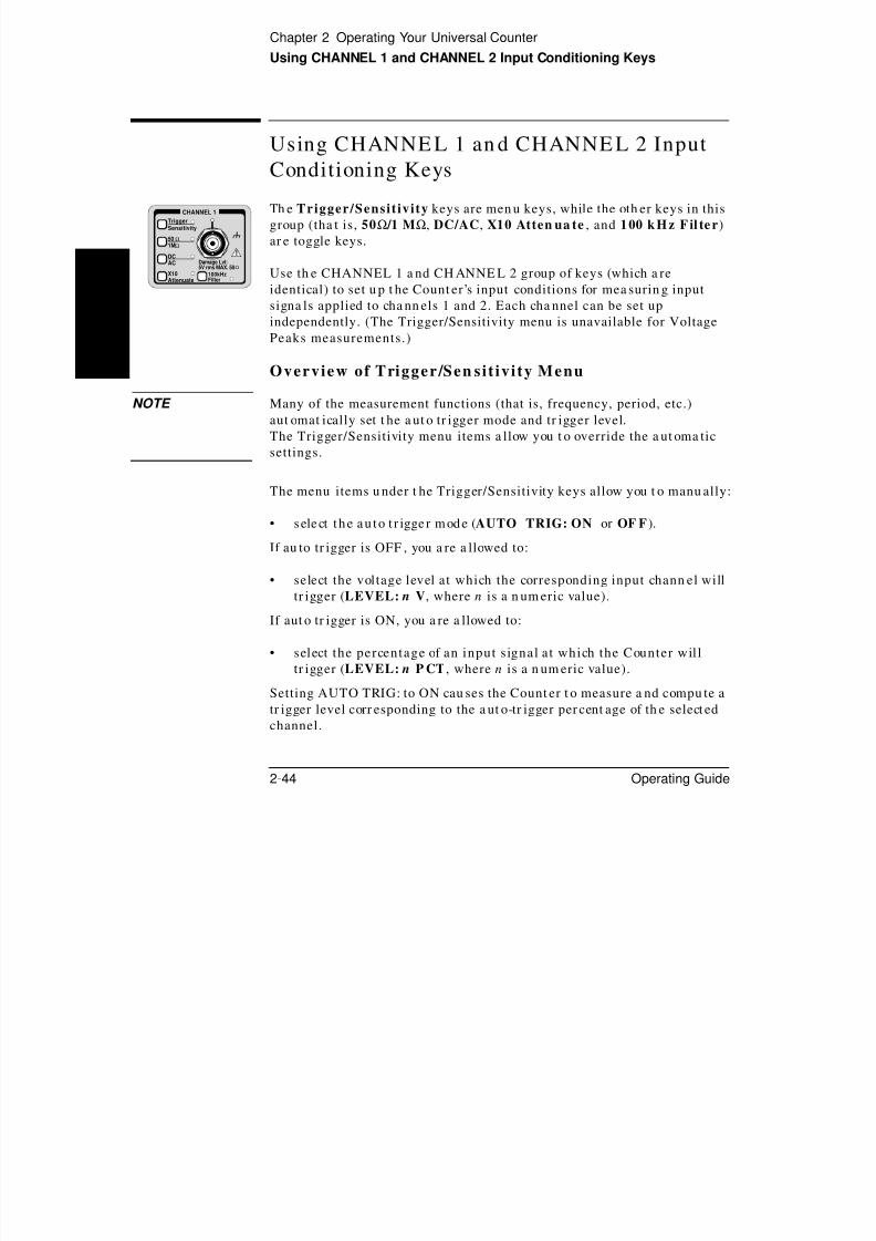
8/4/2019 53131 Operating Guide
http://slidepdf.com/reader/full/53131-operating-guide 120/196
2-44 Operating Guide
2
Use th e CHANNEL 1 a nd CH ANNE L 2 group of keys (which a re
identical) to set u p t he Count er’s input conditions for mea surin g inputsigna ls applied to cha nn els 1 and 2. Each cha nnel can be set up
independently. (The Trigger/Sensitivity menu is unavailable for Voltage
Peaks measurements.)
Overview of Trigger/Sen sit ivity Menu
NOTE Many of the measurement functions (that is, frequency, period, etc.)
aut omat ically set t he a ut o tr igger mode and tr igger level.The Trigger/Sensitivity menu items a llow you t o override the a ut oma tic
settings.
The menu items u nder t he Trigger/Sensitivity keys allow you t o manu ally:
• s elect the au to t r igger mode (AUTO TRIG: ON or OF F ).
If au to tr igger is OFF , you a re a llowed to:
• select the voltage level at which the corresponding input chann el will
tr igger (LEVEL: n V, where n is a n um eric value).
If aut o tr igger is ON, you a re a llowed to:
• select the percentage of an input s ignal at which the Counter will
tr igger (LEVEL: n P CT , where n is a n um eric value).
Setting AUTO TRIG: to ON cau ses the Count er t o measure a nd compu te a
tr igger level corr esponding to the a ut o-tr igger per cent age of th e select ed
channel.
AC
X10Attenuate
100kHzFilter
Damage Lvl:5V rms MAX. 50Ω
Chapter 2 Operating Your Universal CounterUsing CHANNEL 1 and CHANNEL 2 Input Conditioning Keys
While AUTO TRIG: is ON, th e Coun ter will, for ea ch mea su rem ent , check
th at th e measu remen t signal(s) ar e triggering at th e cur rent level(s). If no
tr iggering is foun d, the Counter will measu re a nd compu te n ew trigger
level(s). (While AUTO TRIG: is ON, th e Coun ter also mea su res a nd
compu tes n ew tr igger level(s) whenever m easu ring is invoked with th e
front-panel Stop/ Single and Ru n keys, or whenever t he a ut o-tr igger
percent age is updated.)
The men u item s un der th e Trigger/Sensitivity keys also allow you t o

8/4/2019 53131 Operating Guide
http://slidepdf.com/reader/full/53131-operating-guide 121/196
Operating Guide 2-45
2
manually:
• select what slope or edge (positive or negative) of an input signal will
tr igger th e Count er (SLOPE: POS or NEG).
• select medium, high, or low sensitivity levels (thu s, varying the
hyst eresis window or t rigger ban d) for t he optimu m sen sitivity for
certa in measur ement a pplicat ions (SENSTVTY: MED , HI, or LOW).
Sensitivity is defined in the paragraph titled “Definition of
Sensitivity” starting on page 2-46 .
• select a common input s ignal to make a Time Interval (TI)
measurement (COMMON 1: ON or OF F ). In COMMON 1: ON,
an input signa l applied to CHANNEL 1 is split to allow the Count er to
use it for both CHANNEL 1 a nd CHANNE L 2 input a mplifiers when
th e Count er is operat ing in its Time Int erval (TI 1 TO 2) measu remen t
function. By independent ly adjust ing CHANNEL 1 an d CHANNE L 2
keys, th e Count er perform s a TI measu remen t on a single input signa l
as shown in th e following figur e.
COMMON 1: ON, CHAN 1 SLOPE: POS, CHAN 2 SLOPE: NEG
CHANNEL 1
CHANNEL 2
Chapter 2 Operating Your Universal CounterUsing CHANNEL 1 and CHANNEL 2 Input Conditioning Keys
DEF INITION OF S ENS ITIVITY. Sensitivity is th e lowest a mplitude
signal at a pa rt icular frequency th at t he Count er will coun t. The am plifier
gain an d t he voltage difference between t he inpu t t rigger h ysteresis levels
deter min e th e Coun ter ’s sensit ivity. Sensitivity is specified with th e
tr igger level set at a valu e equal to th e midpoint of th e input signa l.
The input wa veform m ust cross both th e upper an d lower hysteresis levels
to gener at e a coun t a s shown in th e following figure.
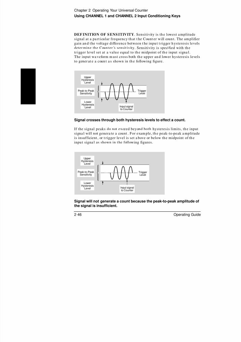
8/4/2019 53131 Operating Guide
http://slidepdf.com/reader/full/53131-operating-guide 122/196
2-46 Operating Guide
2
Signal crosses through both hysteresis levels to effect a count.
If the signal peaks do not exceed beyond both hysteresis limits, th e input
signa l will not genera te a count . For exam ple, th e peak-to-peak a mplitude
is insufficient , or t rigger level is set a bove or below th e midpoint of th e
inpu t signa l as shown in t he following figures.
Signal will not generate a count because the peak-to-peak amplitude ofthe signal is insufficient.
Upper
HysteresisLevel
Peak-to-PeakSensitivity
TriggerLevel
LowerHysteresis
Level Input signalto Counter
TriggerLevel
UpperHysteresis
Level
Peak-to-PeakSensitivity
Lower
HysteresisLevel Input signalto Counter
Chapter 2 Operating Your Universal CounterUsing CHANNEL 1 and CHANNEL 2 Input Conditioning Keys
UpperHysteresis
Level
Peak-to-PeakSensitivity
TriggerLevel
LowerHysteresis
Level Input signalto Counter

8/4/2019 53131 Operating Guide
http://slidepdf.com/reader/full/53131-operating-guide 123/196
Operating Guide 2-47
2 Signal will not generate a count because the trigger level is set belowthe midpoint of the signal, causing the lower hysteresis level to not becrossed.
The sen sitivity specificat ion is given in t erm s of volts r ms for applications
th at involve measu ring a sine wave signal, th ough it sh ould be noted t ha t
a different waveform with t he sa me rm s voltage ma y not t rigger a count .
Since the Count er inpu t does not r espond t o th e rm s value of th e
waveform but only to th e peak -t o-peak valu e, the sen sitivity specificat ion
is also given for volts pea k-to-peak with a minimu m pulse width.
As previously men tioned, the sen sitivity of th e Coun ter can be cha nged by
using th e SENSTVTY: MED , HI, or LOW menu choices in t he
Trigger/Sensit ivity key menu for optimu m sensitivity for cert ain
measu remen t applicat ions. For exam ple, low sensitivity settin g is veryuseful when meas ur ing noisy signals.
to Counter
Chapter 2 Operating Your Universal CounterUsing CHANNEL 1 and CHANNEL 2 Input Conditioning Keys
To Use the Trigge r/Sen sitivity Keys to Adjus t Counte r’s
Triggering Level
Exam ple Procedure for Se t t ing Tr ig ger Vol ta ge an d Sensi t iv i ty Levels
1 Connect a signal to cha nnel 1 inpu t, and set up t he Coun ter t o meas ur e
th e frequ ency of t he signa l. (Refer t o section in t his chapt er t itled
“To Measur e Frequency” if needed.)

8/4/2019 53131 Operating Guide
http://slidepdf.com/reader/full/53131-operating-guide 124/196
2-48 Operating Guide
2
2 Press CHANNEL 1 Trigger/Sensit ivity key.
AUTO TRG: ON is displayed.
3 Pr ess an y one of th e ar row keys to toggle to th e au to tr igger off mode.
AUTO TRG: OFF is displayed.
4 Press Trigger/Sensit ivity key.
LEVEL: 0.000V is displayed. (Actu al valu e ma y be different .)
5 Suppose you wa nt to set t he t rigger level to 1V (actua l value ma y be
differen t). Per form th e following st eps:
a. Press th e appropriate a rrow keys unt il LEVEL: 1.000V is displayed.
b. Press Enter key.
NOTE BE SURE to press the Enter key to complete the nume ric entry .
The t rigger volta ge level for cha nn el 1 is now set t o 1V as s hown in t he
following figur e.
1V
0V
Chapter 2 Operating Your Universal CounterUsing CHANNEL 1 and CHANNEL 2 Input Conditioning Keys
6 Press Trigger/Sensit ivity key.
SLOPE: POS is displayed. The t rigger slope is set a t positive; th us, t he
Count er tr iggers on t he rising edge of th e input signal as sh own in th e
following figure.
1V
0V*
* * *

8/4/2019 53131 Operating Guide
http://slidepdf.com/reader/full/53131-operating-guide 125/196
Operating Guide 2-49
2
If you wan t t o tr igger on t he n egat ive (or falling) edge of th e inpu t s ignal,
then perform the following step.
7 Pr ess an y one of th e ar row keys un til SLOPE: NEG is displayed.
The trigger is set at n egative; th us, th e Count er t riggers on the falling
edge of the in put signa l as s hown in t he following figure.
8 Press Trigger/Sensit ivity key to set th e input cha nnel sensit ivity level.
1V
0V* * * *
Chapter 2 Operating Your Universal CounterUsing CHANNEL 1 and CHANNEL 2 Input Conditioning Keys
9 Pr ess an y one of th e arr ow keys unt il SENSTVTY: HI is displayed.
The Coun ter ’s CHANNEL 1 sensitivity is set high as sh own in t he
following figur e.
1 2 3 4TriggerBand
0V

8/4/2019 53131 Operating Guide
http://slidepdf.com/reader/full/53131-operating-guide 126/196
2-50 Operating Guide
2
The Count er should now be triggering as det ermined by th e sensitivity
level, and displa ying the inpu t signa l’s frequ ency if th e input signal
peak -to-peak volta ge is large enough for t he selected sen sitivity level.
The signal mu st t ra vel completely through t he t rigger ba nd before a validtr igger is recognized.
10 Press a ny one of th e arr ow keys unt il SENSTVTY: LO is displayed.
The Count er’s CHANNEL 1 sensitivity is set low as shown in t he
following figur e.
Band
1 2
TriggerBand0V
Chapter 2 Operating Your Universal CounterUsing CHANNEL 1 and CHANNEL 2 Input Conditioning Keys
Exam ple Pr ocedu re for Us ing Common 1 to Mak e Time
Interva l (TI) Measurements on a Single Sign al
1 Connect a signal to cha nnel 1 of th e Coun ter .
2 Press Time & Period key until TI 1 TO 2 is moment ar ily displayed.
(Note tha t t he Time, Ch1, and Ch2 an nu nciat ors light.)
3 Press Trigger/Sensit ivity key un til COMMON 1: OFF is displayed.
4 Pr ess an y one of th e ar row keys un til COMMON 1: ON is displayed.

8/4/2019 53131 Operating Guide
http://slidepdf.com/reader/full/53131-operating-guide 127/196
Operating Guide 2-51
2 When t he Counter is operat ing in Comm on 1 m ode, the signal a pplied toCHANNEL 1 is u sed for both sta rt an d st op event. The t rigger level, slope,
an d sensitivity for t he st ar t signa l can be modified by using th e
CHANNE L 1 input condit ionin g keys. Wher eas , the t rigger level, slope,
an d sens itivity of th e stop signal can be modified by usin g CHANNEL 2
inpu t condit ioning keys. (See th e figure locat ed at th e end of th e
sub-section of th is section t itled “Overview of Trigger/Sensitivity Men u.”)
Overview o f Inpu t Condit ionin g Toggle Keys
NOTE Identical fun ctions are a vailable on CH ANNE L 1 and CHANNEL 2.
The following text describes only CHANNE L 1 fun ctions (as indicated by
th e “1” in t he display) for simplicity.
The t oggle keys of th e inpu t cha nn els allow you t o:
• select 50Ω input impedance or 1 MΩ input impedan ce for t he inputcha nn el (CH 1: 50 OHM , or 1M OHM ).
• select dc coupling or ac coupling for t he input channel (CH 1: DC ,
or AC ).
• select the at tenuation of s ignals at the input channel. The normal or
“no” at ten ua tion st at e (key indicator OFF) connects t he inpu t signa l
directly to th e input a mplifier. The X10 stat e att enua tes th e input
signa l by a factor of 10.• insert a low pass fi lter into the input channel, which attenuates
frequencies above 100 kH z. When t he 100 kHz filter is en abled, th e
key indicator is ON. When t he filter is disabled (key indicator OF F),
th e Coun ter r esumes norma l operat ion over th e entire bandwidth
(CH 1: LP FILT , or NO FILT ).
Chapter 2 Operating Your Universal CounterUsing the Save and Recall Menus
Using th e Save an d Reca ll Menus
Overview of Save and Recal l Funct ions
The combin ed use of th e Save a nd Recall fun ctions allows you t o save an d
recall the m easurement setups which determ ine how the Count er
measu res, ana lyzes, an d report s an swers. A setup can include the
measu rem ent to be made, th e precision desired, offset a nd scaling factor to
apply, limits t o be met, an d st at istics t o comput e. Setups can also cont rol
Recall Save &
LocalUtility
8/4/2019 53131 Operating Guide
http://slidepdf.com/reader/full/53131-operating-guide 128/196
2-52 Operating Guide
2
apply, limits t o be met, an d st at istics t o comput e. Setups can also cont rol
print ing of hardcopy. Setu ps saved to memory registers a re pr eservedwhen th e Coun ter is powered down or disconn ected from a power sour ce.1
The Sa ve and Recall functions enable faster an d easier operat ion, fewer
operator errors, and minimum tra ining.
Th e Save a nd Recall keys a llow you t o:
• create and save up to 20 d ifferent inst rument measurement se tupsinto inter na l non-volatile m emory (SAVE:).
• recall up to 20 user-selected measurement setups that were previously
saved (RECALL 1, 2, 3, ... 20). With a total of 21 save/recall
registers, th ere a re 20 r egister s a vailable to you for save/recall
opera tions. The Count er a ut oma tically saves the curr ent s etup to
register 0 (RECALL 0) before execut ing a recall function.1
• dele te any of the s aved setups (UNSAVE:).
1 For firmware revisions 3622 and above, RECALL 0 is stored in volatile memory. RECALL 0 is not preservedif you cycle power.
Chapter 2 Operating Your Universal CounterUsing the Save and Recall Menus
To Use the Save Funct ion
The following st ep-by-st ep pr ocedure d escribes how t o SAVE a simp le
measu remen t set up t o quickly get you familiar with th e Save fun ction.
You will SAVE th e following in regist er 1 (SAVE: 1):
• the Per iod measuremen t funct ion ,
• the input cond it ion ing pa ramete rs :
a u to t r igger t o off

8/4/2019 53131 Operating Guide
http://slidepdf.com/reader/full/53131-operating-guide 129/196
Operating Guide 2-53
2
– a u to t r igger t o off
– t r igger leve l to 1 .5V
– in pu t im peda nce to 50Ω
– in pu t cou plin g t o DC
1 Cycle POWER key to preset th e Count er setup.
The Coun ter is now rea dy to mea sur e the frequency of a signa l applied to
CHANNEL 1 input a s indicat ed by th e Freq and Ch 1 annunciators.
2 Press Other Meas key until PERIOD 1 is displayed.
The Coun ter is now ready to measu re th e period of a signa l applied to
CHANNEL 1 input a s indicat ed by th e Period and Ch 1 annunciators.
3 Press Trigger/Sensit ivity key.
AUTO TRG: ON is displayed.
4 Press a ny one of th e ar row keys.
AUTO TRG: OFF is displayed.
5 Press Trigger/Sensit ivity key, or Enter key.
LEVEL: 0.000V is displayed.
6 Using th e appr opriat e ar row keys, set t he t rigger level to 1.5V.

8/4/2019 53131 Operating Guide
http://slidepdf.com/reader/full/53131-operating-guide 130/196
Chapter 2 Operating Your Universal CounterUsing the Save and Recall Menus
To Unsave a Measuremen t Setup
1 To un save th e mea sur ement setup you’ve saved in th e previous pr ocedure,
press Save & Print key until UNSAVE: NO is displayed.
2 Press t he appr opriat e arr ow keys to select UNSAVE: 1, then press Enter
key.
The measurement setup tha t was sa ved in register 1 (RECALL: 1)
is deleted or un saved.
ADDITIONAL INFORMATION ABOUT UNSAVE

8/4/2019 53131 Operating Guide
http://slidepdf.com/reader/full/53131-operating-guide 131/196
Operating Guide 2-55
2
ADDITIONAL INFORMATION ABOUT UNSAVE
If th e UNSAVE: display DOES NOT show up after th e SAVE: display, t hen
no setups ha ve been saved; all registers a re empt y.
If UNSAVE: display is present in th e Save & Print key menu, then a t
least one setup h as been sa ved. (To determ ine how many setu ps ar e saved,
cont inuously press th e key while UNSAVE: n is displayed a nd coun t
th e num ber of registers th at ar e present.) Perform st ep 2, below, to delete
a m easurement setup.
1 Suppose th ere ar e two registers (1 and 2) th at ha ve setu ps saved in th em.
To rem ove th ese set ups, per form th e following:
a. At t he UNSAVE: 1 display, press Enter key.
UNSAVE: 2 is displayed, indicat ing tha t r egister 1 has been cleared.
To check if the clearin g was done, press t he key; th e “1” disp lay
should not exist.
b. At t he UNSAVE: 2 display, press Enter key.
All registers ar e cleared when t he UNSAVE menu item is NOT present
in the Save & Print key menu.
2 Now, sup pose in t he pr evious st ep (2) you wa nt ed to leave register 1 a lone,
but you wa nt to delete register 2. Per form th e following steps:
a. At t he UNSAVE: 1 display, press key.
UNSAVE: 2 is displayed.
b. Press Enter key to delete r egister 2.
Chapter 2 Operating Your Universal CounterUsing the Print Menu
Using the Pr int Menu
Overview of the P rint Menu
The Pr int m enu allows you t o:
• en a ble or d isa ble pr in t in g (PRINT: OFF or ON ).
• get h elp on h ow t o p rin t (PRINT HELP ?).
Save &Print
Local

8/4/2019 53131 Operating Guide
http://slidepdf.com/reader/full/53131-operating-guide 132/196
2-56 Operating Guide
2
To Use the P rint Menu1 Press Save & Print key until PRINT: is displayed.
2 If PRINT: OFF is displayed, press a ny one of the a rr ow keys to toggle th e
next state.
PRINT: ON is displayed.
When PRINT is enabled, th e Coun ter displays and pr ints t he result s foreach mea surem ent . In add ition, if STATS: ON, all sta tistics (th at is,
sta nda rd deviat ion, mean , ma ximu m, and minim um ) will be printed.
NOTE Print ing may slow the upda te ra te of th e Count er becau se the Coun ter
ma y have to wait for th e printer.
3 Press Save & Print key.
PRINT HELP ? is displayed.
4 Press Enter key.
The instr uction “CONFIGURE PORT ON UTILITY MENU; REMEMBER TO
SAVE SETUP FIRST ” is displayed.
5 Save your cur rent setup a s shown in the section t itled “To Use th e Save
Function .”
6 Refer t o the section in th is cha pter titled “To Configure th e RS-232 Seria l
Port for Pr inting” for inform at ion on h ow t o configure a nd conn ect t he
Count er to a print er.
Chapter 2 Operating Your Universal CounterUsing the Utility Menu
Using th e Ut ility Menu
Overview o f the Uti l i ty Men u
The Ut ility men u is a ccessed by holding th e Recal l key a nd cycling
POWER key.
The Ut ility m enu allows you to:
RecallUtility Menu:Hold at power up
Utility
POWER

8/4/2019 53131 Operating Guide
http://slidepdf.com/reader/full/53131-operating-guide 133/196
Operating Guide 2-57
2 • view the firmware revision of your Counter (REV: n ).• select and/or d isplay the cur rent HP-IB address (HP-IB: 1, ... 30, or
TALK).
• choose t imebase sou rce (TIMEBAS: AUTO, IN T, or EXT).
• execute several self tes ts (refer to the paragraph in this section t i t led
“To Run t he Self-Test Routin es” for det a ils).
• configure the following parameters for t he RS-232 port:– set th e pr in t ba ud r at e (BAUD: 9600, 19200, 300, 1200, or 2400).
– set pr int pa rit y (PARITY: OFF , EVEN , or OD D ).
– s et t he soft wa r e p ace (SW PACE: XON or NONE).
– set the hardware pace to send data to a serial pr inter , or to send
th e Limit-detect out put to a comput er or cont roller, via t he
RS-232 port (DTR: HIGH , HW PACE , or LIMIT).
– chan ge the num erical convention of the Count er’s displayed
mea surem ent values. The num eric convention used in the USA
separa tes th e integral an d fra ctiona l port ions of a nu mber with a
period (a decimal point), an d separ at es groups of th ree digits in
th e integer port ion with a comm a. You can r everse th is setting to
conform to th e nu merical convention used in m an y oth er coun tr ies
(SHOW 9 AS: 9.0 or 9,0 ).
Ea rly revisions of the Count er a llowed calibrat ion from t he U tility menu
with CAL: menu item. Calibrat ion a nd t he CAL: menu item n ow reside on
th e Calibra tion menu; the CAL HE LP? menu item resides on th e Utility
menu a s a pointer to the Calibration m enu.
Chapter 2 Operating Your Universal CounterUsing the Utility Menu
To Set the HP -IB Addres s
Ea ch device on t he HP -IB must ha ve a unique addr ess. You can set t he
Count er’s a ddress t o any value between 0 an d 30. The addr ess is set t o “3”when t he Coun ter is shipped from th e factory.
Select ing Opera t ing Mode (Ta lk/Lis ten, Ta lk-Only)
The Coun ter h as t wo HP -IB operat ing modes:
• Addressed (talk/listen)—This mode is for bi-directionalcomm unication. The Coun ter can receive comm an ds an d setu ps from
8/4/2019 53131 Operating Guide
http://slidepdf.com/reader/full/53131-operating-guide 134/196
2-58 Operating Guide
2
the computer, an d can send dat a an d measurement results.To select the talk/l isten operatin g mod e, set the Counte r’sHP-IB ad dress from 0 to 30. Refer to t he following su b-section tit led“Sett ing the H P-IB Address” for in str uctions on h ow t o select a nHP -IB addr ess from th e front pa nel.
• Talk-only—In this mode, the Counter can send data to a printer .It can not receive comm an ds or setu ps from the compu ter .
To select the ta lk-only ope rating mo de, set the Coun ter’sHP -IB m ode to “TALK”. Refer t o th e section t itled “To Select t heHP -IB Talk-Only Mode for Prin tin g” for inst ru ctions on how t o selecttalk-only operating mode.
Set t in g the HP-IB Add ress
1 Press an d hold Recall (Util ity) key, th en cycle POWER key.
REV: n is displayed; where “n” represents the numeric firmware revisioncode.
2 Press Recall (Utility) key unt il HP-IB: is displayed.
HP-IB: 3 is displayed, for exam ple.
3 To set t he a ddress t o 15 (for exam ple), use th e appr opriat e ar row keys toenter t he value 15, then press Enter key.
NOTE BE SURE to press the Enter key to complete the nume ric entry .
The addr ess is now stored in non-volatile memory, an d does not changewhen power ha s been off or a fter a r emote interface reset.
Chapter 2 Operating Your Universal CounterUsing the Utility Menu
To Choo se the Timebase So urce
1 Press a nd hold Recall (Utility) key, th en cycle POWER key.
2 Press Recall (Utility) key un til TIMEBAS: is displayed.
3 Pr ess an y one of th e ar row keys u nt il desired choice (th at is, AUTO , INT , or
EXT ) is displa yed.
To Run th e S elf-Test Routine s

8/4/2019 53131 Operating Guide
http://slidepdf.com/reader/full/53131-operating-guide 135/196
Operating Guide 2-59
2 Overview of the S elf-Test Rout inesThe Ut ility men u in cludes t he following thr ee self-test menu items:
• TEST LOOP:
• TST PRINT:
• TEST:
The Count er includes several self-tests. Some self test s ar e perform ed atth e poweru p of th e Coun ter . Some of th ese self test s can a lso be invoked
from th e Ut ility menu. Oth er t ests can a lso be invoked from t he Ut ility
menu , but a slightly different test is perform ed. For example, a powerup
self test might work r egardless of connections t o th e input s while a Ut ility
men u self test m ay r equire a specific signal t o be conn ected. Some self test s
can only be invoked from th e Ut ility men u, for exam ple, th e keypad t est.
You can specify th at t he t ests should loop forever (TEST LOOP: ON orOFF ) or u nt il any key is pressed.
You can also specify tha t failure m essages be sent t o a print er, th e RS-232,
an d th e HP -IB—if in t alk-only (TST PRINT: ON or OFF ).
Chapter 2 Operating Your Universal CounterUsing the Utility Menu
There a re 13 choices for t he TEST: menu item. They are listed a nd
described in t he following t ext.
TEST: ALL? — run all tests, except display, keypad an d printer tests.
DISP? — illumin at e th e indicat ors and vacuum -fluorescent
display (VFD) segment s. Note, this t est is not available
if TEST LOOP: is ON . TEST LOOP: m ust be OFF.
CPU? — test processor(s).
ROM? — checksum the ROM.

8/4/2019 53131 Operating Guide
http://slidepdf.com/reader/full/53131-operating-guide 136/196
2-60 Operating Guide
2 RAM? — test RAM.
EEPROM? — checksum t he E EP ROM, which is used for n on-volatile
memory.
HP-IB? — test HP-IB chip.
QSPI? — test serial har dware contr ol loops.
FPGA? — internally measure th e timebase to test count
circuitry.
FR END? — check front end circuits, eith er by swinging tr igger
levels (dur ing power on test an d ALL test ) or a sking
you t o connect the t imebase output to chan nels 1 and 2
using a BNC-T conn ector t o split th e signal.
MEAS? — mak e a measurement , either by swinging trigger
levels (dur ing power on test an d ALL test ) or a sking
you t o conn ect t he t imebase out put to cha nn el 1.
INTERP? — test interpolators .
KEYPAD? — request user to press all keys. Note, this test is n ot
available if TEST LOOP: is ON . TEST LOOP: m ust beOFF.
PRINT? — send three test lines to a printer via the RS-232. If in
ta lk-only, also send t hr ee test lines to a print er via th e
HP-IB.
Chapter 2 Operating Your Universal CounterUsing the Utility Menu
Exam ple Pr ocedu re for R unnin g t he Se l f Tes t
1 Press a nd hold Recall (Utility) key, th en cycle POWER key.
2 Press Recall (Utility) key un til TEST: is displayed.
3 Pr ess an y one of th e ar row keys to select t he desired men u choice in t he
menu item (for exam ple, th e ALL? menu choice).
4 Press Enter key to start t he test.

8/4/2019 53131 Operating Guide
http://slidepdf.com/reader/full/53131-operating-guide 137/196
Operating Guide 2-61
2 5 If you a re a sked t o do something, press Enter key when you h avecompleted th e requested ta sk.
A pass or fail mess age will be displayed.
To Con figure the RS-232 Se rial Port for Printin g
Softwar e pacing, bau d ra te, par ity, dat a bits, an d stop bits pa ra met ers for
each port ar e u ser-selecta ble and independent of configura tion of theother.
The ta ble below lists t he configur at ion factory-default va lues for t he
RS-232 port .
1 When parity is EVEN or ODD, data bits are fixed at 7. When parity is NONE, data bits are fixed at 8.
Parameter Default Possible Choices
Software Pacing XON XON or NONE
Baud Rate 9600 300, 1200, 2400, 9600, or 19200
Parity NONE EVEN or ODD1 NONE
Data Bits 8 FIXED at 7 FIXED at 8
Stop Bits 1 FIXED
Full Duplex ON ON or OFF
DTR HIGH PACE, HIGH, LIMIT
Chapter 2 Operating Your Universal CounterUsing the Utility Menu
Configuring th e RS-232 serial port for pr inting r equires th at you:
• set the hardware pacing in the DTR (Data Terminal Ready) menu item,
• turn PRINT:ON in th e SAVE&PRINT men u,
• set t h e ba u d r a t e in t h e BAU D m en u it em ,
• set the par i ty type in the PARITY menu item, and
• set the software pacing in the SW PACE menu item.
Se t t ing the Hard wa re Pac ing
1 P d h ld R ll (Util it ) k h l POWER k

8/4/2019 53131 Operating Guide
http://slidepdf.com/reader/full/53131-operating-guide 138/196
2-62 Operating Guide
21 Press an d hold Recall (Util ity) key, th en cycle POWER key.
2 Press Recall (Utility) key unt il DTR: is displayed.
3 Press a ny one of th e arr ow keys until th e desired ha rdwar e pacing is
displayed.
NOTE • Choose HW PACE to use t he DTR line for pa cing.(CAUTION: You
should only choose th is opt ion i f your printer and cable
support DTR handshaking.)
• Choose HIGH to disable ha rdwar e pacing.
The Count er’s ta lk-only RS-232 port is n ow set to be th e driver for a
RS-232 serial prin ter . The har dwar e pacing choice is stored in non-volatile
memory, an d does not cha nge when power ha s been off or after a remoteinterface reset.
Se t t ing the Baud Ra t e
You can select one of five baud ra tes for RS-232 opera tion. The r at e is set
to 9600 baud wh en t he Coun ter is shipped from th e factory.
1 Press Recall (Utility) key unt il BAUD: is displayed.
2 Press a ny one of th e arr ow keys unt il th e desired baud ra te is displayed.
The baud ra te is stored in non-volatile memory, an d does not cha nge when
power h as been off or a fter a remote int erface reset.
Chapter 2 Operating Your Universal CounterUsing the Utility Menu
Se t t ing the Par i t y
You can select th e par ity for RS-232 oper at ion. The Coun t er is configur ed
for pa rit y off when sh ipped from th e factory.
1 Press Recall (Utility) key un til PARITY: is displayed.
2 Pr ess an y one of th e ar row keys un til the desired pa rity is displayed.
The pa rit y choice is st ored in non-volatile memory, an d does not change
when power ha s been off or a fter a remote int erface reset.

8/4/2019 53131 Operating Guide
http://slidepdf.com/reader/full/53131-operating-guide 139/196
Operating Guide 2-63
2 Se t t ing the Softwa re Pa ce
You can select t he s oftwar e pace for RS-232 opera tion.
1 Press Recall (Utility) key un til SW PACE: is displayed.
2 Pr ess an y one of th e ar row keys un til th e desired softwa re pa cing is
displayed.
The s oftwa re pa cing choice is st ored in non-volatile memory, an d does not
cha nge when power has been off or a fter a r emote inter face reset.
Chapter 2 Operating Your Universal CounterUsing the Utility Menu
To Configure the RS-232 Serial Port for Sendin g
Limit-Dete ct Outpu t
NOTE If you cycle power, you will lose everyt hin g except sa ved mea sur emen t
setups an d special par am eters stored in non-volatile memory; th erefore,
ma ke sur e you use t he Save fun ction of th e Coun ter t o reta in th e
measu remen t set up pr ior t o powering down to set up t he Limit-Detect
Out put line (pin 4) of RS-232 seria l connector. Refer t o th e appr opriat e
section in th is cha pter for details on how to use Sa ve and Recall.
1 To use the Limit detect output from the serial port perform the following
8/4/2019 53131 Operating Guide
http://slidepdf.com/reader/full/53131-operating-guide 140/196
2-64 Operating Guide
21 To use the Limit-detect output from the serial port, perform the following
steps:
a. Save your measurement setup t hat includes your Limit Testing
choices, by simply pressin g th e Save & Print key until
SAVE: 1 is displayed, then Enter key to save to register 1.
b. Turn off the Coun ter .
c. Press a nd hold Recall (Utility) key, th en press POWER key.
d. Press Recall (Util ity) key un til DTR: is displayed.
e . Pr ess an y one of th e ar row keys un til DTR: LIMIT is displayed.
2 Press Run key.
3 Press Recall (Utility) key un til RECALL 1 is displayed, then wait a few
seconds to recall the mea sur ement setu p saved in register 1.
Since your mea sur ement setu p included your sett ings for u pper a nd lower
limits, an d LIM TEST: was set to ON , the Count er is n ow set for limit
test ing with th e Limit-detect output .
If a mea sur ement drifts out of th e user-entered limits, the Limit
an nu nciat or in th e display will light . Also, pin 4 on th e RS-232 conn ector
will cha nge s ta te (to a low-volta ge RS-232 level) to flag ea ch tim e amea sur emen t dr ifts out of th e limit s. (RS-232 volta ge levels swing
from ±12V.)
Chapter 2 Operating Your Universal CounterUsing the Utility Menu
To Select the Nume rical Convention for the Display
1 Press a nd hold Recall (Utility) key, th en cycle POWER key.
2 Press Recall (Utility) key un til SHOW 9 AS: is displayed.
3 Pr ess a ny one of the a rr ow keys un til your menu choice is displayed.
If you choose SHOW 9 AS: 9.0 , th e Coun ter will display a frequency
measurement similar to 12.0000000001 MHz , for exam ple. Note tha t t he
integral portion (12) is separated from the fractional portion of the
num ber by a period (or decima l point ) This n um erical convent ion is u sed

8/4/2019 53131 Operating Guide
http://slidepdf.com/reader/full/53131-operating-guide 141/196
Operating Guide 2-65
2 num ber by a period (or decima l point ). This n um erical convent ion is u sedin the US A.
If you choose SHOW 9 AS: 9,0 , th e Coun ter will display a frequency
measurement similar to 12,0000000001 MHz , for exam ple. Note tha t t he
integral portion (12) is separated from the fractional portion of the
num ber by a comma. This num erical convention is used in m an y oth er
countries.
Your n um erical convent ion choice for t he disp lay is st ored in non-volatile
memory, an d does not cha nge when power ha s been off or a fter a r emote
interface reset.
To Conn ect the Counter to a Serial Printer via the
RS-232 Po rt
The RS-232 port on th e Coun ter ’s r ear pan el is a 9-pin conn ector (DB-9,ma le conn ector). You can connect t he Count er t o any print er with a
properly configured DTE conn ector (DB-25). You can u se a st an dar d
HP 24542G or 24542H interface cable.
Connect t he Count er t o a t ermina l or pr inter by simply insta lling an
RS-232 cable (such as a n AT Prin ter Cable—HP P /N 24542H cable)
between th e units.
Chapter 2 Operating Your Universal Counter
Using the Utility Menu
To Conn ect the Counter to a P rinter via HP-IB
You can conn ect t he Counter to a pr inter via H P-IB eith er with or with out
a compu ter. If you conn ect a compu ter, you can opera te t he prin ter un derprogra m cont rol. In the a bsence of a comput er, the Count er, when in ta lk-
only, becomes th e cont roller for th e prin ter .
To Sele ct the HP -IB Talk-Only Mode for Printin g
1 Press a nd hold Recall (Util ity) key, th en cycle POWER key.
2 Press Recall (Utility) key unt il HP-IB: is displayed.

8/4/2019 53131 Operating Guide
http://slidepdf.com/reader/full/53131-operating-guide 142/196
2-66 Operating Guide
23 To set t he HP -IB to talk-only, press t he a ppropriate a rrow keys unt il
HP-IB: TALK is displayed.
The TALK choice follows 30 a nd precedes 0 in th e set of choices for th e
HP-IB menu item.
NOTE BE SURE to press the Enter key to complete the nume ric entry .
The ta lk-only opera tin g mode is now st ored in non-volatile memory, an d
does not change when power ha s been off or a fter a r emote interface reset.

8/4/2019 53131 Operating Guide
http://slidepdf.com/reader/full/53131-operating-guide 143/196
Chapter 2 Operating Your Universal Counter
Using the Calibration Menu
2
• view the calibration count, which indicates the number of t imes that
th e Count er ha s been calibra ted (CAL COUN T?). The calibra tion
coun t in cremen ts u p to a m aximum of 32,767 after which it wra ps
ar oun d to 1. A calibrat ion coun t of 0 indicat es th at th e Coun ter iscomplet ely uncalibra ted. (The calibra tion coun t is un affected by
interpolator calibrat ion.)
• get Help (HELP:) with a ny of the following:
– h ow t o ca libr at e (CAL?),
– h ow t o secu re (SECURE?), an d
– how to change the code (CODE?)

8/4/2019 53131 Operating Guide
http://slidepdf.com/reader/full/53131-operating-guide 144/196
2-68 Operating Guide
2
NOTE A good pr ecau tion is to use an HP -IB program (see the progra mm ing
example titled “To Read a nd St ore Calibrat ion Da ta ” in Cha pter 3 of the
Programm ing Guide) to read a nd st ore t he calibration factors prior t o
initiating a ny calibrat ion.
To View the Calibrat ion Menu an d Secu rity StatusThe Calibra tion men u is a ccessed by holding th e Sca le & Offset key an d
cycling the POWER key. The first it em in t he Calibrat ion m enu is a
message indicat ing the calibra tion secur ity stat us: CAL SECURE or
CAL UNSECURE .
To Unse cure for Calibration
1 Press an d hold Sca le & Offset key, th en cycle POWER key.
CAL SECURE is displayed.
If CAL UNSECURE is displayed, th en th e Count er is already un secur ed
for calibra tion, an d th e rema ining steps a re n ot a pplicable.
2 Press Sca le & Offset key until CODE: is displayed.
3 Press t he appr opriat e arr ow keys to enter t he secur ity code, then press
Enter key.
CAL UNSECURE is displayed.
Chapter 2 Operating Your Universal Counter
Using the Calibration Menu
2
To Init iate the Calibration Rou tines
1 Press a nd hold Sca le & Offset key, th en cycle POWER key.
2 Unsecure for calibration by performing the preceding procedure.
3 Press Sca le & Offset key until CAL: OFFS1? is displayed.
4 Pr ess a ny one of the a rrow keys unt il your calibrat ion choice (that is,CAL: OFFS2? , CAL: GAIN 1? , CAL: GAIN 2? , CAL: TI QUIK? ,CAL: TI FINE? , or CAL: TIMEBAS? ) is displa yed.
Note tha t t he tim ebase choice (CAL: TIMEBAS?) only appear s when aTi b O i i i ll d

8/4/2019 53131 Operating Guide
http://slidepdf.com/reader/full/53131-operating-guide 145/196
Operating Guide 2-69
2
Timebase Option is insta lled.
CAL:TI QUIK? and CAL:TI FINE? ar e two different ways t o calibrat eout th e differences in electr ical pat h length between Chan nel 1 an dChan nel 2. When you pr ovide th e calibrat ion signal, the inst rum entmeasu res how th e difference in pat h length tr an slates to an avera ge delaybetween th e two chann els.
The Quick Time Int erval Calibration requires a s imple inpu t signal.You provide on Cha nn el 1 a clean squa re wave with a r apid rise time andan a pproximat e frequency of 10 MHz. The inst ru men t routes t hecalibrat ion signal in COMMON to both cha nnels 1 an d 2, an d mea suresth e avera ge delay between th e two cha nn els so configur ed. The advant ageof the Qu ick Ca librat ion is t ha t it is eas y, quick, an d requires litt le specialequipment . The disadvant age is tha t t he calibrat ion ter m is best fit for
TI measur ements configured COMMON an d measu red from rising torising edge; it leaves u ncorr ected a sma ll systemat ic err or for all otherconfigura tions. The F ine Time Inter val Calibrat ion m inimizes systema ticerror by calibrat ing the inst ru ment in each configura tion.
The Fine Time Int erval Calibration requires a s pecial calibrat or signalsource to pr ovide inpu t—becau se it produces eight calibra tion ter ms, each
tailored to a different combination of input conditions. It requires the
synthesizer driving th e calibrat or t o produce a very accur at e 10 MHz
waveform —becaus e it calibra tes t he pu lse width configurat ion a gainst th e
50-nanosecond pulse width so provided. It minimizes systematic error by
calibrat ing th e instr um ent in each of th e eight configura tions: falling to
falling edges, falling to rising edges, etc., an d both SE PARATE a nd
COMMON routing.
Chapter 2 Operating Your Universal Counter
Using the Calibration Menu
2
5 Press Enter key to display the setu p instr uctions.
Notes Per ta ini ng t o the CAL: TI QUIK?
Advantage: Calibra tion signal is simple.
Disadvantage: One corr ection ter m for all slope an d rout ingconfigurations.
Input signal: clean squa re wave, fast r ise time, appr oxima tely 10 MHz,1 volt peak-to-peak , no dc offset (oscillat ing about 0.0 volts), driving 50Ω.
Timebase: Any exter na l timebase you pr ovide is ignored du ringcalibration.

8/4/2019 53131 Operating Guide
http://slidepdf.com/reader/full/53131-operating-guide 146/196
2-70 Operating Guide
2
Procedure: Fr om t he front -pan el calibrat ion m enu, one keypressinvokes t he calibrat ion.
Notes Per ta ini ng to th e CAL: TI FINE?
Advantage: Calibration minimizes systema tic error for a ny
supported combinat ion of inpu t slope an d r out ing.
Disadvantage: Calibra tion signa l is more complex. If you perform acalibration th at you feel is erroneous a nd do not feel you can performth e fine calibration, perform the CAL: TI Q UIK? calibration in stead,or restore the calibration factors that you saved prior to starting.
Equipment: HP 8130A Pu lse Generat or or equivalent.HP 59992A J 06 Time Int erval Calibra tor or equivalent .
Equipment and Counter Setup: See Figure 2-4.
Figure 2-4. Calibration Setup for CAL: TI FINE?
HP 53131A/132ACounter
1 2 3 4
In A B
HP 59992A J06Time Interval Calibrator
Start Stop
HP 8130APulse Generator
Output
Chapter 2 Operating Your Universal Counter
Using the Calibration Menu
2
Out of HP 8130A, into HP 59992A J06 Calibrator Sig na l:
PERIOD: 100 ns
WIDTH: 50 nsHigh: 0.50 V Low: −0.50 V
Input Mode: Norma l
Timebase: Any extern al t imebase you provide is ignored du ring
calibration.
Procedure: Fr om t he front -pan el calibrat ion m enu, one keypress
invokes th e calibrat ion. You a re pr ompt ed to press but tons on th eHP 59992A J 06 Calibrat or for each par t of a four-par t calibra tion
8/4/2019 53131 Operating Guide
http://slidepdf.com/reader/full/53131-operating-guide 147/196
Operating Guide 2-71
HP 59992A J 06 Calibrat or for each par t of a four-par t calibra tion.
Note tha t CAL: TI FINE? requ ires t he complet ion of four st eps in
order.
To Secu re Against Calibrat ion
1 Press a nd hold Sca le & Offset key, th en cycle POWER key.
CAL UNSECURE is displayed. If CAL SECURE is displayed, th en th e
Count er is already secur ed against calibra tion and th e rema ining steps
ar e not a pplicable.
2 Press Sca le & Offset key until CODE: is displayed.
3 Pr ess th e appropriate a rr ow keys to ent er th e secur ity code, th en pressEnter key.
CAL SECURE is displayed.
Chapter 2 Operating Your Universal Counter
Using the Calibration Menu
2
To Chan ge to a New Secu rity Code
1 Press a nd hold Sca le & Offset key, th en cycle POWER key.
2 Unsecure for calibrat ion by t he u sing th e procedure described in t he
section t itled “To Un secure for Ca librat ion .”
3 Press Sca le & Offset key until CODE: is displayed.
4 Press t he appr opriat e arr ow keys to enter t he new or cust omized secur ity
code, then pr ess Enter key.
A scrolling message will app ear , indicat ing wha t t he n ew code is.

8/4/2019 53131 Operating Guide
http://slidepdf.com/reader/full/53131-operating-guide 148/196
2-72 Operating Guide
For example, the Count er displays the NEW CODE IS 5 if you entered “5”
as t he n ew code.
To View the Calibrat ion Coun t
1 Press an d hold Sca le & Offset key, th en cycle POWER key.
2 Press Sca le & Offset key until CAL COUNT? is displayed.
3 Press a ny one of the en tr y keys (ar row, +/ −, Enter) to have a scrolling
message appear , indicat ing what th e calibrat ion coun t is.
Your Count er wa s calibrat ed before it left t he factory. When you receive
your Coun ter, rea d th e calibrat ion count to determin e its initial value.
To Get He lp With the Calibration Men u
1 Press an d hold Sca le & Offset key, th en cycle POWER key.
2 Press Sca le & Offset key until HELP: CAL? is displayed.
3 Press a ny one of the a rr ow keys unt il your help choice (that is,
HELP: CAL? , HELP: SECURE? , HELP: CODE? ) is displayed.
4 Press Enter key to display the help inform at ion.
Chapter 2 Operating Your Universal Counter
Front Panel Display Messages
2
Fr ont Pa nel Display Messages
Ther e ar e four types of displays:
• Me as ur em en t Res ult Disp la ys
• Power -Up/Self Tes t M essages
• Men u Messa ges
• H P-IB Messa ges
Measu remen t Result Displays

8/4/2019 53131 Operating Guide
http://slidepdf.com/reader/full/53131-operating-guide 149/196
Operating Guide 2-73
Measu remen t Result Displays
1 If this condition recurs, your Counter may need servicing.
Table 2-4. Measurement Result Displays
Display Me ssage P robable Cause
NEW TIMEBASE You have selected the auto reference mode (TIMEBAS: AUTO ) and the Counter
detected that the external reference became invalid during the measurement.
Therefore, the current result is not valid, and the Counter switches to using theinternal reference.
NO TIMEBASE You have selected external reference (TIMEBAS: EXT ) and there is no externalreference applied to the rear-panel Ref In connector, or the external signal is not
an allowed frequency.
1INTERP FAIL Interpolator calibration failed on the last measurement; therefore, no valid
measurement was taken.
1MEAS FAIL A measurement calibration failed on the last measurement.
DOING STATS You have chosen to see a statistics result and the Counter is calculating
statistics, but does not have valid statistics results yet.
_ _ _ _ _ _ _ _ _ _ _ _ There is no valid measurement available to display. The Counter may be stopped
between measurements while in Single mode, and you need to press theStop/Single key; or trigger level or input conditioning may need adjustment.
Chapter 2 Operating Your Universal Counter
Front Panel Display Messages
2
Po w er-Up/Self Test Messa ges
The following sequence occur s when you tu rn on the Coun ter :
1. All of the vacuum-fluorescent display segments and t he indicators
(or LEDs) ar e illum inat ed for th e power-up test.
2. I f a ll t es t s p as s: SELFTST: PASS will be displayed (See N OTE below).
3. HP-IB AT X will be momenta rily displayed (where X represen ts th e
HP-IB address number), then th e Count er will star t t aking
measur ements. (Note: Ea rlier versions of the Counter do not display
the HP-IB address.)
NOTE If th ere is a failure each t est t hat fails will display a failure m essage and

8/4/2019 53131 Operating Guide
http://slidepdf.com/reader/full/53131-operating-guide 150/196
2-74 Operating Guide
NOTE If th ere is a failure, each t est t hat fails will display a failure m essage, and
SELFTST: FAIL will be displayed. You m ust pres s an y key in order for t he
Coun ter to go on.
Possible individual failure m essages a re:
FAIL: DISP display t estFAIL:CPU processor tes t
FAIL: ROM ROM test
FAIL:RAM RAM t est
FAIL: EEPROM EEP ROM test
FAIL: HP-IB HP-IB hardware test
FAIL: QSPI serial ha rdwa re loops test
FAIL: FPGA count circuit test
FAIL: FR END front end t estFAIL: MEAS measurement test
FAIL: INTERP interpolator test
In a ddition, th e following power-up m essa ge ma y be displayed:
UNCALIBRATED
This mean s th at at least one type of calibrat ion ha s NOT been perform ed.
Chapter 2 Operating Your Universal Counter
Front Panel Display Messages
2
Men u Messa ges
Table 2-5. Menu Messages
Display Me ss age De scription
(AC COUPLED) You have selected the VOLT PEAKS function to be measured on a channel whichis ac coupled.
BAD CODE The Counter’s calibration is secured and you have entered an incorrect code.
CAL ABORTED Calibration was aborted because of HP-IB or the user pressing a key besides theEnter key.
CAL SECURE You are in the Calibration menu, and the first menu item indicates that theCounter is secure against calibration.
8/4/2019 53131 Operating Guide
http://slidepdf.com/reader/full/53131-operating-guide 151/196
Operating Guide 2-75
CAL UNSECURE You are in the Calibration menu, and the first menu item indicates that the
Counter is unsecure for calibration.
CALIBRATING You have invoked calibration from the Calibration menu item CAL: , and theCounter is currently performing the calibration.
1EEPROM FAIL You have requested that a Counter setting which is stored in the EEPROM
(HP-IB: , BAUD: , PARITY: , SW PACE: , DTR: , SHOW 9 AS: , or CAL: ) beupdated, and a hardware failure has resulted.
GAIN 1 FAIL You have invoked the GAIN 1 ? choice from the Calibration menu item CAL: , and
the calibration failed.
GAIN 1 PASS You have invoked the GAIN 1 ? choice from the Calibration menu item CAL: , and
the calibration passed.
GAIN 2 FAIL You have invoked the GAIN 2 ? choice from the Calibration menu item CAL: , and
the calibration failed.
GAIN 2 PASS You have invoked the GAIN 2 ? choice from the Calibration menu item CAL: , and
the calibration passed.
IN REMOTE You have pressed a key (other than Local) while in remote.
LOCAL LCKOUT You have pressed the Local (Save & Print) key while in remote with local lockout.
OFFS 1 FAIL You have invoked the OFFS 1 ? choice from the Calibration menu item CAL: ,
and the calibration failed.
OFFS 1 PASS You have invoked the OFFS 1 ? choice from the Calibration menu item CAL: ,
and the calibration passed.
Chapter 2 Operating Your Universal Counter
Front Panel Display Messages
2
OFFS 2 FAIL You have invoked the OFFS 2 ? choice from the Calibration menu item CAL: ,and the calibration failed.
OFFS 2 PASS You have invoked the OFFS 2 ? choice from the Calibration menu item CAL: ,
and the calibration passed.
NO GATE MENU You currently have the VOLT PEAKS function selected and requested the Gate &
Ext Arm menu.
NO LIM MENU You currently have the VOLT PEAKS or TOTALIZE function selected and
requested the Upper & Lower or Limit Modes menu.
NO MATH MENU You currently have the VOLT PEAKS or TOTALIZE function selected and
Table 2-5. Menu Messages (continued)
Display Me ssag e De scription

8/4/2019 53131 Operating Guide
http://slidepdf.com/reader/full/53131-operating-guide 152/196
2-76 Operating Guide
1 If this condition recurs, your Counter may need servicing.
y
requested the Scale & Offset menu.
NO REGISTERS There are no registers which can be recalled and you selected the Recall menu.
NO STAT MENU You currently have the VOLT PEAKS or TOTALIZE function selected and
requested the Stats menu.
NO TRIG MENU You currently have the VOLT PEAKS function selected and requested theTrigger/Sensitivity menu.
1RECALL FAIL You have requested the Counter to perform a recall (from the Recall menu) and ahardware failure has resulted.
1SAVE FAIL You have requested the Counter to perform a save (from the Save & Print menu)
and a hardware failure has resulted.
TB CAL FAIL You have invoked the TIMEBAS? choice from the Calibration menu item CAL: ,
and the calibration failed.TB CAL PASS You have invoked the TIMEBAS? choice from the Calibration menu item CAL: ,
and the calibration passed.
TI CAL FAIL You have invoked the TI QUIK? or TI FINE? choice from the Calibration menu
item CAL: , and the calibration failed.
TI CAL PASS You have invoked the TI QUIK? or TI FINE? choice from the Calibration menu
item CAL: , and the calibration passed.
Chapter 2 Operating Your Universal Counter
Front Panel Display Messages
2
HP-IB Messages
1 +nnnn and −nnn represent HP-IB error code numbers that would actually be displayed.
Table 2-6. HP-IB Messages
Display Me ss age De scription
1HP-IB +nnnn You have generated the HP-IB error corresponding to the indicated error number.Refer to Chapter 5, “Errors,” in the Programming Guide for a list of the error
descriptions.
1HP-IB −nnn You have generated the HP-IB error corresponding to the indicated error number.Refer to Chapter 5, “Errors,” in the Programming Guide for a list of the error
descriptions.

8/4/2019 53131 Operating Guide
http://slidepdf.com/reader/full/53131-operating-guide 153/196
Operating Guide 2-77
Chapter 2 Operating Your Universal Counter
Preset Values After Power-Up and *RST
2
Preset Values After P ower-Up an d *RST
This section provides separa te preset value lists for t he HP 53131A an d
th e HP 53132A with a serial nu mber pr efix below 3646 (Table 2-7A) an d
HP 53132A with a serial nu mber pr efix of 3646 an d above (Table 2-7B) t o
ma ke it easy for you to different iate from t he coun ters, wh ich ha ve
different ar ming capa bilities for t he Time Inter val measu remen ts.
This section cont ains th e following preset valu e sections or t ables:
• HP 53131A (and HP 53132As with serial num ber prefixes below 3646 )
Pr eset Values for F un ctions Accessible Via Fr ont Pa nel or HP -IB,
starts on page 2-79.

8/4/2019 53131 Operating Guide
http://slidepdf.com/reader/full/53131-operating-guide 154/196
2-78 Operating Guide
p g
• HP 53132A (with serial nu m ber prefixes 3646 and above) Pr eset
Values for F un ctions Accessible Via Fr ont P an el or H P-IB, starts on
page 2-85.
• H P 53131A/132A (all HP 53131As and HP 53132As) Preset Values for
Fu nctions Accessible Via H P-IB Only, starts on page 2-91.
Chapter 2 Operating Your Universal Counter
Preset Values After Power-Up and *RST
2
HP 53131A (and HP 53132A With S/N Pref ix Below
3646) Preset Values for Func t ions Accessible Via Front
Pa ne l or HP-IB
Table 2-7A lists preset values for th e HP 53131A (and th e HP 53132A
with s eria l num ber pr efix below 3646).
Table 2-7A. HP 53131A (and HP 53132A With S/N Prefix Below 3646) Preset Values
Descript ion
In
Save/Recall
Value at *RST
(HP-IB Reset)
Value at
Power-Up
In
Non-Volatile
Memory
Function-Select Parameters
M f i FREQ1 FREQ1

8/4/2019 53131 Operating Guide
http://slidepdf.com/reader/full/53131-operating-guide 155/196
Operating Guide 2-79
Measurement funct ion yes FREQ1 FREQ1 no
Frequency, Period, and Ratio
Arming Parameters
Frequency arm yes ________ TIME no
Frequency star t arm yes IMMedia te ________ no
Frequency stop arm yes TIMer ________ no
Frequency stop a rm digits yes 4 4 no
Frequency gate t ime yes 100.E-3s 100.E-3s no
Frequency ext sta r t a rm slope yes POS POS no
Frequency ext stop arm yes ________ AUTO no
Totalize Arming Parameters
Tota lize arm yes ________ TIME no
Tota lize sta r t arm yes IMMedia te ________ no
Tota lize stop arm yes TIMer ________ no
Tota lize ga te t ime yes 100.E-3s 100.E-3s no
Tota lize ext st ar t a rm slope yes POS POS no
Tota lize ext stop arm yes ________ EDGE no
Chapter 2 Operating Your Universal Counter
Preset Values After Power-Up and *RST
2
Phase Arming Parameters
Phase arm yes IMMedia te AUTO no
Phase ext sta r t a rm slope yes POS POS no
Time Interval, Rise, Fall, Pulse,
Dutycycle Arming Parameters
Time Interval a rm yes ________ AUTO no
Time In terval sta r t a rm yes IMMedia te ________ no
Table 2-7A. HP 53131A (and HP 53132A With S/N Prefix Below 3646) Preset Values (continued)
Descript ion
In
Save/Recall
Value at *RST
(HP-IB Reset)
Value at
Power-Up
In
Non-Volatile
Memory
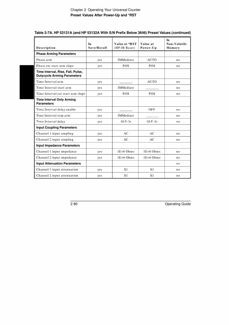
8/4/2019 53131 Operating Guide
http://slidepdf.com/reader/full/53131-operating-guide 156/196
2-80 Operating Guide
y ________
Time Interval ext star t a rm slope yes POS POS no
Time Interval Only Arming
Parameters
Time Interval delay enable yes ________ OFF no
Time Interval stop arm yes IMMedia te ________ no
Time In terval delay yes 10.E-3s 10.E-3s no
Input Coupling Parameters
Channel 1 input coupling yes AC AC no
Channel 2 input coupling yes AC AC no
Input Impedance ParametersChannel 1 inpu t impedance yes 1E+6 Ohms 1E+6 Ohms no
Channel 2 inpu t impedance yes 1E+6 Ohms 1E+6 Ohms no
Input Attenuation Parameters no
Channel 1 input at tenuat ion yes X1 X1 no
Channel 2 input at tenuat ion yes X1 X1 no
Chapter 2 Operating Your Universal Counter
Preset Values After Power-Up and *RST
2
Display Parameters
Display blank no disabled disabled no
Display mode (resu lt /menu) no result s results no
Trigger Level Parameters
Channel 1 t r igger level (volts) yes 0.000V1 0.000V1 no
Channel 2 t r igger level (volts) yes 0.000V1 0.000V1 no
Channel 1 tr igger level (percen t) yes 50% 50% no
Table 2-7A. HP 53131A (and HP 53132A With S/N Prefix Below 3646) Preset Values (continued)
Descript ion
In
Save/Recall
Value at *RST
(HP-IB Reset)
Value at
Power-Up
In
Non-Volatile
Memory

8/4/2019 53131 Operating Guide
http://slidepdf.com/reader/full/53131-operating-guide 157/196
Operating Guide 2-81
Channel 1 t r igger level (percen t) yes 50% 50% no
Channel 2 t r igger level (percen t) yes 50% 50% no
Trigger Slope Parameters
Channel 1 t r igger slope yes POS POS no
Channel 2 t r igger slope yes POS POS no
Sensitivity Parameters
Channel 1 sensit ivity yes 100% HIGH no
Channel 2 sensit ivity yes 100% HIGH no
Input Routing Parameters
Input route for Time Interval yes SEPARATE SEPARATE no
Measurement ControlParameters
Run/Single select ion yes SINGLE RUN 2 no
Math Operation Parameters
Math on/off yes OFF OFF no
Scale yes 1.000000 1.000000 no
Offset yes 0.0000000000 0.0000000000 no
Chapter 2 Operating Your Universal Counter
Preset Values After Power-Up and *RST
2
Limits Parameters
Limit t est on/off yes OFF OFF no
On fa il stop/go on yes GO ON GO ON no
Lower limit yes 0.0000000000 0.0000000000 no
Upper limit yes 0.0000000000 0.0000000000 no
Limit display number/graph yes NUMBER NUMBER no
Stats Parameters
Table 2-7A. HP 53131A (and HP 53132A With S/N Prefix Below 3646) Preset Values (continued)
Descript ion
In
Save/Recall
Value at *RST
(HP-IB Reset)
Value at
Power-Up
In
Non-Volatile
Memory

8/4/2019 53131 Operating Guide
http://slidepdf.com/reader/full/53131-operating-guide 158/196
2-82 Operating Guide
Stats Parameters
Stat s on/off yes OFF OFF no
Stat s measurement count , N yes 100 100 no
Display measurement /st a ts yes MEAS MEAS no
Stat s use all/in limits yes USE ALL USE ALL no
On-single measurement count yes 1 (AUTO OFF) 1 (AUTO OFF) no
Print Parameters
Pr int ing on/off yes OFF OFF no
Timebase Parameters
Timebase auto/in terna l/external yes AUTO AUTO no
Expected Frequency Parameters
Channel 1 expected frequency no ________3 ________3 no
Channel 2 expected frequency no ________3 ________3 no
Channel 3 expected frequency no ________3 ________3 no
Chapter 2 Operating Your Universal Counter
Preset Values After Power-Up and *RST
2
Auto-Frequency Parameters
Channel 1 auto-frequency on/off no ON ON no
Channel 2 auto-frequency on/off no ON ON no
Channel 3 auto-frequency on/off no ON ON no
Trigger Offset Cal Parameters
Channel 1 t r igger offset ca l no ________4 ________4 yes, (2048)
Channel 2 tr igger offset ca l no 4 4 yes, (2048)
Table 2-7A. HP 53131A (and HP 53132A With S/N Prefix Below 3646) Preset Values (continued)
Descript ion
In
Save/Recall
Value at *RST
(HP-IB Reset)
Value at
Power-Up
In
Non-Volatile
Memory

8/4/2019 53131 Operating Guide
http://slidepdf.com/reader/full/53131-operating-guide 159/196
Operating Guide 2-83
Channel 2 t r igger offset ca l no ________ ________ yes, (2048)
Trigger Gain Cal Parameters
Channel 1 t r igger ga in ca l no ________4 ________4 yes, (1700)
Channel 2 t r igger ga in ca l no ________4 ________4 yes, (1700)
Time Interval Offset CalParameters no ________4 ________4 yes, (2100)
Utility Menu Parameters
Option Timebase cal no ________4 ________4 yes, (2048)
HP-IB address no ________4 ________4 yes,(3)
Digit separa tor (radix) no ________
4
________
4yes,
(USA STYLE)Baud ra te, (RS-232) no ________4 ________4 yes, (9600)
Parity, (RS-232) no ________4 ________4 yes, (OFF )
Pacing, (RS-232) no ________4 ________4 yes, (XON)
DTR, (RS-232) no ________4 ________4 yes,
(DTR_HIGH)

8/4/2019 53131 Operating Guide
http://slidepdf.com/reader/full/53131-operating-guide 160/196
Chapter 2 Operating Your Universal Counter
Preset Values After Power-Up and *RST
2
HP 53132A (With S/N P refix 3646 and Above) Prese t
Values for Fun ct ions Accessible Via Front P ane l or
HP-IB
Table 2-7B lists preset values for th e HP 53132A (with serial num ber
prefix 3646 an d a bove).
Table 2-7B. HP 53132A (S/N 3646 and above) Preset Values
Descript ion
In
Save/Recall
Value at *RST
(HP-IB Reset)
Value at
Power-Up
In
Non-Volatile
Memory
Function-Select Parameters
Measurement funct ion yes FREQ1 FREQ1 no

8/4/2019 53131 Operating Guide
http://slidepdf.com/reader/full/53131-operating-guide 161/196
Operating Guide 2-85
Frequency, Period, and Ratio
Arming Parameters
Frequency arm yes ________ TIME no
Frequency star t arm yes IMMedia te ________ no
Frequency stop arm yes TIMer ________ no
Frequency stop a rm digits yes 4 4 no
Frequency gate t ime yes 100.E-3s 100.E-3s no
Frequency ext sta r t a rm slope yes POS POS no
Frequency ext stop arm yes ________ AUTO no
Totalize Arming Parameters
Tota lize arm yes ________ TIME no
Tota lize sta r t arm yes IMMedia te ________ no
Tota lize stop arm yes TIMer ________ no
Tota lize ga te t ime yes 100.E-3s 100.E-3s no
Tota lize ext st ar t a rm slope yes POS POS no
Tota lize ext stop arm yes ________ EDGE no
Chapter 2 Operating Your Universal Counter
Preset Values After Power-Up and *RST
2
Phase Arming Parameters
Phase arm yes IMMedia te AUTO no
Phase ext sta r t a rm slope yes POS POS no
Pulse, Rise, Fall, Dutycycle
Arming Parameters
Pulse Arming Parameters
Pulse st ar t a rm yes IMMedia te AUTO no
l l
Table 2-7B. HP 53132A (S/N 3646 and above) Preset Values (continued)
Descript ion
In
Save/Recall
Value at *RST
(HP-IB Reset)
Value at
Power-Up
In
Non-Volatile
Memory

8/4/2019 53131 Operating Guide
http://slidepdf.com/reader/full/53131-operating-guide 162/196
2-86 Operating Guide
Pulse ext sta r t a rm slope yes POS POS no
Time Interval Arming
Parameters
Time In terval sta r t a rm yes IMMedia te AUTO no
Time Interval ext star t a rm slope yes POS POS no
Time In terval sta r t a rm delay yes IMMedia te NONE no
Time Interval start arm delay
time
yes 100 E-9s 100 E-9s no
Time Interval start arm delay
events
yes 1 1 no
Time In terval stop a rm yes IMMedia te AUTO no
Time Interval ext stop arm slope yes POS POS no
Time In terval stop a rm delay yes IMMedia te NONE no
Time Interval stop ar m delay
time
yes 100 E-9s 100 E-9s no
Time Interval stop ar m delay
events
yes 1 1 no
Input Coupling Parameters
Channel 1 input coupling yes AC AC no
Channel 2 input coupling yes AC AC no
Chapter 2 Operating Your Universal Counter
Preset Values After Power-Up and *RST
2
Input Impedance Parameters
Channel 1 input impedance yes 1E+6 Ohms 1E+6 Ohms no
Channel 2 input impedance yes 1E+6 Ohms 1E+6 Ohms no
Input Attenuation Parameters no
Channel 1 input at tenuat ion yes X1 X1 no
Channel 2 input at tenuat ion yes X1 X1 no
Display Parameters
Table 2-7B. HP 53132A (S/N 3646 and above) Preset Values (continued)
Descript ion
In
Save/Recall
Value at *RST
(HP-IB Reset)
Value at
Power-Up
In
Non-Volatile
Memory

8/4/2019 53131 Operating Guide
http://slidepdf.com/reader/full/53131-operating-guide 163/196
Operating Guide 2-87
Display blank no disabled disabled no
Display mode (resu lt /menu) no result s results no
Trigger Level Parameters
Channel 1 t r igger level (volts) yes 0.000V1 0.000V1 no
Channel 2 t r igger level (volts) yes 0.000V1 0.000V1 no
Channel 1 t r igger level (percen t) yes 50% 50% no
Channel 2 t r igger level (percen t) yes 50% 50% no
Trigger Slope Parameters
Channel 1 t r igger slope yes POS POS no
Channel 2 t r igger slope yes POS POS no
Sensitivity Parameters
Channel 1 sensit ivity yes 100% HIGH no
Channel 2 sensit ivity yes 100% HIGH no
Input Routing Parameters
Input route for Time Interval yes SEPARATE SEPARATE noMeasurement ControlParameters
Run/Single select ion yes SINGLE RUN 2 no
Chapter 2 Operating Your Universal Counter
Preset Values After Power-Up and *RST
2
Math Operation Parameters
Math on/off yes OFF OFF no
Scale yes 1.000000 1.000000 no
Offset yes 0.0000000000 0.0000000000 no
Limits Parameters
Limit t est on/off yes OFF OFF no
On fa il stop/go on yes GO ON GO ON no
Table 2-7B. HP 53132A (S/N 3646 and above) Preset Values (continued)
Descript ion
In
Save/Recall
Value at *RST
(HP-IB Reset)
Value at
Power-Up
In
Non-Volatile
Memory
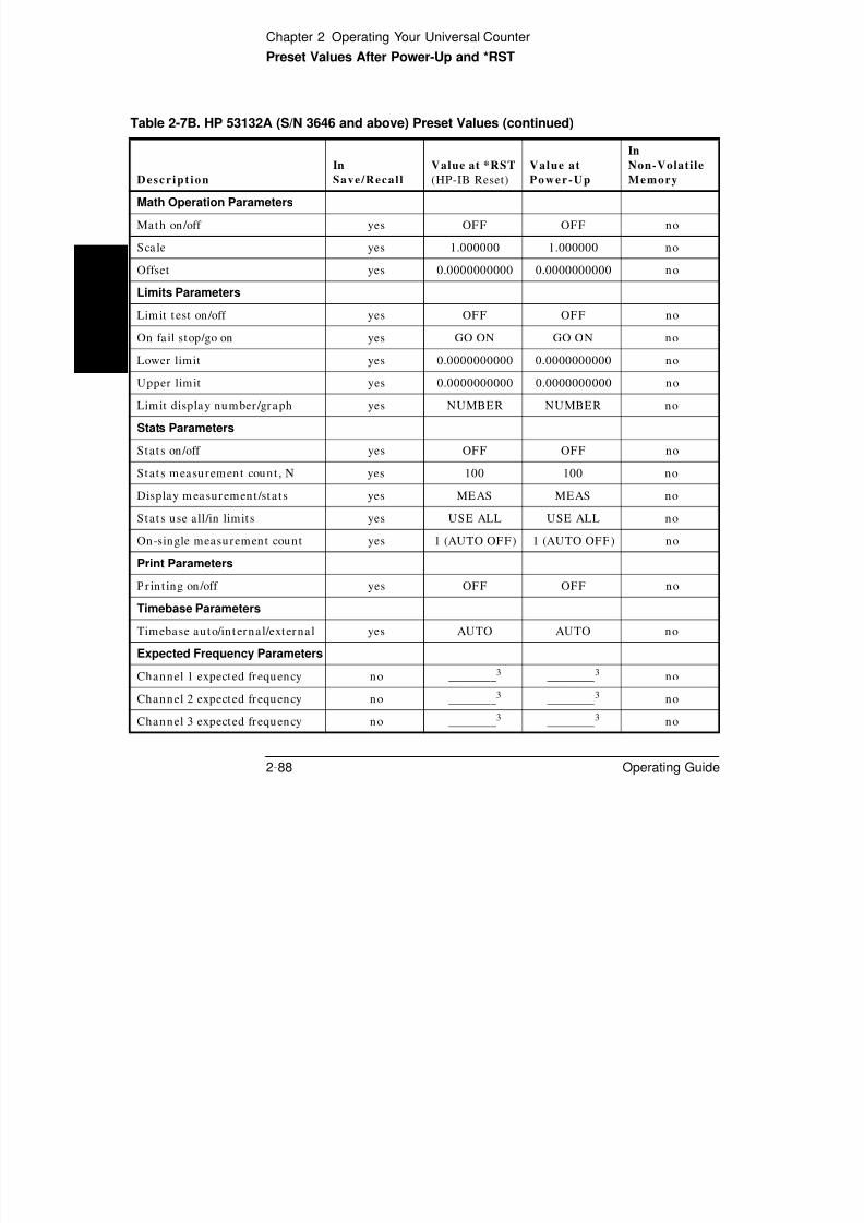
8/4/2019 53131 Operating Guide
http://slidepdf.com/reader/full/53131-operating-guide 164/196
2-88 Operating Guide
Lower limit yes 0.0000000000 0.0000000000 no
Upper limit yes 0.0000000000 0.0000000000 no
Limit display number/graph yes NUMBER NUMBER no
Stats Parameters
Stat s on/off yes OFF OFF no
Stat s measurement count , N yes 100 100 no
Display measurement /st a ts yes MEAS MEAS no
Stat s use all/in limits yes USE ALL USE ALL no
On-single measurement count yes 1 (AUTO OFF) 1 (AUTO OFF) no
Print Parameters
Pr int ing on/off yes OFF OFF no
Timebase Parameters
Timebase auto/in terna l/external yes AUTO AUTO no
Expected Frequency Parameters
Channel 1 expected frequency no ________3
________3
noChannel 2 expected frequency no ________3 ________3 no
Channel 3 expected frequency no ________3 ________3 no
Chapter 2 Operating Your Universal Counter
Preset Values After Power-Up and *RST
2
Auto-Frequency Parameters
Channel 1 auto-frequency on/off no ON ON no
Channel 2 auto-frequency on/off no ON ON no
Channel 3 auto-frequency on/off no ON ON no
Trigger Offset Cal Parameters
Channel 1 t r igger offset ca l no ________4 ________4 yes, (2048)
Channel 2 t r igger offset ca l no ________4 ________4 yes, (2048)
Table 2-7B. HP 53132A (S/N 3646 and above) Preset Values (continued)
Descript ion
In
Save/Recall
Value at *RST
(HP-IB Reset)
Value at
Power-Up
In
Non-Volatile
Memory

8/4/2019 53131 Operating Guide
http://slidepdf.com/reader/full/53131-operating-guide 165/196
Operating Guide 2-89
Trigger Gain Cal Parameters
Channel 1 t r igger ga in ca l no ________4 ________4 yes, (1700)
Channel 2 t r igger ga in ca l no ________4 ________4 yes, (1700)
Time Interval Offset CalParameters no ________4 ________4 yes, (2100)
Utility Menu Parameters
Option Timebase cal no ________4 ________4 yes, (2048)
HP-IB address no ________4 ________4 yes, (3)
Digit separa tor (radix) no ________4 ________4yes, (USA
STYLE)
Baud ra te, (RS-232) no ________4 ________4 yes, (9600)
Parity, (RS-232) no ________4 ________4 yes, (OFF )
Pacing, (RS-232) no ________4 ________4 yes, (XON)
DTR, (RS-232) no ________4 ________4yes,
(DTR_HIGH)
Chapter 2 Operating Your Universal Counter
Preset Values After Power-Up and *RST
2 1 At power-up, the trigger level is defaulted. The default value is shown in the table. The Counter retains thisvalue until the first auto-trigger cycle runs. Since the Counter powers up on Run mode with auto-trigger ON,the auto-trigger cycle runs almost immediately. The default value is overwritten by a measured result almostimmediately.
Calibration Security Parameters
Secure sta te no ________4 ________4 yes, (SECU RE)
Security code no ________4 ________4
yes, (53131 or
53132)
Calibra t ion count no ________4 ________4 yes, (0)
Table 2-7B. HP 53132A (S/N 3646 and above) Preset Values (continued)
Descript ion
In
Save/Recall
Value at *RST
(HP-IB Reset)
Value at
Power-Up
In
Non-Volatile
Memory

8/4/2019 53131 Operating Guide
http://slidepdf.com/reader/full/53131-operating-guide 166/196
2-90 Operating Guide
At *RST, the trigger level variable is defaulted. The default value is shown in the table. Same as for power-up,the Counter retains this value until the first auto-trigger cycle runs. However, on *RST, the Counter is set up inSingle mode, (not Run mode), with auto-trigger ON. The auto-trigger cycle runs only on initiation of ameasurement. The default value for the variable persists until overwritten by a measured result, but it may bea long time before you request a measurement; therefore, it may be a long time that the default valuepersists.
2 At power-up, you can bring up the Counter either in the Utility menu, or in the results display. The defaultbehavior of the Run/Single variable differs according to that choice.
When the Counter powers up in the result display, it powers up in Run mode and begins makingmeasurements immediately.
The Counter does not make measurements when the Utility menu is selected. (This is to reduce confusionwhile the user configures major attributes of the instrument.) When you power up on the Utility menu, theCounter is in Single. Upon exit of the Utility menu, the Counter transitions to Run automatically.
3 At *RST and at power-up, this value is undefined. The frequency-estimation routine, (“auto-frequency”routine), is enabled. When you select auto-frequency OFF, and provide a value, the variable takes on thatvalue.
4 Fundamental instrument settings are stored in non-volatile RAM. These settings persist even if the Counter ispowered down and back up again. They persist if the Counter is reset over HP-IB with *RST. You can changethese settings, and the changed value is stored so that it is unaffected if the Counter is powered down orreset over HP-IB with *RST.
The default values for these special features are indicated in the table. The default values are used whennew EPROMs are installed; they remain in effect until you overwrite them.
An example is the trigger calibration setting. Calibration values are defaulted until calibration is performed atthe factory. Another example is the RS-232 BAUD rate. BAUD rate is defaulted until you pick a different rate.
Chapter 2 Operating Your Universal Counter
Preset Values After Power-Up and *RST
2
Pres et Values for Fun ct ions Access ible Via HP -IB Only
Table 2-8. HP 53131A/132A Preset Values—Accessible Via HP-IB Only
Descript ion
In
Save/Recall
Value at *RST
(HP-IB Reset)
Value at
Power-Up
In
Non-Volatile
Memory
Arming Parameters
Frequency ext stop arm slope yes NEG NEG no
Tota lize ext stop arm slope yes NEG NEG no
Math, Limit Parameters
Math , limit -t est reca lcu late yes OFF ON no
Reset limit -test fail count on
INITi t ON ON

8/4/2019 53131 Operating Guide
http://slidepdf.com/reader/full/53131-operating-guide 167/196
Operating Guide 2-91
INITia te yes ON ON no
Statistics Parameters
Stat ist ics type yes MEAN MEAN no
Miscellaneous MeasurementParameters
Monitor external t imebase no TRUE TRUE no
Interpolator ca librat ion on/off no ON ON no
Status Reporting Parameters
Event sta tus enable no ________ 0 no
Service request enable no ________ 0 no
OSR enable no ________ 0 no
OSR negat ive t ransit ion filter no ________ 0 no
OSR posit ive t ransit ion filter no ________ 1809 no
QSR enable no ________ 0 no
QSR posit ive t ransit ion filter no ________ 18277 no
QSR negat ive t ransit ion filter no ________ 0 no
Error queue no ________ cleared no
Chapter 2 Operating Your Universal Counter
Preset Values After Power-Up and *RST
2
Miscellaneous HP-IB Parameters
Response format yes ASCii ASCii no
Device t r igger defin it ion yes INIT INIT no
Macros no disabled disabled no
CONFigure? response no ________ undefined no
READ, FETCh funct ion memory no ________ ________ no
Table 2-8. HP 53131A/132A Preset Values—Accessible Via HP-IB Only (continued)
Descript ion
In
Save/Recall
Value at *RST
(HP-IB Reset)
Value at
Power-Up
In
Non-Volatile
Memory

8/4/2019 53131 Operating Guide
http://slidepdf.com/reader/full/53131-operating-guide 168/196
2-92 Operating Guide
Chapter 2 Operating Your Universal Counter
Summary of the Measurement Sequence
2
Sum ma ry of th e Measu rement Sequence
Use Utility menu t o:
• choose the t imebase sou rce.
• configure the HP-IB if you intend to operate the Counter remotely.
• set RS-232 serial port if you intend for t he Counter to perform
print ing an d/or limit-detecting.
Use MEASURE menu keys to select t he mea sur ement fun ction.
Use CHANNELs 1 and 2 keys to set u p input conditioning.
Use Gate & ExtArm key to:

8/4/2019 53131 Operating Guide
http://slidepdf.com/reader/full/53131-operating-guide 169/196
Operating Guide 2-93
Use Gate & ExtArm key to:
• s et the ga te t ime and r esolu t ion .
• set a rming.
Use Sca le & Offset key to set up m at h opera tions.
Use Uppr & Low er key to set limits.
Use Limit Modes key to set u p limit testing.
Use Stats key to set up st at istics an d limit filter ing.
Use Save & Print key to enable or disable printing.
Use Run and Stop/Single keys to cont rol measur ement s.
Chapter 2 Operating Your Universal Counter
Common Questions
2
Comm on Quest ions
Why is Stats result not ava i lable ye t?
Your Count er ha s not completed N mea sur ement s yet.
Why w on’t printe r wo rk?
Go to the Ut ility menu an d set up ser ial port .
Why did Counte r stop measu ring?• Did you set the Counter to s top on l imits?
• Are a ll measu rements ou t side the limit s ?
8/4/2019 53131 Operating Guide
http://slidepdf.com/reader/full/53131-operating-guide 170/196
2-94 Operating Guide
Why did Counter go to i ts default state a fter I set up
my RS -232 port?
• Did you save your s tat e before you cycled power?• Did you restore your s tate after configuring the port?
Counter’s n ume ric display does not fol low the
num erical convention for my coun try.
• Go to the Utili ty menu and change the numerical convention to be
displayed (use th e SHOW 9 AS: menu item).
How d o I display the 13th digit in my num erical resu lt?
• Use the Offset fea ture. Inst ruct ions appear on page 2-31 and
page 2-32 in th e section titled “Using th e MATH Menu Keys.”
3

8/4/2019 53131 Operating Guide
http://slidepdf.com/reader/full/53131-operating-guide 171/196
Specifications

8/4/2019 53131 Operating Guide
http://slidepdf.com/reader/full/53131-operating-guide 172/196
Chapter 3 Specifications
Instrument Inputs (Continued)
Instrum ent Inputs (Continu ed)
Channel 3 Input Specifications4, 5 Channel 3 Input Characteristics
Frequency Range
Option 030 100 MHz to 3 GHzOption 050 200MHz to 5 GHzOption 124 200 MHz to 12.4 GHz
Power Range and Sensitivity (Sinusoid)
Option 030100 MHz to 2.7 GHz: –27 dBm to +19 dBm2.7 GHz to 3 GHz: –21 dBm to +13 dBm
Option 050200 MHz to 5 GHz: –23 dBm to +13 dBm
Option 124200 MHz to 12.4 GHz –23 dBm to +13 dBm
Damage Level:
Option 030 5 VrmsOption 050 +25 dBmOption 124 +25 dBm
Impedance: 50 Ω
Coupling: ACVSWR: < 2.5:1

8/4/2019 53131 Operating Guide
http://slidepdf.com/reader/full/53131-operating-guide 173/196
Operating Guide 3-3
3
4 Channel 3 is available as an option.
5 When ordered with optional rear terminals, the Channel 3 connector on the front panel for Option 030 will be routed to the rear panel (rearpanel only). There is no degradation in specifications for this input. Option 050 and Option 124 input connectors are available on the frontpanel only.
6 53131A—Applies to Serial Number Prefix 3710A and above.53132A—Applies to Serial Number Prefix 3546A and above.
Below these Serial Number Prefixes, the specification is :
High-level input: >3.0 VLow-level input: <1.5 V.
External Arm Input Specifications External Arm Input Characteristics
Signal Input Range:
TTL compatible6
Timing Restrictions:Pulse Width: > 50 nsTransition Time: < 250 nsStart- to-Stop Time: > 50 ns
Damage Level: 10 Vrms
Impedance: 1 kΩ
Input Capacitance: 17 pFStart Slope: Positive or NegativeStop Slope: Positive or Negative
Notes:
External Arm is available for all measurements except Peak Volts.
External Arm is referred to as External Gate for somemeasurements.
Chapter 3 Specifications
Time Base
Note that power to the time base is maintained when the counter is placed in standby via the front panel switch. The internal fan will continue tot d thi diti t i t i l t i t t li bilit
Time Bas e
Internal Time Base Stability
Standard(0° to 50°C)
Medium StabilityOven (Option 001)
High Stability Oven(Option 010)
Ultra High StabilityOven (Option 012)
Temperature Stability:
(referenced to 25°C) < 5 x 10 –6 < 2 x 10 –7 < 2.5 x 10 –9 < 2.5 x 10 –9
Aging Rate
(after 30 days)
Per Day:Per Month:Per Year:
< 3 x 10 –7< 4 x 10 –8
< 2 x 10 –7< 5 x 10 –10
< 1.5 x 10 –8< 1 x 10 –10
< 3 x 10 –9
< 2 x 10 –8
Turn-on stability vs. time:(in 30 minutes)
< 2 x 10
–7
(referenced to 2 hours) < 5 x 10
–9
(referenced to 24 hours) < 5 x 10
–9
(referenced to 24 hours)
Calibration: Manual Adjust Electronic Electronic Electronic

8/4/2019 53131 Operating Guide
http://slidepdf.com/reader/full/53131-operating-guide 174/196
3-4 Operating Guide
3
operate under this condition, to maintain long-term instrument reliability.
External Time Base Input Specifications External Time Base Input Characteristics
Voltage Range: 200 mVrms to 10 VrmsDamage Level: 10 Vrms Threshold: 0 VImpedance: 1 kΩInput Capacitance: 23 pFFrequency (53131A): 1 MHz, 5 MHz or 10 MHz
(automatic selection)Frequency (53132A): 10 MHz
Internal vs. External Time Base Selection:
Manual: Select Internal or ExternalAutomatic: Internal used when External not present
(default)
Time Base Output Specifications
Output Frequency: 10 MHzVoltage: > 1 Vpp into 50 Ω
(centered around 0 V)
Chapter 3 Specifications
Measurement Specifications
Measurement Specif icat ions
Frequency, Period
Channel 1 and 2 Range: 0.1 Hz to 225 MHz 4.44 ns to 10 s
Channel 3 Range:
Option 030 100 MHz to 3 GHz 0.33 ns to 10 nsOption 050 200 MHz to 5 GHz 0.2 ns to 5 nsOption 124 200 MHz to 12.4 GHz 80 ps to 5 ns
(Period 2 or 3 selectable only via the HP-IB interface)
For Automatic or External Arming:
(and signals < 100 Hz using Timed Arming)
For Time or Digits Arming:
LSD Displayed:
RMS Resolution:
LSD Displayed:
RMS Resolution:
t re s
Gate Time ----------------------------
Frequency
or Period
×2 2 t re s ×
Gate Time Number or Samples ×-------------------------------------------------------------------------------------------
t jit ter
Gate Time ----------------------------+
Frequency
or Period
×

8/4/2019 53131 Operating Guide
http://slidepdf.com/reader/full/53131-operating-guide 175/196
Operating Guide 3-5
3
The following graphs may also be used to compute errors for Period Measurements. To find the Period error (∆P), calculate the frequency of the
input signal ( ) and find the frequency error (∆F) from the chart. Then, calculate the period error as:
HP 53131A HP 53132Atres tres
typical 650 ps 200 pssee graphs for worst case resolution performance
For Automatic Arming:
where N = 1 for Ch1 or Ch2 Frequency < 1 MHz4 for Ch1 or Ch2 Frequency > 1 MHz128 for Ch3
HP 53131A HP 53132Atres t jitter tres t jitter
typical 500 ps 50 ps 225 ps 3 pssee graphs for worst case resolution performance
Number of Samples = Gate Time x Frequency (Frequency < 200 kHz)Gate Time x 200,000 (Frequency > 200 kHz)
Systematic Uncertainty:
HP 53131A HP 53132Atacc tacc
typical 350 ps 100 psworst case 1.25 ns 500 ps
Trigger: Default setting is Auto Trigger at 50%
Systematic Uncertainty:
HP 53131A HP 53132Atacc tacc
typical 100 ps 10 psworst case 300 ps 100 ps
Trigger: Default setting is Auto Trigger at 50%
t re s 2
2 Trigger Error 2 ×( )+
Gate Time ----------------------------------------------------------------------
Frequency
or Period
×
Gate Time N
Frequency ----------------------------=
4 t re s 2
2 Trigger Error 2 ×+×
Gate Time Number or Samples ×-------------------------------------------------------------------------------------------
t jit ter
Gate Time ----------------------------+
x Frequency
or Period
Time Base Error ±t ac c
Gate Time ----------------------±
Frequency
or Period
× Time Base Error ±t ac c
Gate Time ----------------------±
Frequency
or Period
×
F 1P ----= P ∆ F ∆F ------- P ×=
Chapter 3 Specifications
Measurement Specifications (Continued)
Measu remen t Specif icat ions (Continued)
HP 53131A—Worst Case RMS Resolution
Automatic or External Arming:
10 100 1000 10000 100000 1000000 1E+07 1E+08 1E+09 1E+101E-10
1E-8
1E-6
1E-4
1E-2
1E+00
1E+02
F r e q u e n c y E r r o r ( H z )
Auto Armed1ms
1s
10s
GateTime
10ms
100ms

8/4/2019 53131 Operating Guide
http://slidepdf.com/reader/full/53131-operating-guide 176/196
3-6 Operating Guide
3
Time or Digit Arming:
The preceding graphs do not reflect the effects of trigger error. To place an upper bound on the added effect of this error term, determine thefrequency error from the appropriate graph and add a trigger error term as follows:
Automatic or External Arming Time or Digit Arming
10 100 1000 10000 100000 1000000 1E+07 1E+08 1E+09 1E+10
Input Frequency (Hz)
10 100 1000 10000 100000 1000000 1E+07 1E+08 1E+09 1E+10
Input Frequency
1E-10
1E-8
1E-6
1E-4
1E-2
1E+00
1E+02
F r e q u e n c
y E r r o r ( H z )
1ms
GateTime
10ms
100ms
1s
10s
Frequency Error 2 Trigger Error ×
Gate Time -----------------------------------------------
+
Frequency or
Period × Frequency Error
4 2 × Trigger Error ×Gate Time Number of Samples ×-------------------------------------------------------------------------------------------
+
Frequency or
Period ×
Chapter 3 Specifications
Measurement Specifications (Continued)
HP 53132A—Worst Case RMS Resolution
Automatic or External Arming:
Meas ureme nt Specif icat ions (Continu ed)
Auto Armed1ms
10ms
100ms
1s
10s
GateTime
F r e q u e n c y
E r r o r ( H z )
1E-10
1E-8
1E-6
1E-4
1E-2
1E+00
1E+02

8/4/2019 53131 Operating Guide
http://slidepdf.com/reader/full/53131-operating-guide 177/196
Operating Guide 3-7
3 Time or Digit Arming:
The preceding graphs do not reflect the effects of trigger error. To place an upper bound on the added effect of this error term, determine thefrequency error from the appropriate graph and add a trigger error term as follows:
Time or Digit Arming Automatic or External Arming
10 100 1000 10000 100000
Input Frequency (Hz)
1000000 1E+07 1E+08 1E+09 1E+10
10 100 1000
1ms
10ms
100ms
1s
GateTime
10s
10000 100000
Input Frequency (Hz)
F r e q u e n
c y
E r r o r ( H z )
1000000 1E+07 1E+08 1E+09 1E+101E-10
1E-8
1E-6
1E-4
1E-2
1E+00
1E+02
Frequency Error 4 2 × Trigger Error ×
Gate Time Number of Samples ×-------------------------------------------------------------------------------------------
+
Frequency or
Period × Frequency Error
2 Trigger Error ×Gate Time
----------------------------------------------- +
Frequency or
Period ×
Chapter 3 Specifications
Measurement Specifications (Continued)
Frequency Measurement Example:
Given an HP 53132A with a High Stability Oven that was calibrated 3 days ago, measure a 15 MHz square wave signal (which has negligibletrigger error) with a 1 second gate time. Compute the measurement error to within 2-sigma confidence.
Measu remen t Specif icat ions (Continued)
Measurement Error Systematic Uncertainty 2 RMS Resolution ×±=
Time Base Error ±t ac c
Gate Time ----------------------------±
2 4 t re s
2 2 Trigger Error
2 ×( )+×
Gate Time Number of Samples ×-------------------------------------------------------------------------------------------
t jit ter
Gate Time ----------------------------+
×±
= Frequency ×
Number of Samples 200,000 since Frequency is greater than 200kHz and gate time equals 1 second =
Time Base Error Temperature Stability 3 Days Daily Aging Rate ×+=
2.5 10 9 –
3 5 10 10 –
×( )×+×=
4.0 10 9 –×=
Measurement Error 4.0 10 9 –×± 1 10
11–× s
1s ---------------------------±
2 4 225 10
12 –
s ×( )2
2 0 ×( )+×1s 200 000 ,×
-------------------------------------------------------------------------------3 10
12 –
s ×1s
---------------------------+
×±
15MHz ×=
4.0 ± 10 9 –× 2 2.01 10
12 –× 3 10 12 –×+( )×±( ) 15MHz ×=

8/4/2019 53131 Operating Guide
http://slidepdf.com/reader/full/53131-operating-guide 178/196
3-8 Operating Guide
3Which is to say that the HP 53132A would display results in the range 15 MHz ±60.2 mHz. Note however that the dominant error is the TimeBase Error. If an even higher stability time base is available or if the instrument can be source locked to the 15 MHz signal, then this error termcan be substantially reduced. The measurement resolution under these conditions is ±75 µHz (1 sigma) which determines the number of digitsdisplayed.
( )( )
4.0 ± 10 9 –× 1 10
11–×±( ) 15MHz ×=
60.2 mHz ±=
Chapter 3 Specifications
Measurement Specifications (Continued)
Time Interval
Measurement is specified over the full signal ranges7
of Channels 1 and 2.
Results Range: –1 ns to 105 s
LSD:
RMS Resolution:
tres
Systematic Uncertainty: ±(Time Base Error × TI) ± Trigger Level Timing Error ± 1.5 ns Differential Channel Error (HP 53131A)± 900 ps Differential Channel Error (HP 53132A)
Time Interval Delay
After a Time Interval Measurement has begun by satisfying the trigger conditions on Channel 1, the instrument will wait for theuser-entered delay time to elapse before the end-of-measurement trigger will be accepted on Channel 2. Please refer to MeasurementArming for additional information.
Meas ureme nt Specif icat ions (Continu ed)
53131A 53132A500 ps 150 ps--------------------------------------------------------------------------------------------
t re s 2
Start Trigger Error 2
Stop Trigger Error 2
+ +
53131A 53132A750 ps 300 ps--------------------------------------------------------------------------------------------

8/4/2019 53131 Operating Guide
http://slidepdf.com/reader/full/53131-operating-guide 179/196
Operating Guide 3-9
3
Frequency Ratio:
Measurement is specified over the full signal range of each input.Results Range: 10 –10 to 1011
‘Auto’ Gate Time: 100 ms (or sufficient cycles on Channel 2 or 3 to make a valid measurement, whichever is longer)
LSD:
RMS Resolution:
To minimize relative phase measurement error, connect the higher frequency signal to Channel 1 when possible.
7
See Specifications for Pulse Width and Rise/Fall Time measurements for additional restrictions on signal timing characteristics.
Ch 1Ch 2 ⁄ Ch 1
Ch 3 ⁄ Ch 2 Ch 1 ⁄ Ch 3
Ch 1 ⁄
Ratio 12 ⁄ : 1
Ch2 Freq Gate Time ×----------------------------------------------------------- Ratio 13 ⁄ :
1
Ch3 Freq Gate Time ×-----------------------------------------------------------
Ratio 2 1 ⁄ :
Ch2 Freq
Ch1 Freq ( )2 Gate Time ×
------------------------------------------------------------------ Ratio 3 1 ⁄ :
Ch3 Freq
Ch1 Freq ( )2 Gate Time ×
------------------------------------------------------------------
Ratio 12 ⁄ : 2 1 Ch1 Freq Ch2 Trigger Error ×( )2
+×Ch2 Freq Gate Time ×
------------------------------------------------------------------------------------------------------------- Ratio 13 ⁄ : 2 1 Ch1 Freq Ch3 Trigger Error ×( )2
+×Ch3 Freq Gate Time ×
-------------------------------------------------------------------------------------------------------------
Ratio 2 1 ⁄ :
2 Ch2 Freq 1 Ch1 Freq Ch2 Trigger Error ×( )2 +××
Ch1 Freq ( )2 Gate Time ×
-------------------------------------------------------------------------------------------------------------------------------------------- Ratio 3 1 ⁄ :
2 Ch3 Freq × 1 Ch1 Freq Ch3 Trigger Error ×( )2 +×
Ch1 Freq ( )2 Gate Time ×
--------------------------------------------------------------------------------------------------------------------------------------------
Chapter 3 Specifications
Measurement Specifications (Continued)
Pulse Width
Measurement is specified over the full signal range of Channel 1. The width of the opposing pulse must be greater than 4 ns (e.g., whenmeasuring the positive pulse width, the negative pulse width must be greater than 4 ns).Pulse Selection: Positive or NegativeTrigger: Default setting is Auto Trigger8 at 50%Results Range: 5 ns to 105 s
LSD:
RMS Resolution:
tresSystematic Uncertainty:
± (Time Base Error × Pulse Width) ± Trigger Level Timing Error ±1.5 ns Differential Channel Error (HP 53131A)± 900 ps Differential Channel Error (HP 53132A)
Rise/Fall Time
Measurement is specified over the full signal ranges of Channel 1 The interval between the end of one edge and start of a similar edge
Measu remen t Specif icat ions (Continued)
53131A 53132A
500 ps 150 ps--------------------------------------------------------------------------------------------
t re s 2
Start Trigger Error 2
Stop Trigger Error 2
+ +
53131A 53132A
750 ps 300 ps--------------------------------------------------------------------------------------------

8/4/2019 53131 Operating Guide
http://slidepdf.com/reader/full/53131-operating-guide 180/196
3-10 Operating Guide
3
Measurement is specified over the full signal ranges of Channel 1. The interval between the end of one edge and start of a similar edgemust be greater than 4 ns. (e.g., when measuring a rising edge, 4 ns must elapse between the 90% point of one rising edge and the10% point of the next rising edge).Edge Selection: Positive or NegativeTrigger: Default setting is Auto Trigger8 at 10% and 90%Results Range: 5 ns to 105 s
LSD:
RMS Resolution:
tres
Systematic Uncertainty:± (Time Base Error × Transition Time) ± Trigger Level Timing Error ±1.5 ns Differential Channel Error (HP 53131A)
± 900 ps Differential Channel Error (HP 53132A)
Phase
Measurement is specified over the full signal range of Channels 1 and 2.Results Range: –180° to +360°
RMS Resolution:
tres
Systematic Uncertainty: (± Trigger Level Timing Error ± 1.5 ns Differential Channel Error) × Frequency (HP 53131A)(± Trigger Level Timing Error ± 900 ps Differential Channel Error) × Frequency (HP 53132A)
8 Restrictions noted on page 3-2 for Auto Trigger apply to the proper operation of these measurements. The Peak Volts measurement is used todetermine the signal amplitude and inaccuracies from this, noted on page 3-11, should be included in calculating the Trigger Level Timing Error.
53131A 53132A
500 ps 150 ps--------------------------------------------------------------------------------------------
t re s 2
Start Trigger Error 2
Stop Trigger Error 2
+ +
53131A 53132A750 ps 300 ps--------------------------------------------------------------------------------------------
t re s 2
2 Trigger Error 2 ×( )+( ) 1
Phase
360 °-----------------
2
+ × Frequency 360 °××
53131A 53132A750 ps 300 ps--------------------------------------------------------------------------------------------
Chapter 3 Specifications
Measurement Specifications (Continued)
Duty Cycle
Measurement is specified over the full signal range of Channel 1. However, both the positive and negative pulse widths must be greaterthan 4 ns.Results Range: 0 to 1 (e.g. 50% duty cycle would be displayed as .5)
RMS Resolution:
tres
Totalize
Measurement is specified over the full signal range of Channel 1.Results Range: 0 to 1015 Resolution: ± 1 count
Peak Volts
Measurement is specified on Channels 1 and 2 for DC signals; or for AC signals of frequencies between 100 Hz and 30 MHz with peak-to-k lit d t th 100 V (Th t ill ti t t t 225 MH th h lt f i di ti l )
Meas ureme nt Specif icat ions (Continu ed)
t re s 2
2 Trigger Error 2 ×( )+( ) 1 Duty Cycle
2 +( )× Frequency ×
53131A 53132A750 ps 300 ps--------------------------------------------------------------------------------------------

8/4/2019 53131 Operating Guide
http://slidepdf.com/reader/full/53131-operating-guide 181/196
Operating Guide 3-11
3
peak amplitude greater than 100 mV. (The measurement will continue to operate up to 225 MHz, though results are for indication only.)Results Range: –5.1 V to +5.1 VResolution: 10 mV
Systematic Uncertainty for AC signals: 25 mV + 10% of Vfor DC signals: 25 mV + 2% of V
Use of the input attenuator multiplies all voltage specifications (input range, results range, resolution and systematic uncertainty) by anominal factor of 10. For example with AC signals, the Systematic Uncertainty becomes: 250 mV + 10% of V.
Chapter 3 Specifications
Measurement Definitions
Measurement Def init ions
Definitions of Systematic Uncertainty Terms
• Trigger Error
External source and input amplifier noise may advance or delay the trigger points that define the beginning and end of a measurement.The resulting timing uncertainty is a function of the slew rate of the signal and the amplitude of spurious noise spikes (relative to the inputhysteresis band).
The (rms) trigger error associated with a single trigger point is:
where
E input = RMS noise of the input amplifier: 1 mVrms (350 µVrms typical). Note that the internal measurement algorithms significantlyreduce the contribution of this term.
E signal = RMS noise of the input signal over a 225 MHz bandwidth (100 kHz bandwidth when the low-pass filter is enabled). Note thatthe filter may substantially degrade the signal’s slew rate at the input of the trigger comparator.
For two-trigger-point measurements (e.g. Rise Time, Pulse Width), the Trigger Errors will be referred to independently as Start Trigger Errorand Stop Trigger Error.
Trigger ErrorE input ( )2
E signal ( )2 +
Input Signal Slew Rate at Trigger Point -------------------------------------------------------------------------------------------------------(in seconds)=

8/4/2019 53131 Operating Guide
http://slidepdf.com/reader/full/53131-operating-guide 182/196
3-12 Operating Guide
3
p gg
• Trigger Level Timing Error
Trigger level timing error results from a deviation of the actual trigger level from the specified (indicated) level. The magnitude of themeasurement timing error depends on several factors, primarily: resolution and accuracy of the trigger level circuit, fidelity of the inputamplifier, slew rate of the input signal at the trigger point, and width of the input hysteresis band (see illustration).
Trigger level timing error is associated with Time Interval, Pulse Width, Rise Time, Fall Time, Phase, and Duty Cycle measurements.The following equations define the general interpretation of its component error terms for a measurement. These should be summedtogether to obtain the overall Trigger Level Timing Error.
Upper Hystersis Limit
Trigger Level Setting
Lower Hystersis Limit
Actual Trigger Point:
Slope
Trigger Level Timing Errors
0.5 Hysteresis Band
0.5 Hysteresis Band
Amplitude
Time
Actual Trigger Point:
Slope
Input Hysteresis:0.5 Hysteresis Band ×
Input Signal Slew Rate at Start Trigger Point ---------------------------------------------------------------------------------------------------------------------
0.5 Hysteresis Band ×Input Signal Slew Rate at Stop Trigger Point ---------------------------------------------------------------------------------------------------------------------–
Trigger Level Setting:15 mV 1% Start Trigger Level Setting ×( )±
Input Signal Slew Rate at Start Trigger Point ---------------------------------------------------------------------------------------------------------------------
15 mV 1% Stop Tr igger Level Setting ×( )±Input Signal Slew Rate at Stop Trigger Point ---------------------------------------------------------------------------------------------------------------------±±
Chapter 3 Specifications
Measurement Definitions (Continued)
Measu remen t Definit ions (Continu ed)
• Fractional Time Base Error
Time base error is the maximum fractional frequency variation of the time base due to aging or fluctuations in ambient temperature or line
voltage:
Multiply this quantity by the measurement result to yield the absolute error for that measurement. Averaging measurements will not reduce(fractional) time base error. The HP 53131A/132A universal counters exhibit negligible sensitivity to line voltage; consequently this termmay be ignored.
• Differential Channel Error
The Differential Channel Error term included in many of the Systematic Uncertainty equations accounts for channel-to-channel mismatchand internal noise. This error can be substantially reduced by performing the TI Calibration in the temperature environment in which future
measurements are to be made and by careful measurement technique. Calibration is accessible via the Calibration Menu during power-up.
Typical Versus Worst Case Specifications
Specifications identified as “Typical” represent performance of the instrument that the majority of users will perceive under a wide variety ofconditions and signals. The specifications identified as “Worst Case” should be used when the instrument is under extreme environmentalconditions or when the accuracy of the measurement results are critically important.
Time Base Errorf ∆
f -----
aging rate
f ∆f
----- temperature
f ∆f
----- line voltage
+ + =

8/4/2019 53131 Operating Guide
http://slidepdf.com/reader/full/53131-operating-guide 183/196
Operating Guide 3-13
3
Time Interval Measurement LSD Definition
For the Time Interval, Pulse Width, and Rise/Fall Time measurements, the LSD is the measurement quantization error. “ tres” is the LSDplus the effects of certain internal error producing sources.
Additional Considerations for Digits and Time Arming Modes
For sample rates defined below, resolution will be reduced by up to 1 decade. The instruments display detects this condition and displays areduced-resolution result. Resolution is reduced in a band about f s, such that
where x is any integer, and y is any fraction in the set:
The width of the band is at most:
The value of fs is not available to the user, but the instrument can be queried over HP-IB to determine if this condition exists.
After the measurement completes, use the query :DIAGnostic:MEASure:PRESolution? The response is an ASCII text formatted string “Ø”for normal resolution and “1” for reduced resolution. This command is valid only when making frequency measurements in time or digitsarming and the input frequency is greater than 100 Hz.
x.y 10MHz
f s
-------------------= For Example:
25.25 10MHz 396 039.6 ,----------------------------=
x 25 =
y 0.25 1
4 ⁄ = =
0 1
2,1
3,2
3 ,1
4 ,2
4 ,3
4 ,1
5,2
5 ,3
5 ,4
5 , ... ⁄ ⁄ ⁄ ⁄ ⁄ ⁄ ⁄ ⁄ ⁄ ⁄ ,
6 107–× finput×
Gate Time--------------------------------------±
Chapter 3 Specifications
Measurement Arming and Processing
Measureme nt Arming and Process ing
Gate Time
Auto Mode, or 1 ms to 1000 s
Measurement Throughput
HP-IB ASCII: 200 Measurements/s (maximum)
(See examples in the Programming Guide for ways to optimizemeasurement throughput)
Measurement Arming
Start Measurement: Free Run, Manual, or ExternalStop Measurement: Continuous, Single, External, or TimedArming Modes:(Note that not all arming modes are available for every measurement function.)
Auto Arming: Measurements are initiated immediately and acquired as fast as possible, using a minimum number of signal
edges. Auto arming offers the highest measurement throughput, though measurement resolution may bereduced.Timed Arming: The duration of the measurement is internally timed to a user-specified value (also known as the “gate time”).
This mode should be used when the length of the measurement time must be controlled.Digits Arming: Measurements are performed to the requested resolution (number of digits) through automatic selection of the
acquisition time. This is the most convenient mode for when a specific measurement resolution is desired.External Arming: An edge on the External Arm Input enables the start of each measurement. Depending on the measurement
function, Auto Arming, Timed arming modes or another edge on the External Arm Input may be used to complete

8/4/2019 53131 Operating Guide
http://slidepdf.com/reader/full/53131-operating-guide 184/196
3-14 Operating Guide
3
function, Auto Arming, Timed arming modes or another edge on the External Arm Input may be used to completethe measurement.
Time Interval
Arming Modes: HP 53131ATime Interval Stop Delay Arming: The Stop Measurement condition on Channel 2 is inhibited (trigger hold-off) fora user specified time following the Start Measurement on Channel 1.
Time Interval Delay Range: 100 µs to 10 s*Time Interval Delay Resolution: 10 µs from 100 µs to 100 ms
1 ms from 100 ms to 10 sHP 53132ATime Interval Start Delay Arming: The start of a Time Interval measurement is delayed for a user-specifiedamount of time, or number of Channel 2 events, from the Start External Arming edge.
Start Delay TimeRange: 100 ns to 999.9999 ms
Start Delay Time Resolution: 100 nsStart Delay Event Range: 1 to 99,999,999 Channel 2 eventsStart Delay Event Rate: 5 MHz maximumStart Delay Event Setup Time: 30 ns minimum
Time Interval Stop Delay Arming: The Stop Measurement condition on Channel 2 is inhibited (trigger hold-off) fora user-specified amount of time, or number of Channel 2 stop events, following the Start Measurement onChannel 1, or, if enabled, the Stop External Arming edge.
Stop Delay Time Range: 100 ns to 10 s**Stop Delay Time Resolution: 100 ns from 100 ns to 1 s
1 ms from 1 s to 10 sStop Delay Event Range: 1 to 99,999,999 Channel 2 eventsStop Delay Event Rate: 5 MHz maximumStop Delay Event Setup Time: 30 ns minimum
* For firmware revisions below 3427 the valid range of delay is 1 ms to 10 s.** For firmware revisions below 3646 the valid range of delay is 1 ms to 10 s.
Chapter 3 Specifications
Measurement Arming and Processing (Continued)
Measu remen t Arming and Process ing (Continued )
Measurement Statistics
Available Statistics: Mean, Minimum, Maximum, Standard Deviation
Number of Measurements: 2 to 1,000,000. Statistics may be collected on all measurements or on only those which are between the limitbands. When the Limits function is used in conjunction with Statistics, N (number of measurements) refers to thenumber of in-limit measurements. In general, measurement resolution will improve in proportion to , up to thenumerical processing limits of the instrument.
Measurements: Statistics may be collected for all measurements except Peak Volts and Totalize.
Measurement Limits
Limit Checking: The measurement value is checked against user-specified limits at the end of each measurement.
Display Modes: The measurement result may be displayed as either the traditional numeric value or graphically as an asteriskmoving between two vertical bars. These bars define the upper and lower limits, and the asterisk represents thecurrent measurement result relative to these limits.
Out-of-Limits Indication: The out-of-limits condition can be indicated by any of the following methods:
• The limits annunciator will light on the front panel display.
• The instrument will generate an SRQ if enabled via HP-IB.
Th li i h d i l id d i h RS 232 ill l f h d i f h f li i
N

8/4/2019 53131 Operating Guide
http://slidepdf.com/reader/full/53131-operating-guide 185/196
Operating Guide 3-15
3
• The limits hardware signal provided via the RS-232 connector will go low for the duration of the out-of-limitcondition (see the description of this connector under the General Information section of this specificationstable).
• If the Analog Display mode is enabled, the asterisk appears outside the vertical bars, which define the upperand lower limits.
Chapter 3 Specifications
General Information
General Information
Save and Recall: Up to 20 complete instrument setups may be saved and recalled later. These setups are retained whenpower is removed from the universal counter.
Rack Dimensions (HxWxD): 88.5 mm x 212.6 mm x 348.3 mmWeight: 3.5 kg maximum
AC Line Supply DC Supply (Option 002 Only)
Power Supply Voltage: 100 to 120 VAC ±10% - 50, 60 or 400 Hz ±10% 10 to 32 VDC, 3-pin male XLR connector220 to 240 VAC ±10% - 50 or 60 Hz ±10%AC Line Voltage Se lection: Automatic Option 002 may not be ordered with Option 060
Power Requirements: 170 VA maximum (30 W typical) 4A initial inrush at 10 VDC3A max, once stabilized
Operating Environment: 0° C to 55° C
Storage Environment: –40° C to 71° C
Remote Interface: HP-IB (IEEE 488.1-1987, IEEE 488.2-1987)
HP-IB Interface Capabilities: SH1, AH1, T5, TE0, L4, LE0, SR1, RL1, PP0, DC1, DT1, C0, E2
Remote Programming Language: SCPI-1992.0 (Standard Commands for Programmable Instruments)
Safety: Designed in compliance with IEC 1010-1, UL 3111-1 (draft), CAN/CSA 1010.1
EMC: CISPR-11, EN50082-1, IEC 801-2, -3, -4
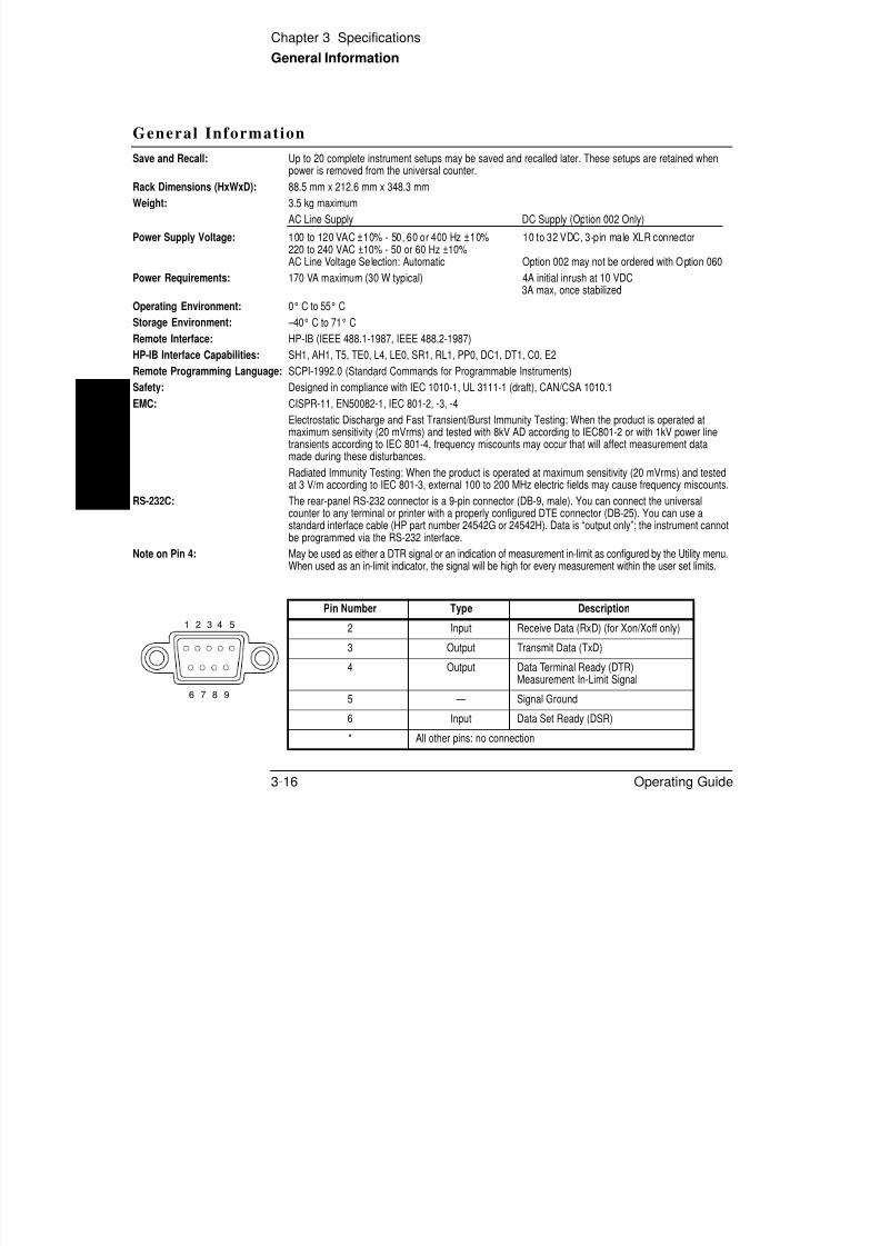
8/4/2019 53131 Operating Guide
http://slidepdf.com/reader/full/53131-operating-guide 186/196
3-16 Operating Guide
3
C S , 5008 , C 80 , 3,
Electrostatic Discharge and Fast Transient/Burst Immunity Testing: When the product is operated atmaximum sensitivity (20 mVrms) and tested with 8kV AD according to IEC801-2 or with 1kV power line
transients according to IEC 801-4, frequency miscounts may occur that will affect measurement datamade during these disturbances.
Radiated Immunity Testing: When the product is operated at maximum sensitivity (20 mVrms) and testedat 3 V/m according to IEC 801-3, external 100 to 200 MHz electric fields may cause frequency miscounts.
RS-232C: The rear-panel RS-232 connector is a 9-pin connector (DB-9, male). You can connect the universalcounter to any terminal or printer with a properly configured DTE connector (DB-25). You can use astandard interface cable (HP part number 24542G or 24542H). Data is “output only”; the instrument cannotbe programmed via the RS-232 interface.
Note on Pin 4: May be used as either a DTR signal or an indication of measurement in-limit as configured by the Utility menu.When used as an in-limit indicator, the signal will be high for every measurement within the user set limits.
Pin Number Type Description
2 Input Receive Data (RxD) (for Xon/Xoff only)
3 Output Transmit Data (TxD)
4 Output Data Terminal Ready (DTR)Measurement In-Limit Signal
5 — Signal Ground6 Input Data Set Ready (DSR)
* All other pins: no connection
1 2 3 4 5
6 7 8 9
Index
SYMBOLS
+/- key, 1-18, 2-8
NUMERICS10 MHz Output connector , 1-11
100 kHz Filter key, 2-44
50W/1 MW key, 1-16, 2-44
Aabort , 2-5
ac line selection , 1-11accessories
available, xix
supplied, xix
addr essed (talk/listen), 2-58
adjusting trigger level, 2-48
annunciators, front panel, 1-9
cha nging th e nu merical convent ion of
the display, 2-65cha nging th e slope, 2-49
cha nging tr igger m ode, 1-17
characters
*, 1-10
X, 1-10
choosing HIGH t o disable har dware
pacing., 2-62
choosing HW PACE , 2-62
choosing the timebase source , 2-59
COMMON 1
ON , 2-45
common questions , 2-94
computing Sta ts on filtered dat a
only, 1-32
fi i th RS 232 f di

8/4/2019 53131 Operating Guide
http://slidepdf.com/reader/full/53131-operating-guide 187/196
Operating Guide Index-1
p
ar ming modes
auto, xvi , 2-16
digits , xvi , 2-17external, xvi , 2-17
time, xvi, 2-17
ar row keys
entry/select keys , 2-8
auto arming, 2-16
auto triggering, 2-48
available options , xviii
Bbaud rate, 2-62
CCAL SECU RE , 2-71
CAL UNSECURE , 2-68, 2-71
calibration , 2-67
count , 2-72
Help menu , 2-72
initiate, 2-69new secur ity code , 2-72
unsecure, 2-68
Calibration menu , 1-8 , 2-67
configurin g th e RS-232 for sendin g
limit-detect outpu t , 2-64
connecting to a pr inter via HP-IB, 2-66connecting to a serial print er via th e
RS-232 port , 2-65
controlling measu rement , 1-36
counter description , xvi
coupling, 2-51
Ddata entry keys
num eric entry , 2-8DC/AC key, 1-15, 2-44
definition of sensit ivity, 2-46
description of
display annunciators , 1-9
entry/select (arrow) keys, 2-8
Gate & ExtArm Menu key, 2-16
inpu t condit ionin g toggle keys, 2-51
LIMITS keys
Limit Modes , 2-37Uppr&Lower , 2-37
Local key, 1-4
MATH keys
Index
Scale & Offset key, 2-27
Stats , 2-32
MEASURE keys
Fr eq & Ratio, 2-10
Other Meas , 2-10Time & Per iod, 2-10
Print menu , 2-56
Recall men u , 2-52
Remote indicator , 1-4
Run key, 2-5
Save menu , 2-52
scale an d offset , 1-19
self-test routines , 2-59
special char acter, display, 1-10Stop/Single key, 2-5
Trigger/Sensitivity men u key, 2-44
Utility menu , 2-57
description of count er , xvi
differences between firmware
revisions, xx
duty cycle , 2-14
EEnter key, 2-8
enter ing numer ic values, 2-8
entering offset value, 1-21
enter ing scale value , 1-20
entry/select keys
ar row keys, 2-8
equation
scale and offset , 1-19
examp le procedur e for
cha nging th e nu mber of digits of
resolution , 2-25computing Stats, 2-33
easy viewing of Stat s , 2-34
filtering dat a (using limits) dur ing
Sta ts, 2-35
Gate and Externa l Arm , 2-24
Offset function , 2-29

8/4/2019 53131 Operating Guide
http://slidepdf.com/reader/full/53131-operating-guide 188/196
Index-2 Operating Guide
,
digits arming, 2-17
digits, displaying more , 2-94
digits, thirteenth , 2-94
disabling Limit Testing, 1-30
disabling Mat h , 1-22
display
menu messages , 2-75
messages, 2-73
numerical convention
oth er coun tr ies, 2-65
USA, 2-65power-up/self test messages , 2-74
SHOW
GRAPH , 2-40
NUMBER, 2-41
display annunciators , 1-9
display special cha ra cter , 1-10
display th irteent h digit , 2-94
displaying Math r esults , 1-22
displaying Sta ts after filtering dat a of input signal, 1-34
DTR (Data Termina l Ready)
menu , 2-62
ru nn ing the self test , 2-61
Scale function , 2-28
setting t he Offset from the la stmeasurement value, 2-31
setting tr igger voltage an d
sensit ivity levels, 2-48
tu rn ing off Math mode, 2-30
tu rn ing off Sta ts m ode, 2-36
using th e Comm on 1 function t o
make time interval
measurements , 2-51
Example P rocedure for Turn ing Off
Math Mode, 2-30
Ext Arm conn ector , 2-17, 2-18, 2-20,
2-24
Extern al Arm inpu t connector, 1-11
external ar ming, 2-16 , 2-17
Extern al Reference Input
connector , 1-11
Ffalltime , 2-13
fan , 1-2 , 1-11
Featu res and Fun ctions
Index
Recall, 2-52
Save, 2-52
sensitivity, 2-46, 2-47
Unsave, 2-55
fine t ime inter val calibrat ion , 2-69firmwar e revisions, xx
Fr eq & Rat io key, 2-10
frequency, 2-11
frequency ra tio, 2-12
front -panel indicat ors , 1-3 , 1-4
front -panel menus , 1-5 , 1-6 , 1-7 , 1-8
function
duty cycle, 2-14
fall time, 2-13frequency, 2-11
frequency ra tio, 2-12
period, 2-13
phase, 2-15
pulse width s , 2-14
rise time, 2-13
Iimpedance, 2-51
in case of trouble , 2-94
indicators (LEDs), 1-3 , 1-4
initiating measur ements , 2-5input calibrat ion , 2-69
input conditioning keys , 2-44
input impedance, 2-51
LLegend , 1-13
Limit testing, 2-38
Limit-detect outpu t , 2-43, 2-64
Limit-Detect Outpu t connector, 1-11Limits Testing Example 1—Flag and
Stop Measuring On Limits , 2-38
Limits Testing Exa mple 2—Flag On
Limits but Continue Measuring, 2-40
Limits Test ing Exam ple 3—Use Analog
Graph Display While Adjusting Inpu t

8/4/2019 53131 Operating Guide
http://slidepdf.com/reader/full/53131-operating-guide 189/196
Operating Guide Index-3
time interval, 2-13
totalize , 2-14
voltage peaks , 2-15
GGate, 2-16
Gate and E xternal Arming menu , 2-16
auto, 2-16
digits , 2-17
external, 2-17
time, 2-17
Gate t ime and r esolution, 2-17
Hhardwar e pacing, 2-62
how to make measur ements , 1-12
how to set limits , 1-23
HP-IB Address , 2-58
HP -IB conn ect or, 1-11
HP-IB messages , 2-77
HPI B to ta lk-only, 2-66
hysteresis , 2-46
Signal, 2-40
Limits Testin g Exam ple 4—Selecting
Filtering Conditions of Stat s
Computation , 2-42
Limits Testing Exam ple 5—Sending
th e Limit-Detect Out put , 2-43
list of options , xviii
Local key, 1-4 , 2-75
low pa ss filter , 2-51
Mmaking a single measurement , 1-36
making repetitive measurement s , 1-36
mak ing the Counter flag on limits but
continue measuring when the signal
exceeds the u ser-entered limits , 1-28
Math
offset , 2-27
scale, 2-27
Math menu , 2-27MEASURE keys
Fr eq & Ratio, 2-10
Other & Meas , 2-10
Time & Per iod, 2-10
Index
measu remen t cont rol keys, 2-5
Run key, 2-5
Stop/Single key, 2-5
measurement function menus , 2-10
measurement sequence, 2-93measu ring du ty cycle, 2-14
measuring falltime, 2-13
measu ring frequency, 2-11
measu ring frequency ra tio, 2-12
measu ring period, 2-13
measuring phase, 2-15
measu ring positive/negat ive pulse
widths , 2-14
measuring positive/negative voltagepeaks, 2-15
measuring r isetime, 2-13
measuring time interval, 2-13
common , 2-51
measu ring, totalize, 2-14
menu messages , 2-75
modifying input trigger level, 1-17
Nnew security code ent ry, 2-72
num eric entr y for a m enu item , 2-4
numerical convention , 2-65
Ooffset , 1-19, 2-27
ON SINGLE menu item , 2-6
options, xviii
oscillat or adjust potentiometer , 1-11
Other Meas key, 2-10
Ppace
software, 2-63
pacing, 2-62
parity, 2-63
parity type, 2-62
peaks, 2-15

8/4/2019 53131 Operating Guide
http://slidepdf.com/reader/full/53131-operating-guide 190/196
Index-4 Operating Guide
menu s of
100kHz Filter key, 1-6
50 Ohm/1M Ohm key, 1-6
Calibra tion (Scale & Offset) key, 1-8
DC/AC key, 1-6
Fr eq & Rat io key, 1-5
Gate & ExtArm key, 1-5
Limit Modes key, 1-5
Other Meas key, 1-5
Recall k ey, 1-6
Save & Print key, 1-6Scale & Offset key, 1-5
Stats key, 1-5
Time & Period key, 1-5
Trigger/Sensitivity key, 1-6
Uppr & Lower key, 1-5
Utility key, 1-7
X10 Att enua te key, 1-6
messages
front panel, 2-73HP-IB, 2-77
menu , 2-75
power-up/self-test, 2-74
perform ing st at istics on
measurements , 1-31
period, 2-13
phase , 2-15
preface, xi
preset value lists , 2-78
preset values , 2-78, 2-79, 2-85
presetting the Count er , 2-4
ON , 2-62
print function , 2-56printer
connect Counter to print er , 2-66
printing, 2-56
pulse width s , 2-14
Qquestions, 2-94
quick referen ce guide , xxiii
quick t ime int erval calibra tion, 2-69
Rratio, 2-12
Recall function , 2-54
Index
recalling measurement setups, 2-52
related documents, xiii
remote , 1-4
Remote indicator (LED), 1-4
repackaging for shipment , xvresetting the Count er , 2-4
resolution , 2-17
revision
firmware , xx
risetime , 2-13
RS-232 int erface, 1-11
RS-232 serial port , 2-43
Run key, 2-5
run mode , 2-5ru nnin g the self-test routin es, 2-59
SSave fun ction , 2-53
saving measurement setups , 2-52
Scale & Offset key, 1-19
scale and offset equ at ion 1-19
settin g upper limit , 1-24
sign (+/-) key, 1-18
sign k ey, 2-8
Single key, 2-5
single measurement , 1-36single mode, 2-5
software pace, 2-63
software pacing, 2-62
specifications , 3-2
dimensions, 3-16
frequency ra nge , 3-2
HP 53131A/132A, 3-2
measurement throughput , 3-14
power supp ly volta ge, 3-16RS-232C connector pin
assignments, 3-16
time base stability, 3-4
voltage ra nge and sensitivity , 3-2
starting measurements , 1-19
Sta ts function , 2-32
2 5

8/4/2019 53131 Operating Guide
http://slidepdf.com/reader/full/53131-operating-guide 191/196
Operating Guide Index-5
scale and offset equ at ion , 1 19
Scale and Offset functions , 2-27
Secur ing against calibrat ion , 2-71security sta tus , 2-68
selecting inpu t sensitivity , 1-19
selecting input trigger slope , 1-18
Selectin g Operat ing Mode (Talk/Listen ,
Talk-Only), 2-58
selecting sensitivity, 2-50
selecting the type of Statistics
(Stats), 1-31
self test messages, 2-74
self-test , 2-59
sending limit-detect outpu t , 2-43
sensitivity, 1-19, 2-46
serial port , 2-43, 2-62
SET OFFSET ?, 2-31
setting lower limit , 1-26
Setting the Baud Rate , 2-62
Setting the Har dware Pacing, 2-62Settin g the HP -IB Address , 2-58, 2-66
Setting the HP-IB address , 2-58
Setting the Parity, 2-63
Settin g the Software Pa ce, 2-63
stop, 2-5
summar y of measurement
sequence , 2-93
SW PACE , 2-62, 2-63
Ttalk/listen, 2-58
talk-only , 2-58, 2-66
TEST, 2-59
The Gate & Extern al Arm Key
Menus, 2-19, 2-23
thirteenth digit, 2-94
Time & Period key, 2-10
time arming, 2-17
time interval
common , 2-45
separate, 2-13
time Interval delay arming, 2-17, 2-20
timebase
auto, 2-59calibration , 2-67, 2-69
external, 2-59
internal, 2-59
timebase sour ce, 2-59
Index
totalize , 2-14
trigger band , 2-50
trigger level, 2-48
trigger slope , 2-49
types of measurem ent functions , 2-10types of service ava ilable if your
instrument fails, xiv
UUnsave, 2-55
using Enter key, 2-8
using LIMITS , 2-38
using ON F AIL
GO ON menu item , 1-29STOP m enu item , 1-28
using SET OFFSET ?, 2-31
using SHOW
Stats menu item , 2-33
using Stats key, 2-33
usin g th e +/- (sign) key, 1-18
using the ar row keys
using th e input impedance toggle
keys , 1-16
using the Mat h operations
offset , 2-28
scale, 2-28using the mea surem ent cont rol keys
Run key, 2-6
Stop/Single key, 2-6
using the Print menu , 2-56
usin g the Recall fun ction , 2-54
using th e Save function , 2-53
usin g th e Scale & Offset, 2-28
usin g the Scale & Offset key, 2-28
using t he Trigger/Sensitivity key, 2-48using th e Unsa ve function, 2-55
Utility menu , 1-7 , 2-4 , 2-57
Vvoltage pea ks , 2-15
X

8/4/2019 53131 Operating Guide
http://slidepdf.com/reader/full/53131-operating-guide 192/196
Index-6 Operating Guide
us g t e a ow eys
to cha nge stat es of menu items , 2-9
to enter nu meric values , 2-8to execute prompted event
messages, 2-9
to execute pr ompt ed help
messages, 2-9
to sequence thr ough t he menu s of
th e MEASURE keys , 2-8
using th e Calibra tion Menu , 2-67
using th e entr y select keys
to enter nu meric values , 2-8
using t he ent ry/select keys
to cha nge stat es of menu items , 2-9
to execute prompted event
messages, 2-9
to execute pr ompt ed help
messages, 2-9
to sequence thr ough t he menu s of
th e MEASURE keys , 2-8using th e Ext Arm connector, 2-24
using the Gat e & ExtArm key, 2-24
using t he inpu t coupling toggle
keys , 1-15
X10 Att enua te key, 2-44
Contact ing Hewlett -Packard:
For more informa tion about Hewlett-Packard t est an d measu rement products, applications, and services, visit our web
site at: http://www.hp.com/go/tmdir
HP’s Test and Measuremen t Fax Service for United States an d Canada:
Techn ical informa tion for test a nd m easur ement products and services is available 24 hours a day,
7 days a week, by calling 1-800-800-5281.
Technical Support:
If you n eed technical assistance with a H ewlett-Packard test a nd m easurem ent product or application, you can contact
one of the following centers and ask for a test a nd m easur ement sales represent ative. For a complete list of worldwide
Hewlett -Packar d sales offices, refer to the web site listed a bove.
Africa and Middle Eas t:
Hewlett-Packard S.A.
Interna tional Sales BranchMiddle East/AfricaGeneva, Switzerland
Tel: (41/22) 780-4111Fa x: (41/22) 780-4770
Asia Pacific:
Hewlett-Pa ckard Asia Pa cific Ltd.Hong Kong, SAR
Canada:
Hewlett-Packard (Canada) Ltd.
HP DIRECTMississauga, ON, Cana da
Tel: 877-894-4414Fa x: (905) 206-4700
Europe:
Hewlett-Packard Nederland B.V.Test & MeasurementEuropean Mar keting OrganisationThe Netherlands
Latin America:
Hewlett-Packard Co.
Latin America Region HeadquartersMiami, FL, U.S.A.
Tel: (305) 267-4245Fa x: (305) 267-4288
United States:
Hewlett-Packard Co.Test & Measurement Call CenterEn glewood, CO, U .S.A.

8/4/2019 53131 Operating Guide
http://slidepdf.com/reader/full/53131-operating-guide 193/196
Printed in U.S.AData subject to changeRev 11/98
Tel: (852) 2599-7777Fa x: (852) 2506-9284
Australia/New Zealand:
Hewlett-Packard Australia Ltd.Blackburn, Victoria, Austr alia
Tel: 1-800-629-485 (Australi a)Tel: 0-800-738-378 (New Zealand)Fa x: (61-3) 9272-0749
Tel: +31 20 547 9999
Fax: +31 20 547 7799
Japan:
Hewlett-Packard Ja pan Ltd.Measurement Assistance CenterTokyo, Japa n
Tel: 81-426-56-7832Fa x: 81-426-56-7843
Tel: (800) 452-4844Fa x: (303) 662-3726
DECLARATION OF CONFORMITYaccording to ISO/IEC Guide 22 and EN 45014
Manufacturer’s Name: Hewlett-Packard Company
Manufacturer’s Address: Santa Clara Division5301 Stevens Creek Boulevard
Santa Clara, California 95052-8059U.S.A.
declares, that the product
Product Name: Universal Counter Frequency Counter
Model Number: HP 53131A, 53132A HP 53181A
Product Options: This declaration covers all options of the product.
conforms to the following Product Specifications:

8/4/2019 53131 Operating Guide
http://slidepdf.com/reader/full/53131-operating-guide 194/196
g p
Safety: IEC 1010-1: 1990 + A1 / EN 61010-1: 1993
EMC: CISPR 11: 1990 / EN 55011: 1991 Group 1, Class AIEC 801-2: 1991 / EN 50082-1: 1992 4 kV CD, 8 kV ADIEC 801-3: 1984 / EN 50082-1: 1992 3 V/m, 1kHz 80% AM, 27–1000MHz
IEC 801-4: 1988 / EN 50082-1: 1992 1 kV Power Lines, 0.5 kV Signal Lines
Supplementary Information:
The product models listed above comply with the requirements of the LowVoltage Directive 73/23/EEC and the EMC Directive 89/336/EEC.
Santa Clara, California, April 15, 1994Bruce Euler, Quality Engineering Manager
European Contact: Your local Hewlett-Packard Sales and Service Office or Hewlett-Packard GmbH,
Dept. ZQ/Standards Europe, Herrenberger Straße 130, D-71034 Böblingen (FAX: +49-7031-143143)
Continu ed from front ma tter. . .
Warranty (con td)
HP does not warrant tha t theoperation of HP products will beuninterru pted or error free. If HP is u nable, within areasona ble time, to repa ir or
replace any pr oduct to acondition as warran ted,customer will be entitled t o arefund of the purcha se priceupon prompt return of theproduct.
HP products may containremanufactured partsequivalent t o new inperformance or may ha ve beensubjected t o incidenta l use.
The warr ant y period begins onthe da te of delivery or on th edat e of insta llation if insta lledby HP. If customer schedules ordelays HP installation morethan 30 days after delivery,warran ty begins on the 31st dayfrom delivery.
Warrant y does not apply todefects result ing from(a) improper or inadequate
HP will be liable for dama ge totan gible property per incidentup t o the grea ter of $300,000 orthe actual am ount paid for th eproduct th at is th e subject of theclaim, and for dam ages forbodily injury or death , to theextent that all such dama gesar e determin ed by a court of compet ent jur isdiction to havebeen directly caused by adefective HP product.
TO THE EXTENT ALLOWEDBY LOCAL LAW, THEREMEDIES IN THISWARRANTY STATEMEN TARE CUSTOME R’S SOLE ANDEXCLUSIVE REMEDIE S.
EXCEPT AS INDICATEDABOVE, IN NO EVENT WILLHP OR ITS SUPPLIERS BELIABLE F OR LOSS OF DATAOR FOR DIRECT, SPE CIAL,INCIDENTAL,CONSEQUENTIAL(INCLUDING LOST PROFITOR DATA), OR OTHE RDAMAGE, WHE THER BASEDIN CON TRACT, TORT, OROTHERWISE
Safety Considerat ions(contd)
WARNING
INSTRUCTIONS FORADJUSTMENTS WHILE
COVERS ARE REMOVEDAND FOR SERVICING AREFOR USE BY SERVICE-TRAINED PERSONNELONLY. TO AVOIDDANGEROUS ELECTRICSHOCK, DO NOT PERFORMSUCH ADJUSTMENTS ORSERVICING UNLESSQUALIFIED TO DO SO.
WARNING
ANY INTERRUPTION OF THEPROTECTIVE GROUNDINGCONDUCTOR (INSIDE OROUTSIDE THE PRODUCT’SCIRCUITRY) ORDISCONNECTING THEPROTECTIVE EARTHTERMINAL WILL CAUSEA POTENTIAL SHOCKHAZARD THAT COULDRESULT IN PERSONAL
For cont inued pr otectionagainst fire, replace the linefuse(s) of the sa me curr entra ting an d type (for example,norm al blow, tim e delay). Do notuse repa ired fuses or shortcircuited fuseholders.
Acoust ic Noise Emiss ions
LpA<47 dB at operator position,at normal operation, tested perEN 27779. All data a re theresults from type test.
Geräuschemiss ion
LpA<47 dB am Arbeitsplatz, norma ler Betrieb, geprü ftnach EN 27779.Die Angagen beruhen auf Ergebn issen vonTypenprüfungen.

8/4/2019 53131 Operating Guide
http://slidepdf.com/reader/full/53131-operating-guide 195/196
7.NL.A.11.03.97.R1.P.CW6BC
(a) improper or inadequatemaintenance or calibration,
(b) softwar e, inter facing, par tsor supplies not supplied by HP,(c) una uth orized modification ormisuse, (d) operation outside of the pu blished environmenta lspecificat ions for the pr oduct, or(e) improper site pr eparation ormaintenance.
TO THE EXTENT ALLOWEDBY LOCAL LAW, THE ABOVEWARRANTIE S AREEXCLUSIVE AND NO OTHE R
WARRANTY OR CONDITION ,WHETHE R WRITTEN ORORAL, IS EXPRESSE D ORIMPLIED AND HPSPECIF ICALLY DISCLAIMSANY IMPLIED WARRANTIESOR CONDITIONS OFMERCHANTABILITY,SATISF ACTORY QUALITY,AND FITNESS FOR APARTICULAR PURPOSE .
OTHERWISE.
For consumer tran sactions inAustralia and New Zealand: thewarran ty terms conta ined inthis stat ement, except to theextent lawfully permitt ed, donot exclude, restrict or modifyand ar e in addition to themanda tory statu tory rightsapplicable to the sale of thisproduct t o you.
Assistance
Product maintenance
agreements and other customerassistance agreements ar eavailable for Hewlett-Packar dproducts.
For an y assistan ce, cont act yournearest Hewlett-Packard Salesan d Ser vice Office.
INJURY. (GROUNDING ONE
CONDUCTOR OF A TWOCONDUCTOR OUTLET ISNOT SUFFICIENTPROTECTION.)
Whenever it is likely that t heprotection has been impaired,the ins trument must be madeinoperative and be securedagainst any unintendedoperation.
If this instru ment is to beenergized via anautotransformer (for voltagereduction) make sure thecommon t ermin al is connectedto the earth ed pole terminal(neutr al) of the power source.
Instructions for adjustmentswhile covers a re rem oved an dfor ser vicing ar e for u se bytra ined-personnel only. To avoiddangerous electric shock, do notperform such adjustments orservicing un less qualified t odo so.

8/4/2019 53131 Operating Guide
http://slidepdf.com/reader/full/53131-operating-guide 196/196
Ma nua l Par t Number 53131-90055 Pr in ted in U.S.A, MAY 1999