5350v106-in - prelectronics.com series/5350/manual... · skal kravene i en 50284, paragraf 4.3.1,...
TRANSCRIPT

Galvanic isolators for analogue and digital signals as well as HART® signals. A wide product range with both loop-powered and universal isolators featuring linearisation, inversion, and scaling of output signals.
Programmable displays with a wide se-lection of inputs and outputs for display of temperature, volume, weight, etc. Feature linearisation, scaling, and difference measurement functions for programming via PReset software.
Interfaces for analogue and digital signals as well as HART® signals between sensors / I/P convert-ers / frequency signals and control systems in Ex zone 0, 1 & 2. Feature options such as mathematical functions and 2 wire transmitter interfaces.
Flexible motherboard solutions for sys-tem 5000 modules. Our backplane range features fl exible 8 and 16 module solutions with confi guration via PReplan 8470 – a PC program with drop-down menus.
A wide selection of transmitters for DIN form B mounting and DIN rail modules with analogue and digital bus communication ranging from application-specifi c to universal transmitters.
Isolation
Temperature
Ex barriers
Displays
Backplane
DK
UK
FR
DE
Side 1
Page 15
Page 29
Seite 43
S I G N A L S T H E B E S T
5 3 5 0
PROFIBUS® PA / FOUNDA-TION™ Fieldbus Transmitter
N o . 5 3 5 0 V 1 0 6 - I N ( 0 5 4 4 )F r o m s e r . n o . 0 3 0 6 4 0 0 0 1

PROFIBUS® PA / FOUNDATION™ FIELDBUS TRANSMITTER
PRetrans 5350
Indholdsfortegnelse
Sikkerhedsinstruktion ......................................................... 2ATEX-installation 5350QA01 .............................................. 2Overensstemmelseserklæring ............................................ 3Anvendelse ......................................................................... 4Teknisk karakteristik ........................................................... 4Montage / installation ......................................................... 4Applikationer ...................................................................... 5Bestillingsskema ................................................................. 6Elektriske specifikationer ................................................... 6Tilslutninger, indgang ......................................................... 11Tilslutninger, udgang .......................................................... 12Montering af følerledninger ................................................ 12Blokdiagram ....................................................................... 13Bus-installation ................................................................... 14Appendix:FM, UL, CSA and FISCOInstallation Drawing No. 5350QE01 ................................... 57
1

OVERENSSTEMMELSESERKLÆRINGSom producent erklærer
PR electronics A/S
Lerbakken 10
DK-8410 Rønde
hermed at følgende produkt:
Type: 5350
Navn: PROFIBUS® PA / FOUNDATIONTM Fieldbus transmitter
er i overensstemmelse med følgende direktiver og standarder:
EMC-direktivet 2004/108/EF og senere tilføjelser
EN 61326
Denne erklæring er udgivet i overensstemmelse med EMC-direktivets paragraf 10, stk. 1. For specifikation af det acceptable EMC-niveau henvises til modu-lets elektriske specifikationer.
ATEX-direktivet 94/9/EF og senere tilføjelser
EN 50014, EN 50020, EN 50021,
EN 50281-1-1 og EN 50284
IEC 60079-27 (FISCO)
ATEX-certifikat: KEMA 03ATEX1011 X (5350A)
ATEX-certifikat: KEMA 02ATEX1318 (5350B)
Bemyndiget organ for CENELEC / ATEX: UL International Demko A/S 0539
Rønde, 17. nov. 2005 Peter Rasmussen Producentens underskrift
32
SikkerhedsinstruktionEx-installation:
For sikker installation af 5350 i eksplosionsfarligt område skal følgendeoverholdes. Installation må kun foretages af kvalificeret personale, der er bekendt med de nationale og internationale love, direktiver og standarder, der gælder for området.
For Ex-data henvises til ATEX-certifikater og Installation Drawing No. 5350QE01.
ATEX-installation 5350QA01:
Følerkredsløbet er ikke ufejlbarligt galvanisk isoleret fra Fieldbus indgangskreds-løbet, men den galvaniske isolation mellem kredsene kan modstå en test-spænding på 500 VAC i 1 minut.
Produktionsår fremgår af de to første cifre i serienummeret.
Transmitterne indeholder ingen udskiftelige dele.
5350B skal monteres i et hus, der giver en tæthedsgrad på mindst IP20. Hvis transmitteren installeres i områder med potentiel eksplosionsfare, der kræ-ver kategori 1G udstyr, og hvis huset med transmitteren er lavet af aluminium, skal kravene i EN 50284, paragraf 4.3.1, tages i betragtning.
5350B må kun installeres i områder med potentiel eksplosionsfare på grund af brændbart støv, når modulet et monteret i et form B hus i overensstemmelse med DIN 43729. Huset skal have en tæthedsgrad på mindst IP 6X i overens-stemmelse med EN 60529 og skal være egnet til den pågældende applikation samt være installeret korrekt.
Der må kun anvendes kabelforskruninger og blindstik, som egner sig til den pågældende applikation og som installeres korrekt.
Hvis omgivelsestemperaturen ≥ 60°C, skal der bruges varmebestandige kabler med specifikationer på mindst 20K over omgivelsestemperaturen.
Husets overfladetemperatur er lig med den maksimale omgivelsestemperatur plus 20K for støvlag med en tykkelse på op til 5 mm.
5350A skal monteres i et hus med en tæthedsgrad på mindst IP54 i overens-stemmelse med EN 60529.
Der skal træffes foranstaltninger, der forhindrer overskridelse af den nominelle forsyningsspænding med mere end 40%.

5
+-
+-
+- 1+- 2
+-
+-
2
12
1
RTD tilbus-kommunikation
Modstand tilbus-kommunikation
mV tilbus-kommunikation
TC tilbus-kommunikation
Differens, redundans ellermiddel; RTD, TC eller mV
eller
PROFIBUS® PA / FOUNDATION™ FIELDBUS TRANSMITTER - PRetop 5350
• PROFIBUS® PA ver. 3.0• FOUNDATION™ Fieldbus ver. ITK 4.6• Automatisk switchfunktion• FISCO-certificeret• Basic funktionalitet med F.F.
Anvendelse:
• Temperaturlineariseret måling med RTD- eller termoelementføler.
• Differens-, redundans- eller gennemsnitstemperaturmåling med RTD- eller ter-moelementføler.
• Lineær modstand, potentiometer og bipolær mV-måling.
Teknisk karakteristik:
• Bustransmitter med både PROFIBUS® PA og FOUNDATION™ Fieldbus kommu-nikation. En unik switchfunktion sørger for automatisk skift mellem protokol-lerne.
• Opsætning til PROFIBUS® PA kan ske via Siemens Simatic® PDM®, ABB Melody / Harmony og Metso DNA XD software og til FOUN DATION™ Fieldbus via Emerson DeltaV, Yokogawa CS 1000 / CS 3000, ABB Melody / Harmony og Honeywell Experion software.
• Simulation mode-funktion kan aktiveres via magnet.
• Polaritetsuafhængig busforsyning.
• 24 bit A/D konverter sikrer høj opløsning.
• PROFIBUS® PA funktionsblokke: 2 analoge.
• FOUNDATION™ Fieldbus funktionsblokke: 2 analoge og 1 PID.
• FOUNDATION™ Fieldbus funktionalitet: Basic eller LAS.
Montage / installation:
• Kan monteres i DIN form B følerhoved. I ikke-eksplosionsfarlige områder kan 5350 monteres på en DIN-skinne med et specielt beslag.
4

Vibration (DIN class B) ................................ IEC 60068-2-6 og IEC 60068-2-64 4 g / 2...100 HzLuftfugtighed ............................................... < 95% RH (ikke kond.)Mål ............................................................... Ø 44 x 20,2 mmTæthedsgrad (hus / klemme) ...................... IP68 / IP00Vægt ............................................................ 55 gElektriske specifikationer, indgang:
RTD- og lineær modstandsindgang:
Kabelmodstand pr. leder ............................. 50 Ω Følerstrøm ................................................... Nom. 0,2 mAVirkning af følerkabelmodstand (3- / 4-leder) .. < 0,002 Ω / ΩFølerfejlsdetektering .................................... JaKortslutningsdetektering ............................. < 15 Ω
7
Basisværdier
IndgangstypeBasis-
nøjagtighedTemperatur-koefficient
Pt100 og Pt1000 ≤ ±0,1°C ≤ ±0,002°C / °C
Ni100 ≤ ±0,15°C ≤ ±0,002°C / °C
Cu10 ≤ ±1,3°C ≤ ±0,02°C / °C
Lin. R ≤ ±0,05 Ω ≤ ±0,002 Ω / °C
Volt ≤ ±10 µV ≤ ±0,2 µV / °C
TC-type:E, J, K, L, N, T, U ≤ ±0,5°C ≤ ±0,010°C / °C
TC-type:B, R, S, W3, W5 ≤ ±1°C ≤ ±0,025°C / °C
EMC-immunitetspåvirkning ............................ < ±0,1% af visningUdvidet EMC-immunitet:NAMUR NE 21, A kriterium, gniststøj ............ < ±1% af visning
RTD-type
Min.værdi
Max.værdi Norm
Pt25...Pt1000Ni25...Ni1000
Cu10...Cu1000Lin. modstandPotentiometer
-200°C-60°C-50°C0 Ω0 Ω
+850°C+250°C+200°C10 kΩ100 kΩ
IEC60751/JIS C 1604IEC60751
α = 0,00427--
*NB! Husk at bestille PR sim pin type 8422, hvis„simulation mode“-funktionen ønskes benyttet.
Elektriske specifikationer:
Specifikationsområde:-40°C til +85°C Fælles specifikationer:Forsyningsspænding DC: Standard, 5350A ..................................... 9,0...32 V ATEX, FM, UL og CSA, 5350B ................ 9,0...30 V I FISCO-installationer .............................. 9...17,5 VEgetforbrug ................................................. < 11 mAMax. stigning i strømforbrug i tilfælde af en fejl .................................... < 7 mAIsolationsspænding, test ............................. 1,5 kVAC i 60 sIsolationsspænding, drift ............................. 50 VRMS / 75 VDCOpvarmningstid ........................................... 30 sSignal- / støjforhold ..................................... min. 60 dB Reaktionstid (programmerbar) .................... 1...60 sOpdateringstid ............................................. < 400 msEksekveringstid, analog indgang ................ < 50 msSignaldynamik, indgang .............................. 24 bitKalibreringstemperatur ................................ 20...28°CNøjagtighed, størst af generelle og basisværdier:
6
Generelle værdier
IndgangstypeAbsolut
nøjagtighedTemperatur-koefficient
Alle ≤ ±0,05% af visning ≤ ±0,002% af visning / °C

9
Ex- / I.S.-data:Signaludgang / forsyning, terminal 1 til 2:Max. omgivelsestemperatur er afhængig af den tilsluttede barrieres Po
Enhed
5350B
Class I, Zone 0, EEx ia IIC, Entity / Fisco
IS, Class I, Division 1, Group A, B, C, DEntity / Fisco
Barriere medPo < 0,84 W
Barriere medPo < 1,3 W
Kan anvendes i FISCO-systemer
Kan anvendes i FISCO-systemer
U iI iP iL iC i
T1...T4T5T6
30 VDC120 mADC
0,84 W1 µH
2,0 nFTomg. < 85°CTomg. < 70°CTomg. < 60°C
30 VDC300 mADC
1,3 W1 µH
2,0 nFTomg. < 75°CTomg. < 65°CTomg. < 45°C
17,5 VDC250 mADC
2,0 W1 µH
2,0 nFTomg. < 85°CTomg. < 60°CTomg. < 45°C
15 VDC900 mA5,32 W1 µH
2,0 nFTomg. < 85°CTomg. < 60°CTomg. < 45°C
Enhed
5350B 5350A
Class I, Zone 1, EEx ib IIC, Entity / Fisco Zone 2, EEx nA [L] IIC,
IS, Class I, Division 2, Group A, B, C, DEntity / Fisco
Division 2, ikke antændingsfarlig
Barriere medPo < 5,32 W
FISCO seg-mentkobler
Ingenbarriere
U iI iP iL iC i
T1...T4T5T6
30 VDC250 mADC
5,32 W1 µH
2,0 nFTomg. < 85°CTomg. < 75°CTomg. < 60°C
17,5 VDCallealle
1 µH2,0 nF
Tomg. < 85°CTomg. < 75°CTomg. < 60°C
32 VDC
Tomg. < 85°CTomg. < 75°CTomg. < 60°C
TC-indgang:
Koldt loddestedskomp. (CJC) ..................... < ±0,5 °CFølerfejlsdetektering .................................... JaFølerfejlsstrøm: under detektering .................................... Nom. 4 µA ellers ........................................................ 0 µAKortslutningsdetektering ............................. < 3 mVSpændingsindgang:Måleområde ................................................ -800...+800 mVMin. måleområde (span) .............................. 2,5 mVIndgangsmodstand ..................................... 10 MΩUdgang:
PROFIBUS® PA tilslutning:PROFIBUS® PA protokol .............................. Profil A&B, ver. 3.0PROFIBUS® PA protokolstandard ................ EN 50170 vol. 2PROFIBUS® PA adresse (ved levering) ........ 126PROFIBUS® PA funktionsblokke .................. 2 analogeFOUNDATIONTM Fieldbus tilslutning:FOUNDATIONTM Fieldbus protokol ................. FF protokolFOUNDATIONTM Fieldbus protokolstandard ... FF designspecifikationerFOUNDATIONTM Fieldbus funktionalitet .......... LAS eller BasicFOUNDATIONTM Fieldbus version ................... ITK 4.6FOUNDATIONTM Fieldbus funktionsblokke ..... 2 analoge og 1 PID
8
TypeMin.
værdiMax.værdi Norm
BEJKLNRSTU
W3W5
Ekst. CJC
+400°C-100°C-100°C-180°C-200°C-180°C-50°C-50°C
-200°C-200°C
0°C0°C
-40°C
+1820°C+1000°C+1200°C+1372°C+900°C
+1300°C+1760°C+1760°C+400°C+600°C
+2300°C+2300°C+135°C
IEC 60584-1IEC 60584-1IEC 60584-1IEC 60584-1DIN 43710
IEC 60584-1IEC 60584-1IEC 60584-1IEC 60584-1DIN 43710
ASTM E988-90ASTM E988-90
IEC60751

1110
Ex- / I.S.-data:Følerindgang, terminal 3, 4, 5 og 6:Uo .......................................................... : 5,71 VDCI o ............................................................ : 8,4 mAPo ........................................................... : 12 mWLo ........................................................... : 200 mHCo ........................................................... : 40 µF
EEx- / I.S.-godkendelse:Vejledning i sikker installation: Installation Drawing No. .......................... 5350QE01
5350A:KEMA 03ATEX1011 X .................................. II 3 G EEx nA [L] II C T4...T6FM, UL og CSA ........................................... IS, Class I, Div. 2, Group A, B, C, D IS, Class I, Zone 2, Group IIC5350B:
KEMA 02ATEX1318 ..................................... II 1 GD eller II 2 (1) GD, T65°C...T105°C EEx ia IIC eller EEx ib [ia] IIC T4...T6Må anvendes i zone .................................... 0, 1, 2, 20, 21 eller 22FM, UL og CSA ........................................... IS, Class I, Div. 1, Group A, B, C, D IS, Class I, Zone 0/1, Group IIC IS, Class I, Div. 2, Group A, B, C, D
Overholdte myndighedskrav: Standard:EMC 2004/108/EF Emission og immunitet ....................... EN 61326ATEX 94/9/EF .............................................. EN 50014, EN 50020, EN 50021 EN 50281-1-1 og EN 50284 IEC 60079-27 (FISCO)FM, ASCN ................................................... 3600, 3610, 3611UL ................................................................ UL 508, UL 1604, UL 913, UL 60079-0, UL 60079-1CSA, CAN / CSA ......................................... C22.2 No. 142, No. 157, No. 213,CAN / CSA .................................................. E79-0, -11, -15 ANSI / UL .................................................... UL 60079-0, -11, -15

Blokdiagram:
13
1 2
1 2PA
Bus-tilslutning
Bus-tilslutning
Tilslutninger:
Udgang:
Segment-kobler
Segment-kobler
Bus-terminering
Bus-terminering
12
Ledninger monteres mellem metalpladerne
Mekaniske specifikationer: Montering af følerledninger:

15
PROFIBUS® PA / FOUNDATION™ FIELDBUS TRANSMITTER
PRetrans 5350
Contents
Safety instruction ............................................................... 16ATEX installation 5350QA01 ............................................... 16Declaration of Conformity .................................................. 17Application ......................................................................... 18Technical characteristics .................................................... 18Mounting / installation ........................................................ 18Applications ........................................................................ 19Order .................................................................................. 20Electrical specifications ...................................................... 20Connections, input ............................................................. 25Connections, output ........................................................... 26Mounting of sensor wires ................................................... 26Block diagram .................................................................... 27Bus installation ................................................................... 28Appendix:FM, UL, CSA and FISCOInstallation Drawing No. 5350QE01 ................................... 57
15
Bus-installation:
14

16 17
DECLARATION OF CONFORMITYAs manufacturer
PR electronics A/S
Lerbakken 10
DK-8410 Rønde
hereby declares that the following product:
Type: 5350
Name: PROFIBUS® PA / FOUNDATIONTM Fieldbus transmitter
is in conformity with the following directives and standards:
EMC directive 2004/108/EC and later amendments
EN 61326
This declaration is issued in compliance with article 10, subclause 1 of the EMC directive. For specification of the acceptable EMC performance level, refer to the electrical specifications for the module.
The ATEX directive 94/9/EC and later amendments
EN 50014, EN 50020, EN 50021
EN 50281-1-1 and EN 50284
IEC 60 079-27 (FISCO)
ATEX certificate: KEMA 03ATEX1011 X (5350A)
ATEX certificate: KEMA 02ATEX1318 (5350B)
Notified body for CENELEC / ATEX: UL International Demko A/S 0539
Rønde, 17 Nov. 2005 Peter Rasmussen Manufacturer’s signature
1716
Safety instructionsEx installation:
For a safe installation of 5350 in hazardous area the following must be observed.The module must only be installed by qualified personnel who are familiar with the national and international laws, directives and standards that apply to this area.
For Ex / I.S. data see ATEX certificates and Installation Drawing No. 5350QE01.
ATEX Installation 5350QA01:
The sensor circuit is not infallibly galvanically isolated from the Fieldbus input circuit. However, the galvanic isolation between the circuits is capable of withstanding a test voltage of 500Vac during 1 minute.
Production year of the transmitters can be taken from the first 2 digits of the serial number.
There are no user serviceable parts inside the transmitters.
The transmitter 5350B must be mounted in an enclosure in order to provide a degree of ingress protection of at least IP20. If the transmitter is installed in a potentially explosive atmosphere where equipment category 1G is required and if the enclosure in which the transmitter is mounted is made of aluminium, then the requirements of EN 50284, clause 4.3.1 must be taken into account.
5350B may only be installed in a potentially explosive atmosphere caused by the presence of combustible dust when mounted in a metal enclosure form B according to DIN 43729 that is providing a degree of ingress protection of at least IP 6X in accordance with EN 60529, that is suitable for the application and is correctly installed.
Cable entries and blanking elements shall be used that are suitable for the application and correctly installed.
For an ambient temperature ≥ 60°C, heat resistant cables shall be used with a rating of at least 20K above the ambient temperature.
The surface temperature of the enclosure is equal to the ambient temperature plus 20K, for a dust layer with a thickness up to 5 mm.
The transmitter 5350A shall be mounted in an enclosure providing a degree of ingress protection of at least IP54 in accordance with EN 60529.
Provisions must be made to prevent the rated supply voltage being exceeded by more than 40%.
18 1919
+-
+-
+- 1+- 2
+-
+-
2
12
1
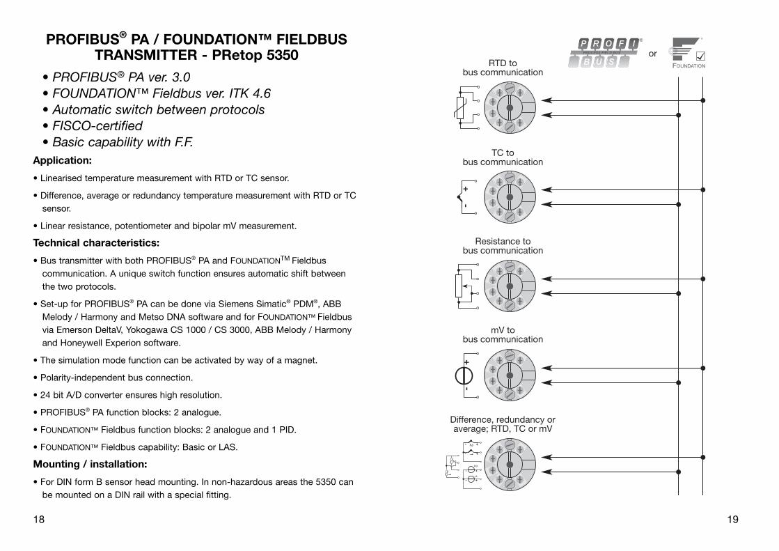
RTD tobus communication
Resistance tobus communication
mV tobus communication
TC tobus communication
Difference, redundancy oraverage; RTD, TC or mV
orPROFIBUS® PA / FOUNDATION™ FIELDBUS
TRANSMITTER - PRetop 5350
• PROFIBUS® PA ver. 3.0• FOUNDATION™ Fieldbus ver. ITK 4.6• Automatic switch between protocols• FISCO-certified• Basic capability with F.F.
Application:
• Linearised temperature measurement with RTD or TC sensor.
• Difference, average or redundancy temperature measurement with RTD or TC sensor.
• Linear resistance, potentiometer and bipolar mV measurement.
Technical characteristics:
• Bus transmitter with both PROFIBUS® PA and FOUNDATIONTM Fieldbus communi cation. A unique switch function ensures automatic shift between the two protocols.
• Set-up for PROFIBUS® PA can be done via Siemens Simatic® PDM®, ABB Melody / Harmony and Metso DNA software and for FOUN DATION™ Fieldbus via Emerson DeltaV, Yokogawa CS 1000 / CS 3000, ABB Melody / Harmony and Honeywell Experion software.
• The simulation mode function can be activated by way of a magnet.
• Polarity-independent bus connection.
• 24 bit A/D converter ensures high resolution.
• PROFIBUS® PA function blocks: 2 analogue.
• FOUNDATION™ Fieldbus function blocks: 2 analogue and 1 PID.
• FOUNDATION™ Fieldbus capability: Basic or LAS.
Mounting / installation:
• For DIN form B sensor head mounting. In non-hazardous areas the 5350 can be mounted on a DIN rail with a special fitting.
18

20 21
Vibration (DIN class B) ................................ IEC 60068-2-6 and IEC 60068-2-64 4 g / 2...100 HzHumidity ...................................................... < 95% RH (non cond.)Dimensions .................................................. Ø 44 x 20.2 mmTightness (enclosure / terminal) .................. IP68 / IP00Weight ......................................................... 55 gElectrical specifications, input:
RTD and linear resistance input:
Cable resistance per wire ............................ 50 Ω Sensor current ............................................. Nom. 0.2 mAEffect of sensor cable resistance (3- / 4-wire) < 0.002 Ω / ΩSensor error detection ................................ YesShort circuit detection ................................. < 15 Ω
21
Basic values
Input typeBasic
accuracyTemperaturecoefficient
Pt100 and Pt1000 ≤ ±0.1°C ≤ ±0.002°C / °C
Ni100 ≤ ±0.15°C ≤ ±0.002°C / °C
Cu10 ≤ ±1.3°C ≤ ±0.02°C / °C
Lin. R ≤ ±0.05 Ω ≤ ±0.002 Ω / °C
Volt ≤ ±10 µV ≤ ±0.2 µV / °C
TC type:E, J, K, L, N, T, U ≤ ±0.5°C ≤ ±0.010°C / °C
TC type:B, R, S, W3, W5 ≤ ±1°C ≤ ±0.025°C / °C
EMC immunity influence ................................ < ±0.1% of readingExtended EMC immunity:NAMUR NE 21, A criterion, burst .................. < ±1% of reading
RTDtype
Min.value
Max.value Norm
Pt25...Pt1000Ni25...Ni1000
Cu10...Cu1000Lin. resistancePotentiometer
-200°C-60°C-50°C0 Ω0 Ω
+850°C+250°C+200°C10 kΩ100 kΩ
IEC60751/JIS C 1604IEC60751
α = 0.00427--
*NB! Please remember to order PR sim pin type 8422if the simulation mode function is to be used.
Electrical specifications:
Specifications range:-40°C to +85°C
Common specifications:Supply voltage, DC Standard, 5350A ..................................... 9.0...32 V ATEX, FM, UL and CSA, 5350B .............. 9.0...30 V In FISCO installations ............................. 9.0...17.5 VConsumption ............................................... < 11 mAMax. current increase in the event of an error ............................... < 7 mAIsolation voltage, test .................................. 1.5 kVAC for 60 sIsolation voltage, operation ......................... 50 VRMS / 75 VDCWarm-up time .............................................. 30 sSignal / noise ratio ...................................... min. 60 dB Response time (programmable) .................. 1...60 sUpdating time .............................................. < 400 msExecution time, analogue input ................... < 50 msSignal dynamics, input ................................ 24 bitCalibration temperature .............................. 20...28°CAccuracy, the greater of general and basic values:
20
General values
Input typeAbsoluteaccuracy
Temperaturecoefficient
All ≤ ±0,05% of reading ≤ ±0.002% of reading / °C

22 2323
Ex data:Signal output / supply, terminal 1 to 2:Max. ambient temperature depends on the Po of the connected barrier.
Unit
5350B
Class I, Zone 0, EEx ia IIC, Entity / Fisco
IS, Class I, Division 1, Group A, B, C, DEntity / Fisco
Barrier wherePo < 0.84 W
Barrier wherePo < 1.3 W
Suitable forFISCO systems
Suitable forFISCO systems
U iI iP iL iC i
T1...T4T5T6
30 VDC120 mADC
0.84 W1 µH
2.0 nFTamb. < 85°CTamb. < 70°CTamb. < 60°C
30 VDC300 mADC
1.3 W1 µH
2.0 nFTamb. < 75°CTamb. < 65°CTamb. < 45°C
17.5 VDC250 mADC
2,0 W1 µH
2.0 nFTamb. < 85°CTamb. < 60°CTamb. < 45°C
15 VDC900 mA5.32 W1 µH
2.0 nFTamb. < 85°CTamb. < 60°CTamb. < 45°C
Unit
5350B 5350A
Class I, Zone 1, EEx ib IIC, Entity / Fisco Zone 2, EEx nA [L] IIC
IS, Class I, Division 2, Group A, B, C, DEntity / Fisco
Division 2,nonincendive
Barriere wherePo < 5.32 W
FISCO segment coupler
Nobarrier
U iI iP iL iC i
T1...T4T5T6
30 VDC250 mADC
5.32 W1 µH
2.0 nFTamb. < 85°CTamb. < 75°CTamb. < 60°C
17.5 VDCAllAll
1 µH2.0 nF
Tamb. < 85°CTamb. < 75°CTamb. < 60°C
32 VDC
Tamb. < 85°CTamb. < 75°CTamb. < 60°C
TC input:
Cold junction compensation (CJC) ............. < ±0.5 °CSensor error detection ................................ YesSensor error current: when detecting ....................................... Nom. 4 µA else .......................................................... 0 µAShort circuit detection ................................. < 3 mVVoltage input:Measurement range .................................... -800...+800 mVMin. measurement range (span) ................. 2.5 mVInput resistance ........................................... 10 MΩOutput:
PROFIBUS® PA connection:PROFIBUS® PA protocol .............................. Profile A&B, ver. 3.0PROFIBUS® PA protocol standard ............... EN 50170 vol. 2PROFIBUS® PA address (at delivery) ........... 126PROFIBUS® PA function blocks ................... 2 analogueFOUNDATIONTM Fieldbus connection:FOUNDATIONTM Fieldbus protocol ................. FF protocolFOUNDATIONTM Fieldbus protocol standard .. FF design specificationsFOUNDATIONTM Fieldbus capability ............... Basic or LASFOUNDATIONTM Fieldbus version ................... ITK 4.6FOUNDATIONTM Fieldbus function blocks ...... 2 analogue and 1 PID
22
TypeMin.value
Max.value Norm
BEJKLNRSTU
W3W5
Ext. CJC
+400°C-100°C-100°C-180°C-200°C-180°C-50°C-50°C
-200°C-200°C
0°C0°C
-40°C
+1820°C+1000°C+1200°C+1372°C+900°C
+1300°C+1760°C+1760°C+400°C+600°C
+2300°C+2300°C+135°C
IEC584IEC584IEC584IEC584
DIN 43710IEC584IEC584IEC584IEC584
DIN 43710ASTM E988-90ASTM E988-90
IEC6075

24 252524
Ex / I.S. data:Sensor input, terminal 3, 4, 5 and 6:Uo .......................................................... : 5.71 VDCI o ............................................................ : 8.4 mAPo ........................................................... : 12 mWLo ........................................................... : 200 mHCo ........................................................... : 40 µF
EEx / I.S. approval:Instructions for safe installation: Installation Drawing No. .......................... 5350QE01
5350A:
KEMA 03ATEX1011 X .................................. II 3 G EEx nA [L] II C T4...T6FM, UL and CSA ......................................... IS, Class I, Div. 2, Group A, B, C, D IS, Class I, Zone 2, Group IIC
5350B:
KEMA 02ATEX1318 ..................................... II 1 GD or II 2 (1) GD, T65°C...T105°C EEx ia IIC or EEx ib [ia] IIC T4...T6Applicable in zone ....................................... 0, 1, 2, 20, 21 or 22FM, UL and CSA ......................................... IS, Class I, Div. 1, Group A, B, C, D IS, Class I, Zone 0/1, Group IIC IS, Class I, Div. 2, Group A, B, C, D
Observed authority requirements: Standard:EMC 2004/108/EC Emission and immunity ....................... EN 61326ATEX 94/9/EC .............................................. EN 50014, EN 50020, EN 50021 EN 50281-1-1 and EN 50284 IEC 60079-27 (FISCO)FM, ASCN ................................................... 3600, 3610, 3611UL ................................................................ UL 508, UL 1604, UL 913, UL 60079-0, UL 60079-1CSA, CAN / CSA ......................................... C22.2 No. 142, No. 157, No. 213,CAN / CSA .................................................. E79-0, -11, -15 ANSI / UL .................................................... UL 60079-0, -11, -15

26 27
Block diagram:
27
1 2
1 2PA
Connections:
Output:
Bus connection
Bus connection
Segmentcoupler
Segmentcoupler
Bustermination
Bustermination
26
Wires must be mounted between the metal plates.
Mechanical specifications: Mounting of sensor wires

28 29
TRANSMETTEUR PROFIBUS® PA /FIELDBUS FOUNDATION™
PRetrans 5350
Sommaire
Consigne de sécurité ......................................................... 30Installation ATEX 5350QA01 .............................................. 30Déclaration de conformité .................................................. 31Application ......................................................................... 32Caractéristiques techniques .............................................. 32Montage / installation ......................................................... 32Applications ........................................................................ 33Référence ........................................................................... 34Spécifications électriques .................................................. 34Connexions, entrée ............................................................ 39Connexions, sortie ............................................................. 40Montage des fils du capteur .............................................. 40Schéma de principe ........................................................... 41Installation bus ................................................................... 42Appendix:FM, UL, CSA and FISCOInstallation Drawing No. 5350QE01 ................................... 57
29
Bus installation:
28

30 31
DECLARATION DE CONFORMITEEn tant que fabricant
PR electronics A/S
Lerbakken 10
DK-8410 Rønde
déclare que le produit suivant :
Type: 5350
Nom: Transmetteur PROFIBUS® PA / Fieldbus FOUNDATIONTM
correspond aux directives et normes suivantes :
La directive CEM (EMC) 2004/108/CE et les modifications subséquentes
EN 61326
Cette déclaration est délivrée en correspondance à l’article 10, alinéa 1 de la directive CEM. Pour une spécification du niveau de rendement acceptable CEM (EMC) se référer aux spécifications électriques du module.
La directive ATEX 94/9/CE et les modifications subséquentes
EN 50014, EN 50020, EN 50021
EN 50281-1-1 et EN 50284
IEC 60 079-27 (FISCO)
Certificat ATEX : KEMA 03ATEX1011 X (5350A)
Certificat ATEX : KEMA 02ATEX1318 (5350B)
Organisme notifié pour CENELEC / ATEX : UL International Demko A/S 0539
Rønde, 17 novembre 2005 Peter Rasmussen Signature du fabricant
3130
Consigne de sécuritéInstallation S.I. :
Pour l’installation de 5350 dans les zones dangereuses, conformez-vous aux consignes de sécurité suivantes : l’installation ne doit être réalisée que par du personnel qualifié connaissant la législation nationale et internationale ainsi que les directives et standards régissant ce domaine.
Pour les données de sécurité intrinsèque, voir les certificats ATEX et l’Instal-lation Drawing No. 5350QE01.
Installation ATEX 5350QA01 :
L’isolation galvanique entre le circuit du capteur et le circuit d’entrée Fieldbus n’est pas infaillible. Cependant, l’isolation galvanique entre les circuits est capable de résister à une tension de test de 500Vca pendant 1 minute.
L’année de production ressort des deux premiers chiffres du numéro de série.
Les transmetteurs ne contiennent aucune pièce amovible.
Le 5350B doit être monté dans un boîtier assurant un degré d’étanchéité d’au moins IP20. Si le transmetteur est installé dans une atmosphère potentielle-ment explosive exigeant de l’équipement en catégorie 1G et si le boîtier con-tenant le transmetteur est fait d’aluminium, les exigences de l’EN 50284, article 4.3.1, doivent être prises en considération.
Le 5350B doit seulement être installé dans les atmosphères potentiellement explosives dû à la présence de poussières combustibles quand il est montédans un boîtier métallique DIN B conformément à DIN 43729 assurant un degré d’étanchéité d’au moins IP 6X conformément à l’EN 60529. Ce boîtier doit convenir à l’application et il doit être correctement installé.
Seulement des raccords de câble et des bouchons convenant à l’application et correctement installés doivent être utilisés.
Pour une température ambiante ≥ 60°C, il faut utiliser des câbles résistant aux températures élevées avec une capacité nominale d’au moins 20K au dessus de la température ambiante.
La température superficielle du boîtier égale la température ambiante plus 20K, pour une couche de poussière d’un épaisseur jusqu’à 5 mm.
Le 5350A doit être installé dans un boîtier de protection assurant un degré d’étanchéité d’au moins IP54 conformément à l’EN 60529.
Il faut prendre des mesures pour éviter que la tension d’alimentation nominelle soit dépassée par plus de 40%.

32 3333
+-
+-
+- 1+- 2
+-
+-
2
12
1
RTD encommunication de bus
Résistance encommunication de bus
mV encommunication de bus
TC encommunication de bus
Différence, redondance oumoyenne; RTD, TC ou mV
ou
TRANSMETTEUR PROFIBUS® PA / FIELDBUS FOUNDATION™ - PRetop 5350
• PROFIBUS® PA ver. 3.0• Fieldbus FOUNDATION™ ver. ITK 4.6• Commutation automatique entre protocoles• Certifié aux normes FISCO• Basic en Fieldbus Foundation™
Application :
• Mesure linéarisée de la température avec sonde résistive ou thermocouple.
• Mesure de la température différentielle, moyenne ou redondance avec sonde résistive ou thermocouple.
• Résistance linéaire, potentiomètre et mesure de tension bipolaire (mV).
Caractéristiques techniques :
• Transmetteur de bus avec communication PROFIBUS® PA et Fieldbus FOUN-
DATIONTM. Une fonction de commutation unique assure le passage d’un pro-tocole à l’autre de manière automatique.
• Configuration PROFIBUS® PA avec les logiciels Siemens Simatic® PDM®, ABB Melody / Harmony et Metso DNA et Fieldbus FOUNDATION™ avec les logiciels Emerson DeltaV, Yokogawa CS 1000 / CS 3000, ABB Melody / Harmony et Honeywell Experion.
• Le mode de simulation peut être activé à l’aide d’un aimant.
• La connexion du bus est indépendante de la polarité.
• Le convertisseur A/D de 24 bit assure une très haute résolution du signal.
• Blocs de fonctions PROFIBUS® PA : 2 blocs analogiques.
• Blocs de fonctions Fieldbus FOUNDATION™ : 2 blocs analogiques et 1 bloc PID.
• Fonctionnalités en Fieldbus FOUNDATION™ : Basic. ou LAS.
Montage / installation :
• Pour tête de sonde DIN B. En zone non-dangereuse le 5350 peut être monté sur rail DIN avec un support spécifique.
32

34 35
Vibration (DIN class B) ................................ IEC 60068-2-6 et IEC 60068-2-64 4 g / 2...100 HzHumidité ...................................................... < 95% RH (sans cond.)Dimensions .................................................. Ø 44 x 20,2 mmEtanchéité (boîtier / bornier) ........................ IP68 / IP00Poids ........................................................... 55 gSpécifications électriques, entrée :
Entrée résistance linéaire et RTD :
Résistance de ligne par fil ........................... 50 Ω Courant de sonde ....................................... Nom. 0,2 mAEffet de la résistance de ligne (3- / 4-fils) ... < 0,002 Ω / ΩDétection de rupture sonde ........................ OuiDétection de court-circuit ........................... < 15 Ω
35
Valeurs de base
Typed’entrée
Précisionde base
Coefficientde température
Pt100 et Pt1000 ≤ ±0,1°C ≤ ±0,002°C / °C
Ni100 ≤ ±0,15°C ≤ ±0,002°C / °C
Cu10 ≤ ±1,3°C ≤ ±0,02°C / °C
R. lin. ≤ ±0,05 Ω ≤ ±0,002 Ω / °C
Volt ≤ ±10 µV ≤ ±0,2 µV / °C
Type TC :E, J, K, L, N, T, U ≤ ±0,5°C ≤ ±0,010°C / °C
Type TC :B, R, S, W3, W5 ≤ ±1°C ≤ ±0,025°C / °C
Immunité CEM ................................................ < ±0,1% d. la valeurImmunité CEM améliorée :NAMUR NE 21, critère A, burst ..................... < ±1% de la valeur
TypeRTD
Valeurmin.
Valeurmax. Norme
Pt25...Pt1000Ni25...Ni1000
Cu10...Cu1000Résistance lin.Potentiomètre
-200°C-60°C-50°C0 Ω0 Ω
+850°C+250°C+200°C10 kΩ100 kΩ
IEC60751/JIS C 1604IEC60751
α = 0,00427--
*N.B. ! Si le mode de simulation doit être activé,rappellez-vous de commander le PR sim pin type 8422.
Spécifications électriques :
Plage des spécifications :-40°C à +85°C Spécifications communes :Tension d’alimentation, cc Standard, 5350A ..................................... 9,0...32 V ATEX, FM, UL et CSA, 5350B ................. 9,0...30 V Dans les installations FISCO .................. 9,0...17,5 VConsommation ............................................ < 11 mAAugmentation max. de la consommation lors d’une erreur ...................................... < 7 mATension d’isolation, test ............................... 1,5 kVca pendant 60 sTension d’isolation, opération ..................... 50 VRMS / 75 VccTemps de chauffe ........................................ 30 sRapport signal / bruit .................................. min. 60 dB Temps de réponse (programmable) ............ 1...60 sTemps de scrutation .................................... < 400 msTemps d’exécution, entrée analogique ....... < 50 msDynamique du signal d’entrée .................... 24 bitTempérature d’étalonnage .......................... 20...28°CPrécision, la plus grande des valeurs générales et de base :
34
Valeurs générales
Typed’entrée
Précisionabsolue
Coefficientde température
Tous ≤ ±0,05% de la valeur ≤ ±0,002% de la valeur / °C

36 3737
Caractéristiques S.I. :Sortie de signal / alimentation, borne 1 à 2:La température ambiante max. dépend de la valeur Po de la barrière connectée.
Unité
5350B
Class I, Zone 0, EEx ia IIC, Entity / Fisco
IS, Class I, Division 1, Group A, B, C, DEntity / Fisco
Barrière oùPo < 0,84 W
Barrière oùPo < 1,3 W
Peut être utilisé ensystèmes FISCO
Peut être utilisé ensystèmes FISCO
U iI iP iL iC i
T1...T4T5T6
30 Vcc120 mAcc
0,84 W1 µH
2,0 nFTamb. < 85°CTamb. < 70°CTamb. < 60°C
30 Vcc300 mAcc
1,3 W1 µH
2,0 nFTamb. < 75°CTamb. < 65°CTamb. < 45°C
17,5 Vcc250 mAcc
2,0 W1 µH
2,0 nFTamb. < 85°CTamb. < 60°CTamb. < 45°C
15 Vcc900 mA5,32 W1 µH
2,0 nFTamb. < 85°CTamb. < 60°CTamb. < 45°C
Unité
5350B 5350A
Class I, Zone 1, EEx ib IIC, Entity / Fisco Zone 2, EEx nA [L] IIC
IS, Class I, Division 2, Group A, B, C, DEntity / Fisco
Division 2,non incendiaire
Barrière oùPo < 5,32 W
Coupleur de segment FISCO
Pas debarrière
U iI iP iL iC i
T1...T4T5T6
30 Vcc250 mAcc
5,32 W1 µH
2,0 nFTamb. < 85°CTamb. < 75°CTamb. < 60°C
17,5 VccToutesToutes1 µH
2,0 nFTamb. < 85°CTamb. < 75°CTamb. < 60°C
32 Vcc
Tamb. < 85°CTamb. < 75°CTamb. < 60°C
Entrée TC :
Compensation de soudure froide (CSF) ..... < ±0,5 °CDétection de rupture sonde ........................ OuiCourant de sonde: pendant la détection ............................... Nom. 4 µA si non ...................................................... 0 µADétection de court-circuit ........................... < 3 mVEntrée tension :Gamme de mesure ...................................... -800...+800 mVPlage de mesure min. (échelle) ................... 2,5 mVRésistance d’entrée .................................... 10 MΩSortie :
Connexion PROFIBUS® PA :Protocole PROFIBUS® PA ............................. Profile A&B, ver. 3.0Standard protocole PROFIBUS® PA ............ EN 50170 vol. 2Adresse PROFIBUS® PA (à la livraison) ....... 126Blocs de fonctions PROFIBUS® PA ............. 2 bloc analogiquesConnexion Fieldbus FOUNDATIONTM :Protocole Fieldbus FOUNDATIONTM ............... Protocole FFStd protocole Fieldbus FOUNDATIONTM ........ Spécifications au design FFFonctionnalités Fieldbus FOUNDATIONTM ...... Basic ou LASVersion Fieldbus FOUNDATIONTM .................. ITK 4.6Blocs de fonctions Fieldbus FOUNDATIONTM .. 2 blocs analogiques et 1 bloc PID
36
TypeValeurmin.
Valeurmax. Norme
BEJKLNRSTU
W3W5
CSF ext.
+400°C-100°C-100°C-180°C-200°C-180°C-50°C-50°C
-200°C-200°C
0°C0°C
-40°C
+1820°C+1000°C+1200°C+1372°C+900°C
+1300°C+1760°C+1760°C+400°C+600°C
+2300°C+2300°C+135°C
IEC584IEC584IEC584IEC584
DIN 43710IEC584IEC584IEC584IEC584
DIN 43710ASTM E988-90ASTM E988-90
IEC60751

38 393938
Caractéristiques S.I. :Entrée sonde, bornes 3, 4, 5 et 6:Uo .......................................................... : 5,71 VccI o ............................................................ : 8,4 mAPo ........................................................... : 12 mWLo ........................................................... : 200 mHCo ........................................................... : 40 µF
Approbation EEx / I.S. :Instructions d’installation sûre : Installation Drawing No. .......................... 5350QE01
5350A:
KEMA 03ATEX1011 X .................................. II 3 G EEx nA [L] II C T4...T6FM, UL et CSA ............................................ IS, Class I, Div. 2, Group A, B, C, D IS, Class I, Zone 2, Group IIC
5350B :
KEMA 02ATEX1318 ..................................... II 1 GD ou II 2 (1) GD T65°C...T105°C EEx ia IIC ou EEx ib [ia] IIC T4...T6Applicable en zone ...................................... 0, 1, 2, 20, 21 ou 22FM, UL et CSA ............................................ IS, Class I, Div. 1, Group A, B, C, D IS, Class I, Zone 0/1, Group IIC IS, Class I, Div. 2, Group A, B, C, D
Agréments et homologations : Standard :EMC 2004/108/CE Emission et immunité ....................... EN 61326ATEX 94/9/CE .............................................. EN 50014, EN 50020, EN 50021 EN 50281-1-1 et EN 50284 IEC 60079-27 (FISCO)FM, ASCN ................................................... 3600, 3610, 3611UL ................................................................ UL 508, UL 1604, UL 913, UL 60079-0, UL 60079-1CSA, CAN / CSA ......................................... C22.2 No. 142, No. 157, No. 213,CAN / CSA .................................................. E79-0, -11, -15 ANSI / UL .................................................... UL 60079-0, -11, -15

40 41
Schema de principe :
41
1 2
1 2PA
Connexions :
Sortie :Connexion bus
Connexion bus
Coupleur desegment
Coupleur desegment
Terminaisonbus
Terminaisonbus
40
Dimensions mécaniques : Montage des fils du capteur
Les fils doivent être montés entre les plaques métalliques.

42 43
PROFIBUS® PA / FOUNDATION™ FIELDBUS MESSUMFORMER
PRetrans 5350
Inhaltsverzeichnis
Sicherheitsanweisung ........................................................ 44ATEX Installationsanweisung 5350QA01 ........................... 44Konformitätserklärung ........................................................ 45Verwendung ........................................................................ 46Technische Merkmale ......................................................... 46Montage / Installation ......................................................... 46Anwendungen .................................................................... 47Bestellangaben ................................................................... 48Elektrische Daten ............................................................... 48Anschlüsse, Eingang .......................................................... 53Anschlüsse, Ausgang ......................................................... 54Montage von Fühlerleitungen ............................................. 54Blockdiagramm .................................................................. 55Businstallation .................................................................... 56Appendix:FM, UL, CSA and FISCOInstallation Drawing No. 5350QE01 ................................... 57
43
Installation bus :
42

44 45
KONFORMITÄTSERKLÄRUNGAls Hersteller bescheinigt
PR electronics A/S
Lerbakken 10
DK-8410 Rønde
hiermit für das folgende Produkt:
Typ: 5350
Name: PROFIBUS® PA / FOUNDATION™ Fieldbus
Messumformer
die Konformität mit folgenden Richtlinien und Normen:
EMV Richtlinien 2004/108/EG und nachfolgende Änderungen
EN 61326
Diese Erklärung ist in Übereinstimmung mit Artikel 10, Unterklausel 1 der EMV Richtlinie ausgestellt. Zur Spezifikation des zulässigen Erfüllungsgrades, siehe die Elektrische Daten des Moduls.
Die ATEX Richtlinien 94/9/EC und nachfolgende Änderungen
EN 50014, EN 50020, EN 50021
EN 50281-1-1 und EN 50284
IEC 60 079-27 (FISCO)
ATEX-Zertifikat: KEMA 03ATEX1011 X (5350A)
ATEX-Zertifikat: KEMA 02ATEX1318 (5350B)
Zulassungsstelle für CENELEC / ATEX: UL International Demko 0539
Rønde, 17. Nov. 2005 Peter Rasmussen Unterschrift des Herstellers
4544
SicherheitsanweisungEx-Installation:Für sichere Installation von 5350 in explosionsgefährdeter Umgebung muss fol-
gendes beobachtet werden. Die Installation muss nur von qualifizierten Per-sonen, die mit den nationalen und internationalen Gesetze, Direktiven und Standards des Gebiets bekannt sind, vorgenommen werden.
Für Ex-Daten siehe ATEX-Zertifikate und Installation Drawing No. 5350QE01.
Installationsanweisung 5350QA01:Die galvnische Trennung zwischen dem Sensorkreis und dem Feldbus Eingangs-
kreis ist nicht unfehlbar. Allerdings ist die galvanische Trennung zwischen den Kreisen so ausgelegt, dass diese eine Testspannung von 500Vac für eine Minute aushält.
Das Produktionsjahr der Messumformer ist an den ersten zwei Ziffern der Serien-nummer abzulesen.
Es befinden sich keine zu wartenden Bauteile in dem Messumformer.
Der Messumformer 5350B muss in einem Gehäuse montiert werden, um die Mindestanforderung des Berührungsschutzes mit dem Schutzgrad IP 20 zu erreichen. Wird der Messumformer in einer potentiellen explosiven Atmo-sphäre mit der Anforderung der Kategorie 1G eingesetzt, und das eingesetzte Gehäuse ist aus Aluminium, müssen die Anforderungen der EN 50284, Kapi-tel 4.3.1 beachtet werden.
Der 5350B darf nur in einer potentiellen explosiven Atmosphäre, basierend auf entflammbaren Staub, eingesetzt werden, wenn er in einem Metallkopf Form B gemäß DIN 43729 montiert ist, welcher einen Schutzgrad von minde-stens IP 6X gemäß EN 60529 besitzt und für den dementsprechenden Einsatz zugelassen ist..
Es dürfen nur Kabeleinführungen und Abdeckungen eingesetzt werden, welche für die jeweilige Anwendung zugelassen sind.
Bei einer Umgebungstemperatur ≥ 60°C müssen hitzebeständige Leitungen eingesetzt werden, welche für eine mindestens 20K höhere Umgebungstem-peratur zugelassen sind.
Die Umgebungstemperatur der Gehäuse entspricht der Umgebungstemperatur plus 20K für eine Staubschicht mit einer Dicke von bis zu 5 mm.
Der Messumformer 5350A muss in einem Gehäuse entsprechend dem Berührungsschutz der Schutzklasse IP 54 gemäß EN 60529 eingebaut wer-den.
Es müssen Maßnahmen getroffen werden, dass die Versorgungsspannung nicht höher als 40% über die Bemessungsspannung steigt.

46 4747
+-
+-
+- 1+- 2
+-
+-
2
12
1
WTH inBus-Kommunikation
Widerstand inBus-Kommunikation
mV inBus-Kommunikation
TE inBus-Kommunikation
Differenz, Redundanz oderMittel; WTH, TE oder mV
oder
PROFIBUS® PA / FOUNDATION™ FIELDBUS MESSUMFORMER - PRetop 5350
• PROFIBUS® PA Version 3.0• FOUNDATION™ Fieldbus Version ITK 4.6• Automatische Protokoll-Umschaltung• FISCO-zertifiziert• F.F. mit Basic-Funktionalität
Anwendungen:
• Linearisierte Temperaturmessungen mit Widerstandsthermometer oder Ther-moelement.
• Differenz-, Mittelwert- oder redundante Temperaturmessungen mit Wider-standsthermometer oder Thermoelement.
• Lineare Widerstands-, Kompensator- und bipolare mV-Messungen.
Technische Merkmale:
• Bus-Messumformer mit PROFIBUS® PA und FOUNDATION™ Fieldbus-Kommunikation. Die einzigartige Umschaltfunktion ermöglicht eine automati-sche Umschaltung zwischen den beiden Protokollen.
• Konfiguration über PROFIBUS® PA mit Siemens Simatic® PDM®, ABB Melody /Harmony und Metso DNA Software und über FOUN DATION™ Fieldbus mit Emerson DeltaV, Yokogawa CS 1000 / CS 3000, ABB Melody / Harmony und Honeywell Experion Software.
• Der Simulationsmodus kann mittels eines Magneten aktiviert werden.
• Polaritätsunabhängige Busanschluss.
• Der 24 Bit A/D-Wandler garantiert eine hohe Auflösung.
• PROFIBUS® PA Funktionsblöcke: 2 Analoge.
• FOUNDATION™ Fieldbus Funktionsblöcke: 2 Analoge und 1 PID.
• FOUNDATION™ Fieldbus Funktionalität: Basic oder LAS.
Montage / Installation:
• Für DIN Form B Sensorkopf Montage. Im sicheren Bereich kann der 5350 auf einer DIN- Schiene mittels einer spezieller Armatur montiert werden.
46
48 49
Schwingungen (DIN class B) ....................... IEC 60068-2-6 und IEC 60068-2-64 4 g / 2...100 HzFeuchtigkeit ................................................. < 95% RF (nicht kond.)Abmessungen ............................................. Ø 44 x 20,2 mmSchutzart (Gehäuse / Klemmen) ................. IP68 / IP00Gewicht ....................................................... 55 gElektrische Daten, Eingang:
WTH- und linearer Widerstandseingang:
Leitungswiderstand pro Leiter .................... 50 ΩFühlerstrom ................................................. Nom. 0,2 mAWirkung des Fühlerkabelwiderst. (3-/4-Leiter) < 0,002 Ω / ΩFühlerfehlererkennung ................................. JaKurzschlusserkennung ................................ < 15 Ω
49
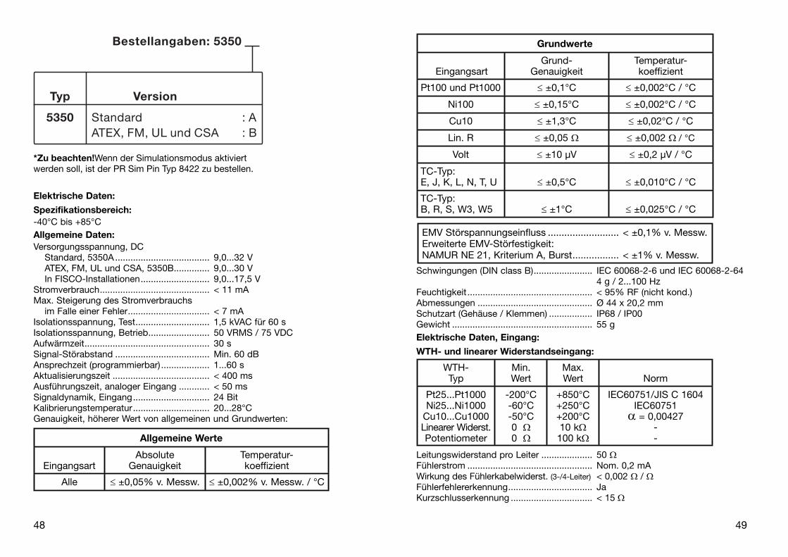
Grundwerte
EingangsartGrund-
GenauigkeitTemperatur-koeffizient
Pt100 und Pt1000 ≤ ±0,1°C ≤ ±0,002°C / °C
Ni100 ≤ ±0,15°C ≤ ±0,002°C / °C
Cu10 ≤ ±1,3°C ≤ ±0,02°C / °C
Lin. R ≤ ±0,05 Ω ≤ ±0,002 Ω / °C
Volt ≤ ±10 µV ≤ ±0,2 µV / °C
TC-Typ:E, J, K, L, N, T, U ≤ ±0,5°C ≤ ±0,010°C / °C
TC-Typ:B, R, S, W3, W5 ≤ ±1°C ≤ ±0,025°C / °C
EMV Störspannungseinfluss .......................... < ±0,1% v. Messw.Erweiterte EMV-Störfestigkeit:NAMUR NE 21, Kriterium A, Burst ................. < ±1% v. Messw.
WTH-Typ
Min.Wert
Max.Wert Norm
Pt25...Pt1000Ni25...Ni1000
Cu10...Cu1000Linearer Widerst.Potentiometer
-200°C-60°C-50°C0 Ω0 Ω
+850°C+250°C+200°C10 kΩ100 kΩ
IEC60751/JIS C 1604IEC60751
α = 0,00427--
*Zu beachten! Wenn der Simulationsmodus aktiviertwerden soll, ist der PR Sim Pin Typ 8422 zu bestellen.
Elektrische Daten:
Spezifikationsbereich:-40°C bis +85°CAllgemeine Daten:Versorgungsspannung, DC Standard, 5350A ..................................... 9,0...32 V ATEX, FM, UL und CSA, 5350B .............. 9,0...30 V In FISCO-Installationen ........................... 9,0...17,5 VStromverbrauch ........................................... < 11 mAMax. Steigerung des Stromverbrauchs im Falle einer Fehler ................................ < 7 mAIsolationsspannung, Test ............................. 1,5 kVAC für 60 sIsolationsspannung, Betrieb ........................ 50 VRMS / 75 VDCAufwärmzeit ................................................. 30 sSignal-Störabstand ..................................... Min. 60 dB Ansprechzeit (programmierbar) ................... 1...60 sAktualisierungszeit ...................................... < 400 msAusführungszeit, analoger Eingang ............ < 50 msSignaldynamik, Eingang .............................. 24 BitKalibrierungstemperatur .............................. 20...28°CGenauigkeit, höherer Wert von allgemeinen und Grundwerten:
48
Allgemeine Werte
EingangsartAbsolute
GenauigkeitTemperatur-koeffizient
Alle ≤ ±0,05% v. Messw. ≤ ±0,002% v. Messw. / °C

50 5151
Ex-Daten:Signalausgang / Versorgung, Klemme 1 bis 2:Max. Umgebungstemperatur in Abhängigkeit von Po des angeschlossenen Ex-Trenners.
Einheit
5350B
Class I, Zone 0, EEx ia IIC, Entity / Fisco
IS, Class I, Division 1, Group A, B, C, DEntity / Fisco
Barriere mitPo < 0,84 W
Barriere mitPo < 1,3 W
Anwendung inFISCO-Systeme
Anwendung inFISCO-Systeme
U iI iP iL iC i
T1...T4T5T6
30 VDC120 mADC
0,84 W1 µH
2,0 nFTUmg. < 85°CTUmg. < 70°CTUmg. < 60°C
30 VDC300 mADC
1,3 W1 µH
2,0 nFTUmg. < 75°CTUmg. < 65°CTUmg. < 45°C
17,5 VDC250 mADC
2,0 W1 µH
2,0 nFTUmg. < 85°CTUmg. < 60°CTUmg. < 45°C
15 VDC900 mA5,32 W1 µH
2,0 nFTUmg. < 85°CTUmg. < 60°CTUmg. < 45°C
Einheit
5350B 5350A
Class I, Zone 1, EEx ib IIC, Entity / Fisco Zone 2, EEx nA [L] IIC
IS, Class I, Division 2, Group A, B, C, DEntity / Fisco
Division 2,nicht-zündfähig
Barriere mitPo < 5,32 W
FISCO Seg-mentkoppler
KeineBarriere
U iI iP iL iC i
T1...T4T5T6
30 VDC250 mADC
5,32 W1 µH
2,0 nFTUmg. < 85°CTUmg. < 75°CTUmg. < 60°C
17,5 VDCAlleAlle1 µH
2,0 nFTUmg. < 85°CTUmg. < 75°CTUmg. < 60°C
32 VDC
TUmg. < 85°CTUmg. < 75°CTUmg. < 60°C
TE-Eingang:
Vergleichstellungskompensation (CJC) ....... < ±0,5 °CFühlerfehlererkennung ................................. JaFühlerfehlerstrom: Bei Erkennung ......................................... Nom. 4 µA Sonst ....................................................... 0 µAKurzschlusserkennung ................................ < 3 mVSpannungseingang:Messbereich ................................................ -800...+800 mVMin. Messbereich (Spanne) ......................... 2,5 mVEingangswiderstand .................................... 10 MΩAusgang:
PROFIBUS® PA-Verbindung:PROFIBUS® PA Protokoll ............................. Profil A&B, Ver. 3.0PROFIBUS® PA Protokollnorm ..................... EN 50170 Vol. 2PROFIBUS® PA Adresse (bei Lieferung) ....... 126PROFIBUS® PA Funktionsblöcke ................. 2 AnalogeFOUNDATIONTM Fieldbus-Verbindung:FOUNDATIONTM Fieldbus Protokoll ................ FF ProtokollFOUNDATIONTM Fieldbus Protokollnorm ........ FF AuslegungsbestimmungenFOUNDATIONTM Fieldbus Funktionalität ......... Basic oder LASFOUNDATIONTM Fieldbus Version ................... ITK 4.6FOUNDATIONTM Fieldbus Funktionsblöcke .... 2 Analoge and 1 PID
50
TypMin.Wert
Max.Wert Norm
BEJKLNRSTU
W3W5
Ext. CJC
+400°C-100°C-100°C-180°C-200°C-180°C-50°C-50°C
-200°C-200°C
0°C0°C
-40°C
+1820°C+1000°C+1200°C+1372°C+900°C
+1300°C+1760°C+1760°C+400°C+600°C
+2300°C+2300°C+135°C
IEC584IEC584IEC584IEC584
DIN 43710IEC584IEC584IEC584IEC584
DIN 43710ASTM E988-90ASTM E988-90
IEC60751

52 535352
Ex-/ I.S.-Daten:Fühlereingang, Klemme 3, 4, 5 und 6:Uo .......................................................... : 5,71 VDCI o ............................................................ : 8,4 mAPo ........................................................... : 12 mWLo ........................................................... : 200 mHCo ........................................................... : 40 µF
EEx- / I.S.-Zulassung:Anweisungen für sichere Installation: Installation Drawing No. .......................... 5350QE01
5350A:
KEMA 03ATEX1011 X .................................. II 3 G EEx nA [L] II C T1...T6FM, UL und CSA ......................................... IS, Class I, Div. 2, Group A, B, C, D IS, Class I, Zone 2, Group IIC
5350B:
KEMA 02ATEX1318 ..................................... II 1 GD oder II 2 (1) GD T65°C...T105°C EEx ia IIC oder EEx ib [ia] IIC T1...T6Anwendung in Zone .................................... 0, 1, 2, 20, 21 oder 22FM, UL und CSA ......................................... IS, Class I, Div. 1, Group A, B, C, D IS, Class I, Zone 0/1, Group IIC IS, Class I, Div. 2, Group A, B, C, D
Eingehaltene Richtlinien: Norm:EMC 2004/108/EG Abstrahlung und Störfestigkeit ................. EN 61326ATEX 94/9/EG .............................................. EN 50014, EN 50020, EN 50021 EN 50281-1-1 und EN 50284 IEC 60079-27 (FISCO)FM, ASCN ................................................... 3600, 3610, 3611UL ................................................................ UL 508, UL 1604, UL 913, UL 60079-0, UL 60079-1CSA, CAN / CSA ......................................... C22.2 No. 142, No. 157, No. 213,CAN / CSA .................................................. E79-0, -11, -15 ANSI / UL .................................................... UL 60079-0, -11, -15

54 55
Blockdiagramm:
55
1 2
1 2PA
Anschlüsse:
Ausgang:
Bus-Verbindung
Bus-Verbindung
Segment-koppler
Segment-koppler
Bus-Abschluss
Bus-Abschluss
54
Abmessungen: Montage von Fühlerleitungen:
Die Leitungen müssen zwischen den Metallplatten montiert werden.

56 57
APPENDIX
FM, UL, CSA and FISCOInstallation Drawing No.
5350QE01
57
Businstallation:
56

58 59
5350QE01.doc 2005-03-16 Rev. AC 1/7
Installation Drawing 5350QE01.
See Installation notes.
Terminal 1,2
Class I, Zone 0, Ex ia IIC, Entity / FISCO
IS, Class I, Division 1, Group A, B, C, D Entity / FISCO
Barriertype:
Linearbarrier
Trapezoidbarrier
Suitable for FISCO
systems
Suitable for FISCO
systemsT1..T4: Ta +85C Ta +75C Ta +85C Ta +85C
T5: Ta +70C Ta +65C Ta +60C Ta +60C
T6: Ta +60C Ta +45C Ta +45C Ta +45C
Vmax or Ui 30 V 30 V 17.5 V 15 V
Imax or Ii 120 mA 300 mA 250 mA 900 mA
Pi 0.84 W 1.3 W 2.0 W 5.32W
Ci 2.0 nF 2.0 nF 2.0 nF 2.0 nF
Li 1 H 1 H 1 H 1 H
Unclassified LocationHazardous (Classified) Location
Class I, Division1, Groups, A,B,C,DORClass I, Zone 0, IIC
Associated ApparatusBarrier or
FISCO Supplywith
entity Parameters:
ApprovedTermi-nation
SENSOR
5350B
1 2
3
45
6
SENSOR
5350B
1 2
3
45
6
SENSOR
5350B
1 2
3
45
6
Terminal 3, 4, 5, 6Vt or Uo : 5.71 VIt or Io : 8.4 mAPt or Po : 12 mW
or Co : 40 uFLa or Lo : 200 mH
UM < 250VVoc or Uo < Vmax or UiIsc or Io < Imax or IiPo < PiCa or Co > Ci + CcableLa or Lo > Li + Lcable
This device must not beconnected to any
associated apparatuswhich uses or generates
more than 250 VRMS
Ca
5350QE01.doc 2005-03-16 Rev. AC 2/7
Unclassified LocationHazardous (Classified) Location
Class I, Division2, Groups, A,B,C,DORClass I, Zone 1, IIC
Associated ApparatusBarrier with
entity Parameters:
ApprovedTermi-nation
SENSOR
5350B
1 2
3
45
6
SENSOR
5350B
1 2
3
45
6
SENSOR
5350B
1 2
3
45
6
Terminal 3, 4, 5, 6Vt or Uo : 5.71 VIt or Io : 8.4 mAPt or Po : 12 mWCa or Co : 40 uFLa or Lo : 200 mH
UM < 250VVoc or Uo < Vmax or UiIsc or Io < Imax or IiPo < PiCa or Co > Ci + CcableLa or Lo > Li + Lcable
orFISCO Supply
This device must not beconnected to any
associated apparatuswhich uses or generates
more than 250 VRMS
Nonincendive Field Wiring parametersTerminal 1, 2
NI, Class I, Division 2, Group A, B, C, DNIFW/ FNICO
T1..T4: Ta +85C Ta +85C
T5: Ta +75C Ta +75C
T6: Ta +60C Ta +60C
Vmax / Ui 30 V 17.5 V
Pi 5.32 W any
Ci 2.0 nF 2.0 nF
Li 1 H 1 H
For a current-controlled circuit theparameter Imax is not required and need not be aligned with the parameterIsc or It of the barrier or associated nonincendive field wiring apparatus.
EntityParametersTerminal 1, 2
Class I, Zone 1, Ex ib IICEntity / FISCO
Barrier type: Rectangularbarrier
FISCOSegmentcoupler
T1..T4: Ta +85C Ta +85C
T5: Ta +75C Ta +75C
T6: Ta +60C Ta +60C
Vmax / Ui 30 V 17.5 V
Imax or Ii 250 mA any
Pi 5.32 W any
Ci 2.0 nF 2.0 nF
Li 1 H 1 H
See Installation notes.

60 61
5350QE01.doc 2005-03-16 Rev. AC 3/7
SENSOR
32VClass 2
Power Supply
Unclassified LocationHazardous (Classified) Location
5350A
1 2
3
45
6
Class I, Division2, Groups, A,B,C,DORClass I, Zone 2, IIC
SENSOR
ApprovedTermi-nation
SENSOR
5350A 5350AThis device must not be
connected to anyassociated apparatus
which uses or generatesmore than 250 VRMS
Terminal 3, 4, 5, 6Vt or Uo : 5.71 VIt or Io : 8.4 mA Pt or Po : 12 mW Ca or Co : 40 FLa or Lo : 200 mH
Terminal 1.2Ci: 2.0 nFLi: 1 H
T1..T4 -40C Ta +85C
T5 -40C Ta +75CT6 -40C Ta +60C
See installation notes:
5350QE01.doc 2005-03-16 Rev. AC 4/7
Installation notes: FM / UL / CSA: For installation in the US the 5350 shall be installed according to the National Electrical Code (ANSI-NFPA 70).For installation in Canada the transmitter shall be installed in a suitable enclosure to meet installation codes stipulated in the Canadian Electrical Code (CEC).
The entity concept: Equipment that is FM / UL / CSA-approved for intrinsic safety may be connected to barriers
based on the ENTITY CONCEPT. This concept permits interconnection of approved transmitters, meters and other devices in combinations which have not been specifically examined by FM / UL / CSA, provided that the agency's criteria are met. The combination is intrinsically safe, if the entity concept is acceptable to the authority having jurisdiction over the installation.
The entity concept criteria are as follows: The intrinsically safe devices, other than barriers, must not be a source of power. The maximum voltage Ui (VMAX) and current Ii (IMAX), and maximum power Pi (Pmax), which
the device can receive and remain intrinsically safe, must be equal to or greater than the voltage (Uo or VOC or Vt) and current (Io or ISC or It) and the power Po which can be delivered by the barrier.
The sum of the maximum unprotected capacitance (Ci) for each intrinsically device and the interconnecting wiring must be less than the capacitance (Ca) which can be safely connected to the barrier.
The sum of the maximum unprotected inductance (Li) for each intrinsically device and the interconnecting wiring must be less than the inductance (La) which can be safely connected to the barrier. The entity parameters Uo,VOC or Vt and Io,ISC or It, and Ca and La for barriers are provided by the barrier manufacturer.
FISCO/FNICO rules: The FISCO Concept allows the interconnection of intrinsically safe apparatus to associated apparatus not specifically examined in such combination. The criterion for such interconnection is that the voltage (Vmax), the current (Imax) and the power (Pi) which intrinsically safe apparatus can receive and remain intrinsically safe, considering faults, must be equal or greater than the voltage (Uo, Voc, Vt), the current (Io, Isc, It,) and the power (Po) which can be provided by the associated apparatus (supply unit). In addition, the maximum unprotected residual capacitance (Ci) and inductance (Li) of each apparatus (other than the terminators) connected to the Fieldbus must be less than or equal to: FISCO: 5 nF and 10 H.FNICO: 5 nF and 20 H

62 63
5350QE01.doc 2005-03-16 Rev. AC 5/7
The Nonincendive Field Wiring concept allows the interconnection of nonincendive field wiring apparatus using any of the wiring methods permitted for unclassified locations.Vmax >= Voc or Vt, Ca >= Ci +Ccable, La >= Li + Lcable"
The Nonincendive Field Wiring concept allows the interconnection of FM-approved nonincendive devices with FNICO parameters not specifically examined in combination as a system when: Uo or Voc or Vt <= Vmax, Po <= Pi
In each I.S. Fieldbus segment only one active source, normally the associated apparatus, is allowed to provide the necessary power for the Fieldbus system. The allowed voltage (Uo, Voc, Vt) of the associated apparatus used to supply the bus must be limited to the range of 14V d.c. to 24V d.c. All other equipment connected to the bus cable has to be passive, meaning that the apparatus is not allowed to provide energy to the system, except to a leakage current of 50 A for each connected device. Separately powered equipment needs a galvanic isolation to insure that the intrinsically safe Fieldbus circuit remains passive.
The cable used to interconnect the devices needs to comply with the following parameters:
Loop resistance R': 15 ...150 /KmInductance per unit length L': 0.4…1mH/kmCapacitance per unit length C': 80 ...200 nF/kmC' = C' line/line + 0.5 C' line/screen, if both lines are floatingorC'= C' line/line + C' line/screen, if the screen is connected to one lineLength of spur Cable: max. 30 mLength of trunk cable: max. 1 KmLength of splice: max. 1 m
TerminatorsAt each end of the trunk cable an approved line terminator with the following parameters is suitable:R = 90 ...100 C = 0 ...2.2 F.
System evaluationThe number of passive devices like transmitters, actuators, connected to a single bus segment is not limited due to I.S. or N.I. reasons. Furthermore, if the above rules are respected, the inductance and capacitance of the cable need not to be considered and will not impair the intrinsic safety or nonincendive safety of the installation as applicable. The sensor circuit is not infallibly galvanically isolated from the Fieldbus input circuit. However, the galvanic isolation between the circuits is capable of withstanding a test voltage of 500 Vac during 1 minute.
5350QE01.doc 2005-03-16 Rev. AC 6/7
Nonincendive Field Wiring Concept: The Nonincendive Field Wiring concept allows for the interconnection of nonincendive field wiring apparatus using any of the wiring methods permitted for unclassified locations.Vmax >= Voc or Vt, Ca >= Ci +Ccable, La >= Li + Lcable"
Installation Notes For FISCO and Entity Concepts:
1. The Intrinsic Safety Entity concept allows the interconnection of FM / UL / CSA-approved intrinsically safe devices (Div. 1 or Zone 0 or Zone1), with entity parameters not specifically examined in combination as a system when: Uo or Voc or Vt Vmax, Io or Isc or It Imax, Po Pi.Ca or Co Ci + Ccable, La or Lo Li + Lcable, Po Pi.
2. The Intrinsic Safety FISCO concept allows the interconnection of FM / UL / CSA-approved intrinsically safe devices with FISCO parameters not specifically examined in combination as a system when:Uo or Voc or Vt Vmax, Io or Isc or It Imax, Po Pi.
3. Control equipment connected to the Associated Apparatus must not use or generate more than 250 Vrms or Vdc.
4. Intrinsically Safe Installation should be in accordance with ANSI/ISA RP12.6.01 (except chapter 5 for FISCO Installations) “Installation of Intrinsically Safe Systems for Hazardous (Classified) Locations” and the National Electrical Code® (ANSI/NFPA 70) Sections 504 and 505.
5. The configuration of associated Apparatus must be FM Approvals or UL / CSA Approved under the associated concept.
6. Associated Apparatus manufacturer’s installation drawing must be followed when installing this equipment.
7. The 5350B is approved for Class I, Zone 0, applications. If connecting AEx[ib] associated Apparatus or AEx ib I.S. Apparatus to the 5350B the I.S. circuit is only suitable for Class I, Zone 1, or Class I, Zone 2, and is not suitable for Class I, Zone 0 or Class I, Division 1, Hazardous (Classified) Locations".
8. No revision to drawing without prior FM / UL / CSA Approval. 9. Simple Apparatus is defined as a device that neither generates nor stores more than
1.5 V, 0.1 A or 25 mW. 10. The termination must be NRTL-approved, and the resistor must be infallible. 11. Warning:
For applications in Div. 2 or Zone 2 (Classified Locations) Explosion hazard: Except for nonincendive field circuits, do not disconnect the apparatus unless the area is known to be non hazardous.
12. Warning:Substitution of Components May Impair Safety.

64
5350QE01.doc 2005-03-16 Rev. AC 7/7
ATEX:See ATEX Installation 5350QA01

DK
UK
FR
DE
PR electronics A/S tilbyder et bredt program af analoge og di-gitale signalbehandlingsmoduler til industriel automation. Vores kompetenceområder omfatter: Isolation, Displays, Ex-barrierer, Temperatur samt Backplanes. Alle produkter opfylder de stren-geste internationale standarder, og størstedelen integrerer den patenterede STREAM-SHIELD teknologi, der sikrer driftsikker-hed i selv de værste omgivelser. Vores motto »Signals the Best« er indbegrebet af denne fi losofi – og din garanti for kvalitet.
PR electronics A/S offers a wide range of analogue and digi-tal signal conditioning modules for industrial automation. Our areas of competence include: Isolation, Displays, Ex barriers, Temperature, and Backplanes. All products comply with the most exacting international standards and the majority feature our patented STREAM-SHIELD technology ensuring reliability in even the worst of conditions. »Signals the Best« is the epitome of our philosophy – and your guarantee for quality.
PR electronics A/S offre une large gamme de produits pour le traitement des signaux analogiques et numériques dans tous les domaines industriels. Nos compétences s’étendent des transmet-teurs de température aux affi cheurs, des isolateurs aux barrières SI, jusqu’aux platines de montage. Tous nos produits sont conformes aux normes internationales les plus strictes et la majorité d’entre eux répondent même à la technologie brevetée STREAM-SHEILD qui garantie un fonctionnement fi able sous les conditions les plus défavorables. Notre devise »SIGNALS the BEST« c’est notre ligne de conduite - et pour vous l’assurance de la meilleure qualité.
PR electronics A/S verfügt über ein breites Produktprogramm an analogen und digitalen Signalverarbeitungsmodule für die indu-strielle Automatisierung. Unsere Kompetenzbereiche umfassen: Displays, Temperaturtransmitter, Ex- und galvanische Signal-trenner. Alle Produkte von PR electronics werden in Überein-stimmung mit den strengsten internationalen Normen produ-ziert. Für die Mehrzahl aller Produkte garantiert die patentierte STREAM-SHIELD Technologie höchste Zuverlässigkeit auch unter schwierigsten Einsatzbedingungen. »Signals the Best« ist Ihre Garantie für Qualität!
SubsidiariesFrancePR electronics SarlZac du Chêne, Activillage2, allée des SorbiersF-69500 Bron
GermanyPR electronics GmbHBamlerstraße 92D-45141 Essen
ItalyPR electronics S.r.l.Via Giulietti, 8IT-20132 Milano
SpainPR electronics S.L.Avda. Meridiana 354, 6°-AE-08027 Barcelona
SwedenPR electronics ABAugust Barks gata 6S-421 32 Västra Frölunda
UKPR electronics Ltd20 Aubery Crescent, LargsAyrshire, KA30 8PR
USAPR electronics Inc16776 Bernardo Center DriveSuite 203San Diego, California 92128
[email protected]. +33 (0) 4 72 14 06 07fax +33 (0) 4 72 37 88 20
[email protected]. +49 (0) 201 860 6660fax +49 (0) 201 860 6666
[email protected]. +39 02 2630 6259fax +39 02 2630 6283
[email protected]. +34 93 311 01 67fax +34 93 311 08 17
[email protected]. +46 (0) 3149 9990fax +46 (0) 3149 1590
[email protected]. +44 (0) 1475 689 588fax +44 (0) 1475 689 468
[email protected]. +1 858 521 0167fax +1 858 521 0945
Head offi ce
Denmark www.prelectronics.comPR electronics A/S [email protected] 10 tel. +45 86 37 26 77DK-8410 Rønde fax +45 86 37 30 85