55 combi 48 combi 43 combi - ggp groupmanuals.ggp-group.com/8211-0208-11_gb.pdf · check the oil...
TRANSCRIPT

STIGA TURBO
55 COMBI
48 COMBI
43 COMBI
8211-0208-11

SVENSKA S
2.
3.
B
4.
1.
6.
FD
E
5.
B
7.

SVENSKAS
12. Briggs & Stratton LS 45
AD
DF
ULL
FULL
ADD
8. 9. Briggs & Stratton LS 45
10. Briggs & Stratton XTE
13. Briggs & Stratton XTE
11. Honda GCV
14. Honda GCV 15.
FULL/MAX
ADD/MIN
I*
B*
G
3x
0,15 l.
AD
DF
ULL

SVENSKA S
Y
X
17.
22. Briggs & Stratton XTE21. Briggs & Stratton LS 45
23. Honda GCV 24.
20. Right
16.
19. Left18.

SVENSKAS
S
S
26.
29. Regular blade holder
28.
31 A. 48 cm / 55 cm
30. Friction blade holder
25.
27.
40 Nm
S31 B. 43 cm
T
40 Nm
6
ENGLISH GB
SYMBOLS
The following symbols can be found on the ma-chine to remind you of the care and attention thatare required during use.
The symbols mean:
Warning! Read the Instruction Book andSafety Manual before using the machine.
Warning! Keep onlookers away. Bewareof objects being flung out.
Warning! Keep hands and feet clear of thecutting deck when the machine is running.
Warning! Before starting any repair work,remove the spark plug cable from thespark plug.
IMPORTANT
Equipment which is marked with an asterisk (*)comes as standard in certain models or countries.
Certain models do not have throttle control. Theengine’s speed is set for optimal function and min-imal exhaust emissions.
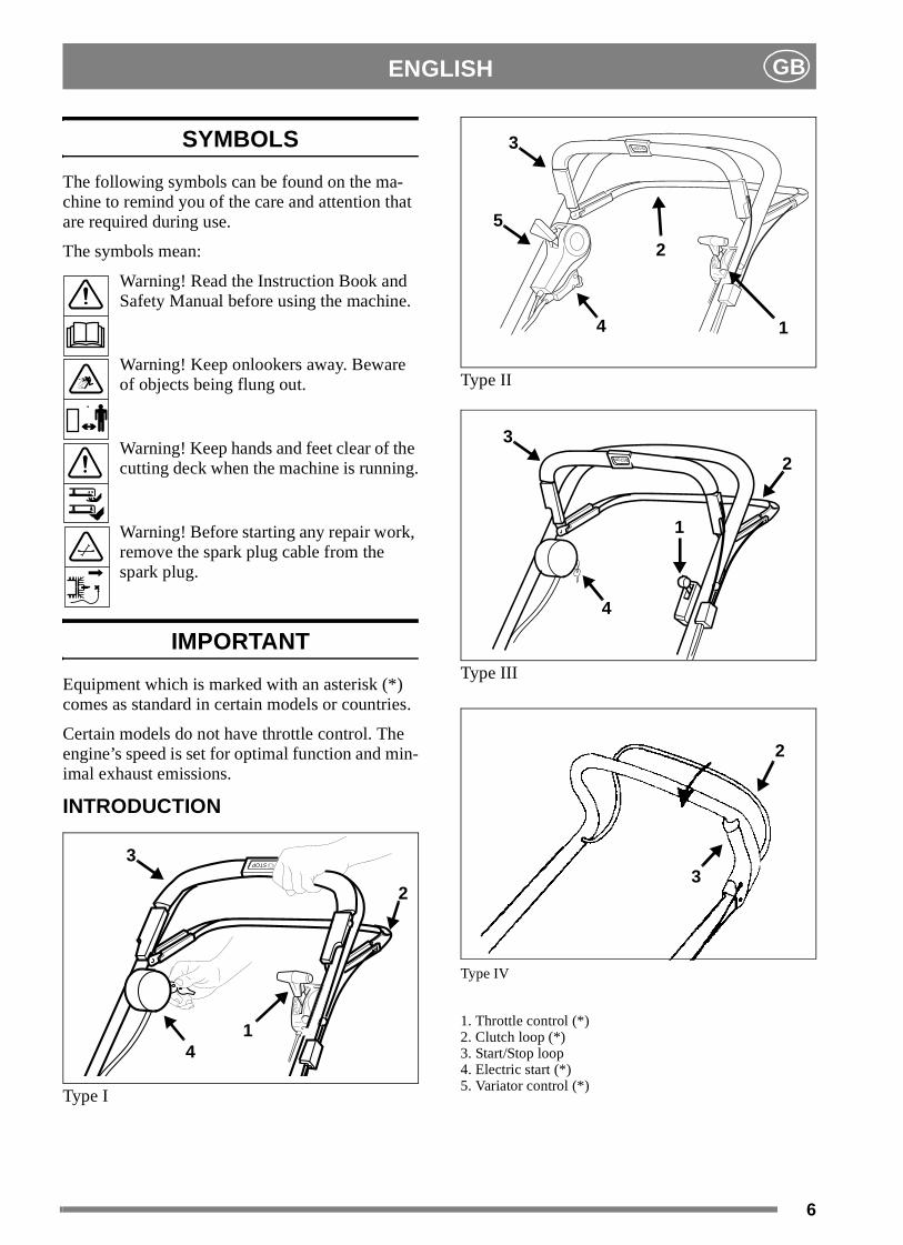
INTRODUCTION
Type I
Type II
Type III
Type IV
1. Throttle control (*)2. Clutch loop (*)3. Start/Stop loop4. Electric start (*)5. Variator control (*)
STOP
14
3
2
4
3
2
5
1
STOP
3
4
1
2
3
2

7
ENGLISHGB
INSTALLATION
LOOSE PARTS IN THE BOX
2 brackets for the grass collector4 screws for the brackets1 ignition key (*)1 battery charger (*)1 Allen key1 socket wrench+ Instruction books
HANDLE(Type I-III)
1. Fold up the lower part of the handle.
2. Install the upper part of the handle mounts usingscrews, washers and locking wheels. A lug isinstalled on the right hand side for the starterhandle (fig. 1).
3. Then tighten the locking wheels onto the lowerpart of the handle. When these have been tight-ened, the height of the handle can be adjusted bytightening the screws B with the wrench provid-ed. (fig. 2)
HANDLE(Type IV)
1. Unscrew the locking wheels from the chassisand secure the lower part of the handle ontoscrews B (fig. 3).
2. Secure the upper part of the handle with wash-ers and locking wheels. There is a lug on theright hand side for the starter handle (fig. 1).
3. Then tighten the locking wheels onto the lowerpart of the handle. When these have been tight-ened, the height of the handle can be adjustedby tightening the screws B with the wrench pro-vided. (fig. 3)
ENGINE BRAKE CABLE
Secure the engine brake cable to the engine brake(fig. 4). Note that the cable should be installed inthe direction of the handle.
CABLE HOLDER
Secure the cables in the cable holders (fig. 5):
D: Start/Stop cable + Clutch cable (*)E: Throttle cable (*) + Clutch cable (*)F: Electric cable (*) + Variator cable (*)
VARIATOR CONTROL (*)
When the mower is delivered, the variator cable isset so that the transmission cannot be damaged.The cable may need tightening, see under heading“ADJUSTING VARIATOR CABLE“ in the sec-tion “MAINTENANCE“.
GRASS COLLECTOR
Raise the collector flap and attach the two bracketsto the grass collector with the screws provided.The brackets are marked with L and R and shouldbe installed at the corresponding mark on the rearof the mower (fig. 7).
Fabric grass collector (*): Fit the fabric bag overthe steel frame and then snap the bag onto the plas-tic lid (fig. 6).
Plastic grass collector (*): Snap together bothhalves and then the upper part (fig. 8).
Open the flap on the machine and attach the grasscollector to the brackets.
NOTE! The lawnmower can be operated withoutthe grass collector. The grass is then left in a linebehind the machine.
BATTERY (*)
The electrolyte in the battery is toxicand corrosive. It can cause serious cor-rosion damage etc. Avoid all contactwith skin, eyes and clothing.
Before starting for the first time the battery shouldbe charged for 24 hours, see further informationunder the heading MAINTENANCE, BATTERY.
Insert ignition key (*) into the ignition lock.
USING THE MOWER
COMBI(*)
Your new lawnmower combines two differentfunctions in the same machine:
1. “MULTICLIP“
The machine comes equipped with a plug (P), in-stalled in the ejector opening (fig. 31). The ma-chine can be used for ‘Multiclip’ i.e. the bladefinely cuts up the grass during mowing. The grassthen falls into the lawn where it is allowed to rot.This provides the lawn with nourishment.

8
ENGLISH GB
To remove the plug, press in the catch (S). On re-installing the plug ensure that both pins are pressedfirmly into the holes so that the plug snaps in place.
Turbo 43 Combi:To remove the plug, unscrew the wing nut.
2. COLLECTION
Assemble the grass collector provided (fig. 6, 8).Open the flap, remove the plug and instead hookthe collector onto the rear of the machine.
When mowing, the grass is collected in the collec-tor. Empty the grass onto the compost heap orspread it over borders as fertiliser. The machine isalso ideal for collecting up leaves in the autumn.
BEFORE STARTING
FILL THE CRANKCASE WITH OIL
The lawnmower is delivered withoutany oil in the engine crankcase. Thecrankcase must be filled with oil beforethe engine is started for the first time.
Remove the oil dipstick (fig. 9, 10, 11). Fill the en-gine’s crankcase with 0.55 litres of good quality oil(service class SE, SF or SG). Use SAE 30 or SAE10W-30 oil.
Slowly fill to ‘FULL/MAX’. Do not overfill.
CHECK THE OIL LEVEL
Check before using the machine that the oil level isbetween ‘FULL/MAX’ and ‘ADD/MIN’ on thedipstick.
Remove and wipe off the dipstick (fig. 9, 10, 11).Slide it down completely and tighten it. Unscrewand pull it up again. Read off the oil level. If the oillevel is low, fill with oil up to the ‘FULL/MAX’mark.
FILL UP THE PETROL TANK
Never remove the filler cap or fill withpetrol while the engine is running or stillwarm.
Never completely fill the petrol tank. Al-low a little room for the petrol to expandif necessary.
Preferably use environmentally friendly petrol, i.e.alkylate petrol. This type of petrol has a composi-tion that is less harmful to people and nature. It hase.g. no lead additives, no oxygenators (alcoholsand ethers), no alkenes and no benzene.
NOTE! If you change to environmental-ly friendly petrol in an engine previouslyrun on ordinary lead-free petrol (95),the petrol manufacturer’s recommenda-tions must be followed carefully.
Ordinary lead-free 95 octane petrol can also beused. You must never use 2-stroke petrol mixedwith oil. NOTE! Bear in mind that lead-free petrolis a perishable; do not purchase more petrol thancan be used within thirty days.
STARTING THE ENGINE(Briggs & Stratton)
1. Place the lawnmower on flat, firm ground. Donot start in long grass.
2. Make sure the spark plug cable is connected tothe spark plug.
3. If the lawnmower is equipped with throttle con-trol, set the throttle control B to full throttle(fig. 15).
4. When starting a cold engine: Press down theprimer fully 6 times (fig. 12, 13).
When starting a warm engine, the primer doesnot need to be used. If the engine stops due to alack of petrol, refill and press down the primer3 times.
5. Press in the Start/Stop loopG towards the han-dle. NOTE! The Start/Stop loopG must be keptpressed in to prevent the engine stopping(fig. 15).
6a Manual start: Grasp the starter handle and startthe engine by pulling briskly on the starter cord.
6b Electric start (*): Start the engine by turning theignition key clockwise. Release the key as soonas the engine starts. Always make short at-tempts at starting in order to prevent discharg-ing the battery.
For ease of starting, press down the handle sothat the front wheels lift slightly from theground. Do not start in thick grass.
7. For the best mowing results, the engine shouldalways be driven at full throttle.
Keep hands and feet away from the ro-tating blade(s). Never put your hand orfoot under the blade casing or in thegrass ejector while the engine is run-ning.

9
ENGLISHGB
STARTING THE ENGINE (Honda)
1. Place the lawnmower on flat, firm ground. Donot start in long grass.
2. Make sure the spark plug cable is connected tothe spark plug.
3. Open the fuel tap (fig. 14).
4. Set the throttle control B in the choke posi-tion . NOTE! It is not necessary to use thechoke position when the engine is warm (fig.15).
5. Press the Start/Stop loopG towards the handle.NOTE! The Start/Stop loopG must be keptpressed in to prevent the engine stopping (fig.15).
6. Grasp the starter handle and start the engine bypulling briskly on the starter cord.
7. When the engine starts, move the throttle con-trol backwards until max. revs are obtained.NOTE! The engine should always be run atmaximum revs to avoid abnormal machine vi-brations.
Keep hands and feet away from the ro-tating blade(s). Never put your hand orfoot under the blade casing or in thegrass ejector while the engine is run-ning.
STOPPING THE ENGINE
The engine may be very warm immedi-ately after it is shut off. Do not touch thesilencer, cylinder or cooling flanges.This can cause burn injuries.
1. Release the Start/Stop loopG (fig. 15) to stopthe engine. This loop must not be disengaged(e.g. by setting it in the depressed positionagainst the handle), as it will not be possible tostop the engine.
Honda: Close the fuel tap.
2. If the lawnmower is left unattended, remove thespark plug cable from the spark plug. Also re-move the ignition key (*).
If the start/stop loop ceases to work, stopthe engine by removing the spark plugcable from the spark plug. Immediatelytake the lawn mower to an authorisedworkshop for repair.
REAR WHEEL DRIVE (*)
Engage the drive by pressing the clutch loop I to-wards the handle. Disengage the drive by releasingthe clutch loop I (fig. 15).
SPEED (*)
Do not touch the variator control whenthe engine is not running. This can dam-age the operation of the variator.
Set to a suitable speed by moving the variator con-trol to one of the 4 positions (fig. 16).
The various positions have the following speeds:
Position :approx. 2.8 km/hPosition 2: approx. 3.1 km/hPosition 3: approx. 3.6 km/hPosition :approx. 4.5 km/h
CUTTING HEIGHT
Shut off the engine before adjusting thecutting height.
Do not set the cutting height so low thatthe blade(s) come into contact with une-ven ground.
The mower has single-lever control for adjustingthe cutting height. Pull the lever out, and set thecutting height to one of the nine positions best suit-ed to your lawn (fig. 17).
MAINTENANCE
No servicing may be carried out on theengine or lawnmower without first re-moving the spark plug cable from thespark plug.
Stop the engine and remove the sparkplug cable if the mower is to be lifted,e.g. during transportation.
If the lawnmower needs to be tilted, itmust be tilted so that the engine’s sparkplug faces upwards. Tilt the lawnmowerwhen the fuel tank is empty.
CLEANING
After each use the mower should be cleaned. Thisis particularly important on the underside of themower casing. Rinse clean with the garden hose.The mower will then last longer and work better.High-pressure washers should not be used.

10
ENGLISH GB
If grass has dried on to the mower casing, it can bescraped clean. If necessary, touch up the undersidewith paint to prevent rust damage.
Clean the silencer and the surroundingarea regularly to remove grass, dirt andflammable waste products.
Remove the transmission casing by removing thescrews S (fig. 27) and clean around the transmis-sion (*) and drive belts (*) with a brush or com-pressed air once or twice a year.
Once every season, the drive wheels (*) should becleaned internally. Remove both wheels. Clean thegear wheel and the wheel gear rim of grass and dirtusing a brush or compressed air (fig. 18). Replacethe wheel.
COOLING SYSTEM
Before each use, the engine’s cooling system mustbe cleaned. Clean the cylinder’s cooling flangesand air intake of grass remains, dirt, etc.
LUBRICATING DRIVE SHAFT (*)
Once per season, the wedge on the drive shaftshould be greased. Remove the wheel (wheel cap,screw and washer). Then remove the circlip andwasher so that the gear wheel can be removed fromthe shaft. Lubricate the wedge with universalgrease.
Reinstall the wedge (the wedge is installed differ-ently on the right and left side, fig. 19-20). Installthe gear wheel so that the L faces out on the leftside and the R faces out on the right side (machineviewed from the rear).
OIL CHANGE
Replace the oil when the engine is warmand the fuel tank is empty. In order toprevent burns, take care while drainingas the oil is hot.
Change the oil the first time after 5 hours of oper-ation, and subsequently every 50 hours of opera-tion or once a season. Remove the dipstick, tilt themower and let the oil run out into a container. Becareful not to let any oil run on to the grass.
Fill with new oil: Use SAE 30 or SAE 10W-30 oil.The crankcase holds approx. 0.55 litre. Fill untilthe oil reaches the “FULL/MAX“ mark on the dip-stick.
AIR FILTER
A dirty and blocked air filter reduces the engineoutput and increases engine wear.
Briggs & Stratton LS 45 (fig. 21): Carefully re-move the air cleaner so that no dirt falls down intothe carburettor. Remove the expanded plastic filterand wash it in liquid detergent and water. Dry thefilter. Pour a little oil on the filter and squeeze it in.Reinstall the air cleaner.
Clean the filter every three months or after every25 hours of use, whichever occurs first. More fre-quently if the engine is working on dusty ground.
Briggs & Stratton XTE (fig. 22):Loosen the screw and close the cover of the air
cleaner. Carefully remove the filter cartridge.Knock it against a flat surface. Replace the filtercartridge with a new one if it is still dirty.
Clean the filter every three months or after every25 hours of use, whichever occurs first. More fre-quently if the engine is working on dusty ground.
Honda GCV (fig. 23): Remove the cover and takeout the filter. Carefully check the filter for holes orother damage. A broken or damaged filter must be re-placed.
To remove dirt, carefully knock the filter severaltimes against a hard surface or use compressed airfrom the back of the filter to blow-clean. Do not tryto brush the filter clean as this forces dirt down intothe fibres. A very dirty filter should be replaced.
Clean the air filter after every 25 hours of use oronce a season. More frequently if the engine isworking on dusty ground.
SPARK PLUG
Never remove the spark plug or sparkplug cable when checking to see if thereis a spark. Always use an approved testinstrument.
Clean the spark plug regularly (every 100 hours ofrun time). Use a wire brush for cleaning.
Change the spark plug if the electrodes are exces-sively burnt or if the plug is damaged. The enginemanufacturers recommendations are as follows:
Briggs & Stratton: Champion J19LM (RJ19LM),spark gap 0.76 mm.
Honda GCV: NGK BPR6ES,Spark gap 0.7-0.8 mm.

11
ENGLISHGB
BATTERY (*)
The electrolyte in the battery is toxicand corrosive. It can cause serious cor-rosion damage etc. Avoid all contactwith skin, eyes and clothing.
In normal use during the season, the battery ischarged by the engine. If the engine cannot bestarted with the ignition key, it may be because thebattery is 'dead'.
Dismantle the battery by opening the battery cov-er, disconnecting the terminal on the engine and re-moving the battery (fig. 24). Connect the batterycharger (provided) to the battery, then connect thecharger to a wall socket and charge for 24 hours(fig. 25).
After charging, the battery may be reinstalled andthe terminal on the battery connected to the termi-nal on the motor (fig. 26).
The battery charger may not be connected directlyto the engine terminal. It is not possible to start theengine with the charger as the power source andthe charger could be damaged.
WINTER STORAGE
Remove the battery and store it fully charged (seeabove) in a dry, cool place (between 0°C and+15°C). At least once during the winter storage pe-riod, the battery should be maintenance-charged.
Before the start of the season, the battery should becharged once again for 24 hours.
ADJUSTING CLUTCH CABLE (*)
If the drive does not engage when the clutch loopis pressed against the handle, or if the lawnmowerfeels cumbersome or slow, this may be because theclutch in the transmission is slipping. To rectifythis situation, adjust the clutch cable as follows:
1. When the clutch loop is released, it should bepossible to push the mower without any resist-ance. If this is not the case, screw in the nippleT until the mower can be pushed (fig. 28).
2. When the clutch loop ispressed in approx. 2 cm (posi-tion 1), there should be someresistance when pushing thelawnmower. With the clutchloop fully pressed in (position2) it should not be possible topush the mower. Unscrew thenipple T until this position isachieved.
ADJUSTING VARIATOR CABLE (*)
If the speed difference between the settings in thevariator control giving the fastest speed (position 3and ) appears insignificant or nothing at all, thevariator cable might need tightening (fig. 16).
1. Run the mower for a few minutes in position.
2. If the variator cable shows some play in nippleY it needs tightening. Undo the locking nut Xand tighten the cable by unscrewing the nippleY until the cable ceases to show any play.
3. Tighten the locking nut X.
NOTE! Do not stretch the cable beyond the pointwhere there is no play in the nipple Y. If the cable isover-tightened, the drive belt could break and/orother parts of the transmission be damaged. Whensetting after e.g. belt change, always start with thenipple Y completely screwed in.
CHANGING BLADES
Wear protective gloves when changingblades to avoid cutting yourself.
Check the blade system regularly. Checkparticularly the curved area behind theblade edge for traces of wear. If the bladeshows traces of damage it should be re-placed. A worn blade creates imbalanceand can damage the mower.
Always check the blade(s) after a collision. Firstdisconnect the spark plug cable. If the blade sys-tem has been damaged, defective parts should bereplaced. Always use genuine spare parts.
To replace the blade, undo the screw (fig. 29, 30).Fit the new blade so that the stamped logo is turnedup facing the blade holder (not facing the grass).Reinstall as illustrated. Tighten the screw properly.Tightening torque 40 Nm.

12
ENGLISH GB
When replacing the blade, the blade screw shouldalso be replaced.
The guarantee does not cover damage to the blade,blade holder or engine caused by running into ob-stacles.
When replacing the blade, blade holder and bladescrew, always use genuine spare parts. Non-genu-ine spare parts can entail a risk of injury or dam-age, even if they fit the machine.
SHARPENING THE BLADES
Sharpening of the blades must be done by wetmethod grinding, using a whetstone or a grind-stone.
For safety reasons, the blades should not be sharp-ened on an emery wheel. A very high temperaturecould cause the blades to become brittle.
Once the blade has been sharpened, itmust then be balanced to avoid vibra-tion damage.
STORAGE
WINTER STORAGE
Empty the fuel tank. Start the engine and let it rununtil it stops. The same petrol must not remain inthe tank for more than one month.
Tip up the mower and unscrew the spark plug.Pour a tablespoon of engine oil into the spark plughole. Pull out the starter handle slowly so that theoil is distributed in the cylinder. Screw in the sparkplug.
Thoroughly clean the mower and store it indoors ina dry place.
SERVICING
Genuine spare parts are supplied by service work-shops and by many dealers.
A list of these can be found on STIGA’s Internetwebsite at: www.stiga.com.

M O W I N G A H E A D
BOX 1006 · SE-573 28 TRANÅS
w w w. s t i g a . c o m