5500 - valvulas nacional · design: en iso 4126-1/asme viii div.1 / ad 2000-merkblatt a2...
TRANSCRIPT

5500
Catlg.Val.550.Nacional-INGLÉS-2016.indd 1 10/2/16 10:53

2
Production, R+D+i, evolution.
VALVULAS NACIONAL, S.A. was established in Spain in 1976. The main target was to assist the petrochemical and chemical industries emerging in Spain at that time. Right from the start VALVULAS NACIONAL, S.A., has been designing and producing safety valves according to most recognized international standards and norms: API, ASME, ASTM and the European directives 97/23 & 94/9 CE. Our production process is accredited by an ISO 9001-2008 certification.
Our know how and capacity to adapt to the constantly changing demands of the market, made possible the introduction of new products designed for new applications in the market, like THERMOSOLAR PLANTS, where VALVULAS NA-CIONAL has supplied safety valves to more than 16 complete plants all over the world, while at the same time continuously supplying to all the main players in the Spanish petrochemical, chemical and refining industries.
Production capacity.
VALVULAS NACIONAL, S.A. valves’ have their discharge coefficients approved in laboratory tests, in order to guarantee and assure the correct values are being used for every sizing process.
In our Technical sales department we work with a modern software which allows us to verify all the possibilities, and to assure strict fulfillment of all international standards.
VALVULAS NACIONAL, S.A. has established representation agreements with the most important O.E.M. companies in the safety sector of the industry, consolidating us as one of the main companies by product range; design and consulting in new plants or in new process.
Our continuous growth, shows a clear trend, which confirms the integration of our workers to provide first class service to our customers and partners.
Factory & location.
Our facilities are Rubí (Barcelona - Spain), with more than 1.200 m2 are fully prepared for our production activities: machining with modern CNC, assembling and testing. We also have long term agreements with approved workshops, which provides us with flexibility and fast feedback to customers demands, with full quality guarantee which has always been our main target.
Strategic alliances.
Nowadays VALVULAS NACIONAL, S.A. starts an internationalization process, establishing representation agreements in different countries and continents all over the world, with specialized companies that will provide added value in our service towards the end user.
VALVULAS NACIONAL providing safety since 1976 !
The Company
Catlg.Val.550.Nacional-INGLÉS-2016.indd 2 10/2/16 10:53
3
Index
• GENERAL FEATURES 4
• CODIFICATION SYSTEM 5
• PART LIST 6
• BILL OF MATERIALS 7
• ACCESSORIES 8
• GENERAL DIMENSIONS 9
• SAFETY VALVE MAIN COMPONENTS 10
• TECHNICAL INFORMATION 10
OPERATING CHARACTERISTICS TABLE 10
GASES DISCHARGE FLOW 11
STEAM DISCHARGE FLOW 12
LIQUIDS DISCHARGE FLOW 13
• DEFINITIONS (EN ISO 4126-1) 14
Catlg.Val.550.Nacional-INGLÉS-2016.indd 3 10/2/16 10:53
4
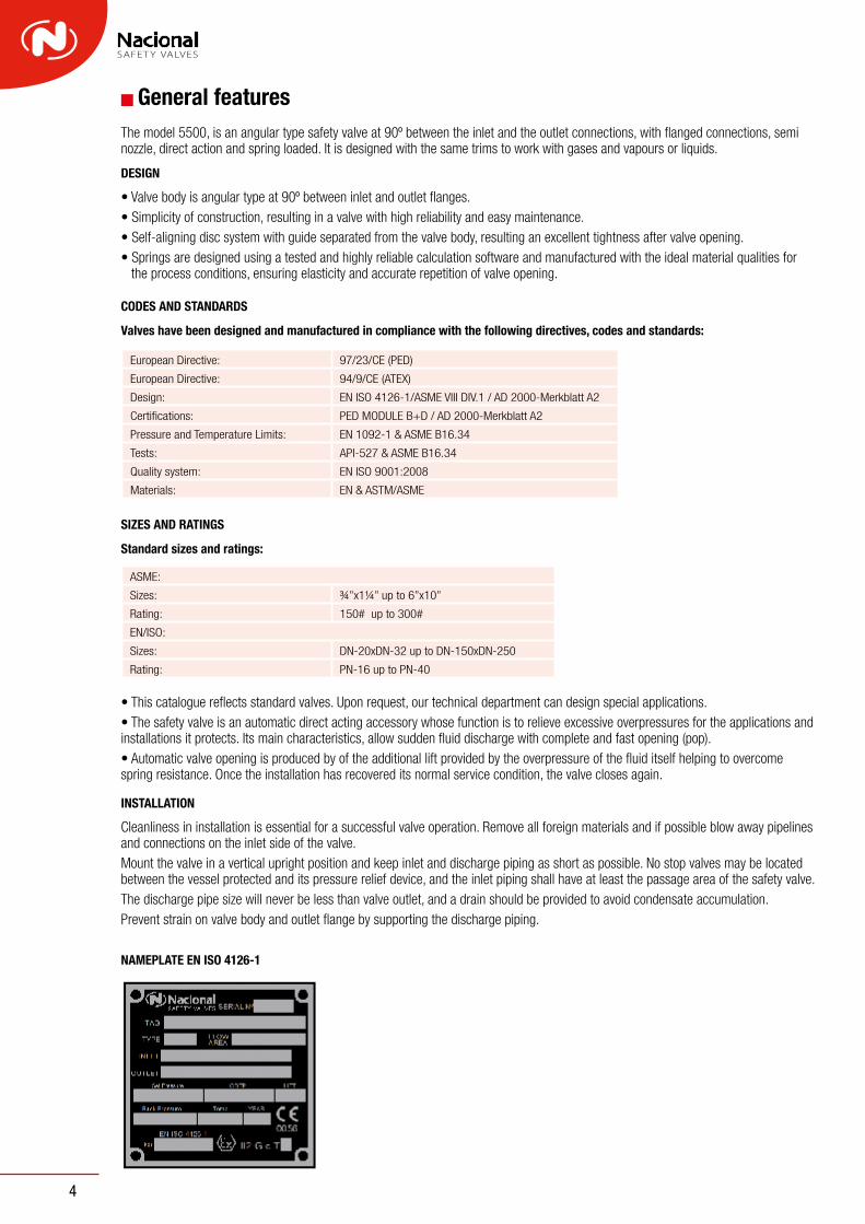
General featuresThe model 5500, is an angular type safety valve at 90º between the inlet and the outlet connections, with flanged connections, semi nozzle, direct action and spring loaded. It is designed with the same trims to work with gases and vapours or liquids.
DESIGN
• Valve body is angular type at 90º between inlet and outlet flanges.• Simplicity of construction, resulting in a valve with high reliability and easy maintenance.• Self-aligning disc system with guide separated from the valve body, resulting an excellent tightness after valve opening.• Springs are designed using a tested and highly reliable calculation software and manufactured with the ideal material qualities for
the process conditions, ensuring elasticity and accurate repetition of valve opening.
CODES AND STANDARDS
Valves have been designed and manufactured in compliance with the following directives, codes and standards:
SIZES AND RATINGS
Standard sizes and ratings:
• This catalogue reflects standard valves. Upon request, our technical department can design special applications.• The safety valve is an automatic direct acting accessory whose function is to relieve excessive overpressures for the applications and installations it protects. Its main characteristics, allow sudden fluid discharge with complete and fast opening (pop).• Automatic valve opening is produced by of the additional lift provided by the overpressure of the fluid itself helping to overcome spring resistance. Once the installation has recovered its normal service condition, the valve closes again.
INSTALLATION
Cleanliness in installation is essential for a successful valve operation. Remove all foreign materials and if possible blow away pipelines and connections on the inlet side of the valve.Mount the valve in a vertical upright position and keep inlet and discharge piping as short as possible. No stop valves may be located between the vessel protected and its pressure relief device, and the inlet piping shall have at least the passage area of the safety valve.The discharge pipe size will never be less than valve outlet, and a drain should be provided to avoid condensate accumulation.Prevent strain on valve body and outlet flange by supporting the discharge piping.
NAMEPLATE EN ISO 4126-1
European Directive: 97/23/CE (PED)
European Directive: 94/9/CE (ATEX)
Design: EN ISO 4126-1/ASME VIII DIV.1 / AD 2000-Merkblatt A2
Certifications: PED MODULE B+D / AD 2000-Merkblatt A2
Pressure and Temperature Limits: EN 1092-1 & ASME B16.34
Tests: API-527 & ASME B16.34
Quality system: EN ISO 9001:2008
Materials: EN & ASTM/ASME
ASME:
Sizes: ¾”x1¼” up to 6”x10”
Rating: 150# up to 300#
EN/ISO:
Sizes: DN-20xDN-32 up to DN-150xDN-250
Rating: PN-16 up to PN-40
Catlg.Val.550.Nacional-INGLÉS-2016.indd 4 10/2/16 10:53

4
General featuresThe model 5500, is an angular type safety valve at 90º between the inlet and the outlet connections, with flanged connections, semi nozzle, direct action and spring loaded. It is designed with the same trims to work with gases and vapours or liquids.
DESIGN
• Valve body is angular type at 90º between inlet and outlet flanges.• Simplicity of construction, resulting in a valve with high reliability and easy maintenance.• Self-aligning disc system with guide separated from the valve body, resulting an excellent tightness after valve opening.• Springs are designed using a tested and highly reliable calculation software and manufactured with the ideal material qualities for
the process conditions, ensuring elasticity and accurate repetition of valve opening.
CODES AND STANDARDS
Valves have been designed and manufactured in compliance with the following directives, codes and standards:
SIZES AND RATINGS
Standard sizes and ratings:
• This catalogue reflects standard valves. Upon request, our technical department can design special applications.• The safety valve is an automatic direct acting accessory whose function is to relieve excessive overpressures for the applications and installations it protects. Its main characteristics, allow sudden fluid discharge with complete and fast opening (pop).• Automatic valve opening is produced by of the additional lift provided by the overpressure of the fluid itself helping to overcome spring resistance. Once the installation has recovered its normal service condition, the valve closes again.
INSTALLATION
Cleanliness in installation is essential for a successful valve operation. Remove all foreign materials and if possible blow away pipelines and connections on the inlet side of the valve.Mount the valve in a vertical upright position and keep inlet and discharge piping as short as possible. No stop valves may be located between the vessel protected and its pressure relief device, and the inlet piping shall have at least the passage area of the safety valve.The discharge pipe size will never be less than valve outlet, and a drain should be provided to avoid condensate accumulation.Prevent strain on valve body and outlet flange by supporting the discharge piping.
NAMEPLATE EN ISO 4126-1
European Directive: 97/23/CE (PED)
European Directive: 94/9/CE (ATEX)
Design: EN ISO 4126-1/ASME VIII DIV.1 / AD 2000-Merkblatt A2
Certifications: PED MODULE B+D / AD 2000-Merkblatt A2
Pressure and Temperature Limits: EN 1092-1 & ASME B16.34
Tests: API-527 & ASME B16.34
Quality system: EN ISO 9001:2008
Materials: EN & ASTM/ASME
ASME:
Sizes: ¾”x1¼” up to 6”x10”
Rating: 150# up to 300#
EN/ISO:
Sizes: DN-20xDN-32 up to DN-150xDN-250
Rating: PN-16 up to PN-40
Catlg.Val.550.Nacional-INGLÉS-2016.indd 4 10/2/16 10:53
5
Codification system
1st DIGIT: Valve model
2nd DIGIT: Inlet nominal size
A: DN 20 G: DN 80
B: DN 25 H: DN 100
C: DN 32 I: DN 125
D: DN 40 J: DN 150
E: DN 50 K: DN 200
F: DN 65 L: DN 250
3rd DIGIT: Outlet nominal size
(Same 2nd Digit)
4th DIGIT: Inlet rating
1: PN 16
2: PN 25
3: PN 40
4: 150 #
5: 300 #
X: OTHERS
5th DIGIT: Outlet rating
(Same 4th Digit)
6th DIGIT: Material
7th DIGIT: Standards accessories
55 A B 1 1 A -1st 2nd 3rd 4th 5th 6th 7th
X0 Packed Lever
X1 Test Gag
X2 Packed lever + Test Gag
X3 Open Bonnet
X4 Open Bonnet + Test Gag
X5 Open Bonnet + Test Gag + Packed Lever
Y4 Plain Lever
Y5 Plain Lever + Test Gag
Z4 Inconel X-750 Spring
W1 Open bonnet + Packed lever
W4 Nozzle with "Stellite"
W5 Disc with "Stellite"
Catlg.Val.550.Nacional-INGLÉS-2016.indd 5 10/2/16 10:53

6
12
30
14
2
4
6
17
5
8
24
23
10
15
11
3
7
18
29
9
13
25
28
1
CONVENTIONAL VALVE PLAIN LEVER
PACKED LEVER
Part list
56
57
60
61
71
70
72
42
51
54
30
5952
55
53
Catlg.Val.550.Nacional-INGLÉS-2016.indd 6 10/2/16 10:53

6
12
30
14
2
4
6
17
5
8
24
23
10
15
11
3
7
18
29
9
13
25
28
1
CONVENTIONAL VALVE PLAIN LEVER
PACKED LEVER
Part list
56
57
60
61
71
70
72
42
51
54
30
5952
55
53
Catlg.Val.550.Nacional-INGLÉS-2016.indd 6 10/2/16 10:53
7
CLASS A B E U
ITEM DENOMINATION -29 to 232 ºC 233 to 400 ºC -268 to 400 ºC -29 to 343 ºC
1 BODY 1.0619 1.0619 1.4408 0.7043
2 BONNET 1.0619 1.0619 1.4408 0.7043
2a OPEN BONNET 1.0619 1.0619 --- 0.7043
3 CAP 1.0619 1.0619 1.4408 0.7043
4 NOZZLE 1.4006 (3) 1.4006 (3) 1.4401 1.4006 (3)
5 DISC 1.4006 (4) 1.4006 (4) 1.4401 1.4006 (4)
6 DISC HOLDER 1.4006 Annealed 1.4006 Annealed 1.4401 1.4006 Annealed
7 ELASTIC RING 1.4401 1.4401 1.4401 1.4401
8 GUIDE 1.4401 (8) 1.4401 (8) 1.4401 1.4401 (8)
9 STEM 1.4021 (5) 1.4021 (5) 1.4401 1.4021 (5)
10 SPRING 50CRV4 C.S. H21 T.S. 1.4401 (1) 50CRV4 C.S. (9)
11 ADJUSTING SCREW 1.4021 (4) 1.4021 (4) 1.4401 Nitrided 1.4021 (4)
12 ADJUSTING SCREW NUT 1.4401 1.4401 1.4401 1.4401
13 SPHERE 1.4021 (6) 1.4021 (6) 1.4401 (2) 1.4021 (6)
14 FRICTION WASHER 1.4401 1.4300 1.4401 1.4401
15 SPRING BUTTON C.S. Zincate C.S. Zincate 1.4401 C.S. Zincate
17 LOCKING RING 1.4401 1.4401 1.4401 1.4401
18 RING 1.4401 1.4401 1.4401 1.4401
23 STUD 1.7225 1.7225 1.4307 1.7225
24 NUT 1.1181 1.1181 1.4307 1.1181
25 PLUG C.S. Zincate C.S. Zincate 1.4305 C.S. Zincate
28 PLUG GASKET Compressed Fibers Graphite Compressed Fibers (7) Compressed Fibers
29 GUIDE GASKET Compressed Fibers Graphite Compressed Fibers (7) Compressed Fibers
30 CAP GASKET Compressed Fibers Graphite Compressed Fibers (7) Compressed Fibers
43 PIN C.S. C.S. C.S. C.S.
51 LEVER CAP 1.0619 1.0619 1.4408 0.7043
52 LEVER STEM 1.4021 (5) 1.4021 (5) 1.4401 1.4021 (5)
53 NUT C.S. Zincate C.S. Zincate 1.4401 C.S. Zincate
54 NUT 1.4401 1.4401 1.4401 1.4401
55 CAM 1.4404 1.4404 1.4404 1.4404
56 LEVER SHAFT 1.4021 (3) 1.4021 (3) 1.4401 1.4021 (3)
57 PACKING BRAID GRAPHITE
59 LEVER C.S. Zincate C.S. Zincate C.S. Zincate C.S. Zincate
60 NUT C.S. - DIN 934 C.S. - DIN 934 1.4301 C.S. - DIN 934
61 PACKING GLAND C.S. Zincate C.S. Zincate 1.4401 C.S. Zincate
70 OPEN LEVER CAP 0.6025 0.6025 - 0.7043
71 OPEN CAP LEVER C.S. Zincate C.S. Zincate - C.S. Zincate
72 OPEN CAP SHAFT 1.4021 (5) 1.4021 (5) - 1.4021 (5)
Bill of materials
(1) Inconel X-750 material for T>300ºC(2) Nitriding surface treatment(3) Quenched and Tempered HB 220 ÷ 280(4) Quenched and Tempered HB 350 ÷ 400(5) Quenched and Tempered HB 240 ÷ 300
(6) Quenched and Tempered HRC>50(7) Graphite material for T>232ºC and T<-29ºC(8) For DN≥50x80: Made of CF8M S.S. casting(9) H21 T.S. material for T>232ºC
Catlg.Val.550.Nacional-INGLÉS-2016.indd 7 10/2/16 10:53

8
Accesories
PACKED LEVER PLAIN LEVER
TEST-GAG
HEATING JACKET
Catlg.Val.550.Nacional-INGLÉS-2016.indd 8 10/2/16 10:53

8
Accesories
PACKED LEVER PLAIN LEVER
TEST-GAG
HEATING JACKET
Catlg.Val.550.Nacional-INGLÉS-2016.indd 8 10/2/16 10:53
9
Orifice(ø mm)
Rating Inlet OutletFlow Area
(cm2)
General Dimensions Standard Lever
A B C E F Weight - (Kg)
180.7043 (D.I.) PN16÷25÷40
xPN16
DN20 DN32 2,54 85 95 294 90 339 7,3 81.0619 (C.S.)
1.4408 (S.S.)23
0.7043 (D.I.) PN16÷25÷40x
PN16DN25 DN40 4,15 105 100 344 90 389 10,4 11,11.0619 (C.S.)
1.4408 (S.S.)29
0.7043 (D.I.) PN16÷25÷40x
PN16DN32 DN50 6,61 115 110 396 90 446 13,2 141.0619 (C.S.)
1.4408 (S.S.)37
0.7043 (D.I.) PN16÷25÷40x
PN16DN40 DN65 10,75 140 115 479 90 529 17,9 18,61.0619 (C.S.)
1.4408 (S.S.)47
0.7043 (D.I.) PN16÷25÷40x
PN16DN50 DN80 17,35 150 120 561 100 611 24,8 25,81.0619 (C.S.)
1.4408 (S.S.)60
0.7043 (D.I.) PN16÷25÷40x
PN16DN65 DN100 28,27 170 140 682 120 732 40,5 41,71.0619 (C.S.)
1.4408 (S.S.)75
0.7043 (D.I.) PN16÷25÷40x
PN16DN80 DN125 44,18 195 160 732 120 792 43,8 45,21.0619 (C.S.)
1.4408 (S.S.)95
0.7043 (D.I.) PN16÷25÷40x
PN16DN100 DN150 70,88 220 180 896 150 956 96,7 98,81.0619 (C.S.)
1.4408 (S.S.)106
0.7043 (D.I.) PN16÷25÷40x
PN16DN125 DN200 88,25 250 200 996 150 1066 124,5 127,31.0619 (C.S.)
1.4408 (S.S.)125
0.7043 (D.I.) PN16÷25÷40x
PN16DN150 DN250 122,72 285 225 1159 150 1229 155,5 159,81.0619 (C.S.)
1.4408 (S.S.)
General Dimensions
(D.I.) Ductile Iron (C.S.) Carbon Steel (S.S.) Stainless Steel
EC
A
B
F
Catlg.Val.550.Nacional-INGLÉS-2016.indd 9 10/2/16 10:53

10
Safety valve main components
SAFETY VALVE MODEL 5500
SERVICE GAS LIQUID
DISCHARGE COEFFICIENT(at 10% of overpressure) (1) (2) Kd 0,90 0,70
BLOWDOWN MAX. -10% (4) -20% (5)
MIN. -5% -10%
SUPERIMPOSED BACK PRESSURE (3) MAX. 10%
BUILT-UP BACKPRESSURE (3) MAX. 15%
SET PRESSURE TOLERANCE (6) ± 3%
MINIMUM SET PRESSUREASME VIII Div.1 (bar) 1EN ISO 4126-1 (bar) 0,5
(1) or 0,1 bar, whichever is greater(2) Coefficient certificated at the Laboratorio Politecnico di Milano(3) Maximum allowable backpressure without overpressure exceeds 10%(4) or 0,2 bar, whichever is greater(5) or 0,6 bar, whichever is greater(6) or ± 0,15 bar, whichever is greater
Technical Information / Operating technical characteristics table
NOZZLEDISC HOLDER
DISC
BODY
NUTS
STUDS
BONNET
ADJUSTING SCREWCAP
NUT
SPRINGBUTTON
STEM
SPRING
GUIDE
Catlg.Val.550.Nacional-INGLÉS-2016.indd 10 10/2/16 10:53
11
Technical information
Values used in formulas
Flow Nm³/h Temperature 15º C
Overpressure 10% (*) Atmospheric Barckpressure Orificies
Area cm2 ø18 ø23 ø29 ø37 ø47 ø60 ø75 ø95 ø106 ø125
Kg/cm² 2,54 4,15 6,61 10,75 17,34 28,27 44,17 70,88 88,25 122,72
0,5 233 381 607 987 1591 2595 4054 6505 8099 11263
1 300 491 781 1271 2049 3341 5221 8378 10431 14505
1,5 367 600 956 1555 2507 4088 6387 10250 12762 17746
2 434 710 1130 1838 2966 4835 7554 12122 15093 20988
2,5 508 829 1321 2149 3466 5650 8828 14167 17638 24528
3 581 950 1513 2461 3970 6472 10111 16226 20202 28093
3,5 655 1071 1705 2773 4473 7293 11395 18285 22767 31659
4 729 1191 1897 3086 4977 8114 12678 20345 25331 35225
4,5 803 1312 2089 3398 5481 8936 13962 22404 27895 38790
5 877 1432 2281 3710 5985 9757 15245 24464 30459 42356
6 1024 1674 2666 4335 6992 11400 17812 28583 35587 49488
7 1172 1915 3050 4960 8000 13043 20379 32702 40716 56619
8 1319 2156 3434 5584 9008 14686 22945 36821 45844 63750
9 1467 2397 3818 6209 10015 16328 25512 40940 50972 70882
10 1615 2638 4202 6834 11023 17971 28079 45059 56101 78013
11 1762 2879 4586 7458 12031 19614 30646 49177 61229 85145
12 1910 3120 4970 8083 13038 21257 33212 53296 66357 92276
13 2057 3362 5354 8708 14046 22900 35779 57415 71486 99408
14 2205 3603 5738 9333 15054 24543 38346 61534 76614 106539
15 2353 3844 6123 9957 16061 26185 40913 65653 81742 113670
16 2500 4085 6507 10582 17069 27828 43480 69772 86871 120802
17 2648 4326 6891 11207 18077 29471 46046 73891 91999 127933
18 2796 4567 7275 11831 19084 31114 48613 78010 97127 135065
19 2943 4809 7659 12456 20092 32757 51180 82129 102256 142196
20 3091 5050 8043 13081 21100 34399 53747 86248 107384 149328
25 3829 6256 9964 16204 26138 42613 66581 106843 133026 184985
30 4567 7461 11884 19328 31176 50827 79415 127437 158667 220642
35 5305 8667 13805 22451 36214 59042 92248 148032 184309 256299
40 6043 9873 15725 25575 41253 67256 105082 168627 209951 291956
45 6781 11079 17646 28698 46291 75470 117916 189221 235592 327613
50 7519 12285 19567 31822 51329 83684 130750 209816 261234 363270
(*) Minimum overpressure 0,2 bargDifferent temperature to 15º C, multiply by Kt
k values different to k=1,41, multiply by Kc
For other fluids or working conditions use the formulas.
Gases discharge flow / Capacity chart - Air
Catlg.Val.550.Nacional-INGLÉS-2016.indd 11 10/2/16 10:53

12
Values used in formulas
Flow Kg/h
Overpressure 10% (*)
Orificies Area cm2 ø18 ø23 ø29 ø37 ø47 ø60 ø75 ø95 ø106 ø125
Kg/cm² 2,54 4,15 6,61 10,75 17,34 28,27 44,17 70,88 88,25 122,72
0,5 202 330 526 855 1379 2248 3512 5635 7016 9757
1 259 422 673 1094 1765 2878 4497 7216 8984 12494
1,5 314 513 817 1329 2144 3495 5460 8762 10910 15171
2 370 604 962 1565 2524 4116 6430 10319 12848 17866
2,5 433 708 1128 1834 2958 4823 7535 12092 15056 20936
3 486 794 1265 2057 3319 5410 8454 13565 16890 23487
3,5 549 898 1430 2326 3751 6116 9556 15334 19092 26549
4 618 1010 1608 2616 4219 6879 10747 17246 21473 29860
4,5 676 1104 1758 2860 4613 7521 11751 18857 23478 32648
5 733 1198 1908 3104 5006 8162 12753 20464 25479 35431
6 846 1382 2202 3581 5776 9416 14712 23609 29395 40876
7 960 1569 2499 4064 6556 10688 16700 26798 33365 46397
8 1074 1755 2796 4547 7335 11958 18684 29983 37330 51911
9 1188 1941 3092 5028 8111 13223 20661 33154 41279 57403
10 1329 2171 3458 5624 9072 14790 23109 37083 46170 64204
11 1439 2351 3745 6090 9823 16015 25022 40153 49993 69520
12 1552 2536 4040 6570 10597 17277 26994 43318 53934 75000
13 1665 2721 4334 7048 11369 18535 28960 46472 57860 80460
14 1779 2906 4629 7529 12144 19799 30935 49641 61806 85947
15 1893 3092 4925 8010 12920 21064 32912 52814 65756 91440
16 2006 3278 5220 8490 13695 22327 34884 55979 69697 96920
17 2119 3462 5514 8968 14465 23583 36846 59128 73618 102372
18 2287 3736 5951 9679 15612 25453 39768 63817 79456 110491
19 2401 3922 6248 10161 16389 26720 41748 66994 83411 115991
20 2515 4108 6544 10642 17167 27987 43728 70171 87367 121493
25 3077 5028 8008 13023 21007 34248 53511 85869 106912 148672
30 3650 5963 9498 15447 24916 40621 63467 101846 126805 176335
35 4214 6886 10968 17837 28771 46906 73288 117606 146427 203621
40 4851 7926 12625 20532 33119 53995 84364 135380 168557 234394
(*) Minimum overpressure 0,2 barg Saturated steam values For superheated steam, multiply by ks For other fluids or working conditions use the formulas.
Steam discharge flow / Capacity chart - steam
Technical information
Catlg.Val.550.Nacional-INGLÉS-2016.indd 12 10/2/16 10:53
13
Values used in formulas
Flow m³/h
Overpressure 10% (*) Orificies
Area cm2 ø18 ø23 ø29 ø37 ø47 ø60 ø75 ø95 ø106 ø125
Kg/cm² 2,54 4,15 6,61 10,75 17,34 28,27 44,17 70,88 88,25 122,72
1 8,43 13,78 21,94 35,68 57,56 93,84 146,62 235,28 292,94 407,36
2 11,41 18,64 29,69 48,28 77,88 126,97 198,38 318,33 396,35 551,16
3 13,96 22,81 36,33 59,08 95,29 155,36 242,74 389,52 484,98 674,41
4 16,12 26,33 41,95 68,22 110,03 179,39 280,29 449,78 560,01 778,75
5 18,02 29,44 46,90 76,27 123,02 200,57 313,37 502,87 626,11 870,66
6 19,74 32,25 51,37 83,55 134,76 219,71 343,28 550,87 685,87 953,77
7 21,32 34,84 55,49 90,24 145,56 237,32 370,79 595,01 740,82 1030,18
8 22,79 37,24 59,32 96,47 155,61 253,70 396,39 636,09 791,97 1101,31
9 24,18 39,50 62,92 102,32 165,05 269,09 420,44 674,68 840,01 1168,12
10 25,48 41,64 66,32 107,86 173,98 283,65 443,18 711,17 885,45 1231,31
11 26,73 43,67 69,56 113,12 182,47 297,49 464,81 745,88 928,67 1291,40
12 27,92 45,61 72,65 118,15 190,59 310,72 485,48 779,05 969,96 1348,83
13 29,06 47,48 75,62 122,98 198,37 323,41 505,30 810,86 1009,57 1403,90
14 30,15 49,27 78,47 127,62 205,86 335,61 524,37 841,47 1047,68 1456,90
15 31,21 51,00 81,23 132,10 213,08 347,39 542,78 871,00 1084,45 1508,03
16 32,24 52,67 83,89 136,43 220,07 358,79 560,58 899,57 1120,02 1557,49
17 33,23 54,29 86,47 140,63 226,84 369,83 577,83 927,25 1154,49 1605,43
18 34,19 55,86 88,98 144,71 233,42 380,55 594,59 954,14 1187,96 1651,97
19 35,13 57,40 91,42 148,67 239,81 390,98 610,88 980,28 1220,51 1697,24
20 36,04 58,89 93,79 152,54 246,04 401,14 626,75 1005,75 1252,22 1741,33
21 36,93 60,34 96,11 156,30 252,12 411,04 642,23 1030,58 1283,14 1784,33
22 37,80 61,76 98,37 159,98 258,05 420,71 657,34 1054,84 1313,34 1826,32
23 38,65 63,15 100,58 163,58 263,85 430,17 672,11 1078,54 1342,85 1867,37
24 39,48 64,51 102,74 167,10 269,53 439,42 686,57 1101,74 1371,74 1907,53
25 40,30 65,84 104,86 170,54 275,09 448,48 700,73 1124,46 1400,02 1946,86
26 41,09 67,14 106,94 173,92 280,53 457,36 714,60 1146,73 1427,75 1985,42
27 41,88 68,42 108,98 177,23 285,88 466,08 728,22 1168,57 1454,95 2023,24
28 42,64 69,68 110,98 180,48 291,12 474,63 741,58 1190,02 1481,65 2060,37
29 43,40 70,91 112,94 183,68 296,28 483,03 754,70 1211,08 1507,87 2096,84
30 44,14 72,12 114,87 186,82 301,34 491,29 767,61 1231,78 1533,65 2132,68
31 44,87 73,31 116,77 189,91 306,32 499,41 780,29 1252,15 1559,00 2167,94
32 45,59 74,49 118,64 192,95 311,23 507,40 792,78 1272,18 1583,95 2202,63
33 46,30 75,64 120,48 195,94 316,05 515,27 805,07 1291,91 1608,50 2236,78
34 46,99 76,78 122,29 198,88 320,80 523,02 817,18 1311,33 1632,69 2270,41
35 47,68 77,90 124,08 201,79 325,49 530,65 829,11 1330,48 1656,53 2303,56
36 48,35 79,00 125,84 204,65 330,10 538,18 840,87 1349,35 1680,03 2336,24
37 49,02 80,09 127,57 207,47 334,66 545,60 852,47 1367,97 1703,20 2368,46
38 49,68 81,17 129,28 210,26 339,15 552,93 863,91 1386,33 1726,06 2400,26
39 50,33 82,23 130,97 213,01 343,58 560,16 875,21 1404,45 1748,63 2431,63
40 50,97 83,28 132,64 215,72 347,96 567,29 886,36 1422,34 1770,90 2462,61
(*) Minimum overpressure 0,2 barg The results shown correspond to calculations for water at 20ºC For different relative densities of water to 1, multiply by Kg For other fluids or working conditions use formulas.
Technical information
Liquids discharge flow / Capacity chart - liquids
Catlg.Val.550.Nacional-INGLÉS-2016.indd 13 10/2/16 10:53

14
Definitions (EN ISO 4126-1)
Blowdown: The difference between the set and re-seating pressures, normally stated as a percentage on the set pressure of a safety
valve except for pressures of less than 3 bar when it is expressed to operate.
Built-up back pressure: The pressure existing at the outlet of the safety valve caused by flow through the valve and the discharge
system
Coefficient of discharge: The value of actual flowing capacity (from tests).
Cold differential test pressure: The inlet static pressure at which a safety valve is set to initiate to open on the test bench. This test
pressure includes corrections for service conditions, as back pressure and/or temperature.
Flow area: The minimum cross-sectional flow area (but not the curtain area) between inlet and nozzle which is used to calculate the
theoretical flow to discharge.
Flow diameter: The diameter corresponding to the flow area.
Lift: The actual travel of the valve disc starting from the closed position.
Maximum allowable pressure: The maximum pressure for which the equipment is designed as specified by the manufacturer.
Overpressure: A pressure increase over the set pressure, at which the safety valve achieves the lift specified by the manufacturer,
usually expressed as a percentage of the set pressure.
Pressure: The pressure unit used in this standard is the bar (1 bar = 105 Pa). It is quoted as gauge (relative to atmospheric pressure)
or absolute as appropriate.
Relieving pressure: The pressure used for the sizing of the safety valve which is greater than or equal to the set pressure plus the
overpressure.
Re-seating pressure: The value of the inlet static pressure at which the disc re-establishes contact with the seat or at which the lift becomes
zero.
Safety valve: Valve which automatically, without the assistance of any energy other than that of the fluid concerned, discharges a
quantity of the fluid so as to prevent a predetermined safe pressure being exceeded and which is designed to re-close and prevent further
flow or fluid after nominal pressure conditions of service have been restored.
Set pressure: The predetermined pressure at which a safety valve under operating conditions initiates to open.
Superimposed back pressure: The pressure existing at the outlet of the safety valve at the time when the device is required to operate.
Catlg.Val.550.Nacional-INGLÉS-2016.indd 14 10/2/16 10:53
VALVE 5500Safety valve specially designed to work
with gases, vapor or liquids for industrial applications.
Catlg.Val.550.Nacional-INGLÉS-2016.indd 15 10/2/16 10:53

Member of Pekos group
www.valvulasnacional.com
Catlg.Val.550.Nacional-INGLÉS-2016.indd 16 10/2/16 10:53
C/ Compositor Vivaldi, 2 - 8 - Pol. Ind Can Jardí 08191 Rubí (Barcelona) Spain
Tel.: +34 936 995 200