5500/7500 iom 8.5 x 11 - mp-gps. · pdf fileimpeller diameter installed bearing material ... a...
TRANSCRIPT

Fybroc® series 5500/7500
I N S T A L L A T I O N M A N U A L
vertical and cantilever pumps
MET-PROA Met-Pro Fluid Handling Technologies Business
Combining the Resources of Dean Pump, Fybroc & Sethco
Global Pump Solutions

Ordering replacement parts
INDEX
Page Page
Fybroc Warranty . . . . . . . . . . . . . . . . . . . . . . . .2 Maintenance . . . . . . . . . . . . . . . . . . . . . . .7Installation Instruction . . . . . . . . . . . . . . . . . . . .3 Disassembly, 5500 Series . . . . . . . . . . . . .7
General . . . . . . . . . . . . . . . . . . . . . . . . . . . .3 Disassembly, 7500 Series . . . . . . . . . . . . .8Pump Installation . . . . . . . . . . . . . . . . . . . .3 Typical Vertical Installation Drawing . . . . . . .10Impeller Adjustment - ALL MODELS . . . . . .3 Sectional Drawings . . . . . . . . . . . . . . . . . . . .11Motor Assembly . . . . . . . . . . . . . . . . . . . . .4 5500 Series, Group I . . . . . . . . . . . . . . . .11Rotation Check . . . . . . . . . . . . . . . . . . . . . .4 5500 Series, Group II . . . . . . . . . . . . . . .12Piping the Pump . . . . . . . . . . . . . . . . . . . . .4 5500 Series, Group III . . . . . . . . . . . . . . .13Bearings and Lubrication . . . . . . . . . . . . . .4 7500 Series . . . . . . . . . . . . . . . . . . . . . . .14Starting the Pump . . . . . . . . . . . . . . . . . . . .5 Notes . . . . . . . . . . . . . . . . . . . . . . . . . . . . . . .15Trouble Check List . . . . . . . . . . . . . . . . . . .6
For future reference fill in the following information from the pump nameplate.This will be necessary to ensure accuracy when ordering replacement parts.
ModelSizeSerial NumberImpeller Diameter InstalledBearing MaterialMaterial of Construction

2
FYBROC pumps are warranted by the Company, insofar as the same are of its own manu-facture, against defects in materials and workmanship under proper and normal use andservice, for a period of one year from the date of original shipment from the factory.FYBROC’s obligation is limited, however, to furnishing without charge, F.O.B. its factory,new parts to replace any similar parts of its own manufacture so proving defective withinsaid period, provided the Buyer has given FYBROC immediate written notice upon discov-ery of such defect. No allowance will be made for labor charges. FYBROC shall have theoption of requiring the return of the defective material, transportation prepaid, to establishthe claim.
FYBROC makes no warranty or guarantee whatsoever, either express or implied, of primemover, starting equipment, electrical apparatus, parts or material not manufactured byFybroc, except to the extent that warranty is made by the manufacturer of such equipmentand material.
FYBROC assumes no liability for damages or delays caused by defective material, and noallowance will be made for local repair bills or expenses without the prior written approvalor authority of FYBROC.
Under no circumstances will FYBROC be liable for indirect, special or consequential loss ordamage of any kind and the Buyer assumes all liability for the consequences of its use ormisuse by the by the Buyer, his employees, or others.
Is at the specified point of rating only and will not cover performance under conditions vary-ing therefrom, nor for sustained performance over any period of time.
If required, shall be conducted in accordance with the practices as set forth in the HydraulicInstitute Standards. The expense of any such tests shall be borne by the buyer.
Are based on shop laboratory tests with cold water as outlined in the Hydraulic InstituteStandards.
Due to the inaccuracies of field testing, the results of any such tests conducted by or forthe Buyer shall be interpreted as being only indicative of the actual field performance of thepump. No equipment will be furnished on the basis of acceptance by results of field tests.If the buyer, after such a test, questions the performance of the pump, he may at his optionrequest a test to establish the performance. Such tests will be conducted in accordancewith the above paragraph entitled “Acceptance Tests.”
Are void if -a. Pipe strains are the cause of damage.b. Pump handles liquids other than those specified in detail.c. NPSH lower than required by pump impeller.d. Operating speed is higher than specified.e. Improper field installation.
To combat corrosion, abrasion, erosion, or pumping solids, foreign objects, or pumping liquids at elevated temperature, any such recommendations will be based on the bestavailable experience of FYBROC and the supplier of the material and industry, BUT WILLNOT CONSTITUTE A GUARANTEE AGAINST THESE EFFECTS.
The foregoing warranty is made in lieu of all other warranties guarantees, obligations orliabilities, expressed or implied, by FYBROC or its representatives. All statutory or impliedwarranties, other than of title, are hereby expressly negated and excluded.
All illustrations and provisions in specifications are descriptive and are not intended as warranties. Penalty of any kind are not acceptable unless approved in writing by an officerof Met-Pro Corporation.
Warranty
perFOrmance
guarantee
acceptance
tests
perFOrmance
representatiOns
Field testing
all Warranties
recOmmendatiOns
FOr special
materials
MET-PROA Met-Pro Fluid Handling Technologies Business
Combining the Resources of Dean Pump, Fybroc & Sethco
Global Pump Solutions

3
general descriptiOn
Fybroc vertical (Series 5500) and cantilever (Series7500) pumps are centrifugal wet pit type pumpingunits for installation in a pit or a tank vented toatmospheric pressure. All pump parts in contactwith the fluid are constructed of glass reinforcedvinyl ester (VR-1) or epoxy (EY-1) resin with theexception of the shaft and hardware, which are ofan alloy selected for compatibility with the fluidpumped. Vertical pumps contain one or more non-metallic line bearings which require a source of fluidflush to lubricate and cool the bearings. Cantileverpumps are of the overhung shaft type and do notcontain any bearings below the mounting plate.
pump installatiOn
1) Inspect pump and any accessories packed with the unit to assure no damage has occurred during transit.
MOTORS ARE SHIPPED SEPARATELY AND SHOULD ALSO BE INSPECTED.
Install the pump assembly in the pit before mounting the motor to prevent damage.
2) WHEN HANDLING THE PUMP UNIT, IT ISVERY IMPORTANT TO PICK UP THE UNITBY THE TOP.
A rope or sling should be attached to the bearing pedestal (Item 81) or the mounting plate (Item 89). Serious damage may result if the unit is picked up by the column shaft (Item 91) or discharge pipe (Item 95). The pump assembly must be lowered carefully into the pit. Care must be taken to guide the pump as it is lowered into the pit to avoid striking the sides.
3) When the mounting plate is resting in the proper position, check the level of the plate, and shim if necessary to level the unit. The pump shaft must be vertical to avoid a bending stress on the shaft column, and to avoid bearing damage during operation. Check the shaft column (Item 91) with a level to be sure the unit is straight and plumb.
4) Bolt down the mounting plate, and be sure it is supported on all four sides. there should
be a minimum of 4 to 12 inches between
INSTALLATION 5500 SERIES AND 7500 SERIES PUMPS
the bottom of the suction strainer, and
the bottom of the tank of pit. For higher flow pumps, this clearance may be specified as greater; check your outline drawing.
5) Be sure the source of lubrication to the line bearings on 5500 Series vertical pumps has been connected if an external flush source is required. Check all fittings at the line bearings to be sure no damage has occurred during shipment.
6) Connect level control, if the pump is so equipped.
impeller adjustment - all mOdels
ALL MODELS ARE PREADJUSTED BEFORELEAVING THE FACTORY. CHECK TO SEE IFSHAFT TURNS FREELY BY HAND. IF NO BINDING IS NOTED, NO FURTHER ADJUST-MENT IS NEEDED. IF BINDING IS NOTED, FOLLOW ADJUSTMENT PROCEDURE BELOW.NEVER ADJUST IMPELLER WITH COUPLINGCONNECTED.
The impeller must be adjusted with the pumpmounted in the vertical position.
Impeller Adjustment for 5500 Series Vertical Sizes:1x11/2x6, 11/2x3x6, 2x3x6, 1x11/2x8, 11/2x3x8,2x3x8, 3x4x8, 11/2x3x10, 2x3x10, 3x4x10, 4x4x10
1) Loosen bearing cap set screw (Item 12A).
2) Loosen clamping screw in adjusting collar (Item 66).
3) Slowly rotate adjusting collar counterclock-wise while pushing down on shaft, and rotate shaft until you feel the impeller touch the casing face.
4) Place a dial indicator on the end of the shaft.Rotate the collar clockwise (CW), raising the shaft to the clearance specified in Table 1. NOTE: For “Quick Field” adjustment, rotate the collar 90° clockwise, while securing the shaft.
5) Re-lock adjusting collar clamping screw (Item 66).
6) Tighten set screw (Item 12A).

7) Rotate shaft by hand to insure that there is nobinding or rubbing of parts.
Impeller Adjustment for Vertical Sizes: 4x6x10, 2x3x13, 3x4x13, 4x6x13, 6x8x13,8x10x15, 10x12x16 and ALL CANTILEVER SIZES
1) Loosen three adjusting screws (Item 37C)evenly.
2) Tighten up equally on outer screw (Item 37A)until you can feel the impeller just starting torub on the casing face. Rotate the shaft frequently while taking up on these bolts, soyou know when it begins to bind.
3) Now loosen the outer screw (Item 37A) evenlyuntil you can insert a feeler gauge, correspon-ding to the impeller clearance from Table 1above, under each of the three bolt heads.NOTE: For “Quick Field” adjustment, loosenouter screw (Item 37A) two flats.
4) Tighten adjusting screw (Item 37C) evenlyuntil the bearing housing is backed up againstthe outer screw (Item 37A).
5) Check to be sure the shaft turns freely.
mOtOr assembly
When the motor is furnished by the customer, themotor coupling half must be installed. Place motoron motor support, start the mounting bolts into themotor, and securely tighten the motor mountingbolts.
rOtatiOn checK
Before coupling sleeve is connected, the motorshould be wired and the direction of rotation checked.The motor should be rotating in a clockwise (CW)direction when looking down on top of the motor.SERIOUS DAMAGE COULD OCCUR IF PUMP ISOPERATED IN THE WRONG DIRECTION.
After the proper motor rotation direction is estab-lished, loosen the motor coupling half and installthe coupling sleeve. Adjust the motor coupling halfand tighten. Rotate the coupling to insure no bind-ing occurs and install the coupling guard.
Proper alignment of the pump and motor is ofextreme importance for trouble free mechanicaloperation. Check the coupling alignment by layinga straight-edge across both coupling hubs at fourpoints, 90 degrees apart.
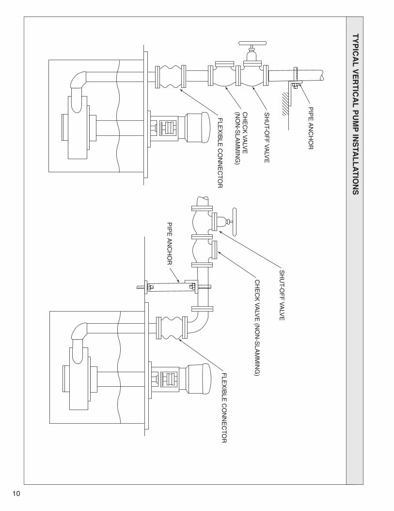
piping the pumpThe pump discharge pipe is connected to theprocess piping above the mounting plate. The pip-ing should be as direct as possible with a minimumnumber of fittings. IT IS RECOMMENDED THAT ACHECK VALVE BE INSTALLED IN THE PUMPDISCHARGE LINE AS CLOSE AS POSSIBLE TOWHERE THE DISCHARGE PIPE COMESTHROUGH THE MOUNTING PLATE. This will pre-vent backflow from the discharge line upon pumpshutdown and reverse rotation of the pump shaft,which could cause serious pump damage. This isparticularly critical when the pump is on level controloperation with frequent start/stop cycles. IT ISALSO HIGHLY RECOMMENDED FOR LONGPUMP LIFE THAT PROPERLY ANCHORED BEL-LOWS TYPE EXPANSION JOINTS BE INSTALLEDAT THE DISCHARGE FLANGE CONNECTION.See Figure E-1-1 on page 10 for typical installations.
PUMP BEARINGS - VERTICAL 5500 SERIES
1) UPPER BALL TYPE (PEDESTAL)
All vertical pumps have one ball type thrustbearing (Item 18) located above the mountingplate. With the exception of sizes 4x6x10,2x3x13, 3x4x13, 4x6x13, 6x8x13 and8x10x15, the bearings are permanently lubri-cated sealed bearings, and require no furtherlubrication. To lubricate the bearing, shut offthe pump and remove the coupling guard.Remove the grease vent plug opposite thegrease fitting. Inject grease through the fittinguntil it appears at the opposite vent hole.Reinstall the coupling guard and run thepump until it reaches operating temperature(approximately 1-2 hours). This will allowexcess grease to purge from the bearing cavity. Shut off the pump and reinstall thegrease vent plug.
table 1
4
Impeller Diameter Clearance
Up to 8" .015"8" to 10" .020"10" to 15" .025"

5
2) LOWER SLEEVE TYPE
5500 Series vertical pumps have one or moresleeve type line shaft bearings (Item 93A).The bearings are nonmetallic and are self-lubricating, but must have continuous cleanliquid injected to flush the bearing surface toclean and cool the bearing. The variousmethods of flushing the bearing (s) aredescribed as follows:
External Clean Flush - In this arrangementthe pump unit is provided with flush tubing toall the line bearings through the mountingplate where a connection is provided for aCONTINUOUS SOURCE OF CLEAN LIQUIDAT A RATE of 1/4 to 1/2 GPM PER BEARINGAT 10-20 PSI. This is the most desirablemethod of bearing flush and will offer thegreatest bearing life.
From the Pump Discharge - Bearings may beflushed in this manner when the pumped fluidis clean and free of solids. The flush tubingcan be connected to the discharge pipe toprovide the lubricating and cooling.
Cyclone Separator - When it is impossible touse an external clean flush and the pumpedfluid is not clean, a cyclone separator may beused. The flush tubing is run from the pumpdischarge to the cyclone separator mountedon top of the mounting plate. The clean fluidout of the separator is run to the line bear-ings, and solids are returned back into thesump. This method will prolong bearing life,but eventual clogging of bearings must beexpected, due to solid buildup. Clean externalflush is the best bearing flush method.
REGARDLESS OF THE METHOD OF BEAR-ING FLUSH, THE FLUSH SYSTEM MUSTBE CHECKED PERIODICALLY TO INSUREFLUID IS BEING SUPPLIED TO ALL THELINE BEARINGS.
PUMP BEARINGS - CANTILEVER 7500 SERIESAll cantilever pumps are provided with two balltype bearings (Items 16 and 18) above the mount-ing plate, which support the shaft. There are nobearings located below the mounting plate.
The two bearings are equipped with grease fittingsfor periodic lubrication. To lubricate the pumpbearings, shut off the pump and remove the cou-pling guard. Remove the grease vent plugs oppo-site the grease fittings. Inject grease through thefitting until it appears at the opposite vent holes.Reinstall the coupling guard and run the pumpuntil it reaches operating temperature (approxi-mately 1-2 hours). This will allow excess grease topurge from the bearing cavity. Shut off the pumpand reinstall the grease vent plugs.
starting the pump
Before the pump is started, turn pump by hand atthe coupling to insure it is free and does not rub orbind, and reinstall the coupling guard. Turn on theflush to the steady bearings if provided from anexternal source.
Inspect the pump casing to be sure it is submergedbefore engaging the motor.
DO NOT operate pump at reduced capacity orwith discharge valve closed. At this point, all energy developed by the pump will convert toheat, which may cause either mechanical damage,or vaporizing of pump liquid in the impeller eye,causing cavitation.
DO NOT operate pump when tank level dropsbelow minimum pump submergence.
DO NOT operate pump if surging occurs.
DO NOT operate pump if motor overloads. This willcause overheating of the motor and possible motordamage.

6
trOuble checK list
Refer to the following diagnostic section ifhydraulic problems are encountered in the pumpoperation.
PROBLEM: No liquid delivered.
CHECK: Priming, casing is not completely filled; no liquid in pit; insufficient submergence.
Speed too low. (Result reduced TDH.)
Impeller eye or suction strainer is completely plugged.
PROBLEM: Not enough liquid delivered.
CHECK: Cavitation.
Air leakage through suction tailpipe.
Speed too low.
Impeller and strainer are plugged.
Impeller clearance too great.
Impeller is damaged.
PROBLEM: Not enough pressure.
CHECK: Cavitation.
Air or gases in liquid.
Impeller diameter too small.
Impeller clearance too great.
Impeller is damaged.
PROBLEM: Pump works awhile, then stops.
CHECK: Float controls.
Insufficient submergence.
Air or gases in liquid.
Impeller eye or strainer plugged.
PROBLEM: Pump takes to much power.
CHECK: Speed too high.
Head is lower than rating; pump-ing beyond design point.
Liquid heavier than specified; check viscosity and specific gravity.
Rotating element binds.
Impeller binding; check clearance.
Check line voltage to motor.
PROBLEM: Pump is noisy.
CHECK: Pump is cavitating.
Pump is running close to shut-off.
Shaft is bent.
Rotating parts bind, are loose or broken.
Bearings are worn out.
Pump and drive misaligned.
Check lock collar on the dischargepipe to be sure it is not putting stress on discharge pipe, causing distortion of pump casing, and thus bending of shaft and column.

7
maintenance
1) Periodically lubricate the upper ball bearing(s)when equipped with grease fittings.
2) Check for noise (mechanical or hydraulic) andvibration.
3) Check float switch operation
4) Check flush line to the line shaft bearings forbuildup.
5) Check discharge pressure gauge periodically.
disassembly - Vertical 5500 series
1) Shut off motor. Shut off all valves controlling flow of liquid from the pump. Disconnect thepower to the motor.
2) Disconnect discharge pipe and flush piping.
3) Unbolt motor and remove from motor support.
4) Remove the pump unit from the pit unless thepit can be drained and the pump can beworked on from the pit.
5) When the pump is lying in the horizontal position, the pump column and shaft shouldbe supported to remove any bending stressfrom the shaft.
6) Disconnect discharge pipe flange at the pumpcasing.
7) Remove casing bolts (Item 1D) and removecasing (Item 1) from cover (Item 11).
8) Fix the pump shaft at the coupling andremove the impeller (Item 2) by turning theimpeller in a counterclockwise (CCW) direc-tion facing the impeller. A strap wrench orsimilar device may be required to disengagethe screw threads. Remove the sleeve cap(Item 14A) and O-ring (Item 14B) if the pumpis so equipped.
9) Shaft removal for sizes: 1x11/2x6, 11/2x3x6, 2x3x6, 1x11/2x8, 11/2x3x8, 2x3x8, 3x4x8,11/2x3x10, 2x3x10, 3x4x10, 4x4x10
a) Remove coupling from the pump shaft and remove slinger (Item 40) and bearing snap ring (Item 12B).
b) Slide pump shaft (Item 6) up through the column and pedestal. If resistance is encountered, tap on the impeller end with asoft mallet, or use wood as a buffer. BE CAREFUL NOT TO DAMAGE SCREW THREADS AT THE IMPELLER END.
c) Remove set screw (Item 12A).
d) Loosen lock screw in the threaded collar (Item 66) and unscrew from shaft.
e) Slide bearing holder and bearing off shaft. If bearing (Item 18) is to be replaced, it must be pressed off the bearing holder (Item 12).
f) Unscrew the shaft sleeve if the pump is so equipped. care must be taken not to mar or
scratch the shaft in removal or handling.
9A) Shaft removal for sizes: 4x6x10, 3x4x13, 6x8x13, 2x3x13, 4x6x13, 8x10x15
a) Remove coupling and outer screws (Item 37A).
b) Turn adjusting screws (Item 37C) clockwisecompletely and jack shaft and bearing assembly until bearing is clear.
c) Pull shaft and bearing assembly through the pedestal.
d) Remove bearing housing snap ring (Item 21A).
e) Slide bearing housing (Item 21) from thrust bearing.
f) Remove snap ring (Item 18B) and press bearing off shaft.
10) Remove the bearing flush line(s) (127).
11) Remove the column-cover nuts (Item 11B) and disengage cover (Item 11) from the column. Note position of cover relative to column flange.
12) Remove cover snap ring and slide cover sleeve bearing (Item 93B) and pin (Item 93D) from the cover.
13) Remove bearing holder nuts (Item 93F) and remove bearing holders (Item 93) from the column. Slide the sleeve bearing (Item 93A) from the bearing holder.
reassembly - Vertical 5500 series
Replace all worn or defective parts as required. Cleanall those to be reused. Reassemble in reverse orderof disassembly, with the following notes:
1) After the shaft is installed in the pedestal andcolumn, adjust the shaft downward, prior to installing the impeller.

8
2) When the impeller (and shaft sleeve, if so provid-ed) is installed, be certain the threads are firmlyseated against the shaft shoulder.
3) After the impeller is installed, adjust the shaftupward until the back of the impeller starts totouch the face of the cover, before the casing isinstalled.
4) With the casing assembled, check dischargepipe and shaft column alignment. Trim or shimthrust collar (Item 41) as required.
5) Adjust impeller as outlined under “IMPELLERADJUSTMENT” (Page 3 and 4).
6) Check motor rotation prior to connecting andadjusting the coupling.
7) Install coupling guard.
disassembly - cantilever 7500 series
1) Shut off all valves controlling flow of liquidfrom the pump. Disconnect the power to themotor.
2) Disconnect discharge pipe.
3) Unbolt motor and remove from motor support.
4) Remove the pump unit from the pit unless thepit can be drained and the pump can beworked on from the pit.
5) When the pump is lying in the horizontal position, the pump column and shaft shouldbe supported to remove any bending stressfrom the shaft.
6) Disconnect discharge pipe flange at the pumpcasing.
7) Remove casing bolts (Item 1D) and removecasing (Item 1) from the cover (Item 11).
8) Fix the pump shaft at the coupling andremove the impeller (Item 2) by turning theimpeller in a counterclockwise (CCW) direc-tion facing the impeller. A strap wrench orsimilar device may be required to disengagethe screw threads.
9) Remove the column-cover nuts (Item 11B)and disengage cover (Item 11) from the column. Note position of cover relative to the column flange.
10) Remove the snap ring (Item 63A) and slidethe restriction bushing (Item 63) and pin (Item63B) from the cover.
11) Remove outer screws (Item 37A).
12) Turn adjusting screws (Item 37C) clockwisecompletely and jack shaft and bearing assem-bly until bearing is clear.
13) Pull shaft and bearing assembly through thepedestal.
14) Remove upper bearing housing snap ring(Item 21B) and slinger (Item 40).
15) Slide bearing housing (Item 21) from thrustbearing (Item 18).
16) Remove snap ring (Item 18B) and pressupper bearing (Item 18) off shaft.
17) Remove lower snap ring (Item 16A) andpress lower bearing (Item 16) off shaft.
18) Remove column to pedestal nuts (item 70H)and remove column (Item 91).
19) Remove pedestal to coverplate screws (Item70B) and remove pedestal (Item 81). Pressgrease seal (Item 47) from pedestal.
reassembly - cantilever 7500 series
Replace all worn or defective parts as required.Clean all those to be reused.
1) Press or shrink lower bearing (Item 16) onshaft and pack bearing with grease. Bearinggrease seal should face motor end of shaft.
2) Install lower snap ring (Item 16A) and slideinternal snap ring (Item 21B) over the shaft.
3) Press or shrink upper bearing (Item 18) onshaft and pack bearing with grease. Bearinggrease seal should face pump end of shaft.
4) Install external snap ring (Item 18B) and slidebearing housing (Item 21) over bearing.
5) Install internal snap ring (Item 21B).
6) Install complete shaft assembly in pedestal(Item 81) and install lower grease seal (Item 47).
7) Back-off adjusting screws (Item 37C) andtighten outer screws (Item 37A). This willadjust shaft in the down position.
8) Fasten pedestal assembly to mounting plate(Item 89).
9) Slide column (Item 91) over shaft, being care-ful not to damage vapor seal (Item 91B) andsecure to pedestal.

9
10) Install restriction bushing (Item 63) with pin (Item 63B) in cover (Item 11) and secure withsnap ring (Item 63A).
11) Assemble casing cover (Item 11) to column (Item 91) using cover nuts (Item 11B). Be sure cover is oriented the same way as removed.
12) Reinstall impeller (Item 2), being certain the impeller threads are firmly seated against theshaft shoulder.
13) Back-off outer screws (Item 37A) and tighten adjusting screws (Item 37C) until impeller starts to rub the face of the casing cover (Item 11).
14) Install casing and discharge pipe assembly. Check discharge column and shaft column alignment. Trim or shim thrust (discharge lock) collar (Item 41) as required.
15) Adjust impeller as outlined under “IMPELLERADJUSTMENT” (Page 4).
16) Lubricate bearings.
17) Check motor rotation prior to connecting and adjusting the coupling.
18) Install coupling guard.
10
PIP
E A
NC
HO
R
SH
UT-O
FF
VA
LVE
CH
EC
K V
ALV
E
(NO
N-S
LAM
MIN
G)
FLE
XIB
LE C
ON
NE
CTO
R
SH
UT-O
FF
VA
LVE
CH
EC
K V
ALV
E (N
ON
-SLA
MM
ING
)FLE
XIB
LE C
ON
NE
CTO
R
PIP
E A
NC
HO
R
ty
pic
al
Ve
rt
ica
l p
um
p in
sta
ll
at
iOn
s

11
5500 s
er
ies
se
ct
iOn
al
dr
aW
ing
- g
rO
up
i V
er
tic
al
pu
mp
s
For Sizes:1x11/2x6, 11/2x3x6, 2x3x6, 1x1
1 /2x8, 1
1 /2x3x8, 2x3x8, 3x4x8, 1x2x10, 1
1 /2x3x10, 2x3x10, 3x4x10, 4x4x10
ITEM
DESCRIPTION
REQUIRED
1Casing . . . . . . . . . . . . . . . . . . . . . . . . . . . . . . . . . . . . .1
1CNut, Casing . . . . . . . . . . . . . . . . . . . . . . . . . . . . . . .8-12
1DBolt, Casing . . . . . . . . . . . . . . . . . . . . . . . . . . . . . . .8-12
1EWasher, Casing . . . . . . . . . . . . . . . . . . . . . . . . . . .16-24
2Impeller . . . . . . . . . . . . . . . . . . . . . . . . . . . . . . . . . . . . .1
2BO-ring, Im
peller . . . . . . . . . . . . . . . . . . . . . . . . . . . . . . .1
6Shaft . . . . . . . . . . . . . . . . . . . . . . . . . . . . . . . . . . . . . . .1
6AKey, Coupling . . . . . . . . . . . . . . . . . . . . . . . . . . . . . . . .1
6BO-ring, Shaft . . . . . . . . . . . . . . . . . . . . . . . . . . . . . . . . .1
11Cover, Casing . . . . . . . . . . . . . . . . . . . . . . . . . . . . . . . .1
11A
Stud, Colum
n - Cover . . . . . . . . . . . . . . . . . . . . . . . . . .8
11B
Nut, Colum
n - Cover
. . . . . . . . . . . . . . . . . . . . . . . . . .8
12Bearing Holder . . . . . . . . . . . . . . . . . . . . . . . . . . . . . . .1
12A
Set Screw, Bearing Holder . . . . . . . . . . . . . . . . . . . .1-2
12B
Snap Ring, Bearing . . . . . . . . . . . . . . . . . . . . . . . . . . .1
14Shaft Sleeve (opt.) . . . . . . . . . . . . . . . . . . . . . . . . . . . .1
14A
Sleeve Cap . . . . . . . . . . . . . . . . . . . . . . . . . . . . . . . . . .1
14B
O-ring Cap
. . . . . . . . . . . . . . . . . . . . . . . . . . . . . . . . . .1
18Ball Bearing . . . . . . . . . . . . . . . . . . . . . . . . . . . . . . . . .1
40Slinger . . . . . . . . . . . . . . . . . . . . . . . . . . . . . . . . . . . . .1
41Lock Collar, Discharge Pipe . . . . . . . . . . . . . . . . . . . . .1
41A
Screw, Lock Collar . . . . . . . . . . . . . . . . . . . . . . . . . .1-2
41B
Screw, Lock Collar - Cover Plate . . . . . . . . . . . . . . .1-2
41C
Washer, Lock Collar- Cover Plate . . . . . . . . . . . . . . .1-2
41D
Spacer, Discharge
. . . . . . . . . . . . . . . . . . . . . . . . . . . .1
66Threaded Collar . . . . . . . . . . . . . . . . . . . . . . . . . . . . . .1
70A
Screw, Colum
n - Pedestal . . . . . . . . . . . . . . . . . . . . .4-8
70B
Screw, Pedestal - Cover Plate . . . . . . . . . . . . . . . . .4-8
70D
Bolt (Stud), Discharge Elbow
. . . . . . . . . . . . . . . . . . . .4
70E
Nut, Discharge Elbow . . . . . . . . . . . . . . . . . . . . . . . . . .4
71D
Adaptor, M
otor . . . . . . . . . . . . . . . . . . . . . . . . . . . . . . .1
73O-ring Cover . . . . . . . . . . . . . . . . . . . . . . . . . . . . . . . . .1
81Pedestal . . . . . . . . . . . . . . . . . . . . . . . . . . . . . . . . . . . .1
82A
Screw, Pedestal - Motor Adaptor . . . . . . . . . . . . . . . . .4
87Strainer . . . . . . . . . . . . . . . . . . . . . . . . . . . . . . . . . . . . .1
87A
Stud, Strainer . . . . . . . . . . . . . . . . . . . . . . . . . . . . . . . .4
87B
Nut, Strainer . . . . . . . . . . . . . . . . . . . . . . . . . . . . . . . . .4
89Cover Plate . . . . . . . . . . . . . . . . . . . . . . . . . . . . . . . . . .1
91Colum
n . . . . . . . . . . . . . . . . . . . . . . . . . . . . . . . . . . . . .1
91B
Vapor Seal . . . . . . . . . . . . . . . . . . . . . . . . . . . . . . . . . .1
93Bearing Holder Set* . . . . . . . . . . . . . . . . . . . . . . . . . . .1
93A
Sleeve Bearing Set* . . . . . . . . . . . . . . . . . . . . . . . . . . .1
93B
Sleeve Bearing Cover
. . . . . . . . . . . . . . . . . . . . . . . . .1
93C
Snap Ring, Sleeve Bearing, Cover
. . . . . . . . . . . . . . .1
93D
Pin, Cover . . . . . . . . . . . . . . . . . . . . . . . . . . . . . . . . . . .1
93E
Stud, Bearing Holder* . . . . . . . . . . . . . . . . . . . . . . . . .2
93F
Nut, Bearing Holder* . . . . . . . . . . . . . . . . . . . . . . . . . .8
95Discharge Pipe . . . . . . . . . . . . . . . . . . . . . . . . . . . . . . .1
95A
Gasket, Discharge Flange . . . . . . . . . . . . . . . . . . . . . .1
95B
Flange, Discharge
. . . . . . . . . . . . . . . . . . . . . . . . . . . .1
99Elbow, Discharge
. . . . . . . . . . . . . . . . . . . . . . . . . . . . .1
100
Tailpipe, Suction . . . . . . . . . . . . . . . . . . . . . . . . . . . . . .1
100A
Gasket, Suction . . . . . . . . . . . . . . . . . . . . . . . . . . . . . .1
100B
Bolt, Tailpipe . . . . . . . . . . . . . . . . . . . . . . . . . . . . . . . . .4
100C
Nut, Tailpipe . . . . . . . . . . . . . . . . . . . . . . . . . . . . . . . . .4
127
Flush Tubing Assem
bly . . . . . . . . . . . . . . . . . . . . . . . .1
* Quantities vary with pum
p setting.
12
5500 s
er
ies
se
ct
iOn
al
dr
aW
ing
- gr
Ou
p ii V
er
tic
al
pu
mp
s
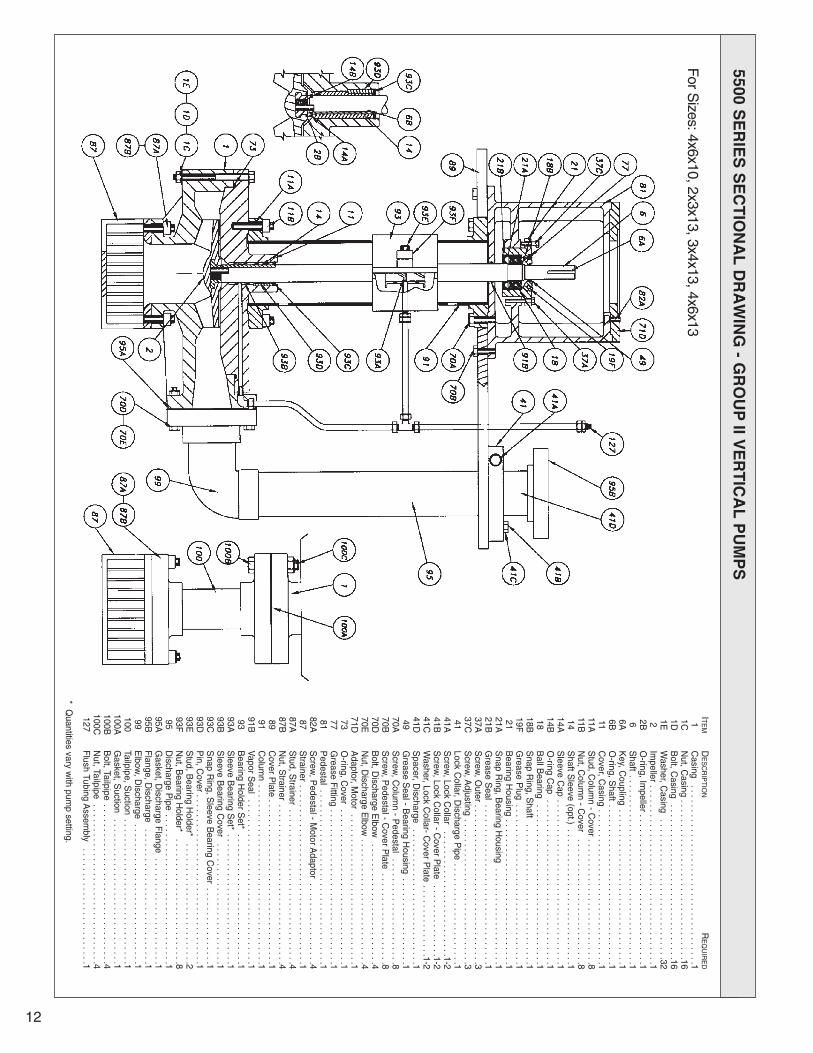
For S
izes: 4x6x10, 2x3x13, 3x4x13, 4x6x13ITEM
DESCRIPTION
REQUIRED
1Casing
. . . . . . . . . . . . . . . . . . . . . . . . . . . . . . . . . . . . .11C
Nut, C
asing . . . . . . . . . . . . . . . . . . . . . . . . . . . . . . . . .161D
Bolt, C
asing . . . . . . . . . . . . . . . . . . . . . . . . . . . . . . . .16
1EWasher, C
asing . . . . . . . . . . . . . . . . . . . . . . . . . . . . .32
2Impeller . . . . . . . . . . . . . . . . . . . . . . . . . . . . . . . . . . . . .1
2BO-ring, Im
peller . . . . . . . . . . . . . . . . . . . . . . . . . . . . . . .16
Shaft . . . . . . . . . . . . . . . . . . . . . . . . . . . . . . . . . . . . . . .1
6AKey, C
oupling . . . . . . . . . . . . . . . . . . . . . . . . . . . . . . . .1
6BO-ring, S
haft . . . . . . . . . . . . . . . . . . . . . . . . . . . . . . . . .111
Cover, C
asing . . . . . . . . . . . . . . . . . . . . . . . . . . . . . . . .1
11AStud, C
olumn - C
over . . . . . . . . . . . . . . . . . . . . . . . . . .811B
Nut, C
olumn - C
over . . . . . . . . . . . . . . . . . . . . . . . . . .8
14Shaft S
leeve (opt.) . . . . . . . . . . . . . . . . . . . . . . . . . . . .114A
Sleeve C
ap . . . . . . . . . . . . . . . . . . . . . . . . . . . . . . . . . .1
14BO-ring C
ap . . . . . . . . . . . . . . . . . . . . . . . . . . . . . . . . . .1
18Ball B
earing . . . . . . . . . . . . . . . . . . . . . . . . . . . . . . . . .1
18BSnap R
ing, Shaft
. . . . . . . . . . . . . . . . . . . . . . . . . . . . .119F
Grease P
lug . . . . . . . . . . . . . . . . . . . . . . . . . . . . . . . . .1
21Bearing H
ousing . . . . . . . . . . . . . . . . . . . . . . . . . . . . . .1
21ASnap R
ing, Bearing H
ousing . . . . . . . . . . . . . . . . . . . .1
21BGrease S
eal . . . . . . . . . . . . . . . . . . . . . . . . . . . . . . . . .137A
Screw
, Outer . . . . . . . . . . . . . . . . . . . . . . . . . . . . . . . . .3
37CScrew
, Adjusting
. . . . . . . . . . . . . . . . . . . . . . . . . . . . . .341
Lock Collar, D
ischarge Pipe
. . . . . . . . . . . . . . . . . . . . .141A
Screw
, Lock Collar
. . . . . . . . . . . . . . . . . . . . . . . . . .1-241B
Screw
, Lock Collar - C
over Plate
. . . . . . . . . . . . . . .1-241C
Washer, Lock C
ollar- Cover P
late . . . . . . . . . . . . . . .1-2
41DSpacer, D
ischarge . . . . . . . . . . . . . . . . . . . . . . . . . . . .1
49Grease S
eal - Bearing H
ousing . . . . . . . . . . . . . . . . . .1
70AScrew
, Colum
n - Pedestal . . . . . . . . . . . . . . . . . . . . . .8
70BScrew
, Pedestal - C
over Plate
. . . . . . . . . . . . . . . . . . .870D
Bolt, D
ischarge Elbow
. . . . . . . . . . . . . . . . . . . . . . . . .470E
Nut, D
ischarge Elbow
. . . . . . . . . . . . . . . . . . . . . . . . . .471D
Adaptor, M
otor . . . . . . . . . . . . . . . . . . . . . . . . . . . . . . .1
73O-ring, C
over . . . . . . . . . . . . . . . . . . . . . . . . . . . . . . . .1
77Grease F
itting . . . . . . . . . . . . . . . . . . . . . . . . . . . . . . . .1
81Pedestal . . . . . . . . . . . . . . . . . . . . . . . . . . . . . . . . . . . .1
82AScrew
, Pedestal - M
otor Adaptor . . . . . . . . . . . . . . . . .4
87Strainer . . . . . . . . . . . . . . . . . . . . . . . . . . . . . . . . . . . . .1
87AStud, S
trainer . . . . . . . . . . . . . . . . . . . . . . . . . . . . . . . .487B
Nut, S
trainer . . . . . . . . . . . . . . . . . . . . . . . . . . . . . . . . .489
Cover P
late . . . . . . . . . . . . . . . . . . . . . . . . . . . . . . . . . .191
Colum
n . . . . . . . . . . . . . . . . . . . . . . . . . . . . . . . . . . . . .1
91BVapor S
eal . . . . . . . . . . . . . . . . . . . . . . . . . . . . . . . . . .193
Bearing H
older Set*
. . . . . . . . . . . . . . . . . . . . . . . . . . .193A
Sleeve B
earing Set* . . . . . . . . . . . . . . . . . . . . . . . . . . .1
93BSleeve B
earing Cover
. . . . . . . . . . . . . . . . . . . . . . . . .193C
Snap R
ing, Sleeve B
earing Cover . . . . . . . . . . . . . . . .1
93DPin, C
over . . . . . . . . . . . . . . . . . . . . . . . . . . . . . . . . . . .193E
Stud, B
earing Holder*
. . . . . . . . . . . . . . . . . . . . . . . . .293F
Nut, B
earing Holder*
. . . . . . . . . . . . . . . . . . . . . . . . . .895
Discharge P
ipe . . . . . . . . . . . . . . . . . . . . . . . . . . . . . . .1
95AGasket, D
ischarge Flange
. . . . . . . . . . . . . . . . . . . . . .195B
Flange, D
ischarge . . . . . . . . . . . . . . . . . . . . . . . . . . . .1
99Elbow
, Discharge
. . . . . . . . . . . . . . . . . . . . . . . . . . . . .1100
Tailpipe, Suction
. . . . . . . . . . . . . . . . . . . . . . . . . . . . . .1100A
Gasket, S
uction . . . . . . . . . . . . . . . . . . . . . . . . . . . . . .1
100BBolt, Tailpipe
. . . . . . . . . . . . . . . . . . . . . . . . . . . . . . . . .4100C
Nut, Tailpipe
. . . . . . . . . . . . . . . . . . . . . . . . . . . . . . . . .4127
Flush Tubing A
ssembly
. . . . . . . . . . . . . . . . . . . . . . . .1
* Quantities vary w
ith pump setting.

13
5500 s
er
ies
se
ct
iOn
al
dr
aW
ing
- g
rO
up
iii V
er
tic
al
pu
mp
s
ITEM
DESCRIPTION
REQUIRED
1Casing . . . . . . . . . . . . . . . . . . . . . . . . . . . . . . . . . . . . .1
1BScrew, Casing . . . . . . . . . . . . . . . . . . . . . . . . . . . . . .2-3
1CNut, Casing . . . . . . . . . . . . . . . . . . . . . . . . . . . . . .16-23
1DBolt, Casing . . . . . . . . . . . . . . . . . . . . . . . . . . . . . .16-23
1EWasher, Casing . . . . . . . . . . . . . . . . . . . . . . . . . . .34-49
2Impeller . . . . . . . . . . . . . . . . . . . . . . . . . . . . . . . . . . . . .1
6Shaft . . . . . . . . . . . . . . . . . . . . . . . . . . . . . . . . . . . . . . .1
6AKey, Coupling . . . . . . . . . . . . . . . . . . . . . . . . . . . . . . . .1
11Cover, Casing . . . . . . . . . . . . . . . . . . . . . . . . . . . . . . . .1
11A
Stud, Colum
n - Cover . . . . . . . . . . . . . . . . . . . . . . . . . .8
11B
Nut, Colum
n - Cover
. . . . . . . . . . . . . . . . . . . . . . . . . .8
14Shaft Sleeve (opt.) . . . . . . . . . . . . . . . . . . . . . . . . . . . .1
18Ball Bearing . . . . . . . . . . . . . . . . . . . . . . . . . . . . . . . . .1
18B
Snap Ring, Shaft . . . . . . . . . . . . . . . . . . . . . . . . . . . . .2
18C
Washer, Bearing . . . . . . . . . . . . . . . . . . . . . . . . . . . . . .1
19F
Grease Plug . . . . . . . . . . . . . . . . . . . . . . . . . . . . . . . . .1
21Bearing Housing . . . . . . . . . . . . . . . . . . . . . . . . . . . . . .1
21A
Snap Ring, Bearing Housing
. . . . . . . . . . . . . . . . . . . .1
22Bearing Cap
. . . . . . . . . . . . . . . . . . . . . . . . . . . . . . . . .1
22A
O-ring, Bearing Cap . . . . . . . . . . . . . . . . . . . . . . . . . . .1
22B
Grease Seal, Bearing Cap . . . . . . . . . . . . . . . . . . . . . .1
22C
Screw, Bearing Cap
. . . . . . . . . . . . . . . . . . . . . . . . . . .6
22D
Lockwasher, Bearing Cap
. . . . . . . . . . . . . . . . . . . . . .6
37A
Screw, O
uter . . . . . . . . . . . . . . . . . . . . . . . . . . . . . . . . .4
37C
Screw, Adjusting . . . . . . . . . . . . . . . . . . . . . . . . . . . . . .4
41Lock Collar, Discharge Pipe . . . . . . . . . . . . . . . . . . . . .1
41A
Screw, Lock Collar . . . . . . . . . . . . . . . . . . . . . . . . . . . .2
41B
Screw, Lock Collar - Cover Plate . . . . . . . . . . . . . . . . .2
41C
Washer, Lock Collar - Cover Plate . . . . . . . . . . . . . . . .2
49Grease Seal, Bearing Housing . . . . . . . . . . . . . . . . . . .1
70A
Screw, Colum
n Pedestal . . . . . . . . . . . . . . . . . . . . . . .8
70B
Screw, Pedestal - Cover Plate . . . . . . . . . . . . . . . . . . .8
70D
Bolt, Discharge Elbow
. . . . . . . . . . . . . . . . . . . . . . . . .8
70E
Nut, Discharge Elbow . . . . . . . . . . . . . . . . . . . . . . . . . .8
71D
Adaptor, M
otor . . . . . . . . . . . . . . . . . . . . . . . . . . . . . . .1
73O-ring Cover . . . . . . . . . . . . . . . . . . . . . . . . . . . . . . . . .1
77Grease Fitting . . . . . . . . . . . . . . . . . . . . . . . . . . . . . . . .1
81Pedestal . . . . . . . . . . . . . . . . . . . . . . . . . . . . . . . . . . . .1
82A
Screw, Pedestal - Motor Adaptor . . . . . . . . . . . . . . . . .4
87Strainer . . . . . . . . . . . . . . . . . . . . . . . . . . . . . . . . . . . . .1
87A
Stud, Strainer . . . . . . . . . . . . . . . . . . . . . . . . . . . . . .4-6
87B
Nut, Strainer . . . . . . . . . . . . . . . . . . . . . . . . . . . . . .4-12
89Cover Plate . . . . . . . . . . . . . . . . . . . . . . . . . . . . . . . . . .1
91Colum
n . . . . . . . . . . . . . . . . . . . . . . . . . . . . . . . . . . . . .1
91B
Vapor Seal . . . . . . . . . . . . . . . . . . . . . . . . . . . . . . . . . .1
93Bearing Holder Set* . . . . . . . . . . . . . . . . . . . . . . . . . . .1
93A
Sleeve Bearing Set* . . . . . . . . . . . . . . . . . . . . . . . . . . .1
93B
Sleeve Bearing Cover
. . . . . . . . . . . . . . . . . . . . . . . . .1
93C
Snap Ring, Sleeve Bearing . . . . . . . . . . . . . . . . . . . . .1
93D
Pin, Cover . . . . . . . . . . . . . . . . . . . . . . . . . . . . . . . . . . .1
93E
Stud, Bearing Holder* . . . . . . . . . . . . . . . . . . . . . . . . .4
93F
Nut, Bearing Holder* . . . . . . . . . . . . . . . . . . . . . . . . .16
93G
Cover Bearing Holder . . . . . . . . . . . . . . . . . . . . . . . . . .1
95Discharge Pipe . . . . . . . . . . . . . . . . . . . . . . . . . . . . . . .1
95A
Gasket, Discharge Flange . . . . . . . . . . . . . . . . . . . . . .1
95B
Flange, Discharge
. . . . . . . . . . . . . . . . . . . . . . . . . . . .1
99Elbow, Discharge
. . . . . . . . . . . . . . . . . . . . . . . . . . . . .1
100
Tailpipe, Suction (opt.) . . . . . . . . . . . . . . . . . . . . . . . . .1
100A
Gasket, Suction (opt.) . . . . . . . . . . . . . . . . . . . . . . . . .1
100B
Bolt, Tailpipe (opt.) . . . . . . . . . . . . . . . . . . . . . . . . .8-12
127
Flush Tubing Assem
bly . . . . . . . . . . . . . . . . . . . . . . . .1
* Quantities vary with pum
p setting.
For Sizes: 6x8x13, 8x10x15, 10x12x16

14
7500 s
er
ies
se
ct
iOn
al
dr
aW
ing
- al
l c
an
til
eV
er
pu
mp
s
ITEM
DESCRIPTION
REQUIRED
1Casing
. . . . . . . . . . . . . . . . . . . . . . . . . . . . . . . . . . . . .11C
Nut, C
asing . . . . . . . . . . . . . . . . . . . . . . . . . . . . . . . . . .61D
Bolt, C
asing . . . . . . . . . . . . . . . . . . . . . . . . . . . . . . . . .6
1EWasher, C
asing . . . . . . . . . . . . . . . . . . . . . . . . . . . . .12
2Impeller . . . . . . . . . . . . . . . . . . . . . . . . . . . . . . . . . . . . .1
2BO-ring, Im
peller* . . . . . . . . . . . . . . . . . . . . . . . . . . . . . .16
Shaft . . . . . . . . . . . . . . . . . . . . . . . . . . . . . . . . . . . . . . .1
6AKey, C
oupling . . . . . . . . . . . . . . . . . . . . . . . . . . . . . . . .1
11Cover, C
asing . . . . . . . . . . . . . . . . . . . . . . . . . . . . . . . .1
11AStud, C
olumn - C
over . . . . . . . . . . . . . . . . . . . . . . . . . .411B
Nut, C
olumn - C
over . . . . . . . . . . . . . . . . . . . . . . . . . .4
16Bearing, Low
er . . . . . . . . . . . . . . . . . . . . . . . . . . . . . . .116A
Snap R
ing, Lower B
earing . . . . . . . . . . . . . . . . . . . . . .1
18Bearing, U
pper . . . . . . . . . . . . . . . . . . . . . . . . . . . . . . .118B
Snap R
ing, Upper B
earing . . . . . . . . . . . . . . . . . . . . . .1
19FGrease P
lug . . . . . . . . . . . . . . . . . . . . . . . . . . . . . . . . .2
21Bearing H
ousing . . . . . . . . . . . . . . . . . . . . . . . . . . . . . .1
21AO-ring, B
earing Housing . . . . . . . . . . . . . . . . . . . . . . . .1
21BRetaining R
ing, Internal . . . . . . . . . . . . . . . . . . . . . . . .137A
Screw
, Outer . . . . . . . . . . . . . . . . . . . . . . . . . . . . . . . . .3
37CScrew
, Adjusting
. . . . . . . . . . . . . . . . . . . . . . . . . . . . . .340
Slinger
. . . . . . . . . . . . . . . . . . . . . . . . . . . . . . . . . . . . .141
Lock Collar, D
ischarge . . . . . . . . . . . . . . . . . . . . . . . . .1
41AScrew
, Lock Collar . . . . . . . . . . . . . . . . . . . . . . . . . . . .1
41BScrew
, Lock Collar - C
over Plate
. . . . . . . . . . . . . . . . .141C
Washer, Lock C
ollar - Cover P
late . . . . . . . . . . . . . . . .1
41DSpacer, D
ischarge . . . . . . . . . . . . . . . . . . . . . . . . . . . .1
47Grease S
eal, Lower . . . . . . . . . . . . . . . . . . . . . . . . . . .1
49Grease S
eal, Upper . . . . . . . . . . . . . . . . . . . . . . . . . . .1
63Restriction B
ushing . . . . . . . . . . . . . . . . . . . . . . . . . . .1
63ASnap R
ing, Bushing
. . . . . . . . . . . . . . . . . . . . . . . . . . .163B
Pin, B
ushing . . . . . . . . . . . . . . . . . . . . . . . . . . . . . . . . .1
70AStud, C
olumn P
edestal . . . . . . . . . . . . . . . . . . . . . . . .8
70BScrew
, Pedestal - C
over Plate
. . . . . . . . . . . . . . . . . . .870D
Bolt (S
tud), Discharge E
lbow . . . . . . . . . . . . . . . . . . . .4
70ENut, D
ischarge Elbow
. . . . . . . . . . . . . . . . . . . . . . . . . .470H
Nut, C
olumn - P
edestal . . . . . . . . . . . . . . . . . . . . . . . .8
73O-ring, C
over . . . . . . . . . . . . . . . . . . . . . . . . . . . . . . . .1
77Grease N
ipple . . . . . . . . . . . . . . . . . . . . . . . . . . . . . . .2
81Pedestal . . . . . . . . . . . . . . . . . . . . . . . . . . . . . . . . . . . .1
82Motor S
upport . . . . . . . . . . . . . . . . . . . . . . . . . . . . . . . .182A
Screw
, Motor S
upport - Motor
. . . . . . . . . . . . . . . . . . .482B
Screw
, Pedestal - M
otor Support . . . . . . . . . . . . . . . . .4
87Strainer . . . . . . . . . . . . . . . . . . . . . . . . . . . . . . . . . . . . .1
87AStud, S
trainer . . . . . . . . . . . . . . . . . . . . . . . . . . . . . . . .487B
Nut, S
trainer . . . . . . . . . . . . . . . . . . . . . . . . . . . . . . . . .489
Cover P
late . . . . . . . . . . . . . . . . . . . . . . . . . . . . . . . . . .191
Colum
n . . . . . . . . . . . . . . . . . . . . . . . . . . . . . . . . . . . . .1
91BVapor S
eal . . . . . . . . . . . . . . . . . . . . . . . . . . . . . . . . . .195
Discharge P
ipe . . . . . . . . . . . . . . . . . . . . . . . . . . . . . . .1
95AGasket, D
ischarge Flange
. . . . . . . . . . . . . . . . . . . . . .195B
Flange, D
ischarge . . . . . . . . . . . . . . . . . . . . . . . . . . . .1
99Elbow
, Discharge
. . . . . . . . . . . . . . . . . . . . . . . . . . . . .1100
Tailpipe, Suction
. . . . . . . . . . . . . . . . . . . . . . . . . . . . . .1100A
Gasket, S
uction . . . . . . . . . . . . . . . . . . . . . . . . . . . . . .1
100BBolt, Tailpipe
. . . . . . . . . . . . . . . . . . . . . . . . . . . . . . . . .4100C
Nut, Tailpipe
. . . . . . . . . . . . . . . . . . . . . . . . . . . . . . . . .4
* With Titanium
Shaft O
nly

15
nOtes

16
nOtes

©COPYRIGHT 2012 MET-PRO CORPORATION, FYBROC FYBROC® IS A REGISTERED TRADEMARK OF MET-PRO CORPORATION. 07-5317.d 512
Aqu
atic
Animal Life Support Operations
AALSO
MET-PROA Met-Pro Fluid Handling Technologies Business
Combining the Resources of Dean Pump, Fybroc & Sethco
Global Pump Solutions
700 Emlen Way • Telford, PA 18969P: 215.723.8155 • TOLL-FREE: 800.FYBROC.1 • F: [email protected] • www.fybroc.com