55195645 circuit breaker
DESCRIPTION
noTRANSCRIPT

PENYUSUN : SUPRIYANTO, ST., MT.
CIRCUIT BREAKER

http://www.electrical-installation.org/wiki/Circuit-breaker
(1) Current-level setting values which refer to the current-operated thermal and “instantaneous” magnetic tripping devices for over-load and short-circuit protection.
a. Tegangan Rating Ueb. Arus Rating Inc. Its tripping-current-level adjustment ranges for
overload protection (Ir(1) or Irth(1)) and for short-circuit protection (Im)(1)
d. short-circuit current breaking rating (Icu for industrial CBs; Icn for domestic-type CBs).
Karakteristik Dasar Circuit Breaker

http://www.electrical-installation.org/wiki/Circuit-breaker
Sistem tegangan - Rated operational voltage (Ue)Tegangan operasional dari circuit breaker harus lebih besar atau minimum sama dengan tegangan sistem.
Frekuensi sistemFrekuensi pengenal dari circuit breaker harussesuai dengan frekuensi sistem.
Arus pengenal - Rated current (In)Arus pengenal dari circuit breaker harus disesuaikan dengan besarnya arus beban yang dilewatkan oleh kabel, dan harus lebih kecil dari arus ambang yang diijinkan lewat pada kabel.
Kapasitas pemutusanKapasitas pemutusan dari circuit breaker harus paling sedikit sama dengan arus hubung singkat prospektif yang mungkin akan terjadi pada suatu titik instalasi dimana circuit breaker tersebut dipasang.
Jumlah pole dari circuit breakerJumlah pole dari circuit breaker sangat tergantung kepada sistem pembumian dari sistem.

http://www.electrical-installation.org/wiki/Circuit-breaker
Setting tripping Ir atau Irth adalah nilai arus apabila diatas nilai ini circuit-breaker akan trip.
Nilai harus lebih besar dari arus beban maximum IB, tetapi lebih rendah dari arus maximum pada rangkaian Iz .
Thermal-trip relays 0.7 sampai 1.0 kali In, untuk electronic devices typically 0.4 sampai 1 kali In.
Setting Arus - Overload relay trip (Irth or Ir)Industrial circuit-breakers adalah exchangeable overcurrent-trip relays.

Example
For circuit-breakers equipped with non-adjustable overcurrent-trip relays, Ir = In. Example: for C60N 20 A circuit-breaker, Ir = In = 20 A
A NSX630N circuit-breaker equipped with a 400 A. Micrologic 6.3E overcurrent trip relay, set at 0.9, will have a trip-current setting: Ir = 400 x 0.9 = 360 A.
http://www.electrical-installation.org/wiki/Circuit-breaker

http://www.electrical-installation.org/wiki/Circuit-breaker

http://www.electrical-installation.org/wiki/Circuit-breaker
Short-circuit tripping relays (instantaneous) Im adalah :• Type CB domestik - IEC 60898
• Type CB industrial - IEC 60947-2.
Short-circuit Relay Trip-current Setting (Im)
(1) 50 In in IEC 60898, which is considered to be unrealistically high by most European manufacturers (Merlin Gerin = 10 to 14 In).
(2) For industrial use, IEC standards do not specify values. The above values are given only as being those in common use
http://www.electrical-installation.org/wiki/Circuit-breaker
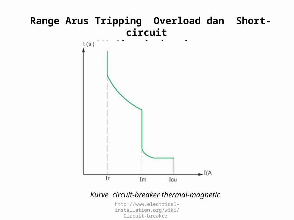
Range Arus Tripping Overload dan Short-circuit LV Circuit-breaker
Kurve circuit-breaker thermal-magnetic

Range Arus Tripping Overload dan Short-circuit LV Circuit-breaker
Ir : Overload (thermal or long-delay) relay trip-current setting. Im: Short-circuit (magnetic or short-delay) relay trip-current setting
Ii : Short-circuit instantaneous relay trip-current setting. Icu: Breaking capacity
Kurve circuit-breaker thermal-magnetic electronic
http://www.electrical-installation.org/wiki/Circuit-breaker

http://www.electrical-installation.org/wiki/Circuit-breaker

http://www.electrical-installation.org/wiki/Circuit-breaker
Rated Short-circuit Breaking Capacity (Icu or Icn)
Rating short-circuit current-breaking dari CB adalah nilai tertinggi (prospective) ketika CB masih mampu breaking tanpa terjadi kerusakan pada CB.
Nilai standard nya adalah nilai rms dari komponen AC arus gangguan, sehingga nilai komponen DC transient (yang biasanya terjadi pada kasus terburuk hubung singkat ) diasumsikan nol untuk perhitungan nilai berbasis standard ini.
Nilai Icu untuk industrial CB, dan Nilai Icn untuk domestic CBs diberikan dalam kA rms.
Icu (rated ultimate s.c. breaking capacity) and Ics (rated service s.c. breaking capacity) are defined in IEC 60947-2 together with a table relating Ics with Icu for different categories of utilization A (instantaneous tripping) and B (time-delayed tripping)

http://www.electrical-installation.org/wiki/Circuit-breaker
a) Pengujian Rating s.c. breaking capacity dari CB adalah terkait standard yang meliputi ;
b) Urutan operasi (operating sequences), membuka dan menutup pada kejadian hubung singkat.
c) Pergeseran fasa arus dan tegangan. Ketika arus sefasa dengan tegangan sumber (cosφ sirkit = 1), pemadaman arus (interruption of the current) lebih mudah dari faktor daya yang lain.
d) Breaking dari arus dengan faktor daya rendah adalah lebih sulit dicapai;
e) Faktor daya nol ( zero power-factor ) secara teoritis adalah kasus yang paling parah. Pada praktisnya kebanyakan arus gangguan pada sistem tenaga adalah dengan faktor daya lagging.
f) Secara umum lebih besar level arus gangguan (at a given voltage), lebih rendah faktor daya dari loop arus gangguan, contoh pada generator atau transformer.
Pengujian Rating S.C. Breaking Capacity

http://www.electrical-installation.org/wiki/Circuit-breaker
IEC 60947-2 : relates standardized values of cos ϕ to industrial circuit-breakers according to their rated Icu.
Icu related to power factor (cosφ) of fault-current circuit (IEC 60947-2)
Following an open - time delay - close/open sequence to test the Icu capacity of a CB, further tests are made to ensure that: - The dielectric withstand capability - The disconnection (isolation) performance and - The correct operation of the overload protection have not been impaired by the test.

http://www.electrical-installation.org/wiki/Circuit-breaker
Adalah nilai tegangan ketika dilakukan uji tegangan dielektrik ( biasanya lebih besar dari 2 Ui) dari jarak rambat (creepage distances) acuan.Nilai maximum dari rating tegangan operational harus tidak melampaui rated insulation voltage, artinya Ue ≤ Ui.
Rated Insulation Voltage (Ui)

http://www.electrical-installation.org/wiki/Circuit-breaker
This characteristic expresses, in kV peak (of a prescribed form and polarity) the value of voltage which the equipment is capable of withstanding without failure, under test conditions.
Generally, for industrial circuit-breakers, Uimp = 8 kV and for domestic types, Uimp = 6 kV.
Rated Impulse-withstand Voltage (Uimp)

http://www.electrical-installation.org/wiki/Circuit-breaker
Category (A or B)
Rated Short-time Withstand Current (Icw)
Those of category A, for which there is no deliberate delay in the operation of the “instantaneous” short-circuit magnetic tripping device
Category A circuit-breaker

http://www.electrical-installation.org/wiki/Circuit-breaker
Category (A or B)
Rated Short-time Withstand Current (Icw)1) Category B dipilih untuk melakukan diskriminasi
dengan circuit-breaker yang lain berbasis waktu, dimungkinkan untuk menunda tripping dari CB, ketika level arus gangguan lebih rendah dari short-time withstand current rating (Icw) pada CB.
2) Umumnya dipilih untuk large open-type circuit-breakers , dan untuk type heavy-duty moulded-case tertentu.
3) Icw is the maximum current that the B category CB can withstand, thermally and electrodynamically, without sustaining damage, for a period of time given by the manufacturer.
Icw adalah arus maximum dari CB category B dapat menahan secara termal dan elektrodinamik tanpa berdampak kerusakan untuk suatu periode waktu yang ditunjukan oleh pabrikan.
Category B circuit-breaker

http://www.electrical-installation.org/wiki/Circuit-breaker
Icm is the highest instantaneous value of current that the circuit-breaker can establish at rated voltage in specified conditions. In AC systems this instantaneous peak value is related to Icu (i.e. to the rated breaking current) by the factor k, which depends on the power factor (cos ϕ) of the short-circuit current loop
Rated Making Capacity (Icm)
Relation between rated breaking capacity Icu and rated making capacity Icm at different power-factor values of short-circuit current, as standardized in IEC 60947-2

http://www.electrical-installation.org/wiki/Circuit-breaker
Contoh:
A Masterpact NW08H2 circuit-breaker has a rated breaking capacity Icu of 100
kA. The peak value of its rated making capacity Icm will be 100 x 2.2 = 220 kA.

http://www.electrical-installation.org/wiki/Circuit-breaker
Rated service short-circuit breaking capacity (Ics)
Pada rancangan instalasi yang baik, circuit-breaker tidak akan beroperasi pada maximum breaking current Icu. Karena alasan itu diperkenalkan karakteristik Ics. IEC 60947-2 Icu (25, 50, 75, 100%)
Rated breaking capacity (Icu) atau (Icn) adalah arus gangguan tertinggi yang dapat diinterupsi tanpa circuit-breaker mengalami kerusakan. Probabilitas arus ini adalah sangatlah rendah, dan dalam kondisi normal arus gangguan lebih kecil daripada rated breaking capacity (Icu) .

http://www.electrical-installation.org/wiki/Circuit-breaker
Rated Service Short-circuit Breaking Capacity (Ics)
Di sisi lain arus tinggi (probabilitas rendah) harus diinterupsi dengan tepat, sehingga CB segera untuk reclosure, setelah terjadi pemulihan gangguan.
The standard test sequence is as follows:
O - CO - CO(1) (at Ics)
Tests carried out following this sequence are intended to verify that the CB is in a good state and available for normal serviceFor domestic CBs, Ics = k Icn. The factor k values are given in IEC 60898 table XIV.In Europe it is the industrial practice to use a k factor of 100% so that Ics = Icu.
(1) O represents an opening operation.CO represents a closing operation followed by an opening operation.

http://www.electrical-installation.org/wiki/Circuit-breaker
Kemampuan membatasi arus gangguan dari CB, dapat menjadi lebih efektif atau kurang efektif, dalam proses mencegah lintasan arus gangguan prospective mencapai maximum, karena hanya dalam jumlah arus yang terbatas yang memungkin-kan mengalir .
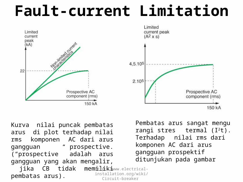
Fault-current Limitation
Prospective and actual current
http://www.electrical-installation.org/wiki/Circuit-breaker
Kurva nilai puncak pembatas arus di plot terhadap nilai rms komponen AC dari arus gangguan prospective. (“prospective” adalah arus gangguan yang akan mengalir, jika CB tidak memiliki pembatas arus).
Fault-current Limitation
Pembatas arus sangat mengurangi stres termal (I2t). Terhadap nilai rms dari komponen AC dari arus gangguan prospektif ditunjukan pada gambar

http://www.electrical-installation.org/wiki/Circuit-breaker
The use of current-limiting CBs affords numerous advantages:Better conservation of installation networks: current-limiting CBs strongly attenuate all harmful effects associated with short-circuit currentsReduction of thermal effects: Conductors (and therefore insulation) heating is significantly reduced, so that the life of cables is correspondingly increasedReduction of mechanical effects: forces due to electromagnetic repulsion are lower, with less risk of deformation and possible rupture, excessive burning of contacts, etc.Reduction of electromagnetic-interference effects: - Less influence on measuring instruments and associated circuits, telecommunication systems, etc.These circuit-breakers therefore contribute towards an improved exploitation of:Cables and wiringPrefabricated cable-trunking systemsSwitchgear, thereby reducing the ageing of the installation
Keuntungan Pembatas Arus

http://www.electrical-installation.org/wiki/Circuit-breaker
Keuntungan Penggunaan Pembatas Arus ( Current Limiter ) pada CB :
a. Sangat melemahkan efek berbahaya yang terkait dengan arus hubung pendek.
b. Mengurangi pengaruh efek termal: pemanasan konduktor berkurang secara signifikan, sehingga umur pakai kabel meningkat.
c. Mengurangi pengaruh efek mekanik: karena kekuatan repulsi elektromagnetik yang lebih rendah, yang mengurangi risiko; deformasi dan kemungkinan pecah , kontak terbakar, dll.
d. Mengurangi pengaruh interferensi – elektromagnetik sehingga melindungi ; instrumen ukur dan sirkit terkait, sistem telekomunikasi, dll. Sehingga circuit-breaker berkontribusi terhadap perbaikan : Kabel dan wiring, sistem kabel trunking, umur instalasi switchgear.
Keuntungan Pembatas Arus ( Current Limiter )

http://www.electrical-installation.org/wiki/Circuit-breaker
Example
On a system having a prospective shortcircuit current of 150 kA rms, a Compact L circuit-breaker limits the peak current to less than 10% of the calculated prospective peak value, and the thermal effects to less than 1% of those calculated.
Cascading of the several levels of distribution in an installation, downstream of a limiting CB, will also result in important savings.The technique of cascading allows, in fact, substantial savings on switchgear (lower performance permissible downstream of the limiting CB(s)) enclosures, and design studies, of up to 20% (overall).
Discriminative protection schemes and cascading are compatible, in the Compact NSX range, up to the full short-circuit breaking capacity of the switchgear.

http://www.electrical-installation.org/wiki/Circuit-breaker
The rated current of a circuit-breaker is defined for operation at a given ambient temperature, in general:a. 30 °C for domestic-type CBsb. 40 °C for industrial-type CBsPerformance of these CBs in a different ambient temperature depends mainly on the technology of their tripping units.
Memilih Arus Rating (Rated Current) ( Terms Of Ambient Temperature )

http://www.electrical-installation.org/wiki/Circuit-breaker
Uncompensated Thermal Magnetic Tripping UnitsCircuit-breakers with uncompensated thermal tripping units have a trip current level that depends on the surrounding temperature
Jika CB dipasang pada enclosure, atau di lokasi yang panas ( misalnya pada ruangan boiler), arus trip overload pada CB akan berkurang sensitifitas nya.Bila suhu di mana CB terletak melampaui temperatur referensi, maka akan terjadi "derated".

http://www.electrical-installation.org/wiki/Circuit-breaker
CB modular tipe kecil yang dipasang berjajar, pada panel logam kecil ditutup. Faktor derated adalah 0,8.

http://www.electrical-installation.org/wiki/Circuit-breaker
Examples of tables for the determination of derating/uprating factors to apply to CBs with uncompensated thermal tripping units, according to temperature

http://www.electrical-installation.org/wiki/Circuit-breaker
ExampleWhat rating (In) should be selected for a C60 N?Protecting a circuit, the maximum load current of which is estimated to be 34 AInstalled side-by-side with other CBs in a closed distribution boxIn an ambient temperature of 50 °CA C60N circuit-breaker rated at 40 A would be derated to 35.6 A in ambient air at 50 °C (see Fig. H41). To allow for mutual heating in the enclosed space, however, the 0.8 factor noted above must be employed, so that, 35.6 x 0.8 = 28.5 A, which is not suitable for the 34 A load.A 50 A circuit-breaker would therefore be selected, giving a (derated) current rating of 44 x 0.8 = 35.2 A.

http://www.electrical-installation.org/wiki/Circuit-breaker
Electronic tripping units are highly stable in changing temperature levels
An important advantage with electronic tripping units is their stable performance in changing temperature conditions. However, the switchgear itself often imposes operational limits in elevated temperatures, so that manufacturers generally provide an operating chart relating the maximum values of permissible trip-current levels to the ambient temperature.
Electronic Trip Units
Moreover, electronic trip units can provide information that can be used for a better management of the electrical distribution, including energy efficiency and power quality.

http://www.electrical-installation.org/wiki/Circuit-breaker
Derating of Masterpact NW20 circuit-breaker, according to the temperature

http://www.electrical-installation.org/wiki/Circuit-breaker
Selection of An Instantaneous, Or Short-time-delay, Tripping Threshold

http://www.electrical-installation.org/wiki/Circuit-breaker
Selection of a circuit-breaker according to the short-circuit breaking capacity requirements
The installation of a LV circuit-breaker requires that its short-circuit breaking capacity (or that of the CB together with an associated device) be equal to or exceeds the calculated prospective short-circuit current at its point of installation
The installation of a circuit-breaker in a LV installation must fulfil one of the two following conditions:Either have a rated short-circuit breaking capacity Icu (or Icn) which is equal to or exceeds the prospective short-circuit current calculated for its point of installation, orIf this is not the case, be associated with another device which is located upstream, and which has the required short-circuit breaking capacityIn the second case, the characteristics of the two devices must be co-ordinated such that the energy permitted to pass through the upstream device must not exceed that which the downstream device and all associated cables, wires and other components can withstand, without being damaged in any way. This technique is profitably employed in:Associations of fuses and circuit-breakersAssociations of current-limiting circuit-breakers and standard circuit-breakers.The technique is known as “cascading”

http://www.electrical-installation.org/wiki/Circuit-breaker
The Selection of Main and Principal Circuit BreakersThe circuit-breaker at the output of the smallest transformer must have a short-circuit capacity adequate for a fault current which is higher than that through any of the other transformer LV circuit-breakers
A single transformerIf the transformer is located in a consumer’s substation, certain national standards require a LV circuit-breaker in which the open contacts are clearly visible such as Compact NSX withdrawable circuit-breaker.
What type of circuit-breaker is suitable for the main circuit-breaker of an installation supplied through a 250 kVA MV/LV (400 V) 3-phase transformer in a consumer’s substation?In transformer = 360 AIsc (3-phase) = 8.9 kAA Compact NSX400N with an adjustable tripping-unit range of 160 A - 400 A and a short-circuit breaking capacity (Icu) of 50 kA would be a suitable choice for this duty.

http://www.electrical-installation.org/wiki/Circuit-breaker
A Compact NSX400N with an adjustable tripping-unit range of 160 A - 400 A and a short-circuit breaking capacity (Icu) of 50 kA would be a suitable choice for this duty.

http://www.electrical-installation.org/wiki/Circuit-breaker
The circuit-breakers CBP outgoing from the LV distribution board must each be capable of breaking the total fault current from all transformers connected to the busbars, viz: Isc1 + Isc2 + Isc3The circuit-breakers CBM, each controlling the output of a transformer, must be capable of dealing with a maximum short-circuit current of (for example) Isc2 + Isc3 only, for a short-circuit located on the upstream side of CBM1.From these considerations, it will be seen that the circuit-breaker of the smallest transformer will be subjected to the highest level of fault current in these circumstances, while the circuit-breaker of the largest transformer will pass the lowest level of short-circuit currentThe ratings of CBMs must be chosen according to the kVA ratings of the associated transformers
Several Transformers in Parallel

http://www.electrical-installation.org/wiki/Circuit-breaker
Note: The essential conditions for the successful operation of 3-phase transformers in parallel may be summarized as follows:1. the phase shift of the voltages, primary to secondary, must be the same in all units to be paralleled.2. the open-circuit voltage ratios, primary to secondary, must be the same in all units.3. the short-circuit impedance voltage (Zsc%) must be the same for all units. For example, a 750 kVA transformer with a Zsc = 6% will share the load correctly with a 1,000 kVA transformer having a Zsc of 6%, i.e. the transformers will be loaded automatically in proportion to their kVA ratings. For transformers having a ratio of kVA ratings exceeding 2, parallel operation is not recommended.

http://www.electrical-installation.org/wiki/Circuit-breaker
Figure H46 indicates, for the most usual arrangement (2 or 3 transformers of equal kVA ratings) the maximum short-circuit currents to which main and principal CBs (CBM and CBP respectively, in Figure H45) are subjected. It is based on the following hypotheses:The short-circuit 3-phase power on the MV side of the transformer is 500 MVAThe transformers are standard 20/0.4 kV distribution-type units rated as listedThe cables from each transformer to its LV circuit-breaker comprise 5 metres of single core conductorsBetween each incoming-circuit CBM and each outgoing-circuit CBP there is 1 metre of busbarThe switchgear is installed in a floormounted enclosed switchboard, in an ambient-air temperature of 30 °CMoreover, this table shows selected circuit-breakers of M-G manufacture recommended for main and principal circuit-breakers in each case.

http://www.electrical-installation.org/wiki/Circuit-breaker
Example (see Fig. H47 )
Circuit-breaker selection for CBM duty:For a 800 kVA transformer In = 1.126 A; Icu (minimum) = 38 kA (from Figure H46), the CBM indicated in the table is a Compact NS1250N (Icu = 50 kA)Circuit-breaker selection for CBP duty:The s.c. breaking capacity (Icu) required for these circuit-breakers is given in the Figure H46 as 56 kA.A recommended choice for the three outgoing circuits 1, 2 and 3 would be current-limiting circuit-breakers types NSX400 L, NSX250 L and NSX100 L. The Icu rating in each case = 150 kA.
These circuit-breakers provide the advantages of: - Absolute discrimination with the upstream (CBM) breakers - Exploitation of the “cascading” technique, with its associated savings for all downstream components
http://www.electrical-installation.org/wiki/Circuit-breaker
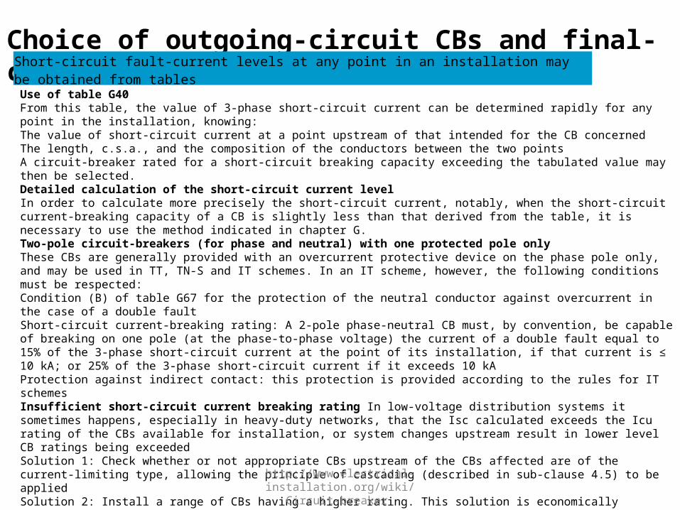
Choice of outgoing-circuit CBs and final-circuit CBsShort-circuit fault-current levels at any point in an installation may be obtained from tables
Use of table G40From this table, the value of 3-phase short-circuit current can be determined rapidly for any point in the installation, knowing:The value of short-circuit current at a point upstream of that intended for the CB concernedThe length, c.s.a., and the composition of the conductors between the two pointsA circuit-breaker rated for a short-circuit breaking capacity exceeding the tabulated value may then be selected.Detailed calculation of the short-circuit current levelIn order to calculate more precisely the short-circuit current, notably, when the short-circuit current-breaking capacity of a CB is slightly less than that derived from the table, it is necessary to use the method indicated in chapter G.Two-pole circuit-breakers (for phase and neutral) with one protected pole onlyThese CBs are generally provided with an overcurrent protective device on the phase pole only, and may be used in TT, TN-S and IT schemes. In an IT scheme, however, the following conditions must be respected:Condition (B) of table G67 for the protection of the neutral conductor against overcurrent in the case of a double faultShort-circuit current-breaking rating: A 2-pole phase-neutral CB must, by convention, be capable of breaking on one pole (at the phase-to-phase voltage) the current of a double fault equal to 15% of the 3-phase short-circuit current at the point of its installation, if that current is ≤ 10 kA; or 25% of the 3-phase short-circuit current if it exceeds 10 kAProtection against indirect contact: this protection is provided according to the rules for IT schemesInsufficient short-circuit current breaking rating In low-voltage distribution systems it sometimes happens, especially in heavy-duty networks, that the Isc calculated exceeds the Icu rating of the CBs available for installation, or system changes upstream result in lower level CB ratings being exceededSolution 1: Check whether or not appropriate CBs upstream of the CBs affected are of the current-limiting type, allowing the principle of cascading (described in sub-clause 4.5) to be appliedSolution 2: Install a range of CBs having a higher rating. This solution is economically interesting only where one or two CBs are affectedSolution 3: Associate current-limiting fuses (gG or aM) with the CBs concerned, on the upstream side. This arrangement must, however, respect the following rules: - The fuse rating must be appropriate - No fuse in the neutral conductor, except in certain IT installations where a double fault produces a current in the neutral which exceeds the short-circuit breaking rating of the CB. In this case, the blowing of the neutral fuse must cause the CB to trip on all phases.

http://www.electrical-installation.org/wiki/Circuit-breaker
Coordination between circuit-breakersThe technique of “cascading” uses the properties of current-limiting circuit-breakers to permit the installation of all downstream switchgear, cables and other circuit components of significantly lower performance than would otherwise be necessary, thereby simplifying and reducing the cost of an installation
Cascading (or Back-up protection)
Definition of the cascading technique By limiting the peak value of short-circuit current passing through it, a current-limiting CB permits the use, in all circuits downstream of its location, of switchgear and circuit components having much lower short-circuit breaking capacities, and thermal and electromechanical withstand capabilities than would otherwise be necessary. Reduced physical size and lower performance requirements lead to substantial economy and to the simplification of installation work. It may be noted that, while a current-limiting circuit-breaker has the effect on downstream circuits of (apparently) increasing the source impedance during short-circuit conditions, it has no such effect in any other condition; for example, during the starting of a large motor (where a low source impedance is highly desirable). The range of Compact NSX current-limiting circuit-breakers with powerful limiting performances is particularly interesting.

http://www.electrical-installation.org/wiki/Circuit-breaker
Conditions of implementationThe technique of “cascading” uses the properties of current-limiting circuit-breakers to permit the installation of all downstream switchgear, cables and other circuit components of significantly lower performance than would otherwise be necessary, thereby simplifying and reducing the cost of an installation
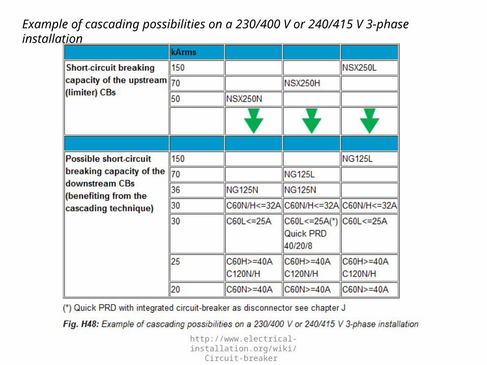
Most national standards admit the cascading technique, on condition that the amount of energy “let through” by the limiting CB is less than the energy all downstream CBs and components are able to withstand without damage.In practice this can only be verified for CBs by tests performed in a laboratory. Such tests are carried out by manufacturers who provide the information in the form of tables, so that users can confidently design a cascading scheme based on the combination of recommended circuit-breaker types. As an example, Figure H48 indicates the cascading possibilities of circuit-breaker types C60, DT40N, C120 and NG125 when installed downstream of current-limiting CBs Compact NSX 250 N, H or L for a 230/400 V or 240/415 V 3-phase installation.
http://www.electrical-installation.org/wiki/Circuit-breaker
Example of cascading possibilities on a 230/400 V or 240/415 V 3-phase installation

http://www.electrical-installation.org/wiki/Circuit-breaker
The current limitation benefits all downstream circuits that are controlled by the current-limiting CB concerned.The principle is not restrictive, i.e. current-limiting CBs can be installed at any point in an installation where the downstream circuits would otherwise be inadequately rated.The result is:Simplified short-circuit current calculationsSimplification, i.e. a wider choice of downstream switchgear and appliancesThe use of lighter-duty switchgear and appliances, with consequently lower costEconomy of space requirements, since light-duty equipment have generally a smaller volume
Advantages of Cascading

http://www.electrical-installation.org/wiki/Circuit-breaker
Discrimination is achieved by automatic protective devices if a fault condition, occurring at any point in the installation, is cleared by the protective device located immediately upstream of the fault, while all other protective devices remain unaffected (see Fig. H49).
Total and partial discrimination

http://www.electrical-installation.org/wiki/Circuit-breaker
Discrimination between circuit-breakers A and B is total if the maximum value of short-circuit-current on circuit B (Isc B) does not exceed the short-circuit trip setting of circuit-breaker A (Im A). For this condition, B only will trip (see Fig. H50).
Total discrimination between CBs A and B

http://www.electrical-installation.org/wiki/Circuit-breaker
Discrimination is partial if the maximum possible short-circuit current on circuit B exceeds the short-circuit trip-current setting of circuit-breaker A. For this maximum condition, both A and B will trip
Partial discrimination between CBs A and B

http://www.electrical-installation.org/wiki/Circuit-breaker
Protection Against Overload : Discrimination Based On Current Levels (see Fig. H52a)
This method is realized by setting successive tripping thresholds at stepped levels, from downstream relays (lower settings) towards the source (higher settings). Discrimination is total or partial, depending on particular conditions, as noted above
As a rule of thumb, discrimination is achieved when:
IrA/IrB > 2:

http://www.electrical-installation.org/wiki/Circuit-breaker
Protection against low level short-circuit currents : discrimination based on stepped time delays (see Fig. H52b)This method is implemented by adjusting the time-delayed tripping units, such that downstream relays have the shortest operating times, with progressively longer delays towards the source.In the two-level arrangement shown, upstream circuit-breaker A is delayed sufficiently to ensure total discrimination with B (for example: Masterpact with electronic trip unit).

http://www.electrical-installation.org/wiki/Circuit-breaker
Discrimination based on a combination of the two previous methods (see Fig. H52c)A time-delay added to a current level scheme can improve the overall discrimination performance.The upstream CB has two high-speed magnetic tripping thresholds:Im A: delayed magnetic trip or short-delay electronic tripIi: instantaneous stripDiscrimination is total if Isc B < Ii (instantaneous).

http://www.electrical-installation.org/wiki/Circuit-breaker
Protection against high level short-circuit currents: discrimination based on arc-energy levelsThis technology implemented in the Compact NSX range (current limiting circuit- breaker) is extremely effective for achievement of total discrimination.Principle: When a very high level short-circuit current is detected by the two circuits- breaker A and B, their contacts open simultaneously. As a result, the current is highly limited.The very high arc-energy at level B induces the tripping of circuit-breaker BThen, the arc-energy is limited at level A and is not sufficient to induce the tripping of AAs a rule of thumb, the discrimination between Compact NSX is total if the size ratio between A and B is greater than 2.5.

http://www.electrical-installation.org/wiki/Circuit-breaker
Current-level discrimination
This technique is directly linked to the staging of the Long Time (LT) tripping curves of two serial-connected circuit-breakers.
The discrimination limit ls is:Is = Isd2 if the thresholds lsd1 and lsd2 are too close or merge,Is = Isd1 if the thresholds lsd1 and lsd2 are sufficiently far apart.As a rule, current discrimination is achieved when:Ir1 / Ir2 < 2,Isd1 / Isd2 > 2.The discrimination limit is:Is = Isd1.

http://www.electrical-installation.org/wiki/Circuit-breaker
Discrimination qualityDiscrimination is total if Is > Isc(D2), i.e. Isd1 > Isc(D2). This normally implies:a relatively low level Isc(D2),a large difference between the ratings of circuit-breakers D1 and D2.Current discrimination is normally used in final distribution.
Time discrimination
Discrimination based on time-delayed tripping uses CBs referred to as “selective” (in some countries).Implementation of these CBs is relatively simple and consists in delaying the instant of tripping of the several series-connected circuit-breakers in a stepped time sequence

http://www.electrical-installation.org/wiki/Circuit-breaker
This is the extension of current discrimination and is obtained by staging over time of the tripping curves. This technique consists of giving a time delay of t to the Short Time (ST) tripping of D1.

http://www.electrical-installation.org/wiki/Circuit-breaker
Discrimination quality
on final and/or intermediate feedersA category circuit-breakers can be used with time-delayed tripping of the upstream circuit-breaker. This allows extension of current discrimination up to the instantaneous threshold li1 of the upstream circuit-breaker: Is = li1.If Isc(D2) is not too high - case of a final feeder - total discrimination can be obtained.on the incomers and feeders of the MSBAt this level, as continuity of supply takes priority, the installation characteristics allow use of B category circuit-breakers designed for time-delayed tripping. These circuit-breakers have a high thermal withstand (Icw ≥ 50% Icn for t = 1s): Is = Icw1.Even for high lsc(D2), time discrimination normally provides total discrimination: Icw1 > Icc(D2).

http://www.electrical-installation.org/wiki/Circuit-breaker
Note: Use of B category circuit-breakers means that the installation must withstand high electrodynamic and thermal stresses.Consequently, these circuit-breakers have a high instantaneous threshold li that can be adjusted and disabled in order to protect the busbars if necessary.Practical example of discrimination at several levels with Schneider Electric circuit-breakers (with electronic trip units)"Masterpact NT is totally selective with any moulded-case Compact NSX circuit breaker, i.e., the downstream circuit-breaker will trip for any short-circuit value up to its breaking capacity. Further, all Compact NSX CBs are totally selective, as long as the ration between sizes is greater than 1.6 and the ratio between ratings is greater than 2.5. The same rules apply for the total selectivity with the miniature circuit-breakers Multi9 further downstream (see Fig. H55).

http://www.electrical-installation.org/wiki/Circuit-breaker

http://www.electrical-installation.org/wiki/Circuit-breaker
Cascading between 2 devices is normally achieved by using the tripping of the upstream circuit-breaker A to help the downstream circuit-breaker B to break the current. The discrimination limit Is is consequently equal to the ultimate breaking current Icu B of circuit-breaker B acting alone, as cascading requires the tripping of both devices.The energy discrimination technology implemented in Compact NSX circuit-breakers allows to improve the discrimination limit to a value higher than the ultimate breaking current Icu B of the downstream circuit-breaker. The principle is as follows:The downstream limiting circuit-breaker B sees a very high short-circuit current. The tripping is very fast (<1 ms) and then, the current is limitedThe upstream circuit-breaker A sees a limited short-circuit current compared to its breaking capability, but this current induces a repulsion of the contacts. As a result, the arcing voltage increases the current limitation. However, the arc energy is not high enough to induce the tripping of the circuit-breaker. So, the circuit-breaker A helps the circuit-breaker B to trip, without tripping itself. The discrimination limit can be higher than Icu B and the discrimination becomes total with a reduced cost of the device
Energy Discrimination With Current Limitation

http://www.electrical-installation.org/wiki/Circuit-breaker
Natural total discriminitation with Compact NSXThe major advantage of the Compact NSX range is to provide a natural total discrimination between two series-connected devices if:The ratio of the two trip-unit current ratings is > 1.6The ratio of rated currents of the two circuit-breakers is > 2.5

http://www.electrical-installation.org/wiki/Circuit-breaker
Logic discrimination or “Zone Sequence Interlocking – ZSI”
Discrimination schemes based on logic techniques are possible, using CBs equipped with electronic tripping units designed for the purpose (Compact, Masterpact) and interconnected with pilot wires
This type of discrimination can be achieved with circuit-breakers equipped with specially designed electronic trip units (Compact, Masterpact): only the Short Time Protection (STP) and Ground Fault Protection (GFP) functions of the controlled devices are managed by Logic Discrimination. In particular, the Instantaneous Protection function - inherent protection function - is not concerned.Settings of controlled circuit-breakerstime delay: there are no rules, but staging (if any)of the time delays of time discrimination must be applied (ΔtD1 ≥ ΔtD2 ≥ ΔtD3),thresholds: there are no threshold rules to be applied, but natural staging of the protection device ratings must be complied with (IcrD1 ≥ IcrD2 ≥ IcrD3).Note: This technique ensures discrimination even with circuit-breakers of similar ratings.[edit]PrinciplesActivation of the Logic Discrimination function is via transmission of information on the pilot wire:ZSI input: - low level (no downstream faults): the Protection function is on standby with a reduced time delay (y 0,1 s), - high level (presence of downstream faults): the relevant Protection function moves to the time delay status set on the device.ZSI output: - low level: the trip unit detects no faults and sends no orders, - high level: the trip unit detects a fault and sends an order.

http://www.electrical-installation.org/wiki/Circuit-breaker
OperationA pilot wire connects in cascading form the protection devices of an installation (see Fig. H56). When a fault occurs, each circuit-breaker upstream of the fault (detecting a fault) sends an order (high level output) and moves the upstream circuit-breaker to its natural time delay (high level input). The circuitbreaker placed just above the fault does not receive any orders (low level input) and thus trips almost instantaneously.

http://www.electrical-installation.org/wiki/Circuit-breaker
Discrimination qualityThis technique enables:easy achievement as standard of discrimination on 3 levels or more,elimination of important stresses on the installation, relating to time-delayed tripping of the protection device, in event of a fault directly on the upstream busbars.All the protection devices are thus virtually instantaneous,easy achievement of downstream discrimination with non-controlled circuit-breakers.

http://www.electrical-installation.org/wiki/Circuit-breaker
Discrimination MV/LV in a consumer’s substationIn general the transformer in a consumer’s substation is protected by MV fuses, suitably rated to match the transformer, in accordance with the principles laid down in IEC 60787 and IEC 60420, by following the advice of the fuse manufacturer.The basic requirement is that a MV fuse will not operate for LV faults occurring downstream of the transformer LV circuit-breaker, so that the tripping characteristic curve of the latter must be to the left of that of the MV fuse pre-arcing curve.This requirement generally fixes the maximum settings for the LV circuit-breaker protection:Maximum short-circuit current-level setting of the magnetic tripping elementMaximum time-delay allowable for the short-circuit current tripping element

http://www.electrical-installation.org/wiki/Circuit-breaker
Example:Short-circuit level at MV terminals of transformer: 250 MVATransformer MV/LV: 1,250 kVA 20/0.4 kVMV fuses: 63 ACabling, transformer - LV circuit-breaker: 10 metres single-core cablesLV circuit-breaker: Compact NSX 2000 set at 1,800 A (Ir)What is the maximum short-circuit trip current setting and its maximum time delay allowable?The curves of Figure H58 show that discrimination is assured if the short-time delay tripping unit of the CB is set at:A level ≤ 6 Ir = 10.8 kAA time-delay setting of step 1 or 2

http://www.electrical-installation.org/wiki/Circuit-breaker
Ultra-rapid Circuit BreakerAs installed power increases, electrical distribution has to shift from a LV design to a HV design. Indeed, a high short-circuit level can be a threat to the installation and make impossible the selection of low voltage equipments (Switchboard and bus bars, circuit breaker…)These situations could be met in the following applications:Bus bars coupling onboard merchant vessels, off shore platform, loop networks (in industry), where the current and energy are important because of the installed power (several transformers or generators in parallel) and HV design not easy.Two solutions could be used:[edit]- Pyrotechnic interruption switching device[edit]- Power circuit breaker based solution
Some power circuit breakers with additionnal feature (based on the Thomson effect technology for instance) provide an ultrarapid opening system on very high short-circuit level. The breaking performance makes it possible to limit theshort-circuit current and prospective energy, and consequently protect the electrical installation against the electrodynamic and thermal effects of short-circuit.

http://www.electrical-installation.org/wiki/Circuit-breaker
Example of ultra rapid power circuit breaker: Masterpact UR

http://www.electrical-installation.org/wiki/Circuit-breaker
Example of limitation offered by Masterpact UR in decoupling bus bars in case of short circuit:
When a short-circuit occurs downstream in the installation (A) with no tie breaker, the short-circuit level will be the total sum of all the generated power (illustrated by curve 1).

http://www.electrical-installation.org/wiki/Circuit-breaker
By inserting a tie breaker - Masterpact UR - to separate the sources under fault conditions, the short circuit at (A) will consist in:a limited short circuit coming from generator G1 and G2 interrupted by the Masterpact UR (see curve 2) a non limited short circuit from generators G3 and G4 (see curve 3).

http://www.electrical-installation.org/wiki/Circuit-breaker
The resulting short circuit level is illustrated by curve 4.

http://www.electrical-installation.org/wiki/Circuit-breaker
The consequence of the strong limitation of the short circuit current and the prospective energy allows the design of a LV network instead of a MV design.This also prevents the network from being totally shutdown (black out) in case of short circuit in the main switchboard.
The following table give some example of limitation with MAsterpact UR as a tie breaker between source 1 & 2

http://www.electrical-installation.org/wiki/Circuit-breaker
http://www.electrical-installation.org/wiki/Circuit-breaker