55250 01 gs5_gs501_dz_rca-30
TRANSCRIPT
Page 1 55250-01_97_A
GS501DZ Tech Sheet
55250-01_97_A.pdf 02/05/2009Template used: 40599_97_O.pdf 11/08/2008
BalboaSystem PN 55250-01
System Model # GS5-GS501DZ-RCA-3.0Software Version # 43EPN # 2808
Base PCBA – PN 55251-01PCB GS500Z – PN 22015 Rev B
Base PanelsVL801D (Serial Deluxe) – PN 54121VL802D – PN 54562
http://www.MyPoolSpas.com Wholesale Pool and Spa Parts 920-925-3094
Page 2 55250-01_97_A
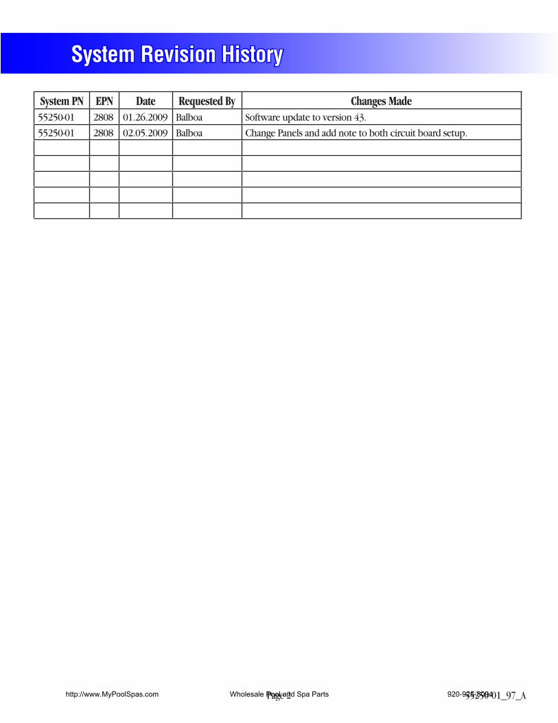
System Revision History
System PN EPN Date Requested By Changes Made55250-01 2808 01.26.2009 Balboa Software update to version 43.
55250-01 2808 02.05.2009 Balboa Change Panels and add note to both circuit board setup.
http://www.MyPoolSpas.com Wholesale Pool and Spa Parts 920-925-3094
Page 3 55250-01_97_A
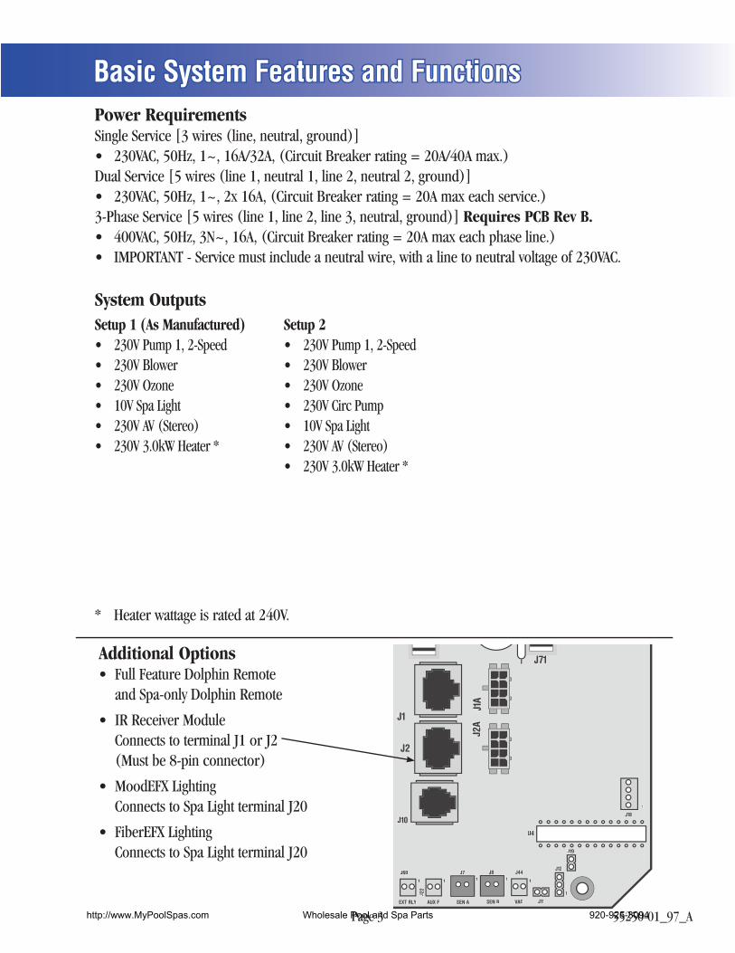
Additional Options
Power Requirements
Requires PCB Rev B.
System Outputs
J1
J2
J10
J71
J1A
J2A
J60 J44
J181
1
1
11 11J7 J8
EXT RLY SEN A VACSEN B
J22
AUX F J11
J12
J19
U4
Basic System Features and Functions
Setup 1 (As Manufactured)
(Stereo)
Setup 2
(Stereo)
http://www.MyPoolSpas.com Wholesale Pool and Spa Parts 920-925-3094
Page 4 55250-01_97_A
Basic System Features and Functions
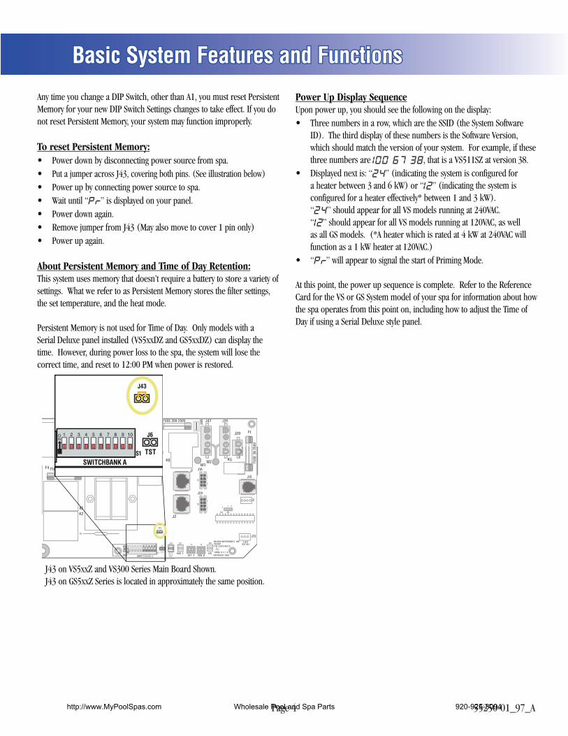
Any time you change a DIP Switch, other than A1, you must reset Persistent Memory for your new DIP Switch Settings changes to take effect. If you do not reset Persistent Memory, your system may function improperly.
To reset Persistent Memory: Power down by disconnecting power source from spa. Put a jumper across J43, covering both pins. (See illustration below) Power up by connecting power source to spa. Wait until “ ” is displayed on your panel. Power down again. Remove jumper from J43 (May also move to cover 1 pin only) Power up again.
About Persistent Memory and Time of Day Retention:This system uses memory that doesn’t require a battery to store a variety of settings. What we refer to as Persistent Memory stores the filter settings, the set temperature, and the heat mode.
Persistent Memory is not used for Time of Day. Only models with a Serial Deluxe panel installed (VS5xxDZ and GS5xxDZ) can display the time. However, during power loss to the spa, the system will lose the correct time, and reset to 12:00 PM when power is restored.
Power Up Display SequenceUpon power up, you should see the following on the display:
Three numbers in a row, which are the SSID (the System Software ID). The third display of these numbers is the Software Version, which should match the version of your system. For example, if these three numbers are , that is a VS511SZ at version 38.
Displayed next is: “ ” (indicating the system is configured for a heater between 3 and 6 kW) or “ ” (indicating the system is configured for a heater effectively* between 1 and 3 kW). “ ” should appear for all VS models running at 240VAC. “ ” should appear for all VS models running at 120VAC, as well as all GS models. (*A heater which is rated at 4 kW at 240VAC will function as a 1 kW heater at 120VAC.)
“ ” will appear to signal the start of Priming Mode.
At this point, the power up sequence is complete. Refer to the Reference Card for the VS or GS System model of your spa for information about how the spa operates from this point on, including how to adjust the Time of Day if using a Serial Deluxe style panel.
GC
GC
GC
GC
CG
T1
SWITC
BALBOA INSTRUMENTS, INC.VS500ZP/N 22972 REV D
MADE IN U.S.ACOPYRIGHT 2005
J7 J8J44J22
U4
FUSE .3A 250V
FUSE 20A 250V
50V
E.GN
D
F4
K6 K1
K8K9
K5
J23 J46
J46
F1
J29J47J50 F7
J17/
26 J20
J1A
J10
J13
J2A
AUX. FSEN. A SEN. B
VACVV
W1
W7
J1
J2
W2W3
GC
W4
K2K3
F2
J12
1 2 3
J43
2-SPDEXT RLY
J18
SWITCHBANK AS1
J6
E.GN
D
TST
J43
J43 on VS5xxZ and VS300 Series Main Board Shown.J43 on GS5xxZ Series is located in approximately the same position.
GC
S
P/N
2296
4_B
MAD
E IN
U.S.
A.VS
100
© 2
006
S1
K3
K5
K4 K1
PUMP
K2
J7 J8
U4
T0.25A 250VF2
J23
GC
OZONEJ29
HEATERAA
J9
J20
SEN. A SEN. B
J1
Balbo
a F4
G C
J26
J58 J57
J50
J50
J13
J13
J12
J12
J90
J90
LINE
NEUTRALNEUTRALWHT AC
BLK AC
W1
J18
SWITCHBANK A
TST RSTJ43J6
J43 on VS100/GS100 Series Main Board Shown.
http://www.MyPoolSpas.com Wholesale Pool and Spa Parts 920-925-3094
Page 5 55250-01_97_A
TB1
HTR2 J101 00HTR1
G N
J50
T1
J1
J2
J10
J57
J58J58
J71 10VA
C10VAC
J46
J255
J266
J72
J90
J288J28
J1A
J2A
J322
J52 J51J F6, T30A 480V
AV
OZONE PUMP 1
OPT. BLWR/PUMP 2
CIRC. PUMP
K1
K3K4
K6
E.GN
D
J47
G N
GN
GN
J29 J23
GN
J17/26
K2
K9
J20
G N
W2
1
2
3
4
W1BalboaBALBOA INSTRUMENTS, INC.GS500ZCOPYRIGHT 2007MADE IN U.S.A.P/N 22015_B
J60 J44
J181
1
1
11 11J7 J8
EXT RLYTST
J6
SEN A VACSEN B
J22
J43
AUX F
J13
J11
J12
J19F2
S1
SWITCHBANK A
K8K5
C9
U4
F3A 250V
F7 F1F10A 250V
F4, T0.2A 250V
bbPbbbbPPPb
F3
Blower
GS50xZ mode
3.0 kWHeater rated @ 240VJ11 must be Jumpered
3.0kW
Spa Light
Audio Visual
Ozone
1-Spd P12-Spd P1
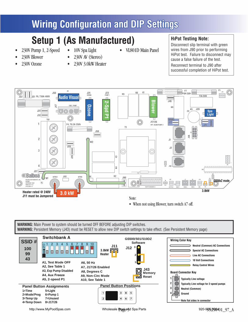
Wiring Configuration and DIP Settings
Setup 1 (As Manufactured)(Stereo)
Note:
A1, Test Mode OFFA2, See Table 1A3, Exp Pump Disabled
A7, J17/26 Disabled
A10, See Table 1A9, Non-Circ Mode
A5, 2-speed P1
Panel Button Assignments1=Time2=Mode/Prog3=Temp Up4=Temp Down
5=Light6=Pump 17=Unused8=Unused
Panel Button Positions
1
2
3
4
8
6
5
7
1009943
SSID #J11
3.0kWHeater
J12
1
2
3
GS500/501/510DZSoftware
MemoryReset
J43A8, Degrees CA7, J17/26 Enabled
8=J17/26
A6, 50 Hz
Neutral (Common) AC Connections
Special AC Connections
Line AC Connections
10 Volt Connections
Relay Control Wires
Wiring Color Key
Typically Line voltage
Typically Line voltage for 2-speed pumps
Neutral (Common)
Ground
Note flat sides in connector
Board Connector Key
1
2
3
4
WARNING: Main Power to system should be turned OFF BEFORE adjusting DIP switches.WARNING: Persistent Memory (J43) must be RESET to allow new DIP switch settings to take effect. (See Persistent Memory page)
HIPot Testing Note:Disconnect slip terminal with green wires from J90 prior to performing HiPot test. Failure to disconnect may cause a false failure of the test.Reconnect terminal to J90 after successful completion of HiPot test.
http://www.MyPoolSpas.com Wholesale Pool and Spa Parts 920-925-3094
Page 6 55250-01_97_A
TB1
HTR2 J101 00HTR1
G N
J50
T1
J1
J2
J10
J57
J58J58
J71 10VA
C10VAC
J46
J255
J266
J72
J90
J288J28
J1A
J2A
J322
J52 J51J F6, T30A 480V
AV
OZONE PUMP 1
OPT. BLWR/PUMP 2
CIRC. PUMP
K1
K3K4
K6
E.GN
D
J47
G N
GN
GN
J29 J23
GN
J17/26
K2
K9
J20
G N
W2
1
2
3
4
W1BalboaBALBOA INSTRUMENTS, INC.GS500ZCOPYRIGHT 2007MADE IN U.S.A.P/N 22015_B
J60 J44
J181
1
1
11 11J7 J8
EXT RLYTST
J6
SEN A VACSEN B
J22
J43
AUX F
J13
J11
J12
J19F2
S1
SWITCHBANK A
K8K5
C9
U4
F3A 250V
F7 F1F10A 250V
F4, T0.2A 250V
bbPbbbbPPPb
F3
Blower
GS50xZ mode
3.0 kWHeater rated @ 240VJ11 must be Jumpered
3.0kW
Spa Light
Audio Visual
Circ Pump
Ozone
1-Spd P12-Spd P1
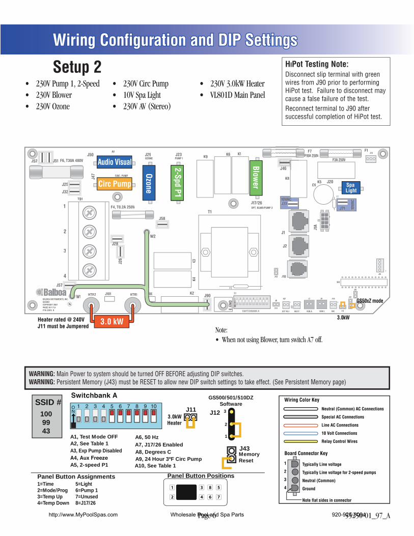
Wiring Configuration and DIP Settings
Setup 2
(Stereo)
A1, Test Mode OFFA2, See Table 1A3, Exp Pump Disabled
A7, J17/26 Disabled
A10, See Table 1A9, Non-Circ Mode
A5, 2-speed P1
Panel Button Assignments1=Time2=Mode/Prog3=Temp Up4=Temp Down
5=Light6=Pump 17=Unused8=Unused
Panel Button Positions
1
2
3
4
8
6
5
7
1009943
SSID #J11
3.0kWHeater
J12
1
2
3
GS500/501/510DZSoftware
MemoryReset
J43A8, Degrees CA7, J17/26 Enabled
8=J17/26
A6, 50 Hz
A9, 24 Hour 3ºF Circ PumpA5, 2-speed P1
Neutral (Common) AC Connections
Special AC Connections
Line AC Connections
10 Volt Connections
Relay Control Wires
Wiring Color Key
Typically Line voltage
Typically Line voltage for 2-speed pumps
Neutral (Common)
Ground
Note flat sides in connector
Board Connector Key
1
2
3
4
WARNING: Main Power to system should be turned OFF BEFORE adjusting DIP switches.WARNING: Persistent Memory (J43) must be RESET to allow new DIP switch settings to take effect. (See Persistent Memory page)
HIPot Testing Note:Disconnect slip terminal with green wires from J90 prior to performing HiPot test. Failure to disconnect may cause a false failure of the test.Reconnect terminal to J90 after successful completion of HiPot test.
Note:
http://www.MyPoolSpas.com Wholesale Pool and Spa Parts 920-925-3094
Page 7 55250-01_97_A
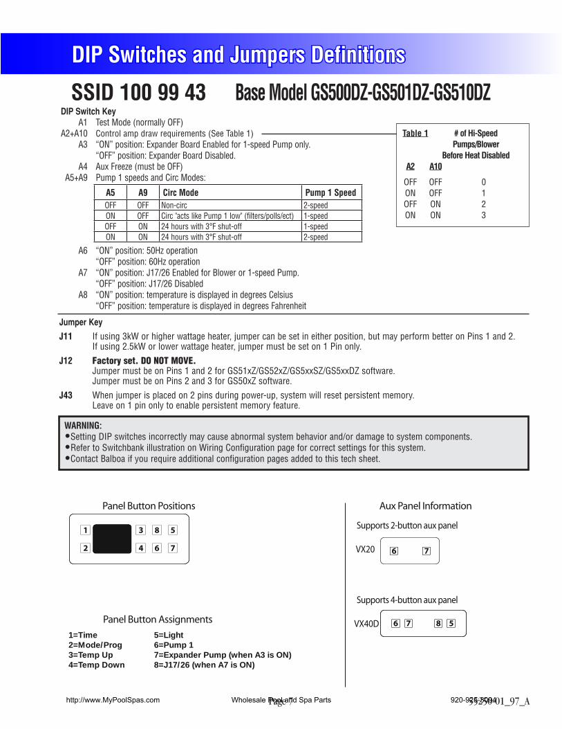
Base Model GS500DZ-GS501DZ-GS510DZ
DIP Switches and Jumpers Definitions
Jumper Key
J11 If using 3kW or higher wattage heater, jumper can be set in either position, but may perform better on Pins 1 and 2. If using 2.5kW or lower wattage heater, jumper must be set on 1 Pin only.
J12 Factory set. DO NOT MOVE. Jumper must be on Pins 1 and 2 for GS51xZ/GS52xZ/GS5xxSZ/GS5xxDZ software. Jumper must be on Pins 2 and 3 for GS50xZ software.
J43 When jumper is placed on 2 pins during power-up, system will reset persistent memory. Leave on 1 pin only to enable persistent memory feature.
SSID 100 99 43
WARNING:Setting DIP switches incorrectly may cause abnormal system behavior and/or damage to system components.Refer to Switchbank illustration on Wiring Configuration page for correct settings for this system.Contact Balboa if you require additional configuration pages added to this tech sheet.
Panel Button Positions Aux Panel Information
Panel Button Assignments
1=Time2=Mode/Prog3=Temp Up4=Temp Down
5=Light6=Pump 17=Expander Pump (when A3 is ON)8=J17/26 (when A7 is ON)
Supports 2-button aux panel
VX20
Supports 4-button aux panel
VX40D
6
6 7 8 5
7
1
2
3
4
8
6
5
7
Table 1 # of Hi-Speed Pumps/Blower Before Heat Disabled A2 A10
OFF OFF 0 ON OFF 1 OFF ON 2 ON ON 3
DIP Switch Key A1 Test Mode (normally OFF) A2+A10 Control amp draw requirements (See Table 1) A3 “ON” position: Expander Board Enabled for 1-speed Pump only. “OFF” position: Expander Board Disabled. A4 Aux Freeze (must be OFF) A5+A9 Pump 1 speeds and Circ Modes:
A5 A9 Circ Mode Pump 1 SpeedOFF OFF Non-circ 2-speedON OFF Circ "acts like Pump 1 low" (filters/polls/ect) 1-speedOFF ON 24 hours with 3°F shut-off 1-speedON ON 24 hours with 3°F shut-off 2-speed
A6 “ON” position: 50Hz operation “OFF” position: 60Hz operation A7 “ON” position: J17/26 Enabled for Blower or 1-speed Pump. “OFF” position: J17/26 Disabled A8 “ON” position: temperature is displayed in degrees Celsius “OFF” position: temperature is displayed in degrees Fahrenheit
http://www.MyPoolSpas.com Wholesale Pool and Spa Parts 920-925-3094
Page 8 55250-01_97_A
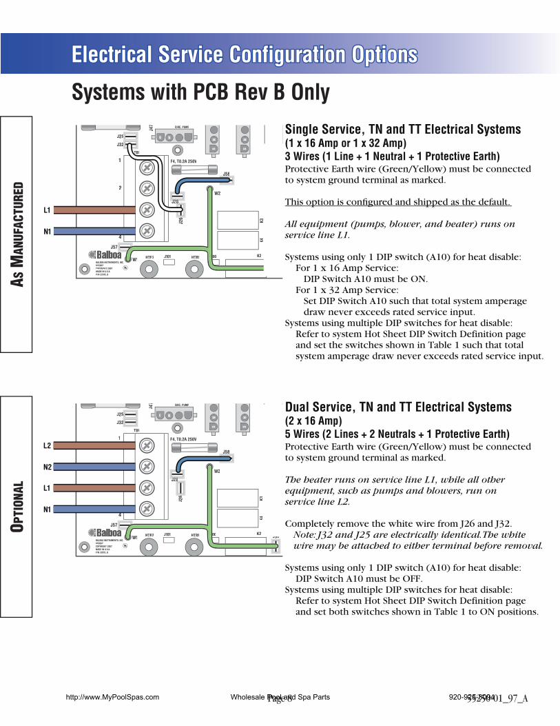
Electrical Service Configuration Options
TB1
HTR2 J101 00HTR1
G N
J50
T1
J1
J2
J10
J57
J58J58
J71 10VA
C10VAC
J46J46
J255
J266
J72
J90
J288J28
J1A
J2A
J322
J52 J51J F6, T30A 480V
AV
OZONE PUMP 1
OPT. BLWR/PUMP 2
CIRC. PUMP
K1
K3K4
K6
E.GN
D
J47
G N
GN
GN
J29 J23
GN
J17/26
K2
K9
J20
G N
W2
1
2
3
4
W1BalboaBALBOA INSTRUMENTS, INC.GS500ZCOPYRIGHT 2007MADE IN U.S.A.P/N 22015_B
J60 J44
J181
1
1
11 11J7 J8
EXT RLYTST
J6
SEN A VACSEN B
J22
J43
AUX F
J13
J11
J12
J19F2
S1
SWITCHBANK A
K8K5
C9
U4
F3A 250V
F7 F1F10A 250V
F4, T0.2A 250V
PbbPP
F3
L1
N1
L2
N2
TB1
HTR2 J101 00HTR1
G N
J50
T1
J1
J2
J10
J57
J58J58
J71 10VA
C10VAC
J46J46
J255
J266
J72
J90
J288J28
J1A
J2A
J322
J52 J51J F6, T30A 480V
AV
OZONE PUMP 1
OPT. BLWR/PUMP 2
CIRC. PUMP
K1
K3K4
K6
E.GN
D
J47
G N
GN
GN
J29 J23
GN
J17/26
K2
K9
J20
G N
W2
1
2
3
4
W1BalboaBALBOA INSTRUMENTS, INC.GS500ZCOPYRIGHT 2007MADE IN U.S.A.P/N 22015_B
J60 J44
J181
1
1
11 11J7 J8
EXT RLYTST
J6
SEN A VACSEN B
J22
J43
AUX F
J13
J11
J12
J19F2
S1
SWITCHBANK A
K8K5
C9
U4
F3A 250V
F7 F1F10A 250V
F4, T0.2A 250V
PbbPP
F3
L1
N1
Single Service, TN and TT Electrical Systems(1 x 16 Amp or 1 x 32 Amp) 3 Wires (1 Line + 1 Neutral + 1 Protective Earth)Protective Earth wire (Green/Yellow) must be connectedto system ground terminal as marked.
This option is configured and shipped as the default.
All equipment (pumps, blower, and heater) runs onservice line L1.
Systems using only 1 DIP switch (A10) for heat disable: For 1 x 16 Amp Service: DIP Switch A10 must be ON. For 1 x 32 Amp Service: Set DIP Switch A10 such that total system amperage draw never exceeds rated service input.Systems using multiple DIP switches for heat disable: Refer to system Hot Sheet DIP Switch Definition page and set the switches shown in Table 1 such that total system amperage draw never exceeds rated service input.
Dual Service, TN and TT Electrical Systems(2 x 16 Amp)5 Wires (2 Lines + 2 Neutrals + 1 Protective Earth)Protective Earth wire (Green/Yellow) must be connectedto system ground terminal as marked.
The heater runs on service line L1, while all otherequipment, such as pumps and blowers, run on service line L2.
Completely remove the white wire from J26 and J32. Note: J32 and J25 are electrically identical. The white wire may be attached to either terminal before removal.
Systems using only 1 DIP switch (A10) for heat disable: DIP Switch A10 must be OFF.Systems using multiple DIP switches for heat disable: Refer to system Hot Sheet DIP Switch Definition page and set both switches shown in Table 1 to ON positions.
AS M
ANUF
ACTU
RED
OPTI
ONAL
Systems with PCB Rev B Only
http://www.MyPoolSpas.com Wholesale Pool and Spa Parts 920-925-3094
Page 9 55250-01_97_A
Electrical Service Configuration Options
TB1
HTR2 J101 00HTR1
G N
J50
T1
J1
J2
J10
J57
J58J58
J71 10VA
C10VAC
J46J46
J255
J266
J72
J90
J288J28
J1A
J2A
J322
J52 J51J F6, T30A 480V
AV
OZONE PUMP 1
OPT. BLWR/PUMP 2
CIRC. PUMP
K1
K3K4
K6
E.GN
D
J47
G N
GN
GN
J29 J23
GN
J17/26
K2
K9
J20
G N
W2
1
2
3
4
W1BalboaBALBOA INSTRUMENTS, INC.GS500ZCOPYRIGHT 2007MADE IN U.S.A.P/N 22015_B
J60 J44
J181
1
1
11 11J7 J8
EXT RLYTST
J6
SEN A VACSEN B
J22
J43
AUX F
J13
J11
J12
J19F2
S1
SWITCHBANK A
K8K5
C9
U4
F3A 250V
F7 F1F10A 250V
F4, T0.2A 250V
PbbPP
F3
L1
N
L3
L2
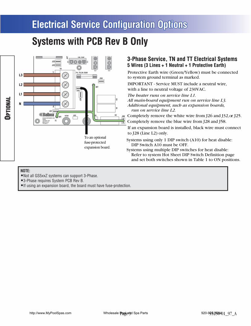
3-Phase Service, TN and TT Electrical Systems5 Wires (3 Lines + 1 Neutral + 1 Protective Earth)
Completely remove the white wire from J26 and J32, or J25.
To an optionalfuse-protectedexpansion board.
Completely remove the blue wire from J28 and J58.
IMPORTANT - Service MUST include a neutral wire,with a line to neutral voltage of 230VAC.
Protective Earth wire (Green/Yellow) must be connectedto system ground terminal as marked.
The heater runs on service line L1.All main-board equipment run on service line L3.Addtional equipment, such as expansion boards, run on service line L2.
If an expansion board is installed, black wire must connectto J28 (Line L2) only.
Systems using only 1 DIP switch (A10) for heat disable: DIP Switch A10 must be OFF.Systems using multiple DIP switches for heat disable: Refer to system Hot Sheet DIP Switch Definition page and set both switches shown in Table 1 to ON positions.
OPTI
ONAL
Systems with PCB Rev B Only
NOTE:Not all GS5xxZ systems can support 3-Phase.3-Phase requires System PCB Rev B.If using an expansion board, the board must have fuse-protection.
http://www.MyPoolSpas.com Wholesale Pool and Spa Parts 920-925-3094
Page 10 55250-01_97_A
Electrical Service Configuration Options
TB1
HTR2 J101 00HTR1
G N
J50
T1
J1
J2
J10
J57
J58J58
J71 10VA
C10VAC
J46J46
J255
J266
J72
J90
J288J28
J1A
J2A
J322
J52 J51J F6, T30A 480V
AV
OZONE PUMP 1
OPT. BLWR/PUMP 2
CIRC. PUMP
K1
K3K4
K6
E.GN
D
J47
G N
GN
GN
J29 J23
GN
J17/26
K2
K9
J20
G N
W2
1
2
3
4
W1BalboaBALBOA INSTRUMENTS, INC.GS500ZCOPYRIGHT 2007MADE IN U.S.A.P/N 22015_B
J60 J44
J181
1
1
11 11J7 J8
EXT RLYTST
J6
SEN A VACSEN B
J22
J43
AUX F
J13
J11
J12
J19F2
S1
SWITCHBANK A
K8K5
C9
U4
F3A 250V
F7 F1F10A 250V
F4, T0.2A 250V
PbbPPPP
F3
TB1
HTR2 J101 00HTR1
G N
J50
T1
J1
J2
J10
J57
J58J58
J71 10VA
C10VAC
J46J46
J255
J266
J72
J90
J288J28
J1A
J2A
J322
J52 J51J F6, T30A 480V
AV
OZONE PUMP 1
OPT. BLWR/PUMP 2
CIRC. PUMP
K1
K3K4
K6
E.GN
D
J47
G N
GN
GN
J29 J23
GN
J17/26
K2
K9
J20
G N
W2
1
2
3
4
W1BalboaBALBOA INSTRUMENTS, INC.GS500ZCOPYRIGHT 2007MADE IN U.S.A.P/N 22015_B
J60 J44
J181
1
1
11 11J7 J8
EXT RLYTST
J6
SEN A VACSEN B
J22
J43
AUX F
J13
J11
J12
J19F2
S1
SWITCHBANK A
K8K5
C9
U4
F3A 250V
F7 F1F10A 250V
F4, T0.2A 250V
PbbPP
F3
L1
L2
L1
L2
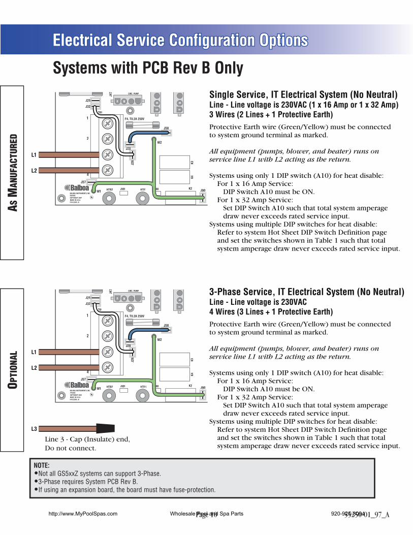
Single Service, IT Electrical System (No Neutral)Line - Line voltage is 230VAC (1 x 16 Amp or 1 x 32 Amp) 3 Wires (2 Lines + 1 Protective Earth) Protective Earth wire (Green/Yellow) must be connectedto system ground terminal as marked.
All equipment (pumps, blower, and heater) runs onservice line L1 with L2 acting as the return.
Systems using only 1 DIP switch (A10) for heat disable: For 1 x 16 Amp Service: DIP Switch A10 must be ON. For 1 x 32 Amp Service: Set DIP Switch A10 such that total system amperage draw never exceeds rated service input.Systems using multiple DIP switches for heat disable: Refer to system Hot Sheet DIP Switch Definition page and set the switches shown in Table 1 such that total system amperage draw never exceeds rated service input.
3-Phase Service, IT Electrical System (No Neutral)Line - Line voltage is 230VAC4 Wires (3 Lines + 1 Protective Earth) Protective Earth wire (Green/Yellow) must be connectedto system ground terminal as marked.
All equipment (pumps, blower, and heater) runs onservice line L1 with L2 acting as the return.
Systems using only 1 DIP switch (A10) for heat disable: For 1 x 16 Amp Service: DIP Switch A10 must be ON. For 1 x 32 Amp Service: Set DIP Switch A10 such that total system amperage draw never exceeds rated service input.Systems using multiple DIP switches for heat disable: Refer to system Hot Sheet DIP Switch Definition page and set the switches shown in Table 1 such that total system amperage draw never exceeds rated service input.
L3
Line 3 - Cap (Insulate) end,Do not connect.
AS M
ANUF
ACTU
RED
OPTI
ONAL
Systems with PCB Rev B Only
NOTE:Not all GS5xxZ systems can support 3-Phase.3-Phase requires System PCB Rev B.If using an expansion board, the board must have fuse-protection.
http://www.MyPoolSpas.com Wholesale Pool and Spa Parts 920-925-3094
Page 11 55250-01_97_A
Ozone Connections
TB1
G RBW
J50
J57
J58
J25
J90
J28
J32
J52 J51 F6, T30A 480V
AV
OZONE PUMP 1
CIRC. PUMP
J47
G RBW
GR
BW
J29 J23
W2
1
2
F4, T0.2A 250V
Audio Visual
Circ Pump
2-Spd P1Empty
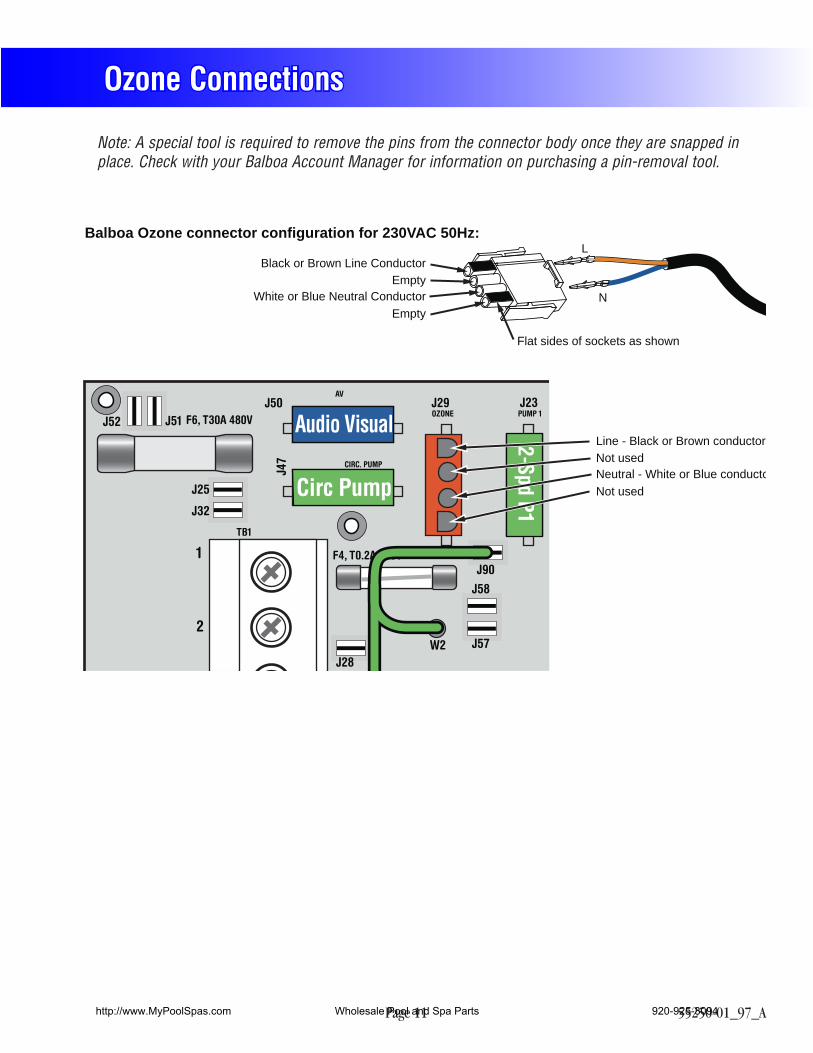
Black or Brown Line Conductor
Balboa Ozone connector configuration for 230VAC 50Hz: L
NEmpty
White or Blue Neutral Conductor
Flat sides of sockets as shown
Not usedLine - Black or Brown conductor
Not usedNeutral - White or Blue conducto
Note: A special tool is required to remove the pins from the connector body once they are snapped in place. Check with your Balboa Account Manager for information on purchasing a pin-removal tool.
http://www.MyPoolSpas.com Wholesale Pool and Spa Parts 920-925-3094
Page 12 55250-01_97_A
Serial Deluxe Panel Configurations
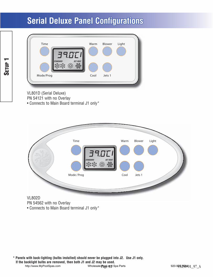
Time Warm Blower Light
CoolMode/Prog Jets 1
VL801D (Serial Deluxe)PN 54121 with no Overlay Connects to Main Board terminal J1 only*
SETU
P 1
BlowerTime Warm
Mode / Prog Cool Jets 1
Light
VL802DPN 54562 with no Overlay Connects to Main Board terminal J1 only*
* Panels with back-lighting (bulbs installed) should never be plugged into J2. Use J1 only. If the backlight bulbs are removed, then both J1 and J2 may be used.
http://www.MyPoolSpas.com Wholesale Pool and Spa Parts 920-925-3094