56f8300 hybrid controller contents used in control … chip with high-speed can transceiver 56f8300...
TRANSCRIPT
© Freescale Semiconductor, Inc., 2004. All rights reserved.
Freescale SemiconductorApplication Note
AN1999Rev. 0, 11/2004
56F8300 Hybrid Controller Used in Control of Electro-Mechanical BrakeThis application outlines the basics of EMB design based on actuator control of a Permanent Magnet Synchronous Motor with a 56F8300 device
Peter Balazovic
Note: The PC master software referenced in this document isalso known as Free Master software.
1. Introduction This application note describes the electro-mechanical braking(EMB) system and the design basics of its control based onFreescales hybrid 56F8300 controller family of devices.
Electro-mechanical braking systems (see [9], References), alsoreferred to as brake by-wire, replace conventional hydraulicbraking systems with a completely dry electrical componentsystem. This occurs by replacing conventional actuators withelectric motor-driven units. This move to electronic controleliminates many of the manufacturing, maintenance, andenvironmental concerns associated with hydraulic systems.
As in electro-hydraulic braking (EHB), EMB is designed toimprove connectivity with other vehicle systems, thus enablingsimpler integration of higher-level functions, such as tractioncontrol and vehicle stability control. This integration may varyfrom embedding the function within the EMB system, as withABS, to interfacing to these additional systems viacommunication links.
Another advantage of both EHB and EMB systems is theelimination of the large vacuum booster found in conventionalsystems. Along with reducing the dilemma of working with anincreasingly tighter space in the engine bay, this elimination
CONTENTS
1. Introduction ...........................................1
2. Freescale Hybrid Controllers and Automotive ICs ...............................2
2.1 56F8300 Hybrid Controller.................22.2 Intelligent High-Current Single-
Silicon Switch......................................42.3 System-Basis Chip with High-Speed
CAN Transceiver.................................52.4 3-Phase Power MOSFET
Pre-driver.............................................6
3. Braking Systems Overview ..................73.1 Electro-Hydraulic Brakes....................73.2 Hybrid Braking ...................................73.3 Electro-Mechanical Brake...................8
4. Elements of an Electronic Braking System ...........................................10
4.1 Electric Motor Actuator ....................114.2 Electronic Control Module ...............124.3 Sensors ..............................................16
5. EMB controller ...................................195.1 Actuator control ................................195.2 EMB actuation ..................................305.3 Air Gap Adjustment of Brake Pads...315.4 Communication.................................31
6. Freescale Solution for EMB System ...326.1 Single Motor Controller Board .........336.2 Voltage Sensing ................................376.3 Motor Phase Current Sensing ...........376.4 Position and Speed Sensing ..............386.5 Software Implementation..................396.6 Actuator Control Algorithms ............416.7 Application State Diagram................42
7. References ...........................................45
Freescale Hybrid Controllers and Automotive ICs
56F8300 Hybrid Controller Used in Control of Electro-Mechanical Brake, Rev. 0
2 Freescale Semiconductor Preliminary
helps simplify production of right- and left-hand drive vehicle variants. An increase in flexibility for theplacement of components is also provided by EMB systems, compared to those of EHB, with the totalelimination of the hydraulic system.
The assumed EMB complex control requires a dedicated high-performance embedded controller. FreescaleSemiconductors provides dedicated motor control devices based on a 56800E core, which combines DSPpower and parallelism with MCU-like programming simplicity. It is targeted for demanding automotiveapplications like EMB systems. The 56F8300 family includes a number of devices with differnet peripheraland memory sets.
2. Freescale Hybrid Controllers and Automotive ICsFreescale products serve as the foundation for many automotive applications which are ideally suited for therugged automotive enviroment. Continuing Freescales legacy of best-in-class automotive MCUs, FreescaleSemiconductor provides a full family of 0.25µ, 16-bit products based on the powerful 56800E CPU core. Thehigh-performance Flash series of 56F8300 hybrid controllers combines the 56800E hybrid core with Flashmemory, motor control peripherals, and built-in safety features, targeted specifically at automotiveapplications to provide 60 MIPS of performance over the full -40°C to 125°C temperature range. For moreinsight, please see [10] and [11], References.
2.1 56F8300 Hybrid ControllerThe 56F8300 devices are members of the 16-bit 56800E core-based controller family. Each devicesprocessing power, combining the functionality of a microcontroller with a flexible set of peripherals, creates anextremely cost-effective solution on a single chip. Because of its low cost, configuration flexibility, andcompact program code, a 56F8300 device is well-suited for many actuator applications in the automotiveindustry.
The 56800E core is based on a Harvard-style architecture consisting of three execution units operating inparallel, allowing as many as six operations per instruction cycle. The MCU-style programming model andoptimized instruction set allow straightforward generation of efficient, compact 16-bit control code. Theinstruction set is also highly efficient for C/C++ compilers, enabling rapid development of optimized controlapplications.
A typical member of the 56F8300 series provides the following peripheral blocks:
Pulse Width Modulator unit, each with six PWM outputs, three current sense inputs, and fault inputs, fault-tolerant design with deadtime insertion; supports both center- and edge-aligned modes
12-bit Analog-to-Digital Convertor (ADC), supporting two simultaneous conversions with dual 4-pin multiplexed inputs; ADC can be synchronized by PWM modules
Quadrature decoder, dedicated to the quadrature encoder signals with a maximum counting resolution of 4x input signal
Dedicated general-purpose Quad Timers containing four identical counter/timer groups CAN 2.0 A/B module with 2-pin ports used to transmit and receive Serial Communication Interface (SCI) allowing asynchronous serial communications with peripheral
devices and other controllers Serial Peripheral Interface (SPI), with configurable 4-pin port (or four additional GPIO lines) Computer Operating Properly (COP)/watchdog timer Dedicated external interrupt pins

56F8300 Hybrid Controller
56F8300 Hybrid Controller Used in Control of Electro-Mechanical Brake, Rev. 0
Freescale Semiconductor 3Preliminary
General purpose I/O (GPIO) pins, able to multiplex GPIO pins with other peripherals External reset pin for hardware reset JTAG/On-Chip Emulation (OnCE) for unobtrusive, processor speed-independent debugging Software-programmable, Phase Lock Loop-based frequency synthesizer for the core clock
The Analog-to-Digital Converter (ADC) consists of two separate and complete ADCs, each with its ownsample and hold circuits. A common digital control module configures and controls the functioning of bothADCs. ADC features include:
12-bit resolution Maximum ADC clock frequency is 5MHz with a 200ns period Sampling rate up to 1.66 million samples per second Single conversion time of 8.5 ADC clock cycles (8.5 x 200ns = 1.7µs) Additional conversion time of 6 ADC clock cycles (6 x 200ns = 1.2µs) Eight conversions in 26.5 ADC clock cycles (26.5 x 200ns = 5.3µs) using Simultaneous mode ADC conversions can be synchronized by both the PWM and the TMR Simultaneous or sequential sampling with additional text Ability to simultaneously sample and hold two inputs Ability to sequentially scan and store up to eight measurements Internally multiplex to select two of eight inputs Power savings modes allow the automatic shutdown/startup of all or part of the ADC Built-in calibration using on-chip input voltage network Optional interrupts at the end of a scan, if an out-of-range limit is exceeded (either high or low), or at
zero crossing Optional sample correction by subtracting a pre-programmed offset value Signed or unsigned result Single-ended or differential inputs for all input pins with support for an arbitrary mix of input types
The Pulse Width Modulation Unit (PWM) incorporates a PWM generator, enabling the generation of controlsignals for the motor power stage. The module has the following features:
Six PWM signals, which may be used: Independently In complementary pairs In a mix of independent and complementary pairs
Features of complementary channel operation Dead time insertion Separate top and bottom pulse width correction via current status inputs or software Asymmetric PWM output within the center-align operation Separate top and bottom polarity control
Edge- or center-aligned PWM signals 15 bits of resolution Half-cycle reload capability

Freescale Hybrid Controllers and Automotive ICs
56F8300 Hybrid Controller Used in Control of Electro-Mechanical Brake, Rev. 0
4 Freescale Semiconductor Preliminary
Integral reload rates from 1 to 16 Individual software-controlled PWM output Programmable fault protection Polarity control 10/12 mA current source/sink capability on PWM pins Write-protected registers
The powerful timing module called the Quad Timer (QT) contains four identical counter/timer groups, andeach 16-bit counter/timer group features:
Ability to count up and down Counters will cascade Count modulo can be programmed For external clocks, the maximum count rate equals the peripheral clock/2 For internal clocks, the maximum count rate equals the peripheral clock Will count once or repeatedly Counters can be preloaded Counters can share available input pins Each counter has a separate prescaler for Each counter has capture and compare capability
2.2 Intelligent High-Current Single-Silicon SwitchThe 33982 is a self-protected silicon 2.0mΩ high-side switch used to replace electro-mechanical relays, fuses,and discrete devices in power management applications. The 33982 is designed for harsh environments, andincludes self-recovery features. The device is suitable for loads with high in-rush current, as well as motors andall types of resistive and inductive loads.
Programming, control, and diagnostics are implemented via the Serial Peripheral Interface (SPI). A dedicatedparallel input is available for alternate and Pulse Width Modulation (PWM) control of the output. SPIprogrammable fault-trip thresholds allow the device to be adjusted for optimal performance in the application.
Single 2.0mW maximum high-side switch with parallel input or SPI control 6.0V to 27.0V operating voltage with standby currents < 5.0µA An external voltage input pin supplies power to the SPI circuit; if VDD is lost, an internal supply
provides power to a portion of the logic, ensuring the devices limited SPI control of:

System-Basis Chip with High-Speed CAN Transceiver
56F8300 Hybrid Controller Used in Control of Electro-Mechanical Brake, Rev. 0
Freescale Semiconductor 5Preliminary
Overcurrent limit Overcurrent fault blanking time Output-off open load detection Output on/off control Watchdog time-out Slew rates Fault status reporting
SPI status reporting of: Overcurrent Open and shorted loads Overtemperature Undervoltage and overvoltage shutdown Fail-safe pin status Program status
Enhanced 16V reverse-polarity protection of the power supply
2.3 System-Basis Chip with High-Speed CAN TransceiverThe system-basis chip is a dedicated monolithic integrated circuit combining various functions frequently usedby automotive ECM units, and provides different voltage level regulators, high voltage inputs, communicationphysical interface, etc. This chip incorporates:
V1: Low-drop voltage regulator, current limitation, overtemperature detection, monitoring and reset function, and a total current capability of 200mA
V2: Tracking function of VDD1 regulator;control circuitry for an external bipolar ballast transistor, for high flexibility in the choice of peripheral voltage and current supply
Four operational modes: Normal Stand-by Stop Sleep
Low stand-by current consumption in stop and sleep modes High speed 1MBaud CAN physical interface Four external high voltage wake-up inputs, associated with HS1 Vbat switch 150mA output current capability for HS1 Vbat switch, allowing the driving of external switches,
pull-up resistors or relays Vsup failure detection Nominal DC operating voltage from 5.5V to 27V; extended range down to 4.5V 40V maximum transient voltage Programmable software time-out and window watchdog Safe mode with separate outputs for Watchdog time out and Reset

Freescale Hybrid Controllers and Automotive ICs
56F8300 Hybrid Controller Used in Control of Electro-Mechanical Brake, Rev. 0
6 Freescale Semiconductor Preliminary
Wake-up capabilities (four wake-up inputs, programmable cyclic sense, forced wake-up, CAN interface, SPI, and stop mode overcurrent)
Interface with MCU through the SPI
2.4 3-Phase Power MOSFET Pre-driverThe 3-Phase MOSFET pre-driver is an FET pre-driver for 3-phase motor control and similar applications. TheIntegrated Circuit (IC) uses Freescales SMARTMOS technology. and contains three high-side FETpre-drivers and three low-side pre-drivers. Three bootstrap capacitors provide gate charge to the high-sideFETs. The IC interfaces to a 5V or 3V MCU via six direct input control signals and an SPI port for deviceset-up. It is parametrically specified over a 6V to 58V supply range and over a temperature range from -40°Cto +125°C.
42V battery capable Designed to operate from 6V to 58V 1.5A gate drive capability with protection Protection against reverse charge injection from Cgd and Cgs of FETs Includes a simple DC/DC converter for optional reduction of power dissipation Includes a simple charge pump to support full FET drive at low battery voltages Full static capability with an internal charge pump for continuous FET drive Crossover current protection programmable via SPI port Simultaneous output capability enabled via safe SPI command 3.3V-compatible Amplifier for ground current sensing Desaturation detection

Hybrid Braking
56F8300 Hybrid Controller Used in Control of Electro-Mechanical Brake, Rev. 0
Freescale Semiconductor 7Preliminary
3. Braking Systems OverviewThe need for better fuel economy, simplified system assembly, more environmentally friendly systems, ease ofvehicle maneuverability, and improved safety systems has resulted in new types of braking systems.
The centerpiece of the current braking systems is a hydraulic assembly under the hood of the vehicle thatbrings together the electronic control unit, wheel pressure modulators, pressure reservoir, and electric pump.The interaction of mechanics and electronics is key to the success of the braking system. The microcomputer,software, sensors, valves, and electric pump work together to form the basis of the system.
3.1 Electro-Hydraulic BrakesCompared to the operation of conventional braking systems, by depressing the brake pedal with theElectro-Hydraulic Braking System (EHB), the appropriate command is transmitted electronically to theelectronic controller of the hydraulic unit. This determines the optimum braking pressure and actuates thebrake calipers hydraulically (see Figure 3-1).
Figure 3-1. Electro-Hydraulic Braking System
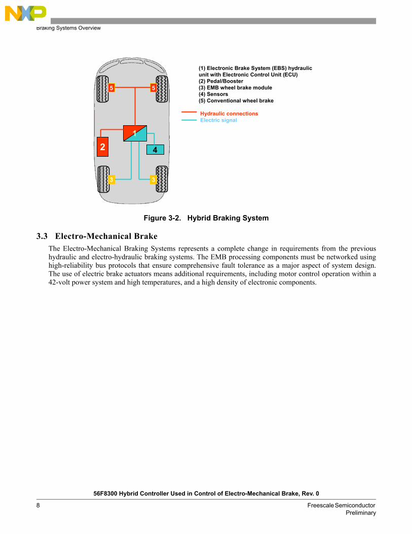
3.2 Hybrid BrakingThe Hybrid Braking System is the solution approach for vehicles without a fully dimensioned on-boardnetwork for dry Electro-Mechanical Brakes (EMB) on all four wheels. There can be integrated electricalparking brake functionality at the rear wheels, eliminating the need for long hydraulic lines and hand-brakingcables leading toward the rear axle.
Since EMB wheel brake modules with integrated electrical parking brake function are already installed at therear wheels, there is no longer any need for long hydraulic lines and hand-braking cables leading toward therear axle. The front axle is operated hydraulically, as with conventional braking systems. This results in atwo-circuit system with two hydraulic wheel brakes on the front axle, and two electro-mechanical wheel brakemodules at the rear axle.
2
1 3
(1) EHB electronic actuator unit with pedal(2) EHB hydraulic unit (3) Sensors
Hydraulic connectionsElectric signalHydraulic Fail Safe2
1 3
2
1 3
(1) EHB electronic actuator unit with pedal(2) EHB hydraulic unit (3) Sensors
Hydraulic connectionsElectric signalHydraulic Fail Safe
Braking Systems Overview
56F8300 Hybrid Controller Used in Control of Electro-Mechanical Brake, Rev. 0
8 Freescale Semiconductor Preliminary
Figure 3-2. Hybrid Braking System
3.3 Electro-Mechanical BrakeThe Electro-Mechanical Braking Systems represents a complete change in requirements from the previoushydraulic and electro-hydraulic braking systems. The EMB processing components must be networked usinghigh-reliability bus protocols that ensure comprehensive fault tolerance as a major aspect of system design.The use of electric brake actuators means additional requirements, including motor control operation within a42-volt power system and high temperatures, and a high density of electronic components.
4
3
5
3
1
5
2 4
3
5
3
1
5
2
(1) Electronic Brake System (EBS) hydraulic unit with Electronic Control Unit (ECU)(2) Pedal/Booster(3) EMB wheel brake module(4) Sensors(5) Conventional wheel brake
Hydraulic connectionsElectric signal

Electro-Mechanical Brake
56F8300 Hybrid Controller Used in Control of Electro-Mechanical Brake, Rev. 0
Freescale Semiconductor 9Preliminary
Figure 3-3. Electro-Mechanical Braking System
The EMB involves in pure brake-by-wire technology, which dispenses with brake fluids and hydraulic linesentirely. The braking force is generated directly at each wheel by high-performance electric motors, controlledby an ECU, and executed by signals from an electronic pedal module. The EMB includes all brake and stabilityfunctions, such as the Anti-lock Braking System (ABS), Electronic Brake Distribution (EBD), TractionControl System (TCS), Electronic Stability Program (ESP), Brake Assist (BA), and Adaptive Cruise Control(ACC). It is virtually noiseless, even in ABS mode.
Advantages of the EMB:
Shorter stopping distances and optimized stability More comfort and safety due to adjustable pedals No pedal vibration in ABS mode Virtually silent Environmentally friendly with no brake fluid Improved crash worthiness Saves space and uses fewer parts Simple assembly Capable of realizing all the required braking and stability functions, such as ABS, EBD, TCS, ESP,
BA, ACC, etc. Can easily be networked with future traffic management systems Additional functions, such as an electric parking brake, can easily be integrated
2
1
4
(1) EMB battery(2) EMB pedal unit with ECU(3) EMB wheel brake module(4) Sensors
Electric signal
3
3
3
3
2
1
4
(1) EMB battery(2) EMB pedal unit with ECU(3) EMB wheel brake module(4) Sensors
Electric signal
3
3
3
3
Elements of an Electronic Braking System
56F8300 Hybrid Controller Used in Control of Electro-Mechanical Brake, Rev. 0
10 Freescale Semiconductor Preliminary
In addition to supporting existing communication standards, such as CAN, EMB systems require theimplementation of deterministic, time-triggered communications, such as those available with FlexRay, toassist in providing the required system fault tolerance. The EMB nodes do not need to be individuallyfault-tolerant, but they help to provide a fail-safe operation, and rely on a high level of fault detection by theelectronic components.
These system requirements must be met using high-end components at very competitive prices, to replace theestablished, cost-effective technology while maintaining strict adherence to the automotive qualification.Delivering the large current required to stop a full-sized SUV may cause limited adoption at first, so the firstimplementation will be on small car platforms.
Freescale has vast experience in developing many of the specific aspects required for the implementation ofEMB systems. Freescale has a strong background in fault-tolerant communications from previous developmentof fail-safe microcontrollers; braking-specific modules such as the wheel speed timer; a dedicated motorcontrol lab, and a software center that develops drivers, tools, and operating systems. Freescale is also a coreteam member in the FlexRay consortium and has been instrumental in the development of this protocol. Withthis solid foundation, Freescale has the knowledge to develop the right solutions in partnership with itscustomers.
4. Elements of an Electronic Braking SystemAn advanced braking system, such as a brake wheel node, generally contains the following elements:
a. Sensorsb. Electric motor actuatorc. Electronic control module (ECM)d. Gear-reduction mechanism
A brake wheel node is illustrated in Figure 4-1.

Electric Motor Actuator
56F8300 Hybrid Controller Used in Control of Electro-Mechanical Brake, Rev. 0
Freescale Semiconductor 11Preliminary
Figure 4-1. Simplified Mechanical Structure of Wheel Brake Node
4.1 Electric Motor ActuatorAll electro-mechanically powered braking systems require an electric motor to convert electrical energy intomechanical energy. Ideally, this could be a rotating electrical machine where the stator is a standard 3-phasestator, like that of an induction motor, and the rotor has mounted permanent magnets (see Figure 4-2). The sizeand weight of the electric motor actuator are extremely important in automotive brake systems, so there is aneed to minimize the package size and actuator weight.
Rotor Disc
Actuator Controller
EMB Actuator
CaliperGear mechanism
Rotor Disc
Actuator Controller
EMB Actuator
CaliperGear mechanism

Elements of an Electronic Braking System
56F8300 Hybrid Controller Used in Control of Electro-Mechanical Brake, Rev. 0
12 Freescale Semiconductor Preliminary
Figure 4-2. Cross Section of a Permanent Magnet AC Machine
Permanent Magnet AC (PMAC) machines provide automotive actuator designers with a unique set of featuresand capabilities. There are two principal classes of permanent magnet AC machines: the first, PermanentMagnet Synchronous Motors, (PMSM) are sinusoidally excited; the second, brushless DC (BLDC) motors, aretrapezoidally excited machines. The primary construction difference is that while stator windings oftrapezoidal PMAC machines are concentrated into a narrow-phase pole, the windings of a sinusoidal machineare typically distributed over multiple slots in order to approximate a sinusoidal distribution. These differencesin construction are also reflected in their corresponding motion characteristics as well, so the first type ofPMAC provides sinusoidal Back-Electromotive Force (back-EMF) generation, and the second type providestrapezoidal back-EMF.
PMSM machines enjoy unique advantages of unsurpassed efficiency and power density characteristics, whichare primarily responsible for their wide appeal. On the other hand, a PMSM machine is synchronous, whichcertainly requires accompanying power electronics, but it also provides the basis for achieving high-qualityactuator control. The torque ripple associated with sinusoidal PMAC PMSM machines is generally less thanthat developed in trapezoidal machines, one reason why sinusoidal motors are preferred in a high-performancemotion control application such as electro-mechanical braking. This application note targets the PMSM only.
4.2 Electronic Control ModuleControl of the electric motor actuator is performed by the Electronic Control Module (ECM). Increasedmicrocontroller processing power, combined with a digital signal processing capability and a flexible set ofperipherals (motor-control related), all provided on single chip, make a 56F8300 device very well suited foruse as the EMB processing core. Such a core allows incorporation of intelligent and advanced braking featuresthat can dramatically enhance driver comfort and safety.
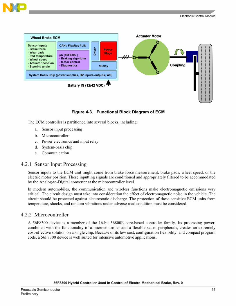
Figure 4-3 illustrates the functional block diagram of the ECM for an electro-mechanical braking system. Themain function of the ECM is to receive the sensor signals from the brake system and vehicle, process thesesignals, and provide appropriate voltage vectors so the motor actuator can obtain the desired torque response.
Stator
Stator winding(in slots)
Shaft
Rotor
Air gap
Permanent magnets
Electronic Control Module
56F8300 Hybrid Controller Used in Control of Electro-Mechanical Brake, Rev. 0
Freescale Semiconductor 13Preliminary
Figure 4-3. Functional Block Diagram of ECM
The ECM controller is partitioned into several blocks, including:
a. Sensor input processingb. Microcontrollerc. Power electronics and input relayd. System-basis chipe. Communication
4.2.1 Sensor Input ProcessingSensor inputs to the ECM unit might come from brake force measurement, brake pads, wheel speed, or theelectric motor position. These inputting signals are conditioned and appropriately filtered to be accommodatedby the Analog-to-Digital converter at the microcontroller level.
In modern automobiles, the communication and wireless functions make electromagnetic emissions verycritical. The circuit design must take into consideration the effect of electromagnetic noise in the vehicle. Thecircuit should be protected against electrostatic discharge. The protection of these sensitive ECM units fromtemperature, shocks, and random vibrations under adverse road condition must be considered.
4.2.2 MicrocontrollerA 56F8300 device is a member of the 16-bit 56800E core-based controller family. Its processing power,combined with the functionality of a microcontroller and a flexible set of peripherals, creates an extremelycost-effective solution on a single chip. Because of its low cost, configuration flexibility, and compact programcode, a 56F8300 device is well suited for intensive automotive applications.
Wheel Brake ECM
µC (56F8300 )- Braking algorithm- Motor control- Diagnostics
CAN / FlexRay / LIN
System Basis Chip (power supplies, HV inputs-outputs, WD)
Driv
er
eRelay
Sensor Inputs- Brake force- Wear pads- Pad temperature- Wheel speed- Actuator position- Steering angle
PowerStage
Actuator Motor
Battery IN (12/42 VDC)
Coupling

Elements of an Electronic Braking System
56F8300 Hybrid Controller Used in Control of Electro-Mechanical Brake, Rev. 0
14 Freescale Semiconductor Preliminary
The 56800E core is based on a Harvard-style architecture consisting of three execution units operating inparallel, allowing as many as six operations per instruction cycle. The MCU-style programming model andoptimized instruction set allow straightforward generation of efficient, compact 16-bit control code. Theinstruction set is also highly efficient for C/C++ compilers, enabling rapid development of optimized controlapplications.
4.2.3 Power Electronics and Input RelayA power inverter is used to apply the desired voltage across the motor phases. The DC-to-AC inverter topologymost widely used today for exciting sinusoidal and trapezoidal PMAC machines is the 3-phase full bridgeinverter. Due to lower automotive voltages, power MOSFETs are commonly used as power electronicswitches.
Advances in power electronic control have made it possible to control electric motors able to providesignificant torque with minimum loss in the power unit. The automotive power MOSFETs can providehundreds of amperes of current, thus making it possible to use them even for electric braking in larger vehicles.Figure 4-4 shows a 3-phase inverter used for a PMSM machine.
A power MOSFET driver device is used to amplify digital PWM signals from the microcontroller. The currentand voltage sensors are used to sense the phase currents and voltage, thus providing feedback for the motorcontrol part of the electro-mechanical brake software. Either a Hall-effect sensor or a shunt resistor is used tosense the electric motor actuator current. The DC-link capacitors are used to filter DCBus voltage. Eithermechanical or electronic relays may be used as disconnecting devices to switch off the electronic system fromthe vehicle battery bus.
Figure 4-4. 3-Phase DC-to-AC Inverter
The electronic relay (eRelay) is a self-protected silicon switch with very low on-state resistance, e.g., 2mΩ. Itis configured as a high-side switch used to replace electro-mechanical relays, fuses, and discrete devices inpower management applications. This silicon device is designed for harsh environments, and it includesself-recovery features. The device is suitable for loads with high in-rush current, as well as motors and all typesof resistive and inductive loads. The different implemented features of this device, such as diagnostics, control,etc. are programable and accessible via Serial Peripheral Interface (SPI).
Driver
U dc_bus
GNDI motor
eRelay+
PWM inputs
DC Linkcapacitors
Driver
U dc_bus
GNDI motor
eRelay+
PWM inputs
DC Linkcapacitors

Electronic Control Module
56F8300 Hybrid Controller Used in Control of Electro-Mechanical Brake, Rev. 0
Freescale Semiconductor 15Preliminary
For maximum device protection, the device has several programmable overcurrent low and high detectionlevels. If the load current level ever reaches the selected overcurrent low detect level, and the overcurrentcondition exceeds the programmed overcurrent time period, the device will latch the output off.
4.2.4 System-Basis ChipThe system-basis chip is a dedicated monolithic integrated circuit, combining various functions frequentlyused by automotive ECM units, providing different voltage level regulators, high voltage inputs,communication physical interfaces, etc.
This device is supplied from an automobile battery line through its input power pin, which is designed forsustaining standard automotive voltage conditions such as load dump. When the supply voltage fallssignificantly, this dedicated system-basis chip is able to detect it and store the information into the SPI registerbit. The device usually incorporates a battery-powered early warning function, which can provide the maskableinterrupt to the microcontroller for evaluation. The device includes voltage regulator capabilities to providedifferent voltage levels for on-board power supplies.
A dedicated device such as the SBC has several modes of operation, including Stand by, Normal, Stop, andSleep Modes. Special modes and configurations are possible for debugging and programming themicrocontrollers Flash memory.
There are several wake-up capabilities available to this device when it is in Sleep or Stop Mode. Whenwake-up has occurred, the wake event is stored in internal device registers, and the voltage regulator isactivated so that the microcontroller is powered back on to bring the ECM unit into fully active operation. Thewake-up lines are dedicated to sensing external event states and, on any change, will wake up themicrocontroller. The device can even wake up from a CAN message if CAN wake-up has been enabled.
Figure 4-5. Generic Block Diagram of a System-Basis Chip
Elements of an Electronic Braking System
56F8300 Hybrid Controller Used in Control of Electro-Mechanical Brake, Rev. 0
16 Freescale Semiconductor Preliminary
4.3 SensorsThere are individual sensors which are definitely needed to operate electro-mechanical braking systems, butthe ECM unit could further benefit from additional new in-car technologies, which allow receipt of informationfrom the engine, transmission, steering angle, and other subsystem information, via in-car communicationlines.
4.3.1 Actuator Position SensingSince the PMSM machines specifically discussed here are synchronous machines, maximum torque can onlybe produced when excitation is precisely synchronized with the instantaneous rotor position. The moststraightforward method of providing the required rotor position information is to mount an absolute angularposition sensor on the PMSM rotor shaft. Alternatively, the accurate position can be derived indirectly fromthe motors voltage and current waveforms using more sophisticated sensorless control algorithms.
Encoder
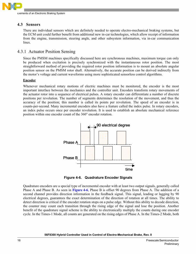
Whenever mechanical rotary motions of electric machines must be monitored, the encoder is the mostimportant interface between the mechanics and the controller unit. Encoders transform rotary movements ofthe actuator rotor into a sequence of electrical pulses. A rotary encoder can differentiate a number of discretepositions per revolution. The number of segments determines the resolution of the movement, and thus theaccuracy of the position; this number is called its points per revolution. The speed of an encoder is incounts-per-second. Many incremental encoders also have a feature called the index pulse. In rotary encoders,an index pulse occurs once per encoder revolution. It is used to establish an absolute mechanical referenceposition within one encoder count of the 360° encoder rotation.
Figure 4-6. Quadrature Encoder Signals
Quadrature encoders are a special type of incremental encoder with at least two output signals, generally calledPhase A and Phase B. As seen in Figure 4-6, Phase B is offset 90 degrees from Phase A. The addition of asecond channel provides direction information in the feedback signal. This signal, leading or lagging by 90electrical degrees, guarantees the exact determination of the direction of rotation at all times. The ability todetect direction is critical if the encoder rotation stops on a pulse edge. Without this ability to decode direction,the counter may count each transition through the rising edge of the signal and lose the position. Anotherbenefit of the quadrature signal scheme is the ability to electronically multiply the counts during one encodercycle. In the Times-1 Mode, all counts are generated on the rising edges of Phase A. In the Times-2 Mode, both
Phase A
Phase B
time
90 electrical degree
Phase A
Phase B
time
90 electrical degree
Sensors
56F8300 Hybrid Controller Used in Control of Electro-Mechanical Brake, Rev. 0
Freescale Semiconductor 17Preliminary
the rising and falling edges of Phase A are used to generate counts. In the Times-4 Mode, the rising and fallingedges of Phase A and Phase B are used to generate counts. This increases the resolution by a factor of four. Forencoders with sine wave output, the channels may be interpolated for very high resolution.
Resolver
Resolver position sensors resemble small motors and are essentially rotary transformers, so the coefficient ofthe coupling between rotor and stator varies with shaft angle. A resolver is based on the concept of encodingthe shaft angle into sine and cosine signals.
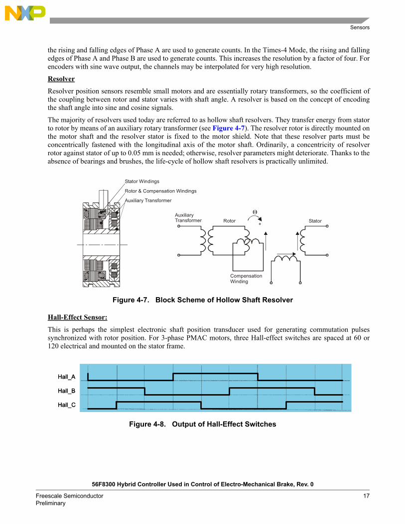
The majority of resolvers used today are referred to as hollow shaft resolvers. They transfer energy from statorto rotor by means of an auxiliary rotary transformer (see Figure 4-7). The resolver rotor is directly mounted onthe motor shaft and the resolver stator is fixed to the motor shield. Note that these resolver parts must beconcentrically fastened with the longitudinal axis of the motor shaft. Ordinarily, a concentricity of resolverrotor against stator of up to 0.05 mm is needed; otherwise, resolver parameters might deteriorate. Thanks to theabsence of bearings and brushes, the life-cycle of hollow shaft resolvers is practically unlimited.
Figure 4-7. Block Scheme of Hollow Shaft Resolver
Hall-Effect Sensor:
This is perhaps the simplest electronic shaft position transducer used for generating commutation pulsessynchronized with rotor position. For 3-phase PMAC motors, three Hall-effect switches are spaced at 60 or120 electrical and mounted on the stator frame.
Figure 4-8. Output of Hall-Effect Switches
StatorRotor
CompensationWinding
AuxiliaryTransformer
Θ
+
Auxiliary Transformer
Stator Windings
Rotor & Compensation Windings
Hall_A
Hall_B
Hall_C
Hall_A
Hall_B
Hall_C

Elements of an Electronic Braking System
56F8300 Hybrid Controller Used in Control of Electro-Mechanical Brake, Rev. 0
18 Freescale Semiconductor Preliminary
Either a separate trigger magnet with the correct pole spacing is mounted on the shaft in close proximity to theHall-effect switches, or the Hall-effect switches can be mounted close to the rotor magnets, where they areenergized by leakage flux at the appropriate rotor position. Another option is to have a sensor arrangementconsisting of a segmented disk (eight segments) and three Hall sensors mounted 120° from each other. Thesegmented disc is mounted on the motor shaft to precisely match the rotor commutation positions. The numberof rotor poles defines the ratio between the mechanical revolution and the electrical period.
Absolute Position Encoder
Digital information on the rotor position can be obtained by special arrangement of a high resolution digitalencoder providing relative position information in combination with a low-resolution commutation sensor.This commutation sensor is attached to the digital encoder and provides synchronization to obtain an absoluterotor position. This sensor allows use of the commutation information for both PMAC machines (brushless DCmotors as well as sinusoidal PMAC). The Hall-effect sensor that generates the logic waves used so commonlyin trapezoidal PMAC machines (BLDC) works on a similar principle.
Figure 4-9. Combination of Telative Encoder and Absolute Commutation Sensor
There are two signals (ENC_A, ENC_B) provided by the digital encoder sensor. These digital outputs createtwo high stream pulse trains, which are intentionally shifted by 90° electrical from each other. Since the digitalsensor provides relative position information only, its necessary to correctly initialize its associated positioncounter, then perform synchronization consecutively. Initialization information is provided by other sensorsignals (HS_A, HS_B, HS_C). The absolute zero position of the rotor is aligned to these sensor signals (HS_A,HS_B, HS_C).
By combining these two approaches in position information generation, and with dedicated peripherals for the56F8300 microcontroller, it is possible to achieve high resolution of the rotor angular position and know theabsolute position.
HS_A
HS_C
HS_B
ENC_A
ENC_B
2/3π
π
HS_A
HS_C
HS_B
ENC_A
ENC_B
2/3π
π
Actuator control
56F8300 Hybrid Controller Used in Control of Electro-Mechanical Brake, Rev. 0
Freescale Semiconductor 19Preliminary
4.3.2 Wheel SpeedIn most cases, there are a number of different speed sensor types available. The selection may be determinedby the familiarity of the system designer with a sensor, though on other hand, the output from one sensor canbe used for several applications (ABS, ASR, EMB, etc.), and the individual requirements of each applicationmay eventually determine the sensor type to be used.
In wheel speed measurement, speed sensors are attached to all four wheels so that the slip differential betweenthe wheels can be measured. This information can be distributed into applications such as ABS, ASR, fourwheel steering, and electro-mechanical braking.
Due to their simplicity and proven reliability, variable reluctance wheel speed sensors are typically used inABS applications. In conjuction with the exciter rings, this type of sensor produces a sinusoidal output that isdirectly proportional in frequency and amplitude to the angular velocity of the sensed wheel. A limitation ofthis measurement technology is the very low speed output, which tends to be too low to be sensed reliably bythe control unit, even given the electrically noisy environment typical of vehicles. This can result in errors andcumulative inaccuracies, but normally the antilock function is inhibited at very low speed. Sharing informationabout wheel speed with an electro-mechanical braking system can be unreliable. A variety of active sensortypes, including Hall-effect and magneto-resistive, can be used in an EMB application to provide a very lowspeed-sensing capability.
5. EMB controllerIt is assumed for this application note that a desired braking force is being requested by the vehicle dynamicscontroller and the focus is on delivery of this command from the wheel ECM unit. The control problem forelectro-mechanical brake actuators is introduced in the following sections. An EMB controller is required todrive the actuator and appropriately respond to brake commands from the vehicle dynamics controller.
5.1 Actuator controlAlthough basic volt-per-hertz control can be used in some particular cases, the majority of PMSM actuatorapplications incorporate closed-loop control of the motor phase currents in order to achieve high performancetorque control. The motor actuator of an electro-mechanical braking system generally requires only torquecontrol, but maintaining accurate information about the PMSM rotors absolute position is equally important.
Vector Control is an elegant method of controlling the PM synchronous motor, where field-oriented theory isused to control space vectors of magnetic flux, current, and voltage. It is possible to set up the coordinatesystem to decompose the vectors into electro-magnetic field generation and torque generation parts. Thestructure of the motor controller (Vector Control controller) is then almost the same as for a separately excitedDC motor, which simplifies the control of a PM synchronous motor. This Vector Control technique wasdeveloped especially to achieve an excellent dynamic performance of PM synchronous motors.
As explained in Figure 5-1, it has been decided to use a widely used current control with an inner positionclosed loop. In this method, the decomposition of the field generation and the torque generation parts of thestator current allows separate control of the magnetic flux and the torque. In order to do so, its necessary to setup a rotary coordinate system connected to the rotor magnetic field, generally called a d-q referencecoordinate system. Very high CPU performance is needed to perform the transformation between rotary tostationary coordinate systems. Therefore, a Freescale 56F8300 hybrid controller, accompanied by dedicatedmotor control peripherals, is well-suited to vector control algorithms. All transformations needed for vectorcontrol will be briefly described in the following sections.

EMB controller
56F8300 Hybrid Controller Used in Control of Electro-Mechanical Brake, Rev. 0
20 Freescale Semiconductor Preliminary
5.1.1 Mathematical Model of Actuator MotorFor a description of the Permanent Magnet Synchronous Motor (PMSM), a symmetrical 3-phasesmooth-air-gap machine with sinusoidally distributed windings is considered. The voltage equations of statorin the instantaneous form can be expressed as:
EQ. 5-1
EQ. 5-2
EQ. 5-3
where:
uSA, uSB and uSC are the instantaneous values of stator voltages
iSA, iSB and iSC are the instantaneous values of stator currents
ψSA, ψSB, ψSC are instantaneous values of stator flux linkages in phase SA, SB and SC
Due to the large number of equations in the instantaneous form of EQ. 5-1, EQ. 5-2 and EQ. 5-3, it is morepractical to rewrite the instantaneous equations using two-axis theory (Clark transformation). Then the PMsynchronous motor can be expressed as:
EQ. 5-4
EQ. 5-5
EQ. 5-6
EQ. 5-7
EQ. 5-8
where:
α,β = Stator orthogonal coordinate system
uSα,β = Stator voltages
iSα,β = Stator currents
ΨSα,β = Stator magnetic fluxes
ΨM = Rotor magnetic flux
RS = Stator phase resistance
LS = Stator phase inductance
ω / ωF = Electrical rotor speed / fields speed
p = Number of poles per phase
uSA RSiSA tdd
ψSA+=
uSB RSiSB tdd
ψSB+=
uSC RSiSC tdd
ψSC+=
uSα RSiSα tdd
ΨSα+=
uSβ RSiSβ tdd
ΨSβ+=
ΨSα LSiSα ΨM Θr( )cos+=
ΨSβ LSiSβ ΨM Θr( )sin+=
tddω p
J--- 3
2---p ΨSαiSβ ΨSβiSα( ) TL=

Actuator control
56F8300 Hybrid Controller Used in Control of Electro-Mechanical Brake, Rev. 0
Freescale Semiconductor 21Preliminary
J = Inertia
TL = Load torque
Θr = Rotor position in α,β coordinate system
EQ. 5-4 through EQ. 5-8 represents the model of a PM synchronous motor in the stationary frame α, β fixed tothe stator. The main idea of the vector control is to decompose the vectors into magnetic field generation andtorque generation parts. In order to do so, it is necessary to set up a rotary coordinate system attached to therotor magnetic field, generally called a d-q coordinate system (Park transformation). Thus, EQ. 5-4 throughEQ. 5-8 can be rewritten as:
EQ. 5-9
EQ. 5-10
EQ. 5-11
EQ. 5-12
EQ. 5-13
The expression of electromagnetic torque is calculated as follows:
EQ. 5-14
Model of PMSM in Rotating Reference Frame
In order to produce the largest torque, an optimal operation is achieved by stator current control which ensuresthat the stator current space vector contains only a quadrature component,below the base speed and thed-component is maintained as isd=0. This is achieved in the reference frame fixed to the rotor. Employingequations EQ. 5-9 through EQ. 5-12 create a model of PMSM expressed in rotating reference frame asfollows:
EQ. 5-15
EQ. 5-16
EQ. 5-14 demonstrates that the torque is dependent and can be directly controlled by the current isq only. Theexpression of electromagnetic torque is similar to the expression for electromagnetic torque produced by aseparately excited DC motor, calculated as follows:
EQ. 5-17
This analogy is a fundamental basis for various forms of vector control.
uSd RSiSd tdd
ΨSd ωFΨSq+=
uSq RSiSq tdd
ΨSq ωFΨSd+ +=
ΨSd LSiSd ΨM+=
ΨSq LSiSq=
tddω p
J--- 3
2---p ΨSdiSq ΨSqiSd( ) TL=
te32---p ΨSdiSq ΨSqiSd( )=
uSd RSiSd LS tdd iSd LSωFiSq+=
uSq RSiSq LS tdd iSq LSωFiSq ωFΨM+ + +=
te32---p ΨMiSq( )=

EMB controller
56F8300 Hybrid Controller Used in Control of Electro-Mechanical Brake, Rev. 0
22 Freescale Semiconductor Preliminary
5.1.2 Block Diagram of Current Vector ControlIn general, motor behavior is controlled directly by measuring the motors position using an appropriateposition transducer, and torque is controlled indirectly by suitable control of the motor phase currents.Figure 5-1 shows the basic structure of current vector control of the PM synchronous motor. To performcurrent vector control, it is necessary to follow these steps:
Measure the motor quantities (phase voltages and currents) Measure the rotor position and speed Perform the transformation from a 3-phase to a 2-phase system (α,β) using a Clarke transformation Transform stator currents to the d-q coordinate system using a Park transformation The stator current torque-producing (isq) and flux-producing (isd) components are separately controlled The output stator voltage space vector is calculated using the decoupling block The stator voltage space vector is transformed by an inverse Park transformation back from the d-q
coordinate system to the 2-phase system fixed with the stator Using the space vector modulation, the output 3-phase voltage is generated
Figure 5-1 also shows the proportioning of tasks between software code modules and the dedicated motorcontrol peripherals for the 56F8300 hybrid controller.

Actuator control
56F8300 Hybrid Controller Used in Control of Electro-Mechanical Brake, Rev. 0
Freescale Semiconductor 23Preliminary
Figure 5-1. Block Diagram of Vector Current Control for the PMSM
5.1.3 Vector TransformationsThe introduction of reference frames in the analysis of electrical machines is not only useful in analysis, buthas also provided a powerful tool for the implementation of sophisticated control techniques. The software fora 56F8300 hybrid controller uses mathematical vector transformations, known as Park and ClarkeTransformations, that ensure that the 3-phase set of currents applied to the motor is synchronized to the actualmotor shaft rotation under all operating conditions. This synchronism ensures that the motor always producesthe optimal torque per ampere; i.e., operates at optimal efficiency. The vector rotations require real-timecalculation of the measured rotor angle sine and cosine, plus a number of multiply-and-accumulate operations.
SVM PWM
e-jθ
23
AD
CPW
M
Ib
Ia
Ic
PI controller
PI controllerVd
Vq
Dec
oupl
ing
Torque Command
Rotor AngleEvaluation
( Resolver / Sin-CosEncoder/ Hall )
θe
SpeedCalculator
Udc
pwm a toppwm a botpwm b toppwm b botpwm c toppwm c bot
fault 0Iq
Id
ADC A0ADC A1ADC A2
fault 0
PMSM Motor Current Control
QTi
mer
s
sincos
ωe
ADC A3ADC A4ADC A5
TA0
TB1TB2
Hall A
Hall B
Hall C
θe
QTimersE
nc B
Enc
ATA
1
TB0
Flux Command
e-jθ
Non
-Lin
earit
yC
ompe
nsat
ionSVM PWMSVM PWM
e-jθ
23
AD
CPW
M
Ib
Ia
Ic
PI controller
PI controllerVd
Vq
Dec
oupl
ing
Torque Command
Rotor AngleEvaluation
( Resolver / Sin-CosEncoder/ Hall )
θe
SpeedCalculator
Udc
pwm a toppwm a botpwm b toppwm b botpwm c toppwm c bot
fault 0Iq
Id
ADC A0ADC A1ADC A2
fault 0
PMSM Motor Current Control
QTi
mer
s
sincos
ωe
ADC A3ADC A4ADC A5
TA0
TB1TB2
Hall A
Hall B
Hall C
θe
QTimersE
nc B
Enc
ATA
1
TB0
Flux Command
e-jθ
Non
-Lin
earit
yC
ompe
nsat
ion
56F8300 Hybrid Controller

EMB controller
56F8300 Hybrid Controller Used in Control of Electro-Mechanical Brake, Rev. 0
24 Freescale Semiconductor Preliminary
Figure 5-2. Current Space Vector Transformation into a) 2-Phase Stationary Reference Frame and b) Rotating ReferenceFrame
3-phase to 2-phase Transformation (Clarke)A 3-phase AC machine is conventionally modeled using phase-variable notation; however, the phase quantitiesare not independent variables. As a result of this redundancy in the phase variable representation, it is possibleto transform the system to an equivalent 2-phase representation.
The forward Clarke transformation converts a 3-phase system (a,b,c) to a 2-phase co-ordinate system (α,β).Figure 5-2 shows a graphical construction of the space vector and projection of the space vector to thequadrature-phase components α,β.
If we assume , the quadrature-phase (2-phase system) components can be expressedutilizing only two phases of the 3-phase system:
EQ. 5-18
The inverse Clarke transformation reverts from a 2-phase (α,β) to a 3-phase isa, isb, isc system, and results fromthe following equations:
EQ. 5-19
sC axis
sB axis
sA axisα axis
jβ axis
istator
iC
iA
iB
Stationary Real Axisα axis
Stationary Imaginary Axisjβ axis
istator
Rotating Imaginary Axisjsq axis
iqiα
id
iβ
Rotating Real Axisjsd axis
sC axis
sB axis
sA axisα axis
jβ axis
istator
iC
iA
iB
Stationary Real Axisα axis
Stationary Imaginary Axisjβ axis
istator
Rotating Imaginary Axisjsq axis
iqiα
id
iβ
Rotating Real Axisjsd axis
isa isb isc 0=+ +
isα isa=
isβ13
-------isa23
-------isb+=
isa isα=
isb12---isα 3
2-------isβ+=
isc12---isα 3
2------- isβ=
Actuator control
56F8300 Hybrid Controller Used in Control of Electro-Mechanical Brake, Rev. 0
Freescale Semiconductor 25Preliminary
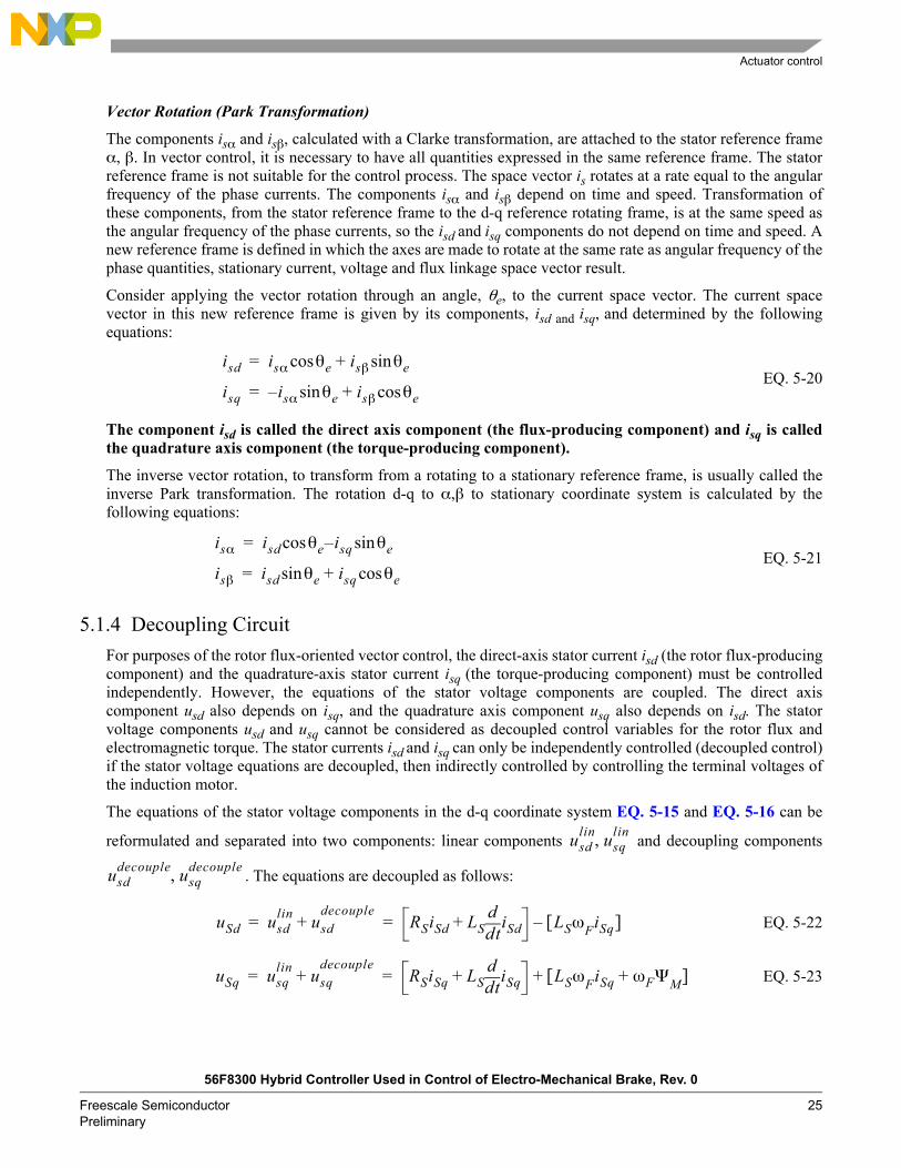
Vector Rotation (Park Transformation)
The components isα and isβ, calculated with a Clarke transformation, are attached to the stator reference frameα, β. In vector control, it is necessary to have all quantities expressed in the same reference frame. The statorreference frame is not suitable for the control process. The space vector is rotates at a rate equal to the angularfrequency of the phase currents. The components isα and isβ depend on time and speed. Transformation ofthese components, from the stator reference frame to the d-q reference rotating frame, is at the same speed asthe angular frequency of the phase currents, so the isd and isq components do not depend on time and speed. Anew reference frame is defined in which the axes are made to rotate at the same rate as angular frequency of thephase quantities, stationary current, voltage and flux linkage space vector result.
Consider applying the vector rotation through an angle, θe, to the current space vector. The current spacevector in this new reference frame is given by its components, isd and isq, and determined by the followingequations:
EQ. 5-20
The component isd is called the direct axis component (the flux-producing component) and isq is calledthe quadrature axis component (the torque-producing component).
The inverse vector rotation, to transform from a rotating to a stationary reference frame, is usually called theinverse Park transformation. The rotation d-q to α,β to stationary coordinate system is calculated by thefollowing equations:
EQ. 5-21
5.1.4 Decoupling CircuitFor purposes of the rotor flux-oriented vector control, the direct-axis stator current isd (the rotor flux-producingcomponent) and the quadrature-axis stator current isq (the torque-producing component) must be controlledindependently. However, the equations of the stator voltage components are coupled. The direct axiscomponent usd also depends on isq, and the quadrature axis component usq also depends on isd. The statorvoltage components usd and usq cannot be considered as decoupled control variables for the rotor flux andelectromagnetic torque. The stator currents isd and isq can only be independently controlled (decoupled control)if the stator voltage equations are decoupled, then indirectly controlled by controlling the terminal voltages ofthe induction motor.
The equations of the stator voltage components in the d-q coordinate system EQ. 5-15 and EQ. 5-16 can be
reformulated and separated into two components: linear components and decoupling components
. The equations are decoupled as follows:
EQ. 5-22
EQ. 5-23
isd isα θe isβ θesin+cos=
isq isα θe isβ θecos+sin=
isα isd θe isq θesincos=
isβ isd θe isq θecos+sin=
usdlin usq
lin,
usddecouple usq
decouple,
uSd usdlin u+ sd
decoupleRSiSd LS td
d iSd+ LSωFiSq[ ]= =
uSq usqlin u+ sq
decoupleRSiSq LS td
d iSq+ LSωFiSq ωFΨM+[ ]+= =

EMB controller
56F8300 Hybrid Controller Used in Control of Electro-Mechanical Brake, Rev. 0
26 Freescale Semiconductor Preliminary
The voltage components are the outputs of the current controllers which control the isd and isq
components. They are added to the decoupling voltage components , creating direct andquadrature components of the terminal output voltage. This means that the voltage on the outputs of the currentcontrollers is:
EQ. 5-24
EQ. 5-25
And the decoupling components are:
EQ. 5-26
EQ. 5-27
As shown, the decoupling algorithm transforms the non-linear motor model to linear equations, which can becontrolled by general PI or PID controllers instead of complicated controllers.
5.1.5 Space Vector Modulation and Inverter Non-Linearity CompensationSpace Vector Modulation (SVM) can directly transform the stator voltage vectors from an α,β coordinatesystem to Pulse Width Modulation (PWM) signals (duty cycle values).
The standard technique of the output voltage generation uses an inverse Clarke transformation to obtain3-phase values. Using the phase voltage values, the duty cycles needed to control the power stage switches arethen calculated. Although this technique gives good results, SVM is more straightforward, although valid onlyfor transformation from the α,β coordinate system.
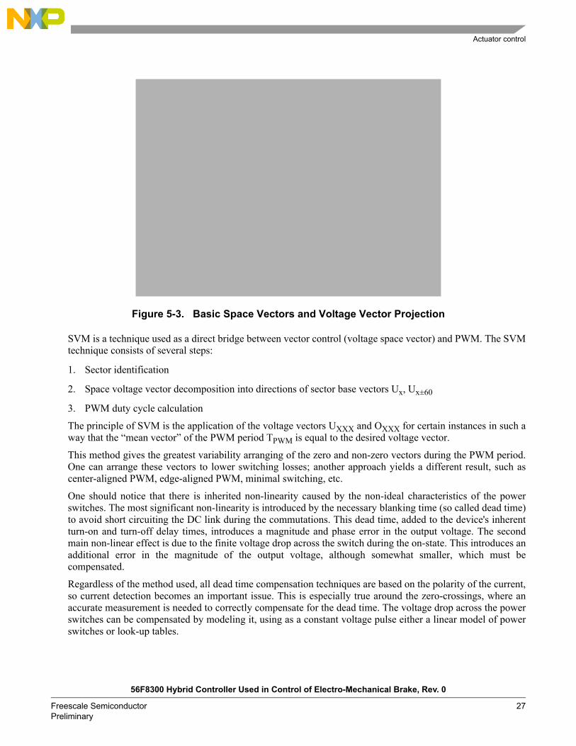
The basic principle of the standard SVM technique can be explained with the help of the power stageschematic diagram depicted in Figure 4-4 Regarding the 3-phase power stage configuration, eight possibleswitching states (vectors) are feasible. They are given by combinations of the corresponding powerswitches.The graphical representation of all combinations is the hexagon shown in Figure 5-3. There are sixnon-zero vectors, U0, U60, U120, U180, U240, U300, and two zero vectors, O000 and O111, defined in α,βcoordinates.
The combination of ON/OFF states of the power stage switches for each voltage vector is coded in Figure 5-3by the three-digit number in parenthesis. Each digit represents one phase. For each phase, a value of one meansthat the upper switch is ON and the bottom switch is OFF. A value of zero means that the upper switch is OFFand the bottom switch is ON.
usdlin usq
lin,
usddecouple usq
decouple,
usdlin RSiSd LS td
d iSd+=
usqlin RSiSq LS td
d iSq+=
usddecouple LSωFiSq=
usqdecouple LSωFiSq ωFΨM+=
Actuator control
56F8300 Hybrid Controller Used in Control of Electro-Mechanical Brake, Rev. 0
Freescale Semiconductor 27Preliminary
Figure 5-3. Basic Space Vectors and Voltage Vector Projection
SVM is a technique used as a direct bridge between vector control (voltage space vector) and PWM. The SVMtechnique consists of several steps:
1. Sector identification
2. Space voltage vector decomposition into directions of sector base vectors Ux, Ux±60
3. PWM duty cycle calculation
The principle of SVM is the application of the voltage vectors UXXX and OXXX for certain instances in such away that the mean vector of the PWM period TPWM is equal to the desired voltage vector.
This method gives the greatest variability arranging of the zero and non-zero vectors during the PWM period.One can arrange these vectors to lower switching losses; another approach yields a different result, such ascenter-aligned PWM, edge-aligned PWM, minimal switching, etc.
One should notice that there is inherited non-linearity caused by the non-ideal characteristics of the powerswitches. The most significant non-linearity is introduced by the necessary blanking time (so called dead time)to avoid short circuiting the DC link during the commutations. This dead time, added to the device's inherentturn-on and turn-off delay times, introduces a magnitude and phase error in the output voltage. The secondmain non-linear effect is due to the finite voltage drop across the switch during the on-state. This introduces anadditional error in the magnitude of the output voltage, although somewhat smaller, which must becompensated.
Regardless of the method used, all dead time compensation techniques are based on the polarity of the current,so current detection becomes an important issue. This is especially true around the zero-crossings, where anaccurate measurement is needed to correctly compensate for the dead time. The voltage drop across the powerswitches can be compensated by modeling it, using as a constant voltage pulse either a linear model of powerswitches or look-up tables.

EMB controller
56F8300 Hybrid Controller Used in Control of Electro-Mechanical Brake, Rev. 0
28 Freescale Semiconductor Preliminary
5.1.6 PI ControllerPI controllers are universally known because of their flexibility and relatively easy tuning. This sectionoutlines the PI representation in continuous and discrete time domains, which is essential for digitalimplementation on hybrid controllers. A numerical routine is then performed, converting the continuous formonto discrete time representation for the PI controller.
The function described here calculates the Proportional-Integral (PI) algorithm according to equationsrepresented in continuous time domain, as follows:
EQ. 5-28
The transition from a continuous to a discrete time domain requires that the integral operation must beapproximated by a discrete numerical integration. There are several methods for replacing the time-continousintegral. Here, the integral is approximated by the Backward Euler approach, also known as the BackwardRectangular method. The PI algorithm in discrete time domain follows:
EQ. 5-29
The values of Kc, and Kc/Ti (known as Ki) must be chosen carefully to ensure a proper transient response. Byproperly designing the PI controller, it is possible to achieve a transient response to a step input that exhibits arelatively small, or even no, overshoot. The transient response, however becomes slower, because the PIcontroller is a low-pass filter, which attenuates the high frequency components of the signal. The phenomenonof wind-up effect is avoided by limiting the integral part with respect to the controller output range. Thisfeature is incorporated into the routines presented herein.
5.1.7 Angle Tracking Observer for ResolverResolvers are absolute angle transducers and are mounted on the motor shaft to get the motors absoluteangular position. Resolvers are often used for angle sensing in a noisy environment due to their ruggedconstruction and their ability to reject common mode noise.The method for obtaining and digitizing the angularposition of a resolver is also known as Resolver-to-Digital conversion (R/D conversion).
u t( ) Kc e t( )1Ti---- e τ( ) τd
0
τ
∫+=
u k( ) Kc e k( ) uI k 1( ) KcTTi---- e k( )⋅ ⋅+ +⋅=
Actuator control
56F8300 Hybrid Controller Used in Control of Electro-Mechanical Brake, Rev. 0
Freescale Semiconductor 29Preliminary
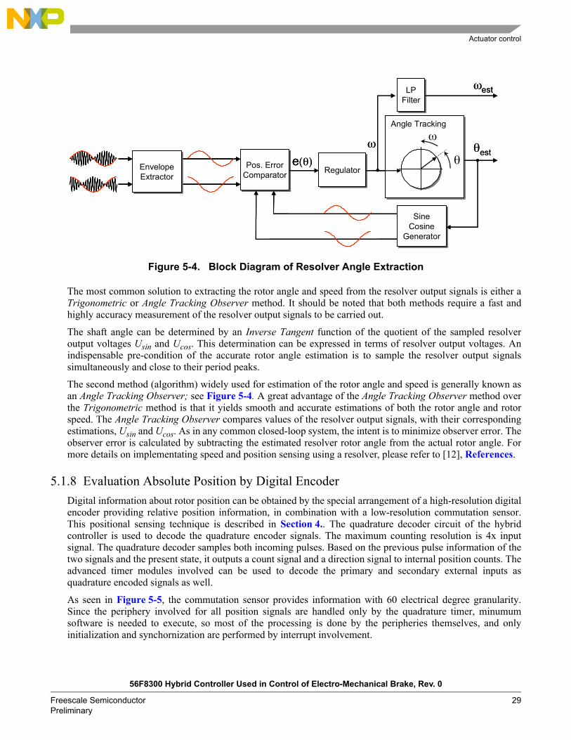
Figure 5-4. Block Diagram of Resolver Angle Extraction
The most common solution to extracting the rotor angle and speed from the resolver output signals is either aTrigonometric or Angle Tracking Observer method. It should be noted that both methods require a fast andhighly accuracy measurement of the resolver output signals to be carried out.
The shaft angle can be determined by an Inverse Tangent function of the quotient of the sampled resolveroutput voltages Usin and Ucos. This determination can be expressed in terms of resolver output voltages. Anindispensable pre-condition of the accurate rotor angle estimation is to sample the resolver output signalssimultaneously and close to their period peaks.
The second method (algorithm) widely used for estimation of the rotor angle and speed is generally known asan Angle Tracking Observer; see Figure 5-4. A great advantage of the Angle Tracking Observer method overthe Trigonometric method is that it yields smooth and accurate estimations of both the rotor angle and rotorspeed. The Angle Tracking Observer compares values of the resolver output signals, with their correspondingestimations, Usin and Ucos. As in any common closed-loop system, the intent is to minimize observer error. Theobserver error is calculated by subtracting the estimated resolver rotor angle from the actual rotor angle. Formore details on implementating speed and position sensing using a resolver, please refer to [12], References.
5.1.8 Evaluation Absolute Position by Digital EncoderDigital information about rotor position can be obtained by the special arrangement of a high-resolution digitalencoder providing relative position information, in combination with a low-resolution commutation sensor.This positional sensing technique is described in Section 4.. The quadrature decoder circuit of the hybridcontroller is used to decode the quadrature encoder signals. The maximum counting resolution is 4x inputsignal. The quadrature decoder samples both incoming pulses. Based on the previous pulse information of thetwo signals and the present state, it outputs a count signal and a direction signal to internal position counts. Theadvanced timer modules involved can be used to decode the primary and secondary external inputs asquadrature encoded signals as well.
As seen in Figure 5-5, the commutation sensor provides information with 60 electrical degree granularity.Since the periphery involved for all position signals are handled only by the quadrature timer, minumumsoftware is needed to execute, so most of the processing is done by the peripheries themselves, and onlyinitialization and synchornization are performed by interrupt involvement.
Pos. Error ComparatorPos. Error
Comparator RegulatorRegulator
Angle TrackingAngle Trackingω
θω
e(θ)Envelope ExtractorEnvelope Extractor
LPFilterLP
Filterωest
θest
SineCosine
Generator
SineCosine
Generator
Pos. Error ComparatorPos. Error
Comparator RegulatorRegulator
Angle TrackingAngle Trackingω
θ
Angle TrackingAngle Trackingω
θω
e(θ)Envelope ExtractorEnvelope Extractor
LPFilterLP
Filterωest
θest
SineCosine
Generator
SineCosine
Generator

EMB controller
56F8300 Hybrid Controller Used in Control of Electro-Mechanical Brake, Rev. 0
30 Freescale Semiconductor Preliminary
Figure 5-5. Absolute Position Encoder Signals
Position information can be evaluated by dedicated peripherals for the 56F8300 microcontroller, where it ispossible to achieve high resolution of the rotor angular position and know the absolute position.
5.2 EMB actuationThe characteristics of each EMB system are determined by both hardware and software. The software plays agreater role in defining the character and brand of the new brake systems in vehicles, and the vehiclemanufacturer, as system integrator, must define the behavior of the vehicle in terms of function, performance,comfort, endurance, safety, etc., to differentiate with respect to competitors.
Figure 5-6. EMB Control System Structure
The base brake function allows interpretation of the drivers demand and the brake actuation systems todecelerate the vehicle. The electronic pedal module contains a device that emulates the desired force versusdisplacement characteristics, as well as the force and travel sensors required to interpret the drivers demand.
Having an architecture with brake clamp force control rather than position control is acceptable during brakeactuation. During stand-by, however, position control is required to manage the air gap between the brake padsand brake rotor. Both modes of operation are achieved by switching between outer position and force controlloops across the contact point between the brake pads and disc brake rotor.
Advanced braking functions such as anti-lock braking, traction control, vehicle stability, and chassis controlallow optimization of vehicle braking and stability, but are not required for basic deceleration performance.
HS_A
HS_C
HS_B
ENC_A
ENC_B
2/3π
π π
Sync Edge Sync Edge
Position
HS_A
HS_C
HS_B
ENC_A
ENC_B
2/3π
π π
Sync Edge Sync Edge
Position
56F8300Controller
Force CommandFd us
ActuatorTm
is & θe
Fcl
Force Sensor
Gear Caliper56F8300Controller
Force CommandFd us
ActuatorTm
is & θe
Fcl
Force Sensor
Gear Caliper

Communication
56F8300 Hybrid Controller Used in Control of Electro-Mechanical Brake, Rev. 0
Freescale Semiconductor 31Preliminary
Another integrated part of the EMB software which can be adopted for running on an ECM is the dedicatedoperating system, as Time-Triggered OSEK, designed according to the time-triggered concept fordeterministic system behavior, and allowing a complete separation of tasks (task encapsulation). If a faulty taskoccurs, the operating system is able to enter a "silent state" (failsilent). A fault-tolerant communication systemconveys the real time image of each of the wheel brake units.
5.3 Air Gap Adjustment of Brake PadsIn contrast to hydraulic brakes, where the clearance of brake pads adjusts automatically when the hydraulicpressure is released, electro-mechanical brakes must actively adjust the clearance by actuator rotor movement.
To perform precise actuator rotor release, the kiss position point of contact between the brake pads and thedisk must be known. The inner brake pad can then be moved to a defined position in order to adjust the desiredclearance. Its also necessary to know the contact point between the pads and the disk because this point is alsothe start braking position, when clamping brake force is about to begin.
The kiss position detection algorithm is first run for initialization of the EMB actuator when the automobilesystem is started. It also processes the brake signals of individual braking applications during normal driving,to preserve the zero value and to continually adapt this kiss position to be more immune to the brake padswear. The car braking behavior is preserved for the drivers comfort, and if an individual brake pad must bereplaced, the EMB controller can issue a notification.
5.4 CommunicationThe existing CAN communication interface and its protocols are not deterministic (able to automaticallytransfer messages at pre-set points), as the timing of messages is not predictable. Because fault-tolerant,safety-critical applications like brake-by-wire systems required that messages must be transferred atpredictable times (deterministic), another communications system is needed.
The FlexRay communication system will support the needs of future in-car control applications. The FlexRaycommunications protocol is at the core of the FlexRay system. It provides flexibility and determinism,incorporating the advantages of familiar synchronous and asynchronous protocols into a scalable static anddynamic message transmission. The protocol also supports:
Fault-tolerant clock synchronization via a global time base Collision-free bus access Guaranteed message latency Message-oriented addressing via identifiers Scalable system fault-tolerance via the support of either single or dual channels

Freescale Solution for EMB System
56F8300 Hybrid Controller Used in Control of Electro-Mechanical Brake, Rev. 0
32 Freescale Semiconductor Preliminary
6. Freescale Solution for EMB SystemTo support Freescales customers who design an EMB system, a complete application core targeted for EMBsystems has been developed, which can be used directly for developing an EMB application and includes bothhardware and software. This EMB application comprises the following features:
System
Field-oriented control of the sinusoidal PMAC with either an attached Hall-effect with encoder or resolver
12/24 VDC 3-phase motor-driving capability CAN, RS-232, and JTAG communication available
Hardware
Single motor controller board 56F8300 CPU 12/24 battery input voltage level Able to drive a 3-phase load Digital encoder inputs Commutation sensor inputs Wheel speed digital inputs Three analog inputs, 0-3.3V/12-bit
Software
Field-oriented control - current control loop Position evaluation based on encoder or resolver Speed measurement PC master software interface
Single Motor Controller Board
56F8300 Hybrid Controller Used in Control of Electro-Mechanical Brake, Rev. 0
Freescale Semiconductor 33Preliminary
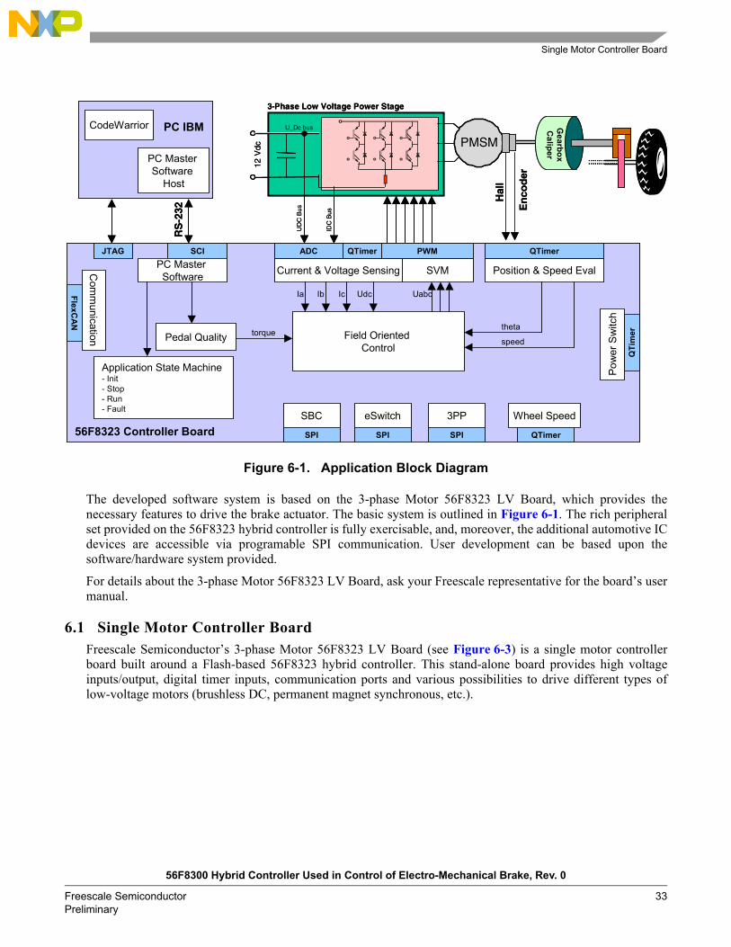
Figure 6-1. Application Block Diagram
The developed software system is based on the 3-phase Motor 56F8323 LV Board, which provides thenecessary features to drive the brake actuator. The basic system is outlined in Figure 6-1. The rich peripheralset provided on the 56F8323 hybrid controller is fully exercisable, and, moreover, the additional automotive ICdevices are accessible via programable SPI communication. User development can be based upon thesoftware/hardware system provided.
For details about the 3-phase Motor 56F8323 LV Board, ask your Freescale representative for the boards usermanual.
6.1 Single Motor Controller BoardFreescale Semiconductors 3-phase Motor 56F8323 LV Board (see Figure 6-3) is a single motor controllerboard built around a Flash-based 56F8323 hybrid controller. This stand-alone board provides high voltageinputs/output, digital timer inputs, communication ports and various possibilities to drive different types oflow-voltage motors (brushless DC, permanent magnet synchronous, etc.).
12 V
dc
3-Phase Low Voltage Power Stage
U_Dc bus
6PMSM6PMSM
En
cod
er
Gearbox
Caliper
IDC
Bus
Hal
l
Field Oriented Control
Pedal Quality
SBC
SPI
eSwitch
SPI
3PP
SPI
Current & Voltage Sensing
ADC QTimer
SVM
PWM
Position & Speed Eval
QTimer
Ia Ib Ic Udc Uabc
theta
speedtorque
UD
C B
us
SCIPC Master Software
Application State Machine- Init- Stop- Run- Fault
Wheel Speed
QTi
mer
Pow
er S
witc
h
PC Master Software
Host
56F8323 Controller Board QTimer
RS
-232
CodeWarrior
JTAG
PC IBM
FlexCA
N
Com
munication

Freescale Solution for EMB System
56F8300 Hybrid Controller Used in Control of Electro-Mechanical Brake, Rev. 0
34 Freescale Semiconductor Preliminary
Figure 6-2. Photo of 56F8300 Motor Controller Board
The single motor controller board includes:
12/24V DC battery input Built-in 60 Amp inverter stage High voltage output of 5 Amp High voltage inputs Polarity protection 1MBit CAN interface RS-232 communication port JTAG debug port User LEDs Digital timer inputs User free ADC input channels Motor back-EMF sensing capability

Single Motor Controller Board
56F8300 Hybrid Controller Used in Control of Electro-Mechanical Brake, Rev. 0
Freescale Semiconductor 35Preliminary
6.1.1 Motor Controller ArchitectureThe 3-phase Motor 56F8323 LV Board facilitates the evaluation of various automotive IC parts as:
An intelligent switch, replacing electro-mechanical relays, fuses, and discrete devices in power devices System-basis chip combining functions such as voltage regulators, high voltage inputs, and high speed
CAN transceiver A 3-phase driver providing an interface between an MCU and the large FETs used to drive 3-phase
loads A 16-bit hybrid controller on a single chip, with the processing power of a Digital Signal Processor
(DSP) and the functionality of a microcontroller with a flexible set of peripherals The 3-phase Motor 56F8323 LV Board provides the necessary features for a user to write and debug software,demonstrate the functionality of this software, and interface with the customer's application-specificarrangement. This 3-phase Motor 56F8323 LV Board can be used to develop real-time software and hardwareproducts based on Freescales automotive IC parts.
An illustration of the board system architecture is shown in Figure 6-3 The key features of the 3-phase Motor56F8323 LV Board are maintained by Freescales automotive IC products. Basic segments of the 3-phaseMotor 56F8323 LV Board appear in this photo:
Input electronic switch by intelligent MC33982 56F8323 microcontroller System-basis support by MC33989 Power stage by SEMIKRON SK115MD10 Power MOSFET driver by MC33896
The board design is optimized for analog control signal measurement, so high fidelity measurement can beachieved.
The 3-phase Motor 56F8323 LV Board is sufficiently flexible to allow a user to fully exploit the features ofFreescales automotive IC part 56F8323, as shown in Figure 6-3.

Freescale Solution for EMB System
56F8300 Hybrid Controller Used in Control of Electro-Mechanical Brake, Rev. 0
36 Freescale Semiconductor Preliminary
Figure 6-3. Block Diagram of 56F8300 Motor Controller Board
6.1.2 Board ConnectivityThe stand-alone 3-phase Motor 56F8323 LV Board contains many features which are programmable andaccessible in connection with supporting development tools, such as Metrowerks CodeWarrior IDE andFreescales PC master software debug utility. A simple preview of the key ICs, connectors, headers, andjumpers can be seen in Figure 6-3.
Integrated circuits: 56F8323, MC33989, MC33896 Connectors: Hall Sensors and Encoder, CAN, RS-232, high voltage input and output, power input,
phase current inputs Terminals: Power input, 3-phase output Jumpers: CAN terminator, MC33896 DC/DC inverter and charge pump Header: JTAG Buttons: Reset, user up and down buttons Switch: User Run/Stop switch Pots: Overcurrent, Overvoltage Integrated circuit: MC33982
µC(56F8300)
Power Supply
Pow
er M
odul
eD
river
Sign
alC
ondi
tioni
ngRS-232
CA
N3-
Ph. P
ower
OU
T
Power Switch High Volt Inputs
JTAG
Slip Encoder Hall
Battery Input
eRelay
Analog Inputs
µC(56F8300)
Power Supply
Pow
er M
odul
eD
river
Sign
alC
ondi
tioni
ngRS-232
CA
N3-
Ph. P
ower
OU
T
Power Switch High Volt Inputs
JTAG
Slip Encoder Hall
Battery Input
eRelay
Analog Inputs

Motor Phase Current Sensing
56F8300 Hybrid Controller Used in Control of Electro-Mechanical Brake, Rev. 0
Freescale Semiconductor 37Preliminary
6.2 Voltage SensingThe DCBus voltage sensor is represented by a simple voltage divider. DCBus voltage does not change rapidlyand is nearly constant, with the ripple given by the battery supply structure. The measured DCBus voltage mustbe filtered to eliminate noise. One of the easiest and fastest techniques is the first order filter, which calculatesthe average filtered value recursively from the last two samples and coefficient C:
EQ. 6-1
To speed up initialization of voltage sensing (the filter has exponential dependency with a constant of 1/Nsamples), the moving average filter, which calculates the average value from the last N samples, can be usedfor initialization:
EQ. 6-2
6.3 Motor Phase Current SensingIt is possible to eliminate or minimize the need for a discrete current sensor for sinusoidal PMAC machines.The 3-phase current values for a sinusoidal PMAC motor can be reconstructed from DC Link currentmeasurements by using a single shunt resistor with appropriate control. The success of such a scheme dependson modifications of the basic PWM algorithm to ensure that the single current sensor is granted access to eachof the three-phase currents in a sufficient period of time.
The phase current feedback signal is proportional to the DCBus current and is provided by the circuitry shownin Figure 6-4 The motor controller board introduced here provides only a DC Link shunt resistor, which isplaced on the negative DCBus rail for motor current sensing. Knowing 3-phase information is required tocontrol a sinusoidal PMAC machine, so advanced sampling and evaluation techniques must be incorporated.
Figure 6-4. DCBus Current Sensing Circuitry
uDCBusFilt n 1+( ) CuDCBusFilt n 1+( ) CuDCBusFilt n( )( ) u DCBusFilt n( )=
uDCBusFilt uDCBus n( )n 1=
N∑=

Freescale Solution for EMB System
56F8300 Hybrid Controller Used in Control of Electro-Mechanical Brake, Rev. 0
38 Freescale Semiconductor Preliminary
6.4 Position and Speed SensingAll devices in Freescales 56F8300 series include a Quadrature Decoder. This peripheral is commonly used forposition and speed sensing. The Quadrature Decoders position counter counts up/down each edge of the PhaseA and Phase B signals according to their order. On each revolution, the position counter might be cleared by anindex pulse, if provided by the encoder sensor.
Field-Oriented Control (FOC), or another named sinusoidal PMAC vector control, requires exact knowledgeof the zero rotor position, where it is assumed that the sinusoidal PMAC rotor is aligned to the d axis in therotating reference frame. Therefore, employing a Quadrature Decoder to decode the encoders signals requireseither the calculation of a position offset, which initializes the Quadrature Decoder position counter tocorrespond with the aligned rotor position (zero position), or the coupling of defined rotor position instanceswith the commutation sensor signals (HS_A, HS_B, HS_C).
To avoid calculation of the rotor position offset, position initialization is performed using the signalinformation from the commutation sensor, which reveals the exact position information every 60 electricaldegree assigned to the individual edge transition. Its necessary to detect this edge transition and exploit thisknowledge to correct the decoder position counter to be precisely aligned with the zero rotor position.
After reset, the position sector of the sinusoidal PMAC rotor can be evaluated using the status of individualHall-effect sensors signals. The Hall-effect sensor status determines the initial position information for thedecoder periphery. Since the position status has 60 electrical granularity, a position counter is initialized intothe center of a particular sector with the InitEncoder variable. The motor control algorithm is provided withthis rough information primarily for motor start-up only, allowing the user to spin the sinusoidal PMAC motorwithout having to move the rotor to an aligned position. This position initialization process is described inFigure 6-5. Additionally, the synchronization variable of edge detection occurrence (RightEdge, LeftEdge) areprepared.
Since the motor control algorithm has adequate position information, the sinusoidal PMAC motor can bedriven correspondingly. If any following movement occurs, inherently generated incoming edges provideprecise information to synchronize the motor control algorithm to the exact rotor position. This isaccomplished by software execution, as depicted in Figure 6-5.
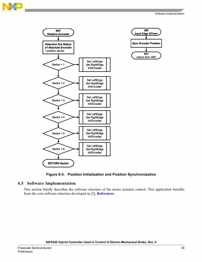
Software Implementation
56F8300 Hybrid Controller Used in Control of Electro-Mechanical Brake, Rev. 0
Freescale Semiconductor 39Preliminary
Figure 6-5. Position Initialization and Position Synchronization
6.5 Software ImplementationThis section briefly describes the software structure of the motor actuator control. This application benefitsfrom the core software structure developed in [2], References.
ISRInput Edge QTimer
Sync Encoder Position
RTI(return form ISR)
ISRInput Edge QTimer
Sync Encoder Position
RTI(return form ISR)
INITRelative Encoder
Detection the Statusof Absolute Encoder position sector
Sector = 1
Sector = 2
Set LeftEdgeSet RightEdge
InitEncoder
Sector = 3
Set LeftEdgeSet RightEdge
InitEncoder
Set LeftEdgeSet RightEdge
InitEncoder
RETURN Sector
Sector = 4
Sector = 5
Sector = 6
Set LeftEdgeSet RightEdge
InitEncoder
Set LeftEdgeSet RightEdge
InitEncoder
Set LeftEdgeSet RightEdge
InitEncoder

Freescale Solution for EMB System
56F8300 Hybrid Controller Used in Control of Electro-Mechanical Brake, Rev. 0
40 Freescale Semiconductor Preliminary
6.5.1 Numeric Value ScalingThe sinusoidal PMAC machine control algorithm and overall application uses a fractional representation for allreal quantities. The N-bit signed fractional format is represented using 1.[N-1] format (1 sign bit, N-1fractional bits). Signed fractional numbers (SF) lie in the following range:
EQ. 6-3
For words and long word signed fractions, the most negative number that can be represented is -1.0, whoseinternal representation is $8000 and $80000000, respectively. The most positive word is $7FFF or 1.0 - 2-15,and the most positive long word is $7FFFFFFF or 1.0 - 2-31
The following equation shows the relationship between a real and a fractional representation:
EQ. 6-4
where:
Fractional Value is the fractional representation of the real value [Frac16]
Real Value is the real value of the quantity [V, A, RPM, etc.]
Real Quantity Range Max is the maximum of the quantity range, defined in the application [V, A, RPM, etc.]
The C language standard does not have any fractional variable type defined. Therefore, fractional operationsare provided by CodeWarrior intrinsic functions (e.g. mult_r() ). As a substitute for fractional type variables,the application uses types Frac16 and Frac32. These are defined as integer 16-bit and 32-bit signed variables.The difference between Frac16 and pure integer variables is that Frac16 and Frac32 declared variables shouldonly be used with fractional operations (intrinsic functions).
A recalculation from a real to a fractional form and a Frac16 or Frac32 value is made through the followingequations:
EQ. 6-5
for Frac16 16-bit signed value and:
EQ. 6-6
for Frac32 32-bit signed value.
EQ. 6-7
Fractional form, a conversion from Fraction Value to Frac16 and Frac32 value, can be provided by the Clanguage macro.
1.0 SF +1.0 -2 N 1[ ]≤ ≤
Fractional Value Real ValueReal Quantity Range--------------------------------------------------=
Frac16 Value 32768 Real ValueReal Quantity Range Max--------------------------------------------------------------⋅=
Frac32 Value 231 Real ValueReal Quantity Range Max--------------------------------------------------------------⋅=
Fractional Value Real ValueReal Quantity Range Max--------------------------------------------------------------=

Actuator Control Algorithms
56F8300 Hybrid Controller Used in Control of Electro-Mechanical Brake, Rev. 0
Freescale Semiconductor 41Preliminary
6.6 Actuator Control AlgorithmsThe benefits of structured modular software design are well known. This is especially true for large complexautomotive systems with many interacting software sub-blocks. As depicted in Figure 5-1, there are severalfunctional blocks needed for the actuator control process, which are available in modular form.
The sinusoidal PMAC control process provides most of the motor control functionality. It is regularly executedmainly in the current processing interrupt. The current processing is called from within ADC CompleteInterrupt, whown in Figure 6-6, once per two PWM reloads, with a period 100µs. It can also be set on eachPWM reload (50µs).
Additionally, there might be a PC master software recorder pcmasterdrvRecorder() routine used to monitor theapplication.
As indicated by the flowchart of the ADC Complete Interrupt Service Routine (ISR), the sampling of analogvalues is processed to gain appropriate information for overall control process and monitoring. This procedureis followed by sensing the digital values of rotor position and speed measurement is performed by softwarecomputation. Knowing the appropriate control information, the PMSM current control is followed andindividual software functional blocks are executed (see Figure 6-6). When the PMSM current control processis performed, the required voltage vector is generated and is ready to apply by updating the PWM valueregisters.
A 56F8300 hybrid controller provides programmable fault protection. Fault protection can disable anycombination of PWM pins. Faults are generated by a logic one on any of the fault pins. Each fault pin can bemapped arbitrarily to any of the PWM pins. When fault protection hardware disables the PWM pins, the PWMgenerator continues to run, and only the output pins are deactivated. If a fault is latched in, it must be clearedand the PWM fault interrupt service routine is invoked (see Figure 6-6) prior to enabling the PWM, to preventan unexpected interrupt.
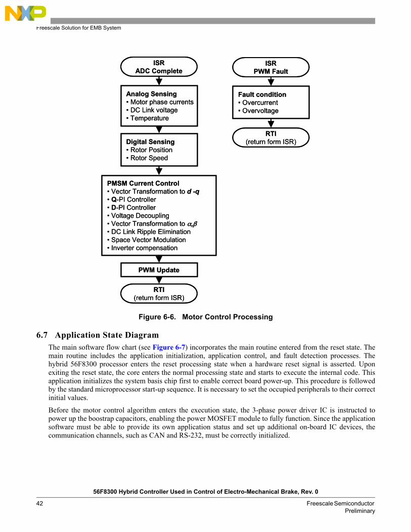
Freescale Solution for EMB System
56F8300 Hybrid Controller Used in Control of Electro-Mechanical Brake, Rev. 0
42 Freescale Semiconductor Preliminary
Figure 6-6. Motor Control Processing
6.7 Application State DiagramThe main software flow chart (see Figure 6-7) incorporates the main routine entered from the reset state. Themain routine includes the application initialization, application control, and fault detection processes. Thehybrid 56F8300 processor enters the reset processing state when a hardware reset signal is asserted. Uponexiting the reset state, the core enters the normal processing state and starts to execute the internal code. Thisapplication initializes the system basis chip first to enable correct board power-up. This procedure is followedby the standard microprocessor start-up sequence. It is necessary to set the occupied peripherals to their correctinitial values.
Before the motor control algorithm enters the execution state, the 3-phase power driver IC is instructed topower up the boostrap capacitors, enabling the power MOSFET module to fully function. Since the applicationsoftware must be able to provide its own application status and set up additional on-board IC devices, thecommunication channels, such as CAN and RS-232, must be correctly initialized.
ISRADC Complete
Analog Sensing Motor phase currents DC Link voltage Temperature
Digital Sensing Rotor Position Rotor Speed
PMSM Current Control Vector Transformation to d -q Q-PI Controller D-PI Controller Voltage Decoupling Vector Transformation to α,β DC Link Ripple Elimination Space Vector Modulation Inverter compensation
RTI(return form ISR)
PWM Update
ISRPWM Fault
Fault condition Overcurrent Overvoltage
RTI(return form ISR)
ISRPWM Fault
Fault condition Overcurrent Overvoltage
RTI(return form ISR)

Application State Diagram
56F8300 Hybrid Controller Used in Control of Electro-Mechanical Brake, Rev. 0
Freescale Semiconductor 43Preliminary
Application control is a software mechanism incorporating a state machine which governs the overallapplication operation, and upon available data, runs appropriate software states. In run-time conditions, thehardware status, such as temperature, IC device status, and so on, is monitored.
Figure 6-7. Main Software Flowchart
The application state control is depicted in Figure 6-8 in more detail, and reveals the application software inthe state machine form. When the normal execution state of the hybrid controller is entered, the software startsexecuting the INIT state, and the initialization procedures take place. As soon as the initialization is performed,the state corresponding to the condition of the control variables is entered.
The STOP state provides an actuator standstill. In the STOP state, the brake drive is disabled, PWM outputpads are disabled, and the PMSM current control process is called by the ADC Complete ISR. The applicationwaits for the start command. If any fault is detected in the STOP state, the application enters the FAULT state.If no fault is present and the start command is accepted, the application transits to the RUN state, and electricmotor actuation is started upon the brake command.
The RUN state can be entered from the STOP state. The RUN state performs a motor brake actuation. In theRUN state, the brake drive is enabled and the actuator develops the appropriate shaft torque in the brakemechanism. The PWM output pads are enabled and the full PMSM current control process is called by theADC Complete ISR. If any fault in the RUN state is detected, the application enters the FAULT state.
The FAULT state can be entered from any state. In the FAULT state, the brake actuator is disabled and theapplication waits for the fault to be cleared. When it detects that the fault has disappeared and the fault clearcommand is accepted, the switch command is moved to the stop position and the application transits to theINIT state.
POR(Power-On Reset)
Application Initialization
Application Control
Fault Detection
SBC Servicing
56F8300 Start-Up Peripheral Initialization
3-phase Driver Initialization
Communication Initialization CAN RS-232
POR(Power-On Reset)
Application Initialization
Application Control
Fault Detection
SBC Servicing
56F8300 Start-Up Peripheral Initialization
3-phase Driver Initialization
Communication Initialization CAN RS-232

Freescale Solution for EMB System
56F8300 Hybrid Controller Used in Control of Electro-Mechanical Brake, Rev. 0
44 Freescale Semiconductor Preliminary
Figure 6-8. Generic Application State Machine
INIT
STOP
RUNFAULT
START
Min < Voltage < Max
Overvoltage detectionUndervoltage detectionCommunication lost
Min < Voltage < MaxCommunication restored
Overvoltage detectionUndervoltage detection
INIT
STOP
RUNFAULT
START
Min < Voltage < Max
Overvoltage detectionUndervoltage detectionCommunication lost
Min < Voltage < MaxCommunication restored
Overvoltage detectionUndervoltage detection

Application State Diagram
56F8300 Hybrid Controller Used in Control of Electro-Mechanical Brake, Rev. 0
Freescale Semiconductor 45Preliminary
7. References1. Bose, K. B. (2002). Modern Power Electronics and AC Drives, Prentice Hall, Inc. ISBN 0-13-016743-6,
New York.
2. 3-Phase PM Synchronous Motor Torque Vector Control Using 56F805, DRM018/D, Freescale Semiconductor, Inc.
3. Ch. Line, Ch. Manzie and M. Good (2004). Control of an Electromechanical Brake for Automotive Brake-By-Wire Systems with an Adapted Motion Control Architecture, SAE Automotive Dynamics, Stability & Controls Conference and Exhibition, P-386, Detroit, Michigan
4. R. Schwarz, R. Isermann, J. Böhm, J. Nell and P. Rieth (1999). Clamping Force Estimation for a Brake-by-Wire Actuator, International Congress and Exposition Detroit, SP-1413, Detroit, Michigan.
5. I. Petersen (2003). Wheel Slip Control in ABS Brakes using Gain Scheduled Optimal Control with Constraints, PhD. Thesis, NUST Trondheim, Norway
6. N. A. Kelling, and W. Heck (2002), The BRAKE Project - Centralized Versus Distributed Redundancy for Brake-by-Wire Systems, SAE 2002 World Congress, SP-1658, Detroit, Michigan
7. D. F. Reuter, E. W. Lloyd, J. W. Zehnder II and J. A. Elliott (2003). Hydraulic Design Considerations for EHB Systems, 2003 SAE World Congress, SP-1780, Detroit, Michigan
8. J. Langenwalter and B. Kelly (2003), Virtual Design of a 42V Brake-by-Wire System, SAE 2003 World Congress & Exhibition, SP-1769, Detroit, Michigan
9. Electro-mechanical Braking (Brake-By-Wire), SG2008, Freescale Semiconductor, Inc.
10. DSP56800E Reference Manual, DSP56F800ERM, Freescale Semiconductor, Inc.
11. 56F8300 Peripheral User Manual, MC56F8300UM, Freescale Semiconductor, Inc.
12. DSP56F80x Resolver Driver and Hardware Interface, AN1942, Freescale Semiconductor, Inc.

References
56F8300 Hybrid Controller Used in Control of Electro-Mechanical Brake, Rev. 0
46 Freescale Semiconductor Preliminary

Application State Diagram
56F8300 Hybrid Controller Used in Control of Electro-Mechanical Brake, Rev. 0
Freescale Semiconductor 47Preliminary

How to Reach Us:
Home Page:www.freescale.com
E-mail:[email protected]
USA/Europe or Locations Not Listed:Freescale SemiconductorTechnical Information Center, CH3701300 N. Alma School RoadChandler, Arizona 85224+1-800-521-6274 or [email protected]
Europe, Middle East, and Africa:Freescale Halbleiter Deutschland GmbHTechnical Information CenterSchatzbogen 781829 Muenchen, Germany+44 1296 380 456 (English)+46 8 52200080 (English)+49 89 92103 559 (German)+33 1 69 35 48 48 (French)[email protected]
Japan:Freescale Semiconductor Japan Ltd.HeadquartersARCO Tower 15F1-8-1, Shimo-Meguro, Meguro-ku,Tokyo 153-0064, Japan0120 191014 or +81 3 5437 [email protected]
Asia/Pacific:Freescale Semiconductor Hong Kong Ltd.Technical Information Center2 Dai King StreetTai Po Industrial EstateTai Po, N.T., Hong Kong+800 2666 [email protected]
For Literature Requests Only:Freescale Semiconductor Literature Distribution CenterP.O. Box 5405Denver, Colorado 802171-800-441-2447 or 303-675-2140Fax: [email protected]
Freescale and the Freescale logo are trademarks of Freescale Semiconductor, Inc. All other product or service names are the property of their respective owners.This product incorporates SuperFlash® technology licensed from SST.© Freescale Semiconductor, Inc. 2004. All rights reserved.
AN1999Rev. 011/2004
Information in this document is provided solely to enable system and software implementers to use Freescale Semiconductor products. There are no express or implied copyright licenses granted hereunder to design or fabricate any integrated circuits or integrated circuits based on the information in this document.
Freescale Semiconductor reserves the right to make changes without further notice to any products herein. Freescale Semiconductor makes no warranty, representation or guarantee regarding the suitability of its products for any particular purpose, nor does Freescale Semiconductor assume any liability arising out of the application or use of any product or circuit, and specifically disclaims any and all liability, including without limitation consequential or incidental damages. Typical parameters that may be provided in Freescale Semiconductor data sheets and/or specifications can and do vary in different applications and actual performance may vary over time. All operating parameters, including Typicals, must be validated for each customer application by customers technical experts. Freescale Semiconductor does not convey any license under its patent rights nor the rights of others. Freescale Semiconductor products are not designed, intended, or authorized for use as components in systems intended for surgical implant into the body, or other applications intended to support or sustain life, or for any other application in which the failure of the Freescale Semiconductor product could create a situation where personal injury or death may occur. Should Buyer purchase or use Freescale Semiconductor products for any such unintended or unauthorized application, Buyer shall indemnify and hold Freescale Semiconductor and its officers, employees, subsidiaries, affiliates, and distributors harmless against all claims, costs, damages, and expenses, and reasonable attorney fees arising out of, directly or indirectly, any claim of personal injury or death associated with such unintended or unauthorized use, even if such claim alleges that Freescale Semiconductor was negligent regarding the design or manufacture of the part.