(575v ac) manual - rockwell automationliterature.rockwellautomation.com/.../documents/um/130… ·...
TRANSCRIPT
1302 AC Drive(575V AC)
Version 3.1
UserManual
Solid state equipment has operational characteristics differing fromthose of electromechanical equipment. “Safety Guidelines for theApplication, Installation and Maintenance of Solid State Controls”(Publication SGI-1.1) describes some important differences betweensolid state equipment and hard–wired electromechanical devices.Because of this difference, and also because of the wide variety ofuses for solid state equipment, all persons responsible for applyingthis equipment must satisfy themselves that each intendedapplication of this equipment is acceptable.
In no event will the Allen-Bradley Company be responsible or liablefor indirect or consequential damages resulting from the use orapplication of this equipment.
The examples and diagrams in this manual are included solely forillustrative purposes. Because of the many variables andrequirements associated with any particular installation, theAllen-Bradley Company cannot assume responsibility or liability foractual use based on the examples and diagrams.
No patent liability is assumed by Allen-Bradley Company withrespect to use of information, circuits, equipment, or softwaredescribed in this manual.
Reproduction of the contents of this manual, in whole or in part,without written permission of the Allen-Bradley Company isprohibited.
Throughout this manual we use notes to make you aware of safetyconsiderations.
!ATTENTION: Identifies information about practicesor circumstances that can lead to personal injury ordeath, property damage, or economic loss.
Attentions help you:
• identify a hazard
• avoid the hazard
• recognize the consequences
Important: Identifies information that is especially important forsuccessful application and understanding of the product.
SCANport is a trademark of Allen-Bradley Company, Inc.PLC is a registered trademark of Allen-Bradley Company, Inc.COLOR-KEYED is a registered trademark of Thomas & Betts CorporationTaptite is a registered trademark of Research Engineering and Manufacturing, Inc.
Important User Information

Publication 1302-5.0 — January, 1998
Chapter 1
Manual Objectives 1-1. . . . . . . . . . . . . . . . . . . . . . . . . . . . . . . . . . . .
Chapter 2
Introduction 2-1. . . . . . . . . . . . . . . . . . . . . . . . . . . . . . . . . . . . . . . . . Standard Features 2-1. . . . . . . . . . . . . . . . . . . . . . . . . . . . . . . . . . . . Drive Description 2-2. . . . . . . . . . . . . . . . . . . . . . . . . . . . . . . . . . . . . System Diagram 2-3. . . . . . . . . . . . . . . . . . . . . . . . . . . . . . . . . . . . . Model Numbers 2-6. . . . . . . . . . . . . . . . . . . . . . . . . . . . . . . . . . . . . . Enclosure Ratings 2-7. . . . . . . . . . . . . . . . . . . . . . . . . . . . . . . . . . . . Component Locations 2-7. . . . . . . . . . . . . . . . . . . . . . . . . . . . . . . . . Option Kits 2-7. . . . . . . . . . . . . . . . . . . . . . . . . . . . . . . . . . . . . . . . .
Chapter 3
General 3-1. . . . . . . . . . . . . . . . . . . . . . . . . . . . . . . . . . . . . . . . . . . Site Requirements 3-2. . . . . . . . . . . . . . . . . . . . . . . . . . . . . . . . . . . . Cooling Airflow 3-4. . . . . . . . . . . . . . . . . . . . . . . . . . . . . . . . . . . . . . Wiring Requirements 3-4. . . . . . . . . . . . . . . . . . . . . . . . . . . . . . . . . . Input Fusing 3-7. . . . . . . . . . . . . . . . . . . . . . . . . . . . . . . . . . . . . . . . Emergency Stop Installation 3-8. . . . . . . . . . . . . . . . . . . . . . . . . . . . . Motor Considerations 3-9. . . . . . . . . . . . . . . . . . . . . . . . . . . . . . . . . .
Chapter 4
Introduction 4-1. . . . . . . . . . . . . . . . . . . . . . . . . . . . . . . . . . . . . . . . . Mounting the Drive 4-1. . . . . . . . . . . . . . . . . . . . . . . . . . . . . . . . . . . . Routing Wires 4-1. . . . . . . . . . . . . . . . . . . . . . . . . . . . . . . . . . . . . . . External Component Installation 4-4. . . . . . . . . . . . . . . . . . . . . . . . . . Setting the Analog Input Jumper on the Regulator Board 4-6. . . . . . . . . Motor Preparation 4-5. . . . . . . . . . . . . . . . . . . . . . . . . . . . . . . . . . . .
Chapter 5
Introduction 5-1. . . . . . . . . . . . . . . . . . . . . . . . . . . . . . . . . . . . . . . . . Signal and Control Wiring 5-3. . . . . . . . . . . . . . . . . . . . . . . . . . . . . . . Digital Input Wiring 5-4. . . . . . . . . . . . . . . . . . . . . . . . . . . . . . . . . . . . Output Power Wiring 5-10. . . . . . . . . . . . . . . . . . . . . . . . . . . . . . . . . . Grounding 5-10. . . . . . . . . . . . . . . . . . . . . . . . . . . . . . . . . . . . . . . . . .
Table of Contents
Introduction
Drive Description
Preinstallation
Installation
Drive Wiring

Table of Contentsii
Publication 1302-5.0 — January, 1998
Chapter 6
Introduction 6-1. . . . . . . . . . . . . . . . . . . . . . . . . . . . . . . . . . . . . . . . . Power Off Checks 6-1. . . . . . . . . . . . . . . . . . . . . . . . . . . . . . . . . . . . Operational Checks 6-3. . . . . . . . . . . . . . . . . . . . . . . . . . . . . . . . . . .
Chapter 7
Introduction 7-1. . . . . . . . . . . . . . . . . . . . . . . . . . . . . . . . . . . . . . . . . Display Description 7-1. . . . . . . . . . . . . . . . . . . . . . . . . . . . . . . . . . . Key Description 7-2. . . . . . . . . . . . . . . . . . . . . . . . . . . . . . . . . . . . . . LED Descriptions 7-3. . . . . . . . . . . . . . . . . . . . . . . . . . . . . . . . . . . . . Program Mode 7-4. . . . . . . . . . . . . . . . . . . . . . . . . . . . . . . . . . . . . . Monitor Mode 7-6. . . . . . . . . . . . . . . . . . . . . . . . . . . . . . . . . . . . . . . Drive Control 7-8. . . . . . . . . . . . . . . . . . . . . . . . . . . . . . . . . . . . . . . .
Chapter 8
Introduction 8-1. . . . . . . . . . . . . . . . . . . . . . . . . . . . . . . . . . . . . . . . . Program Security 8-2. . . . . . . . . . . . . . . . . . . . . . . . . . . . . . . . . . . . . Parameter Descriptions 8-4. . . . . . . . . . . . . . . . . . . . . . . . . . . . . . . .
Chapter 9
Introduction 9-1. . . . . . . . . . . . . . . . . . . . . . . . . . . . . . . . . . . . . . . . . Verifying DC Bus Voltage 9-1. . . . . . . . . . . . . . . . . . . . . . . . . . . . . . . Troubleshooting the Drive Using Fault Codes 9-2. . . . . . . . . . . . . . . . . Accessing and Clearing the Error Log 9-5. . . . . . . . . . . . . . . . . . . . . . Power Module Check 9-7. . . . . . . . . . . . . . . . . . . . . . . . . . . . . . . . . .
Appendix A
Service Conditions A-1. . . . . . . . . . . . . . . . . . . . . . . . . . . . . . . . . . . . Dimensions A-1. . . . . . . . . . . . . . . . . . . . . . . . . . . . . . . . . . . . . . . . . Environmental Conditions A-1. . . . . . . . . . . . . . . . . . . . . . . . . . . . . . . Drive Inputs A-2. . . . . . . . . . . . . . . . . . . . . . . . . . . . . . . . . . . . . . . . . Drive Outputs A-2. . . . . . . . . . . . . . . . . . . . . . . . . . . . . . . . . . . . . . .
Appendix B
Parameter Table B–1. . . . . . . . . . . . . . . . . . . . . . . . . . . . . . . . . . . . .
Appendix C
Parameter List C–1. . . . . . . . . . . . . . . . . . . . . . . . . . . . . . . . . . . . . . .
Appendix D
Parts Table D–1. . . . . . . . . . . . . . . . . . . . . . . . . . . . . . . . . . . . . . . . .
Final Installation Checks
Display and KeypadOperation
Programming
Troubleshooting
Technical Specifications
User Settings Record
Alphabetical ParameterListing
Replacement Parts
Chapter 11–1
Publication 1302-5.0 — January, 1998
Introduction
The purpose of this manual is to provide you with the necessaryinformation to install, program, start up and maintain the 1302 ACDrive. This manual should be read in its entirety before operating,servicing or initializing the 1302 Drive.
This manual is intended for qualified electrical personnel responsiblefor installing, programming, starting up, and maintaining the 1302drive.This manual describes how to install and troubleshoot the 1302 ACdrive. Drive installation consists of the following basic tasks:• Plan your installation using the guidelines presented in chapter 3.
If your installation must be in compliance with Electromagnetic Compatibility Standards, read Appendix E also.
• Mount the Drive and install external components according to the guidelines presented in chapter 4.
• Wire the Drive’s input power, output power, and control signal terminal strip using the instructions in chapter 5.
• Adjust parameter values, if required. The parameters are described in chapter 8. For quick reference, the factory-set values are listed in Appendix B.
• Perform the power-off and power-on checks described in chapter6 to complete the installation.
If problems occur during Drive operation, refer to chapter 9.Appendix F lists the parts of the Drive that can be replaced. Beforeyou begin the installation procedure, become familiar with the Driveby reading chapter 2, which provides an overview of the Drive andits features, chapter 7, which describes the operation of the keypadand the display, and Appendix A, which lists the Drive’s technicalspecifications.
Manual Objectives

1–2 Introduction
Publication 1302-5.0 — January, 1998
!ATTENTION: Only qualified electrical personnelfamiliar with the construction and operation of thisequipment and the hazards involved should install,adjust, operate and/or service this equipment. Read andunderstand this section in its entirety beforeproceeding. Failure to observe this precaution couldresult in bodily injury or loss of life.
ATTENTION: An incorrectly installed or appliedDrive can result in component damage or a reductionin product life. Wiring or application errors such asundersizing the motor, incorrect or inadequate ACsupply or excessive ambient temperatures may result indamage to the Drive or motor.
ATTENTION: This Drive contains ESD(Electrostatic Discharge) sensitive parts andassemblies. Static control precautions are requiredwhen installing, testing, servicing or repairing thisassembly. Component damage may result if ESDcontrol procedures are not followed. If you are notfamiliar with static control procedures, referenceAllen–Bradley Publication 8000 – 4.5.2, Guardingagainst Electrostatic Damage or any other applicableESD protection handbook.
Chapter 22–1
Publication 1302-5.0 — January, 1998
1302 AC Drive Description
This chapter describes the 1302 Drive and how to identify it basedon its model number. This chapter also provides power andenclosure rating information.
The 1302 Drive has the following features:
• On-board keypad and display providing:Start/Stop/Reset controlForward/Reverse (reverse-disable selectable)Setpoint adjustment, Motor RPM, %load, or output voltage displayDrive diagnostics
• 500 millisecond power dip ride-through• 150% overload for one minute• 0.5 to 240 Hz three-phase voltage output• NEMA 1 and NEMA 4/12 enclosures• A snubber resistor braking signal and a scaled voltage analog
output (0 to 10 VDC) which is proportional to:Output frequencyOutput ampsOutput voltageSelected reference
• Quiet motor operation with high carrier frequency selection
• Drive protection: Overcurrent Short circuit Ground fault Overvoltage Undervoltage Overtemperature
• UL/CSA electronic overload that meets NEC/CEC requirements
• User-selectable relay contact for indications of Drive running, Drive faulted, or Drive at selected speed
• User-selectable power-up start, auto-restart, and coast-to-rest or ramp-to-rest stop functions
• User-selectable local or remote operation
• 29 user–adjustable software parameters
Introduction
Standard Features
2–2 1302 AC Drive Description
Publication 1302-5.0 — January, 1998
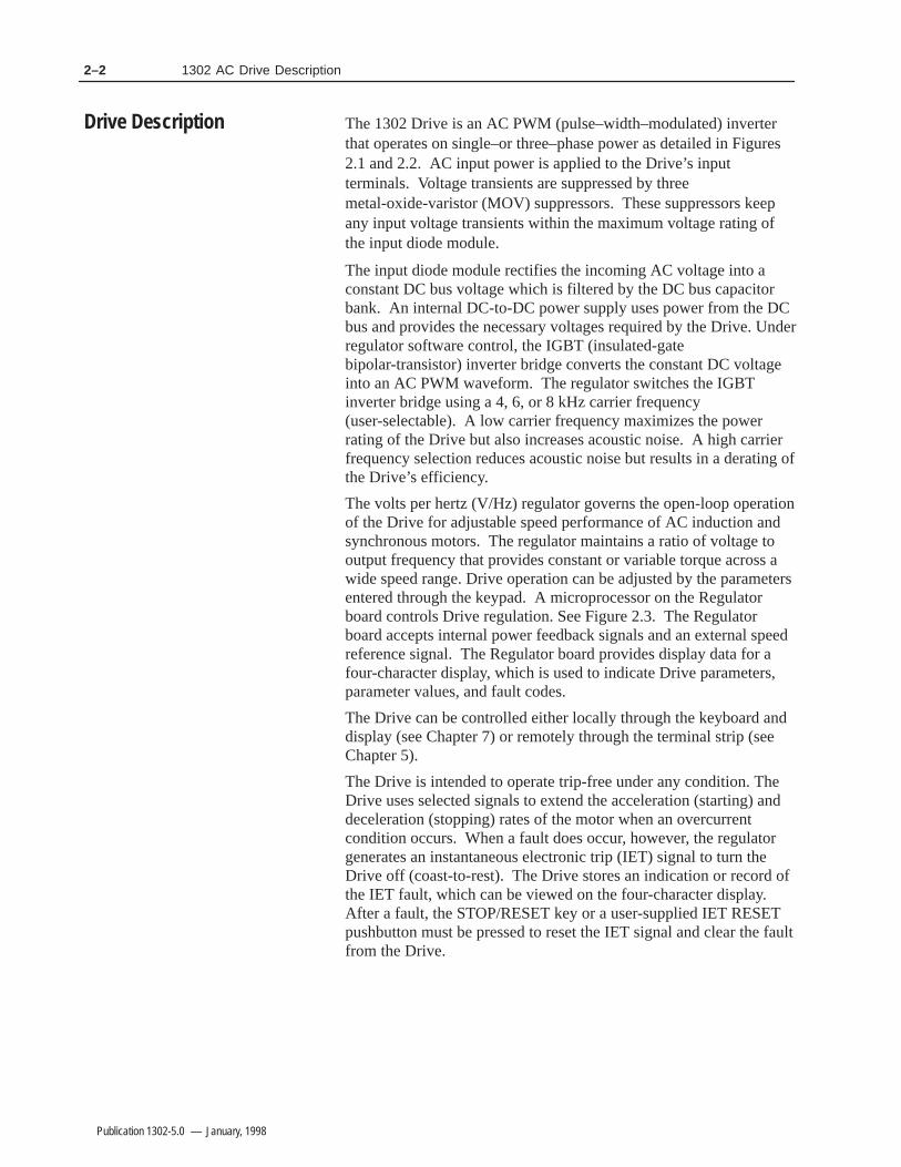
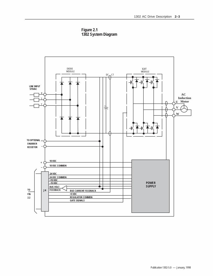
The 1302 Drive is an AC PWM (pulse–width–modulated) inverterthat operates on single–or three–phase power as detailed in Figures2.1 and 2.2. AC input power is applied to the Drive’s inputterminals. Voltage transients are suppressed by threemetal-oxide-varistor (MOV) suppressors. These suppressors keepany input voltage transients within the maximum voltage rating ofthe input diode module.
The input diode module rectifies the incoming AC voltage into a constant DC bus voltage which is filtered by the DC bus capacitor bank. An internal DC-to-DC power supply uses power from the DC bus and provides the necessary voltages required by the Drive. Underregulator software control, the IGBT (insulated-gate bipolar-transistor) inverter bridge converts the constant DC voltage into an AC PWM waveform. The regulator switches the IGBT inverter bridge using a 4, 6, or 8 kHz carrier frequency (user-selectable). A low carrier frequency maximizes the power rating of the Drive but also increases acoustic noise. A high carrier frequency selection reduces acoustic noise but results in a derating ofthe Drive’s efficiency.
The volts per hertz (V/Hz) regulator governs the open-loop operationof the Drive for adjustable speed performance of AC induction and synchronous motors. The regulator maintains a ratio of voltage to output frequency that provides constant or variable torque across a wide speed range. Drive operation can be adjusted by the parameters entered through the keypad. A microprocessor on the Regulator board controls Drive regulation. See Figure 2.3. The Regulator board accepts internal power feedback signals and an external speedreference signal. The Regulator board provides display data for a four-character display, which is used to indicate Drive parameters, parameter values, and fault codes.
The Drive can be controlled either locally through the keyboard and display (see Chapter 7) or remotely through the terminal strip (see Chapter 5).
The Drive is intended to operate trip-free under any condition. The Drive uses selected signals to extend the acceleration (starting) and deceleration (stopping) rates of the motor when an overcurrent condition occurs. When a fault does occur, however, the regulator generates an instantaneous electronic trip (IET) signal to turn the Drive off (coast-to-rest). The Drive stores an indication or record of the IET fault, which can be viewed on the four-character display. After a fault, the STOP/RESET key or a user-supplied IET RESET pushbutton must be pressed to reset the IET signal and clear the faultfrom the Drive.
Drive Description
2–31302 AC Drive Description
Publication 1302-5.0 — January, 1998
Figure 2.11302 System Diagram
U
POWERSUPPLY
V
W
J4TO
GATE SIGNALSREGULATOR COMMON+5 VDCBUS CURRENT FEEDBACK
BUS VOLTFEEDBACK
–15 VDC+15 VDC24 VDC COMMON24 VDC
10 VDC COMMON
10 VDC
ACInduction Motor
FIG2.2
+–
TO OPTIONAL SNUBBER RESISTOR
+
–
+
IGBTMODULE
DIODEMODULE
R
S
T
DC CT
LINE INPUT 575VAC

2–4 1302 AC Drive Description
Publication 1302-5.0 — January, 1998
Figure 2.21302 System Diagram Cont.

2–51302 AC Drive Description
Publication 1302-5.0 — January, 1998
%%%%%%%%%$$$$$$
!#
&
! "
&
Figure 2.3Regulator Board Component Locations
2–6 1302 AC Drive Description
Publication 1302-5.0 — January, 1998
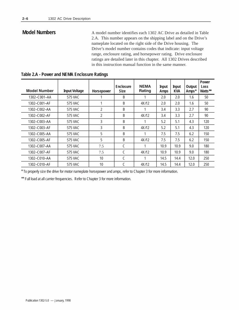
A model number identifies each 1302 AC Drive as detailed in Table2.A. This number appears on the shipping label and on the Drive’snameplate located on the right side of the Drive housing. TheDrive’s model number contains codes that indicate: input voltagerange, enclosure rating, and horsepower rating. Drive enclosureratings are detailed later in this chapter. All 1302 Drives describedin this instruction manual function in the same manner.
Table 2.A - Power and NEMA Enclosure Ratings
Input Voltage HorsepowerEnclosure Size
Input Amps
Input KVA
OutputAmps*
Power LossWatts**
1302–C001–AA 575 VAC 1 B 1 2.0 2.0 1.6 50
1302–C001–AF 575 VAC 1 B 4X/12 2.0 2.0 1.6 50
1302–C002–AA 575 VAC 2 B 1 3.4 3.3 2.7 90
1302–C002–AF 575 VAC 2 B 4X/12 3.4 3.3 2.7 90
1302–C003–AA 575 VAC 3 B 1 5.2 5.1 4.3 120
1302–C003–AF 575 VAC 3 B 4X/12 5.2 5.1 4.3 120
1302–C005–AA 575 VAC 5 B 1 7.5 7.5 6.2 150
1302–C005–AF 575 VAC 5 B 4X/12 7.5 7.5 6.2 150
1302–C007–AA 575 VAC 7.5 C 1 10.9 10.9 9.0 180
1302–C007–AF 575 VAC 7.5 C 4X/12 10.9 10.9 9.0 180
1302–C010–AA 575 VAC 10 C 1 14.5 14.4 12.0 250
1302–C010–AF 575 VAC 10 C 4X/12 14.5 14.4 12.0 250
* To properly size the drive for motor nameplate horsepower and amps, refer to Chapter 3 for more information.
** Full load at all carrier frequencies. Refer to Chapter 3 for more information.
Model Numbers

2–71302 AC Drive Description
Publication 1302-5.0 — January, 1998
Each 1302 Drive has one of the following ratings:
Table 2.B - 1302 NEMA Ratings
(. ), " ( ,&3*/,*)- $()), **&$.$)(-
). 0 (. /**&$ 1$.# - ( % 2* "-% .- ), /- $( $()), (0$,)(' (.- .#. , +/$, 1. ,3.$"#. ( /-.3.$"#. (&)-/, ( (&)-/, 1$.# .#$- ,.$(" ()'*-- - ).# ,.$("- (
(. ( !), /- $( $()), (0$,)(' (.- .#. , +/$, /-.3.$"#. (,$*3.$"#. (&)-/,
For clarity in this manual, 1302 Drive enclosures are identified by size as enclosures B orC. Refer to Chapter 3 for the dimensions of enclosures B through C.
Figures 2.4 and 2.5 show the main components of the 1302 Drives(enclosures B and C). Appendix F lists replacement parts.
The option kit which is available for the 1302 Drive is detailed inTable 2.C.
Table 2.C - 1302 Option Kits
)1 ( ,"2 (/ , -$-.), ,%$(" $. !), ,$0 -
** Snubber resistor braking kits require connection to the snubber resistor braking 10V power supply. SeeChapter 5 (Snubber resistor wiring) for more information.
Enclosure Ratings
Component Locations
Option Kits

2–8 1302 AC Drive Description
Publication 1302-5.0 — January, 1998
Figure 2.4Enclosure B Component Locations

2–91302 AC Drive Description
Publication 1302-5.0 — January, 1998
Figure 2.5Enclosure C Component Locations

2–10 1302 AC Drive Description
Publication 1302-5.0 — January, 1998
This Page Intentionally Blank

2–111302 AC Drive Description
Publication 1302-5.0 — January, 1998

2–12 1302 AC Drive Description
Publication 1302-5.0 — January, 1998
Table 2.A1302 Model Number Notation
Model Number Input Voltage Horsepower1.52357.5101520253040506075100125150
6.2 Nm (55 lb-in)6.2 Nm (55 lb-in)6.2 Nm (55 lb-in)6.2 Nm (55 lb-in)6.2 Nm (55 lb-in)6.2 Nm (55 lb-in)13.6 Nm (120 lb-in)13.6 Nm (120 lb-in)13.6 Nm (120 lb-in)13.6 Nm (120 lb-in)22 Nm (200 lb-in)22 Nm (200 lb-in)22 Nm (200 lb-in)22 Nm (200 lb-in)
——
——6.2 Nm (55 lb-in)6.2 Nm (55 lb-in)6.2 Nm (55 lb-in)6.2 Nm (55 lb-in)6.2 Nm (55 lb-in)6.2 Nm (55 lb-in)6.2 Nm (55 lb-in)13.6 Nm (120 lb-in)13.6 Nm (120 lb-in)13.6 Nm (120 lb-in)13.6 Nm (120 lb-in)22 Nm (200 lb-in)22 Nm (200 lb-in)22 Nm (200 lb-in)22 Nm (200 lb-in)
Note:
115VAC Option Board CON 2115VAC Thermostat/Brush Wear Circuit
12
13
14
BRUSH WEAR
MOTOR THERMOSTAT
115V HI
Figure 2.19Motor Thermostat/Brush Wear Wiring

Chapter 33–1
Publication 1302-5.0 — January, 1998
1302 Preinstallation
Chapter 3 provides information that you must use when planning a1302 AC Drive installation. Installation site, wiring and motorapplication requirements are included in this chapter.
!ATTENTION: The following information is merely aguide for proper installation. The National ElectricalCode and any other governing regional or local codewill overrule this information. The Allen–BradleyCompany cannot assume responsibility for thecompliance or noncompliance to any code, national,local or otherwise for the proper installation of thisDrive or associated equipment. A hazard of personalinjury and/or equipment damage exists if codes areignored during installation.
ATTENTION: Hazard of electric shock or equipmentdamage exist if the Drive is not installed correctly. TheNational Electrical Code (NEC) and local codes outlineprovisions for safely installing electrical equipment.Installation must comply with specifications regardingwire types, conductor sizes, branch circuit protectionand disconnect devices. Only qualified electricalpersonnel familiar with the construction and operationof the 1302 Drive and the hazards involved shouldinstall, adjust, operate, or service this equipment. Readand understand this manual and other applicable manu-als in their entirety before proceeding. Failure to do somay result in personal injury and/or equipmentdamage.
!
General
3–2 1302 Preinstallation
Publication 1302-5.0 — January, 1998
It is important to properly plan before installing a 1302 Drive toensure that the Drive’s environment and operating conditions aresatisfactory. Note that no devices are to be mounted behind theDrive. This area must be kept clear of all control and power wiring.Read the following recommendations before continuing with theDrive installation.Before deciding on an installation site, consider the followingguidelines:• The area chosen should allow the space required for proper airflow
as specified in the next section.
• Do not install the Drive above 1000 meters (3300 feet) without derating output power. For every 91.4 meters (300 feet) above 1000 meters (3300 feet), derate the output current by 1%.
• Verify that the Drive location will meet the following environmental conditions: Operating temperature (ambient): 0 to +40°C (32 to 104°F) Storage temperature (ambient): – 40 to +65°C (–40 to +149°F) Humidity: 5 to 95% (non-condensing)
• Verify that NEMA 1 Drives can be kept clean, cool, and dry.
• Be sure NEMA 1 Drives are located away from oil, coolants, or other airborne contaminants.
• Verify that the AC power distribution system meets the service conditions specified in table
Determining Total Area Requirements
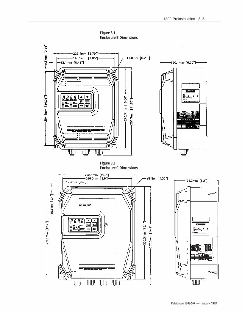
Figures 3.1 and 3.2 provide drive dimensions for enclosures B and Cas an aid in calculating the total area required by the 1302 Drives.Appendix A lists drive weights.
Site Requirements
3–31302 Preinstallation
Publication 1302-5.0 — January, 1998
Figure 3.1Enclosure B Dimensions
Figure 3.2Enclosure C Dimensions
3–4 1302 Preinstallation
Publication 1302-5.0 — January, 1998
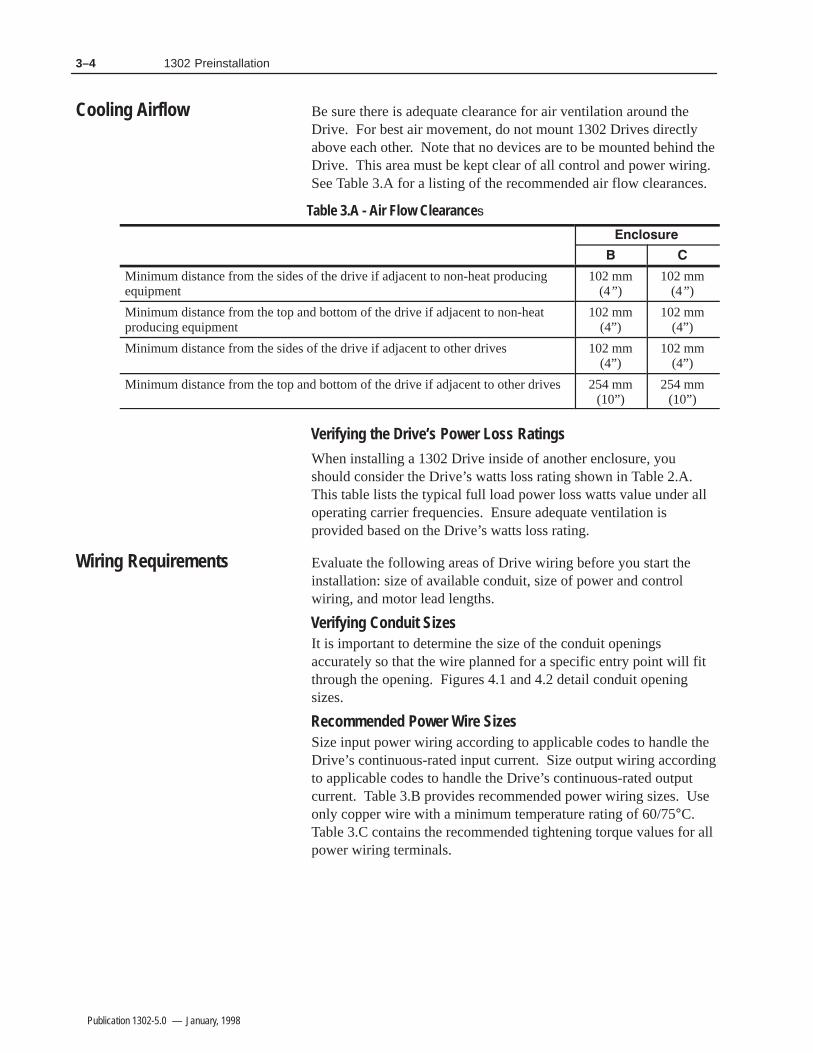
Be sure there is adequate clearance for air ventilation around theDrive. For best air movement, do not mount 1302 Drives directlyabove each other. Note that no devices are to be mounted behind theDrive. This area must be kept clear of all control and power wiring.See Table 3.A for a listing of the recommended air flow clearances.
Table 3.A - Air Flow Clearance
Minimum distance from the sides of the drive if adjacent to non-heat producingequipment
102 mm(4” )
102 mm(4” )
Minimum distance from the top and bottom of the drive if adjacent to non-heatproducing equipment
102 mm(4”)
102 mm(4”)
Minimum distance from the sides of the drive if adjacent to other drives 102 mm(4”)
102 mm(4”)
Minimum distance from the top and bottom of the drive if adjacent to other drives254 mm(10”)
254 mm(10”)
Verifying the Drive’s Power Loss Ratings
When installing a 1302 Drive inside of another enclosure, youshould consider the Drive’s watts loss rating shown in Table 2.A.This table lists the typical full load power loss watts value under alloperating carrier frequencies. Ensure adequate ventilation isprovided based on the Drive’s watts loss rating.
Evaluate the following areas of Drive wiring before you start theinstallation: size of available conduit, size of power and controlwiring, and motor lead lengths.
Verifying Conduit SizesIt is important to determine the size of the conduit openingsaccurately so that the wire planned for a specific entry point will fitthrough the opening. Figures 4.1 and 4.2 detail conduit openingsizes.
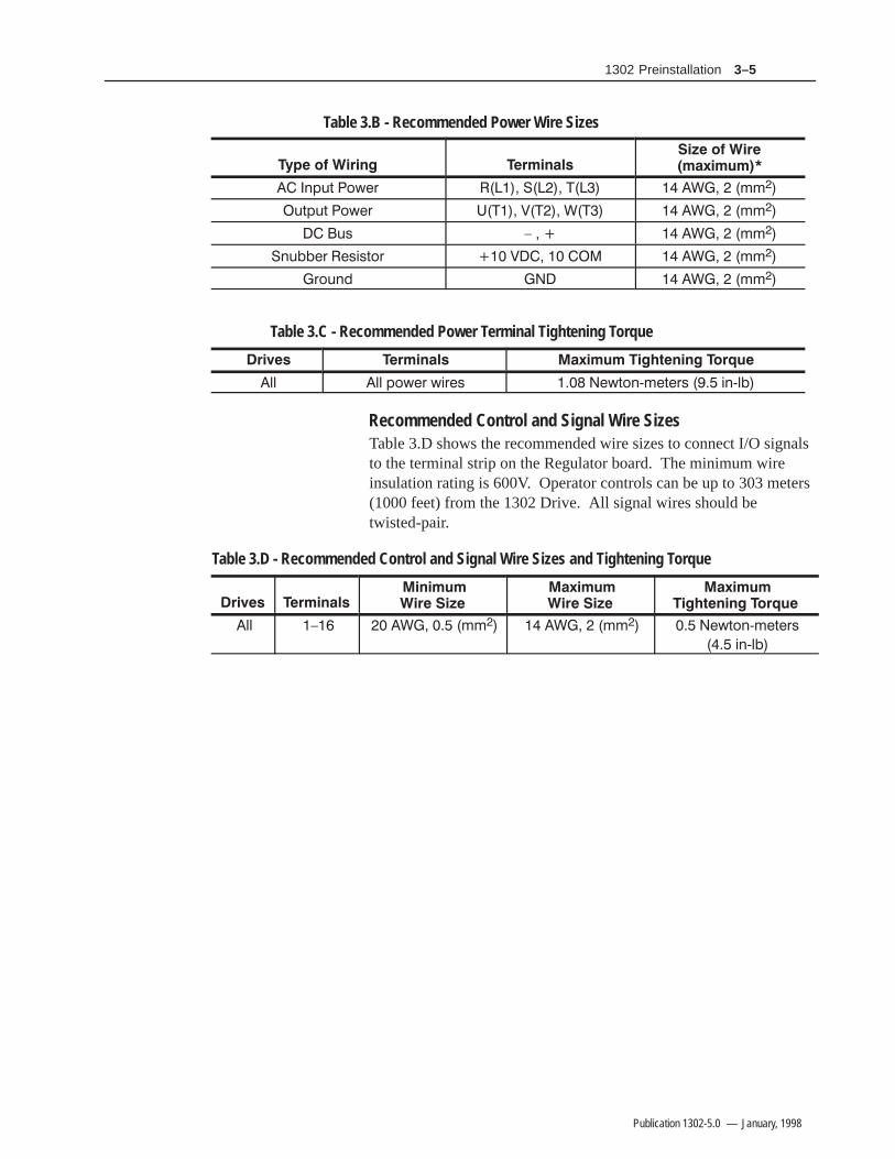
Recommended Power Wire SizesSize input power wiring according to applicable codes to handle theDrive’s continuous-rated input current. Size output wiring accordingto applicable codes to handle the Drive’s continuous-rated outputcurrent. Table 3.B provides recommended power wiring sizes. Useonly copper wire with a minimum temperature rating of 60/75°C.Table 3.C contains the recommended tightening torque values for allpower wiring terminals.
Cooling Airflow
Wiring Requirements
3–51302 Preinstallation
Publication 1302-5.0 — January, 1998
Table 3.B - Recommended Power Wire Sizes
')-, (.#* &&
-,)-, (.#* &&
-+ 0 &&
'-!!#* #+$+,(* &&
*(-'" &&
Table 3.C - Recommended Power Terminal Tightening Torque
%% %% )(.#* .$*#+ #.,('/&#,#*+ $'/%!
Recommended Control and Signal Wire SizesTable 3.D shows the recommended wire sizes to connect I/O signalsto the terminal strip on the Regulator board. The minimum wireinsulation rating is 600V. Operator controls can be up to 303 meters(1000 feet) from the 1302 Drive. All signal wires should betwisted-pair.
Table 3.D - Recommended Control and Signal Wire Sizes and Tightening Torque
%% 0 && && #.,('/&#,#*+
$'/%!

3–6 1302 Preinstallation
Publication 1302-5.0 — January, 1998
Recommended Motor Lead Lengths
The following motor lead lengths are recommended to reduce linedisturbances and noise. See Figure 3.3.
• For applications using one motor, motor lead length should not exceed 76 meters (250 feet).
• For applications with multiple motors, total motor lead length shouldnot exceed 76 meters (250 feet).
When total lead length exceeds 76 meters (250 feet), nuisance trips canoccur, caused by capacitive current flow to ground. Note that thesecapacitively-coupled currents should be taken into consideration whenworking in areas where drives are running. If the motor lead lengthmust exceed these limits, the addition of output line reactors or othersteps must be taken to correct the problem. See Table 3.E. Note thatthe motor lead lengths shown in Table 3.E are only guidelines. Yourapplication may be restricted to a shorter motor lead length due to:
• The type of wire
• The placement of the wire (for example, in conduit or a cable tray)
• The type of line reactor (For example, with or without LC filters)
• The type of motor
Figure 3.3How to Measure Motor Lead Lengths
!

3–71302 Preinstallation
Publication 1302-5.0 — January, 1998
Table 3.EMaximum Motor Cable Length Restrictions in meters (Feet) for 1302
No External Devices w/ 1204–TFA1 Terminator
Motor
1329R B 1329R A B
AnyCable
AnyCable
AnyCable
AnyCable
AnyCable
AnyCable
0.75 (1) 0.75 (1) NR NR
121.9(400)
152.4(500)
1.5 (2) 1.5 (2) NR NR
NR 121.9(400)
152.4(500)
2.2 (3) 2.2 (3) NR NR
NR 152.4(500)
304.8(1000)
152.4(500)
3.7 (5) 3.7 (5) NR
NR
304.8(1000)
5.6 (7.5) 5.6 (7.5) NR NR
NR NR NR
7.5 (10) 7.5 (10) NR NR
NR NR NR
Type A Motor Characteristics: No phase paper or misplaced phase paper, lower quality insulation systems, corona inception voltages between 850 and 1000 volts
Type B Motor Characteristics : Properly placed phase paper, medium quality insulation systems, corona inception voltages between 1000 and 1200 volts.
1329R Motors These AC Variable Speed motors are “Power Matched” for use with Allen–Bradley Drives. Each motoris energy efficient and designed to meet or exceed the requirements of the Federal Energy Act of 1992.All 1329R motors are optimized for variable speed operation and include premium inverter grade insulation systems which meet or exceed NEMA MG1. Part 31.40.4.2 1329R motors at 575V are rated 1850V insulation value.
Recommended MTE Reactor and LC Filter:1 hp at 4kHz use MTE part number: RL– 00803C1 hp at 6/8kHz use MTE part number RL– 00202C2/3/5 hp use MTE part number RL– 00803C7.5 hp use MTE part number RL– 01803C10 hp use MTE part number RL– 01803C
!ATTENTION: The 1302 AC Drive does not provideinput power short circuit fusing. Specifications for therecommended fuse size and type to provide Drive inputpower protection against short circuits are provided inTable 3.F. Branch circuit breakers or disconnectswitches cannot provide this level of protection forDrive components.
Input line branch circuit protection fuses must be used to protect theinput power lines. See Figure 5.A. Table 3.F shows recommendedfuse values. These fuse ratings are applicable for one Drive per branchcircuit. No other load may be applied to that fused circuit. Note thatcontactors and circuit breakers are not recommended for AC input linebranch protection.
Input Fusing

3–8 1302 Preinstallation
Publication 1302-5.0 — January, 1998
Table 3.F- AC Input Line Fuse Selection Values
ModelNumber
FuseRating*
1302–C001–AA 4A
1302–C001–AF 4A
1302–C002–AA 7A
1302–C002–AF 7A
1302–C003–AA 10A
1302–C003–AF 10A
1302–C004–AA 15A
1302–C005–AA 15A
1302–C005–AF 20A
1302–C007–AF 20A
1302–C010–AA 25A
1302–C010–AF 25A
!ATTENTION: The 1302 Drive control circuitryincludes solid state components. If hazards due toaccidental contact with moving machinery orunintentional flow of liquid, gas or solids exist, anadditional hardwired stop circuit is required to removeAC line power to the Drive. When AC input power isremoved, there will be a loss of inherent regenerativebraking effect and the motor will coast to a stop. Anauxiliary braking method may be required.
Depending upon the requirements of the application, the 1302 Drivecan be programmed to provide either a coast-to-rest (default) or aramp-to-rest (user-option) operational stop without physical separationof the power source from the motor. Refer to Chapters 5 and 8(parameter F-16) for more information on how to program anoperational stop.
In addition to the operational stop, users must provide a hardwiredemergency stop external to the Drive. The emergency stop circuit mustcontain only hardwired electromechanical components. Operation ofthe emergency stop must not depend on electronic logic (hardware orsoftware) or on the communication of commands over an electronicnetwork or link.
Complying with Machinery Safety Standard EN 6024–1:1992This section applies to users who must comply with machinery safetystandard EN 60204-1:1992, part 9.2.5.4, Emergency Stop.The 1302 Drive coast-to-rest stop is a category 0 operational stop. Theramp-to-rest stop is a category 1 operational stop.
Emergency Stop Installation

3–91302 Preinstallation
Publication 1302-5.0 — January, 1998
The required external hardwired emergency stop must be either acategory 0 or 1 stop, depending on the user’s risk assessment of theassociated machinery. In order to fully comply with machinerysafety standard EN 60204-1:1992, part 9.2.5.4, at least one of thetwo stop methods must be a category 0 stop.
To obtain motor nameplate horsepower, the Drive’s output currentrating at the selected carrier frequency should be equal to or greaterthan motor nameplate current. If the motor nameplate current ratingis higher than the Drive’s output current rating, derate motorhorsepower by the ratio of the Drive’s output ampere rating (at theselected carrier frequency) to the motor nameplate current. Note thatthis approximation is only accurate if the Drive and the motor havenearly the same rating.
Single Motor ApplicationsSize the drive and motor for the load and speed requirements of thespecific application.The motor’s operating current must not exceed the drive’s ratedoutput current (at the selected carrier frequency). In addition, themotor’s horsepower rating (for example, 1, 2, 3, 5, 7, 10 HP) mustnot be more than one horsepower range larger than the Drive’shorsepower rating.If the motor will be operated below one-half of its rated speed, themotor overload relay may not protect the motor because of reducedcooling action due to the reduced speed. A motor thermostat,internal to the motor, should be installed to monitor the actualtemperature of the windings.
Multiple – Motor ApplicationsOne Drive can run two or more motors. Adhere to the followingrequirements to assure correct Drive operation in this case:
• When starting and stopping all the motors at the same time (using the Drive for starting and stopping), the sum of the full-load sine wave currents of all the motors must be equal to or less than the maximum sine wave output current at the selected carrier frequency for the Drive.
! &
#! #! #! #
! !# !% $#$# # # "# !!! ! $'
• When one or more of the motors connected to the output of the Drive are to start independently (using a secondary switching device to add or remove the motor from the circuit):
Any motor that starts or stops while the Drive is running must have a current rating less than 10% of the maximum sine wave current rating of the Drive at the selected carrier frequency.
Motor Considerations

3–10 1302 Preinstallation
Publication 1302-5.0 — January, 1998
The sum of the maximum full-load sine wave currents of all the motors connected continuously to the Drive must be less than the maximum output current rating under all conditions.
Note that each motor requires separate thermal overload protection(for example, a motor relay or a motor thermostat).
Chapter 44–1
Publication 1302-5.0 — January, 1998
Installation
This chapter shows how to mount the 1302 Drive and its externalcomponents. Also shown are the entry areas for routing wiring inand out of the Drive.
Attach the drive to the selected flat, vertical surface using themounting holes provided. Enclosure B and C Drives have fourmounting holes. In order to maintain a flat mounting surface and toensure that bolt tightness is maintained, use washers under the boltheads. Refer to Figures 3.1 and 3.2 for Drive mounting dimensions.Use the following user-supplied mounting bolts and washers:
• Enclosure B Drives: four M8 (5/16”)• Enclosure C Drives: four M8 (5/16”)
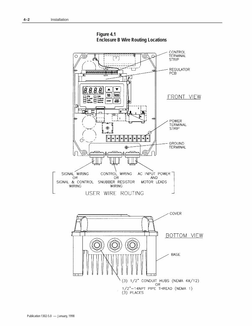
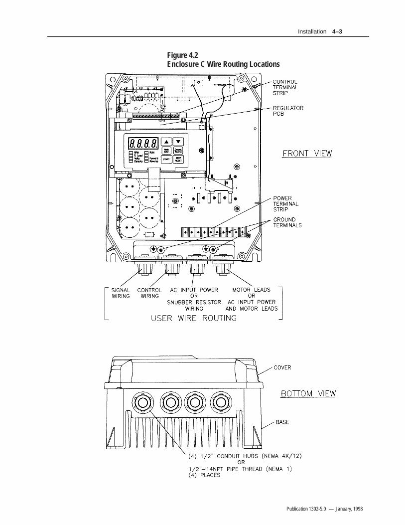
All wiring should be installed in conformance with the applicablelocal, national, and international codes (e.g., NEC/CEC). Signalwiring, control wiring, and power wiring must be routed in separateconduits to prevent interference with Drive operation. Do not routewires behind the Drive. Use grommets when hubs are not providedto guard against wire chafing. Figures 4.1 and 4.2 show the wirerouting, grounding terminal, and power terminal strips of the 1302Drives.
!ATTENTION: Do Not route signal and control wiringin the same conduit with power wiring. This can causeinterference with Drive operation. Failure to observethis precaution could result in damage to, ordestruction of, the equipment.
Do not route more than three sets of motor leads through a singleconduit. This will minimize cross-talk that could reduce theeffectiveness of noise reduction methods. If more than threeDrive/motor connections per conduit are required, you must useshielded cable. If possible, each conduit should contain only one setof motor leads.
!ATTENTION: Unused wires in conduit must begrounded at both ends to avoid a possible shock hazardcaused by induced voltages. Also, if a Drive sharing aconduit is being serviced or installed, all Drives usingthis conduit should be disabled to eliminate thepossible shock hazard from cross–coupled motor leads.Failure to observe these precautions could result inbodily injury.
Introduction
Mounting the Drive
Routing Wires
4–2 Installation
Publication 1302-5.0 — January, 1998
Figure 4.1Enclosure B Wire Routing Locations
4–3Installation
Publication 1302-5.0 — January, 1998
Figure 4.2 Enclosure C Wire Routing Locations

4–4 Installation
Publication 1302-5.0 — January, 1998
Install the input power and output power components that are locatedoutside of the 1302 enclosure. See Figure 5.1. The followingsections describe disconnect, transformer, and AC line branchprotection installation
DisconnectsAn input disconnect (for example, a switch or circuit breaker) mustbe installed in the line before the Drive input terminals in accordancewith local, national, and international codes (e.g., NEC/CEC). Sizethe disconnect according to the inrush current as well as anyadditional loads the disconnect might supply. Coordinate the triprating for the current (10 to 12 times the full load current) with thatof the input isolation transformer, if used. Refer to the Transformerssection of this chapter for additional information.
Input AC Line Branch Protection
!ATTENTION: Most codes require that upstreambranch protection be provided to protect input powerwiring. To guard against personal injury and/orequipment damage caused by improper fusing, useonly properly rated line fuses. Branch circuit breakersor disconnect switches cannot provide this level ofprotection for Drive components.
User-supplied branch circuit protection fuses must be installedaccording to the applicable local, national, and international codes(for example, NEC/CEC). The fuses must be installed in the linebefore the Drive’s AC input terminals. Table 3.F provides fusevalues.
Transformers
!ATTENTION: If the AC input power system does nothave a neutral or one phase referenced to ground, anisolation transformer with the neutral of the secondarygrounded is highly recommended. If the line–to–linevoltages on any phase can exceed 125% of the nominalline–to–line voltage, an isolation transformer with theneutral of the secondary grounded, is always required.Failure to observe these precautions could result inbodily injury or damage to equipment.
ATTENTION: When the AC line is shared directlywith other SCR–rectified drives, an optional snubberresistor braking kit might be required to alleviateexcess DC bus voltage. Failure to observe theseprecautions could result in damage to, or destructionof, the equipment.
External ComponentInstallation

4–5Installation
Publication 1302-5.0 — January, 1998
Input isolation transformers may be needed to help eliminate thefollowing:
• Damaging line voltage transients.• Line noise from the Drive back to the incoming power source.• Damaging currents that could develop if a point inside the Drive
becomes grounded.
Observe the following guidelines when installing an isolation transformer:
• A power disconnecting device must be installed between the power line and the primary of the transformer. If the power disconnecting device is a circuit breaker, the circuit breaker trip rating must be coordinated with the inrush current (10 to 12 times the full load current) of the transformer.
• Do NOT use an input isolation transformer rated more than 100 KVA for 230 VAC (or 1000 KVA for 460 VAC) with less than 5% impedance directly ahead of the Drive without additional impedance between the Drive and the transformer.
If your 1302 application requires the use of an output transformer,contact Allen–Bradley for assistance.
Output Contactors
!ATTENTION: Any disconnecting means wired todrive output terminals U,V, and W must be capable ofdisabling the Drive if opened during Drive operation.If opened during Drive operation, the Drive willcontinue to produce output voltage between U, V, andW. An auxiliary contact must be used tosimultaneously disable the Drive or output componentdamage may occur.
Output contactors provide a positive means of disconnecting themotor from the Drive. If your 1302 application requires the use ofoutput contactors, contact Allen–Bradley for assistance.
Mechanical Motor Overload ProtectionTo provide the motor with overload protection, local, national, andinternational codes (for example, NEC/CEC) require that a motorthermostat, internal to the motor, be installed or an electronic thermalmotor overload relay, sized to protect the motor, be installed betweenthe motor and the Drive’s output terminals.
The Electronic Thermal Overload parameter (F-14) may be used inplace of the electronic thermal motor overload relays in single motorapplications. Note, however, that temperature-sensing devicesintegral to the motor are the best way of thermally-protecting ACmotors under all conditions. Parameter F-14 must be enabled toprovide overload protection. Refer to Chapter 8 for the parameterdescription.

4–6 Installation
Publication 1302-5.0 — January, 1998
In multiple motor applications, each motor must have its ownuser-supplied overload protection.
1302 Drives have an analog speed reference input. This is ajumper-selectable 0 to 10 VDC or 0 to 20 mA input withprogrammable gain and offset adjustments (parameters F-11 andF-12). Jumper J6 on the Regulator board is set to match the type ofincoming analog signal, either voltage or current. See Figures 2.2,4.3, and 5.3. Refer to Chapter 5 for more information.
Figure 4.3Jumper J6 Settings for the Analog Input Speed Reference
!ATTENTION: Disconnect and lock out power to theDrive before setting Jumper J6. Failure to disconnectpower may result in death or serious injury. Verify busvoltage using the following procedure before touchingany components in the drive. Do not attempt to servicethe Drive until the bus voltage has discharged to zerovolts.
Use the following procedure to set jumper J6:
Step 1. Turn off and lock out input power. Wait five minutes
Step 2. Remove the cover from the Drive by unscrewing the four cover screws.
Step 3. Verify that the DC bus voltage is zero by following the procedure in Chapter 9 titled Verifying DC Bus Voltage.
Step 4. Locate jumper J6 on the Regulator board. Refer to Fig. 2.3
Step 5. Move the jumper to the desired setting as detailed in Fig. 4.3
Step 6. Re–attach the cover
Step 7. Re–apply input power
Step 8. Verify that parameters F–11 and F–12 are correctly set.
Note that if the setting of jumper J6 is changed, the regulatorsoftware will not automatically detect it. Verify that parameters F-11(gain) and F-12 (offset) are set correctly before starting the Drive.
Setting the Analog InputJumper on the RegulatorBoard

4–7Installation
Publication 1302-5.0 — January, 1998
Follow these guidelines when preparing to install the motor:
• Verify that the motor is the appropriate size to use with the Drive.
• Verify that the total motor lead length does not exceed the values given in Chapter 3.
• Follow the instructions in the motor instruction manual when installing the motor.
• Verify that the motor is properly aligned with the application’s machine to minimize unnecessary motor loading due to shaft misalignment.
• If the motor is accessible when it is running, install a protective guard around all exposed rotating parts.
Motor Preparation

4–8 Installation
Publication 1302-5.0 — January, 1998
This Page Intentionally Blank
Chapter 55–1
Publication 1302-5.0 — January, 1998
Drive Wiring
This chapter describes how to wire the 1302 Drive including: inputwiring, control and signal wiring, output wiring, and grounding.
Input Power WiringUse the following steps to connect AC input power to the Drive:
Step 1. Verify that the AC input power to the Drive corresponds to the drive’s nameplate voltage and frequency.
Step 2. Wire the AC input power leads by routing them according tothe type of enclosure. Sees Figures 4.1 and 4.2 and Table 3.B for recommended wire sizes.
!ATTENTION: Do Not route signal and control wiringwith power wiring in the same conduit. This can causeinterference with Drive operation. Failure to observethis precaution could result in erractic drive operationor damage to, or destruction of, the equipment.
Step 3. Connect the AC input power leads to terminals R,S,T on thepower terminal strip.
Step 4. Tighten terminals R and S (single–phase input) or terminals R,S,T (three–phase input) to the proper torque as shown in Table 3.D.
Introduction

5–2 Drive Wiring
Publication 1302-5.0 — January, 1998
Table 5.1Typical Electrical Connections
,
,
#%)($"(
$($& *&"$"+ %(!$#" ! "(&$#!*&"$ !' '
'&-)%%"!
#)"!'$##(
'&-)%%"!
)'
&!*

5–3Drive Wiring
Publication 1302-5.0 — January, 1998
The Terminal strip on the Regulator board provides terminals forconnecting signal (for example, external speed reference and analogoutput) and control (for example, stop, start, and function loss)wiring. See Figure 5.2. Terminals for the following wireconnections are provided:
• Terminals 1–3: analog speed reference connections• Terminals 4–5: analog output connections• Terminals 6–11: digital input connections• Terminals 12–13: snubber resistor connections• Terminals 14–16: output status connections
Table 5.2Typical Control Terminal Strip Connections
!
"
%$!%$
$!%$#
%"##$ ""
%$!%$$$%#(
# $" $
$%""$!"
# $"" %
$"%$!%$
$ !
$"$
#$
"'"&"#
%$ ##
%"##$ ""
(
( $$
( $$
Analog Speed Reference WiringAnalog speed reference input wiring connects to terminals 1 through3 on the Regulator board’s teminal strip. See Figure 5.3. Thisreference signal is jumper-selectable for either a 0 to 10 VDC or 0 to20 mA input. The setting of jumper J6 on the Regulator boarddetermines whether the input reference is a voltage or current signal.This reference signal can be provided by either a user-supplied 5Kohm potentiometer or an external 0-10 VDC/0-20 mA supply. SeeChapter 4 for more information.
Signal and Control Wiring

5–4 Drive Wiring
Publication 1302-5.0 — January, 1998
Table 5.3Analog Speed Reference Wiring Connections
Ω
"!%$ !###!
%!
%
"!%$ !
$#
!
Analog Output WiringAnalog output wiring connects to terminals 4 and 5 on the Regulatorboard’s terminal strip. See Figure 5.4. This is a scaled 0 to 10 VDCoutput signal that is proportional to either current speed, percent ofload, calculated output voltage, or percent of the selected referencevalue, whichever is selected through parameter F-29. This outputsignal is available during both local and remote operation.
Figure 5.4Analog Output Wiring Connections
"!%$ #!
Digital input wiring connects to terminals 6 through 11 on theRegulator board’s terminal strip. The Drive has a 24 VDC powersupply that provides the required voltage for control signals.Enabling or disabling a control signal requires that a contact (switch)be opened or closed.
Digital Input Wiring

5–5Drive Wiring
Publication 1302-5.0 — January, 1998
Start and Stop Control WiringStart and stop control wiring connects to terminals 6, 7, and 11. SeeFigures 5.5 and 5.6. Note that these start/stop wiring connections arenot to be used in multi-speed preset applications which are discussedin the following section.
Figure 5.5Two–Wire Start/Stop Sample Control Wiring
Figure 5.6Three–Wire Start/Stop Sample Control Wiring

5–6 Drive Wiring
Publication 1302-5.0 — January, 1998
Multi–Speed Preset WiringMulti-speed preset wiring connects to terminals 6 through 8, and 11.See Figure 5.7. When control type 3 is selected through parameterF-00, remote terminal strip control is enabled with multi-speedpresets. This mode of operation changes the functionality ofterminals 6 through 8 and may be used in place of 2- and 3-wirestart/stop wiring. See Figure 5.8.
When you enable multi-speed preset operation, the state of terminals7 and 8 determine the source of the speed reference:
$ ! &$# !" !#'&
'&*# $%& $ &$ *
'&*# $%& $ &$ *
'&*# $%& $ &$ *
Figure 5.7Multi–Speed Preset Sample Control Wiring
&$&&"#%&
'&*#$%&
)(
'!&"!"%%
'%&" $!&$"
'&*#$%&
&$&&"#%&
'&*#$%&
'&*#$%&
"$)$($%
'!&"!"%%
" "!

5–7Drive Wiring
Publication 1302-5.0 — January, 1998
Figure 5.8Terminal Usage During Multi–Speed Preset Operation
$"%$!%$
$ !
$"$
#$
"'"&"#
%$ ##
%"##$ "
"
$"%$!%$
$"$$ !#$
%$(!"#$
%$(!"#$
"'"&"#
%$ ##
%"##$ "
"
IET Reset Control Wiring
IET reset control wiring connects to terminals 8 and 11. See Figures5.5 and 5.6. Note that these reset wiring connections are not to beused in multi-speed preset applications. See Figures 5.7 and 5.8.
Forward/Reverse Control WiringForward/reverse control wiring connects to terminals 9 and 11. SeeFigures 5.5 through 5.7. Note that the setting of the forward/reverseswitch is ignored when parameter F-17 is equal to 1 (disable reverseoperation).
Function Loss Control WiringFunction loss control wiring connects to terminals 10 and 11. SeeFigures 5.5 through 5.7. Typically, a function loss input is amaintained, normally-closed pushbutton.
A signal must be present at terminal 10 for the Drive to run. Afactory-installed jumper connects terminals 10 and 11 whichprovides that signal. Remove this jumper if a function loss input, acoast-stop pushbutton, or another external interlock (for example, amotor thermostat) is used. Removing the jumper allows the Drive tostop when the contact is open.
5–8 Drive Wiring
Publication 1302-5.0 — January, 1998
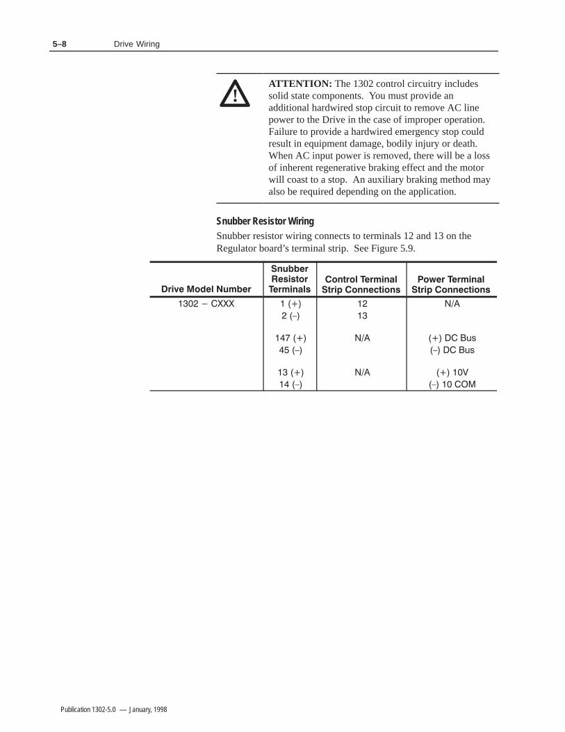
!ATTENTION: The 1302 control circuitry includessolid state components. You must provide anadditional hardwired stop circuit to remove AC linepower to the Drive in the case of improper operation.Failure to provide a hardwired emergency stop couldresult in equipment damage, bodily injury or death.When AC input power is removed, there will be a lossof inherent regenerative braking effect and the motorwill coast to a stop. An auxiliary braking method mayalso be required depending on the application.
Snubber Resistor WiringSnubber resistor wiring connects to terminals 12 and 13 on theRegulator board’s terminal strip. See Figure 5.9.

5–9Drive Wiring
Publication 1302-5.0 — January, 1998
Figure 5.9Snubber Resistor Wiring Connections for 1302 Drives
!
"
!
!
! !
! #
!
Output Status Relay WiringOutput status wiring connects to terminals 14 through 16 on theRegulator board’s terminal strip. See Figure 5.10. Parameter F-09specifies the type of status indication provided by the output relay.See the F-09 parameter description in Chapter 8 for moreinformation.
Figure 5.10Output Status Relay Wiring Connections
'
' !!%$&

5–10 Drive Wiring
Publication 1302-5.0 — January, 1998
Use the following steps to connect AC output power wiring from theDrive to the motor:
Step 1. Wire the AC output power leads by routing them according to the type of enclosure. See Figures 4.1 and 4.2. See Table 3.B for recommended wire sizes.
!ATTENTION: Do not route signal and control wiringin the same conduit with power wiring. This can causeinterference with Drive operation. Failure to observethis precaution could result in damage to, ordestruction of, the equipment.
Do not route more than three sets of motor leads through a single conduit. This will minimize cross-talk which could reduce the effectiveness of noise reduction methods. If more than three Drive/motor connections per conduit are required, you must use shielded cable. If possible, each conduit should contain only one set of motor leads.
!ATTENTION: Unused wires in conduit must begrounded at both ends to avoid a possilble shockhazard caused by induced voltages. If a Drive sharinga conduit is being serviced or installed, all Drives usingthis conduit should be disabled to eliminate thepossible shock hazard from cross coupled motor leads.Failure to observe these precautions could result inbodily injury.
Step 2. Connect the AC output power motor leads to terminals U, Vand W on the power terminal strip.
Step 3. Tighten terminals U, V, and W to the proper torque as shown in Table 3.D.
Use the following steps to ground the Drive:
!ATTENTION: You are responsible for conformingwith all applicable local, national and internationalcodes when grounding the Drive. Failure to observeprecautions and meet code could result in equipmentdamage or personal injury.
Step 1. Remove the Drive’s cover.
Step 2. Run a suitable equipment grounding conductor unbroken from the Drive’s ground terminal to the motor’s ground terminal and then to earth ground. Refer to Figures 4.1,4.2 and 5.1.
Step 3. Run a suitable grounding connector to the motor frame and transformer (if used).
Step 4. Re–attach the Drive’s cover
Output Power Wiring
Grounding
Chapter 66–1
Publication 1302-5.0 — January, 1998
Final Installation Checks
Chapter 6 provides a guide to help you run a final check of the 1302Drive installation.
!ATTENTION: Only qualified personnel familiar withthe 1302 Drive and associated machinery shouldperform troubleshooting or maintenance functions onthe Drive. Failure to comply may result in personalinjury and/or equipment damage.
Perform the following checks of the Drive installation with thepower off:
!ATTENTION: DC bus capacitors retain hazardousvoltage after input power has been disconnected.Disconnect and lock out power to the Drive and waitfive (5) minutes for the DC bus capacitors to discharge.Failure to disconnect power could result in death orserious injury. Verify bus voltages using the procedurein Chapter 9 before beginning any checks.
Step 1. Turn off, lock out, and tag the input power to the Drive. Wait 5 minutes.
Step 2. Check the DC bus potential with a voltmeter as described in Chapter 9 to ensure that the DC bus capacitors are discharged.
Step 3. If an input disconnect is installed, make sure it is in the OFFposition.
Step 4. Make certain that all Drive interlocks installed around the driven machine are operational.
!ATTENTION: You must provide an externalemergency stop circuit outside the Drive circuitry toremove AC line power to the Drive. This circuit mustdisable the system in case of improper operation.Failure to observe this precaution could result inequipment damage, bodily injury or death. When ACinput power is removed, there will be a loss of inherentregenerative braking effect and the motor will coast toa stop. An auxiliary braking method may be required.
Introduction
Power Off Checks
6–2 Final Installation Checks
Publication 1302-5.0 — January, 1998
Step 5. Verify that the user–installed stop pushbutton is wired correctly. Make certain the factory–installed jumper at terminals 10 and 11 has been removed so that the coast–stop pushbutton will work (Refer to Chapter 5).
!ATTENTION: Check that electrical commons are notintermixed in the Drive. Failure to observe thisprecaution could result in damage to, or destruction of,the Drive or process equipment.
Step 6. Remove any debris from around the Drive.
Step 7. Check that there is adequate clearance around the Drive.
Step 8. Verify that the wiring to the control terminal strip and power terminals is correct per Chapter 5.
Step 9. Check that the wire sizes are within terminal specifications and that the terminals are tightened to the appropriate torque specifications as specified in Chapter 3.
Step 10. Check that user supplied branch circuit protection is installed and correctly rated.
Step 11. Check that the incoming AC power is rated correctly.
Step 12. Check the motor installation and length of motor leads per the guidelines in Chapter 3.
Step 13. Disconnect any power correction capacitors connected between the Drive and the motor.
Step 14. Check that any motor thermal switch and the Drive’s electronic thermal overload are enabled (parameter F-15 = ON).
Step 15. Check that the rating of the transformer (if used) matches the Drive requirements and is connected for the proper voltage.
Step 16. Verify that a properly-sized ground wire is installed and thata suitable earth ground is used. Check for and eliminate any grounds between the motor frame and the motor power leads. Verify that all ground leads are unbroken.
Step 17. Uncouple the motor from any driven machinery to initially start the Drive.
6–3Final Installation Checks
Publication 1302-5.0 — January, 1998
Use the following procedure to check the operation of the Drive:
!ATTENTION: DC bus capacitors retain hazardousvoltage after input power has been disconnected.Disconnect and lock out power to the Drive and waitfive (5) minutes for the DC bus capacitors to discharge.Failure to disconnect power could result in death orserious injury. Verify bus voltages using the procedurein Chapter 9 before beginning any checks.
Step 1. Turn off, lock out, and tag the input power to the Drive. Wait 5 minutes.
Step 2. Remove the cover and check the DC bus potential with a voltmeter as described in Chapter 9. Verify that the DC bus capacitors are discharged. Replace the cover.
Step 3. Uncouple the driven equipment from the motor, if possible.
Step 4. Apply power to the Drive. SELF should be displayed for approximately 1 to 2 seconds to indicate internal diagnostics are being performed. After 1 to 2 seconds, 0 should be displayed and the LEDs should indicate Drive status. If any fault codes are displayed, refer to Chapter 9, Troubleshooting Reference.
Step 5. Check all parameter settings and verify that they are set correctly based on the application. In most cases, the factory default values are adequate for this no-load start-up test. Parameters are described in Chapter 8.
Step 6. Press the
key. The Drive should ramp at the acceleration rate (F-01) until it reaches the preset minimum speed (F-03).
Step 7. Verify the direction of the motor shaft rotation. If it is incorrect for your application, use the following procedure tochange the direction of rotation. If it is correct, go to step 8.
Step A.Press the
key to stop the Drive.
Step B. Wait until the motor has completely stopped.
Step C. Turn off, lock out, and tag power to the Drive. Wait five minutes.
Step D. Remove the cover and check the DC bus potential with a voltmeter as described in Chapter 9. Verify that the DC bus capacitors are discharged. Replace the cover.
Operational Checks
6–4 Final Installation Checks
Publication 1302-5.0 — January, 1998
Step E. Reverse any two of the three motor power leads (U, V, or W).
Step F. Turn the power on.
Step G. Press the
key and verify the direction of rotation.
Step 8. Using the and keys, run the motor without any load across the speed range. If the motor does not operate satisfactorily, check the parameter settings. Refer to Chapter 8.
Step 9. Press the
key to stop the Drive.
Step 10. Turn off, lock out, and tag power to the Drive. Wait five minutes. Remove the cover and check the DC bus potentialwith a voltmeter as described in Chapter 9. Verify that the DC bus capacitors are discharged. Replace the cover.
Step 11. Couple the driven equipment to the motor.
Step 12. Turn power on.
Step 13. Press the
key.
Step 14. Run the Drive across the required speed range under load. If the motor does not rotate at minimum speed, increase the manual torque boost (F-06).
Step 15. If the Drive operates the motor properly, go to step 16.
Step A. Refer to Chapter 9, Troubleshooting Reference, if any fault codes were displayed during start up.
Step B. Verify the parameter settings again.
Step 16. If the Drive operates the motor properly:
Step A.Press the
key to stop the Drive.
Step B. Record the parameter settings in Appendix B.
Chapter 77–1
Publication 1302-5.0 — January, 1998
Display and Keypad Operation
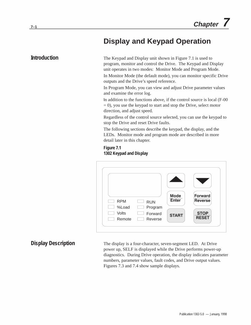
The Keypad and Display unit shown in Figure 7.1 is used toprogram, monitor and control the Drive. The Keypad and Displayunit operates in two modes: Monitor Mode and Program Mode.
In Monitor Mode (the default mode), you can monitor specific Driveoutputs and the Drive’s speed reference.
In Program Mode, you can view and adjust Drive parameter valuesand examine the error log.
n addition to the functions above, if the control source is local (F-00= 0), you use the keypad to start and stop the Drive, select motordirection, and adjust speed.
Regardless of the control source selected, you can use the keypad tostop the Drive and reset Drive faults.
The following sections describe the keypad, the display, and theLEDs. Monitor mode and program mode are described in moredetail later in this chapter.
Figure 7.11302 Keypad and Display
RPM%LoadVoltsRemote
RUNProgram
ForwardReverse
The display is a four-character, seven-segment LED. At Drivepower up, SELF is displayed while the Drive performs power-updiagnostics. During Drive operation, the display indicates parameternumbers, parameter values, fault codes, and Drive output values.Figures 7.3 and 7.4 show sample displays.
Introduction
Display Description

7–2 Display and Keypad Operation
Publication 1302-5.0 — January, 1998
The keypad’s six membrane keys are used to monitor, program, andcontrol the Drive. Table 7.A describes the keys.
Table 7.A - Key Descriptions
- .# ( ,,)1 % 3- .)
. * .#,)/"# .# ,$0 *,' . ,- ( ,,), &)" 1# ( .# ,$0 $- $( *,)",'')
(, - ), , - *,' . ,- (/' ,$ 0&/ ), -../- $( *,)",' ')
(, - ), , - .# $(. ,(& -* , ! , ( 1# ( 4 )(.,)& )/, & . ),
)& )1( .# - % 3- .) $(, - .# -,)&& -*
ModeEnter
- .# % 3 .)
0( .#,)/"# # ')($.), $-*&3 $. ' $( ')($.), ')
& . *,)",' ') 1# ( .# ,$0 $- -.)**
$-*&3 *,' . , 0&/ $( *,)",' ')
0 *,' . , 0&/ $( *,)",' ')
# % 3 *,)0$ - .# - !/(.$)(- , ",& -- )! .# )(.,)& -)/, - & . &)& ), , ').
ForwardReverse
- .# % 3 .) - & . .# $, .$)( )! ').), -#!. ,)..$)(1# ( .# )(.,)& -)/, $- &)& 4
START
- .# % 3 .) **&3 *)1 , .) .# ').), 1# ( .# )(.,)& -)/, $- &)&4
# ( .#$- % 3 $- *, -- ( .# , , () .$0 !/&.- .# ,$0 1$&& & ,. .).# &-. *,)",'' !, +/ (3 - .*)$(. -*
STOPRESET
- .# % 3 .)
/,( )!! .# ,$0 )/.*/. .) .# ').), $! .# ,$0 $- ,/(($("
& , ,$0 !/&.- 1# ( .# ,$0 $- $( *,)",' ')
2$. *,)",' ')
# ( .#$- % 3 $- *, -- .# ,$0 1$&& ,'* .) , -. . /- ,4 !$( ,. /- ,)*.$)( ), )-. .) , -. !/&. #$- % 3 -.)*- .# ,$0 , ",& -- )! .# - & . )(.,)& -)/, , '). ), &)&
Key Description

7–3Display and Keypad Operation
Publication 1302-5.0 — January, 1998
The keypad area contains eight LEDs that indicate either Drive statusor which Drive output value is displayed in monitor mode. Tables7.B and 7.C describe the Drive status LEDs and monitor modeLEDs, respectively.
Table 7.B - Drive Status LED Descriptions
Run On
Off
The Drive is generating an output voltage and frequency.
The drive is not generating an output voltage and frequency.
!ATTENTION: DO NOT use the RUN LED as anindication that no line voltage is present in the Drive.Verify there is no voltage present at the DC bus terminals(+) and (–) before servicing the Drive. Failure to observethis precaution could result in severe bodily injury or lossof life.
Program On
Off
The keypad and display are in program mode.
The keypad and display are in monitor mode.
Forward On
Off
The requested motor rotation direction is forward.
The requested motor rotation direction is not forward.
Reverse On
Off
The requested motor rotation direction is reverse.
The requested motor rotation direction is not reverse.
Remote On
Off
The Drive is being controlled from the terminal strip.
The Drive is being controlled from the keypad.
LED Descriptions

7–4 Display and Keypad Operation
Publication 1302-5.0 — January, 1998
Table 7.C - Monitor Mode LED Descriptions
# #& # # ( $($& '% # $& # )'&,'% # #& # )# ( & ($ (, %&"(& '& %( $# $& "$& #$&"( $#
$ &#( $ & * )!! !$ "%' &( #
$!(' & * $)(%)( *$!( ($ ( "$($&
!! ' $ $!(' !) $ ( ( * '% &&# ' #! ' ($ $ ( ($(! '!&&# &# , ")'( '( ($ ($ '%!+ ( ' *!) & ($ (, %&"(& '& %( $# $& "$& #$&"( $#
Program mode allows you to display and modify Drive parametervalues when the Drive is stopped. The following can be displayed inprogram mode:
• Parameter numbers
• Parameter values
• Error log information
To enter program mode:
Step 1. Stop the Drive (if it is running) by pressing theSTOP
RESET key.
Step 2. Press theModeEnter key until the PROGRAM LED turns on.
Parameter F-00 will be displayed. Use the key or key toscroll through the parameter list. The error log follows parameterF-49 and precedes parameter F-00 as shown in Figure 7.2.
Program Mode
7–5Display and Keypad Operation
Publication 1302-5.0 — January, 1998
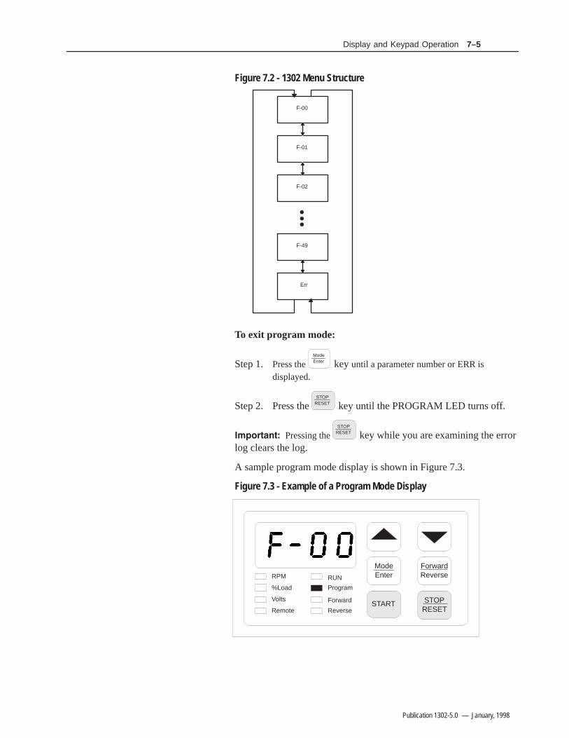
Figure 7.2 - 1302 Menu Structure
F-00
F-01
F-02
F-49
Err
To exit program mode:
Step 1. Press theModeEnter key until a parameter number or ERR is
displayed.
Step 2. Press the STOP
RESET key until the PROGRAM LED turns off.
Pressing theSTOP
RESET key while you are examining the errorlog clears the log.
A sample program mode display is shown in Figure 7.3.
Figure 7.3 - Example of a Program Mode Display
ModeEnter
START
ForwardReverse
STOPRESET
RPM
%Load
Volts
Remote
RUN
Program
Forward
Reverse

7–6 Display and Keypad Operation
Publication 1302-5.0 — January, 1998
For information about: Refer to chapter:
Displaying or changing parameter values 8
Ensuring program security 8
Individual parameters 8
Accessing the error log 9
Monitor mode is the keypad and display’s default mode of operation(in other words, the keypad and display will return to monitor modewhen you exit program mode). The keypad and display must be inmonitor mode before the Drive can be put into run (RUN LED is on)and will remain in monitor mode while the Drive is running.
The following output data can be displayed in monitor mode:
• RPM• % Load• Volts• Percent Selected Speed Reference (if F–13 = ON)
To select a value to monitor, press theModeEnter key until the LED turns
on next to the desired display item. Pressing theModeEnter key will
advance you through each of the displays. (Note that all the LEDswill turn on to indicate the percent selected speed reference display ifparameter F-13 is set to ON. Refer to the scaling the rpm section ofthis Chapter.)
A sample monitor mode display is shown in Figure 7.4
Figure 7.4 - Example of a Monitor Mode Display
ModeEnter
START
ForwardReverse
STOPRESET
RPM
%Load
Volts
Remote
RUN
Program
Forward
Reverse
Monitor Mode
7–7Display and Keypad Operation
Publication 1302-5.0 — January, 1998
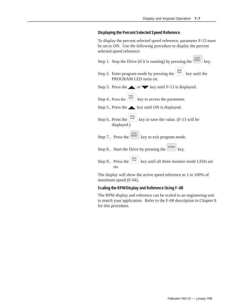
Displaying the Percent Selected Speed Reference
To display the percent selected speed reference, parameter F-13 mustbe set to ON. Use the following procedure to display the percentselected speed reference:
Step 1. Stop the Drive (if it is running) by pressing theSTOP
RESET key.
Step 2. Enter program mode by pressing the ModeEnter key until the
PROGRAM LED turns on.
Step 3. Press the or key until F-13 is displayed.
Step 4..Press theModeEnter key to access the parameter.
Step 5.. Press the key until ON is displayed.
Step 6.. Press the ModeEnter key to save the value. (F-13 will be
displayed.)
Step 7.. Press the STOP
RESET key to exit program mode.
Step 8.. Start the Drive by pressing the START
key.
Step 9.. Press the ModeEnter key until all three monitor mode LEDs are
on.
The display will show the active speed reference as 1 to 100% ofmaximum speed (F-04).
Scaling the RPM Display and Reference Using F–08
The RPM display and reference can be scaled to an engineering unitto match your application. Refer to the F-08 description in Chapter 8for this procedure.

7–8 Display and Keypad Operation
Publication 1302-5.0 — January, 1998
When the control source is the local keypad (F-00 = 0), the keypad isused to control the Drive. This means that the Drive will respond toSTART, STOP/RESET, and FORWARD/REVERSE commands onlyfrom the keypad. The functions of the keypad keys are described insection 7.2. Refer to the F-00 Control Source Select parameterdescription in Chapter 8 for more information on selecting a Drivecontrol source.
Changing the Reference Using the Keypadhe speed reference can be increased or decreased using the or
key when F-00 = 0 or 2. The display will show the internalspeed reference in hertz (Hz) while the keys are pressed. There willbe a slight delay before the display returns to the active monitormode.
Note that changing the drive’s internal speed reference using the or key when the Drive is under remote control will have no
operational effect on the Drive (unless F-00 = 2)
Drive Control
Chapter 88–1
Publication 1302-5.0 — January, 1998
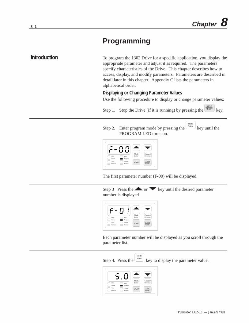
Programming
To program the 1302 Drive for a specific application, you display theappropriate parameter and adjust it as required. The parametersspecify characteristics of the Drive. This chapter describes how toaccess, display, and modify parameters. Parameters are described indetail later in this chapter. Appendix C lists the parameters inalphabetical order.
Displaying or Changing Parameter ValuesUse the following procedure to display or change parameter values:
Step 1. Stop the Drive (if it is running) by pressing theSTOP
RESET key.
Step 2. Enter program mode by pressing theModeEnter
key until the PROGRAM LED turns on.
ModeEnter
START
ForwardReverse
STOPRESET
RPM
%Load
Volts
Remote
RUN
Program
Forward
Reverse
The first parameter number (F-00) will be displayed.
Step 3 Press the or key until the desired parameternumber is displayed.
ModeEnter
START
ForwardReverse
STOPRESET
RPM
%Load
Volts
Remote
RUN
Program
Forward
Reverse
Each parameter number will be displayed as you scroll through theparameter list.
Step 4. Press the ModeEnter
key to display the parameter value.
ModeEnter
START
ForwardReverse
STOPRESET
RPM
%Load
Volts
Remote
RUN
Program
Forward
Reverse
Introduction

8–2 Programming
Publication 1302-5.0 — January, 1998
Step 5 .Press the or key to change the value.
ModeEnter
START
ForwardReverse
STOPRESET
RPM
%Load
Volts
Remote
RUN
Program
Forward
Reverse
Note that if programming has been disabled in parameter F-20(Password Lockout Enable), the value will not change. Refer toChapter 8, Ensuring Program Security, for more information.
Step 6.Press theModeEnter
key to save the changed value.
ModeEnter
START
ForwardReverse
STOPRESET
RPM
%Load
Volts
Remote
RUN
Program
Forward
Reverse
The parameter number is displayed again.
To display or change additional parameters, repeat steps 3through 6.
To exit program mode, press the ModeEnter key until a parameter
number or ERR is displayed; then press the STOP
RESET key.
Important: Parameter values and the keypad status (local orremote) are retained through a line dip or power loss.
!ATTENTION: It is your responsibility to determine howto distribute the password. Allen–Bradley is notresponsible for unauthorized access violations within theuser’s organization. Failure to observe this precautioncould result in equipment damage or bodily injury.
Parameter values can be password-protected using parameter F-20(Password Lockout Enable). When F-20 is set to ON, parametervalues can be displayed but cannot be modified from the keypadunless the correct password is entered in F-20.
Note: The password is factory set to 257 and cannot be modified bythe user.
Program Security

8–3Programming
Publication 1302-5.0 — January, 1998
Use the following procedure to disable or enable parameterprogramming:
Step 1. In program mode, press the or key until F-20 is displayed.
ModeEnter
START
ForwardReverse
STOPRESET
RPM
%Load
Volts
Remote
RUN
Program
Forward
Reverse
Step 2. Press theModeEnter
key to access the parameter. ON or OFF is displayed to indicate whether the password lockout feature is currently enabled or disabled.
ModeEnter
START
ForwardReverse
STOPRESET
RPM
%Load
Volts
Remote
RUN
Program
Forward
Reverse
ModeEnter
START
ForwardReverse
STOPRESET
RPM
%Load
Volts
Remote
RUN
Program
Forward
Reverse
Programming Enabled Programming Disabled
Step 3. Press the key until the password number, 257, is displayed. (Holding down the key increases the scroll speed.)
ModeEnter
START
ForwardReverse
STOPRESET
RPM
%Load
Volts
Remote
RUN
Program
Forward
Reverse
Step 4. Press theModeEnter
key to save the password number.
ModeEnter
START
ForwardReverse
STOPRESET
RPM
%Load
Volts
Remote
RUN
Program
Forward
Reverse
ON or OFF is displayed to indicate the current state of the passwordlockout.
8–4 Programming
Publication 1302-5.0 — January, 1998
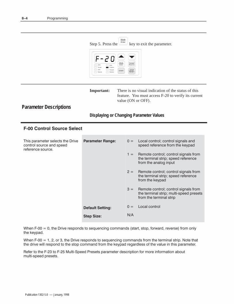
Step 5. Press theModeEnter
key to exit the parameter.
ModeEnter
START
ForwardReverse
STOPRESET
RPM
%Load
Volts
Remote
RUN
Program
Forward
Reverse
Important: There is no visual indication of the status of this feature. You must access F-20 to verify its current value (ON or OFF
Displaying or Changing Parameter Values
!* ')$+) *#+* + )!-&%+)&# *&,) % *'))% *&,)
&# &%+)&# &%+)&# *!%#* %*' ))% )&$ + "/'
$&+ &%+)&# &%+)&# *!%#* )&$+ +)$!%# *+)!' *' ))%)&$ + %#& !%',+
$&+ &%+)&# &%+)&# *!%#* )&$+ +)$!%# *+)!' *' ))%)&$ + "/'
$&+ &%+)&# &%+)&# *!%#* )&$+ +)$!%# *+)!' $,#+!0*' ')*+*)&$ + +)$!%# *+)!'
&# &%+)&#
% 0 + )!- )*'&%* +& *(,%!% &$$%* *+)+ *+&' &).) )-)* )&$ &%#/+ "/'
% 0 &) + )!- )*'&%* +& *(,%!% &$$%* )&$ + +)$!%# *+)!' &+ + ++ )!- .!## )*'&% +& + *+&' &$$% )&$ + "/' ))#** & + -#, !% + !* ')$+)
) +& + 0 +& 0 ,#+!0' )*+* ')$+) *)!'+!&% &) $&) !%&)$+!&% &,+$,#+!0*' ')*+*
Parameter Descriptions

8–5Programming
Publication 1302-5.0 — January, 1998
#
!* ')$+) *'!!* + $&,%+ & +!$ !+ +"* + $&+&)+& )$' )&$ *+&' +& + $/!$,$ *' *++!% !% 4
! "
+& *&%* *&%* *&%*
+ *+'&!%+ )(,%0 )(,*+ )&$ + "0' ,*!% + 33 %33 "0* !* #** + % + $/!$,$ *' *++!% + +!$ +& )$' +& + + )(,%0 .!## ')&'&)+!&%##0 #** + % + +,#)+ *++!% &) /$'# ! 4 21 % 4 *&%* !+ .!## +" *&%* +& )$' +& )(,%0 ))% & 1
&+ + + ! + #)+!&% )+ !* *+ +&& *+ % &-),))%+ ,#+ $0 &,) .!## !*'#0
#
!* ')$+) *'!!* + $&,%+ & +!$ !+ +"* + $&+&)+& )$' )&$ + $/!$,$*' *++!% !% 4 +& *+&'
! "
+& *&%* *&%* *&%*
+ )(,%0 )(,*+ )&$ + "0' ,*!% + 33 %33 "0* !* #** + % + $/!$,$*' *++!% + +!$ +& )$' +& + + )(,%0 .!## ')&'&)+!&%##0 #** + % + +,# )+ *++!%&) /$'# ! 4 21 % 4 *&%* !+ .!## +" *&%* +& )$' +& )(,%0))% & 21 )&$ 1
&+ + + ! + #)+!&% )+ !* *+ +&& *+ ! ,* ,#+ $0 &,) .!## !*'#0
# !
!* ')$+) #!$!+* + *'))% +& + )!-)#** & . + *'))% !* *,''#! + ),#+&) .!## %&+ &$$% *' #** + % + -#, !%4
! "
+& 1 1 1 ! 4 < 1 1 ! 4 ≥ 1
! )!- !* !%+% +& &')+ + $&+&) + ')+)$!%$!%!$,$ *' ,%#** !*&%%+ )&$ + '&.) *&,) ,*) !* )*'&%*!# &)**,)!% * &%!+!&%* &) &')+!% ')*&%%# 0 ')&-!!% *,!+# ,)* ,!# &)-!*,# #)$* &) &+ ) -!* +& !%!+ + + + )!- !* &')+!% + $!%!$,$ *''&**!#0 1)& *' &) + ,*) $,*+ -)!0 + + + $&+&) &,+',+ * + .!## )&++ + ##&$!%+!&%* & #& % &,+',+ *' )(,!) 0 + ''#!+!&%

8–6 Programming
Publication 1302-5.0 — January, 1998
# !
) &(#*( " # *) * )&(($ *% * ( ,(")) % -* )&(($ ) )+&&" *(+"*%( - "" $%* %##$ )& (*( *$ * ,"+ $1
"
*% 0 0 0 1 < 0 0 1 ≥ 0
! +)( ) ()&%$) " %( $)+( $ ** ( ,$ # $(/ "" ( ,1*( $#$ )#) $ &(%)) " $ #*( " ( &" % ) %&(* %$ * #. #+# )&1 "+( *% %)(, * ) &(+* %$ %+" ()+"* $ % "/ $!+(/ %( '+ &#$* #
#
) &(#*( " # *) #%*%(%+*&+* *%('+ - " * ) (+$$ $%( "(* $
"
*% % (* ( , +(($*
$ %+*&+* +(($* **#&*) *% . * &()* +(($* " # * #%*%( +(($* - "" # $* $ %((+ %( * "(* %$ "(* %$ * # - "" .*$ +(($* " # * ) )* *%% "%- %( *%% ("* , *% * ('+ ( "% $ %,(+(($* +"* #/ %+( - "" )&"/
8–7Programming
Publication 1302-5.0 — January, 1998
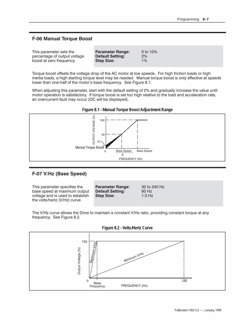
$ " " !
"./8 5'7'2+9+7 8+98 9.+5+7)+39'-+ 4, 4:95:9 ;419'-+(4489 '9 ?+74 ,7+6:+3)>
! "! !!! #
94
"476:+ (4489 4,,8+98 9.+ ;419'-+ *745 4, 9.+ 24947 '9 14< 85++*8 47 ./-. ,7/)9/43 14'*8 47 ./-./3+79/' 14'*8 ' ./-. 89'79/3- 9476:+ 1+;+1 2'> (+ 3++*+* '3:'1 9476:+ (4489 /8 431> +,,+)9/;+ '9 85++*814<+7 9.'3 43+@.'1, 4, 9.+ 249478 ('8+ ,7+6:+3)> !++ /-:7+
%.+3 '*0:89/3- 9./8 5'7'2+9+7 89'79 </9. 9.+ *+,':19 8+99/3- 4, '3* -7'*:'11> /3)7+'8+ 9.+ ;'1:+ :39/124947 45+7'9/43 /8 8'9/8,')947> , 9476:+ (4489 /8 8+9 944 ./-. 7+1'9/;+ 94 9.+ 14'* '3* '))+1+7'9/43 7'9+'3 4;+7):77+39 ,':19 2'> 4)):7 </11 (+ */851'>+*
Figure 8.1 - Manual Torque Boost Adjustment Range
'8+ !5++*'8+ !5++*
#& ?
Manual Torque Boost
#"#"$"
$ #
"./8 5'7'2+9+7 85+)/,/+8 9.+('8+ 85++* '9 2'=/2:2 4:95:9;419'-+ '3* /8 :8+* 94 +89'(1/8.9.+ ;4198.+79? $? ):7;+
! "! !!! #
94 ? ? ?
".+ $? ):7;+ '114<8 9.+ 7/;+ 94 2'/39'/3 ' )4389'39 $? 7'9/4 574;/*/3- )4389'39 9476:+ '9 '3>,7+6:+3)> !++ /-:7+
Figure 8.2 - Volts/Hertz Curve
#& ?
240
'8+7+6:+3)>
:95:9$419'-+
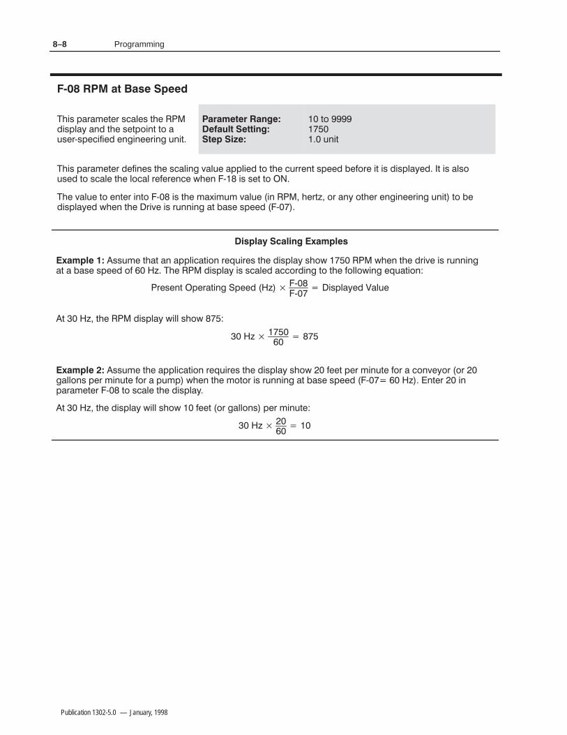
8–8 Programming
Publication 1302-5.0 — January, 1998
!
&'/ ,.)#0#. /!(#/ 0&# "'/,(5 *" 0&# /#0,+'*0 0+ 1/#.7/,#!'$'#" #*%'*##.'*% 1*'0
0+ 1*'0
&'/ ,.)#0#. "#$'*#/ 0&# /!('*% 2(1# ,,('#" 0+ 0&# !1..#*0 /,##" #$+.# '0 '/ "'/,(5#" 0 '/ (/+1/#" 0+ /!(# 0&# (+!( .#$#.#*!# 3&#* 7 '/ /#0 0+
&# 2(1# 0+ #*0#. '*0+ 7 '/ 0&# )4')1) 2(1# '* &#.06 +. *5 +0&#. #*%'*##.'*% 1*'0 0+ #"'/,(5#" 3&#* 0&# .'2# '/ .1**'*% 0 /# /,##" 7
//1)# 0&0 * ,,('!0'+* .#-1'.#/ 0&# "'/,(5 /&+3 3&#* 0&# ".'2# '/ .1**'*%0 /# /,##" +$ 6 &# "'/,(5 '/ /!(#" !!+."'*% 0+ 0&# $+((+3'*% #-10'+*
.#/#*0,#.0'*%,##"6 7 7
'/,(5#"(1#
0 6 0&# "'/,(5 3'(( /&+3
6
6
//1)# 0&# ,,('!0'+* .#-1'.#/ 0&# "'/,(5 /&+3 $##0 ,#. )'*10# $+. !+*2#5+. +. %((+*/ ,#. )'*10# $+. ,1), 3&#* 0&# )+0+. '/ .1**'*% 0 /# /,##" 7 6 *0#. '*,.)#0#. 7 0+ /!(# 0&# "'/,(5
0 6 0&# "'/,(5 3'(( /&+3 $##0 +. %((+*/ ,#. )'*10#
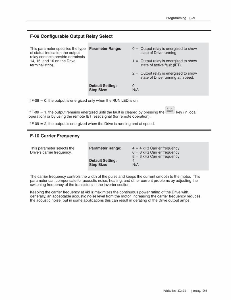
8–9Programming
Publication 1302-5.0 — January, 1998
&'1 .0+#2#0 1.#!'$'#1 2&# 27.#-$ 12231 ',"'!2'-, 2&# -32.320#*7 !-,2!21 .0-4'"# 2#0+',*1 ," -, 2&# 0'4#2#0+',* 120'.
32.32 0#*7 '1 #,#0%'8#" 2- 1&-5122# -$ 0'4# 03,,',%
32.32 0#*7 '1 #,#0%'8#" 2- 1&-5122# -$ !2'4# $3*2
32.32 0#*7 '1 #,#0%'8#" 2- 1&-5122# -$ 0'4# 03,,',% 2 1.##"
$ 9 2&# -32.32 '1 #,#0%'8#" -,*7 5&#, 2&# '1 -,
$ 9 2&# -32.32 0#+',1 #,#0%'8#" 3,2'* 2&# $3*2 '1 !*#0#" 7 .0#11',% 2&#STOP
RESET )#7 ', *-!*-.#02'-, -0 7 31',% 2&# 0#+-2# 0#1#2 1'%,* $-0 0#+-2# -.#02'-,
$ 9 2&# -32.32 '1 #,#0%'8#" 5&#, 2&# 0'4# '1 03,,',% ," 2 1.##"
&'1 .0+#2#0 1#*#!21 2�'4#1 !00'#0 $0#/3#,!7
)8 00'#0 $0#/3#,!7 )8 00'#0 $0#/3#,!7 )8 00'#0 $0#/3#,!7
&# !00'#0 $0#/3#,!7 !-,20-*1 2&# 5'"2& -$ 2&# .3*1# ," )##.1 2&# !300#,2 1+--2& 2- 2&# +-2-0 &'1.0+#2#0 !, !-+.#,12# $-0 !-312'! ,-'1# ',% ," -2� !300#,2 .0- *#+1 7 "(312',% 2'2!&',% $0#/3#,!7 -$ 2&# 20,1'12-01 ', 2&# ',4#02#0 1#!2'-,
##.',% 2&# !00'#0 $0#/3#,!7 2 )8 +6'+'8#1 2&# !-,2',3-31 .-5#0 02',% -$ 2&# 0'4# 5'2&%#,#0**7 , !!#.2 *# !-312'! ,-'1# *#4#* $0-+ 2&# +-2-0 ,!0#1',% 2&# !00'#0 $0#/3#,!7 0#"3!#12&# !-312'! ,-'1# 32 ', 1-+# ..*'!2'-,1 2&'1 !, 0#13*2 ', "#02',% -$ 2&# 0'4# -32.32 +.1
8–10 Programming
Publication 1302-5.0 — January, 1998
!"* ')$+) *#* +!$/"$,$ )$&+ *'))% +& $+! /+)%#(,"'$%+
+& & ,## *# $/"$,$))%
&)$##0 +! $/"$,$ *' ))% +! $&,%+ & ))% + $/"$,$ *' 1 "* "+!) &) $ ! ))% "% "* ,* +& *# +! *' ))% +& %&+!) -#, &) /$'# &) $ %+) +! ')$+) -#, "% ')%+ & ,## *# ))%
& #,#+ +! *# ))% " 0&, ) ,*"% ,* +! &##&."% (,+"&%
*")/"$,$)%$
)%% / "%$))%
+! )$&+ *' ))% "* +& $ % +! $/"$,$ ))% )(,") "* $ *# *&##&.*
/ "%
& #,#+ +! *# ))% " 0&, ) ,*"% ,* +! &##&."% (,+"&%
*")/"$,$)%
)%% / "%))%
+! )$&+ *' ))% "* +& % +! $/"$,$ ))% )(,") "* *# *&##&.*
/ "%

8–11Programming
Publication 1302-5.0 — January, 1998
!
&'0 -/*#1#/ 0!)#0 1&#/#*,1# 0-##" /#$#/#+!# 1, ,/ 1, * 1, *'+'*2* 3)2#
1, ,$ $2)) 0!)# *'+'*2* /#$#/#+!#
6-'!))6 1&# 3)2# ,$ 1&# *'+'*2* 0-##" /#$#/#+!# 1&# *,2+1 ,$ /#$#/#+!# 1 *'+'*2* 0-##" 7 '0#'1&#/ ,/ * +1#/ 1&# -/*#1#/ 3)2# 0 -#/!#+1%# ,$ 1&# $2)) 0!)# /#$#/#+!# 1, # ,$$0#1 $/,**'+'*2* 0-##"
, !)!2)1# 1&# 0!)#" *'+'*2* /#$#/#+!# 20# 1&# $,)),4'+% #.21',+
#0'/#"'+'*2*-##"$$0#1
#$#/#+!#+%# ,$$0#1
$ 1&# /#*,1# +),% '+-21 0-##" /#$#/#+!# '0 1, * 0#1 ,+ 1#/*'+)0 +" +"1&# 3') )# +),% /#$#/#+!# 0'%+) '0 1, * 20# 7 1, , 1'+ *'+'*2* 0-##" 4'1& *'+'*2*+),% '+-21 0 $,)),40
$ 1&# /#*,1# +),% '+-21 0-##" /#$#/#+!# '0 1, 0#1 ,+ 1#/*'+)0 +" +"1&# 3') )# 0'%+) '0 ,$$0#1 20# 7 1, , 1'+ *'+'*2* 0-##" 4'1& *'+'*2* +),% '+-21 0$,)),40
5,$$0#1
5,$$0#1
!
&'0 -/*#1#/ #+ )#0 ,/"'0 )#0 1&# $,2/1& *,+'1,/*,"# "'0-)6
,2/1& *,+'1,/ *,"# "'0-)6 '0#+ )#"
,2/1& *,+'1,/ *,"# "'0-)6 '0"'0 )#"
$ 7 1&# !2//#+1 3)2# ,$ 1&# !1'3# 0-##" /#$#/#+!# !+ # "'0-)6#" 6 -/#00'+% 1&#ModeEnter (#6
4&')# 1&# /'3# '0 /2++'+% 2+1') )) 1&/## *,+'1,/ *,"# 0 /# ,+ &# !1'3# 0-##" /#$#/#+!# '0"'0-)6#" 0 1, ,$ *5'*2* 0-##" 7
$ 7 1&# !1'3# 0-##" /#$#/#+!# 4')) +,1 # "'0-)6#"
#$#/ 1, &-1#/ $,/ *,/# '+$,/*1',+ ,+ 1&# *,+'1,/ *,"# "'0-)60

8–12 Programming
Publication 1302-5.0 — January, 1998
$ "
&'0 ./+#1#/ 0#10 1&# 1/'. *#3#*$-/ 1&# #*#!1/-,'! 1&#/+*-3#/*-" $2*1 4&#,7
! #
1- /1#" !2//#,1
&'0 ./+#1#/ 0&-2*" # "(201#" '$ 1&# +-1-/ !2//#,1 /1',% '0 *#00 1&, 1&# /'3# !2//#,1 /1',%
0# 1&# $-/+2* #*-4 1- !*!2*1# 1&# 0#11',% *#3#* 0 .#/!#,1%# -$ +5'+2+ !-,1',2-20 !2//#,1
7-1-/2**-"2//#,1
/'3#21.211#"2//#,15
&# +-1-/ $2** *-" !2//#,1 3*2# !, # $-2," -, 1&# +-1-/ ,+#.*1# ## *# -/ 1&# /'3#,+#.*1# $-/ 1&# /'3# /1#" -21.21 3*2#
$ "
&'0 ./+#1#/ #, *#0 -/"'0 *#0 1&# #*#!1/-,'! +-1-/1&#/+* -3#/*-" $2,!1'-, &'0$2,!1'-, -.#/1#0 *')# +-1-/1&#/+* 04'1!& 1- ./-1#!1 1&#+-1-/ $/-+ -3#/',%
! #
- #*#!1/-,'! 1&#/+* -3#/*-"./-1#!1'-,
*#!1/-,'! 1&#/+* -3#/*-"./-1#!1'-, '0 !1'3#
! /+#1#/ 7 +201 # 0#1 1- ', 0',%*# +-1-/ ..*'!1'-,0 1- %2/" %',01"+%# $/-+ -3#/',% -/ !-+ 201'-, -$ 02//-2,"',% +1#/'*0 '*2/# 1- - 0#/3# 1&'0./#!1'-, !-2*" /#02*1 ', $'/# -/ "+%# 1- -/ "#01/2!1'-, -$ 1&# +-1-/ ," 1&# "/'3#
&#, 7 1&# /'3# $2*10 '$ '1 #5!##"0 1&# 1&#/+* -3#/*-" 1'+# 0#!-,"0 1 -$ 7&#, , #51#/,* 1&#/+* 04'1!& -/ -1&#/ -3#/1#+.#/12/# +-,'1-/',% "#3'!# '0 !-,,#!1#" 1- 1&# $2,!1'-,*-00 !'/!2'1 1#/+',*0 ," 1&'0 ./+#1#/ +6 # 0#1 -/
-/ +2*1'7+-1-/ ..*'!1'-,0 0#1 1&'0 ./+#1#/ 1- &# ',"'3'"2* +-1-/0 +201 &3# 1&#/+* 04'1!&./-1#!1'-,

8–13Programming
Publication 1302-5.0 — January, 1998
#
* ')$+) *#+* &. +$&+&) . ## *+&' .% -% *+&' &$$%
"
%# &*+ *+&' $&+&) . ##&*+ +& )*+
*# &*+ *+&' $&+&) . ##)$' +& )*+
! &, $,*+ ')&- % /+)%# ). ) $)%0 *+&' ), + &,+* & +) - ), +)0 * ), + $,*+ *# + *0*+$ % * & $')&') &')+ &% %&%+)&##$ % &')+ &% $0 )*,#+ + * ')&,) * %&+ &##&. #,) +& &*)- + *'),+ &% &,# )*,#+ ) - &) (, '$%+ $ & #0 %!,)0 &) +
&*+1+&1)*+ *+&' +,)%* & + +)%* *+&) '&.) - ) -)* )$'1+&1)*+ *+&' )* + +)%* *+&)'&.) - ) -)* ,%+ # + $&+&) &$* +& *+&' % +% +,)%* & + '&.) - ) -)*
&+ ++ + ,%+ &% #&** %',+ &'% % &) ) - ,#+ . ## #.0* ,* &*+1+&1)*+ *+&'
# !
* ')$+) %#* &) *#* )-)* )&++ &% & +$&+&)
"
*# )-)* %# )-)*
1 + &).))-)* %',+ ##&.* &).) &) )-)* )&++ &% & + $&+&)
1 )-)* )&++ &% & + $&+&) * ')& + % 1 ')** % +ForwardReverse "0 &% +
"0' % #&# &%+)&# &) . ) % +& +)$ %# &% + +)$ %# *+) ' % )$&+ &%+)&# &* %&+ + ) -&')+ &%

8–14 Programming
Publication 1302-5.0 — January, 1998
$
)& 1"3".&5&3 &/"#-&4 5)&4&510*/5 50 #& %*41-":&% */ =6/*54
#
&510*/5 *4 %*41-":&% */ )&35;
&510*/5 *4 %*41-":&% */ 5)& 6/*5441&$*'*&% */ =
' = 13&44*/( 5)& "/% ,&:4 8*-- $)"/(& 5)& 4&510*/5 */ 6/*54 0' #&58&&/ .*/*.6.41&&% */ = 6/*54 "/% ."9*.6. 41&&% */ = 6/*54 05& 5)"5 5)*4 1"3".&5&3 0/-: "''&$54 5)& 4&510*/5 /055)& %*41-":
"
446.& " 3*7& *4 $633&/5-: 36//*/( "5 ; = "/% = !)&/ 5)&,&: *4 13&44&% *4 %*41-":&% !)&/ 5)& ,&: *4 13&44&% 5)3&& .03& 5*.&4 5)& %*41-": 8*-- $)"/(&'30. 50 50 50 )& 3&'&3&/$& *4 5)&/ 3&4$"-&% #"4&% 0/ 5)*4 */165
/1653&'&3&/$&&'&3&/$&
=< = ; ;
$ !$
)*4 1"3".&5&3 %&5&3.*/&48)&5)&3 5)& .0503 45"354"650."5*$"--: 8)&/ 5)& 3*7& *4108&3&% 61
#
0503 %0&4 /05 45"35 "5 3*7&108&3 61
0503 45"354 "5 3*7& 108&3 61
! &55*/( = $"64&4 065165 108&3 50 #& "11-*&% 50 5)& .0503 "650."5*$"--:"5 3*7& 108&3 61 !)&/ 5)*4 '6/$5*0/ *4 &/"#-&% :06 .645 &/463& 5)"5 "650."5*$ 45"35 61 0' 5)&%3*7&/ &26*1.&/5 8*-- /05 $"64& */+63: 50 01&3"5*/( 1&340//&- 03 %"."(& 50 5)& %3*7&/&26*1.&/5 / "%%*5*0/ :06 "3& 3&410/4*#-& '03 1307*%*/( 46*5"#-& "6%*#-& 03 7*46"- "-"3.4 0305)&3 %&7*$&4 50 */%*$"5& 5)"5 5)*4 '6/$5*0/ *4 &/"#-&% "/% 5)& 3*7& .": 45"35 "5 "/: .0.&/5 )*4 1"3".&5&3 .": 0/-: #& 64&% "4 065-*/&% */ 1"3"(3"1) &9$&15*0/4 '0341&$*"-*;&% "11-*$"5*0/4 26*1.&/5 %"."(& "/%03 1&340/"- */+63: .": 3&46-5 *' 5)*41"3".&5&3 *4 64&% */ "/ */"113013*"5& "11-*$"5*0/
!)&/ = 065165 108&3 *4 "11-*&% 50 5)& .0503 "5 %3*7& 108&3 61 *' 5)& '0--08*/( $0/%*5*0/4 "3& .&5
)& %3*7& 108&3=61 %*"(/045*$4 .645 #& 1"44&% 8*-- #& %*41-":&% "5 108&3 61
0 '"6-54 $"/ #& "$5*7&
)& 5&3.*/"- 453*1 '6/$5*0/ -044 */165 .645 #& $-04&%
)& '30/5=1"/&- ,&:1"%STOP
RESET ,&: .645 /05 #& 13&44&%
' 5)& 3*7& *4 6/%&3 -0$"- $0/530- *5 8*-- &''&$5*7&-: 4*.6-"5& " 45"35 4*(/"- 50 45"35 5)& 3*7&
' 5)& 3*7& *4 6/%&3 3&.05& $0/530- 5)& 3*7& 8*-- 45"35 0/-: *' 5)& 5&3.*/"- 453*1 */165 *4 "44&35&%
8–15Programming
Publication 1302-5.0 — January, 1998
) ""&! $#
'(2 / 1 ,$3$1 $- !+$2 .1#(2 !+$2 / 1 ,$3$1 / 226.1#/1.3$"3(.-
!#!
$# ### (
226.1# +."*.43 #(2 !+$#/ 1 ,$3$12 " - !$ ,.#(%($#
226.1# +."*.43 $- !+$#/ 1 ,$3$12 " --.3 !$ ,.#(%($#
! 3 (2 8.41 1$2/.-2(!(+(38 3. #$3$1,(-$ '.6 3. #(231(!43$ 3'$ / 226.1#++$-1 #+$8 (2 -.3 1$2/.-2(!+$ %.1 4- 43'.1(9$# ""$22 5(.+ 3(.-2 6(3'(- 3'$ 42$12.1& -(9 3(.- (+41$ 3. .!2$15$ 3'(2 /1$" 43(.- ".4+# 1$24+3 (- $04(/,$-3 # , &$ .1 !.#(+8(-)418
'$- : / 1 ,$3$1 5 +4$2 " - !$ #(2/+ 8$# !43 " --.3 !$ ,.#(%($# $7"$/3 : -3$1(-& 3'$% "3.18:2$3 / 226.1# -4,!$1 3.&&+$2 3'$ 23 3$ .% 3'$ +."*.43 $%$1 3. ' /3$1 -241(-& 1.&1 ,$"41(38 %.1 3'(2 /1."$#41$
!## '$1$ (2 -. 5(24 + (-#(" 3(.- .% 3'$ 23 342 .% 3'(2 %$ 341$ .4 ,423 ""$22 : 3. 5$1(%8 (32"411$-3 5 +4$ .1
) % ! $'
'(2 / 1 ,$3$1 2/$"(%($2 3'$,(#/.(-3 .% 3'$ 5.(# -"$ ! -#2$+$"3$# (- :
!#! $# ### (
(-(,4, 2/$$# 3. , 7(,4, 2/$$# 9 9
'$ 5.(# -"$ ! -# " - '$+/ ++$5( 3$ /1.!+$,2 6(3' 5(!1 3(.-2' 1,.-("2 3 2/$"(%(" ./$1 3(-&%1$04$-"8 .% 3'$ #1(5$- ,.3.1 .1 , "'(-$18 $%$1 3. 3'$ : / 1 ,$3$1 #$2"1(/3(.- %.1 ,.1$(-%.1, 3(.-
8–16 Programming
Publication 1302-5.0 — January, 1998
% !
' $&!(& '(' (*#" "+( "-&%)"- (( ' +(" (*#" " &') (' " "&( &%)"- #+ ("+(
$
(# . *#" &%)"-' .
' $&!(& ' )' +( $&!(& / *#" &%)"- &* " &( " &( (&#) ( *#" " #+*& ( ""#( #$&( ( '(- '(( ( "- # (*#" " &%)"' ((" / (# ' ' ( *#" &%)"-
"
'')!
"!)! $ / .,!)! $ / .*#" &%)"- / .*#" "+( / .*#" " (# .
#
#
. .
. .
. .
. .
. .
. .
. .
. .
8–17Programming
Publication 1302-5.0 — January, 1998
! ! ! !
'$/$ - . *$0$./ )),3 0'$/$00(+& ,% 1- 0, 0'.$$ #(%%$.$+0-.$/$0 /-$$#/
(+(*1* /-$$# 0, * 4(*1* /-$$# 5 5
$00(+& 6 *1)0(6/-$$# ",+%(&1. 0(,+ .$",+%(&1.$/ 0'$ 0$.*(+ ) /0.(- ",+0.,) (+-10/ / %,)),3/
$.*(+ ) ,-$+ "),/$# $.*(+ )
$.*(+ )
$%$. 0, ' -0$.
$.*(+ )/ +# .$ 1/$# 0, /$)$"0 0'$ .$%$.$+"$ /,1."$ / /',3+ (+ !)$
Table 8.A - Multi-Speed Presets Digital Inputs
-$+ -$+ $.*(+ ) /0.(- + ),& (+-10 2 .( !)$ /-$$#
-$+ ),/$# 1)0(6-$$# 6
),/$# -$+ 1)0(6-$$# 6
),/$# ),/$# 1)0(6-$$# 6

8–18 Programming
Publication 1302-5.0 — January, 1998
# ! # !
",-7 4%6%1)8)6 7)0)'87 8,)291&)6 3* 8-1)7 8,) 6-:) ;-00%88)148 83 6)78%68 %*8)6 ')68%-2*%9087 ,%:) 7,98 (3;2 8,) 6-:)
! "
83
! * 4%6%1)8)6 @ ≠ 8,) 6-:) ;-00 %88)148 83 6)78%68 %9831%8-'%00= %*8)6%983@6)78%68%&0) (6-:) *%9087 7)) "%&0) ,%:) 7,98 (3;2 8,) 6-:) $,)2 8,-7 *)%896) -7)2%&0)( 8,) =39 1978 )2796) 8,%8 %9831%8-' 6)78%68 3* 8,) (6-:)2 )59-41)28 ;-00 238 '%97)-2.96= 83 34)6%8-2+ 4)67322)0 36 (%1%+) 83 8,) (6-:)2 )59-41)28 ",-7 4%6%1)8)6 1%= 320= &)97)( %7 3980-2)( -2 4%6%+6%4, )<')48-327 *36 74)'-%0->)( %440-'%8-327
* @ ≠ 8,) 6-:) 03+7 %2( 6)7)87 ')68%-2 *%9087 '%00)( %983@6)78%68%&0) *%9087 %2( 0-78)( -2 8%&0) -8()8)'87 ;,-0) 6922-2+ ",) 6-:) 8,)2 ;%-87 8,) %13928 3* 8-1) 74)'-*-)( -2 @ 983@ )78%68 )86= $%-8"-1) %2( 6)78%687 8,) 6-:) %9831%8-'%00=
$,-0) 8,) 6-:) '39287 (3;2 8,) %983@6)78%68 8-1) 4)6-3( 8,) (-740%= *0%7,)7 8,) '3928(3;2 4)6-3( -27)'32(7 -2 8,) *3003;-2+ *361%8
?6 6 6 6 6
",-7 7,3;7 8,) %13928 3* 8-1) 6)1%-2-2+ &)*36) 8,) %983@6)78%68 8%/)7 )**)'8
2') 8,) 6-:) 6)78%687 -8 1978 692 *36 1-298)7 -2 36()6 83 6)7)8 8,) 291&)6 3* *%908 6)7)8 %88)1487 83 8,):%09) -2 @
* 8,) *%908 3''967 %+%-2 8,) 6-:) ()'6)1)287 8,) 291&)6 3* %983@6)78%68 %88)1487 '39287 (3;2 8,)%983@6)78%68 8-1) %+%-2 %2( '328-29)7 8,) %983@6)78%68 463')77 * 8,) 6-:) *%9087 32 %00 3* 8,)7) %88)1487 -86)1%-27 -2 8,) *%908)( 78%8) %2( (-740%=7 8,) *%908 '3() *36 8,) *%908 -8 -7 86=-2+ 83 '0)%6
* 8,) !834 )7)8 -2498 -7 %77)68)( (96-2+ 8,) '3928(3;2 8,) %983@6)78%68 463')(96) -7 '%2')00)( %2( 8,)*%908 -7 0%8',)(
* % *%908 3''967 8,%8 -7 %983@6)78%68%&0) %2( 38,)6 *%9087 %6) %'8-:) 8,%8 %6) 238 %983@6)78%68%&0) 8,)%983@6)78%68 *92'8-32 ;-00 &) (-7%&0)( 928-0 %00 *%9087 %6) '0)%6)(
$,)2 @ ≠ 8,) (6-:) 03+7 8,) *-678 3''966)2') 3* % *%908 -2 8,) *%908 03+ 2= 79&7)59)28 3''966)2') 3*8,%8 *%908 ;,-0) %88)148-2+ 83 6)78%68 8,) 6-:) ;-00 238 &) 03++)(
"%&0) 0-787 8,) %983@6)78%68%&0) *%9087
Table 8.B - Auto-Restartable Faults
!
# -+, &97 :308%+)
# 3; &97 :308%+)
:)6'966)28
",)61378%8(6-:) 3:)603%(
0)'8632-' 8,)61%0 3:)603%(
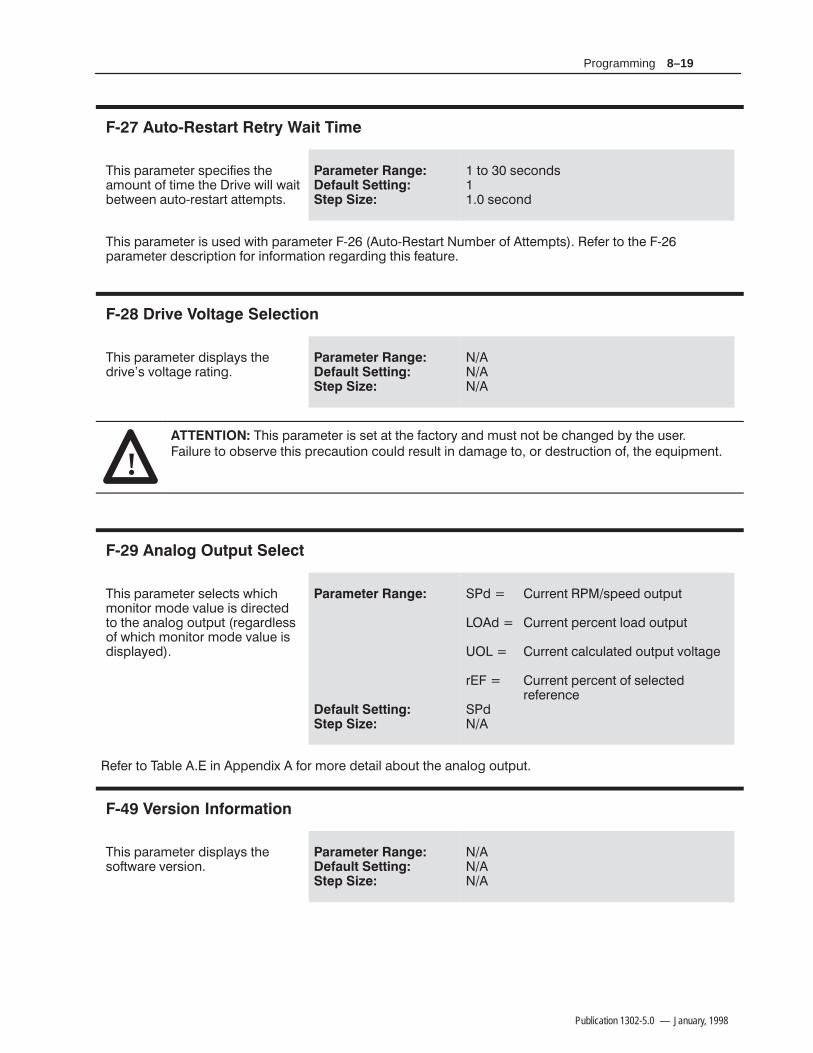
8–19Programming
Publication 1302-5.0 — January, 1998
' #"'!" " " % "
#$, )+& - + ,) $!$ , -# &(.'- (! -$& -# +$/ 0$%% 0$- -0 ' .-(3+ ,-+- -- &)-,
" #" """ &
-( , (', , ('
#$, )+& - + $, ., 0$-# )+& - + 3 .-(3 ,-+- .& + (! -- &)-, ! + -( -# 3)+& - + ,+$)-$(' !(+ $'!(+&-$(' + "+$'" -#$, ! -.+
' $ " "
#$, )+& - + $,)%2, -# +$/ , /(%-" +-$'"
" #" """ &
! #$, )+& - + $, , - - -# !-(+2 ' &.,- '(- #'" 2 -# ., +$%.+ -( (, +/ -#$, )+ .-$(' (.% + ,.%- $' &" -( (+ ,-+.-$(' (! -# *.$)& '-
' #"#" "
#$, )+& - + , % -, 0#$#&('$-(+ &( /%. $, $+ - -( -# '%(" (.-).- + "+% ,,(! 0#$# &('$-(+ &( /%. $,$,)%2
"
#" """ &
.++ '- ,) (.-).-
.++ '- ) + '- %( (.-).-
.++ '- %.%- (.-).- /(%-"
+ .++ '- ) + '- (! , % - + ! + '
! + -( % $' )) '$1 !(+ &(+ -$% (.- -# '%(" (.-).-
' ! "
#$, )+& - + $,)%2, -# ,(!-0+ / +,$('
" #" """ &

8–20 Programming
Publication 1302-5.0 — January, 1998
This Page Intentionally Blank

Chapter 99–1
Publication 1302-5.0 — January, 1998
Troubleshooting
!ATTENTION: Only qualified personnel familiar withthe 1302 Drive and associated machinery should performtroubleshooting or maintenance functions on the Drive.Failure to comply may result in personal injury and/orequipment damage.
The 1302 Drive is monitored by internal diagnostics. If a faultoccurs, the Drive displays a two-digit fault code to identify theproblem. A fault causes the Drive to coast to rest if it is running orprevents the Drive from starting if it is stopped. The fault code isalso entered into the error log.
This chapter defines the fault codes and suggests actions to correctproblems. It also describes how to access and clear the error log.
Note: Refer also to the F-26 (Auto-Restart Number of Attempts) parameter description in Chapter 8. This describes the Drive’s reaction to Drive faults if the auto-restart feature is enabled (F-26 p 0).
Important: Before servicing the Drive, verify that the DC buscapacitors have discharged as described in the following paragraphUse an isolated multimeter to measure the DC bus voltage and tomake resistance checks. Note that dedicated troubleshooting testpoints are not provided.
!ATTENTION: DC bus capacitors retain hazardousvoltages after input power has been disconnected.Disconnect and lock out power to the Drive and wait five(5) minutes for the DC bus capacitors to discharge.Failure to disconnect power could result in death orserious injury. Verify bus voltages using the procedure inthe following paragraph before beginning any checks.
The 1302 Drive’s DC bus capacitors retain hazardous voltages afterinput power has been disconnected. Perform the following stepsbefore touching any internal component
Step 1. Turn off, lock out, and tag input power to the Drive. Wait five minutes.
Step 2. Remove the Drive’s cover.
Step 3. Verify that there is no voltage at the Drive’s input power terminals.
Introduction
Verifying DC Bus Voltage

9–2 Troubleshooting
Publication 1302-5.0 — January, 1998
Step 4. Measure the DC bus voltage at the DC bus power terminals with a multimeter while standing on a non-conductive surface and wearing insulated gloves (600V). See Figure 9.1.
Once the Drive has been serviced, reattach the Drive’s cover andreapply input power.
Figure 9.1 - DC Bus Terminals
Table 9.A defines the fault codes for user-correctable faults, listspossible causes, and suggests actions to take to correct the problem.All other faults require replacement of the drive.
If a fault occurs, do the following:
Step 1. Try to clear the fault first by pressing theSTOP
RESET key or asserting the IET reset input (remote operation). If the fault reoccurs, continue with step 2.
Step 2. Refer to Table 9.A to identify the fault code and the possiblecauses.
Step 3. Perform the suggested corrective action(s).
Step 4. Clear the fault by pressing theSTOP
RESET key or asserting the IET reset input.
Table 9.A - Drive Faults and Corrective Actions
!
! "
Troubleshooting the DriveUsing Fault Codes

9–3Troubleshooting
Publication 1302-5.0 — January, 1998
(& & % ") ' '%"! '%# '%&" "' '' ' (' * !"' % (!' ' (& &"* ' (& )
!
%'"! %' &''! ! , & '"" &' %& ' %'"! %' ! , % '"#'% "% ' , #% '% &%#'"!
!&' ' "#'"! &!(% %&&'"% %! '
%) *& &'%' !'" "%*%,%(!!! "'' & !%'
!&' ' "#'"! &!(% %&&'"% %! '
!#(' ! %+ '' ' !#(' & *'! &#'"! !&'! &"'"! '%!&"% % %$(%
(& )"' & ! "* ' '%"! '%# "* '%&" ) "' '' ' (' * !"' %(!' ' !#(' ! )"' & *'! ' #%"#% %! & + ' * &"!&
! # "% " !'%+ #"*% "&& "(%& ! ' (& & '" %& '" ' #%"#%) *'! & ' %) * ('" '+ %&'%' ' %) *& %(!!! *! ' ('"(%%
!
"&& " !#(' #"*% !" ! #"*%
"* ! )"' !" ! #"*% !&' ! &"'"!'%!&"% % %$(%
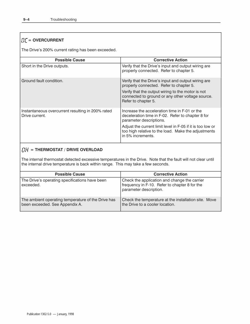
9–4 Troubleshooting
Publication 1302-5.0 — January, 1998
'+( *''#) ')# ( # -
$') # ) '+ $*)%*)( '. )) ) '+( #%*) # $*)%*) ,'# '%'$%'!. $##) ' )$ %)'
'$*# *!) $#)$# '. )) ) '+( #%*) # $*)%*) ,'# '%'$%'!. $##) ' )$ %)'
'. )) ) $*)%*) ,'# )$ ) "$)$' ( #$)$##) )$ '$*# $' #. $)' +$!) ($*'' )$ %)'
#()#)#$*( $+'*''#) '(*!)# # ')'+ *''#)
#'( ) !')$# )" # / $' )!')$# )" # / ' )$ %)' $'%'")' ('%)$#(
*() ) *''#) !") !+! # / ) ( )$$ !$, $')$$ '!)+ )$ ) !$ ) *()"#)(# #'"#)(
#)'#! )'"$()) )) -((+ )"%')*'( # ) '+ $) )) ) *!) ,!! #$) !' *#)!) #)'#! '+ )"%')*' ( ,)# '# ( ". ) , ($#(
'+( $%')# (%)$#( + #-
) %%!)$# # # ) ''''&*#. # / ' )$ %)' $' )%'")' ('%)$#
"#) $%')# )"%')*' $ ) '+ (# - %%#-
) )"%')*' ) ) #()!!)$# () $+) '+ )$ $$!' !$)$#

9–5Troubleshooting
Publication 1302-5.0 — January, 1998
! $+)'&" +!)%$ '-)$' +)"( $-$ !* & / !"* ,$+ ()'++* +! )"- %'+') )'%'-)!+"& , +' /**"- ,))&+ ."+!"& *("" ()"' '+ +!+ +! ,$+ ."$$ &'+ $) ,&+"$ +! "&(,+$"& -'$+ "* ."+!"& +! ()'() )& !"* %0 +# . *'&*
!! #! "$ "
! ,))&+ $"%"+ *++"& "& 2 "* "&'))+ +! ,))&+ $"%"+ $-$ "* +'' $'. )$+"- +' $'"&)* +! ,))&+ $-$ "& 2 ) +' !(+) ') +! ()%+) *)"(+"'&
! $+)'&" +!)%$ '-)$' *++"& "& 2 '*&'+ %+! +! %'+') & )"- '%"&+"'&
)"0 +! -$, ' 2 ) +' !(+) ') +!()%+) *)"(+"'&
! ('.) *,(($0 "* ',+ ' )&
!! #! "$ "
'**"$ ) ,$+') "$,)
STOPRESET
'&++ $$&)$0 ') **"*+& " +! ,$+
)',)* +) ()**"& +! 11#0 ') **)+"&
+! )*+ "&(,+ ') 0$"& ('.)
! -$, "& 2 "* "&'))+ ') +! )"-
!! #! "$ "
& "&-$" )"- -'$+ .* *$+ "& 2 $+ +! -'$+ +' %+! +! "&(,+ $"& -'$+
If a fault occurs, the Drive displays a fault code and logs the faultcode into the error log. If more than one fault occurs, the first faultflashes on the display and the subsequent faults (up to two) arelogged in the error log. After three faults, no subsequent faults arelogged.
The faults in the error log are numbered sequentially. For example, ifan overcurrent fault occurred first followed by a thermal overloadfault, the error log would read 1-OC, 2-OL.
The last fault to occur appears first when the error log is accessed.For example, if the last fault to occur was a low bus fault, and theerror log contained three entries, the error log would display 3-LUwhen the error log is accessed.
Accessing and Clearing theError Log
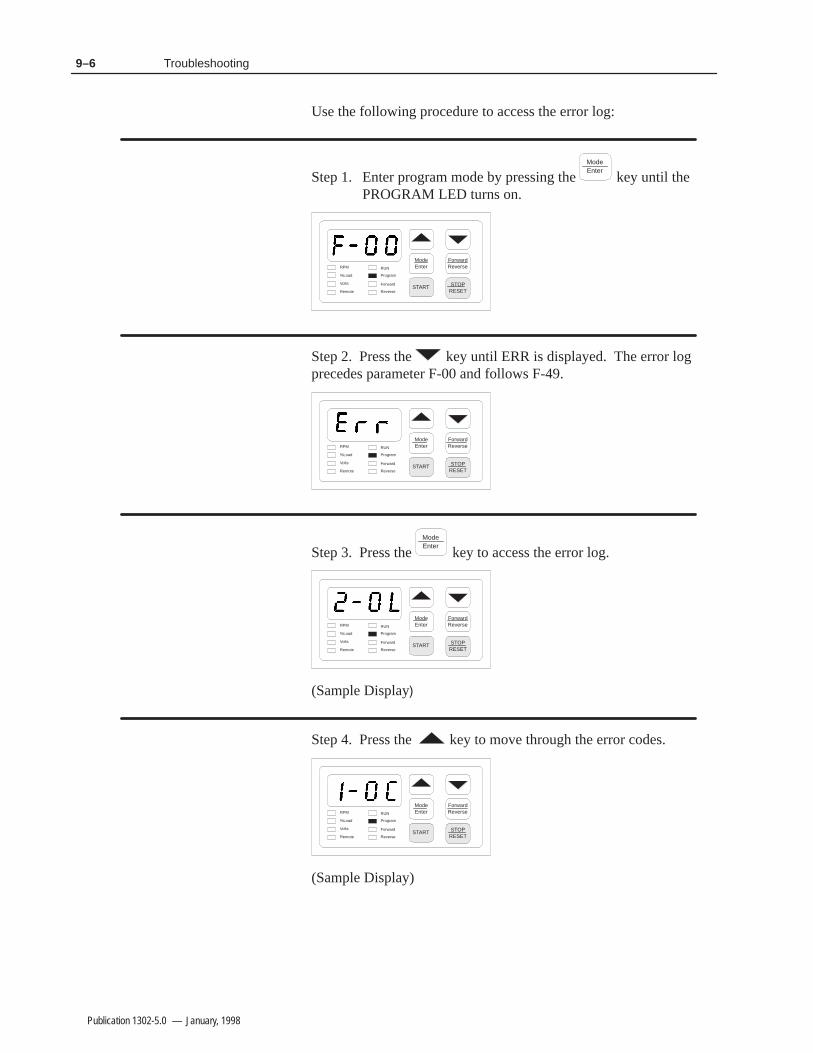
9–6 Troubleshooting
Publication 1302-5.0 — January, 1998
Use the following procedure to access the error log:
Step 1. Enter program mode by pressing the ModeEnter
key until the PROGRAM LED turns on.
ModeEnter
START
ForwardReverse
STOPRESET
RPM
%Load
Volts
Remote
RUN
Program
Forward
Reverse
Step 2. Press the key until ERR is displayed. The error logprecedes parameter F-00 and follows F-49.
ModeEnter
START
ForwardReverse
STOPRESET
RPM
%Load
Volts
Remote
RUN
Program
Forward
Reverse
Step 3. Press the ModeEnter
key to access the error log.
ModeEnter
START
ForwardReverse
STOPRESET
RPM
%Load
Volts
Remote
RUN
Program
Forward
Reverse
(Sample Display
Step 4. Press the key to move through the error codes.
ModeEnter
START
ForwardReverse
STOPRESET
RPM
%Load
Volts
Remote
RUN
Program
Forward
Reverse
(Sample Display)

9–7Troubleshooting
Publication 1302-5.0 — January, 1998
Step 5. Press theSTOP
RESET key to clear the log.
ModeEnter
START
ForwardReverse
STOPRESET
RPM
%Load
Volts
Remote
RUN
Program
Forward
Reverse
The display will return to the active monitor display.
If a fault occurs, the Drive displays a fault code and logs the faultcode into the error log. If more than one fault occurs, the first faultflashes on the display and the subsequent faults (up to two) arelogged in the error log. After three faults, no subsequent faults arelogged.
!ATTENTION: DC bus capacitors retain hazardousvoltage after input power has been disconnected.Disconnect and lock out power to the Drive and waitfive (5) minutes for the DC bus capacitors to discharge.Failure to disconnect power could result in death orserious injury. Verify bus voltages using the procedurein Chapter 9 before beginning any checks.
Use the following procedure to check the Drive’s Power Modulecircuitry. Note that this test is performed with the power off.
Step 1. Turn off and lock out input power. Wait five minutes.
Step 2. Remove the Drive’s cover.
Step 3. Verify that there is no voltage at the Drive’s input power terminals
Step 4. Check the DC bus voltage with a voltmeter as described in Chapter 9 to ensure that the DC bus capacitors are discharged.
Step 5. Disconnect the motor from the Drive.
Step 6. Check all AC line and DC bus fuses.
Step 7. If a fuse is open, use a multimeter to check the input diodes and output IGBTs. See Tables 9.B and 9.C
Step 8. Reconnect the motor to the Drive.
Step 9. Reattach the Drive’s cover.
Step 10. Reapply input power.
Power Module Check

9–8 Troubleshooting
Publication 1302-5.0 — January, 1998
Table 9.2 - Resistance Checks for Input Diodes
!!!!!!"
% # %$)!$*!)- ( %') !'*!) %' !
- %&$ , $ ) #)' !(
) !)
&%$$) ,!) '+'(&%"'!)- &%"'!)-
*( +%")( &%,' )'#!$"
. *( +%")( &%,' )'#!$"
Table 9.3 - Resistance Checks for IGBTs
!!!!!!"
% # %$)!$*!)- ( %') !'*!) %' !
- %&$ , $ ) #)' !(
) !)
&%$$) ,!) '+'(&%"'!)- &%"'!)-
*( +%")( &%,' )'#!$"
. *( +%")( &%,' )'#!$"

Appendix AA–1
Publication 1302-5.0 — January, 1998
Technical Specifications
Table A.A - Service Conditions
.2* .786.'98.32 &4&(.8=&<.191
#-6**C4-&7* B$ ;.8- B&147 7=11*86.(&0+&908 (966*28 (&4&(.8=
328630 *8-3) 00C).,.8&0 4907*C;.)8-C13)90&8*) %
&66.*6 6*59*2(= B/> B/> 36 B/> 73+8;&6* 7*0*(8&'0*
.740&(*1*28 3;*6 &(836
.2* 6*59*2(= B> @B>
.2* $308&,* $&6.&8.32 D 83
.2* .4 !.)*#-639,- B1.00.7*(32)7
.2*&6.8= "4**) 6*+*6*2(* 83 398498 +6*59*2(=
32,C8*61 6*59*2(= "8&'.0.8=
.2.191 6*59*2(= !&2,* D B>
&<.191 6*59*2(= !&2,* D B>
&<.191 3&) +36 1.298* '&7*) 32 6.:* 2&1*40&8* 6&8.2,
3836 *&) *2,8-7 B1*8*67 B+**8 838&0 (See table 3.7 for moreinformation)
:*6(966*28 #6.4 # 6&8*) 6.:* (966*28
Table A.B - Dimensions
2(03796* *.,-8 *48- %.)8- %*.,-8
B11 B11 B11 B/, 0'
B11 11 B11 B/, 0'
Table A.C - Environmental Conditions
4*6&8.2, #*14*6&896* ? 83 A? ? 83 ? D *2(037*) 6.:*7
? 83 A? ? 83 ? D 34*2 (-&77.7 (3:*6 6*13:*)
"836&,* #*14*6&896* DAA? 83 ? DAA? 83 ?
91.).8= 83 232C(32)*27.2,
08.89)* 3 238 .278&00 8-* 6.:* &'3:* B1*8*67 B+**8 ;.8-398)*6&8.2, 398498 43;*6 36 *:*6= B1*8*67 B+**8 &'3:*B1*8*67 B+**8 94 83 B1*8*67 B+**8)*6&8* 8-* 398498 (966*28 '= '3:* B1*8*67B+**8 (328&(8 =396 03(&0 00*26&)0*= 7&0*7 3++.(* +36&77.78&2(*

Technical SpecificationsA–2
Publication 1302-5.0 — January, 1998
)
Table A.D - Drive Inputs/#-0) 1''& '('2'/%' 40 :! 02 40 :.
4#24 &)';3'/3+4+6' 3+)/#- 4*#4 .534 3'' #/ 01'/;40;%-03'& %0/4#%442#/3+4+0/ *+3 42#/3+4+0/ .#9 $' # .0.'/4#29 02 (+8'& %-0352'
401 / 01'/ %0/4#%4 4*#4 .534 $' %-03'& 7*'/ 4*' 2+6' +3 25//+/)*' 2+6' 7+-- 2'.#+/ 0(( #3 -0/) #3 4*' %0/4#%4 +3 01'/
'3'4 &)';3'/3+4+6' 3+)/#- 4*#4 .534 3'' #/ 01'/;40;%-03'& %0/4#%442#/3+4+0/ *+3 42#/3+4+0/ .#9 $' # .0.'/4#29 02 (+8'& %-0352'
027#2&'6'23' / 01'/ %0/4#%4 40 #33'24 4*' (027#2& &+2'%4+0/ #/& # %-03'&%0/4#%4 40 #33'24 4*' 2'6'23' &+2'%4+0/
5/%4+0/ 033 / 01'/ %0/4#%4 4*#4 .534 $' %-03'& 7*'/ 4*' 2+6' +3 25//+/)"*'/ 4*' %0/4#%4 +3 01'/ 4*' 2+6' 452/3 0(( *' 2+6' 7+-- 2'.#+/0(( #3 -0/) #3 4*' %0/4#%4 +3 01'/
Table A.E - Drive Outputs/#-0) 54154
;:! 3%#-'& 3+)/#-
*' 3%#-'& 3+)/#- +3 3'-'%4'& 4*205)* 1#2#.'4'2 ; #/& %#/ $'0/' 0( 4*' (0--07+/)
54154 !0-4#)' 40 !
0#& .13 40 '2%'/4#)' 0( 054154 #.13$#3'& 0/ 4*' 2+6' /#.'1-#4'
/)+/''2+/) /+4 +/+.5. 40 .#8+.5. 02.+/+.5. 40 .#8+.5. 0( #/9'/)+/''2+/) 5/+4 '' 1#2#.'4'2;
'-'%4'& 1''& '('2'/%' 40 '2%'/4#)' 0(4*' 3'-'%4'& 2'('2'/%'3+)/#- 2#/)'
/5$$'2 '3+3402 2#,+/) /5$$'2 2'3+3402 %0/420- 3+)/#- 53'& $9 #/ 014+0/#- 3/5$$'22'3+3402
54154 4#453 '-#9 ! ! .1 2'-#9 054154 /' 02. #/& 0/'02. %0/4#%4 7+2'& 7+4* # 3+/)-' %0..0/
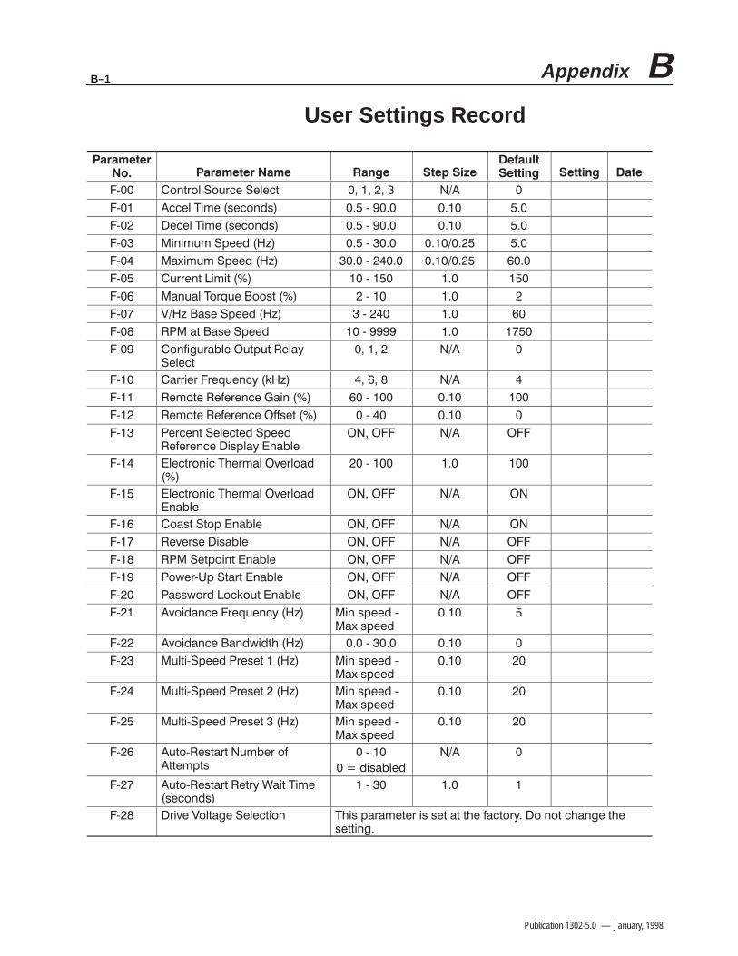
Appendix BB–1
Publication 1302-5.0 — January, 1998
User Settings Record
? 328630 !396(* !*0*(8
? ((*0 ".1* 7*(32)7 ?
? *(*0 ".1* 7*(32)7 ?
? .2.191 !4**) > ?
? &<.191 !4**) > ?
? 966*28 .1.8 ?
? &29&0 "3659* 3378 ?
? $> &7* !4**) > ?
? &8 &7* !4**) ?
? 32+.,96&'0* 98498 *0&=!*0*(8
? &66.*6 6*59*2(= />
? *138* *+*6*2(* &.2 ?
? *138* *+*6*2(* ++7*8 ?
? *6(*28 !*0*(8*) !4**) *+*6*2(* .740&= 2&'0*
? 0*(8632.( "-*61&0 :*603&)
?
? 0*(8632.( "-*61&0 :*603&)2&'0*
? 3&78 !834 2&'0*
? *:*67* .7&'0*
? !*843.28 2&'0*
? 3;*6?#4 !8&68 2&'0*
? &77;36) 3(/398 2&'0*
? :3.)&2(* 6*59*2(= > .2 74**) ?&< 74**)
? :3.)&2(* &2);.)8- > ?
? 908.?!4**) 6*7*8 > .2 74**) ?&< 74**)
? 908.?!4**) 6*7*8 > .2 74**) ?&< 74**)
? 908.?!4**) 6*7*8 > .2 74**) ?&< 74**)
? 983? *78&68 91'*6 3+88*1487
?
).7&'0*)
? 983? *78&68 *86= %&.8 ".1*7*(32)7
?
? 6.:* $308&,* !*0*(8.32 "-.7 4&6&1*8*6 .7 7*8 &8 8-* +&(836= 3 238 (-&2,* 8-*7*88.2,

User Settings RecordB–2
Publication 1302-5.0 — January, 1998
% "!"! !
% ! ### $

Appendix CC–1
Publication 1302-5.0 — January, 1998
Parameter Listing (Alphabetical)
Acceleration Time F-01. . . . . . . . . . . . . . . . . . . . . . . . . . . . . . . . . . . . . .
Analog Output Select F-29. . . . . . . . . . . . . . . . . . . . . . . . . . . . . . . . . . .
Auto-Restart Number of Attempts F-26. . . . . . . . . . . . . . . . . . . . . . . . .
Auto-Restart Retry Wait Time F-27. . . . . . . . . . . . . . . . . . . . . . . . . . . . .
Avoidance Bandwidth F-22. . . . . . . . . . . . . . . . . . . . . . . . . . . . . . . . . . .
Avoidance Frequency F-21. . . . . . . . . . . . . . . . . . . . . . . . . . . . . . . . . . .
Carrier Frequency F-10. . . . . . . . . . . . . . . . . . . . . . . . . . . . . . . . . . . . . .
Coast Stop Enable F-16. . . . . . . . . . . . . . . . . . . . . . . . . . . . . . . . . . . . . .
Configurable Output Relay Select F-09. . . . . . . . . . . . . . . . . . . . . . . . . .
Control Source Select F-00. . . . . . . . . . . . . . . . . . . . . . . . . . . . . . . . . . .
Current Limit F-05. . . . . . . . . . . . . . . . . . . . . . . . . . . . . . . . . . . . . . . . . .
Deceleration Rate F-02. . . . . . . . . . . . . . . . . . . . . . . . . . . . . . . . . . . . . .
Drive Voltage Selection F-28. . . . . . . . . . . . . . . . . . . . . . . . . . . . . . . . . .
Electronic Thermal Overload F-14. . . . . . . . . . . . . . . . . . . . . . . . . . . . .
Electronic Thermal Overload Enable F-15. . . . . . . . . . . . . . . . . . . . . . .
Manual Torque Boost F-06. . . . . . . . . . . . . . . . . . . . . . . . . . . . . . . . . . .
Maximum Speed F-04. . . . . . . . . . . . . . . . . . . . . . . . . . . . . . . . . . . . . . .
Minimum Speed F-03. . . . . . . . . . . . . . . . . . . . . . . . . . . . . . . . . . . . . . .
Multi-Speed Preset 1 F-23. . . . . . . . . . . . . . . . . . . . . . . . . . . . . . . . . . . .
Multi-Speed Preset 2 F-24. . . . . . . . . . . . . . . . . . . . . . . . . . . . . . . . . . . .
Multi-Speed Preset 3 F-25. . . . . . . . . . . . . . . . . . . . . . . . . . . . . . . . . . . .
Password Lockout Enable F-20. . . . . . . . . . . . . . . . . . . . . . . . . . . . . . . .
Percent Selected Speed Reference Display Enable F-13. . . . . . . . . . . . .
Power-Up Start Enable F-19. . . . . . . . . . . . . . . . . . . . . . . . . . . . . . . . . .
Remote Reference Gain F-11. . . . . . . . . . . . . . . . . . . . . . . . . . . . . . . . . .
Remote Reference Offset F-12. . . . . . . . . . . . . . . . . . . . . . . . . . . . . . . .
Reverse Disable F-17. . . . . . . . . . . . . . . . . . . . . . . . . . . . . . . . . . . . . . . .
RPM at Base Speed F-08. . . . . . . . . . . . . . . . . . . . . . . . . . . . . . . . . . . . .
RPM Setpoint Enable F-18. . . . . . . . . . . . . . . . . . . . . . . . . . . . . . . . . . .
V/Hz (Base Speed) F-07. . . . . . . . . . . . . . . . . . . . . . . . . . . . . . . . . . . . .
Version Information F-49. . . . . . . . . . . . . . . . . . . . . . . . . . . . . . . . . . . . .

Parameter Listing (Alphabetical)C–2
Publication 1302-5.0 — January, 1998
This Page Intentionally Blank
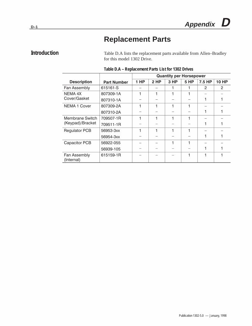
Appendix DD–1
Publication 1302-5.0 — January, 1998
Replacement Parts
Table D.A lists the replacement parts available from Allen–Bradleyfor this model 1302 Drive.
Table D.A – Replacement Parts List for 1302 Drives
( ,,!'&2 3 4 4
)/!+,%!-
3
3
4
4
4
4
4
4
)/!+ 3
3
4
4
4
4
4
4
!'+(! 0$-#!2* +%!-
3
3
4
4
4
4
4
4
!".&-)+ 311
311
4
4
4
4
4
4
*$-)+ 3
3
4
4
4
4
4
4
4
4
( ,,!'&2(-!+(&
3 4 4 4
Introduction

Replacement PartsD–2
Publication 1302-5.0 — January, 1998
This Page Intentionally Blank
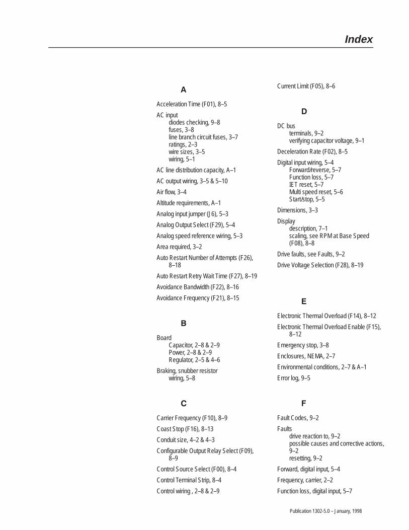
Publication 1302-5.0 – January, 1998
Acceleration Time (F01), 8–5
AC inputdiodes checking, 9–8fuses, 3–8line branch circuit fuses, 3–7ratings, 2–3wire sizes, 3–5wiring, 5–1
AC line distribution capacity, A–1
AC output wiring, 3–5 & 5–10
Air flow, 3–4
Altitude requirements, A–1
Analog input jumper (J6), 5–3
Analog Output Select (F29), 5–4
Analog speed reference wiring, 5–3
Area required, 3–2
Auto Restart Number of Attempts (F26),8–18
Auto Restart Retry Wait Time (F27), 8–19
Avoidance Bandwidth (F22), 8–16
Avoidance Frequency (F21), 8–15
BoardCapacitor, 2–8 & 2–9Power, 2–8 & 2–9Regulator, 2–5 & 4–6
Braking, snubber resistorwiring, 5–8
Carrier Frequency (F10), 8–9
Coast Stop (F16), 8–13
Conduit size, 4–2 & 4–3
Configurable Output Relay Select (F09),8–9
Control Source Select (F00), 8–4
Control Terminal Strip, 8–4
Control wiring , 2–8 & 2–9
Current Limit (F05), 8–6
DC busterminals, 9–2verifying capacitor voltage, 9–1
Deceleration Rate (F02), 8–5
Digital input wiring, 5–4Forward/reverse, 5–7Function loss, 5–7IET reset, 5–7Multi speed reset, 5–6Start/stop, 5–5
Dimensions, 3–3
Displaydescription, 7–1scaling, see RPM at Base Speed(F08), 8–8
Drive faults, see Faults, 9–2
Drive Voltage Selection (F28), 8–19
Electronic Thermal Overload (F14), 8–12
Electronic Thermal Overload Enable (F15),8–12
Emergency stop, 3–8
Enclosures, NEMA, 2–7
Environmental conditions, 2–7 & A–1
Error log, 9–5
Fault Codes, 9–2
Faultsdrive reaction to, 9–2possible causes and corrective actions,9–2resetting, 9–2
Forward, digital input, 5–4
Frequency, carrier, 2–2
Function loss, digital input, 5–7
Index

IndexI–2
Publication 1302-5.0 – January, 1998
Grounding, 5–10
Humidity, A–1
IET reset, digital input, 5–7
IGBT power deviceschecking, 9–8Input, AC, 2–2
Jumper (J6) location of, 4–6
Lead lengths, motor, 3–6
LED descriptions, 7–3
Line frequency, A–1
Line noise, avoiding, 4–5
Manual Torque Boost (F06), 8–7
Maximum Speed (F04), 8–6
Mechanical motor overload protection, 4–5
Membrane switch/bracket assembly, 2–8 &2–9
Minimum Speed (F03), 8–5
Model numbers, 2–6
Monitor mode, 7–6
Motorlead lengths, 3–6multiple motor applications, 3–6 & 3–9overload protection, mechanical, 4–5single motor applications, 3–6 & 3–9
Mounting dimensions, 3–3
Multi–Speed Presets 1,2,3 (F–23, F–24,F–25), 8–17
Multi–Speed presets, digital inputs, 5–6
NEMA enclosures, 2–7
Option kits, 2–7
Outputcurrent, 2–8power wiring, 5–10status relay wiring, 5–9
Parametersdisplaying or changing values, 8–1factory settings and defaults, B–1listed alphabetically, C–1menu structure, 7–5password protection, 8–2record of user settings, D–1
Parts, replacement, D–1
Password protection, 8–2
Percent Selected Speed Reference DisplayEnable (F–13), 8–11
Planningdrive clearance 3 - 2 & 3 - 4location, 3–2 & 3–4
Power loss ratings, 3–2, 3–4wire sizes, 3–2 & 3–4
Power Modulechecking circuitry with power off, 9–7
Power Up Start Enable (F19), 8–14
Program mode, 8–1
RatingsAC input, 2–3NEMA, 2–7power, 2–1power loss, 2–1
Regulator Board, 2–5
Remote Reference Gain (F–11
Remote Reference Offset (F–12
Replacement parts
Reset, digital input, 5–5

Index I–3
Publication 1302-5.0 – January, 1998
Resistor, snubber braking, 2–7
Reverse, digital input, 5–7
Reverse Disable (F–17), 8–13
Routing, wire, 4–1
RPM at Base Speed (F–08), 8–8
RPM at Setpoint Enable (F–18), 8–14
" $ * )&". $(($ 7–7
$" - ( $ 3–5 & 5–3
* ('+ (#$*) 3–2
$+( () )*%( (! $ 2–7
& * %$)%$+ * %&$ $ ) /) 4–2 & 4–3$, (%$#$*" A–1 #$) %$) A–1( , $&+*) A–2( , %+*&+*) A–2)(, %$ * %$) A–1*(# $" *%('+ (* $) 3–5- ( ) /) 3–5
*(* *" $&+* 5–5
*%& *" $&+* 5–5
*%&& $ * ( , 5–8
(# $" *( &*%('+ )& * %$) 3–5
- ( ) /) 3–5- ( $ 3–5
)* $ 9–8
%('+ )& * %$) 3–5
($)%(#( )%"* %$ 4–4
$* "* %$ ) ( "%- 3–4
() %$ $%(#* %$ 8–19
/ ) & 8–7
*) A–1
( (%+* $ 4–2 & 4–3

IndexI–4
Publication 1302-5.0 – January, 1998
This Page Intentionally Blank

Index I–5
Publication 1302-5.0 – January, 1998
This Page Intentionally Blank

IndexI–6
Publication 1302-5.0 – January, 1998
This Page Intentionally Blank

Publication XXXX-8X.X – September 1995
Allen-Bradley, a Rockwell Automation Business, has been helping its customers improveproductivity and quality for more than 90 years. We design, manufacture and support a broadrange of automation products worldwide. They include logic processors, power and motioncontrol devices, operator interfaces, sensors and a variety of software. Rockwell is one of theworld’s leading technology companies.
Worldwide representation.
Argentina • Australia • Austria • Bahrain • Belgium • Brazil • Bulgaria • Canada • Chile • China, PRC • Colombia • Costa Rica • Croatia • Cyprus • Czech Republic •Denmark • Ecuador • Egypt • El Salvador • Finland • France • Germany • Greece • Guatemala • Honduras • Hong Kong • Hungary • Iceland • India • Indonesia • Ireland • Israel • Italy • Jamaica • Japan • Jordan • Korea • Kuwait • Lebanon • Malaysia • Mexico • Netherlands • New Zealand • Norway • Pakistan • Peru •Philippines • Poland • Portugal • Puerto Rico • Qatar • Romania • Russia–CIS • Saudi Arabia • Singapore • Slovakia • Slovenia • South Africa, Republic • Spain •Sweden • Switzerland • Taiwan • Thailand • Turkey • United Arab Emirates • United Kingdom • United States • Uruguay • Venezuela • Yugoslavia
Allen-Bradley Headquarters, 1201 South Second Street, Milwaukee, WI 53204 USA, Tel: (1) 414 382-2000 Fax: (1) 414 382-4444
Publication 1302-5.0 – January ,1998 P/N 189386 (01)Copyright 1998 Allen-Bradley Company, Inc. Printed in USA