57880 pcr manual 2006 - auburn university · pdf fileiec 61000-4-2 electromagnetic...
TRANSCRIPT

Raleigh, NC 27604 USA Phone: 919-255-3220 • Toll Free: 800-849-0472 • Fax: 919-255-6120Website: www.aircleansystems.com • Email: [email protected]
* Product designs are subject to change without notice. © 2006 AirClean® Systems 57880 Rev. 4
OPERATORS MANUAL
DUCTLESS PCR WORKSTATION
Class 100 Vertical Laminar Flow & Timed UV Light with UVTect™ Controller

2
SECTION PAGE Declaration of Conformity 3 Symbols and Definitions 4 Cautions and Precautions 5 Technical Specifications 6-7 Overview 8 Unpacking and Installation 9-11 Controller Instructions 12 Programming Menus 13 Operating Instructions 14 Alarm Messages 14 Maintenance: • Filters 15-17 • Bulbs 17-19 • Controller 19-20 • Cleaning 21 Spare Parts List 22 Warranty 23 Options 24-25 Shipping Claims 26 Contact Information 27
FIGURES PAGE Figure 1, Airflow pattern 8 Figure 2, Unpacking the workstation 9 Figure 3, Lifting the workstation properly 10 Figure 4, Pre-filter and swell latch locations 10 Figure 5, Door switch, UV lamp and linecord connections 11 Figure 6, Control panel layout 12 Figure 7, HEPA filter replacement 16 Figure 8, Fluorescent bulb replacement 17 Figure 9, Removing the UVTect™ controller from the AC632 model 19 Figure 10, Removing the UVTect™ controller from the AC648 model 20
CONTENTS
3
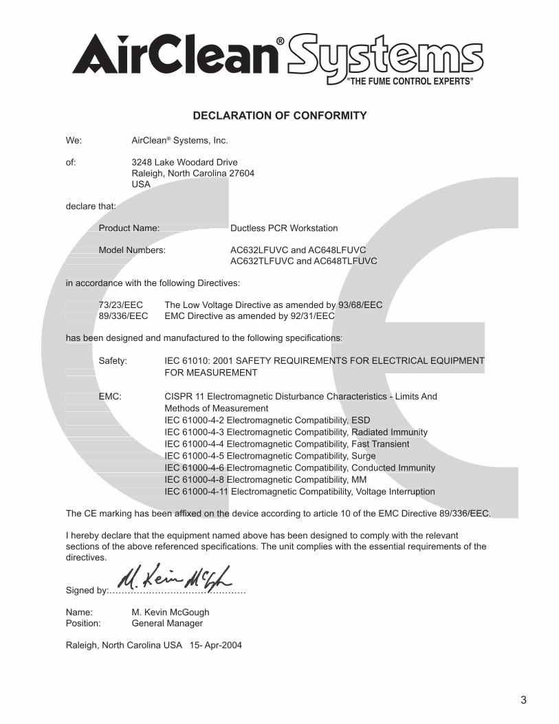
DECLARATION OF CONFORMITY
We: AirClean® Systems, Inc.
of: 3248 Lake Woodard Drive Raleigh, North Carolina 27604 USA
declare that:
Product Name: Ductless PCR Workstation
Model Numbers: AC632LFUVC and AC648LFUVC AC632TLFUVC and AC648TLFUVC
in accordance with the following Directives:
73/23/EEC The Low Voltage Directive as amended by 93/68/EEC 89/336/EEC EMC Directive as amended by 92/31/EEC
has been designed and manufactured to the following specifi cations:
Safety: IEC 61010: 2001 SAFETY REQUIREMENTS FOR ELECTRICAL EQUIPMENT FOR MEASUREMENT EMC: CISPR 11 Electromagnetic Disturbance Characteristics - Limits And Methods of Measurement IEC 61000-4-2 Electromagnetic Compatibility, ESD IEC 61000-4-3 Electromagnetic Compatibility, Radiated Immunity IEC 61000-4-4 Electromagnetic Compatibility, Fast Transient IEC 61000-4-5 Electromagnetic Compatibility, Surge IEC 61000-4-6 Electromagnetic Compatibility, Conducted Immunity IEC 61000-4-8 Electromagnetic Compatibility, MM IEC 61000-4-11 Electromagnetic Compatibility, Voltage Interruption
The CE marking has been affi xed on the device according to article 10 of the EMC Directive 89/336/EEC.
I hereby declare that the equipment named above has been designed to comply with the relevant sections of the above referenced specifi cations. The unit complies with the essential requirements of the directives.
Signed by:………………………………………
Name: M. Kevin McGoughPosition: General Manager
Raleigh, North Carolina USA 15- Apr-2004
Model Numbers: AC632LFUVC and AC648LFUVC AC632TLFUVC and AC648TLFUVC
73/23/EEC The Low Voltage Directive as amended by 93/68/EEC 89/336/EEC EMC Directive as amended by 92/31/EEC
has been designed and manufactured to the following specifi cations:
Safety: IEC 61010: 2001 SAFETY REQUIREMENTS FOR ELECTRICAL EQUIPMENT
EMC: CISPR 11 Electromagnetic Disturbance Characteristics - Limits And
IEC 61000-4-2 Electromagnetic Compatibility, ESD IEC 61000-4-3 Electromagnetic Compatibility, Radiated Immunity IEC 61000-4-4 Electromagnetic Compatibility, Fast Transient IEC 61000-4-5 Electromagnetic Compatibility, Surge IEC 61000-4-6 Electromagnetic Compatibility, Conducted Immunity
IEC 61000-4-11 Electromagnetic Compatibility, Voltage Interruption
The CE marking has been affi xed on the device according to article 10 of the EMC Directive 89/336/EEC.
Raleigh, North Carolina 27604
declare that:
Product Name: Ductless PCR Workstation
Model Numbers: AC632LFUVC and AC648LFUVC AC632TLFUVC and AC648TLFUVC
in accordance with the following Directives:
73/23/EEC The Low Voltage Directive as amended by 93/68/EEC 89/336/EEC EMC Directive as amended by 92/31/EEC
has been designed and manufactured to the following specifi cations:
FOR MEASUREMENT
EMC: CISPR 11 Electromagnetic Disturbance Characteristics - Limits And Methods of Measurement IEC 61000-4-2 Electromagnetic Compatibility, ESD IEC 61000-4-3 Electromagnetic Compatibility, Radiated Immunity IEC 61000-4-4 Electromagnetic Compatibility, Fast Transient IEC 61000-4-5 Electromagnetic Compatibility, Surge IEC 61000-4-6 Electromagnetic Compatibility, Conducted Immunity IEC 61000-4-8 Electromagnetic Compatibility, MM IEC 61000-4-11 Electromagnetic Compatibility, Voltage Interruption
The CE marking has been affi xed on the device according to article 10 of the EMC Directive 89/336/EEC.
4
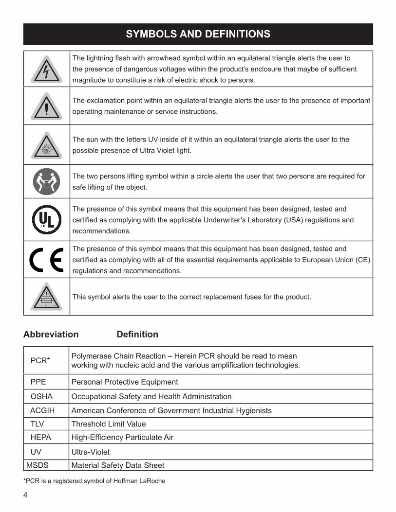
The lightning flash with arrowhead symbol within an equilateral triangle alerts the user to the presence of dangerous voltages within the product’s enclosure that maybe of sufficient magnitude to constitute a risk of electric shock to persons.
The exclamation point within an equilateral triangle alerts the user to the presence of important operating maintenance or service instructions.
The sun with the letters UV inside of it within an equilateral triangle alerts the user to the possible presence of Ultra Violet light.
The two persons lifting symbol within a circle alerts the user that two persons are required for safe lifting of the object.
The presence of this symbol means that this equipment has been designed, tested and certified as complying with the applicable Underwriter’s Laboratory (USA) regulations and recommendations.
The presence of this symbol means that this equipment has been designed, tested and certified as complying with all of the essential requirements applicable to European Union (CE) regulations and recommendations.
This symbol alerts the user to the correct replacement fuses for the product.
Abbreviation Definition
PCR* Polymerase Chain Reaction – Herein PCR should be read to meanworking with nucleic acid and the various amplification technologies.
PPE Personal Protective Equipment
OSHA Occupational Safety and Health Administration
ACGIH American Conference of Government Industrial Hygienists
TLV Threshold Limit Value
HEPA High-Efficiency Particulate Air
UV Ultra-Violet
MSDS Material Safety Data Sheet
*PCR is a registered symbol of Hoffman LaRoche
SYMBOLS AND DEFINITIONS
5
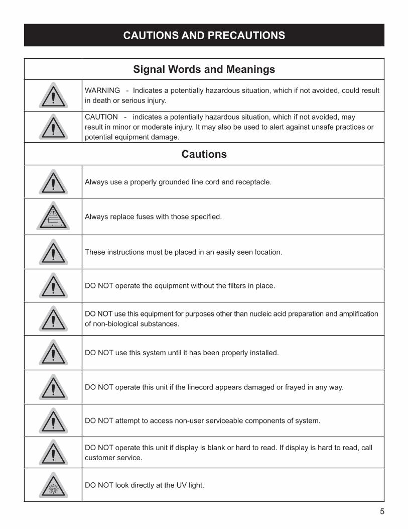
Signal Words and Meanings
WARNING - Indicates a potentially hazardous situation, which if not avoided, could result in death or serious injury.
CAUTION - indicates a potentially hazardous situation, which if not avoided, may result in minor or moderate injury. It may also be used to alert against unsafe practices or potential equipment damage.
Cautions
Always use a properly grounded line cord and receptacle.
Always replace fuses with those specified.
These instructions must be placed in an easily seen location.
DO NOT operate the equipment without the filters in place.
DO NOT use this equipment for purposes other than nucleic acid preparation and amplification of non-biological substances.
DO NOT use this system until it has been properly installed.
DO NOT operate this unit if the linecord appears damaged or frayed in any way.
DO NOT attempt to access non-user serviceable components of system.
DO NOT operate this unit if display is blank or hard to read. If display is hard to read, call customer service.
DO NOT look directly at the UV light.
CAUTIONS AND PRECAUTIONS

6
TECHNICAL SPECIFICATIONSSPECIFICATIONS AC632LFUVC AC648LFUVCPhysical DimensionsOutside Dimensions 32”w x 30”h x 24”d 48”w x 31”h x 24”dInside Dimensions 31”w x 20”h x 23”d 47”w x 20”h x 23”dWeight, including filters 100 lbs. 150 lbs.Airflow CharacteristicsLow Airflow Alarm Audible/Visual Audible/VisualVolume of Filtered Air 200 CFM 400 CFMLinear Face Velocity 50 FPM 100 FPMElectricalVoltage 110VAC 60 Hz or 230VAC50 Hz 110VAC 60 Hz or 230VAC50 HzCurrent 1.4A / .7A 2.8A /1.4APower Consumption 150W 300WMains Fluctuation ±10% ±10%FusesType 3A 250V, Slow Blow 5 X 20 6.3A 250V, Slow Blow 5 X 20Requirements 1 (110V) / 2 (230V) 1 (110V) / 2 (230V)EnvironmentalUsage Indoor Use Only Indoor Use OnlyAltitude Up to 2000m Up to 2000mHumidity 80% Max up to 31C Decreasing
Linearly to 50% at 40C80% Max up to 31C Decreasing Linearly to 50% at 40C
Installation Category II IIPollution Degree 2 2OperationSpeed Selection Variable Speed Variable SpeedConstructionTop Material ABS ABSFront Panel and Sides (3) Lexan™ Polycarbonate Lexan™ PolycarbonateBase Material Structural Polypropylene Structural PolypropylenePrefilter1Type ACFLFPRE ACFLFPRE-18Weight 8 oz. 6 lbs.Dimensions 24”l x 12”w x 3”h 18”l x 12”w x 3”hRequirements 1 2OptionsCart w/ two 4” locking wheels 32”l x 24”w x 34”h 48”l x 24”w x 34”h
1. The AC600 Series LFUVC Model Workstation is shipped with a prefilter secured on the top of the head assembly. Prefilters are designed to remove initial room air particulate and are 95% efficient for particulate down to .5 microns in diameter. Prefilters must be checked on a scheduled basis. Refer to the MAINTENANCE section of this manual.2. The AC600 Series LFUVC Model Workstation is shipped with the ACFHEPA filter installed. This filter is used for the containment of airborne particulate and to provide a Class 100 clean work environment for the user. This workstation will not neutralize any fumes The ACFHEPA filter must be changed on a scheduled basis. Refer to the MAINTENANCE section of this manual.
7
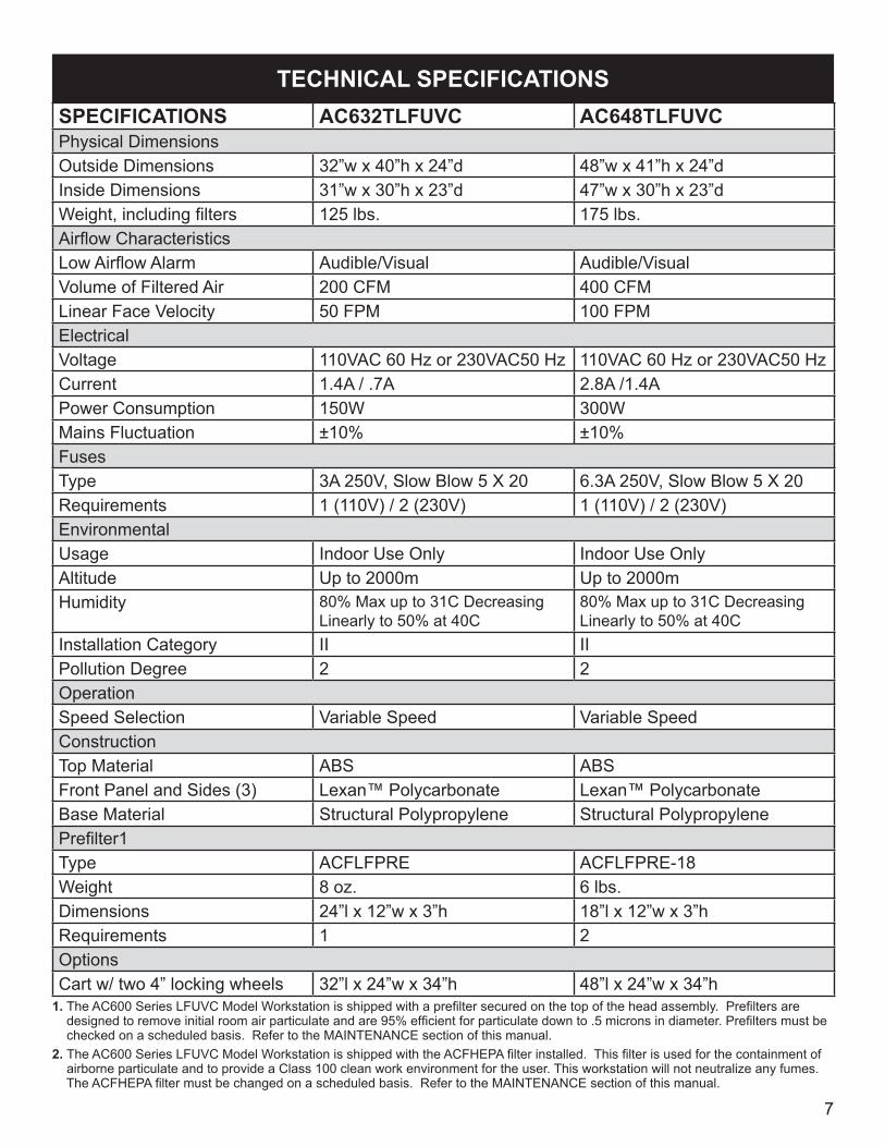
TECHNICAL SPECIFICATIONSSPECIFICATIONS AC632TLFUVC AC648TLFUVCPhysical DimensionsOutside Dimensions 32”w x 40”h x 24”d 48”w x 41”h x 24”dInside Dimensions 31”w x 30”h x 23”d 47”w x 30”h x 23”dWeight, including filters 125 lbs. 175 lbs.Airflow CharacteristicsLow Airflow Alarm Audible/Visual Audible/VisualVolume of Filtered Air 200 CFM 400 CFMLinear Face Velocity 50 FPM 100 FPMElectricalVoltage 110VAC 60 Hz or 230VAC50 Hz 110VAC 60 Hz or 230VAC50 HzCurrent 1.4A / .7A 2.8A /1.4APower Consumption 150W 300WMains Fluctuation ±10% ±10%FusesType 3A 250V, Slow Blow 5 X 20 6.3A 250V, Slow Blow 5 X 20Requirements 1 (110V) / 2 (230V) 1 (110V) / 2 (230V)EnvironmentalUsage Indoor Use Only Indoor Use OnlyAltitude Up to 2000m Up to 2000mHumidity 80% Max up to 31C Decreasing
Linearly to 50% at 40C80% Max up to 31C Decreasing Linearly to 50% at 40C
Installation Category II IIPollution Degree 2 2OperationSpeed Selection Variable Speed Variable SpeedConstructionTop Material ABS ABSFront Panel and Sides (3) Lexan™ Polycarbonate Lexan™ PolycarbonateBase Material Structural Polypropylene Structural PolypropylenePrefilter1Type ACFLFPRE ACFLFPRE-18Weight 8 oz. 6 lbs.Dimensions 24”l x 12”w x 3”h 18”l x 12”w x 3”hRequirements 1 2OptionsCart w/ two 4” locking wheels 32”l x 24”w x 34”h 48”l x 24”w x 34”h
1. The AC600 Series LFUVC Model Workstation is shipped with a prefilter secured on the top of the head assembly. Prefilters are designed to remove initial room air particulate and are 95% efficient for particulate down to .5 microns in diameter. Prefilters must be checked on a scheduled basis. Refer to the MAINTENANCE section of this manual.2. The AC600 Series LFUVC Model Workstation is shipped with the ACFHEPA filter installed. This filter is used for the containment of airborne particulate and to provide a Class 100 clean work environment for the user. This workstation will not neutralize any fumes. The ACFHEPA filter must be changed on a scheduled basis. Refer to the MAINTENANCE section of this manual.

8
OVERVIEW
The AC600 Series LFUVC Model Workstation, with UVTect™ microprocessor-driven control, allows the operator to maintain a Class 100 clean work area during PCR preparation (nucleic acid preparation) and amplification. Airborne contaminants are eliminated through pre-filter and HEPA filtration. Class 100, vertical laminar airflow bathes the work surface and provides positive pressure at the face of the unit. The positive pressure eliminates potential airborne contaminants that may enter the workstation during amplification. UVTect™ provides variable speed blower control allowing the operator to increase or decrease airflow relevant to the application requirements. UVTect™ also provides constant monitoring of the filter, with audible/visual alarms to alert the user of a blocked filter.
The LFUVC model also provides 254 nm short-wave UV light to effectively destroy contaminating DNA and RNA within minutes. Short-wave UV bulbs (254 nm) have a definable useful life of 1000 hours in the AirClean® Systems PCR workstation. The UVTect™ Controller tracks UV bulb hours and alerts the user when to replace the UV bulb. The AirClean™ Systems PCR Combination Workstation with UVTect™ controller ensures unmatched process protection and prevents operator exposure to short-wave UV energy.
AIRFLOW PATTERN 1) Room air enters at “A”. 2) Air is forced through pre-filter and HEPA filter creating laminar flow. 3) Clean laminar flow air enters work area at “B” and exits at “C”.
Figure 1, Airflow pattern
WARNING: THIS WORKSTATION IS NOT DESIGNED FOR USE WITH BIOLOGICAL SAMPLES.

9
1) Make sure that your workstation arrived secured to a pallet/skid. Inspect the exterior packaging (box) for damage. Note any damage or absence of pallet on the freight carrier’s waybill and call AirClean® Systems immediately. 2) Put on safety glasses and cut banding material. 3) Remove box top and sleeve. 4) Remove shrink-wrap and foam. If you use a sharp object to cut the shrink-wrap and foam, make sure not to cut into the workstation.
UNPACKING AND INSTALLATION INSTRUCTIONS
Figure 2, Unpacking the workstation
Note: Ready access is required to the power entry module and On/Off switchlocated at the upper, rear corner behind the UVTect™ controller.
CAUTION: This workstation should not be installed near doors, windows or air conditioning/ heating/ ventilation systems. Air must be allowed to circulate freely around the enclosure. Allow at least 3” between the top of the enclosure and any overhead cabinets or shelving for adequate air intake.
5) If ordered, assemble the mobile cart. Assembly instructions are included with the cart and also in the OPTIONS section of this manual. (page 23) 6) Designate the appropriate installation location. Make sure that the desired area is stable enough to hold the workstation and that there is an appropriate AC wall receptacle near the workstation. Do not place workstations near doors or windows.
CAUTION: DO NOT lift the workstation by the head assembly, the sash, or any protruding wires.
7) With the help of a co-worker, lift the workstation out of the bottom tray of the box. Make sure to lift from the bottom of the workstation. See figure 3.

10
8) Place the workstation in the desired location. Once in place, make sure that it is secure and stable. 9) Visually inspect your workstation, checking for any damage that may have occurred in shipping. Pay special attention to the sash hinges. If damage has occurred, call AirClean®
Systems immediately. DO NOT attempt to use workstation. 10) Remove the pre-filter for inspection before use. Refer to the MAINTENANCE section of this manual for complete instructions. (page 16) 11) Make sure that the swell latches, located on the side lip of the head assembly, are in the latched position and that the head assembly is secure and properly seated. See figure 4.
Figure 4, Pre-filter and swell latch locations.
12) Make sure that the door switch cable on the right hand side of the head assembly is secure. See figure 5.
Figure 3, Lifting the workstation properly.
Pre-filter
Swell Latch
Pre-filters
Swell Latch
Sash Hinges
AC632 model AC648 model

11
13) Make sure that any exterior linecord connections are secure and seated properly. These connections are located on the back of the workstation. See figure 5. 14) Locate the power entry module on the back of the workstation. Insert the female end of the linecord into the power entry module and the male end into an appropriate electrical outlet. See figure 5.
CAUTION: Only use approved accessories with the exterior connectors.
Power EntryModule
Fluorescent Light
UV Light
Linecord
Door Switch
Figure 5, Door Switch, UV Lamp and Linecord Connections.
Power EntryModule
UV LightLinecord
Door Switch
AC632 model
AC648 model

12
QUICK KEYS
BLOWER - Inactive button for workstation. Blower will automatically turn on when front sash is opened and off when sash is closed.
UV LIGHT (light blue icon) - One touch to enable UV light bulb. When front sash is opened, safety switch automatically turns UV light off to prevent exposure. Front sash must be closed for UV light to illuminate.
LIGHT (yellow icon) - One touch to enable fluorescent light. Light will automatically turn on when front sash is opened and turn off when sash is closed.
TIMER - User definable lab event timer.
AUX - Inactive key for workstation.
NAVIGATION KEYS
MODE Allows the operator to move between different program screens.
SELECT Allows movement within each program screen. The user modifiable portions of the screen will be blinking.
SETAllows operator to adjust the following user definable settings:• Blower output • UV light timer• Lab event timer • Time/Date
Figure 6, Control panel layout.
CONTROLLER INSTRUCTIONS
• All other settings are factory pre-set and should not be changed.

13
NOTE: The UVTect™ controller has been pre-programmed by AirClean® Systems to allow the unit to be operational immediately. (The fluorescent light and blower, which is preset to run at full speed, automatically turn on when sash is opened.) The UV light time is preset to stay on for a 15-minute period when the sash is closed and the UV key is depressed.
• MAIN MENU - Displays the time, date, and stat when the main power is on and the controller power is off. When controller power is activated the screen will display one of the following and may be changed by pressing the “Select” arrow keys: • UV Timer - UV light timer, factory set at 15 minutes. • Timer - General lab event timer, factory set at 20 minutes. • Filt BP - Monitors filter and will read 0 - 100.
Press “Mode” arrow keys to scroll between the following program screens:
BLOWER - From this screen you can increase/decrease blower speed.
TIMER - Allows operator to turn the lab event timer on/off and set a specific amount of time. Pressing the “Timer” quick key on the controller will activate the timer.
UV - Allows operator to set operation time of UV light. It is factory preset for 15 minutes.
TIME/DATE - Operator can change displayed time and date.
ALARM SET - THIS SCREEN IS FACTORY PRESET. DO NOT ALTER THIS SCREEN! Monitors HEPA filter(s) for blockage.
ALARM ENABLE - THIS SCREEN IS FACTORY PRESET. DO NOT ALTER THIS SCREEN! Controls audio/visual alarms for workstation. NOTE: You can deactivate the audible alarm, when it sounds, by touching the alarm button on the controller. The visual alarm will still work.
FILTER - Chronologically displays days remaining for filter life. For every new filter installed, a new filter serial number must be entered. See Maintenance section on Page 16 for complete instructions. The first filter serial number has already been entered for you prior to shipment.
UV LAMP - Displays hours remaining for UV bulb life.
NOTE: Each time the UV bulb is illuminated, a minimum of one hour will be used. Each UV bulb has a life expectancy of 1000 bulb hours. The workstation will alarm before the bulb life expires. For complete instructions on replacing the UV bulb, refer to the Maintenance Section on Page 17.
BLOWER HOURS - Displays the hours and minutes that the blower has been active.
ADDITIONAL INFORMATION • After programming the above options, use the quick keys to activate/deactivate them. • Each alarm has a different sound and will flash what the problem is on the display screen. • Close sash after each use. • Changes within each program are automatically saved.
PROGRAMMING MENUS

14
OPERATING INSTRUCTIONS
1) To activate the main power of the workstation, flip the switch above the power inlet. See figure 5. 2) The “POWER” button on the controller will be illuminated; if it isn’t press the quick key labeled “POWER”. When “ON”, the top line of the controller screen will read “SYS OK” and display the time. The bottom line of the controller will read one of the following, and can be changed by pressing the “SELECT” arrow keys: • Timer - General lab event timer • UV Time - UV light timer, factory set at 15 minutes • Filt BP - Monitors filter and will read 0-100 (filter must be replaced at 100) To change settings, see Controller Instructions on page 12. 3) Open the front sash. The blower and fluorescent light should turn on. When sash is closed, the blower and fluorescent light should turn off. 4) To begin the sterilization period, close the sash completely and press the UV light quick key on the controller. The UV light timer will count down from 15 minutes. The UV light will automatically turn off when the timer reaches zero. Note: The UV light will automatically turn off when the front sash is opened and light will activate when the sash is closed. The UV light timer will continue counting down once the sash is closed.
5) Close the front sash when the workstation is not in use and press the “POWER” button on the controller to turn off the unit. The LCD screen will display the time and date.
6) Clean the unit on a scheduled basis. See MAINTENANCE section for instructions. (page 21)
The alarms that are built into the system are maintenance related. They are designed to tell the operator about conditions that may affect the operation of the workstation and decrease its performance. • ALARM → CHG FILT - The change filter alarm is a chronological timed alarm that turns on about two weeks before the HEPA filter should be changed. It serves as a reminder to change the filter before it becomes blocked. • ALARM → FILT BP - the BP alarm comes on when either the prefilter or the HEPA filter becomes dirty and the workstation requires immediate filter maintenance. • ALARM → UV CHECK - The UV light alarm comes on after 900 hours. After 1000 on/off cycles have been expended the UV radiation may not be effective. Replacement of the UV bulb is required.
ALARM MESSAGES

15
FILTERS Pre-filters Pre-filters should be inspected for dust/particulate saturation every month. With average use, the pre-filters should be changed every 3 months. For the AC632 Workstation, 32” wide: Inspection/Replacement Instructions 1. Disconnect power from the outlet. 2. Remove the four black knobs located on top of the head assembly. 3. Lift the pre-filter access panel and remove pre-filter. • If pre-filter is saturated with dust, it must be discarded and replaced as any non-biohazardous waste. • Do not attempt to wash pre-filter and place back in workstation. This will reduce the life of the HEPA filter. 4. If replacement is necessary, place a new pre-filter on the head assembly, evenly covering the intake holes. 5. Place the pre-filter access panel back in place and securely tighten the black knobs. 6. Reconnect the power supply.
For the AC648 Workstation, 48” Wide: Inspection/Replacement Instructions 1. Disconnect power from the outlet. 2. Lift and remove each of the two pre-filter access panels located at the top of the head assembly. Remove each pre-filter and inspect for dust/particulate. • If pre-filters are saturated with dust, it must be discarded and replaced as any non-biohazardous waste. • Do not attempt to wash pre-filters and place back in workstation. This will reduce the life of the HEPA filter. 4. If replacement is necessary, place new pre-filters pre-filter access panel, evenly covering the intake holes. 5. Place the pre-filter access panels back in place. 6. Reconnect the power supply.
MAINTENANCE
16
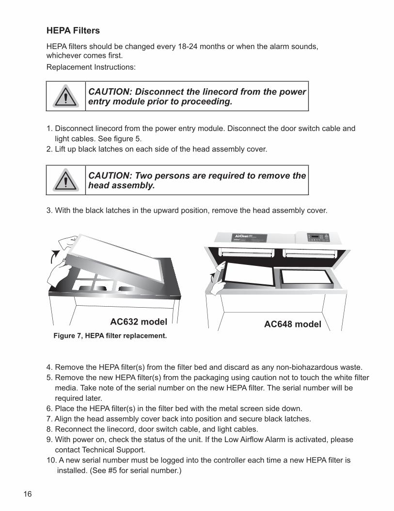
HEPA Filters HEPA filters should be changed every 18-24 months or when the alarm sounds, whichever comes first. Replacement Instructions:
1. Disconnect linecord from the power entry module. Disconnect the door switch cable and light cables. See figure 5. 2. Lift up black latches on each side of the head assembly cover.
3. With the black latches in the upward position, remove the head assembly cover.
4. Remove the HEPA filter(s) from the filter bed and discard as any non-biohazardous waste. 5. Remove the new HEPA filter(s) from the packaging using caution not to touch the white filter media. Take note of the serial number on the new HEPA filter. The serial number will be required later. 6. Place the HEPA filter(s) in the filter bed with the metal screen side down. 7. Align the head assembly cover back into position and secure black latches. 8. Reconnect the linecord, door switch cable, and light cables. 9. With power on, check the status of the unit. If the Low Airflow Alarm is activated, please contact Technical Support. 10. A new serial number must be logged into the controller each time a new HEPA filter is installed. (See #5 for serial number.)
CAUTION: Disconnect the linecord from the power entry module prior to proceeding.
CAUTION: Two persons are required to remove the head assembly.
Figure 7, HEPA filter replacement.
AC632 model AC648 model

17
To enter a new serial number: • Press the “MODE” up arrow key until the filter screen is displayed. This screen will display the days remaining for filter life. • Press the “SELECT” up arrow key. The first 2 digits of the old filter serial number will be blinking. • Using the “SET” keys, enter the new serial number starting with the first two digits. Press the “SELECT” up arrow key to move to the next set of digits. • Repeat until the entire serial number is entered. • Press the “SELECT” up arrow key until the “<” carat symbol is blinking. • Finish by pressing the “SET” up arrow key once to reset the filter serial number.
BULBS Fluorescent Bulbs The AC632LFUVC workstation contains one fluorescent bulb, and the AC648LFUVC workstation contains two fluorescent bulbs. They may be replaced as needed with a 15W Cool White Bulb. To replace the fluorescent light bulb in the AC632 model:
1. Turn off the power at the power entry module. See figure 5. 2. Completely open the folding front sash by carefully resting it on the head assembly of the workstation. See figure 8. 3. Using both hands, turn the bulb counter clockwise ¼ of a turn and remove from the light socket. 4. Install new bulb by sliding into the light socket and turning clockwise ¼ of a turn until the bulb locks into place. 5. Turn the power back on at the power entry module. See figure 5.
Figure 8, Fluorescent bulb replacement.
AC632 modelAC648 model
CAUTION: Disconnect the linecord from the power entry module prior to proceeding.

18
To replace the fluorescent light bulb in the AC648 model:
1. Disconnect linecord from the power entry module. Disconnect the door switch cable and light cables. See figure 5. 2. Lift up black latches on each side of the head assembly cover.
3. With the black latches in the upward position, remove the head assembly cover. See figure 8. 4. Using both hands, turn the bulb counter clockwise ¼ of a turn and remove the bulb from the socket. 5. Install new bulb by sliding into the light socket and turning it clockwise ¼ of a turn until the bulb locks into place. 6. Align the head assembly cover back into position and secure black latches. 7. Reconnect the linecord, door switch cable, and light cables.
UV Bulbs Each UV bulb has a life expectancy of 1000 bulb hours. The UVTect™ Controller will track the remaining UV bulb hours. Each time the UV bulb is illuminated, a minimum of one hour will be used. The alarm will sound when 100 UV bulb hours remain. When the life of the UV bulb has expired, the UV light will not work until a new bulb is installed.
To replace the UV light bulb(s) in the AC632 or AC648 models: 1. Turn off the power at the power entry module. See figure 5. 2. Completely open the folding front sash by carefully resting on the head assembly of the workstation. 3. Using both hands, turn the bulb counter clockwise ¼ of a turn and remove the light socket. 4. Take note of the serial number on the sleeve of the new bulb prior to installing. Install new bulb by sliding into the light socket and turning clockwise ¼ of a turn until the bulb locks into place. 5. Turn the power back on at the power entry module. See figure 5.
CAUTION: Disconnect the linecord from the power entry module prior to proceeding.
CAUTION: Two persons are required to remove the head assembly.
CAUTION: Disconnect the linecord from the power entry module prior to proceeding.
19
To enter serial number of new UV bulb: 1. Press the “MODE” arrow keys until the UV Lamp screen is displayed. This screen will display the number of remaining useful hours for the UV bulb. 2. Press the “SELECT” up arrow key. 3. Using the “SET” keys, enter the new serial number starting with the first two digits. Press the “SELECT” up arrow key to move to the next set of digits. 4. Repeat until the entire serial number is entered. 5. Press the “SELECT” up arrow key until the “<” carat key blinks. 6. Finish by pressing the “SET” up arrow key once to reset the UV light screen.
CONTROLLER
Controller Replacement for AC632 Model Workstation Removal 1. Remove the linecord from the power entry module as shown in figure 5.
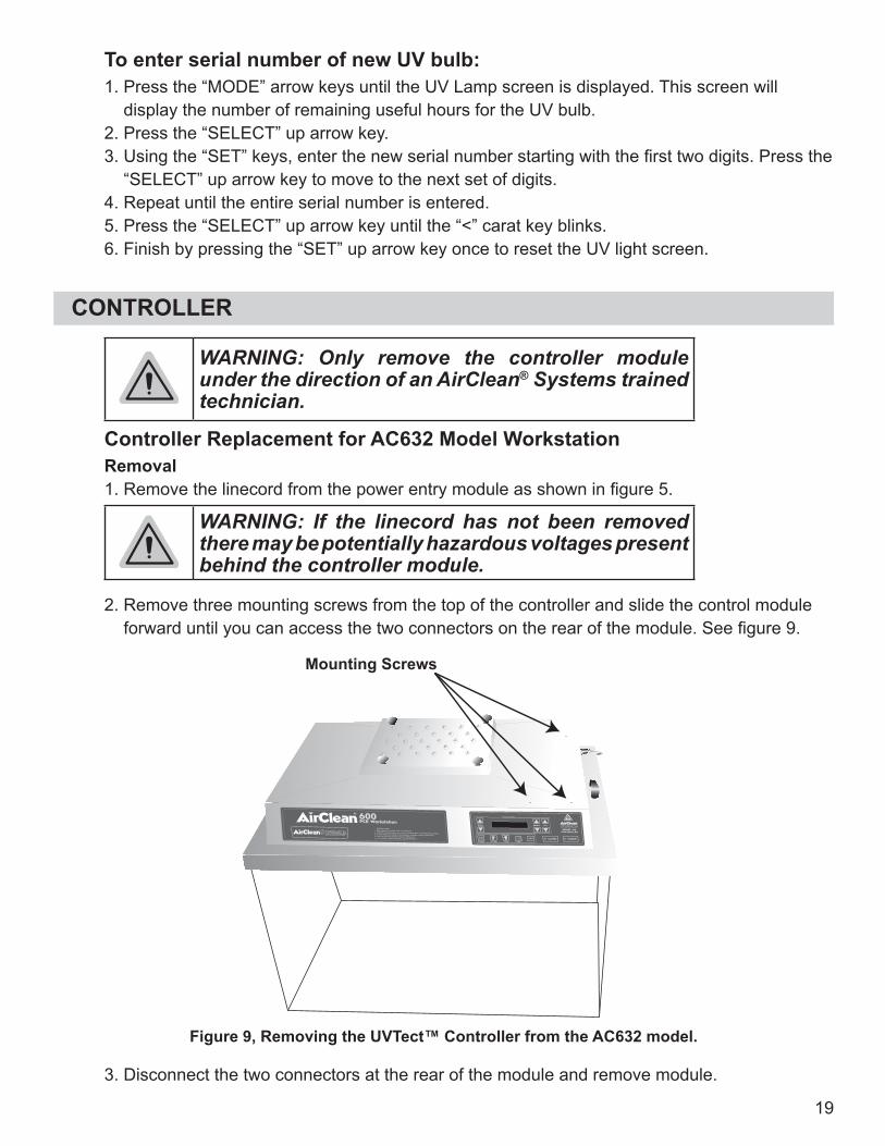
2. Remove three mounting screws from the top of the controller and slide the control module forward until you can access the two connectors on the rear of the module. See figure 9.
WARNING: Only remove the controller module under the direction of an AirClean® Systems trained technician.
WARNING: If the linecord has not been removed there may be potentially hazardous voltages present behind the controller module.
3. Disconnect the two connectors at the rear of the module and remove module.
Figure 9, Removing the UVTect™ Controller from the AC632 model.
Mounting Screws

20
Replacement
4. Place the new control module so that the left rear corner is in the control box opening. 5. Reattach the two connectors at the rear of the control box. 6. Slide the module into position and replace the three mounting screws. 7. Reattach the linecord as shown in figure 5.
Controller Replacement for AC648 Model Workstation
Removal 1. Remove the linecord from the power entry module as shown in figure 5.
2. Remove two mounting screws from the front of the controller and slide the control module forward until you can access the two connectors on the rear of the module. See figure 10. 3. Disconnect the two connectors at the rear of the module and remove module. Replacement
4. Place the new controller so that the left rear corner is in the mounting opening and reattach the two connectors. 5. Slide the module into position and replace the two mounting screws. 6. Reattach the linecord as shown in figure 5.
WARNING: If the linecord has not been removed there may be potentially hazardous voltages present behind the controller module.
WARNING: If the linecord has not been removed there may be potentially hazardous voltages present behind the controller module.
WARNING: If the linecord has not been removed there may be potentially hazardous voltages present behind the controller module.
Figure 10, Removing the UVTect™ controller from the AC648 model.
Mounting Screws
21
CLEANING
Exterior: • Clean with only a soft, damp cotton cloth or an acrylic cleaner. Do not use paper products to clean unit, as they may scratch the material.
Interior: • A high level disinfectant or 10% bleach/water solution may be used as needed. Sporicidin® is an approved disinfectant for use with AirClean® Systems PCR workstations.
WARNING: Interior cleaning with an approved disinfectant should be completed routinely. Residual moisture must be removed or UV radiation may cause chemical burn of the polycarbonate. If this occurs contact AirClean® Systems technical support before continued usage of product.

22
CATALOG NO. DESCRIPTION AC632 AC64812-51601 Electronics Box 1 N/A12-51602 Electronics Box N/A 111-50917 Controller Touch Pad 1 110-50055 Power Inlet Fuse, 3.15 A, Slow Blow 1 N/A10-50428 Power Inlet Fuse, 6.3 A, Slow Blow N/A 103-50184 IEC Connector 1 108-50221 Pressure Switch 1 106-50319 Swell Latch 2 210-50223 Door Switch 1 110-50199 Light Fixture 2 401-50396 Power Cord 1 110-50069 Blower 1 210-50070 Start Capacitor 1 212-50586 Aluminum Blower Support 1 206-50497 ¼-20 x ⅝ FH bolt for filter grid 4 606-50031 ¼-20 x 1 PH bolt for fixed sash 4 406-50547 ¼-20 Lock nut 4 406-50318 Sash Hinges 4 812-63285 Lexan™ Front Sash, Complete 1 N/A12-64897 Lexan™ Front Sash, Complete N/A 113-50827 Lexan™ shell 1 N/A13-50826 Lexan™ shell N/A 112-63281 Polypropylene Base 1 N/A12-64887 Polypropylene Base N/A 113-51600 Lexan™ Sash Rails 2 202-50139 Filter Grid 1 N/A02-51285 Filter Grid N/A 102-50650 Blower Plenum 1 N/A02-51024 Blower Plenum N/A 102-51505 Head Assembly 1 N/A02-51297 Head Assembly N/A 112-63271 Pre-filter Cover 1 N/A12-64879 Pre-filter Plate N/A 206-50422 Knurled Knobs for Pre-filter Cover 4 N/A10-50215 15W Cool White Fluorescent Lamp 1 2ACAUVBL4 UV Lamp 1 2ACFLFPRE Pre-filter 632 1 N/AACFLFPRE-7 Pre-filter 648 N/A 2ACFHEPA HEPA Filter 632 1 N/AACFHEPA-18 HEPA Filter 648 N/A 2
SPARE PARTS LIST

23
AirClean® Systems is committed to providing our customers with quality equipment and service after the sale. We, therefore, request that you take a moment to fill out the Warranty Registration Card so that we may know your location as well as some of the reasons that prompted you to purchase our product. To activate the limited warranty on your product, please complete the Warranty Registration Card attached with your shipment, and return to AirClean® Systems.
AirClean® Systems provides a warranty on all parts and factory workmanship. The warranty includes areas of defective material and workmanship, provided such defect results from normal and proper use of the equipment.
The warranty for all AirClean® Systems products will expire one year from date of shipment fromAirClean® Systems, except the following:
• DrySafe™ Forensic Evidence Drying Cabinets carry a two-year warranty from date of shipment. • CyanoSafe™ Cyanoacrylate Fuming Chambers carry a two-year warranty from date of shipment.
This limited warranty covers parts and labor, but not transportation and insurance charges. In the event of a warranty claim, contact AirClean® Systems or the dealer who sold you the product. If the cause is determined to be a manufacturing fault, the dealer or AirClean® Systems will repair or replace all defective parts to restore the unit to operation. Under no circumstances shall AirClean® Systems be liable for indirect, consequential, or special damages of any kind. This statement may be altered by a specific published amendment. No individual has authorization to alter the provisions of this warranty policy or its amendments. Lamps and filters are not covered by this warranty. Damage due to accidental breakage is also not covered.
NOTE: Do not return any materials without authorization from AirClean® Systems. Products returned without prior authorization will not be accepted. AirClean® Systems and its dealers are not responsible for shipping damage. The recipient must file claims directly with the freight carrier. If authorization has been received to return this product, by accepting this approval, the user assumes all responsibility and liability for biological and chemical decontamination and cleansing. AirClean® Systems reserves the right to refuse delivery of any products which do not appear to have been properly cleaned and/or decontaminated prior to return. Please see additional Shipping Claims on Page 24.
IMPORTANT: Locate Warranty Registration Card. Complete and return to activate the warranty on the workstation.
WARRANTY

24
AIRCLEAN® SYSTEMS CART ASSEMBLY INSTRUCTIONSModel ACA1011 and ACA1039
Your AirClean® Systems Cart is shipped with the following components:4 - Cross pieces 12 - 1¼” washers (hood bolt and cross piece washers)2 - End pieces 4 - 2 ½” x ¼” flat head bolts (hood bolts)4 - 1 ¼” washers (hood bolt washers) 4 - Casters8 - 2” x ¼” Phillips head bolts (cross piece bolts) 4 - Wing Nuts
ASSEMBLY OF CART
1. Locate a cart end piece and one cart cross piece. Place one 1¼” washer on to a 2” phillips head bolt. 2. Starting with hole one on the cart end piece place washer and bolt through the hole and into the threaded receiver of the cart cross piece. Hand-tighten only until cart is completely assembled. 3. Repeat steps above for holes 2 and 3. 4. For standard setup complete assembly using hole 4. For seated use complete assembly using hole 5. 5. Tighten all bolts completely. 6. Installation of casters should be per illustration on page 25.
MOUNTING OF WORKSTATION TO ASSEMBLED CART
1. Place workstation on assembled cart with front of workstation and locking casters on the same side. 2. Locate threaded inserts in base of workstation. Align inserts with mounting holes located on the top of the cart end pieces. 3. Place one of the 1¼” washers on each 2½” flat head bolt with wingnut. 4. Insert bolt, wingnut and washer into mounting holes on cart and into the threaded receiver in the base of the workstation. Hand-tighten only. Tighten wingnut, hand tighten only. 5. Repeat this process for all four mounting inserts.
Note: DO NOT OVER-TIGHTEN! Over-tightening will pull the threaded inserts out of the polypropylene base.
OPTIONS

25
2 - Cart End Piece
4 - Cart Cross Piece
2 - Locking Caster2 - Standard Caster
8 - 1¼” Washer
4 - 2 ½” Bolt 8 - 2” x ¼” Bolt
Standard Setup For Seated Use
Mounting Holes
Hole 3
Hole 5
Hole 4
Hole 1 Hole 2
ASSEMBLED CART CONFIGURATIONS
CART COMPONENTS
TOP
BOTTOM
26
If a shipment is received with visible damage, be certain to make a notation on the delivering carrier’s receipt and have their agent confirm the damage on your receipt. Otherwise, the damage claim may be refused.
If concealed damage or pilferage is discovered, notify the carrier immediately and retain the entire shipment intact for inspection. Interstate Commerce Commission rules require that the claim be filed with the carrier within 15 days of delivery.
NOTE: Do not return any materials without authorization from AirClean® Systems. Products returned without prior authorization will not be accepted. AirClean® Systems and its dealers are not responsible for shipping damage. The recipient must file claims directly with the freight carrier. If authorization has been received to return this product, by accepting this approval, the user assumes all responsibility and liability for biological and chemical decontamination and cleansing. AirClean® Systems reserves the right to refuse delivery of any products which do not appear to have been properly cleaned and/or decontaminated prior to return.
SHIPPING CLAIMS

27
If you have any questions that are not addressed in this manual, or if you need technical assistance, please contact AirClean® Systems at 800-849-0472, between the hours of 8:00 AM and 5:00 PM EST.
AirClean® Systems mailing address:
AirClean® Systems 3248 Lake Woodard DriveRaleigh, NC 27604
Phone: 919-255-3220Toll Free: 800-849-0472Fax: 919-255-6120
Visit AirClean® Systems on the Internet at: http://www.aircleansystems.com
Email AirClean® Systems at: [email protected]
MODEL NO. SERIAL NO.
□ AC632LFUVC AC632-LFUVC_______
□ AC632TLFUVC AC632T-LFUVC_______
□ AC648LFUVC AC648-LFUVC_______
□ AC648TLFUVC AC648T-LFUVC_______
CONTACT INFORMATION
Raleigh, NC 27604Phone: 919-255-3220 Toll Free: 800-849-0472 Fax:919-255-6120
Email: [email protected]
* Product designs are subject to change without notice. © 2006 AirClean® SystemsDoc. 57880 Rev. 4