59-553 graphical presentation - university of...
TRANSCRIPT

59-553 168
One of the most important aspects of the data reporting process (i.e. publication or presentation) is the graphical presentation of your results. There are numerous software packages that may be used to generate informative and attractive drawings of your molecules including: ORTEP-3 (sometimes in combination with POV-ray), SHELXP (XP), Diamond, and many others. I suggest that you examine a few different applications and become comfortable with at least a few of them.
Graphical Presentation

59-553 169 Graphical Presentation

59-553 170 Graphical Presentation Regardless of the type of picture you want to make, remember that the primary goal is to convey some sort of information! In this light, it is often wise to change the representations of atoms or bonds that are unnecessary so as to offer a clear view of the important features of the structure. You know the chemistry your structure is helping to explain so you are the best judge of how the information should be presented.
Remember that sometimes key information is provided by the packing and other interactions are important so you should always look at extended views of the structure.
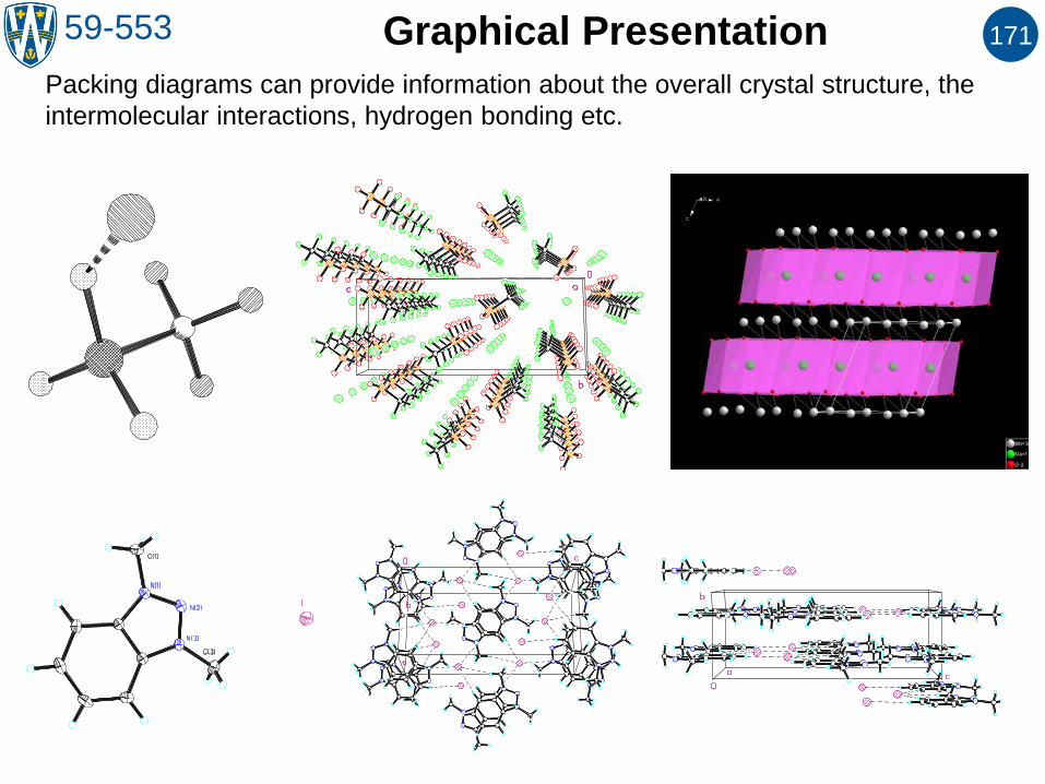
59-553 171 Graphical Presentation Packing diagrams can provide information about the overall crystal structure, the intermolecular interactions, hydrogen bonding etc.

59-553 172 Disorder One of the most common “problems” you may encounter during the refinement of a crystal structure is disorder. In general, “disorder” implies that the arrangement (or identity) of the atoms is not the same for every unit cell in the crystal. Remember that since each structure factor is determined by the entire contents of the unit cell, disorder in any part of the model affects the quality of the entire model!
Disorder can be considered in two major (sometimes related) types: Positional disorder – the arrangement of groups of atoms in the model are different (as illustrated at right). Occupational disorder – the atoms, ions, or molecules are not the same in every unit cell. This is common in minerals where e.g. a site can be occupied by various types of cations.

59-553 173
Such models are accomplished using the free variables and PART commands in SHELX. Sometimes you will also want to use the EADP command to constrain the thermal ellipsoids to be equal for the equivalent atoms in both models. EADP C11 C21 EADP C12 C22 EADP C13 C23 …. FVAR ..... 0.75 …. PART 1 C11 1 ..... ..... ..... 21.000 … C12 1 ..... ..... ..... 21.000 … C13 1 ..... ..... ..... 21.000 … PART 2 C21 1 ..... ..... ..... -21.000 … C22 1 ..... ..... ..... -21.000 … C23 1 ..... ..... ..... -21.000 … PART 0 ….
Disorder Most disorder is easily handled during the refinement by refining both of the disordered components separately with the requirement that the sum of the individual components is 1. E.g. if you model a disordered tBu group with two parts, the total contribution from each part must add up to unity (there must be a total of one tBu group).
Free variable 2 (FV 2) with a starting value of 0.75
With this value for FV 2, this position is modeled as 75% occupied.
The “-2” implies (1-FV 2) so this arrangement will be treated as 25% occupied.
The PART instructions tell the software not to connect the atoms from the different parts.

59-553 174
In this structure, the molecule can sit in two different orientations and still occupy the same volume and roughly the same shape of space in the lattice. In this case, the major component (drawn with dark lines) is found around 75% of the time: FVAR 0.25983 0.75266
Disorder Sometimes an entire molecule can pack itself effectively in more than one way. This can be considered as a form of occupational disorder. The more commonly found occupation disorder occurs because different simple cations (e.g. Na or K) can occupy the same type of site in many types of crystals. Such disorder can also be modeled using free variables with appropriate PART, EADP, EXYZ (equivalent xyz positions) and other commands. See the online SHELX manual for more complete descriptions of these commands and their use.

59-553 175 Twinning Another common problem you may encounter is known as twinning, which occurs when two (or more) lattices grow together in an oriented manner. Macroscopic twinning is generally observable when the crystals are examined under a microscope, especially if it is equipped with polarizers. Examples of obviously twinned crystals are shown below. This is called “non-merohedral” twinning and can be solved with CELLNOW or, sometimes, a decent single crystal can be obtained by cutting away the twin.
More problematic forms of twinning are often not observable by optical methods but become apparent in the solution or refinement of the structure. Such twins are “generated” by the presence of symmetry elements that are not part of the true space group – in reality the crystals grow the way they want to and we classify them based on the relationship between the lattices. These types of twinning include merohedral twinning, pseudo-merohedral twinning, reticular twinning, pseudo-reticular twinning and, again, non-merohedral twinning. Each of these types of twinning are described at the web site: http://www.lcm3b.uhp-nancy.fr/mathcryst/twins.htm (from which I obtained the diagrams on the following pages) and some methods that are used to solve such problems are found at: http://shelx.uni-ac.gwdg.de/~rherbst/twin.html. “Merohedral” indicates the presence of symmetry that is not that of the lattice.

59-553 176
In merohedral twins, the real and reciprocal lattices of both components are coincident. This type of twinning is easily handled by SHELX.
Merohedral Twinning
Projection along [010] of a monoclinic Pm structure (lattice point symmetry 2/m) with an object with point symmetry 2mm at the origin. The symmetry of the motif is only m
Effect of the axis 2[010] as twin element: the motif is repeated in the same positions but with a different, non-equivalent orientation (two rotated copies of the same motif are shown superposed in the projection).

59-553 177
Pseudo-merohedral generally occurs when the metrical parameters of a lower symmetry unit cell are similar to those of a higher symmetry cell. E.g. if a monoclinic cell has β ≈ 90º it can emulate an orthorhombic cell, if it has β ≈ 120º it can emulate a trigonal cell.
Pseudo-merohedral Twinning
In this picture the angle β is not drawn close to 90º to highlight the difference between the orientation of the black lattice and the red lattice. If the angles are close to 90º, the two lattices would nearly coincide. This type of twinning is easily handled in SHELX.

59-553 178
In this type of twinning, the two different lattices (red and black) are arranged such that some of the lattice points (shown in blue) end up being common to both of the component lattices. This situation ends up producing a “supercell” shown in blue. Note that, in this case, since every third lattice point ends up being common the overall structure is described as having a twin index of 3. Such indices are only used for this type of twinning.
Twinning by Reticular Merohedry
59-553 179
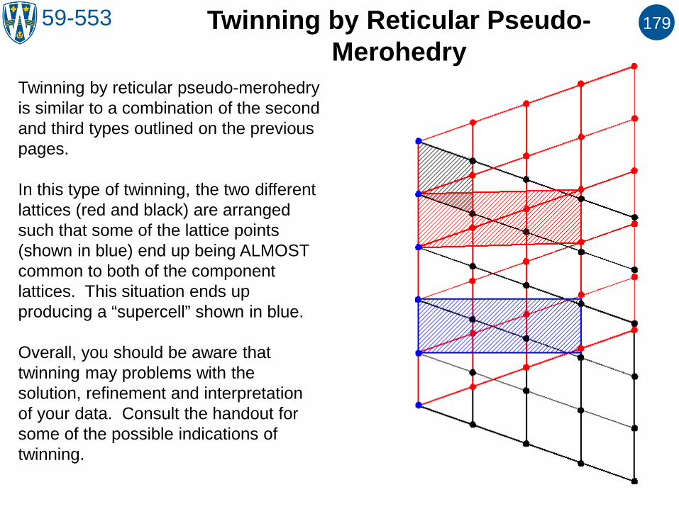
Twinning by reticular pseudo-merohedry is similar to a combination of the second and third types outlined on the previous pages. In this type of twinning, the two different lattices (red and black) are arranged such that some of the lattice points (shown in blue) end up being ALMOST common to both of the component lattices. This situation ends up producing a “supercell” shown in blue. Overall, you should be aware that twinning may problems with the solution, refinement and interpretation of your data. Consult the handout for some of the possible indications of twinning.
Twinning by Reticular Pseudo-Merohedry

59-553 180 Anomalous Scattering and Absolute Configuration
X-ray crystallography can be used to determine the absolute configuration of chiral molecules when they crystallize in non-centrosymmetric space groups. To understand how this is done, we must look at the effect of “anomalous scattering” on the structure factors.
The scattering that we have considered to date is “normal” elastic scattering.
“Anomalous” scattering refers to elastic scattering events that are delayed because of absorption by the atoms.
While this effect is not observable in centro-symmetric system (where Fhkl is only on the real axis), it has an effect on non-centric systems.

59-553 181
While this effect is not observable in centro-symmetric system (where Fhkl is only on the real axis), it has an effect on non-centric systems: Friedel’s Law is no longer valid. Since the anomalous scattering involves a delay, one can consider that the phase shift associated with this (shown with the red vectors) event will be in the same “direction” (the angle between the scattering vector and the anomalous scattering vector is the same). Modern detectors are able to measure the difference in intensities between the reflections that would have been equal if Friedel’s law held. Note that in the past, anomalous scattering required the presence of heavy atoms, which are not required for most small molecules using the current technology. Using the Hamilton R factor approach, you would solve the structure (xyz) and solve the “inverted” structure (-x-y-z) and compare the R values for the solution. This approach is not particularly dependable and is not generally used at present.
Anomalous Scattering and Absolute Configuration

59-553 182
No anomalous scattering thus the intensities of the resultant structure factor are equivalent.
Anomalous scattering alters the intensities of the resultant structure factors.
Anomalous Scattering and Absolute Configuration
59-553 183
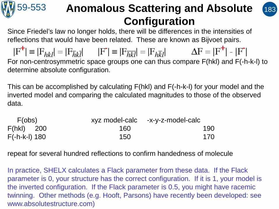
Since Friedel’s law no longer holds, there will be differences in the intensities of reflections that would have been related. These are known as Bijvoet pairs.
For non-centrosymmetric space groups one can thus compare F(hkl) and F(-h-k-l) to determine absolute configuration. This can be accomplished by calculating F(hkl) and F(-h-k-l) for your model and the inverted model and comparing the calculated magnitudes to those of the observed data. F(obs) xyz model-calc -x-y-z-model-calc F(hkl) 200 160 190 F(-h-k-l) 180 150 170 repeat for several hundred reflections to confirm handedness of molecule In practice, SHELX calculates a Flack parameter from these data. If the Flack parameter is 0, your structure has the correct configuration. If it is 1, your model is the inverted configuration. If the Flack parameter is 0.5, you might have racemic twinning. Other methods (e.g. Hooft, Parsons) have recently been developed: see www.absolutestructure.com)
Anomalous Scattering and Absolute Configuration