59 - mdl 2179 trial docs bop installations ... 10 api rp 53, rl!colitfiiended ... qontrol (irm...
TRANSCRIPT

•
Recommended Practice for WeU~ .-Control Operations ..;
""-,,.-,
API RECOMMENDED PRACTICE 59 SECOND EDITION, MAY200tr ...
AMERICAN PETROLEUM INSTITUTE
Highly Confidential
Exhibit No. __
Worldwide Court Reporters. Inc.
OSE 126-004133

Highly Confidential OSE 126-004134

Recommended Practice for Weir' Control Operations .;' .... ~
Upstream Segment
API RECOMMENDED PRACTICE6S: . SECOND EDlTlON, MAY 200'&" "
.'- ::,,"
AMERICAN PETROLEUM INSTITUTE
Highly Confidential OSE 126-004135

FOREWORD
This pubticaiton is under jurisdiction of th~ American Petroleum Institute. Upstream Dqm1, ,:,; ment's Executive Connnittee on Drilling aDd Production 0penti0nS.
rmlling and well SC!lVice ImitWrOOuction "tell service, well workover, well completion, W:t4" plug and abanoolllDCnt} OpcratioDS arc beIng conduclCd with full regard for flCTSO~i!at¢:Q',' ." public safuty. and preservation of the environnient in such diverse conditi,Qn$ as ~~ ~i1es, wilderness areas, ocean plallblIl1ll, deepwa~ siles, bmren dt:serts;'WiIdliIl: r;etu¥W- mtd arctic ice packs. Recommendations presented in thi~ publieaiion lITe baself-uU",tAfusm8.nd widc-rangfug indu.~try experience. " '" .,' .
The goal of this voluntary recommended practice is to assi$! the oil ~~:1tUiUStrY in promoting pe:rson.m:l and public wet)', integrity orlbe drilling and.wen sCrvle¢i:qu.ipmenl, and preservation of the envlrornneot for land and marine drill~ ~weil:~,;ce operations. This ~ndcd ptactjq; i, published tp fae.the ~~i1ity of pr()vcn, sound engin~ng and operating practices. This publici!ii\!dgoes Jl9f ~t all of the operating practices that can be emplOyed 10 successrully i~lIIi1j1li1topenile welt control syslel!iS in drilling andwell service operations. Nor doestni,~lfuatlim imply that all of the pral:tices herein arc applicable to aU drilling and \\~#~hpcratiOllS. Drilling SAd wcll .. f\Civicc operations throughout the world varywide1y.a:te.kCplace ~ a wide r¢~ or~ and sw:face conditions. Practices atmle~~ll notnecessarily be ~ata sitimitr uperd.1.ion due 10 diffi:rent COII<Iiti!.Jtj!f; ?mclioe, ~i'rorth herein are ~ lIL~leiht accomplishing the job as dcscripOd; ~Idntaltcmative installatiolJ~'an4~.c~·may be uti!imd to 81lOOinplish the ~'~\W$; Individtuds and o~d(; u.~l'l8.~ reoom~ practices ~ catl~ 'thai Opemtions Il1\lSt coroplt~.re.q~ts of national, state, -or lOcal regul~s. t~Tt:qfiiremenls should bcfA!t<iewl!d IQdeterinine whether vio-lations may ocCur.' .' ' .... ~. ' .' " '
Users<)f1"~~io~~t furtb herein are reminded flla\~IY developing technoltlgy ~~I1Zii.d9i'I~1tecl operatiollS do not ~it compfete coverage of all operations and i!l.~ve,.~coiiunendll!ions presented:~;Ire not intended to inhibil developing tcclnft,~an~:~ipmcnt improvemcnts qr:ii.J1P¢4 operational procedures. These recommeri&d~ are not intended toobviid¢:tbe,J:ie¢ torqnalified engineering and opec>.l\~ anal}'Seii and sound judgmen~$to .whIiillilld where these recommended practices
, .• '. -ab9uld be Ulili=! to fn a~iJjc ~'~-;Uion. , , "' ,-- ' '-: -'";. ". ~~ ..
. ':tb\s: publicatiOn includes lIs~ ilt~ Vcms.8h1ill and should, whichever is deemed most applicable for the ~ific ~liOn. FoT~ puiposes oftbis publ:ication, the following definitions
, are appliCllbie: . ,." ". ,;. '.
Shall lndicat¢s that the Te~~ practicers) has universal applicability to that specific 1!Ctivity,
Should-Denotes a reoonunended practice(S) a) where a safe comparable alternati\'e practice(s} is available; b) thllt may be iropracti.cal under certain circumstances; or c) thai may be unnecessary under certain circumstances orapplications.
Changes in the uses of these verbs lITe not to be ejf~~ without risk of changing the intent of recommendations set forth herein.
Nothing~ntajned in any API plJblicatiQn is to be construed as granting any right, by impli. cation or otherwise, fur the manumcrurc, salc, or usc of aD)' method, apparatus, or product covered by letters patent. Neither shollld anything contained in the publication he construed as insuring anyone against liability for infringement of lettets patent.
This document was produced under API statKiardi7ation procedures that ensure appropriale notification and participation in the developmental process and is designated a.~ an API stan-
iii
Highly Confidential OSE126-004137

dard. Questionsconrernii:lg the interpretation of the conlen1 of this publication or cumments and queStions concerning the procedures under which this publication was developed should be directed.in wliting to the Diroctor of Standards. American Petrolcnm Institute. 1220 L .. Street. N.w., Washington, D.C 20005. Requests foq1ermission to reprodtree or trsnsIate~' ,0
or any pout ()f the material published .herein should also be addreSlitXl to 1he directm:, -:: .. ~~. '
OCIJCl"8.Uy. APT standards an: rcvi<:wcd and revised, Tcaffinncd. or withdrawn at l~~ ... ~'·· fIVe years. Anne-time extem;ion ofup to two yea.rsmay he added to this review ~(Slittus of the publication can be ascertained from the API Standards DeparIu:leiit. teleP&ne (202) 682-8000. A cala/og of API publications and maleriais U;, published,,~~4Y ~;~ qllarterlyby API, 1220L Street, N.W:, 'Mlshington, n.c. 20005..,' ,
Suggested revisions are invited. and should be submitted to the Stand~t\ild Publications Department, API, 1220 L Street. NW, Washington, DC..~ 2()()()5.~aPi.org.
- ,. - ~', ",~. -~--?;
';.,."-,
iv
Highly Confidential OSE 126-004138

CONTENTS
SCOPE .................................... ·.·,.·········.,···· . 1.1 Purposc .•............ , ................... -.........•...... ;~.: 1.2 BOP Installations ........................... , ........ .. 1.3 Operntions ......... " . . . . . . . . .. . . . . . .• . . . . . . .. 1 1.4 l'urtkring the UndeISlandiDg otWell C.onlrol, . . . . . . . . .... 1 1.5 l1eepWater........ ... .. .. . .. .. . .. . .... I
2 REFERENCES .................... , ..•........ ;~;.:::,:. " .... , .... , .... 1
2.1 Sbmd81ds .. , ......................... ">." .', ":".-
2.2 Other References ............. , ........ ,,::; . .......... " ... 1 . ............. 2
3 GLOSSARY FOR \VEll CONTP..QL ~~~; f:' ......... , ........... 2 3.1 De1initiuns ..................... :.;.,.,:: .... ,.... . ... ,.2 3.2 Acronyms and Abbreviations :·0._._ •... 0' ., .• • • • . . •••. 6
4 PRINCIPLES OF WELL ~V;-4.1 General.. ........ . 4.2 Conventions ... ' .• ~'+ ... 4.3 Primary Well COll.it()h~ ;.... . ....... 7 4.4 ~:low~Welf .. : .. ::·..... . .......... 7 4.5 Drilling qf'*»'~Fluid ..... .,... . .............. 9 4.6 In1lul<!le~.? :;; . .. .. .. .. . . .. . .. ............. 10
::~ ~t't!:;r:t~~:::::::::::. ,:::::::::::::::::::~~ .4"i- Welt~_erocedures. .... , ..... ,..... c ••••• ,." •.•..••.• , •.•• .14
":0' 4. rO ~thods Fur Circtilaling Kicks:.~C9nstant Dottom-Hole Pressure ........ ..l5 ·~::,4.l1 ·~..circulation Kill Melhodih ::;; ,} ," .. , . , ........................... 23
_c:ti~:-~~{:=~~i::::::::::::::::::::::::::::::::::;~ 4.14 DiverterSystems~iI_ ....... ; ............ ···· .. · .... ·······,31 4.15 WeIlCo~Wor~:';~" .................................... 31
CAUSBSOF~KS.:;:~·:,· ..................... , ................ , ........ 32 5.1 Co~.'Ncl;e~fura Kick ...................................... 32 5.2 Im;ulIlcienfil~tic Pressure •......................... , .......... 32 5.3 Drilling Tnto IItfAdjaoont Well ....................................... 33
6 WELL CONTROL WARNING SIGNALS ............ '" .................. .33 6.1 GerIem.l. .... ; ..................... , .............................. 33 6.2 Gain in Pit Volume ..................................... '" ......... 33 6.3 Increased Flow fromAnnulus .... ". " ............................... 33 6.4 V(llume (lfDrill.illg Fluid to Keep the Hole Full on !l Trip is Less
Than Calculated u:r Less Tbun Trip Dook Record . _ ..................... .33 6.5 Sudden Increase in Hit Penetration Rate ........ , •...... ' .....•.•.•..... 34 6.6 Change in Pump Speed or Prcss1:ll'c.. . . .. .. ... ............. . ......... 34 6.7 Flow After Pumps Stopped ......................................... .34 6.8 Gas-c\lt Drilling fluid ......................... , .................... .34 6.9 Liquid-cut Drill:ing 1'1uid ............... , ............................ 35
Highly Confidential OSE126-004139

CONTENTS
7 WELL PLANNING .......................................... , ... . . ;:~;: .. .;js . ..~5
8
7.1 Introduction ......................................... .. 7.2 Data Ava.lability and Gathering ........................ . 7.3 Shallow Flows.. . . .... . ... .. . . .. .. ... . .. .. . ... . 7.4 Casing .......... , ..... , ........ , ... , ...... , ... " 7.5 7.6 7.7 7.8 7.9 7.10 7.11 7.12 7.13 7.14 7.15
Cementing. .. . . .. .... . .. . .......... "....... . ... 37 Blowout PreVention Equipmcnl Scle.ction . .. . . .. ,', •.•• , :, .• , . , ..... , .37 Dril~ Fluid. . . . . . . .. . . . . . . . . . . .. . . . . . . . . . ............ 38 Servi~-e Operations. . .• . . .. . . . . . ... .. .. . . ............. .3 II Kick Response Plans. . . . . . • . • . . . . . . . . , ....•......... .39 Ri$cr Disconnect.. .. ... . . . . . • ~, .•................. .39 Simult~ons Operations .. . . . .. . ' ................. , .. .39 Logistics.. .. . . . . . . . .. . . . . . . ..: ........................ 39 Safety 8.tId Medical ......... " ... 40 COmlnuWcation .. , ....• ;;;~'. . . . .40 Training ana Insttucti911 ... ; :,~ >" .\ , ••• ; . . .. . . .. . .. . • .40
WELL CONTROL PRoca>0~~iSUJUlACE DlVERTIi.R ':: INSTALLATIONS ..•..• ·.·.~.!~\·; . .': ,,:,.............. , .. :,.,,',";.; .... :.... . .. 41
::; =:~;,r.~~r::::::::::: :;;, ... :?:':;::: :':~:'::::::::::: ::~ !:! ~;==~~::::::: :~:!;:':: ... :~::::::.::::::::::: :::!
9 .. ··OObIT~:P~URES--SURFACEB01'S. if. c' ........................ 42 .'f9}· PrCcki~:kSPilmnmg........... . ................................ 42
·······~~~~~~' ••• • ••••.••• · ••••• ···· •• ·.·.·E . - ~ -. .', '-'~-'-'"
)0 WELL CO~r: PitpcEi>lJlt158FOR SUBSEA BOPS .................... A6 10.1 ~;:';>" .. ;. '.~:! ' ., ...•.. , , .•... , ......•.....•............. , .. 46 10.2 Additionilt~~~ Unique to Subsea Operations .... , , . , ......... 46 10.3 Subsea Exi:q:itUIUafo Control Procedures ........... , ........ , ......... 46 lOA Special Subscii.l'1nccdurcs ............... , ........•........ , ......... 47
11 WELL CONTROL PROCEDURES-RECOMMENDED RIG PRAL'TIL"ES .. , ... 48 11.1 Well Control Sy~1em Equipment mstallation, , . , . . . . . . . . •. . ...•........ 48 11.2 Well Control EquipmentTnstaIlation Test ...... _ .... , .................. 49 11.3 Crew Drill~ ............. , .... , .. , ................. , .............. 49 U.4 Trip Tanks ................... ,,,,, ......... '.' .................... 50 11.5 Gas-CutDrilling Fluid ................... , .......................... .50 1 1.6 Trip Book .. , ....•...........•........ , .. , .... , ...•... , . , .•.... , .. 50 11.7 Pre·KiCk Information ............................................. .52 11.8 Minimize Time OUtof1heHole ..... , ..... " ...................... , .. 52 11.9 Trip Margin ....................... ,. ..... ,. ........................ 52 11.10 Short Trip , •. , , . , .. , ., , , , , .. , ..•.. , , , •.... , ... , , .... , ... , . ; , , . , .52 11.11 Rig Practices for Handling Pressure .. '" .............................. 54
Highly Confidential OSE 126-004140

CONTENTS
.;~~ 11.12 rug l'rl!Cliu:s fur Pipe Handling ............................... ::.; ·.~4 > 1 U 3 Drill Stem Tests. . .... . . . . .. . . . .. .. . . . . . ... . .. .. . .. . .. . • . .';.~.
..54 12 PROCEDURES FOR DEALING W1TII SPECIAL PROBLEMs .... 12.1 In1roducUon .................................. ::::~;, .. 12.2 12 . .3 12.4 12.5 12.6 12.7 12.8 12.9
pu)np Failure in a Kick Situation ... . Excessive Casing Pn:ssurc .................. .. Pipe Problems with a Well Kick ............ .. ProeOOUreli furGu Bubble Migralion .•.•.. ,.'~' Gas Influx In Cemenred Annulus ...... . Drill Stem. Testing .......... . Stripping Proredures .......... . BuDheading and Thp Kill MetOO~~ .
, .... 54 . .... .55
, ",.,: )~: ........ .55 .. :.;." .'. q ........ 56
;;.; ............... 59 .,:: ................. .59 ..................... 60
..................... 60 ..... ....... .. . .... 61
13 SLURRlES AND PLUGS TO DI\ALWi'l:fU,OST ClRCULATJ;ON .AlIQ:) ........•.. : .
~~:~:.~~.~~~~;:~:~<'\~: ::: : :: : ::: : ::: : ::>~~. ':;': : :~:,;L:! 13.2 Lost Cin:ulaliun •. ',., .. ~:> .................... , .. " . . .'0 ..••• :! .61 13.3 Underground llJpwOllf8".,. ": .: ......... " ....•• , ..••.. ',... .. ... 61
i;:: ~=~~:~:~;~::'::::::::::::: ::::;~, .... . ,i, ..... :::::::::::! APPENDIX AKJCKPRf.8suRE ANI) GRArn~ CALdiATlONS ........... 67 APPENDIX)3.WELi-<timRoL WORKSHEBTS< •• : •.•.• : ................... 77
"' .'"' . - -'c •. ,":"i.
Flgu~/:';;' ......... .
;:{t=;::~::~~~::::·::::::::::·::::::::·:::: ! 4.4 Equi~t ~""el1l'er~~~~ •.............•................... g
!:! ~:"';;~k'~~~~;, .. :<~::::::::::::::: ::::::::::.::::::::::: :'I~ 4.7 Equivalti#t~latlitg~ .......•................................ 13 4.t! Well C1osd4.~on an:k . . . . . . . . . . . . . . . . . . . . . . . . . . . . . . . . .. . ........ 14 4.9 Closed·InDriB~'PitllSun: ......................................... 14 4. to Gas Influx MigiatiiigUp The Hole. . .. . . . .. .. .. .. . .. . .. . . . .. . . . . .. .. . .. 15 4.11 Stah,ilited Pumping of A Kick. .. . . . .. .. .. . .. .. .. .. . .. . .. .. . . . .. . . .. .. 17 4.12 CaSing Pressure AlIdGas Volume Resulting From Using The Driller's Method. 19 4.13 Casing Pres~'\Il'e and Gas Volume Usingtbe DrilIer'sMeIhod ............... 20 4.14 Dri1\ Pipe J'resSllTe Schedule fur the Wait and Weight Method. . . . . . . . . . . . ... 21 4.15 'I}'pjcaJ Casing Prcs.'IllI'C Rc5ulting from Using Wait and Weight Method ...... 22 4.16 Drill Pipe Pressure Scbedule-0mcurnmtMethod ........................ 24 4.17 Typical Casing 1'resI.'\Il'e Resulting From Using Concutrent Method . . . . . . . . .. 25 4.1 R Example Of Approximate Cuing Pressures With Oiffi:rent Kill Methods .....• 27 4.19 Pres.'lIlIC Lo~s vcrsu.q Flow Rate .. . .. . ................................. 28 4.2<t Ptessure Loss through Clioke Line and Manifold W'rtb Choke Full Open ...... 29 ILl Loss ofEffective Drilling Fluid Densi1y Due to Gas Cl\t . . . . . . . . . . . . . . . . . .. 51 A.l Weight of a Gas Kick, 0.6 Gravity Gas .. , ............................ " 69 A2 Maximum Surface Pressure of A Zero Tn1GnsityGas Kick .................. 70
Highly Confidential OSE126-004141

CONTENTS
A.3 hew lOr Determining the Maximum Surface urC.asing Shoe Pressure while Killing a GIs Kicln .. ith & Constant ~ttQm-Holc I'rcssurc Mcth«\; .,.. .?L
Tables 1 L1 l.lx.aInpie Jionn from a Trip Book ..................... : .. ; ,,: •. : . .. 53 12.1 ImneatorS of POsSible Problems while Circulatihg Out a Kick;,.:.>. . ...... 57 13.1. Barili': SlurIYFormulations.................. ... . .,,;; ......... 62 13.2 Sluny Volumes. .. . . . . .. . .. .. . . . .. .. ... .. .. .. • .. .. .. .. . . . . 63 In Barile IWquired (API Barite Spt;cifie Gnlvity = 00):"" . ,.;; ...... " ...... 63 13.4 nieselOiI-lIentonite rmlling Jiluid Reactive ~;" ..•• : .. ; .. '.' ........... 63 13.5 Trial M~ Ratios for R<;active Sluc:i:f ~~~;; :~;~ ........•.......... 65 13.6 Materials Quantities for Mixing One n~pf~:llS Cement Slurry ...... 66
Highly Confidential OSE 126-004142

.----------------------------------~-----~----- -
Recommended Practice forWell Control Operations
1 Scope 1.1 PURPOSE
well control worksheets tor sttrfaee aad5l1bsea BOP lnstallalions IIl"tl included in Appendix ~:~i~ are included for completing and use of the ... dlt\)lltipl worksheets. Rec-
The prupose of these recommended pfai)tices i.~ to provide ommcildcd pnlcticcs set fQl1hk,~ ~i:ation arc coosid-information that C$ serve as a voluntlU'y industly guide for ered ~ate to) meet ~Specil'feil"wefl conditions. It is -saU: well control opt:1'ations. This publication is designed 10 recognl.red.1hall~ ,l!f\l ~llfucedun;s !hat can 00 uti-~e as a direct field aid in well control and as a teclmica1 li7.ed in w~1 control~rniiy titequallYII!> effective in meet-source for teaching well control principles. This publication ing the weIL,~ and promoting safety and establishes recomm~ operations to retain pressure COll- efficiency.:", ',.
Iml orlbe well !I1lderpre-kick oontlitions and ree()~ 1." "F'.'" TH-~E'~I' .. "i"" .T' HE UNDERStANDING OF practices to be utili7.eddluing a kick. It selVes as aC()IlJparrion ,Vf" <}; moo 10 API RP 53, Rl!COlItfIIended Practice Jor Blowout Preven-' -.t.: QONTROL (irm Etjltiptnent Systems Jor Drilling wells and API RJ> 64 ", DIltaiG ~'~n control kchnology and masons for the ICC-
Recomw:enried J'mcttce for DiVMfer S)wel1l$ Eq.~ and ~procedures are incluQed in Section 4, "Principles OperalUmS (reader should check. for the latest,edl1jon). RP 53;;iL ,;ofWcli Control." Section 4 WlIli ~ so it can 00 used III! ~ r~mmc~ pract~s for thoinstal~l! ~~.. ~ .i\c(:jil1ical base fori~pci:$nQnel in well control opertesll?g 01 eqUIpment tor ~ anticipated well co1lditI~_II*,l:. . .~. Appendix .\"~ ••. ~ spcQial prc8SllJ'C l\nd ~ce .and RP,64 establishes. rec~d ~:~;> pressure gradient ~ns' awt'exampies t() t\trther ~\ltllllllon, teslmg.. and. opreralltm of dIVe~ l!".1Il}d ~ emphasize the tec~s.8ll!l ~a1cuialiOns that can aid a wen dlSCUSSCS the speCIal Clrcumstaoocs of Im~~. floW control superVi!l6tUifuldersllmding well coolrol operations, from shallow gas fonnations.'~~' ~. -,
1.3 OPERATIONS
This publication was developed to enhance well control by proper pbmning and e:reculion and lhus avoid a ki.-ck. The pU.blication also deals with the eventuality that a well kick may occur and prcscll1s details for handling such a kiclc lISing basic control methods. Details ofthese basic control methods are presented fur both surface and subsea BOP stack lnstallalions. Suggested ~'lJlliiiUerdlioru; and modifications 10 lhe basic control methods, which may be dictated by special problems or well conditions, are also CO~'eIed Recommended
2.1 STANDARDS
Thc following !itandards contain prpvi~ions,wh.icll through rererence in tlris text, oonsti1llte provisiOns of this standard. AU sland.rus are subjeel 10 revision and usen; are eru.~ 10 investigate thtpossibility of applying the inost TeCl::nt roltions oftho standard~ indicated below;
API Spec 6A RP5Cl
RP5C7
RP7G RPIOB
RP13D
RP 13R-1
Wellheatj and C'hris/ma> ~? Equipment Recomme.nded Practice for Care and Use of C'u.ving ancI Tubing Ilecommended Practice jiJr Coiled Tubing Operations in Oil and Ga5 Well Services Drill Stem Design and Operatinl{ Limits Recommended Practice JOr Testing Weu Cements Rheology and lIydrauiics of Oil-WeJl Drilling Nuid. Standard Pmcedu1"i! jiJr rll-ld Tealing Water-based DriUing Fluids
Highly Confidential OSE 126-004143

2 API REcOf,lMENOED PRACTICE 59
R.P 13ll-2
Spec 16A RPl6Q
RP49
RP53
RPM
RPS05
ASTMJ
0-1418
Stando.7tl Procedure for Field Testirtg Oilba.waDrilllng Fluid. SpeciflClllionjor Drill Through Equipment Vesigfl, Selection, Operation ana MainteMnet'I>fMarirw Drilling Riser Sy"lem.< Recommended Practice jOr Drilling and Well Sen1cing Opn-atwns Involving Hj'timgen Sulfide Blowout Pm.-eniion Equipment Systems fin- Drilling Wells Recommended Prtwtice for Diverter Sys~ Equipment and Operations Rero"rtnended Practice jor Classification of Loc.miom for EJectriCAt InstaJl4tinrlS oj f'eJrozdm. Facilities
Practicl for Rubber and Rubber Lattices -Nomenclature
3.1.5 annulus friction pressure: Cin:ulating pressure loss inherent in the annulus between the drill string and cas' ing Of Open hole.
3.1.6 backpressure {casing presS,U ... ~hoke pressure): The pressure existing at the ~oo tli6 easing side oftbe drill stringlaunulus flow s~,. ' "
3.1.7 barite plu&:,A ~ ~~ of barite particles from a baril!: sllllTY ~~iti~~~bore \0 seal orr a pres. sured rone. .; ,;. "'" ",
3.1.8 barite ~ A~ture of barium sulfate. chemieals, and wa1el;oi:.iiuril denSily belween 18 and 22 pounds per gallon :(jbi~}:' •.
. a, 1.9 .,'~ A slang tenn 1D denote flowing by heads.
. 3.":.10' bf,Ii. tiPPle: A plece of pipe, wi!h inside diameter .:inur groi:tcr than the ROP hom, conTlCCtOO to the 10p of tJ» BoP or marine riser with a side iNtjet 1D direct the drilling i'lUidreturns 10 the shale$hak~W#psua1ly bas II second
. JiidifoutlellOrtbe fill-l!I1~cO~ NACE2 MROl-75 :::::::::::: f:~7;:; :::;::J.14Ii!t·i 1.11 bleeding: qml~ rel~'; of fluids from a
closed and ~~ tn(mier to reduce the pressure.
2.2 OTHER REFERENCES
IAOC3
3.1.12 blind ~ (b .. ht, master): Rams wlw>;e ends are nol,.~ to'~, against any drill pipe or casing. They seal ~ cadJ~crlo effectively tlo$C the hnlc.
3.1.13'::~ear nuns: Blind TJUTlswith a built-in cutting cdgli:~ MI.! shear tubulars tbatmay be in the bole. tblL~
. '. il-lowlng the bfmd rams to seal the bole. Used primatily in
3.1 DEFINITIONS .... , . " . f~a sys~. 3.1.1 abnormal ~;'Phre pressnre in excess 0",·,:3.1;14 blowout:Anuncontrolledflowofwellfluidi.andl that prcssu:ro tc!\llI1ing fromtbc hydrostatic pressure ,~. . Otforrnation TIuids from the well bore. by a \'erticar~ of water with salinity !lOfIIlQl.~~.tW 3.1.15 blowout preventer (BOP): A devi£e attached to !-'t:o~are-";( . '. ,... !hej;llt;iIlglIead lllalallows 1he w~n to be sealtxllo confine the
3.1.2: ~ulMOr: A pressure ves!iel' clwgedwiilh nitro.. wen fluids to the \'locH bore.
:genilr~'inert !lllS.and used to store ~.#li#a under 3.1.1 $ blowout preventer drill: A training procedure 1D " ~!brPperdlion of OOPs. ' • '. , dctcnninc that rig crews arc complct.;:ly familiar with COlTCct
1.1.3 8Onu .. preventer~ A device, whleb can seal opetating praeticesto be followed in the use ofblowo\ltpre-'lIfQUnd any object in the well bore or upon itself. Compres- venlion equipmenl A "dry run" ofblowoui prevtmlive action.
.hion of a rt:infurced elaslotoor packing eIeroonl by hydraulic 3.1.17 blowout preventer operating and control pressure effects the seal. system (closing untt): The assembly of pumpS, valves.
3.1.4 annulus; The.space between the drill siring and the linels, ac(:umuialors, and oiheri1ems necessary 10 open and inside diameter of the bole being drilled, the last string of cas- close the blowout preventer equipment
ingselin !he well, or !he marine riser. 3.1.18 blowout prevemer stack: ihe assembly of well
IASTM International. HiO Barr Hamor Orive. P.O. Box C700, West Cunsbohocken, Ph. 19428-2959, "';"'W.astm.org lNACE Inlematiuiwl. 1440 SoUlh Ctt!ek Drive, nnll5ton, T"XlII< 77084-4906, V,iv.'W.naoo.org Jlntcnmtional Association of Drilling CoottactOIB. P.O. Box 4287,
lfOlIS!On, TX 7nlo4287. www.iadc:org
control equipment including prcvcntcrs, spools, valves and nipples connected 1D the top of the wellhead
3.1.19 BOPE: An abbreviation for blowout prcvcntcr equipment.
3.1.20 BOP: An abbreviation for blowout pIeVeltter.
Highly Confidential OSE 126-004144

RECOMMENDED PAACTlCE FOR WELL CoNTROL OPERATIONs
3'.1.21 borehole pressure: Tolal prossure exerted in the 'o\rell bore by a column of fluid and/or backpressure imposed at the surface.
3.1.22 bottom-hole pressure: Depel)ding opon the context, either a pre5sun; exerted by a column of fluid cantained tn the well bore or the formation pressure at the depth of interest.
3.1.23 broaching: Venting of fluids to the surface Of to the seabed through channel.s external to the casing,
3.1.24 bullheadil1g: 1\ leon to denote pIMping inlQ eloscd-'in well withoutrctums.
3.1.25 easing pressure: See Backpressure.
3.1.3& cut drilling fluid: Well conlrol fluid. wllich bas been reduced Tn density or unit weight because of entrainment oflcss dcn.~ formation fluids or aU;,
3.1.37 dl!g8Sser: A vessel, wl:t,idl~~ure reduction amJIor inertia to separate en~gm;eslitlm the Uqum phases. .~..' .
3.1.38 disp~ent:,'Thc ,:u.~ ofsfccl in the tubulars and devices inse~~~'Ot:~~n from the well bore.
- -.~' •••• ', ••• >,
3.1.39 dlVer:ter:A.(k~ allached to too wellhend or marine riseTtJ);do&,elh!i*erJlcal accesS aJId direct flow into a line awayfmi"il,thc. ri~,
3.1AO'dN~~~tem: The assemblage of an annular ~~¥.}low control means, ventsystem cotBponen1s.
3.1.26 casing seat test: A procedure whereby the fur· IlI:Id C3Iilil.>l iYslem which facililates closure of the upward mation immediately below the ca.~ing shoe is subjected to a . .fliiwpaliiof the well fluid amlopcntng of the vent to the pressure equal to the pressure expected to be exerted later bY': :::,.~. a higher clrilling lluid density 0;" by the .um oJ Ii higher ¢;ill::' ". '.' .' .. ing tluiddensily and !)aekp1"essun;created bya kiele. " ··:~;,.41 drill pipe~tjlialv.:.Anessentially li11l-open-
.:< , i\!g V'<livelocated ofi~~ J1~~ ~adl! to match the 3.1.27 casing shoe: A tooljotntconnecUx,l to1he~~ .•.• drill pipe in use: This vai~ts used:~~lose otfilie chill pipe of a string. of casing designed to guide the casJn!paisl ill~; to prevent flow .. ~~: . -. laritics in tile Open hole; usually rounOOd,l\t.the"l:iq1J!?m in :'. , .. sbapeand OOlJ:lposedofdrilla1;Jlema!etWi··\}\ ..:,.: 3.1.42Drll~t"(DST): A test condUCted to deter-
'. '.' .....•. c. mi.ne~tion ~ rate and/or formatiOn pressure prior to 3.1.28 c;hoke: 1\ device with eitbJit~u~',>:ariabl~ ~~iliig't~welt aperture used to control the rate (!f~l?f1~14 and/or gas. . ..... '.' ... '.
3;1~c ~JiJl::atring float: A check valve Tn tIle drill string 3.1.29 choke ~ (~oImanifofd): The sy&- that-,ili. tluid to be pwupcd into the well but will pretem of val vetS, c~ ···aM pipMg ~-iXlD.lrol JIow~ from the ,. vent flow from the well through the drill pipe.
anmllus and reguI~ureljih the drill string/annulUs ~'i>_})3.1M drilling break: A chang\! in the nde ofpenel.nttion
system. . . " .. . . :. 'i' / tllat may or may not be a result of penetratinS a pressun;d res-3.1.30 chote line: Thehigh-prel$U1"e pipingbe1w~>0Crvoir. BOP outltl!Sijrwell~outlets and the chpke ItJllIJif.eIIL·
" '-. " ." '~,c. ;c:. ';' r, ~:-.: .. -'-~'~_"'_'
3;-u2 ·'·ciitculating head: A dcvk:iat\aCbcd~1hc top of drili~M tubbl@to allow pumping intb.~lt"· . . " .... : . >:
..•.. ·3.1.33 closing unH: The aSsembly of pumps. valVes, Jines, accumulators, and other items necessary to open and
. ".,close the BOP equipment,
3.1.34 condUctor casing or conductor pipe (onshore and bottO/JMiupported offshore instal1atlons): A relatively !iliort string oflargo diamctct pipe that is ~ to keep the top of the hole open lind provides means of returning the upward flowing drilling lluid from lh~ weU bon; to the surface driJlTng fluid system until the first casing string is set in the well
3.1.35 control panel, remote: 1\ panel containing It
S4;ries of oontrols that \\~ll ~1c the valves on the control manifold from a remote pOint.
3.1.45 drlllinlil spool: A flangedjoilllp1acedbctweenthe BOP lind casmg-bcad or between BOPs 1hat serve as a Bpa(:el"
3.1.4& drive pipe: 1\ relatively short striflg of I~ diam· eter pipe usuallysct in a drillod hole in oo.'Ihorc opcratioJl.<l; it is nonnally washed. drfI.-m, or forced tnto the ground in ootIum-supporled olI"shore operatioruo; sometimt:l; refemxl IQ >IIi
structural pipe.
3.1.47 dynamie well kin procedure: A plan.neQ opera· tion to control a flowS well by injecttng fluid of 11 sufficient dc:mrily and al a sufficient rdle into the well bore to eITecl.a kill Without complctefy closing tn the well wi1l1 the surface coota\nInl;nt equipment
3.1.48 Equlvalent Circulating Density (ECD): The sum of pressure exerted by hydrostatic .bead of flltid, drilled solidS. and fii~1ion pre8l>"\m: losses in the annulus divided by dI..,nh of in10rcst and by 0.052, if F.cn is to be expressed in pounds per gallon (tWgal).
Highly Confidential OSE 126-004145

4 API RECO~NDEO PRACTICE 59
3.1.49 final circulating pressure! Drill lI\ring pressure reqaired to cm:lIlate at the selected kill-rare IHljusted for incrCa$C in kill drilling tluid density over the original drilling fluid density; tIsed from the time kill drilling fluid reaches the bollQm of1he ~U ~tring until kill oper"d\ions an: compleled or a change in either kill drilling fluid density or. kill-rate is effected.
3.1.50 fluid density: The" unit weight of fluid; c.g., pounds per gallon (lbigal).
3.1.51 fonnation breakdown: An event occurring wbeu borehole pIeSSUreis ofmagnilUde that the expI)SCd formation accepts wbole Jluid from the borehole.
3.1.52 formation c;ompetency (fonnation integrity)': Tho ability of the formation to wlthstand applieli pressure.
3.1.65 H~: An abbrevUition Ib:r hydrogen sulfide.
3.1.66 hydrolPln sulfide: A higjlly to<cic. tlanunahle. corrosive, gas sometimes encountered iI:I~caxbon bear· ing fOrmations. '. . . . .
3.1.~7 hydrogen sulfide ser.nili:3tebJ ~ ~quipuwnt designed to resist corrosiona¢:~' embrittlement calLwd by cxJlOSUIC t()hydrop ~
3.1.68 hard Close;l,"Ho'~~iDa well by ck>siiig a ilOP with 1he cllo!<e~iii: clJQke iUIe valve closed
3.1.69 hyd~~a~'The true vertical length of f1uidOOIuinn, ~:y i(i feel
3.1.70~~·'Pressura (hydrostatic head): 'i'iJ,le ~~~t:xlsts llI.any point. in the w<:ll bore due 10
~''Y~i,g\tt{,ft¥vc:rtical column oft1uid abo"e that point.
3.1.53 formation competency test (formation ", .3.1:~1,1IJIi~x:The flow offlu~:from the fOrmatli:ln inttl Integrity test): Application of pressure by superimposingt\.:; '~·welltiore.
surface fIl"CSSurc on a fluid colunm in order to. determine ~ .• : 3':1.12 Initial clrculilting~$!i": Drill pipe preSsure itr of It subsUtiilce zone to withstand a certain ~ .. "':tl:quired to circulate lhi~"II11he .~ kill-raW: while pressure. holding easing ~ ~tIili1;li!seclffuvahre; numerically 3.1.54 formation fracture gradient: Tbe~ equal to kill-ratc c~p~pfus closcd-indrill pipe value expre~ in psilfi. that is required 10 ~ a~ pressure, ':", "'.
in a subsurface fOt'flUltion (geologic strata); .' . . 3.1.7~· ~pel'fOl!JYlance (IPR): represents tbe ability 3.1.55 formation integrity! St:eJ'~tibt,i.CbmpeIenCY. of a ~10 ~ fliiids and is typically representc.d by the
curVdilft\,p~,.otlIDwingprcssure VCl'SUS flow rate. 3.1.56 formation Integrity test:. Seel'QpnationCompe- , .;: .. teneyTest,:/; .'of /;': . 3.1.74~·BOP: A device that can be installed in 1he
·dtill string that acts 8ll a check valve aIlow:ing driUing fluid 10 3.1.57 formation~UI1J.tpore pressure}: PressufCe;~' ·.ht ciroulaiat down 1he ~tting but prevents back fiow. exerted by fluids wilhiA:iIie~ pC the formation (see Pure'" Pressure). ~ .' .~1;"5 kelly: Thcuppcrmost compollCllt of the drill string;
. the kelly is an extra-heavy joint of pip!: with flat Of fluted
3.1.~.~18 TJradient (frac w::sdient):'~iJlQiS\lJC ~(pSiIf!) at which 1he formatioJi~ ~ fluid
, Ii9mlM'Wcl1 bore.
";'3.1.60 gas buster: A ~. term to denote a mud: gas .. ~10l:
1;1.61 gas cut drilling lIuid: Drilling Fluid that bas become entrained wi1h gas from previously drilled g811 bearing furmatioo which in wm lowers the .drilling fluid density and hydrostatic head of the drilling fluid column.
3.1.62 gunk plUg: A volume ofgunk slunyplacedin the wellborc.
3.1.63 gunk slurry: A slang term to denote a mixture of dicscI oil and bentonite.
3.1.64 gunk squeeze: l'roccdnrc whereby a gunk slurry is pun1IIed into a subsurface moo.
sides thalis free to move vertically through a "kelly busbing" in the rotary table; the kelly bushing imparts \oTque 10 the kelly and thereby tiro drill string is rotated.
3.1.76 kelly cock: A valve inuncdiatcly above the kelly that can be closed to confine pressures inside the drill string.
3.1.77 kelly valve, lOwer: Iu1 cssenlially full-opening valve installed immediately below the kelly, with outside <!iamctcr equal to the tool joint out~idc diameter.
3.1.78 kick: lntfusion of tOrmation flwOs into the well bore.
3.1.79 kill drilling fluid density: The nnit weight, e:g., poUIld.~ per ~Ion (lbIgal), sciccted for the fluid to be lLo;cd ttl contaln a kicking furmation.
3.1.80 kill line.: The high-pressure piping between the pumps and DOP oullets or wellhead outlels.
3.1.81 kill-rate: A prcdctcnnincd fluid circulating rate. expressed in fluid volmne per unit time, which i~ 10 be u.'Ied to
Highly Confidential OSE 126-004146

RECOMMENDED F'AACTlCE FOR WELL CONTROl.. OPERATIONS
circulate under kick conditions. The kill-rale is usually some selected trACtion of the circulatingrale used whiledriJling.
3.1.82 kill-rate Circulating pressure: Pump pressure requiTed to circulate kill-Tate. volume under non-kick conditions,
3.1.83 leak-otr test: Application of pressure by superimposing a surface pressure on a fluid column in order t() deter· mme tlJe pressure at 'which the exposed fbhnation acCepfs wliolefluid
3.1.84 lost circulation (lost retums): The loss of whole dri1l.in$ fluid 10 the wcll bore.
3.1.85 lost re~ms: See Lost Circulation.
3.1.86 low choke pressure procedure: Consists of circulating and weighting lip the drilling fluid, both at the maximum rates, .... -hHe holding the maximllm allowable cas·' ing pressure un !he choke,'
3.1.96 primary wetl control: I'nlVention of wnmUion fluid flow by maintaining a hydrostatic pressure equal to DT grca1Cr than fonnation pressure,
3.1.97 ProductiVity 1nc,1ex (PI}::1IG:l~}CJll'CSCllt$ one point on an inflow performance ~W'J{}'aOO is defined as the well 1\ow in bturels pt'2'~Il)<P\lf ~1li.~ drop.
3.1.9& Remot~ Opiil'ated::VehICle (ROV): An unmanned vebicl: tbr})~~lIU~ use,
3.1.99 repla"41lmi~'flle process whereby Ii volume of auid equal19lhe' ~e;hr Steel in tubulars and tools withdTawn ftnm~;~~ isTe1urned to the well bore,
3. U~ .,,~ti" head or rotating drillIng head: A rotari~I6iV,~ sealing devicl: ,used ifldrillulg opera.
" ,:~,{,tftl!~' air; gas, N foam (or any other drilling fluid '",~bydiostatic pressure is ~ than the formation pres
.~un::'J1O seal around ihe drill sldn !!hove the top of ihe BOP ~k '.
3.1.87 lubrication: Alternately pumping a ~iycly;>, !:U01 rotating~/~: A sealing device small volume of fluid into a closed well bofll s~'~lld " installcdabovc thcJlOJtSliiiduscd tOlllosc the annwaupacc waiting for the fluid to fall toWllfli the bottom ,O!~. Wc.:U.'·· . about the drill ~" &-, ~iIy Wheti :Iiu!liug or nmning pipe
3.1.88 marine risorsystem: The. ,<., under~~ ,'<, bore from the subsea BOP stacIe to the tl U~~~'~ry~: A device through wbich pa$ses the which P«lvldc.~ fur fluid retuIns. to lbo, , sup- bi~iind ddtSlrlng 1itid that tnmsmilJl rotatioI)ll1 action to tbt ports the "hoke, kill, and COTI~li~~~ tools into the kelli.:.". well, and serves as a J1PlI1i. striti8;fDT~ BOP stack. 3.1~ 1~ Sldely factor: In the con~' uf IhispubU(.'lilion,
.u.89 mUd-ga$~~~;'or; AtJS.~1 for J"Cl1lQving fr(:O;< an intrememal in~ in drillhlg fluid density beyond the "1I$ from the dri"~ ..... "',.;rl retUttlll," ,. . ' .' ; i;r'tlt'ulill8 fluid density indicated by calculatiolls'tQ be ncc&.xi to ., ~....... .... . oontain a kicIcing fonnation. 3.1.90 n~a1 ~!PonnaLiOn pressure;:qulll~'r;i; the ~ ~ by avertical column ofwatdr'wtIhSa&:. .. 3.1.104 saltWater flow: An inflnx of fonnation saltwater ity II()nnaf~~ geographic area.. o.··..;~ i\ c", into. the well bon:.
3~~»t •••.. ~~nc:e: The 11IJIDimt. by' whick .~ 3.1.105 shale shaker: A vibrating Screen that n:movcs e~~~.;jhe hydrostatic beud of .1luii,J in Ilitii well bore relatively large size cuttings from the drilling fluid returns, eJt~ ~tion preSl>w:e. .:. : •. ;.
3.1.92 pack-off or stripper: A device with :m elastomer 'packing element that depends on pressure below the packing
' .. ":,10 eill:cl a seal in the annulus. Used primarily to ruu or pull pipe under low or mollemte pressures. This device is not dependable for service under bigh differential pressures,
3.1.93 pipe rams: Rams whose ends are contoured to seal around pipe to close the annular space. Sepatate Tams are 1)(CC;1I;sary for each. ~ (Olllside diameter) pipe in use.
3.1.94 pore pressure (f9rmation pressure): Prcsstlre exerted by the lluids wiLbin the ~ ~-pace of a funnation.
3.1.95 pressure gradient, normal: The normal pres. sure divIded by true vemcal depth.
3.1.106 shear rams: BOP rams with 8 buitt·in cutting edge that will SOOdI'tubulars that may be in the hole,
3.1.107 soft close-In: To CloSe-in II well by closing a OOP with the choke aruJ cboke line valve 0lJen, lhtm closing the choke while nlOtlitoTin!! the casing pressure gauge fur maximum aIlo:wable casing pressure,
3.1.108 sour gas: Natural gas .containing hydrogen sulfii\C,
3.1.109 space-out I'rocodw'C conducted to position a predetermined length of drill pipe above fhe rotary table so that a tool joint is located above the mbsea prevent« rams on whicb drill pipe is 10 he suspended (bung-oJi) and so that no tool joint is opposite a set of prcvcntcr rathS after drill pipe is 1nmg-off.
Highly Confidential OSE126-004147

6 API RecOM,MEfI!I)ED PRACTICE 59
3.1.110 spaceoOllt Joint: The joint of drill pipe used in bang oIT ope1"dOOns so 1hat no i0oi joint is opposIle a set of preventer rams,
3.1.111 squeezing: Pumping fluid mto one side of The drill pipeI[UlIlUlus flow system wi\h the other side closed 10 allow Do ouUlow,
3.1.112 stripping: A procodurc fot nwulng or flUlling pipe from the Well boll: with pressure in the annulus,
3.1.113 stroctul"l.'l casing: The outer .SIring of l~ dl.ameter. heavy-wall pipe installed in wetls drilled ti"om floating instaUatiollS to ~ the. bending moments imposed by the marine riser and to help support the wellhead instalkld on the oonductor casing.
3.2 ACRONYMS AND ABBREVIATIONS
TIx; following acronyt\'lS and abbreviations arc used in 1his publication: c
API AmericanPetroleumlnstiJuilt\'cc; BOP Blowout.Preventer '~;;. :": ~.~ ". lAOC InteJ:natiOnal Associa~ofbrilllng Contractms ill lru!ide Diameter :,":J . c ".
CD OUISi!.k:OiameIti' . psl pounds Pi:r.roiti¥;"
4 Principl~~i Wei';Control 4.1 GEN~/' ,.'
3.1.117 targebld: Refe~ to~fmij~~'Sys1ertl in 4.2 "COJweR1'tONS wtiicll flQW impinges 11pI,lll'4leadiitred eil4l~rget) or It piI>-" . ~ ~ ~_. ing lee wh!:n: fluid b"aIll;.'.:lI$,::~~~. ii(~. '~;1ion, Mostof'tliilfuou.Ilm,nt and the exampiesateMitteu wm a
"'.~ operatioDS perspective. The principles and procedures 3.1.118 trip gas:'M:at;c~n of gas, which cntcr~,,:,itllUs document cover other Q{JeI1IIiuIlS where well mnlm! tbebolcwbi1ea1ripis~;·. '. .. ,"'~p1es and practices are used such as completion, work·
',> " " ,-,:.~~i, well service, and plug and abandonment 3.1.119 trIp)ilargln: An increnlental increase\l\~litlJ fluid densitY ~~de an increment of ov~aoofin ~";. 4.2.1 Design for Specific Rig. Equipment, and to. co~ f<teffc'ctstlhwahbing. . ,. . Conditions
''". -+ 1.:u.o'tUbUlarS: Drill pipe, dril1.~ Iu~,and l1ic drilling, completion, worlCover, wen service, alld plug Cl!sinIf;~'c'? ' .• o'~/ and ababOOnin~nt OperatiollS i@. done wi1h a wide I,1IIJge of
, i rip, equipment, and in a variety of condlliOllS. The proce· .'.,'.11.121 underbalance: The amount by which fOl1lllltion dum; oonlaIDed herein an: uLa general nature and must be
. :~re exceeds pressure exerted by the hydrostatic bead of reviewed and modif'led for the specific rig, equipment, and IltOO in \he well bore, cooditiQllS cXfJC!:tcd ina particular ppcration.
3:i.122 underground blOwout: An unoontroUcd flow of fonnation fluids from a mbsurfacc zone into a !lCCo1ld !lUbsurface moe.
3.1.123 weight cut: The amoWll by which drilling fluid dcn.'lity is ICducOd by entrained formation fluids or alt.
3.1.124 wireline p.-.venters: Preventers installed on tOp of the well or drill sttillS as a precautionary measure While rutming wirelines. The preventer packing will close around the wireline-
4.2.2 Drill PipelTublng/Caslng
Unlesl; u1l)erwise noIetJ, the It:nn "drill pipe" can also apply to lilly siring of pipe being run in the hole whether it be drill pipe, drill oollars, tubing, casing, a liner, or coiled fubing.
4.2.3 DrillingIWo.rkover Fluid
Unless otlwIwise noted, lhe lellrl "drilling tluid" can also apply to "workovcr" or "completion" fluid. Oril1ing and workover fluids can be gas, liquid, or foam (reter to 4.5).
Highly Confidential OSE 126-004148
4.2.4 Circulation
Unle$!! othernise 11Oted, the ten11"circubttion" refers to conventional ciroulation, which is cm:ulating fluids down tbe mterior of a string of pipe in the well and up tho annulus. ReyetSe crrculation Is the opposite; fluid is circuia~ down the iIllnulus and up the pipe in the holo.
pa:rtiwlar /Urination in a well will llow. TW(} relationships 1'eQ1.1ire examinatiQn; well perfOrmance and equiproem perfonnance.
4.4.1 Welt Perfonnance
Flow rate versus preSS~i$~~through the Ilow path from the bottpm of~~~lIta,1tlc top. Well performance
4.3 PRIMARY WELL CONTROL Is independent otth;~,Ill<ldwnstmun of the point of
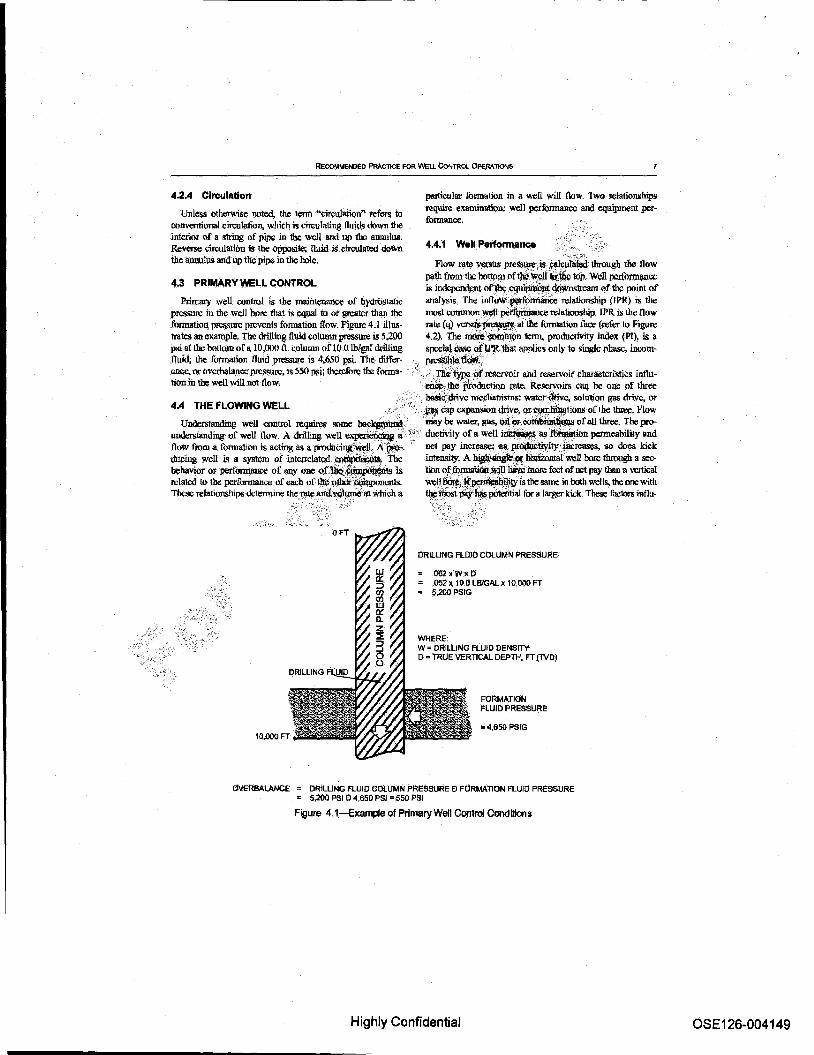
Primary well conllOl is the mamtemmce of hydrtlllwtlc anaJ}~s. The infloWIi¢Otmaoo: relationship (IPR) is tile presSUte in the well bore that is equal to or greater tlJan the most common ,~i pe~ relationship. IPR is the nuw formation pI'ClISUfC prcVqlts fonnation flow. Figure 4.1 ilIu.~- mil: (q) vc:rsr.ill~, Iii dJe formu.tiun face (refer to Figure trates an example~ The drilling fluid column pressure is 5,200 4.2). The ~4otn~ term. productivity fidex (PI), is a psi at the boUom oC a 10,000 1t column of 10.0 IbIgal drilling spccial~~~tliat applies only to single pha.~, incom-fluid; the fonnatto;, fluid pressure is 4,650 psI. The dilTet- '" ~tC:~:' em;c, or ovcrhalan.cc prc.'lSlm:, is 550 psij thcrcfurc the forma- -<> TIiii tY~ ~Ml'IlS<:f\'Oir and reservoir charaCteristics ioflutionln the well will notfluw·~,the~ction rate, Reservoirs eM be one of three
.- ", b.iSic:~drivc mechanisms: watct4nvc. solution gas drive, or 4.4 THE FLOWING WELL
Ur¢rstanding wellconttol teqJlires some ~. tmderslaruling· or well flow. A driIIing well ex.periein~ a' flow from a fomlation is acting as aprodncint~l, A pro." dueing well i~ 8 syl!lcm Qf in1Clfclatcd _ ~il. The behavior orperfonnance of any one Qftilii~~1S is related to the perflml1ll1lCe of each of tliej)lOOi:~Is. These telatiollshlps detennine the]~te arid vOIpniem which a
. "_~ Cap expanilion drive; o.r~ns of the Ilu:el:. Pluw may he w8Ier, gas, ¢lOroo~~ of all three. The productivity of a well i~ asfOim\ition permeability and net pay inCrea5I;; ~ pro(itctivity iDl:te~s, $0 does kick intensity. A~;oc ~twen bote through a reolion ofjpnnatioo .'ltjn~ lnore feet of oct pay than a vertical
wdl~l!~1~!yis the same in both "fells, the one with tbji-lilOsi ~-~ p(,teiitial for a l:uger kick:. These fuctQrs influ-
DRILLING FLUID COlUMN PRESSURE
.062xW:XD .052 x 10.0 LBIGAL x 10.000 FT ~.200 PSIG
WHERE: W = DRILLING FLUID DENSITY D = TRUE VERTICAl DEPTH. FT (1V~
FORMATION FLUID PRESSURE
=4.650PSIG
OVERBALANCE = DRILUNG flUID COlUMN pRESSURE £) FClRMATION FLUIO PRESSURE = 5,200 PSl £) 4,650 PSI = 550 PSI
Figure 4.1-Example of Primary Well Control Conditions
Highly Confidential OSE126-004149

8 Af't RECOMMENDED PRACTICE 59
ence the shape of the IPR .:urves fur particular _lis. The same is true for thee-quipment pc:rfrnmance curve. The size of the hole, the sID: of ca.~ and the sID: ofth<: tubular goods influence tb: shape 9f a particular equipment performance curve.
4.4.2 Equipment Performance
Flow rate versus pressure .is calculated at the p<>int of analy$ls (refer to Figure 4.3).
Every pOint on 111(: equipment perfonnanec curve is valid. However, the only valid value tor tb;l Well system is at the intersection of the IPR and equipinent perfonnance curve (refer to Hgure 4.4).
4.4,3 Conditions for Well Flow
If the equipment performance eurve for gastliquid flows in \he well bore does no! croliS \hi: well perfurmance j;urve (stayS to the right of it Tn the convention shown in example Figure 4.5), the woll will not flow. To kill a woll. the cq~ meni performance eurve must be designed to exceed thew(;lli .• ~" performanre curve. This is ca1k:d "dynamilO kill" This tiisi1iilt\, . the backprcssure that can be applied by the hydrQSiaiit; 1.e8d plus the hydtaulic friction ()f the fluid.~ in the ~ 1nu.~ . e.xceed the inflow performance relationship (~), .' "
4.4.4 AppliCiltion of Backpres$UI1II tQ;~nirol'W.1I Flow .'
Backprossure can 1J(;;,~ ~ •• ~.~ rate, drilling flUid density,. and 1tqw'teStnC~ nttbeequipment oown- , slrelUil of the formalj(jll:'.ilIL"e. Alt.of these t:n'tlClS should 00:7" co~idercd bUl the chOtt ~\i$¢ta adjust backpressure dur")· .. ing kill opcration.,. FoUowmgarelhrcc examples; C"
FloWing bottOm-hale pressure
-
~F~~4.slEquipment Petfonnance Relationship
. ft9ure 4.4-Equipment & Well Performance Curves
Pressure
Equipment performance
Figure 4.2-WeU Performance Figure 4.S--Oynamic Kill
Highly Confidential OSE 126-004150

REcoMMENDED PR.\CTICE FOR WEu CoNTROL OPERATIONS
L Pump Rate Increasing !he pump rate resuibdn additional p!'CSSUn! drop, thus more backpressure on the formation. 2. Flow Rcstrictirn:l---WhCn drilling with a BOP, back·
lions and the objectives of the well. loluid ~'tlIY!pOSition may be cha.nged several times during the drilling and -completion of a welL Envir<mmcntal aud ~nt ~ation can affect .tion of'drilling fluid com~~
·ptes~ can be.applied by a surface thoke·. . - - ' .. -3. Fluid Density-Ifdrilling without a riser (t:irculllting 4.5.2.1 AIr, NaturaIGas,~nd'Wm' mud back 10 \he sealloor), backpressure at Ihe fonnation These highly co. mpress~. ;~"a~ workovcr fluids face is affected by the hydrostatic pressure of the dritllnS require special .6er~< ~ lire generally used in lluid from the bottom oftbc hole to the sea flQOf Jllu.~ the areas where low-~ i~ l\reexpecled when drillc hydrostatic preS$U!e exerted by the sea. ing or ccndilctU'* rein~ cieanout operations. Although
404.5 Well Control Design tbcsc opcrat\(l!$ ¥eROi~y associarod with well control problems. "w11 ~rsilulltions can occur. The hydrostatic
A well is usually studied at the discharge (surface) Of at thep.ress~ex~bY. ~olumn of these fluids is small and the formation (bottom), hut may be analyzed at any point in the fluid~:ClItDiot be readily increased. It is impor1imt 1.0
system. The pojnt selected depends on What is being studied. TF~,~ #d well history, prqIsuro data, IlIId geology 10 For example, the diverler may be the point of analysis if1he.:~tpotetifial problems that might occur and have app.ro· etree! of vent line size is being evaluated, the rigef may be: the Piiate-eOn1!ngency plans. In 1lllIU):. cases, bu1Iheading (refer to point of analysiJdf the effect of riseuizc i.~ being evaluated, or: .;" .4.iti tor builheading o,per«tiolll:'j. water or oilier fluid will the choke line ira deq)water subsea stack is being'8lllllyzq;Jt· "'J'!'o~ the necessary, hy~~stire to regain primaty
ll-cll oomrol. ", . 4.5 DRfLLlNG OR WORKOVER FLUID
Drilling lluid properties 1m: of primary si~~in we).I 4.5,2.2 Wate~dF..s -control. The density of tll(: drilling J1ujd'~~ the Included iu\~<.~ are fl\:Shwater, seawater, pro_ hydrostatic prcS8lJ1'C at any point in the, SJatit''W'clt ~\Vhcn duO!Od'~;litld spectaliYed brines sUch as caleium chlo-a well is ciroulated. the hydrostatie~ tKtIre fluid col· ri~anif*, ~dc. The desired fluid. properties arc umn is combinal willi the ra;i~~ ~ rlilillgid 10 1101", as ail~ witl:i,gels. polymers. inhibitors. 8U!lIor weighting measured J)y flilid viscosity, ~iI\e ~Iredrop callsea by IIIli,!I:t\al \\1Iiet-OOsed llukh; are, for all JI'1Il'lical ~s, IIic frictionoftbct1ui~,~~~lbc pipe, equipment, iRC(.Jinp~ble ;ind relatively (compered 10 oil based fluids) and bole; aU1l11lSt l¥:.,~'intQ at~iQ ~ pte§SlIte tma:flbctcd by expansion due 10 tclD.pcmurc; llroC!>Dl/lfCssibU-at some puinl in ilw'sysitlm,'\1iscosity is a runclimof ~~ • it)' and t\ltn~ expansion factors that exist tend locllllCtl rlrilling fluid com~lil\1 aif;WtIl as the temperature, M1l.(C· each other. However. temperature effects should not be system CQJ:ilP?Sition ~~ the lIiInplc to the ~y~, ' ......... : iilnored when woding with ·.",ater·based fluid;;. Nalur.t1 gas plex. Puring, .. kict. the proPerties of the drilling_'~1:ie'" .. IlOlubility in watcr-bascd fltrids is negligible. These JITOll'-"I1ic$ ch~~t;thei1lf1l1XoflOnnation~,For~infbt. proVide a relatively SIIIb)e and predjctable fluid density mation on~ fluids refer 10 API RP 130; /leGdm1lle1J94 tbrougbout the circulating system aud a relatively predictable PJvi{'flCit for Rlifplo1fJ' {l1U/ Hyt.ira}#i;,:¥ t.f Oi!;Welll>rtl1i1.1g choke m;ponse. Calculated boUom-bJle pres!lUI'eS em be pre_ FltI)4s; XPfRP i3.a-l,R£CommeruiiJPr~cticek Srtllldard dieted with relative certainty. JTydrate fonnatioo in cold 1c1n. ~wfor Yteld Temng Water- ~i»ilJiligFIuiils; and pcJlItIlroS can be a concern and is especially SO in dccpwatcl:
,',APr'Rl' i3)J.2, Recommended Practice lor Slni1diJrd Pmr.e- Hydrate ftlnnation can be. inbibited Vvith glycols andglyoerin ','.-. . du1't!/or Field Testing Oit-lias.ed llrilltng Fluid,·. additive£.
-<':\'.
'4.5.1 Density
Density is the weight of a specific volume of fluid. The density of \lril.lins and workover 11m is collllllOllly refelred 10 ''mud weigbt" and expressed in pounds per gallon (Ib!>lgal).
4.5.2 Composition
Drilling and workover fluids include air, nann! gas, nilro· gcn, foam, freshwater, sa1twater, gelled fresh water, gelled saIlwa1et, ~wa1er, $yntbelic fluids, and oil-based fiuids. The composition of the fluid system design varies with the tern· pe1lltures.. p!esSlU'e\l, and composition of the expected lOnna·
4.52.3 Ojl and Synthetic Based Fluids
Oil-ba.~dt1aid~ can be bydrocarllon aud mincrnl oil based. Swthetic fluidS include a number offonnulations that sinm· tale the propt:r\ies of oil-baSed fluids, 0i11ll1d b')'D1helic based fluids can be less dense than water-based fluids; a consideration if less hydrostatic jlI'Cssure is required to avoid fracturing a formation. However. oil and synthetic based fluids are more sensitive to pressure, tetnpez'llture, and sas solubility 1J!an water-based Quids. }'or exlUllp\e:
I, Oil and synthetic based fluids arc more comprossiblc than water-based fluid, and as they compress, they gain
Highly Confidential OSE126-004151

10 API RECOMMENDED PRACTICE 59
density, ihis eJl'ect becomelI more proOOUtll;ed in deep wells and deepwater. 2. Oil and synthetic based tIuids are more temperature sensitive than water-based fluids. High temperatUreS tend 10 clllise tbiIining and cxpansioo; .low ternper<lture.;, the opp<l1>ite. Tn onshore and shallow water otrstJore w-ells, tcmpcn1urc and cOlllpres!lIbiJity tend to balance each other. The temperature eliect is most evident in deepwater where \be drilling Quill passes ihnn below \be mudlint 10 the large diameter riser where the tetnperatures are in the range of 35° to 5Q"F. Choke and kill lines arc !liJnilarly aJf~ J.. Natural gas is more soluble in oil and synthetic ~ tluids than in watcr-h!lscd tllIid~.
4.6 INFLUX BEHAVIOR
10m-hole pressure, the ClISlng pressure must be allowed 10
decline as the lighter water is displaced and heavier drilling fluid replaces it in the annulus. An incn:aoic in drilling fluid density during a well kill operation als<t ~ the casing prel>-sure. Nearly an water inlluxes c"Qn~.sUme.lil?lutiQn gas, which requites that srnface pres81lJ!lji fOtlawa Patten! similar to that seen during a gas ~k. .. ' . "'~:" .
4.6.3 011
Like l!as-chargcd~l~ri~il behaves essentially like a stilIIller gas iufl~,' ."
4.1 FORMA-nor..~jl(l'eGRtTY lESTS "',,--/ ' '-
Thc··~.lit·"'11ich a furmation fractures dctcrmincS '-~~~'~ole section can withstand the pre5SUI\lS
rOOktin dtltipet furroations. Two testS an; designed to yield Well influx. CW1 consist of gas, water, oil, or any oombina- . :.:tbis··~tiOfl; the leak-off test II'iId the formation oompe-
1ion of these medi~ WeUintlux Ibnns a slug in the well OOre, .. ,~ teSt: It is important to ha'l'\1aC~ drilling fluid denThe slug is usually less dense than lhe drilling fluid and mu$f. . SilY imd prtSSUre dalI! fOt ~'~;to Yield meilllingful be removed or pufuped back into the furmaliOR '" ;'results. Use repre.senIli~~~lCS;~ measuriu!l the fluid
density and use a ~-ure _ wilh \l!i: apprnprialel;cak and that bas been calibrated, . 4.6.1 Ga$
Gas is a bighly co1llJmSSib1e fluid; the '~~~}>CcuPled depending on tcmporatuR: and p= GOQSidC~iI. ~ of gas at the bortotn 0f a 10,OOO-ft welt The*Uom-Dole tern- A 1~~ff~1s ~ 10 determine the pressure at which a perdlure is 17tloF lind the well is. ~;~r:9.() ~Jl¢l drilling f~ will D*1tlrc, It is usually run after drilling a short fluid, which provides a hydfOstati!!~of 4,(iR(j psi on disUirillii.~O'W the surface cssing shoe and may be run as thcga.~. Ibis samcbarrol:~gp w~c~1IIJxno occupy a vol- other ca:sliJg sttlngs are run as well. The leb1 i::; ptrlOrmed by ume of 280 barrels ~'iun~~ns (assuming .. ' • tllUTIping drilling flUId into the well bore at a slow rate (typi-0.6 b-pecific gmvily ~~!lWF lIlid 14.7 PSIa). Iflhat bmreloi':, . ¢ali)' oDC-half barrel per minute) with the OOP closed and ~ is notalloWed 10 ~,il).aco~~l~ '?~ as it ~;., .. :~1i:ing the resulting pressure versus the total volume CI1'culated up th<;wcU bore; ltMlt mamtam Its ~ttal ~;. .PtnnPed The pt'eSSure at which the plotted curve begins to of 4,680 psIl18-l.t moves up the annulus. and may· .~. Ualten, i.6., when !be pres8\lre 'increases a ~1IIJi1icr amount for eXcessiveweU~ pressutes·i::.,.'.:'.~" :', a VQlumc pumped, isthc surface leak-off Jm:S$UTC.c At tllat
Gas. is. ~ soluble in oil-base. and'synlheti\7~.~ point, the pump should be stopped immediately. This pres-. p~~,~ tl1ilds; tbctcfo!C, spcclal.·~ is ~w sure plus the hydrostatic presst1Te of the drilling tlwd is the "de~g ki$.J. and handl.ing them with ~ tJ.uId&. Since lOro1aI1on fracture pressure.
:' ~:~ ldc~ become an integral ~~r'tie 1iquid ....~, I1it:se kicks do nol beha.ve the I!Itllle way 8li free-gao:
,r:~ks. Specifically, asas influx whicb dissolves is more diffi'ci4~10 detect ~y; and gllS breakout can occur rapidly nearer the surface. Solubility depends on factors such as temperature, pressun.: and fluid oomposilion. J:ior additional infumuttion 011 solubility effects in deepwater opcnrtions, reler 10 the lADC Deepwater Wen Control Guidelilles.
4.6.2 Water
Water is nearly incompressible; it does not expand to any appreciable extent as pressure is reduced. Due to this properly. pumping an<.I n;lums !lites an; ~qual ati a wal.cr kick is cirelliated from the, well bore, providod no further water inflllX is permitted or .fluid is lost. To maintain constant bot-
J:ionnation fi:ac4n'e prel>'SUre (PSi) = Leak-off preSSIln: {PSi) +
[0.052 X Drilling t1niddcn.~ity (lbfgal) X Casing TVD (ft)].
4.7.1.1 It is u.~ to. calcu1atctbc tOnnation fracturcgradient as equivalent or fracture drilling flt.tid density.
Fracture drilling fluid density (\bIgal) =
Leak-off pressure + 0.52 )( Casing TV!) (ft)
Jlriliing fluid density in usc during tcsl (1b/gaI)
4.7 _1.2 Fracture prcss\lrC is t'hc maximum surfllCC pn:ssnre that can he applied to a ca.~ing that is full of drilling fluid
Highly Confidential OSE 126-004152
RECOMMENDED PAACTlCE !'OR WEll CONTflOLDPERAllOlllS 11
without fi-dClUring tbe formation, I'radure pt\:!IlIW'e i~ calculated as fotlows:
F racturc prcSSU.TC (psi) =
a.OS2 X Casing TV!) (ft) X [l'racture !frilling fluid <lensity (lblgal) Present drilling lluid density (lhlgal)J.
4.7.2 Formation Competency Test
A [onnation cotnpe1ency test is made to deler!l!fue if a well bore will support drilling fluid of a higher density lit some futuro time dI.tring tbe well drilling opcratioIJS. I'crfuDll the test by pumping drilling fluid iJlto the well bore at a slow rate, typically one-half banel per minnie, with the HOPs closed. . Pump into the well bore until1\!acbing the predelerInined lest "' pressure as calcu1ated below:
Thst pressure (psi) =
().I>52 X Ca$ing Tvn (ft) x
[Required 1esLdrilling.nuid denSity (lhlgal)!..;~ drilling fluid Qensity curre:nt1y in use (1~1~
/'\j.';. "::>~-::.'-. nunng the ll:st, plot surface pressure,,~ :wlutne
plllllped, If the plot1.ed curve begill!; 10 ~i\\~ ilr;Uie JlI'dlSUl\l decre-, puinping shoUW be SI.OpJledI~Y (refer 10 4.7.1). '. ... '.
4.8 WELL CON~ 'PRES§URES
4.8.2 Static Well Pressures
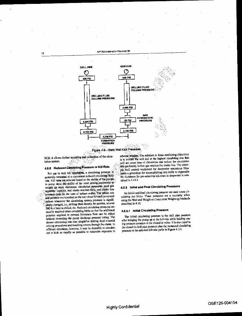
To understand how the various pressures interact. it is necessary 1.0 iJ;Qlate and idttttilyeachone, Fi~4,6 iUuslrlllel; YlU'i-0\18 pressures in a static well bore. 'Tbepri11 jtjil:~uge pressure plus th~ hydrostatic ptcs$U'Cofthc diiil.!tlg,tlili4:¢QUa.lSthc bottomhole~. The same P£l!ii:9i:!lt' ~ can be made for the annuIUl;, i.e., casing •. ~. plus the hydrostatic preSSUre of the lOIlllUln,s drlJiiU& tluldl'lus the hydrostatic pres. sun: of the influx cQ~,~ ~olc pressure.
4.8.3 Cil'Clli8tfi1gffe~lures The mau;"~~ losses that occur in a circwation sys-
tem.~ , :\l.. -"
i.fiii:rl~losses inside the drill pipe, casing, or work-:,(,ifcl $iriDg; t.: ~ drop ~ross the lIOZZl~ (lr water COlllSeS in the 'biihr shoe' .'.
3. Frict~ loss iI!'.1he aJllll.l1ar~ between !he weU bore and pipe; and, '., !i" ',- c.
4. Friction loss in ilii$lliface pipihj and connections. The total pre~1!!1h~~ otthe hole while circulat
ingls the SlII!l:Of#~ annular fluid column pressure {hy~~l;):piui;: \he annular friction pressure plus im~~~, The drill pipe circulating prcssfl.teis the'~ of all fiiction losses pIus corrections due to ~tyim~ between the drill pipe and trn" annulus plus ab¥:.Sed surface backpressure.
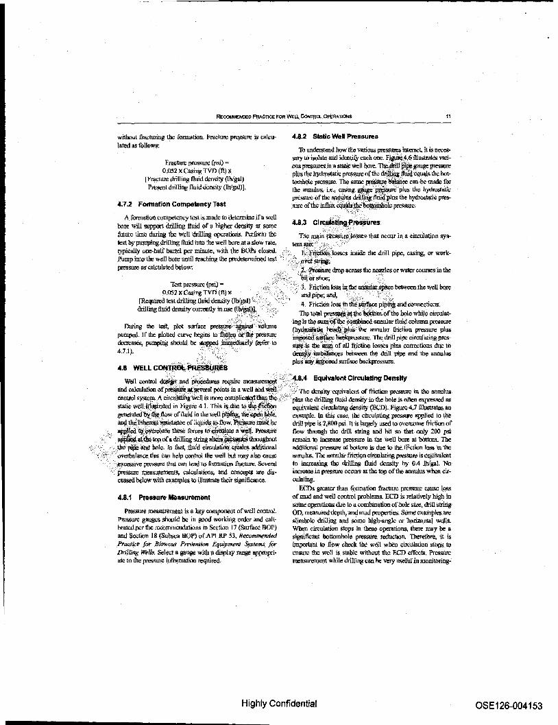
Well control ~Jlnd ~ require mea~~<):'·4 Equivalent Circulating o.nsity and calculation of ~ g~al points in a well and Wti/l"'i,; .·X· The denSity equivalent of friction pt'CSSIllC in the annulus rontrol systc~ A circulating"wcll is more complicatqi~ ,the," " . plus the drilling fluid density in the hole is often expressed as static wetl ill\l$trated in Figure 4.1. This i$due 'f!!~~~ equivalent circuIating density (ECD).Figute 4.7 l111.1stratesan geneMed't;y,,i¥ /low of Iluid in the wen p1~ thii~~, eJiample. In this case, the circulating pressure applied 10 the and ~~~ce of liquids 1A:I. now. ~!l;IiiiSI be drill p~ is 2,800 psi. It is laQ!ely used to QverccrnC; friction of '~cXl :tll~'il:iI'OOme ~ forces to~ a~. Pressure flow through the drill string and bit so that ooIy 200 psi ~~tQ¢ top of a drilling string alJciw~ihmughoirt remain 10 me- preSsure in the wen bore at OOtlom. The
.' the pipe:and hole. In fact, fluid eirculatiiIB. ~s additional additional prel!SuYe u! hoUmn is due to the. friCtion loss in th~ 'A-~ ,,' -~overtu~.lance that can help control die well but may also <:auSe annulus. Tfte annular friction ~latillg pre$S1.l1'e iSeqlrivalent
:~l<oessive prel!S1J1'C. that can lead to fonnation Ji,lcture. Seveml to increasing the driUing flujd dclL~i1y by 0.4 lb/gal. No pressure tneBsurememll. ca!ClUations, and coocqlts are dis- increase in pressure occurs at the top ofthe annulus when ClI'-cllSSl:d below with examples to illustrate their significance. cuIating.
4:'.1 PressuAJ Measurement
PJ:e!!SUI'i) meastlIemellt is a key COJll!lOneuf orwell control. .Pressure gauges should be in good worlciJlg order and cali· brated per the recommendations in Section 17 (Sllrfacc ROP) and Section 18 (Subsea HOP) of API RP 53, Recommended i'ra<;1ij;1? for B/(JWOIlt Pm'l?l1tivn Equip_TIl Syafems fOr Drilling Wells. Select a gauge with a display range appropriate to the pres!lUfe information required.
ECDs gn:aicr than fonnation fracture pressure cause loss of mud and well control problems. ECD is relatively high in some opemtions due to a combination ofoob: size, drill strillg on, me.asured depth, and mud properties. Some exarnp1esare slimbolc driIl.ing and some hlgh-anglc or 'hllrizonta] wells. When circulation stops in these OperaOOllS; there may be a sisnificant bouomhole pressure reduction. Therefore, it is impor1imlto now clreck the well when circulatioI) slOpS to ensure 1l1c wen is stable without the F,cn effects. Prcss!i1l: meslrurement while drUli1l8 can he very useful ill monitoring-
Highly Confidential OSE 126-004153
12 API REC()t.\MENOED PRACTICE 59
DRILL PIPE ANNULUS
DRILLING FLUID COLUMN PRESSURE
DRiLUNG FLUID , , ,> COLUMN PRESSURE: :', ,-"
GAS .--..I--L-_ HYDROSTATIC
PRESSURE
I 5;100 pSI I t FORMATION PRESSURE
",
F~ 4.1i-static Well KiGkP~s, ~ ,.-.;~. ~~, - .
EGD. It allows li.u1her mll\leling.na ca1i~on of the circu-lationsystem. ,:,'3~":~.~' ~'~" ',,~-' .:':~'?
adverSe~tbe solution 10 these conflicting objectives is to iniu\\le'fi\e well kill at the highest circolating rate that _ will nol cause loss of circulation and reduce !be circulalfun
4.8.5 Reduced c~ng~ssura or Kill-Rate ' .. _ preferably bofon: gas rca.chcs the choke line, The cXam-, .' _ ' ",' ,'p\ti:well control wo1'ksbee1 for del:pWater operalion.~ illus-
Fot use in w,ell kill '.~. a circulating pres~, is:" -'ms a procedn!e for accomplishing this (refer to Appendix b~Y nu:asI3\!1ld at a convenient reduced circ~ {\ill} rate, KiiI .,!irl; selected baSIXl OIl the abj~c9f ~pi).1jl~' B). Guidance for pre-selecting kill-rales in deepwater is con-
10 puIl1!l slow,tIiil,mlity of the nmd mi~*~,*' taimxi in 4134-
wciglltup _ iiwXimum cin:u1atiQi~#1u&gas 4.8.6 initial and Final Circulating Pressures ,", ~rCapal;ity, and choke reaction!~ and e'1ll:lke line , :;~~lui the case o[ su.bsea welislYtt.¢~ rare
, ,,~ pr¢!i5n'i'e are rcoonl!.:d on the tour shoct for dicll pump and .-: '0 WOOne whenever the drcnlatiog system pressure is signifi-
" ~y changed. i.e., drilling fluid density, bit nozzles, or over stl() n o[ hole is drilled, etc. Reduced circulating pressures are usually required when ciftulating lcicks so that the additional prcsstm: ICquircd to prevent formation flow can he added without exceeding the pump dischi!1l!e pressure rating. The sluw,er ciroulating rale 111110 simplifies drilling Ilu\d mak:ti1l1 mixing procedures lmd handling returns through the choke. In offshm"C situations, bqwcvcr, it may he desirable to circnla1c out a kick as rapidly as possible to minimize exposure to
An inilJ.al and [mill cin:ulating pressure lire used w ben circulating out kicks. These pressures are " necessity when using the Wait and Wcigbt or Concurrent Wcigbt;'1){l Mctbod~ descn'bOO in 4.10.
4.8.6.1 Initial Circulating pressure
The initial circulating pressure is the drill pipe pressure al1er bringing the pump up 10 !he kill-rale while holding casing pressure constant at the closed-in value. It is also eqllal to thccloscd-in drill pipe pressure pI.u.~ the mCIL~ circulating pressure al the selectodkitl-rate (refer to Figure 4.11).
Highly Confidential OSE 126-004154

RECOMMEHOEo PRACTICE FQR WELL CoNTROl OPEAAl1ONS 13
CIRCULATING PRESSURE
DRILL PIPE PRESSURE = 2800 PSIG
CASING PRESSURE = 0 PSIG
10.0 LB/GAL DRILLING FLUID
EqUIVALENT CIRCULATING DENSllY = 10 LBJGAL + ANNULAR FRICTION CIRCULATING PRESSURE = 10.4 LBIGAL
.052 x TVD
> Fi!wr~·.4, 7-Equivalent Cirrulating Density
Final Circulating Pressure
. ::. The final circul(l1ing pressure is the mellSUI"ed circulating pressure at the selected 1ti1l-TaIc corrected for drilling fluid deosityincrease.
}ilnal CirCulating Pressure (psi) = K.ill-ra1c PrCssurc (psi) X
New Drillillg Fluid Density (Ibigal) Old Drilling Fluid Density (Ibigal)
4.8 .. 6.3 Example: Figure 4.11 shows that, bellire the kick, tlle driller measured 750 psi at a. kill-ralc of 3() strokeS per minute, or 4.5 batrel~ penninute, u.~iog a 10.0 lbigal drilling
flUid. The sbUt-in drill pipe pressure of 520 psi indicates a required drilling aUld OO:lsity of 11.0 lbigal at 10,000 feel
Final Circlliating Prcs.'W"C (psij =
7'" . 11.01biga.l - 825 . JY psI X 10.0 U>!gal - - psI
4.8.7 Closed·in Drill Pipe and Annulus Pressure
Formation prellSIJre Dear lbe well bore is reduced during tlow. When a well is closed-in, the oorehole pressure rises Until ~ual to fonnation pressure. As the drill pipe and annulus arc in communicatiOn with the borehole, the drill pipe pres.mn: will al'lO rise aod stabilize. The ~bilized drill pipe
Highly Confidential OSE 126-004155

14 API RECoMMENDED f'RIIeTICE 59
11feSSttre indiL'llta; the amount 10 intrellSe !he drilling fluid density to balance the fOrmation pressure. If the w¢1l is not circulated, the gas influx will slowly migrate up the hole and increase the we1l bore and drill pipe prc8Sllres. Thcrcfure, drill pipe press1./reS lifk:r the initial slabiliztxl reading indicate excessive drilling fluid density increase. The initial slabiliud pressures are very Jmportllllt; they are the basis for detennining the fluid density reqWred 10 regain primary well controL To avoid excess "lell bore pressure due to the gas influx migrdling up 1he hole, lise a choke 1.0 bleW drilling lIuid funn the casing and maintain the initial shut-in drill pipe pressure. These condltiotls are illustrated in Figure 4.9.
4.8.7.1 Exll.111ple: Slabili¥etl Pressures of a Well ClOlitXl-In 00 a Kick-Fil!tJre 4.8, is a scheinalic diagram of Ii well sbutin on a kick. A W-barrcl gas intlux occurs while drilling at 10,000 ft with a 10.0 lb/gal drilling fluid. The stilbili7.ed closed-in pw.;sures are 500 psi on the drill pipe and 640 psi on the casing or alllllllus gauge.
DRILL
PIPE~_1
BOTTOM-HOLE PRESSURE = 5,000 PSI
fORMATION PRESSURE .. MOO PSI
Figure 4.1l-We\l Closed-In on a Kick
INCREASE DUE TO RISE OF GAS
DRIlL PIPE DESIRED VALUE .--J PRESSURE,
PSI
t TIME ..
F~~: 4.i:-CJOsed-1n DriU Pipe Pressure
~Jt:t.2~~: Closed-In Drill PIpe Pressure with a .' ~V\Uve, F4,<ure 4.9, 1.0 determine the clOlied-in
dtil,1 -pj¢::Pressure 'Yhen a backpn:~ valve is ill the drill ~ pressure should bcinc~ S)pwly using the smallest
." .•... pui'np available to opett&bac~yalve. That pressure i,iS the elosed-in drill Mle;~ ffl!asing pressure rises
whUepumping on 1Aii.'UriIl iiitl« pUm~ sholll., be slOpped and the increase .. ~.~nIi~1lI'C subtracted from dril1 pipe
4.8.1,3,;; ~~~ ~"Influx Migrating Up The HolH'igure 4,\11,iIlus\lll!tlS an e~lUIlple of It 10,000 II closed-in well .... -ith 1-(1',lllPlgaLdtilling fluid and a small volume of gas at bottom: ~-tbc gas rises to 5,000 ft without expansion or temperatUre clIsnge, the bottom·bole pressure rises to 7,800
"'psi. which is equiVUlenl to a 15.0 Ib/gal dri1.liDg Uuld Column. .' .'\\'OOn the gas reaches the mace, bottom-hole pressure is ·:,16,400 ps~ which is cquiVUlent to a 20.0 lhlgai drilling flum .. ' column. At 5,000 ft the borehole pressure is <lqUivalent to a
30.0 lbigal drillinglluld column to that depth. Such excessive pressure should be avoided wbether gas rises lhrougb a static drilling fluid column or circulated oqt by allowing the gas 1'0
expand as it riseR. Tbi.q situation requires that the pits be allowed to gain volume. If a gas bubble is permitted to rise in Ii well bore wilbout expanding, lhe gas pressure willl'tlVain constant. The reduced hydrostatic head above the gas column must he OVCl'C()mc by increased surface pressure au the CILy. ing; in tum, this increased pressure results in a higher bottombole presSUl'e-
4.9 WELL CLOSE·IN PROCEDURES
When Ii klck is detected, the well should be closed-in lIS
quickly lIS possib\pto minimize infi1J.X volume. 'I1lcro arc two close-in procedure options. the soft close-in and the hard close-in. The hard close-in minimizes kid: infulx volume is less compllcaled, can be performed by one person working on trn. rig floor, and is usually pcrfunncd faster than the soft close-in procedure.
Highly Confidential OSE 126-004156

15
INITIAL FINAl SURFACE Q 2,Il00 5,200 PReSSURE --+ PSI - PSI _ PSI
OFT
5,OOOFT
10,OQQFT
BOTTOM-HOLE PRESSURE
EQI.JI\IAlENT DRILLING
DRILLING FLUID
5,200 PSI
GAS 5.200 PSI
&7,100 psi
DRILUNG FWID
S,200 PSI
~ 10.400 PSI
FLWD DENSITY ,. 10.0 I..SIGAL = 15.0 LBIGAL = ZO.O LBIGAL
Flgura4·~1.~ Influx Migrating Up TheHo!e
4.9.1 Soft Close-in Procedll .. ,'.'. ";9.2 H~'~"in Procedure
Achoko is left tlpCAat all ti#i~ ~~1:han during a weu~~Wtis c1osod and the cboke$ re;main closed at aU control opcxation. ~~its;~()f~ monitoring of cas- times olhet'fuanduring a well control operation, The proceins pressure buil~~during cli:)siirC,' .;" important fea1:Unl.ifc:';.tlure is simple, allows well cl~ in the shorJest possible formation frM:~~~ng 10 the surface is likelj·Qr .. c;!ffno, and minimi1£S additional influx into tho well bore. rt is 1£ the initial closed-fu~1JresSure is Iikcly 10 CK£eOO·~··c· • titnlte<lto weIi couditioos where the maximum allowable castnaximwn Q~able cilsifig' Pressure. The soft clolle:'!h Pr~f.· 'ing ~ is ~ter than the anticipated initial dose-in dure ~;lilitiati()D. of pre-identified ~te,.~ pre_re II1ld a weIl fracture would not be expected 10 broacb suchastht'd.filllfhoke procedure (see ltl.~,IieIPnl~i- to the surface on initial closure. With the eJ(ception of the ml!!l~ al~ casillS pressure is JXlII¢bcd' nlCmaj&diSa.d- chpkt(s) i1Sclf'aud Oll,c cooke Iiuc valve located ll,Car the BOP .~. uil'lbe soil close-in pnx.~1l;i.1hat !~I!dditional ~ck, the choke line valves are aligo~ such thit II flow path
.. ~'~1~ in u~ the chQke liD.evat~~ ~io~ing the is open Ibrough the choke sysltlm. If the casing pressure can-" ;;_'thokellUoW/l additi<>nal intluxinto1heweHbO!i:. Thisresu1ts not be measured al the wellhead, the choke Bne valve is
- :..;;: jn a larger kick volume and potentially higher casing pre5Sllte -opcnud with the choke, or adjacent hig!J-preslIlJ.l'C valve ....•... wbile circulating out the kick thijs complicating well control. remaining clos.ed so that I,'>reSliUnl ClItI be measured at ~ -. lf the soft close-in procedure is contemplated, it sbautd be choke 1lllUli,[01d.
given consideration in the well p!'C-plalming phase where other steps may be identified to a1!e\-;a!e its need (higher SlTeIJh'lh casing, additinnal casing slrings, etc), iI can be well planned, and 1raining and drills can be coosidered.
Witb the ex~'eplion of ODe choke line valve localed nearlhe BOP, the chOke line valVe.s are afignel:1 such that a flow path is open through the choke sy~. The SI>ft close-ill procedure is:
t Open the choIce line valve. 2. Close the flOP: 3. Close the choke.
4.10 METHODS FOR CIRCULATING KICKS AT CONSTANT BOTIOM-HOLE PRESSURE
A.l1er a 1dck is stopped by wcll closure, circulation should be established, the kick 1;ireufated to the surface at constant bQttom-holeprcSSurc to avoid further influx. and drilling fluid density increased to establisb primary well conlrol (:refer to Section A-I in Appettdix A). When circulation can be establi8hed, Ihere are Jhree me/Jxxh; of' circulating Qut kicks:
I. Driller's Method-The weIJ is closcd-in; then the kick is circulated ollt without increa!ling the drilling fluid den-
Highly Confidential OSE126-004157

16 APi R~NOED PRACTICE 59
sity; after the kick is circulated oul, drilling fluid of required density circulated. 2. Wail and weight Method The well is closed-in; the drillil1g fluid density is increased 111 the pits as required; then the ldck is circulatqd out with the rcquIrqd density fluid 3. Ol11C\lrrent or "Circulate and Weight" Method-The well is closed-in; then circulation i.~ rostIIIlCd as soon a.~ pressures stabili7e; addition ofweigbt material to the oolling fluid is begun as soon as cir~'U1ation is star1ed.
4.10.1 Establishing Circulation
booed on ability to manipulate choke pre8SUAO to desired values and fracture prcssuro of tho last easing scat. Extra can: should be takl:n. with onl)' surfoce pipe set because shallow fonnat/ons muy breakdown easil)'. In general. it i. recommended t¥ \Vi:1I be killed first !hen IUise llIe drilliug fluid MOigbL ~l pmvi¥' tI:ic':4c;ired "verbal-!IIlCC.
4.10.1.2 Establishing cJrcllintillU"is: liot.idways possible, practical ur Iksinble,.1n ~ \;~~lti IU 4.11 fUT bullheading and top-kilt'kill 1~3iid to Scctian 13 for addressing lost circul'i¢i0.4~~ btoWOlll~.
4.10.1.3 E)Ull1lple;: S~~~ing of a Kick-Figure 4.11 illuslmles .-~~ ~ u1ki- cin:ul.aliun is initialed. The well was ;nitialIY e~-1J) with 520 psi 00 the drill pipe a,lCi
Therecommended proced!tte 10 establish a steady cireulat- 875 psi. OIi-th:l.aDimtus~ Circulation was initiatl;d and the .ing rate while keeping a constant bottom-bole pressure is a£ .c . -." ~)'eep 875 psi on the casing while the pump fol!ows;'W _ tIP.tlr,ihe kill-rate of 4,5 ban'els pet'minute {.l'O
1. Concurrently open the annulus cboke and slowly bting s~ pel: j]jiliQle}. When the kill-rale is reached, a pumping thepump up to the selecled kin-rale ,,-peed. ~Qf 1.270JISi on the dril11>¢ is indicated The pump-2. While bringing the pump up to speed, adjust the ehoke .. ' _ ~jlre!$ure js composed of the.lt,ick.pressure of 520 psi plus-10 hold the casing pre!o'SUteoonslalll at the closed-in va\.j!e':._ ~;~ necessary~OYeiWIt!P}I~frictian losses in the Holding thc casing pressure COnstal1t at !he c1~m .-;~,mous parts on1KH'irCiI~ .syS\elJl.~shown. Too friction value for the short time required to bring the pump 'Iit.!i}. 'lOss (750 psi) at 30 StroJc~·Pi:t~inute slIDllld have been mea-speed bokls the bottom-hole pre~ essentia1ly~; !IUl'ca and rccordcd~Y.~cc the drill pipe ~<:~urc is 3. With the pump running at the dcsircd~iiiJ(ilbc the same as th:smn:,oflbtflllosed-indrill pipe pressure am casing pressure s1ahilized at the desifeji vab1¢;readtbe the kill-nile ~ (~:W PSi + 750 psi), lID adju\llIDlIDl in drill pit)e pressure, The drill pipe ~ reaq-at this drill pipie ~ is' :lliiessary (rere.- to 9.6.4). The annular point is lhatpressure necessary toI1lll.inrama~sUmlliol- circ1ltli~pios!lt#c is assumed to be about 50 psi The bot-19m-hole pressure as 1011g as tI:!I1m~weigtil: and pump t01l)-~)?l'~is equal to the SI)lIl oftbe CllSing pressure .rate arc hcldcon.~tTiN .' cc lxi.twccn the closOO- plus ~:lt~c pressure of the annular Uuidl! plus the in and pumping drij):~' . ,. , .. ', 'Pressure req)lired anmilar cirCulating mction pressure. The bottom.hole pres-to cause the dril1ilit\uid 10 cin;.ulate al the de!rired rate. • ;:sijtc is aI.~ equal to the drill pipe prcStIW'C plus the hydrostatic 4. Detenlline the~9ftbedilsed-in drill pipe pressure. '1Ji'¢!ure of the fluid in the drill string less the friction pres-mil the I're-reCl.lrd¢.~~;circulating pressu:re, 1f the, ," :.~wss in the drill string:md bit. The bottom-bole pressure drill pipe ~)lre is aWr«iably different, investigat.e ~ ~~ equal to the closed-in drill pipe pre:lSUIe plus the
hydrostatic prossurc of the fluid in tllC drill string plus the annular circulating friction pressure loss.
ca\l8C.
Notc;~~ ii-p~uro due to choke n"'~~ ~ tWi:Si!Cconds per 1.000 ~l>fdrillSttillgtorogfs_~ the ~ipe sanae; however. th[Sla8inrespon~~eclln bll'1i\ilser \t.:Wge p kick i~ }ml'tIDl. " •••. •
.,>5. kccpthc drill (lipe pumping pressUft; constant by manipulating the annulus choke. while hok1ing a constant pump rate. If the dril1.ing lluid densily in the drill string is
• increased, redo.cCl the drill pipe pressure to maintaiJ) Ii COll-
slant bottom-boll; JlfCSSIlIC.
4.10.1.1 Annular mction pressure can be ,;ewed as a safi:ty ~t to pNVCnt formation fluid flow. This i~ bee_usc. in a circulating well, bottom-bole pressure exceeds tOt-mation pressure by 100 amount of the annular circulating pressure . . i\l1I\ular friCti011 pressure is usruUly in the range of 50 200 psi at 10,000 1\ which is the equivalent of a 0.1 - OA Ihlgal increase in the density of a stati¢ drilling fluid column.
Note: Additional CIISing pn;ssun: may be app~ to providl: more safely factor. This additio!llli snfety factor should be chosen caretilUy
4.10.2 Driller's Method
The ca.'!in!! preSIIUIC rcquircd to maintain a constant bottom.hole pressUre is dependentOll the type of funnatitln tluid IlJid a cbunging vertienlletq,>1h of lbl1llal.ion fluid in the H.1l1JIJ
Ius. Under actual conditions, neither the type 'lOT height or fonnation fluid is knoWD. Tbcroforc, drill pipe rressurc control shoUld always be used to keep constant bottom-bole pres!IUl'e when circulating kicks out of the annulus. In the drill pipe, drilling l4Iid d¢;i\y is ,known and the drill pipe pressure can be read 00 !he gauge. These factors, propcr1y nscd, determine bottom.bole pressure .... 'ith relative certainty.
4.10.2.1 The procedure descnlled for establishing circula· tion (refer IU 4.10.1 ) results in a desired drill pit)e preS!IUl'e at a constant kill-rate. To circulate a kick at constant boUombole pressurc without increasing drilling fluid density, circulating rate and drill pipe pret;SUre should be ~t Drill
Highly Confidential OSE 126-004158

DRILL PIPE
STABILIZED DRill PIPE PRESSURE DATA: ClOSEIPIN DRILL PIPE PRESSURE, PSI 520 KILL RATE CIRCULATING PRESSURE. PSI TOTAL (PSI)
Ill.OlB/GAl oRJt.LlNG FLUID
DRILL PIPE FRICTION
>750
1:270
PRESSURE lOSS. 700 PSl __ ~r
ANNOIAR CIRCULATING FRICTION PRESSURE LOSS ~ 50 PSi
GAS CUT DRILLING FLUID
FORMATION PRESSURE = 5.720 PSI .........
RECOR!lE!?-K!tl RilTE DATA STROKES. SPM 30 FLOW. 8PU 4.5 PRESSURE. PSI 750
~ StANO PIPE PRESSURe. PSI 1.270 ORiLLPIPEPRESSURE lOSS. PSI ·700 HYDROSTATIC PRESSURE. PSI > 5.200 BDTTOIA-HOLE PRESSURE, PSI s:m
,cASING -cASNG PRESSlJRl:, PSI 875 HYDROSTATIC PRESSURE. PSI • 4._ ANNULAR CIRCULATING FRICTION
PRESSURE Loss, PSi ...!..l!:!!. BOTTOM-HOLE PRESSURE, PSI 5,770
GAS CUT ORllLiNGFLUIO
17
10.000 FT TOTAL DEPTH BOTTOM~OLE PRESSURE· S.71Il PSI
PRILL PlPE PRESSURE bOSS PATA KILL RATE CIRCULAnNG PRESSURE. PSI 750
ANNULAR CIRCULATING FRICTION PRESSURE LOSS. PSI ....:l!!1.
DRILL PIPE PRESSURE LOSS, PSi 700 --, " .. ,.~-. ;
~re A-~i1~ilized Pumping Of A Kick
pipe~~b1dbe held con~1a.\lI.pyc~m;m;pu~n. Ci:n;utanQllean be siopped at any tmleand the~ke closed hi~prcssuro con.~tanl \\th~:~'t1Jc pump. CIO!ied·ln drill pipe pressure should be 1l:ie~ as when the well was original~ closed.
. 4..10.2.2 During circulation of the kick, gas expansioo and pit vuilQlle gain shQuid be allawed. As drilling Iluid voiu)De in the annulus decreases duG til gas C)(:pansion, higher casing pressures will result to maiorain constant bottom-bole pressure; but the correct bottom-hole presswe. win result at all :times from proper control of drill pipe pressure.
4.10.2.3 Aller the kick is circulated oul without increasing driJims fluid density, the lUlllulus should be full of drilling fluid. When the well is cfosed-in, the pn.'SSUI'C on the drill pipe and casing shoUld be the SIII,lle a" the original closed-in
drill pipe pressun;. However, the well is nol dead at this point, The wel1sbould be closed-in and the drilling fluid densiiy incroascd in the pits to the rcquin:d val.\IC,.
4.10_2.4 Circulation ofhcavicr fluid down the drill pipe at a CQIlStant rate will change the circulating drin pipe pressure and eliminate the closed-in drill pipe pressure. The drilling fluid densiIy In the annulus win not change while: Ihe he-dvier fluid is pumped tQ the bit, therefore a simplc way 10 control hottom-hole pressure i~ to use oons1ant casing pressnre. After the hea\oler drilling fluid passes the bit, the casing pressure will chaIlge; but drill pipe pressure need not change and <-'all
k used for control. The steps l!I'e as fonows;
1. Establish circulation at the selected klll-nde as dcscribod in 4.10. L Hold casing p1'CSS\ltC constant at the closed-in value by choke manipul~tlonwhile bringing the
Highly Confidential OSE126-004159
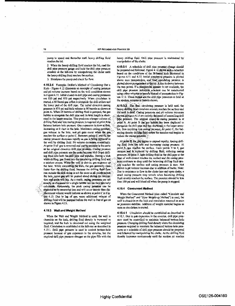
18 API RecoMMeNDED PRAcTICE 59
pump 10 lo-peeti and 1hereailer until heavy drilling lluid reaches the bit. 2. When the Ilea,,)' drilling fluid l\~aches the bit, read the drill P.ipe wessore gauge aud .bQld the drill pipe pressure conslant at the kill-rate by manipulating the choke until the heavy drilling fluid reaches the surface. 3. Shutdown the pump l'hdcheck for flow.
hl:avy drilling lltlid. Drill pipe pressure is maintained by manipulation of the choke.
4.10.3.1 A schcdu1c of drill pipe pro~~c should be prepared and followed. Figure 4.14 ~~ a sch«lule balled on lhe conditions of \he 50-bll.WL'kick iliusllaled in Figures 4.11 and 4.12. Initial c~~iwes-e is plotted above Z&rO pjU11pStrokcs, a.¢fiM(~Iaf.ing prcs.<rurc is
4.10.2.5 Ex.wnp\e: Driller's Method of Cirwiating Out II plotted above ~s t<i~0it.~1ine is drav.ll between the two points. If l!. ~~~ is not avail\lb\e, the
1Gck-Figul'e 4.12 iUUSlmes an example of casing press1.lle drill pipe pressure.t¢~'iiWi..J<Ciiedule can be ~1rucfed and pit volume im:rease based on the well condilions shown •• , in hgure4.ll. Imtial closcd--indrill pipe and casingprt=lres IlSingcithcr mit~'9r~lnstcad ofpumpstrolccs in Fig-are 520 psi and 875 psi respectively. When ciT~ulation is ure 4.14., Th~;~_the drill pipe pressure.~ tel hold at started, II 50-barrel gas int1ull is akIDgsidc the drill collars and the Slrokes,;minii~ «~ls shown.
the Iowc.r part of the drill pipe. The initial closcd-inca.~ing .... '0.3~<~·hlcireulating pressure is belduntil. tbe ~ is 875 psi 8IlIl kick volume is ~ barrels as shown at··tit;lvy dri~.llili.d cireulaleS around. reaches the1lll1'liIce and point A. Wben 25 borrels of drilling fluid is pumped, the gas tlie, ~I is &ail. Casing pressures and pit volume increases bubble is fIl~ !he drill pipe and its fotflllength is short-- sPowtt1dliigure 4.15 arc entirely !lIQ:losult of cootmlliIig drill ened in the la.tget annulus. This produces Illonger column ot c' ;~~. The original c_~~iii' easing presst1re is at dnlling fluid and les$ easing ptc~ is required at pOitlt R:~ , poinfA. At poiril B !llc~ J:a5 ~:li;IS been displaced \0
balance bottom-hole pressure, Gas expansion is slow at fnS!;' ", '&Iongside the drill pipe~iJ:~ ~jn the larger annuincreasing as it rises in the hole. Maximum ca~~c1iis. thtl.~ zcquirillg leSs, ~llTCssruli.".At point C, !be balgall vOOune in 1he hole, and pit gain occur ~_gaS;,' ancingcjensity~'~~theannulusandbeginsto reacbes the surface at point C. Between pOintS'tc'liild l\'llle . reduce the casing~/
casing pmssure lIect\:lIlii:S mpidty as gas is~~~ ~ in At .. ~' ':"'tbe "-'~. tel and ra""'" !Orcin drill-100 well by drilling lluidPit volume de~ ai:CIlidingly; jJOiltt~.;~~l'- exp ",-y, g At point J} all gas is removed and Cl!$lng~lli the same ing lWid Jiun(t/ie 1Io1e' and increasing easing pres$UIe. At as the original domo.in drill pip¢~~~<eaiimg p1'C-'iSUl'C point!';;'&3£ rejclies the surfitce, From points R 10 f, gas ---' '-"1 . ..... -' '"-- .. iA 0 l1..!A..J ;,..,u cscapC!r __ is;ctcplaccd by drilling fluid, rcdncing casing <UlU \lUi PIj1C pressure aJ'C-....".sarti¢,''''''lIU!Ii: .. v. .ry~"",o. """''''"''. '''''';;;':;; ... F, I; ..... t drilling' tL., .. tn' the ·drill mpe ....... ing tluidfills both the:drli.l~ afia~. DuriIig a kick .... -- l'U"...... ueu uuu r '" .....
whiI drill' ,,-~:,' the .. l' dril"~ft ilr'" ...... - of well elnsure reaches the surface and !he ClISiDg pres-t· mg. gas = ... ~JlllO ,.~ atmg ""'to . ....,..,.. ·~rontinues to drop until the bata1lcing drilling. fluid den-
a Il1i>:~ occurs. Wliliii~'Y~ri.ii shut-in. gasmignlles up;'~, ·,1v:~!c'~bcs .. the surface.. . aud castn' g p"'f""~ ;~ zero. Not. the hole. While eircul~1bi;itnCk, the gas generally rises ,- - .".~~ ., faster than ~driIling fluid 1k:ca\lSe the drilling quid trow: .·.~$htiwn is pit volume increase due to addition of barite. Note: rate OUlliidc t1i.c:kjn string is not the SIIIIl(l at aU po~~:.. Due 10 resislance 10 !low in the choke line: !lIld open clruke} a the ho\e~wne_~ll be; pushed ahead ~JI:lI:'~' IIlilaU casing pressUTtl may remain when balancing drilling
_ lion 8!l!f~ ~. hig. N. a result, c~ preSlI\lre$ ljlC'rot fluid qcnsity reaches the surface. The ptossUrc lloould be less .'~'>!e.~'.~ ~ fur a 5ing1.e bubble ni)i.~ 1hef~is\)ly than 100 psi and will bleed otl'wben 1he pump is stopped.
" calcUtiibt.e,J<b.rulIlately, 1he peak cm.-mg ~'can be <." ~t¢d"k> '6e somewhat less and '1\lill occur sooner than dis
., ..J4accmcm vn\umc would indica.\C as shawn at point C ill. Fig'~4.1~. Due to lag of ga.~, some additional vnlumc of
drilling tllrid will be pumped before 1he well is /iee{)f gas as jloown in Figure 4.1l.
4.10.3 Wailand W.ighl MethQd
When the W~t and Weight Method is used,. the well is closed-in on \he lcicl<., drilling lluW den&\)' is increased as required. and lbe kick is circulaled out using 1he weightecl fluid. Clrculation is eslablishl:d at the kiU-raie as cleseribt:d in 4.10.1. Drill pipe pressure is used 10 control bolloin-lIo.1e prcsstrn; because of gas cxpansion in the annulus, but the required drill pipe pressure changes as the pipe tiUs with the
4.10,4 Concurrent Method
'When the OlllCUll'ellt Method (also called "Circulate and Weight Mel1wd" and "SloW Weight-up MelhOO") is used, the wen it closed-in on the kick and circulation ItlSl.rrnoo as soon as pressures stabilize. Addition of weight llllIteria1 begins as soon as circulation is started.
4.10.4.1 Citcuhtfion should be eslilblished as described in 4.10.1. ()ue to gas expansion in the annulus, drill pipe pressure l.1l\ISt be controlled to tnaintain balanced lxIttom-ho1c pressure. Chllnging drilling fluid density alters 1he cir~ulating pressure required to maintain the balanced bottom-hole pressures so a schedult: of drill pipt: pn:8Sure should be ~ and followed by manipulating the choke. As the drilling fluid density increase§ continlltJUsly until the suction pit reaches
Highly Confidential OSE 126-004160

:J: cO· :T
-< () o ::=I
~ (I) ::=I e !!!.
o en m .... ~
~ -" 0> ....
~ c iii. ~
g ~. ""D
j iii
~ ~ ~ c i ;;0
! 1 l c !!!. tS :) CD
~ ~ i 8.
f K!
1400
1200
1800
i 800
f
~ CI 800
~ ; 400
200
.& BlJ88LE IN DRILL COLLAR ANNULUS GAS BUBBLE IN DRILL PIPE ANNULUS
weLL DATA; 10,000 FT TOTAL DEPTH 50 BSL& OF GAS FEEO.fN 10L~ALMUDC~LAlED
500 Fl Of 7" 00 DRlL~ COLLARS 5" 00. 19.11 LBIFT Xli DRILL PIPE 9 71." DIAMETER HOLE CLoseD-IN DRILL PIPE PRESSURE - S20 PSI INITIAL CASING PRESSURE. 875 PSI -
CASING PRESSURE. 52Q PSI ,;/\
-::_------r- \ INm '-- \ AL .GAS VOLUME VOLUME AND P = 50 BSLS IT GAIN \
~ ~
I ~
! i
I ~ -150 ~ j ~ I ~.
-100 ~ I III
I 'rD -so
I 0' • 10 o ~ ~ _ 400 ~ ~ ~ 800 ~
BARRElS PUMPED
I I ~ ~ ~ ~ i i
;;

, \
API RECOMMENDED PRACTICE 59
RESULTINQ CAlliNG PIUOlISURE, PSI
I I
_,--,-L,----1 ~ 8 i 8
'188 'NMllId tIO ;J"iOH NI SV!)
Figure 4.13-Casin9 Pressure and Gas Volume Using the onDer's Method
Highly Confidential
\ \
OSE126-004162

:J: cO· :::r -< (') 0 ~ ~
~ ~ c:t. !!!.
o en m ......
~ ...... 0) Co.)
"Tl (15. c: a f'"
t ~ = w - Ix:
i ~ ~ &! III ~ C 0.. a a:: &' ::1 =r rz .~ 0
(I)
~ 9' (I)
.~ "'" III ;;; c.
~ cO· a: ~ l
16.00
1200
KILL RATE CIRCULATING PRESSURE 750 PLUS CLOSED.IN DRILL PIPE PRESSURE "'520
II = INITIAL CIRCULATING PRESSURE 1270
1400
1000
800
600
400 KILL RATE = 4.5 BPM OR
30 STK f MINUTE
FINAL CIRCULATING PRESSURE
= KILL RATE NEW DRILLING FLUlq DENSITY CIRCULATfNGPRESSURE x OLD DRILLING FLUID DENSITY
= ·750 PSI x 11.0 LB/GAL A,.. K I "",,.. .. '.
=825 PSI 200
DRILL STRING CAPACITY = 173 BBlS
d. d. a 5 10 15 20 25 30
PUMPING TIME, MINUTES
35 40 45 50 55 60 65 70
o 150 300 450 600 750 900 1050 1200 1350 1500 1650 1800 STROKES AT 30 STKfMINUTE
1270 1220 1160 1100 1050 1000 930 870 825 DRILL PIPE PRESSUR!!, PSI
, f g ~ F
~ ~
f
~

ill ~ l
I ~
~
~
I I * ~ ~
f200
1000
lIIIO
600
400
GAS BUBBlE IN DRILL COLLAR ANNULUS
/ .GA5 BUBBLE IN DRILL PIPE ANNULUS If JBALANCE.-~rU'"M"m~ //~ ~ .. ;/
B"..,o-~~ t --o--_-c&.~ .. --
10,000 FT TOTAL DePTH 50 BBlS OF GAS FEEO-IN 10 LB/GAL ORIGINAL DRIlliNG flUiD DENSITY 11 LB(GAl BALANCE DRIlliNG FLUID OENSITY 7" 00 DRILL COlLARIl .500' 6"QD,.19,5LBlFT)(H DRILL PIPE CLOSED-IN CRILL PIPE PRESSURE' 520 PSI INITIAL CASING PRESSURE' 877 PSI 9'18· DIAMETfOR HOLE
200 I, ~ GAS VOLUME
i INITIAL GAS VOLUME. 50 BBLS LIGHT MUD TO SURFACE
.,250 1 1 1 1
J200 lh 1 ~~ lr 1150 ~ 1 go 1 m~ I. o~ ~1ooh 1
",,, ~~
1 en 1 1
150
I I I I
700 800 IlOO 1)1 " ~.J ~I
300 400 500 600 100 200
BARRELS PUt.!!'ED -)
- .~ LEGEND: ALTERATION DUE TO MIXING DR DRILLING FLUID AND GAS ( -
~ ~ J:: .2'
~ --g
111
I g> 'iIi :::J
~ aI <:: .. ~ ~ ! m 1!! Q.
aI
.~ (.)
I ~ J, -..¢
!!!
~
~ ..-~ o
I (0 N ..-LU en o
a; ~ c Q) "0 I;::::: c 0 (J
.2:-s:: 0)
I

RECOMMENDED PRAc11CE FOR WELL CONTROI.OFE,RATIONS 23
requ:i1td density, priroe requirements are oontinuOUSIDQBi.1or- reaches the bit and sluws Ibecasil1g pre_ ~ as itl10ws ing of the fluid in the SIlCtiOll pit and recording the time each into the annulus. At pgint n, gas volume begins 10 increase, {Y.1 lhlgal. increase in drillins fluid dcllSity OCCU!'S. These ovClJ'iding the increasing annnlar dril\ini fluid dcns.ity, and Time~ are use(! wiTh circulating tlrru;$ to The bit to mllke the requiring increased ~ ~,,~:pojnl E. ~ bas drill pipe pressureschedul",. Weighting is dotlC;l ~ it revtllOe reached 1he surfllCe and casing ~~jS aiJ~IIJlLXilnum. AI; circulation is established between the suction pit andan adja- gas is freed and replaced in the hruel'iy'4!illiniffluld, the cas-cent pit through allXilialy punips so fluid @~ity in the sue- ing pressure c:\rops until poW;J!l$'~chttiiind light fluid that lioll pit inC1'i:llSe5 at II sloW, even rate. The rate the Jlnid was in the arin pipe at t~. -wne (jf:Close-in reaches the sur-(lensily increases depend:; on the rate at which weight mate- [ace. Casing ~. ~o~ ~~n:ase li)ltii balancing rilll can be adde<i and the circulating ra1l=. In some instances, drilling fluid density~QlJef'lhi:.$uTface atpoint G Note; flue the addition rate may be insufficient to bring tile circulating to n:sistancc 10 tlo,w iIi·illC ~kc manifold and open choke, a dtiIling fluid to desired density dming the fimt circulation of small Casing ~l\laylflrmin wben the balancing drilling weighted dril1in~ fluid, If $0, the fluid golng in the hole wl1l fluid de1lsitY~~ ll:re surface. The press~ $bould be \e8s stay at the 8~ stabilized dem.~ly until wt)ighttxl fluid thunlOO'PsiaDdwiltb1et:doITwhenthepumpis!>'toppe<l reaches the Slufacc, then the density in the suction pit win ~" ',",:, agam increase, Thi~ circUfilldance Is automatically handled, \';~'~,1FijbN.cIRCULATION KILL METHODS as the prepared drill pipe pressure schedJJle is based on the ' "'" , ,';, , ' llel1Sity bf drilling J1uid b!:ing pumpel,t, ,,' 4.t1,1 BuHhellctlng Operapcms
4.10.4.2 ExllIllp!e of Drill Pipt: PreSIlUre Schedule {~ " BU11hcading is continuouJ 9~ of irufilcicntly OOIl.'1C GU~t Method) Hgun: 4.16 iIlustnlleS a typitlll drill. . ".aUld to klU the weiL,~~pPet'ations are usually prcssuro s{)hcduk ptclW!ld for the SO-band kick abiJ~"" ' ~ emplpyeQ when an~ StJtfit.ie pressures exceed the U()1lS illustrated in Figure 4.12, Dri1lingtlUIIJ, ~ maximumthatcansafeIY~fia!ldle.~:\J'whentheinJlux"cotl-increases ofO.l or 0:2 lb!gal are plotted alAAiJlie.~ttoDt Of 'Iains hydrog¢n..~ ~r ~c, iJlmoot safety be handled lhe graph from inil1allO fina\ drilling Ouiq~s; l,:!re ini- at the Sluface,~iJh~ is often (!Sed in well serviCe oper-rial circulating preSSUTC is plotted abo~jhciil1tW drilling atiooso,~.,~ljngis difficult due to a depleted forma-fluid delL~ity and the final circuJ;lt\!l8"~ IS plotted tiQlf,'(;~Jn driJilnlibpetations, bullheading reqllires stufuce above the final drilllng fluid ~'.i\,JiDe'drawn between ~s ~;Will exceed fOl1lla1ion fraclw'c prcs!lUro, In the two points indicates the d~tplpe:~ures 10 boW when 1Ii*~well bore fluids are often pumped into the the dril1 string is one-li'l'lf}wtbt;~e, ~ng drilling ~~ exposed in the open hole, which may not be the fluid dc,n.~itics sbdVn; 'these ~fic read from the graph "7', . formation that orlginally lic\red, For these reasons, blllIh<:ad-recorded. The time'~ld.pressnre read is obtainedl71 ,il11! is more slIccessful if a long string ofprotcctivc pipe has adding one-half C~~'lO the bU-lO the time at wbMl ,~n8et ani! the open-bole section is relatively short. Bull-the SUction pit read~ i~ental drilling fluid. den~ Jieading operations can be \\Sed with pipe in or ont of1be hole OOte the baia'ncing drilling t1nid dcn.'iity !Cache,,, tlii:~i4c . ' and 10 force: lost drculalion malenal ink> a fonnatiOIl
corre~.final drill pipe pressure ~ ~'lliM\i!ttll 100 ~~Jluid density reache~the~: D~lht, pei\od~ dnlilng fluid density il i~g Ul.~SUc1ion pit,.Jhc dl$ pipe bas higher drilling'fliIi(t pc . at the top
thtiit'ii.l'~·'boltom. tr1be time to bold 1\ "", an iIlcreineJii'ofdrlllingfluiddensity is based"n killit Circtilating time to the bit, a sm1Ill lII1lOUIIt of excess bottom-hole pressure n:sttlts from the shallower highl.'f density fluid The cxcess ptellSUre IS appm!(hnately eliminated by hosing the drill pire pres~ 'SChedule on one,balfthe circulating time to the bit.
4.10.4.3 Example: CaSing PressunI (Concurrent Method)-F1b'1Jte 4, 17llhows typical casing pressu1'tl!; resullr jug from use of the Concurrent Method. The original closedin casing fllICSSlli'C at point A reduces to point B ducto the ga.~ bubble soortening and more drilling fluid eollllIln in the annulus, At point C. drilling tluid of slightly increased density
4.11.2 Top Kill (Lubricator Technique Operations)
Top Idll 9perations provide a method of redllcing surface pressures iII a w.ell when gas is al,the surf~ anilcin:ulatlo!l cannot be established or1he pipe is out of the hole. The procedune is a.~ follows:
1, Mix kill fluid of sufficient density 10 elllitlre lhata minimlUtl volume of kill fluid will be necessary to redllcethe pressures to kill1bc well. 2, Pump II measured volume of kill fluid in10 Ihe hole until the injection pressuTe reaches the predetermined maximUlIllimit 3. AlloW drilling flni<\ to settle, then bleed gas (Note: Bleed dry gas only, do not hlced drilling fluid,) until the pressure is reduced an amount equivalent to the llydro· static pressure of the injected kill fluid.
Highly Confidential OSE 126-004165

m \.'!
l ~
I ~
it
1000
10400
1200:
1000
~
600
0400
200
10.0
1270
050Il
19
0519
Kill RATE: 4.5 BPM {30 STKlMINUTE) DR,lll STRING CAPAC\T¥: 173 BBL$.
CIRCUlATING 173 BBlS • 38 MINUTES TIME TO alT' ~
10.5 10.6
lKU-l RATE CIRCUlATING PRESSURE 750 PSI 1
' PLVS CLOSED-IN !)RILL PIPE PRE.SSURE + 520 PSI . • INITIAL cIRCULATING PRESSURE T,2'7o"I!Si'"
10.7
FIN.6,\.. IiIRCUlATING PRESSURE
~KIU.RATE CIRCULATING PRESSURE. NEW ORILLING PlUID DENSITY
<:ItO DRIUlNG FL\JID DENSITY
11.0lBtGAl = 750 PSI ~ 10.0 LBIGAl
= 825 PSI
10.8 10.9 11.0
10.1 1(1.2 10.3 10.4 SUCTION PIT DRIlliNG Fl\lID DENSITY. LI!lGAL
1225 1170 1130 1100 1050 1010 ~ 920 870 825
ORIUlNG PIPE PRESSURE, PSI
0515 0500 0550 0615 0637 0700 0725 0755 0825 0855
SUCTION PIT TIMES
19 19 19 W 19 19 19 19 19 19
ADIl ONE-HAlF C\RCULATION TIME TO BIT
0534 05>19 0609 0634 0656 0119 0144 0814 0844 0\114
ORILl PIPE; PRESSURE TIME
i ::t
~ is c 0 t( ., :! i S !
I 0..
! 0:: F-a ~ ..r !! ~ .91 LL
~ ....... ~
~ LLi en o
(ij ~ c: CI) "0
'E 0 ()
2:-a I

------------------........
RECOMMENDED F'IIACT1¢E FOR WEu CONTROl.. OPSV.TlONl! 25
1400
1200
BU5l!LE IN ORILL PiPe ANNULUS
INCREASING DRJLLING FLUID DENSITY AT SIT
GAS BCGIN5 RAPID EXPANSION
WIIi: WELL DATA CONDITIONS SAME AS FIGURE 4.1~
~ ALTERATI(lII DUE TO MIXED ORILLING flUID AND GAS (-- -- --
BAlANCE DRILLING flUID TO SURFACE
250
Q~ __________ A_ ____ ~ ____ ~ __________ ~ __________ ~~a_ ______ ~
o 400 1200 2QOO
BARRElS PUMI'IlD
The f~~ng is a IlltthOO for calcu!\ItiIlt! I~:~; , ~~tion. .. c .. '.
. '.. '~'Hydf6static pressure ~ (psi);"-"J,f)i kill fluid densi!y(lblgal) x vOl;-i!j~f~h"bls)
.' 2 ' .... ~
(cas,ing 1O,m.) (driUpi.pe 00, ;~ .• )~
"Note: If pipe is out the hole. UIle 0,
Example; For 8 bbl of12 Iblgal drilling fluid pumped in10 9 S/g_in. 36-lbifica:.'ing with 4 112_in. drill pipe.
Hydrostatic prcs.wc rcdIiefion (psi) =
53.5 x 12 x 8 53.5 x 12 x 8 = 81 psi
(8.921/-t4.5)2 59.334
4. Rt:peallbis procedure unill1be prtJssun: is reduced 10 7CTO or thc hole is full of drilling fluid 11lc injected volUIlle incJe1llents will reduce with time. Th.ts may he a very
lengthy.procedure oonsuming hourS or days. If the pressure cannot be roduccd to zero, a snubbing operation 1I18.y beroquircd.
4.12 COMPARISON OF KILL METHODS
Each pfthe methods. bas relative arlvantages1l.n4 diSadvantages. The Driller's Method is the simplest to handle and to teach; but it requires two cireulatlon.~ and may rcsnlt in the highest casing p!"C.'ISUrC a.~ shown in Figure 4.18. This also means 1bat a bigher casins seat pressure and lOst circulation ate more likely. 'The Wait and Weight Method ~y pr0-duces t.be lowes! casing pressure (ol1en les/l llilUlinitial closed-in p~) due 10 ass1slance of in(.~ drilling fluid densl1y in the annulus wllile the gas bubble is ein;utated to the smface_ Ilowevcr, tJlis is true only if the drill pipe volume is lew !ban the !IJlIlUlu~ "olume and kill weight mud enterS the a:rmu1us before thc gas b\lbblc rcaellts \Ix; su:rfaec. Ouc tQ the effect of pressure at the casing scat and asSOciated danger of lost circulation, oonsideratiou should he given to
Highly Confidential .......... ------------ OSE126-004167

26 API RecOr.\MENDED PRACTICE 59
use ofllie Wait and Weight Method, especially if unly sunace aIliing is set. The wait and Weight Met110d is more complicated than the Driller's Method and stuck pIpe may occur wbile the drilling fluid pits arc wciehtcd and the kick not circulate~l. Other cunsideratio!ls uf Il1e Driller's versus Wait and ~ Metho(ls aretirneontbeBOPs, availability of weighting malerial, ability 10 mix mud and cin:ulllle. bydrales, gas miption rale ([unction of hole angle, inQux type, drilling fluid type), and hole type (straight or directional). The ConCIlJ.lCnl Method has thclcast danger of stuck pipe, as there i~ less tilUc with pressure on the well and les8 t.inx: with an tmcirculated kick. For the Concurrent Method. casing presstires are intermediate to other methods; however, it is the lDOlil cumplicllled 10 run. BuUbeading and the Top-Kill Me!hods lire for special siluatiuns where circulation is iinprnctical or high surface pressUre needs to be handled as descn'bed in 4.11.1 and 4.11.2.
4_13 CHOKE LINE PRESSURE--SUBSEA STAC~
When handling kicks in deepwater, flow .resistance,iil~~ ~ choke line from the BQI' !rtack to the surfaccpl.ns the ~~ fold and oJlCl). choke may be significant. Unless W1~~ .ii1\!;. low and the choke line pressure properly ~lniO·~ . during well kill openUlons. excess pressures ~f~~ sarily applied ill !he hole. 'Figure 4.19 h1W'~ ~'ptessure losses for pipe of varlons insi.® '. . .. ~ried flow ra1X:s. However, restrictions in join$;. ; ~. and choke C8Il add additional pressun:s..~ii!; ~~ nia:F actual rncasuro-ments on the rig. . ... >... . .'... ..
. ;-'": .. " 4.13.1 Measurementot SUbSea Choke l..ine
Pressures c'. ,,<. . "
1, Befme drilling oui surJace C'd!Iing, de1imIrine Ibe drill pipe circulating pl'l:SSlll'C through !he dnl1 string, choke line, and open choke using 11 c1.ostd BQP ~ at least three. circulating rates. Plot on log-log paPi~~ draw a line through lh¢;c poims. ,». .' ';
2. Determine kill-rate clrcullltjng '~fur at least Ibree drculating rates wi1)l.f3OPlr'.op6n; PIoI un a graph and drawa line through ~~, 3. At three or ~.f!iIw ~~~ct values obtained in Step 2 from tbose ~ ill SteP'land plot values allbe same flow ra1!lS:: 'OraWa ,lill'! through lhese poin1s. This shows chokycalidClmb l1nC PreSSUICS for ~tcr depth and drilling tlui4:~.c()rrected choke line pressures are o~ t~ !!:~~ling lluid density by using lhe ful-
, lo~. ~la at two or more poin'ls and drawing a ':~~1.ip¢,.
";';." .. Corrected Choke Line PtiJssurc (PSi) =
. Choke Line I'ressure.,Petei:i:iuned (psi) X
. I'resent 0ri!\!ilgH-'#~ Obiga!) .. ';J)iilling Fluid DoiIDty who.It~l:~lIiI;&suro DQtCl1i1in.OO. ; '. .(I)r-aail'
Using two tlO',1(~:'~"~~ and kill lines, reduces the choke ®",i\!lelnes~,by afuclorofappfi>lcimate\y four (4). Th~,lftbe~is~ofusing both IineslOt\1echoke, the ~ ~bc!q)Catcd u~ing both lioos in I\lCflI and ~. a~:aoo c~ line pressure. At low flow rates. Iaminai'ftQwii'riiY result catlSirlg some plotted rosulls io &t-
,ten. The pmcedure pTO\~des dam for the water depth at the '''fj;uic; of ~mrolllent If pressures on the manifold gauge .~ ...... alS!) kad. ploned, and sUbtracted. the pressure tar 100 feet of
'.'0: 'cld.e line can be calculated and a graph prepsred The mani-
The choke,Iili!l'jm:ssure at any one rate is ~ driUfuPe:,~:fuld open choke readings iShouid be ~ded back [or each culating ~~ ~ith BOPs closed l1lld the 'Cl!Q~ ~~: depth. Figure 4.20 illustrates the results Of thCsc JTICa$lTC-
choke Ildt, ~.JnlnU8 the iliiU ~:Fircutaling ~ ments and oalcula\ion.~for II particular rig. EachIig will have a .. with' W:)Ps~. Urtless the choice lmttiTe~sun: {, ~'$s than tmique graph depending un the inside diameter of the choke the ~-i~',~ pressure, II balaru;edbollnlll-hqre pres- line and the arrdllgemenl of Ibe clru.k.!: and nrdllifolli ~ c8Uiri'bccstabli~bcd when circnlatiOl;k~ Drill
, ,~,t»Pc pressure will be higher than desired and ibc choke will , . '. :be·wide open. Also, even if the initial driU pipe circuhlting ~ ~ be established at correct value, there will be some period in the well ki\ling operation wbere the choke is wide upen but the drill pipe circu1ating pressure is greater than desired by the amount uflbe choke line pressure. therefore,. a grapl1 should be prepared showing choko line prcssulu
.at various fiQW rateS so that II kill-rare can be selected that has a choke line p!e!lSJl{e less than anticipated closed-inca.<ring pressure and so that the excess pressure in the well dIle to choke !low line rcsi$1nce ~ be evaluated The procedure.is 115 fullows:
4.13.2 Direct M88$Urement of Choke Line Pressure Lo.sses
Oloke line pressure loSSl:S coo be 11lt:lI8Uted din:clly by plunping into the choke Ilianifold, tlown the choke lioo or choke III).d kin lines into the o{lCll BOP stack, and up the riser. The pressure .shown QIl. the choke nUUlifold gau~ is the choke line' pressure loss. Arrj ert'OIS CllUSed by 1!IlIIIl1 circulatory pressure losses in Lhe ris<:r ~ negligible. <:-'hoke line preSStJre ~ aI !K:Vcral rates can be plotted 011 log-log paper andcxtrapolatcd to provide estimated pressure losses at varions pump rates. Choke line pressure loss measurements should be repeated whenever dnThng lluid properties are signifiemnly changed,
Highly Confidential OSE 126-004168

:::r: to' ::T
-< () 0 ::l ~ Q. (J)
a 
API RECOM,MENDED PRACTICE 59
28
PRESSURE L05S.i>SII100 FT
'" o 0 ~ ~ ! O.-______ T_----~T-----~r-----~r-----~~------
;$
Vi
'" ~ ~
'" E ~ ."
8 ~ '"' c ... '" ~ ~ m :z
u; '"
-i
... ~
"" 0 .~ ~
'" s:8 !< i l"
};I
~ ~ ! '" IV
'" IS ~ Q ~ c: ffi ....
.... g bl
'" tt '"
'" ID
~ '"
8
<i
Figure 4.19--PI'essure Loss versus Flow Rate
OSE126-004170
Highly Confidential

------------------........
29
'I 'fL IIi Ii V VL IL 250
J '/ II VI L IJ '1/ J I V
t //)11 , "/ / I
/1 !JV)IJ If VJ if
J l 11111 1 I .;;1, III ~ , I
f N'1d L J If J~ Jj "'f~ I J
'1f1L L ., I(
1/11 J' / J '1~1
ISO
I ~ 1110
..J 80
I : ... 10
50
J II II ., VI V 'I j
'J J V I I I 30
/ I I I I I J I '/ I / I( II J' BASED ON IIEASUREMENTS
J WlTK9.oL!llGALDRlLUHG FLUID
IfJ 'I / '/ ANti U25IN. INSIDE! DIAMETER
V ~ LINES.
j
I. 10
40 SO 60 70 80 80 100 150 200 250,lOCI 4CIO 500
ClRCULATKlIII RATE,GPM
I I I I I I I I I I I 2 3 <4 5 8 7 • 9 10 11 12
CIRCULATION RATE, SPM
Figure 4.2O-Pressure Loss through Choke Une and Manifold Wrth Choke Full Open
Highly Confidential OSE126-004171 ......... -------------

30 API RECOMMENDED PRACTICE 59
0&.13.3 Handling Subsea Choke Line PressUIU During Klckli
The kill line can be used to monitor casing pressure when circulation is begun after a kick. The kill line soould be opened to the surlace manifold and the kill line pressure held constant by adjustmenf ofthc choke line clloke wbile~ing the pump up to speed. The kill line should also be opeIIf(\ to monitor ptl:S.W1l during any cbanges in circulation rate'. If it is .not {KlsSihle to utiliu the kill line pl'essure. the choke pressure shoul({ be lillowcdto drop an amount equal 10 the
calculated <:ir m~~ choke linc pressure lo~ while bringing lbe punip(s) up 10 speed. OUwrwise, the drill pipe »feS~ will be too Irigb as will bottom-hole pressure and pressure (It 1he casing~. Even When conect drill pipe pressure iseslablished there will be II time near the end of the kick kill operation when the choke will be wide open and the drill pipe prossuro will build to a value higher than desired by tho amount of tlle choke line pressure loss. The recommended. . well control worlcsheetsfOr subsea stacks present pr~: slep!l fur handling choke line PreJ;S1rn: during kicks (.lu Appendi" n). . ..
<,". -,
£Jq'lerience bas sbo>/l.nibat low ~~lIdown pressures arc cxpcclcd in deepwater. FOi,cli!ivlin dcptll the _" .. a-1C<head plus the soil ~td\:n ~re is;!ess than the total
4. 13.4.1 The truutimum initial circulating ra1e \hat will ool
cause furmation breakdown can then be delelmined as fol!Qws:
R = Circulll1#t~~te; sP'll , L = choke 1in&~)l,Mft '
Pk = C~1J$~ldplussuTC. psi
Go. ": drilting ~ gradient, psilft
D{ t .~ ~tcr ofchokc line. in.
~ is ~ l'lIIUimum rate at which the kick can be circtIlated~~ the rmller's Methodor, in the case of the Wait _~ Wdili MctOOd, thcmaximUlii'initial circulation of a Iitulti-,rate kill. The calcull1iinil~pressu:re losses.
-, ' . _-" - ,~:"- .', ( . -:- , c· ,
'''.13.4.2 The gradient-oroa:kill tluid:1hat will batance the . i:naxinmtn kick that catlbe GNawitbi>Ut clUlSillg fortmltiOn
I1"acture ClIO be caJ:c~~ ro!illiVs;
(Equation 4.3)
soil overl>!trden p~t1he sanie~ rOT a land or shallow wo,uer locatiOn <_ densiWls WSII \ban rock density) ..... Due to tile higb frictiofi.lo6iI! in ~telatively long choke~' ,. used With SUbsea. stilcb iIf~ it may be ~1lt •.. ~ .. ' cll'cuiate out 11 kick at a very sloW rate (le!lS thao ODe-.h!ilf ~< •
mal tiIcullltiiit~) to avoid fonnlitiou ~1'hl'tiIi::t' . should bo ~ in selecting 1cnt,ra1CS;ii,rC~ ~~~ btifu dr~"Ulale any ~J~C®be'~-in
;;.- a .1.bid:Win DO! c~ wrtllalion ~~ ~a!;bing ;. 9f.£~~beensetan4fonnationb~~is
:> ~ the maximum choke mamf~ pressure that can ':" ~ . shJlt-in wi1:bout causing fonnation breakdown can be
Gk " drilling fluid kill gmdient at depth D, psi/ll
. G 6 = tlrilling 11\00 gradient, psl/ft
I'j = formation fioa<;ture pressure, psi
D. - l."IISin~ shoe TVD, n D = depth ofholc,. ft
'~as follows;
when::
Pi = cho).(e manilold pressure. psi
PI = fOltllatiOn fracture pressure, psi
Ds = C{lSing shoe TVD. ft (RKB)
Go = drilling tluid gradient, psilft
(I!quatiOn 4.1)
4.13.4.3 The maximum pressure loss in the ~ hole arid choke symcrn can be calculated as follows:
(Equation 4.4)
where
Pc = pressUre loss incased hole and choke system
with drilling fluid grddienl, Of<, psi
Pj = formation fracture pressure, psi
Os = casing shoe TV/), ft lHKIl)
G* = drilling fluid kill gradient at deptb D. psi/ft
4.13.4.4 The circulating rate in gpm (gallons per minute) c()rreS(lOl1ding to Pc can be calculated from Equation 4.2,
Highly Confidential OSE 126-004172

RECOMMENDED PAAcTl¢£ FOR WELL CQNTROI. OFEAATIONS 31
substituting G,. for Go and Pc for Pl. Thi~ is the lllaXimwn circulating rate for a depjh whell dril)lng fluid. of tbt deilsity required (UllOlI the largest kick toot can be shut-in witbout ~ausing llmn'dlion breakdown) reaches the choke line.
4.13.4.5 Following,~ eXlUllples Qf CllkulalilJrn; tor the following bole conditions;
Wa1er 1'/11) = 3,000 11
CI!Sing Shoe TVD = 6,000 fi{RKB)
Casing Shoe Breakdown Pressure = 3,432 psi
Drilling Depth (TPD) = 12.000 ft
Drilling Fluid Gradient in Hole = 0.468 psi!fi (9 Jbigal)
Inside Diameter of Choke Line = 2.5 in.
L Pk '" PJ-GoD.,
Pk = 3,432 -0.468 {6OOtl] = 624 pSi
2. R = 0.917 (P,,! LGof!.s~76 x (Di )2·61J
R = O.!H 7 [624/ (3 l! 0.468)jO·537nx = 266 gptn
J. Gk = GQ
+ (Pr G,JJ.) D
G '" 0.4611 + 3432 ~ ((J.4~'* 6. 00()1: 0 520 . 'l>
t .' .;. .1; OO(r.. ~ . PSI/I<
4. Pe = PJ-t!s,'tJk Pc = 3.43~:·~5JO ~ ~OOQ) = 312 psi
5. 11 =.:0.917 (i'k/li;JO.~316 x (/)iP;6!3
R "~' '~Jm (312 r (3 )( o.s20jf-x (Z:5jM~t~:7 ~H4 gprn .
.lJ:! t~~a~pk: calculations, ~~i~~ltial ciccil. _~.tl!at will not result in fonnalKiIJ ~wn would <be 2~Jr!m. Prior 10 the lillI drilling fluid ~Ching the choke
C line, the cimilatingrate should be teduced Ul174 gpm.
4.13.5 EXlIDlple; Rlrising J)(;:nsily-A part of platuDng and , ~ is lrnowing how fus( Ihe drilling iluid dent;iiy
can be ra~ or ent in 1he circulating sys1em. ~or example, Ig
raise drilling fluid density 1/2 tb/gal at a flIIIlll' rate of 200 gpm. the.riS lllllSt be capable ef addin$. 9() te 12() sacks (1 sack = 100 Ihs) of weighting material per ho~ de~ on fi.uid density. ]ior each 1 Jbigal increase in drilling fiukl density, 60 Ul 90 sacks (1 sack = 100 IllS) of weight material !U'C
rcqu.in:d per 100 barrels of total s}'litcm capacity. Two cqua-
tions that can be u.'lCd to caIculatc Wcigltt l11$:rial JC{juircments ~ tIS rellews:
Saclts per 100 bbl .. 1,470 x
[R.cqIliredDnllingEuidDonsitV (Ib~l) ~~.Dcnsity(lb/oa\lI [3sil<<jUired'l;lri .. g FIull '. I~ gilll
~ .~, ':~.' :'--.
Sacks of Dante Requi.fed = ~Iiril! I1Iv.id Volume x Sa<:hil 00 hhl c, "', ,'> .. ;.~,:,cc 100
NOlO: One sack = l~ ~ •
4.14 DI~J#eR~~S APPLICATIONS
At ,~~ dePIIW.~here drh-e pipe, ~ue1or pipe, and ,". s~ ~ ire set, fraclure gradients an: very low and
<~""; Wcl1si~ CMIlOt be clOllCd-ln on a lOck without dan.. ~pf'1~ iliCuIatio.n and possible btvaching t!) the surtace. (;~Uiiig these shalli:lw gas n!)l\is can be difficult as these
c: {ori¥fOns can be llbnormally ~ aOO gas expandsl'3p.. , . ,idly as it rises to the $I~~orc, drilling these shal
fu)v glIS S!iIid~ can ~~~ .• 'll1e drilling lIuid to the extent that expansiotl ~ flew fo;t!le surface lowers the hydroslatic pre~@\)Ugti~t(tI;ll\lSli .lbnnation flow. In additiOJI,dispetsatl.l~:~cuUings in the drilling fluid may cllUIf;:, thc!1ri1Ii~\tl!Uddcilsity to incrca~ to a point where " . '.. Causing the hydrostl).ti~ bead Ul drop ~ a . the well 10 now. In 1hese siluatioDS, a ~ maybe used to ditect wen flow away from the rig dutii1.!l..'ltI(s' The divater shoold he arranged so that a diverterfiiieau10IilllticaUy ()pen$il1' is open when the divener
" ~ ,iI! do$tXl LO divert1he Iluids IIIld prevent bIIc~sure on the .. )lOle. lJiversion is usually away tTom the rig, resulting ill loss , ':or drilling fluid finm Ihc.systcm. U ndcr these conditions; for
.illation fluid tlow cOntinues dUring the well control operation until 1he hole brid!ll:s or hydrostatic pressure can be built enough 10 regain primary control 1\ll.d Slop fonnalion lluid flow. Pumping at a fast rate with heavy fluids is the best melhod for colltrolling Ii shallow gall kick. Refer to 8.3 for inore inf6nnatlon on diverter openrtiollS and Section 13 for mixingoflwavy iluid!;.
4.15 WELl CONTROL WORKSHEETS
Recommended well control worksheets are shown in Appendix Jj fur the Driller's Method, Wail and Weighl Method, and C-Oncurtc.llt Method for surface !lOP assemblies and subsea BOP assemblies. A recommended. well control worksheet for the Wait and Weight Method tOr Ii ~'Ubsea BOP lIl.'SeIIlbly in deepwater is also included in Appendix 11 Usellfthese worksheets is recommended tIS all steps for each method an: listed in order with ar>fll'Opriatc
Highly Confidential OSE126-004173

32 API ~NDEO PRACTICE 59
5 Causes of Kicks
5.1 CONDITIONS NECESSARY FOR A KICK
Two conditions in 1hc well bore arc rcqJtircd for a kick 10 occur;
1. The pressure at the face of the kicking formation must be greater than the pressure in the well bore; and 2. The klcldng fonnation must have sufficient penneability to allQw (low inlo the well bore.
Loss orpriruary well control is Ub'llally due Ill: 1. Failure 10 keep lhe bole full; 2. Swabbing; 3. Insufficient drilling fluid density; and/or 4. Lost circulation.
These problems can occur during any operation conducted .onawell.
quem:y of filling ilie hole during tripping operations is ~Tilical. the hole should be completely filled at imervals that prcvoot aU influx of fimnation tbiid. C.ontiw,ltJus fill.Ing Of fiuing after each stand of drill Pil'e may Q(.~Ie. The hole should be filled afIer each sl>l:Dtl of driUaIIIais:Vlllc;n \he hole is filled contlnllOllSly, an isolated c.lriITlrt,Pluid '\>Otume measurement facility($UCh asa tr!Ir.inIlSCbcti.m
5.2.3.2 We.11 Seni~ Op~~ ";~,:;:"."<, :r',':' " i
In opeT1l1lons w~ clri..~ k ;01 nun'nally mainlained, such as' maTI)' }Nlilll serYi~i\perations where wells with depleted fu.nnati6~~, ,bCiD8 worked over, ~dcration should be Peulo ~ a volume of fluid in reserve 10 add or bullhe!ld'~~~ us needed 10 mlrintain,conU'OL
'SA3'Sw.bblng 5.2 INSUFFICIENT HYDRO$TA TIC PRESSURE ' ... Bii~:Ji01e pressure reduction llfl!eVeral hlllldled pounds _ . '* !1,qi.\are inch (PSi) can OCClH~swabb1ng tllkes: place
Two. (l1'imary- causes ()f well kicks arc insufficient ~. !Init~ om: of the IDB:io.r ~lIsot)f~loii;ipg primary well con-density and.insufficient fluid ley\ll in the well bore. ~~iWhen pipe is punedumn.awe1t:s~illgcan be diffi· wbilelripping. "Yc' ; cult to &:teet. The ~u nlaj~ IlOmCtluid aB 1hC pipe is
withdrawn but leSf;_.the "!lOinpI&"pipe displacement. 5.2.1 lnsu1ftcient Density Dt:tection or~ . Ciul'ouly be done by accuralely mea--
TIris om be caused by: . .' suring ~'., .. ' ill added to the hole as pipe is pUlled. . , . 'Ilm:I1~.~ IIi~trollingswabbing arc:
1. Higher than anticipated pore ~%. '. 1, •. A:m ... ·u;..;){:t\lkl ... ' .. 1'\1'. A.--r;"S; 2. The driltingorworkover fluiQ~ingc6ntami1l!l1ed -~. ",""1""-'
by lcS$ dense tlnid8 or fumm~ .• sail. . '. 2. ;~of ~i1lg pipe; and 3. DUU.~·1Illd hole configmalions.
5.2.2 Ho1e Not F",,·pfAcrec.u;"e'~ity Fluid 5,~A Tripping In the Hole
When the fluid levetl1i~~ .. wdl {,ore is allowed 10 dmptbe( .~ .. ~ .• ' n nmnlnQ pi"" in the hole, the drilling tluid volume resultingTeduced hy~~.~ CIID bc:ootn!: leli1S t.\lan.:~ ';I~'----'" .... -
the fonnatioo ~ arut' allow fonnation fluid Cl.lIIy imQ., '. :'Illcrease at the suriace should be no greater than the predicted . ~ volume displacement. Some holes lake !.ignificanl "'01-
the well bore.;:'~ '.. . .'" <.' '- umes oi'drilling fluid during trips due to seepage loss. Highly
5.2.3, Jrtpplng ~ of the Hole
~,pipll:~ pulled from a well. a ~,\iqnof~. . . h1;lIe ~c prc:ssurjl may oceut TW\Y~6t'lj}wer
..>', ~tat1C\1ICssurc arc; . .. L fuilure to fill the bole to correct for the VOlUlllC dis
.•. :. placement of the pipe and. " 2. swabbing.
5.2.3.1 DrIDlng and Completion Operations
In operations where cm:ulation ill desirable, $UCh us mosl drilling or completion operations, the displacement volume of tho pipq heillg f1uIlcd from the hole should he replaced to keep the bole full and maintain constant hydrostatic ~ssure. Ifthe bole fails to take the proper amount of drilling fluid, hoisting ilpentlions should he s:U~1Jendc:d and lID immediate safe course of RI.>tion determined while obsi.'1Ving the well. This usually requires returning to bottom and circulating the hole. The fro-
permeable and weak formations may he SIl.<;ccptihlc to fluid loss or fracture :if pipe or tools are run in the bole too fast, cauliing p!eSSUfe lIUrges .
5.2.5 Lost Circulation
Lost circulation may quickly result in los.q of the hydrostatic overbalance that ~itutes prinIlIly controL The loSS CIIl1 result from nalurnl or induced causes. Nalurdl causes include fractu:rod, VlJ8Ular, cavernous, subllOmlal-pressured, or prcssurc-<lcplCtca formation.q. Induced loss can result from mechanical formation fractUring te.5Ulting from:
L Excessive drilling fluid density. :2. Ex«:ssive annulur~:irculatingpres!;llre, 3. Pressure SUIgelI relaled 10 l1JllDine: pipe or lools, 4. Ureakingcirculation, or 5. PacJdng-QiTin the annulus.
Casing Ic~ or downhole plug failures can also cause lost circulation (refer 10 13.2 and ituub ~b.~).
Highly Confidential OSE 126-004174

6.2.6 Excessive Orinlng Rate Through a Gaa $and
Even if the drillingtlUld density hi the hOle is sufficient to control [OIT1Ilition ~ure, ,,'lIS from ihe drilled cuUings will mix with drilling fluid The composition ofthe dritlingfluid can int'Iucnce tbc amount. of mixing (rcfur to 4.5 andils subpaiagraphs). A high drillJng penetration late througba shal· low gas zone Of COIll bed ClItl supply enough gas frotn the cUltings to l'OOU~ Lh!/ bydrOSla/ic pressure of the drilling fluid column. This ocellI'S through Ii progmssive combination of density .redUction and "helcbing" drilling fluid outof the hole. The hydrostatic pressure loss can reacb the point where the [OIT1Iliuon begil1s flowing inU) the well bore-
5.2.7 Drin stem Tes6n9
A dri II stem test CDST) is performed by setting It packer'" abovc the: furmation to be tested and allowing the funuation
6. f.2 Physical Response From the Well
• Pii gain or lOSS. • Increase in driJrmg fluid return ~1i( '. • L'banges in flow lme ~;";;\ • Drilling breals. ,n. < .. • Vmiatiuns in pump spet'{t\ JO?lI!&~ pw..'llun:, • Flowafter~ p~lifu~' • Swabbing. . .:<, .•
Drilling tluid~tY~. • Effects of;w;me4~ short trip, and trip an sbowsand
g;llps<';'c'!.' c,;'
• Hole ~s~cating underbalance (i.e., tight hole, ~g~ sI6t/ghing). '<~'~ or pressure changes between casing ;.~~:;
Cuflings we, shape, and quantity.
to t1o~ During the COl1t8¢ of testing, the borehole or caslllg-;,' .. 6. :i.3.f 'Chemlcal and Ott!er 't~nlcal R~onae. below tbe packer omd at ieaslll portion <trtbe drill pipe Uf ~:., " ing is filled with fonnation fluid Attbe conclusion ofth!i:~, ';" From the ~JI , .'. '.;'; the fluid in tbc test string aboVe the t;~ting valvC;~ Ix) • Chloride change$1t1'thc drilfiri&lluid ~ by llfOJleI' well control techniques, S\lCh:~ i'~' Oil show. "'.' cC, , • ' .,
cireulation, to retum. the wen to 11 safe: condilil>9:~ • Ga~ sh('l,,{~g;i'lilb). on ihe lengih of hole below !be packe.; ~mW" !1t.d;d.<mtry, F~~\\~rei~ ,t aild fonnation pressUTC, the nannal dritl~~~ ovcr- • ,SIlafedroslty;" ' hal!Ulce cao be reduced or lost Ex~'cautil1.ttttt avoid • 'FJ~!I:~~: " swabbing when pulling the test~~ of the large "~"~equa1ionexponenlS, <liamelcr packen;. ' ' "', :" "
5.3 DRILUNG Jtd~AN ~~fi.r WELL 6./~l~ PIT VOLUME
'" ';'~~;" An UnaCCOIintcd volumc gain in tbc dl'ilJingiluid pit(s).is A I~ number.pidirectf~ wells may be drilled ftmii' •• '.'~ indication that a kick may be Ot:cwring. As the fonnation
the samc Qft"shore ~~~llIihorc drilling pad If a ~c:·" . .tlUid feeds.in:to the well bore, it c:mses IIJOre drilling fluid to ing well ~s the ~tion string of an exm }~.; 'flow from the annulus !ban is pumped down !be drill string, Ihe [o~)luid from ihe existing welt .I!1,ay ~~ JI'lt!:~ thus tllC volume of fluid in the pit(s) increases. bore oftn~~ well or the drillltJg t1uldm:the,~lf beitlg drillcd'lllilY ~:ibst to the rc~ wcll"t?ruv; ~j~' of wJiidi can~tO akick.,:-:.' L "';.
6" :Wel( Control Warning Signals;'
6.1 GENERAl
, Well COlltroI warning signals can be classified in three majOr general categorieS as follows;
6.1.1 ProvlousFleld History and Drilling experiences '
• Depth of 700es capable of flpwing. • Fonuatioo gradierits.
I'rncture gradients. • Formation content. • Formatioo permeabililY. • IJl'IerVaL~ of1ost circulation.
/1.3 INcREAseD FLOW FROM ANNULUS
If the JlUlUping rate is held constmt, the flow from the annulus should be COUStilnt. If the atiDuhlS floW increases without a corresponding c.ban,ge in the pump nJ1e, lb: addi· tional flow is·cause4 by ronnation tJuid(s) feeding into ihe well bore or gas expansion.
6.4 VOLUME OF DRILUNG FLUID TO KEEP THE HOLE FULL ON A TRIP IS LESS THAN CALCULATED OR LESS THAN TRIP BOOK RECORD
Thi$ condition is lL~miily caused by f(llUJ1ltilln fluid cntuing the well bore doe to the swabbing action of the drill 'String. As 'SOOn as swabbing is detec1ed, the drill string should be run back to bottom Circulate and condition the drilling fluid to mini!lli:I'C ftn1hcr swabbing, It may be ncccssaty to increa'le the dcilling fluid density. but thi~ should not be ihe
Highly Confidential OSE126-00417S

34 IIPl REC~NOEo PRACTICE 59
finl s~ considered beGuuse 0 f the inherent poten!illl prob-1ems of causing los! returns or dilThrentild sticking.
6.5 SUDDEN IN<;REASE IN BIT PENETRATION RATE
A sudden iru;(ease in pellI)tration rate (drilling break) is usually caused by ~ change in the type of funnafi<>n being drilled; hoWl.:Vel'. it may aIsc,J signal an increase in formation p«)re pressure, Increased penetration rates due 10 higher pore pressmes are usually not as abrupt as fonnation drilling breah, bullhey can be. To be certain thal gr.u1ual increases in pore pressure are recogpized. a penetration rate versus depth curve plot is recommended to higbligllt tbe trend of increasing pore prcs!IUrC.
6.6 CHANGE IN PUMP SPEED OR PRESSURE
1, Drilled Gas drilling a gas-bearing formation with the cotrect drilling fluid density in the hole; 2. Trip or C.onncction Oas--swabblng w1)ilc llllIking con-nections or makitlg a trip; and :'3 .~.< 3. Gas Rllw-influx of g'dS frotll\l.~ baving a pore pressure greater than ~_preii~.eicerted by the d.ri11i.ni'! f1nid. '"' ...... .
6.8.1 Drilled Ga$,
Wher) the hydrostAti;~e,,~ by the drilling fluid is grCilter 1han thl}~ ~ of a gas-bcaring formation being drilled, ther{:. niiintlUx of gas from the funnatiOIL
Nev gai~~!lIe driIled cut.tingl; will usUlllly mix with .' ". '. - '~si1l8 the returns to be gas -cut. As gas .~ c~; .... )l1c aJl!1ij1u$, it cxpand$ slowly until ju.'It 'bii~ ~}ing;ihc) mu1aca The gas then undergQeS a rapid ,e~reSulting in lbe dnllW,g Quid density being
~i':~ce(Hionsiderably upon leavilif.the annulus. In some The initial surface ~cation ~at a well kick has occ111TOli ' ~tf1is lCrluction in dcn.'lity~ W i;xtJcmc but it ilJay not
could be a momentary ITn;rease In pump pressure, ~~. '. _ tllilt II kick is ~0~1J~y. only a Sll~U loss ~ ~ is'seWom recogm=3 becaust: of l~ ~" ';?:In hydrostati<; pressure ~. ~1he majority of gai durdUon. but it has been .ooled IJIl some Pump, ~~>'e"pansion OCCHfS in~. top:Qf the ~. Drill.in!l fluid of recording charts after a kick was deiec1ed. ~ P\:essU!~h '. proper density is stj)f ll'llcintain«l: 1n mM of the hole. Quite increase is fu11t)wedby a gradual decrease in:~~. often, when tbe1b:Ufi.;t,f~'teaches tb} surtilce, the rumular and may be '9.CCOlU[IBilied by an in&rease in ~~ As preventiif~,b\l~'itnd the drilling fluid circulated the lighter furnlatio11 fluid flOVl.'S into theW'cl{~ tb¢hydT~ lhrouidlie '~c.ho'1ieinaniroW. This prevents the expand-static jlTCSSIlrc exerted by the 8J111i#t. coll'illWl of fluid ing ~;tmni ''belching» fluid thTOllgb the bell nipple, If ck:creases, an<! the drilling lluid inJhe ~11 ~ipe tends tu u- ''bClc~~ooPiiiDics, tho hydmitatic bead is rCducbd ijuc to
tube into the annulus. ~.~~liIe pump preS$.W loss ofdrt~tlind from the hole. will drop and the pumt;~~ will~. The lower Plllllp . pressu:R: \lIIdincrease:i«p1IInp ~ are also indicati'\TC! of e",,&,a.2 Trip or C6nriection Gas bote' in the drill B1riog. -~~.~ ctit1fifm.tion can he made as ~,-:<-":-, /-' r~Aner c.irculatiug "bottoms_up" toUowing a trip or oonnec .. wbcthcr the C8]).'IC i~ a hok!;c,f-a'\.\-cll kick, a kick should hC'''': ii<in, a higher level of gas entrained in the drilling fluid
IISS\l1Yled. • remrns may calIS\: It, ~hort duration deni;ity reduction ot gas ".~'.--: unit rncrell$. If the well did 1lOt flow wben the pumps were
6.7 flaw AfiER PUMPS STOPPED stopped during the trip or conncctiQn. it can he roasonahly
e:m .b.;;i~' to sevcral causes inctuiing an~rbal-" ."' kick, !hennal eXjlllllSion or~ati1lml! Quid,
.•. Psneave; or :m ovetbalaJ)ced 19nnation baUodmiil! (opening I!lld closiug -of a fracture). Thiuhould be systematically mea
'liIncd and rccordcd in the trip book to eDStll'C proper response.
6.8 GAS~UT DRILLING FLUID
Gas-out dri).lill@ tluid often OCClll'S during driUingoperanons and can be cousidcrcd one of the early wami1l8 signs of apoLenlial wdl kick; OOw\:ver, it is nol a defmile indication thal a kick has occum:d or i~ impeOOin\!. An essential pari of analyzing this signal is being able to determine the downhole condition.~ cau.~ the drilling fluid to be gas-cut Gas-cut fluid occurs due to Ollll or more of the following downhole conditions;
assumed that the gas was swabbed into the well bore by the pipe movemenL These~)'1IIplOIIIS can indicate inatasing [ormation pressure when oompared with preViOIlS trips and con-ncctioos.
6.8.3 Gas Flow
Influx fTom a gas 70ne while drilling is a serious si1uation, While drilling, the formation pore pressure mUSt CJ(cccd the hydroStatic pressure of the drilling tluid plus the circtllating fri~'lion 1oSj;\:S in the annulu$ fur gas from 1he WIlIIlItioll to flow into the well bore. Once influx begins, coutinlloocin:ulation without the proper eontrol of surface pros.'lIll'CS will induce additional now, 'Since the denSity of the bydrostatic ~QIumn (ammlus) is <;ontinllally lessened by the flow of formation fluid anI.! expansion of gas. An ex.ceptiOTl is a vtty row pcrmcabiHty formation that can be dn1lcd while allowing a
Highly Confidential OSE 126-004176

conlmuous small in11u" to occur. llris type ofundetbalanced drilling is only practical in well-known drilling areas where the geology and pressures are sufficiently known to ptc-p!an Ihe rig equipment and operations practices necessary.
6.9 UqUID-CUT DRILLING FLUID
When a permeable liquid-bearing formation having POl'll
35
• Logistics, • Comnmllkations, • Safety practices,
Well control indication.~ and ~ • R¢nledial operations. . •.•....•. • Plug and abandonment.l\Dd;". '. • Government regulalOlt ~~lS.·
pressure greater than the drilling fluid hydrostatic pressme :is 7.2.1 GeologiC: ~d ~fCal Data encounlt:ted, fluid will feed into the well bore. Depending . .' '. . Iqw, the pressure ditTerential between the formatiort arid the Seismic data$oJJd~~todata from well~ in the area drilling flUid, the 1of1ux may be dctcctcd by: Where the w.e.trls.~~ Regional !!!ld aroa geologiclll
1. A gain in pit volume. studies and;~i liigh-.mwlution 3D Ilcismic data, !!!ld 2. Lower density returns, $eq~;striItf~~~ among the infonnation and meth-3. A change in drilling fluid chlorides, andior ods_iillil!laiP-inpi-cdictil\g the prcscncc ofpcrmcablc foc-4 .. An inc~asc inrotlllytol'qUC. c .' ma~:~:'pressureg. Based on the infbrJnation lind
The volume ofliquidcontained in tile cuttings is uSW\lly so' i~~;i¥eii iO\'ations, ",ell palh, drlllinl:\11uids, well ~-~mall that un.Iess accompanied by gas, it ",'ill no! signilicanUy . 'gil)8i,,-~ifCilsing prOlmllllS may .~ designed Ql':trKXIified. On affect the drilling thi.id density. .' d&~ and closely spaced wcll~ llRfC should be taken not In
;.~Ifuto other wells Q[ in ~~ close enough to commu. '\' "'nfcate hydraulically~ ~r. 7 Well Planning
7 .2 DATA AVAILABILITY AND GATHeRING
<. The followlng types vf data ace useful and, if available, . . 'sbJuld Ill: ob\i!ined:
• Lithology. Scismi~,
• Downhole surveys, • Drill ~'Win lesls,
Drijling IDgll (bit records and penetration rates),
• M'udlogs, • Tempc:mrture and pressure gradients, • Drilling fluid programs, • Cemenling prugr.uns and techniques, 'H~ • Envimrunental conditions,
Casing programs in offset wells, otrsei fiel4s, and regional well'!, combined with geologic and fonnation prcssuro data, can be of tremendous value in planning a well .
7.2.4 Drilling Data Utilization
A number of methods or indicators that can be 111100 In de'teCt abnonnitl pressure whiJe drilling. nu:l\lde;
l. Drilling tate or "d" expo!lellt, 2, Sloughing shale; 3. Shale densi1y; 4. Gas units in drilling fluid; S. Chloride incrcaSl.)s Itl drilling fluid; 6. Drilling fluid properties; 7, Temperature measuccments;
Highly Confidential OSE126-004177

.......... ----------------------------
36 APi RECOMMENDED PRAcTICE 69
8, ilentonile content in shale; 9. Paleontology lnfurmation; 10. Wire/ine logs;,and 11. TONUC and drag.
Datil can be obtainOO from pre00usly drilled wells IIllIl also obtained an4 inteJpreted .... >hile drilling. Real time logging while drilling (L WD) -can provide ilistant feedback on a nunlberofparameters; gamma ray. resistivity. formation,densily, temperature. and pressure, This data can be corretated to geoklgic and geopbysical dais to provide warning or potential well eonlrol problems such as OVCT pressllred shallow wat£T or shallow gas zones and presstnll tran.~itlon zones. However, L WD fOOls are located above the bit and this, !IllISt be lWCOunted lbr as the bit may have already penelraled a lb11llllnon containing abnormal pressures before the logging tool dctcct~ the funnation.
7.2.5 Plug and Abandonment
Piug and abandonmont rules and regltlations.. as WellG> atlual plug and abandonment data on m\:II wells, can ~"" -insight inre problems that may have occmred with ~.' wells and lead to useful contingency planning for ~ ~liCK -. atiollS. ,.r,,':~~,: '
7.3 SHALLOW FLOWS
1. A Qiva1t:r system ~Id be considered if Ihere is a reasonable possibility of encountering gas or fluid. flows in quantities sUfficient to cause weil co.ut.wl or opcratlonal problems while <lrilling below the ~.~ string. i.e .• drive pipe, \.'(}liQuctor pipe or s1ruc~,ca$llf,'~ 2, A lliv~r sYsk:m slwuW !Je COOlb~ when drilling below the first casing stril1!!CiUid't!ie anticipated fomllltion fracture gradient isinsu~ h~t circulatiOn aod! ()! spottiIlg ofJdlhVeigbt~If:tfie weU is shut-in with the blowout preven~{DQp}atti; ~1age of drilling operations, UTlconttptlabld'lpW'up. the outside of the casing SU'ing may J.Vimlf· ,. ,.' 3, A div~,~iilshou1d be con.~idcred iii drilling opetiI~~t\marine riser and subsea BOP equip-
, !Ilela~v.$ '$tY pass !be OOPs immedtately before they '~'~'95~a kick or gas may be IrlIpped below the '.'OOPs in '~l kill operations. A dlvertCT can provide . ~ flexibility and safety ~.hen.removinggas in the
• : :PlaiiiJe tiser.;, '" .' , '.'*~ In $Ome ,~, sutt~ ~g iii II shallow gas PTone area with a ~ rig; ~, positioning of the diverb:r may be be!Jefl¢1a.'1." .' . ' S. On dnllinB ~~' wIlete peiliQrmel &Ild!or equipment ctHIllOt ~iy ~tC the inunodiatc location in the l;t~fa'~~tetOSs of well control. with or without;,OOPs itt 'lISe, ~.I!WeJ1er system should be considered aii:~tiOOal~dancy and safety to divert nnronlrolled wcll~ ~\l.i' taking corrective action war evacUating pe~:,.'
Shallow gas and liquid flows ~~eirll!iic wherever they occur. Drilling and workov~*~as involving any land,Of marine structlln1 -~.bf'''',f!l# type base, leg/<, or a ba.rg¢ are particuJ.,tX ~li:tn'llliallow flows, These c ';7;3.2,. ShallOW Water Flows In Deepwater operaliona include alLQiisbore ~ and lI'Orltover opera-,."," \iorul; in the marine eii~,tky include jack-up drill"<,;,;' .~low wa1er flows may result in kl!!!i uf well ~1lPPOrt, i'ng rigs, barge rgs, and~01l platfhnns. Shut-ill Qfa"('6itCtding and collapse of the casing, and poor well bore inlegBOP on a ~1)W1!IIS fJQw may cause the for~f6 .ftJi!Y., " rity tbat can result in loss ofwcll control at a later stage inthe ~ and ano'\\i'~ oore fluids 10 flow up ~:O\l1s~~~,} operation. By predicting the OteUITence. pore pressure and casIDg l):It:n,lo~ '/iUrlOOe. In addition to thi!oIhlIr ~. l1ucture gtadrenls of po1enllal shallow water !lows, the pro\>-~ ~Wifh unoonttolled flow to,l00-,surfilte,~ flows Iem$ may be avoided. If a shallow water flow must be drilled, tand'~fiO~~, liquid flow) may ~, ~ to, or consideration should be given to maintaining control during fiil~,~ ~ ng fu\ll1datiQn. Onshore and ~ebottQm. drilliilg. l'UllIling casing. and casing cementing operations. 'tbUndcd drilling units and pr<Xlnction platforms are vulnelll- (~ing should be set above the shal.low !low wne, ilpostlible. hie to foundation firilure under these conditions and may The rea!' time infonnation provided by two ClIO be of bene-1JWrtum or cOllapse, TJivctlJ..'T systems arc designed oot to til; 'allowing timely correlation of the formations with avail-sbt1t~in me well but to divert ga.'i Of liquid flOWll away from able geological and geophysical data. Mechanical shut-otr the rig to a SlIfe place. Shallow water flov.'S are generally only deVices for shallow water flOw should be considered. a problem in the deepwater olThbore environmenl
7.3.1 Guidelines for Use of DlVerter Systems
Followilig arc general guidelines for possible usc of diverter systems. There-may be other alternatives that are as. or more, acceptable for site-specific conditions or environmenls. t'or mote inf\ll1IUl.fion, refur 10 APi RP 64, RecommeMed, Pr/Icticr! jilT DilV!rler Systems Rquiprni!1ll and OperatloflS (reader should check for tbe latest edition).
7.3.3 Other References
The International !\$SOCiation of Oril1ing c.ontractors (IADC) ha~ dcvorod considerable attention to guidelines for predicting, drilling, cementing, and contrOlling shallow water flows, including several descriptions and iUustralions of mecbanical shallow water flow sbut-oJI device$. Tbis information is available in the 1998 edition of lADC Dee!1MJ<ilL'l' Well Control Guidelint:J',
Highly Confidential OSE126-004178

RECOMMENDED PRACTICE FOR WeLL CoNTROl OFERATlONS
7.4 CASING
When oollsidcI:iJlS! well control, the most imPOrtant casing ~lllcnlll arc tube strength, setting 'depth, and !lizc, Mi.~alignment, hydrogen sulli.de. cxposure, deviated boles. doglegs" long drilling funes, coarse hanlbanding, and COll'OSion are some of ~ fiIClotii a.\Ii%;ting deSign and perfOI1ll1UlCe, ITlSp(lction and/or teSt ~hcdu.1cs should consi<k:r all of these factors, Each new slring should be set at a de(lth so that tol'mation frac1UTe gtadients will exceed anticipated gmdieots of the drilling nuid The inJem8i preS!o1Jre and exteinal collapst: ratings of casing gllOUld be designed til handle the anticip~ prcssun::s.
7.4.1 Casing Wear
WClU' bushings should be considered. If !be surl'ace pipe lx:comcs worn or boled, cIosnre On a 'kick Dan allow fOrmation.fluid.~ tu broach 10 tIle !!IlI'fuce or al!()w an undetground, . blowout Consideration should be given to casing tl)i~. , ,. lIle'd!$uremenls should any cll$ing string be ~po1it:d lo ~.,. than anticipated dnlling opemtions. .,>.:.:>
7 A.2 Setting Depths
1. Casing failure, 2. Broaching, 3. Underground blowout, and 4. CapabilitieS of surtilre eqUiPt# ..
"" .. -: .. ;". 7,5 CEMENTING
Casings sboulq be ~ly~cntcd 10 contine well bore fluids; this i$especiauY'~ in $I.Uface and conduCtor cementing, ~~~ents are sometimes necessary til ~.lroriii~ down the Wr1l1.lUion(S) Crlcountcrcd~ ~ ~l1iliihl job is essential SQ any pressure encountered .\v\ll..not break out around the ca.~g and broach . .fO'1he ~Drilling fluld returns should be momtore4,wjlik~tlng 10 delernJine if !here is a gain or loss . . WhCit~ in deepwater, crmsideratioll should be gW$
.. to;nsmga-reiiiotcty operated vehicle (ROV) to ensure ooment teW have reached the m!ldlinl!.
-,. . '.
!JI :~~~N~':QUIPMENT Blowout pre~~l1,e~t ~ are composed of
all equipmenl~1l! tequired fur well coolrol. These TheSe wilt vary aecordtllg 10 weU c~; ~~ cas- system)iinclUtitJiOP'S;~!bke and kill fines, choke manifold,
ing is usually the first well control s1l'iil311l1d8b0ukl be set clQ~WUt;#ia¢Y1sct, and auxiliary equipment. 1'hcir prj-intil formatiQns oompdent to hold diHfiug"fiuk:t den\>itieli m\iIy furi.Js 10 eonfme well flUids 10 the well bore, pro-anricipatOO at least uniil the ~. calil1g string is sct. viatl!1eaDS fOlIdd fluid to the "'ell bore, aoo alloW ¢Ontrolled Prior 10 drilling rut the ca~ i:boe~.tlii: casing should he \IQ~tu.qe withdrawn wbile allowing controlled pipe pressute teSted. A ~test;qf.1JJe,~lent job and II for- movcmlint'Thc selection ofcquip11lCllt for a particular well is mation compelency,kiSl ~uW' be oofuridered aller drilliI1g, "",dictated by many tactors including, bU not necessarily limout below each caSlit.~ng: ~ ksts will dic1aU:: the drtJ1~ 'jted 10, casing program. anticipated pressures. environment, ing fluid dcnsltlos !n\f~~ pressure that wilt be al1o~ ,.'~,~e, gov~ntal regulations, and aV'.ulability, following be tore the nel\t string isseIi' 'm some genera! guidelines;
7_4.3 ~ng Wells
~~lr~h and condition(ffthc ~ $~bc ~den\i1; ~furt drilling, won:ovef.'tltWell ~ice opera~~ on the operation, ~Pf~~ng may
':.:b::-Wammled -". -'
-' .1._4.4 Casing and LiIMr Landing and Handnng . Practice.
These should be desi@ned and planned 10 avold ~ and joint failure with subsequent bigher drilling fluid density. 1eIIlp\:nIll.Ir and pressure, ConsilkI1ltion l>'hould be given \() casing and liner running and handling procedures in orner to be prepared should II kick occur.
7.4.5 Contingency Plans
Consitleraliou shwW be given 10 aclions to be lakeD if lhe rnaxnlllnn alklwable casing prcssu:rc is reached, considering each of the fullowing [lOSsmilities:
1, Tb(: working prcSS\ll'C of ram-1y)X BOPs should exceed tbe maximum anlicipa1ed surf'acc pressure, Provisions should be made for closing BOPs 00 all sizes of drill pipe. drill coUars and ca&ing that may be used. 2. The well plan should contain dra~1ngs shol\1Rg equipment and lll1llIlgilJllent of the welIheed, BOP smclt, va! ves, lines, manifold, and accessory equipment required for each C3!.'1ng siring. TIlese druwings should elClU'ly indicate the location, size, and type of rams with inslmctions to outline any -changes dcsJred diu-log Specific opc!'l\tions, 3. Ifhydrogen sulfide is predicted or !!\L'i[lected. materiaL~ used in the equipment mUSt be resiStant. 10 hydrogen embriulement (sulfide ~tress cracking), The follo .... 'ing rt:ferenca are n:corrnnended: • APt RP 7(1. Recommellded Practice jor Dn11 Stem
Design and Operating Limits; • API R.P 49, kcomml!11ded Practice for &ife DrIlling of
WeUsCantaining J/ydrogen Su!j1de; • APT RP 53, Recllmmenried Pmclice fin- Blowout Pre
vention Equipment S)'ste/1l5 for Drilling ~lls;
Highly Confidential OSE126-004179
38 API RECOMMENCEO PRACTICE 59.
• API Spee 16A, SpecifICation fOf' Drill Through Hquip~
ment; and • NAeR Standam MR-Ol-75, Sulfide StNJ.s Cracking
Resislanl Metallic MaterialJdr Oil Fiek/ Equipment. 4, Additional ConsideratiOllS for !>lowOUl prevention equipment selection lIle: 1) dis\ance between rams so pipe can be stripped; 2) mzing of lines and valves 10 minimi:r.e friction losses and bllGkptcS.'iurc during wcll ki1Iing opcta!ions; and 3) marine appUcarlODS as discussed in Sectipns 7.'5 and HI o.rihi~ publication. 5. Additional infonmuion on BOP equipment s~lemsis available ~ API RP 53, Ret.y,mmentkd Pruclice jilT Hl{fl<~ out Prel'emion Equipmenl SyStems for Drillmg Wells (reader swuld ~k forthe latest edition). Information on marine riser SYstemS is available in API RP l~, &commmded Practice for Design, SeleelWn. Operation tmd Mai!<lem»u-e 'If Marine Drilling RI",,. System. (rcader slIDuld cbeJ;k for the late!\tedition).
7.7 DRILLING FLI,JID
5. Trip tanks. Pit level moniloring devices may not be adequate for oper
ations involving liI!pC drilling fluid surface v9tumcs, such as floating rigs. Quality of driUingtluid is ~ly iIuportant. Provisions sboQidbe made to ~~ ~, viSCOsity. and other Jluid ~ as required {I1il\ltw 1& refureDCe5 ~~~ .~~. -
7.7.4 RuidSt~,!;~~c:; Adequate ~ ~FR.;';; ~ry for well oontrol
operations. LOgi,Su~ and~ge should be thoroughly reviewed and ~~clally (jJl'sbore where l>-pace on It drilling rig ~ ~;.mlt> lim ited. Priority should be oorn;idcrcd for,~~~,f~ supplies ofbasc fluids, wci@hting
Al1aterii\l,;.lilil.tl~cin:uIation materials. Procedures and fluid . . - ; 'lI1j.I~Pre-Planned and readily available, Il may be
.. ,tci·tilive kill weight or LC,M tlulds pre-m1xed and ' ... :ilvalJab1l;''during ocrtain operations ub a.~ drilling into a su.~
'¢cte!l shallow gas ~n Qtll ~tion zone. lntlo1lting i~ opetaliuns, ~s.,\l1JiIt~ Io.tecover and sUm:
<.ti!!eT tluidsduting planntlt~.\lJl1~~ diSCOllnects. especlally wb.cn usi!lg l}ihl1' ~ ~drilling iIuids and certain heavy brinc:s;' ~. .' .
., ":{ '-, . .;.- ".
1\ variety 'Or fhlids are available tQ satisfy well ~" air, nitrogen, naturq1 gas, fuaDl, watcr-ha.'lCd, synthcJiJ<-basCd;' cil-based, and specialized heavy weigJ!t brines.fOU~~ . sOltlil oonsiderations fbi' Welt pla1fning (refer ~~/~l' .' '. ,.
7.7.1 Maintenance of OverbalaQs:9 7'~~~;-:r mud-gas separator sbouW be
DcpctXling on prCsswts in the Wclt6~1. can hedone'~:#ie~~ning ~ge before. rig \!election. Smng of maintamed with gas. fOlUJ4W!1ter~<lt. oi~<ln1ling \he mud~$epatauu !Ibould consider veot line diameter and llllids. Significanl cb¥'1tr 'iliilli~irf1Uiil density r;an beJength and maxiJnum gas rateS. A bytlass line to a furre or a caused by dnlled ~. and/otfnflux' of fluids. Controlled .' :.~.line mUlI{ be provided in case of a malfunction or the drilllllg rates arc advi_'!n ccita\)l caSeS where fast drilling', .' ?c3pIicity of the separator is exceeded Prec3l.ltiom; shouW be is po!lsible or overl>aIatwci:i$~. Unrestrained penetrJltion;~ .~', ~ tQ /lM'cnt or minimize erosion at the poiJn of impingeof gas-fillcd ~s) can cause ~ fluid ~_ . . il'tent of flow 9D. tbe vessel and.provisions should be made for pa.r!icuIarlyii.!lJG: funna1ion pressure is • '[btl ~. ~, ease of cleanout ofibe vessel and·lines. Examples of mud-gall cirCulatinsdL.~iymust be COtllIidcrcd ~ lXIffliOj'¥d' separator si:t.ing guidelines can be fuund in £PE P-dper No. fluidlll$~.!U\lflim,",oo.nsideration.<t .... 20430: Mud Gas Separalar Sizing ilru) Hval/Jl.llwn.. G. R.
MacDougall. December 1991.
.. . .Th~~ ~ sPeciali7ed application used where;~nditionsare '. 'If{!:ll known and prcdie1ablc.
1.7.3 DrIlling Fluid Monitoring Equipment
It is essential 10 monitor (be quality and quanlily of lluid in the system. Fluid measuring devices that '11;11 monitor the active drilling fluid VOiUU1C should he provided Several methods Qf combining <iifferent types of equipment can be \ISeJd. depending upon the well requirements. These may ~ude;
L Pumpsiroke rounler~; 1 Flow Iinc ~ with alamls; 3. !'it level recorders With alanns; 4. Trip gain-and-loS!i meters; and
7 .7.6 Hydralils
I1ydrates are po1I.mtial problems in cold weather and deepwater Opcra1ioDS. All anafysi~ of hydn.tc formation JXltcntial and the associated risks shoUld be made, appropriate contingency plans and weU control procedures developed, and hydrate prevenlion prog!'IIDl.'I impWntented. I'or tOOre informatiQlJ, TCfur 1D the 1998 edition of IAT>C f)eepwaler Well Control Gutdelines.
7.8 SERVICE OPERATIONS
Welt planning sboUId include service operations. These include. bu1 are D!lllimitrolo: logging, coring, fishing, drillstem tc~ng, slick -1100, and coiled tubing operations (refer to API RP 5C7. Rxxommended Pra...'1ice for Coiled Tubing
Highly Confidential OSE 126-004180

RECOMMEHOED F'FlACTlCE FOR WELL CONTROl. OPEAA TlONS
OpertUiom in Oil and Gas J#,ll Service,'). Considerations fOr an these uperatiollS include:
Keeping !be hole full • Avoiding BUrge and swabbing • Well bore'monit,oting when outl)fthe bole • Consideral.iun of lubricator design and be~1 operating
practice fur high-pressure ... :irclinc work • Prooodurcs fru- stuck plpc and tooL~ • Procedures fot plugged tubutars and bits when fisbing
or coring • SfJipping procedures and equipment ammgt:mClll
Thc ha7ards and material requirements associated with sourg8t,
1.9 KICK RESPONSE PLANS
exercises should ab'O be prepared. For additional informalion lilld recommendations, refer to the 1998 «fition lADe DeepWIlter well Control Guidelines.
7.11 SIMULTANEOUS op~:rtpH( PIIIilS fur simul1aneous ~'~td be considered
\\'hen dnlling and WorkDvettDpe1'4ildtr~ al\:: CQIlduc1ed in close j)l'oximity witb otbCropo~.~cs includ;: a drilling and prQduction pad;~i?ff~:4rilling and production platform, or driltin,!olw:prko~Qpc:raGollll in a gllS:Wrdgt: fieW or a narural ~,pfarit ',~ ficilities all have additional exposure d!lc to $\f ~ of oil alJd ga.'1 ~ facilities, pipe~iaIld ~i connectiQns. andprodllcing wells lIS
well. the·W~ for production and service person:nel 'ne~~~~ru, CAlnsideration should be given to shut-in
Once afl the well data are gathered and a general well plan ·p(J?I'i!dUe.iiig'\.'C11s and oil and gas J)foCC&~ing fucilltics during i$ cOllljllctc, attention should focus DO tcsJlODSC to jlOtcntial" '~Siriiultaneolls operatio~.~ !Is moving tile rig or kicks during drilling and workover operations. Following ~:5 .. hoiSdAg 10aQs near or above ~ing wellheads. piping. or b'!.Illle uf Iht: items tlmt shouW be oonsidt:red. , ' ; ." < :~ process vessels. Be c;t;tIain Jimt. opetations on one welt do oot
I. ~kick data ~Is and ooIleGlion Jilt ~h./ . t/llIS: loss of contr6t~ ¬liCt.~mcntrcgulationsand stage of ope.:allons'i.. /neal safe openi1in8 pi!ict~~ 8Ixnitd~revieWl;d. 2. Divert procedures " ...•. ~. • ' ... ,
3, OOPclose-mprocedureselectionat~~~ 7.12 LOGISTie~» 4. Kickswbi1etrippillgpipelnandolltof't!!lI,l!Oio·,: " \. '. 5, Kie1cs while tripping in the hole Widl~$itik~ liner ~.~ t~w~ ~n. material and equipment 6, UndeJground blpwoUl ", ~i~:~pettiiinmd adequately 1.nlinedserviL'e person-1. Stuck pipe proccdurcs nCI.; imd conimunications arc extremely important during a 8. Plugged or packcd-o/f Jl~ or ~. c weu,:om'tml s.ituatiOiL Considemtion should be given to, pre-9. Deth!l1Uing a~tlrll~ ~ in tbepits atl'lllll:l~. e\)n1ractof services. These setvices include equip-10. Uas bubb1e,~iion" '·ment and material ~'PI'Ci:fications, l'OntTaliS, methods and 11. Lust {.-in,'U~n;~:i~)md proc;:dtm:s". '1eJm$ of payment, personnel, and personnel qualifications. 12. Riser di~~res planned and em~~; 'SOme Iogiati~ eOIl.~dcrations arc di~usscd below:
, "'" ~~, .- " ," ,>-,
1.10 RlSqDISCONNECT
Si1lJati~1tm can cause tbe need m'~'~';~ ~i~,IXl~ewed: wellore~t~Sei;en: weathcr;~ atitcnts. etc. When alrln~fdcnt oCCUrs 'the wcll
. ~toblt 1iecu.red and the riser disoo~ lJij'ore datnagc: , occtirslothe wellhead or any of tbe drilJmg rig or well con, trol equipmenL 1f tbe loss of station keeping ability Ol'CUrs ',' while drill ing ot tripping pipe it is necessal)' ro be able to;
, L Hang-offtbc drill pipe on pipe rams; 2. Shear the pipe; 3. Effect a seal on the wellbore; 4. Disconneclihe lower marine riser package; 5. 'Clear the new with the BOP with the lowet mllrine ri'lCf package; 6. DissiPate any energy in the riscriri'lCf tcn.'!joniog !!ys"
tern; and, 7. Capture tile riser.
Those silw!1ions and conditions where a riser disconnect pr.occdurc arc ro be initiated In:t1$t be clearly defined. Disconnect procedures should he prepared. Crew training and dr.ill
7.12.t Access/Egress
Qmsider tile ability fQT equi~t to access the location in a well control incident For example: an arid, llRt drilling location provides adequate access fimn all directions wherellli a location in a swamp ,1I!Ca may have only one lulld Cari::fU! consideration should be given to the design and l:ons1ruction of lhal road and controlling tra1lic in an eIllIlIgdlcy. A helicopter landing area slrould be considered. Coosideration sboukl be given to prevailing winds. especially if hydrogen. Sulfide gas is expected
1.12.2 Equipment
llulldo7.ers. fTont~d Il)lI(\ers, cranes, heavy-Hft trucks, pump trucks, and tank ttucl>..~ should he Jncat<:d before SPudding tbe well and appropriate arrangements made for their possible use should a well control incident occur. The same considemtion and planniJig shouW be dune tor ~'pare OOPs, cho1ccs, choke manifolds, tool joims, andgcricral oilfield supplies. OiThllore operatiOll.~ require additional marine equip-
Highly Confidential OSE126-004181

............. ----------------------------
3. Drills. should be prepared in adVllllce Wilh ~'ideratlon given to testing response to various ~arios. 4. Orills should be oolldncted at appropriate tntCI'Yals to ~n: pen.'oIJDel ute capaqle of quick! Y and compc:tenlly reacting to various~. 5. Drills. should be doeumenled and :malYLed to identify areas where improvement is required, 6. rollow-up 011 problem areas identified in the drills ~uld be oompiekld and di)Gumenled.
7, Emergency plans, training, and drills should be 1rept up-to-date and change; as conditions cbange.
7.15.1 Industry AssoclafJC)n TrainIng
41
8.2 INSTALLATION OF EQUIPMENT
Diverter system equipment. opemlions, and maintenance arewvered iilAPI RP 64 and RP 53,I~~$,peyond Ute scope of this publication to cpver thOse 1!,lp~.i\P4a,P 64, Ile<:tim,mended Pr4Ctice for Diw.tfer Systems~i~nt and OperatioIU (reader should cheokfot;~la~·~on) ~s forfu rt:COIIlIIICIld e<J.1,ri~~ ~ioDii arxl equipment requitetnents for;<!i~ ~o1\4 of API RP 53, /li!c"_ mended Practi(XI ]Or;/IIIlWd'f4,~tiOif Equipment SysteMs Jor Drilling Wel/.t (~SbQlt\d check for the latest edition) addresses ~liSed" surface BOP stack installations while sectiQti·..s~s diverters usal willi subsea 130P s1ack i~I~.~ f'!Vdlv(:ltCr s.ystcms used on marine drilling z:-~ tOOn; information can be tound in API:RP
Th¢ lJlrema1iona1 Ass.ociation of Drilling (.:QntractorS, · .• 16C1;~ed l'm<:Jice for Design, Selection, Opera-{lADe) has imp\elllellted two training programs for industry. 'iJq,!oiuttW!fntenance of Marine l>riUfng Riser s..vstems
1. JUG PASS Accreditation Sy~1.em-The program iden-,,' (~should check fur the latest.editiolls). tifres. core elements of training progmms ror new rlg~ ,. /; cmplnyccs and rooogniz.cs program.~ that adhere to,~·U . DlVERTER OP.E~i1.oti;«. clc~. Completion of a lUG PASS acCredited ~",~: " Following are ~io~f«:divetIer openItion and oontlnns that personnel have met basie ~" controUing Jivet1!o:d: Qo\V'·;~lIOC.circumstanceli should delined by saJt:ty and lmi.ningproressiomtl!l:1nIfle~ !liverter 1ines b,e ~i)tl a poSsible leick. indus1ry. inespective of !he rigs location:, .','
2. WeliCAP Program ~ ~ ~i$ the Knowledge and prlICtical skills criuC8l,~csU~sful well ~{)ntr()i. It uses quality ~ dcVirlOped toge~ , •• ~ ~ tht01lgh a div.erter at sballow depth and a wilb oJ1Crators, drilling coit'tJ$C~,Profcs.'lipnal trainers ~ Ii. il:ldUi~ or sw.-peeled. slop drilling. pick up to clear and W\:n ~t ~~ll~P ertsun:s 1hat well the c~flI'1oo1 juints, close the djverter, sound the alarm, control trai1lin3~ ~ tifil:emc curriculum dcvel.,. . stop thc J:llU11P, and cbcc.k fur flow through the open divertct oped by indus~/ ~ is achieved only a~~" '.' J~e. Allow the wen to flow through the open diyerter line; extensive reviewQt,tI.·~r·s ~u1um, testinB ~_ , Pimp wltleT or ~ nuid as necessary to modetate. the lice!!, faculty, fll£~aRd administrative {lfoccdn:!ts.'o' fl~w.
8 Wetl¢OQtrol Procedures f6t· $uifilee .. OiVertwtnstallations
'-'--. ;, -<". '
" , &.f· PURPOSE ~inverter is lUI annular sealing devicli 'USed to close and
pack-olft'bc annu1ululround pipe in the well bore or the oJlCll ,:I>o1e when it is ,desired to divert well bore fluids away from ". Ute drilling rig and pe:r!lOnneL Conventional BOPs, insert·
type diverk:rs, and rotating-beads ~lUI be Usalllll di~ Some diverters III\l designed 10 function as diverfcls and as a BOP. A div<:rtcr sJ!IICm i.~ not dcs:igncd to, shut-in or halt floW; rather it pehnJts lOutiug of the flow 10 a saJe distance away from the rig. II packs-olT around lbe kelly. drill string, or casll1g'diId dir!:ctS now II) II safe location. Diver\<ml ute pri. marily used 10 div(11 flow from the rig in three situlnions;
1. Shallow fluid and gas flows,
2. Orilling with a rotating head, and,
3. DrIlling with a marine ri=.
&.3.2 Divert Pressure Trapped Under a Subsea BOP
If a subooa slack has been used 'to control a kick in normal well oontrol operatiuns, the diverter should be used to divert glIS that accwmllatOS under the BOPs.
8.3.3 Controlling Flow
Pumping at a &st rate tends to improve the drilling fluidi gas ratio and'Crcatcs a small increase in ootnlm-bolc prcs.wc due to 1IJlJ1Ular friction pressure; Increasing the drilling fluid Ut:mrily al a filsl rale increases bydroslalk pn:ssu:re and can eventually stop flow. Thus, when a shallow gas flow occws. the foUowi!).g actions should be tak~1l immediately;
1. Pump as fast $ possible. 2. Increase drilling fluid density as l:lIpidly as possible while pumping.
3., If drilling fluid supply should be exhausted, continuc hy pumping water.
Highly Confidential OSE 126-004183

42 APl REcoMMENDED PRACTICE 59
8.3.4 Slurry Volume and Slurry
IT room on the rig pc:nm1S, in a.relIS with poSirible Shallow gas, a TeserveSlJPPlyof drilling fluid weighted 1 to 2 IblgaJ ahovc the cxpcctcd need is often carried in Ie/leLVS, .and i~ 1tnmediately pumped in the well if a shallow gas kick occurs. This may be eftective in mamtainingwell controL If the drilling rtl!id supply is exhausted and conditions are su\'h t.hat ~ atwmpt can be made safely, a barite-water shiny of 18-20 lb! gal density may be pumped using chemicals to increase set-1Ling rate as described fol- barite plt1!ls (refer. to 13.4). This p!:Oc'edure serves 10 Increase the h,ydrosLatic pressure and settles the balile to fom) a pblg, For more infonnation on (}ivettcrs and sbaIlow gas flnWll, rooor to 4.14, 7.3 and 7.3.1 aswcll as the refetences to API RP 64 and API RP 53 listed in 8.~
4.4 DIVERTER STRIPPING OPERATIONS
3. Prac~ Drills enhance crew response and IlSSIIre
that necessary safety ~;ces are available and functioning. ' •• 4, Pre-recorded Infortnation-Pliori~4l;~lllngoot the cru.1ng shoo, and daily wtrile ~.~ al.'let~~gnifi:canI. change in the ci1'Cl1lating system ~ tile operator's rcprCl!(~Btat1vc shoUld Iill-jn~1tc-rc~ infurmation lIS shown. on 1he appliesbl¢Well ~ worlGheetS (ooler IOA~B):" /t .. , /
,,'., \". ."
a Record f.le11icna.j;$i~g'~ta.!'{Jt l;(lmbination easing str~i:~.tbe:~t, grade, and intcnlal yield strength or1hcr;~st section. b. ~.'~ Iimi1-This i!i the sak wo~ ~nftllC sUrface OOP equipment, wellhead. and
t~" ,~,~~ to cause fract1lre baaed on present ,.dri!'fuglluid i1ensily-Thill ~ may be ca1cuIaItxl
Divcrtcrs should pcnniistripping pipe into the hole whiJc "., ", i '~either estimated. or ~ured fracture drilling diverting well flow. IDfialion typediverters permit such stri~> ,:,' " " ' ,ifUM density (refer to 'and IB on the well ping. Stripping life ofthls type dlverter is maximized bfJi$jI::: ' controLwor~ Jffu1!nation leak-off of minimum inflation \)reS>1Ul: and by having a suilabJI1 ~,~ • pressure ig '" to determine mulatuT of at least five·gallon capacity in the closin,g 1~·hIlat,.~ , the fracture <hilling ,~Ii {refer 10 NolG lA on the divet1er. This accwnulatoc will reduce pre.'~ the wen colrtipl.1\-'i!'tksl',CkiS, ApPendix B) and to cal-when tool jointg pass thtough the dosing ~: ~ c~~ theli1\~~ (refer to ~ote 18 on the lime. or such diveners is ~TeIISOO with.~. !;loiilng '~$QlI:Ql ~ts' Appendix B). pn;ssure bQt, ifstripping pipe through the ~iS'~ired,:~fli.~~ micilmum aUowable casiDg pn:ssures-closing pressure should bcrcduccdf.01Ijg~]IlIllCquircd . 'The ~·s representative should define the maxi-to effect asea.L', <;::, . . ~~d dlSing JllCSSIIfCS tht initial closure and
For more infonnatimt~!i~~.~)Z.8 entitled strip- 1he'.~ well control operation, select the contin-pingOpCrat\ons.;.i."'·~'~~;'"' getIl.,. plan (n:fer 10 PHTdgnIpb 1.45) in the event
9 Control Procea~ace Bops .. , '. ">~-.',-,,,.
9.1 PRE·KlCK PlANNiNG
Prior 10 t .. 'l~.1tick, couskler what acti<ni:~14}ak8~i!':" kick' 0\lCllT. A plai\~1d be designedlUld ll1l~lenWclbi tbc ~'IOt;util.izing the ~ an<f~l
oay ~ 'VIIries from. rig to rigalld.i}fyll.l'i.OO'f opera-'~,j~",,~ng. worlrover, tripping, etc. ~,~fimlnary
" .. ~ mm.1 be perlbnm:d to 11S!;UIC that all equipiiieru is fum:, "tIOnal and the crew is awaic of its duties in the prognun. Tho
·tbttQwing outline detail.~ the n:cornmended minimum prekitiplanning.
9.1.1 Supervision
1. Plan-PrcJl(rC detailed. n1an JlOting equipment 1lmitlI· tio.ns, casing setting depths, fracture gradients. e~ ~!I, maximum fluid doosily, and pressurellmlmay be encoun1ered The plan should contain duty stations and funetions· for cael] member of the crew involved in the ~Il co.ntrol p~. 2. Omnnunications--Post Ule plan and discuss each function with perSOlrnei concerned.
maximum aUowablecasing pressu«: will be exceeded. aUd sign the W'cll coinn'>1 worksheet
.c e. Normal cireuJating pressure and kill pressure dataThe Willer should record the normnl drcuialing pressure and pump rale data; and, measure and record the kill pressure and pump rate data on the daily drifling report fonD. f. CaJ<;Ulate the pump rate (bIlne1s pea: DJ.inl.lte); enter it on lbe kill pTeS$Ure and ralG table; and ubtain the drill pipe capacity ill bands per ft . g. The operator's .represemative should pre-seleCt the shut-ln method to be used by checking the appropriate box in the irmnOOiate al'tion section Q[ the suggesltxl well control worksheet (referto Appendix R). h. The operator'~ lCptcscmativc should also pre-select the trip maIgin for use in calculating the requirOO drilling fluld ~ily by compkting tht: apprl)j)ria1G portion .of the equation for calculating "Required Orillillg Eluid DCllsily" on the well control workSheets (reooT to AppeJldix B).
Highly Confidential OSE 126-004184

....... -----------------------
RECOMMENDED F'AACTICE fOR WEll. CoNTROl OPEAATIONS 43
9.1.2 Equipment Inspection and Test Schedule
1. BOPs and well corttrol equipment should be inspected and 1es\ed in accord!ll1Ce with Se!;tion 17 {SUrfru:e BOPs) and Section 18 (Subsea BOPs) of API RP 53, Uewl1l
mended Practice lQr Blawout Prevention Equipment fi>>$iemsJi;n- Drilling ~1l.s (reader should check for the latest edition). .2. Warning Dcviccs--Insj1CCl hourly and maintain o~ational (pit Jevellecotdet5, flow indicators, gas detectoJ:s. light$, horns, etc,}.
3. Drilling Fluid Symcl)l~ The primaIy well control system must be maintained (l(IIltinuously; with snfficient inventoty of maWrials to hllndle, within reason. any unexpocl«l well flow or Iostcin;ulation condillm1.
9.2 WELL CONTROL PROCEDURES
S, Cal;:ulalt: the drilling fluid density required to kill the kick (refer 10 9,5,2). 9, Initiate \he approved well kill nu:;tOOd 10. Cb<:ck riS ~ dutiel; and~; .• " _ 11. Review 'and update pump, ~li4rut ~ hole volume data aOO complete the ~~It ~t!\'J1 worksheet (rcfcrto AppcndU B),",;";,;,
}2, AdjUst pit:volumi,:tp a~ for kiek fluid.~ volume andiOTbarite'~ "'; ,0;,
13. <"'beck~l,1;!:~fi~]~lIli of the well,
9.2.3 CJ~triO~lUsing the Driller's Method
Tb.iS~~tictares that the invading fluid {floW) be c~'~fb::fore increasing \he drilling ilukl density. ~dtitfPiPe ~s\lre col1ll'Ol is required throug11Clllt the
'.!idii~citchlatian (rcfcna 4.10.2 and its subparagraph.~), The folfuwing proccduro~ assume that pre-kick planning ~:,,:' Ji ()pel) the choke "tile br~ing the pwnp to the .kiU
complete aIld ank is SlISpected with the bit on, or near.~j;:" "" nrte (refer to 953). Incnl8Se.'1!iepump rate slowly while lorn, This is generally the most desirdble po)iition 19r'~ ; ,holding the ca..-il!.8 ~i\i~ibilialclused-in value by control operations, /" ailjusting choke. ' J', ' , "
9.2.1 SUsJ)ected Kick
1. Stop drilling (or other opereti(11) ~~itiQni&e'ptpe for the BOPs while soU1lding the ~(N'o1t; Be aware ofwbere toOljQints are positioned m~flOPs,) 2. Shutdown the drilling t1uiCf~)'-' 3. L1Jec.k the wenlb,tll!1w":' .
~' ~'. "'. -::" 1 c' '~::.
9.2.2 Imme~~ction~~K1ekOecurs 1. When a kiclt;~~dri)\ing (or other opcratiQil};, position tile. pipe fur-tbe'SOPs while sounding lbII.~ and sfop~pump(s), ; .. /,. :
2. ChOii¢,'2{a) or 2(b) bclllW: .... . . ~a} ii'~.:"sQft shut-in p1'OC<!dure" ~~ s;wtted:
... ··opesi ... lhe choke line; clDse '~.JlPP,m dOse the , '; chQlC (refer to 4.9'.1 ).':< .. " ~ "Iftoo "hard shut-in procedwe"~bei:n. selected: close the OOP and O{len !he choke line with the chOke or adjacent high-pressure valve olosed (refer to 4,92),
3, Obs¢rve the casing pressure. If the casing pressure will 'exceed lnlUimtnn allowed, follow the pre-sefecled conlingcney plan (refer to 1.4,5). 4, After closure, check for trapped pressure (refer to 9.5.1), 5. Allow closed-in pressures to stabilize and recorQ the drill pipe and casingpressures. 6. If part of the approved well eoutrol plan. initla1c pipe lnOvetne\lt, Note: This action should be viewed with ClIU
tion. Stuck pipe may be aminQr probkml compared with worn or leaking seaIinI! elemenlS during a well Idck, 7. Determine the kick volunte,
2. When tbe1cil1-rdlCk:wache« lhc observed drill pipe pn.'SSUtc s~~'llquaHo the calcula1cd ini1illl cireulat-1ng~)fruil;iriVesti~eCllllSC (referlo<).5.4), If Jto
~j)I~.~~thc observed drill pipe tmssure. "t ' (i»i~Ut,! to _ drilling tluid of the original denslty '''a( the kiC\-.t'i$:, 1Il3Wlaining the drill pipe pressUre constant 'by':acli~!he cooke, Continue to pump ootil thGwcl1 is fiee«"JlVading t1uid.~. 4, Stop the pump while botding the casing (lrCSSIlI'C COIl
stant. The closed-in drill pipe and casing pressures should be equal and approximately the same as the initial closedin drill pipe pressure, lf DOt, cireulate additional drilling fluid as in st.,,, 3 until the well is free afnlVllding fluids. s, IncrellSe, the drilltng fluid density in the Sliction pit to thcdcosity !Cquired to kill the Well, Mouitor drill pipe and easing ~. Percolation of gas cause~ ~-in drill pipe and casing ptesStIreS to increase. lftbis-occum repeat steps 4 and S. 6, Circulate heavy drilling fluid, establishing circulation by bringihg the pump& up to speed while holding the ca.'!ing pressure constant at the value obse:rved in the step l procedure plus any desired safety factor, Hold the pump rOle (l(IIlslant at Ihe kill-rate, Mainlain casing pressure conslant by adjusting t1ic ,,-hoke until the drill pipe is displsced. 7, WIlen the drill string has been displared with 'heavy drilIiI1g floid, 00setve the drill pipe pressure_ S. Continue to ciroulateat a comtant rate holding the drill pipe pressure constant at the pressure observed in step 7 byiidjusting the choke, When !he heavy drillitig ULri41 rcacbcs the surface, the casing p!CsSure should approach zero.
Highly Confidential OSE 126-004185
--------------........

API RECO~NOEO PRACTICE 59
9, Simuillmeously close the cooke and slop the pump. The closed-in drill pipe and. casing pressure should be zero. 10. If the closed-in pressures are nol:tenJ, check fix: well for floW. If the well Will floW; ~lIt the aforesaid operation.~ hcginning with step S and rocaleula~ the QriUing fluid density roqulred tQ kill llie well on the ~ onlle observed shul-inpres:.'Ure. 11. If shut-in pJt:.'lsul'C!dnstcp 9 arc zero and wcl1 willno1 flow, prepare to open the preventers. Caution: If, tin sOme reason. more than one preventer is closed, pttlSSll)'l; IlUIy be trapped between the closed preventets.
12. Open preventers a~ resume o~ons.
9.2.4 Wait and Weight Method
dent kill fluid demrity was u$.<d during lliis cirr;ulation, llie pre8Sllre sl10uld be 7.eTO.
7. If presI;UrcS are hot 7,ero. repeat ~ in steps / through 6, with driIUrtg fluid density !!ffi~nts. 8. If shut-in pressures in step 6are~;~ well tbr now ix:lCre opening prcven1ers,()iil~.n:lor some reason, more than OtIC ~'iJ~~,pi'essure may be lraprlcd between tlJc eloscd~~fCl'S. 9. Opcl1 prcvClllliI:&c~ ~ {lpe#tions:
._" -::c."", -~';"~'. :>, ".;-
9.2.5 COI1CU~~~ This ~~~. ~ well cil'l:uialion lUlIj
beginning. ~gtrt;.U{! ~ imrllCdiatdyaflct wcll clo!rul'C and:~ i'i\lIbilizatio (refer to 4.10.4 and Figure
.4J6),·· ........ .
The well iscklSed-in on the kicJ,; the drilling fluid density '. :1 .. ~io<~d Update pwnp output and hole volume data is incn;asQd in the pit1 a.1 required; then the kiok is circulated . ·~:tqthplele the .'UggeSied wdlCQDfrol woiksh¢ (refer out with the weighted fluid (refer to ·4.10.3 an<! its subpara- :./.toJ\pgendix /I). . .. graphs). ,; ... ' . >,l, Open choke while!xingil)g~'pump up to kill-rate
1. Mix kill fluid while maintaining eonstant drill<~ ~.C.';\ IilCl\;asc pump.ratc~# it'~~ Ad'jUlIt the chok<: to
pressure by bleeding the IIIIllUlus, Note how long it·.·. ", ',; ~ hold ~ pressure ~ at 'tOO'!'nitial closed-in cas-to mix aDd at what rate u:e equiptnenr.can ~~~mbi. lug pttlb'Sure wbilt!.~ ... ;gintibqpumpup ~ ki~-x:ate. Hoo') 10 the ~ drilling fluid dcmslty This ~'ll ~IO the kIll-rate. ,\t.ijUs.~ the oosoveti drill PIpe pressure selection of proper kill or displ8CCl11\lflt~,"fo ;i\ioid Nhou14~ cqhlit-m.thC@Jljulated value for initial. ci=1at-shutdown, do noldisplace at amle ex~ ;t;r~mg~te ~~~}f~aie approximately equal, use the (refer to ApperuiiXB}. , .'. '.:. .... C~lO~,lli¢~ drill pipe ~ure to the cal-2. While mixing kill fluid, rc,,:~;'ii\~~ pump out- c¥!lIfI\:!i ~: IT the lwO pressures are w~Y put volume data and~let4~~~ "''ell oontro1 dm:'!l'"..,,~-m the well and eoJlSldcr alternatives worksheet (referlO~B),<~,[;.~,- (reter1b'~.t.4),.. . .. . 3. Open and alljust'ihc chok\:fQ hold i:l$ing ~rc COIi- . A, ,3. Start mcreasmg the drilling fluid density---Reoordtune stant at its preserit~d-fu, Value while bringing the ", / , ., ,lI!ld slrukes when each drililng fluid density cbange occurs pumpup(s\Qwly.if~ftilthe1ciU"rate.HoldtheJc:in~;".:;ill the suc?"n pit. A more even chilling fluid density is rille. At this)ime, the o~ed drill ~ pressun:,~Ul4 . . . pr~ if auxiliary circulation is maintained ktwccn beequal ' . calculated. vahle fbI' initial.circul~:P#:""; two pJtS, .. sure. If • JlPpmxitnatcly equal, thCii~ or Silbtfacft' 4_ Prepare a drill JllPC pressure schedule so that the drill 1htf~,'tOJfrl'fll the drill pip!: sc~, Iftliey pipe pressun: 1tIl1y be teduced (refer 10 4.10.4) as the w~ly ~ !hen use the obser\ledllrbtpi~ ~ure as hydrpstatic P"CSS\lTC inside the drill string mc'leaSe& due to
, ~'1\litia)\)llWjl}ting pressure and ~~~ drill heavier drilling fluid hci.cg pumped 10 the bit. More than :'" ""pij;c'se1ldlu1c. ",' " one circulat1on1tIl1ybenecessarybe!oretherequireddrill-
.,' .. ": .. ~ .. 4. 1t the circulilting presSure is CQtreCl, di~ce drill pipe il1g fluid ~! iii attained .. aI a constant pump rate in aceordance with tile pumping 5. Holddcill p~ pre~ure Per: prepured scb~e-:-Wben Schedule on the well control W!)rk.~. Maintain drill the reqUIred drillmg flUId denSIty reaches the bIt, drill pipe pipepressure as per schedule by a4justing the choke, p~ ~d he held CODlIIant until ihc required driUing ~. Maintain consta,rt pump rate and cJrillhlg fluid density. fluid density reaches the surfaee. After the kill fluid reaches the bit, vwy the hackpressurc on the IIIlllulus With the choke to Dlliiotaill the drill pipe pressure constant at the (mal circula1lng pt'eb'SURl, Continue this operation until kilt fluid is circulated The variation in hac1qm:ssurc and pit vol1l1JlC during this circulationi~ a limction of the amount and type (gas, \lI18ter, or <'!l1)ofkick. 6. Continue pumping llntil kill fluid is circulated t() the !ru1face.. Then stop the pUlup and shut-in the wen. If !rulli-
9.3 DRILL STRING OFF-SOTTOM
/fthe bit is off-bottom any significant distance, a drill pipe safety valve and inside BOP sh<ruld he instatlcd and tile pipe stripped back to bottom (refer to 12.8). Well control operations with the bit otT-bottom a significant distanCe offer less chance of achleving hydrostatic conlrol of fortilation pressure. If it is impractical to strip back to the bottom, refer to procedures ooyered in SectjM~ 12 and 13.
Highly Confidential OSE126-004186

9.4 HIGH-ANGl.E AND HORIZONTAL WELL BORES
The techniques used in conventional well control can lIPPly to bigh-angle or borizcntal wells. The high angles andlilIlllU bole si:zesrequi:re some additional considerations and prectIU. JiooIl.
9 .•. 1 Kicks and KIck Detection
CllmpHted to a vertical. weJl bore, !he characteriSliL-5 of a Icicle in a high-angle {lr hori7.ontal well include:
45
good """,,'!.ice 10 check for trapped pressure aO.er each well shut-in. The, recommended check consis1S of bleeding tl,e annulus slowly thmugh I! tnaJlllal adjustable ,choke to detect any decrease in drill pipe presst\re.~'~im\lll1 volume bled should be limi1ed to one ~l.Qit~'ltnuch lel!!' in cases where the 8lmular volm)lc:is :.ri:14vdYsmalt). If drill pipe prcssJirC docs not ~~'Iitm;Wlis not tiappOO.
9.5..2 ReqUirect~~insff~~~:"!m$lty Calculations
Required dril~ l:i~~depsi:ty is calculated using (he initial static, shul'll\,dtll'l pipe p~. The equation is:
, ~ -' ~ --Po1eJrtia'l Icicle intensity can be high due to the long, high-angle section that may be through lhc kickiDg for-< ',"" .,' .' mation. ' .,Rc£qUin;d ~lling fluid density (Ib'gal) =
• ECD is relatively high due to small hole size and high·,,<:;9!9Sed-in drill pipe pressure (psi) + measured depth. ",',',< Depth (TVD). ft x 0.052
• Kick ~ction can be complicated in a high-angle Or ".' ~ :·.,~ilruling lluid density {lbl gal) in the drill pipe horiwnlal well 00r'e; pit gain lIlld moniWring [or drill~ .. , ' (and trip margin ~ appropriate) ing fluid flow are extremely impol11mt.. ',' ' ,'i
• Oas migration willooCUl' relatr.ely slowly in ~~., Prior 10 roiKing kilt 1lyiJ, theJlit.yQlume sbouW be adjtlSted angle well bore and nlay not occur at all in the.~.otIr to allow forgas ~nsiQ{l and ~~ion anticipated duT' tal portion of the wcll bore. ":., ing the kill circulation.;·~,: ','
9.4.2 Well Control 9.5.3 KiJl-r~',
Once I! kick is dctcetod, conventional cl~:m~ well kill ~~~~,t>e'ihe primary fl)C1Or in selecting a kill metl10ds are effective. 'ne blUrl c_in~\lie is re¢Ol\1" ratb" fbr IhcWl (rdCr 1IJ 4.8.5 for a ~on otkill-mtc mended to minitnize lcick iDi1U1d:ueili)~ pOienlial high pro. aUd4J 3 w1atOrmation on subsea ehokelines. another fac· dnctivity of the hori~ or~h-. fonnatibn. Some tor·~ kill-nne selection). A rate should be selected factors to consider .. ~l!hUt ·in~: which ''Witl'clitninate intetnlpUons. Some of the conslder-9.4.2.1 Zero ~~ ~ do not mean ~ kick bas I1!lf '0 .ations are: occurred A positivepa~ti:uIy indicate a kick thal i~ still iBr," ;. ,<i; OriJling fluid mixing capal:>ilitiel;, i.e., displacement Tate
the high-angle or bo~llOIe section. ' , " :·l;!iouW !KIt exceed the mixing rate;
9.4.2.2 s.tWi-in casing and shut-in drill.pipe ~;Wil} ~7 fluid h;mdling equipment, e.g., the TIlud·gas
he very c1~ ~ to little or 11(} ~ in futo,;l:ftn@ir ~,~ in high-angle Q(bori~U ~~: ~=um pump liJl<;eds (P\IIIlP crippling may be
W,3Qc;wrmiuing inflwt flUi<f~ba8~p,1 shut-in d. Pump pressure limitations; ~abd pit ~ aIC not valid witb.~8.lJ8I6'horizontal e. Choke line friction; and
'.'~ "sectionS. Howev~, iI:lcreasingcasing p~i.ire indicates agas f. Choke-manipulation delays (human factors). Lower kill-.. kick expanding above the horiWntal section. ratcs 5hould he selected to minimize interruptions .
•. 4.2.4 The pump schedule for di~'Placing !he driU string wilh kill weight fluid 1S 1IlQII: complex due to the h0ri7.ontal section.
9.5 REFERENCE NOTES FOR SECTION 9
9.5.1 Trapped Pressure
Trnpped pressure in the case where a well with a kick is shut·in and the bonomhole pressure is above the reservoir pres¥Ure. For example, when the choke is. clOStX!, before the pump is shut d<1wn, or Bas migt'lltion OCC1D'!> in a shut-in well (refer to 10.21 tOr ttapped gas below subsea BOPs). It is
9.5.4 Initial Circulating Pre&8ure
Tn the cvcnl the observed inltial drill pipe ciroulating pressure does not equal or approximate the calculated vlilue, the well sbollld be clGsed-in end the reasons for the wide divergence delennined. Tlris divergenre may be caused by any of several factors including, but not limited to:
1. Calclllation mistake, 2. Washout, 3. Pump failunl, 4. Plugged bit oozzle or hole pack-off, S. Gas cut drilling fluid in the pump suction.
Highly Confidential OSE126-004187

APi RECOM/IIENOED PRACTICE 59
6, Erroneous gauges. and 7. Changes in mud properties.
RcQommcndlJlions fur rcQrodial actioDS fur several of the fack!rs lislcdahove IUcrovcrcd in Section 12,
10 Well Control Procedures for Subsea Bops
10.1 GENERAL
11x; procedures \lSCd to control wells cquiwcd with sul)sca blowout preventiO'n eqllipment are essentially the same as. fur those with surface wntroL Then: ~, however, sevt:ral mlditiO'n8l f~tor:S, which must be taken inIo consideration. The putjJ;lsc of tbi~ Section is to discnss those factors and show how they can be taken into consideration in applying the pr0-
cedures reoommendecl in Swlion 9, "Well Control Prooodures Surilioo OOPs."
1. lsolaie llie wellbore by dOlling a lower set of prevenlers;
2. Lower the gas prcssuro by ~ it to a lower hydrostatic pn;ssure; • ,'>,:; 3" Ciroilatc the BOPs choke and'kiU~_ ri'rur wl1h kill mud; and, ; . . .
4. Open the welL.
10.2.3 Vessel ,..~ •. "."
Allhougb it n<lifil9t be idlrect cause of a kick. vessel motion ~;,~~ te.tion and C8lI cause wear in thc.MIl~ J,loP~tiiy* scaIiug clements.
.1f1.2.~t·~~~~e al1elDately lengthens s:ru) sh011etJl; 1~d.rilliiij ~ limI can I!lllle the well appear 10 now. In ~c~it can cause an lIpparent IO'SS of returns by >~~the surge capacity ofthltsba1e shtUtcr. In severe , '~~vessel pitch and roll ClUlco~ changes in pit IQveL
10.2 ADDmONAL CAUSES OF KICKS UNIQUE 1'0'" 'c, :,', ,1,' O.~.3.2 Wear OIl I~,·.or, ))l~, \", --ling f'Jements sueSEAOPERA, TIONS >,C ~ '1ipe movement through ~~Jlnnultit};OP or diwrter GlIIl
cause rapid wearof,lli:,~liiIs:.el_ls. Pipe movell:lelll. 10.2.1 LO$S of integrity in the Marlne,~ . n::;ulll; from ~t 1Wa~\l\' pipe 51rippivg opc:rntiOll5 or II
Well boi\: hydtns1atic ~un:: is a ~~!Jeight com~'Qfbo&~bil ~g elemenJs can be mini, and Oen5ily of the dri~ fluid cOlumn ~"ipe Ll~tine 10 Il'll7.e4~;;;C,';\ .; .. ' thedepthofinterestIfa:riserfails..:~~discon- "',,' '. nee, 'ted, the ", , .. a 'r, ."" ' fluid, ""'M,'~ "',,"!D' ;:';';",'",,"" ~~ Is I_~ and 1 :';~ the system closing pressure to the lowe~
""~ l>'~"""'" J._...... pt~~JIIiii:'ltsults in an aoceptable closing time, replaced by a iieawater~ (~m$1e1y 0.445 psilft- 2. ~ 'off the drill pipe as SOOIl as practical after a 8.56 Il:tlgaI) null! the ~tor fiti~ew,sea level. The loss of " '; kie1c has been identified. well bore hydrostatic"~ure \l$/i()cilUlld with this $ituafiO'n" ',',,: "~,~ Reducing the closing pressure to the lowest ~ can sometimes be suffjl:~'t<l ~ a well to flow. The fm;t. '.' ,~lue duringsnstainedperiotls O'f pipe motion. and response sholIld 1Jc to.:Josc:~ ROrs, In some situatiptW'.:tbc " . , driIliIlg fluid ,dei$ily may be ~'Um,,'ient to compe~~~ ., . . 4, A4jusfing the moti()n oompensalOr, loss of hy~presSllfe, If no:!; the 1o$¢; h~'Ik;' Mlmy !loafing drilling ri~ wilhsubl;e>l !lOP slads bave presSU1(",.~~,~~priortoopej!ltJjtbe'Ba,,'fR" rdlll Jocks that !oct automatically upon c~ure, Bence,
:10.2,2: Tnijiped Gas Below BOPs:.' . .". ·0':-,_ '". >'.
, ';: .,5ubs.:~ to corltrol OJlCratinn.~ during whiCh gas hcircu-:.: .~ out the clmkc line, free gas will remain trapped below
'!lle't!osed preventer; the gas volume can be qwte significant with an annular ~entcr. TO' prevent rapid unloading of the riu due 10trappcd ~ wbcu the closed picvcntcr is opened or the introductiiln O'f a sccondazy kick due to J:ight density drilling ftuid in the riser, close the uppennO'st Tams below the choke line and clo!it \he ill verier, Open !be prevenler aboye the trapped gas and !IIlow this gas to rise toWllId the surface. Displace the riser with kill fluid and reopen the rams. It IlllIY be n!=CeSSaty in ex1re!ne eases to close the: bottom rnms to isQlate !he hole and fill \he riser by circulating through the klll line. This problem becomeS more severe with increased warer depth andior BOP size, The basic steps are a.~ fullowa:
reducing closing pressure win do liltle to ~lieve tbe slre~ O!l the robber packers lifter the BOP is clo~ and locked. Considel1ltion shO'uld be given to in~ling rams that d9not aut0-matically lock upon closure. Speeillc recommendations 8S 10 closing pteS5L1re8 should be obtained from equipment manufacturers,
10.3 SUBSEA EXCEPTIONS TOCO'NTROL PROCEDURES
Th<: control techniques discussed under Section 9, "Well Contro1 Proocdurcs--Surfacc BOPs," apply to subsea operations with the following special eonsiderations:
1. C.hO'ke line pressure los~ 2. IlstabJlsbing circulation. 3. Low fTal..'tu1:e gradients in deepwatci; 4, Close-in and haQg-otf operations.
Highly Confidential OSE126-004188

REOOMMENDED PRACTICE FOR WEll. CONTROL OFEAA1IONS 41
10-3.1 Choke Line Pressure Loss 3~ Pick up the "''eight of the thiU otting &om Ihe closed
The choke lIllInifold on a surface BOP installation is pipe ram supporting it IocaWd close enough to the BOP stack that !he pressure loss 4. Close the annular preventer and:ll4ju,'« the closing pres-irt the cho1<e line can be neglected for mostirtstalh;ti01)S. The sore so the tool joints may be ~·lntQ ami out of1he \lfCSSW'O a~ tllc ebOl«: manifold llan be «JIl.~idcrt:d t\lc well- annular preventer. Open the p~~s.«. bead: pressuIe. In Ihe case of a subsea stack, this is nol tbe 5. Strip out cOOugb drill J?iP£ t&~tfiC joint !bat was ~"1Ille. The presson: lOSliin the choke line can impose a sigriifi_ hungintlle rampreventei(~~ 1*;4:3). taut hackpressurc on the well bore (refer to 4.13.1). This 6. Install tbed'i.$'S S\lbSIla ~emer hang-off fool or
10 he - .... --~k.> •• t,.;M~ tbr '-00'1. loosentbeIOOti9i!Uoftl~Jw,Wiil.gjointjfahang-.Jffloo1 prcssn,rc ss can '\iUUWU "I _ rctunlS Ougu ill is not available. """',' ,./."".,, choke and ki1lli~ or reducing the circulating rate. Which- ' ever method is used, it is imperative that correct .drill pipe 7. Strip the' tJO.ll ~'back into tile hole to place the pres~-ure is'lnlUntaint:d 10 bold the correct bottom-hole pms_ hang-otr~i~~ tool joint inunediately aoove the mire. If the circulating /lite i$ reduced, it is ncC!$VY 1P Jmvc close4,~ter. prc-dete~ the eirculating system p~ 101\8 for the 8, ~.\I)e hilllg~1f mlTl. bleed the pressure between the reduced mte. In the case of wells in deo:pwater, at least two, < -Illld open !be annular prcvcntcr, and prefer-dbly three, reduced circulating rale!; and pressUre5 -:'< c ,9.'" < driIJ siring, landing the hang-.Jif tool or and the conespondlng choke line pn:ssure losses slIOUld be,., '~Iooljoinlon tbe~--o1l'nun, 4c1Crminc4 The prcs!\Ul'C loss in the ehoke and kIll linc~ caii'~ nt Release the hang-off tQljf'-or back-out the loosened be determined by circulating down the line (refer to 4J:U ; tOoljoini above thcbang~ ram. and 4.13.2 fuT:mure dew!)_ "": 11. Closelllld 10t:k1be bHul.'(She.i!r rams above the hang
10.3.2 Establishing CirculatiQn ".: .-,.- ~ '--(,- .
To establish circulation with a mbse:tlni>p,~~hile maintaining a constant bottom-hole ~c:ifis..JJC~ to reduce the Sl~ choke line ~ssuie :t;i'An,afuO\\Il.t equal 10 the choke line friction loss Wbi!t{hri1Jgmg:Jbe circulating pl1mp up to sp«d. If the kil1li1ii:fean~ llsed to monitor cali
ing pressure, !be cb,Q,ta.:;4;tbc~C; ~ ~ be u.~ to keep the elosed-il1,~ tiOO ~sWe ~ant wln1e ~ • Ihe pump up to ~~J[' the .~~1itle pres!iUl"e Cannot be tnfHI;!' itoted, the choke liMP'~Sl\l~n.uldbe rtduced by the ~. vioosly measured ch!l&.Uitt flCC,~SW'C loss while ~ tb!;: . pumpUPlj)~ ..
10,3,3 FracitUnt Gratftents
(~ indeepwaler IrdS ~1\)h.al ~,lbrmatiun '. ~fm:ssures can be expected. "I'hii~eause is that ;a ~al pari ofthc overburden is wafui''to avoid furma
c !ion breaIrdO\\'Il. it mar be necesstny 1P circulate 0111 a kick at ;:,'ayeIY slow rate.
10.4 SPECIAL SUBSEA PROCEOURES
10.4.1 Marine Riser Emergency Release
If time 8Ild weather conditions permit, the following is an eX1UDp1e outline of a procedufe \0 release the drill string before the wen is killed. Specifics of each rig and operation will "ary aIid should be planned well hefoIC operations begin.
1. Displace "the drill string with a kill weight fluid and install a baclqm:ssure valve in !he drill siring. 2. Bleed-offthe drill pipe pressure.
offlool or brolea~~ljoful.::-12. Close the;llhoJreJi~eloso; and lock the applicable
pipe nlllS. C,:;' '. :;~,-." ,,'
H,~tll!!~ dri1J string, reoover the tlriUing • t1¢d~,~~~ release the riser.
1,.4.1..1 rf~r conditions or other well ptob/enill prevCut!h!;l!~f)rOCOOurc, an CI!lCIgCncy IClcasc may be per. formed:jerlhe follmving general outline;
L l~-.Jffas described in 10.4.3. 2. Displace the drill sUing witll a kill weight flWd and pump downin$lall a backpressure valve to the receiv,ing sui> in the thin siring. 3. IlleedotTthedTillpipe~.
4. Shear off the drill pipe using: the bllud shear rams and leave the shear rams .closed. 5. Release the 1!llnine riseI:.
10.4.2 Kick With Drill Pipe Out at Hole
Should a wen begin tQ flow wben the driIJ pipe is out of the bole, fullowing il; an oulline of a procedure 1hal ~1111 be used to n::gaJti control:
1. At the fimt indicatiOn of the wen flowing, c\oSc the blind rams, open the gate valve on 1he SllbSea BOP stack 10 open the choke line, ;;lo~ !he choke line at tile Sl)II'ace, and record the shut-in pressure, A 0-$00 psi gauge is tee·
oll\lIlClldcd 1P detect small prcAAUfC clJBnecs (tcfcr to 4JU). If the choke line is filled with water this mUSt be taken into consideratioo wben using tile shut-In casing presouI'e in ca1L'UJations. Recoro lbe kid volume. 2, Run the thill string in the hole 1P the top of the OOPs. Insert a backpressure valve.
Highly Confidential OSE 126-004189

48 APi REC~NOEO PRACTICE 69
1. Add the hydrob1alic pressure of the fluid in the choke line to' the surface pressure to determine the pressuro bdow' the blind rams. 4. De1ermine if the ~lre below the blind rams can be ovcrbal8!lCPd by hydto.'l!atic prcs.~ of the drilling tluld that C!l1l be safely contained by the riser. If so. adjust the riser IensiQIltl[S 10 support !he additional drilling lluiO Weight and displace the drilling fluid in the riser with drining tlUi4 of the required density; 5. Close the diyert.er. Open til(! OOPs and watch fQr flow. If the well docs not flow, open the diverter and go in the hote. 6, If the well starts 10 flow, clo~ tile blind ram preventcr. displace the choke and kill lines with heavy drilling fluid, and circulate until the riser contains drillii1g fluid of the desirI:d d\m$i.!y. 7. Continue gOing in the hole. Stop periodically, close the pi~ nuns. and ciTculak: the riser by pumping down ihe lcillline 10 maintain the required drilling fluid density tbcriscr.
1 0.4.3 Close-in atId Hang-off Operations "
To mini.mizt: wear on the lIIlDUllII' llOP sea~ t:~!O be prepared for an emergency disconnec~~'fomijjiiQ1*.e tnI!Jl)cd stack gaS; the:drill string can be ~-o!FJ!j ~ BOP stack atlefakick isshut-in. '. "<,
1. Stop drilling (if appIicahtc) .. ~~\ion.llic pipe for the BOPs while SOl~ the al'1Inll. '<.
Note: Be aWllrl")fwbellt:~~ ~~ inaoP •.
2. Shutdown the dt,jfullg fIul(fPk~. 3. C'heck the well' ~ .l.l9wJfl! is Ilowlng. perfunn shut-in in ac-coroance With'~ 4 below. , ,,' 4. rrthe::~:lwut-in procedure" has ~selecJ~l; ~i.· the Cho!<, e,tb~clOse HOr, aJid close t,lie~8Qk,', e ~tQ 4.9,0: fftbC ~ slmt-in procedure" ba.~ 1fii1. sclc~ clpsell1¢'OOP'8nd open the ~tii.iec\"ith~ Choke c!~J~to4.9.2). ':.:;~':;' " '.
,5. '~e the casing pmssure. If the ~Pssure will . ;. exceed the allowable level, follow the pre.selected contin
",cgency plan (n:.furlo 1.4.5) . . " ·,6. Adjust the closing pi'essure on the annular preventer to
pennit $1!ipping of 1001 jomrs. (Rcl'er to 12.8 for stripping opemtiomi). 7. Check furUapped pressure (refer to 9.6.1lllld lQ:!.2). 8. Hang-off the drill pipe as tbUows;
A. Witha motion compensator: i. Position a tow joint above the hang -olf rams leaving the lower kelly cock (refer to' 9.5.5) high enough above the floor 10 be accessible during the l)laX.imum expected heave and tide when the selected tool joint rests on the bang-off nuns. ii. O!l$e the hang-off rams.
iii, Carefully lower the drill string until lh~ 1001 joint rests on the bang-otT rams. iv. Reduce suppoJ1, pressure up, the mulion Ctml-
pensator so it will suwort ~~~rfhe weight of the <hill string above the BQf'~~~ oveIpUll to pr,ovi~drin string ~ion~ 8i4,Shi:aring. Continue with step 9 belliw.: "i " " ... ,
B. Without a lUQtion cOnt{tc_i· i. Set the SltPSiO,lJ th¢.fopj«}fut of drill pipe. ii (''Iose !be;iow~~i%Ck{refer to 9.5.5). iii B~~~ ke1i~ drive oollllCCtion above the Iowet~ll!\:4ckaild stand it back in the rat hole. iv. ~:Up 1h!;' assembled space-out joint, saf ... >ty
,-Yiti\'e, .~ iiJ6uating head with the safely valve ~Make lip the space-out joiut on the closed
.. ,. fulcv",'keny cock. , .. ¥.' Open the lower kelly CQCk, remove the slips. and
;position a 1001 joint aboV;i l,he Illlng-olTTams leaving tile safety yalve high ~h above the floor to beac.c<;ssiblc ,dtWS. tti~itnum Clq1CCtcd heave and tide wberi1he!lelected~ rests 00 the hangolframs. . ' ,",; '.: :; vi. Cl~lPe,~o{jtttams. . ~!, C~&\Ilil~ the drill string until1he 1001
,Jnlntbaslinl&d lin the closed hang-otT rams. Slack .' oiftht~tiftiweight of the drill siring while hold
';' mg li:iiion on the L'ir,CUlating :head with the air c~*r other tension device.
··c ;viiFeonneet the circulating head to the IMndpipe. open !he !MlIJeT saJi:ly valve. Continue with sIi:p 9 below.
',; Allow !he shul-in pressure to slabiJ.i.;re and record Pressures. 10. r:>etenninI: the volume of the kick. 11. Calculate the drilling fluid density roqulrcd to kill the kick (refer to 9.6.2). 12. Select a kill method 13., Check rig cteW duties and sl1llions. 14. Review and update output and hole volume data and comp1etethe well control worksheet (refer to AppendiX ll). 15. Inspect the BOP stack with television, if feasible.
11 Well Control Procedut'e$Recommended Rig Practices
11.1 WELL CONTROL SYSTEM EQUIPMENT INSTALLATION
On drilling rigs, a schematic -drawing should be available on the rig sbowing all system components, eqtlipmenl sizes. and equipmenl locations, including the /(l\:aUon of too main control panel alld remote jlat1CI(s). Well completion and well serVice operalioa, should C{)nsi(jer schematic drawings if the
Highly Confidential OSE126-004190

operdliUIlll are expec1ed k> be complicated; i.e., high preSlllU'e, ~dro~1I sulfide ~ low pressure thIef formations, etc.
11.2 WELL CONTROl EQUIPMENT INSTALLATION TEST
AllweU 001).11'01 systein componentS shall be inspected and IesIe!I to asc.ertain proper installation and function. Sim.uhtte loss of rig air supply to the control system and dctcnninc effects, if any, on the primary well and backup syslem. ... Refer to SeCtions 17 {Surface BOP) and 18 (Su~ BOPS) of API RP' 53, l1l'C~d PrtJclice for JJlowt>uJ Prevelllion F,quipment System.< .{iff Drillin/! Well,' and APT RP 64, RocQIJ'II1I(!tU/ed Practice for Diverter Systems Equipment a.nd OperaliJ:ms (reader should check for the lateat edition) for geneml tesling COllb-ilkr<l1lons.
CWseJ;-in 100 well .... -ithin a span of two minutes, Th:rea11et, the 0011 should be repeated weekly to maintain proficiency. F oUow~ arc Slmpl.ificd drin outliacs that should be modifi«I for the spe!:\tics of the particullil~,~ent, and operalion. ,'c:' "' •• 11.3.2.1 On..aottom DMI;-:'
This drill shouk).~~QtliYk> lhe point of driller rt:(.'ognition, signaled' bj:.1:aising ~'.ki::llyftop drive and pmnp shutdown. Thi~ ~ JOlIV~~&nger of mwk pipe.
1. Signa1,~o .' 2. Slop ~?Dr.opemLioIL 3. Pcltitknl.~Upipe for the BOPs while sounding the
~~->' 5,~for well tlow.
11_3 CREW DRlU-S
Shallow·gas flows generally develop quickly; can be dlffl.:.:: ;:. ~1 :ii2 Tripping Pipe Drill.'; cult to detect early; an(\, will flow higb voltunes of gas~. . . ~ while-~~~~d be perfOrmed after abnormally pressured, bighty permeable forrnatioQs;J:'jJr:~. the bi! is up in the ~'. A tllll~g safety valve for .... io;e, inadverfLmt gas entry in a marine ri!;c:r or);'~·~·· each siTe and lYP\!~nn~ in thctstrins must be open and migrating up tbe annulus can be difficult to de~~n ~. on tbe 11001' readflht{j$C, S~ vaiVes mlL<n be ctcady idcn-oollXX! pcrsonool should be fiuniliar with ~\V~ ~ S)is- tified as .to~:.end ~on to avoid confusion and lost tern components and installation am.l·.c~·\)freil!:ting tIme~~t~..· . quickly and.,1licienUy to po\enlial si~)~liirillg Iheir .); sf~t-g!\'eit use. onUs should be documell~ ~«ll1Cd;.rqx:titive. and .,. ~~ .Po&itbi:::Jhe upper tool joint above the floor and set folJQwcd-1l/l to correct idcntitiQd ~1#s.l)l:i1l~ ~bould be . ~ ......•. ; clearly 8IlIlPunced 1!Q.~.t:QI).~ kQoW that a drill. not an 3. 'Siebtiw full open satety valve QIl drill pipe. actoal even!, is Ial¢i'lg'pf.ilco. ~.~Iy enh~ the .~ 4. Close the drill pipe safety valvc. crew profieiency 1ft Well control s~ns. When the desired!' S. ckIse the BOP. proficienCy is attainc¢ ~-dri1hl sbould be continuc4~ , maintain ped'()mllIi100;,~ rOUowinS drills, frequ~ ~ci proficiency WVds are ~ ~sirable for ~.~:"': tiomt .
114.1 Rit Drill
. ~:~.routinc opcratinll, the rig~ism ~dsim\lo J.aieil.tej!fliD. pit drilling fluid volume 1iY-~gi .float suffi
,. "cient1y to cause an IIlann to be ~tivatOO. If IlUtomatiC '.... eq1l.ipment is not available, the drills may be signaled by woTd
" ilf mouth. The drilling crew should immodiatcly initiate one . of the four procedures discussed in ID.l.l through 11.3.2.4
below, depending on the operation at the time oftbe drill A pil drill is terminaled when lbe ~-rew bas complelcd the steps up to, mrt not including. closing the OOPs. The supervisor initiating 1he drill !Ibould record response time, which should be one minute or less.
11.3..2 BOP Drill
Tins drilllncluUes all Sleps of the pil drill in 11.3.1 bu1 is continued through aU the s1cps of dOsing-in the well. The drill should be repeated 1ltt a daily basis unu1 each crew
J1.3.2.3 Drill Collars or Tool Join_ in the BOP Drill
Preparation fur this opcratioll mllSl be made. in advance. Prior to reachme 1he drill colWs or bottom-hole aSsembly when pulling out of the hole. tile appropriate crossover S$ must be placed ott a single joint of pipe. l\ full op!'tl b'llfuty valve is then made-up on the lop of file joint of p;pe. Flows that occur with drill collars or the bottom-hole assembly in the BOPs are geoen\lly quite rapid since they are II$UlIUy the result of el\poru;ion of a gw; bubble cloo!l 10 (In;: sur •. A joint of pipe plclced up with the elevators is usually easier to stab andmakc-up thana safutyvalvc.alonc. Undcractual1cick conditiotls {other than drill) if only one stand of drill collars or the hotWm-bole assembly n:znalne41 in the bole il is probltbly faster to simply pull that last stand and close the blind rams.
1. Signal given. 2. Position the upper drill oollar or tool joint and set the slips. 3. Slab the full ~ b'Rli:L:)' V'.uve !lllIde lip Oil one joint of pipe with the appropriate crossover sub onto the drill 001-lars or 1001 joint.
Highly Confidential OSE126-004191

50 Af'l RECO!.\MENOED PRACTICE 59
4. Lower the coUa:r:s witb joint of pipe inIo the hoIu. :So Close the dnll pipe safety valve. 6. Close the pipe rams above the pipe tool joint
1U.2A Out of thO Hole Drill
1. Signs!, given. 2. Close the blind rams-
11.3.3 Stripping Drill
lhe amount of drilling fluid required 10 fill the hole while pulling pipe to determine if drilling fluid volume matches pipe djsplaceJnelli Other uses inclIJde measuring drilling fluid or water volume ;nlo the annulus \\~.s are lost, jllonitoring tho bolo while logg~ oiftiOQwlbi'~UlCo;t job, and calibrating drilling fluid r.umv.s .. A t,ii1.t!!IJk fuay be any shape if it is calibrated accllIatc;ty'anaA~ is provided for reading the mlume(;()Jltainectin tOO. at any liquid level The ~ul may l:iii ~i Or. ~~prefembly both. The size of the Illhk and ~~t ~l should b:sucIl that
A stripping drill by at least one crew on each well should volume changes ~tbe ~t¥ 'of<lllC-half banel can be easily be considered. This drUl CI\Il be conveniently performed after detected Tan~ ~!Jltiliig two 'compan:rnents \\~th monitur-casing is set an4 beti»e dri.Iling out ~ent. With drill pipe in in! arrangemerif§·'iil. eactl;wmpartment are prefened as this the hole, the BOP is closed and tlle desired pressure trapped. facilita~,~vi.ng.ru,;adding drilling fluid without ink:rrupt-Each member oftbe ~'l.'eW should be assigned a bpeciflc posi- .iUs rig ~i'!l\Mca.'IUrCi11ent ('If drillin! fluid vob.unc and non. Strip sufficient pipe Into the hole to establish thc"'OTk- '·.tlilwratlliJi'~ in aU operations rut IIlOSt critical in tloat-ability of the eqWpntel1t and allow the crew an opporlt1,nity t<l mi9~J;a~ 'In floating DjletIltions. pit level mooi~ :perfonn their assignments. In addition to establishing eqtJip. :'~vI~(lJoals) sboul\! be localed inJ.he center of the pits or men!. reliability, at ieab1 one crew on eacb well is trained M. ,:i/.tiilli.~lldliil> with sequential inlegratiin utilized. A trip tank ~'S should become proficient in stripping operations. ~:. . .. arid.i*t watcher shouldJl¢l1On~,1i'~se1 movementcreping driflg lite IlOl l'CcOmmcndcd for operations in~ 'J~ any problem in measui!iIJ!! driilirigth\id requitemenls On subsea BOP stacks. For ~ informalion on striWi!4lPljfr!i-. "!rips. '.' '.' '. lions, refer 10 12.8. . - , • '.
11.5 GAS'CutDmL~ FLUID 11.3.4 Choke orin
. . Ga&-cut diil~ fhui(fUa,yoccur during well control opera-Choke drills should be perfornle't~¢'dJil1ng'out sur- tiOllS.Qas cu:tti~, of the drilling fluid column causes n:la-
mce casing and eacb subsequent ~'siflng. With pressure tivCl1/1n'1a1l ,rediition in bydroRtatic prcs!IUrC. The reduction 1r.qJped below a closed ~ii~ Iht;,eboke 10 con1ro1 in hy~c:.tJrcs.~ can be estimated using the chart easing ptCsSlnc whi1c~ OOWti.~drili pipe at a p'rC- • ".$hom in f$~ 11.1. This reduction in hydros41fic pn:ssure scribed rate. Thi.~ dri,n' ~ e.}UlPment pert6l1llllbce ;~{:~Donnally not a severe problem except where tlle casing seat and allows the crew iO';1Pin ~ in choke operation;' ;iis.tjuillow. Hawevet; gas-cut drilling fluid reduces the em. Di.scbarge into a trip Iallk..lo ~ly monilar J10w rates Jhl! '. : •• cii;ii.). of Urilling fluid pumps. Foam on the drliling l1uid pits correlation with; cholre openfug, pump rates, and. ~re . . 'mily create some lIlisinte!prelation and g!III cuUing can cause dnlp$ in the;~lIting symcm ~ across t\lc~bokll',~;f£' IIJ1 indication of kl't volume in~'1'CllSC even when then: is no particularly iiil(jPti:!lnttor subsea BOP ~taCb:i'n d.'lt~ti flow itlto the well bore. ),or proper well control, drilling sys-whicl!1ttIi.i ~ .~! circulatin&~lIre ~ iii me tcms should he cqniNJOd with ll1Ild-gas scparatorsand.degas-
., ,cho~ ... { . ..." '" SCIS to minimize rccircnlation of gas-cDt.driliing fluid·. Usc of
.•.... 1t.3i'-~Drill (Subsea BOPs~j' ::S~mm:'~g~;~: ::~~ :~~~~r:~ ".;, , Following prescnbed procedures, the crew should place Reqomtni!lUkd PrtlC/iCe lor Blowout i'IlNenlion Equip1M1lJ
ifie: drill siring in position for hang-otr. One hang-otr should SySlems for DriUing ~/s for more information on mud! gas bC :rn8dc before drilling out of surface pipe to ensure that all separators and degassers. necessaxy equipment is on hand and in. woIking conditi<ln. ActtJal hang-otf is not normally performed on subsequent drills. Tllls drill can be conveniently perfurowd in conjunction with the pit drill.
11A TRIP TANKS
A ttip tank is tllow-votwne, eaHbrated tank, which can be isolaled from the remainder of 1he surface lfrilling lluic.f sys-1I..'In and used to accuflllCly monitor the volume of fluid going into or coming from tbe well. The primal)' IL~ is to measure
11.6 TRIP BOOK
A tally should be maintained showing the vulon1e ut drilling fluid requireQ to fill the hole al\er a specified mlmber of stands along with the cumulative volume. Keep this dalain It "Trip tIDok" or on a computer to compare with previollS trips. In addition to compari!Kln with tbeoreticlll displ\lrement volume this data CIIl) be used to spot anomalollli well behavior. A Similar tecon! should be made of drilling fluid returns while running pipe in the bole. Table 11.1 illustrates an example trip
Highly Confidential OSE 126-004192

-
.... '" Cl
iii .... ,,: I-0) z III 0 Q
S .... ... (l). z ::l .... ii 0 III > ~ 0 III Ii. Ii. III Ii. 0 (/) (/)
0 -I.
10.00
8.00 ASSUMPTIONS:
PERFECT GAS CONSTANT TEMPERATURE
6.00
5.00 PERCtNT Of OA" CUT = 100 X W-WIIC W
4.00 WHERE:
W = UMCUT OIIII.UNG FLUID DENSITY
3.00
2.00
1.00
Wgc= G"'S CUT OR/UJNG fLUID DEMSI'N.
~ ...... ". .. ~ ~ ~~ . ... ~ .. ~""" .......
~ . ,," ... ..... " ., .. ~ '. , ..... . .. 80 ..... ....... . .... " ..... "" " . .60 .50
.40
.30
.20
.10
.... .........: ., " ~" ...... ...... ~" h !'(ct. • .... ~ ... ~".-. .....C'" -" I'" ~. '~ A
...................... ..::;;; .... ~. "~ ~ ~C '. ~~ ~. ......... I~+'" " ':" ..... ~ ..... ~.'~ ~~IQ~ '., ... ~
......:.0. I$' ... '. " . .... • C(,
..... ~ ~ .... ~ -'~ ~ ')-r-<
~.;; .......... ..... ~ .... ~ .... ~ ~ ...; ~~. .... 0 • ..... ~ ~:s:
.... ",~. Itt. ~ ~. ,~
. 08 ""~'Ot Nt.. ~ . ." ~
.06
.05
.04
. 03
.02
~ 10;:.. .... :-1. ~. ~
~ .~ltc. .... ~ I- LEGEND: ......
I-UNCUT DRILLING FLUiD ~ ~
DENSITY. La/GAL ~ ~. . ~. -.:.. . .... .. ......... 16 ...:~ ~ ---12 ~~
f- '. '. '. '. '.
,01 100
I-TI 1111 1000
OEPTH. FT "' 10000 20000
FlQUre 11.1-Loss of Effective Drilling Fluid Density Due to Gas Cu1
Highly Confidential
61
OSE 126-004193

52 API REcot.\MENOED PRACTICE 59
book fonn Lbat could also he w;ed in Ii ~sheel fl)ttIlsJ in,. computer. Trip books are nonnally printed and bound in a poekctbook-siz<: driller's log for convenience.
11.7 PRE.J<ICK INFORMATION
preliention; COtrtruI, and cin,"ulation ofkiclcs is enhanced by collection of selected infonnation and perfomIing certain calculations prior to a kick. The following outlines some desirable intonnatioo.
11.7.1 Fonnatfoo Integrity
1'.7.S Drimng Fluid Pump(s)
The volume per slroke OUlput lbr each pump sbvuld be obutined and entered on the 10ur reQOl'l>J!f:~ic inlm<aIs while drilling the Well. . ,."
11.7.6 Drilling Fluid Mixil1Q~hiii, The rig's aCIlI!Il r.oWmum"l.4m&iet'li l'llitl or mixing drilling
fluid should be det<;rtnined 1h,iSmixmg rille and its effect on drilling fluid propcrtic~~9 ~il.~ in planning wen controloperations. . .. :.; . ·0· .,
.'"., .. FolloWing the cementing of each casing ~tring and drlffing 11.7.7 PQSt:i~l~tion
oul !he ~ a formation wmpelem;y test or a leak.-oIT lest . . .. ; .' may be conducted to assure that the funnation will support "oJlIJw\:ng~1 of a kick, a safe trip margin and drilling the maxin1Um requiied hydrOlltatic pressure. Either test may 'flUid ~s~ be dctcnnincd. The drilling fluid densitY be repearedas the well is being drilled to maintain reliable s'lAAii4ile sufllclent to permit safe v..ithdrawal of the drill pipe inl4mwttion. Now: fQ1Jll!lUQn comp<:lj;D~'Y lesls and il::i!k~.~::lWn1'~hole blIlIed on swab and frIllllUIe consideratioos. tesl$ are not synonymous (refeTto4.7, 4.7. I , and 4.7.2 >. '.;;?;.'.'.. '.".
< .• )1 .. < MINIMIZE TI.:ouT:~T"HOLE 11.7.2 System Pmssure Losses
......... , T~ with pipe out ()flbi~ s~fx: mioimit.cd. Par-D-.rily, while driIJing or after a significant chH2l!lCm 19<: dt~. , ticu1ar ~are should br.i:talen· ~.~ve aU: ~ecessary crossover
culating syIo1cm pressure, me pressure drop (ci.r~ati~p~'8- .. . CUtlDtlClion(s)~. ll~'w1wn runnIng ~'t: tools sure) thrnughout the citrulation systeni sh<@.a~ o~~ . t··· and recorded on the ~ well/WiltiOl~ that may~t:iit.W'hh c cisitre of the rams in the BOP. An (n:falo A~"Y 11) and the lour """'r1. 'rile. ~l~riiie used cx~ ·it·li>tik·~li6acl; It is probably lOll long to ~
p",,~ .~t'''.'''''''''' the :!iim'cl~~ Bndns outside diameter too large to frt 10 obtait. this pressUre drop shOllldt:ie',t1terediliXii rilW that the ~~.'~ the proper connectioos readily avail-would he usod to ciroulatc a kick ~ ih(!Wi;:11. . . able ~J~i pipe t1tQ\'elnenl C1IJlbe itccomplillbed in
:,' \ ';:>'~' ()t(kr to ct&e'morc than the lUllllJ.lat BOP In case ofcqltip-11.7.3 Capaeltie~rSPlacejrienF' ./ ~1 repair on drilling rigs. thll pipe sbould he run at lellst
Drilling fluid tank~j}i~'~l~uld be calculated in bar~, ·~baC;I(. to the last casing shoe. if possible, before repajrs are rels per inch for both thC'~~,SUrface drilling fluid 8~ \~.~. 1n well ser-.'il.UJg operations, wben making and individual taIlks. The 'capacities of tubing or driJ,l~ •..... ; eqilipmllTlt repairs, effecting routine maintenance. or shutting tool joinls. dQU{4llars, marine riser, casit)gli,.well ~ .aud: down overnight. t\JQ pipe should he run to a suft1cicnt depth choke and killl1Jk,.$hould be tabulated. Tlie ~aT'\ibiuin.t' ~ to ~ that the well can be controlled. hetwct:;l;\,.~,pil&~ comhination {)L~pirxi.~~
:'and service k!olIhole/p!pe should be~. Displacement . ill tht:Jil.le ~ (tubing, casillg, tlrill plpe;~co~ n:guJJlfStal1ifinrS; service tools, etc.) should be 'llatUwatcd and
;'tabulatcd at intervals and maintained at the rig fof ready rofc:r" c:i1ce in the event of a kick.
11.7.4 PAlssura Limitations of Installed Equipment. Tubulal$, Etc.
The maximUJIl allowable pressure that may be applied agaitJi;t each compont!llt wilhin the well control system should he determined and used in evaluating component ~ sure protection and tbe advi~hillty of circulating a ga.~ kick to the surface.
11.9 TRIP MARGIN
The usc of a trip margin is enoouragcd to offi;ct the effects of swabbing. The additional hydrostatic pressure permits some de~ of swabbing without JOliing prinulry well control.
11.10 SHORTTRIP
After tripping and circulating "bottoms-up.'· the amount of g~ IW11waier, or oil coll1<1mina\ion will emb!e the dValuation of operating practices affecting swabbing, Adjustments ill pulling spocd, drilling fluid flow ~ andior drilling fluid density may be warranted A short trip and circuiating
Highly Confidential OSE 126-004194

-
Table 11.1-Example Form from a Trip Book
Well Name __________ _ iripNo. _________ _
Dale ___ DrilingFluid Density ___ _ FluidlilBo ________ _
Depth OPSize ___ _ OP Dl$pl~CGinenl ______ _
Time Trip started DCSi Z8 DC Disp!aoem.ml
DIsPlACEMENT No. of
Slsndo ""-"tical \.as! l' . this "!i. Commenls
Psr SId Total Per Sid Total Psr SId Total
Highly Confidential OSE 126-004195

APl REcoMMENOED PRACTICE 59
"boUOIlUl'-up" belbre puUing out of the hole can !llso be used to derermine tbC system's swabbing characteristics.
11.11 RIG PRACTICES FOR HANDLING PRESSURE
The w\:U pllUnliog PIUCess should consider W oo.ther a wel! will flow or whether the well might flow as a result of'the operations (refer to Section 7, Well Planning). This process shQllld include all well operations from well drilfulg to well servicing 10 plug lUld abaJidottmenL Depending lin lhe Well COntrol deemed ne~ry; if any, consideration should be given to barricrli 10 flow and certain rig practices should he considered.
11.11.1 Barri!ll'$ to Flow
designed, insp;x:ted, and mainlllined, The sI.rtlss of bending and rotating through dogleB!l in the hole, torsional stress, collapse and internal stress, joinf integrity, weaJ;hydrogen sulfide exposure, and cOI'TOSion/emsion are ~~ectillg drill pipe, drill collars. tubing, ca.~ing, and~~, ~t1iiiI¥ he run in the hole. PIpe s1muld he dcsJgno.l, I)~ aoo il1.'lpcctod per the fu1lowing; , ' ," J'
• Drill Stem Pi~~C~~API RP 7G, Recommended ~ fiIrJJi'.iP:~Design and OperatIng Limits (reader lIb01iid ~t1cro-r the latest edilio,n) covers aU ~'Ile\ll$"f !lrili:_: kelly. 1001 joinls, drill m, allddrill~": "
• Ca~, tU!d~API RP SCI. Recommended ~jJ:1r C~ and Use o/Casing and Tubing which ~~'Si~e, ~rtation, ~ and reconUillO'mng "casing and tubing, It a well is coosidcn:d to have pot<.--ntial to flow, maiure- ';> '"
nlIllIle ofa two barrim tci flilW l;)'Stam slJouJd be oODKiQered. "",' " "" Barriel:s totlow include: :';:,11,.13 ,,'DRILL STEM TESTS
I. Drilling or workover fluid overbalance. F<'~ prec1!Ufions to,~'te~~a drill stern ~ 2. Blowolttprevenlen> ur safely valves; • :/\ ',',~oguire the hazatds~ Wi1h,~ stem iesting and :>. Mechanical plqgs such as bridge pluB!l Or wiy;:l!TiC:S!:t" 'Pulling of tools, Special~ sllQl,i1d be taken for drill plugiLiD,. tubing: and ' ',:-' slem lesllllJIlder ~~ Utwurg&i; oondiliODS. ReIer 10 4. Cement or barite plugs. API RP 70, Jlefi9~~fractice for DrJIJ Stem Design
11_11.2 Other PraCtiCes
Sume rigpm;tkes for hmdIillg ~m~ ~-i.1Uli-tions arc listed below: ,":".', .',
• A spare surface ~~alve>~u4:l;e on the rig floor
and O}'J1i~~~Mld ApI RP 49, ilecTJ'lnmf!1lded I'ri:ti;li~'t! /h~;'t;'",j~/Jri!ling'ojh'Yells C()nr.all'l;n8 Hydmgen SuIftde treadti" ,$IIould~k fOT the latest editions) for special precalltio~lf. ~biJjty of hydrogen sulfide exists for dtill stem ~:uttaorcritical bigh pressure.
at all times. .,c. ::' "" ", ' ' '! ;.cc',c
• An inside oop;~ pipe.:&at valve. or drop-in valve' :\1~., Procedures for Dealing with Special should be aV311ah1e-~:1hc;rlgt1QOrwhenstrippingill OT '" :' :: Probrems out ofthc,bolc. crOiililWCrSoftbc proper size andthrtad ' desigilfof~ypipe in use should be available,,:, '. ,h.1 INTRODUCTION If po~lIvoid setting retainers. ~ pltiilSf~':' ,', ~~.>'hlgt.tin the bole. Under c~conillJi_ ;;~:~n8ccllmulaie below.~ ~igrrt t1e :Wfficuft ,10 controt without soohbing equiP., ' ," ".;
• Q~OOt the possibility of higher ~below a bndge or utili in the )VeIl bore )Vhen w~ng over or drilling through it. Never back-off high in a stuck string dltring a well control problem wi1hout finrt lICItiQg a plUS or backpn:ssnl'C valve in the bottom ofthe stuck string.
• Some blowouts have occurred during coring opera-1Wns. If the core bam:l plugs lUld h is IlQt p!J$Siblt; 10 circulate, • special care not to swab the well in when puIliilg out oflbe hole. Ifthete i~ a kick. do not attempt to pUll out of the bole.
11.12 RIG PRACTICES fOR PIPE HANDLING
Tn additiol1 to tcsti~ and m:ii111Cnancc of BOP equipment tlJId controls. the pipe run in thelrole should be properly
MDst well con1ro1 problems are caused by equipment failure, lbrmation bre-dkdown, or improper operating procOOUl'Cs< TIJh; secliun wtlines PIUL-edlJlU> !hat C'dIl be used 10 mlmmi:a: dr Ol(jlve many Well con1ml problerns. The fo!wwing problems arc included in this discussion,
1, Pump failure.
2, Ex<;eSSivetasing~e. 3. Low choke pressure method. 4, Well kick while running ImeTor casing. S. Plll1ed or washed-out drill stem. 6. Sruck drill sIem. 7. Plugged orpadred-oJIbil. 8, Gas-cut drilling fluid,
9. Olll! infiuJ( in cemented annulus. 10. Procedures for gas bubble migration. I L !)rill Stem Testing. 12. Stripping procedures.
Highly Confidential OSE 126-004196

RECOMMENDED P1vIC11CE FOR WEu CoNTROl OFERAllON$
12.2 PUMP FAILURE IN A KICK SITUATION
l'uJn(I failures can cause CJl'3tic drlllilipe pressure S\I.1l!es, pounding ll9i!lC1l, or erratic ID1Jvcmcot of the rotmy hosQ. The following pau!gI<Ipbs outline pump problems and some recovetymethod$ if the problems occur during a kick.
designed to ensut'G formation frdCture in pre[=ce to mechanical failure at the sunace. The consequences of forIlUItion fracrurc w!illc closing-in or cirq,Jl.a!i.ng out II kick can also be cataM>phie.. especiaily if ~~seat is shailow aDO bnmi;hmg to \he liUrf;\l.'t: isa ~~ii~r 10 4. 14 and 7.3). If intermediate casing is ~ ~ing 10 the sunace is
12.2.1 PartiaJ Pump Failure UD1ikcly. Frumation bn::ak~.'~eb~ pressure cootrol using the cbQlce lIlIQ;nake$. ~ blowoutpj)ssible.
A partial pump:6illuro can roducc fluid dclivc!y. It i.~.indi- llilht:r of lhese ~~tbt,f '!lllevia1ed before 1he well ~ted by II decrease in pump pressure, an increase in pump- can be killed" ;'" ." ,- ',' siroke ra1e. and c:n'"atic rotary hose movemenls. Some of !he symptoms of partial pump failure might also be caused by a 12.3.2 AIt«~·If.Maximum Pressure Is drill stClll washout, bit jctwa.~hout, wa.~hcd out choke, or ga.~- R~.Cloee-1n cut drilling fluid. Irpartial pwnp fllilure is 10u+ld to be the lri1,le'~~~~ increases 10 the maximum allowed problem, and no standby pump is llvailnble. circulating opett- L:du~1iiti8l4osure. a decision mllSt b!l made as to wl~er lions may ~ontinLte with the parlially effuctiVe pump. A new "': .~ .. :.vcit.~ ... ' d be killed by convcJl!ional c~l\tion mctb-reduced circulating pressurc should be ootermined. S1mi-in . the well; read the drill pipe and casing pres.we; and bring ~. . 0%:9!" whether alternative metilQQs should be implemented. pump up t<t speed wbi1e hokilng the casing pressure constl\4~; .. TlieWdl. cori1rol c~y pl!J!1 (refer to 7.4.5) Iiliould be lOltit the circulating drill pipe pressun; can be t.fetemtint;(C:, . <~ted and one of the fQl~~aljematives considered
..... " .,' 1. LaW choke 1l1~~!'SUfC~"
12.2.2 severe or Total Pump Failure "'. ,,-,,;.;; 2. Flowing the Wclt.~ oo~ C9nititiou&; or
If the J1WllP failure is scvercor total, the wcali.iiktj:)!: ~., trollable by bleeding <1rlIIing tluX! from t1'!e)~lui t!ifuugh the casing choke to Iilaiutain constant ~~ prill pipe pressure ~ng casing control as 1hI:jn(i1U'Il;ujd migrates up the annulus. If the infl1lX is gas;.~:.qu3ti!!fics nf {friOing .fluid mu.'It be relea.~ed from ~:.;auraillJS in order 10 maintain conSfa1tt bottom-~ll!~ ~:tI!.e .g1lS rises and expa!l(ls (refur to 12.6). . .. " .' ..
"--/, ....
12.2.3 Well KIll
The well ~ be ~tnpletely killed aDd ~~¥ eontrol ~ uotil the pump is tep!Iired, ~~:~ suPP~so; lhal drilling fluid COdIl be 'c~ed.' .
ii.s ..... ~¢ES$lvE CASING PItESSuRe' , M~",a1:6illurc orfbrmation brcaJtdg~ eM rcsultfrom
,': br,<:esSive casing pressuxe during ~ closure In: while circu" .lating Qut a kick. Mecmuncal failure of 1he casing at the sur
, «see or of the HOi' and related well control equipment rouId "romIt in loss orwell conteoL Formation breakdown can lead
To loss of c.ircU1atiOn, an ullde.Iground blowout, andfot possi-ble broaching to the surface. To prevent these failures-a maximum allownble casing pressuu.: must be determined as lndicatod on the well control worlc:shcc1s (refer to Appendix B).
12.3.1 Design Considerations
In most cases, with prt>per casing string design, equipntent scIcctillo, and testing of surface' cquipTl1<.'"11t, the risk of mechanical fllilure is stllall. In fact. the system Rbould be
3. Conside.r~~: .
12.3.3". AJt6~, M~lmum PreSsure Is ;. R,ached.\'Vhfle Circulating a Kick
"1Ilc ~~tm:s iJc: ''i ... ~ circulation of the kick with drill pipe prcs.~ .~.YihUe !Illowhlg the casing pressure to im~ or 2, FoUow the low choke pressureproce!lure l.Ill1illhe wen can be c~osed-in when appropriate; Of
.• :l, Close-ffi the well and bullhead (refer to 4.1 U) the kick back down 1hc Jll1UUlus 10 reduce caslng prcssuro or spot a bea,'Y pill ofd1iJ.ling :ll.uid, ~. or ~t (lefer to Setlion 13 and its subparagmphs)-
12.3.4 Possible Consequences
The alternatives listed above have the fullowing possible cOIlliequenceli:
1. Allowmg the casing pressure to in<:lt8$C:l ClIIl lead to mechanical failure or formation fracture, 2. Control of high vnlumc gas flow using the low choke pressure is extremely difficult.. 3. QosiJJg-in the well, bUllbeading. or spotting 3 hea,,'Y fluid pili elm cause formation breakdown. 4. If fQrmation fracture occurs and only a SIIIIIllaIllQlJlni of casing has OOcn 8<-, the possibility of broaching to the surface exists.
12.:U Handling El«:essive Casing ~ure
If the c~ ~ exceeds the rating of 1he surface equipment, the possibilities of surfucc equipment failuro, or broaching to the mrrface should the f<mnation or casing
Highly Confidential OSE 126-004197

56 APt REcOMMENDED PRAcTICE 59
=enl job ~ down, 1:xisl. AllernatiVe5 include using the low choke pressure procedure {releT to 12.3.5), pumping a ba.dtc plug (refer to 13.4). pumping ccmcm sIllily (refer to 13 .5:3), or allowing the Wcll to flOW unttl til( pressure is It\lUCtld. Iftbt: surface equipment mling will nol btl excoodtxl and casing is set to a depth where broaching to the surface is n01 likdr, consideration can he given to closing the wen and allowing all exposed 1Qnnation to 1hIctUre, i)r to create conditions wbich cause llirmalion fracture by bullbeading l1uic.] oown the alllluJ\I$ (refer to 4,11.1 J. This operation can cause an underground blowout, as is discu.-.:I in 13.3.
12.3.6 Low Choke Pressure Procedure
12.3.6.2 F~Uowing is a ICCOOimcndcd outline fur low choke pressUTe control:
1. Cin;ulale using !be maximum practical pump rate, except observe the limitations and practices shown IU 12.3.6.1 whe.n operating with subsea BOP stacks where the cbokeHne pressure may become exeessive. tn this
12.4.1 Running Liner
Well kiclq; lbatoecur while rullDing a Iint;r can gentnlly be handled in the same manucr as a kick that occurs while drilling. If the l.iner is Dear hottom. an attempt should be made to strip it into the hole to the desired point before it bec~ s/lIck {xefut 10 12.8 and ill; subparagr4Pbs for xecommended stripping ~. The influx can then be cin..'II!ated ClUl, the drilling fluid conditioned, and tbe liner ccmcntcdin place, tn some cases, consideration should be given 10 stripping the liner up inlo the casing to preYenl beOOlllings/uck in an UiI!ilable open hole. The annulus pressure may often be reduced by bullhcadins heavy drilling fluid to overbalance the prc.<;.'lW'C (refer to 4.11.1 for the recommended procedure). This may permit opening the BOPs temporarily_ It must be noted that I'llIllring pipe inlG the well under Illese condilions dispjact;S part of the heavy drilling fluid and may start the well flowing again. Pumping hi~ density drilling fluid into the annulus can
Highly Confidential OSE 126-004198

RECOMMENDED PIlAC11CE FOR WEll. CONTROL OPEAATIONS 51
ClIUse 01' aggrava1e lost cin,-ulation below 1he casing shoe,and these effeL1s must be considered as a penalty for being able to ,00000uct stripping opcratiotlll with less or no pressure on the annulu& After !be infhiX zone is killed, the liner can be tripped out of !he hole IIl1d !hI! hole reronilitioned pri9r \0 n;-runnlng
!he liner. if lhe well kick occurs wlrilc TUIlIIin!! the liner insiill! the casing and the bottom of the liner is not as deep as the easing shoe, an attempt shoUld be n18dc to,syip tbe liner tQ the casing shoe but not into open bole belQ\V'1i¥Blioe.
Table 12. 1-lndicaton; of Possible Problems while CilClJlating, O\Jttl!qc:k:'
Major Indication Larger _.
Arrow ...........
Choke Washes Oul
Gas Readles ,Surface
LoSs l)! Circulation
Hole in DriU SlIIng
Pipe parted
Bit NouIe OUt
Pump Volume Drops (Pump D~ R Gas Cut Mud)
-: Gas Feeding In
Choke Plugs
Bit Nozzle Plugs
Hole Gaved In
12.4.2 Running Casing
DIiII Pipe
Pressure .. ... .. .. .. .. ~
.. .. .... A kick while running casing can produce cxm..'1llC compli
cationS. Stripping the casing tQ bottom should only be 1I11etnpted if the casing shoe is within a few joints of bot1Dm (retilrto 12.Sand its5llbparagraphs). Ifonly a short section of
CaSing Pre8SUlll .. .. ~
~ t-..
Drill
String
Weigh!
~ .. .. t-
Stuck
Pit I.8yeI .. .. ..
~
~
Pump sm
t-
t-t-t-t-t-
~ ~ ~
casing is in the bole, annulus pressure will tend to force the casing upwanl, in wmoh casc it must be tied down and filled wi1h tlrilling fluKl immwialely, If a long !ie(:1i1Jll of casing is in the bole, the combination of 1'cnsi.on furccs,. cxternal. annulus pressure, and the farce of the BOPs could cOllapse the casing; 1berefore, annniar BOPs should he closed with
Highly Confidential OSE 126-004199

58
cx1Jeme csre and wilb the clJoke fully open. As fhe ehoke is cIOliICd or manipulatlxl, casiog llhouJd he carofully obSctvcd Wbcm long casing seetfotlS are exposed to annulus pressw-e, significant hook load reductions will be observ\:d as annulus ~ jiicreases. /lecauSe of the relatively lruge diametcr casing and thc small atInulus area, PIl.tnPin8 mtlis to displace the well fluids nmst be slower, and it takes much longer 10 completely fiU the casing with Weighted drilling fluid. Gas entcring 1hc: casing can continue upward ill spite of pumping cand may complicate Pl)mping pteS8UIe calculations, but this pmblcm CIII1 wait until the ru1nuJus is completely diSpiaco:i with higher density iJrilling fluid 10 conlrol the inflUJl. O>m!!CIS oflo.<!t circulation and an underground blowout arc much greater Vlbile runnlng casing due to the smldl annulus area. As a la.'It . .-et\(Jlt to gain: well colllrol, II barite plUS may be pw:nped Ibrough the casing or casing may be CtIIrulIlted in place.
inc_ danger of ftn1ber complk:alions in drill stem recovery. As the gas per¢OJate$ up the 'I'I-ell bore, it carries trap!lCd prossuro and mu.'!t expand,. Ex,Cj!.'1S ~ 1ttu.'It be bled off carelhJly to prevent ti~·~ux. Rerer to 12.5 f()rsl~ prooedu1e$ for ~bW:it>l#~tio.n. 4_ When the influx ri.t;ets above~~wi!l;bOufiJJ. the drill stem. the shutcin easing ~·winl».irlgber than the shut·in drill pipe :p!'CSSIl11£':rtlC ~ mi.y then be circulated out using~emi6~ WdI;.c:boking procedures. Higher density dri .. uilt~ be placed in the upper portion or the hi.!le·chances of well flow while the dril1. slem.~Ui~ed. The intre~ in drilling fluid dcllsi1Jt ~w estimated by using the following f)al"a1'nC)I;;t:s: ,. .
-~tQ ,¥~Ul or lower end of drill stem (leet) " 0.052 • ,-_"?,r
12.4.3 Parted or washed-Out Pipe in the Hole '~:. ~ iwu i. n~ killed llI'Itillhe pipiljs nln to botlLl1lO and all
Rcferln Table 12.1 forlndicatol'Sof~"lcmswhile c_~.";.-'··_'.·.' . WelJ=tli.Uds di.~p~ wilh:~~lIid.I,!f!hl: }mlpel: 4eusily ODd l"~~ n.,..- 'orhclf1uldphysical~~\I-falintrun WclloonttoJ.
jati!lg out a well kick. Traditional indicators ofa washout ~ . ..' .. - ,<,.c-t An increase lu pUUjpSfi"okc rate, and .
12.4-5 Stuck Pipe~tMH~ 2. A dl:!crease in pump pre$SUre. ..;. .
A lOSS of SIring weight is also au indi~1li4t f&C:d!:Hl An influx of~ati~;iluids andior increase in annulus stem baa partcd.l'ump ~ may incrca.~aii(\~/lf!:s.'!Ure press~i:Int~~ie~ftlec~orsticking the pipe. Slop-may decn:ase due 10 Joss or washout of a1iirl!O'aJe; pump ping.# th~'1Qclose the 1I0Ps may alkiwthe drill parts fuilure. or gas-cut drilling !luid:!>ipe; 'ShOuld not be stcm;'tO:lx:oo~ i4twk. The ooIy preventive mCllBU1'C that can tripped out ofthcholc lftbcre is ~~ iIf a wclllcick. be'~ii4')biS point is to carefully move the pipe. In
, .'" .'; '. the evenfiot:it:weIl kick, the !irsl conskler..tron should be 10 12.4A Pr(lC8durej~lia~~.Waib.d-Out Pipe .~trol and kill th!:welL If the pipe becomes stuck, Well kill-
While Ci~ing 0Qj 8 Klck~JlpCIatiolJs should contiouc. AftcI the well is brought
Ifthedrillstemhaa~.'irole(washoU1). everycou:.· .. ' ~COIltrol. pipe recovery operatiouscan be initiated. Refer si<.iptati01'l sllOuJd be gh.:crt 1AfpMwting hole cnl~ . -, tlii'i.2 through lUi of API lU' 7G. &commended Practice and oversm:~tbe weakened seclm Drilting lluk!ciniili -Tor Drill Stem l)esigtl and Operaring Limits for n:corrunendalatioo. pipe '~, lind SIting rotatlolf_d "bif&ilir' ; tions on pulling on 1!tuck drill pipe, jarring, washOvcr, and carcful4< ~~ .ehances of the drill stcut ~ W~tlf hook load ron.,ideratiOll8. the ~nedexceptions. proceduriiHor rem6ViI~ the ·.tluid ~~ the well are the _~a ~drlll _ drill. ljtem washout, or wben the bit ~ otr.-bOttom and ~l be wCI."essfully s1rlpped back 10 .bollOm:the. follow-
-" .illg procedures are recommended. : .!.. Ifthc drill stem ha.~ parted,location oftbe break should 'be estimated by using CUrn;Ilt drill stem weight versus
weight prior IU pEItIing. If th~ iJrill stem has a washout. Us location ~ be estimated by circulating a marker. 2. Obsetvethe closed-in drill pipe presslIre and casing pressure; If the ciosed-indrill pipe pressure is not significantly lower ~ the casing ~ the influx gas is still below theW&hout or the bottom of the drill bit (ifoff-bot1iJm). 3. lfthe influx 15 below the washout or bit (lfotI-botlnml, allow.it to ~tc UJlWaN. .ro!llllting in incrcasc~ in drill pipe pressure and casin.gpressure as the bubble rises. Circulation betbre the infl:uX moves abtwe the washoU1 serves no Il.'!eful J'lIIIJI<lSe" in renm"'al of influx fluid and may
12.4.6 Plugged or Packed·Off Pipe
TfThe pipe or bit bcCQmcs plugged, the drill pipe pressure will suddenly increa.'!e wbile con.<;tant pumping rate .is maintained. Do oot {)peIl the choke In maintain constant drill pipe ~i .. ure, as the resul.ling deQ"eaSc in casing presSUll) will allow mote influx fluid In entcr the wen bore and make well control more mfticu1t. Stop the pump and shut-in the wen. Re--determine the shut-in casing pressure 8Ild maintain this cru;fug pressure while bringing the pump buck up 16 a new reduced circulating Tale, without encountering excessive driil pipe pressore. nus ~w pt.1ll1ping rate and drill pipe ciJtDlating pressure should be used to continue well killing opera.. tions. If the bit becomes «iItirely plugged, drill pip¢ pressure cannol be used to maintain .constun! boitorn-bole pressU1e. The casingprcssurc wm slowly increase as the gas influx pcrcnlllle$Uf>WlUd through thednlling tlUklln the surface. Allow
Highly Confidential OSE126-004200

RECOMMENDED PRACTICE FOR WELL CON1flOl OPERATIONS
\he CIlSing pn:sswe io increase 100 psi above !he initial shutin casing pressure. Then start bleeding small quantities of t1uk1 from the choke mto a tank thai can measure the fluid volume. following the procedures for gas bubble migration (1'jlWr IU 125). O,lnsiderntilm may bo; given 10 running a string shot, junk shot, or perforating 10 reestablish circulation. If there is a restriction in the annulllS, circulating driilpipc p:reswre is likely to be emilie. When this happens, e~ pressure should be closely monilored and maintained (for brid'periods only) at i~tIten current \larue when the drill pipe pressure finctua1cs. Additionally, .circulation should be interrupted occasionally and the wen closed-in so that tbe proper shilt·in cas~ pressure Can be aScettaiJ1ed
12.5 PROCEDURES FOR GAS BUBBLE MIGRATION
4. Culculak: lhe minimum pressure increase which must be maintained for each barrel of drill ing fluid vented using the, fullowilig equation;
where
Pntssure inL7'''aSe @'1,J;.;" ,_v.W·"~~,i per barrel ."",Ied "' Hl:i" pi}
MW = dTllI~tjt;t1ittd ~tY;lb/gaL HD =~~Oftheweuhoreattbetopoftbe
~)t!;.;
1'/,r~ih~'/liJ:i~ diameter in inches of the pipe, tub, " hlg;i)r oollatsat the mp of the gas (usc {) if gfiS
. 'w below bit)
Normal circulation open,lions [or well drilling are not,.N!lm;illtlYai1er \he initiJU loo,psi in£retu;e in ~ure!he always possible during well control procedures. A techniqne:'~~#be assumed 10 be insiUe'~hI:. casing or in open hole at known as wlumctric control can be used wben; , : '; riearly the casing insi4e di~)h~refore II 0 2 is the square
L Drill stem is a 19!1g way otrthe bottom, " , .. , " 'otthc casing in.oridc~raild~)s the ~ of the dtill 2. There'is a washout or parted drill stem nearthe~/ pipe outside diameter: " ' . 3. The bit is plugged, Qr' " '5. As (lit: prtl5IiIli:t;4nc~ V<lulsmall quantities of drill-4.11Ic pumps arc dOwn., " " , ing Ruil!, b!;1i9« Mtl!:llcr\V the pri:ssure 10 drop below the
'K!lumetric controillpennions maintain:~'~_1tl- mill.iJllum' ~ ~e to assUfC .no further influx as hole pre8S\lre by allnwing a~ ~tOfijrolmg fluid ,~~W:. 10 110w as the kick moves up the hole-' ~tl!IIC'1Jll volume ' ,., measurement and monitoring is~. A&:1irIy gas perco. ";", C. minimum cmng pressure (psi) = ta.tc8 up the well bore, it ~~: preSsure and 11tl1St ~~&; casing pressure (Psi) + 100 psi + prcssW'C expand. This will~\l!1i(the'~",~ 10 ~ iJlJ:rea.~perbarrelvented(psilhhlpercalculati(lninstep4)X \hereby ~~;Jiitiger ()t~t failure or [urma-, total volume vented (bills) Uon breakdown aff(i'lost ~n. Excessive pressure II\IlIrt" be prevented Thiscahtltt~lishcd by con1ml1cd ~ ing offsmallamoun~ot~lUngtlu:id withoUl aU9Wing i~ bottom-hol~ipres~'Ure lu drop low eJ)OUgh 10 permit'8lld~ influx, The: ipllowing procedures can be 1ised to~;I!ie mai)l1!;nancil'!ili:Il5\II'C required lu p1'C1l9f1t fu1'lllcr inilmt~ -a~~siVecasing~'; '. . '.k., O~e the casingptessu.rll ~\\,hik~ is PtmlQ'.~i6 as.out\: Ihal excessive ~d9- not build up
unnOticed. ' 2. Arra.nge II choke line SO that it can di!lCbarge into a devi~ that can be used 10 measure discharged fluids. 3. Allow the casing pressure 10 iru;rease at 1ea:.1 100 psi above tbeitlitial shut-in casing pressure.
CA UTlON: The initial pressure increase may occur very gradually, butlbe pressure increal;e will occur lilJ.1eras gas perrol aleS npward,
.. 6. When gas reaches the surface, vent only as required 10 maintain con~tant surface pressure or mainlain such preswre as required UJ replace the hydrostatic pressure of anY additional drilling IMIl vtmlell
12.6 GAS INFLUX IN CEMENTED ANNULUS
{'illS influx ean occur during and after cementing operations, The primary cause of gas influx is loss of hydrostatic head due 10;
1. Water separation, 2. Cement debydration, 3. PIlQI ccmcut retarder design or petfiJlUlllucc. 4. Insufficient annulus fill-up, 5. Losl returns during cementing, 6. Cementing wilh gas-tut drilling lluid, and 7. Slo\-abbing the hole wlnle reciprocating pipe in cenJe!1t· ing operations.
Loss ofhWrostatic pressure when cement begins to set can allow formation gas 16 migrate through the setting cement, creating cbarmels and furtht:r reducing hydro!.1alic pressure. The HOP stack should not be removed before the ccmcnt bas taken a final fet and the likelihood of annnlar gas flow has
Highly Confidential OSE 126-004201
60 API RECoMMENDED PRAcTICE; 59
~d, Refer to API RP lOll, lteoommNlded Practic.e for Teslbw Well Ct!Jft{!1l~. Fol\owill8 an: practices. that can help miJ1inlizc gas in:tl1lX in the cemented llnnulu.~
• Properly designed cement retarden; can achieve a unifurm setfiJ>m the bottom of tile hole to the 'lOp of the cemented section.
• Proper eonPitioning of the drilling Iluid and well bQre prior to running casing can help minimize lost returns duriTlg CCI'lleffiing operations.
• Proper conditioning Qf drilling fluids can help minimize gas cutting, bridging, and viscosity problem~.
• Proper de.. of casing fill-up and float equipment, along with COll.lroliedn1lllling and reciprocating speeds, tan mi1lirilUe lost I'!lturnsand swatibing problemS in the hole.
1, Proper spacing 'Of the spool between prevenlers; this sbouId be posted on the driller's control panel. 2, An a<ljuslabk coole arnmgemenl 0Ill.be lJOP stack kl bleed drilling fluid iuto the trip tank._:'".f":,;", 3, Am line so that drilling tlUid¥*~pIin~ between tbeprevtmlers ",," , , -' 4, The annul~ regull\tor~~~1ulliU\$iBOP pressure lIDould be 1'I:l>'PO~ 10 I ,,' "tJ!;i dilTerenliltL If an accumulator bome''': should be installed as c10llC to the , ,'gpos'llble intbc closing line and an ~nal ~~may be,installed in the 0pen
ing line, Thl!~ Pm,"Sure 'Of thest1 accumuhdors SbOlJld be ~~~ set for the specific rig and well cond:iii<lllli IIp(lR~ up the BOPs $, ~,Yjijjes:'all inside BOP, drill pipe float valve, /I,Q~iotk'~p;jn safCty valve should be on the rig floor
12.7 DRILL STEM TESTING1IIid tl:SI~> • 6,'1'~1 joint length and outsidcdiameter, distallce fro,n
Drill stem tc~ ate pc1mllDCll by setting a pack&:rabOvc the ".':tI.Jc rotary table to the ~ci\~ ~stancc bctwccn rM1 formation to be tested and allowmg the formation to fl~~, i 'pteventers, and othQt~i~~ be needed $houid During !hecourseo[testing, the borehole Qr~ belq:!lf,llitf' berel.:urded, ,':, J".; packer and at least a portion of the drill pipe or tubingil; filled 7, Spare preventerele!illiiilll'$hol1l4,beavailable, with formation fluid. At the conclusion of the tcstotf19l1wd liL 8, The annular ~ ~Way Valve should not COII-
the test string above the eirculating valve mUS!, blt~!>y " lain a cheek vilw" '",,\:~, proper wellconlrol techniques, such as ~to~ 9, jti$e~tial~tJjeCrewl1nderSlaudjobassign1l'1i:l1tS the weU kl a ~ condition. Depending OB~"~¢' hole f~,'tI\'C, c d~lI)J1, ' : below the packer, type of fluid C1ltry>,~Jd. foffua!'iou prossurc,
the.1lOOIlal drilllus bydmatatic ov~31~~bereduced or 12.8.i,?,',a,np,· ~,'," 9 OpeJations lOSt. Caulion should be ~edlitav0ili'sWabbing when pulling the Jest.slIing ~i>rtbe ~~eter packers. Bcforc't;c~1~~in81O strip, some t)1JC ofbaclq)rossnro val\«;
:0:,; ,- - '- ,- " .,. be installed in the drill Stt1ug. Pipe shouldbc run slowly
12.8 STRIPPING ~~,'." ,'" '," .', OUR, ',,',,_ 'es ,', lIndan amount of drilllilg flUid equal to the capacity and dis-",',' ." ,.,'~ of the pipe mustbe bled as the stand is lowered to
Dilling operations on a tIril:Imgwell, producing well,injec- ,,' .~ excessive pressure build-up, Well pressure should be lion well, or mriictimcs when plllgging and abandrtriIng" monitored continuously thmughouttbe strlppll18operation, well, a seq~mevents may require tubing;.~n!.~4rltt pipe to belllJ;l'otptlUtxl while annulllspresslllfl is con~
c by ~~~ SuCh' f,ractice is called ~ing. 'S1Vwing'is , j)OlItl;fl~I}L c~ an emergency P~ttl;~tain
'" ~~l;;,bowever, plans for some ~p~etion, or ',well work operations may include stripping to eliminate the ~cesgjlY of loading the well with fluid, Stripping lecJmiqucs 'vary; and the equipment required dqx:'nds Oll the tochniquc empJnyed Each stripping operation tends 10 be UI1ique. requiring adaptation to the particulat circumstances. For the equipmem considernliUlllt of sIripping operations, reR:r \0. Secrioll 21 of API RP 53, Recommended !'raelice jilY lI[owoUt Prevention EquipineriJ Systell/.9 for Drilling Wells (reader sh<mld ~heck for the latest ~tion),
12.8.1 Preparation
1'n:pw'ation for stripping operations should begin in well plamriug, WhCll rigging up the 001' stack and trip tank, the following sbould be collSidered;
12.8.3 A,mub!r P"Y8n~ Stripping
Stripping through the annular preventer is preferred over other techniques ,due to its speed and relative simpli~;ty, It. rcqiLirc~ that ~ cffi:ctivc string weight be gro"tcr than the llpward me of the weU pressure: acting on the cross-sectio:na1 area of the tool joint. In some cases, the pipe body may mOve thnlugh 1he prevenler but the IDol joint .will flO! because of the greatCf l1pWl11'd force CKotcd on the JaTgCr cross section, In these cases, it is necessary to strip with a oomhination of preventers where the tool joint is moved past the preven!erS by alkrnatively closing and opening them (ram-Io-raru or atmulat-to-ram).
12.8.4 Preventer Combination Stripping
Wbert the surl'..ce pressure is high or the cll'ectiv¢ string weight is ifIsllfficicllt to pull a tool joint through the anuular pre~uter, it may be necc:ssaIy to u.<;e two preventers to pass
Highly Confidential OSE 126-004202

RECOMMENDEO PAAcnce FOR WEll CONTROL OPERATIONS 61
\he iooI joints t/Jrough the ~tack, The combination of preven-1ers <:all be eitller 3I1nular-to-ram or ram-1o-ram. 111e prevenfer above the nrillingSj'OOl is 11.<100 M the pr.ilruuy stilA'ing preventer and the lower preventer is l~ only 10 s1riptilr enough 10 IDOVll tbe 1001 joint through the upper prel'ellter. Olstances from 1hc:I rotary table to the preventers must be known so that. the tool joint position can be dctcnuincd at all times. A means of awl~ pressure between the preventers to equaliLethe pres>'Un: across the loWCI' ,dill mu~ be provkIed. This is necessary to avoid damaging the ram seal when it i~ opened and w avoid allowing additional mflux 10 cnter the well. One ol'the crows unit pumps or a cerrientifig unit ClIIl provide this capability.
12.8.5 Sealing Elemants
Lite of the preventer sealing elements can be maximized by ,Te!,'lIlaling the closing line pressure 10 lbe ntinimum, required w maintain a sea1 and by lubricati1lg the pipe as 1(: passts through the prcvcntcr clements. Aftct l!lri(1ping * ~ short tilne (10 or 20 tool joints), the regulator settillS*\lfI 1Idjllsted fur the optimum closing pressure. One ~. to aUain optimum pressure would be 10 reduce Ihe ~ ,50 psi wbile continuing to strip, If no leakage i~ ~,4urlns: additional stripping {5 minutes, 1 or 2 tool~1. ~ tbe pressure another 50 psi. Continue the ~ ItiJtn. a leak is detected. TIlereIIfu:I; increase ~:j,i~ to keep leakage minimal but odequale ~ ~tht::'~ing element lubricated. The pipe sbou1d bci~)lb~ with a lll1x,1uro of bentonite and water t1t ~ o1Jler~ting f1ui4 as it runs through the pre~ W'1-txIug,i'imtmg elt:menl wear. It iji. nec=aryw know~~aci,*from 1he rotary table wthe.llIp' of the 8JlIlUlar prCilc~,tblltlhc 1001 jo.jl11 (Jan be cased ifi1ij
too packing .. y1ement:-ne OPeratQl" should be ~k transll:r C\I))I.to1to another BOP whtm (he seal~ ~is' near the ~~its useful life. ")'<""0"
12.1YfUy-H!ADING AND TOP~~L MET~OOS Ri:ra 104.11.1 and 4.11.2. .
13 'Slurries and Plugs to Deal with lost , Circulation and Underground
., Blowouts
13.1 INTRODUCTION
Lost circulation, underground blowouts .. &hallow gas flows, {j/" the simple need 10 mainlain a bole Cull of lluid are situations that lend themselves 10 slurries of various «Impositions and weights that plug formations or -create barricnl10 flow in the bole. This section deals with testing. mixing, and placement of barite slurries, diesel oi1'ilenIDnite slurries, 11lld cement s4uries. The$!: slurries will likely ha:ve a de1.riJ:m:n1a1 effect on any drilling fluid tney corne in contact with. Special handling procedurc.~ and equipment may he required. The
drilling fluid manufadurer shotllQ be consulted as 10 slurry composition and spe<.'ial h:mdling recOlIlmenciations to avoid problc\llS- Environmental rules and rc~tions shouIdalw be reviewed Use of slurries and pl. f<li~.P\l!'pO$eS shonld be II p!Il1. of the well plllllIling pru<;t$tt' ;.,'
13.2 LOST CIRCULATION·"
T.oss of wo~ fluid Of lQ.ss(,fdri11ing fluid TI.!turns can lower thehydm!itittit;)lI!\ld9r~g fluid in the Wllll boo:, thereby crea~~1d&~ this Occurs, fluid inflow such as gas, (IiJ, or w_'Cl\U ~lithe sur!kce or flow inlO the loss 7.otJe of less:'~; The 100s can TCSUlt ftQmnallll'al or induced ~ CausCs include fractured, vugu1ar, cavernous, Sub-~~Or pressure-dep1eted tbrmations. Pressurt S.~"IO llUlIrin,g pipe or 1iJo1a (plunger dwe\) or ~kitig ~ation can cause fonnation fracturing. Annular ~ dtJring circulation. sloughi!J.g shale, or casing prcss\l.!C.~ im~ in oontroUing 8 kick can also lead wlost.circulation.
,h.1 Develo~ into aIt~rground Blowout ",0".'.'_
Lass of :retums whi1ell!l\:m~to conlrol a kick can develop inw an,~bloYi<lO.t Jf wfficient drilling fluid volwnc. ~bt; ,~.tcduced by~ pros..~urc may r~i\1.*-blo_atthiSllrlilce. All attempt should be made I&~fhe liP1c rn:n;: Ii the bole will not support drilling lltrid, tbCii:!Ole sboohlbe filled with a ligbter drilling fluid or waTer dCi~;1!lc _us. The amoul11 of tluid used 40uJd he re~:
· 1,3.2.2 Controlling the SItUation with Slurries
· ,,'Tin: risks of blo\V9ut (lMIrr~ or untlergruurul) should be · :Cvaruated any time drilling fluid loss occurs; i.e~ are petme
able ZOIlCS exposed which might produce into the wcll bore upon loss of hydrostatic head. If 8 kick is impending or an underground hk>woul bas already SIaJ1ed, a barite plug (refer to 11.4 a1ldits subparagraphs) can sometimes be used to i~late the loss zone from the kick.. If partial loss of IC1urns is occurring while cireulat~ OUt a kick. a fine sea.lin,g material migb1 be addt;d 10 the drilling fluid in an atlcmpIlO slow the loss. Note: 00 not add coarse sealing ma1erials if 1here i15 a. possihility of plugging the bit, choke, or choke line. H0wevcr, in some cases II coarse sealing material might be bullheaded into the annulus Wl.1bQut plugging the bit (refer 10 4-.11.1). NOJnllIlty, the lost :circulation 'lUIle should be sealed either before a Icicle OCCtl1li or al'lcr the loss 7.onc bas been isolated from the influx zone by a barite plug or o1ber procedure_
13.3 UNDERGROUND BLOWOUTS
An underground blowout is uncontrolled flow of formation flui(ls from a high-pressure :totJe inlo a lower ptcssure wne. ChaniClCristic$ of Il1ldcrgrQunrl blowouts include; clo~-in drill pipe pressure greater than closed-in casing pressure.
Highly Confidential OSE 126-004203

62 API RecOMMENDED PRACTICE 59
erratic drill pipe pressure re.-ponse, or ~ of Iatge volumes of drilling fluid. Underground b10WOlUS can occur when the fOl1liation just below the casing Scat fractuICS due to cxCX;ssive annulus pressure or wbile drilling or working OVer a higli-pre!>'SUre fonnation in the ~ ora &pleted ronnation. It may be possible to heal the TIacture or plug the depleted ZOIlC by primping lost circulation mater.ial.~ in a Ughtweight drilling fluid or a ~ squeeze (refer to 13.5.1 and 13;5.2) down the annulus. wbile killing 1he bigl:l-pressure WDe
through t~ driilpipc with heavy drilling fluid 1\ gunk plug may also be pumped down the drilllltcm ahead of the barite sluhy or heavy drilling flUid. Anotbet: remedial approach fot undel'gtOWid blowouts $10 ptJmp a barite plug do\Vn the drill pipe wfriIe bullheading !IS heavy as PnICllcal driUing nuid down the annulus. In !rOme cases, undcfground b1owonts have been killed by gradually increa.~lngthe JdU fluid detl~ty over
used dqwnds upon hole sUe, deptb, and Icick seVtlrit y. Due 10 the variations in quality of both barite and mi"ing wak:r (fu:shwatCf !Ihould he u.<iCd, if available). pilot tests must I\c made to det~ the actual neccss!llI:~~ treatment and barife concenlrdliun that ~"lIIl be.~,SU~1 volume of barite should be used 10 provide ~1e hydrostatic pres-sure eontrol ; ~_ ;':/;" -'
13.4.2 Pilot TestilJQ~ ~ ~(tUry Tllhle 13. J i1Justm~_fbfrrt~t~;ionsofslunies that can
beuscd 10 prodll¢b8ijf4;~' These fol11l!ll.ations arc given in tJDiis fOr ~"f~ pilot tests; field pilot testing in the ~ u(btbuf.uor, precision equipment, and a lieId fonnulati9li (19~1 totaJ Volume). Generally, the highest den-
..... b~"~tf1at sctrl¢s into a solid pl1lg j.~ desired
the span of severnl circulations. High fluid density; bigh vis- 13'~,', ~ ..• ' .~ and Testlntl, of Pilot Samples cosit)'; and bigh pump rd1l;:S will ~ ~ by '.' . "'\1'
influx fluid .C' ·;·';;"l'h<iPtt~ testing procedure listed ~w wi 11 produce qual-, ' ~Vil or quantitative in4mati~9t: ~ mixtures havc the
13.4 BARITE PLUGS :,' ·,.,\letter chance offonniJi~M ~plligs. The greatest ':;"",,,·'\lolume ofnon;x>urab.le selW., ~mii\etlal isprefi:tteU,
In case ofU1!Llclground blowou1,1o!;t circulatio1!,;QJjJJ. ~ , = ' mng prcSsw1:: situations requiring iow chub;) pl\1S~~, J, Use a high-~xef r~ bleridilig the slurry
. . , . , 2. Add pho~'1'cll!i §odiwn Pymphosphafc (tSPf') it may becoIIie DeCe!1SIIIY Til anernpt c()D~;ijs,i!:1'ta biIxlte or .SDdiIun .Acid.' ~e (SAPP) or a suitable plug. A barite plug is simply a slurry ()(.~ii ;water, lit,lfIIisutf~~ and clIlIStic soda 10 too lh:sh w!iter weighing aboul18 10 22 pounds per t!alJon;!fUitwiltOridge. ptio~ to a&ll,il,lw1te. TSPP IVId SAPP me used to acccl-off the hole due to high water 10000~._ng when ' '. nnmi'ling is stopped. The.usc of..~."baii1ii. " ""plug bas 1ICvcml c~ba{itc.~sothatahardplugisfomwd.A~n "--.' . . . of~:~ to raise the pH to 9.5 - 11.0 range creates potentia! advantages o~· ~ ~.»t'~; barite has a better'biiilfe SettIing tebdti!teies. higher d<:nsity, it is m/~I?"lfut5- to lit:tup~ibout any inbc::1\:n( channels, and it does;~oonta:iillwre the drilling f1llid SYS-.i'" .Add lxuite I'dpidly (wilhin 5 seconds) then stir sample tern. . .. ." .:.W high ~ for 15 sccondi,
13.4.1 Runrtb1g a Barite Plug
In driJTing~~~over operations, a bari~~Ijlg~'; . run ~~~ when the kiI;~~ ~ butliot .~t ~)VeUinf1ux must be stOpped by ~fic or
... ~~ 10 allow the barite 10 se!11i{1'!te.pIiJ&'Volume
. :,4'_ Pour 200 ml of the sample into a 250 ml container . (preferably a graduated beaker). The sample !Ibould settle
rapidly inlQ .a bigb-tknsity cake, Pour orr tbe liquid pb~ after a settling ti1ne of 15 minutes. TIle Container should bave at lQllSt 100 ml of settled material that will not pour; i.e .• the settled material volume should be at least one-half of the lrii1iallo1al vulume plru:t:d in 1he cun1aiIK:r:
Tat:ie 13.1-Barite Slurry Fonnulations
Laboratory Pilot T¢st F\m1lllla
1SIb/gaL HlI,llTy Water Phosphate Qaustic Soda Barite
20 IbJgaJ .• lurly
48tlcc 2 cups" ·'1.25g± 1/41!:aspooU
·"O.5g± 1/10 Iea$PQI1ll Il50g 21(4
.'idc!l'j)ot lCst Formula
~·8~f~lru~·d-~~_~m~ft~~-~~· ~s-----------
425al J3/4 cup;;' "L25g± J/4 teaspoon
Highly Confidential
225bbl
fleW PrepardUon formula
(39 bbl1\)tal volume)
2.nbs (approx, 10 qli.) 10 Ibs(approx, 4 qtS.) 210 sacks (100 Ib.ea) (Note: 1\ mud ~ is about I qt.)
22bbI 2.'ms,{apprmc.10qts.)
OSE126-004204

Table 1l.1-Barite Slurry Formulations (Continued)
Canstic So.:\a Barite
Ware< l'lm"l'''''''' Cau>1ic Soda Rarite
370cc ··1.25g+ .... 0.5g+
16358
Field Pilot T"'IIFonnulll
"8 fluid oz. coftee cups
Jl/zCIIpJ* '/4'-!""", 1/IO~m 3'/2 cups' "S fluid oz. coii'OC cup~
field l'reparati01'l Formula
(39 bhI"u.w ~) 10 lbs. (apprm<. 4 ~,} .. " (:: 250 sacks (l90lb,,~)i;~ ..
- -.;; , \ '";, ~
19'~b[~ .. · ':~','<; ·"25rii~(~,)<. IOql •. ) .1(}~(~x. 4q\!i.)
2'Jjsilcks (100 Ib, ea)
""or 30111e bariteslll'ld under high wen temperature condltiOlls. otblirt1iiimetS;'~r£f(gnosulf""ates (111' 10 1\ lbIbbl or more), ~~~ ...
Hole fliamerer, in.
6'/4 111'6 83i4
91/2
11 t:Z 1/4
Wi4"' .. ~ .. I~~·L.
Table 13.2~rry ~umeS . ;·PCCl'MHO~ Y('F~Per . '~lofSIutry
16.6 13.4 11.4 8.5 6.lIS 4.73 3,36
i')ib1e 13.3-Barite Requirf!cf(~(~rite Specif'IC Gravity = 4,20}
Slurry Density, lb/gal '.
ItSi:' .' .ZQ.O "
'. ;ri~ . 1.039
U4~ 3.70
2.71 15.{> 13.2
31.1 26.4
Table 1$.~~!II1iOiI-Bentonite Drilling AUid Reactive Slurries .". MaU:ria1.'i required lbr 10 bct,..,/s ,,(';;\urry
Type
DlCliclOil.blm lleDJI.mite, sacks' Cement, sacks'" Barite sacks"
"Gunk" Diesel OiJ,.Bcmonitc
7.3 23
~ity.lbIgaI·" 10.5 "100 Ibs. IICI p" .... d,
"94J>011"'k "otpoe sack(finCIIIgrilldavlIJlahlc). ••• Density and final ,,_ will ""y dep<wling on'tuality of mar.:rials used.
DOBC 7
14 14
11.4
Highly Confidential
DOB2C ., 10 20
11.8
20 30
35 40
53 65
9S 135
46,6
39.6
DOBB2C 6.75 4 8
31
14,7
625 52.8
OSE 126-004205

64 APl RECOMMENDED PRACTICE 59
13.4.4 Barite Plug Procedun! 8. Wait fur barile 10 bridge and p1ug(41o 12 hours),holding backpressurc to prevcnt further fluid influx. Rleed the awnllus pu;ssurc slowly 10 sec .lethe plusis holdlng, 9. Con~ running a Iemper.IlUte iJI',~-1og 10 determine if the um1erground flow has ~~~ 10. Circulate and condition 1'!K:,~Jluid to remove any g.l$-cut fluid , c), <.', .:; , 11, Run back in ~ hole sti;wly ~1ag the top oftbe bar-ite plug. '" ';";"'.; 12. l'n>cood with t&.i\\:~ opemlion(s) 10 strengthen or isol:u.: the u~.iO~?'.oIli;~;:.'
13.4.6 Pu,!,.~ Volumes of Barite Siuny
A barite plug i$' nrixcd at the surface 1181ng CO'l1CJ1fing equipment with jet mixer, pumped through tbc drillpipc, and spotted as near to the influx zone as possible. The barite must settle rapidly to be effeCtiYe or gas or saltwater pereolating lhroogh !be plug may not allow the plug 10 lieW;: l1!eteby rod1l\)IDg its cftbctiV<:IlCS$. On the other hand, the drill pipe may become plugged or ilUck if the operation is not performed rapidly and efficiently. DriI1ing fluid contamination of the ~plug !pust, be avoided, Table 13.2 J;!reSenls volume information fOT pfaclng barite $Iurry in various hole si7.es. Slurry density. volume rclatiOD.~hips arc shown ill Table 13.3. A high capacity cementing lIIlil sbouldbe used to mix and
displll(:e the slurry. 13ariJe should be mixed into fresh wlt\<:r .' , Bari1C~pf~ volume and height will not gCocrate Cjl!ltaining therequ.ired amounts of phosphate or otherthjmJe1'~~ pressure to stop the :influx Uf fonnalion and caustic soo., as dl:l$:rminod by pilot testing. A barite ~:jn ~mldergroUJld blowouts IIIId kicks on div~. ~Iunymay be mixed in the slugging pit if continuous and vil>- , ~ ~ hydrostatic pn:ssure>Call be obtained in some 1ent agiUition action can be attained. Lines from the cemt:nl- ,'~ bf ~ing a ~ volu.rnc fit barite sluny (1,000 to illg unit may be connected directly to the drill pipe thrtlUgha;, 11~~) at 10 to 30 ~iiIet:~ in an unintemJp'led plug valve. ',~ ,;)l!tremenL The ~ vOl4~ barile _ should be teslexl in
.;' tiie same manner as the'~, piul1)(fefer to 13.42 and 13.4.5 Checklist for Balanced Barite Plug,\::. 13.4.3), Provi~ions ~!xi~ tatfciit the mix water so
Operations c!' ;c' :, the sltnty can bc;~t~Y imd continuously. Consider-The following checklist of recon~.~I~~ ati<>n sll.ouI4~~,jO ~e;lding the barite slurry with a
should he con.~idcrodin planningbaritc p1ug'.~: "g~';ptu@.,A::~ plug of 30 to 100 ba.m:ls will often 1. Dctcnn1nc how many teet QC"&IDtcplug in ~-suffi~;flow resistance to slow the influx cnough to-
th~ ~pen Ilofe is ~ (4~U;1$ . Y ~onsldered a pladitWhlp-jte~reefficiently, The"gunlr~plugmaybefor-mmunum). ,.:,. ; ,,' 2 ntulatoo,:'~~'ii in Table ~3.4, The drill s~ shopk! be 2. Choose a sluny :~ lhaf*i'U:Procluce the desired cleliltP a!"ft\r ~h barite ~iurry pl!lCetnent until it is deter-results (higher we~ are pref~e if slurry win settle to}~~d that the fc.mnarion influx has stopped.
~~:ro~:rii~~~.,' '1'.,$ SQUEEZE SlURRIES 4. CalculatQ-.4IUO~ts ~hi-csh wat<:1', phosPhate..91 r
sulfonate,'~c soda. aDd barite reqlliS¢ ui' . desire4.b_~,~. , . ""- ":", , _ , .... ' . 5 .. ,c.~ me.,J.engtb ofunset:t1e4.~te pkig;With-driIl c(r{~:3nJ:~ pipe in (be hole. C~te (be~ pipe ~ ,.ve the to'P of plug (this ~'be lhii'dn1lmg flliid_tity needed to displace the barfli:Ysfutty for halanceplug). 6, Displace Ihe barite slurty out of the drill slem utilidng a slug of high-den~ty drilling fluid to minimi?!: tile cP= ofbackt1ow and bit plugging, 7. Pull one stand of drill pipe IIDm the hole 118 r3[lidly a.~ possible, Con~ pullhlg out of the hole until the lower end of tbe drill stem is above the lop of the barile plug. The top of the plug will move doWl1\\'aro as drill pipe is removed from the hole, jf the annulus i.~ kept properly pressurized by p!IIIlping into the kill linQ as pipe is stripped out of tl:le hole, No more pipe should be removed tban necessilry 10 prevent. bet'OOling stuck. .in the baTile plug. Circulate to clear the drill stem of plug residual mllleriat while maintaioinghackpressure.
Lost citculatk,n can often be ICJOOdicd most quickly utiliZing a squeeze slurry. Die!llli o1l-bentonfte cement s~s (DOOC) thicken by mixing of the slurry with drilling fluid and can tolerate 50 100% dilutlon by the drilling fluid, High-water-loss. bigh-$OUds ccmcntsll1ll'ics thicken by pattial dehydration. Both mixtures gain the ~ of the cement.
13.5.1 DOSe Test Procadure
The following !est procedure should be used to predict the applicability ftf particular oils in diosel oil-bentonite ccmcut (DOBC) s1w:ries. To a sand content tube add a representative sample otthe diesel oil 10 the 20% line; then add W1IteI' to 1he "mudCto-here" line. Shake vigorously fur to $CCOnds and allow it to standfor 10 minutes. Iflhc oil and watcr!lCJWtltc into two distinct layers. the oil is satisfactory to use. However, if !be oil and water separate into three layers. ie~ oil on loti, a white emulsion in the center, and water on thcbouom, the oil will not form satisfuctoTy OOBC squCC7.C slurries. Tfa stahle enml.oon is firmed, the oil should not he used. A pilot
Highly Confidential OSE126-004206

lest using varying mlxlUres of driillng fluid and DOBC should be mn tD assure downhole thickening of the sUmy. DOBC slurries :have railed due tD SUlfactauts prcsctl1 in the Uiesel oi1. w\Jicb will prevent tbe bentonite 8lld cement from being wet by \he wllter and "gllnk:ing up" lOfonn a ~'lIIi);fuctory seal.
13.5.2 DOBC Slurry Procedure
The following procedure is recommended Wr applying none slurries to W!;l1lO$t circlUatiort 7.ones:
1. Locate the top of the lost circulatioo ~ by ~ of a tempera1uIe SUlVl:Y or other means.
65
displaced Iioot 1he drill string. Tbe ~')XlCd or the pump on the annulus should be held at a low conslant mte. The initial pumping rate on the drill pipe ~uldbc greater than that on the annulus. The drill pipc~~ tate shouldbc varied ~ on response of ~ ~~$$UI'e, so lhat the lhickness orlbe <1rillin)\ l1u,id pl{I~~ti\le slurry being blended allhe bit or rni~);U~'J'l~ ~ aI the begimIing and finally is thi,.;k ~ tD~ce the desired squeeze p.ressuro. A p1!(,t, tc.'¢9(~ l'!\tios of the reactive sIuny with the ~. t1Wdiiitbe annulus will belp the supervisor ~t ~ in the ratio as the two tluids are being nm&l~li, Esumales of \he range of ratios required tP)1iitd·a..thin or thick mixture are shown in T~lJL\'; 1{J, If:~'llqnulu.~ will not stand full prior to staI1ins treat
. ~ ;tjll:;j' with water. It should begin filling soon after . !be sIIii'tY SlaI1S clearing \he drill Slem.
2. DOm; slwrit:Ii can 00 pumped Ihrough a bit or openended, however, mixi1l8 can be improved by usins a special drill pipe $lib prepared by pbJggi,ng om end of 000-haU' of a joint of drill pipe and drilling 15 to 20 boles (half inch diameter), .paced randomly around !he joint s. Run the drill pipe, with a backpressure or check: valve;:" . if:>Asurface pr~'Sure lilioulil.be obOOned ott the annulus to Ii point Jum above thecasi,ng slmc or 2() tD 30 fuc1 abQvQ .• '. . " during displaccmQllt. Tf ~li!t~ not obtained, attempt a the lost citcUlation zone.. .' ~', "besitation squ~l.wfIl«i·~ the Wt one-tOurth 4. Testtbe surface equipment and piping to the ~} of the slurry vol • .l\ "he/;~ sqtlee2E" is u!ied to anticipated workiugpte&'tI1t:,.:. .' ". attempt tobuila.ul;· __ squeete pre$SUfe, Approxi-5. Wash out aU equipment with !lIe dics,9!1»r~'~ used. malel>, one ~:llt'sltirlii~(!uli1 be' Jell in the driil pipe Caution: All plliIlp'lll8 and ~ eq~~:~4l t1t'tree at the cOOipl~n .. M' •. the squ.ee7e. 00 not attempt to of water prior to preparing the slurry: '- <.: ' ~~tift,.;r~ Release the pIessure on the annulus, ptll! 6, Pump five barrels or more of ~bi1 iiltiJ lhe dnl1 .' ..... !bC dtilt~jlc ~iy, replace 1hc bit, and ·drill out in not pipe using a pump truck. Tblf ~~~t between 'le&$1hanJl!o1l1S. the dril1tng fluid and slurry. . ~1lJI:nt. . :j:;;~.'treatment if circulation is lost w1u1e driUing QUt.
7. Mixtbe:~.:.. ... ",. 'Iand~into \he dreocl oil usiD!i Ii jet miiir.1'htl slurry weigbtsho~l'it •. ,13.5.3 High-¥lMer-Loss. High-Solids Cement be approxima1e1;;lLS pO~ per gallon. OuideliJJe!.f(;f· Slurry (HWL-HS) lliixturo.~ p~~~~nin Table 13.4. .~.~~, 8. Displa<;e tbe sbiNJ'rown tbe <!rill pipe and fQJlow wi1Il; '. a diellcl Oil pad. , . ,... .'
9. ~t1le cushion of diesel oil Wh~h ~.~ roaetivc ~ ICaches the bit !JtmiXmg~b, cl6!iClIic
• )3OJfliili1 ~ pumping driiUng.t'ii@ oown1he arululus. :~~ ~ pump, while the~e~ is being
'I'hU; Is.a low stteng\h mixttn'e of waler,CIlIneI1t, barite fur CQrrect density, 10 20 pounds per barrel of a mixture of fibrolL'j, f1akc, granalar scaling materials, and HWL-HS additive. Table 13. 6 presents a guide of suggested tnIlterial quantities fur preparing a ooe-barrel mixture or HWL-HS cement sb.ln1.
Table 13.5-Trial Mixing Ratios for Reactive Slurry Mixtures
OOB: "Ounk" Drill· Fluid:'
POR 8:1 io4:1 2:110 [:1
~F1uid, DOR(:
4:1106:1 2:5:110 1:1
Highly Confidential
DrlgFluid; POR2C
4:1 to 6:1 2:5:1 to 1:1
Drig. Fluid: DORBle 4:lto 6:1 2:1 to 1:1
OSE 126-004207

API RECOMMENOEO PRACTICE 59
Table 13.6-Mateiials Quantities tor Mixing One Barrel of HWL-HS Cement Slurry
aWL-HS c.emem, Density, Additive, saclcll Buitc Wat(t.
lblgal Ills (Min.) (MWI.) sack> favg.) -.' barren 9.5 15 LO 1.4 a ".:;:~ .84 ~ :":,,,;: -
10.0 20 1.0 1.4 .HJ 11.0 20 1.0 1.4 .7& 12.0 20 l.O 1.4 .15 13JJ 20 1.0 1.4 .72 14.0 26 1.0 1.4 .68 15.0 15 1.0 D '1..7 .65 16.0 l5 1.0 1.2 _3.2 .61 11.U 12 LO 1.2, L . ..,:~: 3.8 .'1 iltO 10 1.0 UL·. -' _ <'- 4.4 .54
NOTE: Mdt0 the abovcollxtun: 5 -lOlb/hbl ofmix-cd fibroos, flalro,and gt'8IlI1Iar~~lIiii.f,.i.a'''20 lb!bbl additlonofmix-cd sizcs<>fgmnular materlaIll. If the mi)Q]JTe IU1ISt be pumped tbrough a bit, careful ~ &tI)e ~iIIQIs IU1ISt be made 10 prevent plugging ofbit jets.
<- . -- . .~'..' '-
13.5.4 t.ment Retarders ,,13~~"'~Omm.nded Pro~res for Hlgh..water-l'cnunon cement additives may be necessary for success,. - ...... ';'Loss, High-Solids Ce~ Sq~
lid sll.ll1)' lIIixinl!: IUId placement. Celnenlre1arders ShotllP.~ '-'l\e- fuUowing s~!lb.bultHit_4n elTecting llWL-IlS added 8$ TC<Nirod fur pumping timo. Turblllencc j~r!"jlI)Iriont sqUCC7.Cop..'l'lItiOft!i.L., "'-. ' .. -'._ may be added fOr IIlixIDg and pumpability. In the IQwe!' raJ\Sii' . 1. Pull up far CtKJUtI:l 1n1l,\ *'aSj[lg ~lhat volutnc of casing of sluny densiliet\, oolciuID carbonate may be ~~ ~t below the blt equars~ydne-thiJd the total vol-lnaleriallotabet1erfiUer. "--\~' _ - umeofthe~~~._
"". < 2. ~:li)Vk1i~~1 slllll}' down lb~ drill sleu! RI 1 :4.5.5 MIxf!1g Procedure
Use ofa blender ~and the ~~ procedure are recQll1IDCIIded: . ... -.. 2>
l. M<:asIlll! water \~'1n1J~tc. 2. Add HWL-HS .~ whileni!iniilg the blender. 3. Add barite and l~>CircuIl\lipii materials. 4. Add cement (bu~~~b¢9Ulckest).
13.5.6 HWL-I:IS Cement Siuny Squeeze ~ns ;C\.
T~;~" ~ pumping .. ~;.co~eouiSe; (lost ~1\:1l1a:t~ nui.tcrial tlllOugh a bit~ .tnud-in9fOr ~itll c.; JID1aI1~immtlli. It i~ more Qesirsble~_fO pIUllp ~~'cement pill through a squeeze tOOl: In perform-
_ . :;.mg the squeca:. it is desirable 10 perllmn a "hesilalion "~' once lite bit (!I' ~uee7.e tool is clear of slurry. The
''hc\,itation squcczc"il! used to attcnlpt to build up some s~ pn:ssure. The sluny should be spotted just as in any nonnal squeeze opemiion; however, pumping film: should be considered critical and adequate precautions observed. Waiting-fln-cCmcnl time lictween the !lq1li1CZc and circUl.afl;d drillout should be at least 8 hours IUId preterably. 12 !lows or longer 10 allow sufficienlsetting lime for the cement.
J~'~e~ blr'Of Jqueeze tool. Some drilling fluid may Iie~ Ii:IJ,IlaChlhi., stage if slurry volume is less than d1iI!-~~ 3. ~tlie wcllio IISSUre slurry goeli down the. caSing. C-omperikrte tor Jack"ofretum~on the III\nularside by Jjllin;g
.'tthe annulus with a fluid lighter than the drilling fluid Pull ~, >.~' 4t1lB1ring farenoug1t into the.casing to prevent &ticking.
:;4. Follow slul'1)' wilb enough drilling IluX! 10 clear the ... driU striug but leave ~JJgh stwry in the casing to pertnit
three SQ\lCCZC s~. Gas expansion !MY require pcriOOic bleed"\ltr of excess pressure through a choke line. This condition will be indica1ed by a bUildup of pressure on bolb the casing and the drill sleu!. Sotne oftbis pressure can be used to help C1!pcl slurry wa1Cr and to $JlC(Xl sctUng. AdditiOlllil. benefits will he contirnmus, slow void filling and additional control ofin1r1.ll:1ing fluids. 5. Wait 3--4 hours, depetlding on hole temperature and condiLiom;, and pump enough 10 gel pressure communication frOm surface dnll pipe to ClU;ing gauges. If the lIole takes fluid, stop after onc-thiro ru slurry is sqm:x;zcd fffiJn the casing. ii, Wail 4--6 bool1s and repeal ~'lep 4 and slOP when ca.-ing pressure goes up to 500 psi (!I' when another one-third of sluny i~. squcczcd out, whichever occurs first: 7. Ei1her repeat step 5 (!I' circulate twill annulus is clean.. UtiIiYt choke if needed. 8. Trip for new bit or 10 change bol\Qm-oole assembly if squ= pressure is 500 psi above fonnation proSSlLIl!, or wait remainder Qf24 110urs and start washiog down.
Highly Confidential OSE126-004208

..... ----------------------------
APPENDIX A-KICK PRESSURE AND GRADIENT CALCULATIONS
A.1 pressure Calculations Se\1trral special ~e and pressure g.ra4ient C!llClilations
CtIIl aid a weU control supervisor in unden;umding well control operations. These ca1cula1ions are based on the following
a.'I.'iUJnIltions: 1. The well bore is vertical, 2. Jhe )cick fluid is initially on bottom, 3. The kick l1uKl is 0.6 specific gravity hyiliocarb!>n gas, 4. The inllUK is one dis4.'Te1e bubble occupying 100% oC its annular space ;n a gauge hule, and 5. The influx gas is complelcl y insoluble in the drllling
fluid. The four ealrolatlons discussed in this section are: !. Kick grddient, 2. Maximum expected surll,,;e pressure.
If1be kick volume is less than the ~ of the annulllS surroU!lding tbedrill coUm, tbe denSi.~Of tb¢ kick fluids is given by: ,> .,'
1P , -;')(/;'?'::::'/}) "k~ 0" :,."'<1: "Up, .f,: de (U ,,- A3) " 'v;:' 'S!'Sy," r,qua""n,
,;," :::, -7:" 'Ii'
It thI: V()~~~:~nuids exceeds the vulume orlbe drill collar aim~ illi: density of the kick fluids is given by
the fo~rot~o:
3. Initial closed-ill pressure grlIdient ~t the ca~ s~ and '.,>.'::_, 4. Maximum expel.1ed pressure gradient at Ih¢:~i#;;' The density oflll!~kk~ shOttld~jn the mngc of 1112 to shoe. : ", ',::. '21b/glil, An oil kt,*sboU\dllavc adiillsity bfabout 61blgal,
While an accumle knowledge of ilie:!e fuur ~~\li:' and Q saltwater~ ~ukflllW s' aenstty of about 9 lbigs!. of benefit to the well ,«mtrol supetVisot,,~:if:pefiiji~ of The calcula~II$S~,'~ the ki~ fluid is on bottom and (VCCi~iou in defining the well kick ~t~n'':~ tirixing not ~~j,llil¥<IPllitig Iluid. This is seklom true l[the: and mjgratiou, and ijlIamaintieS in fwkf~~ gig- \c:i!li::flulii~a1:iovc the drill collars,when the ealerna-nilicanlly lUfecl1he abilily to~f,lal~~ these .. alues. tkJUiI ~s~ tfJe tlUid tQ be alongside 100 collar$, the calro-r'OT these reasons, the well ~ontihl,. ~heets (refer to lat.id~,~density, (k will be 100 low.
Appclldix B) 00 1l9;~~;~ing those calculi-\WIlS. ,,;" " ";:;~ • A.3 Closed-in Bottom-hole Pressure , • The clOsed-in bottom-hole pressure is given by the follow
.jjlg relation: A2. Kick Gnldtent Calculations ,,' ,'" ',~'!:-:' ',';;-
The appa~f denSitYof1he kick fluids is siven Qy'!Pe \qwing~ , .
"":'
- ,'"
The kick density can be calculated fro~t11e kick volume. .closed-in pressure, and hole dimensiollll aOet t1e\eltllining if
,,;die top of the kick extends above the top of the drill collm. The first step is to compute the annular volUlllj: in the annulus surrounding 1he (jrill collars, which is given as fullows:
A.4 Hydrostatic Pressure of the Kick Fluids in the Casing/Drill Pipe Annulus
Thc), hydrostatic pressllre of the gas after circl,llating the kick into the clISingidrill pipe annu\Ps is given by:
(Equation A.6)
67
The total weight of the gas (W) in the kick can he deter· mined from Figure A.l using the calculated closed-in, bot-
Highly Confidential OSE 126-004209

APi RECOMMENDED PRACTICE 59
tom-bole ~ and I1Je kick volume, In lJquation Ali; the constant L27,=41l t4.
A.S Maximum Surface Pressure for Gas Kick Using Driller's Method
When ~g the Driller's Melhod. the maximum surface pn:;ssure fTOm a gas kick OCCllTS when the gas roaches the 811t
lace. The maxinrum expected !lllrface pre8SW'e fur the Driller's Me1hod can be de'remlfued from Figures A2 and AJ lLsing the following relaiIDn;
100 gas in the annulus as delemrined using liqulllion A 6. Til(: factor (!) is detennined from Figure A2 using a ratio of the in.~idc area of the drill string to the ann11la,r I\ICii timeS the miQal closOO-i1l drin pipe ptef;~ fot the ~~~ and P K as 1>l:!1ained from Figure A2. Migration~~ipf the kick fluids in the drilling fluid reduce the ~:inaxfn\llm surface prcswrc below the calculatcdytfti<VthP '~y of the calculation. decreases as~ 1cick~ol~ ana nrlxlng of !be kick iluidsin Ibedril\ingiM4jnc~,~, ,:'\'
~- ,<,;>, '-.. ' -~/ " :-. -1<". '
A.7 Initial ClOSetRrJ.fiJressure Gradient at the~ngShoe
A knoW~~thc ndximum expected well oonlrol pres~s at 'iili!~~and the formation fracture pressure at ~l;.~,~ aid the well ~nIrUi ~isQt in Jutlging tt~:t1Iwt~9t /ill undcTgfOund blowout or a pmtiaIlolis of re~'W;hile'ki!Ilng the well.. The. two highest pressures .' ~ the initial closed-in ~oDS and after the gas And,.fi~ delennitJt,d fmm Figure A.3, using P atkl= Pdp- . llas,l»tn eitCulaled I(J 1ht. casrolf shoe:qbe maximum gradi_
The maximum eJtpected Slutace pressure is dete~ '-'<;eniforthe tnitial c1oseil"ftt ~ndmo. lS,tasoo on the assump. from }Ii~ 1\.2 using the original dtilIing fluid densily~~, ' )ionthatthc.caRinWdriU~ennulu8·l$YuIlofdrillingtluid
(F,qllation A.1)
where
I'g is detennined from l'igull: A2, ushlS (Po and If1 c
1h<J hydrnstatic prc$SUro of til<: gas in the drill .~:;. For this assumption,thel1li~ iai.tiid' closed-in pressore annulus as determined ftQm Equation A.6, The lact(jf 0js gradient al Lbe ~~!sglven by; determined from YtgUreA3 and the gas co~~o(P~) . ' is delellllinedfrom Figure A,;2, ...... :~. '. ", "',.. Pesg
, <; ,~~" - Po + 0 052 TV/) (Equation A.9) A.6 Maximum Surface~$ure tor Gas '.,.. esg
Kick Using .~~itaOfl~ Method A.S '~~tatiC Pressure of the Gas When using the W~lInd Wei.glit'Mifftod. the lllMimum Influ~ in the Open Hole/Drilling String
surface pressun: DOttAaIi>: ~eifher during the initiaL" Annulus closed-in condition OT WbCt! the jig has been cin::ulatcd 10 thQ, . C
surface. The maxitnunl'~pre!lSure that ocrut!I 1lSga$' ,,"l1ie maXlnlll1n pressure that OCClirs aftet circulating the gas reaches the ~ when using the wan and Wei~t.f~ ltlcknp 10 the casing IIhoc can be determined fimll the hydro-(,'lUl be tIe~ from Jligurt1l A2 and AJ'1.!bwallilbF.' . static pressure of tile gas in the open hole!drill string annulus lowing ~n~' .', . immedill1ely bclow th~ easing shoe and I1Je re\aliOOships
Wllere;
PI< ill deIetInintd from Figttte A2, lISing (Po and if2 • <
AIlAfis d~ned from YIgure A3, Ilsing 2
P _ PdpxID add - 2 1
D.-Dp
In this ~, Ilu: pteSsilfe from figure 1\.2 is determilJeJ using the rcquirod drilling fluid density rather than the original drilling fluid density and with the hydrostatic pressure of
deflm:d in Figures A,l and A.3, The hydrostatic pressure of the gas kick in the O(X;D hole/drill string annulus is given by tho following relation:
(Equation AIO)
A.9 Maximum Pressure at the CaSing Shoe ~ Circulating Gas to the Casing Shoe Using the Driller's MethOd
The maximum PTeSI>\Ifl; at !he casing biloe while wnlIOlling a kick with the Driller's Method can be detennined fTom F1gurcs A.2 and A.3 and the following equation;
Highly Confidential OSE126-00421 0

2 12 14 II 28
n
.2' 21
24 2.
22 22
20 20
til til ...J 18
18
2. II
'ii: 11
~ til
~ 14 14
u. 0 12 I- '2 J: (!)
~ 10 10
8
I I
4 4
2 2
I I I I
I '4 " II 20 24
SHUT-IN eoTIOM-HOLE PRESSURE, 1,000 PSI
Figure A. 1-Weight of a Gas Kick. 0.6 Gravity GaS
Highly Confidential OSE126-004211

LEGEND OF PARAMETERS USED rN DEVELOPING
FIGUREA2
<4000
0
API RECOMMENDED PRACTICE_5\I
1
0:> 00 ... ~ ... ~ -
--+-- .,..,.,.., ~ ._- -_. -
~ .. " -~ ,~ V ~~" ~~ -'"
~ 0 ot:::J ,;" [/i"'" ~O ~ t- ./
~.qci~~t-I/ ~V ..,.....V" ."~~ V V ~+ ~ W.... • -' o . •
~o." ,6;Y~ ~ I...-'" ~" .,+ .. t'
~6 ~,OO ~~~~~r ~~ W ~",,~v / 1'"" I-"'" Ot: ~6 / ~ V ,,0. V
t-" ""G ..".. ~"~+i-Oflo" .I'Y:: ~ V V ~ ~ --~:'""'C; ~~V V
"'J a~VV --I-- ---- -.- --. t---~~V V J. ~/ BA8ED ON:
1 f tI'
P =(!!)[~ -1] 1-
~ II _ A P,,".!!. 1-2A
T =1140 +.0 18211(P" • ~) I-
.-I
<40 80 120 leo 200 2<40 280
HYDROST.6.TlC PRESSURE OF G.6.S COlUMN, PSI
Figure A.2-Maxlmum Surface Pressure of a zero fntensltyGas Kick (Pdp =: 0)
Highly Confidential OSE126-004212

........ -------------------------
... ui I!: :l 1Il (J)
~ Z :::;; ::::l .J 0 U
~ ~ W
~ 5 ~ .J « z 0 i=
~ u..
0.7
0.1
1.0
'~ ---- ~~--.
'I ~ I '- I \\ ~ ,~~.o I
,
'01\\ \\ ,",," ~ "-~ -....... 4~ l' l\\ l\.:"~~t--,\ ~\ ,~ l'~ L--1--'""" --~
\ 1\\ ~~,~ ~ !.--" ~ ~ - --'
\ \\ l':: ~ ---~ ~ ~ ~ ~o~ r-... ~
[ " ~~~ -~ E::.; ~ ~I ~ ~
0 ••
0.8
0.1 \ ~i"""'" ~ r::;:. ~ I
'00 i
10 PSI I I I
0.4
BASED ON,
o.a !!.. [4.11 pZT + Padd - p.
I I , A. p.+ :f!.-2A.
0.2
-1]
T 1 t = Padd
0.1
o o
1 1 P = P Burf OR P_ ---+-
I I I
I I
I
1 I
100 1000 1$00 2000 21100 3000 3100
PRESSURE AT THE TOP OF A GAS COLUMN. Pg• FROM FIGURE A2. PSI
71
Figure A.3-Fac:tor for Determining the Maximum Surface or Casing Shoe Pressure wh~e Kdlinga Gas Kick with a Constant Bottom-Hole Pressure Method
Highly Confidential OSE126-004213

12 API Reco!\MENDED PRACTICE 59
",hero
Pg is de\ermlnc:d from :Figure A.2, using (Po and ~ '~e
Andfisdetmnined from I'igure A3 USing
Ptt&J= (Pdp+ 0.052 Po TCD""g) andPgfrom Figure A2.
Pg is dctcnninc<l from Figur¢ A.2 using tbc initial drilling fluid density and the hydro~tjc pressure of the gas. in the open hole/drill string annulus b¢low the casing shoe.
l'aelor (j) from Figure A,3 is determined using the slim of the Initial closed-in drill pipe prcssw-c and the hydroStatJo ~lld of the initial drilling fluid at the casing shoe fin: the P add ~,
A.10 Maximum PrQS$ure at the Casing
A.11 Gradient at the Casing Shoe After CirCulating Gas to the Casing Shoe
For e.ither control method the equivaJent~ gradient at the t1&~ing shoe after circulating thIt.tDP Uf~. gas 10 the casing shoe is given by the follo\\'lnt .~. '>:: '.
(EQ1lation A 13)
A. 12 Exalll~~fc:urationS The pre!lSUliilt:id .. ~ gradient equations can be used
10 ~-a1cuIll~:!h; lOO!~ parameters as shown by the fol-Jp\Ving~t .
Shoe After Circulating Gas to the ... _'!1I~-in casing pn:ssure: A ~ 700 psi.
~inh~ :f'th ~sing the Weight and :'::0' .tiU~(e;osed-in kick )'olLffill,l; y~","'~ bbls.
The m8Xi~ prc~:: t1JQ casing shoe that 0\lCIlII!c~:':: Total-depth orwell; m;;~ ;o.4iXF~ clrcu1atinga gas ldck 10 the caslng shoe u.'Iing th~, Wa,if lm4; .'; ~0lII drilling t1uld~-:; po =.~.51btgal Weight Method can also be 00tetmined fromFl~~land: . . ' .. ' '" '. A.3 USing !he roUoWingrelation:<.:,,(~:;' Diameter or~~~b .. =.pl/4 inches.
". ~.~ ~A\1t~:~lDi.~; TY{)csg = 4t~ feet.
P.h~ = Pg + (PdP x Di~~Jt~;~5:P)}Pr.·.J ('~ ,;iti 1ll., ;Z·lhlft.,N80 .
....... ,.:.... . nrili*S'fu.: 19.5 lhllt, XH. ,- .~ (EquatlunAI2) .. " •.•..
. ( Drill CQlIars: 600 nilf 8 in. OD x 3 in. JD, where
Andfis ~ from Figure A.3 usmg :c< ii'. Ib2; .. , '.' ...... .
PtitrIi!': P JYt.- D2 _Dl + 0.052PoTvn.';;'~Pi40m
,,::::FigureA,2. " 'p
. ..:' 'the pressun: (P g) is deIennined from rigure A2 usill~ the ~rc:d drilling fluid density and t1le hydro$1atic pressure of tIr ga. .. in the holc!dtill string annnlus immediately 1x:kJw the casing shoe. The laclor (f). determined from Figure A3. is based on !be Padd term thai incilldesthe sum of !he mUu o[ the inside area of the drill string 10 the alltlulat area tilfies the initial clused-in mill pine IlfCSSUl'C plus the hydrQsiatic pres~ 9fthe column of the required drilling fluid ~ 10 the casing shoo.
;,-,.,.:
~:, ll)r ibis well, Ihe volume of tbe drill collar/hole annulus :~~ Equation Al is.given asfoJlows;
2 • (fJ.-Dd-)Ld [I~ 2'< 82) CnA V. _ " c c _ -. • - x """ _ 50.2bbl
tica 1029 W29 $.
Since Ill';: kick volume is less than the drill collarlhole anl1UhL~ volume, the kick gradient is dc1x:rmincd from Equa. tion A3 118 follows;
9• (700 -:500){l2.2S
2 - 82
} ,;)- 53.5)( 50
= 95 -6.43
= 3.111YgaJ
The closed-in gradient orlbe kick 1!uids is 3.1Iblg'd.L This suggestS that til(: kick contains gas. Sincc the indicated density is greater 1ban the density of gas, it i~ pos.'IlDlc that the
Highly Confidential OSE 126-004214

RECOMM~D ~cnce FOR WEll. CoNTROl O~AAT1ONS 13
kick also contains .-ume IIll.lII: denl!\l fluid, or iliat Ihe hole size near the bottom of the well is larger than 12 1/4 ;n., or that a portion <if the gas is. above the top of the collarS. The maximwn S1l!f'ace pre$SUIe if the well is 1cilled with the Driller's Mel.boJ is calculilteilfrom Eqllations A6 und A 7 und FigUTeS A.I, A.2, and A.3. ASSlUningthat the kick is 100% gas, the weight of the gas ill the kick is determined from Figure A.I USing the kick volume of SO bbls. and the closed-In botlom-bole pressun: determiIled from TIquI11ion AS as follows:
Pb '= 0.052 x Po TTITJ + Pdp
= (0.052 x 9.$ x 10,400) + 500 = 5,638 {!Ii.
From rlgUItl A.l, using 50 bbls and 5,638 psi, the: weight
sily, (Pho is calculated lIS follew$ (ulling a O.91b/gat trip margin):
s<xV;: .• , = 9{:t 0.o5zi-l(j~':; 10.4 lblgal
For lOA lb/~JC~~~ fluid dem;ily und 37 psi hydrostatic~o(tlii;":gas column, l'igure A.2shows the P g term to h€~~.Thc P atO;I tcnu for Figure A3 is computed ~tOnowt ...
-~''' .. ;.
oCille godS kick is de\emline(J 10 be 3,700 lbs. . The bydroslatic pre!llillre oftbe gas. in the casing/drill pipe~' ...,;>~ (liiA)
annu1u.~ is givcnusins EquationA.6 as follows: . PiJdd'd" <2 zPdp
2 (4.276) x 500 = 72 psi
® = ~ = 1.27 x 3700 = 37psi A ~ 2~..22
c Dr_'g-Dp 12 . .>41-5
The maximum sucfacc pressure for a wen kill<;d~lhc, Driller's Method i.~ given by Equation A 7: . ".:~ ....
P""1/= Pg (from Figure A.2) + PdpX!(from~reA:3). l'iI is deteJlIli:ned from 1'igul'C A:211Smg~"Jlj~ drilling
fluid in P om p&i. F~ f.i:sho!Jis P If Is 860 psi. c ;" .. ~,".',-. .";: ":'-'. :-
The term IJ) if~~ &~m Figucc A.~ using p)
obtained from Fi~A.2 all\!;Pdp tOr the P odd term. Fm: P¥ equal to 86IJ psi andJ"~ e.qpa[ to SOU psi. fis folmd to be-,. O.S5. There.n~.p.<iuifrot1heDriller's -
Mcthoq~~~l1o: ..
l'soif~;.,+ (500 X 0.55) = I,m p$i; ....•.
Ji~'~ ~ to be ltilled wtiii'tJ:re WcltOndWeight Mii~, !lie Inaximum SUTface pressure.W6u!dbii.dell:mnned ftoiIi:~on (A.S): .. '~ .. "'., '-
P.surf = Pg {from Pigute A2)+ ( !TJ2
2)P lip xf D. D"
{from lip A 3).
In tbls case, Pg i.~ dctcnnincd from Figure A.2 u.~ the required drilling fluid density. The required drilling fluid den-
.' ..... Dcsg-Dp (12.347)2 - (5)2 ""
.• Using Pg equal t9'900 jSi;~P'.odd equal to 72 psi,/is tm.md to be eqUal to o~49/fhc ~ surface pressUR: fur the Wait and Wei<TbtM~is: "'-
PsWI = ~~!nlSo.~9r"93Spsi. l'OJ:Jlli~ ex~,lh;&imum ~ilTliu:t: pni1il>'Ure using 100
'-':;l'}t B:nd~M~ would be 200 psi less than the maxi_ ~prc. ... <ruro fur the Driller's Method. The initial c~,ii~priissUre gtIKlient at the easing shoe is determined froni ~hfi(A9) lIS lbllows:
l' go = I' + esl(
" 0,(152)( TV[;I .. g
95 + 700 = . 0.052 )( 4000
= 9.5+ 3.4 = 12.9IbJga1
This maximum pressure gmdient at the casing shoe dejJends 011 the well C()lltrol method. The m.aximum pressure when the gas reaches lhe Cllbing shoe tor tlIe D.ri1k:r's Me\hod is dctcmlincd from F.quaiions A.1() and All, }ligures A.2 and A.3, and the previOUS data. The bydrostatic pressure of the gas kick in the amiulus below the casing shoe is calculated from hqua1i\lllA.10 w; fuiloWs:
The presi.'Ure at the casing shoe is given by Equation A.ll
as follows:
Pihoc = Pg (from Figure A.2) + (Pdp + 0.052 Po T'VDcsg) xl (from Figure A.3).
Highly Confidential OSE126-004215

74 APl REcOlolMENOaJ PRACTICE 59
Using a hydroslatic pressure of the gas column of 38 psi alldan initial drilling fluid density of9.5 Ibtgal, Figure A.2 shay.s Pg 10 be 8W psi. The PtltWtcrm fur dctcrminihgfin Figure AJ is equal tp:
PatItJ={Pt1p +0.Q52 Po TVD",g) (Equa:tionA.16)
= 500 + 0.052 x 95 x 4,000 = 2.476 psi
For the Wllit and WeigIUMe1.hOO t4<i~iImt~! the ClIIiing shoe is: .~, ~'<":'
In the fJrillel;$}yt~~' ~ 1lIal<imnm gradient at the casing shoe 0\lCIII'S' ~rer'~ ga.'I to the ca.,ing shoe. For this c~:1l1cmUimum gradient Would be 13.1 Ib/gal.
·'WlUl<b ;Jir~ll1iJ:gal greater tb8i:J. the gradient at the initial c~in~. Wrth the Wait and Weight Mc:tho!1 the
If the well is killed using !he Wait and Weight Method, the ,.~ gmaient may occur ~i~, undo;r the initial condimaximum p~W'e after circulating gas up to the casing shoe' ::r~'of. circulating the gas to t!i(i casing shoe, depending is given by Ilquation (A 12). as follows: "ai'{tix: kick volume alii;! ~drilling tlilid density
jnc~ For tJlls el(a~ the ~at the casing shoe
Using a Pg of87() psi and a P",/Jof 2.476 psi, FigureA-3 sbows that tlJeflenn is equal to 0,75; thtxefoTe, the maximum prt:SSUTe at the caSing shoe when gas has been circulated to the 1l8Sing shoe using thc D.ril!cr'&.Mcthod is equal to;
Pslwe = B70 + (.2,476 xO. 75) = 2,727 psi
( JD2 ) 'Woold.be O. 7lbl)¢ lower 1!iiIii.1he inllillt:~-in ronditions
~~ = Pg (110m }'igwe A.2) + D: _ D~P ~~ ". after circulating gas~~.c~shoe:·· .
0.(l~2PoTVD""xf(fromFigurc.o.J,." A.13 Nom~t.ttt.OfTermS Used In The term Pg is determiJ)ed fToin.f~./q ~ilg the . '~dqA
bydro~tatic Jj.Rl!lSUrC of the gas collflbll mt·~ '!~nirod drill - = ~,Of drill/pipe casing annulus, in. 2 •
jug tlilid density. Using 38 psi as.lb!: h~tic pressure of '..' /. " ". . 2 the gas whmm and 10.HQ~ ~~l!1ng Lluid density. All" ;;;",rea of drill pipelhole annulus, m ..
PI! is round to be 9JOi>$l'1\'dI'ii l'i!!U1'e Nf: The I' atId ternl for Dh = diameter ofbole containing gas, in. FiguJ:c A.3 is equal to~,~, •.
··'.ID2 .' Padt1,~~ "Pap + (OJ152PoTYDcsfl
'tJ.-1>p '. ". ..
~4-17)" ..
=2,234 psi
Using Pg = 910 psi and P atId= 2,234 psi, Figure A.3 shows tbefterm to be 0.73. Therefore, the pressure after citculliting gll$ to the casing iiblle using the Wail and Weight Melbod is giwn by;
P.1we= 91U + (2234 X 0.73) = 2,540 p.;i The pressure gradient at the casing shoe fur these c0ndi
tions is L'1lIcutated from Equation (A. B).
_ Psilo~ g, - 0052TVT>
. "csg
Dp = drill pipe on, in.
Ddc = drill collar on, in.
Dr:vg = ca.~ing In.U diameter, in.
f = lRem dcf=d by Figure A.3, p.;i/psi .
G = speci:tic @l1Ivity of gas, dime.nsioules&
go = maximum initial closed-in pICssurc gradient at the casing shoe, lbigal.
f!,f = pressuil:: giiId\ent at casing shoe after eitculatiog gas .kick to the caSing shoe, Iblga!.
11* = height oftbe kick fluids, ft.
T. = length (hcigbt) of gBSoolumn, ft.
IJ) = i1l$i<1e diameter of drill pipe, in.
4: = length of drill collars, ft.
1'" = closed-in bottom-hole pressure, psi.
Pdp = initial closed-in drill pipe pressure, pSi.
Highly Confidential OSE126-004216

P eSg = initial closed-in C.'ling presst!l\:> psi.
/' g = pressilre reml determined from l'igure A.2. psi.
/' odd =' preSSllre tl;lill usoxlm determine f on Figure A.3,psi.
Pswf = maximum expeeted surface pressure while circulating 3 kielc utilizing the con.'$Ilt bottrunhole pressure method, psi.
p;;""" = 1lIlIximum pm;sore allhe clIliing shoe ancr circulating gas up tQ the casing shoe, psi.
T = gas temperature, degrees Rankin, R,
TVD = true vertical depth of kick zone and driU string,
it
TVVc:<g = total vertical depth of cllliing shoe (L"IISing premUlled vertical), ft.
Vb '= initial close<l-in kick volume (assumed at " TVn).bbls.
w = weight of the gas kick. lbs. ~'::,
75
PI> = density()[ drilling lluid in Ihe bole aUhe 1ime of
the ~ck, lbI gaL
NOleS:
Pk = apparen\deDsi\yo[kic~A~lbIgal.
Pb = required drilling tlnid.~iti.~i
Deriv..u\l"Jlll~Rel:l~)(if~Al. 1n1'igun: A.l.1be facl<ir:o.llc{'1~~:J~ nn. Jilt:WI i. bw;ed on an observatio.'!'W IillJiflf.. Records and _ publisbed as rol· Iowil: uBlaB¢. ':L,.~ l,cwiS. R. L., "A Mathariati<:alModcl of a Gas Kick," ~,of P.$Ie\tn\ T«hoology. August 196&, p. llS3. SOcle1Y;ofP~ t!l!gineers, Richardson. Tel<iiS. Reconls' abser-
....ali(;€ il\'Ib!?-QulfdiaSt.KIaWS \haIlilt1Da1ion lemjler.ll.U.n: and lirr,: ~41~ e<l1!daIed MII."OIIhly well n:g>onIIeo~ ofwbelber :pi!llSs~aoonator abllOnnaL The fuctor,O.01935, i$dcrivcd!lS tQfl~ ,,'
;l'~ tempetanJfe in the Gu1f&'~ area is estimlUed to be 80 f ffJ,9 (F/IOO fod. "r~m~l'; In~ R,lhiJi ~ .. -~ would be 460'+ W .... "~.9 (~'l~ ~), In a nonnalpressnred intarval, the fonnarlOn ~ls 0.465 pj1pcr ioQt of depth or 465 psi per 100 tOOt . .su1?~tutina" this jn tlBitcmpcraturC rclarionsbip yields 540 + (l.()I~~S- (p~nre); ~ plot shown in Figure A.I is exa<:! ~nglfii:(:mpli,e~rCom:mtion betWeen reservoir tempera.-~ "!J<fPI~~re;' "
Highly Confidential OSE126-004217

Highly Confidential OSE126-004218

Highly Confidential OSE126-004219

Highly Confidential OSE126-004220

........... --------------------------
API FlECOMMENI)ED WELL CONTROL WORKSHEET
DRlUERS METltOD
I:' 3 Pl'lS'MEOSY; _______ ---------
t;APo\CRY_OISPLJICUI!&fff;;wDll&J,.PWIi
wtgJl!~~_.!:.:~ Wl • -i:"5J(/1f»bIiI
"",M~:l~btII _, < --t .. o!t(lQlltII. "'_ .....
----""""$::;J.t;.h:~~:' ..... ff"qo!!OIIOO"'Pf'W~~=~FbJo~?Ji4~!dnpf1~odVGIIJIM~ .
-' ""'l=--.".~ ...
,,~ ..... ,~ ..... -~.-,(IiI'--"'~~ o.~ __ •. } .. O8Q181IL!2Il"-d")(EI.)
~, ."".,.:t.~$!r!IkIo~'" D_J.oIWt~'."'· d .. AaddlM1\llWfII.
eft ¥oIu~~~jiI~ . ,.' -.;; .....
.,~'~ a.!:... ...... .~
ok
:~ '" ,. ," ,.. .. .e'~ ,'. .... 7 .. 1< :,'1'k. .'h ,,' : ~~h
: .. . '"
, }. .. f. .. · .. !.--.. ,'. ,'~ .. · i: .. 1I't.
" , . .. 1'".: ._"C .. · . '-c:c
.~ -. " . . . , ," , , .: 4'1::10 . 7 :'1£ , , ~'f2 , · :'I.! · · ~' • • ".
Highly Confidential
..... .... t)j~, ...... -.. ..
'" ~: .
". ~. ". " .112 " ". ... " , ... " 7',
~ .. : " ", " " .
• 11 " 7 .., " ". ,11 " · I .. .. · ". :: ~'!.I , .. ... " f.
~ .. ·
~IlIIT""'~""'" !1DD~Vdu""""E~)
(M~{lltIrIllk.I.IJ()02O"'I..Iu" ~1. .. ~*",II.in.
0 .. U,*~jrl
..... .-""'='"" "::."" . ':
~'" : , ..... .." · ," .- · , .... · !JI~ .... · · .. " " ,', ., .. i~ · .- ,'. . - i~
, - •• - .. · - " s'/.
."" i~ • ... "
,
-- 0.:::;:;:-o. •• .11' '2'1* , .. ." '" ,', ... l!~h
,., ,', m ,', '~ : ... • ... • '" , ~, ,'. .157
," , .. "3'I~ ". ,. '" ,', ...
~ :::; .... .... ... , .,., ..... .-.om .., . .... "" ..., .-,,,, '"
OSE 126-004222

API RECOMMENQED WELL CONTROL WORKSHEET
WAlT AHD W&lGlfT METHOD
JOA1£ I~ I'REPAMED8't, _______________ _
"" . r ..... Joni
~.l'; ,.... ....... OA - N' "':.:" "" ' .. -. '"' ---~~ OD., ~'It, .- ..
F';: .. -... f"'" - .... ...., , ..
'" "' ... ~ .. -- '" :.; .... I:; g::! :j I:::::::' .... .'. E.U , ... ,..,. '.f " 30.74 , ..... ."" ,'. tU. ,.., " ... -- ., ,'. .... .. - . .... , .... " .... , ... ,'. H, ,,,. "" LF. • n. ,. .. ...... . .... 1i5.1 . - , ... I'll EU. ",. "'''' " " ,
"'" . ...., "'" , ... ...... ..... 0 .... 14 .• " .. 1,10. .. . :!IUO 001091 '.COI ... . "'" . ... ." E.U .... .... t, .. .'" ",., &.(n411: I.'" "'. == ii"-.'. .. ~ .... 1'.1 " ... . " ... 001* '.'" n., <. ''<U .. .. "" ,~ .. e'. 11.14 O()1S91t '.301 ~ .. ,', E.U "' .. .. .. LF .. ... fl., JUl1a1 ,..,
'" :::':':= ,'. "u .... .... XH. .. .'. SI.11 _,Olm "1.173 ... , I.EU .... "". 'H . .. ... " .. lUU748 ".,. on O~"G~ , 1.E'.u .... "' .. ,H ., f' "'" f):C"~ 'AO< R' O~·:·· .. Q9f2<-~ I.E.u. " ... --=-~
f.H. A 3U? ;= .... ::i ='::. IE.U. ,,,. F.H , ,,, 1.142
...•. ~.,. I~~F_,.,.. . ~,:: :=':t.~JI&; -...-..,.-..--DP8' .... Dlrililnnt~L.f"""'_~~:..,.".J,~': f4~." .. ~Io.IpII.IIt,\!P._ ..... _.g_fIJIt*. .''1'.--':~' ';',": :;.<}
-"'
r.l)n..·~ ............. ......,..,..""*'* ............ tII_/S<fb7fw ...... i$t_OIII!W.,...,,~It·_
.... -ttANJ'E.REQIJ1IU!IIl!NJII !.:_,",'
147\)Xj!l!g..,~~~-F::L,wr?!tI!ng!v!
loC!!!>' ,U_ ...... -r&iDOiI btpeII -~~~m\bb
0Rt!!J!!~"tJ"""'1IU!WiI!?2W ~~_ "--.-.: "ts-- fII6 Y009W... ~:
...., .. ,'i .... J!i., .. ,.>W"\f' .., QlLUT"~Msetm:~ii.f~wmtWAta
r,....,DrII"'~~-s:.t;IIk!t:~~.IIjOr!!hpl'M'vw-...
-- ':~;, ...... "" .. .. «fi'-~ ,
::-'J~~- .,' ':"i'b "'. .. .. :k • ,1& ,. .. ·M .. .. It ,. IS .. .. ..
'~'
;: .... , ew, .. , , , ,~ , · , ," , , , r~
~ ,'. 7 , · ... I · · ,~ · • · ""
Highly Confidential
u.-.... -. -- ~ - -- -, ...... .. .. ",. .. · .M' ," .. :'4! 2'/; .,., . 1U .. ., ..
'" ;: .. ~'1:iI ,,, .. .. " . ,'" :: :: i' ,'. !: ,'. '" " · 1 .'" ", .. ,', II, :: :: , . ... ,'. , '" '" " · . ." .)UI' 10 • ,'. It' ,.. II •• 3'1,I .,.. ' .. to , ,'. "" '" .. ,', ,'k :: ... "
, "k .,.
~1~J.GOI)aq.uO" ~L"''''''''111 O:Uner __ .IiI.
..... ,'-~'L ,-,
-it -he ...... .,,, · ..... "'" · · ..... ,0'" : :~- ."" .... .... .... · .... -, . ..,. · , ~,., . .." " ,' . ..... ,"" '" · .-.....
" fi; .. '" .... ~g .... - .'. .,'" ..... " • .m
"'" " ... ..... ...., ~~ • ",.. ...
"" " , .""
OSE126-004224

....... -------------------------------
API6ECOMMENDED WELL CONTROL WORKSHEET
CONCUR ...... IIE1'HOIl
I:;"' I::' ------------~~-----------
, ''''- -"""" - ...... .... ..- ~ - '" ... 0:_ "-' "1:':' =.. - r!'. 0..0-., ....,;; .. ~:: .:;,., ~-O. F .. , ~~ I!:" ::!
,., .. [11",,2' -= 2"", ~.u ... ., '''' \ 15IiI •. F w." 'to.," .. ,'. ,." 0.-
,'), '" ... " "At! .... - " ,,> ..... ... ,.. 0 .... 1 •. " , ...... , ....
,', E.. , .... ,on U'. .. f" .... GW." .... ...... ","'" . ... f" •.. ". .. .... " " .... ,...., ,.11 , ... . - 0 ....
,. ..... " .. ". " :.. ~" O.OIC*'! ,.,. ... ",,,,,, .'"
," W ..... " .. LF. 50 "., -oD1>4.1' , .... '''' O~1 \t~
", U!.u. .... 11.81 '* • 31.011 ....... ,.., 71.7 ........ -,'. >£" .... ,.S? XH .. • j. 31.11 ...... ,,., ", !llIII!I8."o,"
,', EO .... ~., " .. ... " ... .~'" ''''' " .. ~·5;·ti. <. II£.U ".0> .... 'H. .. . .. 3'1.11 O.ol1!11 t."I73 ,,. . LE.U 1 •. tII ..... t. O! ... 3HICi ... , .. ,- :.! • :i~ .... " .. .. " ... " .. ."',.. '''' oAli*O ,att! .. ...... .on F~ ~~ ~
.!'I.1? ::~ .... .... L~.!:
,', IE.U. ... '" .. .. F~ :1.17 , ... .... ./
E" i:=2.1O,~JG: __ »d» __ DtIIs.HII~8III'~L.MaTJMllllb~...,.... -
=~~:~~-:-~.,,~~M'.;:;..~~~·~.i~:.. ,-".-
.-.. ..... -\41h~£'!':~";l.~N!0rlta ,qC'l
liIi_ t?Iw!-IlI\IIA:lt(_.~~j*lM.
t?r!!pHtI!!' ........ '1I!!.,,:··~: !t iUP11OO* ~~~
; '""itlOtII'l~ ". .umott~~oM:t"'f!UIIOW""WAftft
~PtWlnanfiio.nllltt-If!1t ""W_ I!I!!Ioo!t! !g.. l1li, {_IwtaI-.f:.~
"" -
. ,- :~"i '-... ~~.-.. ,. ,.. · ",. ,'. .,.. , " r. .. ' · .. ... · . " " . : ,
1'10 _"
" ~'k~-"
" Ie • ., ..
~ ... DupIP,~.,....,. .~Vofun'MlricEflicetW;yI
~~=l :=~-d"ltEl.) ~. D-1"'1.tfW""'-,'"'
--:, 4 _ AoCIdiWIIIIIW. i", Eft..~....u'<~,~'I"""
. ~ ........ - .;;:!., ...".-. ...... --..
"0 '" ~: · ~·t ~;. ~: " . ... " · ,', 2~'" .. " " ,'. ,', Z'O ... "
, ,'n 0" ::: 1J ~'It ", ,'n "
2'/a
> '" U • , 0 '" " .'. , . '" 11 7 : ,. ...,
" 7'. .... .m .. , .
,:~ .... " · ,'. n. " ~'
,', ""a',. ... .. ,,,,
"" .. ,"
.-.... .~. ... m ... .. , ~~ '" ,.. ... ." ,n
'" It' ... .... ... Ii
f: " ~t,oj ... ;,~, J~'
... .. " . .. _ .. ..,
- ... , .- Sin. •. .. r :'l! : 7 ,'. 7 , 7 ,'. 7
, , ,'. , , , ,'. · . • :'12 · • ,',
Highly Confidential
~ .. ,., ..... ..........,. ....... ('IOO,,-",Vql,,""""~l
0IIi ...... ~ .. -'IOOl43It..1D· ~·L.~JlnQlh,.,
o .. u",,~,1I\.
::. ..... "'=-
.... o . .... · !I~ ,... · "''' · :!, - · .... : :'tz
. ..... .. " " ,', .... " • .- W ," ..... " • .- " ,'n - " • .... " . ... .... , ~! · ~'Il
"
~ .-..... ."" -.... , ..m .... ..... .'" .... .,,., ..... -.... "" ''''
OSE 126-004226

API RECOMMENI)ED WELL CONTROL WORKSHEET
I=-PRE,pAllEDBt, _________ ...., _____ _
CAPAafTl'MQDIIII'UICI!U""r. --, ".- , ..... ~ - 'w ...... ....
,.". .... ... ~~ LIMM ";;;;:"~ - "" o:~ ,':. ..... '" ~mI ~ No ... .... ,. l!-i" ro." ,.., -- " ~ ..... . ...., ' .... ~; .. '"'' . .... 2'/e 'U " .. .. '" 1."'- " 30.-:74 " .... .... ...".. .,." r. , .. 1UI 13.4C ....... " •• .... . ..... - , ..... , ..... .... 3',\1 ~. , ... 1<." , .. .. <'. .... ...... .... 1)$,.4 . .... , ' .... :'~ ,u "'" .... t~ .. · .... "'''' ,,'" ",., . - ....
'u .... ,. .. ... • '1.;-' -001"' ",. .... 00,,,, 0 .... • .'. a .. 1 .... .... '" .. ... 'tA7 tUl1.,., "" .. . ...... ..... ,.'/! 1£0. ". ,,,.,
~~ · " .. 0(11894 ,m 1t.7 g.:.:-= .'. JUt tuo ..., .. 11.',. 31.11 OOt* ,,., , ... . '. ElL .... ;!1_ • " .,
'" Sf,O.7 '0'01t!$J , .... '" O~~':,'Q.is:(-.. "Ii 1£\1. .. .. .... 'K .. ,', 3'.11 GD1a-1 1.113 ,.. D.OoIQf; fl.'" ,
"" " .. - '" " ". " ... lIO;7. ,.., ",. :.",.. . leu. "'''' ,. .. ,,~ .. ... ,,,,, .. ,,,, ""n illS.,: "0. ... ... lEU. 2U1D an '" i! , 11,11 :: ,.'" :.r =~= ~. I.E 1.1. ... ,. .. " I'.k, , "'.11 .. , .... . , .. l:=.I!.7D.~"RP.1G:~~ ... -M .... ~wod~.u...to..r~~~,· "~':~~....,III'IJI ... -~ ......... ~ ,~,:~, -' .c."':: r:"-___ ...,..P"'_'"......w'-....... -=..=......-~""-~; .... ~-4 ..
IMIil. MQUIII!M!M"II _ _ _ - « ' '!Ip' ...... ~-~."' .....
Ulh~_ w- "Wl!.wIJ.ii-;;"'H100~ p..II!IRIid'Mf:,,~?; __ -,""'~. l/1Q' ... ,(lOW _~_
liftl9!!,'G'& ;:~- .. :'o-) ~~.,.~ !I!!m .. SIl'Ioth:,
DI~lJtDl.i{#~~D_VMTh -,
r!'rtot9~_~~_Si("'rl()t,""'~l!!yg"""
,-'
,="~_;.,:Ol~, ',. , ,., ,. .. .
I .. "k .. , : ,'. . ,.
:,~ ~-.. :: ,
r~ , " ,~<~:;: .. " .. .. f!!,. ,w
~--- " :*.c ~, If
1\
- -""f'" .... : , ,'. , · , ,'. , · , ,', , · , ,,, , , · .'. • · · .'. · · • ."
Highly Confidential
'~.DICIIM:~,"-" " -fIO~\'p~~YJ ~-fI*'l*.l •. 0I»'IJI1f1.AmJ-Ili(El·1 __ 'L __ ~~,1o'l
D.I.J .... ~,Jr>.. 4 .. Rod_,m
Ell 'II~~~~ . ..::.. - ~ ""'::- ~ . ... ,'!'" :: · ,'. '" .. . '. ," ~ · ~:= ~: '" " ;'12 ... " . '. '.!t.i .. . .- ,
-.-:-'l:-~ ... -. ". ,'.
,'>
... " T • ... " · '" " · ." . .. ," .., "
, .', .. ' .. ro = ,. · ". " · .". .. ,'.
"" ,. ,
"" " .. "" " · ".
~Gft .... ~ ........ (jtl1P-.III_Bftk~l
D1t~~ .. 4111Q2 •• L.D' ",,-. L. ~'-9b n
D.1.J1'IIt~...-.
OOI~t ~. -, . ," , ~'. "'" . · ... '" , •.. .- J · ..... . S'/~ .. " ,'. e
.." ,', .,., " · .... " 1J'.'2 ...... " · ::: " •• " · .- " ,'. -., " · " .'h , 1
..:::.. ""'=*" '" '" 'iffa '" ,' . m 2'/~ ,"" :~
... , V>
11.'/;- '" , u, • , .. · .... · ." ,
'" . ... IS' .'. . ... .'h ... .'. .... .'. ....
""='" .... -.... .... :: -.." .w . .." ... "" -.10.
~~-=-
OSE126-004228
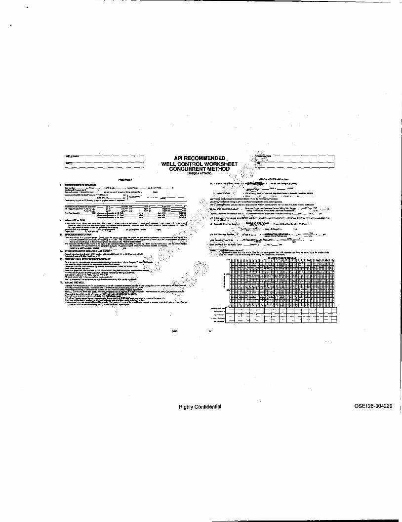
API RECOMMENDED WELL CONTROL WORKSHEET
CONCURRENT METHOD (SUB$EA ATTACIC)
IfJAF;_.~~.;,!, r~~ .. JM1<:<IIT"IlrIh>I~UIII~r ~~ __ ~_. !".,~_._._ ... " __ I~Y!tIL--I* D .... (NOl.-" .. ,-~.;;.... : =.;.::.:,:=.::::::":.._ .... ,..." C~jj"_Ipc-.FN:"'. poo/11 __ onp"_.t.aingaoklcl,tlSily", ,., .. "'-_"" __ CmiIot_ ==~~ }~tor. ____ ._ ... ___ _ OcJ.OI~~I2Ii'_"'IIp_,,<..:No_",~
-
I' ',. '"C, _1l62'o< __ 'II'I_lI>'pl __ Ibo.JoIj __ "" .t .............. ...or-__ ...... IrI_ .. GGAt..-v~ ~ ............. "'~'II~n_.".,..,......,~ j!ilj-~~~l_~CIIPOUI_'V.III>IKlIIfI ... -..u..~".,H'*''''''"''tt.<*>dIe.~ ... ,...up ..... ..-\
'1:';"t~'Ii*;;'/~lD>"-- - ~~o!:;-=-a:,.."7::3~ __ P'~_': ._P5I ~_l/I ...... Qr<U ... ~ :_''',_._P'l'~W_A.-~ _____ ~ __ .~P'I-
m !~.,.!"_~._~~~UlIlAIIID\> __ ""_.htIo"9'1otQ"""""m<I?W-'r<JOnl<dm_.
jlJJRl<Jil;tldQltl""IIN~~.-:.,.. ~~ .""-'t.D'IIro:IFbd~~"1t1'pM.t
..•.. _--- .. :~ ':lIS&' ~·ff ........ -.. O'lIn.g.It_ -Mo'~ol _R"'~~~":"(-;': _.ufif .. _ ~ r;:.:a:IrQ"1.Z:= -,,_PtA'. == -_pOi
t~,~,~~~~. -::" 9@P\p!Cp"~8!!!nI!\..!I!!!!! .~===;~",-' . ·inJ~"".~~T""". _rlklbnnx _",~---,"
Highly Confidential OSE 126-004229

API RECOMMENPEP WELL CONTROL WORKSHEET
1- I:: I ..... Pft&f'lIUW:!IY: _______ ---'COMPMY _____ _
~= ~~, I :~: ::: l-r~ ~ ": :: :,:. S'li Hoi lSJO IS:.- Sllrl'l-WIIIiI 31 ,',. !lit.. OGD12l
~:: ~~ 1i: ::~ ::~ : :"~ :::: ... Ell ,'01) t5.8II LF e _ 11110 O.o1N1 f';Ie E.lI , • ., ;i!l'ti I~ SIt '8'", 3f;o1 801." 4',.. le"J 11'. 17,81 1-1-40 • 11:1" -lUll.,. 4'1a I E,U. ,.. ta.81' ;tCH. 48 .'.(,0 ~.lt O.()l3ei1 ,,'/;I !!.u <!lOG 21e2 I.F SO 11;" ".07 (U11m 4'12 I.eU. 3:108 at.(l!ll ~H .. fI'f~ 3Hl O,oU5J t 1£,1). 111. »,. xii. 10 8'1. ~l..os 0.011-48
}~ i:ittJ:::= ~:E~; f' ,E:N :;
-"-mg~!!!!!r.'I1!dI~.~""!':~ .~- <,',
1'!!lfJ~_jb1!!!i;;aQ 1M!!!' ~-~'!W:
~",,"'u!!I!'SI!;:'!I!oW!onb!!! _ ~ A;:.~'i:'~;'· .'wOW ,,_.,_j.
~M&"'8-fIJM !itGlw'?OO;'t'./SiIIApr .... :":.> '",~:\~: 11m. .. _-n DIL.l1IK*OI'~~~I'lPJl~W.m8
• II'twi!Dofti1pN~~J'.~t?!!inpAuijjYpM!e .! ,..~ ~~alr .~ .
& ....
'-... ' .... 11--
;" .. 18" ,,-,-
.'" -- -:: " " .. " to .. .. "
". ;:-, ) , , , , 7 ., · · : •
Highly Confidential
'~'-- o.
~t . .' .. )
~'h , s'n , ,'k ~~~~~,
• ,'k
-:...:- ............ ..,~,D ......... ~ : ..... '-,: .. .fIID9tRenlVDlunMticEMt08lq'j
Dit~(IIIII."'1 .. 0II01J111"L!2!l'-~{a) " JMMr..I. .. .8I/'aIogoo~,'"
D"I..IfW~,in.
,;'-" --.. :.: ... ". ,'~ ... 3 , "-..
-- r -:';"" .. - H :~ • .J'jt
d-Roo::I~ln. fl!VoI'-II\c~dldlrlaI""'" .
"'" -- ~ - ..::=... '"'"'-., .. " · .. .," Ii :';:, .~ .. , " ,'n '" " ,'. T', ..,.
" , ,'. ::! :: ;' "k ,' . '" " · , ,,.
" .. , .. " " , , .. , :: r. ,
.'" · , -". .. , ... '" " o'b ,'n , .. " , ,'. . l! " ,' . "k
a_ "" .. _M' ;l2
'" .. '" -;: .,,, ... .., on ... , <It ,.. ... '" * ~~,~ " • ,'k '" '-'::.,~ ,. .,.
,." &:-, . '. . ... , ,'k . '-k )
~'!z , :"!! ,'k
............ of~ .................. l1ao~Vdlfrnntr:E'fiNJK!y)
n~lbbi'lolk! '" ~~L~o" ~J. ~-Sht....,."""
o U.,.....-- ....
=. -~ .... · := : • · ... " , ... .... • , - · :" .. " · .... " 4~2 ..,,, ,. • .... '" ,'. .... i~ · .- -e.'h - " • -"'" " ... -"'" " • :: ;'11
"'t::"'" .... .-.... ..... ... , .m .-""" .'" .." .... "" ..., ..... "'" .....
OSE126-004230
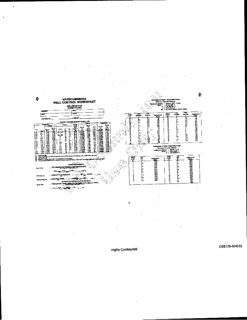
API RECOMMENDED WEll CONTROL WORKSHEET
I:;"' I::
"'" T .. _
'= ...... - ""Er "'I'..'" ,- ....... "'I'..'"
J.l .. ~ u,... ":" <::' - '" "" ~. ""'" ... , ,::,., ""'" No. · ..... ...... .... :ii, '" ;0.'" ,... -- ~ ;,Z .,..
""'" ... .,,, ._, ~=
Eu. " .. 10.'" IF 11\1."4 ,- C.41' "., ,-0" I. 'U' 1$,. -- " ,', 3O'" , ..... ..... m. ..- .... ,'. ElL \3".30 "" ". .. of!}. "' .. ... ,., ".. "" .- . ... 3 J,':I EU. " .. .... " .. · " ... ",,.., .. " "" ...... " .. . <. '"'' . ". IF .. • .". '-' , ... ... ,~ .... ", EU , ...
~~: I.F to ... .. ., C.014't1 H" ,., .- ,-
.'Ii ~~.~. , ... ~ · ""' ~:,= ~:=
11.; ,.-. ...... .;'
.'. " .. 1'.31 .. ,'~ S1.n 11.& . ..... . ... ... ... .... " ... IF " ... "" O.0ftIl7 ' .. 11,3- ... -i.Jl; . ". "'" )(, .. , .. :SUi ,.,,., 1.11'3 , .. .-.', I.cU. ~ , lEU " .. "' .. ~. .. .. ... QII't741\ "" '" 0.007$1 O-'Itil
0 I.E.U. "''' ,. .. ~" " ;" " .. . .,'" TO" ... I~=g:li ," I~U. "" ... " F.H. ~ 31.11
~= .... .. ,
7 "", , .... .. , ,.." " .. F,H. .'·1 5'12 IE.U.
f1J ~E_'" :~ 'I"., ~ =~;J'Ii:~"'lofo..r_~_~~r .... Edi/IIIJl,_~- , _ f'J a..r .... -..,.... ......... <IIl<I ............. ."joIWo ::"':"-"- ','" : .'"
t61 TI!iII~""""W_"~jO""""O!J'II"""""''''~fd'..p~~·,.,.~''''' 8N111'E~,'-'
'~·'!!o9tf!!!!\~i~n~MDPM -' _-",~""""~,,,~_-, ... ,,,,,-,.._~ ... _,,,- ~ _~OOIlbl
DrfI!lQFl""""'1:I<!ooek!'100bb! • --~ •• "'. ,:-.,~~~"'"'r"~"" .. "'''''"-6Ml<U1~d11. _ _ ~ .... _:, It!!- __ aMI'JI
~~~~WlRlWATSI _ g,.m.tlo!I .. p.,tI~~~~C!I· .. PIuocIVp!ur'I!*'
. ~.
~ 7 , , 7 , , , , 7 · · · · ,
Highly Confidential
-.. .. . '. ," ,'. "k ti.'ia , , :1_
'"'" ''', , ftz :'k ,', . f~ ,'. , ,,. . ,',
.... - '- --... · .. '" " · . . ., .. !'Il: .'" " .• 02 " ,'. .". " 7
::: 11 i" .. '" " · .,,. " ,'. ,., "
, .. " "
,. ~." " · M' "
, .," " ~. .'" .. '" : 1'. ... • =
~ofT,..,.......,..,.P .... 11Oo""-'VOluI!lft1o;E~
O~"Slkl·OCIlP3ll.\(d ""'-:l."""'IMgIh.''''
D. Ulllfdianrellt,th - ,-""':!::""" ...... -. .. :: · .. · · ..... · .' . - · · ..., · .'. "''' · · ... " " ... "". " • .... "
,. ..., .. · .... " ... ..... " · .- " .'. ..., " · " ~.
"
......... -. o. . 2',j, '" ,'. n, 2'1. '" ,'. '" ". ,,,. ,. . )T' , ". , .. , .. "" , on , '" ,'k ,., .'. '00 ~;II: '" Sl,. m 1fJ'/1 '"
--:: -.... :: .... ... ' ..". ..,. ., ... .". -"'" .12211 .,."
aSE 126-004232

" 0:, ~.
r~ ,u. E» ,'. Ice ,'. W
!'b '.U EU
~'1lI .. ... L-e-U .'. c<» .'. .. !\~ J.e.U,
1.!.1.I I.E.'" ... I.IE_U ,', I.~IJ
---
API RECOMMENDED WELL CONTROL WORKSHEET
WAIT AND WE1Co11T METHOO (SUBSEA STACK IN DEEP WATER)
j=----" .... _-------
, ' .. - ,= . " ""'" -';:"
I~:.c, ..., - "'" :: NO 0. ... 0,. ~.l\. .. = F~~ t~ ..... .... R -W."" ::: 1-:::- : ~ .. =: .....
~~ ~ =-" .. 30.74 OM, . ...,., "" 'lUG -.... " .". ".eo =: . -.... ...... .... ,e.*I l.\lLn 1.1" . .. .•. ,. ... ; ... 135 .• o.~ OMIII lUG lUll LF • .. , .. .. O.00H1 0.811 .... o.oosoe 0.154 ,A:OO "" IF .. . SUO G.Ofoti ,.,. = :: =:.j:"< .... te .• ,.. .. ... ".., O.l)14tt1 , .... "' .. 118.1 """ :~,.
., .. ..,'" "" 7U' "JlIISirII"~-..... , .. , ... .. 3'1.11 ..., ... , . ." ,,~ O.llOfl6l!l,,'~e.t2J "' .. ~ .. " .., .. .. 31.Q:1 001.m "'" n. g=-'.::: "' .. .. " X •• .. .'~ J.1.11 ..., .. , t."" " . .... "' .. .". .. ~ " .. ..,,,,, , ... 51.' O.oo?lO.: ~o.:R)Il. ..... a .. xo .. .. ... . .,.,. "" .. . !E= t ... '''' " g: , 1111 om, • . .., :t .. " .... ." , 31.1" ,..." , ... ... .... 1IfII!~ ".~::;.
"'1p .. rf!...I!rIl!"'~~U-~~
''''7911.s_W~n:i\1ilbl!iM! _~
MnpRu.tVol,:,:"'hP-'100l>lll .. _~._.:.._ '_. '*r", •• _100tlil ~:,
,:::,:':;;'~~;~t:=!.-(bJI!-si~.--·b!?!
Highly Confidential
'.';
<' ;c.'"
'.~"~, "It · :,,!j f'
" ". .. , " ". :: ~ " S','1
" 1
" T,' to
'. :"~-,~
" ~~. " ,.. "'".; "':~' Til ".
,"'
1-=-.. f , , f , , , , , · , : ·
-~,"b:IpIIol,D~""" .Pen:.nV~~J
~::'~l: ~~-d·](a.) , D .. \.Jfa.rdill!Wllr,lIt.
4_F'tGtf*"""ln. 11ft \\1illlll\riedlrcillncy.~.ilb::lio!o ,. ... ..... ......
""'- ,- ~' -, m,
:.Z .''l' :: · ... :'11 ,'. .f" " ". .f" " 6"'2 ,'. >t, tI , "k .... " ,'. ~'k :~ ~: : , ,,. .. 8';7. ,. .tin " ; 0 ... , " f •
" IS,;' '" .. · t;.: .,,. " · .f" .. ~. .,. , .. " ... :: .. t • .,. " , .. . '"
............ lIl'rdplu, --('«IO'-rrIw...-.v.!MC.encr) ~~(lItJIIIIIL~.~kL .. O'
,-"""l"~IeI9"" D • -lJrW......,. III
....
... ...... , ., 2. 2~ ". ... .." ,'. ~I.
: . , :'1:1 .' . ,.. ,'. ,'.
-.m fO f1, ... "" ..,. ':: ." '" Of ,a12 'OT
'" "" .m ...
=. s:-' ,- .... "'--. · ii . .-, .... · .. -!'ll! ..... · · -.- , ~t" .... ,'. .... • .... • ..... · ". = s" .,.,. · · · .Q81:i! " ". .. ..
~'o\ ., .. " h "" ..... ~~ .". ." .- · "" · - to .'. .f6M
5'.'2 :: " , .• m · " ," .... .. " '"" " · ....
" .'. .~~ " r
OSE126-004234

API American PetrQleuni Institute
2006 Publications Order Form Dale:
I nvolce To (1..1 Chec~ here if same as 'Ship 10")
Name: rrtle:
COmpany:
Department
t~Mail:
Quantity Product Number
GX1QA03
Effective January 1, 2006. API MembelS reoi!I\te a 30% discount where applICable. Tho ""'""'"'<IisoountdqesnatliPlllY"''''' ........ m_forlhe_of .... le .. lor _atlOn trn:> ..... m ...... 0""'010. tr.lning"""" .... __ «other cortun~ ~mtKise$.
AvaHable through Global Engll1eerlng Documents: Phone Orders! ;l~7l19 (TqJI.fJte in the U.S. and canada)
303-397-1956 {locat aM lntema1ionatJ Fax Or~: 303-397-2740 Online orders: www.globaUhs.~.ni .. < ~ "
o API Member (Check if Yes)
ShIp To (UI'S y,flJ n.ot del~~_a'p.w~" Name; "',
Title: Company:
Department:
£~Ma;I:
Uniti:irlc:e Total
$137.00 G07242 ~.!= ',ab .. Choke and Kilt SvstertT9 ' $110.00
G16002
G64Q02
u p.o. No. (En~Q>pYr _,0.....-----
,.', ,'>-
, LJVISA' .J MaS1erCald .J Diners Club U Dbcower
C!edit Card No.:
Print Name (As It~ on CardJ:
EJpi!1l1ion Date:
Highly Confidential
$147.00
$86.00 $110.00
Subtotal 1------1
Applic:able Sales T •• (see below) 1------1
Rush SIJippIng Fee (see below) t----~
Shipping ami Handling/see below) 1-___ --1 Total (in U.s. Dollars} .... --_..1
OSE 126-004235

There's more where this came from.
.,-::.
Tl'le American Petroleum Institute provides additional resources ari~~~ro~~ms to the oil and natural gas industry which are based on API® Stain:l~td~:.For more information, contact: "", ,c
,- "':_"" '.~~f\'o,.
• API Monogram® Licensing Program " """ "'~hrine: 202-962-4791 ""'.J~a~:; 202-682-8070
• American Petroleum Institute Quality R~str~r~.> . (APIQR®) ">'; ,'c:' :,
" - ~ . ,-
• API Spec Q1® Registration
• API Perforator Design Registr;:jtkm'
• API ISOITS 29001 ~~t~i;on'
• API Training}'rOVider ~Certifjcation PrQg~
• IndMdtil Certification Progra~~ " 't.'·,
• t~gif{~ Oil Licensing and,b~rtJt1Cation System (EOlCS)
~" API PetroTEAMTM (Training, Education and Meetings)
Check out the API Publications, Programs, and Services Catalog online at www.api.org.
Highly Confidential
Phone: 202-962-4791 Fax: 202-682-8070
,.,0_'
Phone:' 202-962-4791 ·Ftt'/ ;202-682-8070
'-:-:"
Phone: 202-962-4791 Pax: " 202-682-8070
", Phone: 202-962-4791 Fax: 202-682-8070
Phone: 202-682-8490 Fax: 202-682-8070
Phone: 202-682-8064 Fax: 202-682-8348
Phone: 202-682-8516 Fax: 202-962-4739
Phone: 202-682-8195 Fax: 202-682-8222
API Americen Petroleum Institute
Helping You Get The Job Done R.ight"
OSE 126-004236

Highly Confidential OSE 126-004237

Additional copies are available through IHS Phone Orders: 1-1:100-854-7179 (Toll-free in the U.S. and Canada)
303-397-7956 (Local and International) Fax Orders: 303-397-2740 Online Orders: global.ihs.com
Information about API Publications, Programs and Services is available on 1he web at WWW.api.org
1220 L SlIest. NW Wash! ngton , DC 20005-4070 USA
202.682.8000
Highly Confidential
Product No. G59002
OSE126-004238