590-10 programmable controller - amazon web … · 590-10 programmable controller ... 345 -ˆ ˆ...
TRANSCRIPT

INSTALLATION INSTRUCTIONS
590-10 PROGRAMMABLE CONTROLLER
TABLE OF CONTENTS Section Title Page INTRODUCTION ................................................................................................................................................. 3 COMPUTER REQUIREMENTS........................................................................................................................... 3 INCLUDED HARDWARE & SOFTWARE ITEMS ................................................................................................. 3 HARDWARE CONNECTIONS............................................................................................................................. 3 DOOR CHIME ACTIVATED SYSTEM.................................................................................................................. 7 SOFTWARE INSTALLATION .............................................................................................................................. 8 STARTING DRAGON DROP-IR .......................................................................................................................... 8 SERIAL PORT SELECTION ................................................................................................................................ 8 PROGRAMMING PROCEDURES Planning the System................................................................................................................................... 8 Learning IR Commands.............................................................................................................................. 8 Creating Palettes........................................................................................................................................ 9 Editing and Testing IR Commands............................................................................................................ 10 Getting Source Commands From the Internet........................................................................................... 10 PROGRAMMING THE 590-10 Select Base Unit....................................................................................................................................... 11 Programming IR Commands and Sequences ........................................................................................... 12 Testing Commands and Sequences ......................................................................................................... 13 SAVING AND BACKING-UP FILES ................................................................................................................... 14
Page 2 Model 590-10
© 2002 Xantech Corporation
��������
���
� � �
���������
������������� ���������
������������������
���� ������������������������������������ ����
���� ��������
��������������!��
����������"�#�����$�����%&�'���� �#(���)�*�
�������(��� ����
����� *�*�
���������������!��
��������!��
'��
���%&�'���� �#(���)�*�
��������(���� ������������� *�*�
��������+"��,-� #���������
������ � ���� ��
��������+"��,
��������+"��,
�����������
.)����#�����*#�*���/�
���-���"��"0�������1��
���-���"��"0������-���������������1�������� *�*�
���������������2�����+��������� *�*�
345��-������ 2"��"�������*���*#
��1����������� *�*�
�64�-7����������� 8
�����
�������
���
�����
�����
���� ��
������
��
�
��
��
����
���
����
8
��������(��� ����
��������� *�*�
��%395:;<
��%395:;<
��������=�����*������!��(�
�������
.����#�>�������������.?�%&"%9
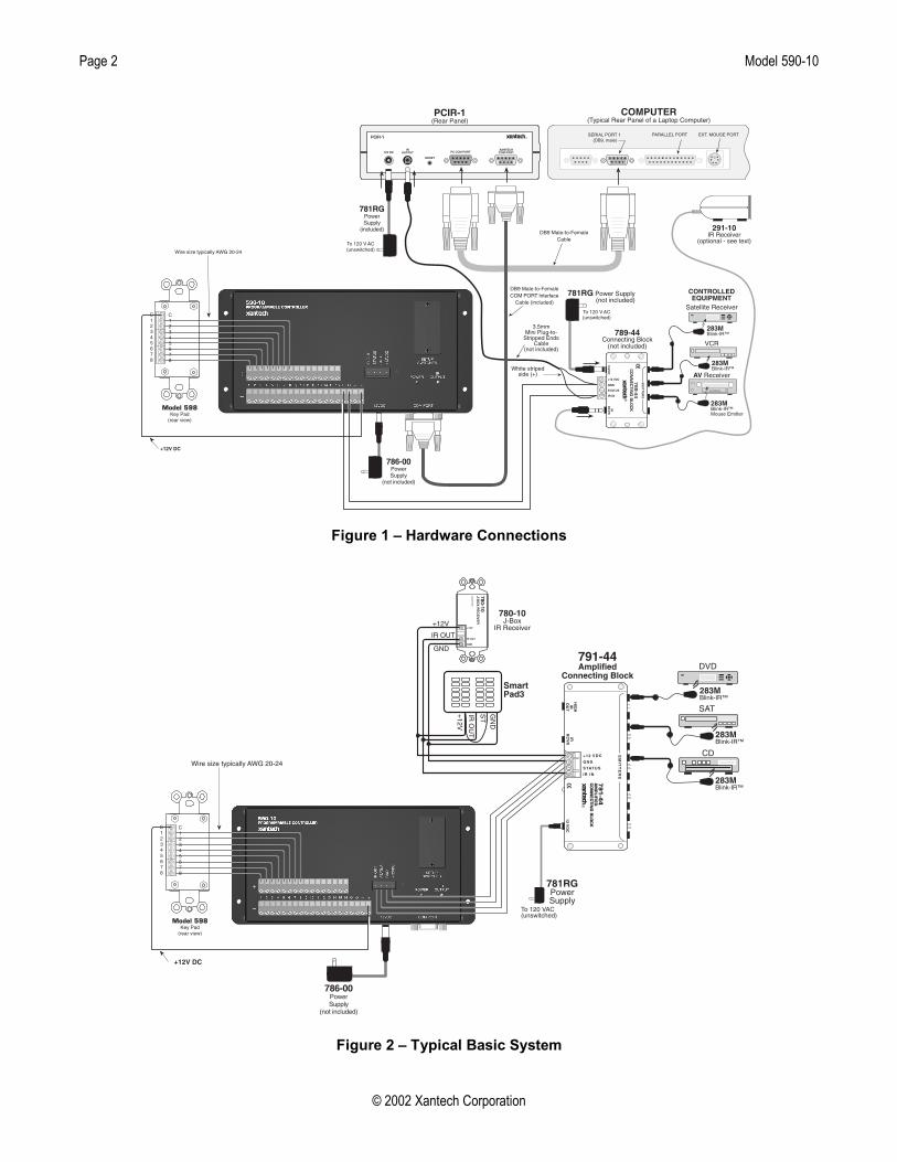
Figure 1 – Hardware Connections
��������(��� ����
��������� *�*�
���%&�'��� �#(���)�*�
�������(��� ����
������� !"#$#%&
�'((%)*#(+�,"')- '
��
��������+"��,
��������+"��,
?@
/�%'������A"��$
��������!��
?@
���7
/�%'
����
����
���
������.�,��� � �� �
6�@��B
� /0*�/&�
�
��� ����
���
���� ��
������
����
���
�����
��� ��
������
���
���������
���������
�������
8
���7
��������+"��,
�
��%395:;<
��%395:;<
��������=�����*������!��(�
.����#�>�������������.?�%&"%9
�������
Figure 2 – Typical Basic System

Model 590-10 Page 3
© 2002 Xantech Corporation
INTRODUCTION The 590-10 gives the custom installer the ability to use any push button or contact closure to initiate IR commands. The 590-10 incorporates 16 isolated input circuits and a learning microprocessor. There are 16 pair of screw terminals on its rear panel for use with up to 16 individual contact closures. The first section of this manual will cover aspects of DRAG460 regarding setup, learning IR codes etc. The following sections will cover the particulars of programming the 590-10. COMPUTER REQUIREMENTS (MINIMUM) • 486 66-MHz IBM® Compatible Computer (Pentium versions preferred) • Windows 95/98/NT/2000/ME/XP • 5 MB Hard Drive space (you will need more as your keypad libraries expand) • 16 MB RAM (32 MB preferred) • Mouse INCLUDED HARDWARE & SOFTWARE ITEMS To use the DRAG460 beta program, you will need the following items included with Dragon Drop-IR™. (See Installation instructions DD4 v 4.1.3 for use of other parts and connectors.) 1. CD ROM Disc. Contains the Dragon Drop-IR software, plus IR Code and Product files. 2. One DB9 Male-to-Female Cable. Connects to the Com ports on the 590-10, a PC or PCIR for programming. HARDWARE CONNECTIONS 1. Connect all of the hardware together using the cables provided. Refer to Figure 1. 2. Connect the OUTPUT of the 590-10 to be programmed to the product to be controlled to test commands.
Figure 2 shows connections to a typical basic system. 3. Figure 1 also shows a 291-10 IR Receiver as an optional item. You could use this to test IR commands on
the controlled equipment through the IR system before they are learned and programmed by Dragon Drop-IR, if programming IR.
Setup Switches 1. Write/Protect Switch. Up is ‘Write’, Down is ‘Protect’. Must be in ‘Write’ position for programming. Protect
position prohibits programming and protects all stored data from unintentional erasure. 2. Network Address Switch. Has no function in this product. Should be left in factory default ‘0’ position. 3. Restore Switch. Resets unit to restart operation after errors, lockups, etc. Does not erase user programmed
commands. Inputs A decision as to the type of external input(s) must be made. Figures 2, 4, 7 and 8 show some examples. The LED inside each opto-isolator within the 590-10 must pass current in order for the unit to recognize an input. This is accomplished by applying a 5 to 30-volt DC input to these 16 circuits. While many types of switch closures to do this are possible, Figure 2 shows the 598 providing contact closures to activate 8 of the 16 opto-isolator inputs. Note that internal jumpers are factory configured so that the negative input terminals are grounded. Input Connections Each input circuit is connected to two screw terminals, one marked + and the other -. These terminal pairs are connected to an opto-isolator. A resistor limits the current to 11 milliamperes at 12 volts. A DC input of from 5 to 30 volts will be sensed. Each terminal pair is internally wired to a pair of jumper headers. Units are configured at the factory with a jumper in place connecting the negative (-) terminal to ground so that each input can be switched by connecting one side of the input switch to +12 volts. If desired, the jumper may be removed leaving the input circuits electrically isolated from each other. Or, the jumper can be moved to the header shown as the OPTIONAL POSITION so that each input can be switched by connecting one side of the input switch to a common ground.
Page 4 Model 590-10
© 2002 Xantech Corporation
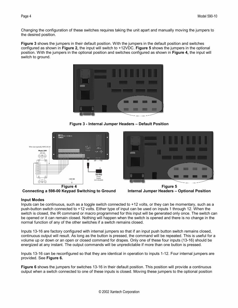
Changing the configuration of these switches requires taking the unit apart and manually moving the jumpers to the desired position. Figure 3 shows the jumpers in their default position. With the jumpers in the default position and switches configured as shown in Figure 2, the input will switch to +12VDC. Figure 5 shows the jumpers in the optional position. With the jumpers in the optional position and switches configured as shown in Figure 4, the input will switch to ground.
Figure 3 - Internal Jumper Headers – Default Position
�������(��� ����
��������� *�*�
��%395:;<
��%395:;<
��������=�����*������!��(�
.����#�>�������������.?�%&"%9
�������
Figure 4
Connecting a 598-00 Keypad Switching to Ground Figure 5
Internal Jumper Headers – Optional Position Input Modes Inputs can be continuous, such as a toggle switch connected to +12 volts, or they can be momentary, such as a push-button switch connected to +12 volts. Either type of input can be used on inputs 1 through 12. When the switch is closed, the IR command or macro programmed for this input will be generated only once. The switch can be opened or it can remain closed. Nothing will happen when the switch is opened and there is no change in the normal function of any of the other switches if a switch remains closed. Inputs 13-16 are factory configured with internal jumpers so that if an input push button switch remains closed, continuous output will result. As long as the button is pressed, the command will be repeated. This is useful for a volume up or down or an open or closed command for drapes. Only one of these four inputs (13-16) should be energized at any instant. The output commands will be unpredictable if more than one button is pressed. Inputs 13-16 can be reconfigured so that they are identical in operation to inputs 1-12. Four internal jumpers are provided. See Figure 6. Figure 6 shows the jumpers for switches 13-16 in their default position. This position will provide a continuous output when a switch connected to one of these inputs is closed. Moving these jumpers to the optional position

Model 590-10 Page 5
© 2002 Xantech Corporation
will provide a momentary input and will output the IR command or sequence associated with this switch once per switch closure. NOTE: These jumpers are in staggered order as shown in the detail in Figure 6. Be sure to move the jumper for the appropriate input switch.
Figure 6 – Internal Jumpers
Sometimes it is desirable to have an IR command generated in response to some change or action to trigger automated functions in an audio/video system. For example, if an AM/FM receiver is turned ON manually, an IR command sequence can be made to turn a TV set ON and set the channel to 4 at the same time. When the AM/FM receiver is turned OFF manually, an IR command can also turn the TV set OFF. (If it is not necessary to turn the TV set OFF, the Model 599 Pulsed Switching Module is not required with the Model 590-10. To do this, the presence or absence of a constant ON and OFF DC voltage must be converted to momentary pulses to properly operate the Model 590-10. This can be done by using the Model 599 Pulsed Switching Module, connected as shown in Figure 7.
Page 6 Model 590-10
© 2002 Xantech Corporation
11
�
���
����
����
���2
���
����
������������������ ���
������
�C�-�������D�-� ���@�74�4�4�
�%&�'���0������(���)�*�� ���
��
�������
��������(���� �����-�#��5�����%�'� � ���2 ����*���(��# �����#�(����(��+�
.)���������*���*�
������������������2�����+�����4 ���%&�'���7�#(���)�*
���������(��� ����
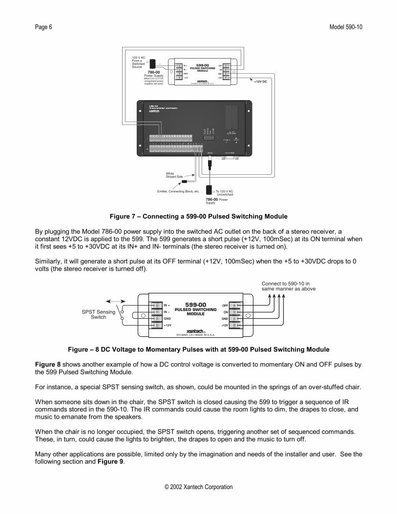
Figure 7 – Connecting a 599-00 Pulsed Switching Module
By plugging the Model 786-00 power supply into the switched AC outlet on the back of a stereo receiver, a constant 12VDC is applied to the 599. The 599 generates a short pulse (+12V, 100mSec) at its ON terminal when it first sees +5 to +30VDC at its IN+ and IN- terminals (the stereo receiver is turned on). Similarly, it will generate a short pulse at its OFF terminal (+12V, 100mSec) when the +5 to +30VDC drops to 0 volts (the stereo receiver is turned off).
11
�
���
����
����
���2
���
����
������������������ ���
������
�C�-�������D�-� ���@�74�4�4�
�����������5�&"�&���#������������#��1�!�
�������#��2�(���)
Figure – 8 DC Voltage to Momentary Pulses with at 599-00 Pulsed Switching Module Figure 8 shows another example of how a DC control voltage is converted to momentary ON and OFF pulses by the 599 Pulsed Switching Module.
For instance, a special SPST sensing switch, as shown, could be mounted in the springs of an over-stuffed chair. When someone sits down in the chair, the SPST switch is closed causing the 599 to trigger a sequence of IR commands stored in the 590-10. The IR commands could cause the room lights to dim, the drapes to close, and music to emanate from the speakers. When the chair is no longer occupied, the SPST switch opens, triggering another set of sequenced commands. These, in turn, could cause the lights to brighten, the drapes to open and the music to turn off. Many other applications are possible, limited only by the imagination and needs of the installer and user. See the following section and Figure 9.

Model 590-10 Page 7
© 2002 Xantech Corporation
DOOR CHIME ACTIVATED SYSTEM The circuit below, Figure 9, shows a simple means of using a door chime or door bell to activate one of the inputs on a Xantech Model 590 Programmable Controller, to initiate a system function or functions. Functions that may be initiated by this system, might include the following: • Switch the AV system source selector to a front door surveillance camera. • Turn on front door intercom. • Mute the audio in an A/V system. The circuit uses a rectifier and a zener regulator to take the 24 to 28 volts AC from the chime coil and convert it to the necessary 12 volts DC to drive the input on the controller.
�@��9
�������������)�������������*�*�!����
��=��)����E9�.
�%�'���F����
��G0*5&�'
�%&�'���
�%&�'��
�)��������
�)���������#������ �����)���
� #)1 ����
�(���)�#0���)����#��� �!���#
����������H���2 ���������� ��
���������� ������������ �������)���
�������������#��#�#)�(�
/
;<:"&&���(��� ����
.)���������*���*�
Figure 9 – Door Chime Activated System To implement this circuit, proceed as follows: 1. Build the circuit using the parts shown. 2. Place the assembled parts in a small metal box. 3. Connect the input of the circuit to the chime coil terminals as shown. Note: Do not connect it to the door chime push-button terminals! 4. Program the 590 with the necessary remote commands to drive the controlled components. Caution: Do not connect this circuit to any other terminals on the 590 except the pair of input terminals you wish to assign to it!

Page 8 Model 590-10
© 2002 Xantech Corporation
SOFTWARE INSTALLATION The installation software for the Dragon Drop-IR system is included in the supplied CD ROM. Install the Dragon Drop-IR™ Software onto your hard drive as follows: Windows 95/98/NT/2000/ME/XP 1. Insert the DRAG460 beta CD into your CD-ROM drive. If your drive has been set for auto run, a ‘Xantech
Welcome’ menu will appear. If not, access your CD ROM with Windows Explorer and double click "autorun.exe".
2. On the Welcome menu, click Install DD4 Software. Follow the on-screen instructions as the program installs. It takes approximately one to three minutes to complete, depending on the speed of your machine. NOTE: For the convenience of the installer, the Dragon Drop-IR CD ROM contains a complete set of Application Notes, the Xantech Product Catalog, Factory Learned IR Codes, web site browsers and important notes. Read the Very Important Notes first, click on the desired menu item and follow the on-screen instructions.
STARTING DRAGON DROP-IR Windows 95/98/NT/2000/ME/XP 1. Installation creates a shortcut on the desktop. Double click on the 590-10 Shortcut or: 2. From START menu, choose Programs. 3. Select DRAG460 from the list and click on the DRAG460 Icon. 4. The program loads and opens to the Xantech Dragon Drop-IR opening screen. SERIAL PORT SELECTION When first launched, the Dragon Drop-IR software scans the serial ports and will display the available ports under "Preferences" in the File menu. Unavailable ports will be grayed out. Com Port 1 would normally be used, but if it is already in use, it will be necessary to use a different one. If your computer only has a USB connection, a USB to Serial Adapter (including software) can be purchased at most computer stores and is available for purchase from Xantech. (Also check with local Authorized Xantech Distributor). Select the Com Port as follows: 1. Click Preferences (F2) from the File menu. 2. Click on an available port, then OK. PROGRAMMING PROCEDURES PLANNING THE SYSTEM Before attempting any programming, plan the system configuration first. This should include the following: a) Determine the brands and types of all IR-controlled components you expect to use.
CAUTION: See caution card (included) for the latest information regarding code compatibility before finalizing the system.
LEARNING IR COMMANDS
NOTE: Before starting this section, palettes created in other versions of Dragon Drop-IR can be Copied and Pasted to the PALETTE FOLDER in DRAG460 beta.

Model 590-10 Page 9
© 2002 Xantech Corporation
Figure 10 - Brands Figure 11 - Components Figure 12 - Palette Editor
1. From the “COMPONENT” menu, click “PALLETTE EDITOR”. 2. Locate and Select (single click) the desired BRAND as shown in Figure 10 (i.e. Sony, Panasonic etc). A list of
Components will appear. (See later sections for adding brands.) 3. Locate and Select (single click) the type of COMPONENT as shown in Figure 11 (DVD, SAT etc) (See later
sections for adding types). 4. The Palette Editor will now be open to the “Brand” & “Component” selected. A list of FUNCTIONS for that
type of component will appear as shown in Figure 12. (See later sections for adding functions). 5. Click on the RECORD button in the middle of the Palette Editor. The RECORD button will turn red. Dragon is
now ready to learn the IR codes for the specific brand/component selected. NOTE: Once in record mode, or any mode in Palette Editor, it is not necessary to select RECORD, or any
other mode again, until leaving that mode. 6. Select the command from the left side of the Palette Editor (i.e. Power, Play, Stop etc.). 7. Hold the component remote about one inch from the PCIR IR Sensor on the front of the PCIR. 8. While continuing to keep the component remote about one-inch from the PCIR, press the corresponding
command button on the component remote. A red asterisk (*) will appear to the left of the selected function indicating that an IR code has been learned.
NOTE: If you wait longer than ten seconds, a “NO IR RECORDED” message will appear. Click “OK” and try again.
9. Repeat steps 6 thru 9 for all of the functions to used for that component. 10. With the PCIR connected to the Connecting Block as shown in Figure 1, select “TEST” in the Palette Editor.
The TEST button will turn red. a) Click on each of the command names , one-by-one, that are to be tested. A red dot will flash just to the
left of “TEST” as the IR command executes. b) The controlled component should respond to each command sent.(i.e. “Power” turns the component ON
or OFF, “PLAY” plays the content etc.) NOTE: Only functions with an asterisk will execute. b) If a component does not respond to a command, re-learn and re-test the IR command until the
component responds. CREATING PALETTES 1. After Dragon has learned the commands for that Component, select “ADD>>”. The ADD button will turn red. 2. Click on a function (i.e. PLAY) to be added to the palette. A window “NEW PALETTE” will open. Type in a file
name i.e. PIONEERCD and click “SAVE”. 3. “PLAY” will appear in the PIONEERCD.pal window with a red asterisk. 4. Click on all functions to be added to PIONEERCD.PAL 5. Click the “CLOSE” button on Palette Editor. Palette Editor will close. PIONEERCD.PAL will be saved to the
hard drive. 6. Repeat 1-10 in ‘Learning IR Commands’ and 1-5 in ‘Creating Palettes’ for all components to be used.

Page 10 Model 590-10
© 2002 Xantech Corporation
EDITING AND TESTING IR COMMANDS If a brand, component or function is not found in Palette Editor, each can be added as follows: Adding Brands 1. If the brand you need is not already on the list, choose the Component menu and click on “ADD BRAND”. 2. Type brand name and press enter on the keyboard or click OK. 3. The new name is added and saved to the list. Adding Components and Functions 1. If the component you need is not already on the list, choose the Component menu and click on “ADD
REGULAR COMPONENT”. 2. Type component name and press enter on the keyboard. 3. Type the name of a function for this new component in the text box and press enter on the keyboard to save
new function. 4. Repeat step 3 for all functions required for the new component. 5. Press “Esc” on keyboard to save and exit. 6. New Brands, Components and Functions can now be selected and programmed in Palette Editor. Other Editing Functions • Help. Gives basic help information for the Palette Editor. • Close. Closes the Palette Editor when you have finished editing. Auto-save feature saves all IR commands
and created palettes. • To access the Delete, Rename and New Function attributes, right click within the list of commands. A pop-
up menu showing each of the above appears. • For Delete and Rename, right click the desired command first, then left click either Delete or Rename and
follow the prompts. • For New Function, right click within the list, then left click New Function. Follow the prompt. When finished,
click the Close button. Any changes will be saved automatically. GETTING SOURCE COMMANDS FROM THE INTERNET Xantech.com There are some IR commands that can be difficult to learn in Dragon. Xantech edits and posts some of these commands at xantech.com under Products/IR Code Libraries. (See website for listings and download instructions.) A direct link to xantech.com can be found in the “Links” option in the Dragon menu bar. Remote Central.com There is a second option for on line IR codes. remotecentral.com provides an almost unlimited resource of IR commands. The code files at Remote Central are not directly compatible with Dragon Drop-IR and therefore need to be converted for use with Xantech software. 1. Click “LINKS” in DRAG460. 2. Click on Remote Central Website. Your browser will open and take you to Remote Central.com. 3. Click Files in Remote Central. 4. Click Philips Pronto & Marantz RC5000. 5. Scroll and click on desired brand under "Component Configurations" (CCF files). 6. Click on component type (CD players, VCR's, etc.). 7. From the list find a Model Number the same as your model or one similar to it. (Even model numbers
considerably different than yours will usually have commands that work). 8. Click on DOWNLOAD (this may take a few seconds), then select Save it to disk, then OK. 9. In the Windows ‘Save As…’ pop-up, Open the ccf folder within the Drag460 folder (if not already open). Click
Save. 10. In DRAG460, click Import CCF from the File menu. 11. Find the ccf folder in which you saved the file and click on file name.
NOTE: At this point, prior to opening it, you may wish to change the file name (e.g., RCA-DSS, etc.) for easier recognition later. You may wish to do this in step 13 as well.
12. Click Open. This unzips the file and DRAG460 automatically places it in a folder within the ccf folder. 13. Click on file name, then on Open. At this point, the CCF file is converted to DRAG460 format.

Model 590-10 Page 11
© 2002 Xantech Corporation
14. On pop-up (CCF Importer), type in Brand Name and Component Name (e.g., RCA and DSS). 15. Double click on desired component type on list of converted files on left side of pop-up (e.g., DSS.cnv). An
asterisk (*) will appear just to the left. Click Import. 16. Click OK for addition to Brand List (if shown) and OK for addition (or merge) to a .bci file. This completes the file import to the Brand and .bci files in DRAG460. 17. At this point, or at any later date, you can choose additional component types from the CCF file (e.g., DVD,
etc., if listed) by using the CCF Importer again. Simply click Import CCF from the File menu, double click on desired folder and repeat steps 13 to 16 as necessary.
PROGRAMMING THE 590-10 SELECT BASE UNIT With the system operating and the Dragon Drop-IR open proceed as follows: 1. Choose “NEW PROJECT” from the File menu. (Choose Open Project to modify an existing project file). 2. In the New Project window, type a file name such as “joneshome” and click “SAVE”. The proper file extension
is added automatically. 3. From the Base Unit menu, select “590-10”. 4. A graphic window (590-10) with 16 virtual switch pairs and a Command List will appear (Figure 13). NOTE: Clicking the “OPTIONS” button will open a window that shows the configuration of the internal jumper
settings for switching to +12V or Ground and Momentary or Toggle as described in section “Hardware Connections/Inputs”. This window is for reference only. The actual jumper changes must be done manually by taking the 590-10 apart.
Figure 13 – 590-10 Base Unit
Page 12 Model 590-10
© 2002 Xantech Corporation
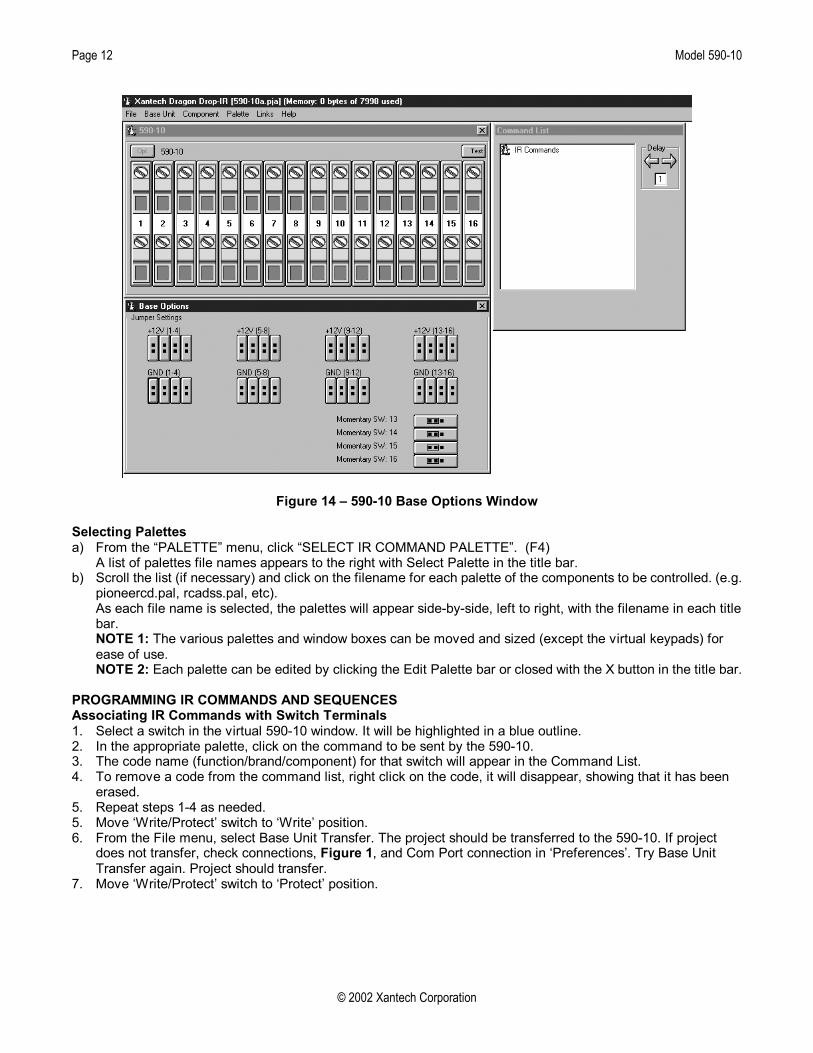
Figure 14 – 590-10 Base Options Window Selecting Palettes a) From the “PALETTE” menu, click “SELECT IR COMMAND PALETTE”. (F4)
A list of palettes file names appears to the right with Select Palette in the title bar. b) Scroll the list (if necessary) and click on the filename for each palette of the components to be controlled. (e.g.
pioneercd.pal, rcadss.pal, etc). As each file name is selected, the palettes will appear side-by-side, left to right, with the filename in each title bar. NOTE 1: The various palettes and window boxes can be moved and sized (except the virtual keypads) for ease of use. NOTE 2: Each palette can be edited by clicking the Edit Palette bar or closed with the X button in the title bar.
PROGRAMMING IR COMMANDS AND SEQUENCES Associating IR Commands with Switch Terminals 1. Select a switch in the virtual 590-10 window. It will be highlighted in a blue outline. 2. In the appropriate palette, click on the command to be sent by the 590-10. 3. The code name (function/brand/component) for that switch will appear in the Command List. 4. To remove a code from the command list, right click on the code, it will disappear, showing that it has been
erased. 5. Repeat steps 1-4 as needed. 5. Move ‘Write/Protect’ switch to ‘Write’ position. 6. From the File menu, select Base Unit Transfer. The project should be transferred to the 590-10. If project
does not transfer, check connections, Figure 1, and Com Port connection in ‘Preferences’. Try Base Unit Transfer again. Project should transfer.
7. Move ‘Write/Protect’ switch to ‘Protect’ position.

Model 590-10 Page 13
© 2002 Xantech Corporation
Programming Sequences All switches on the 590-10 can be programmed to send a single IR command or IR sequences of up to 40 commands. 1. Click the switch to be programmed. 2. Open all palettes to be used in the sequence. 3. In the palettes, click on the commands in the order of the sequence to be sent. 4. The code names (function/brand/component) for that switch will appear in the order selected in the command
list. 5. To remove a code from the command list, right click on the code, it will disappear, showing that it has been
erased. Editing Sequences 1. The Command List can be edited by dragging and dropping any command on the list to any position on the
list. Left click and drag the command to be moved. As you drag upward and you want the command between two existing commands, drop it on the lower one. As you drag downward, drop it on the upper one.
2. You can delete any command on the list by Right Clicking on the command. Timed Delays 1. Timed delays can be placed in a sequence. Click the left < and right > arrows under “DELAY” in the
Command List window for the number of seconds you want (i.e. 2 = 2 seconds). 2. Double Click within the “Delay” outline. This will place the delay at the end of the Command List and the delay
time appears on the list (e.g., Delay 2 Sec). 3. Left Click and Drag the “Delay 2 Sec” line and drop it between any two commands you have placed on the
Command List. 4. From the File menu, select Base Unit Transfer. The project should be transferred to the 590-10. If project
does not transfer, check connections, Figure 1, and Com Port connection in ‘Preferences’. Try Base Unit Transfer again. Project should transfer.
TESTING COMMANDS AND SEQUENCES From Dragon Drop-IR 1. With the PC connected to a PCIR, a connecting block and components as shown in Figure 1, select the
“TEST” button in the virtual 590-10 window. It will be highlighted in red. 2. In the virtual 590-10 window, click the button for the IR command to be used to trigger the IR sequence in the
590-10. 3. The IR command or sequence shown in the Command List for that button will be sent out the PCIR IR output
to the components to be controlled. 4. Make any changes to the sequence as needed. From The 590-10 1. With the 590-10 connected to an emitter or connecting block (as needed given the number of components to
be controlled), and with all switches properly connected to the appropriate terminals, close the switches, one at a time, to trigger the 590-10.
2. The 590-10 should output the proper IR commands to the components. 3. Make changes to the sequences as needed in Dragon and transfer the project again. 4. Repeat steps 1-3 until all controls are proper.
Page 14 Model 590-10
© 2002 Xantech Corporation
SAVING AND BACKING-UP FILES Automatic Save When working on a project in Dragon, it is automatically saved on a continuous basis, It is OK to quit a project at any time and come back to it for further work by simply clicking on Open Project (Ctrl+O) from the File menu and double clicking the filename in the list. Save Project As To create a variation of a project without having to reprogram everything from scratch, i.e. Change “Jones” project to “Smith” project: 1. Click “SAVE PROJECT AS” Ctrl+S from the File menu. 2. SINGLE CLICK on the project file name to ‘Save As’. 3. Type in the new Project File Name (e.g. Smith) and click OK. 4. If there are no changes to the system (type of sources, brand of sources, zone configuration etc.) transfer the
project. If there are any changes to be made, modify the new project and then transfer to the MAC1. Backing-Up Project Files It is always wise to backup all project files to another hard drive, floppy disc or other storage media. It is recommended that each project be saved to a floppy disc and kept with each client's job files. To make backup copies, proceed as follows: 1. Open the hard drive icon from "My Computer" (usually drive C:) in Win 95/98/NT/2000/XP. Open the
DRAG460 beta folder, then the Projects folder. 2. Locate project files. The files in the Projects folder will have .pja,.pjb, .pjc extensions. All three must be
copied. 3. Open a window for the backup drive and make a Projects folder for that drive. 4. Click and drag the files to be backed-up that are in the Projects folder on the main hard drive and drop them
into the Projects folder in the backup drive. NOTE 1: Project files can be relatively large, requiring up to 1 MB of space or more, depending on the
complexity of your project. When backing up to 1.44 MB floppies, you may need one floppy for each Project. NOTE 2: these file sizes can be reduced dramatically, if needed, by using a good file compression program,
like Win Zip. Using Backup Files To use backup files at a later date, copy them back to the Projects folder in the DRAG460 beta directory (after un-Zipping them, if previously Zipped). Proceed as follows: 1. Locate the Projects folder on the main and backup drives. 2. On the backup drive open the Projects folder and identify the files needed, with the proper extensions. Un-Zip
them, if previously Zipped. 3. Click and drag these files from the backup drive and drop them into the Projects folder on the main hard drive. Backing-Up SmartPad and Palette Files The SmartPad and Palette folders in the DRAG460 directory contain all the files of learned individual IR commands and specific palettes that have created for all projects. These should be backed up in the event of a hard drive failure, for transferring work to another computer, etc. Back-up these files to another hard drive, a tape drive or a floppy. Proceed as follows: 1. Open the hard drive icon from "My Computer" (usually drive C:) in Win 95/98/NT/2000/XP. Open the
Drag460 folder. 2. Locate the SmartPad and Pallets folders. 3. Click and drag (copy) the SmartPad and Pallets folders to the backup drive. These files are small enough to
easily fit on one 1.44 MB floppy. 4. To use them at a later date, drag & drop them back into the appropriate SmartPad or Palette folder on the
main hard drive NOTE: To avoid the potential loss of work, back up files frequently.

Model 590-10 Page 15
© 2002 Xantech Corporation

XANTECH CORPORATION 12950 Bradley Avenue, Sylmar CA 91342-3829
phone 818.362.0353 • fax 818.362.9506 www.xantech.com
Part No. 08901650 Rev A 03-13-2002