5900-bt carbon backwash filter installation & maintenance ... · 5900-bt carbon filter...
TRANSCRIPT

5900-BT Carbon Backwash Filter Installation & Maintenance Guide Thank you for purchasing a Clean Water System!
With proper installation and a little routine maintenance your system will be providing chlorine-free water for many years.
Please review this manual entirely before beginning to install your system, and follow the steps outlined for best results.
Minimum 30 PSI required. Maximum pressure 90 PSI. For indoor installation. Protect from sunlight, rain, and freezing. CARBON MEDIA CONTAINS DUST. USE PAPER MASK AND VENTILATE TO AVOID BREATHING DUST. OK to wet down media with spray bottle FOR USE ON MUNICIPALLY-TREATED, OR DISINFECTED WATER ONLY. IF USING ON UN-CHLORINATED OR NON-DISINFECTED WATER INSTALL A UV STERILIZER AFTER UNIT.
Helpful Videos:
https://www.youtube.com/channel/UC415QpvlRz-YAntxlMieI2w/videos
Questions?
Call us toll-free: 1-888-600-5426 or 1-831-462-8500
Email us: [email protected]
See more information on our website: www.cleanwaterstore.com/resources
Clean Water Made Easy
www.cleanwaterstore.com

Table of Contents Packing Lists ................................................................................................................................................................... 3
How Your Carbon Backwash Filter Works ..................................................................................................................... 4
System Installation Steps Overview............................................................................................................................... 5
Pre-Installation .............................................................................................................................................................. 5
Best Practices for Piping & Drain Installation ................................................................................................................ 6
Diagram of Typical Installation Well Water ................................................................................................................... 7
Diagrams of Typical Installation City Water................................................................................................................... 7
Add Filter Media and Install 5900-BT Backwash Valve on Tank .................................................................................... 8
Attach the Bypass ........................................................................................................................................................ 10
Electrical Connections ................................................................................................................................................. 10
Install 9V Battery (not included) .................................................................................................................................. 10
Piping Installation ........................................................................................................................................................ 11
Program Your Valve: Main Menu ................................................................................................................................ 12
Program Your Valve: Master Programming Mode ...................................................................................................... 13
See Historical Data and Real Time Flow Rate .............................................................................................................. 14
Detailed Steps to Starting Up Carbon Backwash Filter System ................................................................................... 14
Installing and Using the Optional Legacy View App .................................................................................................... 16
How to Start A Manual Backwash ............................................................................................................................... 20
Carbon Backwash Filter Maintenance ......................................................................................................................... 21
Troubleshooting Chart ................................................................................................................................................. 21
Error Codes .................................................................................................................................................................. 22
Pressure Loss from Inadequate Backwash Flow Rate.................................................................................................. 22
Problems with Pressure Loss or Reduced Flow ........................................................................................................... 23
Service Instructions – Perform Before Doing Any Service ........................................................................................... 23
How to Replace Powerhead ........................................................................................................................................ 23
How to Replace Piston Assembly ................................................................................................................................ 24
How to Replace Seals and Spacers .............................................................................................................................. 25
How to Replace Meter ................................................................................................................................................. 25
How to Replace the Carbon Filter Media .................................................................................................................... 26
Valve Body Assembly S900-BT ..................................................................................................................................... 27
Control Valve Assembly 5900-BT ................................................................................................................................. 28
Water Filters Limited Warranty ................................................................................................................................... 29

5900-BT Carbon Filter Installation & Maintenance Guide
Page 3 www.cleanwaterstore.com Rev 111918
Packing Lists All systems include: 5900-BT control valve; bypass assembly with 1” connector yoke; power supply; media funnel for adding the carbon media; top screen.
Find Your Size System to See What is Included:
What to Do if Your Tank is Not Level Out of the Box:
Your black filter tank base is not glued to the bottom of your tank. Occasionally tank bases will become crooked during shipment.
If you find that that your tank does not sit level on the floor, you can easily adjust it by holding the empty tank and knocking or tapping it on a concrete or solid floor once or twice to level it.
Carbon Filter 0.75 cubic foot size 8” x 44” filter tank with distributor tube 8 lbs. filter gravel 0.75 cubic foot of activated carbon. Carbon Filter 1.0 cubic foot size 9” x 48” filter tank with distributor tube 12 lbs. filter gravel 1 cubic foot of activated carbon Carbon Filter 1.5 cubic foot size 10” x 54” filter tank with distributor tube 16 lbs. Filter gravel 1.5 cubic foot of activated carbon
Carbon Filter 2.0 cubic foot size 12” x 52” filter tank with distributor tube 20 lbs. filter gravel 2.0 cubic foot of activated carbon Carbon Filter 2.5 cubic foot size 13” x 54” filter tank with distributor tube 35 lbs. filter gravel 2.5 cubic foot of activated carbon Carbon Filter 3.0 cubic foot size 14” x 65” filter tank with distributor tube 50 lbs. filter gravel 3.0 cubic foot of activated carbon
5900-BT Carbon Filter Installation & Maintenance Guide
Page 4 www.cleanwaterstore.com Rev 111918
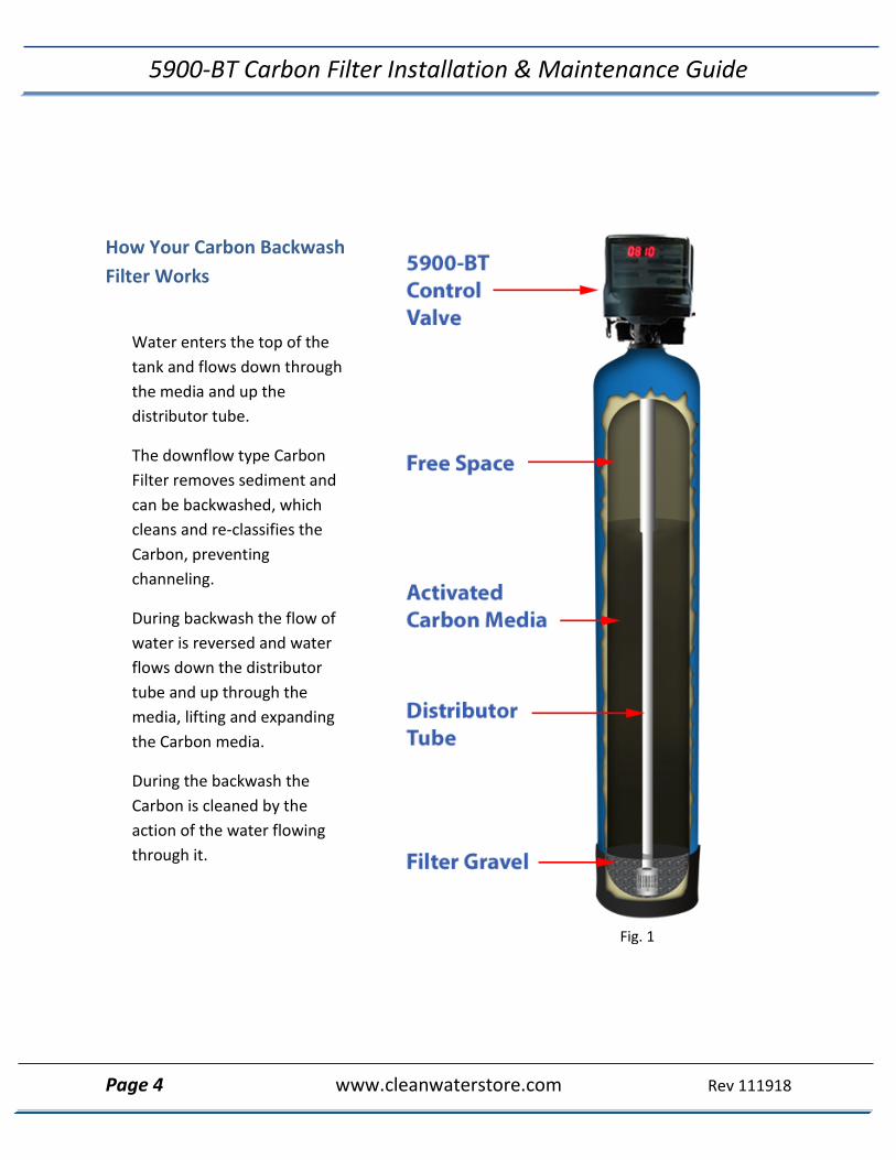
How Your Carbon Backwash Filter Works
Water enters the top of the tank and flows down through the media and up the distributor tube.
The downflow type Carbon Filter removes sediment and can be backwashed, which cleans and re-classifies the Carbon, preventing channeling.
During backwash the flow of water is reversed and water flows down the distributor tube and up through the media, lifting and expanding the Carbon media.
During the backwash the Carbon is cleaned by the action of the water flowing through it.
Fig. 1

5900-BT Carbon Filter Installation & Maintenance Guide
Page 5 www.cleanwaterstore.com Rev 111918
System Installation Steps Overview 1. Verify that you have received all parts and there are no damaged or missing parts.
2. Put gravel in first, then carbon. Fill tank with clean water. The longer it soaks while you
are doing everything else, the better.
3. Make the plumbing connections from your existing system to the bypass assembly, installing extra valves, unions, pressure gauges and hose bibs as needed.
4. Attach the control head to the tank, and to the bypass assembly.
5. Install the Drain Line tubing and Drain Line Tubing Flow Control button (Internal for models 2.0 CF and less, or External flow control assembly for models 2.5 CF and greater)
6. Plug in the power supply and program the valve.
7. Follow the instructions to put the system online and to verify the system is leak-free.
Pre-Installation 1. Review your packing list to make sure you have received all the parts before
installation.
2. If you are going to be turning off the water to the house and you have an electric water heater, shut off the power to the water heater before beginning installation.
3. Pick a suitable location for your filter system on a dry level spot where it won’t be
exposed to freezing temperatures, direct sunlight, wind or rain.
4. Get all of your plumbing parts together before beginning installation.
5. After the system is installed and running, your water may be discolored, or full of sediment or rust, especially if you have older or corroded piping. This typically clears up over a day or two.

5900-BT Carbon Filter Installation & Maintenance Guide
Page 6 www.cleanwaterstore.com Rev 111918
Best Practices for Piping & Drain Installation
1. See typical installation (Fig 2). The Carbon Backwash filter is installed after pressure tank.
2. Install on a level floor or surface.
3. Filter system must be installed at least 10 feet ahead of inlet to water heater to prevent damage due to back-up hot water or use a check valve to prevent hot water back-up.
4. DO NOT install the unit in an area of direct sunlight or expose to freezing.
5. Locate the unit near an unswitched, 120 volt / 60 Hz grounded electrical outlet.
6. Filter system must be installed at least 10 feet ahead of inlet to water heater to prevent damage due to back-up hot water or use a check valve to prevent hot water back-up.
7. DO NOT install the unit in an area of direct sunlight or expose to freezing.
8. Locate the unit near an unswitched, 120 volt / 60 Hz grounded electrical outlet. 9. Make sure to connect the IN pipe to the 5900-BT inlet and the OUT pipe to the outlet.
10. Make sure there is a working gate or ball valve before the 5900-BT Carbon Filter and also one after as shown in Fig 2. The pressure gauges are optional. A hose bib (which is a faucet that you can attach a garden hose to) is strongly recommended after the 5900-BT Filter and before the second ball valve, for rinsing and sampling water.
11. If you will be using copper piping, do not sweat the copper pipe directly on to the 5900-BT control valve. Avoid heating up the 5900-BT control valve plastic with the torch.
12. You do not need unions to install your 5900-BT control valve. If you need to remove it, the 5900-BT has quick-release couplings that make it easy to put the filter on by-pass and remove the filter system from the piping.
13. The drain line tubing is connected to a drain from the drain outlet using flexible poly tubing. The drain can run up above the control head and out to a drain, although this may require installing a one way, flapper-stlye check valve. Most plumbing codes require an air-gap connection, so that if your sewer or septic tank backs up, it cannot cross connect with the drain tubing (if running tubing into the washing machine drain pipe, for example)

5900-BT Carbon Filter Installation & Maintenance Guide
Page 7 www.cleanwaterstore.com Rev 111918
Fig 2.
Diagram of Typical Installation Well Water
Diagrams of Typical Installation City Water
5900-BT Carbon Filter Installation & Maintenance Guide
Page 8 www.cleanwaterstore.com Rev 111918
Installation of Your System into Copper or Metal Piping Systems
If your new filter system is to be installed in a metal (conductive) plumbing system, i.e. copper or galvanized steel pipe, the plastic components (bypass and connectors) will interrupt the electrical continuity of the plumbing system. As a result, any stray currents from improperly grounded appliances downstream or potential galvanic activity in the plumbing system can no longer ground through the contiguous metal plumbing. Some homes may have been built in accordance with building codes which encouraged the grounding of electrical appliances through the plumbing system. The installation of a bypass consisting of the same material as the existing plumbing, or a grounded "jumper wire" bridging the equipment and reestablishing the contiguous conductive nature of the plumbing system must be installed prior to your systems use. This is simple and easy step to take if you are installing your water treatment system into copper piping. A simple ground jumper wire with a pipe clamp can be purchased at any Home Center, or hardware store etc. for a few dollars.
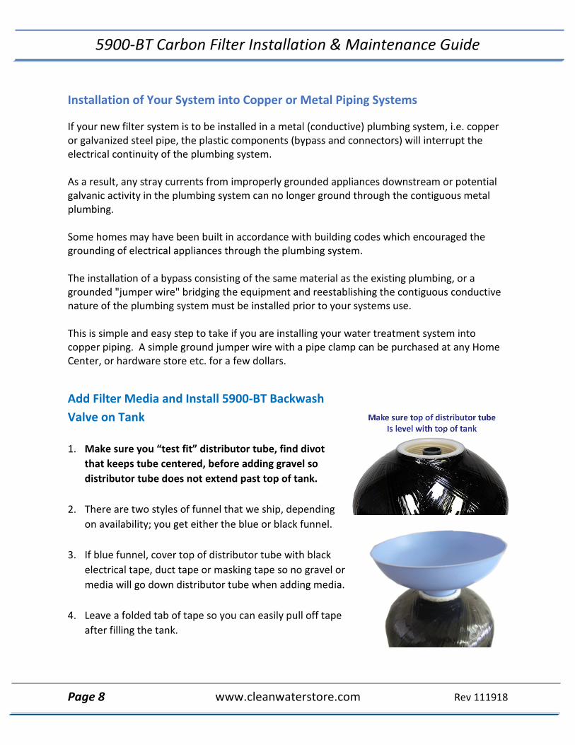
Add Filter Media and Install 5900-BT Backwash Valve on Tank 1. Make sure you “test fit” distributor tube, find divot
that keeps tube centered, before adding gravel so distributor tube does not extend past top of tank.
2. There are two styles of funnel that we ship, depending on availability; you get either the blue or black funnel.
3. If blue funnel, cover top of distributor tube with black electrical tape, duct tape or masking tape so no gravel or media will go down distributor tube when adding media.
4. Leave a folded tab of tape so you can easily pull off tape after filling the tank.

5900-BT Carbon Filter Installation & Maintenance Guide
Page 9 www.cleanwaterstore.com Rev 111918
5. Hold the tube center until there is enough gravel and media to support the tube. The top of the distributor tube should be level with the top opening of the filter tank.
6. Add the filter gravel that came with your order. The gravel should cover the bottom
distributor screen before adding the Carbon filter media.
7. Next add the Carbon Media.
8. The tank should be about 2/3 full of media, do not fill much more than 2/3 full, even if there is media left over. We ship the correct amount of media to fill your tank for most orders.
9. Fill tank completely with water. Allow to soak for at least 1 hour up to 24 hours before you hook it up to piping.
10. Remove tape from top of distributor tube. Be
careful not to pull up distributor tube. 11. Attach plastic top screen to under-side of the
5900-BT control valve. It is a funnel-shaped plastic screen that snaps on to the control valve and prevents resin from being backwashed out to drain during the regeneration cycles. It may twist on clockwise or counter-clockwise.
12. Screw on Control Valve: Add small amount of silicone grease to both O-rings (only O-rings,
not tank thread) on bottom of control valve and screw on 5900-BT control valve carefully.
13. Do not lubricate tank threads or any other fittings other than O-rings. Do not use pipe-joint compound, vegetable oil, Teflon tape, or Vaseline or greases on tank threads.
14. If you accidentally pull distributor tube up after gravel and media are in tank (upon initial
install or any time after, for service, etc.), it must be re-seated. It is usually possible to do this by spraying water down distributor tube with a garden hose while pushing on end of the tube. If this does not work, you must empty tank completely and start over.
15. Do not hard pipe the drain line with PVC or copper, use flexible tubing. If you use hard
PVC piping for the drain line, you must able to remove the hard drain piping and attach flexible tubing for testing purposes.
16. Make sure the drain tubing is firmly clamped to the barbed fitting with a hose clamp to
prevent leaks or blow-offs.

5900-BT Carbon Filter Installation & Maintenance Guide
Page 10 www.cleanwaterstore.com Rev 111918
Attach the Bypass Make sure there is lubricant on all three sets of O-rings and insert and screw bypass onto end connectors (O-rings are already on valve, with the Inlet Air Check Valve on the left, Inlet side). Screw the Elbow fittings onto the end of the bypass and attach to In and Out service pipe. Note: There is supposed to be some “play” in the whole assembly. No need to over-tighten.
Electrical Connections P = Power – Use this connection B = Optional (not used, powered in backwash step only) S = Optional (not used, powered in regeneration step only) Connect the power supply to the control valve connection P. This is the connection on the outside of the valve, nearest the side or outer section of the valve. Plug into a wall outlet. B and S connections are used to power optional external relays, pumps, or solenoid valves (not used for most residential applications).
Install 9V Battery (not included) DO NOT INSTALL BATTERY UNTIL AFTER INITIAL BACKWASH! Connect 9V battery to battery cable under control panel. Battery cable and battery will sit under control panel. Control panel can be easily removed to access battery cable if needed, no tools are required. During power failures the battery will maintain the time of day if the battery has power. The display is turned off to conserve battery power during this time. If a power failure occurs while the system is regenerating, the motor will advance to a shut-off position to prevent constant flow to drain.
5900-BT Carbon Filter Installation & Maintenance Guide
Page 11 www.cleanwaterstore.com Rev 111918
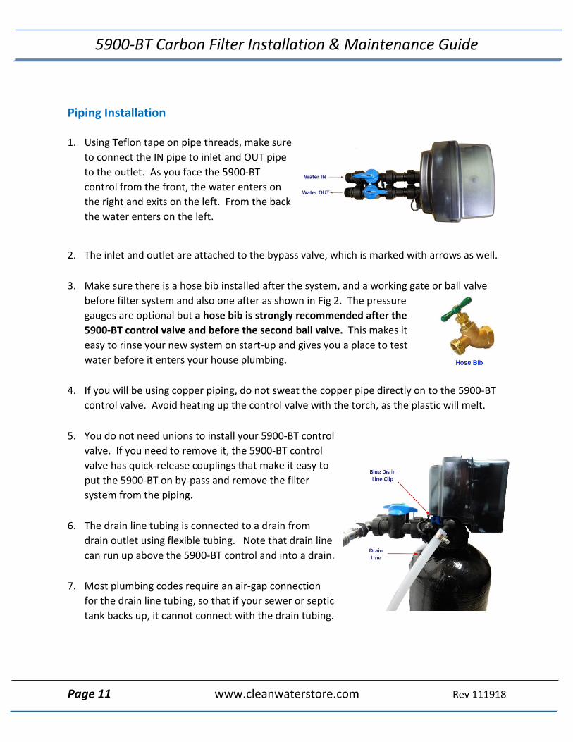
Piping Installation
1. Using Teflon tape on pipe threads, make sure to connect the IN pipe to inlet and OUT pipe to the outlet. As you face the 5900-BT control from the front, the water enters on the right and exits on the left. From the back the water enters on the left.
2. The inlet and outlet are attached to the bypass valve, which is marked with arrows as well.
3. Make sure there is a hose bib installed after the system, and a working gate or ball valve before filter system and also one after as shown in Fig 2. The pressure gauges are optional but a hose bib is strongly recommended after the 5900-BT control valve and before the second ball valve. This makes it easy to rinse your new system on start-up and gives you a place to test water before it enters your house plumbing.
4. If you will be using copper piping, do not sweat the copper pipe directly on to the 5900-BT
control valve. Avoid heating up the control valve with the torch, as the plastic will melt.
5. You do not need unions to install your 5900-BT control valve. If you need to remove it, the 5900-BT control valve has quick-release couplings that make it easy to put the 5900-BT on by-pass and remove the filter system from the piping.
6. The drain line tubing is connected to a drain from
drain outlet using flexible tubing. Note that drain line can run up above the 5900-BT control and into a drain.
7. Most plumbing codes require an air-gap connection
for the drain line tubing, so that if your sewer or septic tank backs up, it cannot connect with the drain tubing.
5900-BT Carbon Filter Installation & Maintenance Guide
Page 12 www.cleanwaterstore.com Rev 111918
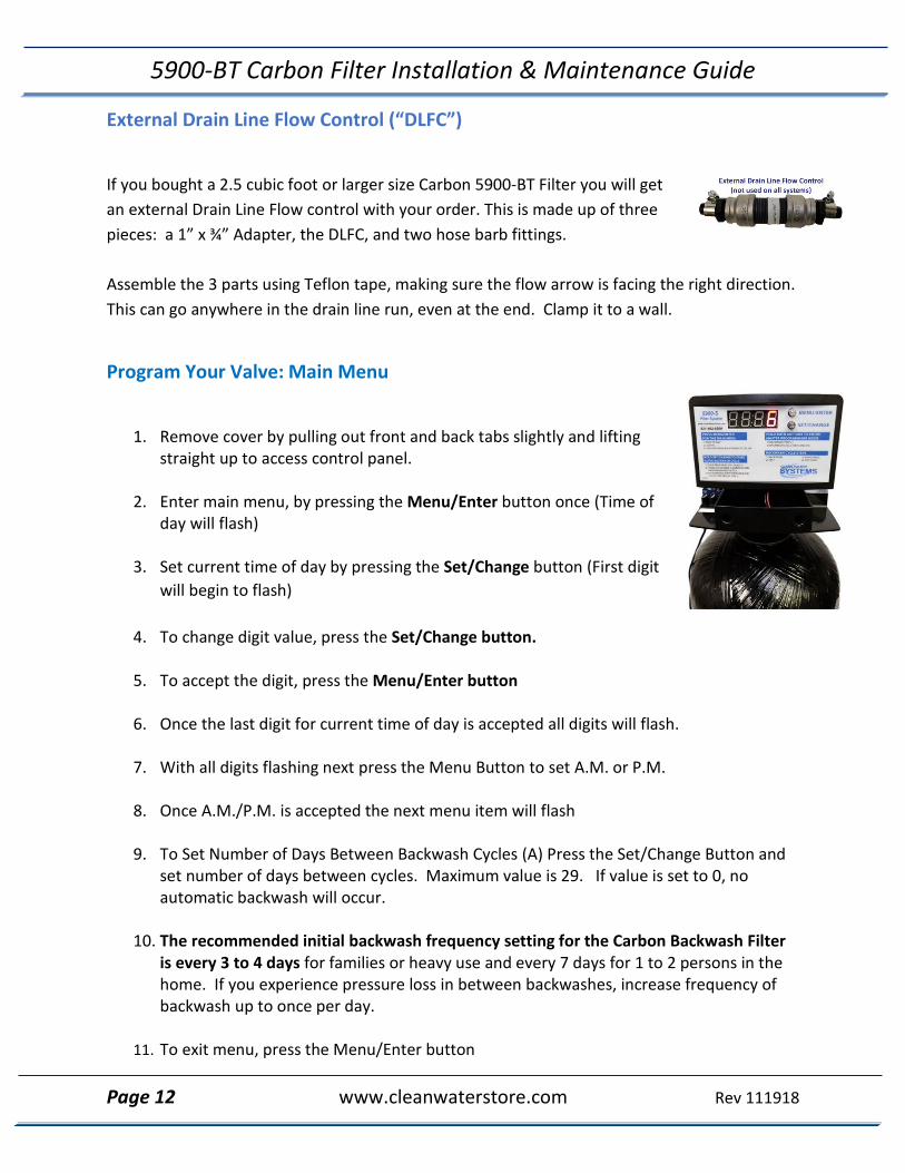
External Drain Line Flow Control (“DLFC”)
If you bought a 2.5 cubic foot or larger size Carbon 5900-BT Filter you will get an external Drain Line Flow control with your order. This is made up of three pieces: a 1” x ¾” Adapter, the DLFC, and two hose barb fittings.
Assemble the 3 parts using Teflon tape, making sure the flow arrow is facing the right direction. This can go anywhere in the drain line run, even at the end. Clamp it to a wall.
Program Your Valve: Main Menu
1. Remove cover by pulling out front and back tabs slightly and lifting straight up to access control panel.
2. Enter main menu, by pressing the Menu/Enter button once (Time of day will flash)
3. Set current time of day by pressing the Set/Change button (First digit will begin to flash)
4. To change digit value, press the Set/Change button.
5. To accept the digit, press the Menu/Enter button
6. Once the last digit for current time of day is accepted all digits will flash.
7. With all digits flashing next press the Menu Button to set A.M. or P.M.
8. Once A.M./P.M. is accepted the next menu item will flash
9. To Set Number of Days Between Backwash Cycles (A) Press the Set/Change Button and set number of days between cycles. Maximum value is 29. If value is set to 0, no automatic backwash will occur.
10. The recommended initial backwash frequency setting for the Carbon Backwash Filter is every 3 to 4 days for families or heavy use and every 7 days for 1 to 2 persons in the home. If you experience pressure loss in between backwashes, increase frequency of backwash up to once per day.
11. To exit menu, press the Menu/Enter button

5900-BT Carbon Filter Installation & Maintenance Guide
Page 13 www.cleanwaterstore.com Rev 111918
Program Your Valve: Master Programming Mode
1. Regeneration Time (r) Press the Menu/Enter Button. To enter Master Programming Mode press and hold both buttons for 5 seconds. The next display viewed is the option setting for Regeneration Time. It is identified by the letter ‘r’ in the left digit. Set the desired time of day that a regeneration may occur, when required. We recommend setting the system to backwash at 2 AM, or at any time that it is unlikely that any water will be used. If you have 2 or more filters, make sure they are programmed to start an hour apart, so they do not backwash at the same time. The first digit(s) indicates the Hour and the other digit indicates A.M. or P.M. Example: 12 A.M. regeneration time - [ r 12A ] (factory setting) 2. Regeneration Cycle Step Programming Times The next 3 displays viewed are part of a series of option settings used to program the Regeneration Cycle which is where the filter backwashes and rinses itself. Up to 3 steps can be programmed and they are: Backwash, Rest, and Rapid Rinse. Each display is used to set the duration time in minutes for that specific step in a regeneration cycle. Regeneration steps are skipped by setting the display to 0 as shown below: Set each step according to the values below, appropriate for a 5900-BT filter system: 1 10 minutes. This is the BACKWASH cycle. [ 1 - 10] (Set for 6 minutes minimum) 2 5 minutes. This is the REST cycle. [ 2 - 5] 3 6 minutes. This is the RAPID RINSE cycle. [ 3 - 05] (Set for 4 minutes minimum) 4 Next step will be “bE 1”. If you are using the Bluetooth Legacy App, the 01 means that it’s ready. 5 Next and final step is bbPP is displayed for one second, then password is displayed.
Press the menu/enter button, and now you are back to the home service screen (displaying the clock time and the number of days until backwash). bE is for Bluetooth enabled.
5900-BT Carbon Filter Installation & Maintenance Guide
Page 14 www.cleanwaterstore.com Rev 111918
See Historical Data and Real Time Flow Rate Pressing and holding the Menu/Enter button will also access some options: Flo- this is the flow rate, if water is running, it will display the volume, in gallons per minute. Gt r- This the total # of gallons that has gone through the filter. g tot- this is the same as the previous. rC r- number of regeneration done. rC- the same. gPdL- shows how many gallons used each day. Gbrl- is the gallons used between regenerations. PfDL- This shows the peak, or highest flow rate that has passed through the filter in the last 24 hours. If you “get stuck” in these options, keep pressing the Menu/Enter button until you have returned to the service screen.
Detailed Steps to Starting Up Carbon Backwash Filter System
1. Carbon filter media has a lot of black fines or dust, and must be rinsed free by backwashing and rinse, which may take several backwashes.
2. MAKE SURE THE SOUCE WATER ENTERS THE INLET PIPING (IN OTHER WORDS, THAT THE SYSTEM IS PIPED IN CORRECTLY, WITH THE WATER INLET TO THE INLET ON THE BYPASS VALVE)
3. MAKE SURE THAT BOTH THE INLET AND OUTLET BYPASS VALVES ARE CLOSED INITIALLY
4. MAKE SURE TO CLOSE BALL VALVE OR GATE VALVE AFTER FILTER SO NO WATER CAN ENTER HOME DURING INITIAL BACKWASH. (If you did not install a hose bib and gate or ball valve after the system as recommended, be sure to NOT use any water in the home during the initial start-up.)
5. If you have any filters or softeners installed after the filter system, bypass them until all media fines have been rinsed.
6. First, if days remaining is not already at 1, press and hold the Set/Change button.
7. Next press and hold the Set/Change button, until the valve begins the backwash cycle and the display reads 1 [1- 10]. This is the first cycle that starts a backwash.

5900-BT Carbon Filter Installation & Maintenance Guide
Page 15 www.cleanwaterstore.com Rev 111918
8. Start to put the valve into the service position by turning the inlet bypass knob counter-clockwise about a quarter inch, until you can hear water passing through the bypass into the filter. Stop and wait until you see water coming out of the drain line. It will often be mixed with air bubbles.
9. When you do not see bubbles anymore, keep opening the valve, a little bit at a time, stopping for a minute or two each time. You want to see a corresponding increase in flow out of the drain line as you increase the flow of water into the filter. \
10. After several minutes, you should have the valve fully open, and with no media coming out. The water will be black, turning to gray, mostly clear water- the water does not get crystal clear in the Backwash mode (only at the end of Rapid Rinse and during Service).
11. After the backwash cycle, the filter will go into a rest for 5 minutes. After 5 minutes the next cycle, the Rinse cycle will start.
12. NOTE: To skip to the next cycle or fast forward past Rest or other cycles, hold down Set/Change button for 3 seconds.
13. Let the unit do the Rapid Rinse cycle and advance to the “Service” position.
14. Repeat Step 1 and start up another backwash, rest, rinse sequence. You may need to backwash the filter 2 or 3 times to thoroughly clean up the filter media.
15. Next, open the outlet on the bypass valve and then open the hose bib after the system and allow the water to run until it is clear. Run water in the home using a bathtub, laundry sink, or other fixture that does not have an aerator screen as any remaining residue may get caught in the screen. Run the water in the home for 5 to 10 minutes to flush pipes.
Congratulations, you are done starting up your filter system!

5900-BT Carbon Filter Installation & Maintenance Guide
Page 16 www.cleanwaterstore.com Rev 111918
Installing and Using the Optional Legacy View App
For simplified set up and control, please install the Legacy View on a compatible Bluetooth 4.0+ enabled smart phone or tablet. 1. Download and install the Legacy View app from the Google Play Store, Apple App Store.
2. Open the Legacy View app 3. Choose a valve device at any time from the list of available devices to connect to by clicking
on it (which means your 5900-BT control valve, or valves if you have more than one system)
4. If the valve you want to connect to doesn’t show up, or there is a problem connecting press the “Scan for Devices” button or the Legacy View logo at any time to refresh the list and start the process over.
5. If the valve device is a BTLE valve and it has a password other than the default password, the first time you connect to it the app will ask you to enter the password.
6. After entering it the first time you should not need to enter it again unless it changes.
7. The control valve firmware can be updated by the App. When the app is updated from the Google Play Store or the Apple App Store, it may contain an updated firmware program for the valve devices.
8. These updates could contain new features or operational improvements. It is up to the user to allow these updates to be sent to the valve device. Uploading a new program takes approximately 1 minute.

5900-BT Carbon Filter Installation & Maintenance Guide
Page 17 www.cleanwaterstore.com Rev 111918
Legacy Phone App Dashboard
From the Dashboard, all items in ORANGE can be changed, while blue fields are informational only. If you are unsure about the function of the field, click the Info icon for more information
1. Change Time of day (Press “set” to set time automatically based on device time)
2. Set Backwash Frequency. This sets the amount of days between backwash cycles.

5900-BT Carbon Filter Installation & Maintenance Guide
Page 18 www.cleanwaterstore.com Rev 111918
3. Set Regeneration Time. Example: For 2am, just type 2 and press OK.
Legacy App Advanced Settings
From the Advanced Settings, all items in ORANGE with a “set” button can be changed.
Touch any table to explode a detailed list of the last 60 days.

5900-BT Carbon Filter Installation & Maintenance Guide
Page 19 www.cleanwaterstore.com Rev 111918
Status and History Using Legacy View App
From the Status and History, all items in ORANGE can be reset.
Start a regeneration or backwash cycle
Option 1: Click on “Regenerate Unit Now.”
If you would like to force the unit into the next cycle step, Click “Go to next Regeneration Step.”
Option 2: “Regenerate Unit at next Regen Time” button. This will take the system into a backwash at the next regeneration time.

5900-BT Carbon Filter Installation & Maintenance Guide
Page 20 www.cleanwaterstore.com Rev 111918
Filter System Normal Operation
• Normal display alternates between time of day and days until regeneration.
• Days remaining until the next regeneration will count down from the regeneration day override value to 1 day remaining.
• Once count reaches 1, a regeneration will be initiated at next scheduled regen time.
How to Start A Manual Backwash
1. If days remaining is not already at 1 press and hold the Set/Change button.
2. After 7 seconds the days remaining display will read: [1]
3. With days remaining at 1 press and hold the Set/Change button again.
4. After 5 seconds the regeneration cycle will begin.
5. Fast Cycling Through each Step
6. First complete above immediate cycle steps
7. Press and hold the Set/Change button
8. After 3 seconds the valve will start to advance to the next step
5900-BT Carbon Filter Installation & Maintenance Guide
Page 21 www.cleanwaterstore.com Rev 111918
Carbon Backwash Filter Maintenance
No weekly or monthly maintenance is required. If your water is extremely high in hardness, sediment or grit, you may need to replace the piston, seals and spacers every 1 to 5 years.
The Carbon filter media typically lasts 4 to 6 years. You can test for chlorine residual before and after Carbon Backwash Filter. If you detect a chlorine residual after filter, it is likely time to replace the carbon media soon.
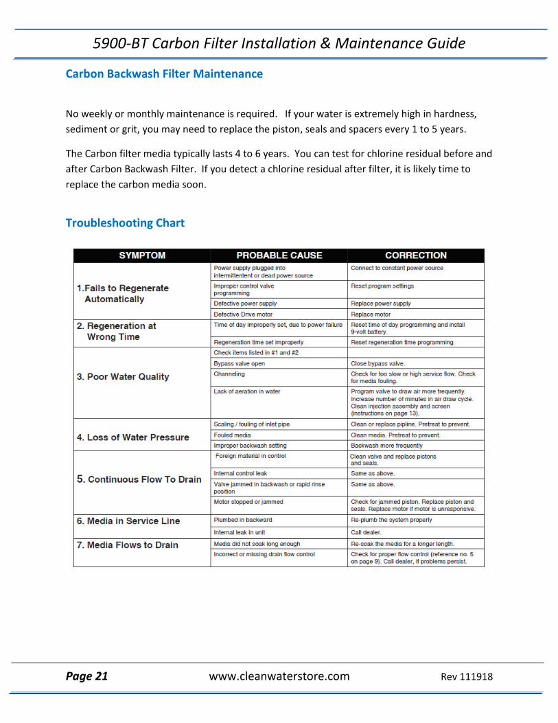
Troubleshooting Chart

5900-BT Carbon Filter Installation & Maintenance Guide
Page 22 www.cleanwaterstore.com Rev 111918
Error Codes There are five (5) error codes that could indicate a possible problem with the control valve: Error 2 - Homing slot expected. Valve will start looking for home. (Normal operation continues) Error 3 - Encoder is not sending a signal (Either encoder chip has failed, or is not connected) Error 4 - Unable to find homing slot (Usually because encoder chip has failed) Error 5 - Motor overload (stalled position or shorted motor, valve requires service to continue) Error 6 – Motor not getting power (usually means cable has disconnected from circuit board.)
Pressure Loss from Inadequate Backwash Flow Rate One problem that may occur is if you do not have enough backwash flow rate to properly clean the Carbon filter media, particularly if you are on well water and have very low flow and pressure (not usual). “Flow Rate” is simply how many gallons will flow in one minute, out the drain tubing. If the system is in a backwash and flowing, if it fills a 5-gallon bucket in one minute, it is “5 GPM” You can verify the backwash flow rate by running the drain line into a bucket and timing it when the 5900-BT control is in backwash.

5900-BT Carbon Filter Installation & Maintenance Guide
Page 23 www.cleanwaterstore.com Rev 111918
Problems with Pressure Loss or Reduced Flow 1. First make sure that the problem is the 5900-BT Filter and not another cause. Check the
flow rate out of a faucet, with the 5900-BT control valve on by-pass. 2. Greater flow and pressure when the unit is on bypass means the problem is in the filter. No
change would indicate the problem is before the filter. 3. The valve: Over time, deposits can build up on the inside of the valve, and prevent the
piston from moving, or fully advancing to where it needs to be, and this can affect the flow. The solution is to replace the seals and spacers, clean the valve where you removed the parts, clean and inspect the piston, and re-install.
4. The filter media: As is already noted in the guide, backwash must be done with sufficient
flow rate and be backwashed frequently enough to keep the filter media clean. 5. Mud-ball formation: If your water has high levels of sediment, silts, or clay getting into the
filter, over time these elements combine to form balls which will ruin filter performance. If multiple backwashes do not recover the media, take the control head off & inspect media.
Service Instructions – Perform Before Doing Any Service A1. Turn off water supply to filter and put it in the bypass position. A2. Remove cover and relieve water pressure in the 5900-BT control valve by stepping the control into the backwash position momentarily. Return the control to the service position. A3. Unplug electrical cord from outlet.
How to Replace Powerhead B1. Remove the control valve cover and disconnect the power supply. B2. Disconnect meter cable from circuit board, feed through control (if meter is being re-used) B3. Remove lower back base screws and detach lower back base. B4. Remove screw and washer at drive yoke.
5900-BT Carbon Filter Installation & Maintenance Guide
Page 24 www.cleanwaterstore.com Rev 111918
B5. Remove powerhead mounting screws. B6. The entire powerhead assembly will now lift off easily. B7. Put new powerhead on top of the valve. Be sure the drive pin on main gear engages slot in drive yoke (wide side of drive yoke upright must face to the left away from the motor). B8. Replace powerhead mounting screws. Replace screw and washer at drive yoke. B9. Reattach lower back base. B10. Reconnect meter signal, wire and power supply.
B11. Reinstall cover.
How to Replace Piston Assembly C1. Follow steps A1 - A3 C2. Disconnect the meter signal wire from the circuit board. C3. Remove lower back base screws and detach lower back base. C4. Remove screw and washer at piston drive yoke. Remove powerhead mounting screws. The entire powerhead assembly will now lift off easily. C5. Remove piston retaining plate screws. C6. Pull upward on end of piston yoke until assembly is out of valve. C7. Inspect the inside of the valve to make sure that there is no foreign matter that would interfere with the valve operation. C8. Install new seals and spacers. C9. Take new piston assembly and push piston into valve by means of the end plug. C10. Twist drive yoke carefully in a clockwise direction to properly align it with drive gear. C11. Reinstall piston retaining plate screws. C12. Follow steps B5 - B9

5900-BT Carbon Filter Installation & Maintenance Guide
Page 25 www.cleanwaterstore.com Rev 111918
How to Replace Seals and Spacers D1. Follow steps A1 - A3. D2. Disconnect the meter signal wire from the circuit board. D3. Remove screw and washer at piston drive yoke. Remove powerhead mounting screws. The entire powerhead assembly will now lift off easily. Remove piston retaining plate screws. D4. Pull upward on end of piston rod yoke until assembly is out of valve. Remove seals and spacers. (Note: Special end spacer must be reused) D5. Lubricate new seals with silicone lubricant included in the seal and spacer kit. Make sure the special end spacer is properly seated in the valve body. Install new seals and spacers individually, pressing around the outer edge of each seal to make sure it is seated. (When all seals and spacers are seated properly, you will have a 1/4” of space between the top seal the top of the valve body) D6. Follow Steps C9 to C10.
How to Replace Meter E1. Follow steps A1 - A3 E2. Unplug meter cable from front of circuit board. E3. Unscrew meter assembly nut from valve body. E4. Remove meter from valve body and clean or replace as necessary. E5. Reinstall meter, nut and cable.

5900-BT Carbon Filter Installation & Maintenance Guide
Page 26 www.cleanwaterstore.com Rev 111918
How to Replace the Carbon Filter Media
1. Typically, after 3 to 6 years the Carbon Media will stop removing chlorine and needs to be replaced. To accomplish this:
2. Turn water to system and depressurize the filter by opening a hose bib or faucet after the Sediment backwash filter system.
3. Put system on bypass and remove the union fittings between the bypass valve and the 5900-BT control valve.
4. Unscrew the control valve and set aside.
5. Siphon water out of the carbon backwash filter by inserting a small flexible tube down the distributor tube and siphoning out the water.
6. Lay down a clean tarp outside or somewhere you can flush water and clean the tank out.
7. Insert a garden hose in the tank and allow water to flow down center distributor tube. Carbon Media will begin to flow out on to the tarp.
8. Flush out all Carbon Media and gravel and discard to landfill or trash. Observe all local laws and codes, generally it is acceptable to dispose of the media in a landfill.
9. Rinse out filter tank until clean.
10. Add a ½ cup of unscented household bleach and a few gallons of water and rinse inside of tank with chlorinated solution.
11. Rinse out filter tank until chlorine is gone.
12. Add gravel and new Carbon media and re-start up system following original directions in this manual.

5900-BT Carbon Filter Installation & Maintenance Guide
Page 27 www.cleanwaterstore.com Rev 111918
Valve Body Assembly S900-BT

5900-BT Carbon Filter Installation & Maintenance Guide
Page 28 www.cleanwaterstore.com Rev 111918
Control Valve Assembly 5900-BT

5900-BT Carbon Filter Installation & Maintenance Guide
Page 29 www.cleanwaterstore.com Rev 111918
Water Filters Limited Warranty
We warrant this water filter/ softener/ conditioner, when installed according to factory recommendations, to be free from defects in materials and workmanship as follows:
----------Limited Warranty----------
This water conditioner unit is comprised of the finest industry components available. Each individual component used in the assembly of our equipment is covered by the original equipment manufacturer’s warranty. All components, except those specifically listed below, are warranted for a period of one (1) year from date of installation to the original purchaser to be free of defects in materials and workmanship subject to the manufacturer’s conditions and/or the conditions shown below.
----------Mineral Tanks----------
The fiberglass, polyglass or composite mineral tanks used in the assembly of this unit are warranted to be free of defects in materials and workmanship for a period of ten (10) years on 6” – 13” size tanks, and five (5) years on 14” and larger size tanks used for softener/filtration applications, subject to the manufacture’s conditions and/or the conditions shown below. Warranty does not cover exposure to weather, freezing, fractures caused by external impact, or exposure to vacuum.
----------Control Valves----------
The CWS control valve is warranted to be free of defects in materials and workmanship for a period or seven (7) years, subject to the manufacturer’s conditions and/or the conditions shown below. Fleck & other brand control valves have 5-year warranty.
----------Conditions----------
1. This warranty only covers water conditioners installed for residential use. Water conditioners installed for commercial or industrial applications are guaranteed for one (1) year from the date of installation.
2. Installation must be made in accordance with legal or local codes and manufacturer’s recommendations.
3. Failure must not result from exposure to weather, rodents, misuse, alteration, fire, lightning, power surges or neglect.
4. Water pressure must not exceed 100 PSI and water temperature must not exceed 100 degrees.
5. Subject to the above terms and conditions we will replace and/or repair, at our option, any parts of the water conditioner found defective in materials and workmanship. Defective parts must be returned, freight pre-paid for repair or replacement.
6. This warranty does not cover labor, shipping charges, damages caused by delays of consequential damages or other causes beyond our control. Warranty does not cover pipes, fixtures or appliances. Warranty extends to the actual water conditioner components only.
7. This warranty is to the original purchaser and is not transferable after the third year to any subsequent owner(s).
8. No other guarantees or warranty, expressed or implied, is applicable to our product. No repair or replacement made under the terms of the warranty shall extend this warranty.