5995420543 frigidaire 5.75 cuft gas electric dryer good and better models
DESCRIPTION
5995420543 Frigidaire 5.75 cuft Gas Electric Dryer Good and Better Models.TRANSCRIPT

1
5995420543 January 2005
White-Westinghouse
ELECTROLUX HOME PRODUCTS NORTH AMERICA
SERVICE MANUAL
5.75 Cu. Ft. Dryer
Gas & Electric
Good and Better
Models

2
ATTENTION!!!This service manual is intended for use by persons having electrical and mechanicaltraining and a level of knowledge of these subjects generally considered acceptable inthe appliance repair trade. Electrolux Home Products cannot be responsible, nor assumeany liability, for injury or damage of any kind arising from the use of this manual.
© 2005 Electrolux Home Products, Inc.
SAFE SERVICING PRACTICES - ALL APPLIANCES
To avoid personal injury and/or property damage, it is important that SafeServicing Practices be observed. The following are some limited examples ofsafe practices:
1. DO NOT attempt a product repair if you have any doubts as to your ability tocomplete it in a safe and satisfactory manner.
2. Before servicing or moving an appliance:• Remove the power cord from the electrical outlet, trip the circuit breaker to
the OFF position, or remove the fuse.• Turn off the gas supply.• Turn off the water supply.
3. Never interfere with the proper operation of any safety device.
4. USE ONLY REPLACEMENT PARTS CATALOGED FOR THIS APPLIANCE.SUBSTITUTIONS MAY DEFEAT COMPLIANCE WITH SAFETYSTANDARDS SET FOR HOME APPLIANCES.
5. GROUNDING: The standard color coding for safety ground wires is GREEN,or GREEN with YELLOW STRIPES. Ground leads are not to be used as currentcarrying conductors. It is EXTREMELY important that the service technicianreestablish all safety grounds prior to completion of service. Failure to do sowill create a hazard.
6. Prior to returning the product to service, ensure that:• All electrical connections are correct and secure• All electrical leads are properly dressed and secured away from sharp
edges, high-temperature components, and moving parts• All non-insulated electrical terminals, connectors, heaters, etc. are
adequately spaced away from all metal parts and panels• All safety grounds (both internal and external) are correctly and securely
connected• All panels are properly and securely reassembled

3
SAFE SERVICING PRACTICES 2QUICK REFERENCE SHEET 7
Serial nameplate location 7Serial number breakdown 7Tech sheet location 7Function test sequence 8Specification 9Component resistance chart 10Sample wiring diagram for electric models 11Sample wiring diagram for gas models 12
SECTION A - OPERATING INSTRUCTIONS 13Before operating your dryer 13Operating steps 13Cycle Selection 13
Auto Dry 13Towels 13Normal 14Perm Press 14Delicates 14Quick 14Touch Up 14
Temperature Selection 14Cycle Adjustment 14Dryness Level 14Cycle Options 14
Cycle Signal 14Press Saver 14
Dryer Features 15Control Lock 15Status Lights 15
Dryer Setting Chart 16SECTION B - OWNERS GUIDE 17
Safety information 17What to do if you smell gas 17Your Safety and the Safety of other is very Important 17Pedestal 17Important safety instructions 17Prevent fire 17Protect children 18Prevent injury 18
Drying Procedures 19Features 20
End of cycle signal 20Drum light 20Reversible dryer door 20Drying rack 20
Common drying problems 21Care and cleaning 22
Inside 22Outside 22
Avoid service checklist 23Sample Warranty 25
SECTION C - INSTALLATION INSTRUCTIONS GAS & ELECTRIC DRYER 26What to do if you smell Gas 26Pre-installation requirements 27
4
Tools and materials required for installation 27Electrical requirements 27
Electric dryers 27Gas dryers 27
Exhaust system requirements 27Exhaust directions 29Exhaust duct locating dimensions 29Gas supply requirements 29Location of your dryer 29
Do not install your dryer 29Installation in a recess or closet 29
Minimum installation clearances 29This dryer must be exhausted outdoors 29Rough-in dimensions 30Mobile home installation 32Unpacking 32Reversing door swing 32Solid door reversal instructions 32Window door reversal instructions 33Electrical installation 35
Electric dryers 35Grounding requirements 35
For a grounded, cord-connected dryer 35For a permanently connected dryer 35
Gas dryer 35Electrical connections for 3-wire system 36Electrical connections for 4-wire system 36Gas connection 36General installation 37Replacement parts 37
SECTION D - Pedestal Installation Instructions 38Washer Installation 38Dryer Installation 40Warranty 42
SECTION E - HOW THE COMPONENTS WORK 43The basic components 43
Drum 43Heat source 43
Electric 43Gas 43
Drive motor and blower 43Control thermistor 44Electronic control board 44
Airflow 44Airflow electric dryers 44Airflow gas dryers 44
Airflow problems 45Restrictions 46Air leaks 46Short unrestricted vents 46
Electrical operation (Electric dryers models) 46Electronic control board circuits 46Drive motor circuit 47Temperature sensing circuit 47The heating circuit 47Drying time 48

5
Electrical Operation (Gas Dryers Models) 48Electronic control board circuits 48Drive motor circuit 48Temperature sensing circuit 49The heating circuit 49Drying time 50
SECTION F - TROUBLESHOOTING 51Error codes 51Error code chart 52Troubleshooting flow charts index 53
Electric dryer completely inoperative 54Gas dryer completely inoperative 55Electric and gas dryers; blower motor runs but drum does not turn 56Electric and gas dryers; longer than normal drying times 56Electric dryer not heating properly 57Gas dryer not heating properly 58Electric and gas dryers; dryer over heating 58Electric dryers; blower motor runs but dryer does not heat 59Gas dryers; blower motor runs but dryer does not heat 60Electric and Gas dryers; clothes not dry in auto cycle 61
SECTION G - TEARDOWN 62Removing the top panel 62Removing the temp knob 62Removing the console 62Removing the control board 63Removing the programing buttons and springs 63Removing the temp knob shaft 63Removing the selector knob shaft 64Removing the selector knob 64Removing the loading door 64Disassembling the loading door 64Removing the door handle 65Removing the upper or lower door strike 65Removing the door seal 65Removing the front access panel 65Removing the door switch 65Removing the front panel 66Replacing the sensor bars 67Replacing the front panel air duct 67Replacing the upper door catch 67Replacing the lower door catch 67Replacing the drum light bulb 68Replacing the drum light housing 68Replacing the drum light socket 68Replacing the felt seal 68Replacing the foam seal 69Removing the rear vent 69Releasing the dryer belt 69Removing the vane from the drum 69Removing the drum 69Removing the belt 70Removing the hitch ball from the drum 70Removing the teflon glides 70Removing the drum heat shield (Electric dryers) 71Removing the hitch 71

6
Removing the high limit thermostat 71Removing the thermal limiter (Electric dryers) 71Removing the heating element assembly (Electric dryers) 72Removing the control thermistor 72Removing the blower housing and fan blade 72Removing the idler pulley 73Removing the idler pulley assembly 73Removing the drive motor 73Removing the burner (Gas dryers) 74Removing the ignitor (Gas dryers) 74Removing the gas valve assembly (Gas dryers) 74Removing the gas valve coils (Gas dryers) 75Removing the sensor (Gas dryers) 75Removing the combustion chamber (Gas dryers) 75Removing the duct and heat shield (Gas dryers) 76Removing the manifold pipe (Gas dryers) 76Removing the vent pipe (Gas dryers) 77Removing the gasket between the vent pipe and blower housing 77

7
QUICK REFERENCE SHEET
1. Serial nameplate location: on the frontpanel at the left side of the dryer dooropening.
2. Serial number breakdown.
3. Tech sheet location
Front console models: on the right-handbodyside behind the front paneland inside rear access panel.
X D 5 0 4 0 4 2 4 7
Incremented unit numberProduction week
Last digit of production yearProduct identification
Manufacturing Facility

8
Function test sequence
This is a functional test for the dryer. To activate thismode, perform the following steps:
1. Digital Display Models: Turn the cycle selector knobto the Normal position.Non-Digital Display Models: Turn the cycle selectorknob to the 12 O’clock position.
2. Press and hold the Select and Pause Cancel buttonssimultaneously for (6) seconds.
3. Immediately after, press and hold the Pause Canceland START buttons for (4) seconds.
The control will enter the test mode, the buzzer will sound3 times and all LED’s will rapidly flash.
After entering the test mode, the selector know can nowbe rotated to select the following test.
Rotate program knob clockwise from the start position:
1 Turn Drive motor runs, heat source is on.Drying LED is lit. “H” and the controlthermistor reading will toggle back andforth in the display. **
2 Turns Drive motor runs; heat source is off. CoolDown LED is lit and “AF” (Air Fluff) isdisplayed.
3 Turns Drive motor runs; heat source is off.Drying and Cool Down LED’s are lit andnumbers appear in the display showingmoisture sensor readings. Opening thedoor (press in on door switch plunger) andplacing a finger on the both moisturesense bars at the same time will makethe numbers decrease. In controls thatdo not have a digital display, the MOREDRY LED should be ON. Opening the door(press in on door switch plunger) andplacing a finger on both moisturesense bars at the same time will makethe DAMP LED come on.
4 Turns Drive motor runs; heat source is off.Key test:a. When the Temp key is pressed, all
the Temp LEDs should light. If theTemp selector is the rotary knob, andthe knob is rotated, there should bea key beep with each setting.
QUICK REFERENCE SHEET
b. When the DRYNESS key is pressed,all the dryness level LEDs shouldlight.
c. When the OPTIONS or Select keyis pressed, all the options LEDSshould light.
d. When the START key is pressed, allthe cycle status LEDs should light.
e. When the Pause Cancel key ispressed, all the cycle status LEDsshould light.
5 Turns Drive motor runs; heat source is off. CoolDown LED is lit. Control thermistor reading is displayed.**
6 Turns Drive motor runs; heat source is on.Drying LED is lit. Control thermistorreading is displayed.**
**For models that do not have a digital display, thedryness LED’s are used to determine the controlthermistor reading. The number of flashes of the bottomthree LEDs will determine the value of the temperatureas follows.
NORMAL = HUNDRED’SLESS DRY = TEN’SDAMP = ONE’S
Example: Normal flashes 1 timeLess Dry flashes 2 timesDamp flashes 6 timesTemperature = 126 degrees.
To EXIT test mode, press and hold the Select and PauseCancel buttons simultaneously for six seconds ordisconnect power from dryer. Dryer will be reset for regularoperation.

9
QUICK REFERENCE SHEET
SPECIFICATION
ElectricalVolts 120/208 or 120/240Amps (circuit)Motor wattageHeat input (Watts @ 240 VAC)Heat input (BTU/Hr.)Auto. Elec. Ignition
DrumSize (Cu. Ft.)FinishR.P.M.
Airflow CFM
DRUM TEMPERATURES (Max.opening on 1st cycle)HighMediumMedium/LowLow
Dimension (Inches)Height (Stack Models)WidthDepth
Vent Capability**
Top Finish
Port Opening (Sq. In.)
ELECTRIC MODELS
120/208 or 120/24030
160-350 Watts3200/4500
------
5.7Power Paint Epoxy
48 - 54
200
138° - 190°134° - 180°130° - 170° 120° - 165°
36”27”
28.5”
4-Way
Power Paint Enamel
235
± ± ±
±±
GAS MODELS
12015
160-350 Watts---
20,000Yes
5.7Power Paint Epoxy
48 - 54
200
145° - 190°140° - 180°130° - 170° 120° - 165°
36”27”
28.5”
3-Way
Power Paint Enamel
235
** Electric dryers can be vented four ways: through back, bottom, right or left side.** Gas dryers can be vented three ways: through back, bottom, or right side.

10
QUICK REFERENCE SHEET
Component Resistances*
Drive motor (120 volt, 60 Hz, 1/4 h.p. 1725 rpm)Motor Start WindingMotor Run Winding
Heating Element
Control Thermistor
Burner AssemblyIgnitorSecondary CoilBooster Coil
Electric Models
4.5 Ohms3.8 Ohms
12.8 Ohms
50,000 Ohms
---------
Gas Models
4.5 Ohms3.8 Ohms
50,000 Ohms
50 - 400 Ohms1200 Ohms1320 Ohms
* +/- 10% @ 77° F

11
SAMPLE WIRING DIAGRAM FOR ELECTRIC MODELSCAUTION: DISCONNECT ELECTRIC CURRENT BEFORE SERVICING. LABEL ALL WIRES PRIOR TODISCONNECTION WHEN SERVICING CONTROLS. WIRING ERRORS CAN CAUSE IMPROPER AND
DANGEROUS OPERATION. VERIFY PROPER OPERATION AFTER SERVICING.

12
SAMPLE WIRING DIAGRAM FOR GAS MODELS
CAUTION: DISCONNECT ELECTRIC CURRENT BEFORE SERVICING. LABEL ALL WIRES PRIOR TODISCONNECTION WHEN SERVICING CONTROLS. WIRING ERRORS CAN CAUSE IMPROPER AND
DANGEROUS OPERATION. VERIFY PROPER OPERATION AFTER SERVICING.

13
7. Press START to begin cycle.
• To pause the cycle or change settings, pressPAUSE/CANCEL once.To resume the cycle,press START again.
• To stop or change the cycle, press PAUSE/CANCEL twice.
8. A signal will sound at the end of the cycle andperiodically during Press Saver when the CycleSignal option is selected. When the cycle ends,remove items immediately and hang or fold.
9. Clean the lint screen after every load.
Cycle Selection
For best results, follow the fabric care label instructionson items to be dried.
Auto Dry
Auto Dry cycles take the guesswork out of drying time.The load will automatically be dried at the selected tem-perature to the desired dryness level. The dryer sensesthe moisture level of the load as it tumbles through heatedair. Auto Dry cycles save time and energy and protectfabrics.
When the load has reached the selected dryness level,it will continue to tumble, unheated, during a Cool Downperiod. This helps reduce wrinkling and makes itemseasier to handle during unloading.
Drying time varies depending on size and dampness ofload and fabric type. Room temperature and humidity,type of installation and electrical voltage or gas pressurecan also affect drying time.
Towels
Select this Auto Dry cycle for towel loads.
SECTION A - OPERATING INSTRUCTIONS
Before Operating Your Dryer
Read your dryer Use and Care Guide. It has impor-tant safety and warranty information. It also has manysuggestions for best drying results.
To reduce the risk of fire, electric shockor injury to persons, read the IMPORTANT SAFETY IN-STRUCTIONS in your dryer Use and Care Guide beforeoperating this appliance.
Operating Steps
Read “Drying Procedures” in your Use and Care Guide.It explains these operating steps in detail.
1. Prepare items for drying.
2. Check that lint screen is clean and in place.
3. Load the dryer. If desired, add a dryer fabric softenersheet. Close the door.
4. Select the cycle and drying temperature for each load.To change the temperature, turn the TEMP knob tothe desired temperature.
5. A suitable dryness level and options willautomatically be displayed for each cycle. Tochange the dryness level, press DRYNESS untilthe desired selection is made. To select an option,press OPTIONS until the indicator for a desiredoption flashes and press SELECT. Follow thesame steps to delete an option. If a dryness level oroption is not available for a cycle,it will not light.
6. The changes you make will be remembered thenext time that cycle is selected. See the “DryerSettings Chart” for more details.
AUTO DRY
Control
TIMED DRY
15
30
45 60
75
90
Towels
Normal Perm Press
Dellcate
Quick
Touch Up
High
Med
Low
NoHeat
TEMP
Normal More Dry
Less Dry Damp
DRYNESS
Press Saver Cycle Signal
OPTIONS SELECT START
Press Saver
PauseControl
Drying Cool Down
Clean Lint Filter

14
Normal
Select this Auto Dry cycle for cotton items.
Perm Press
Select this Auto Dry cycle to dry cotton items and blendswith a no-iron finsh.
Delicates
Select this Auto Dry cycle for knit and delicate items.
Quick
Select this Auto Dry cycle to quickly dry a small loadmade up of just a few items.
Touch Up
Select Touch Up to help remove wrinkles from clean anddry items that were not taken from the dryer at the end ofthe cycle, have been stored in crowded closets ordrawers, or unpacked from luggage following a trip. Itprovides approximately 10 minutes of low heat tumblingfollowed by a 5-minute cool down period.
Note: To change cycles, press PAUSE CANCELtwice.
Temperature Selection
For best results, follow the fabric care label instructionson items to be dried. Select the temperature setting mostsuitable for each load.
High is recommended for sturdy fabrics.
Medium is recommended for wrinkle free, permanentpress and lightweight fabrics.
Medium-Low is recommended for most knits.
Low is recommended for delicate fabrics.
No Heat should only be used with a Timed Dry settingto dry items containing feathers, down, foam rubber,plastics or rubber-like materials; to freshen clothing,pillows or blankets; or to dust draperies.
Note: Using No Heat in any Auto Dry cycle will result inlong drying times and/or wet loads at the end of thecycle.
To avoid fire hazard, do not use heat todry items containing feathers or down, foam rubber,plastics, or similarly textured, rubber-like materials. Usethe No Heat cycle only.
Cycle Adjustments
A suitable combination of dryness level and optionswill automatically be displayed for each cycle. Thesettings can be changed before the cycle is started.Those adjustments will automatically be rememberedeach time that cycle is selected. If a dryness level oroption is not recommened for a cycle, the indicator willnot light. See the “Dryer SettingsChart” for more details.
If changes are attempted after the cycle starts, thestatus lights will blink and the signal will beep 3times. The cycle must be paused before the set-tingscan be changed.
Dryness Level
To change the dryness level, press DRYNESS untilthe desired selection is made. Select Normal for mostloads.
Occasionally a load may seem too damp or overdriedat the end of the cycle. To increase dryingtime for similarloads in the future, select More Dry. For loads requiringless drying time, select Less Dry.
Select Damp Dry for items you wish to partially drybefore hanging or ironing.
Note: To prevent over-drying, not every dryness level isavailable with every cycle.
Options
To select an option, press OPTIONS until the indicatorfor the desired option flashes and press SELECT. If anoption is not available for a cycle, the indicator will notlight. Follow the same steps to delete an option.
The Cycle Signal will sound at the end of the cycleand periodically during Press Saver.
Select Press Saver if the dried load might not beremoved promptly at the end of the cycle. The dry loadwill continue tumbling without heat for 30 minutes to helpreduce wrinkling. When the Cycle Signal is selected, abeep will be heard periodically. The load may be removedany time during Press Saver.

15
Dryer Features
Control (Control Lock)
To avoid having someone accidentally start or stop thedryer, press OPTIONS and SELECT at the same timeuntil the Control ( Control Lock) indicator is lighted.To remove the control lock, press OPTIONS andSELECT again.
Status Lights
The following indicators may be lighted during the cycle:• Drying• Cool Down• Press Saver• Clean Lint Filter• Control (Control Lock))

16
DRY
ER S
ETTI
NG
CH
AR
TTh
ese
tem
pera
ture
s, d
ryne
ss le
vels
and
opt
ions
are
ava
ilabl
e w
ith th
e fo
llow
ing
cycl
es
Tow
els
Nor
mal
Perm
Pre
ssD
elic
ate
Qui
ckTo
uch
Up
Tim
ed D
ry
Tem
pera
ture
sH
igh
Med
ium
Low
No
Hea
tno
t rec
omm
ende
dno
t rec
omm
ende
dno
t rec
omm
ende
dno
t rec
omm
ende
dR
ecom
men
ded
Dry
ness
Lev
elM
ore
Dry
Nor
mal
Dry
Less
Dry
Dam
p D
ry
Opt
ions
Pres
s Sa
ver
Cyc
le S
igna
l
Fact
ory
setti
ngAv
aila
ble
setti
ngX
XX
XXX
XX
XXXX
XXX
XX
X
X X XXX
XX
XXX X
X XX
X
XX
X
X
XXXX
XX
XX X
XX
X
17
SECTION B - OWNERS GUIDE
For your safety, the information in this manual must be followed to minimize the risk of fire or explosionor to prevent property damage, personal injury or loss of life.
- Do not store or use gasoline or other flammable vapors and liquids in the vicinity of this or any other appliance.
- WHAT TO DO IF YOU SMELL GAS:
• Do not try to light any appliance.
• Do not touch any electrical switch; do not use any phone in your building.
• Clear the room, building or area of all occupants.
• Immediately call your gas supplier from a neighbor's phone. Follow the gas supplier's instructions.
• If you cannot reach your gas supplier, call the fire department.
Installation and service must be performed by a qualified installer, service agency or the gas supplier.
Your safety and the safety of others is veryimportant.
We have provided many important safety messages inthe Use and Care Guide, Operating Instructions,Installation Instructions and on your appliance. Alwaysread and obey all safety messages.
This is the safety alert symbol. This symbol alertsyou to hazards that can kill or hurt you or others. Allsafety messages will be preceded by the safety alertsymbol and the word "DANGER" or "WARNING". Thesewords mean:
DANGER You will be killed or seriously injured ifyou don't follow instructions.
You can be killed or seriously injured ifyou don't follow instructions.
All safety messages will identify the hazard, tellyou how to reduce the chance of injury, and tellyou what can happen if the instructions are notfollowed.
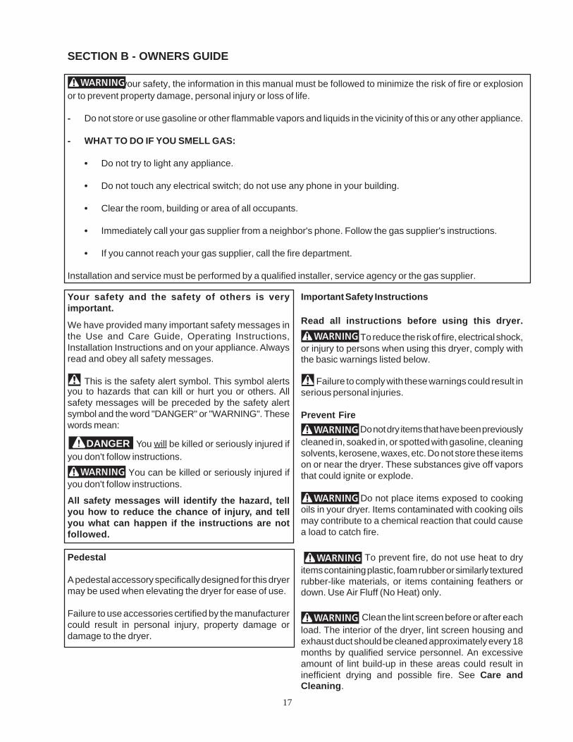
Pedestal
A pedestal accessory specifically designed for this dryermay be used when elevating the dryer for ease of use.
Failure to use accessories certified by the manufacturercould result in personal injury, property damage ordamage to the dryer.
Important Safety Instructions
Read all instructions before using this dryer.
To reduce the risk of fire, electrical shock,or injury to persons when using this dryer, comply withthe basic warnings listed below.
Failure to comply with these warnings could result inserious personal injuries.
Prevent Fire Do not dry items that have been previously
cleaned in, soaked in, or spotted with gasoline, cleaningsolvents, kerosene, waxes, etc. Do not store these itemson or near the dryer. These substances give off vaporsthat could ignite or explode.
Do not place items exposed to cookingoils in your dryer. Items contaminated with cooking oilsmay contribute to a chemical reaction that could causea load to catch fire.
To prevent fire, do not use heat to dryitems containing plastic, foam rubber or similarly texturedrubber-like materials, or items containing feathers ordown. Use Air Fluff (No Heat) only.
Clean the lint screen before or after eachload. The interior of the dryer, lint screen housing andexhaust duct should be cleaned approximately every 18months by qualified service personnel. An excessiveamount of lint build-up in these areas could result ininefficient drying and possible fire. See Care andCleaning.

18
Do not operate the dryer if the lint screenis blocked, damaged or missing. Fire hazard, overheatingand damage to fabrics can occur. If your dryer has adrying rack, always replace the lint screen when finishedusing the drying rack.
Keep area around the exhaust openingand surrounding areas free from the accumulation of lint,dust and dirt.
Do not obstruct the flow of ventilating air.Do not stack or place laundry or throw rugs against thefront or back of the dryer.
Do not spray any type of aerosol into, onor near dryer at any time.
Do not use fabric softeners or products toeliminate static unless recommended by the manufacturerof the fabric softener or product.
Failure to comply with these warnings could result infire, explosion, serious bodily injury and/or damage to therubber or plastic parts of the dryer.
This Use and Care Guide provides general operatinginstructions for your dryer. It also contains informationabout features for several other models. Your dryer maynot have every feature included.
Use the dryer only as instructed in this Use & Care Guideand the Operating Instructions card included with yourdryer.
Avoid fire hazard or electrical shock. Donot use an adaptor plug or extension cord or removegrounding prong from electrical power cord. Failure tofollow this warning can cause serious injury, fire or death.
Note: The instructions appearing in this Owner's Guideare not meant to cover every possible condition andsituation that may occur. Common sense and cautionmust be practiced when installing, operating andmaintaining any appliance.
Protect Children
Do not allow children to play on or in thedryer. Close supervision of children is necessary whenthe dryer is used near children. As children grow, teachthem the proper, safe use of all appliances.
Destroy the carton, plastic bag and otherpacking materials after the dryer is unpacked. Childrenmight use them for play. Cartons covered with rugs,bedspreads or plastic sheets can become airtightchambers.
Keep laundry products out of children'sreach. To prevent personal injury, observe all warningson product labels.
Before the dryer is removed from serviceor discarded, remove the dryer door to prevent accidentalentrapment.
Failure to comply with these warnings could result inserious personal injuries.
Prevent Injury
To prevent shock hazard and assurestability during operation, the dryer must be installed andelectrically grounded by a qualified service person inaccordance with local codes. Installation instructions are
GAS DRYERS:
CORRECTUse this way ONLY
Grounding typewall receptacle
Power supplycord with 3-pronggrounding plug
Do not underany circumstancescut, remove,or bypassthe grounding prongfrom this plug.
CORRECTUse this way ONLY
ELECTRIC DRYERS:
DRYER
FUSED 30 AMP120/240 V OR120/208 VWALLRECEPTACLE
DRYERS E R V I C ECORD
14-30R
19
packed in the dryer for the installer's reference. Refer toINSTALLATION INSTRUCTIONS for detailed groundingprocedures. If the dryer is moved to a new location, haveit checked and reinstalled by a qualified service person.
To prevent personal injury or damage tothe dryer, the electrical power cord of a gas dryer mustbe plugged into a properly grounded and polarized 3-prong outlet. The third grounding prong must neverbe removed. Never ground the dryer to a gas pipe.Do not use an extension cord or an adaptor plug.
ALWAYS disconnect the dryer fromthe electrical supply before attempting any service orcleaning. Failure to do so can result in electrical shockor injury.
Do not use any type spray cleanser whencleaning dryer interior. Hazardous fumes or electricalshock could occur.
To prevent injury, do not reach into thedryer if the drum is moving. Wait until the dryer hasstopped completely before reaching into the drum.
To prevent injury and damage to thedryer:
• All repairs and servicing must be performed byan authorized servicer unless specificallyrecommended in this Owner's Guide. Use onlyauthorized factory parts.
• Do not tamper with controls.
• Do not install or store the dryer where it will beexposed to the weather.
A thermal limiter switch automatically turns off themotor in the unlikely event of an overheated situation(electric dryers only). A service technician must replacethe thermal limiter switch after correcting the fault.
Failure to comply with these warnings could resultin serious personal injuries.
SAVE THESE INSTRUCTIONS
Drying Procedures
• Follow the guidelines below for preparing the load fordrying.
• Read the Operating Instructions card for operatingyour specific model.
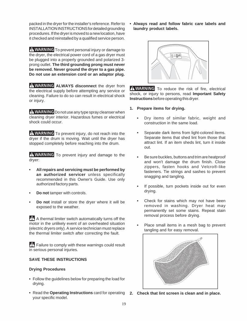
• Always read and follow fabric care labels andlaundry product labels.
To reduce the risk of fire, electricalshock, or injury to persons, read Important SafetyInstructions before operating this dryer.
1. Prepare items for drying.
• Dry items of similar fabric, weight andconstruction in the same load.
• Separate dark items from light-colored items.Separate items that shed lint from those thatattract lint. If an item sheds lint, turn it insideout.
• Be sure buckles, buttons and trim are heatproofand won't damage the drum finish. Closezippers, fasten hooks and Velcro®-likefasteners. Tie strings and sashes to preventsnagging and tangling.
• If possible, turn pockets inside out for evendrying.
• Check for stains which may not have beenremoved in washing. Dryer heat maypermanently set some stains. Repeat stainremoval process before drying.
• Place small items in a mesh bag to preventtangling and for easy removal.
2. Check that lint screen is clean and in place.
20
Features
End of Cycle Signal
A signal will sound at the end of the cycle and periodicallyduring Press Saver at the volume level selected. (somemodels)
Drum Light (some models)
A drum light will come on whenever the door is openedto illuminate the dryer drum during loading andunloading. Closing the door turns off the light.
Reversible Dryer Door
Your dryer is equipped with a reversible door. The doorcan be hinged on the right or left side. Refer to theINSTALLATION INSTRUCTIONS for directions onchanging the door.
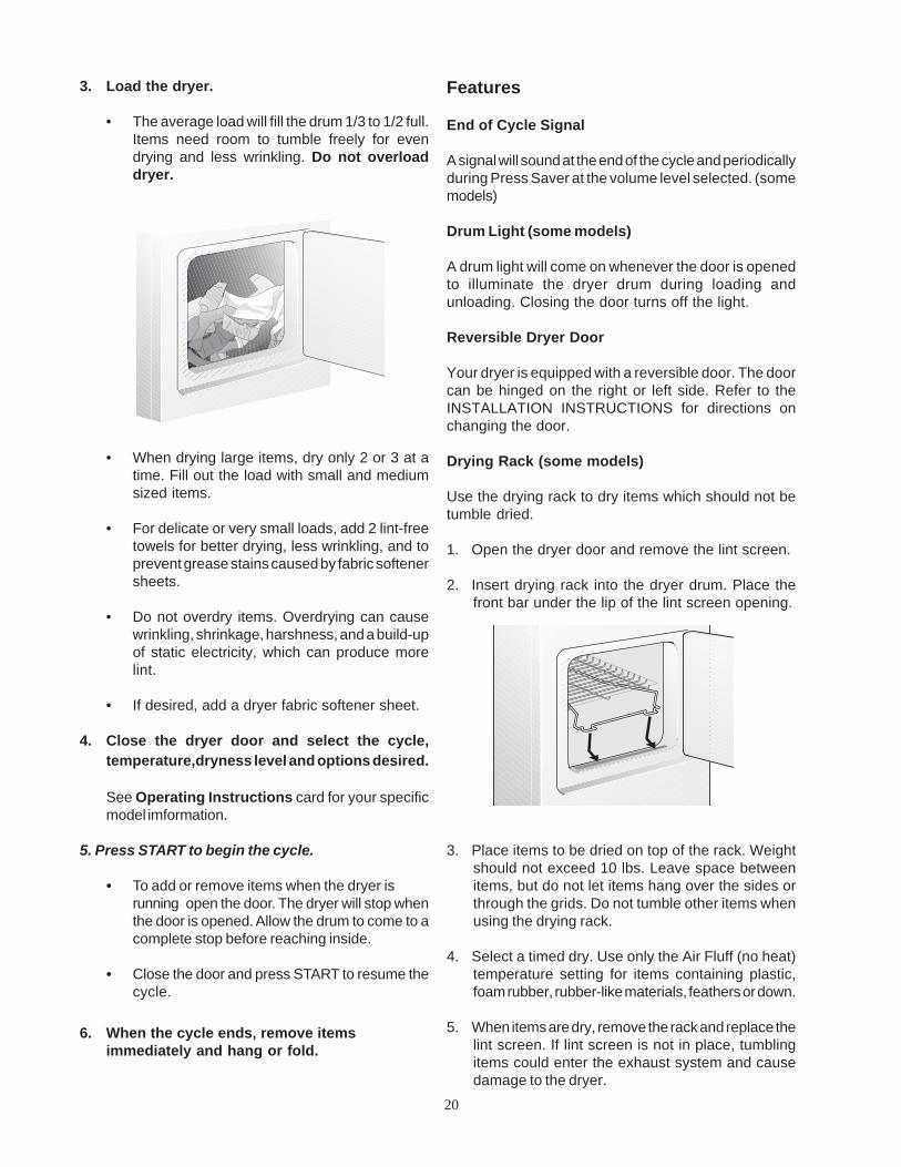
Drying Rack (some models)
Use the drying rack to dry items which should not betumble dried.
1. Open the dryer door and remove the lint screen.
2. Insert drying rack into the dryer drum. Place thefront bar under the lip of the lint screen opening.
3. Place items to be dried on top of the rack. Weightshould not exceed 10 lbs. Leave space betweenitems, but do not let items hang over the sides orthrough the grids. Do not tumble other items whenusing the drying rack.
4. Select a timed dry. Use only the Air Fluff (no heat)temperature setting for items containing plastic,foam rubber, rubber-like materials, feathers or down.
5. When items are dry, remove the rack and replace thelint screen. If lint screen is not in place, tumblingitems could enter the exhaust system and causedamage to the dryer.
3. Load the dryer.
• The average load will fill the drum 1/3 to 1/2 full.Items need room to tumble freely for evendrying and less wrinkling. Do not overloaddryer.
• When drying large items, dry only 2 or 3 at atime. Fill out the load with small and mediumsized items.
• For delicate or very small loads, add 2 lint-freetowels for better drying, less wrinkling, and toprevent grease stains caused by fabric softenersheets.
• Do not overdry items. Overdrying can causewrinkling, shrinkage, harshness, and a build-upof static electricity, which can produce morelint.
• If desired, add a dryer fabric softener sheet.
4. Close the dryer door and select the cycle,temperature,dryness level and options desired.
See Operating Instructions card for your specificmodel imformation.
5. Press START to begin the cycle.
• To add or remove items when the dryer isrunning open the door. The dryer will stop whenthe door is opened. Allow the drum to come to acomplete stop before reaching inside.
• Close the door and press START to resume thecycle.
6. When the cycle ends, remove itemsimmediately and hang or fold.

21
Common Drying Problems
Many drying problems involve poor cleaning results, poor soil and stain removal, residues of lint and scum, andfabric damage. For satisfactory drying results, follow these suggestions provided by The Soap and DetergentAssociation.
PROBLEM
Greasy, oilystains
Lint
Pilling(Fibers breakoff, ball upand cling tofabric.)
Shrinking
Wrinkling
POSSIBLE CAUSES
• Fabric softener sheet.
• Overloading.• Overdrying causes
static electricity.• Lint screen not clean
when cycle began.• Lint is attached to
"pills."
• Pilling is normal withsynthetic andpermanent pressfabrics. This is due toabrasion from normalwear.
• Overdrying.
• Overloading.• Leaving items in dryer
after cycle ends.
SOLUTIONS
• Rub fabric softener stainswith bar soap. Rinse andrewash.
• Reduce load size andrewash using liquid fabricsoftener in the final rinse.
• Or, add a fabric softenersheet and tumble withoutheat.
• Use lint brush or roller toremove lint.
• Use a lint brush or shaverto remove pills.
• Irreversible condition.
• Reduce load size andtumble at medium or lowheat for 5-10 minutes.
• Remove itemsimmediately. Hang or fold.
PREVENTIVE MEASURES
• Add a few bath towels to smallloads for proper tumbling.
• Some "silk-like" fabrics shouldbe air dried.
• Use proper drying temperature.• Place fabric softener sheet on
top of load before starting thedryer.
• Do not overload dryer.• Use fabric softener in washer or
dryer to reduce static electricity.• Remove items when they are
slightly damp to avoidoverdrying.
• Check that lint screen is cleanand in place.
• Use fabric softener to lubricatefibers.
• When ironing, use spray starchor fabric finish on collars andcuffs.
• Turn items inside out to reduceabrasion.
• Follow fabric care labeldirections.
• If shrinking is a concern, checkload often.
• Remove items while slightlydamp and hang or lay flat tocomplete drying.
• Block knits into shape.
• Do not overload dryer.• Remove items as soon as cycle
ends.

22
Care and Cleaning
To reduce risk of fire or serious injury topersons or property, comply with the basic warningslisted in Important Safety Instructions and those listedbelow.
• Before cleaning the dryer interior, unplug theelectrical power cord to avoid electrical shockhazards.
• Do not use any type spray cleanser when cleaningdryer interior. Hazardous fumes or electrical shockcould occur.
Inside
• Clean the lint screen after every load. Lint build-upin the screen restricts air flow, which causes longerdrying times. The screen is located at the bottom ofthe door opening. Remove by pulling straight up.Remove the lint and replace the screen.
• Occasionally a waxy build-up may form on the lintscreen from using dryer-added fabric softenersheets. To remove this build-up, wash the lintscreen in warm, soapy water. Dry thoroughly andreplace. Do not operate the dryer without the lintscreen in place.
• If the dryer drum becomes stained from noncolorfastfabrics, clean the drum with a damp cloth and a mildliquid household cleanser. Remove cleanser residuebefore drying the next load.
• Every 18 months an authorized servicer shouldclean the dryer cabinet interior and exhaust duct.These areas can collect lint and dust over time. Anexcessive amount of lint build-up could result ininefficient drying and possible fire hazard.
Outside
• Clean the cabinet with mild soap and water. Neveruse harsh, gritty or abrasive cleansers.
• If the cabinet becomes stained, clean with dilutedchlorine bleach [1/2 cup(120 ml) in 1 quart (.95 liter)water]. Rinse several times with clear water.
• Remove glue residue from tape or labels with amixture of warm water and mild detergent. Or,touch residue with the sticky side of the tape orlabel.
• Before moving the dryer, place a strip of cardboardor thin fiberboard under the front leveling legs toprevent damage to floor.
Do not store or place laundry products on top of dryer atany time. They can damage the finish or controls.
23
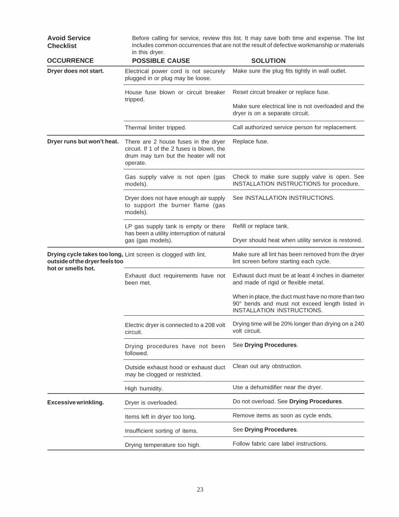
Avoid ServiceChecklist
Before calling for service, review this list. It may save both time and expense. The listincludes common occurrences that are not the result of defective workmanship or materialsin this dryer.
OCCURRENCE SOLUTIONMake sure the plug fits tightly in wall outlet.
Reset circuit breaker or replace fuse.
Make sure electrical line is not overloaded and thedryer is on a separate circuit.
Call authorized service person for replacement.
Replace fuse.
Check to make sure supply valve is open. SeeINSTALLATION INSTRUCTIONS for procedure.
See INSTALLATION INSTRUCTIONS.
Refill or replace tank.
Dryer should heat when utility service is restored.
Make sure all lint has been removed from the dryerlint screen before starting each cycle.
Exhaust duct must be at least 4 inches in diameterand made of rigid or flexible metal.
When in place, the duct must have no more than two90° bends and must not exceed length listed inINSTALLATION INSTRUCTIONS.
Drying time will be 20% longer than drying on a 240volt circuit.
See Drying Procedures.
Clean out any obstruction.
Use a dehumidifier near the dryer.
Do not overload. See Drying Procedures.
Remove items as soon as cycle ends.
See Drying Procedures.
Follow fabric care label instructions.
POSSIBLE CAUSEElectrical power cord is not securelyplugged in or plug may be loose.
House fuse blown or circuit breakertripped.
Thermal limiter tripped.
There are 2 house fuses in the dryercircuit. If 1 of the 2 fuses is blown, thedrum may turn but the heater will notoperate.
Gas supply valve is not open (gasmodels).
Dryer does not have enough air supplyto support the burner flame (gasmodels).
LP gas supply tank is empty or therehas been a utility interruption of naturalgas (gas models).
Lint screen is clogged with lint.
Exhaust duct requirements have notbeen met.
Electric dryer is connected to a 208 voltcircuit.
Drying procedures have not beenfollowed.
Outside exhaust hood or exhaust ductmay be clogged or restricted.
High humidity.
Dryer is overloaded.
Items left in dryer too long.
Insufficient sorting of items.
Drying temperature too high.
Dryer does not start.
Dryer runs but won't heat.
Drying cycle takes too long,outside of the dryer feels toohot or smells hot.
Excessive wrinkling.

24
Avoid ServiceChecklist
Before calling for service, review this list. It may save both time and expense. The list includescommon occurrences that are not the result of defective workmanship or materials in this dryer.
OCCURRENCE
Scratching orchipping of thedrum finish.
POSSIBLE CAUSE
Foreign objects such as coins, pins, clipsor buttons are inside the dryer.Permanently attached items such as beltbuckles, zippers and fasteners may behitting the inside of the drum.
SOLUTION
Always remove foreign objects from pocketsbefore laundering. Remove objects from drumand restart dryer.It may be necessary to baste a scrap ofmaterial securely around ornaments beforedrying to prevent scratching and damage tothe dryer.Drum damage caused by foreign objects orpermanently attached items is not coveredby the warranty.

25
THE CONSUMER WILL BERESPONSIBLE FOR:
Costs of service calls that are listed under IMPORTANTRESPONSIBILITIES OF THE CONSUMER.*
Costs of the technician's travel to the home and anycosts for pick up and delivery of the appliance requiredbecause of service.
WARRANTYPERIOD
One year from originalpurchase date.
Time period listed above.
FRIGIDAIRE, THROUGH ITS AUTHORIZEDSERVICERS, WILL:
Pay all costs for repairing or replacing any partsof this appliance which prove to be defectivein materials or workmanship.
All of the provisions of the full warranty aboveand the exclusions listed below apply.
FULL ONE-YEARWARRANTY
LIMITED WARRANTY(Applicable to theState of Alaska)
This warranty applies only to products in ordinary household use, and the consumer is responsiblefor the items listed below:
1. Proper use of the appliance in accordance with instructions provided with the product.2. Proper installation by an authorized servicer in accordance with instructions provided with the
appliance and in accordance with all local plumbing, electrical and/or gas codes.3. Proper connection to a grounded power supply of sufficient voltage, replacement of blown fuses,
repair of loose connections or defects in house wiring.4. Expenses for making the appliance accessible for servicing, such as removal of trim, cupboards,
shelves, etc., which are not a part of the appliance when it was shipped from the factory.5. Damages to finish after installation.6. Replacement of light bulbs and/or fluorescent tubes (on models with these features).
This warranty does not cover the following:
1. CONSEQUENTIAL OR INCIDENTAL DAMAGES SUCH AS PROPERTY DAMAGE ANDINCIDENTAL EXPENSES RESULTING FROM ANY BREACH OF THIS WRITTEN OR ANYIMPLIED WARRANTY.Note: Some states do not allow the exclusion or limitation of incidental or consequential damages,so this limitation or exclusion may not apply to you.
2. Service calls which do not involve malfunction or defects in workmanship or material, or forappliances not in ordinary household use. The consumer shall pay for such service calls.
3. Damages caused by services performed by servicers other than Frigidaire or its authorizedservicers; use of parts other than genuine Frigidaire Home Products parts; obtained frompersons other than such servicers; or external causes such as abuse, misuse, inadequatepower supply or acts of God.
4. Products with original serial numbers that have been removed or altered and cannot be readilydetermined.
Keep your bill of sale, delivery slip, or some other appropriate payment record. The date on the billestablishes the warranty period should service be required. If service is performed, it is in your bestinterest to obtain and keep all receipts. This written warranty gives you specific legal rights. You mayalso have other rights that vary from state to state. Service under this warranty must be obtained bycontacting Frigidaire Home Products:
800 • 944 • 9044Frigidaire Home ProductsP.O. Box 212378Augusta, GA 30917
Product features or specifications as described or illustrated are subject to change without notice.All warranties are made by White Consolidated Industries, Inc. This warranty applies only in the 50states of the U.S.A. and Puerto Rico.
Your appliance is warranted by Frigidaire Home Products, a division of White Consolidated Industries, Inc. We authorize no person to changeor add to any of our obligations under this warranty. Our obligations for service and parts under this warranty must be performed by Frigidaireor an authorized Frigidaire servicer.
FRIGIDAIRE DRYER WARRANTYYour Frigidaire product is protected by this warranty
Sample warranty - always checkwarranty with product
* IMPORTANTRESPONSIBILITIESOF THE CONSUMER
EXCLUSIONS
IF YOU NEEDSERVICE

26
For your safety the information in this manual must be followed to minimizethe risk of fire or explosion or to prevent property damage, personal injury or loss of life.
- Do not store or use gasoline or other flammable vapors and liquid in the vicinity of thisor any other appliance.
- WHAT TO DO IF YOU SMELL GAS
· Do not try to light any appliance.
· Do not touch any electrical switch; do not use any phone in your building.
· Clear the room, building or area of all occupants.
· Immediately call your gas supplier from a neighbor’s phone. Follow the gas supplier'sinstructions.
· If you cannot reach your gas supplier, call the fire department.
Installation and service must be performed by a qualified installer, service agency orthe gas supplier.
Before beginning installation, carefully read these instructions. This will simplify the installation and ensure thedryer is installed correctly and safely. Leave these instructions near the Dryer after installation for future reference.
NOTE: The electrical service to the Dryer must conform with local codes and ordinances and the latest editionof the National Electrical Code, ANSI/NFPA 70.
NOTE: The gas service to the Dryer must conform with local codes and ordinances and the latest edition of theNational Fuel Gas Code ANSI Z223.1.
NOTE: The Dryer is designed under ANSI Z 21.5.1 or ANSI/UL 2158 - CAN/CSA C22.2 (latest editions) forHOME USE only. This Dryer is not recommended for commercial applications such as restaurants or beautysalons, etc.
SECTION C - INSTALLATION INSTRUCTIONS GAS & ELECTRIC DRYER

27
GAS Dryer
CIRCUIT - Individual 15 amp. branch circuit fused with a15 amp. maximum time delay fuse or circuit breaker.
POWER SUPPLY - 3 wire, 120 volt single phase, 60 Hz,Alternating Current.
POWER SUPPLY CORD - The dryer is equipped with a120 volt 3-wire power cord.
EXHAUST SYSTEM REQUIREMENTS
Use only 4 inch (10.2 cm) diameter (minimum) rigid orflexible metal duct and approved vent hood which has aswing-out damper(s) that open when the dryer is inoperation. When the dryer stops, the dampersautomatically close to prevent drafts and the entrance ofinsects and rodents. To avoid restricting the outlet,maintain a minimum of 12 inches (30.5 cm) clearancebetween the vent hood and the ground or any otherobstruction.
The following are specificrequirements for proper and safe operation of yourdryer. Failure to follow these instructions cancreate excessive drying times and fire hazards.
Do not use plastic flexible duct to exhaust thedryer. Excessive lint can build up inside exhaust systemand create a fire hazard and restrict air flow. Restrictedair flow will increase dryer times. If your present systemis made up of plastic duct or metal foil duct, replace itwith a rigid or flexible metal duct. Ensure the presentduct is free of any lint prior to installing dryer duct.
PRE-INSTALLATION REQUIREMENTS
Tools and Materials Required for Installation:
1. Phillips head screwdriver.
2. Channel-lock adjustable pliers.
3. Carpenter's level.
4. Flat or straight blade screwdriver.
5. Duct tape.
6. Rigid or flexible metal 4 inch (10.2 cm) duct.
7. Vent hood.
8. Pipe thread sealer (Gas).
9. Plastic knife
ELECTRICAL REQUIREMENTSELECTRIC Dryer
CIRCUIT - Individual 30 amp. branch circuit fused with30 amp. minimum time delay fuses or circuit breakers.
POWER SUPPLY - 3 or 4 wire, 240 volt, single phase,60 Hz, Alternating Current.
POWER SUPPLY CORD KIT - The dryer MUSTemploy a 3-conductor power supply cord NEMA 10-30type SRDT rated at 240 volt AC minimum, 30 amp.,with 3 open end spade lug connectors with upturnedends or closed loop connectors OR a 4-conductor powersupply cord NEMA 14-30 type SRDT or ST (as required)rated at 240 volt AC minimum, 30 amp., with 4 open endspade lug connectors with upturned ends or closed loopconnectors and marked for use with clothes dryers. Ifbeing installed in a manufactured (mobile) home,thedryer MUST employ a 4-conductor power supplycordNEMA 14-30 type SRDT or ST (as required) rated at 240volt AC minimum, 30 amp., with 4 open end spade lugconnectors with upturned ends or closed loop connectorsand marked for use with clothes dryers (See ELECTRICALCONNECTIONS FOR for additional instructions).
OUTLET RECEPTACLE - NEMA 10-30R (3wire)receptacle or NEMA 14-30R (4wire) receptacle to belocated so the power supply cord is accessible whenthe dryer is in the installed position.
NOTE: Do not underany circumstancesremove groundingprong from plug.
GROUNDING PRONG
NEMA 10-30R NEMA 14-30R

28
If the dryer is not exhausted outdoors, somefine lint will be expelled into the laundry area. Anaccumulation of lint in any area of the home can createa health and fire hazard. The dryer exhaust systemMUST be exhausted to the outside of the dwelling!
Do not allow combustible materials (forexample: clothing, draperies/curtains, paper) tocome in contact with exhaust system. The dryerMUST NOT be exhausted into a chimney, a wall, a ceiling,or any concealed space of a building which canaccumulate lint, resulting in a fire hazard.
Exceeding the length of duct pipe or number ofelbows allowed in the "MAXIMUM LENGTH" chartscan cause an accumulation of lint in the exhaust system.Plugging the system could create a fire hazard, as wellas increase drying times.
Do not screen the exhaust ends of the ventsystem, nor use any screws or rivets to assemblethe exhaust system. Lint can become caught in thescreen, on the screws or rivets, clogging the duct workand creating a fire hazard as well as increasing dryingtimes. Use an approved vent hood to terminate the ductoutdoors, and seal all joints with duct tape. All maleduct pipe fittings MUST be installed downstream withthe flow of air.
Explosion hazard. Do not install thedryer where gasoline or other flammables are keptor stored. If the dryer is installed in a garage, it must bea minimum of 18 inches (45.7 cm) above the floor. Failureto do so can result in death, explosion, fire or burns.
(6.35 cm)2½"
(6.35 cm)2½"
VENT HOOD TYPE(Preferred)
MAXIMUM LENGTHof 4” (10.2 cm) Dia. Flexible Metal Duct
Number of90°
Turns(10.2 cm)
Louvered
VENT HOOD TYPE(Preferred)
Number of90°
Turns
MAXIMUM LENGTHof 4” (10.2 cm) Dia. Rigid Metal Duct
4”(10.2 cm)
Louvered
0 60 ft. (18.28 m) 48 ft.(14.63 m)1 52 ft. (15.84 m) 40 ft.(12.19 m)2 44 ft. (13.41 m) 32 ft. (9.75 m)3 32 ft. (9.75 m) 24 ft. (7.31 m)4 28 ft. (8.53 m) 16 ft. (4.87 m)
0 30 ft. (9.14 m) 18 ft. (5.49 m)1 22 ft. (6.71 m) 14 ft. (4.27 m)2 14 ft. (4.27 m) 10 ft. (3.05 m)3 NOT RECOMMENDED
INSTALL MALE FITTINGS IN CORRECT DIRECTION
In installations where the exhaust system is not de-scribed in the charts, the following method must beused to determine if the exhaust system is acceptable:
1. Connect an inclined or digital manometer betweenthe dryer and the point the exhaust connects tothe dryer.
2. Set the dryer timer and temperature to air fluff (cooldown) and start the dryer.
3. Read the measurement on the manometer.
4. The system back pressure MUST NOT be higherthan 0.75 inches of water column. If the systemback pressure is less than 0.75 inches of watercolumn, the system is acceptable. If themanometer reading is higher than 0.75 inches ofwater column, the system is too restrictive and theinstallation is unacceptable.
Although vertical orientation of the exhaust system isacceptable, certain extenuating circumstances couldaffect the performance of the dryer:
• Only the rigid metal duct work should be used.
• Venting vertical through a roof may expose theexhaust system to down drafts causing an increasein vent restriction.
• Running the exhaust system through anuninsulated area may cause condensation andfaster accumulation of lint.
• Compression or crimping of the exhaust systemwill cause an increase in vent restriction.
The exhaust system should be inspected and cleaned aminimum of every 18 months with normal usage. Themore the dryer is used, the more often you should checkthe exhaust system and vent hood for proper operation.
C O R R E C TC O R R E C TC O R R E C TC O R R E C TC O R R E C T I N C O R R E C TI N C O R R E C TI N C O R R E C TI N C O R R E C TI N C O R R E C TCORRECT INCORRECTCORRECT INCORRECT

29
EXHAUST DIRECTION
All dryers shipped from the factory are set up for rearexhausting. However, on electric dryers, exhausting canbe to the right or left side of the cabinet or the bottomof the dryer. On gas dryers, exhausting can be to theright side of the cabinet or the bottom of the dryer.Directional exhausting can be accomplished byinstalling Exhaust Kit, P/N 131456800, availablethrough your parts distributor. Follow the instructionssupplied with the kit.
EXHAUST DUCT LOCATING DIMENSIONS
GAS SUPPLY REQUIREMENTS
Replace copper connecting pipe thatis not plastic-coated. Stainless steel or plastic-coated brass MUST be used.1. Installation MUST conform with local codes, or in
the absence of local codes, with the National FuelGas Code, ANSI Z223.1 (latest edition)
2. The gas supply line should be of 1/2 inch (1.27 cm)pipe.
3. If codes allow, flexible metal tubing may be usedto connect your dryer to the gas supply line. Thetubing MUST be constructed of stainless steel orplastic-coated brass.
4. The gas supply line MUST have an individualshutoff valve.
5. A 1/8 inch (0.32 cm) N.P.T. plugged tapping,accessible for test gauge connection, MUST beinstalled immediately upstream of the gas supplyconnection to the dryer.
6. The dryer MUST be disconnected from the gassupply piping system during any pressure testingof the gas supply piping system at test pressures inexcess of 1/2 psig (3.45 kPa).
7. The dryer MUST be isolated from the gas supplypiping system during any pressure testing of the gassupply piping system at test pressures equal to orless than 1/2 psig (3.45 kPa).
LOCATION OF YOUR DRYERDO NOT INSTALL YOUR DRYER:
1. In an area exposed to dripping water or outsideweather conditions.
2. In an area where it will come in contact with curtains,drapes, or anything that will obstruct the flow ofcombustion and ventilation air.
3. On carpet. Floor MUST be solid with a maximumslope of 1 inch (2.54 cm).
INSTALLATION IN RECESS OR CLOSET
1. A dryer installed in a bedroom, bathroom, recess orcloset, MUST be exhausted outdoors.
2. No other fuel burning appliance shall be installed inthe same closet as the Gas dryer.
3. Your dryer needs the space around it for properventilation.
DO NOT INSTALL YOUR DRYER IN A CLOSETWITH A SOLID DOOR.
4. A minimum of 120 square inches (774.2 square cm)of opening, equally divided at the top and bottom ofthe door, is required. Air openings are required tobe unobstructed when a door is installed. A louvereddoor with equivalent air openings for the full length ofthe door is acceptable.
MINIMUM INSTALLATION CLEARANCES(Inches) SIDES REAR TOP FRONTAlcove 0 (0 cm) 0 (0 cm) 15 (38.1 cm)Closet 0 (0 cm) 0 (0 cm) 15 (38.1 cm) 1 (2.54 cm)
Closet door ventilation required: 2 louvered openingseach 60 square inches (387 square centimeters) — 3inches (7.6 cm) from bottom and top of door.
NOTE: Under counter and stack models - 0 inches (0 cm) for sides, rear, and top.
THIS DRYER MUST BE EXHAUSTED OUTDOORS.5. The following illustrations show minimum clearance
dimensions for proper operation in a recess or closetinstallation.
SAME AS OTHERSAME AS OTHERSAME AS OTHERSAME AS OTHERSAME AS OTHERS I D ES I D ES I D ES I D ES I D E
( 9 . 5( 9 . 5( 9 . 5( 9 . 5( 9 . 5c m )c m )c m )c m )c m )
4 3/4 3/4 3/4 3/4 3/8 "8 "8 "8 "8 "
( 1 1( 1 1( 1 1( 1 1( 1 1c m )c m )c m )c m )c m )
5 7/5 7/5 7/5 7/5 7/8 "8 "8 "8 "8 "
( 1 5( 1 5( 1 5( 1 5( 1 5c m )c m )c m )c m )c m )1 31 31 31 31 3
1 /1 /1 /1 /1 /2 "2 "2 "2 "2 "
( 3 4( 3 4( 3 4( 3 4( 3 4c m )c m )c m )c m )c m )
3 3/3 3/3 3/3 3/3 3/4 "4 "4 "4 "4 "
( 9 . 5( 9 . 5( 9 . 5( 9 . 5( 9 . 5c m )c m )c m )c m )c m )
3 3/3 3/3 3/3 3/3 3/4 "4 "4 "4 "4 "
( 9 . 5( 9 . 5( 9 . 5( 9 . 5( 9 . 5c m )c m )c m )c m )c m )

30
0" (00" (00" (00" (00" (0c m )c m )c m )c m )c m )
1" (2.541" (2.541" (2.541" (2.541" (2.54c m )c m )c m )c m )c m )
NOTE: Under counter and stack models - 0 inches (0 cm)for sides, rear, and top.
CLOSET DOOR
1" (2.54 cm)
0" (0 cm)
0" (0 cm)60 SQ. IN.(387.1 SQ.
60 SQ. IN.(387.1 SQ. CM)
15"(38.1 cm)
0" (00" (00" (00" (00" (0c m )c m )c m )c m )c m )
0" (0 cm)0" (0 cm)0" (0 cm)0" (0 cm)0" (0 cm)

31

32
MOBILE HOME INSTALLATION
1. Dryer MUST be exhausted outside (outdoors, notbeneath the mobile home) using metal ducting thatwill not support combustion. Metal ducting mustbe 4 inches (10.16 cm) in diameter with noobstructions. Rigid metal duct is preferred.
2. If dryer is exhausted through the floor and areabeneath the mobile home is enclosed, the exhaustsystem MUST terminate outside the enclosurewith the termination securely fastened to the mobilehome structure.
3. When installing a gas dryer into a mobile home, aprovision must be made for outside make up air.This provision is to be not less than twice the areaof the dryer exhaust outlet.
4. This dryer MUST be fastened to the floor. MobileHome Installation Kit No. 346764 is available fromyour dealer.
5. Refer to other important venting requirements.
6. Installation MUST conform to current ManufacturedHome Construction & Safety Standard (which is aFederal Regulation Title 24 CFR-Part 32-80) or whensuch standard is not applicable, with AmericanNational Standard for Mobile Homes.
The dryer is designed under ANSI Z21.5.1or ANSI?UL2158 - CAN/CSA C22.2 (latesteditions) for HOME USE only.
UNPACKING
1. Using the four shipping carton corner posts (two on eachside), carefully lay the dryer on its left side and removefoam shipping base.
To prevent damage, do not use the controlpanel as a means to pick up or move the dryer.
2. Return the dryer to an upright position.
REVERSING DOOR SWING
Your dryer is designed so the door swing may be reversedat any time without additional parts. Conversion isaccomplished by transferring hinges to the opposite side ofthe cabinet.
PACKING
FOAMSHIPPINGPAD

33
“Window Door” Reversal Instructions:
1. Open the dryer door. Remove the four hinge hole plugsfrom the left side of the door opening. Retain the plugsfor use later. NOTE: You may need a plastic knife tohelp pull out the plugs. Be careful not to scratch thepaint.
2. Remove the four screws that secure the door hingesto the dryer front panel. NOTE: Remove one screwfrom each of the two hinges first. Hold the door firmlybefore removing the last two screws.
“Solid Door “ Reversal Instructions:
1. Open the dryer door. Remove the four hinge holeplugs from the left side of the door opening. Placenearby for future installation. NOTE: You may needa plastic knife to help pull out the plugs. Be carefulnot to scratch the paint.
2. Remove the four screws that secure the door hingesto the dryer front panel (see below). NOTE:Remove one screw from each of the two hingesfirst. Hold the door firmly before removing the lasttwo screws.
3. Rotate the door 180° and reinstall the door hingesto the dryer front panel with the four screws.
4. Install the four hinge hole plugs in the open screwholes on the right side of the door opening.
3. Install the plugs from Step 1 into the holes left byremoving the door in Step 2.
4. Remove the two handle hole plugs from the door.Retain the plugs for use later. NOTE: You mayneed a plastic knife to help remove the plugs. Becareful to avoid scratching the paint.
5. Remove the two handle screws and remove thehandle by pulling straight out from door.
6. Install the plugs from Step 3 into the holes left byremoving the handle screws in Step 4.

34
7. Lay the door on a flat surface and support the edgesof the door to keep it from turning. Apply moderatedownward pressure on the lens with both hands androtate it 180°. Align the handle holes in the lens withthe handle holes in the transition ring.
8. Install the handle and screws removed in Step 4.
9. Remove the two hinges and reinstall the four screws.Note the installation orientation of the hinges.
10. Remove the screws from the opposite side of the door and use them to reinstall the hinges.
11. Install the door assembly on the left side of the door opening using the four screws removed in Step 2.
35
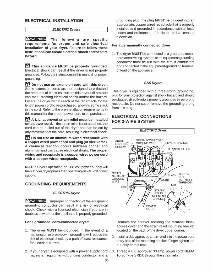
ELECTRICAL INSTALLATION
ELECTRIC Dryers
The following are specificrequirements for proper and safe electricalinstallation of your dryer. Failure to follow theseinstructions can create electrical shock and/or a firehazard.
This appliance MUST be properly grounded.Electrical shock can result if the dryer is not properlygrounded. Follow the instructions in this manual for propergrounding.
Do not use an extension cord with this dryer.Some extension cords are not designed to withstandthe amounts of electrical current this dryer utilizes andcan melt, creating electrical shock and/or fire hazard.Locate the dryer within reach of the receptacle for thelength power cord to be purchased, allowing some slackin the cord. Refer to the pre-installation requirements inthis manual for the proper power cord to be purchased.
A U.L. approved strain relief must be installedonto power cord. If the strain relief is not attached, thecord can be pulled out of the dryer and can be cut byany movement of the cord, resulting in electrical shock.
Do not use an aluminum wired receptacle witha copper wired power cord and plug (or vice versa).A chemical reaction occurs between copper andaluminum and can cause electrical shorts. The properwiring and receptacle is a copper wired power cordwith a copper wired receptacle.
NOTE: Dryers operating on 208 volt power supply willhave longer drying times than operating on 240 volt powersupply.
GROUNDING REQUIREMENTS
ELECTRIC Dryer
Improper connection of the equipmentgrounding conductor can result in a risk of electricalshock. Check with a licensed electrician if you are indoubt as to whether the appliance is properly grounded.
For a grounded, cord-connected dryer:
1. The dryer MUST be grounded. In the event of amalfunction or breakdown, grounding will reduce therisk of electrical shock by a path of least resistancefor electrical current.
2. If your dryer is equipped with a power supply cordhaving an equipment-grounding conductor and a
grounding plug, the plug MUST be plugged into anappropriate, copper wired receptacle that is properlyinstalled and grounded in accordance with all localcodes and ordinances. If in doubt, call a licensedelectrician.
For a permanently connected dryer:
1. The dryer MUST be connected to a grounded metal,permanent wiring system; or an equipment groundingconductor must be run with the circuit conductorsand connected to the equipment-grounding terminalor lead on the appliance.
GAS Dryers
This dryer is equipped with a three-prong (grounding)plug for your protection against shock hazard and shouldbe plugged directly into a properly grounded three-prongreceptacle. Do not cut or remove the grounding prongfrom this plug.
ELECTRICAL CONNECTIONSFOR 3-WIRE SYSTEM
ELECTRIC Dryer
1. Remove the screws securing the terminal blockaccess cover and the strain relief mounting bracketlocated on the back of the dryer upper corner.
2. Install a U.L. approved strain relief into the power cordentry hole of the mounting bracket. Finger tighten thenut only at this time.
3. Thread a U.L. approved 30 amp. power cord, NEMA10-30 Type SRDT, through the strain relief.
NUT
TIGHTENNUTTO THESETHREADS
POWERCORD
RED
WHITE
BLACK
TERMINAL BLOCK
SILVER TERMINALGREENGROUNDSCREW
GREEN POWER CORDGROUND WIRE
GREENNEUTRALGROUNDWIRE
STRAINRELIEF
MOUNTINGBRACKET

36
3. Remove the green neutral ground wire from thegreen ground screw located above the terminalblock.
4. Thread a U.L. approved 30 amp power cord, NEMA14-30 type ST or SRDT through the strain relief.
5. Attach the green power cord ground wire to thecabinet with the green ground screw.
6. Attach the white (neutral) power cord conductor fromthe power cord and the green ground wire from thedryer harness to the silver-colored center terminalon the terminal block. Tighten the screw securely.
7. Attach the red and black power cord conductors tothe outer brass-colored terminals on the terminalblock.
Do not make a sharp bend or crimpwiring/ conductor at the connections.8. Tighten the screws securing the cord restraint firmly
against the power cord.
9. Tighten the strain relief nut securely so the strainrelief does not turn.
10.Reinstall the terminal block access cover.
GAS CONNECTION
1. Remove the shipping cap from gas pipe at the rearof the dryer.
NOTE: DO NOT connect the dryer to L.P. gas servicewithout converting the gas valve. An L.P.conversion kit must be installed by a qualifiedgas technician.
2. Connect a 1/2 inch (1.27 cm) I.D. semi-rigid orapproved pipe from gas supply line to the 3/8 inch(0.96 cm) pipe located on the back of the dryer. Usea 1/2 inch to 3/8 inch (1.27 cm to 0.96 cm) reducerfor a connection. Apply an approved thread sealerthat is resistant to the corrosive action of liquefiedgases on all pipe connections.
POWER CORD
TIGHTEN NUTTO THESETHREADS
STRAINRELIEFMOUNTINGBRACKET
GREENGROUNDSCREW
NUT
SILVER TERMINALGREENNEUTRALGROUNDWIRE
4. Attach the power cord neutral (center wire) conductorto the silver colored center terminal on the terminalblock. Tighten the screw securely.
5. Attach the remaining two power cord outerconductors to the outer brass colored terminals onthe terminal block. Tighten both screws securely.
Do not make a sharp bend or crimpwiring/ conductor at connections.
6. Reattach the strain relief mounting bracket to theback of the dryer with two screws. Tighten screwssecurely.
7. Tighten the screws securing the cord restraint firmlyagainst the power cord.
8. Tighten the strain relief nut securely so that the strainrelief does not turn.
9. Reinstall the terminal block cover.
ELECTRICAL CONNECTIONSFOR 4-WIRE SYSTEM
ELECTRIC Dryer
1. Remove the screws securing the terminal blockaccess cover and the strain relief mounting bracketlocated on the back of the dryer upper corner.
2. Install a U.L. approved strain relief in the entry holeof the mounting bracket. Finger tighten the nut onlyat this time.
WHITE NEUTRAL
GREEN GROUND
30 AMP NEMA 14-30 TYPE SRDT OR ST
TYPICAL 4CONDUCTORCORD
RED 240V
BLACK 240VTYPICAL 4CONDUCTORRECEPTACLE

37
7. Place these instructions in a location near the dryerfor future reference.
REPLACEMENT PARTS
If replacements parts are needed for your dryer, contactthe source where you purchased your dryer, call 1-800-944-9044, or visit our website, www.frigidaire.com, forthe Frigidaire Company Authorized Parts Distributornearest you.
Label all wires prior to disconnectionwhen servicing controls. Wiring errors can causeimproper and dangerous operation. Verify properoperation after servicing.
Destroy the carton and plastic bags afterthe dryer is unpacked. Children might use them for play.Cartons covered with rugs, bedspreads, or plastic sheetscan become airtight chambers causing suffocation. Placeall materials in a garbage container or make materialsinaccessible to children.
The instructions in this manual and allother literature included with this dryer are not meantto cover every possible condition and situation thatmay occur. Good safe practice and caution MUST beapplied when installing, operating and maintaining anyappliance.
3. Open the shutoff valve in the gas supply line to allowgas to flow through pipe.
4. Test all connections by brushing on a soapy watersolution. NEVER TEST FOR GAS LEAKS WITH ANOPEN FLAME.
GENERAL INSTALLATION
1. Connect the exhaust duct to outside exhaustsystem. Use duct tape to seal all joints.
2. With the dryer in its final position, adjust one or moreof the legs until the dryer is resting solid on all fourlegs. Place a level on top of the dryer. THE DRYERMUST BE LEVEL AND RESTING SOLID ON ALLFOUR LEGS.
3. Plug the power cord into a grounded outlet.
NOTE: Check to ensure the power is off at circuitbreaker/ fuse box before plugging the power cordinto the outlet.
4. Turn on the power at circuit breaker/fuse box.
Before operating the dryer, makesure the dryer area is clear and free fromcombustible materials, gasoline, and otherflammable vapors. Also see that nothing (such asboxes, clothing, etc.) obstructs the flow ofcombustion and ventilation air.
5. Run the dryer through a cycle check for properoperation.
NOTE: On gas dryers, before the burner will light, it isnecessary for the gas line to be bled of air. Ifthe burner does not light within 45 seconds thefirst time the dryer is turned on, the safety switchwill shut the burner off. If this happens, turn thetimer to "OFF" and wait 5 minutes before makinganother attempt to light.
6. If your dryer does not operate, please review the"Avoid Service Checklist" located in your Use andCare Guide before calling for service.
VALVE OPEN/GAS FLOW POSITION

38
SECTION D - Washer & DryerPedestal Installation Instructions
IMPORTANT: Read and save these instructions.
This kit is intended to be installed by persons having electrical and mechanical training and a level of knowledge considered acceptable in the appliance repair trade.
Your safety and the safety of others are veryimportant. Many important safety messagesare provided in these instructions and onyour appliance. Always read and obey allsafety messages.
WARN I NG
EXCESSIVE WEIGHT HAZARDTwo or more people may be required to move andinstall the washer & dryer onto pedestals.Failure to comply may cause back or other injury.
Tools needed:level7/16” open end wrench or ratchet &socket9/16” open end wrenchadjustable wrench#2 Phillips screwdriverflat blade screwdriver
WASHER INSTALLATION
Washer Installation Kit
1. Remove the washer installation hardware fromthe plastic bag.
2. Attach the rear brackets to the pedestal with four#8 screws (2 per bracket).

39
3. Remove the front service panel from the washer.Using two or more people, carefully lift thewasher onto the pedestal and set flush againstthe rear brackets as shown.
NOTE: If washer was previously installed,disconnect power cord, remove inlet hosesfrom water faucets and tape the drain hose tothe top of the washer to eliminate excesswater on the floor. Also, make sure theleveling legs are adjusted fully into thewashing machine.
4. Align the sides of the washer with the sides ofthe pedestal and attach the washer to the rearbrackets using four #10 screws (2 per bracket).
5. Open the drawer of the pedestal; assemble acarriage bolt through a front spacer, flat washer,and rubber washer.
6. Insert the bolt/spacer assembly up through thepedestal with the front spacer positioned in thesquare hole of the pedestal and the bolt comingthrough the slotted hole in the washing machinebase.

40
7. Install a rubber washer, flat washer and hex nutonto the carriage bolt. Tighten the hex nut.
8. Repeat installation of bolt/spacer assembly for theother side.
9. After closing the pedestal drawer, carefully move thewasher/pedestal assembly intoposition. NOTE: Because of the increased weightcaused by the addition of the pedestal, two ormore people may be required.
NOTE: The washer/pedestal assembly MUST beon a solid floor and level for proper operation.After leveling the washer/pedestal assembly,adjust the lock nut on each leveling leg againstthe pedestal base and tighten with a wrench.Keep the leg extension at a minimum to preventexcessive vibration.
10.Refer to the installation instructions that camewith the washer to properly complete electrical,water, and drain connections. If questions arise,please refer to the Owner’s Guide that came with thewasher for contact information.
DRYER INSTALLATIONDryer Installation Kit
1. Remove the dryer installation hardware from theplastic bag.
2. Attach the rear brackets to the pedestal with four#8 screws (2 per bracket).

41
3. Attach the front brackets to the pedestal withfour #8 screws (2 per bracket).
NOTE: If dryer was previously installed,disconnect power cord and vent hose.Also, make sure the leveling legs areadjusted fully into the dryer.
4. Using two or more people, carefully lift the dryer ontothe pedestal, tilting the dryer back slightly to engagethe slots in the rear of the dryer with the tabs of therear brackets on the pedestal.
5. Set the dryer down onto the pedestal making surethe service panel bracket on the dryer is behind thefront brackets of the pedestal.

42
6. With the pedestal drawer open for better access,install the two #10 screws through the frontbrackets in the pedestal into the service panelbracket of the dryer.
7. After closing the pedestal drawer, carefully move thedryer/pedestal assembly into position.
NOTE: Because of the increased weightcaused by the addition of the pedestal,two or more people may be required.
NOTE: The dryer/pedestal assembly MUST beon a solid floor and level for properoperation. After leveling thedryer/pedestal assembly, adjust the locknut on each leveling leg against thepedestal base and tighten with a wrench.Keep the leg extension at a minimum toprevent excessive vibration.
8. Refer to the installation instructions that came withthe dryer to properly complete electrical and ventingconnections. If questions arise, please refer to theOwner’s Guide that came with the dryer for contactinformation.
WARRANTYFull One Year Warranty on Mechanical Parts
For one year from date of purchase, when this pedestal is installed with the listed washer or dryer (seeowners manual for specific model) and operated according to the information in the Use and Care Guide,Operating Instructions and Installation Instructions, the supplier will replace any of its mechanical parts ifthey are defective in workmanship or material. Keep your bill of sale. The date of the bill establishes thewarranty period should parts be required. This written warranty gives you specific rights. You may also haveother rights which vary from state to state.
Warranty Restriction
If the pedestal is used for any other purpose than private family use or used with any product that requiresmodification for installation, the warranty is null and void.
Warranty Parts
Warranty parts are available by contacting the supplier where the pedestal was purchased or refer to theUse and Care Guide that came with the washer or dryer that is installed on the pedestal for contactinformation.
Sample warranty - always checkwarranty with product

43
SECTION E - HOW THECOMPONENTS WORK
Clothes dryers remove moisture from clothes by pullingair, either warmed or room temperature, through theclothes while they are being tumbled by a turning drum.The moisture from the clothes is exhausted throughthe dryer vent system to the outside of the house.
The basic components are :
Drum
Heat Source
Electric
Gas
Drive motor and blower

44
Once inside the dryer cavity, the air is drawn betweenthe rear wall of the dryer and the plenum. The holes inthe plenum allow the air to be drawn across the heatingelement. In any cycle, other than Air Fluff, the heatingelement heats the air as it passes through.
The air then is drawn into the drum through the holes inthe rear of the drum.
Control thermistor
Electronic control board
Airflow
Since the moisture in the clothes is removed by air mov-ing through the drum, it is important to understand thecomplete air flow system.
Airflow electric dryers:
Room air enters the dryer through a louvered panel inthe rear right-hand corner of the dryer.

45
The air passes through the drum, picking up moistureand is drawn though the lint filter into the ductwork at thefront of the dryer.
The air enters the fan housing and is pushed out theexhaust vent to the outside of the house.
Airflow gas dryers:
The airflow in gas dryers is similar to electric dryers ex-cept for the heat source and the rear of the drum. The airenters the cavity through the louvered opening in theright rear corner of the dryer. The air is then pulled acrossthe gas burner, through the burner chamber and is ductedto the rear of the drum.
The drum is the same as in the electric dryer, except itdoes not have a heat baffle on it.
Airflow problems:
Airflow problems are usually caused by restrictions, leaksor short unrestricted vents resulting in longer dryingtimes, hotter dryer surfaces and in extreme cases causingthe thermal limiter to open on electric dryers.

46
Restrictions:
Restrictions can occur any place in the airflow system,but the most common are:
1. Installing the dryer in a small inclosed area; suchas a closet without a louvered door that reducesthe intake air.
2. Fan problems caused by either a slow runningmotor, a broken or deformed fan blade or adeformed fan housing.
3. A lint restriction in the lint screen area. Operatormay not be cleaning the lint screen before using.
4. A restriction in the exhaust system in the housecaused by the design of the vent, such as; thediameter of the vent pipe being too small, too long,too many right angles, or a collapsed or lint restrictedvent pipe.
Note: Problems caused by the vent pipe in the houseare not cover under the product warranty.
Air leaks:
Two types of air leaks may occur:1. Air being drawn in around the door opening, between
the drum and the front panel, or around the foam sealbetween the front duct and the blower housing,replaces some of the air being drawn through the drumand lowers the efficiency of the dryer.
Note: An air leak that occurs around the dooropening or between the drum and the frontpanel usually will cause lint to build up onthe inner panel of the door.
2. Air being pushed out around the blower housingor vent pipe inside the dryer, allows some of themoisture that has been removed from the clothesto be recirculated.
Short unrestricted vents:
The venting system in the dryer is designed to operateunder some back pressure. This back pressure is neededto slow the airflow and allow the air to be heated before itpasses through the clothes.
Note: With short direct vent runs; such as you havewhen the dryer is installed against an outsidewall, use a 2 1/2” vent cap rather than a 4”vent cap.
Electrical Operation (Electric Dryers Models)
Note: Always refer to the wiring diagram orschematic with the product.
When the dryer is connected to electrical power, line 1is connected to one side of the thermal limiter and theCOM terminal of the heater relay RL 2 that is mountedon the electronic control board. Power is applied to thecontrol board through thermal limiter to pin 1 of the eightpin plug. The electronic control board controls theoperating temperature of the dryer and length of the cycleby either sensing the amount of moisture in the clothesor a fixed amount of time when time dry is used.
Note: For information on programming theelectronic control and the cycles refer tosection A.
Electronic Control Board Circuits:
Line 1 is applied to the control board at pin 1 of the eightpin plug and neutral on pin 2 of the eight pin plug. Thecontrol board receives inputs from the selector switch,temp switch and push buttons which programs thecontrol, the contact sensors that senses the amount ofmoisture in the clothes and the control thermistor whichsenses the temperature in the dryer. The control boarduse these input to control the drive motor circuit by openand closing the contacts of relay RL 1 and the heatercircuit by opening and closing the contracts of relay RL2.

47
Drive Motor Circuit:
When power is connected to the dryer, line 1 is appliedthrough the thermal limiter (a non-resettable fusemounted on the rear wall of the dryer) to the COM.terminal of the door switch.
When the door is closed the COM terminal is connectedto terminal NO. of the door switch. From terminal NO.power is applied to terminal J4-2 of the motor relay RL 1on the control board. When the control board closesrelay RL 1 power is applied through terminal J4-1 toterminal M4 of the drive motor.
Terminal M4 is connected inside the motor to one sideof the thermal overload. (The thermal overload protectsthe motor from being damaged by overheating.) The otherside of the thermal overload is connected to one end ofboth the run winding and the start winding of the drivemotor. When the motor is not turning, the other end ofthe start winding is connected internally to terminal M5of the motor through the NC contact of the motor cen-trifugal switch. The other end of the run winding is alsoconnected internally to terminal M5, which is connectedto neutral.
When the motor is not turning, the start winding andthe run winding are connected in parallel. When the con-tacts of relay RL 1 are closed, with the dryer door closed,line 1 and neutral voltage is applied across both the startand run windings of the drive motor. With power appliedto both the start and run windings, the motor starts toturn.
When the speed of the motor reaches about 80% ofit’s normal run speed, the contacts of the centrifugalswitch remove power from the start winding thus remov-ing the start winding from the circuit.
The drive motor preforms two tasks in the dryer. A pulleyattached to one end of the motor shaft uses a belt todrive the dryer drum. The blower wheel is attached to the
other end of the motor shaft to pull the air through theclothes and force it out the exhaust vent.
Temperature Sensing Circuit:
The temperature in the dryer is controlled by the controlthermistor and the electronic control board. The controlthermistor, mounted in the blower fan housing, is anegative coefficient thermistor that decreases inresistance as the temperature increases.
The electronic control board reads the resistance of thethermistor and converts it into temperature. It comparesthe reading from the thermistor to the temperature set-ting for the cycle.
The Heating Circuit:
The electronic control board applies power to the heat-ing circuit through the contacts of heater relay RL 2.When the electronic control senses the temperature inthe drum is below the programmed temperature, it closesthe contact of RL 2. This applies line 1 power to the highlimit thermostat mounted on the heating element as-sembly.
The high limit thermostat is a safety device that prevents

48
the dryer from overheating if the contacts of the RL 2 failclosed. The contacts of the high limit thermostat,normally closed, are set to open at a temperature abovethe preset temperature specifications of the electroniccontrol board. From the output terminal of the high limitthermostat, line 1 is connected to one side of the elementand to pin 3 of the eight pin plug. The other side of theheating element is connected to line 2 through thecontacts of the second centrifugal switch in the drivemotor. This switch prevents power from being applied tothe element if the motor is not running. The connectionto pin 3 allows the control to monitor the contacts of thehigh limit thermostat and show an error code if thecontacts open above a preset number of times in a cycle.
Drying Time:
The amount of drying time is determined in one of twoways. A fixed amount of drying time may be turning theSELECTOR knob to one of the fixed drying times. TheAUTO DRY cycles that variable amount of time by thesize of the load, the amount of moisture in the clothesand the dryness setting selected.
In the AUTO DRY cycles, the electronic control readsthe capacitance between the two sensor bars located inthe vent cover.
When wet clothes are placed in the dryer, the clothestouch the sensor bars and the moisture lowers thecapacitance between the bars. As the dryer runs,moisture is removed from the clothes and the capacitancebetween the bars increases. When the increase incapacitance satisfies the electronic control, the cyclestatus will change from “Auto Dry” to “Cool Down” andthe load is tumbled without heat. At the end of cycle,the electronic control will turn the dryer off and the end ofcycle signal will sound.
Electrical Operation (Gas Dryers Models)
Note: Always refer to the wiring diagram or sche-matic with the product.
When the dryer is connected to electrical power, line 1is connected to pin (1) of the eight pin plug of the controlboard, the terminal marked COM on the door switch andthe COM terminal of the heater relay that is mounted onthe electronic control board. Pin 1 of the eight pin plugprovides power to the electronic control board. Theelectronic control board controls the operatingtemperature of the dryer and length of the cycle by eithersensing the amount of moisture in the clothes or a fixedamount of time when time dry is used.
Note: For information on programming theelectronic control and the cycles, refer tosection A.
Electronic Control Board Circuits:
Line 1 is applied to the control board at pin 1 of the eightpin plug and neutral is connected on pin 2 of the six pinplug. The control board receives inputs from themembrane switches which program the control, thecontact sensors that sense the amount of moisture inthe clothes and the control thermistor which senses thetemperature in the dryer. The control board uses theseinputs to control the drive motor circuit by open andclosing the contacts of relay RL 1 and the heater circuitby opening and closing the contracts of relay RL 2.
Drive Motor Circuit:
When power is connected to the dryer, line 1 is appliedto the COM. terminal of the door switch. When the door
Sample wiring diagram.

49
is closed the COM terminal is connected to terminal NOof the door switch. From terminal NO, power is appliedto terminal J4-2 of the control board and to the motorrelay RL 1 on the control board. When the control boardcloses relay RL 1, power is applied through terminal J4-1 to terminal M4 of the drive motor.
Terminal M4 is connected inside the motor to one sideof the thermal overload. (The thermal overload protectsthe motor from being damaged by overheating.) The otherside of the thermal overload is connected to one end ofboth the run winding and the start winding of the drivemotor. When the motor is not turning, the other end ofthe start winding is connected internally to terminal M5of the motor through the NC contact of the motorcentrifugal switch. The other end of the run winding isalso connected internally to terminal M5 which isconnected to neutral.
When the motor is not turning, the start winding and therun winding are connected in parallel. When the contactsof relay RL 1 are closed, with the dryer door closed, line1 and neutral voltage is applied across both the startand run windings of the drive motor. With power appliedto both the start and run windings, the motor starts toturn.
When the speed of the motor reaches about 80% of it’snormal run speed, the contacts of the centrifugal switchremove power from the start winding thus removing thestart winding from the circuit.
The drive motor preforms two tasks in the dryer. A pulleyattached to one end of the motor shaft uses a belt todrive the dryer drum. The blower wheel is attached to theother end of the motor shaft to pull the air through theclothes and force it out the exhaust vent.
Temperature Sensing Circuit:
The temperature in the dryer is controlled by the controlthermistor and the electronic control board. The controlthermistor, mounted in the blower fan housing, is anegative coefficient thermistor that decrease in resistanceas the temperature increases.
The electronic control board reads the resistance of thethermistor and converts it into temperature. The electroniccontrol compares the reading from the thermistor to thetemperature setting for the cycle and cycles the heatingcircuit accordingly.
The Heating Circuit:
The electronic control board applies power to the heatingcircuit through the contacts of relay RL 2. When theelectronic control senses that the temperature in thedrum is below the programmed temperature, it closesthe contact of heater relay RL 2 applying line 1 to thehigh limit thermostat. The high limit thermostat is a safetydevice that prevents the dryer from overheating if thecontacts of the relay RL 2 fail closed. The contacts ofthe high limit thermostat are normally closed and areset to open at a temperature above the preset temperaturespecifications of the electronic control board. From theoutput terminal of the high limit thermostat, line 1 isconnected to pin 3 of the eight pin plug, one side of theholding coil of the gas valve, the secondary coil of thegas valve and the sensor that is mounted on the burnerchamber.
The connection to pin 3 allows the control to monitor thecontacts of the high limit thermostat and show an errorcode contacts open above a preset number of times in acycle.
The holding coil, secondary coil, booster coil, sensorand igniter circuits interact with one another to assuresafe operation of the dryer gas burner.
The gas valve has two chambers in series, both must beopened before gas will flow into the burner. The solenoidthat controls the gas flow through the first chamber hastwo coils: the booster coil and the holding coil. Thesolenoid that control the second chamber has one coil,the secondary coil.
Booster
Holding
Secondary
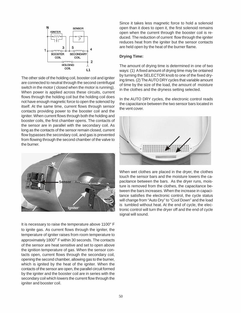
50
Since it takes less magnetic force to hold a solenoidopen than it does to open it, the first solenoid remainsopen when the current through the booster coil is re-duced. The reduction of current flow through the igniterreduces heat from the igniter but the sensor contactsare held open by the heat of the burner flame.
Drying Time:
The amount of drying time is determined in one of twoways: (1) A fixed amount of drying time may be ontainedby turning the SELECTOR knob to one of the fixed dry-ing times. (2) The AUTO DRY cycles that variable amountof time by the size of the load, the amount of moisturein the clothes and the dryness setting selected.
In the AUTO DRY cycles, the electronic control readsthe capacitance between the two sensor bars located inthe vent cover.
When wet clothes are placed in the dryer, the clothestouch the sensor bars and the moisture lowers the ca-pacitance between the bars. As the dryer runs, mois-ture is removed from the clothes, the capacitance be-tween the bars increases. When the increase in capaci-tance satisfies the electronic control, the cycle statuswill change from “Auto Dry” to “Cool Down” and the loadis tumbled without heat. At the end of cycle, the elec-tronic control will turn the dryer off and the end of cyclesignal will sound.
L1
N
The other side of the holding coil, booster coil and igniterare connected to neutral through the second centrifugalswitch in the motor ( closed when the motor is running).When power is applied across these circuits, currentflows through the holding coil but the holding coil doesnot have enough magnetic force to open the solenoid byitself. At the same time, current flows through sensorcontacts providing power to the booster coil and theigniter. When current flows through both the holding andbooster coils, the first chamber opens. The contacts ofthe sensor are in parallel with the secondary coil. Aslong as the contacts of the sensor remain closed, currentflow bypasses the secondary coil, and gas is preventedfrom flowing through the second chamber of the valve tothe burner.
It is necessary to raise the temperature above 1100° Fto ignite gas. As current flows through the igniter, thetemperature of igniter raises from room temperature toapproximately 1800° F within 30 seconds. The contactsof the sensor are heat sensitive and set to open abovethe ignition temperature of gas. When the sensor con-tacts open, current flows through the secondary coil,opening the second chamber, allowing gas to the burner,which is ignited by the heat of the igniter. When thecontacts of the sensor are open, the parallel circuit formedby the igniter and the booster coil are in series with thesecondary coil which lowers the current flow through theigniter and booster coil.
Igniter
Sensor

51
SECTION F - TROUBLESHOOTING
Model Differences:• Better models have a digital display.• Good models do not have a digital display.
Failure Codes
The electronic controls of the dryer have self diagnosticscodes built in that cover most products failures.
On Better models, the error codes will appear in thedigital display as an E followed by either two numbers, anumber and a letter or two letters. The control will beepand the STATUS indicator lights will flash. To stop theflashing and beeping, touch the Pause Cancel button.The error code remains stored in the control.
On Good models, the STATUS indicator lights will flashthe number of times for the first digit after the E and theSTART indicator light will flash the number of times forthe second digit after the E. When a failure occurs, thedryer stops or pauses. The control will beep and flashthe STATUS lights to tell the customer that a failure hasoccurred. To stop the flashing and beeping, touch thePause Cancel button. The error code remains stored inthe control.
To view the error codes:
Better Models:1. Rotate the CYCLE SELECT KNOB clockwise (3)
setting from the Normal cycle option.
2. Press and hold the Select and Pause Cancel buttonssimultaneously for (6) seconds.
3. Immediately after, press and hold the START andPause Cancel buttons simultaneously for (4)seconds.
4. Rotate the CYCLE SELECT KNOB (1) clickcounterclockwise.
The error code will appear in the display. Troubleshootthe problem by using the chart on the next page.To move to the next code, press the OPTIONS button.To clear code, press the Select botton.To exit this mode, simultaneously press and hold theSelect and Pause Cancel buttons for (6) seconds toreset.NOTE: During normal operation, the display may show:
“ad” - dryer is in an auto dry cycle.“dn” - cycle is done in auto dry.“Err” - an error has been detected.“LOC” - control lock is activated.“PAU” - cycle has been interrupted.
Good Models:1. Rotate the CYCLE SELECT KNOB to the 3 O’clock
position.
2. Press and hold the Select and Pause Cancelbuttons simultaneously for (6) seconds.
3. Immediately after, press and hold the START andPause Cancel buttons simultaneously for (4)seconds.
4. Rotate the CYCLE SELECT KNOB to the 2 O’clockposition.
The STATUS indicator lights will flash the number oftimes for the first digit of the code and the START indicatorlight will flash the number of times for the second digit.The code is obtained by counting the number of timesthe lights flash. Example E24: the STATUS indicatorlights would flash twice indicating the 2 and the STARTindicator light will flash four times indicating the 4. TheSTATUS indicator lights and the START indicator lightwill start flashing at the same time. The control will thenpause for 2 seconds, then repeat the code.Troubleshoot the problem by using the chart on nextpage.
To move to the next code, press the OPTIONS button.To clear code, press the Select botton.To exit this mode, simultaneously press and hold theSelect and Pause Cancel buttons for (6) seconds toreset.
Better & Good Models:Note: A letter appearing in the code stands for a
number higher than nine.
A = 10B = 11C = 12D = 13E = 14F = 15
Example Code E4A: the first digit would be 4 and thesecond digit would be 10. If this code would appear on awasher in the Good model line, the STATUS indicatorlights would blink four times and the START indicatorlight would blink ten times.

52
Error code chart
Error code Fault condition Action
E 10 Communication failure. Clear code, exit mode and start dryer. If theerror persists, replace the control board.
E 11 Communication failure. Clear code, exit mode and start dryer. If theerror persists, replace the control board.
E 12 Communication failure. Clear code, exit mode and start dryer. If theerror persists, replace the control board.
E 24 Shorted control thermistor. Remove wires from the control thermistor.Measure resistance of the thermistor. If thereading is not 50K (+/- 10 %), replace thermistor.If the reading is within 50K (+/-10%) checkwiring between thermistor and electroniccontrol. If good, replace eclectronic control.
E 25 Open control thermistor. Remove wires from the control thermistor.Measure resistance of the thermistor. If thereading is not 50K (+/- 10 %), replace thermistor.If the reading is within 50K (+/-10%) checkwiring between thermistor and electroniccontrol. If good, replace eclectronic control.
E4A The drying time has exceeded program Press Pause Cancel and SELECT buttons fortime for that cycle. 6 seconds to exit test modes. Position cycle
selector to NORMAL, temperature selector toHIGH HEAT and touch START. Check for anything that would extend dry times such as: noheat, restricted vent, blower fan blade brokenor loose, dryer installed in closet with solid door,or bad connection in moisture sensor bar circuit or dirty bars. If dryer operates normally butcode returns, replace electronic control.
E 5B No heat. Refer to flow chart dryer does not heat.
E 68 One of the keys (buttons) is Enter function test mode and perform keystuck closed (active). (button) test to determine which button is at
fault. Carefully free the and perform the testagain. If button is free but the key struck codestill exists, replace electronic control.
E 8C High limit thermostat has trip to many times Check for blocked lint filter, blocked exhaust,in a certain amount of time. air leaks around air duct, broken blower fan
blades, worn or loose drum seals, dryer installedin closet with solid doors or door seal notcorrectly seated.
E AF Microcontroller has been reset Clear code, exit mode and start dryer. Ifby internal Watchdog timer. problem persists, replace electronic control.

53
TROUBLESHOOTING FLOW CHARTS
NOTE: Always check the wiring and pin/plug connectors before replacing any component.
NOTE: If a fault code is displayed the dryer will not operate. Refer to page 8 for information on fault codes.
Electric dryer completely inoperative. 54
Gas dryer completely inoperative. 55
Electric and Gas dryers; blower motor runs but drum does not turn. 56
Electric and Gas dryers; longer than normal drying times. 56
Electric dryer not heating properly. 57
Gas dryer not heating properly. 58
Electric and Gas dryers; dryer over heating. 58
Electric dryers; blower motor runs but dryer does not heat. 59
Gas dryers; blower motor runs but dryer does not heat. 60
Electric and Gas dryers; clothes not dry in auto cycle. 61

54
Dryer completelyinoperative.
Does the control beep orthe LED flash when thestart button is pushed.?No.
Defective householdpower supply or
broken wire betweendryer terminal blockand thermal limiter.
Electric dryer completely inoperative.Note: Always check wiring to the components.Note: If a fault code is displayed the dryer will not operate.
0.
Measure the voltage dropbetween the red wire on thethermal limiter and neutral.
Yes.
Measure the voltage dropbetween the orange wire on
the thermal limiter andneutral.
120VAC.
Defective thermallimiter.
0.
Measure the voltage dropbetween pins 1 & 2 of theeight pin plug of the wireharness to the control
board.
120VAC.
Broken wire betweenthermal limiter andthe control board.
0. 120VAC.
Defective controlboard.
Is an errorcode display.
Refer to errorcode chart.
Yes.
Measure the voltage dropbetween pins 1 & 2 of J-4
120VAC.
Defective controlboard.
Defective doorswitch.
0.
No.

55
Gas dryer completely inoperative.Note: Always check wiring to the components.Note: If a fault code is displayed the dryer will not operate.
Dryer completelyinoperative.
Does the control beep orthe LED flash when thestart button is pushed.?
No.
Defective householdpower supply or
broken wire betweendryer terminal blockand thermal limiter.
Yes.
Measure the voltage dropbetween pins 1 & 2 of theeight pin plug of the wireharness to the control
board.
0. 120VAC.
Defective controlboard.
Is an errorcode display.
No.Refer to errorcode chart.
Yes.
Measure the voltage dropbetween pins 1 & 2 of J-4
120VAC.
Defective controlboard.
Defective doorswitch.
0.

56
Drive motor runs butdrum does not turn.
Electric and Gas dryers; blower motor runs but drum does not turn.Note: Always check wiring to the components.
Belt broken oroff pulley.
Longer than normaldrying times.
Electric and Gas dryers; longer than normal drying times. (Possible E 4A)Note: Always check wiring to the components.
Check washerspin cycle.
Are the clothes wetter than normalwhen removed from the washer?
Yes.
Clear vent.
Is the vent restricted?Yes.
No.
No.
Refer to dryer notheating properly
flow chart.
Is the dryer heating properly?
Review properprogramming ofthe control withthe customer.
Yes.
Is the dryer level so the clothestouch the sensor bars?
Yes.Level dryer.
No.
Is the blower motor runningat full speed?
No.
Yes.Replace motor.
No.

57
Electric dryer not heatingproperly.
Electric dryers not heating properly (Possible E 5b)Note: Always check wiring to the components.
Program the dryer for a NormalCycle with High Temp and touchStart. Measure the voltage drop
between L1 and L2 at the terminalblock.Below 215 VAC.
Have customercheck house wiring.
Measure the voltage dropbetween two terminals of the
heating element.Not the same asbetween L1 & L2.
Above 215 VAC.
Check for poorconnections in the
dryer heating circuit.
Check the resistance of thecontrol thermistor at room
temperature.
50000 Ohms +/- 10%.
Defective electroniccontrol.
Defectivethermistor.
More or less than50000 Ohms +/- 10%.
The same asbetween L1 & L2.
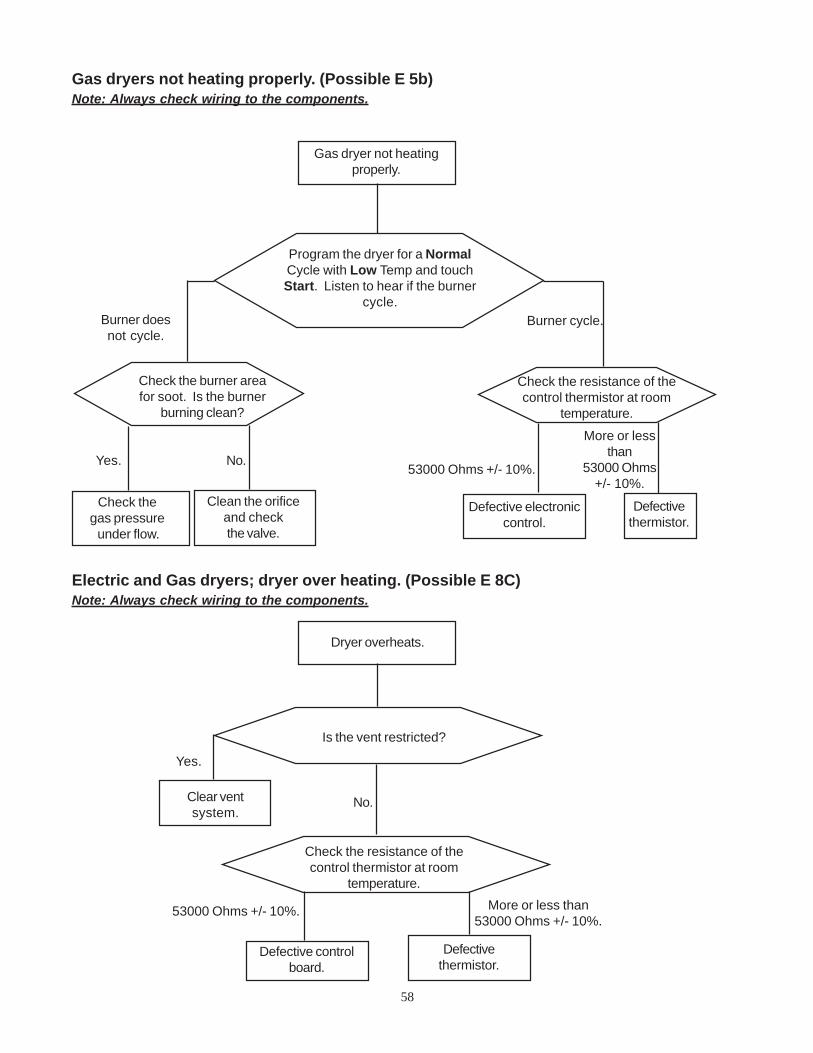
58
Gas dryer not heatingproperly.
Gas dryers not heating properly. (Possible E 5b)Note: Always check wiring to the components.
Check the burner areafor soot. Is the burner
burning clean?
No.
Check thegas pressure under flow.
Check the resistance of thecontrol thermistor at room
temperature.
53000 Ohms +/- 10%.
Defective electroniccontrol.
Defectivethermistor.
More or lessthan
53000 Ohms+/- 10%.
Program the dryer for a NormalCycle with Low Temp and touchStart. Listen to hear if the burner
cycle.
Yes.
Clean the orificeand checkthe valve.
Burner doesnot cycle.
Burner cycle.
Dryer overheats.
Electric and Gas dryers; dryer over heating. (Possible E 8C)Note: Always check wiring to the components.
Is the vent restricted?
Clear ventsystem.
Yes.
No.
Check the resistance of thecontrol thermistor at room
temperature.
53000 Ohms +/- 10%.
Defective controlboard.
Defectivethermistor.
More or less than53000 Ohms +/- 10%.

59
Electric dryers; drive motor runs but dryer does not heat.Note: Always check wiring to the components.
Drive motor runs butdryer does not heat.
Program the dryer for a NormalCycle with High Temp and touchStart. Measure the voltage drop
between the two terminals of RL 2.
Defective electroniccontrol board.
Measure the voltage drop be-tween the two terminals of the
high limit thermostat.
0.Defective highlimit thermostat.
Remove power from the dryer anddisconnect the black wire from RL 2.Restart the dryer and measure thevoltage drop between red wire on
RL 2 and neutral0.
120 VAC.
Open wire fromterminal block.
0.120 VAC.
Defective motor. Defectiveheating element.
240 VAC.
0.
240 VAC.
Remove power from the dryer,reconnect the black wire from RL 2.
and disconnect the plug from thedrive motor. Restart the dryer andmeasure the voltage drop betweenyellow and white wire in the plug.
Check the resistance of thecontrol thermistor at room
temperature.
50000 Ohms +/- 10%. Defectivethermistor.
More or less than50000 Ohms +/- 10%.

60
Drive motor runs butdryer does not heat.
Gas dryers; drive motor runs but dryer does not heat.Note: Always check wiring to the components.
Remove power, turn the gas offto the dryer, disconnect the belt from the
motor, and remove the front panel. Programthe control for Normal Cycle High Temp
and observe the igniter for 1 minute.
Igniter glows fullbrilliance or glows dim the
full minute.
Igniter doesnot glow.
Defectivesensor.
Igniter glows fullbrilliance then dims.
Defectivegas valveor gas supply.
Program the dryer for a NormalCycle with High Temp and touchStart. Measure the voltage drop
between the two terminals of RL 2.
Defective electroniccontrol board.
120 VAC.
0.
120 VAC.
Remove power, unplug theigniter and measure the resistance
of the igniter.
Measure the voltage drop from theterminal on the sensor with the
orange wire to neutral.0.
Defective highlimit thermostat.
Infinity. 50 to 400 OHMS.
Defective igniter. Defectivemotor.
Check the resistance of thecontrol thermistor at room
temperature.
50000 Ohms +/- 10%.Defective
thermistor.
More or less than50000 Ohms +/- 10%.

61
Electric and Gas dryers; clothes not dry in auto cycle.Note: Always check wiring to the components.
Clothes not dry in theauto cycle.
Check that the dryer islevel or slightly tip
forward.
Using the on function test do the 3O’clock test. (Refer to pages 8)
Tested good.
Tighten the con-nections or replace
the wire.
Replace theelectronic control.
Checks good.
Check the connections at the barsand the wiring between the control
and the bars.
Are the sensor bars clean?No.
Yes.Clean bars.
Failed test.
Checks bad.
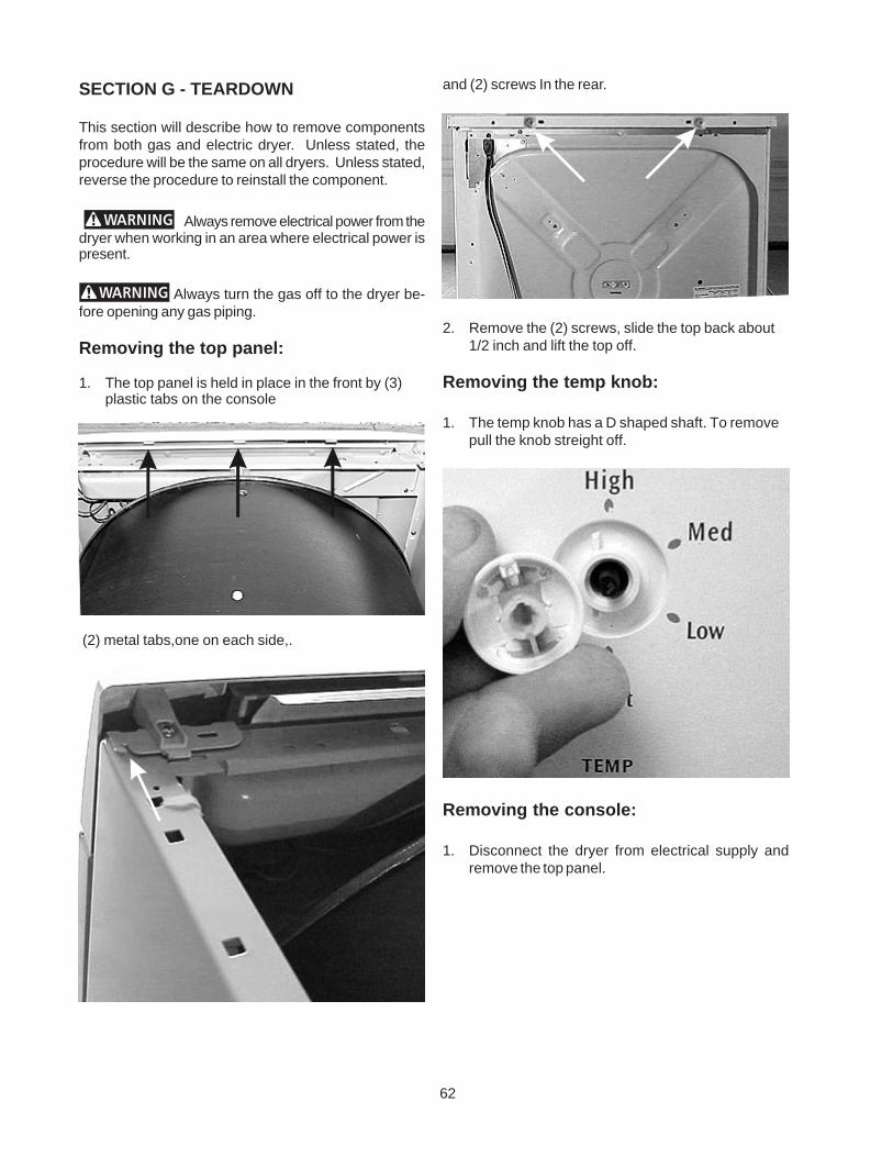
62
and (2) screws In the rear.
2. Remove the (2) screws, slide the top back about1/2 inch and lift the top off.
Removing the temp knob:
1. The temp knob has a D shaped shaft. To removepull the knob streight off.
Removing the console:
1. Disconnect the dryer from electrical supply andremove the top panel.
SECTION G - TEARDOWN
This section will describe how to remove componentsfrom both gas and electric dryer. Unless stated, theprocedure will be the same on all dryers. Unless stated,reverse the procedure to reinstall the component.
Always remove electrical power from thedryer when working in an area where electrical power ispresent.
Always turn the gas off to the dryer be-fore opening any gas piping.
Removing the top panel:
1. The top panel is held in place in the front by (3)plastic tabs on the console
(2) metal tabs,one on each side,.

63
2. Remove the (4) screws, (2) on each side, holding theconsole to the front panel and roll the consoleforward.
3. Disconnect the wiring from the control board and liftthe console off.
Removing the control board:
1. Disconnect the dryer from electrical supply, removetheTemp knob and the top panel.
2. Remove the console.
3. Remove the (5) screws holding the control board tothe console.
4. Release the (2) tabs at the bottom and the (3) tabsat the top and lift the control board out.
Note: Be careful not to lose the springs.
Removing the programing buttons andsprings:
1. Disconnect dryer from the electrical supply andremove the control board.
2. Lift the buttons and springs out of the console.
3. The buttons are not all the same. Each button hasa Roman numeral stamped into it and the consolehas Roman numeral above the button slot. Matchthe number on to button to the number on the slot.
Removing the temp knob shaft:
1. Disconnect dryer from the electrical supply, turn theTEMP konb to HOT and remove the knob.
2. Remove the control board.

64
2. Using pliers squeeze the lock rim of the knob shaftand pull the knob out the front.
Removing the loading door:
1. Open the door and while supporting the door removethe (4) screws, (2) from each hinge, holding the doorto the hinges.
Disassembling the loading door:
1. Remove the door from the dryer.
3. Lift the shaft out of the control.
Removing the selector knob shaft:
1. Disconnect dryer from the electrical supply, turn theSELECTOR knob to 12 O’clock and remove thecontrol board.
2. Lift the shaft out of the control.
Removing the selector knob:
1. Disconnect dryer from the electrical supply andremove the control board.

65
2. Separate the panels on the hinge and slide the innerpanel out from behind the flange of the outer panel.
Removing the door handle:
1. Separate the panel and lift the handle off the innerdoor liner.
Removing the upper or lower door strike:
1. Separate the panel, squeeze the ends of the strikeand push it through the inner panel.
Removing the door seal:
1. The door seal is fasten to the inner door liner byexpandable tabs pushed through slots in the liner.
2. If the seal is to be replaced open the door and pullthe seal from the liner. If the seal is to be reused,separate the panels and use a small screwdriver topush the tabs through the liner.
Removing the front access panel:
1. Place a 2 by 4 under the front of the dryer and removethe two screws holding the panel to the dryer base.
Removing the door switch:
1. Disconnect the dryer from electrical supply, openthe door and remove the top.
2. Disconnect the wires from the door switch.

66
3. Squeeze the release tabs on the ends of the switchand push it out the front.
Removing the front panel:
1. Disconnect the dryer from electrical supply, removethe console and front access panel.
2. Remove the (2) screws, one on each side, at thebottom holding the front panel to the bodysides.
3. Remove the (2) screw, one on each side about (8)inches down from the top, that holds the front panelto the bodysides.
4. Pull out on the bottom of the front panel to releasethe spring load tabs.
5. Lift up on the front panel to relase the (2) tabs at thetop, one on each end, and swing the panel out.
6. Disconnect the wiring from the drum light, doorswitch, the ground wire, and unplug the wiringharness from the sensor bars.

67
Replacing the upper door catch:
1. Disconnect the dryer from electrical supply andremove the front panel.
2. Using a common screwdriver release the spring clipfrom the backcatch and push the catach out thefront.
Replacing the lower door catch:
1. Disconnect the dryer from electrical supply, removethe front panel and the front panel air duct.
2. Using a common screwdriver release the spring clipfrom the backcatch and push the catach out thefront.
Replacing the sensor bars:
1. Disconnect the dryer from electrical supply.
2. Open the dryer door and remove the lint screen.
3. Remove the (2) screws holding the vent grill to thefront panel.
4. Pull the grill into the drum and disconnect the wires.
Replacing the front panel air duct:
1. Disconnect the dryer from electrical supply andremove the front panel.
2. Remove the (2) screws holding the vent grill to thefront panel.
3. Release the sensor wire harness and pull down toremove the air duct.

68
2. Remove the top and disconnect the wires from thelight socket.
3. Remove the light bulb, squeeze the tabs on the sideof the socket and push the socket into the housing.
Replacing the felt seal:
1. Disconnect the dryer from electrical supply.
2. Remove the front panel.
3. The felt seal is a (2) piece seal that is glued to frontpanel rim that the drum rides on.
4. To replace the seal pull the seal off and glue thereplacement to the rim.
Replacing the drum light bulb:
1. Open the dryer door, release the clip holding thelight shield by pushing up, and unscrew the bulb.
Replacing the drum light housing:
1. Disconnect the dryer from electrical supply.
2. Remove the top, lean the top of the front panelforward and disconnect the wires from the lightsocket.
3. Push in to release the tab at the end of the housingand push the housing into the drum.
Replacing the drum light socket:
1. Disconnect the dryer from electrical supply.

69
Removing the vane from the drum:
1. Disconnect the dryer from electrical supply.
2. Open the door, remove the top panel, remove the (2)screws holding the vane to the drum and drop thevane into the drum.
Removing the drum:
1. Disconnect the dryer from electrical supply.
2. Remove the top and the front panels.
3. Release the belt from the motor.
Replacing the foam seal:
1. Disconnect the dryer from electrical supply.
2. Remove the front panel.
3. The foam seal is glued to front panel duct and sealsbetween the front panel duct and the blower.
4. To replace the seal pull the seal off and glue thereplacement to the duct.
Removing the rear access panel:
1. Remove the (2) screws holding the access panelto the rear panel and swing the left side of the ventout to disengage the tabs.
Releasing the dryer belt:
1. Remove the access panel.
2. Push the idler pulley to the right and slip the belt offthe motor pulley.

70
4. Use the belt to raise rear of the drum to release theball from the hitch and move the drum out the front.
Removing the belt:
1. Disconnect the dryer from electrical supply.
2. Remove the top and the front panels.
3. Release the belt from the motor.
4. From the front, slightly raise the front of the drum andslide the belt off.
Removing the ball hitch from the drum:
1. Disconnect the dryer from electrical supply andremove the drum.
2. Remove the (3) screws from inside the drum holdingthe ball to the drum.
Removing the teflon glides:
1. Disconnect the dryer from electrical supply andremove the front panel.
2. Squeeze the tabs to release the glides.

71
Removing the high limit thermostat:
1. Disconnect the dryer from electrical supply andremove the top panel.
2. Disconnect the (2) wires and remove the (2) screwsholding thermostat to the heating element assem-bly.
Removing the thermal limiter: (Electric dry-ers)
1. Disconnect the dryer from electrical supply andremove the top panel.
2. Disconnect the (2) wires and remove the two screwsholding limiter to the rear panel.
Removing the drum heat shield: (Electricdryers)
1. Disconnect the dryer from electrical supply andremove the drum.
2. Remove the (3) screws holding the shield to the rearof the drum.
Removing the hitch:
1. Disconnect the dryer from electrical supply andremove the drum.
2. Using a 5/16” nut driver remove the (2) screwsholding the hitch to the rear panel while holding thelarge tinnerman clip from the rear of the dryer.
Note: Do not lose the grounding ball or the tinnerman mounting clip from the rear of the dryer.

72
Removing the heating element assembly:(Electric dryers)
1. Disconnect the dryer from electrical supply andremove the drum.
2. Disconnect the (2) wires from the heating element.
3. Remove the high limit thermostat.
4. From the rear of the dryer remove the (4) screwssecuring the heating element assembly to the rearof the cabinet.
Removing the control thermistor:
1. Disconnect the dryer from electrical supply andremove the front panel.
2. Disconnect the wires from the thermistor and re-move the (2) screws holding the thermistor to theblower housing.
Removing the blower housing and fanblade:
1. Disconnect the dryer from electrical supply andremove the drum.
2. Remove the control thermistor.
3. Using a 7/8” socket turn the fan blade clockwisewhile holding the motor shaft to remove the bladefrom the motor shaft.

73
Removing the idler pulley:
1. Disconnect the dryer from electrical supply andremove the rear access panel.
2. Release the belt from the motor pulley and slide theidler pulley off.
Removing the idler pulley assembly:
1. Disconnect the dryer from electrical supply andremove the rear access panel.
2. Release the belt from the motor pulley.
3. Release the idler spring from the motor and lift theassembly off the motor.
Removing the drive motor:
1. Disconnect the dryer from electrical supply andremove the drum.
4. Remove (2) screws holding the housing to the dryerbase.
5. Remove the front motor lock by inserting a screw-driver at the rear of the housing to release thehousing from the motor.
6. Raise the front of the motor and pull the housingforward.
SpringHoldDown

74
Removing the ignitor: (Gas dryers)
1. Disconnect the dryer from electrical supply andunplug the igniter harness.
2. The igniter is held to the burner mounting bracket bya screw and a tab. Remove the screw and lift theigniter up to release the tab, then slide the igniterforward.
Removing the gas valve assembly: (Gasdryers)
1. Turn the gas supply off and disconnect the dryerfrom electrical supply.
2. Unplug the wires from the valves.
2. Unplug the harness from the motor and remove theidler assembly.
3. Unscrew the blower wheel from motor shaft.
4. Release the front motor lock from the blower hous-ing.
5. Release the spring hold down on the rear of the motorand lift the motor out.
Removing the burner: (Gas dryers)
1. Disconnect the dryer from electrical supply andremove the front panel.
2. Unplug the igniter, remove the (2) screws holdingthe burner to the valve assembly bracket, and slidethe burner into the combustion chamber to releaseburner from the valve.

75
Removing the gas valve coils: (Gas dryers)
1. Disconnect the dryer from electrical supply andremove the front panel.
2. Disconnect the wires from the coils, remove the(2) screws holding the coil bracket to the valvebase and lift the coils off.
Removing the sensor: (Gas dryers)
1. Disconnect the dryer from electrical supply andremove the front panel.
2. Disconnect the (2) wires from the sensor.
3. Remove the (1) screw holding the sensor to thecombustion chamber.
Removing the combustion chamber: (Gasdryers)
1. Disconnect the dryer from electrical supply,remove the sensor and gas valve assembly.
3. Using a 15/16” open end wrench, disconnectthe manifold pipe from the valve.
4. Remove the (1) screw securing the gas valveassembly bracket to the base, slide the gas valveassembly forward and lift the gas valve assemblyout.
5. Remove the (2) screws holding the valve to thebracket.

76
Removing the manifold pipe: (Gas dryers)
1. Disconnect the dryer from electrical supply.
2. Turn the gas supply off and disconnect the gassupply from the dryer.
3. Remove dryer front panel.
4. Using a 15/16” open end wrench disconnectmanifold pipe from the valve.
2. Remove the (2) screws holding the combustionchamber to the base, raise the end and pull thechamber out of the duct.
.
Removing the duct and heat shield: (Gasdryers)
1. Disconnect the dryer from electrical supply,remove the drum.
2. Remove (4) screws holding the heat shield to therear panel.
3. Lift the shield and duct out of the dryer and removethe (3) screws holding duct to the heat shield.

77
5. Remove the (2) screws holding the manifold pipeto the base and lift the pipe out.
Removing the vent pipe: (Gas dryers)
1. Remove the (1) screw holding vent to the rearpanel and pull the vent pipe out the back.
Removing the gasket between the ventpipe and blower housing : (Gas dryers)
1. Disconnect the dryer from electrical supply.
2. Remove front panel and slide the gasketcompletely on to the vent pipe.
3. Remove the vent pipe out the rear of the dryer andremove the gasket from the vent pipe.
4. When reinstalling, install the gasket on the ventpipe, install the vent pipe in the dryer and slide halfof the gasket on to the blower housing from thefront of the dryer.
78
NOTES

79
NOTES

80