5ea-28199-e2 xjr1300spxjr1300 owner’s … owner’s manual does not only instruct you in how to...
TRANSCRIPT

5EA-28199-E2
XJR1300XJR1300SP
OWNER’S MANUAL

00001 INTRODUCTION
benefiting from Yamaha’s vast and the manufacture of high-tion for dependability.
o as to enjoy all your XJR1300/ not only instruct you in how toso in how to safeguard yourself
elp to keep your motorcycle inestions, do not hesitate to con-
nt rides. So, remember to put
EAU
Welcome to the Yamaha world of motorcycling!
As the owner of a XJR1300/XJR1300SP, you are experience in and newest technology for the designquality products, which have earned Yamaha a reputa
Please take the time to read this manual thoroughly, sXJR1300SP’s advantages. The owner’s manual doesoperate, inspect and maintain your motorcycle, but aland others from trouble and injury.
In addition, the many tips given in this manual will hthe best possible condition. If you have any further qutact your Yamaha dealer.
The Yamaha team wishes you many safe and pleasasafety first!

EAU00005PORTANT MANUAL INFORMATION
ticularly important information is distinguished in this manual by the following notations:
ERT! YOUR SAFETY IS
IM
Par
re injury or death to theing the motorcycle.
to avoid damage to the
learer.
torcycle and should remain
d quality. Therefore, whilelable at the time of printing, this manual. If there is anydealer.
C
N
The Safety Alert Symbol meaINVOLVED!
WARNING Failure to follow WARNING imotorcycle operator, a bystand
AUTION: A CAUTION indicates specialmotorcycle.
OTE: A NOTE provides key informati
NOTE:@
● This manual should be considwith it even if the motorcycle
● Yamaha continually seeks adthis manual contains the mosthere may be minor discrepanquestion concerning this man
@
ns ATTENTION! BECOME AL
nstructions could result in seveer or a person inspecting or repair
precautions that must be taken
on to make procedures easier or c
ered a permanent part of this mois subsequently sold.vancements in product design ant current product information avaicies between your motorcycle andual, please consult your Yamaha

IMPORTANT MANUAL INFORMATIONEW000002
INGAD THIS MANUAL CAREFULLY AND COMPLETELY BEFORE OPERATINGRCYCLE.
WARN@
PLEASE RETHIS MOTO@

IMPORTANT MANUAL INFORMATION
© 199
All rightunauthopermissi
i
EAU00008
XJR1300/XJR1300SPOWNER’S MANUAL
9 by Yamaha Motor Co., Ltd.1st Edition, July 1999
s reserved. Any reprinting orrized use without the writtenon of Yamaha Motor Co., Ltd.s expressly prohibited.
Printed in Japan.
TABLE OF CONTENTS
RIGHT OF WAY 1
2
CONTROL FUNCTIONS 3
HECKS 4
PORTANT RIDING POINTS 5
NANCE AND MINOR REPAIR 6
E AND STORAGE 7
8
MATION 9
EAU00009
1 GIVE SAFETY THE
2 DESCRIPTION
3 INSTRUMENT AND
4 PRE-OPERATION C
5 OPERATION AND IM
6 PERIODIC MAINTE
7 MOTORCYCLE CAR
8 SPECIFICATIONS
9 CONSUMER INFOR
INDEX

1
GIVE SAFETY THE RIGHT OF WAY
GIVE SAFETY THE RIGHT OF WAY................................................. 1-1
1
EAU00021
nsurpassed feeling of power andt accept; even the best motorcycle
motorcycle’s value and operatinge for the rider: good performanceedication, drugs and alcohol is, ofrs - must always be at their mentallcohol, there is a tendency to take
eat belts are for car drivers and made of leather or tear-resistantves and a properly fitting helmet.relessness. Though full-coverage and protection, motorcyclists willrisk of going too fast and are apt tohe good motorcyclist rides safely, caused by others.
1-1
1-GIVE SAFETY THE RIGHT OF WAY
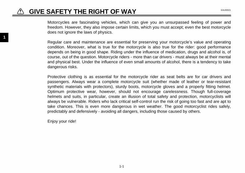
Motorcycles are fascinating vehicles, which can give you an ufreedom. However, they also impose certain limits, which you musdoes not ignore the laws of physics.
Regular care and maintenance are essential for preserving yourcondition. Moreover, what is true for the motorcycle is also trudepends on being in good shape. Riding under the influence of mcourse, out of the question. Motorcycle riders - more than car driveand physical best. Under the influence of even small amounts of adangerous risks.
Protective clothing is as essential for the motorcycle rider as spassengers. Always wear a complete motorcycle suit (whethersynthetic materials with protectors), sturdy boots, motorcycle gloOptimum protective wear, however, should not encourage cahelmets and suits, in particular, create an illusion of total safetyalways be vulnerable. Riders who lack critical self-control run the take chances. This is even more dangerous in wet weather. Tpredictably and defensively - avoiding all dangers, including those
Enjoy your ride!
Give safety the right of way

2
DESCRIPTION
Left view ............................................................................................. 2-1Right view........................................................................................... 2-2Controls/Instruments .......................................................................... 2-3

2
EAU00026
2-DE
Lef
)
1.2.3.4.5.6.7.
2-1
SCRIPTION
t view
Clutch fluid reservoir (page 6-18)Fuel cock (page 3-10)Rear shock absorber spring preload adjusting ring (page 3-13)Luggage strap holders (page 3-15)Helmet holder/seat lock (page 3-12 / page 3-11Shift pedal (page 3-7)Engine oil filter element (page 6-8)

DESCRIPTION
2
R
89
101112
(page 6-10)(page 3-9)
ervoir (page 6-18)(page 6-25)(page 3-8)
2-2
ight view
. Tail/brake light (page 6-27)
. Luggage strap holders (page 3-15)
. Tool kit (page 6-1)
. Rear brake fluid reservoir (page 6-18)
. Fuses (page 6-25)
13. Air filter14. Fuel tank15. Front brake fluid res16. Headlight17. Rear brake pedal

DE
2
Co
1.2.3.4.5.6.
ches (page 3-6)(page 3-8)(page 6-12)
lock (page 3-1)load
(page 3-13)
SCRIPTION
2-3
ntrols/Instruments
Clutch lever (page 3-7)Left handlebar switches (page 3-5)Starter (choke) “ ” (page 3-11)Speedometer (page 3-4)Fuel gauge (page 3-5)Tachometer (page 3-4)
7. Right handlebar swit8. Front brake lever9. Throttle grip
10. Main switch/steering11. Front fork spring pre
adjusting bolt

3
INSTRUMENT AND CONTROL FUNCTIONS
Main switch/steering lock......................................3-1Indicator lights ......................................................3-2Oil level indicator circuit check..............................3-3Speedometer ........................................................3-4Tachometer ...........................................................3-4Antitheft alarm (optional) ......................................3-4Fuel gauge............................................................3-5Handlebar switches ..............................................3-5Clutch lever ...........................................................3-7Shift pedal.............................................................3-7Front brake lever ...................................................3-8Rear brake pedal ..................................................3-8
Fuel tank cap ....................................................... 3-9Fuel ...................................................................... 3-9Fuel cock............................................................ 3-10Starter (choke) “ ”........................................... 3-11Seat.................................................................... 3-11Helmet holder..................................................... 3-12Storage compartment ........................................ 3-12Front fork adjustment ......................................... 3-13Rear shock absorber adjustment ....................... 3-13Luggage strap holders ....................................... 3-15Sidestand ........................................................... 3-15Sidestand/clutch switch operation check............ 3-15

3
EAU00027
3-IN
EW000016
WARNINGer turn the key to “OFF” orCK” when the motorcycle isving. The electrical circuits willswitched off which may result in of control or an accident. Be
e the motorcycle is stopped be- turning the key to “OFF” orCK”.
ushurn
MaTheanddes
ONEleengbe r
OFAll Thetion
3-1
STRUMENT AND CONTROL FUNCTIONS
EAU00029*
in switch/steering lock main switch controls the ignition lighting systems. Its operation iscribed below.
EAU00036
ctrical circuits are switched on. Theine can be started. The key cannotemoved in this position.
EAU00038
Felectrical circuits are switched off. key can be removed in this posi-.
EAU00040
LOCKThe steering is locked in this positionand all electrical circuits are switchedoff. The key can be removed in this po-sition.To lock the steering, turn the handle-bars all the way to the left. While push-ing the key into the main switch, turn itfrom “OFF” to “LOCK” and remove it.To release the lock, turn the key to“OFF” while pushing.
@
Nev“LOmobe losssurfore“LO@
1. P2. T

NTROL FUNCTIONS
3
ThanoncaTothDeddi
EAU00061
utral indicator light “ ”is indicator comes on when thensmission is in neutral.
EAU01313
il level indicator light “ ”is indicator comes on when the oilel is low. This light circuit can beecked by the procedure on page 3-3.
EC000000
AUTION: not run the motorcycle until youow it has sufficient engine oil.
TE:en if the oil is filled to the specifiedel, the indicator light may flickeren riding on a slope or during sud-n acceleration or deceleration, but
is is normal.
INSTRUMENT AND CO
3-2
EAU01590
(Parking)e steering is locked in this position,d the taillight and auxiliary light come but all other circuits are off. The keyn be removed in this position. use the parking position, first lock
e steering, then turn the key to “ ”.o not use this position for an extend- length of time as the battery may
scharge.
EAU00056
Indicator lightsEAU00058
Turn indicator lights “ ” / “ ”The corresponding indicator flasheswhen the turn switch is moved to theleft or right.
EAU00063
High beam indicator light “ ”This indicator comes on when theheadlight high beam is used.
NeThtra
OThlevch
C@
Dokn@
NO@
Evlevwhdeth@
1. Left turn indicator light “ ”2. High beam indicator light “ ”3. Neutral indicator light “ ”4. Right turn indicator light “ ”5. Oil level indicator light “ ”

IN
3
EAU00073
CB-52
dicator light n.
gine oil level.
Supply engine oil.
Oil level is low.
is turned on, the oil level indicatorew seconds and then go off. If theome on, ask a Yamaha dealer to in-it.
STRUMENT AND CONTROL FUNCTIONS
3-3
Oil level indicator circuit checkE
Wait a few seconds (see NOTE).
Oil level indicator light goes off.
Oil level inremains o
Check en
Oil level indicator light comes on.
Oil level indicator light still does not come on.
Engine oil level and electrical circuit are OK. Go ahead with riding.
Put the transmission in neutral or apply the clutch lever, then push the start switch.
Oil level is OK.
Ask a Yamaha dealer to inspect electrical circuit.
Turn the main switch to “ON”.Turn the engine stop switch to “ ”.
NOTE:When the main switch light will come on for a findicator light does not cspect the electrical circu
NTROL FUNCTIONS
3
SThThododrewyofost
EAU00109
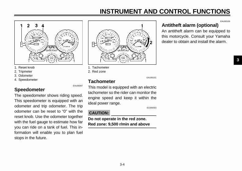
ntitheft alarm (optional) antitheft alarm can be equipped to
is motorcycle. Consult your Yamahaaler to obtain and install the alarm.
1.2.3.4.
INSTRUMENT AND CO
3-4
EAU00097
peedometere speedometer shows riding speed.is speedometer is equipped with anometer and trip odometer. The tripometer can be reset to “0” with theset knob. Use the odometer togetherith the fuel gauge to estimate how faru can ride on a tank of fuel. This in-rmation will enable you to plan fuelops in the future.
EAU00101
TachometerThis model is equipped with an electrictachometer so the rider can monitor theengine speed and keep it within theideal power range.
EC000003
CAUTION:@
Do not operate in the red zone.Red zone: 9,500 r/min and above @
AAnthde
Reset knobTripmeterOdometerSpeedometer
1. Tachometer2. Red zone

IN
3
FuThifuefuenee4.5
EAU00127
n signal switchsignal a right-hand turn, push thetch to “ ”. To signal a left-hand, push the switch to “ ”. Once thetch is released it will return to theter position. To cancel the signal,h the switch in after it has returnedhe center position.
EAU00129
n switch “ ”ss the switch to sound the horn.
1. F
STRUMENT AND CONTROL FUNCTIONS
3-5
EAU00110
el gauges model is equipped with an electricl gauge so the rider can monitor thel level in the fuel tank. When thedle indicates “E” (Empty), aboutL remain in the fuel tank.
EAU00118
Handlebar switchesEAU00120
Pass switch “PASS”Press the switch to operate the passinglight.
EAU00121
Dimmer switchTurn the switch to “ ” for the highbeam and to “ ” for the low beam.
TurTo switurnswicenpusto t
HorPre
uel gauge 1. Pass switch “PASS”2. Dimmer switch3. Turn signal switch4. Horn switch “ ”

NTROL FUNCTIONS
3
EnThviwtroTugisw
LiTuonta“
1.2.3.
INSTRUMENT AND CO
3-6
EAU00138
gine stop switche engine stop switch is a safety de-
ce for use in an emergency such ashen the motorcycle overturns or ifuble occurs in the throttle system.rn the switch to “ ” to start the en-
ne. In case of emergency, turn theitch to “ ” to stop the engine.
EAU00134
ghts switchrning the light switch to “ ”, turns the auxiliary light, meter lights and
illight. Turning the light switch to” turns the headlight on also.
EAU00143
Start switch “ ”The starter motor cranks the enginewhen pushing the start switch.
EC000005
CAUTION:@
See starting instructions prior tostarting the engine. @
Engine stop switchLights switchStart switch “ ”

IN
3
CluThehanlevwhcuistathisTo levtheshoslo
EAU00157
ift pedals motorcycle is equipped with a con-nt-mesh 5-speed transmission. shift pedal is located on the left of the engine and is used in com-
ation with the clutch when shifting.
1. C hift pedal
STRUMENT AND CONTROL FUNCTIONS
3-7
EAU00153
tch lever clutch lever is located on the leftdlebar. It is equipped with a clutch
er adjusting dial and a clutch switch,ich is integrated into the ignition cir-t cut-off system. (Refer to the enginerting procedures for a description of system.) disengage the clutch, pull the clutcher toward the handlebar. To engage clutch, release the lever. The leveruld be pulled rapidly and released
wly for smooth clutch operation.
To adjust the distance between theclutch lever and the handlebar grip,turn the clutch adjusting dial whilepushing the lever forward. Make surethe setting on the clutch lever adjustingdial is aligned with the arrow mark.
ShThistaThesidebin
lutch lever 1. Adjusting dial2. Arrow mark
1. S

NTROL FUNCTIONS
3
FThrigbrthth
EAU00162
ear brake pedale rear brake pedal is on the righte of the motorcycle. Press down on
e brake pedal to apply the rear brake.
1. Rear brake pedal
INSTRUMENT AND CO
3-8
EAU00161
ront brake levere front brake lever is located on theht handlebar and is equipped with aake lever adjusting dial. To activatee front brake, pull the lever towarde handlebar.
To adjust the front brake lever position,turn the brake lever adjusting dial whilepulling the lever forward. Make sure thesetting on the brake lever adjusting dialis aligned with the arrow mark.
RThsidth
Front brake lever 1. Arrow mark2. Adjusting dial
1.

IN
3
FuTo Opturnbe ope
To Pukeycoution
EAU01183
elke sure there is sufficient fuel in thek. Fill the fuel tank to the bottom of filler tube as shown in the illustra-.
EW000130
WARNINGnot overfill the fuel tank. Avoidling fuel on the hot engine. Do fill the fuel tank above the bot- of the filler tube or it may over- when the fuel heats up later andands.
1. L2. O
iller tubeuel level
STRUMENT AND CONTROL FUNCTIONS
3-9
EAU02935
el tank capopenen the lock cover. Insert the key and it 1/4 turn clockwise. The lock willreleased and the cap can bened.
closesh the tank cap into position with the inserted. To remove the key, turn itnterclockwise to the original posi-. Then, close the lock cover.
NOTE:@
This tank cap cannot be closed unlessthe key is in the lock. The key cannotbe removed if the cap is not lockedproperly. @
EW000023
WARNING@
Be sure the cap is properly installedand locked in place before riding themotorcycle. @
FuMatanthetion
@
Do spilnottomflowexp@
ock coverpen
1. F2. F

NTROL FUNCTIONS
3
C@
AlatFues@
N@
If feta@
Sis stands for “reserve”. If you are
nning out of fuel while riding with theel cock in the “ON” position, quicklyrn the lever to this position. Other-se the engine may die and will have be primed (see “PRI” below). Afterrning the lever to “RES”, fill the tank the first opportunity and be sure tot the fuel cock back to “ON”!
Arrow mark positioned over “RES”
ES: reserve position
INSTRUMENT AND CO
3-10
EAU00185
AUTION:ways wipe off spilled fuel immedi-ely with a dry and clean soft cloth.el may deteriorate painted surfac- or plastic parts.
EAU00191
OTE:knocking or pinging occurs, use a dif-rent brand of gasoline or higher oc-ne grade.
EAU00207
Fuel cockThe fuel cock supplies fuel from thetank to the carburetors while also filter-ing it.The fuel cock has three positions,which should be set as illustrated.
ONWith the fuel cock in this position, fuelflows to the carburetors when the en-gine is running. Set the fuel cock to thisposition when starting the engine andfor riding.
REThrufutuwitotuatse
Recommended fuel:Regular unleaded gasoline with a research octane number of 91 or higher.
Fuel tank capacity:Total:
21 LReserve:
4.5 L
1. Arrow mark positioned over “ON”
ON: normal position
1.
R

IN
3
PRThihasthefuemato t“REter
EAU01721
atremoveert the key in the helmet holder lock turn it as shown.
1. A
PR
pen
STRUMENT AND CONTROL FUNCTIONS
3-11
Is stands for “prime”. If the engine been allowed to run out of fuel, turn lever to the “PRI” position to sendl directly to the carburetors. This willke starting easier. However, be sureurn the lever to the “ON” position (orS” if you have not refuelled yet) af-
the engine has started.
EAU02976
Starter (choke) “ ”Starting a cold engine requires a richerair-fuel mixture. A separate starter cir-cuit supplies this mixture.Move in direction a to turn on thestarter (choke).Move in direction b to turn off thestarter (choke).
SeTo Insand
rrow mark positioned over “PRI”
I: priming position
1. Starter (choke) “ ” 1. O

NTROL FUNCTIONS
3
ToInseth
N@
Mte@
EAU01688
torage compartmentis compartment is designed to storegenuine Yamaha U-LOCK. (Otherks may not fit.) Be sure the lock is
stened securely with the straps whenring it in the compartment. prevent losing the straps, be sure tocure them even when a U-LOCK ist being stored in the compartment.hen storing this Owner’s manual orher documents in the compartment, sure to put them in a vinyl bag so
ey do not get wet. When washing theotorcycle, be careful not to flood thismpartment with water.
1.2.
U-LOCKStrap (× 2)
INSTRUMENT AND CO
3-12
installsert the projection on the front of theat into the holder, then push downe seat.
OTE:ake sure that the seat is securely fit-d.
EAU00260
Helmet holderTo open the helmet holder, insert thekey in the lock and turn it as shown. To lock the helmet holder, replace theholder in its original position.
EW000030
WARNING@
Never ride with a helmet in the hel-met holder. The helmet may hit ob-jects, causing loss of control andpossibly an accident. @
STha locfastoTosenoWotbethmco
ProjectionSeat holder
1. Open 1.2.

IN
3
FroThipre
@
Easamcaubili@
AdTurto ition
EAU01783
ar shock absorber justment shock absorbers are equipped spring preload adjusting rings.
increase spring preload, turn the ad-ing rings as shown in illustration .
1. S pper adjusting ringower adjusting ring
a
STRUMENT AND CONTROL FUNCTIONS
3-13
EAU00285
nt fork adjustments front fork is equipped with springload adjusting bolts.
EW000037
WARNINGch fork leg must be set to the
e pressure. Uneven setting canse poor handling and loss of sta-
ty.
just spring preload as follows.n the adjusting bolts in direction ancrease spring preload and in direc- b to decrease spring preload.
EC000013
CAUTION:@
The grooves are provided to showthe adjustment level. Always keepthe adjustment level equal on bothfork legs. @
CI-18E
ReadThewithTo just
pring preload adjusting bolt 1. Setting2. Front fork cap bolt
HardStan-dard
Soft
Adjusting position
1 2 3 4 5 6 7
1. U2. L

NTROL FUNCTIONS
3
Toju
EAU00316
WARNINGese shock absorbers containhly pressurized nitrogen gas.ad and understand the followingormation before handling theock absorbers. The manufacturernnot be held responsible for prop-ty damage or personal injury thatay result from improper handling.● Do not tamper with or attempt to
open the cylinder assemblies.● Do not subject the shock ab-
sorbers to an open flame or oth-er high heat source. This maycause the unit to explode due toexcessive gas pressure.
● Do not deform or damage thecylinders in any way. Cylinderdamage will result in poordamping performance.
● Take your shock absorbers to aYamaha dealer for any service.
1.2.
INSTRUMENT AND CO
3-14
decrease spring preload, turn the ad-sting rings as shown in illustration .
EW000040
WARNING@
Always adjust each shock absorberto the same setting. Uneven adjust-ment can cause poor handling andloss of stability. @
@
ThhigReinfshcaerm
@
Upper adjusting ringLower adjusting ring
b
Adjusting position
HARD STD/SOFT
IN
3
LuThebelcances
EAU00332
estand/clutch switch eration checkck the operation of the sidestand
tch and clutch switch against the in-ation below.
EW000046
WARNINGBe sure to use the centerstandduring this inspection.If improper operation is noted,consult a Yamaha dealer.
E
1. L
RN MAIN SWITCH TO “ON” AND GINE STOP SWITCH TO “ ”.
ANSMISSION IS IN GEAR AND ESTAND IS UP.
LL IN CLUTCH LEVER ANDSH START SWITCH.
GINE WILL START.
STRUMENT AND CONTROL FUNCTIONS
3-15
EAU00324
ggage strap holdersre are four luggage strap holders
ow the passenger seat, two of which be turned outward for easier ac-s.
EAU00330
SidestandThis model is equipped with an ignitioncircuit cut-off system. The motorcyclemust not be ridden when the sidestandis down. The sidestand is located onthe left side of the frame. (Refer topage 5-1 for an explanation of this sys-tem.)
EW000044
WARNING@
This motorcycle must not be operat-ed with the sidestand in the downposition. If the stand is not properlyretracted, it could contact theground and distract the operator, re-sulting in a possible loss of control.Yamaha has designed into thismotorcycle a lockout system to as-sist the operator in fulfilling the re-sponsibility of retracting thesidestand. Please check carefullythe operating instructions listed be-low and if there is any indication of amalfunction, return the motorcycleto a Yamaha dealer immediately forrepair. @
SidopCheswiform
@
●
●
@
CD-08
uggage strap holder (× 4)
TUEN
TRSID
PUPU
EN
NTROL FUNCTIONS
3
CD-08E
S
E
S
C
INSTRUMENT AND CO
3-16
IDESTAND IS DOWN.
NGINE WILL STALL.
IDESTAND SWITCH IS OK.
LUTCH SWITCH IS OK.

4
PRE-OPERATION CHECKS
Pre-operation check list...................................................................... 4-1

4
EAU01114
al functions can start to deterioratelements). Any damage, fluid leak ort, in addition to a thorough visual in-
4-PR
Owquicloss
EAU00340
PAGE
6-16 ~ 6-19
6-18
6-12, 6-21
6-7 ~ 6-10
6-19 ~ 6-20
6-13 ~ 6-16
6-20 ~ 6-21
6-21
6-21
6-22
spe
Fro
Re
Clu
Th
En
Dri
Wh
Co
Brasha
Brapiv
Cepiv
4-1
E-OPERATION CHECKS
ners are personally responsible for their vehicle’s condition. Your motorcycle’s vitkly and unexpectedly, even if it remains unused (for instance, if it is exposed to the e of tire pressure could have serious consequences. Therefore, it is very important thaction, you check the following points before each ride.
PRE-OPERATION CHECK LIST
ITEM CHECKS
nt brake • Check operation, fluid level and vehicle for fluid leakage.• Fill with DOT 4 brake fluid if necessary.ar brake
tch • Check operation, fluid level and vehicle for fluid leakage.• Fill with DOT 4 brake fluid if necessary.
rottle grip and housing • Check for smooth operation.• Lubricate if necessary.
gine oil • Check oil level.• Fill with oil if necessary.
ve chain • Check chain slack and condition.• Adjust if necessary.
eels and tires • Check tire pressure, wear and damage.• Replace if necessary.
ntrol and meter cables • Check for smooth operation. • Lubricate if necessary.
ke and shift pedal fts
• Check for smooth operation. • Lubricate if necessary.
ke and clutch lever ots
• Check for smooth operation. • Lubricate if necessary.
nter and sidestand ot
• Check for smooth operation. • Lubricate if necessary.

PERATION CHECKS
4
NPr spection can be thoroughly accom-pl e involved.
If nd repaired before operatingth
C ed. —
F 3-9 ~ 3-10
Ls 6-25 ~ 6-27
PAGE
PRE-O
4-2
OTE:e-operation checks should be made each time the motorcycle is used. Such an inished in a very short time; and the added safety it assures is more than worth the tim
WARNINGany item in the PRE-OPERATION CHECK is not working properly, have it inspected ae motorcycle.
hassis fasteners • Make sure that all nuts, bolts and screws are properly tighten• Tighten if necessary.
uel • Check fuel level.• Fill with fuel if necessary.
ights, signals and witches • Check for proper operation.
ITEM CHECKS


5
OPERATION AND IMPORTANT RIDING POINTS
Starting the engine............................................................................. 5-1Starting a warm engine ...................................................................... 5-4Shifting ............................................................................................... 5-4Recommended shift points (for Switzerland only) .............................. 5-5Tips for reducing fuel consumption .................................................... 5-5Engine break-in .................................................................................. 5-5Parking ............................................................................................... 5-6

5
EAU00372
5-OP
@
●
●
●
@
5-1
ERATION AND IMPORTANT RIDING POINTSEAU00373
WARNINGBefore riding this motorcycle,become thoroughly familiarwith all operating controls andtheir functions. Consult aYamaha dealer regarding anycontrol or function that you donot thoroughly understand.Never start your engine or let itrun for any length of time in aclosed area. The exhaust fumesare poisonous and can causeloss of consciousness anddeath within a short time. Al-ways operate your motorcyclein an area with adequate ventila-tion.Before starting out, always besure the sidestand is up. Failureto retract the sidestand com-pletely can result in a seriousaccident when you try to turn acorner.
EAU00381
Starting the engine
NOTE:@
This motorcycle is equipped with an ig-nition circuit cut-off system. The enginecan be started only under one of thefollowing conditions:
● The transmission is in neutral.● The sidestand is up, the transmis-
sion is in gear and the clutch is dis-engaged.
The motorcycle must not be riddenwhen the sidestand is down. @
EW000054
WARNING@
Before going through the followingsteps, check the function of thesidestand switch and clutch switch.(Refer to page 3-15.) @

ANT RIDING POINTS
5
CF
IN GEAR AND
H LEVER AND PUSH THE GINE WILL START.
BE RIDDEN.
OPERATION AND IMPORT
5-2
-33E
TURN THE MAIN SWITCH TO “ON” AND THE ENGINE STOP SWITCH TO “ ”.
IF TRANSMISSION IS IN NEUTRAL AND SIDESTAND IS DOWN,
PUSH THE START SWITCH. ENGINE WILL START.
RETRACT SIDESTAND AND PUT TRANSMISSION IN GEAR.
IF TRANSMISSION ISSIDESTAND IS UP,
PULL IN THE CLUTCSTART SWITCH. EN
MOTORCYCLE CAN BE RIDDEN. MOTORCYCLE CAN

O
5
1.2.
3.
NO@
WhneutheYa@
4.
5.
NO@
If tstatry shoterytha@
After the engine is warm, turn offthe starter (choke) completely.
TE: engine is warm when it responds
mally to the throttle with the starteroke) turned off.
PERATION AND IMPORTANT RIDING POINTS
5-3
Turn the fuel cock to “ON”.Turn the main switch to “ON” andthe engine stop switch to “ ”.Shift transmission into neutral.
TE:en the transmission is in neutral, thetral indicator light should be on. If
light does not come on, ask amaha dealer to inspect it.
Turn on the starter (choke) andcompletely close the throttle grip.Start the engine by pushing thestart switch.
TE:he engine fails to start, release thert switch, wait a few seconds, thenagain. Each attempt should be asrt as possible to preserve the bat-. Do not crank the engine moren 10 seconds on any one attempt.
EC000034
CAUTION:@
The oil level indicator light shouldcome on when the start switch ispushed and should go off when thestart switch is released. If the indica-tor light flickers or remains on, im-mediately stop the engine andcheck the engine oil level and for oilleakage. If necessary, fill the enginewith oil and check to see that the oillevel indicator light goes off. If thelight does not go off even with suffi-cient oil in the crankcase or the lightdoes not come on when pushing thestart switch, consult a Yamaha deal-er. @
6. After starting the engine, move thestarter (choke) halfway back.
NOTE:@
For maximum engine life, never accel-erate hard with a cold engine! @
7.
NO@
Thenor(ch@
ANT RIDING POINTS
5
SThw
C@
Seprth@
EC000048
AUTION:● Do not coast for long periods
with the engine off, and do nottow the motorcycle a long dis-tance. Even with gears in neu-tral, the transmission is onlyproperly lubricated when theengine is running. Inadequatelubrication may damage thetransmission.
● Always use the clutch whenchanging gears. The engine,transmission, and driveline arenot designed to withstand theshock of forced shifting and canbe damaged by shifting withoutusing the clutch.
OPERATION AND IMPORT
5-4
EAU01258
tarting a warm enginee starter (choke) is not required
hen the engine is warm.EC000046
AUTION:e the “Engine break-in” section
ior to operating the motorcycle fore first time.
EAU00423
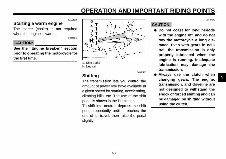
ShiftingThe transmission lets you control theamount of power you have available ata given speed for starting, accelerating,climbing hills, etc. The use of the shiftpedal is shown in the illustration.To shift into neutral, depress the shiftpedal repeatedly until it reaches theend of its travel, then raise the pedalslightly.
C@
@
1. Shift pedalN. Neutral

O
5
Re(foTheshoCF-25
NO@
Whto spe@
EAU01128
gine break-inre is never a more important period
he life of your motorcycle than theiod between zero and 1,600 km. For reason we ask that you carefullyd the following material. Because engine is brand new, you must not an excessive load on it for the first00 km. The various parts in the en-e wear and polish themselves to therect operating clearances. During period, prolonged full throttle oper-n, or any condition which might re- in excessive heating of the engine,st be avoided.
PERATION AND IMPORTANT RIDING POINTS
5-5
EAU02941
commended shift points r Switzerland only) recommended shift points arewn in the table below.
E
TE:en shifting two gears down from 4th2nd, bring your motorcycle to aed of 35 km/h.
EAU00424
Tips for reducing fuel consumptionYour motorcycle’s fuel consumptiondepends to a large extent on yourriding style. The following tips can helpreduce fuel consumption:
● Warm up the engine before riding.● Turn off the starter (choke) as
soon as possible.● Shift up swiftly and avoid high en-
gine speeds during acceleration.● Do not double-clutch or rev the en-
gine while shifting down and avoidhigh engine speeds with no loadon the engine.
● Turn off the engine instead of let-ting it idle for an extended lengthof time, i.e. in traffic jams, at trafficlights or railroad crossings.
EnThein tperthisreatheput1,6gincorthisatiosultmu
Acceleration shift point(km/h)
1st → 2nd2nd → 3rd3rd → 4th4th → 5th
23365060

ANT RIDING POINTS
5
0 Av
1,Av5,
C@
Aftoel@
1,Pr
C@
@
OPERATION AND IMPORT
5-6
EAU01329*
~ 1,000 kmoid operation above 4,000 r/min.
000 ~ 1,600 kmoid cruising speeds in excess of
000 r/min.EC000052*
AUTION:ter 1,000 km of operation, be sure replace the engine oil and oil filterement.
600 km and beyondoceed with normal riding.
EC000053*
AUTION:● Never let the engine speed enter
the red zone.● If any engine trouble should oc-
cur during the break-in period,consult a Yamaha dealer imme-diately.
EAU00460
ParkingWhen parking the motorcycle, stop theengine and remove the ignition key.
EW000058
WARNING@
The exhaust system is hot. Park themotorcycle in a place where pedes-trians or children are not likely totouch the motorcycle. Do not parkthe motorcycle on a slope or softground; the motorcycle may over-turn.@


6
PERIODIC MAINTENANCE AND MINOR REPAIR
Tool kit...................................................................6-1Periodic maintenance and lubrication...................6-2Panel removal and installation ..............................6-5Panel A .................................................................6-5Spark plugs...........................................................6-6Engine oil ..............................................................6-7Air filter ...............................................................6-10Carburetor adjustment ........................................6-11Idle speed adjustment ........................................6-11Throttle cable free play inspection ......................6-12Valve clearance adjustment ................................6-12Tires....................................................................6-13Wheels................................................................6-16Rear brake pedal height adjustment...................6-16Brake light switch adjustment .............................6-17Checking the front and rear brake pads..............6-17Inspecting the brake fluid level............................6-18Brake fluid replacement ......................................6-19Drive chain slack check ......................................6-19Drive chain slack adjustment ..............................6-19
Drive chain lubrication........................................ 6-20Cable inspection and lubrication ........................ 6-20Throttle cable and grip lubrication...................... 6-21Brake and shift pedal lubrication ........................ 6-21Brake and clutch lever lubrication ...................... 6-21Center and sidestand lubrication ....................... 6-22Front fork inspection........................................... 6-22Steering inspection ............................................ 6-23Wheel bearings .................................................. 6-23Battery................................................................ 6-23Fuse replacement .............................................. 6-25Headlight bulb replacement ............................... 6-25Tail/brake light bulb replacement........................ 6-27Turn signal light bulb replacement...................... 6-27Front wheel removal........................................... 6-28Front wheel installation ...................................... 6-29Rear wheel removal ........................................... 6-30Rear wheel installation....................................... 6-31Troubleshooting.................................................. 6-31Troubleshooting chart......................................... 6-32

6
EAU00462
TE:ou do not have necessary tools re-red during a service operation, take
6-PE
Perbric
r motorcycle to a Yamaha dealer forvice.
EW000063
WARNINGdifications to this motorcycle notroved by Yamaha may cause of performance, and render itafe for use. Consult a Yamahaler before attempting any chang-
the posmoandbe geninteCOTERTIOUATHATIMTERROof mandlow
@
If ycycdon@
6-1
RIODIC MAINTENANCE AND MINOR REPAIREAU00464
iodic inspection, adjustment and lu-ation will keep your motorcycle insafest and most efficient conditionsible. Safety is an obligation of thetorcycle owner. The maintenance lubrication schedule chart shouldconsidered strictly as a guide toeral maintenance and lubricationrvals. YOU MUST TAKE INTONSIDERATION THAT WEATHER,RAIN, GEOGRAPHICAL LOCA-
NS, AND A VARIETY OF INDIVID-L USES ALL TEND TO DEMAND
T EACH OWNER ALTER THISE SCHEDULE TO SHORTER IN-VALS TO MATCH THE ENVI-
NMENT. The most important pointsotorcycle inspection, adjustment,
lubrication are explained in the fol-ing pages.
EW000060
WARNINGou are not familiar with motor-le service, this work should bee by a Yamaha dealer.
EAU00469
Tool kitThe service information included in thismanual is intended to provide you, theowner, with the necessary informationfor completing some of your own pre-ventive maintenance and minor re-pairs. The tools provided in the owner’stool kit are to assist you in the perfor-mance of periodic maintenance. How-ever, some other tools such as a torquewrench are also necessary to performthe maintenance correctly.
NO@
If yquiyouser@
@
Moapplossunsdeaes.@
1. Tool kit

AND MINOR REPAIR
6
EAU00473
IONCP
N INITIAL(1,000 km)
EVERY
6,000 km or
6 months(whichevercomes first)
12,000 km or
12 months(whichevercomes first)
1 √ √
2 √
3 √ √ √
4 Every 24,000 km or 24 months (whichever comes first)
5 √ √
6 √ √ √
7 √ √ √
8 √ √ √
9 √ √
PERIODIC MAINTENANCE
6-2
PERIODIC MAINTENANCE AND LUBRICAT-01E
O. ITEM CHECKS AND MAINTENANCE JOBS
* Fuel line • Check fuel hoses and vacuum hose for cracks or damage. • Replace if necessary.
* Fuel filter • Check condition. • Replace if necessary.
Spark plugs • Check condition. • Clean, regap or replace if necessary.
* Valves • Check valve clearance. • Adjust if necessary.
Air filter • Clean or replace if necessary.
* Clutch• Check operation, fluid level and vehicle for fluid leakage.
(See NOTE on page 6-4.) • Correct accordingly.
* Front brake
• Check operation, fluid level and vehicle for fluid leakage. (See NOTE on page 6-4.)
• Correct accordingly.• Replace brake pads if necessary.
* Rear brake
• Check operation, fluid level and vehicle for fluid leakage. (See NOTE on page 6-4.)
• Correct accordingly.• Replace brake pads if necessary.
* Wheels • Check balance, runout and for damage. • Rebalance or replace if necessary.

PE
6
10 √ √
11 √ √
12 √ √
13 Every 1,000 km and after washing themotorcycle or riding in the rain
14 √ √
15 √ √
16 √ √
17 √ √ √
18 √ √
19 √ √
NO INITIAL(1,000 km)
EVERY
6,000 km or
6 months(whichevercomes first)
12,000 km or
12 months(whichevercomes first)
RIODIC MAINTENANCE AND MINOR REPAIR
6-3
* Tires
• Check tread depth and for damage.• Replace if necessary.• Check air pressure.• Correct if necessary.
* Wheel bearings • Check bearing for looseness or damage. • Replace if necessary.
* Swingarm
• Check swingarm pivoting point for play.• Correct if necessary. • Lubricate with molybdenum disulfide grease every 24,000 km or
24 months (whichever comes first).
Drive chain
• Check chain slack. • Adjust if necessary. Make sure that the rear wheel is properly
aligned.• Clean and lubricate.
* Steering bearings
• Check bearing play and steering for roughness.• Correct accordingly. • Lubricate with lithium soap base grease every 24,000 km
or 24 months (whichever comes first).
* Chassis fasteners • Make sure that all nuts, bolts and screws are properly tightened.• Tighten if necessary.
Sidestand/centerstand • Check operation.• Lubricate and repair if necessary.
* Sidestand switch • Check operation. • Replace if necessary.
* Front fork • Check operation and for oil leakage. • Correct accordingly.
*Rear shock absorber assemblies
• Check operation and shock absorbers for oil leakage.• Replace shock absorber assembly if necessary.
. ITEM CHECKS AND MAINTENANCE JOBS

AND MINOR REPAIR
6
* S aler.EAU02971
N@
y areas.
ys replace the brake fluid. Check the fill as required.h release cylinder every two years.
@
20 √ √ √
21 √ √ √
22 √ √
N INITIAL(1,000 km)
EVERY
6,000 km or
6 months(whichevercomes first)
12,000 km or
12 months(whichevercomes first)
PERIODIC MAINTENANCE
6-4
ince these items require special tools, data and technical skills, they should be serviced by a Yamaha de
OTE:● The air filter needs more frequent service if you are riding in unusually wet or dust● Hydraulic brake and clutch systems
• After disassembling the master cylinder, caliper or clutch release cylinder, alwabrake fluid level of the master cylinder and clutch release cylinder regularly and
• Replace the oil seals on the inner parts of the master cylinder, caliper and clutc• Replace the brake and clutch hoses every four years or if cracked or damaged.
* Carburetors • Check engine idling speed, synchronization and starter operation. • Adjust if necessary.
Engine oil• Check oil level and vehicle for oil leakage. • Correct if necessary.• Change. (Warm engine before draining.)
Engine oil filter element • Replace.
O. ITEM CHECKS AND MAINTENANCE JOBS

PE
6
PaThemonanto tto b
installert the projection into the grommet tighten the panel screws.
1. P rojectionrommet
RIODIC MAINTENANCE AND MINOR REPAIR
6-5
EAU01777
nel removal and installation panel illustrated needs to be re-
ved to perform some of the mainte-ce described in this chapter. Referhis section each time the panel hase removed or installed.
EAU01551
Panel ATo removeRemove the seat and panel screws.Then pull the panel outward as shown.
To Insand
anel A 1. Screw (× 2)2. Pull out
1. P2. G

AND MINOR REPAIR
6
SR
1
If one spark plug shows a distinctlyferent color, there could be some-ing wrong with the engine. not attempt to diagnose such prob-s yourself. Instead, take the motor-
cle to a Yamaha dealer. You shouldriodically remove and inspect theark plugs because heat and depositsll cause any spark plug to slowlyeak down and erode. If electrode ero-n becomes excessive, or if carbond other deposits are excessive, youould replace the spark plug with theecified plug.
1.
Specified spark plug:DPR8EA-9 (NGK) or X24EPR-U9 (DENSO)
PERIODIC MAINTENANCE
6-6
EAU03053
park plugsemoval. Remove the spark plug caps.
2. Use the spark plug wrench in thetool kit to remove the spark plugsas shown.
InspectionThe spark plug is an important enginecomponent and is easy to inspect. Thecondition of the spark plug can indicatethe condition of the engine.Normally, all spark plugs from thesame engine should have the samecolor on the white insulator around thecenter electrode. The ideal color at thispoint is a medium-to-light tan color for amotorcycle that is being ridden normal-
ly.difthDolemcypespwibrsioanshsp
Spark plug cap 1. Spark plug wrench

PE
6
Ins1.
2.
3.
EAU01784*
gine oillevel inspectionPlace the motorcycle on the cen-terstand. Warm up the engine forseveral minutes.
TE:sure the motorcycle is positionedight up when checking the oil level.light tilt toward the side can result ine readings.
a. S
S
RIODIC MAINTENANCE AND MINOR REPAIR
6-7
tallationMeasure the electrode gap with awire thickness gauge and, if nec-essary, adjust the gap to specifica-tion.
Clean the gasket surface. Wipe offany grime from the threads.Install the spark plug and tighten itto the specified torque.
NOTE:@
If a torque wrench is not available whenyou are installing a spark plug, a goodestimate of the correct torque is 1/4 to1/2 turn past finger tight. Have thespark plug tightened to the specifiedtorque as soon as possible. @
4. Install the spark plug caps.
EnOil
1.
NO@
Be straA sfals@
park plug gap
park plug gap:0.8 ~ 0.9 mm
Tightening torque:Spark plug:
17.5 Nm (1.75 m·kg)

AND MINOR REPAIR
6
2
N@
Wse@
3
. Remove the oil filter drain screw,filter cover bolt, filter cover, oil filterelement and O-ring.
. Reinstall the drain bolt and tightenit to the specified torque.
1.2.3.
Oil filter drain screwOil filter cover bolt
Tightening torque:Drain bolt:
43 Nm (4.3 m·kg)
PERIODIC MAINTENANCE
6-8
. With the engine stopped, checkthe oil level through the level win-dow located at the lower part ofthe right side crankcase cover.
OTE:ait a few minutes until the oil levelttles before checking.
. The oil level should be betweenthe maximum and minimum levelmarks. If the level is low, add suffi-cient oil to raise it to the specifiedlevel.
Engine oil and oil filter element re-placement
1. Warm up the engine for severalminutes.
2. Stop the engine. Place an oil panunder the engine and remove theoil filler cap.
3. Remove the drain bolt and drainthe oil.
4
5
Oil level windowMaximum level markMinimum level mark
1. Engine oil drain bolt 1.2.

PE
6
6.
Fill engine with oil. Install the oil fill-er cap and tighten.
EC000066
UTION:Do not put in any chemical addi-tives. Engine oil also lubricatesthe clutch and additives couldcause clutch slippage.Be sure no foreign material en-ters the crankcase.
1. O2. O
ecommended oil:See page 8-1.
il quantity:Total amount:
4.2 LPeriodic oil change:
3.0 LWith oil filter replacement:
3.35 L
RIODIC MAINTENANCE AND MINOR REPAIR
6-9
Install the new oil filter elementand O-ring.
7. Align the projection on the filtercover with the slot in housing andinstall the filter cover.
8. Tighten the oil filter bolt and oil fil-ter drain screw to the specifiedtorque.
NOTE:@
Make sure the O-rings are seated prop-erly. @
9.
CA@
●
●
@
il filter element-ring (× 2)
1. Projection2. Slot
Tightening torque:Oil filter bolt:
15 Nm (1.5 m·kg)Oil filter drain screw:
7 Nm (0.7 m·kg)
R
O

AND MINOR REPAIR
6
10
N@
Afinto@
C@
If mgide@
. Pull out the air filter.
Air filter
PERIODIC MAINTENANCE
6-10
. Start the engine and warm it up forseveral minutes. While warmingup, check for oil leakage. If oilleakage is found, stop the engineimmediately and check for thecause.
OTE:ter the engine is started, the oil leveldicator light should go off if oil is filled the specified level.
EC000067
AUTION:the indicator light flickers or re-ains on, immediately stop the en-ne and consult with a Yamahaaler.
EAU01755
Air filterThe air filter should be cleaned at thespecified intervals. It should be cleanedmore frequently if you are riding in un-usually wet or dusty areas.
1. Remove the seat. (See page 3-11for seat removal and installationprocedures.)
2. Remove panel A. (See page 6-5for panel removal and installationprocedures.)
3. Remove the air filter case cover bylifting up the wires as shown andremoving the screws.
4
1. Air filter case cover2. Screw (× 4)
1.

PE
6
5.
6.
CA@
●
●
@
EAU00632
speed adjustmentStart the engine and warm it up fora few minutes at approximately1,000 to 2,000 r/min. Occasionallyrev the engine to 4,000 to5,000 r/min. The engine is warmwhen it quickly responds to thethrottle.
RIODIC MAINTENANCE AND MINOR REPAIR
6-11
Tap the air filter lightly to removemost of the dust and dirt and blowout the remaining dirt with com-pressed air as shown. If the air fil-ter is damaged, replace it.Reassemble by reversing the re-moval procedure.
EC000082
UTION:Make sure the air filter is prop-erly seated in the air filter case.The engine should never be runwithout the air filter installed.Excessive piston and/or cylin-der wear may result.
EAU00630
Carburetor adjustmentThe carburetors are important parts ofthe engine and require very sophisti-cated adjustment. Most adjustmentsshould be left to a Yamaha dealer whohas the professional knowledge andexperience to do so. However, the idlespeed may be adjusted by the owneras part of routine maintenance.
EC000095
CAUTION:@
The carburetors were set at theYamaha factory after many tests. Ifthey are changed, poor engine per-formance and damage may result. @
Idle1.

AND MINOR REPAIR
6
2
N@
If obju@
EAU00637
alve clearance adjustmente correct valve clearance changesth use, resulting in improper fuel/airpply or engine noise. To prevent this,e valve clearance must be adjustedgularly. This adjustment however,ould be left to a professionalmaha service technician.
1.
PERIODIC MAINTENANCE
6-12
. Set the idle to the specified enginespeed by adjusting the throttlestop screw. Turn the screw in di-rection a to increase enginespeed and in direction b to de-crease engine speed.
OTE:the specified idle speed cannot betained by performing the above ad-
stment, consult a Yamaha dealer.
EAU00635
Throttle cable free play inspectionThere should be a free play of 3 ~5 mm at the throttle grip. If the free playis incorrect, ask a Yamaha dealer tomake this adjustment.
VThwisuthreshYa
Throttle stop screw
Standard idle speed:1,000 ~ 1,100 r/min
a. Free play

PE
6
TirTo lonthe
TireAlwsur
@
Tirechetemamtioncorride(faifor @
EW000083
WARNINGper loading of your motorcycleportant for several characteris-
of your motorcycle, such asdling, braking, performance and
ety. Do not carry loosely packeds that can shift. Securely packr heaviest items close to theter of the motorcycle, and dis-ute the weight evenly from sideide. Properly adjust the suspen- for your load, and check thedition and pressure of your tires.VER OVERLOAD YOUR MOTOR-CLE. Make sure the total weighthe cargo, rider, passenger, andessories (fairing, saddlebags,. if approved for this model) does exceed the maximum load of thetorcycle. Operation of an over-ded motorcycle could cause tire
age, an accident, or even injury.
RIODIC MAINTENANCE AND MINOR REPAIR
6-13
EAU00658
esensure maximum performance,
g service and safe operation, note following:
air pressureays check and adjust the tire pres-e before operating the motorcycle.
EW000082
WARNING inflation pressure should becked and adjusted when theperature of the tire equals thebient air temperature. Tire infla- pressure must be adjusted ac-ding to total weight of cargo,r, passenger, and accessories
ring, saddlebags, etc. if approvedthis model), and vehicle speed.
CE-33E
@
Prois imticshansafitemyoucentribto ssionconNECYof taccetcnotmoloadam@
Maximum load* 207 kg
Cold tire pressure Front Rear
Up to 90 kg load*250 kPa
(2.50 kg/cm2,2.50 bar)
250 kPa(2.50 kg/cm2,
2.50 bar)
90 kg Maximum load*250 kPa
(2.50 kg/cm2,2.50 bar)
290 kPa(2.90 kg/cm2,
2.90 bar)
High speed riding250 kPa
(2.50 kg/cm2,2.50 bar)
290 kPa(2.90 kg/cm2,
2.90 bar)
* Load is the total weight of cargo, rider, passengerand accessories.

AND MINOR REPAIR
6
TiAlthrehathYath
re informationis motorcycle is equipped with tube-s tires, tire valves and cast wheels.
1.a.
Tire valveValve coreValve cap with seal
PERIODIC MAINTENANCE
6-14
re inspectionways check the tires before operatinge motorcycle. If center tread depthaches the limit as shown, if the tires a nail or glass fragments in it, or if
e side wall is cracked, contact amaha dealer immediately and have
e tire replaced.
EW000095
WARNING@
Operating the motorcycle with ex-cessively worn tires decrease ridingstability and can lead to loss of con-trol. Have excessively worn tires re-placed by a Yamaha dealerimmediately. Brakes, tires, and relat-ed wheel parts replacement shouldbe left to a Yamaha Service Techni-cian. @
CE-26E
NOTE:@
These limits may be different by regula-tion from country to country. If so, con-form to the limits specified by theregulations of your own country. @
TiThles
Side wallTread depth
Minimum tire tread depth (front and rear)
1.6 mm
1.2.3.

PE
6
@
●
●
●
@
EAU00684
WARNINGs motorcycle is fitted with superh-speed running tires. The fol-ing points must be observed iner for you to make fully effective of these tires.Never fail to use the specifiedtires in tire replacement. Othertires may have a danger ofbursting at super high-speeds.New tires have a relatively lowgrip on the road surface untilthey have been slightly worn.Therefore, approximately 100 kmshould be traveled at normalspeed before any high-speedriding is done.Before any high-speed runs, thetires should be warmed-up suf-ficiently.Always inflate to the correct tirepressure according to the oper-ating conditions.
RIODIC MAINTENANCE AND MINOR REPAIR
6-15
EW000080
WARNINGAfter extensive tests, the tiresmentioned below have been ap-proved by Yamaha Motor Co.,Ltd. for this model. No guaran-tee for handling characteristicscan be given if tire combina-tions other than what is ap-proved are used on thismotorcycle. The front and reartires should be of the samemanufacture and design.The use of tire valves and valvecores other than listed belowcould cause tire deflation dur-ing extreme high speed riding.Always use genuine parts ortheir equivalent for replace-ment.Be sure to install the valve capssecurely, as these are importantto prevent air pressure leakageduring extreme high speedriding.
CE-10E
CE-12E
@
Thihigloworduse
●
●
●
●
@
FRONT
Manufacturer Size Type
Dunlop 120/70ZR17 (58W) D207F
Bridgestone 120/70ZR17 (58W) BT57F
Michelin 120/70ZR17 (58W) MACADAM90X
REAR
Manufacturer Size Type
Dunlop 180/55ZR17 (73W) D207
Bridgestone 180/55ZR17 (73W) BT57R
Michelin 180/55ZR17 (73W) MACADAM90X
Type
Tire valve TR412
Valve core #9000A (original)
AND MINOR REPAIR
6
WToloth
EW000109
WARNINGsoft or spongy feeling in the brakedal can indicate the presence of in the brake system. This airust be removed by bleeding theake system before the motorcycleoperated. Air in the system willuse greatly diminished brakingpability and can result in loss ofntrol and an accident. Have amaha dealer inspect and bleed
e system if necessary.
PERIODIC MAINTENANCE
6-16
EAU00687
heels ensure maximum performance,
ng service, and safe operation, notee following:● Always inspect the wheels before
a ride. Check for cracks, bends, orwarpage of the wheels. If any ab-normal condition exists in a wheel,consult a Yamaha dealer. Do notattempt even small repairs to thewheel. If a wheel is deformed orcracked, it must be replaced.
● Tires and wheels should be bal-anced whenever either one ischanged or replaced. Failure tohave a wheel balanced can resultin poor performance, adverse han-dling characteristics, and short-ened tire life.
● Ride at moderate speeds afterchanging a tire since the tire sur-face must first be broken in for it todevelop its optimal characteristics.
EAU00712
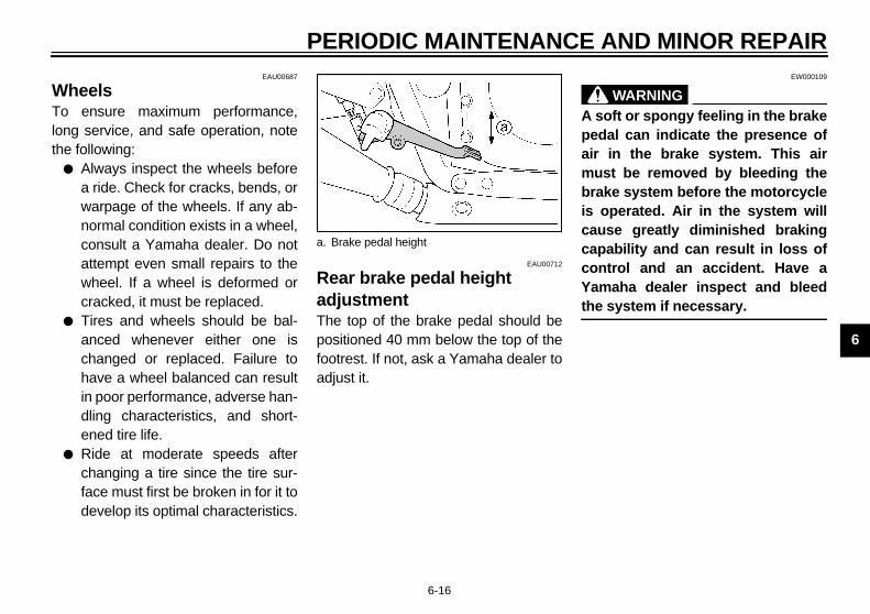
Rear brake pedal height adjustmentThe top of the brake pedal should bepositioned 40 mm below the top of thefootrest. If not, ask a Yamaha dealer toadjust it.
@
A peairmbris cacacoYath@
a. Brake pedal height

PE
6
BrTheby jusjusthe
1.
2.
EAU00715
ecking the front and rear ke padsear indicator is provided on each
ke. This indicator allows checking ofke pad wear without disassembling brake. Apply the brake and inspect wear indicator. If the indicator is
OST in contact with the disc plate, a Yamaha dealer to replace thes.
1. B2. A
ear indicator (× 2)
ont Rear
RIODIC MAINTENANCE AND MINOR REPAIR
6-17
EAU01756
ake light switch adjustment rear brake light switch is activated
the brake pedal and is properly ad-ted when the brake light comes ont before braking takes effect. Adjust brake light switch as follows.
Remove panel A. (See page 6-5for panel removal and installationprocedures.)Hold the switch body so it does notrotate while turning the adjustingnut.
3. Turn the adjusting nut indirection a to make the brakelight come on earlier.Turn the adjusting nut indirection b to make the brakelight come on later.
ChbraA wbrabrathetheALMaskpad
rake light switchdjusting nut
1. W
Fr

AND MINOR REPAIR
6
InInthcaBeiswmflulofote
NThhi
● Be careful that water does not en-ter the master cylinder when refill-ing. Water will significantly lowerthe boiling point of the fluid andmay result in vapor lock.
● Brake fluid may deteriorate paint-ed surfaces or plastic parts. Al-ways clean up spilled fluidimmediately.
● Have a Yamaha dealer check thecause if the brake fluid level goesdown.
1.
F
Minimum level mark
lutch
PERIODIC MAINTENANCE
6-18
EAU01800*
specting the brake fluid levelsufficient brake fluid may let air entere brake or clutch system, possiblyusing them to become ineffective.fore riding, check that the brake fluid
above the minimum level and fillhen necessary. Low brake fluid levelsay indicate worn brake pads and/orid leakage. If the brake fluid level isw, be sure to inspect the brake padsr wear and the brake and clutch sys-ms for leakage.
OTE:e rear master cylinder is located be-
nd panel A.
Observe these precautions:● When checking the fluid level,
make sure the top of the mastercylinder is level by turning the han-dlebars.
● Use only the designated qualitybrake fluid. Otherwise, the rubberseals may deteriorate, causingleakage and poor brake or clutchperformance.
● Refill with the same type of brakefluid. Mixing fluids may result in aharmful chemical reaction andlead to poor brake or clutch perfor-mance.
Minimum level mark
ront
1. Minimum level mark
Recommended brake fluid: DOT 4
Rear
1.
C

PE
6
BrTheby Hafollmaage
●
●
EAU01251
ve chain slack adjustmentLoosen the axle nut.Loosen the locknuts on each side.To tighten the chain, turn the chainadjusting bolts in direction a. To loosen the chain, turn the ad-justing bolts in direction b andpush the wheel forward. Turn eachadjusting bolt exactly the sameamount to maintain correct axlealignment. There are marks oneach side of the swingarm. Usethese marks to align the rearwheel.
ocknutdjusting boltxle nutlignment marks
RIODIC MAINTENANCE AND MINOR REPAIR
6-19
EAU00742
ake fluid replacement brake fluid should be replaced only
trained Yamaha service personnel.ve the Yamaha dealer replace theowing components during periodicintenance or when they are dam-d or leaking:oil seals (every two years)brake hoses (every four years)
EAU00745
Drive chain slack check
NOTE:@
Spin the wheel several times and findthe tightest position of the chain. Checkand/or adjust the chain slack while it’sin this tightest position. @
Inspect the drive chain when the motor-cycle is on the centerstand. Check theslack at the position shown in the illus-tration. Normal slack is approximately20 ~ 30 mm. If the slack exceeds30 mm, adjust.
Dri1.2.
a. Chain slack 1. L2. A3. A4. A

AND MINOR REPAIR
6
C@
TothKelim@
3
EAU02962
able inspection and brication
EW000112
WARNINGmage to the outer housing of ca-s may lead to internal rusting and
erfere with the cable movement.place damaged cables as soon asssible to prevent unsafe condi-ns.
bricate the cables and cable ends. Ifcable does not operate smoothly, askYamaha dealer to replace it.
Recommended lubricant:Engine oil
PERIODIC MAINTENANCE
6-20
EC000096
AUTION:o little chain slack will overload
e engine and other vital parts.ep the slack within the specifiedits.
. After adjusting, tighten the lock-nuts. Then tighten the axle nut tothe specified torque.
EAU03006
Drive chain lubricationThe chain consists of many parts whichwork with each other. If the chain is notmaintained properly, it will wear outquickly. Therefore, the chain must beserviced regularly. This service is es-pecially necessary when riding in dustyareas. This motorcycle is equippedwith a sealed type chain. Steam clean-ing, high-pressure washers, and sol-vents can damage the drive chain, sodo not use these for cleaning it. Useonly kerosene to clean the drive chain.Wipe it dry, and thoroughly lubricate itwith SAE 30 ~ 50W motor oil. Do notuse any other lubricants on the drivechain. They may contain solvents thatcould damage the sealed chain.
EC000097
CAUTION:@
Be sure to oil the chain after wash-ing the motorcycle or riding in therain. @
Clu
@
DableintRepotio@
Lua a
Tightening torque:Axle nut:
150 Nm (15.0 m·kg)

PE
6
ThlubThebe lubmocabtheputthemea s
EAU02985
ke and clutch lever ricationricate the pivoting parts.
ecommended lubricant:Engine oil
RIODIC MAINTENANCE AND MINOR REPAIR
6-21
EAU00773
rottle cable and grip rication throttle twist grip assembly should
greased at the time that the cable isricated, since the grip must be re-ved to get at the end of the throttlele. After removing the screws, hold end of the cable up in the air and in several drops of lubricant. With throttle grip disassembled, coat thetal surface of the grip assembly withuitable all-purpose grease.
EAU02984
Brake and shift pedal lubricationLubricate the pivoting parts.
BralubLub
Recommended lubricant:Engine oil
R

AND MINOR REPAIR
6
CluLujosily
@
If noYa@
peration check. Place the motorcycle on a level
place.. Hold the motorcycle in an upright
position and apply the front brake.. Push down hard on the handle-
bars several times and check if thefork rebounds smoothly.
EC000098
AUTION:any damage or unsmooth move-ent is found with the front fork,nsult a Yamaha dealer.
PERIODIC MAINTENANCE
6-22
EAU02965
enter and sidestand bricationbricate the pivoting and mating
ints. Check to see that the center anddestand move up and down smooth-.
EW000114
WARNINGthe center and/or sidestand doest move smoothly, consult amaha dealer.
EAU02939
Front fork inspectionVisual check
EW000115
WARNING@
Securely support the motorcycle sothere is no danger of it falling over. @
Check for scratches or damage on theinner tube and excessive oil leakagefrom the front fork.
O1
2
3
C@
If mco@
Recommended lubricant:Engine oil

PE
6
StePestebeastafronlowmoanydeaingwh
EAU01271
tterys motorcycle is equipped with aled-type battery. Therefore it is notessary to check the electrolyte or fill battery with distilled water.
If the battery seems to have dis-charged, consult a Yamaha deal-er.If the motorcycle is equipped withoptional electrical accessories, thebattery tends to discharge morequickly, so be sure to recharge itperiodically.
RIODIC MAINTENANCE AND MINOR REPAIR
6-23
EAU00794
ering inspectionriodically inspect the condition of theering. Worn out or loose steeringrings may be dangerous. Place a
nd under the engine to raise thet wheel off the ground. Hold theer end of the front forks and try tove them forward and backward. If free play can be felt, ask a Yamahaler to inspect and adjust the steer-
. Inspection is easier if the fronteel is removed.
EW000115
WARNING@
Securely support the motorcycle sothere is no danger of it falling over. @
EAU01144
Wheel bearingsIf there is play in the front or rear wheelhub or if the wheel does not turnsmoothly, have a Yamaha dealer in-spect the wheel bearings.
BaThiseanecthe
●
●

AND MINOR REPAIR
6
@
BadaetcoAN
BaKeawusshbaKED@
PERIODIC MAINTENANCE
6-24
EW000116
WARNINGttery electrolyte is poisonous andngerous, causing severe burns,c. It contains sulfuric acid. Avoidntact with skin, eyes or clothing.TIDOTE:
● EXTERNAL: Flush with water.● INTERNAL: Drink large quanti-
ties of water or milk. Follow withmilk of magnesia, beaten egg,or vegetable oil. Call a physi-cian immediately.
● EYES: Flush with water for15 minutes and get promptmedical attention.
tteries produce explosive gases.ep sparks, flame, cigarettes etc.,ay. Ventilate when charging oring in an enclosed space. Alwaysield your eyes when working neartteries.EP OUT OF REACH OF CHIL-
REN.
Battery storageWhen the motorcycle is not used for amonth or longer, remove the battery,fully charge it and store it in a cool, dryplace.
EC000102
CAUTION:@
● Completely recharge the bat-tery before storing. Storing adischarged battery can causepermanent battery damage.
● Use a battery charger designedfor a sealed-type (MF) battery.Using a conventional batterycharger will cause battery dam-age. If you do not have a sealed-type battery charger, contactyour Yamaha dealer.
● Always make sure the connec-tions are correct when reinstall-ing the battery.
@

PE
6 FuThe(SeinsIf aswqueamseethesul
EAU00832
adlight bulb replacements motorcycle is equipped with artz bulb headlight. If the headlight
b burns out, replace the bulb as fol-s:Remove the screws holding theheadlight assembly.
1. M2. S3. H4. I5. S
crew (× 2)
RIODIC MAINTENANCE AND MINOR REPAIR
6-25
EAU01470
se replacement fuse box is located under the seat.e page 3-11 for seat removal andtallation procedures.)ny fuse is blown, turn off the mainitch and the switch of the circuit instion. Install a new fuse of specifiedperage. Turn on the switches and if the electrical device operates. If fuse immediately blows again, con-t a Yamaha dealer.
EC000103
CAUTION:@
Do not use fuses of higher amper-age rating than those recommend-ed. Substitution of a fuse ofimproper rating can cause extensiveelectrical system damage and pos-sibly a fire. @
HeThiquabullow
1.
ain fuseignaling system fuseeadlight fuse
gnition fusepare fuse (× 3)
Specified fuses:Main fuse: 30 AIgnition fuse: 7.5 ASignaling system fuse: 15 AHeadlight fuse: 15 A
1. S

AND MINOR REPAIR
6
2EC000105
AUTION:oid touching the glass part of alb. Keep it free from oil; other-se, the transparency of the glass, of the bulb, and luminous flux
ll be adversely affected. If oil gets a bulb, thoroughly clean it with ath moistened with alcohol or lac-er thinner.
. Install the bulb cover and theheadlight connector. If the head-light beam adjustment is neces-sary, ask a Yamaha dealer tomake that adjustment.
1.2.
Don’t touch
PERIODIC MAINTENANCE
6-26
. Remove the headlight connectorand the bulb cover.
3. Unhook the bulb holder and re-move the defective bulb.
EW000119
WARNING@
Keep flammable products and yourhands away from a bulb while it ison, as it is hot. Do not touch a bulbuntil it cools down.@
4. Put a new bulb into position andsecure it in place with the bulbholder.
C@
Avbuwilifewioncloqu@
5
ConnectorBulb cover
1. Bulb holder 1.

PE
6
Tarep
1.2.
3.
4.
5.
6.
Remove the defective bulb bypushing it inward and turning itcounterclockwise.Install a new bulb by pushing it in-ward and turning it clockwise.Install the lens and tighten thescrew.
ulb
RIODIC MAINTENANCE AND MINOR REPAIR
6-27
EAU00856*
il/brake light bulb lacementRemove the seat.To remove the socket, turn it coun-terclockwise.To remove the defective bulb, turnit counterclockwise.Push a new bulb into the socketand turn it clockwise.Install the socket and turn it clock-wise.Install the seat.
EAU01095
Turn signal light bulb replacement
1. Remove the screw and the lens.
2.
3.
4.
1. Screw 1. B

AND MINOR REPAIR
6
F
@
@
1
2
TE: not depress the brake lever when
e disc and caliper are separated.
. Loosen the pinch bolt and wheelaxle.
. Elevate the front wheel by placinga suitable stand under the engine.
. Remove the wheel axle. Makesure the motorcycle is properlysupported.
1. Pinch boltWheel axle
PERIODIC MAINTENANCE
6-28
EAU00869
ront wheel removalEW000122
WARNING● It is advisable to have a Yamaha
dealer service the wheel.● Securely support the motor-
cycle so there is no danger of itfalling over.
. Place the motorcycle on the cen-terstand.
. Remove the speedometer cablefrom the front wheel side.
3. Remove the brake hose holdersand the calipers by removing thebolts.
NO@
Doth@
4
5
6
Speedometer cable 1. Bolt (× 3)2. Brake hose holder3. Caliper
Left Right
1.2.

PE
6
Fro1.
Tighten the wheel axle, pinch boltand caliper bolts to the specifiedtorques.
Install the speedometer cable.Push down hard on the handle-bars several times to check forproper fork operation.
ightening torque:Wheel axle:
73 Nm (7.3 m·kg)Pinch bolt:
19 Nm (1.9 m·kg)Caliper bolt:
40 Nm (4.0 m·kg)
RIODIC MAINTENANCE AND MINOR REPAIR
6-29
EAU01758*
nt wheel installationInstall the speedometer gear unithousing into the wheel hub. Makesure the wheel hub and the speed-ometer gear unit housing are in-stalled with the projectionsmeshed into the slots.
2. Lift up the wheel between the frontfork legs. Make sure the slot in thespeedometer gear unit housing fitsover the stopper on the front forkouter tube.
3. Install the wheel axle and let themotorcycle down.
4. Install the calipers, caliper boltsand brake hose holders. Makesure there is enough gap betweenthe brake pads before installingthe calipers onto the brake discs.
5.
6.7.
T

AND MINOR REPAIR
6
R
@
@
1
2
TE:● Do not depress the brake pedal
when the caliper is off the disc asthe brake pads will be forced shut.
● You do not have to disassemblethe chain in order to remove or in-stall the rear wheel.
1.2.3.
PERIODIC MAINTENANCE
6-30
EAU01318
ear wheel removalEW000122
WARNING● It is advisable to have a Yamaha
dealer service the wheel.● Securely support the motor-
cycle so there is no danger of itfalling over.
. Loosen the axle nut and caliperbolts.
. Remove the brake torque rod nutand bolt.
3. Place the motorcycle on the cen-terstand.
4. Remove the axle nut, caliper boltsand caliper.
5. Loosen the locknuts and chain ad-justing nuts on each side of theswingarm.
6. Push the wheel forward and re-move the drive chain.
7. Support the caliper bracket, pullout the wheel axle and remove thewheel assembly by pulling it back-wards.
NO@
@
LocknutAdjusting boltAxle nut
1. Wheel axle

PE
6
Re1.
2.
3.
4.
5.
6.
EAU01008
ubleshootingough Yamaha motorcycles receive
gid inspection before shipment from factory, trouble may occur duringration. problem in the fuel, compression,ignition systems can cause poorrting and loss of power. The trouble-oting chart describes a quick, easycedure for making checks.our motorcycle requires any repair,g it to a Yamaha dealer. The skilled
hnicians at a Yamaha dealershipe the tools, experience, and know- to properly service your motor-
le. Use only genuine Yamaha partsyour motorcycle. Imitation parts mayk like Yamaha parts, but they are of- inferior. Consequently, they have arter service life and can lead to ex-sive repair bills.
RIODIC MAINTENANCE AND MINOR REPAIR
6-31
EAU01317
ar wheel installationInstall the caliper bracket andwheel assembly, then insert theaxle.Install and adjust the drive chain.(See page 6-19 for details aboutadjusting the drive chain slack.)Install the brake torque rod boltand nut.Install the caliper and caliper bolts.Make sure there is enough gapbetween the brake pads before in-stalling the caliper onto the brakedisc.Take the motorcycle off the cen-terstand.Tighten the axle nut, caliper boltsand the brake torque rod nut to thespecified torques.
TroAltha ritheopeAnyor stashoproIf ybrintechavhowcycon lootenshopen
Tightening torque:Axle nut:
150 Nm (15.0 m·kg)Caliper bolt:
40 Nm (4.0 m·kg)Brake torque rod nut:
23 Nm (2.3 m·kg)

AND MINOR REPAIR
6
Troubleshooti
WARNING@
Never check the@
Check if thin the fuel
1. Fue
Engine doesn’t start, go to battery check.
Open throttle half-way and startthe engine.
Engine doesn’t start, ask a Yamaha dealer to inspect.
t, go to compression check.
Use the electric
2. Compre
Remove spark plugs and check electrode
3. Ignition
Use the electric
4. Battery
PERIODIC MAINTENANCE
6-32
EAU01297
ng chartEW000125
fuel system while smoking or in the vicinity of an open flame.
ere is fuel tank.
lEnough fuel.
No fuel.
Go to compression check.
Supply fuel.
starter.
ssionThere is compression.
No compression.
Go to ignition check.
Ask a Yamaha dealer to inspect.
s.
Wet.
Dry.
Wipe clean with dry cloth and correct spark gap or replace spark plugs.
Ask a Yamaha dealer to inspect.
starter.
Engine turns over quickly.
Engine turns over slowly.
Battery good.
Check connections or recharge.
Engine doesn’t star

7
MOTORCYCLE CARE AND STORAGE
Care ................................................................................................... 7-1Storage............................................................................................... 7-4

7
EAU01517
aningr normal useove dirt with warm water, a neutral
7-MO
CaThea m
ergent and a soft clean sponge,n rinse with plenty of clean water. a tooth or bottle brush for hard-to-
ch parts. Tougher dirt and insects come off more easily if the area isered with a wet cloth for a few min-s before cleaning.
ablenensistremunaandyouits MovehFored clea
7-1
TORCYCLE CARE AND STORAGE
re exposure of its technology makesotorcycle charming but also vulner-. Although high-quality compo-ts are used, they are not all rust-re-ant. While a rusty exhaust pipe mayain unnoticed on a car, it does lookttractive on a motorcycle. Frequent proper care, however, will keepr motorcycle looking good, extendlife and maintain its performance.reover, the warranty states that theicle must be properly taken care of. all these reasons, it is recommend-that you observe the followingning and storing precautions.
Before cleaning1. Cover up the muffler outlets with
plastic bags.2. Make sure that all caps and covers
as well as all electrical couplersand connectors, including thespark plug caps, are tightly in-stalled.
3. Remove extremely stubborn dirt,like oil burnt onto the crankcase,with a degreasing agent and abrush, but never apply such prod-ucts onto seals, gaskets, sprock-ets, the drive chain and wheelaxles. Always rinse the dirt anddegreaser off with water.
CleAfteRemdettheUsereawillcovute

ARE AND STORAGE
7
C@
● For motorcycles equipped witha windshield: Do not use strongcleaners or hard sponges asthey will cause dulling orscratching. Some cleaningcompounds for plastic mayleave scratches on the wind-shield. Test the product on asmall hidden part of the wind-shield to make sure they do notleave any marks. If the wind-shield is scratched, use a quali-ty plastic polishing compoundafter washing.
ter riding in the rain, near the sea or salt-sprayed roadsnce sea salt or salt sprayed on theads in the winter are extremely corro-e in combination with water, carryt the following steps after each ridethe rain, near the sea or on salt-rayed roads. (Salt sprayed in thenter may remain on the roads wello spring.)
MOTORCYCLE C
7-2
ECA00010
AUTION:● Avoid using strong acidic wheel
cleaners, especially on spokedwheels. If you do use suchproducts for hard-to-removedirt, do not leave it on any long-er than instructed, then thor-oughly rinse it off with water,immediately dry the area andapply a corrosion protectionspray.
● Improper cleaning can damagewindshields, cowlings, panelsand other plastic parts. Useonly a soft, clean cloth orsponge with mild detergent andwater to clean plastic.
● Do not use any harsh chemicalproducts on plastic parts. Besure to avoid using cloths orsponges which have been incontact with strong or abrasivecleaning products, solvent orthinner, fuel (gasoline), rust re-movers or inhibitors, brake flu-id, antifreeze or electrolyte.
● Do not use high-pressure wash-ers or steam-jet cleaners sincethey cause water seepage anddeterioration in the following ar-eas: seals (of wheel bearings,swingarm bearings, forks andbrakes), electric components(couplers, connectors, instru-ments, switches and lights),breather hoses and vents.
@
AfonSirosivouin spwiint

M
7
1.
CA@
Docresal@
2.
EWA00001
WARNINGke sure that there is no oil or waxthe brakes and tires. If neces-y, clean the brake discs and lin-s with a regular brake discner or acetone, and wash the
s with warm water and mild soap.n, carefully test the motorcycle
its braking performance and cor-ing behavior.
OTORCYCLE CARE AND STORAGE
7-3
Clean your motorcycle with coldwater and soap after the enginehas cooled down.
ECA00012
UTION: not use warm water since it in-ases the corrosive action of thet.
Be sure to apply a corrosion pro-tection spray on all (even chrome-and nickel-plated) metal surfacesto prevent corrosion.
After cleaning1. Dry the motorcycle with a chamois
or an absorbing cloth.2. Immediately dry the drive chain
and lubricate it to prevent it fromrusting.
3. Use a chrome polish to shinechrome, aluminum and stainless-steel parts, including the exhaustsystem. (Even the thermally in-duced discoloring of stainless-steel exhaust systems can be re-moved through polishing.)
4. To prevent corrosion, it is recom-mended to apply a corrosion pro-tection spray on all (even chrome-and nickel-plated) metal surfaces.
5. Use spray oil as a universal clean-er to remove any remaining dirt.
6. Touch up minor paint damagecaused by stones, etc.
7. Wax all painted surfaces.8. Let the motorcycle dry completely
before storing it or covering it.
@
Maon saringcleatireThefor ner@

ARE AND STORAGE
7
C@
@
N@
Cw@
ng-termfore storing your motorcycle forveral months:. Follow all the instructions in the
“Care” section of this chapter.. Drain the carburetor float cham-
bers by loosening the drain bolts;this will prevent fuel deposits frombuilding up. Pour the drained fuelinto the fuel tank.
. Only for motorcycles equippedwith a fuel cock which has an“OFF” position: Turn the fuel cockto “OFF”.
. Fill up the fuel tank and add fuelstabilizer (if available) to preventthe fuel tank from rusting and thefuel from deteriorating.
. Perform the following steps to pro-tect the cylinders, piston rings, etc.from corrosion.
MOTORCYCLE C
7-4
ECA00013
AUTION:● Apply spray oil and wax spar-
ingly and wipe off any excess.● Never apply oil or wax on rub-
ber and plastic parts, but treatthem with a suitable care prod-uct.
● Avoid using abrasive polishingcompounds as they wear awaythe paint.
OTE:onsult a Yamaha dealer for advice onhat products to use.
StorageShort-termAlways store your motorcycle in a cool,dry place and, if necessary, protect itagainst dust with a porous cover.
ECA00014
CAUTION:@
● Storing the motorcycle in apoorly ventilated room or cover-ing it with a tarp while it is stillwet will allow water and humidi-ty to seep in and cause rust.
● To prevent corrosion, avoiddamp cellars, stables (becauseof the presence of ammonia)and areas where strong chemi-cals are stored.
@
LoBese
1
2
3
4
5
M
7
a
b
c
d
e
@
Whsurtrodfrom@
Remove the battery and fullycharge it. Store it in a cool, dryplace and recharge it once amonth. Do not store the battery inan excessively cold or warm place(less than 0 °C or more than30 °C). For more information, see“Battery storage” in the chapter“PERIODIC MAINTENANCE ANDMINOR REPAIRS”.
TE:ke any necessary repairs beforering the motorcycle.
OTORCYCLE CARE AND STORAGE
7-5
. Remove the spark plug caps andspark plugs.
. Pour a teaspoonful of engine oilinto each spark plug bore.
. Install the spark plug caps onto thespark plugs and place the sparkplugs on the cylinder head so thatthe electrodes are grounded. (Thiswill limit sparking during the nextstep.)
. Turn the engine over several timeswith the starter. (This will coat thecylinder walls with oil.)
. Remove the spark plug caps fromthe spark plugs, install the sparkplugs and then the spark plugcaps.
EWA00003
WARNINGen turning the engine over, bee to ground the spark plug elec-es to prevent damage or injury sparking.
6. Lubricate all control cables andthe pivoting points of all levers andpedals as well as of the sidestand/centerstand.
7. Check and, if necessary, correctthe tire air pressure, then raise themotorcycle so that both of itswheels are off the ground. Alterna-tively, turn the wheels a little everymonth in order to prevent the tiresfrom becoming degraded in onespot.
8. Cover up the muffler outlets withplastic bags to prevent moisturefrom entering.
9.
NO@
Masto@

8
SPECIFICATIONS
Specifications ..................................................................................... 8-1HOW TO USE THE CONVERSION TABLE ....................................... 8-5

8
EAU01038
8-SP
SpM
oil API Service SE, SF, SG type or higher
3.0 L
ment 3.35 L
4.2 L
Dry type element
-20˚ -10˚ 0˚ 10˚ 20˚ 30˚ 40˚ 50˚C
SAE 10W/30
SAE 15W/40
SAE 20W/40
SAE 20W/50
SAE 10W/40
or oils that do not contain anti-frictioner car motor oils (often labeled) contain anti-friction additives which/or starter clutch slippage, resulting inlife and poor engine performance.
D
Bf
E
8-1
ECIFICATIONS
ecificationsodel XJR1300/XJR1300SP
imensions
Overall length 2,250 mm (for SF, N, S)
2,175 mm (except for SF, N, S)
Overall width 775 mm
Overall height 1,115 mm
Seat height 775 mm
Wheelbase 1,500 mm
Ground clearance 120 mm
Minimum turning radius 2,800 mm
asic weight (with oil and full uel tank) 253 kg
ngine
Engine type Air-cooled 4-stroke, DOHC
Cylinder arrangement Forward-inclined parallel 4-cylinder
Displacement 1,250 cm3
Bore × Stroke 79.0 × 63.8 mm
Compression ratio 9.7:1
Starting system Electric starter
Lubrication system Wet sump
Engine oil
Type
Recommended engine classification
Quantity
Periodic oil change
With oil filter replace
Total amount
Air filter
CAUTION:
Be sure to use motmodifiers. Passeng“Energy Conserving”will cause clutch andreduced component
SPECIFICATIONS
8
5th 1.115
Double cradle
25° 30′
100 mm
Tubeless
120/70ZR17 (58W)
odel Bridgestone / BT57F
Dunlop / D207F
Michelin / MACADAM90X
Tubeless
180/55ZR17 (73W)
odel Bridgestone / BT57R
Dunlop / D207
Michelin / MACADAM90X
207 kg
250 kPa (2.50 kg/cm2, 2.50 bar)
250 kPa (2.50 kg/cm2, 2.50 bar)
8-2
Fuel
Type Regular unleaded gasoline
Fuel tank capacity 21 L
Fuel reserve amount 4.5 L
Carburetor
Type × quantity BS36 × 4
Manufacturer MIKUNI
Spark plug
Manufacturer/Type NGK / DPR8EA-9 or DENSO / X24EPR-U9
Gap 0.8 ~ 0.9 mm
Clutch type Wet, multiple-disc
Transmission
Primary reduction system Spur gear
Primary reduction ratio 1.750
Secondary reduction system Chain drive
Secondary reduction ratio 2.235
Transmission type Constant mesh 5-speed
Operation Left foot operation
Gear ratio
1st 2.857
2nd 2.000
3rd 1.571
4th 1.292
Chassis
Frame type
Caster angle
Trail
Tires
Front
Type
Size
Manufacturer/m
Rear
Type
Size
Manufacturer/m
Maximum load*
Air pressure (cold tire)
Up to 90 kg load*
Front
Rear

SP
8
Telescopic fork
Swingarm
Coil-air spring / oil damper
Coil spring / gas-oil damper
130 mm
110 mm
T.C.I. (digital)
A.C. generator
tput 13.5 V, 28 A @ 5,000 r/min
GT14B-4
acity 12 V, 12 AH
Quartz bulb (halogen)
ECIFICATIONS
8-3
90 kg load ~ maximum load*
Front 250 kPa (2.50 kg/cm2, 2.50 bar)
Rear 290 kPa (2.90 kg/cm2, 2.90 bar)
High speed riding
Front 250 kPa (2.50 kg/cm2, 2.50 bar)
Rear 290 kPa (2.90 kg/cm2, 2.90 bar)
* Load is total weight of cargo, rider, passenger and accessories.
Wheels
Front
Type Cast
Size 17 × MT 3.50
Rear
Type Cast
Size 17 × MT 5.50
Brakes
Front
Type Dual disc brake
Operation Right hand operation
Fluid DOT 4
Rear
Type Single disc brake
Operation Right foot operation
Fluid DOT 4
Suspension
Front
Type
Rear
Type
Shock absorbers
Front
Rear
Wheel travel
Front
Rear
Electrical system
Ignition system
Charging system
Type
Standard ou
Battery
Type
Voltage, cap
Headlight type

SPECIFICATIONS
8
8-4
Bulb voltage, wattage × quantity
Headlight 12 V, 60/55 W × 1
Tail/brake light 12 V, 5/21 W × 2
Auxiliary light 12 V, 4 W × 1
Turn signal lights 12 V, 21 W × 4
Meter light 12 V, 1.7 W × 4
Neutral indicator light 12 V, 1.7 W × 1
High beam indicator light 12 V, 3.4 W × 1
Oil level indicator light 12 V, 1.7 W × 1
Turn indicator light 12 V, 1.7 W × 2
Fuses
Main fuse 30 A
Headlight fuse 15 A
Signaling system fuse 15 A
Ignition fuse 7.5 A

SP
8
HOCS-0
AllMEUsunEx
M
ERSION TABLERIC TO IMPERIAL
nit Multiplier Imperial unit
7.23386.7940.07230.8679
ft·lbin·lbft·lbin·lb
2.2050.03527
lboz
0.6214 mph
0.62143.2811.0940.39370.03937
miftydinin
0.035270.061020.87990.2199
oz (IMP liq.)cu·inqt (IMP liq.)gal (IMP liq.)
(°C)
55.99714.22349/5 + 32
lb/inpsi (lb/in2)Fahrenheit (°F)
ECIFICATIONS
8-5
EAU01064
W TO USE THE CONVERSION TABLE2E
specification data in this manual are listed in SI andTRIC UNITS. e this table to convert METRIC unit data to IMPERIALit data..
ETRIC MULTIPLIER IMPERIAL
**mm × 0.03937 = **in
2 mm × 0.03937 = 0.08 in
CONVMET
Metric u
Torque
m·kgm·kgcm·kgcm·kg
Weight kgg
Speed km/hr
Distance
kmmmcmmm
Volume /Capacity
cc (cm3)cc (cm3)lt (liter)lt (liter)
Misc.kg/mmkg/cm2
Centigrade

9
CONSUMER INFORMATION
Identification number records............................................................. 9-1Key identification number ................................................................... 9-1Vehicle identification number.............................................................. 9-1Model label......................................................................................... 9-2

9
EAU01039
9-CO
IdeRec
EAU01043
hicle identification number vehicle identification number is
mped into the steering head pipe.ord this number in the space pro-d.
TE: vehicle identification number isd to identify your motorcycle andy be used to register your motor-le with the licensing authority inr state.
ehicle identification number
vehel lavidespafor len.
1.CA-02
2.
CA-02
3.CA-01
9-1
NSUMER INFORMATIONEAU02944
ntification number recordsord the key identification number,icle identification number and mod-bel information in the spaces pro-d for assistance when orderingre parts from a Yamaha dealer orreference in case the vehicle is sto-
KEY IDENTIFICATION NUMBER:E
VEHICLE IDENTIFICATION NUMBER:
E
MODEL LABEL INFORMATION:E
EAU01041
Key identification numberThe key identification number isstamped on the key tag. Record thisnumber in the space provided and useit for reference when obtaining a newkey.
VeThestaRecvide
NO@
Theusemacycyou@
1. Key identification number 1. V

MER INFORMATION
9
MThunremvitode
1.
CONSU
9-2
EAU01050
odel labele model label is affixed to the frameder the seat. (See page 3-11 for seatmoval procedures.) Record the infor-ation on this label in the space pro-ded. This information will be needed order spare parts from your Yamahaaler.
Model label
D
ftit
ttakakakak
brbreneatn
iviviv
ggg
nn
ey identification number .........................9-1
eft view...................................................2-1ights switch ............................................3-6uggage strap holders ...........................3-15
ain switch/Steering lock.........................3-1odel label ..............................................9-2
eutral indicator light ...............................3-2
il level indicator circuit check .................3-3il level indicator light ..............................3-2
anel A ....................................................6-5anel removal and installation..................6-5arking.....................................................5-6ass switch..............................................3-5eriodic maintenance and lubrication.......6-2re-operation check list............................4-1
ear brake pedal .....................................3-8ear brake pedal height adjustment.......6-16ear shock absorber adjustment............3-13ear wheel installation ...........................6-31ear wheel removal ...............................6-30ecommended shift points (for Switzerland only) .............................5-5ight view ................................................2-2
10-IN
AAirAn
BBaBrBrBrBr
CCaCaCaCeCh
reCluCo
DDimDrDrDr
EEnEnEn
FFroFro
Inspecting the brake fluid level............... 6-18
cking the front and r brake pads ...................................6-17
ch lever..............................................3-7trols/Instruments................................2-3
mer switch .........................................3-5e chain lubrication............................6-20e chain slack adjustment..................6-19e chain slack check..........................6-19
ine break-in........................................5-5ine oil .................................................6-7ine stop switch ...................................3-6
t brake lever......................................3-8t fork adjustment .............................3-13
Horn switch ........................................ 3-5Lights switch ...................................... 3-6Pass switch........................................ 3-5Start switch ........................................ 3-6Turn signal switch .............................. 3-5
Headlight bulb replacement ................... 6-25Helmet holder ........................................ 3-12High beam indicator light ......................... 3-2Horn switch ............................................. 3-5
IIdentification number records................... 9-1Idle speed adjustment ........................... 6-11Indicator lights ......................................... 3-2
High beam indicator light.................... 3-2Neutral indicator light.......................... 3-2Oil level indicator light ........................ 3-2Turn indicator lights............................ 3-2
O
PPPPPPP
RRRRRRR
R
EX
ilter ..................................................6-10heft alarm (optional) ..........................3-4
ery ...................................................6-23e and clutch lever lubrication...........6-21e and shift pedal lubrication ............6-21e fluid replacement .........................6-19e light switch adjustment.................6-17
le inspection and lubrication ............6-20uretor adjustment ...........................6-11.........................................................7-1
ter and sidestand lubrication............6-22
Front fork inspection .............................. 6-22Front wheel installation .......................... 6-29Front wheel removal .............................. 6-28Fuel ......................................................... 3-9Fuel cock............................................... 3-10Fuel gauge .............................................. 3-5Fuel tank cap........................................... 3-9Fuse replacement.................................. 6-25
GGive safety the right of way ..................... 1-1
HHandlebar switches ................................. 3-5
Dimmer switch ................................... 3-5Engine stop switch ............................. 3-6
KK
LLLL
MMM
NN
OO

INDEX
SSeShShSidSid
cSpSpSpStaStaStaStaSteStoSto
TTaTaThThTipTirToTroTroTuTuTu
ering inspection ................................ 6-23rage.................................................... 7-4rage compartment ............................ 3-12
chometer ............................................. 3-4il/brake light bulb replacement ........... 6-27rottle cable and grip lubrication .......... 6-21rottle cable free play inspection ......... 6-12s for reducing fuel consumption .......... 5-5es ...................................................... 6-13ol kit..................................................... 6-1ubleshooting..................................... 6-31ubleshooting chart ............................ 6-32
rn indicator lights ................................. 3-2rn signal light bulb replacement ......... 6-27rn signal switch.................................... 3-5
at....................................................... 3-11ifting .................................................... 5-4ift pedal ............................................... 3-7estand .............................................. 3-15estand/clutch switch operation
heck .................................................. 3-15ark plugs ............................................. 6-6ecifications .......................................... 8-1eedometer........................................... 3-4rter (choke) “ ” .............................. 3-11rting a warm engine............................ 5-4rting the engine .................................. 5-1rt switch.............................................. 3-6
VValve clearance adjustment .................. 6-12Vehicle identification number................... 9-1
WWheel bearings ..................................... 6-23Wheels.................................................. 6-16

PRINTED IN JAPAN99 · 7 - 0.3 × 1 CR
(E)
PRINTED ON RECYCLED PAPER
YAMAHA MOTOR CO., LTD.