5ess® switch distinctive remote module (drm) user's guide
TRANSCRIPT

5ESS® SwitchDistinctive Remote Module (DRM)
User’s Guide
235-200-150Issue 3.00P
June 2007

Copyright © 2007 Lucent Technologies. All Rights Reserved.
Alcatel, Lucent, Alcatel-Lucent and the Alcatel-Lucent logo are trademarks of Alcatel-Lucent. All other trademarks are the property of theirrespective owners.
The information presented is subject to change without notice. Alcatel-Lucent assumes no responsibility for inaccuracies contained herein.
For permission to reproduce or distribute, please contact the Product Development Manager:
1-888-582-3688 (from inside the continental United States).
1-317-322-6416 (from outside the continental United States).
Notice
Every effort was made to ensure that the information in this information product was complete and accurate at the time of publication.However, information is subject to change.
This information product describes certain hardware, software, features, and capabilities of Alcatel-Lucent products. This information productis for information purposes; therefore, caution is advised that this information product may differ from any configuration currently installed.
This 5ESS® switch document may contain references to the5ESS® switch, the5ESS®-2000 switch, and the5ESS® AnyMedia® Switch. Theofficial name of the product has been changed back to the5ESS® switch. The documentation will not be totally reissued to change thesereferences. Instead, the changes will be made over time, as technical changes to the document are required. In the interim, assume that anyreference to the5ESS®-2000 switch or the5ESS® AnyMedia® Switch is also applicable to the5ESS® switch. It should be noted that thisname change may not have been carried forward into software-influenced items such as input and output messages, master control centerscreens, and recent change/verify screens.
Conformance Statements
Interference Information: Part 15 of FCC Rules- Refer to the5ESS® Switch Product Specification information product.
Trademarks
5ESS is a registered trademark of Lucent Technologies.ANSI is a registered trademark of American National Standards Institute, Inc.BILLDATS is a registered trademark of Lucent Technologies.Cajun is a trademark of AVAYA, Inc.Common Language is a registered trademark and CLEI, CLLI, CLCI, and CLFI are trademarks of Bell Communications Research, Inc.DATAKIT is a registered trademark of Lucent Technologies.DynaStar 500 is a trademark of DYMEC, Inc.ESS is a trademark of Lucent Technologies.Ethernet is a registered trademark of Xerox Corporation.Netra is a trademark of Sun Microsystems, Inc.Netscape is a registered trademark of Netscape Communications Corporation.Paradyne is a registered trademark of AT&T Corp.Pentium is a registered trademark of Intel Corporation.SLC is a registered trademark of Lucent Technologies.SUN is a registered trademark of Sun Microsystems, Inc.UNIX is a registered trademark in the United States and other countries, licensed exclusively through X/Open Company, Limited.Windows NT is a registered servicemark of Microsoft Corporation.
Limited Warranty
Warranty information applicable to the5ESS® switch may be obtained from the Alcatel-Lucent Account Management organization.Customer-modified hardware and/or software is not covered by this warranty.

Ordering Information
This information product is distributed by Alcatel-Lucent in Indianapolis, Indiana.
The order number for this information product is 235-200-150. To order, call:
1-888-582-3688 or fax to 1-800-566-9568 (from inside the continental United States)
1-317-322-6847 or fax to 1-317-322-6699 (from outside the continental United States).
Support Information
Information Product Support:To report errors or ask nontechnical questions about this or other information products produced byAlcatel-Lucent, contact Alcatel-Lucent by using one of the following methods:
Use the comment form at http://www.lucent-info.com/comments/
Send e-mail to [email protected]
Please include with your comments the title, ordering number, issue number, and issue date of the information product, your complete mailingaddress, and your telephone number.
Technical Support Telephone Numbers:For technical assistance, call Technical Support Services (TSS) at:
1-866-582-3688 (from inside the continental United States)
1-630-224-4672 (from outside the continental United States).
Technical Support Services is staffed 24 hours a day, 7 days a week.
Acknowledgment
Developed by Alcatel-Lucent.


5ESS ®Switch
Distinctive Remote Module (DRM)User’s Guide
CONTENTS PAGE
1. INTRODUCTION . . . . . . . . . . . . . . . . . . . . . . 1-1
2. 5ESS® SWITCH DISTINCTIVE REMOTE MODULE . . . . . . . . . 2-1
3. NETWORK PROCEDURES . . . . . . . . . . . . . . . . . . 3-1
4. ADMINISTRATIVE WORKSTATION MAINTENANCE . . . . . . . . . 4-1
5. ROUTINE MAINTENANCE . . . . . . . . . . . . . . . . . . 5-1
6. CORRECTIVE MAINTENANCE . . . . . . . . . . . . . . . . . 6-1
7. SYSTEM RECOVERY . . . . . . . . . . . . . . . . . . . . 7-1
8. GROWTH AND DEGROWTH . . . . . . . . . . . . . . . . . 8-1
A1. SUN CONSOLE/MASTER CONTROL CENTER (MCC) TERMINALSETTINGS . . . . . . . . . . . . . . . . . . . . . . . . A1-1
A2. PROCESSOR RECOVERY MESSAGES . . . . . . . . . . . . . A2-1
A3. ADMINISTRATIVE WORKSTATION (AW) SERIALASYNCHRONOUS INTERFACE (SunSAI/P) BOARD GROWTH . . . . A3-1
A4. DRM SWITCH TO 5ESS® SWITCH CONVERSION PROCESSGUIDELINES . . . . . . . . . . . . . . . . . . . . . . . A4-1
A5. 5ESS Switch DRM Administrative Workstation NETRA t 1120 toNETRA 20 WITH SOLARIS 8 OS CONVERSION PROCESSGUIDELINES . . . . . . . . . . . . . . . . . . . . . . . A5-1
GLOSSARY . . . . . . . . . . . . . . . . . . . . . . . . . . G-1
INDEX. . . . . . . . . . . . . . . . . . . . . . . . . . . . . . . I-1
235-200-150June 2007
TABLE OF CONTENTS
Issue 3.00P Page i
I - 1
G - 1
A5-1
A4-1
A3-1
A2-1
A1-1
8 - 1
7 - 1
6 - 1
5 - 1
4 - 1
3 - 1
2 - 1
1 - 1


Distinctive Remote Module (DRM)
CONTENTS PAGE
1. INTRODUCTION . . . . . . . . . . . . . . . . . . . . . . . 1-11.1 PURPOSE . . . . . . . . . . . . . . . . . . . . . . 1-11.2 UPDATE INFORMATION . . . . . . . . . . . . . . . . . 1-1
1.2.1 New in this Issue . . . . . . . . . . . . . . . . 1-11.2.2 Supported Software Releases . . . . . . . . . . . 1-11.2.3 Terminology . . . . . . . . . . . . . . . . . . 1-11.2.4 Lucent Technologies . . . . . . . . . . . . . . . 1-2
1.3 ORGANIZATION . . . . . . . . . . . . . . . . . . . . 1-21.4 USER COMMENTS . . . . . . . . . . . . . . . . . . . 1-31.5 DISTRIBUTION . . . . . . . . . . . . . . . . . . . . . 1-31.6 TECHNICAL ASSISTANCE . . . . . . . . . . . . . . . . 1-41.7 SPARES EXCHANGE SERVICE . . . . . . . . . . . . . . 1-41.8 FIELD REPLACEABLE UNITS AND SPARES EXCHANGE
SERVICE . . . . . . . . . . . . . . . . . . . . . . . 1-51.9 RETURN AND REPAIR POLICY . . . . . . . . . . . . . . 1-7
1.9.1 R/S and R Customer Support . . . . . . . . . . . 1-71.9.2 Two Methods Of Returning Equipment . . . . . . . 1-71.9.3 RS and R Repair Interval . . . . . . . . . . . . . 1-81.9.4 RS and R Charges . . . . . . . . . . . . . . . 1-8
1.10 ON-SITE MAINTENANCE CONTRACTS . . . . . . . . . . . 1-91.11 TRAINING . . . . . . . . . . . . . . . . . . . . . . 1-91.12 DOCUMENTATION . . . . . . . . . . . . . . . . . . . 1-9
LIST OF TABLES
Table 1-1 — DRM Equipment Comcode Numbers . . . . . . . . . . . 1-6
Table 1-2 — RS And R Customer Charges . . . . . . . . . . . . . . 1-9
235-200-150January 2007
INTRODUCTION
Issue 3.00N Page 1-i
1 - 9
1 - 6
1 - 91 - 91 - 91 - 81 - 81 - 71 - 71 - 71 - 5
1 - 41 - 41 - 31 - 31 - 21 - 21 - 11 - 11 - 11 - 11 - 11 - 1


1. INTRODUCTION
1.1 PURPOSE
This 5ESS® Switch Distinctive Remote Module (DRM) User’s Guide is designed toassist office personnel in understanding and maintaining the DRM. This guidecontains descriptive material as well as the procedures necessary to perform routineand corrective maintenance, provisioning, and switch administration.
1.2 UPDATE INFORMATION
1.2.1 New in this Issue
This issue of the 5ESS Switch Distinctive Remote Module (DRM) Module User’s Guidehas been updated to include new technical information.
1.2.2 Supported Software Releases
In accordance with the 5ESS Switch Software Support Plan, the 5E14 softwarerelease was rated Discontinued Availability (DA) as of September 01, 2004. Theinformation supporting 5E14 and earlier software releases is being removed over time,instead of concurrently, from all documentation.
If you are supporting offices that use a software release prior to 5E15 and you have aneed for the information that is being removed, retain the earlier copy of theCD-ROM.
1.2.3 Terminology
1.2.3.1 Communication Module Name Change
The term Communication Module (CM) has been changed to the Global MessagingServer (GMS), representing the new portfolio name of this particular module. Thecurrent names of the specific types of the GMS (the CM2 and CM3) have not beenchanged. Where the CM name has been used in a generic way within this informationproduct, the name will be changed to GMS. Where the specific version of GMS (CM2or CM3) is being described or mentioned, the name will not be changed. However, theGMS name may be added to the description in certain places as a reminder of thechange, and that the particular version is a part of the overall portfolio. The followinglist provides some examples of how you may see these names used together:
• Global Messaging Server (formerly Communication Module)
• GMS (formerly CM) Global Messaging Server-CM2
• GMS-CM2
• Global Messaging Server-CM3
• GMS-CM3.
These name changes will be made over time as other technical changes are required.Also these changes may not be reflected in all software interfaces (input and outputmessages, master control center screens, and recent change and verify screens). Wherethe information product references these areas, the names are used as they are withinthe software interface.
1.2.3.2 5ESS-2000 Switch Name Change
This 5ESS switch document may contain references to the 5ESS switch, the5ESS-2000 switch, and the 5ESS AnyMedia® Switch. The official name of the producthas been changed back to the 5ESS switch. In the interim, assume that any reference
235-200-150January 2007
INTRODUCTION
Issue 3.00N Page 1-1

to the 5ESS-2000 switch or the 5ESS AnyMedia Switch is also applicable to the 5ESSswitch. It should be noted that this name change may not have been carried forwardinto software-influenced items such as input and output messages, master controlcenter screens, and recent change/verify screens.
1.2.3.3 Bellcore/Telcordia Name Change
As of March 18, 1999, Bellcore officially changed its name to Telcordia Technologies.Not all pages of this document are being reissued to reflect this change; instead, thepages will be reissued over time, as technical and other changes are required.Customers on standing order for this document may see that, on previous-issue pages,the Bellcore name is still exclusively used.
Customers receiving new orders for this document will see the Telcordia Technologiesname used as appropriate throughout the document, and the Bellcore name used onlyto identify items that were produced under the Bellcore name. Exceptions may exist insoftware-influenced elements such as input/output messages, master control centerscreens, and recent change/verify screens. These elements will not be changed in thisdocument until such time as they are changed in the software code. Document updateswill not be made specifically to remove historical references to Bellcore.
1.2.4 Lucent Technologies
Lucent Technologies reserves the right to revise this DRM User’s Guide for anyreason. The reasons for revision will include, but are not limited to, conformity withstandards promulgated by ANSI1, Electronic Industrial Association (EIA),International Telegraph and Telephone Telecommunication Standardization Sector(TSS), International Standards Organization (ISO), or similar agencies; utilization ofnew advances in the state of the technical arts; or to reflect changes in therequirements of communications systems or equipment.
1.3 ORGANIZATION
This user’s guide contains the following sections:
• Section1 — INTRODUCTION: States the purpose, update information,supported software releases, and terminology changes.
• CHAPTER 2 — 5ESS SWITCH DISTINCTIVE REMOTE MODULE: Providesa description of the DRM including optional terminal interfaces, networkinterface, and DRM-specific MCC screens.
• CHAPTER 3 — NETWORK PROCEDURES: Provides the procedures necessaryto setup and maintain the DRM Network.
• CHAPTER 4 — ADMINISTRATIVE WORKSTATION MAINTENANCE:Provides procedures used to maintain the DRM AW.
• CHAPTER 5 — ROUTINE MAINTENANCE: Provides routine administrativeand maintenance procedures, such as software updates, that are performed on aregularly scheduled basis.
• CHAPTER 6 — CORRECTIVE MAINTENANCE: Provides maintenanceprocedures that need to be performed when a fault condition warrantsintervention to restore the switching complex equipment to proper operation.
1. Registered trademark of American National Standards Institute.
INTRODUCTION 235-200-150January 2007
Page 1-2 Issue 3.00N

• CHAPTER 7 — SYSTEM RECOVERY: Provides the necessary procedures forrecovering the DRM operation after an outage.
• CHAPTER 8 — GROWTH AND DEGROWTH: Provides procedures for growingand degrowing hardware.
• APPENDIX A1 — SUN2 CONSOLE/MASTER CONTROL CENTER (MCC)TERMINAL SETTINGS: Provides a table listing the correct terminal settingsfor the Sun and MCC terminals.
• APPENDIX A2 — PROCESSOR RECOVERY MESSAGES: Provides theProcessor Recovery Messages (PRMs) unique to the DRM initialization andrecovery.
• APPENDIX A3— ADMINISTRATIVE WORKSTATION (AW) SERIALASYNCHRONOUS INTERFACE (SunSAI/P) BOARD GROWTH: Provides thenecessary procedures to install and configure the second Serial AsynchronousInterface (SunSAI/P) board into the DRM AW.
• APPENDIX A4 — DRM SWITCH TO 5ESS SWITCH CONVERSIONPROCESS: Provides the necessary instructions to schedule a conversion of aDRM swtich to 5ESS switch (for example, the Administraive Worksation (AW) isbeing replaced by a 3B21D AM and CM).
• APPENDIX A5 — 5ESS SWITCH DRM ADMINISTRATIVE WORKSTATIONNetra3 T 1120 TO Netra 20 SOLARIS 8 OS CONVERSION PROCEDURE:Provides the necessary procedure tp convert the Netra t 1120 AdministrativeWorksation (AW) in a DRM office to the Netra 20 AW.
1.4 USER COMMENTS
We are constantly striving to improve the quality and usability of this informationproduct. Please use one of the following options to provide us with your comments:
• You may use the on-line comment form at http://www.lucent-info.com/comments
• You may email your comments to [email protected]
Please include with your comments the title, ordering number, issue number, andissue date of the information product, your complete mailing address, and yourtelephone number.
If you have questions or comments about the distribution of our information products,see Section 1.5, Distribution.
1.5 DISTRIBUTION
For distribution comments or questions, contact your local Alcatel-Lucent AccountRepresentative.
A documentation coordinator has authorization from Alcatel-Lucent to purchase ourinformation products at discounted prices. To find out whether your company has thisauthorization through a documentation coordinator, call 1-888-582-3688.
2. Registered trademark of Sun Microsystems, Inc.3. Trademark of Sun Microsystems, Inc.
235-200-150January 2007
INTRODUCTION
Issue 3.00N Page 1-3

Customers who are not represented by a documentation coordinator and employees ofAlcatel-Lucent should order 5ESS switch information products directly fromAlcatel-Lucent.
To order, call the following telephone number:
• 1-888-582-3688 or fax to 1-800-566-9568; from inside the continental UnitedStates
• 1-317-322-6847 or fax to 1-317-322-6699; from outside the continental UnitedStates.
1.6 TECHNICAL ASSISTANCE
For technical assistance, call Technical Support Services (TSS) at:
• 1-866-582-3688; from inside the continental United States
• 1-630-224-4672; from outside the continental United States.
Technical Support Services is staffed 24 hours a day, 7 days a week.
1.7 SPARES EXCHANGE SERVICE
The spares exchange service for the 5ESS switch and its related components (SES-5)is a service offering available to North American Region (NAR) customers owning a5ESS switch. The SES-5 is designed to provide spare circuit pack and plug-inreplacements on an expedited basis by featuring centralized ordering, 24-hours perday/7-days a week telephone order entry, and shortened delivery intervals. The servicewill provide spare circuit packs and plug-ins normally required to support a 5ESSswitch. The customer has the option of exchanging certain material during warrantyand post-warranty periods. These SES-5 features will assist in reducing the level ofinventory that must be maintained by the customers for spares.
The SES-5 is an additional service option intended to be a maintenance supportservice. Its primary purpose is to meet a customer need for immediate replacement ofcircuit packs or plug-ins while minimizing the amount of total inventory maintained.The customer still has the option to utilize the existing repair service and returnprocedures (RS and R) to repair material or the traditional hard-copy entry routines toobtain new material. The SES-5 is not intended to be the vehicle for obtaining largequantities of materials associated with establishment of central stocks nor is itintended to be a means of upgrading equipment. These orders should be entered undernormal hard-copy routines.
The SES-5 can be used to obtain any circuit pack or plug-in that is typicallymaintained as a maintenance spare for the 5ESS switch. Detailed information onequipment and identification of on-site spares can be found in the following drawing.
• J5D052K-3 – 5ESS-2000 SMALL SWITCH SPECIFICATION FOR VERYCOMPACT DIGITAL EXCHANGE (VCDX) AND DISTINCTIVE REMOTEMODULE (DRM) FOR U.S. APPLICATIONS FOR SOFTWARE RELEASE5E16.2
This drawing includes recommended sparing details for the Netra t1120, Netra 20, andthe network. The 5ESS Switch Spares Exchange Service Catalog (ED4C168-14) is alsoavailable and includes the circuit packs eligible for exchange through the SES-5.
INTRODUCTION 235-200-150January 2007
Page 1-4 Issue 3.00N

Sparing recommendations for 5ESS switch equipment is provided in ED-5D133-01,which can be obtained from the Customer Information Center in Indianapolis,Indiana.
SES-5 does not support the Netra 20 and Netra 240.
1.8 FIELD REPLACEABLE UNITS AND SPARES EXCHANGE SERVICE
The purpose of the Spares Exchange Service (SES) is to provide customers withimmediate replacement of plug-in materials while minimizing total customer sparesinventory. This includes both 5ESS switch circuit packs and the DRM field replaceableunits (FRUs) found to be defective. To use this service, contact the regional sales officeto complete an Account Requisition form.
The FRUs on the DRM supported by SES include:
• Netra t 1120 workstation
• Netra t 1120 DAT drive
• Netra t 1120 CD/DVD-ROM drive
• Netra t 1120 Internal disk drives
Note: The DRM Netra 20 and Netra 240 FRUs are not supported by SES. RS and Ris available for the Netra 20 and Netra 240 FRUs as well as an optional on-sitesupport contract from Lucent Worldwide Services.
To place an order for replacement of materials through SES call: 1-800-325-9890.
Customers will be requested to provide the following information:
• Account number
• Customer "Ship To" address
• Item description, comcode number if applicable (see Table 1-1, and quantity
• Desired "On Job" date
• Shipping Instructions
• Responsible person’s name and phone number
• Pertinent billing and accounting information (purchase order number, etc.)
• IMPORTANT: To ensure expedited and accurate handling of the returnedmaterial, the comcode from the FRU Comcode Table (Table 1-1) that is used torequest a replacement from SES must be clearly labeled on the outside of the boxthe defective unit is returned in. Furthermore, please ensure adequate packingmaterial is used to protect the unit from further damage when returned to SES.
See Table1-1 for the comcode number of the product that needs to be replaced.
235-200-150January 2007
INTRODUCTION
Issue 3.00N Page 1-5

Table 1-1 — DRM Equipment Comcode Numbers
Workstation FRU Description Comcode Number Replacement Procedure
Netra t 1120 440Mhz DRM Netra t 1120, 18G drives (2 SAI, 1 HSI, 1 QFEPCI card)
(only this Netra t 1120 workstation configuration is stocked inSES. It is the max configuration)
848749404 Procedure 4.6
Netra t 1120 DDS3 DAT Drive 408149086 Procedure 4.11
Netra t 1120 18.2GB Disk Drive 408018513 Procedure 4.5.1
Netra t 1120 CD/DVD-ROM 408537629 Procedure 4.11
The items below this point are not stocked in SES.
Netra t 1120a 300Mhz DRM Netra t 1120, 18G drives (1 SAI, 1 QFE PCIcard)
848590121 Procedure 4.6
Netra t 1120a 300Mhz DRM Netra t 1120, 18G drives (2 SAI, 1 HSI, 1 QFEPCI card)
848611802 Procedure 4.6
Netra t 1120a 300Mhz DRM Netra t 1120, 18G drives (2 SAI, 1 QFE PCIcard)
848611828 Procedure 4.6
Netra t 1120a 300Mhz DRM Netra t 1120, 18G drives (1 SAI, 1 HSI, 1 QFEPCI card)
848611836 Procedure 4.6
Netra t 1120a 440Mhz DRM Netra t 1120, 18G drives (1 SAI, 1 QFE PCIcard)
848770566 Procedure 4.6
Netra t 1120a 440Mhz DRM Netra t 1120, 18G drives (2 SAI, 1 QFE PCIcard)
848770541 Procedure 4.6
Netra t 1120a 440Mhz DRM Netra t 1120, 18G drives (1 SAI, 1 HSI, 1 QFEPCI card)
848770558 Procedure 4.6
Netra 20b 900Mhz DRM Netra 20, 36G drives (1 SAI, 1 QFE PCI card) 848883617 Procedure 4.6
Netra 20b 900Mhz DRM Netra 20, 36G drives (2 SAI, 1 QFE PCI card) 848883625 Procedure 4.6
Netra 20b 900Mhz DRM Netra 20, 36G drives (2 SAI, 1 HSI, 1 QFE PCIcard)
848883633 Procedure 4.6
Netra 20b 900Mhz DRM Netra 20, 36G drives (1 SAI, 1 HSI, 1 QFE PCIcard)
848883641 Procedure 4.6
Netra 20b 900Mhz DRM Netra 20, 73G drives (1 SAI, 1 QFE PCI card) 848940847 Procedure 4.6
Netra 20b 900Mhz DRM Netra 20, 73G drives (2 SAI, 1 QFE PCI card) 848940854 Procedure 4.6
Netra 20b 900Mhz DRM Netra 20, 73G drives (2 SAI, 1 HSI, 1 QFE PCIcard)
848940862 Procedure 4.6
Netra 20b 900Mhz DRM Netra 20, 73G drives (1 SAI, 1 HSI, 1 QFE PCIcard)
848940870 Procedure 4.6
Netra 20b DDS4 DAT Drive 408715829 Procedure 4.12
Netra 20b 36GB Disk Drive 408715811 Procedure 4.5.2
or Procedure 4.5.3
Netra 20b 73GB Disk Drive 408784536 Procedure 4.5.2
or Procedure 4.5.3
Netra 20b DVD-ROM 408537629 Procedure 4.12
Netra 240b 1.5 Ghz VCDX Netra 240,146G drives (2 SAI, 1 HSI PCI card) 849005970 Procedure 4.13
Netra 240b External DAT72 Drive 408923878 Procedure 4.14
Netra 240b 146G SCSI Disk Drive 408923662 Procedure 4.5.4 and 4.5.5
Netra 240b DVD-RW Drive 408923712 Procedure 4.17
Netra 240b Power Supply 408924496 Procedure 4.18
Note(s):
a. Comcode 848749404 should be requested as a compatible replacement from SES. Please ensure that the box thedefective Netra t 1120 is returned in has a clearly visible label that specifies Comcode 848749404.
b. SES-5 does not support this item.
INTRODUCTION 235-200-150January 2007
Page 1-6 Issue 3.00N

1.9 RETURN AND REPAIR POLICY
The Repair/ Service and Return (R/S and R) Program is a means by which readilyreturnable customer equipment is serviced. R/S and R provides warranty verification,generation of appropriate paperwork, tracking, and a single point of contact.
1.9.1 R/S and R Customer Support
Lucent Technologies has many repair locations, and all locations do not repair allproducts Therefore, depending upon the product, the unit may go to many differentplaces. Lucent has the policy that a given customer should only have to interact witha single organization for repair issues. The Charlotte Global Provisioning Center is thesingle point of contact for all material returns for repair. The phone numbers for thiscenter are as follows:
For RBOC (Regional Bell Operating Companies) : (800) 432-4398
For all Other Customers : (800) 255-1402
1.9.2 Two Methods Of Returning Equipment
There are two process’ techniques a customer can utilize to enter their equipment intothe R/S and R; process:
1.9.2.1 Customer Returns Material To Charlotte Global Provisioning Center:
Customers have the option to ship all material that Lucent Technologies repairs andservices to the Global Provisioning Center. The Charlotte Global Provisioning RepairCenter will source the material, transship items not repaired in-house (i.e. CharlotteProvisioning Center) and do all order processing. The customer must include thefollowing information:
• Customer’s purchase order number.
• Description and quantity of units included in the order. For DRM, provide thecomcode from the DRM FRU Comcode Table (Table 1-1 )
• Description of the problem (include in box with FRU)
• Return Address for the repaired material.
• Whether or not the customer believes the order is under warranty.
• IMPORTANT: To ensure expedited and accurate handling of the returnedmaterial, the comcode from the FRU Comcode Table (Table 1-1) must be clearlylabeled on the outside of the box the defective unit is returned in. Furthermore,please ensure adequate packing material is used to protect the unit from furtherdamage when returned to RS&R.
Address:
Charlotte Global Provisioning Center10000 Twin Lakes ParkwayCharlotte, NC 28269
1.9.2.2 Customer Direct Ship Material To The Repair Location
Some customers may desire to ship defective material directly to the repair source inthe interest of minimizing the repair interval. In this instance, the customer willreceive repair source information from the Charlotte Global Provisioning Center. Onceagain the customer is required to provide the following information:
• Customer’s purchase order number.
235-200-150January 2007
INTRODUCTION
Issue 3.00N Page 1-7

• Description and quantity of units included in the order. For DRM, provide thecomcode from the DRM FRU Comcode Table (Table 1-1 )
• Description of the problem (include in box with FRU)
• Return Address for the repaired material.
• Whether or not the customer believes the order is under warranty.
• IMPORTANT: To ensure expedited and accurate handling of the returnedmaterial, the comcode from the FRU Comcode Table (Table 1-1) must be clearlylabeled on the outside of the box the defective unit is returned in. Furthermore,please ensure adequate packing material is used to protect the unit from furtherdamage when returned to RS&R.
1.9.3 RS and R Repair Interval
The RS and R repair interval for DRM FRUs is 14 business days from receipt ofdefective material to shipment of repaired material.
1.9.4 RS and R Charges
Customer billing is dependent on the warranty status of the equipment. Associatedpaperwork should indicate warranty status. Eligibility for warranty includes beingwithin the warranty eligibility period and being free of damages from customertampering or customer abuse. Billing is also dependent upon whether a problem isfound with the equipment by the repair location (Trouble Found/TF), or not (NoTrouble Found/NTF). Additionally, the equipment in some cases is not repairable, oruneconomical to repair. In these cases, the equipment can be junked by the repairlocation with customer approval. The following table depicts the customer charges:
INTRODUCTION 235-200-150January 2007
Page 1-8 Issue 3.00N

Table 1-2 — RS And R Customer Charges
WARRANTY NTF TF TAMPER ABUSE UNREPAIRABLEIN WARRANTY NTF charge 0 TF charge TF charge Replace
OUT OF WARRANTY NTF charge TF charge TF charge TF charge Junk with R/SandR Handling charge
For additional information on the Return and Repair policy, see 235-105-110:5ESSSwitch System Maintenance Requirements and Tools , section "Repair Service andReturn Procedures."
1.10 ON-SITE MAINTENANCE CONTRACTS
Lucent Worldwide Services (LWS) offers an optional on-site maintenance contract forthe Sun Microsystem components of all of the DRM configurations. This optionalservice provides for on-site repair to avoid the need for maintaining spares and toavoid delays in shipping defective hardware to SES or R/SandR for replacement/repair.For more information, contact your LWS sales representative.
1.11 TRAINING
The self paced multimedia course, ES5M03D, 5ESS Switch Distinctive Remote Module(DRM) Maintenance Training, is available. For course information, access the LucentProduct Training Catalog on-line athttps://www.lucent-product-training.com/SabaWeb/.
To order the multimedia course call 1-888-LUCENT8 (1-888-582-3688), prompt 2.
1.12 DOCUMENTATION
Note: The procedures in 235-200-150, 5ESS Switch Distinctive Remote Module(DRM) User’s Guide, have been customized for DRM and therefore may be differentfrom those appearing in the 5ESS switch core documentation.
The 235-200-145, 5ESS Switch OneLink Manager™ Administrative Services Module(ASM) User’s Guide, can be accessed by selecting the library button on any of the ASMGUI pages.
The following 5ESS switch core documents are referenced at various locations withinthis document:
• 235-040-100, 5ESS Switch Operations, Administration, and MaintenancePlanning Guide
• 235-070-100, 5ESS Switch Administration and Engineering Guidelines
• 235-080-100, Translations Guide (TG-5)
• 235-100-125, 5ESS Switch System Description
• 235-105-110, 5ESS Switch System Maintenance Requirements and Tools
• 235-105-210, 5ESS Switch Routine Operations and Maintenance Procedures
• 235-105-220, 5ESS Switch Corrective Maintenance Procedures
• 235-105-231, 5ESS Switch Hardware Change Procedures - Growth
• 235-105-331, 5ESS Switch Hardware Change Procedures - Degrowth
• 235-118-2XX, 5ESS Switch Recent Change Reference and Recent ChangeProcedures
235-200-150January 2007
INTRODUCTION
Issue 3.00N Page 1-9

• 235-190-103, 5ESS Switch Business and Residence Feature Descriptions
• 235-190-104, 5ESS Switch ISDN Feature Descriptions
• 235-190-115, 5ESS Switch Local and Toll System Feature Descriptions
• 235-190-130, 5ESS Switch Local Area Signaling Services
• 235-200-115, 5ESS Switch CNI Common Channel Signaling
• 235-200-145, 5ESS Switch OneLink Manager Administrative Services Module(ASM) User’s Guide
• 235-600-112, 5ESS Switch Translations Data Manual
• 235-600-3XX, 5ESS Switch ECD/SG Database Manual
• 235-600-400, 5ESS Switch Audits Manual
• 235-600-500, 5ESS Switch Asserts Manual
• 235-600-700, 5ESS Switch Input Messages Manual
• 235-600-750, 5ESS Switch Output Messages Manual
• 235-700-100, 5ESS Switch Interface/Compatibility Guide
• 235-700-200, UNIX4 System Reference Manual.
• 235-900-402, ASM to DRM Network Components Interface Description.
Other Documentation referenced in this document include:
• Avaya Cajun P333T Stackable Switch User’s Guide. For the latest copy go tohttp://support.avaya.com/elmodocs2/p330/P333T/p333t33ug.pdf
• Dynastar 100/100i/100e/5005 Multi-Service Switches Installation And UserGuide
For latest copy go to www.dynastarcom.com.
4. Registered trademark in the United States and other countries licensed exclusively through X/OpenCompany Limited
5. Trademark of DYMEC, Inc.
INTRODUCTION 235-200-150January 2007
Page 1-10 Issue 3.00N

Distinctive Remote Module (DRM)
CONTENTS PAGE
2. 5ESS® SWITCH DISTINCTIVE REMOTE MODULE . . . . . . . . . . 2-12.1 Overview . . . . . . . . . . . . . . . . . . . . . . . 2-1
2.1.1 Using 5ESS Switch Core Documentation . . . . . . . 2-12.2 ASM Interface for DRM Monitoring and Maintenance . . . . . . 2-22.3 DRM Architecture . . . . . . . . . . . . . . . . . . . 2-22.4 DRM Hardware . . . . . . . . . . . . . . . . . . . . . 2-3
2.4.1 Administrative Workstation (AW) Hardware . . . . . . 2-42.4.2 Netra 240 System Overview . . . . . . . . . . . . 2-82.4.3 Switching Module Hardware . . . . . . . . . . . . 2-10
2.5 Alarms . . . . . . . . . . . . . . . . . . . . . . . . 2-132.5.1 Alarm Status Unit (ASU) . . . . . . . . . . . . . 2-13
2.6 Capacities . . . . . . . . . . . . . . . . . . . . . . 2-132.6.1 Switching Modules . . . . . . . . . . . . . . . 2-132.6.2 Lines and Trunks . . . . . . . . . . . . . . . . 2-13
2.7 The DRM Network . . . . . . . . . . . . . . . . . . . 2-132.7.1 Introduction . . . . . . . . . . . . . . . . . . 2-132.7.2 Network Requirements . . . . . . . . . . . . . . 2-142.7.3 Functions . . . . . . . . . . . . . . . . . . . 2-142.7.4 The Operational Support (OSS) Systems . . . . . . . 2-172.7.5 Network Component Maintenance Screens . . . . . . 2-18
2.8 Optional Local Terminal Interfaces . . . . . . . . . . . . . 2-192.9 Types of Terminal Interfaces and Operating Support
Systems . . . . . . . . . . . . . . . . . . . . . . . 2-212.9.1 Serial Interface . . . . . . . . . . . . . . . . . 2-222.9.2 High-Speed Interface . . . . . . . . . . . . . . . 2-252.9.3 Quad Fast Ethernet (QFE) Interface ( Netra t 1120
and Netra 20) . . . . . . . . . . . . . . . . . . 2-282.9.4 Broadcom Gigabit Ethernet (BGE) Interface ( Netra
240) . . . . . . . . . . . . . . . . . . . . . 2-302.9.5 Master Control Center (MCC) . . . . . . . . . . . 2-312.9.6 Receive-Only Printer (ROP) . . . . . . . . . . . . 2-532.9.7 Supplemental Trunk and Line Work Station
(STLWS) . . . . . . . . . . . . . . . . . . . . 2-562.9.8 Recent Change (RC/V) . . . . . . . . . . . . . . 2-562.9.9 SCANS Data Link . . . . . . . . . . . . . . . . 2-572.9.10 Automatic Message Accounting (AMA) Data Link . . . . 2-592.9.11 Switching Control Center System (SCCS) Data Link . . 2-602.9.12 EADAS . . . . . . . . . . . . . . . . . . . . 2-60
2.10 Terminal Security . . . . . . . . . . . . . . . . . . . . 2-602.11 DRM Software . . . . . . . . . . . . . . . . . . . . . 2-60
235-200-150Feburary 2007
5ESS® SWITCH DISTINCTIVE REMOTE MODULE
Issue 3.00O Page 2-i
2-602-602-602-602-592-572-562-56
2-532-312-30
2-28
2-252-222-21
2-192-182-172-142-142-132-132-132-132-132-132-132-102 - 82 - 42 - 32 - 22 - 22 - 12 - 12 - 1
2.11.1 Administrative Workstation (AW) Software . . . . . . 2-602.11.2 Switching Module Software . . . . . . . . . . . . 2-62
2.12 Features . . . . . . . . . . . . . . . . . . . . . . . 2-622.12.1 Signaling System 7 (SS7) . . . . . . . . . . . . . 2-622.12.2 Session Initiation Protocol (SIP) . . . . . . . . . . 2-622.12.3 Automatic Message Accounting (AMA) . . . . . . . . 2-622.12.4 AMADNS . . . . . . . . . . . . . . . . . . . 2-622.12.5 Software Release Retrofit . . . . . . . . . . . . . 2-622.12.6 Software Release Update . . . . . . . . . . . . . 2-632.12.7 Software Update . . . . . . . . . . . . . . . . 2-632.12.8 Features Not Supported in the DRM . . . . . . . . . 2-67
LIST OF FIGURES
Figure 2-1 — Switching Complex Architecture . . . . . . . . . . . . 2-3
Figure 2-2 — Netra t 1120 . . . . . . . . . . . . . . . . . . . . 2-4
Figure 2-3 — Netra 20 . . . . . . . . . . . . . . . . . . . . . . 2-5
Figure 2-4 — Netra 240 . . . . . . . . . . . . . . . . . . . . . 2-5
Figure 2-5 — Administrative Workstation Interface Configuration(NETRA t 1120) . . . . . . . . . . . . . . . . . . . 2-7
Figure 2-6 — Administrative Workstation Interface Configuration(NETRA 20). . . . . . . . . . . . . . . . . . . . . 2-7
Figure 2-7 — Administrative Workstation Interface Configuration(NETRA 240 Workstation) . . . . . . . . . . . . . . . 2-8
Figure 2-8 — Ethernet and CPI Interface . . . . . . . . . . . . . . . 2-11
Figure 2-9 — The Lucent Network Component Solution (LNCS)Architecture . . . . . . . . . . . . . . . . . . . . 2-14
Figure 2-10 — Host Site Hardware Components . . . . . . . . . . . . 2-16
Figure 2-11 — DRM Site Hardware Components . . . . . . . . . . . . 2-17
Figure 2-12 — Operational Support Systems . . . . . . . . . . . . . 2-18
Figure 2-13 — Administrative Workstation Terminal InterfaceConnections ( Netra t 1120) . . . . . . . . . . . . . . 2-19
Figure 2-14 — Administrative Workstation Terminal InterfaceConnections ( Netra 20). . . . . . . . . . . . . . . . 2-20
Figure 2-15 — Administrative Workstation Terminal InterfaceConnections ( Netra 240) . . . . . . . . . . . . . . . 2-20
Figure 2-16 — Serial Asynchronous Interface (SAI) for Netra t 1120 . . . . 2-23
5ESS® SWITCH DISTINCTIVE REMOTE MODULE 235-200-150Feburary 2007
Page 2-ii Issue 3.00O
2-23
2-20
2-20
2-19
2-18
2-17
2-16
2-14
2 - 1 1
2 - 8
2 - 7
2 - 7
2 - 5
2 - 5
2 - 4
2 - 3
2-672-632-632-622-622-622-622-622-622-622-60

Figure 2-17 — Serial Asynchronous Interface (SAI) for Netra 20 . . . . . 2-24
Figure 2-18 — Serial Asynchronous Interface (SAI) for Netra 240 . . . . . 2-24
Figure 2-19 — NETRA t 1120 Workstation High-Speed Interface to AWConnections . . . . . . . . . . . . . . . . . . . . 2-25
Figure 2-20 — NETRA 20 Workstation High-Speed Interface to AWConnections . . . . . . . . . . . . . . . . . . . . 2-26
Figure 2-21 — NETRA 240 Workstation High-Speed Interface to AWConnections . . . . . . . . . . . . . . . . . . . . 2-27
Figure 2-22 — Quad Fast Ethernet - Netra t 1120 Interface Connections . . 2-28
Figure 2-23 — Quad Fast Ethernet - Netra 20 Interface Connections . . . . 2-29
Figure 2-24 — BroadcomGigabit Ethernet — Netra 240 InterfaceConnections . . . . . . . . . . . . . . . . . . . . 2-30
Figure 2-25 — KS-22396 MCC Interface to Administrative Workstation -Netra t 1120 . . . . . . . . . . . . . . . . . . . . 2-31
Figure 2-26 — KS-22396 MCC Interface to Administrative Workstation -Netra 20 . . . . . . . . . . . . . . . . . . . . . 2-32
Figure 2-27 — KS-22396 MCC Interface to Administrative Workstation -Netra 240 . . . . . . . . . . . . . . . . . . . . . 2-32
Figure 2-28 — KS-24697 MCC Interface to Administrative Workstation(NETRA t 1120) . . . . . . . . . . . . . . . . . . . 2-33
Figure 2-29 — KS-24697 MCC Interface to Administrative Workstation(NETRA 20) . . . . . . . . . . . . . . . . . . . . 2-34
Figure 2-30 — KS-24697 MCC Interface to Administrative Workstation(NETRA 240) . . . . . . . . . . . . . . . . . . . . 2-34
Figure 2-31 — MCC Page Display Design . . . . . . . . . . . . . . 2-36
Figure 2-32 — Typical MCC Display Page . . . . . . . . . . . . . . 2-37
Figure 2-33 — Emergency Action Interface (EAI) Page . . . . . . . . . 2-38
Figure 2-34 — MCC Display Page 111,112 AM, AM Peripherals . . . . . . 2-43
Figure 2-35 — MCC Display Page 113 . . . . . . . . . . . . . . . . 2-45
Figure 2-36 — Miscellaneous Status Summary - MCC Display Page 116 . . 2-46
Figure 2-37 — MCC Display Page 124 . . . . . . . . . . . . . . . . 2-48
Figure 2-38 — MCC Display Page 1190 . . . . . . . . . . . . . . . 2-49
235-200-150Feburary 2007
5ESS® SWITCH DISTINCTIVE REMOTE MODULE
Issue 3.00O Page 2-iii
2-49
2-48
2-46
2-45
2-43
2-38
2-37
2-36
2-34
2-34
2-33
2-32
2-32
2-31
2-30
2-29
2-28
2-27
2-26
2-25
2-24
2-24

Figure 2-39 — MCC Display Page 1400 . . . . . . . . . . . . . . . 2-50
Figure 2-40 — MCC Video Terminal With Function Keys . . . . . . . . . 2-51
Figure 2-41 — STLWS and ROP Interface - Netra t 1120 . . . . . . . . . 2-54
Figure 2-42 — STLWS and ROP Interface - Netra 20 . . . . . . . . . . 2-55
Figure 2-43 — STLWS and ROP Interface - Netra 240 . . . . . . . . . . 2-55
Figure 2-44 — SCANS/AMA/SCCS/Optional OSS Interface - Netra t1120 . . . . . . . . . . . . . . . . . . . . . . . 2-57
Figure 2-45 — SCANS/AMA/SCCS/Optional OSS Interface - Netra 20 . . . . 2-58
Figure 2-46 — SCANS/AMA/SCCS/Optional OSS Interface - Netra 240 . . . 2-59
Figure 2-47 — AW Software Architecture . . . . . . . . . . . . . . 2-61
LIST OF TABLES
Table 2-1 — Disk Drive Capacities . . . . . . . . . . . . . . . . . 2-4
Table 2-2 — Netra 240 Workstations Terminal Port Assignments . . . . . 2-9
Table 2-3 — TSICOM External Timing Reference Cables . . . . . . . . . 2-12
Table 2-4 — Terminal Interface Devices . . . . . . . . . . . . . . . 2-22
Table 2-5 — Netra t 1120 and Netra 20 Terminal Port Assignments . . . . 2-23
Table 2-6 — High-Speed Port Assignment . . . . . . . . . . . . . . 2-28
Table 2-7 — QFE Port Assignment . . . . . . . . . . . . . . . . . 2-30
Table 2-8 — BGE Port Assignments . . . . . . . . . . . . . . . . 2-31
Table 2-9 — Emergency Action Indications and Qualifiers . . . . . . . . 2-40
Table 2-10 — Emergency Action Interface (EAI) MaintenanceCommands . . . . . . . . . . . . . . . . . . . . . 2-42
Table 2-11 — Features Not Supported in the DRM . . . . . . . . . . . 2-67
5ESS® SWITCH DISTINCTIVE REMOTE MODULE 235-200-150Feburary 2007
Page 2-iv Issue 3.00O
2-67
2-42
2-40
2-31
2-30
2-28
2-23
2-22
2-12
2 - 9
2 - 4
2-61
2-59
2-58
2-57
2-55
2-55
2-54
2-51
2-50

2. 5ESS® SWITCH DISTINCTIVE REMOTE MODULE
2.1 Overview
The 5ESS Switch Distinctive Remote Module (DRM) is a remote architecture based onthe SM-2000 architecture with no back-hauled voice or data traffic. Each DRMconsists of a single SM-2000, an Administrative Workstation and a commerciallyremoted Ethernet1 connection to the 5ESS switch via the ASM referred to as the“Host.” A Switching Complex provides a common set of maintenance terminals anddata links off of an Administrative Services Module (ASM), which can support a 5ESSswitch (3B21D, CM2, and SMs/SM-2000s) and up to 15 DRMs.
Note: Although local terminal interfaces and operating support systems (discussedlater in this chapter) can be used for monitoring and maintaining a DRM, it isrecommended that these functions be performed via the terminals and data linksthrough the ASM. See “ASM Interface for DRM Monitoring and Maintenance,” Section2.2.
The DRM provides services such as Plain Old Telephone Service (POTS), equal access,Integrated Services Digital Network (ISDN) and Centralized TelephoneCommunications Exchange Service (CENTREX).
The DRM provides:
• A central monitoring and maintenance center for up to 15 DRMs
• Virtually non-blocking access between non-concentrated switch terminations
• Integration of voice and digital data services into a single switch
• Direct digital interfacing with digital facility terminations
• Signaling and transmission treatment by an interface unit
• Testing access to modular metallic facilities as an integral part of the interfaceunits
• Evolution potential to full-size 5ESS switch.
• The OIU OC-3 SONET capability is supported on the VCDX and DRM platforms.
High capacity DRM can support up to 55K lines and 10K trunks under the 65Kmaximum circuits limitation. The high capacity DRM configuration should be anSM2K (SMPU4 or SMPU5) or SM-XC (SMU6) that is equipped with a Netra2 240AWS, a Core 700 Processor, and a MHPPC. The analog lines will be terminated onXAIUs. PSU2’s will be used for SS7 signaling.
2.1.1 Using 5ESS Switch Core Documentation
This user’s guide should always be referenced first by DRM owners. This documentcontains all DRM specific procedures which do not appear in any other 5ESS switchdocumentation. If further detail or explanation is required or if needed informationdoes not appear in this document, the 5ESS switch core documentation provided onCD-ROM may be examined. The primary usage of the CD-ROM documentation byDRM personnel will most likely be for ASM information or for referencing the235-600-700, Input Messages Manual and the 235-600-750, Output Messages Manual.
1. Registered trademark of Xerox Corporation.2. Trademark of Sun Microsystems, Inc.
235-200-150Feburary 2007
5ESS® SWITCH DISTINCTIVE REMOTE MODULE
Issue 3.00O Page 2-1

Note that while the DRM emulates the hardware of the AM and simulates thefunctions of the CM2, the software associated with the AM and CM2/CMP hardware isstill present in the Administrative Workstation (AW). Portions of this document referto the AM and CM2/CMP. The reader should note that references to these items arenot referring to the hardware but rather the software associated with the AM andCM2/CMP.
Whenever the 5ESS switch core documentation is referred to, the reader must beadvised that the documentation was not modified to reflect that the DRM utilizes anemulated AM and CM2 and does not have the actual AM and CM2 hardware.Furthermore, procedures that deal with AM/CM2 hardware will be present on theCD-ROM and should be ignored by DRM personnel.
2.2 ASM Interface for DRM Monitoring and Maintenance
The DRM is monitored and maintained remotely via the Administrative ServicesModule (ASM). The ASM provides access to smart maintenance terminals/PCs, highspeed data links, and OA&M functionality for the entire Switching Complex. The userinterface on these terminals/PCs is called a Graphical User Interface (GUI) or ASMGUI pages. The ASM architecture, administration, maintenance, and the GUI lookand usage, can be found in the 235-200-145, 5ESS Switch OneLink Manager™
Administrative Services Module (ASM) User’s Guide.
2.3 DRM Architecture
To best understand the DRM architecture, a brief description of the architecture of the5ESS switch is appropriate. The 5ESS switch, equipped with an ASM, is composed offour major components:
• Administrative Services Module (ASM) - provides a remote human interface foradministrative and maintenance functions of the Switching Complex. Forinformation regarding ASM, see 235-200-145, 5ESS Switch OneLink ManagerAdministrative Services Module (ASM) User’s Guide.
• 3B21D Administrative Module (AM) — provides administration and maintenancecapabilities.
• Communications Module 2 (CM2) — interconnects the AM to the switchingmodules and provides a sophisticated switching and message network.
• Switching Module (SM-2000) — provides terminations of lines and trunks to aswitching fabric which has the flexibility to support Plain Old Telephone Service(POTS), Integrated Services Digital Network (ISDN), Operator Services PositionSystem (OSPS), Signaling System 7 (SS7), IP packet trunking with SIPsignaling, and tandem and wireless applications.
The DRM combines the functions of the AM and CM2 onto an AdministrativeWorkstation (AW) which uses an emulated AM while running the same AM and CM2software. The DRM supports a single SM-2000, which contains special hardware toallow it to communicate with the AW. In addition, all call processing functions havebeen migrated to the DRM SM-2000 so that all calls can complete should the AWbecome unavailable.
For the DRM, the terminal interfaces are remote through the ASM or they can beconnected to the AW locally. The 5ESS switch has terminal interfaces connected to theAM’s Input/Output Processor (IOP). The IOP contains the hardware to provide frontend processing for the various terminal devices. For the DRM, the emulated AM on
5ESS® SWITCH DISTINCTIVE REMOTE MODULE 235-200-150Feburary 2007
Page 2-2 Issue 3.00O

the AW contains assist processes which convert I/O messages sent to the AM IOP bythe AM software to messages which can be sent to the terminal interfaces attached tothe AW.
The SM-2000 portion of the DRM communicates with its local AW via the MessageHandler Ethernet Interface Board (MHEIB). An Ethernet switch can be used tomultiplex 10BaseT links between the DRM AW and a multi-service access device. Amulti-service access device can then be used to transmit data signals over a DS1 fortransport over a commercial data network back to the Host. In addition, themulti-service access device can be used to transmit HSI and SAI data signals. Anothermulti-service access device is used at the Host to convert back to a 100BaseT Ethernetinterface, which is connected to an Ethernet switch, which then multiplexes to theAdministrative Services Module (ASM) (see 235-200-145, 5ESS Switch OneLinkManager Administrative Services Module (ASM) User’s Guide). The ASM providesaccess to smart maintenance terminals, high speed data links, and OA&Mfunctionality for the entire Switching Complex (a 3B21D/CM2 and up to 15 DRMs).The maximum number of SM-2000s in the Switching Complex is 23, of which 15 maybe DRMs. There is no connection from a DRM to a 3B21D or a CM2.
2.4 DRM Hardware
The DRM is composed of two major components:
• Administrative Workstation (AW) - consists of a frame mounted workstationrunning the AM and CM2 emulated software.
• Switching Module (SM-2000) - performs all call processing functions and has theflexibility to support Plain Old Telephone Service (POTS), Integrated ServicesDigital Network (ISDN), and tandem and wireless applications.
Figure 2-1 illustrates the architecture for the Switching Complex.
DCI 100BaseT
10BaseT
DRMs and 5ESS(R)switch host share onlyphysical data links andcraft I/O terminals.
DS1 (Frame Relay) DS1 (Frame Relay)
10BaseT 10BaseT
Data & TransmissionNetwork
Data & TransmissionNetwork
ASM
3B21D
CM2
SM-2000 SM-2000EthernetSwitch
10Base2
DRM
AW
Bits Clk
SM-2000
MHEIB
PSU2
RS-23210Base2
DRM
AW
Bits Clk
SM-2000
MHEIB
PSU2
RS-232
Maximum of 15 DRMs in a Switching ComplexDS1 per DRM
Figure 2-1 — Switching Complex Architecture
235-200-150Feburary 2007
5ESS® SWITCH DISTINCTIVE REMOTE MODULE
Issue 3.00O Page 2-3

2.4.1 Administrative Workstation (AW) Hardware
The AW can be one of the following workstations equipped with a Master ControlCenter (MCC), keyboard, CPU, two hard disk drives, DAT tape drive, and CD ROMNetra t 1120 or DVD (Netra 20 and Netra 240) drive as follows:
• Netra t 1120 workstation, shown in Figure 2-2.
• Netra 20 workstation, shown in Figure 2-3.
• Netra 240 workstation, shown in Figure 2-4.
The AW also provides an Ethernet Interface for communication and data transfer tothe ASM and SM, a Serial Interface for terminal connections and a High SpeedInterface (HSI) for data link connections
The Netra t 1120 and Netra 20 are equipped with internal disk and DAT tape drives.The Netra 240 is equipped with internal disk drives and an external DAT tape drive.See Table 2-1 for a list of disk drive capacities.
Table 2-1 — Disk Drive Capacities
Disk Drive 5E16.2 and Later ReleasesNetra t 1120 9GB/18GBb
Netra 20 36GBa
Netra 240 146GBb
Note(s):a. Fibre Channel Arbitrated Loop (FC-AL) Driveb. Small Computer System Interface (SCSI) Drive
Figure 2-2 — Netra t 1120
5ESS® SWITCH DISTINCTIVE REMOTE MODULE 235-200-150Feburary 2007
Page 2-4 Issue 3.00O

The AW provides administrative and maintenance software for the DRM. It isequipped with a mirrored disk for reliable storage of software applications and data.The AW contains an AM emulator and a simulated CM2 to emulate what is found onthe 5ESS switch. The AW oversees many of the global administrative operationsrequired in the DRM. These operations include storing Automatic Message Accounting(AMA), monitoring system configurations, and providing backup storage forapplication programs. The AW provides local human-machine interface with the DRM.The AW is not involved in call processing. Therefore, there is no call processing impactif the AW were to encounter a fault during operation.
In case of an AW outage, the switching module is capable of storing 72 hours of AMAdata before requiring download to the AW for storage on the hard disk. A switchingmodule circular AMA data buffer protects AMA data by ensuring that certain pointersin the AMA storage area are not updated until the AMA data can be retrieved once theAW is restored.
The following interface connectors, which are depicted in Figures 2-5, 2-6 and 2-7allow peripheral devices and terminals to be interfaced to the AW. Any peripheralinterface connectors not listed below are unused by the DRM application. See Section
Figure 2-3 — Netra 20
Figure 2-4 — Netra 240
235-200-150Feburary 2007
5ESS® SWITCH DISTINCTIVE REMOTE MODULE
Issue 3.00O Page 2-5

2.8, “Optional Local Terminal Interfaces” for more information on terminal and datalink devices.
• SCSI port (Netra 240) – used to connect the DAT drive unit to the workstation.
• Ethernet Quad Fast Ethernet (QFE) port 0 (Netra t 1120, Netra 20) – interfacebetween the AW and the ASM to establish a network connection between theDRM and the 5ESS Switch. The Ethernet cable uses an RJ-45 to interface thehub or router. This cable is used for the network connection to the ASM.
• Ethernet Broadcom3 Gigabit Ethernet4 (BGE) port 2 (Netra 240) – interfacebetween the AW and the ASM to establish a network connection between theDRM and the 5ESS Switch. The Ethernet cable uses an RJ-45 to interface thehub or router. This cable is used for the network connection to the ASM.
• Ethernet port – interface between the AW and the SM. The Ethernet cable uses atee-connector to interface both sides of the Module Controller/Time SlotInterchanger (MCTSI) .
• PCI slots (Netra t 1120, Netra 20, and Netra 240) – support the High SpeedInterface (HSI) card for data link connections and Serial Asynchronous Interface(SAI) cards for terminal and printer connections.
• Serial port DB-9 (Netra 240) – used to connect the Solaris5 console terminal tothe AW.
• Serial ports A and B (Netra t 1120 and Netra 20) – serial port A is used toconnect the Solaris console terminal to the AW. Serial port B is used to connectthe MCC terminal to the AW.
• Parallel port (Netra t 1120 and Netra 20) – used to connect a ROP to the AW.
3. Registered trademark of Xerox Corporation.4. Registered trademark of Xerox Corporation.5. Registered trademark of Sun Microsystems, Inc.
5ESS® SWITCH DISTINCTIVE REMOTE MODULE 235-200-150Feburary 2007
Page 2-6 Issue 3.00O

PO RT 7
PO RT 0
PO RT 1
PO RT 2
PO RT 3
PO RT 4
PO RT 5
PO RT 6
Asynchr onousPatch Panel
SAI-1(O ptional )
PO RT 7
PO RT 0
PO RT 1
PO RT 2
PO RT 3
PO RT 4
PO RT 5
PO RT 6
Asynchr onousPatch Panel
SAI-0
PCI1
PCI2
PCI3
PCI4
Figure 2-5 — Administrative Workstation Interface Configuration ( NETRA t 1120)
Console/LOMSerial
LEDs
AlarmsPort(DB 15)
PCI Slots
DC Power Connector B
HSSDCFC-ALConnector
RJ - 45Ethernet
4 USBPorts
Ultra SCSIPower SupplyLEDs
SCCCard
SerialPort A
SerialPort B
ParallelPort
DC Power Connector A
42
31
Figure 2-6 — Administrative Workstation Interface Configuration ( NETRA 20)
235-200-150Feburary 2007
5ESS® SWITCH DISTINCTIVE REMOTE MODULE
Issue 3.00O Page 2-7

2.4.2 Netra 240 System Overview
The Netra 240 AW, running the Solaris 8 2/04 Operating System, is the replacementfor the Netra 20 AW. The Netra 240 AW supports the following hardware:
• 1 - 1.5Ghz CPU
• 1GB memory
• 2 - 48VDC PSUs (Power Supply Units)
• 2 -146GB SCSI internal drives
• 1 - DVD-RW internal drive
• 2 - SAI PCI cards
• 1 - HSI PCI card
• 1 - DAT72 SCSI external drive
The Netra 240 AW has the following differences from the Netra t 1120 and Netra 20AW.
• The A and B DB-25 serial ports, that were provided on the Netra t 1120 andNetra 20, are not provided on the rear of the Netra 240. Instead a single DB-9serial port is provided and will be used to connect a terminal for access to theNetra 240 Solaris Console. The Netra 240 MCC will be connected to a serial porton a SAI card. See section 2.9.5 “Master Control Center”.
• A parallel port is not provided on the rear of the Netra 240. As a result, the Netra240 ROP is connected to a serial port on a SAI card. See section 2.9.6“Receive-Only Printer”.
• The Netra t 1120 and Netra 20 SAI cards provided support for a maximum of 14terminal devices. Since the Netra 240 MCC and ROP occupy 2 SAI ports, a
Figure 2-7 — Administrative Workstation Interface Configuration ( NETRA 240Workstation)
5ESS® SWITCH DISTINCTIVE REMOTE MODULE 235-200-150Feburary 2007
Page 2-8 Issue 3.00O

maximum of 12 terminal devices can be equipped on the Netra 240. See Table 2-2for a list of the serial port assignments for the Netra 240 terminal devices.
• The Netra 240 AW is equipped with hot swappable 48V PSUs (Power SupplyUnit). The PSU replacement procedure is provided in Section 4.18 “Replace aPower Supply Unit (Netra 240)”.
• The DAT72 (Digital Audio Tape 72GB) tape drive is external to the Netra 240.The DAT72 drive requires DDS3, DDS4, or DAT72 tape cartridges. The Netra240 does not support DDS1 and DDS2 formatted tapes. The DAT72 replacementprocedure is provided in Section 4.14 “Replace a DAT Tape Drive Unit (Netra240)”.
• The Netra 240 DVD drive supports read and write capability. However, the DRMapplication will not provide any procedure to use the Netra 240 DVD writecapability. The DRM application will not block any Solaris application from usingthe DVD write capability. The DVD replacement procedure is provided in Section4.17 “Replace a DVD Drive (Netra 240)”.
• The DRM application will not provide any procedure to use or support the Netra240 ALOM (Automatic Lights Out Management Module) functionality. The DRMapplication will not block any Solaris application from using the ALOMfunctionality.
Table 2-2 — Netra 240 Workstations Terminal Port Assignments
SAI No. PCI Slot No. SAI Port Terminal Device0 1 0 Reserved (CPI Side 0)0 1 1 Reserved (CPI Side 1)0 1 2 Note a
0 1 3 Note a
0 1 4 Note a
0 1 5 Note a
0 1 6 Note a
0 1 7 Note a
1 0 0 Note a
1 0 1 Note a
1 0 2 Note a
1 0 3 Note a
1 0 4 Note a
1 0 5 Note a
1 0 6 Reserved for MCC1 0 7 Reserved for ROP
Note(s):a. Terminal devices can be STLWS, RC/V Terminal, Traffic Printer, or Office Record
Printer.
235-200-150Feburary 2007
5ESS® SWITCH DISTINCTIVE REMOTE MODULE
Issue 3.00O Page 2-9

2.4.3 Switching Module Hardware
The switching module provides terminations for all lines, trunks, and service circuitswithin the DRM. It performs the call processing functions and time division switching.It is capable of stand-alone billing and can be configured to meet the needs of manyapplications. It requires some common units and can accommodate many peripheralunits. For information on call processing, see 235-145-100, 5ESS Switch CallProcessing Description.
Common Units are those units required in a switching module. The common unitsinclude:
• The Module Controller/Time Slot Interchange (MCTSI)
• The Ethernet Interface Board (EIB)
• T1/E1 External Reference Timing
• Digital Service Control Unit
2.4.3.1 The Module Controller/Time Slot Interchange (MCTSI)
The Module Controller/Time Slot Interchange (MCTSI) includes the Switching ModuleProcessor Unit Model 5 (SMPU5) and Time Slot Interchange Unit Model 4, Version 2(TSIU4-2) which provides all necessary call processing and maintenance functions inthe switching module. It operates in an active/standby configuration so that in theevent of a fault, the active processor switches to the standby side without losing anystable calls.
2.4.3.2 The Ethernet Interface Board (EIB)
The SM-2000 utilizes an MHEIB circuit pack to provide all communications and datatransfers between the SM-2000 and the AW.
The Ethernet link is terminated on an Ethernet paddleboard (982AAH) connected tothe backplane of MHEIB. The Ethernet interface paddleboard is a small square circuitboard that contains circuitry and a coaxial connector jack used to connect the MHEIB.Ethernet communications are handled internally by the SMP. Refer to Figure 2-8.
5ESS® SWITCH DISTINCTIVE REMOTE MODULE 235-200-150Feburary 2007
Page 2-10 Issue 3.00O

2.4.3.3 Central Processor Intervention (CPI)
Central Processor Intervention (CPI) is a high priority method of communicationbetween the workstation and the SM-2000 that bypasses the normal communicationprotocol.
CPI messages are sent over the workstation’s RS-232 ports (ports 0/1) to the CPIpaddleboards (982YN) on the SM-2000 backplane. The CPI is a square circuit boardthat contains circuitry and connects through the SM-2000’s backplane into itsrespective circuit pack. Additionally, on its outside edge there are two modulartelephone jack receptacles. One is used to terminate the cable connected to theSerial/Parallel patch panel and the other is used to terminate a cable connecting theCPI paddleboard equipped in MCTSI 0 to the CPI paddleboard equipped in MCTSI 1.The CPI’s primary functions are to control forcing/clearing conditions on the MCTSI,control the sanity timer and provide for TMS switching. Refer to Figure 2-8.
The CPI paddleboards’ top jacks are cross-connected between service groups to allowfor mirroring of information being sent to it.
For more information about CPI, see 235-100-125, 5ESS Switch System Description,235-600-700, Input Messages Manual or 235-600-750, Output Messages Manuals.
Figure 2-8 — Ethernet and CPI Interface
235-200-150Feburary 2007
5ESS® SWITCH DISTINCTIVE REMOTE MODULE
Issue 3.00O Page 2-11

2.4.3.4 T1/E1 External Reference Timing
The T1/E1 external reference timing is provided by a TSICOM.
For synchronization with the network, an external timing source should be connectedto the TSICOM. The source can either be the incoming digital trunks, or a BITS box,if so equipped. Without proper synchronization, timing slips may occur leading todigital facilities being taken out of service.
Table 2-3 — TSICOM External Timing Reference Cables
Cable Type ApplicationG454 Links TSICOM (UM74C) to a BITS clock or DSX Bridging
Repeater. Non-EMC, 24 channels, 100 ohms, 0.772 Mb/s.(References ED5D675-17 G26 and G27 for the actual cables forSide 0 and Side 1).
G455 Same as G454 but with EMC treatment .
The cable used to connect the external clock reference to the SM-2000 is ordered fromED5D500-21 (see Figure 5.11-1). Depending on the application, one of the cable typesfrom Table 2-3 must be ordered.
2.4.3.5 Digital Service Control Unit
The Digital Service Control (DSC) provides the tone generation (for example, audiblering and dial tone) and tone decoding (for example, digit interpretation) functionsrequired by every switching module.
2.4.3.6 Peripheral Units (PUs)
Peripheral Units (PUs) are those units that are engineered into the switching moduleto meet the needs of the customers. Optional PUs include:
• Line Unit 3 (LU3) - provides the termination of up to 640 analog lines capable ofproviding 4:1, 6:1, 8:1 and 10:1 line concentration.
• Digital Network Unit - Sonet (DNU-S) - provides termination of trunks.
• Digital Service Unit 3 (DSU3) - provides Recorded Announcement Functions(RAF), Integrated Services Test Functions (ISTF), and Voice Path Assurance(VPA).
• Digital Line and Trunk Unit 2 (DLTU2) - provides termination for T1 digitaltrunk facilities.
• Modular Metallic Service Unit (MMSU) - provides access to perform metallictesting of lines and trunks and provides miscellaneous scan and distribute points.
• Global Digital Service Function (GDSF) - provides transmission test functionsand conference circuits.
• Integrated Digital Carrier Unit (IDCU) - provides termination of the followingDigital Service (DS) facilities:
— TR08 SLC® 96 SLC Series 5 FPB SLC Access System
— TR303 SLC Series 5 FP303 SLC Access System Release 4 (Nov 94)
— PUB43801 D4/D5 DACS II
5ESS® SWITCH DISTINCTIVE REMOTE MODULE 235-200-150Feburary 2007
Page 2-12 Issue 3.00O

— Packet Switching Unit 2 (PSU2) provides SS7 capabilities.
• Integrated Services Digital Network (ISDN)
— Integrated Services Line Unit 2 (ISLU2) provides 512 terminations for acombination of digital and analog lines.
— PSU2 provides packet switching functions.
— SIP signaling is now supported on the PSU2 peripheral, and IP bearer forpacket trunking is supported on OFI-IPs on the OIU peripheral.
— Remote Integrated Services Line Unit (RISLU) provides ISDN services tocustomers beyond maximum ISLU2 loop boundaries.
• Access Interface Unit (AIU), Enhanced AIU (EAIU) and Multiplex AccessInterface Units (XAIUs) provides the termination of analog customer lines.
2.5 Alarms
2.5.1 Alarm Status Unit (ASU)
The optional Alarm Status Unit (ASU) provides local audible and visual indication ofthe office alarms with LEDs for the alarm levels critical, major, and minor. There is anAlarm Retire key at the ASU which retires the audible alarms and clears the alarmlevel LEDs at the ASU. The local ASU is optional but the alarms are always remotedto the ASM. See 235-200-145, 5ESS Switch OneLink Manager AdministrativeServices Module (ASM) User’s Guide, for more information on alarms.
2.6 Capacities
The DRM can be engineered in terms of line capacity, trunk capacity, andapplications/features. The line capacity of the DRM is a maximum of 28,800 lines or24,000 trunks.
2.6.1 Switching Modules
The DRM supports one SM-2000.
2.6.2 Lines and Trunks
The line and trunk capacities of a DRM vary based upon:
• Line to trunk ratio
• Line concentration
• Features.
This list is not all inclusive. For additional details see 235-070-100, 5ESS SwitchAdministration and Engineering Guidelines.
2.7 The DRM Network
2.7.1 Introduction
The DRM network provides an out-of-band data network infrastructure that supportscentralized OAM&P (Operational, Administrative, Maintenance, and Provisioning)functions as well as connectivity to Operational Support Systems (OSSs), such asbilling, surveillance, and traffic measurement. Although a customer may provide theirown network solution, this section describes the connectivity, both Wide and LocalArea Network (WAN and LAN) specification for both DRM central (host) and remotesites using the Lucent Technologies Components Solution (LNCS).
235-200-150Feburary 2007
5ESS® SWITCH DISTINCTIVE REMOTE MODULE
Issue 3.00O Page 2-13
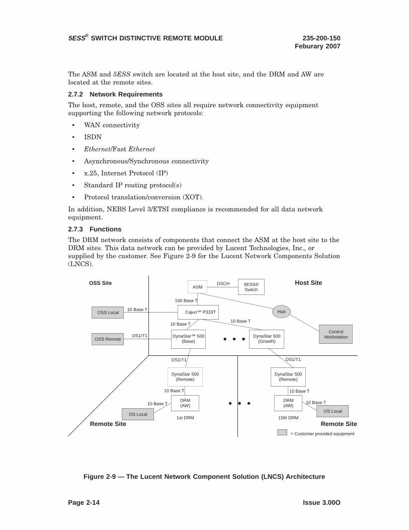
The ASM and 5ESS switch are located at the host site, and the DRM and AW arelocated at the remote sites.
2.7.2 Network Requirements
The host, remote, and the OSS sites all require network connectivity equipmentsupporting the following network protocols:
• WAN connectivity
• ISDN
• Ethernet/Fast Ethernet
• Asynchronous/Synchronous connectivity
• x.25, Internet Protocol (IP)
• Standard IP routing protocol(s)
• Protocol translation/conversion (XOT).
In addition, NEBS Level 3/ETSI compliance is recommended for all data networkequipment.
2.7.3 Functions
The DRM network consists of components that connect the ASM at the host site to theDRM sites. This data network can be provided by Lucent Technologies, Inc., orsupplied by the customer. See Figure 2-9 for the Lucent Network Components Solution(LNCS).
10 Base T10 Base T
10 Base T
DynaStar 500(Remote)
DynaStar 500(Remote)
DynaStar 500(Growth)
DynaStar 500(Base)
™
HubCajun™ P333T
ControlWorkstation
DRM(AW)
DRM(AW)
1st DRM 15th DRM
ASMDSCH
OSS Local
DS1/T1
5ESS®Switch
10 Base T10 Base T
DS1/T1 DS1/T1
OSS Remote
OS LocalOS Local
OSS Site Host Site
Remote Site Remote Site= Customer provided equipment
100 Base T
10 Base T10 Base T
Figure 2-9 — The Lucent Network Component Solution (LNCS) Architecture
5ESS® SWITCH DISTINCTIVE REMOTE MODULE 235-200-150Feburary 2007
Page 2-14 Issue 3.00O

The hardware components used in the Lucent Technologies Network Solution consistof:
• Cajun 6 P333T Ethernet Switch — a smart Ethernet switch
• DynaStar 500 7 — up to three routers at the host site, remote, and OSS sites.
2.7.3.1 Lucent Technologies Network Solution Documentation
Lucent Technologies Network Solution documentation referenced in this documentinclude:
• Avaya Cajun P333T Stackable Switch User’s Guide. For the latest copy go tohttp://support.avaya.com/elmodocs2/p330/P333T/p333t33ug.pdf
• Dynastar 100/100i/100e/5008 Multi-Service Switches Installation And UserGuide
For latest copy go to www.dynastarcom.com.
2.7.3.2 Component Functions
Each hardware component provides a unique function to the DRM Network.
2.7.3.2.1 The Smart Ethernet Switch
Unlike a hub, which is a passive device that broadcasts signals it receives to all otherdevices connected to it, the smart ethernet switch routes data it receives only to thecorrect destination.
In the LNCS, the Cajun P333T is the smart ethernet switch, and as such it:
• converts 100BaseT protocol to 10BaseT protocol
• allows multiple routers to interface with the single port on the QFE cardinstalled in the ASM.
2.7.3.2.2 The Routers
In the LNCS, there are two router options: A and C. Each has its own purpose.
Router option A is used in the LNCS to:
• supply up to 6 DS1s for routing data signals.
One DS1 is dedicated to a connection to operating systems used for billing,network management, and traffic measurement. The remaining 5 DS1s areconnected to DRM sites. Each DRM site is engineered with a DS1, therefore, upto 5 DRM sites may be connected to the first router.
The second and third routers installed are option C routers. These routers can supplyup to 6 DS1s for connection to DRM sites.
Each DRM site, has one option C router. This router converts between DS1 formatand 10 BaseT. The 10 BaseT connects to the rear of the Administrative Workstation(AW). Port 0 on a Quad Fast Ethernet card provides the interface for a Netra t 1120 orNetra 20. The onboard Broadcom Gigabit Ethernet port 2 provides the interface for a
6. Trademark of Avaya Communications.7. Trademark of DYMEC, Inc.8. Trademark of DYMEC, Inc.
235-200-150Feburary 2007
5ESS® SWITCH DISTINCTIVE REMOTE MODULE
Issue 3.00O Page 2-15

Netra 240. The DS1s are transported using a Primary Rate Interface (PRI) ISDNconnection. If the PRI is lost, a backup Basic Rate Interface (BRI) carries the datauntil the PRI is restored.
2.7.3.3 Hardware
The DRM network requires two distinct hardware configurations at the two types ofsites:
• the host site
• the remote DRM sites (up to 15)
2.7.3.3.1 Hardware Components at the Host Site
At the host site, the networking equipment can be installed in the same miscellaneouscabinet as the ASM. The Smart Ethernet Switch is a Cajun P333T. The routers areDynaStar9 500s. See Figure 2-10 for the configuration of the Lucent NCS. Router 00 isoption A, and Routers 01 and 02 are option C.
9. Trademark of DYMEC, Inc.
MFFU
Growth Router 02
(DynaStar 500 Option C)
Growth Router 01
(DynaStar 500 Option C)
Base Router 00
(DynaStar 500 Option A)
100 Base T 10 Base T
Ethernet™ Switch(Cajun P333T -48V)
ASM
Figure 2-10 — Host Site Hardware Components
5ESS® SWITCH DISTINCTIVE REMOTE MODULE 235-200-150Feburary 2007
Page 2-16 Issue 3.00O

2.7.3.3.2 Hardware Components at the DRM Site
At the DRM site, the AW is mounted in a miscellaneous cabinet. The DRM patchpanels and the high speed interfaces are mounted in a metal panel. Splitters, whichallow connections for the Remote MCC and Remote Console are mounted in a separatemetal panel. The DynaStar Option C is mounted in the same cabinet. See Figure 2-11for the DRM Site hardware of the Lucent NCS.
2.7.4 The Operational Support (OSS) Systems
Different operational support systems (OSSs) perform various support functions andare connected to the network in the different locations shown in Figure 2-12 .
MFFU
Remote Router #0(DynaStar 500 Option C)
Splitters
AW
DRM PatchPanel
Modem
Modem
MCC
Figure 2-11 — DRM Site Hardware Components
235-200-150Feburary 2007
5ESS® SWITCH DISTINCTIVE REMOTE MODULE
Issue 3.00O Page 2-17

The following Operating Systems support the DRM at either the host and remotesites:
• TNM — Total Network Management performs surveillance
• EADAS — Engineering and Administrative Data Acquisition System performstraffic analysis
• NFM — Network Fault Management
• AMATPS — AMA Teleprocessing (billing)
• AMADNS — Automatic Messaging Account Data Networking System (TCP/IPbilling)
• COT — Customer Originated Trace (modem connection to local law enforcementagency)
2.7.5 Network Component Maintenance Screens
The Cajun Smart Ethernet switch can be accessed by connecting a PC to the consoleport. The DynaStar 500 routers can be accessed through three different methods:
• connecting a laptop computer to port 6
Note: After initial configuration, the DynaStar 500 can use port 6 for otheroperations.
• a dial-up connection
• anywhere on the LAN to which the DynaStar 500 is connected.
ASM at Host SiteASM
RouterOption A
1 DS1
COTDRM Sites
AMADNS
DynaStar Option A Router atHost Site
TNM
EADAS
NFM
AMATPS
DRM Sites
Figure 2-12 — Operational Support Systems
5ESS® SWITCH DISTINCTIVE REMOTE MODULE 235-200-150Feburary 2007
Page 2-18 Issue 3.00O

2.8 Optional Local Terminal Interfaces
This section identifies and describes the various Input/Output (I/O) interfaces that areoptional for the DRM. These interfaces allow administrative and maintenancepersonnel and Operational Support Systems (OSSs) to communicate with the DRMfrom the DRM office. This section also describes the functions provided by the I/Ofacilities to assist the switch administrator.
Terminal devices are used by maintenance and administrative personnel for typinginput messages and displaying both input and output messages. Examples of terminaldevices are teletypewriters, cathode ray tube (CRT) terminals, and a Receive-OnlyPrinter (ROP). Data link interfaces are also provided to Operational Support Systems(OSSs) for additional administrative and/or maintenance support as needed.
Further information concerning the operations and functions provided by theseinterface facilities is provided in 235-190-1XX series of feature description documents.
Terminal devices are connected to the AW using the interface provided by the SerialAsynchronous Interface (SAI) card. The AW serial interface is shown in Figures 2-13 ,2-14 and 2-15.
It is recommended that MCC, ROP, and STLWS access is present at the DRM.
PO RT 7
PO RT 0
PO RT 1
PO RT 2
PO RT 3
PO RT 4
PO RT 5
PO RT 6
Asynchr onousPatch Panel
SAI-1(O ptional )
PO RT 7
PO RT 0
PO RT 1
PO RT 2
PO RT 3
PO RT 4
PO RT 5
PO RT 6
Asynchr onousPatch Panel
SAI-0
PCI1
PCI2
PCI3
PCI4
Figure 2-13 — Administrative Workstation Terminal Interface Connections ( Netra t1120)
235-200-150Feburary 2007
5ESS® SWITCH DISTINCTIVE REMOTE MODULE
Issue 3.00O Page 2-19

Console/LOMSerial
LEDs
AlarmsPort(DB 15)
PCI Slots
DC Power Connector B
HSSDCFC-ALConnector
RJ - 45Ethernet
4 USBPorts
Ultra SCSIPower SupplyLEDs
SCCCard
SerialPort A
SerialPort B
ParallelPort
DC Power Connector A
42
31
Figure 2-14 — Administrative Workstation Terminal Interface Connections ( Netra 20)
Figure 2-15 — Administrative Workstation Terminal Interface Connections ( Netra240)
5ESS® SWITCH DISTINCTIVE REMOTE MODULE 235-200-150Feburary 2007
Page 2-20 Issue 3.00O

2.9 Types of Terminal Interfaces and Operating Support Systems
This section will cover the following interfaces:
• Serial Interface
• High-Speed Interface
• Ethernet Interface
• Master Control Center (MCC)
• Receive-Only Printer (ROP)
• Supplemental Trunk Line Work Station (STLWS)
• Recent Change and Verify (RC/V)
• Automatic Message Accounting (AMA) Data Link
• SCANS Data Link.
• SCCS Data Link.
Refer to the documents listed in Table 2-4 for information about additional terminalinterfaces available at the DRM.
235-200-150Feburary 2007
5ESS® SWITCH DISTINCTIVE REMOTE MODULE
Issue 3.00O Page 2-21

Table 2-4 — Terminal Interface Devices
Name Description DocumentTRAFFPRT Local Traffic Measurements Channel 235-070-100A1
235-105-231OFFRECRPT On-line Office Record Print Channel is
used to print office record forms.235-118-2XX235-900-304
CALEASAS Electronic Surveillance Terminal 235-200-400235-200-410
CALEAPRT Electronic Surveillance Printer 235-200-400235-200-410
2.9.1 Serial Interface
The DRM uses a serial adapter card to interface multiple serial devices such asterminals and printers to the AW.
The serial card is equipped in the AW as follows:
• PCI slots (Netra 240) – PCI slot 1 is equipped with a Serial AsynchronousInterface (SAI) card that provides 8 serial ports for terminal and printerconnections. PCI slot 0 is equipped with a second SAI card that supports 8terminal and printer connections.
• PCI slots (Netra t 1120 and Netra 20) – PCI slot 2 is equipped with a SerialAsynchronous Interface (SAI) card that provides 8 serial ports for terminal andprinter connections. PCI slot 1 can be equipped with an optional second SAI cardthat supports 8 terminal and printer connections.
Figures 2-16, 2-17 and 2-18 provide illustrations of a Supplemental Trunk LineWorkstation (STLWS) and ROP connected to the AW system unit. While these figuresshow the STLWS attached to a specific port, a terminal device can occupy anyavailable non-reserved port. Tables 2-5 and 2-2 list the serial port assignments forterminal devices.
5ESS® SWITCH DISTINCTIVE REMOTE MODULE 235-200-150Feburary 2007
Page 2-22 Issue 3.00O
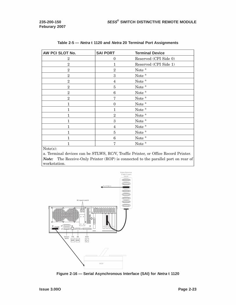
Table 2-5 — Netra t 1120 and Netra 20 Terminal Port Assignments
AW PCI SLOT No. SAI PORT Terminal Device2 0 Reserved (CPI Side 0)2 1 Reserved (CPI Side 1)2 2 Note a
2 3 Note a
2 4 Note a
2 5 Note a
2 6 Note a
2 7 Note a
1 0 Note a
1 1 Note a
1 2 Note a
1 3 Note a
1 4 Note a
1 5 Note a
1 6 Note a
1 7 Note a
Note(s):a. Terminal devices can be STLWS, RC/V, Traffic Printer, or Office Record Printer.Note: The Receive-Only Printer (ROP) is connected to the parallel port on rear ofworkstation.
PO RT 7
PO RT 0
PO RT 1
PO RT 2
PO RT 3
PO RT 4
PO RT 5
PO RT 6
Asynchr onousPatch Panel
SAI-0
To STLW S
RO P
PCI1
PCI2
PCI3
PCI4
Figure 2-16 — Serial Asynchronous Interface (SAI) for Netra t 1120
235-200-150Feburary 2007
5ESS® SWITCH DISTINCTIVE REMOTE MODULE
Issue 3.00O Page 2-23

PO RT 7
PO RT 0
PO RT 1
PO RT 2
PO RT 3
PO RT 4
PO RT 5
PO RT 6
AsynchronousPatch Panel
SAI-0
To STLWS
ParallelPort
ROP
Figure 2-17 — Serial Asynchronous Interface (SAI) for Netra 20
Figure 2-18 — Serial Asynchronous Interface (SAI) for Netra 240
5ESS® SWITCH DISTINCTIVE REMOTE MODULE 235-200-150Feburary 2007
Page 2-24 Issue 3.00O

2.9.2 High-Speed Interface
A High-Speed Interface (HSI) Controller is used to connect certain high speed terminaldevices to the AW.
The high-speed interface card is equipped in the AW as follows:
• PCI slots (Netra 240) – PCI slot 2 is equipped with a High Speed Interface (HSI)card that provides 4 ports for data link connections.
• PCI slots (Netra t 1120 and Netra 20) – PCI slot 3 is equipped with a High SpeedInterface (HSI) card that provides 4 ports for data link connections.
Figure 2-19, 2-20 and 2-21 provide illustrations of the HSI Controller High-SpeedInterface and its connection to the AW. Table 2-6 lists terminal devices that can beinterfaced using this controller.
01
M odem /DCE
M odem /DCE
To SCANS
To SCCS
H S I
To Optional OSS
Interface Converter
To AMA
321
M odem /DCE
M odem /DCE
M odem /DCE
Figure 2-19 — NETRA t 1120 Workstation High-Speed Interface to AW Connections
235-200-150Feburary 2007
5ESS® SWITCH DISTINCTIVE REMOTE MODULE
Issue 3.00O Page 2-25

PCI
1
OPTIONAL
PCI
2
PCI
3
PCI
4
01
3
Modem/
DCE
Modem/DCE
Modem/DCE
To SCANS
To AMA Modem/DCE
To SCCS
H S I
Modem/DCE
To Optional OSS
2
Interface Converter
Figure 2-20 — NETRA 20 Workstation High-Speed Interface to AW Connections
5ESS® SWITCH DISTINCTIVE REMOTE MODULE 235-200-150Feburary 2007
Page 2-26 Issue 3.00O

Figure 2-21 — NETRA 240 Workstation High-Speed Interface to AW Connections
235-200-150Feburary 2007
5ESS® SWITCH DISTINCTIVE REMOTE MODULE
Issue 3.00O Page 2-27

Table 2-6 — High-Speed Port Assignment
Controller Port Terminal Device0 SCANS Data Link1 AMA Data Link2 SCC Data Link3 EADAS Data Link
2.9.3 Quad Fast Ethernet (QFE) Interface ( Netra t 1120 and Netra 20)
The QFE card is used to interface up to four Ethernet networks. Figures 2-22 and 2-23illustrate the connections to the AW. Table 2-7 lists Ethernet networks that can beinterfaced using the QFE card.
PCI1
PCI2
PCI3
PCI4
QFE Card0
1
2
3
Figure 2-22 — Quad Fast Ethernet - Netra t 1120 Interface Connections
5ESS® SWITCH DISTINCTIVE REMOTE MODULE 235-200-150Feburary 2007
Page 2-28 Issue 3.00O

QFE Card0
1
2
3
234 1
Figure 2-23 — Quad Fast Ethernet - Netra 20 Interface Connections
235-200-150Feburary 2007
5ESS® SWITCH DISTINCTIVE REMOTE MODULE
Issue 3.00O Page 2-29

Table 2-7 — QFE Port Assignment
QFE Port Ethernet Networks0 ASM1 Not assigned2 Not assigned3 Not assigned
2.9.4 Broadcom Gigabit Ethernet (BGE) Interface ( Netra 240)
The onboard BGE ports are used to interface up to four Ethernet networks. Figure2-24 illustrates the connections to the AW. Table 2-8 lists Ethernet networks that areinterfaced using the BGE ports.
Figure 2-24 — BroadcomGigabit Ethernet — Netra 240 Interface Connections
5ESS® SWITCH DISTINCTIVE REMOTE MODULE 235-200-150Feburary 2007
Page 2-30 Issue 3.00O

Table 2-8 — BGE Port Assignments
BGE Port Ethernet Networks0 SM1 Not assigned2 ASM3 Not assigned
2.9.5 Master Control Center (MCC)
The Master Control Center (MCC) is the primary communication link between on sitemaintenance personnel and the DRM. A dual ported terminal is used to connect theSolaris Console to the A serial port and the MCC to the B serial port on the rear ofthe Netra t 1120 and Netra 20 AW. For a Netra 240 AW, the Solaris Console isconnected to the DB-9 serial port on the rear of the AW and the MCC is connected toserial port 6 on SAI-1.
Figures 2-25, 2-26 and 2-27 illustrate the MCC and Solaris Console cable connectionsfor the KS-22396 terminal.
MCC Terminal
Keyboard VideoAUX Port EIA Port
PCI1
PCI2
PCI3
PCI4
Figure 2-25 — KS-22396 MCC Interface to Administrative Workstation - Netra t 1120
235-200-150Feburary 2007
5ESS® SWITCH DISTINCTIVE REMOTE MODULE
Issue 3.00O Page 2-31

Figures 2-28, 2-29 and 2-30 illustrate the MCC and Solaris Console cable connectionsfor the KS-24697 terminal.
Keyboar d Video
AUX Port EIA Port
MCC Terminal
SerialPort B
SerialPort A
Figure 2-26 — KS-22396 MCC Interface to Administrative Workstation - Netra 20
Figure 2-27 — KS-22396 MCC Interface to Administrative Workstation - Netra 240
5ESS® SWITCH DISTINCTIVE REMOTE MODULE 235-200-150Feburary 2007
Page 2-32 Issue 3.00O
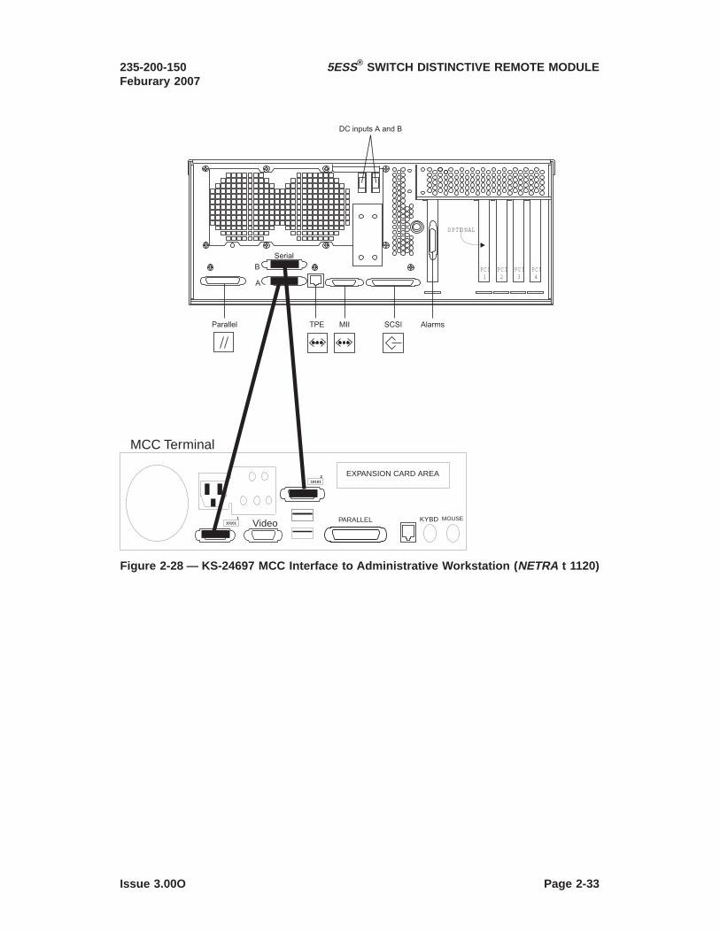
KYBD MOUSEVideo PARALLEL
EXPANSION CARD AREA
MCC Terminal
PCI1
O PTIO NAL
PCI2
PCI3
PCI4
110101
210101
Figure 2-28 — KS-24697 MCC Interface to Administrative Workstation ( NETRA t 1120)
235-200-150Feburary 2007
5ESS® SWITCH DISTINCTIVE REMOTE MODULE
Issue 3.00O Page 2-33

MCC Terminal
KYBD MOUSEVideo PARALLEL
EXPANSION CARD AREA
SerialPort B
SerialPort A
110101
210101
Figure 2-29 — KS-24697 MCC Interface to Administrative Workstation ( NETRA 20)
Figure 2-30 — KS-24697 MCC Interface to Administrative Workstation ( NETRA 240)
5ESS® SWITCH DISTINCTIVE REMOTE MODULE 235-200-150Feburary 2007
Page 2-34 Issue 3.00O

The MCC provides maintenance personnel with real-time system status indications,control and display capabilities, and input/output messages. Refer to Figure 2-31. TheMCC also provides manual emergency recovery capabilities, Recent Change functions,and the ability to request reports. The major components of the MCC consist of thefollowing:
• Video Display Terminal (VDT)
— The VDT display pages provide the status and control information needed toperform maintenance tasks. Maintenance requests are input using akeyboard. The terminal is also used to access Solaris UNIX10.
• Receive-Only Printer (ROP)
— The ROP provides a hardcopy of input and output messages, creating arecord for future reference. Traffic measurement data can also be directed tothe ROP.
2.9.5.1 Video Display
The optional local MCC video display terminal provides office maintenance personnelwith a means to interface with the DRM for system status indications, configurationcontrols, and human-machine interface messages. The MCC video display terminal isnot duplicated. For functional purposes, the video display terminal is divided into thefollowing units:
• Display
• Alphanumeric keyboard
• Numeric/function keypad.
The MCC (MTTY or MCRT) provides a split-screen effect (see Figure 2-31). The videodisplay has a general layout that consists of an identification line, a system summaryarea, a control and display page area, and an input message entry area.
10. Registered trademark in the United States and other countries licensed exclusively through X/OpenCompany Limited
235-200-150Feburary 2007
5ESS® SWITCH DISTINCTIVE REMOTE MODULE
Issue 3.00O Page 2-35

The identification line is present at all times and displays the office name, systemtype, and the current date and time.
The system status display provides an indication of the overall status of the office.This includes:
• Individual unit status
• Abnormal load conditions
• Significant controls in effect
• Alarms and other abnormalities.
The various conditions are shown in distinctive graphics and type faces.
The color video display at the MCC uses a variety of colors to indicate the status ofindividual units in the DRM.
The control and display area is provided to give the maintenance personnel theinterface necessary to operate and maintain the system. This area displaysinformation pertinent to the office and provides the controls for maintaining andoperating the system.
The various screen formats are referred to as control and display pages. Each controland display page shows the operating condition and possible input commands for eachsubsystem. An index page is provided to allow quick access to the display pages. Ablank page is displayed whenever other control and display information is notrequired. For additional information on the MCC display pages, see 235-105-110,5ESS Switch System Maintenance Requirements and Tools. Figure 2-32 shows atypical MCC display page.
Figure 2-31 — MCC Page Display Design
5ESS® SWITCH DISTINCTIVE REMOTE MODULE 235-200-150Feburary 2007
Page 2-36 Issue 3.00O

The bottom two lines of the video display are used for message entry. This areadisplays the input messages from the MCC keyboard.
2.9.5.2 Emergency Action Interface (EAI)
The primary function of the EAI is to provide manual recovery capabilities duringperiods of system emergency. This interface enables configuring a working systemwhen normal recovery procedures prove inadequate. The emergency page has a menuof control and initialization functions that can be forced on the system. Figure 2-33shows a typical EAI display page.
Figure 2-32 — Typical MCC Display Page
235-200-150Feburary 2007
5ESS® SWITCH DISTINCTIVE REMOTE MODULE
Issue 3.00O Page 2-37

Each function is defined and input by a 2-digit command code. The codes are shownwith their associated functions on the display. These functions can be used to do thefollowing:
• Recover from duplex-processor failures.
• Disable the sanity timer.
• Disable hardware checks.
• Boot the system from other devices.
The conventions used for displaying data and selecting functions are similar to thoseused by other control and display pages. Due to the crucial functions provided,maintenance personnel must be familiar with these commands and their use.
Note: There is a sequence of EAI commands that can reduce downtime duringperiods of system emergency. This command sequence, the 42;9;54 and 42;9;50 pokes,executes a Full Office Initialization (FOI) with full pump of the switching modules andCMPs in two parts. The 42;9;54 poke must be entered first and causes a fullinitialization of the AM. When the AM has completed the initialization process, the42;9;50 poke must be entered next within 30 minutes of the entry of the 42;9;54. The42;9;50 poke performs a full initialization with full pump of the switching module. Ifthe 42;9;50 poke is entered before the 42;9;54 or after the 30-minute window, theinitialization of the switching module does not occur. Refer to 235-105-250, 5ESSSwitch System Recovery Manual, for detailed procedures on the use of this pokesequence and for information and procedures on other FOI variations.
An in-progress FOI can be cancelled by executing pokes 42;q;50 or 42;Q;50. Theexecution of these pokes results in the cancellation of the full initialization with orwithout pump. The pending initialization of the switching module can be cancelled by
MCRT7
Figure 2-33 — Emergency Action Interface (EAI) Page
5ESS® SWITCH DISTINCTIVE REMOTE MODULE 235-200-150Feburary 2007
Page 2-38 Issue 3.00O

input command INIT:SM=a,NOINIT; . See 235-600-700, Input Messages Manual, foradditional information on this command.
2.9.5.2.1 Emergency Action Interface (EAI) Validity
After requesting the emergency action display page by depressing the EMER DISPfunction key, the video terminal digit indicator must be checked to ensure a validdisplay. The video terminal indicator is located in the upper center portion of thedisplay (Figure 2-33). The video terminal digit indicator consists of the maintenanceteletypewriter (MTTY) or maintenance cathode ray tube/terminal (MCRT) followed bya numeric digit displayed in dynamic text. The digit is increased every 2 seconds. Ifthis indicator is not displayed and is not increasing, the entire display is invalid.
Once the validity of the display is determined, other indicators are used to qualify EAIand emergency functions. Table 2-9 summarizes these indicators.
Note: The rest of the indicators on the display are valid only for EAIs indicating AllSeems Well (ASW).
2.9.5.2.2 Emergency Action Interface Indicator Area
The EAI indicators reflect the progress of the emergency action. The emergency actionis progressing successfully if the ASW indication is present (Figure 2-33).
The Control Unit (CU) status area is located at the upper left portion of the EAI pagedisplay (Figure 2-33). This area informs the maintenance personnel which of the CUsis active and which is on- or off-line. The term CU refers to the control unit or the AW.
At the upper right portion of the EAI page display is the Processor Recovery Message(PRM) area (Figure 2-33). The PRMs display the systems coded failure/successrecovery information. The PRMs change continuously during an initialization,reflecting the current state.
235-200-150Feburary 2007
5ESS® SWITCH DISTINCTIVE REMOTE MODULE
Issue 3.00O Page 2-39

Table 2-9 — Emergency Action Indications and Qualifiers
INDICATIONS MEANINGEAI INDICATIONS MEANING WHEN DISPLAYED IN REVERSE VIDEOASW (1) 3B21 emulator is communicating with EAI.
(2) EAI reports all seem well (ASW).ERR (1) 3B21 emulator is communicating with the EAI.
(2) EAI reports internal EAI problem.OOS (1) 3B21 emulator is not communicating with the EAI.
(2) Displayed EAI status is unreliable.CU INDICATIONS MEANING WHEN DISPLAYED IN REVERSE VIDEOACT Control unit (CU) Software is on-line (active).FONL Emergency action has forced hardware on-line.FOFL Emergency action has forced hardware off-line.RUN CU is running under software release control.RCVRY CU has begun recovery.SET Associated function is set.INH Associated function is inhibited.PRM DIGITS MEANING OF THE DIGITSrrrr rrrr rrrr rrrr Indicates the Processor Recovery Message (PRM).ss ss Indicates the emergency action status at the time the PRM
was received.nn Indicates the low-priority PRM state at the time the PRM
was received.PRM TEXTDISPLAYED
MEANING WHEN IN PARTICULAR TEXT
rrrr rrrr rrrr rrrr ss ssnn
(bold reverse video)
Trapped failure PRM.
rrrr rrrr rrrr rrrr ss ssnn
(dynamic text)
Last PRM received from the EAI.
2.9.5.2.3 Emergency Action Interface (EAI) Menu
Emergency functions are entered by typing the appropriate 2-digit command code andexecuting it. Table 2-10 provides a list of the EAI commands with a description of
5ESS® SWITCH DISTINCTIVE REMOTE MODULE 235-200-150Feburary 2007
Page 2-40 Issue 3.00O

their actions. For more details of how to use these functions, refer to 235-105-250,5ESS Switch System Recovery. The carriage return is used to execute emergencyfunctions.
The menu commands can be grouped into the following categories:
• Commands 14 and 15: These commands have a direct and immediate effect onthe system. Some commands force the AM into a particular configuration andsome release a forced configuration.
• Commands 20 through 43: These commands are preparation commands thatspecify certain conditions prior to a system initialization. These conditions do nottake effect until an initialization command is given.
• Commands 50 through 58: These are the initialization commands. Thesecommands cause the conditions that were specified previously with commands 20through 43 to take effect.
• Command 59: This command stops the 3B21 emulator, thus stopping the AM.
Note: This command should NOT be executed unless under the direction ofCustomer Technical Support.
The severity of the initialization increases with the command number (command 54has the greatest impact). The system can automatically trigger commands 50 through53 during an initialization.
Command 54 can only be triggered manually and causes an AM initialization. Thistakes these processors completely off-line.
Command 55 is normally required during the initial installation interval or when aninitialization from tape is required due to a massive corruption of disk data. Duringthis tape load, the system is off-line and call processing is disabled for a considerableperiod of time.
The 51 through 58 commands when entered on the command line cause the system toimmediately enter an emergency action mode.
Once the emergency action has completed, the system is restored (automatically) to astable state and call processing resumes. The EAI page display disappears and theMCC Page Display 111/112, AM Peripherals, is automatically displayed.
Caution: Commands from the EAI page display should only be used underthe direction of your technical assistance group. Improper use of thecommands on the EAI page can have a very negative impact on the integrity ofthe system.
Each command executed is acknowledged either OK or NG. This acknowledgmentappears adjacent to the command entry area in the top left line of the display. Afterentering a command, the input and response are displayed until the next character istyped. Errors may be erased a character at a time by pressing the backspace key or bypressing Ctrl h.
235-200-150Feburary 2007
5ESS® SWITCH DISTINCTIVE REMOTE MODULE
Issue 3.00O Page 2-41

Table 2-10 — Emergency Action Interface (EAI) Maintenance Commands
COMMAND DESCRIPTION14 Clears all of the following which may be in effect: forces on- or
off-line, sets on primary or secondary disk and timer inhibits.15 Used together with the application parameters (1, 2, or 3) to
produce three levels of craft initialization.20 Inhibits automatic processor recovery disk unit selection and forces
both processors to access their primary disk units on a boot.21 Removes force on primary disk unit select.22 Same as 20, except forces the processors to access their secondary
disks.23 Removes force on secondary unit select.24 Inhibits the sanity timer from expiring and initiating automatic
recovery action.25 Removes the sanity timer inhibit.26 Releases any trapped failure Processor Recovery Messages (PRM)
and causes the next failure PRM to be displayed in reverse videoand to remain displayed until released.
27 Releases any trapped failure PRMs and allows further PRMs to bedisplayed.
30 a Forces the processor to initialize from the backup root file system.31 Allows the processor to initialize from the primary root file system.32 Forces the processor to initialize only the UNIX RTR (Real-Time
Reliable) operating system. The application software is notinitialized.
33 Allows the processor to initialize both the UNIX RTR operatingsystem and the application software.
34 Inhibits hardware checks from initiating automatic recovery action.35 Allows the hardware checks to initiate automatic recovery action.36 Inhibits software checks from initiating automatic recovery action.37 Allows software checks to initiate automatic recovery action.38 Inhibits error interrupts.39 Allows error interrupts.42 Allows the setting of a parameter which is made available to
application software.43 Clears the application parameter.50 Signals the application software to initialize.51b Forces initialization of the UNIX RTR operating system (level 1
initialization).52 Reloads the UNIX RTR operating system from disk (level 2
initialization).53 Same as 52, plus reloads Equipment Configuration Data (level 3
initialization).54 Same as 53, plus clears the memory (level 4 initialization).
5ESS® SWITCH DISTINCTIVE REMOTE MODULE 235-200-150Feburary 2007
See note(s) at end of table.
Page 2-42 Issue 3.00O

Table 2-10 — Emergency Action Interface (EAI) Maintenance Commands (Contd)
COMMAND DESCRIPTION55c Loads selected disk from tape unit 0.57 Same as 54 plus reboots the 3B21 emulator.58 Same as 57 plus reboots Solaris System V Release 4 OS59 Stops the 3B21 emulator, thus stopping the AM.Note(s):a. Commands 30 through 43 generate the next state of the maintenance
teletypewriter (MTTY) peripheral control information which is sent to theprocessor the next time commands 50 through 55 are executed.
b. Commands 51 through 55, in addition to the description given, cause the currentnext state information to be sent to the processor.
c. Command 55 requires a disk unit to be selected (commands 20 or 22).
2.9.5.3 MCC Page 111/112 - AM, AM Peripherals
The purpose of the 111/112 display page is to report the status of the AW (shown asAM on the screen) and its peripherals. The AW peripherals are the MHDs, MT, MTTY,ROP and the link to the switching module.
Figure 2-34 is an example of the DRM version of the 111/112 display page. Note thatall restore pokes are executed with the unconditional (UCL) option.
Figure 2-34 — MCC Display Page 111,112 AM, AM Peripherals
235-200-150Feburary 2007
5ESS® SWITCH DISTINCTIVE REMOTE MODULE
Issue 3.00O Page 2-43

An off-normal condition on this page will cause the AM or AM PERPH indictor at thetop of the screen to backlight. In this case, the appropriate alarm level (CRITICAL,MAJOR, MINOR) will also backlight.
2.9.5.3.1 Abbreviations
OOS Out Of Service
ACT Active
MTTY Maintenance Teletypewriter
ROP Receive-Only Printer
UCL Unconditional
2.9.5.3.2 Commands
The 111/112 page provides command to remove, restore, diagnose, and switch thevarious units. Also, output commands are available for out-of-service and diagnosticlistings.
CMD RESULT20X MHD X is removed (RMV: MHD=X)210 MT 0 is removed (RMV:MT=0)250 MTTY 0 is removed (RMV:MTTY=0)260 ROP 0 is removed (RMV:ROP=0)30X,UCL MHD X is unconditionally restored (RST:MHD=X,UCL)310,UCL MT 0 is unconditionally restored (RST:MT=0,UCL)350,UCL MTTY 0 is unconditionally restored (RST:MTTY=0,UCL)360,UCL ROP 0 is unconditionally restored (RST:ROP=0,UCL)404 OOS units are listed at ROP (OP:CFGSTAT, OOS)
2.9.5.4 MCC Page 113 - Operations Systems Links
The 113 display page provides a listing of Operations Systems links and their status.
5ESS® SWITCH DISTINCTIVE REMOTE MODULE 235-200-150Feburary 2007
Page 2-44 Issue 3.00O

Figure 2-35 shows an example of display page 113 for the DRM.
The Software Change Administration and Notifications System 2 (SCANS2) is used totransmit Software Updates (SUs) to both the office and the Switching Control Center(SCC) in previous 5ESS releases where Lucent Electronic Delivery (LED) is notavailable.
The Automatic Message Accounting Data Link (AMADL) connects the AutomaticMessage Accounting Teleprocessing System (AMATPS) with a Revenue AccountingOffice (RAO) to assemble billing data locally at the DRM in older 5ESS releases whereAMADNS is not available.
The SCC connects the office to the SCC System (SCCS) which monitors andadministers the office.
The EADAS connects the office to the EADAS system which collects engineering andadministrative data previous 5ESS releases.
2.9.5.5 MCC Page 116 - Miscellaneous Status
The 116 display page provides a status display for various units/activities which donot fall under any other grouping. For DRM configurations, miscellaneous alarms areshown on display page 1400. Figure 2-36 shows the 116 display.
Figure 2-35 — MCC Display Page 113
235-200-150Feburary 2007
5ESS® SWITCH DISTINCTIVE REMOTE MODULE
Issue 3.00O Page 2-45

The CALL MONITOR indicator shows whether the Call Monitor is inhibited orallowed. Entering the command 601 generates the message INH:CALLMON which willinhibit the monitor from making test calls and performing call completion analysis.This also clears the monitor’s history data. The command 701 generates the messageALW:CALLMON which allows the monitor to start the cycle of making test calls andperforming call completion analysis. Command 801 generates the messageRTR:CALLMON,ALARM which retires the alarm indicator in the Call Monitor box.Command 901 generates the message OP:CALLMON which generates the OPCALLMON PAST 15 MINUTE REPORT on the ROP.
The indicator GENERIC RETROFIT will backlight and change to GENERICRETROFIT ACTIVE when software release (generic) retrofit is in progress.
The indicator ODD EVOLUTION will backlight and change to ODD EVOL ACT whenODD Evolution is in progress. ODD Evolution is initiated by the commandBKUP:ODD,ODDEVOL and stays in effect until the actual software release cut-overtakes place.
The indicator ODD WARNING will backlight when either the amount of ODD spacebeing used has exceeded the engineering recommendations for the AM or theautomatic relation engineering reorganization process has failed on one or morerelations in the AM. Entering the command 902 generates the input messageOP:ODDWARN,AM which will generate the OP ODDWARN output message on theROP.
The RCLOG WARNING indicator will backlight when the recent change log reaches80 percent full. Enter poke 903 to output the recent change log status. To clear aRCLOG WARNING, perform Backup ODD.
The RCLOG WARNING indicator is provided on the 116 page. A major alarm occursand this indicator is backlighted when the RC log files approach full capacity. The 903poke provides additional information.
SYS EMER CRITICAL MAJOR MINOR CKT LIM SYS NORM
OVERLOAD SYS INH AM AM PERPH OS LINKS SM MISC
CMD< 116 - MISCELLANEOUS
601 CALL MONITOR CALL MONITOR SM FILE NORMAL
MTIB SEE PAGE 127
INHIBIT ALARM
CUTOVER
SEE PAGE 197
701 CALL MONITOR
BWM AUTOMATION
GENERIC RETROFIT SEE PAGE 1941
801 CALL MONITOR ALM ODD EVOLUTION
ODD WARNING RCLOG WARNING
901 CALL MONITOR RC BACKUP NORMAL
902 ODD WARNING
903 RCLOG WARNING
INHIBIT
ALLOW
RETIRE
OUTPUT
Figure 2-36 — Miscellaneous Status Summary - MCC Display Page 116
5ESS® SWITCH DISTINCTIVE REMOTE MODULE 235-200-150Feburary 2007
Page 2-46 Issue 3.00O

The RC BACKUP indicator normally shows NORMAL on the right part of theindicator. If RC Backup fails in the AM, the text NORMAL changes to FAILURE andthe entire indicator backlights.
The next indicator, MTIB, will backlight if an off-normal condition exists on the MTIBdisplay. Enter command 127 for further details.
In the CUTOVER indicator, the word ACTIVE will backlight if an off-normal conditionexists on the CUTOVER display (cut-over enabled, for example). Further informationcan be found on display 197 - CUTOVER.
The indicator BWM AUTOMATION will backlight when the BWM automation processis halted for any reason.
The indicator SM FILE shows NORMAL (in the right portion of the indicator) whilethe system is operating normally. If the UPD:HSCHK audit finds hashsum errors onany of the SM/SM peripheral, the indicator will backlight and NORMAL changes toHASHERR. For more information, analyze the last output message from theUPD:HSCHK command (on the ROP) or request a summary report of the errors viathe UPD:HSCHK,REPT option of the command. The indicator is cleared when thecause if the disk hashsum error has been corrected and the UPD:HSCHK audit isre-run.
2.9.5.5.1 Abbreviations
HASHERR Hashsum Error
MTIB Metallic Test Interface Bus
2.9.5.5.2 Commands
Commands are provided to inhibit and allow the call monitor, output the past15-minute interval history for the call monitor, retire a call monitor alarm or outputODD WARNING information.
Also, all available displays can be accessed from the 116 display page.
CMD RESULT601 Call Monitor is inhibited (INH:CALLMON)701 Call Monitor is allowed (ALW:CALLMON)801 Call Monitor alarm is retired (RTR:CALLMON,ALARM)901 Call Monitor history is output (OP:CALLMON)902 ODD WARNING information is output (OP:ODDWARN,AM)903 RCLOG WARNING information is output (OP:RCSTAT,AM)
2.9.5.6 MCC Page 124 - DCI/ASM Status
The purpose of the 124 page on the DRM is to provide information about the ASM andthe DCI link. The DCI link for a DRM is a Virtual DCI (VDCI) link over the networkconnection to the ASM. The DRM 124 page contains the same information as that on a3B21 with one exception, only a 3B21 can have a connection to the ASM console port.Therefore, the bottom box on the 124 page (ASMLNK) which displays the status of theconsole port will not display on the 124 page on a DRM. Figure 2-37 shows the 124page.
235-200-150Feburary 2007
5ESS® SWITCH DISTINCTIVE REMOTE MODULE
Issue 3.00O Page 2-47

2.9.5.7 MCC Page 1190 - MCTSI Status
The purpose of the 1190 page display is to show status and provide maintenancecommands for the Module Controller/Time Slot Interchanger (MCTSI) and theexternal timing references. Figure 2-38 shows the 1190 page.
When an off-normal condition occurs, the indicator for the condition backlights. OnPage 1010,X, the MCTSI indicator backlights. On Page 114, the indicator for theswitching module backlights; and on the appropriate 141, 142, 143, or 144 page, theindicator for the switching module backlights, and a phrase describing the problem iswritten, unless a more critical condition exists. In the SUMMARY STATUS AREA, theswitching module critical indicator and the alarm level (CRITICAL, MAJOR, orMINOR), if applicable, are backlighted.
SYS EMER CRITICAL MAJOR MINOR BLDG/PWR BLDG INH CKT LIN SYS NORM
OVERLOAD SYS INH AM AM PERPH OS LINKS SM CM MISC
CMD< 124 - DCI/ASM STATUS PAGE
REMOVE: 20X DCI-0
ACT
RESTORE: 30X
DIAGNOSE: 50X
ASM-0 ACT
Figure 2-37 — MCC Display Page 124
5ESS® SWITCH DISTINCTIVE REMOTE MODULE 235-200-150Feburary 2007
Page 2-48 Issue 3.00O

The MCTSI status data is stored in the switching module.
2.9.5.7.1 Commands
Commands are given to remove, restore, and diagnose the MCTSI or external timingreferences and to switch the MCTSI or to force active the MCTSI. Any availablepaging commands can be entered from the 1190 page.
CMD RESULT20X MCTSI X is removed. (RMV:MCTSI=SM#-X) [,UCL]23XY MCTSI X REF Y is removed (RMV:SMREF=SM#-X-Y)30X MCTSI X is restored. (RST:MCTSI=SM#-X) [,UCL]
[,STBY]33XY MCTSI X REF Y is restored. (RST:SMREF=SM#-X-Y)50X MCTSI X is diagnosed. (DGN:MCTSI=SM#-X,RAW,TLP)
[,UCL] [,GROW][,RPT] Test is repeated 32,767times.[,RPT=a] The "a" is the number oftimes the test is to be repeated(1-32,767).[,PH=b|b&&c] The "b" is thediagnostic phase or "b&&c" is therange of phases to be performed.
63XY MCTSI X REF Y is inhibited. INH:HDWCHK,SMREF=SM#-X-Y73XY MCTSI X REF Y is allowed. ALW:HDWCHK,SMREF=SM#-X-Y40x MCTSI X is forced active.
SYS EMER CRITICAL MAJOR MINOR CKT LIM SYS NORM
OVERLOAD SYS INH AM AM PERPH OS LINKS SM MISC
CMD< 1190 - SM 050 DRM MCTSI
20X MCTSI
23XY MCTSI X REF Y NORMAL
SITE 000
30X MCTSI X
33XY MCTSI X REF Y
50X MCTSI X 63XX MCTSI X REF Y
MCTSI 0 MCTSI 1
ACT STBY
403 MCTSI 73XY MCTSI X REF Y
REF 0 REF 1 REF 0 REF 1
40X SET MCTSI X ACT STBY STBY STBY
402 CLR FORCE
REMOVE SM 050 STAT
RESTORE
DIAGNOSE INHIBIT
SWITCH ALLOW
FORCE ACTIVE
Figure 2-38 — MCC Display Page 1190
235-200-150Feburary 2007
5ESS® SWITCH DISTINCTIVE REMOTE MODULE
Issue 3.00O Page 2-49

CMD RESULT402 MCTSI forces cleared.403 MCTSI is switched. (SW:MCTSI=SM#)
2.9.5.8 MCC Page 1400 - Switching Module BLDG/PWR Alarm Status
The purpose of the 1400,X page is to display all building/power alarm status andassignment and the alarm retire mode. It also provides inhibit/allow controls forbuilding alarms.
The Alarm Status Unit (ASU) provides audible and visual indication of the officealarms with LEDs for the alarm levels (critical, major, minor). There is an AlarmRetire key at the ASU which retires the audible alarms and clears the alarm levelLEDs at the ASU with no effect on the SSA of the terminal.
A normal alarm indicator is displayed in normal video (white on black). Figure 2-39provides a view of the 1400 page.
Building alarms 02-31 and their alarm levels are office assignable. Doors, windows,humidity, etc. are types of applications. The alarm level and text in these indicatorsare initially filled in using RC/V. Once these indicators are filled in, they are protectedfrom loss if the system is booted.
2.9.5.8.1 Commands
The following commands are available to inhibit, allow, or retire alarms.
Figure 2-39 — MCC Display Page 1400
5ESS® SWITCH DISTINCTIVE REMOTE MODULE 235-200-150Feburary 2007
Page 2-50 Issue 3.00O

CMD RESULT6XX Inhibit Alarm XX7XX Allow Alarm XX800 Auto Alarm Retire801 Manual Alarm Retire
2.9.5.9 MCC Keyboard
The local DRM MCC keyboard keys are used in a normal fashion to enter numericcodes, input messages, and alphanumeric responses to the system. Certain keys areused for administration as explained in the remainder of this section.
The MCC uses five function keys. When one of these keys (see Figure 2-40) isdepressed, the system performs the corresponding function. The keys are as follows:
• ALM RLS: alarm release
• CMD/MSG: input command or input message
• NORM DISP: normal display
• EMER DISP: emergency action display
• Control + ENTER (not the return key): UNIX mode key (switches between DRMmode and UNIX mode on the MCC).
Figure 2-40 — MCC Video Terminal With Function Keys
235-200-150Feburary 2007
5ESS® SWITCH DISTINCTIVE REMOTE MODULE
Issue 3.00O Page 2-51

2.9.5.9.1 Alarm Release Function Key
There are two system alarm release modes: automatic alarm release and manualalarm release. If the system is in the automatic alarm release mode, the audible alarmand the flashing alarm conditions are released 8 seconds after initialization. If thesystem is in the manual alarm release mode, the audible alarm and flashing alarmconditions are released by depressing the ALM RLS function key on the video terminalkeyboard. Minor audible alarms are retired after 8 seconds in either mode. Releasedalarms and controls in effect remain in the alarm condition until the system has beenrestored to normal operating condition. The alarm release mode is changed via amaintenance command available on MCC display page 1400, or an input message.Refer to 235-105-110, 5ESS Switch System Maintenance Requirements and Tools, for acomplete listing of MCC status indicators and their meanings.
2.9.5.9.2 Input Command Or Message Function Key
The command/message (CMD/MSG) function key configures the MCC to accept eitherinput CMDs or input MSGs. The key acts as a toggle and allows input in one mode orthe other. Personnel may switch between either mode after acknowledgment of thepreviously entered message. Any unexecuted data in either area is lost if a switch ismade before an acknowledgment is received. The position of the cursor on the videodisplay indicates which input mode the MCC is in. The cursor resides in the inputmessage line area while in the MSG mode. If the MCC is in the CMD mode, thecursor resides at the CMD entry area (at the top left of the control and display area).Whenever the display is brought on line or a new page is selected, the input mode willremain unchanged.
2.9.5.9.3 Normal Display Function Key
The NORM DISP function key places a page controlled from the emulated AM on thedisplay screen. The page displayed will be the previously displayed page. Depressingthe NORM DISP function key again will redraw a clean display without aborting anyprocesses in progress.
2.9.5.9.4 Emergency Action Display Function Key
The EMER DISP function key enables the emergency action mode and displays theEAI page on the screen. See “Emergency Action Interface (EAI),” Section 2.9.5.2. Thispage is used during a system emergency for system recovery functions. To exit the EAIpage, press the NORM DISP key.
2.9.5.9.5 Control + Enter Key
Press the Control + Enter key to switch between the UNIX system mode and the DRMmode on the MCC display. The Enter key is located on the right side of the keyboardin the numeric keypad section. Do not confuse the Enter key with the Return key onthe main keyboard.
2.9.5.9.6 Data Entry Functions
Most other keyboard keys are used in a normal fashion to enter numeric codes, inputmessages, and alphanumeric responses to the system.
5ESS® SWITCH DISTINCTIVE REMOTE MODULE 235-200-150Feburary 2007
Page 2-52 Issue 3.00O

2.9.6 Receive-Only Printer (ROP)
The ROP provides the local office personnel with a means for obtaining a hardcopyprintout of system messages. This printout provides a permanent copy of messages forfuture reference. Since the message may not always be displayed on the MCC videodisplay, the printout may be the only copy of the message available to themaintenance personnel.
Every message the system generates is not necessarily printed at the ROP. Somemessages are logged, while some are only printed at the originating terminal inresponse to an input message. Because of the large number of output messages thatmay be generated by the system, controls are available to the maintenance personnelto limit the volume of messages printed. For further information on 5ESS switchoutput messages, see 235-600-750, Output Messages Manual.
The ROP is connected to the following AW ports:
• Parallel port on the rear of a Netra t 1120 and Netra 20
• SAI-1 serial port 7 on a Netra 240
Figures 2-41, 2-42 and 2-43 illustrate the optional interface connection between theROP and the AW.
235-200-150Feburary 2007
5ESS® SWITCH DISTINCTIVE REMOTE MODULE
Issue 3.00O Page 2-53

PO RT 7
PO RT 0
PO RT 1
PO RT 2
PO RT 3
PO RT 4
PO RT 5
PO RT 6
Asynchr onousPatch Panel
SAI-0
To STLW S
RO P
PCI1
PCI2
PCI3
PCI4
Figure 2-41 — STLWS and ROP Interface - Netra t 1120
5ESS® SWITCH DISTINCTIVE REMOTE MODULE 235-200-150Feburary 2007
Page 2-54 Issue 3.00O

Note: To modify ROP settings, refer to the Receive-Only Printer (ROP) SettingsProcedure in Section 11 of the 235-105-210, Routine Operations and MaintenanceProcedures manual.
PO RT 7
PO RT 0
PO RT 1
PO RT 2
PO RT 3
PO RT 4
PO RT 5
PO RT 6
AsynchronousPatch Panel
SAI-0
To STLWS
ParallelPort
ROP
Figure 2-42 — STLWS and ROP Interface - Netra 20
Figure 2-43 — STLWS and ROP Interface - Netra 240
235-200-150Feburary 2007
5ESS® SWITCH DISTINCTIVE REMOTE MODULE
Issue 3.00O Page 2-55

2.9.7 Supplemental Trunk and Line Work Station (STLWS)
The Supplementary Trunk and Line Work Station (STLWS) is an optional localinteractive menu interface used to test, monitor, or measure trunks and lines. TheSTLWS terminal is a Display Administration Process (DAP) type terminal. This meansthe office personnel can perform the same functions or commands from the STLWSthat can be performed from the MCC, with the exception of being able to access theEAI page display.
Some of the operations that may be performed using the STLWS are as follows:
• Controlling lines and trunks being tested
• Monitoring a short circuit
• Measuring/sending frequencies
• Making continuous metallic measurements
• Providing remove or restore commands used for testing.
2.9.8 Recent Change (RC/V)
The RC/V system is a function that allows maintenance personnel access to a DRM’sdatabase. A DRM’s database is a stand-alone ODD that is separate from the databaseat the Host. The RC/V system is used to add to, delete from, update, or verify a DRM’sdatabase. A stand-alone RC/V subsystem is provided at the DRM. Therefore,Operational Support System (OSS) interfaces are not required to use RC/Vcapabilities. The stand-alone RC/V enables office and/or maintenance personnel tochange or verify the DRM’s database using video displays and menu selection via acut-through to the DRM through the ASM as explained in the 235-200-145, 5ESSSwitch OneLink Manager Administrative Services Module (ASM) User’s Guide. Fordetailed information applicable to RC/V procedures, see 235-118-XXX (where XXX =the document number associated to the applicable software release), 5ESS SwitchRecent Change Manual, 235-000-000, 5ESS Switch Division 235 Numerical Index, andassociated documents.
Recent Change and Verify (RC/V) is a process used to modify each DRM’s OfficeDependent Data (ODD). RC/V:
• isolates the administrative process from the actual modification-of-the-data-baseprocess
• provides a user-friendly view of the database.
The RC/V system is composed of many user interfaces which allow personnel to modifyor verify the contents of the ODD. The RC/V facility currently provides the followinginterfaces:
• RC/V Menu Interface - immediate and batch release
• RC/V Text Interface - immediate and batch release
• Office Records (OFR)
• Recent Change Operations Systems (RCOS) Interface
• Facility Management (FM).
5ESS® SWITCH DISTINCTIVE REMOTE MODULE 235-200-150Feburary 2007
Page 2-56 Issue 3.00O

2.9.9 SCANS Data Link
Although all software updates are distributed from the ASM via the FeatureDeployment on ASM feature, the DRM can support a local SCANS data link. See235–200–145, 5ESS Switch OneLink Manager™Administrative Services (ASM)User’s Guide for more information.
The Software Change Administration and Notification System (SCANS) is a softwaresupport package provided by Lucent technologies. SCANS provides the followingservices:
• Distributing emergency software fixes
• Distributing bulletins, or information about generic software fixes
• Distributing Software Updates (SUs)
• Introducing new software features.
Figures 2-44, 2-45 and 2-46 show the interface connection of the SCANS terminal tothe AW.
PCI1
PCI2
PCI3
PCI4
01
2 3
Interface Conver ter
M odem /DCE
M odem /DCE
M odem /DCE
M odem /DCE
To SCANS
To AM A
To SCCS
H S I
M odem /DCE
To EADAS
Figure 2-44 — SCANS/AMA/SCCS/Optional OSS Interface - Netra t 1120
235-200-150Feburary 2007
5ESS® SWITCH DISTINCTIVE REMOTE MODULE
Issue 3.00O Page 2-57

01
M odem /DCE
M odem /DCE
To SCANS
To SCCS
H S I
To Optional OSS
Interface Converter
To AMA
321
M odem /DCE
M odem /DCE
M odem /DCE
Figure 2-45 — SCANS/AMA/SCCS/Optional OSS Interface - Netra 20
5ESS® SWITCH DISTINCTIVE REMOTE MODULE 235-200-150Feburary 2007
Page 2-58 Issue 3.00O

2.9.10 Automatic Message Accounting (AMA) Data Link
Billing activities are performed at the ASM via tapes, a datalink, or the AMADNSapplication (if purchased). For the AMADNS application, a local AMA data link,AMATPS, can be connected at the DRM. The Billing and Data Systems (BILLDATS11)is a software system whereby a host collector receives billing data from the DRM.Figures 2-44, 2-45 and 2-46 show the AMA data link which provides the hardwareinterface requirements for the BILLDATS system. For more information about theAMA data link, see 235-070-100, 5ESS Switch Administration and Engineering
11. Registered trademark of AT&T Corp.
Figure 2-46 — SCANS/AMA/SCCS/Optional OSS Interface - Netra 240
235-200-150Feburary 2007
5ESS® SWITCH DISTINCTIVE REMOTE MODULE
Issue 3.00O Page 2-59

Guidelines and 235-190-300, 5ESS Switch Billing Features and Specifications. (See235-200-145, 5ESS Switch OneLink Manager Administrative Services Module (ASM)User’s Guide, for more information on AMADNS.)
2.9.11 Switching Control Center System (SCCS) Data Link
The SCCS is an optional remote office control system. It allows centralized control ofmany offices in remote locations. The SCCS provides service providers withcapabilities nearly identical with those described for the MCC in “Master ControlCenter (MCC)”, Section 2.9.5.
These capabilities include; removing and restoring hardware units, performing recentchanges, applying SUs, and commanding an initialization. Figures 2-44, 2-45 and 2-46illustrate the SCCS connections to the AW.
2.9.12 EADAS
The Engineering and Administrative Data Acquisition System (EADAS) connects theoffice to an EADAS system which collects engineering and administrative data.Figures 2-44, 2-45 and 2-46 illustrate the EADAS connections to the AW.
2.10 Terminal Security
Certain commands in the DRM can be password protected to restrict access toauthorized personnel. Refer to 235-700-200, UNIX RTR Operating System ReferenceManual. Also, any terminal except the MCC channel can be modified to require a loginby making the necessary Equipment Configuration Data (ECD) changes. Access toRC/V can be limited by using the SET:RCAC message. Refer to 235-118-XXX (whereXXX = the document number associated to the applicable software release) , 5ESSSwitch Recent Change Reference Manual.
2.11 DRM Software
The DRM software is composed of the AW software and the switching modulesoftware.
2.11.1 Administrative Workstation (AW) Software
The architecture of the AW software appears in Figure 2-47.
5ESS® SWITCH DISTINCTIVE REMOTE MODULE 235-200-150Feburary 2007
Page 2-60 Issue 3.00O

The AW provides the same functions provided by the AM. These are those functionsthat are best performed out of the call processing environment:
— Administrative
— Maintenance.
In addition, the AW provides the CM2 function of passing messages from the AM tothe switching module.
The AW contains special software which allows the functionality of the AM and CM2to be economically provided for the single-switching-module DRM. At the center of thesoftware is the AW’s UNIX Operating System (see Figure 2-47).
Running on the next layer is the AM 3B21 emulator, assist processes, and the CM2simulator. This layer of software is essentially mimicking, or emulating, the actions ofthe AM’s 3B21D computer. The 3B21D computer is a highly reliable — fault tolerantcomputer capable of providing administrative and maintenance functions for up to 192switching modules. This level of sophisticated hardware is not necessary for thesingle-switching-module DRM. Thus the hardware has been replaced by a softwareprogram which emulates its actions. The CM2 simulator simulates the actions of theCM2 in passing messages from the AM software to the switching module. Again, inthe single-switching-module DRM, the CM2 is not necessary. Its primary role was toperform switching between switching modules, and in the case of the DRM, there isonly one switching module.
Running on the next layer is the UNIX Real Time Reliable (RTR) Operating System.This operating system normally runs on the 3B21D computer and provides thefunctions needed for the AM software to run on the 3B21D.
Running on the outer layer is the AM software. This is the same feature-rich softwarewhich runs on the 5ESS switch and CDX switch AM.
AW UNIX®
OPERATING
SYSTEM
AM SOFTWARE
3B21 EMULATOR
UNIX® RTR OS
CM SIMULATOR
ASSIST PROCESS
Figure 2-47 — AW Software Architecture
235-200-150Feburary 2007
5ESS® SWITCH DISTINCTIVE REMOTE MODULE
Issue 3.00O Page 2-61

2.11.2 Switching Module Software
The switching module software provides all call processing and the necessary controlsoftware to allow the switching module to communicate and pass data to and from theAW.
2.12 Features
The DRM supports most of the features (for example, ISDN, Centrex) of the 5ESSswitch.
2.12.1 Signaling System 7 (SS7)
Signaling is provided by the Packet Switching Unit (PSU). For detailed information onSS7, see 235-200-1165ESS Switch Signaling Gateway Common Channel SignalingDocument.
2.12.2 Session Initiation Protocol (SIP)
Session Initiation Protocol (SIP) - also supported on the PSU, for details see235-200-1185ESSSwich Session Initiation Protocol - OAM Manual
2.12.3 Automatic Message Accounting (AMA)
The AMA feature is a billing feature that provides control, collection, and recording ofAMA data.
In case of an AW outage, the switching module is capable of storing 72 hours ofAutomatic Message Accounting (AMA) data before requiring download to the AW forstorage on the hard disk.
A switching module circular AMA data buffer protects AMA data by ensuring thatcertain pointers in the AMA storage area are not updated until the AMA data can beretrieved once the AW is restored.
For more information on AMA, see 235-190-300, 5ESS Switch Billing Features andSpecifications.
2.12.4 AMADNS
Automatic Message Accounting Data Network Service (AMADNS) for DRM can beeither sender or receiver initiated.
For more information on AMADNS, see the following documents:
• 235-100-125, 5ESS Switch System Description
• 235-190-300, 5ESS Switch Billing Features and Specifications
• 235-118-25X, 5ESS Switch Recent Change Reference Guide
• 235-040-100, 5ESS Switch OA&M Planning Guide
• 235-600-700, 5ESS Switch Input Messages Manual
• 235-600-750, 5ESS Switch Output Messages Manual
• 190-136-166, Billdats Data Server 5ESS Switch AMADNS Phase 1 OperationsGuide
2.12.5 Software Release Retrofit
A software release retrofit is performed to transition from one software release toanother. To perform a retrofit, see 235-106-10X (where X = the document numberassociated to the applicable software release), 5ESS Switch Software Release Retrofit
5ESS® SWITCH DISTINCTIVE REMOTE MODULE 235-200-150Feburary 2007
Page 2-62 Issue 3.00O

Procedures. The appendices in this IP relating to retrofit are high level outlines andare intended only as a supplement to the retrofit manual.
2.12.6 Software Release Update
A software release update is performed to transition from one software release textload to another. To perform a software release update, see 235-106-20X (where X = thedocument number associated to the applicable software release), 5ESS SwitchSoftware Release Update Procedures.
2.12.7 Software Update
2.12.7.1 Software Update Download
Software Updates (SUs) on the ASM can automatically be sent to the Host and theDRMs in the Switching Complex using the tool dsdownload. Separate directories areprovided for the Host and each DRM’s SUs. These directories are/app/su/download/3B and /app/su/download/VCDX. SUs are sent to the HostAdministrative Module (AM) over the DCI link, and to the DRMs via the SwitchingComplex data and transmission network. On the Host AM and DRMs, the SUs areplaced in /etc/bwm.
Note: To download TMP or Unofficial Craft SUs, (refer to procedure - Handling5ESS TMP and Unofficial CRAFT SUs in the ASM User’s Guide.)
After an SU has been successfully sent to the Host and all DRMs in the SwitchingComplex, it is deleted from the ASM disk.
Note: SFID 320, “Feature Deployment on ASM,” must be active on the Host andeach DRM for the files to be automatically sent.
2.12.7.2 Software Update Automation
Once an SU has been sent to the /etc/bwm directories, the SU can be applied byeither using a cut-through to each Host/DRM and manually applying the SU or usingSU Automation to automatically apply the SU to the Host and all DRMs in theSwitching Complex.
This feature can only be used for SU installation on the Host and all the DRMs in thecomplex together. If SU installation on only the Host or a subset of DRMs is desired,then it must be done via a cut-through to each Host/DRM’s MCC.
An SU can be scheduled for automatic installation across the Switching Complex onlyif the Host and all DRMs are on the same release and SU level . If not, attempts toschedule an SU for automatic installation will be rejected.
SU automation commands are sent to the Switching Complex by writing them to a file(referred to as an "automation command file" or "command file") and placing the file inthe ASM directory /app/su/automation/autocmd/. The command file will beautomatically sent to the Host and all active DRMs. After the file has been sent, it ismoved to the directory /app/su/automation/sent.
Note: The user is responsible for verifying the form and syntax of SU Automationcommand files. If invalid SU Automation commands are included in a command file,they will simply not be processed and no error output will appear.
On the Host and each DRM, the commands in the file are executed as if they wereinputs to the 1941 page on the MCC. The changes to the state of SU automation arerecorded in a results file on the ASM. If any error conditions occur, such as acommunications failure between the ASM and the Host or a DRM, it will also be
235-200-150Feburary 2007
5ESS® SWITCH DISTINCTIVE REMOTE MODULE
Issue 3.00O Page 2-63

reported in the results file. The pathname of the results file is/app/su/automation/autorslts.
The results file will subsequently be sent to a remote host using one of three filetransfer mechanisms: FTP, RCP, or UUTO. The destination of the results file and themethod used for file transfer are specified in a configuration file on the ASM.
2.12.7.3 Software Update Automation Commands
The complete set of SU Automation commands that can be included in a command fileis as follows:
Command in autocmd file DescriptionINHIBIT Inhibit SU Automation (turn it off).ALLOW Allow SU Automation (turn it on).QUERY_STATUS Determine if SU Automation is ON/OFF.QUERY_HEALTH Run the SU Automation health check.QUERY_SCHEDULE Determine if an SU is scheduled for
automatic installation through SUAutomation.
SCHEDULE_SUBWM98-0001 OFC 12011998 2200
Schedule SU for automatic installation.An automatic SU install of BWM98-0001 tothe official state should begin on 12/1/1998 at10pm. Requires all four arguments.
UPDATE_HEALTH_CHECKXXXXXXXXXXXXXXXXXXXXXXXXXXXXXXXXXXX
Update health check array (on/off).where each X = Y|N Y=on, N=off and thefirst X is health check 0 the second X ishealth check 1 and so on...
UPDATE_OFFICE_PROFILE Update the SU Automation office profile.INSTATE <stage> <stage> = VFY | SOAK | OFCSOAKTM HHMM HHMM = SU install soak time.ALARMLVL <alvl> <alvl> = MAJOR | MINORCSCANS <cs> <cs> = Y | NWARNTM HHMM HHMM = Warning time before SU
Automation begins.PROCINIT HH HH = Last processor init time (health check).CLRBWM <clr> <clr> = Y | NSUNOFF <begin><end> <begin> = HHMM SUNDAY off interval.
<end> = HHMM SUNDAY off interval.MONOFF <begin><end> <begin> = HHMM MONDAY off interval.
<end> = HHMM MONDAY off interval.TUEOFF <begin><end> <begin> = HHMM TUESDAY off interval.
<end> = HHMM TUESDAY off interval.WEDOFF <begin><end> <begin> = HHMM WEDNESDAY off interval.
<end> = HHMM WEDNESDAY off interval.THUOFF <begin><end> <begin> = HHMM THURSDAY off interval.
<end> = HHMM THURSDAY off interval.FRIOFF <begin><end> <begin> = HHMM FRIDAY off interval.
<end> = HHMM FRIDAY off interval.SATOFF <begin><end> <begin> = HHMM SATURDAY off interval.
<end> = HHMM SATURDAY off interval.END_ARGa Indicates the end of the argument list for
UPDATE_OFFICE_PROFILE.
5ESS® SWITCH DISTINCTIVE REMOTE MODULE 235-200-150Feburary 2007
See note(s) at end of table.
Page 2-64 Issue 3.00O

Note(s):a. When the UPDATE_OFFICE_PROFILE command is used to update the SU
Automation office profile, the list of attributes to be updated must be terminatedwith the command END_ARG. The END_ARG command must be placed on a lineby itself.
2.12.7.4 File Transfer Configuration File
This file contains the information necessary to transfer the automation results filefrom the ASM to a remote system. The pathname of this file is/app/su/automation/autoxfr.cfg. There are four fields in the configuration file, whichcontain the following information:
• the file transfer method
• the remote system to which the file is to be sent
• the user on the remote system who will receive the file
• the destination pathname on the remote system.
Each field is on a separate line.
The user can create and modify the configuration file using a text editor such as vi oremacs. The fields need to appear in the file in the following order:
1. file transfer method
2. remote system
3. username on the remote system
4. remote pathname.
The format for these fields is described in the following sections.
2.12.7.4.1 File Transfer Method
This field consists of a single string indicating the file transfer method. The inputs ftp,rcp and uuto will select FTP, RCP, and UUTO respectively. The input for this field iscase insensitive, so that FTP, ftp, or fTp all have the same meaning.
2.12.7.4.2 Remote System
If either FTP or RCP are chosen for the file transfer method, then the remote systemmust be specified by its full IP address. If UUTO is chosen, then the name of theremote host must be appear on the list of systems that are known to UUTO.
2.12.7.4.3 Username
This field consists of the login ID of the user on the remote system to whom the filewill be sent.
2.12.7.4.4 Remote Pathname
This field gives the pathname of the destination file on the remote system. Theconventions for specifying the remote pathname vary for the three file transfermethods:
I. FTP - The remote pathname is optional. If it is omitted, the file will be copied tothe user’s home directory on the remote system and the remote file will have thesame name as the local file. If it is included, the pathname can be eitherabsolute or relative to the remote user’s home directory. If the remote pathname
235-200-150Feburary 2007
5ESS® SWITCH DISTINCTIVE REMOTE MODULE
Issue 3.00O Page 2-65

ends in a slash character, it will be interpreted as the name of a directory. Inthis case, the destination file will be placed in this directory and will have thesame name as the local file. However, if the remote pathname is the pathnameof a directory on the remote system and does not end in a slash, then FTP willattempt to overwrite the directory and file transfer will fail.
II. RCP - As in the case of FTP, the remote pathname is optional, if it is omitted,the file will be copied to the user’s home directory on the remote system and theremote file will have the same name as the local file. If the remote path isspecified, it must be relative to the user’s home directory on the remote system.If the remote pathname is the pathname of a directory, the file will be sent tothat directory and will have the same name on the remote system that it has onthe ASM.
III. UUTO - The remote pathname is not specified for UUTO. If the file transfermechanism is chosen to be UUTO, then this field is ignored.
2.12.7.4.5 Examples
The following configuration file will send the automation results file to user spacely onmachine space with IP address space.sprockets.com:
ftpspace.sprockets.comspacely/home/spacely/rje/results.out
Alternatively, the IP address can be given explicitly (for example, 555.1.21.2.001). Thepath name of the destination on the machine space will be/home/spacely/rje/results.out.
This configuration file will send the results to the same destination as in the previousexample using RCP instead of FTP:
rcpspace.sprockets.comspacelyrje/results.out
Note that in this case the path name is specified relative to the remote user’s homedirectory.
To send the results file to the same user using UUTO, the configuration file wouldlook like:
uutospacespacely
The remote pathname does not apply to UUTO. The name of the remote system mustbe given as it appears on the list of systems known to UUTO.
2.12.7.5 File Transfer Methods
Before using any of the file transfer methods, certain files must be set up on the ASMor the remote Host. A brief description of these files is provided here. Further detailscan be found in the Solaris documentation.
5ESS® SWITCH DISTINCTIVE REMOTE MODULE 235-200-150Feburary 2007
Page 2-66 Issue 3.00O

2.12.7.5.1 FTP
FTP requires that a file with pathname /.netrc exist on the ASM. This file must bereadable only by the owner (root). The format of this file and the information it mustcontain are described in the Solaris documentation.
2.12.7.5.2 RCP
To use RCP, the user’s .rhosts file on the remote system must include the user root onthe ASM.
2.12.7.5.3 UUTO
UUTO setup involves the configuration of various files in the directory /etc/uucp, asdescribed in the Solaris documentation.
2.12.8 Features Not Supported in the DRM
Table 2-11 provides a list of features not supported in the DRM. For a complete list of5ESS switch features, see 235-100-125, 5ESS Switch System Description.
Table 2-11 — Features Not Supported in the DRM
FEATURE GROUP NUMBER NAMEACD/MIS 99-5E-4086 ACD on DRMANS 99-5E-0835 Advanced Services Interface - Proxy
(ASI-Proxy)99-5E-1501 Remote Access to ASI Proxy
CCIS 25-01-0500 Common Channel Interoffice Signaling(CCIS)
CNI 99-5E-0679 Support for CNI Features99-5E-0825 CCS7 ISDN User Part Enhancements99-5E-1101 CNI Data Structure
Documentation/Modification of CNIDBOC99-5E-1136 Improvement - DLN3099-5E-1243 Improved DLN Overload Control Strategy99-5E-1282 Critical Node Restore Phase 2
DSN/AUTOVON 99-5E-0239 Polygrid RoutingLeased Network 99-5E-0480 Leased Network 100-Second Scan
99-5E-0505 Leased Network 8-Hour Past MDR99-5E-0506 Leased Network MDR for Released Link
Trunk99-5E-0557 Leased Network Action Point Routing &
Billing99-5E-0558 Leased Network Action Point Screening99-5E-0560 ISDN Access to Leased Network Features
NetworkManagement
99-5E-0685 Leased Network Service Selective TrunkReservation (SSTR)
99-5E-0777 NM Data Collection for 2000 Trunk GroupOSPS 99-5E-XXXX All OSPS Features
235-200-150Feburary 2007
5ESS® SWITCH DISTINCTIVE REMOTE MODULE
Issue 3.00O Page 2-67


Distinctive Remote Module (DRM)
CONTENTS PAGE
3. NETWORK PROCEDURES. . . . . . . . . . . . . . . . . . . 3-1
3.1 Local Log on to the Networking Router . . . . . . . . . . . 3.1-1
3.2 Remote Log on to The Networking Router . . . . . . . . . . 3.2-1
3.3 Back Up the DynaStar 500 (Base/Growth) RouterConfiguration File at the DRM Site . . . . . . . . . . . . . 3.3-1
3.4 Back Up The DynaStar 500 (Base/Growth) RouterConfiguration File at the Host Site . . . . . . . . . . . . . 3.4-1
3.5 Restore the Configuration Settings for the DynaStar 500(Base/Growth) Router at the DRM Site . . . . . . . . . . . 3.5-1
3.6 Restore the Configuration Settings for the DynaStar 500(Base/Growth) Router at the 5ESS® Switch Host Site . . . . . . 3.6-1
3.7 Configure the Router to Support Serial AsynchronousInterface (SAI) at the DRM Site . . . . . . . . . . . . . . 3.7-1
3.8 Set up the High Speed Interface to send NFM/SCC data tothe 5ESS® Switch Host Site . . . . . . . . . . . . . . . 3.8-1
3.9 Set up the High Speed Interface to Send EADAS Data to theHost Site . . . . . . . . . . . . . . . . . . . . . . . 3.9-1
3.10 Install the BRI to PRI to Back up the T1 . . . . . . . . . . . 3.10-1
3.11 DRM Network Element Software Download Procedure . . . . . 3.11-1
3.12 Cajun Switch Software Version Procedure . . . . . . . . . . 3.12-1
3.13 DynaStar Router Software Version Procedure . . . . . . . . 3.13-1
3.14 Replace the Cajun P333T Ethernet Switch . . . . . . . . . . 3.14-1
3.15 Replace A DynaStar 500 Host Router or Remote Router . . . . 3.15-1
LIST OF FIGURES
Figure 3.5-1 — Example of Ethernet Interface Parameters Screen WithField Values . . . . . . . . . . . . . . . . . . . . 3.5-2
Figure 3.7-1 — PAD Port Configuration Menu with Sample Field Input . . . 3.7-2
Figure 3.7-2 — The Async Services Menu with Sample Field Values . . . . 3.7-3
235-200-150October 2005
NETWORK PROCEDURES
Issue 3.00M Page 3-i
3.7-3
3.7-2
3.5-2
3.15-1
3.14-1
3.13-1
3.12-1
3 . 1 1 - 1
3.10-1
3.9-1
3.8-1
3.7-1
3.6-1
3.5-1
3.4-1
3.3-1
3.2-1
3.1-1
3 - 1

Figure 3.7-3 — Example X.3 Parameter Values Screen with SampleField Values . . . . . . . . . . . . . . . . . . . . 3.7-5
Figure 3.7-4 — PAD Port Configuration for Remote RC/V with SampleValues . . . . . . . . . . . . . . . . . . . . . . 3.7-6
LIST OF TABLES
Table 3.11-1 — Host Router To DRM Mapping Table . . . . . . . . . . 3.11-2
Table 3.11-2 — IP Addresses and Software Versions Table . . . . . . . . 3.11-3
Table 3.12-1 — Host Cajun IP Addresse and Software Version Table . . . . 3.12-2
Table 3.13-1 — DynaStar Router IP Addresses and Software VersionsTable . . . . . . . . . . . . . . . . . . . . . . 3.13-2
Table 3.14-1 — VT100 Settings For Cajun Switch ReplacementProcedure . . . . . . . . . . . . . . . . . . . . 3.14-2
Table 3.14-2 — RJ-45 Pin Assignment . . . . . . . . . . . . . . . . 3.14-3
Table 3.14-3 — Verify Connectivity Between ASM and Host Router . . . . 3.14-6
Table 3.15-1 — VT100 Settings For DynaStar Router ReplacementProcedure . . . . . . . . . . . . . . . . . . . . 3.15-2
Table 3.15-2 — RJ-69 Pin Assignment . . . . . . . . . . . . . . . . 3.15-2
Table 3.15-3 — Compressed Configuration File Location For HostRouter . . . . . . . . . . . . . . . . . . . . . . 3.15-3
Table 3.15-4 — Verify Connectivity Between ASM and Host Router . . . . 3.15-8
Table 3.15-5 — Verify Connectivity Between ASM and Remote Router . . . 3.15-9
Table 3.15-6 — Verify Connectivity Between ASM and DRM . . . . . . . 3.15-10
Table 3.15-7 — Verify Connectivity Between DRM and Remote Router . . . 3.15-11
Table 3.15-8 — Verify Connectivity Between DRM and Host Router . . . . 3.15-12
LIST OF EXHIBITS
Exhibit 3.5-1 — IP Port Information Menu At DRM Site . . . . . . . . . 3.5-3
Exhibit 3.6-1 — IP Port Information Menu At Host Site . . . . . . . . . 3.6-3
NETWORK PROCEDURES 235-200-150October 2005
Page 3-ii Issue 3.00M
3.6-3
3.5-3
3.15-12
3.15-11
3.15-10
3.15-9
3.15-8
3.15-3
3.15-2
3.15-2
3.14-6
3.14-3
3.14-2
3.13-2
3.12-2
3 . 1 1 - 3
3 . 1 1 - 2
3.7-6
3.7-5

3. NETWORK PROCEDURES
Network Procedures
The network components for the Lucent Technologies Network Component Solution(LNCS), as described in Section 2.7, consist of a smart Ethernet1 switch at the hostsite, which is connected to routers at both the host site and each remote DRM site.The procedures that support the administration, maintenance, and provisioning ofthese components are included in this chapter.
Whenever any circuit card in any of the routers (host or remote) is faulty therecommended recovery procedure is to replace the entire unit. To shorten the recoverytime, a backup copy of the unit’s configuration file will be downloaded to the unit. Thismeans that the configuration files must be stored on another device and backed upwhenever there are any changes to the configuration.
For the remote networking router, the backup copy is stored at the DRM’s AWS in/dynastar/cnfgload.cmp. A readable ASCII configuration file (filename=config) will alsobe backed up. It can be used for maintenance purposes.
For the host networking routers (host_a, host_b, and host_c), the backup copies arestored on the ASM in:
• /varapp/dynastar/host_a/cnfgload.cmp (host_a)
• /varapp/dynastar/host_b/cnfgload.cmp (host_b)
• /varapp/dynastar/host_c/cnfgload.cmp (host_c).
An ASCII configuration file (filename=config) will also be backed up. It can be usedfor maintenance purposes.
Procedures
The procedures necessary to support the administration, maintenance, andprovisioning of the networking components include the following:
• Procedure 3.1 Local Log on to the Networking Router
• Procedure 3.2 Remote Log on to the Networking Router
• Procedure 3.3 Back Up the DynaStar 5002 (Base/Growth) Router ConfigurationFile at the DRM Site
• Procedure 3.4 Back Up the DynaStar 500 (Base/Growth) Router ConfigurationFile at the Host Site
• Procedure 3.5 Restore the Configuration Settings for the DynaStar 500(Base/Growth) Router at the DRM Site
• Procedure 3.6 Restore the Configuration Settings for the DynaStar 500(Base/Growth) Router at the Host Site
• Procedure 3.7 Configure the Router for Serial Asynchronous Interface (SAI) atthe DRM Site
• Procedure 3.8 Set Up the High-Speed Interface for NFM/SCC Data to the HostSite
1. Registered trademark of Xerox Corporation.2. Trademark of DYMEC, Inc.
235-200-150October 2005
NETWORK PROCEDURES
Issue 3.00M Page 3-1

• Procedure 3.9 Set Up the High-Speed Interface for EADAS Data to the Host Site
• Procedure 3.10 Install the BRI to PRI to Back up the T1
• Procedure 3.11 DRM Network Element Software Download Procedure
• Procedure 3.12 Cajun Switch Software Version Procedure
• Procedure 3.13 DynaStar Router Software Version Procedure
• Procedure 3.14 Replace the Cajun P333T Ethernet Switch
• Procedure 3.15 Replace A DynaStar 500 Host Router or Remote Router
NETWORK PROCEDURES 235-200-150October 2005
Page 3-2 Issue 3.00M

3.1 Local Log on to the Networking Router
Purpose
Use this procedure to locally access the networking router.
When to Use
This procedure is performed prior to:
• configuring the router at the DRM site
• backing up the router configuration files
• restoring the router.
Before You Begin
A supervisor console (VT100 terminal or laptop) must be connected to the console (port6 on the DynaStar 5001) using the appropriate cables.
Required Tools
The following equipment is required to perform the procedure:
• PC with VT100 emulator software or a VT100 terminal is connected to port 6 ofthe networking router.
If the connection does not exist:
— At the back of the networking router, connect the cable with an RJ-69interface to Port 6.
— At the back of the PC or VT100 terminal, connect the other end of the cableto the serial port.
Note: If a DB-9 cable is used, connect a DB-25 adapter to the DB-9 cablebefore connecting the cable to the back of the networking router.
• At the PC or VT100 terminal, verify that the communication parameters are setto 9600 bps and even parity (7 bits, even, 1 stop).
• A cable with an RJ-69 interface
• An RJ-69 to DB-25 connector
• A DB-9 to DB-25 connector (Customer provided)
Required Information
When the VT100 PC/terminal starts up, the DynaStar 500 Supervisor page appears.
If the * prompt appears on the Supervisor Console, type and enter 9999 at the *prompt to display the DynaStar 500 Supervisor page.
PROCEDURE
1. At the Enter Password: prompt, type and enter secret (or the password set foryour office).
Response: The Supervisor Console Types information appears.
1. Trademark of DYMEC, Inc.
235-200-150October 2004
NETWORK PROCEDURESProcedure 3.1
Issue 3.00L Page 3.1-1

123456789012345678901234567890121234567890123456789012345612345678901234567890123456789012123456789012345678901234561234567890123456789012345678901212345678901234567890123456123456789012345678901234567890121234567890123456789012345612345678901234567890123456789012123456789012345678901234561234567890123456789012345678901212345678901234567890123456123456789012345678901234567890121234567890123456789012345612345678901234567890123456789012123456789012345678901234561234567890123456789012345678901212345678901234567890123456123456789012345678901234567890121234567890123456789012345612345678901234567890123456789012123456789012345678901234561234567890123456789012345678901212345678901234567890123456123456789012345678901234567890121234567890123456789012345612345678901234567890123456789012123456789012345678901234561234567890123456789012345678901212345678901234567890123456123456789012345678901234567890121234567890123456789012345612345678901234567890123456789012123456789012345678901234561234567890123456789012345678901212345678901234567890123456
Note: If a valid password is not entered within three attempts, the data call tothe Supervisor is cleared and the X.28 PAD message CLR PAD is displayed. To bereconnected to the Supervisor, enter 9999 or power-cycle the Console.
2. Select the menu item "VT100 or ANSI compatible" by typing and entering 2 atthe Enter Console Type: prompt.
Response:
The Main Menu page is displayed.
*** Main Menu ***
1 - Status Board, addresses, statistics, enable/disable, error log2 - Call control Call set-up, disconnect, status3 - Configuration Dial directory, port, and application parameters4 - System functions Date/time, applications, software load, restart5 - Security Passwords for Operator Access/TL1/IPX,IP Filter table6 - Trace SNA trace
Enter command number:____________________________[DRM50-MSS]________________________________Terminate input with <RET> ESC to exit
Note: The Main Menu page is the reference point for all other forms that needto be completed.
3. STOP. YOU HAVE COMPLETED THIS PROCEDURE.
NETWORK PROCEDURESProcedure 3.1
235-200-150October 2004
Page 3.1-2 Issue 3.00L

3.2 Remote Log on to The Networking Router
Purpose
Use this procedure to access the networking router from a remote location on thenetwork.
When to Use
This procedure is performed prior to:
• configuring the router from the host site
• backing up the router configuration files from the host site
• restoring the DRM networking router from the host site.
Before You Begin
A supervisor console (VT100 terminal or laptop) must be connected to the network.
Required Tools
The following equipment is required to perform the procedure:
• PC with VT100 emulator software or a VT100 terminal is connected to thenetwork.
Required Information
Before beginning this procedure, you must have the telnet address of the DynaStar5001 router to be accessed. (This information should be stored in the office records.)
PROCEDURE
1. Enter telnet X
X = ip_address of the DynaStar 500 to be accessed.
(For example, telnet 10.10.9.254)
Response: The services page appears:1 CONSOLE 61b62 x25PDN DynaStar 6333 x25PDN DynaStar 634
2. Enter 2 for the X25PDN choice.
Response: *
3. Enter 9999.
Response: Enter password:
4. Enter secret or the password set for your office.
Response: The Supervisory Console page is displayed:Enter Console Type:Supervisor Console Types1–Myse 50 or TVI-910/9202–VT100 or ANSI compatible
1. Trademark of DYMEC, Inc.
235-200-150January 2003
NETWORK PROCEDURESProcedure 3.2
Issue 3.00 Page 3.2-1

1234567890123456789012345678901212345678901234567890123456123456789012345678901234567890121234567890123456789012345612345678901234567890123456789012123456789012345678901234561234567890123456789012345678901212345678901234567890123456123456789012345678901234567890121234567890123456789012345612345678901234567890123456789012123456789012345678901234561234567890123456789012345678901212345678901234567890123456123456789012345678901234567890121234567890123456789012345612345678901234567890123456789012123456789012345678901234561234567890123456789012345678901212345678901234567890123456123456789012345678901234567890121234567890123456789012345612345678901234567890123456789012123456789012345678901234561234567890123456789012345678901212345678901234567890123456123456789012345678901234567890121234567890123456789012345612345678901234567890123456789012123456789012345678901234561234567890123456789012345678901212345678901234567890123456
5. Enter 2 for the VT100 or ANSI compatible choice.
Response: The main menu is displayed:
*** Main Menu ***1 - Status Board, addresses, statistics, enable/disable, error log2 - Call control Call set-up, disconnect, status3 - Configuration Dial directory, port, and application parameters4 - System functions Date/time, applications, software load, restart5 - Security Passwords for Operator Access/TL1/IPX,IP Filter table6 - Trace SNA trace
Enter command number:____________________________[DRM50-MSS]________________________________Terminate input with <RET> ESC to exit
Note: the main menu is the reference point for all other forms that need to becompleted.
6. STOP. YOU HAVE COMPLETED THIS PROCEDURE.
NETWORK PROCEDURESProcedure 3.2
235-200-150January 2003
Page 3.2-2 Issue 3.00

3.3 Back Up the DynaStar 500 1 (Base/Growth) Router Configuration File at theDRM Site
Purpose
Use this procedure to backup the configuration settings for the router at the DRMsite.
When To Use
This procedure is performed whenever a new router has been installed and configured,or any new information is added to the configuration file.
Before You Begin
Required Tools
The following equipment is required to perform the procedure:
• PC with VT100 emulator software or a VT100 terminal connected to the network.
• Supervisor console permissions.
Required Conditions
The following conditions should exist before the procedure is performed:
• Log onto the Administrative Workstation (AW) console.
• Perform Procedure 3.1 Local Log on to the Networking Router, or Procedure 3.2Remote Log on to the Networking Router, depending on location.
Required Information
Before beginning this procedure, you must have the IP address of the DynaStar 500router whose configuration files are to be backed up. This should be stored in theoffice records.
PROCEDURE
1. At the prompt (#), enter cd /dynastar
Response: #
Note: If the directory does not exist, execute the following command and repeatthis step :mkdir /dynastar
2. Enter pwd
Response: /dynastar#
3. Enter tftp X
X = IP address of router’s Ethernet2 port.
(For example, tftp 10.10.9.254)
Response: tftp
4. Enter ascii
Response: tftp>
1. Trademark of DYMEC, Inc.2. Registered trademark of Xerox Corporation.
235-200-150April 2004
NETWORK PROCEDURESProcedure 3.3
Issue 3.00G Page 3.3-1

5. Enter get config
Response: Received XXXXX bytes in X secondstftp> (For example, Received 89740 bytes in 5.4 secondstftp>)
6. Enter binary
Response: tftp>
7. Enter get cnfgload.cmp
Response: Received XXXXX bytes in X secondstftp>(For example, Received 7622 bytes in 4.6 secondstftp>)
8. Enter quit
Response: #
9. Enter ls -l
Response: total XXX-rw-r--r-- 1 root other XXXX Jul 26 10:23 cnfgload.cmp-rw-r--r-- 1 root other XXXX Jul 26 10:23 configX = size of directory and files.
10. Perform Procedure 4.4, Backup Administrative Workstation Operating System.
11. Stop. You have completed this procedure.
NETWORK PROCEDURESProcedure 3.3
235-200-150April 2004
Page 3.3-2 Issue 3.00G

3.4 Back Up The DynaStar 500 1 (Base/Growth) Router Configuration File at theHost Site
Purpose
Use this procedure to backup the configuration settings for the router at the 5ESS®
switch host site.
When To Use
This procedure is performed whenever a new router has been installed and configured,or any new information is added to the configuration file.
Before You Begin
Required Tools
The following equipment is required to perform the procedure:
• The ASM at the host site
• Supervisor console permissions
Required Conditions
Prior to performing this procedure, perform the following:
• Log onto the ASM and access the ASM GUI Switch Complex page. For moreinformation on ASM procedures, see document 235–200–145, OneLink Manager™
Administrative Services Module User’s Guide.
• From the ASM GUI Switch Complex page, login to the ASM shell.
Required Information
Before beginning this procedure, you must have the IP address of the DynaStar 500router whose configuration files are to be backed up. This should be stored in theoffice records.
PROCEDURE
1. At the ASM prompt (asm0#), cd to the directory that contains the backup file ofthe host router to be updated:
Enter cd /varapp/dynastar/host_X
Where: X = ‘a’ if Host DynaStar Router 00 is being backed up
‘b’ if Host DynaStar Router 01 is being backed up
‘c’ if Host DynaStar Router 02 is being backed up
Response: asm0#
Note: : If the directory does not exist, execute the following commands andrepeat step 1:
mkdir /varapp/dynastar
mkdir /varapp/dynastar/host_X
1. Trademark of DYMEC, Inc.
235-200-150April 2004
NETWORK PROCEDURESProcedure 3.4
Issue 3.00G Page 3.4-1

2. Enter pwd
Response: asm0# /varapp/dynastar/host_Xasm0#
Where: X = ‘a’ if Host DynaStar Router 00 is being backed up
‘b’ if Host DynaStar Router 01 is being backed up
‘c’ if Host DynaStar Router 02 is being backed up
3. Enter tftp X
where X is the IP address of Ethernet2 port at the router
(For example, tftp 10.10.1.254.)
Response: tftp>
4. Enter ascii
Response: tftp>
5. Enter get config
Response: Received XXXXX bytes in X secondstftp>X = variables indicating number of bytes per seconds.
6. Enter binary
Response: tftp>
7. Enter get cnfgload.cmp
Response: Received XXXX bytes in XXX secondstftp>
8. Enter quit
Response: asm0#
9. Enter ls -l
Response: total XXX-rw-r--r-- 1 root other XXXX Jul 26 10:23 cnfgload.cmp-rw-r--r-- 1 root other XXXXX Jul 26 10:23 config
Back up ASM to Tape. See document 235-200–145, OneLink ManagerAdministrative Services Module User’s Guide
2. Registered trademark of Xerox Corporation.
NETWORK PROCEDURESProcedure 3.4
235-200-150April 2004
Page 3.4-2 Issue 3.00G

3.5 Restore the Configuration Settings for the DynaStar 500 1 (Base/Growth) Routerat the DRM Site
Purpose
The following procedure restores the configuration settings for the router at the DRMsite.
When to Use
The following procedure is used when restoring the original setting:
• after the router has been replaced, or
• due to a router that is malfunctioning.
Before You Begin
Required Conditions
This procedure requires:
• The faulty unit be replaced and all ports reconnected
• Use Procedure 3.1 Local Log on to the Networking Router, to display the MainMenu page of the unit.
Required Information
The following host router designations are used for this procedure:
• Base = host_a
• Growth = host_b
• Growth = host_c
To identify the IP address values, browse /dynastar/config from the DRM UNIX2
console. The values are listed after the following variables:
• routerAdminIPAddress
• routerAdminIPMask
• Protocol is RIP II
• Encaps is Enet II
PROCEDURE
1. On the Main Menu page, type and enter 3 for Configuration.
Response: The Configuration Commands menu is displayed.
2. Type and enter 2 for Port.
Response: The Configure Port menu is displayed.
3. Type and enter 0 for Ethernet3.
Response: The Ethernet Interface Parameters page is displayed. See Figure3.5-1.
1. Trademark of DYMEC, Inc.2. Registered trademark in the United States and other countries licensed exclusively through X/Open
Company Limited3. Registered trademark of Xerox Corporation.
235-200-150October 2004
NETWORK PROCEDURESProcedure 3.5
Issue 3.00L Page 3.5-1

123456789012345678901234567890121234567890123456789012345612345678901234567890123456789012123456789012345678901234561234567890123456789012345678901212345678901234567890123456123456789012345678901234567890121234567890123456789012345612345678901234567890123456789012123456789012345678901234561234567890123456789012345678901212345678901234567890123456123456789012345678901234567890121234567890123456789012345612345678901234567890123456789012123456789012345678901234561234567890123456789012345678901212345678901234567890123456123456789012345678901234567890121234567890123456789012345612345678901234567890123456789012123456789012345678901234561234567890123456789012345678901212345678901234567890123456123456789012345678901234567890121234567890123456789012345612345678901234567890123456789012123456789012345678901234561234567890123456789012345678901212345678901234567890123456123456789012345678901234567890121234567890123456789012345612345678901234567890123456789012123456789012345678901234561234567890123456789012345678901212345678901234567890123456123456789012345678901234567890121234567890123456789012345612345678901234567890123456789012123456789012345678901234561234567890123456789012345678901212345678901234567890123456
4. On the Ethernet Interface Parameters page, specify the following information:(Use TAB and Cursor keys to navigate among the fields.)
• IP Routing: select Y (Use the return key to toggle between Y and N.)
• IPX Routing: select N (Use the return key to toggle between Y and N.)
• Ethernet Bridging: select N (Use the return key to toggle between Y and N.)
• OSI Routing: select N (Use the return key to toggle between Y and N.)
5. Press the left arrow key.
Response: The cursor is positioned at Process selections (Y/N).
6. Type and enter Y.
Response: The Configure Port menu is displayed.If fields on the Ethernet Interface Parameters page were changed,the following messages are displayed.Changes made for port 0Config has changed: use CTRL-W to saveIf fields on the Ethernet Interface Parameters pagewere not changed since the fields were alreadyconfigured correctly, the following message isdisplayed.No changes made for port 0
7. If changes were made to port 0, save the changes to flash memory by entering:
[ctrl] w
Response: “Saving configuration to Flash..." is briefly displayed, and then theConfigure Port menu is displayed.
If changes were not made to port 0, entering [ctrl] w is not needed and willhave no affect.
8. Press the [Esc] key to return to the Configuration Commands menu.
Response: The Configuration Commands menu is displayed.
9. Type and enter 3 for Router.
Response: The Router Commands menu is displayed.
***Ethernet Interface Parameters***Port: 0 On-board Ethernet Last changed: 1-30-0014:20:48|- Press <RET> to toggle values -| |--Type in values. Max chars shown in () --|
Port type: ethernet Port name: Ethernet(14)
MAC address: 00206100479e
Traffic types permitted to/from LANIP Routing: YIPX Routing: NEthernet Bridging: NOSI Routing: N_____[ ]_____ Process selections (Y/N):Y
Use TAB & CURSOR keys to move among fields Press ESC to abort command & exit
Figure 3.5-1 — Example of Ethernet Interface Parameters Screen With Field Values
NETWORK PROCEDURESProcedure 3.5
235-200-150October 2004
Page 3.5-2 Issue 3.00L

123456789012345678901234567890121234567890123456789012345612345678901234567890123456789012123456789012345678901234561234567890123456789012345678901212345678901234567890123456123456789012345678901234567890121234567890123456789012345612345678901234567890123456789012123456789012345678901234561234567890123456789012345678901212345678901234567890123456123456789012345678901234567890121234567890123456789012345612345678901234567890123456789012123456789012345678901234561234567890123456789012345678901212345678901234567890123456123456789012345678901234567890121234567890123456789012345612345678901234567890123456789012123456789012345678901234561234567890123456789012345678901212345678901234567890123456123456789012345678901234567890121234567890123456789012345612345678901234567890123456789012123456789012345678901234561234567890123456789012345678901212345678901234567890123456123456789012345678901234567890121234567890123456789012345612345678901234567890123456789012123456789012345678901234561234567890123456789012345678901212345678901234567890123456
10. Type and enter 5 for IP port information.
Response: The IP Port Information menu is displayed.
Exhibit 3.5-1 — IP Port Information Menu At DRM Site
***IP Port Information***Last changed: 2-24-00 14:19:02
Port(s) Interface IP Address IP Mask |-Use RET to toggle|X.X.X.X X.X.X.X Protocol
Encaps0 Ethernet 10.10.1.254 255.255.255.0 RIP II Enet II7 Sync/Async 0.0.0.0 0.0.0.0 RIP8 T1 to Host 0.0.0.0 0.0.0.0 RIP9 CSU/DSU chan 2 0.0.0.0 0.0.0.0 RIP
201 - 204 QUAD card 0.0.0.0 0.0.0.0 RIP301 - 323 BRI 0.0.0.0 0.0.0.0 RIP351 - 374 Trunk 3/2 0.0.0.0 0.0.0.0 RIP600 - 631 Virtual X.25 *
11. At the IP Port Information menu, enter the following information:
(Use TAB and Cursor keys to navigate the menu.)
• IP Address, enter Ethernet Port IP Address of the router at the DRM site. (Forexample, enter 10.10.9.254 for Remote Router 1 configured to DRM 1)
• IP Mask, enter Ethernet Port SubNet Mask of the router at the DRM site.
(For example, 255.255.255.0)
12. Press the left arrow key repeatedly until the cursor is positioned at the ProcessIP Addresses (Y/N): prompt.
13. Type and enter Y.
Response: The Router Commands menu is displayed with the messageConfig has changed: use CTRL-W to save
14. Save the changes to flash memory by entering:
[ctrl] w
Response:Saving configuration to Flash...
is briefly displayed, and then disappears when the save to flash memory hascompleted.
15. At the MCC console, login to the DRM UNIX shell.
Response:#
16. Use the ping command to verify connectivity between the DRM and the RemoteRouter.
The format of the ping command is:
ping <IP address of the Remote Router>
Response:<IP address of the Remote Router> is alive.
235-200-150October 2004
NETWORK PROCEDURESProcedure 3.5
Issue 3.00L Page 3.5-3

If the ping command fails, seek technical support .
17. Type and enter cd /dynastar
Response:#
18. Type and enter pwd
Response:/dynastar
19. Type and enter ls -l
Response:total XXX-rw-r--r-- 1 root other XXXX Jul 26 10:23 cnfgload.cmp-rw-r--r-- 1 root other XXXXX Jul 26 10:23 config
20. Type and enter:
tftp X
Where: X = IP address of Ethernet port at the router. (For example, tftp10.10.9.254)
Response:tftp>
21. Type and enter:
binary
Response: tftp>
22. Type and enter:
put cnfgload.cmp
Response:Sent XXXX bytes in XXX secondstftp>
23. Type and enter:
quit
Response:#
24. On the Supervisor Console, display the Main Menu page if it is not alreadydisplayed:
• If the * prompt is displayed, type and enter 9999 at the * prompt to displaythe DynaStar Supervisor page. Continue with the steps below indicating whatto do if the DynaStar Supervisor page is displayed.
• If the DynaStar Supervisor page is displayed:
a. Type and enter secret (or the password set for your office) at the EnterPassword: prompt.
Response:
The Supervisor Console Types information appears.
NETWORK PROCEDURESProcedure 3.5
235-200-150October 2004
Page 3.5-4 Issue 3.00L
b. Type and enter 2 (for VT100 or ANSI compatible) at the Enter ConsoleType: prompt.
Response:
The Main Menu page is displayed.
• If one of the other menu pages is displayed, press the [Esc] key repeatedlyuntil the Main Menu page is displayed.
25. On the Main Menu page, type and enter 4 for System functions.
Response: The System Commands menu is displayed.
26. Type and enter 6 to Reinitialize.
Response: The Reinitialize page is displayed.
27. Type and enter secret (or the password set for your office) at the Enter CurrentPassword: prompt.
Response: While the Router is reinitializing, the Router executes power-on selftests which output status messages onto the Supervisor Console,and cause the LEDs on the front of the Router to go through a seriesof changes. The initial color of the LEDs are yellow/orange, whichturn to red, briefly flash to green, and then completely turn off.At the conclusion of the power-on self testing, the top row of LEDslight up on the Router, and the DynaStar Supervisor page isdisplayed on the Supervisor Console.
28. After the DynaStar 500 initializes, the unit should be active. If there is no otherproblem, the link from the ASM to the DRM should restore. If not, seektechnical support .
29. STOP. YOU HAVE COMPLETED THIS PROCEDURE.
235-200-150October 2004
NETWORK PROCEDURESProcedure 3.5
Issue 3.00L Page 3.5-5


3.6 Restore the Configuration Settings for the DynaStar 500 1 (Base/Growth) Routerat the 5ESS® Switch Host Site
Purpose
The following procedure restores the configuration settings for the router at the 5ESSSwitch Host site.
When to Use
The following procedure is used when restoring the original setting:
• after the router has been replaced, or
• due to a router that is malfunctioning.
Before You Begin
Required Conditions
This procedure requires:
• The faulty unit be replaced and all ports reconnected.
• Use Procedure 3.1, “Local Log on to the Networking Router” to display the MainMenu page of the unit.
Required Information
The following host router designations are used for this procedure:
• Base = host_a
• Growth = host_b
• Growth = host_c
To identify the IP address values, browse /varapp/dynastar/host_X/config from theASM UNIX2 console.
Where: X = a, b, or c, depending on the Host Router.
The values are listed after the following variables:
• routerAdminIPAddress
• routerAdminIPMask
• Protocol is RIP II
• Encaps is Enet II
PROCEDURE
1. On the Main Menu page, type and enter 3 for Configuration.
Response: The Configuration Commands menu is displayed.
2. Type and enter 2 for Port.
Response: The Configure Port menu is displayed.
1. Trademark of Dynastar, Inc.2. Registered trademark in the United States and other countries licensed exclusively through X/Open
Company Limited
235-200-150October 2004
NETWORK PROCEDURESProcedure 3.6
Issue 3.00L Page 3.6-1

3. Type and enter 0 for Ethernet3
Response: The Ethernet Interface Parameters page is displayed. See Figure3.5-1
4. On the Ethernet Interface Parameters page, specify the following information:(Use TAB and Cursor keys to navigate among the fields.)
• IP Routing:, select Y (Use the return key to toggle between Y and N.)
• IPX Routing:, select N (Use the return key to toggle between Y and N.)
• Ethernet Bridging, select N (Use the return key to toggle between Y and N.)
• OSI Routing, select N (Use the return key to toggle between Y and N.)
5. Press the left arrow key.
Response: The cursor is positioned at Process selections (Y/N).
6. Type and enter Y.
Response: The Configure Port menu is displayed.If fields on the Ethernet Interface Parameters page were changed,the following messages are displayed.Changes made for port 0Config has changed: use CTRL-W to saveIf fields on the Ethernet Interface Parameters pagewere not changed since the fields were alreadyconfigured correctly, the following message isdisplayed.No changes made for port 0
7. If changes were made to port 0, save the changes to flash memory by entering
[ctrl] w
Response:Saving configuration to Flash...
is briefly displayed, and then the Configure Port menu is displayed.
If changes were not made to port 0, entering [ctrl] w is not needed and will have noaffect.
8. Press the [Esc] key to return to the Configuration Commands menu.
Response: The Configuration Commands menu is displayed.
9. Type and enter 3 for Router.
Response: The Router Commands menu is displayed.
10. Type and enter 5 for IP port information.
Response: The IP Port Information menu is displayed. See Figure below for anexample of the menu with the field values.
3. Registered trademark of Xerox Corporation.
NETWORK PROCEDURESProcedure 3.6
235-200-150October 2004
Page 3.6-2 Issue 3.00L

123456789012345678901234567890121234567890123456789012345612345678901234567890123456789012123456789012345678901234561234567890123456789012345678901212345678901234567890123456123456789012345678901234567890121234567890123456789012345612345678901234567890123456789012123456789012345678901234561234567890123456789012345678901212345678901234567890123456123456789012345678901234567890121234567890123456789012345612345678901234567890123456789012123456789012345678901234561234567890123456789012345678901212345678901234567890123456123456789012345678901234567890121234567890123456789012345612345678901234567890123456789012123456789012345678901234561234567890123456789012345678901212345678901234567890123456123456789012345678901234567890121234567890123456789012345612345678901234567890123456789012123456789012345678901234561234567890123456789012345678901212345678901234567890123456123456789012345678901234567890121234567890123456789012345612345678901234567890123456789012123456789012345678901234561234567890123456789012345678901212345678901234567890123456
Exhibit 3.6-1 — IP Port Information Menu At Host Site
***IP Port Information***Last changed: 2-24-00 14:19:02
Port(s) Interface IP Address IP Mask |-Use RET to toggle|X.X.X.X X.X.X.X Protocol
Encaps0 Ethernet 10.10.1.254 255.255.255.0 RIP II Enet II7 Sync/Async 0.0.0.0 0.0.0.0 RIP8 T1 to Host 0.0.0.0 0.0.0.0 RIP9 CSU/DSU chan 2 0.0.0.0 0.0.0.0 RIP
201 - 204 QUAD card 0.0.0.0 0.0.0.0 RIP301 - 323 BRI 0.0.0.0 0.0.0.0 RIP351 - 374 Trunk 3/2 0.0.0.0 0.0.0.0 RIP600 - 631 Virtual X.25 *
11. At the IP Port Information menu, enter the following information: (Use TAB andCursor keys to navigate the menu.)
• IP Address, enter Ethernet Port IP Address of the router at the host site. (Forexample, enter 10.10.1.254 for host_a)
• IP Mask, enter Ethernet Port SubNet Mask of the router at the Host site.
(For example, 255.255.255.0)
12. Press the left arrow key repeatedly until the cursor is positioned at the ProcessIP Addresses (Y/N): prompt. .
13. Type and enter Y.
Response: The Router Commands menu is displayed with the followingmessageConfig has changed: use CTRL-W to save
14. Save the changes to flash memory by entering [ctrl] w
Response:Saving configuration to Flash...
is briefly displayed, and then disappears when the save to flash memory hascompleted.
15. Use an approved web browser to login to the ASM GUI. Enter the machine nameor IP address in the web browser URL box.
Response: The Login Page displays.
16. Enter Login and Password.
Response: The Message of the Day page displays.
17. Select the Continue button.
Response: The OneLink Manager™ Page displays.
18. Select the Switching Components icon.
Response: The Switching Components Page displays.
19. Click on the ASM Cabinet.
Response: The ASM Cabinet Page displays.
235-200-150October 2004
NETWORK PROCEDURESProcedure 3.6
Issue 3.00L Page 3.6-3

20. Click on the ASM Unit.
Response: The ASM Page displays.
21. Right Click on the Cut Through button and select Open Telnet to ASM optionfrom the drop down menu.
Response: A seperate window opens containing the ASM UNIX shell.
22. Login to the ASM UNIX Shell.
Response:asm0#
23. Use the ping command to verify connectivity between the ASM and the HostRouter.
The format of the ping command is:
ping <IP address of the Host Router>
Response:<IP address of the Host Router> is alive
If the ping command fails, seek technical support .
24. Type and enter cd /varapp/dynastar/X
Where: X = host_a, host_b, or host_c
Response:asm0#
25. Type and enter pwd
Response:/varapp/dynastar/X
Where: X = host_a, host_b, or host_c
26. Type and enter ls -l
Response:total XXX-rw-r--r-- 1 root other XXXX Jul 26 10:23 cnfgload.cmp-rw-r--r-- 1 root other XXXX Jul 26 10:23 config
27. Type and enter tftp X
Where: X = the IP address of Ethernet port at the router
(For example, tftp 10.10.1.254)
Response:tftp>
28. Type and enter binary
Response:tftp>
29. Type and enter put cnfgload.cmp
Response:
NETWORK PROCEDURESProcedure 3.6
235-200-150October 2004
Page 3.6-4 Issue 3.00L

Sent XXXX bytes in XXX secondstftp>
X varies according to the configuration of the router.
30. Type and enter quit
Response:asm0#
31. On the Supervisor Console, display the Main Menu page if it is not alreadydisplayed:
• If the * prompt is displayed, type and enter 9999 at the * prompt to displaythe DynaStar Supervisor page. Continue with the steps below indicating whatto do if the DynaStar Supervisor page is displayed.
• If the DynaStar Supervisor page is displayed:
a. Type and enter secret (or the password set for your office) at the EnterPassword: prompt.
Response:
The Supervisor Console Types information appears.
b. Type and enter 2 (for VT100 or ANSI compatible) at the Enter ConsoleType: prompt.
Response:
The Main Menu page is displayed.
• If one of the other menu pages is displayed, press the [Esc] key repeatedlyuntil the Main Menu page is displayed.
32. On the Main Menu page, type and enter 4 for System functions.
Response: The System Commands menu is displayed.
33. Type and enter 6 to Reinitialize.
Response: The Reinitialize page is displayed.
34. Type and enter secret (or the password set for your office) at the Enter CurrentPassword: prompt.
Response: While the Router is reinitializing, the Router executes power-on selftests which output status messages onto the Supervisor Console,and cause the LEDs on the front of the Router to go through a seriesof changes. The initial color of the LEDs are yellow/orange, whichturn to red, briefly flash to green, and then completely turn off.At the conclusion of the power-on self testing, the top row of LEDslight up on the Router, and the DynaStar Supervisor page isdisplayed on the Supervisor Console.
35. After the DynaStar4 initializes, the unit should be active. If there is no otherproblem the link from the ASM to the DRM should restore. If not, seek technicalsupport .
4. Trademark of DynaStar, Inc.
235-200-150October 2004
NETWORK PROCEDURESProcedure 3.6
Issue 3.00L Page 3.6-5

36. STOP. YOU HAVE COMPLETED THIS PROCEDURE.
NETWORK PROCEDURESProcedure 3.6
235-200-150October 2004
Page 3.6-6 Issue 3.00L

3.7 Configure the Router to Support Serial Asynchronous Interface (SAI) at theDRM Site
OVERVIEW
The following procedure sets up the configuration of the DynaStar 5001 to allow avt100 terminal to connect to a port at a DynaStar unit that is remote from the DRMto provide the user with the same access to RC/V and STLWS as any terminal set upfor OAM&P.
Remote output channels can be provisioned for:
• traffic
• office record
• balance
Purpose
The following procedure configures the DRM site router to support SerialAsynchronous Interface (SAI).
When to Use
The following procedure should be used to provide access to the DRM SAI ports by:
• Collecting the data from the dedicated serial ports on the DynaStar 500 throughTelnet, or
• Collecting the data from the SAI ports at a dedicated VT100 terminal.
Before You Begin
Required Conditions
The following conditions should exist before the procedure is performed:
• The router is connected to the network.
• A terminal (laptop computer or VT100 terminal) is connected to the network.
• Use Procedure 3.1, Local Log on to the Networking Router, to get to the mainmenu of the unit.
Select the terminal application and SAI port. Follow the specific terminal’s growthprocedures:
• 8.3, Perform STLWS Growth
• 8.4, Perform RC/V Terminal Growth
• 8.11, Perform TDMS/EADAS Data Link Growth
Required Materials
A cable is needed to connect the SAI port on the Administrative Workstation to theport of the networking router at the DRM site:
• 5 ft. cable (COM CODE: 408355543), or
1. Trademark of DYMEC, Inc.
235-200-150January 2003
NETWORK PROCEDURESProcedure 3.7
Issue 3.00 Page 3.7-1
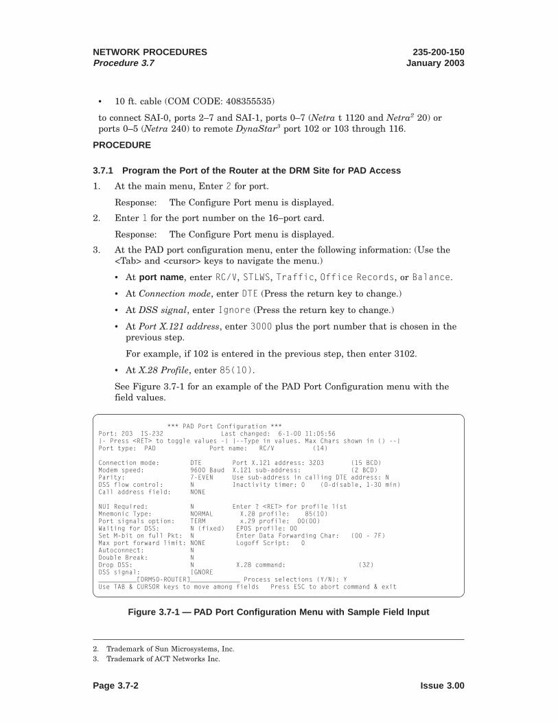
1234567890123456789012345678901212345678901234567890123456123456789012345678901234567890121234567890123456789012345612345678901234567890123456789012123456789012345678901234561234567890123456789012345678901212345678901234567890123456123456789012345678901234567890121234567890123456789012345612345678901234567890123456789012123456789012345678901234561234567890123456789012345678901212345678901234567890123456123456789012345678901234567890121234567890123456789012345612345678901234567890123456789012123456789012345678901234561234567890123456789012345678901212345678901234567890123456123456789012345678901234567890121234567890123456789012345612345678901234567890123456789012123456789012345678901234561234567890123456789012345678901212345678901234567890123456123456789012345678901234567890121234567890123456789012345612345678901234567890123456789012123456789012345678901234561234567890123456789012345678901212345678901234567890123456123456789012345678901234567890121234567890123456789012345612345678901234567890123456789012123456789012345678901234561234567890123456789012345678901212345678901234567890123456123456789012345678901234567890121234567890123456789012345612345678901234567890123456789012123456789012345678901234561234567890123456789012345678901212345678901234567890123456123456789012345678901234567890121234567890123456789012345612345678901234567890123456789012123456789012345678901234561234567890123456789012345678901212345678901234567890123456123456789012345678901234567890121234567890123456789012345612345678901234567890123456789012123456789012345678901234561234567890123456789012345678901212345678901234567890123456
• 10 ft. cable (COM CODE: 408355535)
to connect SAI-0, ports 2–7 and SAI-1, ports 0–7 (Netra t 1120 and Netra2 20) orports 0–5 (Netra 240) to remote DynaStar3 port 102 or 103 through 116.
PROCEDURE
3.7.1 Program the Port of the Router at the DRM Site for PAD Access
1. At the main menu, Enter 2 for port.
Response: The Configure Port menu is displayed.
2. Enter 1 for the port number on the 16–port card.
Response: The Configure Port menu is displayed.
3. At the PAD port configuration menu, enter the following information: (Use the<Tab> and <cursor> keys to navigate the menu.)
• At port name , enter RC/V, STLWS, Traffic, Office Records, or Balance.
• At Connection mode, enter DTE (Press the return key to change.)
• At DSS signal, enter Ignore (Press the return key to change.)
• At Port X.121 address, enter 3000 plus the port number that is chosen in theprevious step.
For example, if 102 is entered in the previous step, then enter 3102.
• At X.28 Profile, enter 85(10).
See Figure 3.7-1 for an example of the PAD Port Configuration menu with thefield values.
2. Trademark of Sun Microsystems, Inc.3. Trademark of ACT Networks Inc.
*** PAD Port Configuration ***Port: 203 IS-232 Last changed: 6-1-00 11:05:56|- Press <RET> to toggle values -| |--Type in values. Max Chars shown in () --|Port type: PAD Port name: RC/V (14)
Connection mode: DTE Port X.121 address: 3203 (15 BCD)Modem speed: 9600 Baud X.121 sub-address: (2 BCD)Parity: 7-EVEN Use sub-address in calling DTE address: NDSS flow control: N Inactivity timer: 0 (0-disable, 1-30 min)Call address field: NONE
NUI Required: N Enter ? <RET> for profile listMnemonic Type: NORMAL X.28 profile: 85(10)Port signals option: TERM x.29 profile: 00(00)Waiting for DSS: N (fixed) EPOS profile: 00Set M-bit on full Pkt: N Enter Data Forwarding Char: (00 - 7F)Max port forward limit: NONE Logoff Script: 0Autoconnect: NDouble Break: NDrop DSS: N X.28 command: (32)DSS signal: IGNORE__________[DRM50-ROUTER]_____________ Process selections (Y/N): YUse TAB & CURSOR keys to move among fields Press ESC to abort command & exit
Figure 3.7-1 — PAD Port Configuration Menu with Sample Field Input
NETWORK PROCEDURESProcedure 3.7
235-200-150January 2003
Page 3.7-2 Issue 3.00

1234567890123456789012345678901212345678901234567890123456123456789012345678901234567890121234567890123456789012345612345678901234567890123456789012123456789012345678901234561234567890123456789012345678901212345678901234567890123456123456789012345678901234567890121234567890123456789012345612345678901234567890123456789012123456789012345678901234561234567890123456789012345678901212345678901234567890123456123456789012345678901234567890121234567890123456789012345612345678901234567890123456789012123456789012345678901234561234567890123456789012345678901212345678901234567890123456123456789012345678901234567890121234567890123456789012345612345678901234567890123456789012123456789012345678901234561234567890123456789012345678901212345678901234567890123456123456789012345678901234567890121234567890123456789012345612345678901234567890123456789012123456789012345678901234561234567890123456789012345678901212345678901234567890123456123456789012345678901234567890121234567890123456789012345612345678901234567890123456789012123456789012345678901234561234567890123456789012345678901212345678901234567890123456
4. Press the left arrow key twice.
Response: The cursor is positioned at Process selections (Y/N).
5. Enter Y.
6. Press the <Esc> key.
Response: The main menu is displayed.
7. At the main menu, enter 3 for configuration.
Response: The Configuration Commands menu is displayed.
8. Enter 6 for asynchronous services.
Response: The Access Server Commands menu is displayed.
9. Enter 5 for Async Services.
Response: The Async Service menu is displayed.
10. At the Async Services menu, enter the following information: (Use the <Tab> and<cursor> keys to navigate the menu.)
• At Service type , enter X.25–Out Stream
• At X.121 address , enter 3000 + <port #>
For example, if 102 was entered, then enter 3102.
• At X.3 Profile , enter 85.
• At Socket Number , enter 3000 + <port #> .
For example, if 102 was entered, then enter 3102.
• At IP address , enter the Ethernet4 IP address of the router at the DRM site.
For example, 10.10.9.254
See Figure 3.7-2 for an example of the Async Services menu with values input.
4. Registered trademark of Xerox Corporation.
*** Async Services ***|- Press <RET> to toggle values -| |-- Type in values. Max chars shown in () --|
Service name: Remote RCV (15)Service type: X25-Out Stream X.121 address: 3203 (15 BCD)
CUG(0-99)X.3 Profile: 85(10) DRM (name or number)
Socket Number: 3203 IP address: 10.10.9.254Telnet command: -N -Q -H FB03 (23)TCP idle timer: OFF (1-255 min)
Call User Data: (16 Hex)
__________[DRMXX-ROUTER]_________________ Process selections (Y/N): YUse <CTRL-D> to delete entryUse TAB & CURSOR keys to move among fields Press ESC to abort command & exit
Figure 3.7-2 — The Async Services Menu with Sample Field Values
235-200-150January 2003
NETWORK PROCEDURESProcedure 3.7
Issue 3.00 Page 3.7-3

Note: Each X.121 address must be unique for each DynaStar box. Therefore, itis recommended that a naming convention be used so that the address for thefirst DRM (node #=1) port 102, the X.121 address will be 3102. (3+1–1) * 1000 +102 = 3102.
For the second DRM, same port, the address will be 4102.
(3+2–1) * 1000 + 102 = 4102.
The limit for X.121 address is 65555.
11. (Enter to access the terminal through Telnet only) At Telnet command , enter -N-Q -H FB03
12. Press the left arrow key twice.
Response: Cursor is displayed at Process selections (Y/N).
13. Enter Y.
14. To save to flash, Enter: <ctrl>w
Response: The settings are saved to memory.
15. Press the <Esc> key until the main menu appears.
Response: The main menu is displayed.
16. Enter <ctrl> ].
Response: Telnet>
17. Enter quit.
Response: Connection Closed.
18. Execute Procedure 3.3.
3.7.2 Program the Serial Port of the OS Router for PAD Access
Note: Use the following procedure only for remote terminal access to DRM SAI PortDevices.
1. At the main menu, enter 3 for configuration.
Response: The Configuration Commands menu is displayed.
2. Enter 6 for Async Services.
Response: The Access Server Commands menu is displayed.
3. Enter 2 for PAD profiles.
Response: The PAD Profiles menu is displayed.
4. At 85(10), enter DRM.
5. At Enter profile number to view/change X.3 parameters , enter 85.
Response: The X.3 Parameter Values menu is displayed.
NETWORK PROCEDURESProcedure 3.7
235-200-150January 2003
Page 3.7-4 Issue 3.00

123456789012345678901234567890121234567890123456789012345612345678901234567890123456789012123456789012345678901234561234567890123456789012345678901212345678901234567890123456123456789012345678901234567890121234567890123456789012345612345678901234567890123456789012123456789012345678901234561234567890123456789012345678901212345678901234567890123456123456789012345678901234567890121234567890123456789012345612345678901234567890123456789012123456789012345678901234561234567890123456789012345678901212345678901234567890123456123456789012345678901234567890121234567890123456789012345612345678901234567890123456789012123456789012345678901234561234567890123456789012345678901212345678901234567890123456123456789012345678901234567890121234567890123456789012345612345678901234567890123456789012123456789012345678901234561234567890123456789012345678901212345678901234567890123456123456789012345678901234567890121234567890123456789012345612345678901234567890123456789012123456789012345678901234561234567890123456789012345678901212345678901234567890123456123456789012345678901234567890121234567890123456789012345612345678901234567890123456789012123456789012345678901234561234567890123456789012345678901212345678901234567890123456123456789012345678901234567890121234567890123456789012345612345678901234567890123456789012123456789012345678901234561234567890123456789012345678901212345678901234567890123456123456789012345678901234567890121234567890123456789012345612345678901234567890123456789012123456789012345678901234561234567890123456789012345678901212345678901234567890123456123456789012345678901234567890121234567890123456789012345612345678901234567890123456789012123456789012345678901234561234567890123456789012345678901212345678901234567890123456
6. Enter 5 for the Idle timer parameter value and 0 for all the remainingparameter.
7. Press the arrow key until the cursor is positioned at Process selections(Y/N)
8. Enter Y.
Response: The Configure Port menu is displayed.
9. Press the <Esc> key until the main menu appears.
Response: The main menu is displayed.
10. At the main menu, enter 3 for configuration.
Response: The Configuration Commands is displayed.
11. Enter 2 for port.
Response: The Configure Port menu is displayed.
12. Enter 1 for 16–port card.
Response: The Configure Port menu is displayed.
13. Enter the port number of the port to be connected.
The last number of the port number is the slot number on the back of theDynaStar. For example, if you want to connect to port 2, choose the port numberthat ends with 2. For example: 102.
Response: The PAD port configuration menu is displayed.
14. At the PAD port configuration menu, enter the following information: (Use the<Tab> and <cursor> keys to navigate the menu.)
• At Port type: , enter PAD
• At Port name , enter Remote RC/V.
*** X.3 Parameter Values ***Profile 85(10)DRM Enter value Permitted values1: PAD recall 0 0-no escape, 1-DLE, 32-126 define char2: PAD echo 0 0-no echo, 1-echo3: Data forwarding chars 0 0, 2, 4, 8, 16, 32, 64, 128, 3-2554: Idle timer 5 0-disabled, 1-255 twentieths of second5: Flow control by PAD 0 0-no use of XON/XOFF, 1-use XON/XOFF6: PAD services signals 0 0-none, 1-no prompt, 5-prompt &*, 8-157: Break handling 0 0, 1, 2, 5, 8, 218: Discard output 0 0-normal delivery, 1-discard9: Padding after CR 0 0-none, 1-255 padding characters10: Line folding 0 0-none, 1-255 graphic characters per line12: Flow control of PAD 0 0-no use of XON/XOFF, 1 use XON/OFF13: LF after CR 0 0, 1, 4, 5, 6, 714: Padding after LF 0 0-none, 1-255 padding characters15: Editing 0 0-none, 1-editing in data transfer16: Character delete 0 0-126 IA5 character, 127-DEL17: Line delete 0 0-23 & 25-127 IA65 character, 24-CAN18: Line display 0 0-17 & 19-127 IA5 character, 18-DC219: Editing signals 0 0-none, 1-printing, 2-display terminal20: Echo mask 0 0, 2, 4, 8, 16, 32, 64, 128, 3-25521: Parity treatment 0 0-none, 3-checking and generation22: Page wait 0 0-disabled, 1-255 LFsPress ESC to abort command & exit Process selections (y/N): Y
Figure 3.7-3 — Example X.3 Parameter Values Screen with Sample Field Values
235-200-150January 2003
NETWORK PROCEDURESProcedure 3.7
Issue 3.00 Page 3.7-5

12345678901234567890123456789012123456789012345678901234561234567890123456789012345678901212345678901234567890123456123456789012345678901234567890121234567890123456789012345612345678901234567890123456789012123456789012345678901234561234567890123456789012345678901212345678901234567890123456123456789012345678901234567890121234567890123456789012345612345678901234567890123456789012123456789012345678901234561234567890123456789012345678901212345678901234567890123456123456789012345678901234567890121234567890123456789012345612345678901234567890123456789012123456789012345678901234561234567890123456789012345678901212345678901234567890123456123456789012345678901234567890121234567890123456789012345612345678901234567890123456789012123456789012345678901234561234567890123456789012345678901212345678901234567890123456123456789012345678901234567890121234567890123456789012345612345678901234567890123456789012123456789012345678901234561234567890123456789012345678901212345678901234567890123456123456789012345678901234567890121234567890123456789012345612345678901234567890123456789012123456789012345678901234561234567890123456789012345678901212345678901234567890123456123456789012345678901234567890121234567890123456789012345612345678901234567890123456789012123456789012345678901234561234567890123456789012345678901212345678901234567890123456123456789012345678901234567890121234567890123456789012345612345678901234567890123456789012123456789012345678901234561234567890123456789012345678901212345678901234567890123456123456789012345678901234567890121234567890123456789012345612345678901234567890123456789012123456789012345678901234561234567890123456789012345678901212345678901234567890123456
• At Connection mode , enter DCE (Use the return key to toggle.)
• At Autoconnect , enter Y-DSS (Use the return key to toggle.)
• At DSS signal , enter IGNORE (Use the return key to toggle.)
• At Port X.121 address , enter 3000 plus the port number that is chosen in theprevious step.
For example, if 102 is entered in the previous step, then enter 3102.
• At X.28 Profile , enter 85(10).
• At X.28 command , enter 3000 plus the port number that is chosen in theprevious step.
For example, if 203 is entered for the previous step, then enter 3203.
Response: See Figure 3.7-4 for an example of PAD Port Configuration Menuwith sample field values.
15. Press the left arrow key twice.
Response: The cursor is positioned at Process selections (Y/N).
16. Enter Y.
Response: The Configure Port menu is displayed.
17. Hold down the Ctrl key and press the w key.
Response: The settings are saved to flash.
18. Press the <Esc> until the main menu appears.
Response: The main menu is displayed.
19. At the main menu, enter 3 for configuration.
Response: The Configuration Commands menu is displayed.
*** PAD Port Configuration ***Port: 102 IS-232 Last changed: 6-1-00 13:39:23|- Press <RET> to toggle values -| |--Type in values. Max Chars shown in () --|Port type: PAD Port name: Remote RC/V (14)
Connection mode: DCE Port X.121 address: 3102 (15 BCD)Modem speed: 9600 Baud X.121 sub-address: (2 BCD)Parity: 7-EVEN Use sub-address in calling DTE address: NDSS flow control: N Inactivity timer: 0 (0-disable, 1-30 min)Call address field: NONE
NUI Required: N Enter ? <RET> for profile listMnemonic Type: NORMAL X.28 profile: 85(10)Port signals option: TERM X.29 profile: 00(00)Waiting for DSS: N (fixed) EPOS profile: 00Set M-bit on full Pkt: N Enter Data Forwarding Char: (00 - 7F)Max port forward limit: NONE Logoff Script: 0Autoconnect: N Retry timer: 10Double Break: N Retry attempts: 1Drop DSS: N X.28 command: 3203 (32)DSS signal: IGNORE__________[OS_ROUTER]_____________ Process selections (Y/N): YUse TAB & CURSOR keys to move among fields Press ESC to abort command & exit
Figure 3.7-4 — PAD Port Configuration for Remote RC/V with Sample Values
NETWORK PROCEDURESProcedure 3.7
235-200-150January 2003
Page 3.7-6 Issue 3.00

20. Enter 6 for Access Services.
Response: The Access Server Commands menu is displayed.
21. Enter 5 for Async service.
Response: The Async Service Names menu is displayed.
22. At the Async Service Names menu, enter the following information: (Use the<Tab> and <cursor> keys to navigate the menu.)
• At service type , enter X.25–In (Use the return key to change.)
• At X.121 address , enter (3+node number— 1) * 1000 + port # Forexample, (3+2–1) * 1000 + 102 is 4102
Note: To identify the node number, identify the order in which the DRMswere added to the network. For example if the DRMs are sequentially added,DRM 1 is node 1, DRM 2 is node 2, and so on.
• At X.3 Profile , enter 85.
• At Socket Number , enter (3+node # — 1) * 1000 + port #.
• At IP address , enter the Ethernet IP address of the router at the DRM site.
For example, 10.10.9.254
23. Press the left arrow key twice.
Response: Cursor is displayed at Process selections (Y/N).
24. Enter Y.
Response: The Async Service Names menu is displayed.
25. To save to flash, enter <ctrl>w
Response: The settings are saved to memory.
26. Press <Esc> until the main menu appears.
Response: The main menu is displayed.
27. STOP. YOU HAVE COMPLETED THIS PROCEDURE.
235-200-150January 2003
NETWORK PROCEDURESProcedure 3.7
Issue 3.00 Page 3.7-7


3.8 Set up the High Speed Interface to send NFM/SCC data to the 5ESS® SwitchHost Site
OVERVIEW
The Network Fault Management (NFM) Operational Support System is located nearthe host 5ESS Switch. The DRM’s total network management (TNM) traffic is routedback to the host over the TCP-IP network. The connection to the OSS router maybeEthernet1 from the Cajun2 P333T from one of the Host routers. The remote routerand the OSS router must support X.25 over TCP-IP (XOT) functionality. At the DRM,the High Speed Interface (port 2) is connected to a synchronous port 203 on theremote router. The remote router and OSS router are programmed with thedestination IP address and port #.
Purpose
Use this procedure to provide access to DRM high speed interface ports by connectingthe ports to the customer operational support services (OSS).
When to Use
The following procedure is used to configure high speed interface to the OSS:
• after the router has been replaced, or
• due to a router that is malfunctioning.
Before You Begin
Required Conditions
The following conditions should exist before the procedure is performed:
• Perform Procedure 8.9, SCC Data Link Growth
• Verify that the router is connected to the network.
• Verify that a terminal (laptop computer or VT100 terminal) is connected to thenetwork.
• Use Procedure 3.1 to get to the main menu of the unit.
• To configure the High Speed Interface, access:
— a control display cut-through window, or
— an MCC terminal.
PROCEDURE
3.8.1 Configure the Router at the DRM Site
3.8.1.1 Remotely Log on to the Networking Router
1. Perform Procedure 3.2, to log on to the router locally.
1. Registered trademark of XEROX Corporation.2. Trademark of AVAYA Communications, Inc.
235-200-150January 2003
NETWORK PROCEDURESProcedure 3.8
Issue 3.00 Page 3.8-1

3.8.1.2 Assign the High Speed Port on the Router at the DRM site
1. Enter 3 for configuration.
Response: The Configuration Commands menu is displayed.
2. Enter 2 for port.
Response: The Configure Port menu is displayed.
3. Enter 2 for Quad-Card.
Response: The Configure Port menu is displayed.
4. Enter 203
Response: The PPP Synchronous Port Configuration menu is displayed.
5. At Port type, enter X.25 line. (Use the return key to change.)
Response: The X.25 Port Configuration menu is displayed.
6. At the x.25 Port Configuration Screen, enter the following information: (Use thearrow keys to navigate the screen)
• At Port name, enter SCC
• At Connection Mode, enter DCE (Use the return key to change.)
• At Line Speed, enter 9.6 Kbps (Use the return key to change.)
• At X.25 mode, enter DCE (Use the return key to change.)
• At Max Packet size, enter 256 (Use the return key to change.)
• At IPX Routing, enter N (Use the return key to change.)
• At Ethernet Routing, enter N (Use the return key to change.)
• At Permanent/Number of VCs, enter 7
7. Press the left arrow twice.
Response: The cursor is positioned at Process Selections (Y/N).
8. Enter Y
Response: The Configure Port menu is displayed.
9. To save to flash, Enter : <ctrl>w
10. Press the esc key until the main menu is displayed.
Response: The main menu is displayed.
3.8.1.3 Assign XOT and define the remote IP Address, port and LCN
1. Enter 3 for configuration.
Response: The Configuration Commands menu is displayed.
2. Enter 10 for X.25.
Response: The X.25 Parameters menu is displayed.
3. Enter 5 for XOT switching table.
Response: The XOT PVC SCV Switching Table is displayed.
NETWORK PROCEDURESProcedure 3.8
235-200-150January 2003
Page 3.8-2 Issue 3.00

4. For each of the 7 LCNs, enter the following information: (Use the arrow keys tonavigate the screen)
• At Service, enter PVC/XOT (Use the return key to change.)
• At LOCAL PORT #, enter 203
• At LOCAL LCN #, enter 1, 2, 3, 4, 5, 6, or 7
• At REMOTE PORT #, enter the port number for the OS Router that handlesSCC traffic.
• At REMOTE LCN #, enter 1, 2, 3, 4, 5, 6, or 7
• At REMOTE IP Address, enter the IP Address for the OS Router that handlesSCC traffic
5. Press the left arrow key twice.
Response: The cursor is positioned at Process Selections (Y/N).
6. Enter Y.
7. Hold down the Ctrl key and press the W key.
8. Hold down the Ctrl key and press the ] key.
9. Enter quit
3.8.2 At the Host Site, Connect the OSS Router to the Router at the DRM Site
3.8.2.1 Connect the SCC Router at the DRM Site to the OSS Router
Note: If the remote OS router is not to be used to set up a permanent connection forIP routing from a router at the DRM site, use local procedures instead of the followingprocedure to set up the permanent connection for IP routing between the remoterouter and the OS router.
1. Enter 3 for configuration.
Response: The Configuration Commands menu is displayed.
2. Enter 2 for port.
Response: The Configure Port menu is displayed.
3. Enter the port number to which you wish to connect.
Note: The last number of the port number is the slot number on the back of theDynaStar. If you want to connect to port 2, choose the port number that endswith 2. For example: 102.
Response: The PPP Synchronous Port Configuration menu is displayed.
4. At Port type, enter X.25 line. (Use the return key to change.)
Response: The X.25 Port Configuration menu is displayed.
5. At the X.25 Port Configuration menu, enter the following information: (Use thearrow keys to navigate the screen)
• At Port name, enter NFM.
• At Connection Mode, enter DTE (Use the return key to change.)
235-200-150January 2003
NETWORK PROCEDURESProcedure 3.8
Issue 3.00 Page 3.8-3

• At Line Speed, enter 2.4 Kbps (Use the return key to change.)
• At X.25 mode, enter DTE (Use the return key to change.)
• At Max Packet size, enter 256 (Use the return key to change.)
• At IPX Routing, enter N.
• At Ethernet Routing, enter N (Use the return key to change.)
• At Permanent/Number of VCs, enter 7.
6. Press the left arrow twice.
Response: The cursor is positioned at Process Selections (Y/N).
7. Enter Y
Response: The Configure Port menu is displayed.
8. Hold down the Ctrl key and press the W key.
9. Enter <Esc> to return to the main menu.
Response: The main menu is displayed.
3.8.2.2 Assign XOT and Define the Remote IP Address, Port and LCN
1. Enter 3 for configuration.
Response: The Configuration Commands menu is displayed.
2. Enter 10 for X.25.
Response: The X.25 Parameters menu is displayed.
3. Enter 5 for XOT switching table.
Response: The XOT PVC SCV Switching Table is displayed.
4. For each of the 7 LCNs, enter the following information:
• At Service, enter PVC/XOT (Use the return key to change.)
• At LOCAL PORT #, enter the port number for the OS Router that handlesSCC traffic.
• At LOCAL LCN #, enter 1, 2, 3, 4, 5, 6, or 7
• At REMOTE PORT #, enter 203
• At REMOTE LCN #, enter 1, 2, 3, 4, 5, 6, or 7
• At REMOTE IP Address, enter the IP Address for the OS Router that handlesSCC traffic
5. Press the left arrow key twice.
Response: The cursor is positioned at Process Selections (Y/N).
6. Enter Y.
7. Hold down the Ctrl key and press the W key.
8. Hold down the Ctrl key and press the ] key.
9. Enter quit
NETWORK PROCEDURESProcedure 3.8
235-200-150January 2003
Page 3.8-4 Issue 3.00
10. Perform Procedure 3.3, Back up the DynaStar 5003
3. Trademark of DYMEC, Inc.
235-200-150January 2003
NETWORK PROCEDURESProcedure 3.8
Issue 3.00 Page 3.8-5


3.9 Set up the High Speed Interface to Send EADAS Data to the Host Site
Purpose
The following procedure is used to set up the High Speed Interface to send EADASdata to the Host Site.
Reason to Perform
The following procedure should be used to provide access to DRM High SpeedInterface ports by connecting the High Speed Interface ports to the customeroperational support services (OSS).
Before You Begin
The following factors must be considered before you begin the procedure:
Required Conditions
The following conditions should exist before the procedure is performed:
• Verify that the router is connected to the network.
• Verify that a terminal (laptop computer or VT100 terminal) is connected to thenetwork.
PROCEDURE
3.9.1 Access the High Speed Interface
1. Access the High Speed Interface from:
• a control display cut-through window, or
• an MCC.
3.9.2 Install the EADAS Router at the DRM Site
1. Perform Procedure 8.11 to grow TDMS/EADAS Data Links and connect the HighSpeed Interface port to the router port cable.
3.9.3 Configure the Router at the DRM Site
3.9.3.1 Assign the High Speed Interface Port on the Router at the DRM site
1. Perform Procedure 3.2 to remotely log on to the networking router.
2. Enter 3 for configuration.
Response: The Configuration Commands menu is displayed.
3. Enter 2 for port.
Response: The Configure Port menu is displayed.
4. Enter 2 for Quad-Card.
Response: The Configure Port menu is displayed.
5. Enter 204
Response: The PPP Synchronous Port Configuration menu is displayed.
235-200-150January 2003
NETWORK PROCEDURESProcedure 3.9
Issue 3.00 Page 3.9-1

6. At Port type,, enter X.25 line. (Use the return key to change.)
Response: The X.25 Port Configuration menu is displayed.
7. At the x.25 Port Configuration Screen, enter the following information: (Use thearrow keys to navigate the screen)
• At Port name, enter EADAS
• At Connection Mode, enter DCE (Use the return key to change.)
• At Line Speed, enter 64 Kbps (Use the return key to change.)
• At X.25 mode, enter DCE (Use the return key to change.)
• At Max Packet size, enter 256 (Use the return key to change.)
• At IPX Routing, enter N (Use the return key to change.)
• At Ethernet Routing, enter N (Use the return key to change.)
• At Permanent/Number of VCs, enter 3
8. Press the left arrow twice.
Response: The cursor is positioned at Process Selections (Y/N).
9. Enter Y
Response: The Configure Port menu is displayed.
10. To save to flash, Enter <ctrl>w.
11. Press the <Esc> to return to the main menu.
Response: The main menu is displayed.
3.9.3.2 Assign XOT and define the remote IP Address, port and LCN
1. Enter 3 for configuration.
Response: The Configuration Commands menu is displayed.
2. Enter 10 for X.25.
Response: The X.25 Parameters menu is displayed.
3. Enter 5 for XOT switching table.
Response: The XOT PVC SCV Switching Table is displayed.
4. For each of the 7 LCNs, enter the following information: (Use the arrow keys tonavigate the screen)
• At Service, enter PVC/XOT (Use the return key to change.)
• At LOCAL PORT #, enter 204
• At LOCAL LCN #, enter 1, 2, 3, 4, 5, 6, or 7
• At REMOTE PORT #, enter the port number for the OS Router that handlesEADAS traffic.
• At REMOTE LCN #, enter 1, 2, 3, 4, 5, 6, or 7
• At REMOTE IP Address, enter the IP Address for the OS Router that handlesEADAS traffic.
NETWORK PROCEDURESProcedure 3.9
235-200-150January 2003
Page 3.9-2 Issue 3.00

5. Press the left arrow key twice.
Response: The cursor is positioned at Process Selections (Y/N).
6. Enter Y.
7. Hold down the Ctrl key and press the W key.
8. Hold down the Ctrl key and press the ] key.
9. Enter quit
10. Perform Procedure 3.3, Back up the DynaStar 5001
3.9.4 At the Host Site, Connect the OSS Router to the Router at the DRM Site
3.9.4.1 Connect the EADAS to the OSS Router
Note: If the remote OS router is not to be used to set up a permanent connection forIP routing from a router at the DRM site, use local procedures instead of the followingprocedure to set up the permanent connection for IP routing between the remoterouter and the OS router
1. Enter 3 for configuration.
Response: The Configuration Commands menu is displayed.
2. Enter 2 for port.
Response: The Configure Port menu is displayed.
3. Enter the port number to which you wish to connect.
Note: The last number of the port number is the slot number on the back of theDynaStar.
If you want to connect to port 2, choose the port number that ends with 2. Forexample: 102.
Response: The PPP Synchronous Port Configuration menu is displayed.
4. At Port type, enter X.25 line. (Use the return key to change.)
Response: The X.25 Port Configuration menu is displayed.
5. At the X.25 Port Configuration menu, enter the following information: (Use thearrow keys to navigate the screen)
• At Port name, enter EADAS.
• At Connection Mode, enter DTE (Use the return key to change.)
• At Line Speed, enter 64 Kbps (Use the return key to change.)
• At X.25 mode, enter DTE (Use the return key to change.)
• At Max Packet size, enter 256 (Use the return key to change.)
• At IPX Routing, enter N.
• At Ethernet Routing, enter N (Use the return key to change.)
1. Trademark of DYMEC, Inc.
235-200-150January 2003
NETWORK PROCEDURESProcedure 3.9
Issue 3.00 Page 3.9-3

• At Permanent/Number of VCs, enter 3.
6. Press the left arrow twice.
Response: The cursor is positioned at Process Selections (Y/N).
7. Enter Y
Response: The Configure Port menu is displayed.
8. Enter <Ctrl>w.
9. Press the <Esc> key until the main menu is displayed.
Response: The main menu is displayed.
3.9.4.2 Assign XOT and define the remote IP Address, port and LCN
1. Enter 3 for configuration.
Response: The Configuration Commands menu is displayed.
2. Enter 10 for X.25.
Response: The X.25 Parameters menu is displayed.
3. Enter 5 for XOT switching table.
Response: The XOT PVC SCV Switching Table is displayed.
4. For each of the 7 LCNs, enter the following information: (Use the arrow keys tonavigate the screen)
• At Service, enter PVC/XOT (Use the return key to change.)
• At LOCAL PORT #, enter the port number for the OS Router that handlesEADAS traffic.
• At LOCAL LCN #, enter 1, 2, 3, 4, 5, 6, or 7
• At REMOTE PORT #, enter 204
• At REMOTE LCN #, enter 1, 2, 3, 4, 5, 6, or 7
• At REMOTE IP Address, enter the IP Address for the OS Router that handlesEADAS traffic
5. Press the left arrow key twice.
Response: The cursor is positioned at Process Selections (Y/N).
6. Enter Y.
7. Hold down the Ctrl key and press the W key.
8. Hold down the Ctrl key and press the ] key.
9. Enter quit
10. Perform Procedure 8.11.7 to verify operations of TDMS/EADAS Data Link
11. Perform Procedure 8.11.8 to back up office dependent data.
NETWORK PROCEDURESProcedure 3.9
235-200-150January 2003
Page 3.9-4 Issue 3.00

3.10 Install the BRI to PRI to Back up the T1
OVERVIEW
The T1 facility can have a back up connection established when the T1 connection isunavailable. In order to back up the T1, a BRI is used at the remote site. OneB-channel is used as a 64K backup channel when the T1 connectivity is lost. It doesnot provide the same throughput as a 1.544K T1 but allows for maintenance activitiesto take place. The BRI at remote site is a purchased by the customer. It must be aNational ISDN BRI with CSD 64KB Clear capabilities on B-channel 1, a 10-digit CSDDN, and a SPID.
Purpose
Use this procedure to set up the BRI to PRI backup for the T1.
When to Use
The following procedure is used to provide a backup mechanism for the network whenthe T1 is not accessible.
To create a T1 backup for the network, each of the up to 15 BRIs and one PRI need tobe configured. In this configuration, the PRI is located at the 5ESS® switch site andthe BRI is located at each DRM site.
Before You Begin
The following factors must be considered before you begin the procedure:
Required Conditions
The following conditions should exist before the procedure is performed:
• Verify that the router is connected to the network.
• Verify that a terminal (laptop computer or VT100 terminal) is connected to thenetwork.
PROCEDURE
3.10.1 Install the PRI at the Host Site
1. t the Host Site, Connect Router 00 to Port 301 and the MDF.
3.10.1.1 Assign Trunk type as T1 PRI
1. Enter 3 for configuration.
Response: The Configuration Commands menu is displayed.
2. Enter 2 for port.
Response: The Configure Port menu is displayed.
3. Enter 300 for PRI.
Response: The T1 Trunk Parameters menu is displayed.
4. Enter 1.
5. Enter the following information: (Use the arrow keys to navigate the screen.)
• At Trunk Type, enter T1 PRI. (Use return key to change.)
235-200-150January 2003
NETWORK PROCEDURESProcedure 3.10
Issue 3.00 Page 3.10-1

• At Trunk Name, enter PRI
• At FrameType, enter D4. (Use return key to change.)
6. Press the left arrow.
Response: The cursor is positioned at process selections (Y/N).
7. Enter y.
8. Press the esc key until the main menu is displayed.
Response: The main menu is displayed.
3.10.1.2 Assign Incoming Telephone Number for the PRI
1. Enter 3 for configuration.
Response: The Configuration Commands menu is displayed.
2. Enter 2 for port.
Response: The Configure Port menu is displayed.
3. Enter 300 for PRI.
Response: The T1 Trunk Parameters menu is displayed.
4. Enter 2 for Configure Incoming Telephone Number and SPIDs.
5. Enter the PRI access telephone number.
6. Press the left arrow.
Response: The cursor is positioned at process selections (Y/N).
7. Enter y.
8. Press the esc key until the main menu is displayed.
Response: The main menu is displayed.
3.10.1.3 Assign Router 00, PRI IP Addresses/Masks/Protocols
1. Enter 3 for configuration.
Response: The Configuration Commands menu is displayed.
2. Enter 3 for router.
Response: The Router Commands menu is displayed.
3. Enter 5 for IP Port Information.
Response: The IP Port Information menu is displayed.
4. At the IP Port Information menu, enter the following information: (Use the arrowkeys to navigate the screen.)
• At IP Address, enter the PRI IP Address.
• At IP mask, enter the PRI port IP mask
• At Protocol, enter RIP II. (Use the return key to change.)
NETWORK PROCEDURESProcedure 3.10
235-200-150January 2003
Page 3.10-2 Issue 3.00

5. Press the left arrow.
Response: The cursor is positioned at process selections (Y/N).
6. Enter Y.
7. Hold down the Ctrl key and press the w key.
Response: The settings are saved to flash.
8. Press the esc key until the main menu is displayed.
Response: The main menu is displayed.
3.10.2 Save the Configuration Files Remotely
3.10.2.1 Host Networking Router Configuration File Back Up Procedure
1. Perform Procedure 3.4, Backup The DynaStar 5001 (Base/Growth) Router at theHost Site, to remotely save the configuration files.
3.10.2.2 Connect the Router to BRI Port 301 and the MDF
1. At the DRM site, connect the router to BRI port 301 and the MDF.
3.10.3 Program the BRI at the remote router
3.10.3.1 PPP Dial Entry to access the PRI
1. Enter 3 for configuration.
Response: The Configuration Commands menu is displayed.
2. Enter 1 for PPP Dial Directions.
Response: The PPP Dial Directions menu is displayed.
3. Press Return.
Response: The PPP Dial Directory Entry menu is displayed.
4. Enter the following information: (Use the arrow keys to navigate the screen.)
• At the Location Name, enter BRI to Host.
• At ISDN Interface, enter BRI
• At PhoneNumber, enter the PRI Access telephone number.
• At IP Routing, enter y (Use the return key to change.)
• At the Remote IP address, enter the PRI port IP Address of Router 00 at theHost Site
• At the Local IP address, enter the BRI port IP Address of the router at theDRM site
For example, 10.10.8.26
1. Trademark of DYMEC, Inc.
235-200-150January 2003
NETWORK PROCEDURESProcedure 3.10
Issue 3.00 Page 3.10-3

• At Local Mask address, enter the BRI Port SubNet of the router at the DRMsite
For example, 255.255.255.252
5. Press the left arrow twice.
Response: The cursor is positioned at process selections (Y/N).
6. Enter y.
7. Press the esc key until the main menu is displayed.
Response: The main menu is displayed.
3.10.3.2 Configure the D-channel
1. Enter 3 for configuration.
Response: The Configuration Commands menu is displayed.
2. Enter 2 for port.
Response: The Configure Port menu is displayed.
3. Enter 300 for BRI.
Response: The ISDN Port Configuration menu is displayed.
4. Enter 1 to configure PRI/BRI D Channels.
Response: The ISDN D Channel menu is displayed.
5. At Port Name, enter BRI.
6. Press the left arrow.
Response: The cursor is positioned at process selections (Y/N).
7. Enter y.
8. Press the esc key until the main menu is displayed.
Response: The main menu is displayed.
3.10.3.3 Configure ISDN Incoming Telephone Numbers
1. Enter 3 for configuration.
Response: The Configuration Commands menu is displayed.
2. Enter 2 for port.
Response: The Configure Port menu is displayed.
3. Enter 300 for BRI.
Response: The ISDN Port Configuration menu is displayed.
4. Enter 2 to configure incoming telephone numbers.
Response: The ISDN Incoming Telephone Number and SPID menu isdisplayed.
NETWORK PROCEDURESProcedure 3.10
235-200-150January 2003
Page 3.10-4 Issue 3.00

5. Enter the following information in slot 1: (Use the arrow keys to navigate thescreen.)
• At Telephone #, enter circuit-switched data telephone number of the BRI
• At SPID, enter the service Profile ID for the BRI
6. Press the left arrow.
Response: The cursor is positioned at process selections (Y/N).
7. Enter y.
8. Press the esc key until the main menu is displayed.
Response: The main menu is displayed.
9. Configure ISDN B Channel Port Configuration.
At the main menu, enter 3.
10. Enter 3 for configuration.
Response: The Configuration Commands menu is displayed.
11. Enter 2 for port.
Response: The Configure Port menu is displayed.
12. Enter 300 for BRI.
Response: The ISDN Port Configuration menu is displayed.
13. Enter 3 for B Channel Ports.
Response: The IP Port Information menu is displayed.
14. Enter the following information for Port 301 and Port 302: (Use the arrow keysto navigate the screen.)
• At Use, enter IN/OUT. (Use the return key to change.)
• At Inbound Tel #, enter the 10 digit telephone # for the BRI
• At Protocol, enter PPP.
• At Class, enter NONE.
• At ML, enter N.
15. Press the left arrow.
Response: The cursor is positioned at process selections (Y/N).
16. Enter y.
17. Press the esc key until the main menu is displayed.
Response: The main menu is displayed.
3.10.3.4 Configure PRI Board Addresses/Masks/Protocols
1. Enter 3 for configuration.
Response: The Configuration Commands menu is displayed.
235-200-150January 2003
NETWORK PROCEDURESProcedure 3.10
Issue 3.00 Page 3.10-5

2. Enter 3 for router.
Response: The Router Commands menu is displayed.
3. Enter 5 for IP Port Information.
Response: The IP Port Information menu is displayed.
4. At the IP Port Information menu, enter the following information for the BRIport: (Use the arrow keys to navigate the screen.)
• At IP Address, enter the BRI IP Address.
For example, 10.10.8.26
• At IP mask, enter the BRI port IP mask
• At Protocol, enter RIP II. (Use the return key to change.)
5. Press the left arrow.
Response: The cursor is positioned at process selections (Y/N).
6. Enter y.
3.10.3.5 Add the BRI as a T1 back up (T1 connection to host) to the TDM Channel(port 8)
1. Enter 3 for configuration.
Response: The Configuration Commands menu is displayed.
2. Enter 2 for port.
Response: The Configure Port menu is displayed.
3. Enter 8 for T1 to Host.
Response: The Frame Relay Port Configuration menu is displayed.
4. Enter the following information: (Use the arrow keys to navigate the screen.)
• At Circuit Backup, enter Y. (Use return key to change.)
• At Backup when line Down, enter 150.
• At Restore when line Up, enter 30.
• At Backup Location Name, enter BRI to Host.
5. Press the left arrow.
Response: The cursor is positioned at process selections (Y/N).
6. Enter y.
7. Press the esc key until the main menu is displayed.
Response: The main menu is displayed.
8. Hold down the Ctrl key and press the w key.
Response: The settings are saved to flash.
NETWORK PROCEDURESProcedure 3.10
235-200-150January 2003
Page 3.10-6 Issue 3.00

3.10.4 Verify that BRI to PRI backup connection is established
1. Login to the Remote-Networking Router.
1. Go to the call status page and watch the call status.
2. At the Main Menu, enter 1.
3. Enter 2.
2. Remove the T1 connection from port on the Remote-Networking Router. After 150seconds the BRI to PRI backup connection is established. The call status pageshould indicate that it has been done.
3. Restore the T1 connection, the call status should be disconnected.
235-200-150January 2003
NETWORK PROCEDURESProcedure 3.10
Issue 3.00 Page 3.10-7


3.11 DRM Network Element Software Download Procedure
Purpose
The DRM Network Element Software Download Procedure is used to download a newversion of software to a Cajun P333T switch or DynaStar 500 router configured in aDRM network.
When To Use
This procedure is performed when Lucent Technologies, Inc. has issued anInformational Software Update advertising an update to the Cajun switch orDynaStar router software. When an update is advertised, a Cajun switch or DynaStarrouter software download package will be available on the Lucent Electronic Delivery(LED) system.
A PDF file describing the Lucent Electronic Delivery directory structure at a highgeneric release level is published to the Customer Support/Download Section ofwww.lucent.com. This file entitled Dir_Structure.pdf provides navigational direction toupload/download software to/from the Lucent Electronic Delivery network.
The naming conventions for DRM software delivery products on Lucent ElectronicDelivery are in the following format: DRMyy-xxxx.zip.
Where: yy = a two-digit yearxxxx = a four-digit sequence numberzip = a zip(compressed) file
When a DynaStar router software package is available, the software will need to bedownloaded to all the routers in the DRM network. The DynaStar Router SoftwareDownload Procedure contained within the software package must be executed in itsentirety for each router in the network.
Before You Begin
An understanding of the DRM network using the Lucent Technologies NetworkComponent Solution (LNCS) is required. See, Section 2.7, The DRM Network for moreinformation.
Caution: Executing the Cajun switch or DynaStar router software downloadprocedure will result in loss of communication between the ASM (host) andone or more DRMs (remote) as follows:
• After software is downloaded to the Cajun switch, a reset is performed to restartthe switch to run the new software. During the reset, communication is lostbetween the ASM and all DRMs for approximately 1 minute.
• After software is downloaded to a host DynaStar router, a reset is performed torestart the router to run the new software. During the reset, communication islost between the ASM and up to 5 DRMs accessed by the host router forapproximately 5 minutes. The following table shows the host router to DRMmapping:
235-200-150August 2004
NETWORK PROCEDURESProcedure 3.11
Issue 3.00K Page 3.11-1

Table 3.11-1 — Host Router To DRM Mapping Table
Host DynaStar Router 00 (host_a) DRM1 – DRM5Host DynaStar Router 01 (host_b) DRM6 – DRM10Host DynaStar Router 02 (host_c) DRM11 – DRM 15
• After software is downloaded to the remote DynaStar router, a reset is performedto restart the router to run the new software. During the reset, communication islost between the ASM and the single DRM accessed by the remote router forapproximately 5 minutes.
Once communication is lost between the ASM and DRM(s), ASM services will begin tofail resulting in multiple error messages on the ROP. The ASM GUI and DRM 124display page will also show the status for the ASM services as degraded. It may takeup to 30 minutes for the ASM to restore the services after the network connection hasbeen restored.
Executing this procedure to download software and re-initialize a Cajun switch willtake approximately 10 minutes.
Executing this procedure to download software and re-initialize a DynaStar router willtake approximately 10 minutes, not including ASM or DRM backups.
Required Tools
Access to the ASM with root permission is required.
Required Conditions
Log onto the ASM with root permission. If an HA-ASM configuration is being used,perform this procedure from the “lead” ASM. For more information, see Section“Accessing the ASM,” in 235-200-145, OneLink Manager Administrative ServicesModule User’s Guide.
Required Information
Before beginning this procedure, obtain the passwords and the IP addresses for theASM and Cajun switch or DynaStar routers that will be downloaded with newsoftware. This information should be stored in the office records. The following tableprovides the Lucent defined default IP addresses, a column to record the customerdefined IP addresses if used, and a column to record the network element softwareversion number.
NETWORK PROCEDURESProcedure 3.11
235-200-150August 2004
Page 3.11-2 Issue 3.00K

Table 3.11-2 — IP Addresses and Software Versions Table
DRM Network Element Lucent IP Address Customer IP Address Version NumberSimple ASM or HA ASM 1 10.10.1.1HA ASM 2 10.10.1.2Host Cajun Switch 10.10.1.245Host DynaStar Router 00 10.10.1.254Remote DynaStar Router – DRM 1 10.10.9.254Remote DynaStar Router – DRM 2 10.10.10.254Remote DynaStar Router – DRM 3 10.10.11.254Remote DynaStar Router – DRM 4 10.10.12.254Remote DynaStar Router – DRM 5 10.10.13.254Host DynaStar Router 01 10.10.1.253Remote DynaStar Router – DRM 6 10.10.17.254Remote DynaStar Router – DRM 7 10.10.18.254Remote DynaStar Router – DRM 8 10.10.19.254Remote DynaStar Router – DRM 9 10.10.20.254Remote DynaStar Router – DRM 10 10.10.21.254Host DynaStar Router 02 10.10.1.252Remote DynaStar Router – DRM 11 10.10.25.254Remote DynaStar Router – DRM 12 10.10.26.254Remote DynaStar Router – DRM 13 10.10.27.254Remote DynaStar Router – DRM 14 10.10.28.254Remote DynaStar Router – DRM 15 10.10.29.254
PROCEDURE
3.11.1 Transfer A DRM Network Element Software Package From The LED SystemTo The ASM.
Caution: If errors occur during this procedure, seek next level of technicalsupport.
1. At the ASM UNIX1 shell prompt, type and enter:
cd /tftpboot
Response:
ASM UNIX shell prompt will display.
2. Create working directory for the software download package, type and enter:
/bin/mkdir drm
Response:
ASM UNIX shell prompt will display.
3. Type and enter:
/bin/chmod 777 drm
1. Registered trademark in the United States and other countries licensed exclusively through X/OpenCompany Limited
235-200-150August 2004
NETWORK PROCEDURESProcedure 3.11
Issue 3.00K Page 3.11-3

Response:
ASM UNIX shell prompt will display.
4. Type and enter:
cd drm
Response:
ASM UNIX shell prompt will display.
5. Connect to the Lucent Electronic Delivery system, type and enter:
/bin/ftp 206.242.19.65
Response:
Messages similar to:Connected to 206.242.19.65220 scansdmzFTP server (operating system version info) ready.
Followed by a login prompt.
6. Enter the appropriate Lucent Electronic Delivery login/password to connect.
Response:
A successful login returns a message similar to:230 User <login ID> logged in. Access restrictions apply.ftp>
7. Type and enter:
binary
Response:
A message similar to:200 Type set to I.ftp>
8. Change directory to the location of the software download package on LucentElectronic Delivery, type and enter:
cd /5ESS/5Eg.v/VCDXg.v/zip
Where: g.v = 5E generic and version numbers
Response:
A message similar to:250 CWD command successful.ftp>
9. Transfer the software download package to the ASM, type and enter:
get DRMyy-xxxx.zip
Where: DRM = update for a DRM network elementyy = the last 2 digits of the yearxxxx = sequence number
Response:
NETWORK PROCEDURESProcedure 3.11
235-200-150August 2004
Page 3.11-4 Issue 3.00K
A message similar to:226 Binary Transfer complete.
Followed by the number of "bytes" and "time" it took to get the file from LucentElectronic Delivery.ftp>
10. Type and enter:
quit
Response:
A message similar to:221 Goodbye.
Followed by the ASM UNIX shell prompt.
3.11.2 Execute the Cajun Switch or DynaStar Router Software Download Procedure
1. Extract the DRM Network Element software image file(s) and downloadprocedure from the zip file. Type and enter:
/app/asm/sbin/unzip -j DRMyy-xxxx.zip
Where: DRM = update for a DRM network elementyy = the last 2 digits of the yearxxxx = sequence number
Response:
A message similar to:Archive: DRMyy-xxxx.zip
inflating: HDR...
Followed by the ASM UNIX shell prompt.
2. Display and execute the Cajun switch or DynaStar router software downloadprocedure. Type and enter:
/bin/pg /tftpboot/drm/MSGS.proc{version number}
Where: version number = Cajun switch or DynaStar router software versionidentified by the Informational Software Update advertising anupdate.
Response:
The first page of the software download procedure is displayed. Select the[return] key to display the next page of the procedure.
Execute all steps documented in the Cajun switch or DynaStar router softwaredownload procedure.
If executing the DynaStar router software download procedure, repeat this stepfor each DynaStar router configured in the DRM network before continuing tothe next step.
235-200-150August 2004
NETWORK PROCEDURESProcedure 3.11
Issue 3.00K Page 3.11-5

If executing the Cajun switch software download procedure, continue to the nextstep.
3. Type and enter:
cd /tftpboot
Response:
ASM UNIX shell prompt will display.
4. Remove directory structure and files created by this procedure. Type and enter:
/bin/rm –rf drm
Response:
ASM UNIX shell prompt will display.
5. Exit from the ASM UNIX shell. Type and enter:
exit
Response:
ASM login prompt will display.
6. STOP. YOU HAVE COMPLETED THIS PROCEDURE.
NETWORK PROCEDURESProcedure 3.11
235-200-150August 2004
Page 3.11-6 Issue 3.00K
3.12 Cajun Switch Software Version Procedure
Purpose
The Cajun Switch Software Version Procedure is used to obtain the version numberfor the software running on a Cajun switch configured in a DRM network.
Before You Begin
An understanding of the DRM network using the Lucent Technologies NetworkComponent Solution (LNCS) is required. See, Section 2.7, The DRM Network for moreinformation.
Required Tools
Access to the ASM with root permission is required.
Required Conditions
Log onto the ASM with root permission. If an HA-ASM configuration is being used,perform this procedure from the “lead” or “standby” ASM. For more information, seeSection “Accessing the ASM,” in 235-200-145, OneLink Manager AdministrativeServices Module User’s Guide.
Required Information
Before beginning this procedure, obtain the IP address for the Cajun switch. Thisinformation should be stored in the office records. The following table provides theLucent defined default IP address, a column to record the customer defined IP addressif used, and a column to record the Cajun switch software version number.
235-200-150April 2004
NETWORK PROCEDURESProcedure 3.12
Issue 3.00G Page 3.12-1

Table 3.12-1 — Host Cajun IP Addresse and Software Version Table
DRM Network Element Lucent IP Address Customer IP Address Version NumberHost Cajun Switch 10.10.1.245
PROCEDURE
1. Establish a telnet connection to the Cajun switch, type and enter:
telnet X
Where: X = the Cajun IP Address
Response:
The software version number will be displayed with the Cajun switch welcomemessage followed by a login prompt.
2. Exit from the Cajun switch login prompt, type and enter:
[Ctrl] + ]
(the control key followed by the left square bracket pressed at the same time)
Response:
Telnet prompt will display.
3. Exit from the telnet session, type and enter:
quit
Response:
ASM UNIX1 shell prompt will display.
4. STOP. YOU HAVE COMPLETED THIS PROCEDURE.
1. Registered trademark in the United States and other countries licensed exclusively through X/OpenCompany Limited
NETWORK PROCEDURESProcedure 3.12
235-200-150April 2004
Page 3.12-2 Issue 3.00G

3.13 DynaStar Router Software Version Procedure
Purpose
The DynaStar Router Software Version Procedure is used to obtain the versionnumber for the software running on a DynaStar router configured in a DRM network.
Before You Begin
An understanding of the DRM network using the Lucent Technologies NetworkComponent Solution (LNCS) is required. See, Section 2.7, The DRM Network for moreinformation.
Required Tools
Access to the ASM with root permission is required.
Required Conditions
Log onto the ASM with root permission. If an HA-ASM configuration is being used,perform this procedure from the “lead” or “standby” ASM. For more information, seeSection “Accessing the ASM,” in 235-200-145, OneLink Manager AdministrativeServices Module User’s Guide.
Required Information
Before beginning this procedure, obtain the IP address for the DynaStar routers. Thisinformation should be stored in the office records. The following table provides theLucent defined default IP addresses, a column to record the customer defined IPaddresses if used, and a column to record the DynaStar routers software versionnumbers.
235-200-150April 2004
NETWORK PROCEDURESProcedure 3.13
Issue 3.00G Page 3.13-1

Table 3.13-1 — DynaStar Router IP Addresses and Software Versions Table
DRM Network Element Lucent IP Address Customer IP Address Version NumberHost DynaStar Router 00 10.10.1.254Remote DynaStar Router – DRM 1 10.10.9.254Remote DynaStar Router – DRM 2 10.10.10.254Remote DynaStar Router – DRM 3 10.10.11.254Remote DynaStar Router – DRM 4 10.10.12.254Remote DynaStar Router – DRM 5 10.10.13.254Host DynaStar Router 01 10.10.1.253Remote DynaStar Router – DRM 6 10.10.17.254Remote DynaStar Router – DRM 7 10.10.18.254Remote DynaStar Router – DRM 8 10.10.19.254Remote DynaStar Router – DRM 9 10.10.20.254Remote DynaStar Router – DRM 10 10.10.21.254Host DynaStar Router 02 10.10.1.252Remote DynaStar Router – DRM 11 10.10.25.254Remote DynaStar Router – DRM 12 10.10.26.254Remote DynaStar Router – DRM 13 10.10.27.254Remote DynaStar Router – DRM 14 10.10.28.254Remote DynaStar Router – DRM 15 10.10.29.254
PROCEDURE
1. Establish a telnet connection to the DynaStar router, type and enter:
telnet X
Where: X = the DynaStar IP Address
Response:Enter service selection
2. Select the DynaStar router CONSOLE service, type and enter:
1
Response:
The software version number will be displayed on the DynaStar routersupervisor page followed by a login password prompt.
3. Exit from the DynaStar router login password prompt, type the Escape key:
[Esc]
Response:
ASM UNIX1 shell prompt will display.
4. STOP. YOU HAVE COMPLETED THIS PROCEDURE.
1. Registered trademark in the United States and other countries licensed exclusively through X/OpenCompany Limited
NETWORK PROCEDURESProcedure 3.13
235-200-150April 2004
Page 3.13-2 Issue 3.00G

3.14 Replace the Cajun P333T Ethernet Switch
Purpose
This procedure is used to replace a defective Cajun P333T Ethernet Switch in theLucent Network Component Solution (LNCS) configuration with a replacement CajunP333T Ethernet Switch.
When to Use
This procedure is used to replace only a defective Cajun P333T Ethernet Switch. Thereplacement of any other Cajun switch model, an ethernet switch of anothermanufacturer, or a Cajun P333T Ethernet Switch configured outside the scope of theLNCS configuration is not supported by this procedure.
Before You Begin
Before replacing the defective Cajun switch, preliminary checks should be performedto ensure that the cause of failure has not resulted from loss of power to the unit orthe failure of an Ethernet interface cable.
Required Tools
The following equipment is required to perform the procedure:
• PC with VT100 emulator software or a VT100 terminal configured as follows (seetable 3.14-1):
235-200-150October 2004
NETWORK PROCEDURESProcedure 3.14
Issue 3.00L Page 3.14-1

Table 3.14-1 — VT100 Settings For Cajun Switch Replacement Procedure
Setting ValueTerminal Emulation VT100COM Port Com 1 (or some other serial connector)Baud Rate 9600Data Bits 8Parity NoneStop Bits 1Flow Control None
• A flat-head screwdriver.
• A Philips #1 screwdriver.
• For direct Console communications, connect the Cajun P330 to the ConsoleTerminal using the supplied RJ-45 crossed cable and RJ-45 to DB-9 adapter.
NETWORK PROCEDURESProcedure 3.14
235-200-150October 2004
Page 3.14-2 Issue 3.00L

Table 3.14-2 — RJ-45 Pin Assignment
Cajun P330 RJ-45 Pin Name1 For Future Use2 TXD (P330 input)3 RXD (P330 output)4 CD5 GND6 DTR7 RTS8 CTS
• Access to an ASM UNIX1 shell.
Required Information
References to IP Address and Subnet Mask assignments in this procedure are thedefault assignments for the LNCS configuration. Obtain the necessary informationfrom the office records when customer defined addressing is used.
PROCEDURE
1. Remove power to the Cajun switch by opening the circuit breaker for the DCpower cable. To open the circuit breaker, push the fuse in while turning itcounter clockwise, and pull the fuse out. The fuse-alarm LED above the fuse willbe lit, and the PWR LED on the front of the unit will no longer be lit.
2. Use the Philips screwdriver to remove the DC power cable connected to the rearof the Cajun switch. The DC power cable is connected to the rear of the Cajunswitch at a terminal block (positive ’+’, negative ’-’, and ground).
Note: The ground wire should be disconnected last.
3. Remove and label the cables connected to the front of the Cajun switch:
• Ethernet2 interface cables to the ASM(s) and host DynaStar router(s).
• Console connector cable (if connected).
4. Use the flat-head screwdriver to remove the mounting screws securing the Cajunswitch to the frame. The mounting screws are accessed by snap opening thehinged ends of the front panel. Save the screws for mounting the replacementCajun switch to the frame.
5. Remove the Cajun switch from the bracket attached to the frame by sliding theunit forward.
6. Slide the replacement Cajun switch onto the mounting bracket attached to theframe.
7. Secure the replacement Cajun switch to the frame using the mounting screwsthat were removed in Step 4. Do not overtighten the screws. Snap close thehinged ends of the front panel once the screws are in place.
1. Registered trademark in the United States and other countries licensed exclusively through X/OpenCompany Limited
2. Trademark of Xerox.
235-200-150October 2004
NETWORK PROCEDURESProcedure 3.14
Issue 3.00L Page 3.14-3

8. Connect the cables that were removed in Step 3 to the appropriate connectorports at the front of the replacement Cajun switch.
9. Connect the DC power cable that was removed in Step 2 to the terminal block atthe rear of the replacement Cajun switch.
Note: The ground wire should be connected first.
10. Power up the replacement Cajun switch by closing the circuit breaker for the DCpower cable. To close the circuit breaker, insert the fuse that was removed inStep 1 by pushing in the fuse while turning it clockwise. The fuse-alarm LEDabove the fuse will no longer be lit, and the PWR LED on the front of the unitwill be lit.
11. If not already connected in Step 8, connect a PC or VT100 terminal to theConsole port at the front of the replacement Cajun switch. Refer to the RequiredTools section in this procedure for additional information regarding thenecessary cabling and terminal configuration.
12. Set-up the IP Address on the replacement Cajun switch as follows:
a. Press the Return / Enter key (the name of this key is keyboard dependent) todisplay a login prompt.
Response:
The "Login:″ prompt will be displayed.
If the expected response is not received, verify the appropriate cabling isbeing used (includes cable and connectors), the cable connection is secure ateach end, and the terminal configuration is set-up correctly.
b. Type and enter the "Supervisor Level" login name:
root
Response:
The "Password:″ prompt will be displayed.
c. Type and enter the "Supervisor Level" password:
root
Response:Password accepted.P330-1(super)#
d. Type and enter the following to program the IP Address on the replacementCajun switch:
set interface inband 1 10.10.1.245 255.255.255.0
Response:Management VLAN number set to 1Interface inband IP address set.You must reset the device in order for the change to take effect.
e. Type and enter the following to have the IP Address take effect:
reset
Response:
NETWORK PROCEDURESProcedure 3.14
235-200-150October 2004
Page 3.14-4 Issue 3.00L

This command will force a switch-over to the master moduleand disconnect your telnet session*** Reset *** - do you want to continue (Y/N)?
f. Type and enter the "yes" confirmation:
y
Response:Connection closed by foreign host.
The "Login:″ prompt will be displayed shortly after.
g. Type and enter the "Supervisor Level" login name:
root
Response:
The "Password:″ prompt will be displayed.
h. Type and enter the "Supervisor Level" password:
root
Response:Password accepted.P330-1(super)#
i. Type and enter the following to verify the correct set-up of the IP Address:
show interface
Response:Interface Name VLAN IP address Netmask--------------- ------- ----------------- ----------------inband 1 10.10.1.245 255.255.255.0ppp disabled 1 0.0.0.0 0.0.0.0
j. Type and enter the following to log off:
exit
Response:
The "Login:″ prompt will be displayed.
13. Verify connectivity between the ASM and Host Routers through the replacementCajun switch as follows:
a. From the ASM UNIX console, login to the ASM UNIX shell.
b. Type and enter the following to verify connectivity between the ASM and thereplacement Cajun switch:
ping 10.10.1.245
Response:10.10.1.245 is alive
c. Type and enter the following to verify connectivity between the ASM and allHost Routers that are configured on the network (see Table 3.14-3):
235-200-150October 2004
NETWORK PROCEDURESProcedure 3.14
Issue 3.00L Page 3.14-5

Table 3.14-3 — Verify Connectivity Between ASM and Host Router
Command Responseping 10.10.1.254 (for Host Router A) 10.10.1.254 is aliveping 10.10.1.253 (for Host Router B) 10.10.1.253 is aliveping 10.10.1.252 (for Host Router C) 10.10.1.252 is alive
14. Remove the connection from the Console port at the front of the replacementCajun switch if a terminal connection is no longer desired.
15. STOP. YOU HAVE COMPLETED THIS PROCEDURE.
NETWORK PROCEDURESProcedure 3.14
235-200-150October 2004
Page 3.14-6 Issue 3.00L

3.15 Replace A DynaStar 500 1 Host Router or Remote Router
Purpose
This procedure replaces a defective DynaStar 500 Host Router or Remote Router inthe Lucent Network Component Solution (LNCS) configuration with a replacementDynaStar 500 Host Router or Remote Router.
When to Use
This procedure is used to replace a defective DynaStar 500 Router with a replacementDynaStar 500 Router. The use of any other DynaStar Router model, a Router ofanother manufacturer, or a DynaStar 500 Router configured outside the scope of theLNCS configuration is not supported by this procedure.
Before You Begin
Before replacing the defective Router, preliminary checks should be performed toensure that the failure of the Router was not caused by loss of power to the unit,power switch(s) inadvertently placed to the off position, or the failure of an Ethernetinterface cable.
Required Tools
The following equipment is required to perform the procedure:
• A replacement Router.
If a Host Router is being replaced, the replacement Router must be areplacement Host Router of the same equipage as the defective Host Router.
If a Remote Router is being replaced, the replacement Router must be areplacement Remote Router of the same equipage as the defective RemoteRouter.
• Supervisor Console (PC with VT100 emulator software or a VT100 terminal)configured as follows (see table 3.15-1):
1. Trademark of DYMEC, Inc.
235-200-150October 2004
NETWORK PROCEDURESProcedure 3.15
Issue 3.00L Page 3.15-1

Table 3.15-1 — VT100 Settings For DynaStar Router Replacement Procedure
Setting ValueTerminal Emulation VT100COM Port Com 1 (or some other serial connector)Baud Rate 9600Data Bits 7Parity EvenStop Bits 1Flow Control None
• A cable (for connection between the Router console port and the SupervisorConsole) with an RJ-69 interface and the following pin assignments:
Table 3.15-2 — RJ-69 Pin Assignment
Pin Number Pin Assignment1 Not Used2 Request To Send (RTS)3 Data Set Ready (DSR)a
4 Transmitted Data (TxD)5 Received Data (RxD)6 Ground (GND)7 Data Terminal Ready (DTR)8 Data Carrier Detect (DCD)9 Clear To Send (CTS)10 Not UsedNote(s):a. When port configured as DTE: DSR input not used.
When port configured as DCE: DSR is an output.
• Appropriate adapter(s) (e.g. RJ-69 to DB-25) for the serial port on the SupervisorConsole (if needed).
• Philips #1 screwdriver
• Philips #2 screwdriver
• Philips #3 screwdriver
• Flat-head screwdriver
Required Information
References to IP Address and Subnet Mask assignments in this procedure are thedefault assignments for the LNCS configuration. Obtain the necessary informationfrom the office records when customer defined addressing is used.
PROCEDURE
1. Verify that the compressed configuration file for the Router has been backed up.
If replacing the Host Router, the compressed configuration file is stored on theASM as one of the following files depending on the Host Router that is beingreplaced (Host Router A, Host Router B, or Host Router C) (see table 3.15-3):
NETWORK PROCEDURESProcedure 3.15
235-200-150October 2004
Page 3.15-2 Issue 3.00L

Table 3.15-3 — Compressed Configuration File Location For Host Router
File Location Router/varapp/dynastar/host_a/cnfgload.cmp Host Router A/varapp/dynastar/host_b/cnfgload.cmp Host Router B/varapp/dynastar/host_c/cnfgload.cmp Host Router C
Access the configuration file for the Host Router from the ASM UNIX2 console.
If replacing the Remote Router, the compressed configuration file is stored on theDRM as “/dynastar/cnfgload.cmp”. Access the configuration file for the RemoteRouter from the DRM UNIX console.
Caution: If the compressed configuration file has not been backed up, donot continue with this procedure, and seek technical support.
2. Locate the Modular Fuse Filter Unit (MFFU) occupying the top row of the framein which the defective Router resides. The MFFU contains a number of fuseblocks. Each fuse block contains four fuses.
3. From the back of the defective Router, follow the cable from the main PowerSupply (PS1) to its corresponding fuse block on the back of the MFFU, and notewhich fuse it is attached to.
4. From the front of the MFFU, locate the fuse block and the fuse to which the PS1cable is connected. Open the circuit breaker for the DC power cable to PS1 bypushing in the PS1 fuse while turning it counter-clockwise, and pulling the fusecompletely out of the fuse block.
Response:
The fuse-alarm LED above the PS1 fuse will light up. The PS1 and ALARMLEDs on the front cover of the defective Router will flash. The PS2 LED willremain lit.
5. From the back of the defective Router, follow the cable from the redundant PowerSupply (PS2) to its corresponding fuse block on the back of the MFFU, and notewhich fuse it is attached to.
6. From the front of the MFFU, locate the fuse block and the fuse to which the PS2cable is connected. Open the circuit breaker for the DC power cable to PS2 bypushing in the PS2 fuse while turning it counter-clockwise, and pulling the fusecompletely out of the fuse block.
Response:
The fuse-alarm LED above the PS2 fuse will light up. All LEDs on the frontcover of the defective Router will turn off.
7. Remove and label all cables connected to the back of the defective Router suchas:
• Power Supply cables (PS1 and PS2) – connects to the MFFU
2. Registered trademark in the United States and other countries licensed exclusively through X/OpenCompany Limited
235-200-150October 2004
NETWORK PROCEDURESProcedure 3.15
Issue 3.00L Page 3.15-3

Note 1: Each Power Supply cable is connected into a plate which is screwedinto the back of the defective Router. Do not remove the screws or the plate.Pull the Power Supply cable connector straight out from the middle of theplate to disconnect it.
Note 2: The fuse-alarm LEDs above the PS1 and PS2 fuses will go out whenthe Power Supply cables are disconnected from the back of the defectiveRouter.
• Ethernet3 interface cable in Port 0 – connects to the Cajun Ethernet Switchfrom the Host Router or connects to the DRM from the Remote Router.
• Console cable in Port 6 – connects to the Supervisor Console
• T1 interface cable in Port 8 – connects to the T1 Network
8. From the front of the defective Router, using a flat-head screwdriver, remove themounting screws that secure each side of the defective Router to the frame. Savethe screws for mounting the replacement Router to the frame.
9. Remove the defective Router (with the mounting brackets still attached) from theframe by sliding the unit forward.
10. Using a Philips #1 screwdriver, loosen the captive screw located on the frontaccess cover (top and center) of the defective Router. Open the front access coverby lowering it.
11. Using a Philips #3 screwdriver, remove the four screws from the front of thedefective Router located near the sides (two screws on each side). These screwshold the mounting brackets to the front of the defective Router. Save the screwsfor mounting the brackets onto the replacement Router.
12. Press the power switches on both Power Supply units (PS1 and PS2) inside thedefective Router to the “off” position (0). This ensures that the defective Router isturned off in the event that it is re-installed for testing purposes.
13. Close the front access cover of the defective Router by folding the cover up, andusing a Philips #1 screwdriver to tighten the captive screw located on the frontaccess cover (top and center).
14. Using a Philips #2 screwdriver, remove the mounting brackets from each side ofthe defective Router. Save the screws and brackets for mounting onto thereplacement Router.
15. Using a Philips #2 screwdriver, install the mounting brackets that were removedfrom the defective Router in Step 14 onto each side of the replacement Router,making sure the two holes at the front of the mounting bracket match up withthe two holes at the front of the replacement Router.
16. Using a Philips #1 screwdriver, loosen the captive screw located on the frontaccess cover (top and center) of the replacement Router. Open the front accesscover by lowering it.
17. Press the power switches on both Power Supply units (PS1 and PS2) inside thereplacement Router to the “off” position (0). This ensures that the replacementRouter is initially turned off during installation.
3. Trademark of Xerox.
NETWORK PROCEDURESProcedure 3.15
235-200-150October 2004
Page 3.15-4 Issue 3.00L

18. Using a Philips #3 screwdriver, install the four screws that were removed fromthe defective Router in Step 11 onto the front of the replacement Router (twoscrews on each side) to secure the mounting brackets onto the front of the Router.
19. Close the front access cover of the replacement Router by folding the cover up,and using a Philips #1 screwdriver to tighten the captive screw located on thefront access cover (top and center).
20. Slide the replacement Router into the frame.
21. Secure the replacement Router to the frame using a flat-head screwdriver andthe mounting screws that were removed in Step 8.
22. Connect the cables that were removed from the back of the defective Router inStep 7 to the back of the replacement Router.
23. Close the circuit breakers for the DC power cables to PS1 and PS2 by insertingthe PS1 and PS2 fuses into the fuse blocks from which they were removed inSteps 4 and 6, and pushing the fuses in while turning them clockwise.
24. Using a Philips #1 screwdriver, loosen the captive screw located on the frontaccess cover (top and center) of the replacement Router. Open the front accesscover by lowering it.
25. Press the power switches on both Power Supply units (PS1 and PS2) inside thereplacement Router to the “on” position (1).
Response:
The PS1 and PS2 fans inside the replacement Router will begin to spin.
If one or both of the fans do not spin, make sure that the corresponding PS1/PS2fuse has been properly installed (pushed in all the way and sufficiently turnedclockwise). If the fan still does not spin, seek technical support .
26. Close the front access cover of the replacement Router by folding the cover up,and using a Philips #1 screwdriver to tighten the captive screw located on thefront access cover (top and center).
While the replacement Router is powering up, the Router executes power-on selftests which output status messages onto the Supervisor Console (if one wasre-connected), and cause the LEDs on the front of the Router to go through aseries of changes. The initial color of the LEDs are yellow/orange, which turn tored, briefly flash to green, and then completely turn off. At the conclusion of thepower-on self tests, the top row of LEDs light up on the replacement Router, andthe DynaStar Supervisor page is displayed on the Supervisor Console (if one wasre-connected).
27. If a Supervisor Console was not re-connected to Port 6 of the replacement Routerin Step 22, connect a Supervisor Console to the replacement Router. See “LocalLog on to the Networking Router,” Procedure 3.1.
28. Restore the Router configuration settings from the backup compressedconfiguration file.
If the Host Router was replaced, see “Restore the Configuration Settings for theDynaStar 500 (Base/Growth) Router at the 5ESS Switch Host Site,” Procedure3.6.
235-200-150October 2004
NETWORK PROCEDURESProcedure 3.15
Issue 3.00L Page 3.15-5

If the Remote Router was replaced, see “Restore the Configuration Settings forthe DynaStar 500 (Base/Growth) Router at the DRM Site,” Procedure 3.5.
29. Reset the date and time on the replacement Router.
a. If the Supervisor Console is not displaying the DynaStar Supervisor page,type and enter 9999 at the * prompt to display the DynaStar Supervisorpage.
b. Type and enter secret (or the password set for your office) at the EnterPassword: prompt.
Response:
The Supervisor Console Types information appears.
c. Type and enter 2 (for VT100 or ANSI compatible) at the Enter Console Type:prompt.
Response:
The Main Menu page is displayed.
d. Type and enter 4 for System functions at the Enter command number:prompt.
Response:
The System Commands menu is displayed.
e. Type and enter 1 for Date & Time at the Enter command number: prompt.
Response:
The Change System Date & Time menu is displayed.
f. Type and enter the current date and time, pressing the <enter > key afterspecifying each entry.
Example input for July 26, 2004; 1:08:00pm:
Current Date month: 7 (1-12)day: 26 (1-31)year: 4 (95-53)Current Time hour: 13 (0-23)minute: 8 (0-59)second: 0 (0-59)
Response:
The cursor is positioned at the Process new date and time (Y/N): prompt.
g. Type and enter Y at the Process new date and time (Y/N): prompt.
Response:
The System Commands menu is displayed.
h. Press the <ESC> key to return to the Main Menu page.
i. Press the <ESC> key again to exit the Main Menu and display the DynaStarSupervisor page.
NETWORK PROCEDURESProcedure 3.15
235-200-150October 2004
Page 3.15-6 Issue 3.00L

30. Verify connectivity between the ASM and the DRM through the replacementRouter by executing the following:
If a Host Router was replaced go to step 31.
If a Remote Router was replaced go to step 32.
31. If a Host Router was replaced:
a. From the ASM UNIX console, login to the ASM UNIX shell.
b. Use the ping command to verify connectivity between the ASM and thereplacement Host Router.
The format of the ping command is:
ping <IP address of replacement Host Router>
The value for the IP address of the replacement Host Router depends on theHost Router that was replaced. Type and enter one of the followingcommands that corresponds to the replacement Host Router (see Table3.15-4):
235-200-150October 2004
NETWORK PROCEDURESProcedure 3.15
Issue 3.00L Page 3.15-7

Table 3.15-4 — Verify Connectivity Between ASM and Host Router
Command Responseping 10.10.1.254 (for Host Router A) 10.10.1.254 is aliveping 10.10.1.253 (for Host Router B) 10.10.1.253 is aliveping 10.10.1.252 (for Host Router C) 10.10.1.252 is alive
c. Verify the connectivity between the ASM and all Remote Routers that areconfigured under the replacement Host Router:
The format of the ping command is:
ping <IP address of Remote Router>
The value for the IP address of the Remote Router depends on the RemoteRouters that are configured under the replacement Host Router. Type andenter all of the following commands that correspond to the Remote Routersthat are configured under the replacement Host Router (see table 3.15-5).
NETWORK PROCEDURESProcedure 3.15
235-200-150October 2004
Page 3.15-8 Issue 3.00L

Table 3.15-5 — Verify Connectivity Between ASM and Remote Router
Host Router Replaced Remote Router Command ResponseHost Router A Remote Router 1 ping 10.10.8.6 10.10.8.6 is aliveHost Router A Remote Router 2 ping 10.10.8.10 10.10.8.10 is aliveHost Router A Remote Router 3 ping 10.10.8.14 10.10.8.14 is aliveHost Router A Remote Router 4 ping 10.10.8.18 10.10.8.18 is aliveHost Router A Remote Router 5 ping 10.10.8.22 10.10.8.22 is aliveHost Router B Remote Router 6 ping 10.10.16.6 10.10.16.6 is aliveHost Router B Remote Router 7 ping 10.10.16.10 10.10.16.10 is aliveHost Router B Remote Router 8 ping 10.10.16.14 10.10.16.14 is aliveHost Router B Remote Router 9 ping 10.10.16.18 10.10.16.18 is aliveHost Router B Remote Router 10 ping 10.10.16.22 10.10.16.22 is aliveHost Router C Remote Router 11 ping 10.10.24.6 10.10.24.6 is aliveHost Router C Remote Router 12 ping 10.10.24.10 10.10.24.10 is aliveHost Router C Remote Router 13 ping 10.10.24.14 10.10.24.14 is aliveHost Router C Remote Router 14 ping 10.10.24.18 10.10.24.18 is aliveHost Router C Remote Router 15 ping 10.10.24.22 10.10.24.22 is alive
d. Verify the connectivity between the ASM and all DRMs that are configuredunder the replacement Host Router:
The format of the ping command is:
ping <IP address of DRM>
The value for the IP address of the DRM depends on the DRMs that areconfigured under the replacement Host Router. Type and enter all of thefollowing commands that correspond to the DRMs that are configured underthe replacement Host Router (see table 3.15-6).
235-200-150October 2004
NETWORK PROCEDURESProcedure 3.15
Issue 3.00L Page 3.15-9
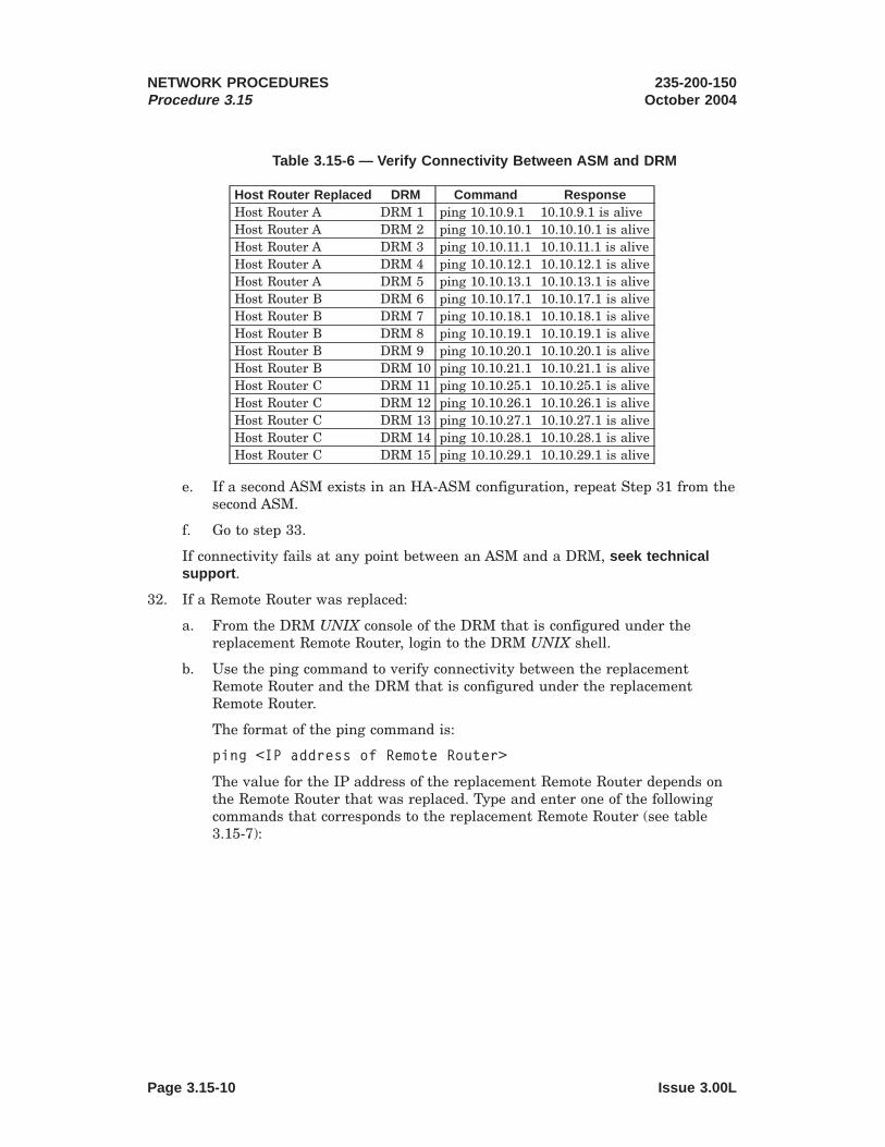
Table 3.15-6 — Verify Connectivity Between ASM and DRM
Host Router Replaced DRM Command ResponseHost Router A DRM 1 ping 10.10.9.1 10.10.9.1 is aliveHost Router A DRM 2 ping 10.10.10.1 10.10.10.1 is aliveHost Router A DRM 3 ping 10.10.11.1 10.10.11.1 is aliveHost Router A DRM 4 ping 10.10.12.1 10.10.12.1 is aliveHost Router A DRM 5 ping 10.10.13.1 10.10.13.1 is aliveHost Router B DRM 6 ping 10.10.17.1 10.10.17.1 is aliveHost Router B DRM 7 ping 10.10.18.1 10.10.18.1 is aliveHost Router B DRM 8 ping 10.10.19.1 10.10.19.1 is aliveHost Router B DRM 9 ping 10.10.20.1 10.10.20.1 is aliveHost Router B DRM 10 ping 10.10.21.1 10.10.21.1 is aliveHost Router C DRM 11 ping 10.10.25.1 10.10.25.1 is aliveHost Router C DRM 12 ping 10.10.26.1 10.10.26.1 is aliveHost Router C DRM 13 ping 10.10.27.1 10.10.27.1 is aliveHost Router C DRM 14 ping 10.10.28.1 10.10.28.1 is aliveHost Router C DRM 15 ping 10.10.29.1 10.10.29.1 is alive
e. If a second ASM exists in an HA-ASM configuration, repeat Step 31 from thesecond ASM.
f. Go to step 33.
If connectivity fails at any point between an ASM and a DRM, seek technicalsupport .
32. If a Remote Router was replaced:
a. From the DRM UNIX console of the DRM that is configured under thereplacement Remote Router, login to the DRM UNIX shell.
b. Use the ping command to verify connectivity between the replacementRemote Router and the DRM that is configured under the replacementRemote Router.
The format of the ping command is:
ping <IP address of Remote Router>
The value for the IP address of the replacement Remote Router depends onthe Remote Router that was replaced. Type and enter one of the followingcommands that corresponds to the replacement Remote Router (see table3.15-7):
NETWORK PROCEDURESProcedure 3.15
235-200-150October 2004
Page 3.15-10 Issue 3.00L

Table 3.15-7 — Verify Connectivity Between DRM and Remote Router
Remote Router Replaced Configured To DRM Command ResponseRemote Router 1 DRM 1 ping 10.10.9.254 10.10.9.254 is aliveRemote Router 2 DRM 2 ping 10.10.10.254 10.10.10.254 is aliveRemote Router 3 DRM 3 ping 10.10.11.254 10.10.11.254 is aliveRemote Router 4 DRM 4 ping 10.10.12.254 10.10.12.254 is aliveRemote Router 5 DRM 5 ping 10.10.13.254 10.10.13.254 is aliveRemote Router 6 DRM 6 ping 10.10.17.254 10.10.17.254 is aliveRemote Router 7 DRM 7 ping 10.10.18.254 10.10.18.254 is aliveRemote Router 8 DRM 8 ping 10.10.19.254 10.10.19.254 is aliveRemote Router 9 DRM 9 ping 10.10.20.254 10.10.20.254 is aliveRemote Router 10 DRM 10 ping 10.10.21.254 10.10.21.254 is aliveRemote Router 11 DRM 11 ping 10.10.25.254 10.10.25.254 is aliveRemote Router 12 DRM 12 ping 10.10.26.254 10.10.26.254 is aliveRemote Router 13 DRM 13 ping 10.10.27.254 10.10.27.254 is aliveRemote Router 14 DRM 14 ping 10.10.28.254 10.10.28.254 is aliveRemote Router 15 DRM 15 ping 10.10.29.254 10.10.29.254 is alive
c. Use the ping command to verify connectivity between the DRM that isconfigured under the replacement Remote Router and the correspondingHost Router.
The format of the ping command is:
ping <IP address of Host Router>
The value for the IP address of the Host Router depends on the RemoteRouter that was replaced. Type and enter one of the following commandsthat corresponds to the replacement Remote Router and its Host Router (seetable 3.15-8):
235-200-150October 2004
NETWORK PROCEDURESProcedure 3.15
Issue 3.00L Page 3.15-11

Table 3.15-8 — Verify Connectivity Between DRM and Host Router
Remote Router Replaced Host Router Command ResponseRemote Router 1 Host Router A ping 10.10.8.5 10.10.8.5 is aliveRemote Router 2 Host Router A ping 10.10.8.9 10.10.8.9 is aliveRemote Router 3 Host Router A ping 10.10.8.13 10.10.8.13 is aliveRemote Router 4 Host Router A ping 10.10.8.17 10.10.8.17 is aliveRemote Router 5 Host Router A ping 10.10.8.21 10.10.8.21 is aliveRemote Router 6 Host Router B ping 10.10.16.5 10.10.16.5 is aliveRemote Router 7 Host Router B ping 10.10.16.9 10.10.16.9 is aliveRemote Router 8 Host Router B ping 10.10.16.13 10.10.16.13 is aliveRemote Router 9 Host Router B ping 10.10.16.19 10.10.16.19 is aliveRemote Router 10 Host Router B ping 10.10.16.21 10.10.16.21 is aliveRemote Router 11 Host Router C ping 10.10.24.5 10.10.24.5 is aliveRemote Router 12 Host Router C ping 10.10.24.9 10.10.24.9 is aliveRemote Router 13 Host Router C ping 10.10.24.13 10.10.24.13 is aliveRemote Router 14 Host Router C ping 10.10.24.19 10.10.24.19 is aliveRemote Router 15 Host Router C ping 10.10.24.21 10.10.24.21 is alive
d. Type and enter the following command to verify connectivity between theDRM configured under the replacement Remote Router and the ASM:
ping 10.10.1.1
Where: 10.10.1.1 = the IP address of the ASM
Response:10.10.1.1 is alive
e. If a second ASM exists in an HA-ASM configuration, type and enter thefollowing command to verify connectivity between the DRM configured underthe replacement Remote Router and the second ASM:
ping 10.10.1.2
Where: 10.10.1.2 = the IP address of the second ASM
Response:10.10.1.2 is alive
If connectivity fails at any point between a DRM and an ASM, seek technicalsupport .
33. If a connection to the Supervisor Console is no longer desired, power down theconsole, and remove the cable from Port 6 of the Router.
34. STOP. YOU HAVE COMPLETED THIS PROCEDURE.
NETWORK PROCEDURESProcedure 3.15
235-200-150October 2004
Page 3.15-12 Issue 3.00L

Distinctive Remote Module (DRM)
CONTENTS PAGE
4. ADMINISTRATIVE WORKSTATION MAINTENANCE . . . . . . . . . 4-1
4.1 Halt the Administrative Module (AM) Emulator . . . . . . . . 4.1-1
4.2 Halt the Administrative Workstation . . . . . . . . . . . . 4.2-1
4.3 Restore Administrative Workstation . . . . . . . . . . . . 4.3-1
4.4 Backup Administrative Workstation Operating System . . . . . 4.4-1
4.5 Boot Administrative Workstation From Alternate Disk . . . . . 4.5-1
4.5.1 Replace a Defective Disk ( Netra t 1120) . . . . . . . . 4.5.1-1
4.5.2 Replace a Defective Secondary Disk ( Netra 20) . . . . . 4.5.2-1
4.5.3 Replace a Defective Primary Disk ( Netra 20) . . . . . . 4.5.3-1
4.5.4 Replace a Defective Primary Disk ( Netra 240). . . . . . 4.5.4-1
4.5.5 Replace a Defective Secondary Disk ( Netra 240) . . . . 4.5.5-1
4.5.6 Partition and Propagate the System to theNon-Active Disk . . . . . . . . . . . . . . . . . 4.5.6-1
4.5.7 Format the Secondary Disk from a Boot CD-ROM(Netra t 1120) . . . . . . . . . . . . . . . . . . 4.5.7-1
4.5.8 Format the Primary or Secondary Disk from a BootCD-ROM (Netra 20 or Netra 240) . . . . . . . . . . . 4.5.8-1
4.6 Replace System Unit ( Netra t 1120 or Netra 20) . . . . . . . . 4.6-1
4.7 Remove Power to Administrative Workstation ( Netra t 1120and Netra 20) . . . . . . . . . . . . . . . . . . . . . 4.7-1
4.8 Restore Power to Administrative Workstation ( Netra t 1120and Netra 20) . . . . . . . . . . . . . . . . . . . . . 4.8-1
4.9 Remove Power to Administrative Workstation Units ( Netra240) . . . . . . . . . . . . . . . . . . . . . . . . . 4.9-1
4.10 Restore Power to Administrative Workstation Units ( Netra240) . . . . . . . . . . . . . . . . . . . . . . . . . 4.10-1
4.11 Replace a DAT or CD-ROM/DVD Drive ( Netra t 1120) . . . . . . 4.11-1
4.12 Replace a DAT or DVD Drive ( Netra TM 20) . . . . . . . . . 4.12-1
235-200-150March 2006
ADMINISTRATIVE WORKSTATION MAINTENANCE
Issue 3.00M Page 4-i
4.12-1
4 . 1 1 - 1
4.10-1
4.9-1
4.8-1
4.7-1
4.6-1
4.5-1
4.4-1
4.3-1
4.2-1
4.1-1
4 - 1

4.13 Replace System Unit ( Netra 240). . . . . . . . . . . . . . 4.13-1
4.14 Replace a DAT Tape Drive Unit ( Netra 240) . . . . . . . . . . 4.14-1
4.15 Remove Power to DAT Tape Drive Unit ( Netra 240) . . . . . . 4.15-1
4.16 Restore Power to DAT Tape Drive Unit ( Netra 240) . . . . . . . 4.16-1
4.17 Replace a DVD Drive ( Netra 240). . . . . . . . . . . . . . 4.17-1
4.18 Replace a Power Supply Unit ( Netra 240) . . . . . . . . . . 4.18-1
4.19 Load Tape in DAT Tape Drive Unit . . . . . . . . . . . . . 4.19-1
4.20 Unload Tape from DAT Tape Drive Unit . . . . . . . . . . . 4.20-1
4.21 Emergency Tape Ejection ( Netra t 1120, Netra 20 and Netra240) . . . . . . . . . . . . . . . . . . . . . . . . . 4.21-1
4.22 Clean the DAT Tape Drive Unit Head . . . . . . . . . . . . 4.22-1
LIST OF FIGURES
Figure 4.5.1-1 — Hard Disk Drive Location . . . . . . . . . . . . . . 4.5.1-1
Figure 4.5.2-1 — Removal of the Netra 20 Hard Drives . . . . . . . . . 4.5.2-3
Figure 4.5.3-1 — Removal of the Netra 20 Hard Drives . . . . . . . . . 4.5.3-3
Figure 4.5.4-1 — Netra 240 Front Panel . . . . . . . . . . . . . . . 4.5.4-4
Figure 4.5.4-2 — Netra 240 Hard Drive LED Indicators . . . . . . . . . 4.5.4-4
Figure 4.5.4-3 — Netra 240 Disk Drive Access . . . . . . . . . . . . 4.5.4-5
Figure 4.5.5-1 — Netra 240 Front Panel . . . . . . . . . . . . . . . 4.5.5-4
Figure 4.5.5-2 — Netra 240 Hard Drive LED Indicators . . . . . . . . . 4.5.5-4
Figure 4.5.5-3 — Netra 240 Disk Drive Access . . . . . . . . . . . . 4.5.5-5
Figure 4.6-1 — Administrative Workstation Interface Configuration(Netra t 1120) . . . . . . . . . . . . . . . . . . . 4.6-2
Figure 4.6-2 — Administrative Workstation Interface Configuration(Netra 20) . . . . . . . . . . . . . . . . . . . . . 4.6-2
Figure 4.6-3 — Serial Asynchronous Interface (SAI) for Netra t 1120 . . . . 4.6-3
Figure 4.6-4 — Serial Asynchronous Interface (SAI) for Netra 20 . . . . . 4.6-3
Figure 4.6-5 — Quad Fast Ethernet - Netra t 1120 InterfaceConnections . . . . . . . . . . . . . . . . . . . 4.6-4
ADMINISTRATIVE WORKSTATION MAINTENANCE 235-200-150March 2006
Page 4-ii Issue 3.00M
4.6-4
4.6-3
4.6-3
4.6-2
4.6-2
4.22-1
4.21-1
4.20-1
4.19-1
4.18-1
4.17-1
4.16-1
4.15-1
4.14-1
4.13-1

Figure 4.6-6 — Quad Fast Ethernet - Netra 20 Interface Connections . . . . 4.6-4
Figure 4.6-7 — MCC Interface to Administrative Workstation - Netra t1120 . . . . . . . . . . . . . . . . . . . . . . . 4.6-5
Figure 4.6-8 — MCC Interface to Administrative Workstation - Netra 20. . . 4.6-6
Figure 4.6-9 — STLWS and ROP Interface - Netra 20 . . . . . . . . . . 4.6-6
Figure 4.6-10 — STLWS and ROP Interface - Netra t 1120 . . . . . . . . 4.6-7
Figure 4.6-11 — SCANS/AMA/SCCS/Optional OSS Interface - Netra t1120 . . . . . . . . . . . . . . . . . . . . . . 4.6-8
Figure 4.6-12 — SCANS/AMA/SCCS/Optional OSS Interface - Netra 20 . . . 4.6-8
Figure 4.6-13 — Hard Disk Drive Location . . . . . . . . . . . . . . 4.6-9
Figure 4.6-14 — Removal of the Netra 20 Hard Drives . . . . . . . . . 4.6-10
Figure 4.7-1 — Netra t 1120 Power Panel . . . . . . . . . . . . . . 4.7-1
Figure 4.7-2 — Netra 20 Power Panel . . . . . . . . . . . . . . . . 4.7-2
Figure 4.7-3 — Administrative Workstation Interface Configuration(Netra t 1120) . . . . . . . . . . . . . . . . . . . 4.7-3
Figure 4.7-4 — Administrative Workstation Interface Configuration(Netra 20) . . . . . . . . . . . . . . . . . . . . . 4.7-3
Figure 4.8-1 — Administrative Workstation Interface Configuration(Netra t 1120) . . . . . . . . . . . . . . . . . . . 4.8-1
Figure 4.8-2 — Administrative Workstation Interface Configuration(Netra 20) . . . . . . . . . . . . . . . . . . . . . 4.8-2
Figure 4.8-3 — Netra t 1120 Power Panel . . . . . . . . . . . . . . 4.8-2
Figure 4.8-4 — Netra 20 Power Panel . . . . . . . . . . . . . . . . 4.8-3
Figure 4.11-1 — Removal of the Netra t 1120 Top Cover . . . . . . . . . 4.11-1
Figure 4.11-2 — Removal of the Netra t 1120 CDROM/DVD and DATDrive . . . . . . . . . . . . . . . . . . . . . . 4.11-2
Figure 4.12-1 — Removal of Netra 20 Top Cover . . . . . . . . . . . . 4.12-1
Figure 4.12-2 — Removal of Netra 20 DAT or DVD . . . . . . . . . . . 4.12-2
Figure 4.13-1 — NETRA 240 Front Fingerholds . . . . . . . . . . . . 4.13-2
Figure 4.13-2 — NETRA 240 Disk Drive . . . . . . . . . . . . . . . 4.13-3
Figure 4.14-1 — NETRA 240 DAT Rear Panel . . . . . . . . . . . . . 4.14-1
235-200-150March 2006
ADMINISTRATIVE WORKSTATION MAINTENANCE
Issue 3.00M Page 4-iii
4.14-1
4.13-3
4.13-2
4.12-2
4.12-1
4 . 1 1 - 2
4 . 1 1 - 1
4.8-3
4.8-2
4.8-2
4.8-1
4.7-3
4.7-3
4.7-2
4.7-1
4.6-10
4.6-9
4.6-8
4.6-8
4.6-7
4.6-6
4.6-6
4.6-5
4.6-4

Figure 4.14-2 — NETRA 240 DAT Front Panel . . . . . . . . . . . . . 4.14-2
Figure 4.15-1 — NETRA 240 DAT Rear Panel . . . . . . . . . . . . . 4.15-1
Figure 4.15-2 — NETRA 240 DAT DC Power Connections . . . . . . . . 4.15-2
Figure 4.16-1 — NETRA 240 DAT Rear Panel . . . . . . . . . . . . . 4.16-1
Figure 4.16-2 — NETRA 240 DAT DC Power Connections . . . . . . . . 4.16-2
Figure 4.17-1 — NETRA 240 Front Fingerholds . . . . . . . . . . . . 4.17-1
Figure 4.17-2 — NETRA 240 Front Fingerholds . . . . . . . . . . . . 4.17-2
Figure 4.18-1 — Netra 240 Power Supply . . . . . . . . . . . . . . 4.18-2
LIST OF TABLES
Table 4-1 — Tape Format and Size Capacity . . . . . . . . . . . . . 4-2
Table 4.5-1 — AW Disk Drive Device IDs . . . . . . . . . . . . . . . 4.5-1
ADMINISTRATIVE WORKSTATION MAINTENANCE 235-200-150March 2006
Page 4-iv Issue 3.00M
4.5-1
4 - 2
4.18-2
4.17-2
4.17-1
4.16-2
4.16-1
4.15-2
4.15-1
4.14-2

4. ADMINISTRATIVE WORKSTATION MAINTENANCE
Overview
This chapter covers maintenance of the Netra1 t 1120, Netra 20 and Netra 240(Administrative Workstation) located at the DRM office. Although procedure stepsinvolving software commands can be performed via the ASM (via an OA&Mcut-through), someone must be present at the DRM office to perform any hardwareportions. The Administrative Workstation (AW) requires very little correctivemaintenance and no routine maintenance.
In the event of a complete workstation failure, the entire AW should be replaced. Inthe rare case of a duplex hard disk failure, both hard disks must be replaced. Once thenew workstation is installed with the appropriate interface cable connections, thesoftware must be reloaded from backup tapes (created and kept current after theinitial installation) and the SunOS + emulator tape or CD-ROM (accompanied theinitial switch installation).
The following tapes and CD-ROM were provided with the switch hardware andcontain all the necessary software to operate the switch:
1. SUN OS + Emulator - contains the SUN OS software and the 3B21 emulatorsoftware resident on the AW (provided during switch installation).
2. TOP (Tape Operating Procedure) - contains the necessary tape loading software.
3. Switching Module Text - contains the switching module text data normallyresident in the switching module.
4. AM Text - Contains the emulated Administrative Module (AM) text data. Theremay be 1 or 2 AM text tapes.
5. AM ODD/ECD - Contains the emulated AM Office Dependent Data (ODD) andthe necessary Equipment Configuration Database (ECD).
6. Switching Module ODD - Contains the switching module ODD necessary for callprocessing.
Note: Tapes 2 through 6 provided for installation will NOT work for office recoveryresulting from workstation replacement. These tapes must be made after initialinstallation and kept current using the backup procedures in 235-105-210, 5ESS®
Switch Routine Operations and Maintenance Procedures.
See “Perform Office Dead Start Recovery,” Procedure 7.1, for loading the software fromthe tape to the AW.
Digital Audio Tape (DAT) Tape Drive Unit
The Digital Audio Tape (DAT) tape drive unit connected to or built into the AWprovides permanent storage for switch data. The DAT tape drive unit uses a tapecassette that loads and unloads from the unit in a simple manner.
The DAT tape drive unit is designed to use 4mm data-grade DDS cartridge media.Look for the DDS label on the tape cartridge to be sure you are using data-grade tapeand not audio-grade tape. The tape cartridge should be of the same temperature asthe drive for 24 hours prior to use. Table 4-1 lists the format and supported tape sizesand tape capacities in native (non-compressed) mode.
1. Trademark of Sun Microsystems, Inc.
235-200-150March 2006
ADMINISTRATIVE WORKSTATION MAINTENANCE
Issue 3.00M Page 4-1

Table 4-1 — Tape Format and Size Capacity
Format Tape Size/CapacityDDS-1ab 60 meter/1.3 gbytes, 90 meter/2 gbytesDDS-2b 90 meter/2 gbytes, 120 meter/4 gbytesDDS-3 90 meter/2 gbytes, 120 meter/4 gbytes, 125
meter/12 gbytesDDS-4 90 meter/2 gbytes, 120 meter/4 gbytes, 125
meter/12 gbytes, 150 meter/20 gbytesDAT72 125 meter/12 gbytes, 150 meter/20 gbytes ,
170 meter/36 gbytesNote(s):
a. The Netra 20 DDS-4 DAT drive can read DDS-1 formatted tapes but cannot writeDSS-1 formatted tapes.
b. The Netra 240 DAT72 drive does not support DDS-1 or DDS-2 formatted tapes.
When handling and storing tape cartridges, observe the following precautions:
• Keep cartridges away from anything magnetic.
• Store in a clean, dust-free environment, upright on edge rather than flat.
• Store in protective covers when not in use.
• Keep out of direct sunlight and away from extreme heat, cold or humidity.
• Cartridge must be at room temperature before using.
• Never open the tape access door on the cartridge and touch the magneticrecording surface.
To maintain reliability in the DAT tape drive unit, regular head cleaning is required.After every 25 hours of tape operation the unit should be cleaned using a DDScleaning cartridge. See “Clean the DAT Tape Drive Unit Head,” Procedure 4.22.
ADMINISTRATIVE WORKSTATION MAINTENANCE 235-200-150March 2006
Page 4-2 Issue 3.00M
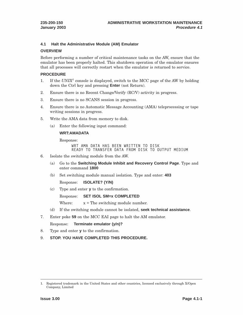
4.1 Halt the Administrative Module (AM) Emulator
OVERVIEW
Before performing a number of critical maintenance tasks on the AW, ensure that theemulator has been properly halted. This shutdown operation of the emulator ensuresthat all processes will correctly restart when the emulator is returned to service.
PROCEDURE
1. If the UNIX1 console is displayed, switch to the MCC page of the AW by holdingdown the Ctrl key and pressing Enter (not Return).
2. Ensure there is no Recent Change/Verify (RC/V) activity in progress.
3. Ensure there is no SCANS session in progress.
4. Ensure there is no Automatic Message Accounting (AMA) teleprocessing or tapewriting sessions in progress.
5. Write the AMA data from memory to disk.
(a) Enter the following input command:
WRT:AMADATA
Response:WRT AMA DATA HAS BEEN WRITTEN TO DISKREADY TO TRANSFER DATA FROM DISK TO OUTPUT MEDIUM
6. Isolate the switching module from the AW.
(a) Go to the Switching Module Inhibit and Recovery Control Page . Type andenter command 1800
(b) Set switching module manual isolation. Type and enter: 403
Response: ISOLATE? (Y/N)
(c) Type and enter y to the confirmation.
Response: SET ISOL SM=x COMPLETED
Where: x = The switching module number.
(d) If the switching module cannot be isolated, seek technical assistance .
7. Enter poke 59 on the MCC EAI page to halt the AM emulator.
Response: Terminate emulator (y/n)?
8. Type and enter y to the confirmation.
9. STOP. YOU HAVE COMPLETED THIS PROCEDURE.
1. Registered trademark in the United States and other countries, licensed exclusively through X/OpenCompany, Limited
235-200-150January 2003
ADMINISTRATIVE WORKSTATION MAINTENANCEProcedure 4.1
Issue 3.00 Page 4.1-1


4.2 Halt the Administrative Workstation
OVERVIEW
Before performing any type of maintenance on the AW, ensure that the workstationhas been properly halted. This shutdown operation for the software ensures that allprocesses will correctly restart when the workstation is returned to service.
PROCEDURE
1. Halt the AM emulator.
Note: These are the same procedures as outlined in “Halt the AdministrativeModule (AM) Emulator,” Procedure 4.1.
(a) If the UNIX1 console is displayed, switch to the MCC page of the AW byholding down the Ctrl key and pressing Enter (not Return).
(b) Ensure there is no Recent Change/Verify (RC/V) activity in progress.
(c) Ensure there is no SCANS session in progress.
(d) Ensure there is no Automatic Message Accounting (AMA) teleprocessing ortape writing sessions in progress.
(e) Write the AMA data from memory to disk.
a. Enter the following input command:
WRT:AMADATA
WRT AMA DATA HAS BEEN WRITTEN TO DISKREADY TO TRANSFER DATA FROM DISK TO OUTPUT MEDIUM
(f) Isolate the switching module from the AW.
a. Go to the Switching Module Inhibit and Recovery Control Page . Typeand enter command 1800
b. Set switching module manual isolation. Type and enter: 403
Response: ISOLATE? (Y/N)
c. Type and enter y to the confirmation.
Response: SET ISOL SM=x COMPLETED
Where: x = The switching module number.
d. If the switching module cannot be isolated, seek technical assistance .
(g) Enter poke 59 on the MCC EAI page to halt the AM emulator.
Response: Terminate emulator (y/n)?
(h) Type and enter y to the confirmation.
2. Switch to the UNIX console of the AW by holding down the Ctrl key and pressingEnter (not Return) on the MCC.
3. If a login prompt does not appear, press Return repeatedly until one appears.
4. At the login prompt, login as awadmin , for example:
1. Registered trademark in the United States and other countries, licensed exclusively through X/OpenCompany, Limited
235-200-150October 2005
ADMINISTRATIVE WORKSTATION MAINTENANCEProcedure 4.2
Issue 3.00B Page 4.2-1

attaws console login: awadmin
5. From the Administrative Workstation Main Menu, select "Halt the Workstation,”Answer yes to the confirmation. If you select a task by mistake, answer no to theconfirmation, and the main menu will return.
Response:You have chosen to halt the workstation. If the emulator is running,it must be halted before continuing. Refer to the main menu item ofHalt the Emulator.
Do you want to continue (yes/no) yes
6. Wait for one of the following prompts. When one of these prompts appears, theworkstation has been successfully halted.
Program Terminated
Type help for more information
ok
7. STOP. YOU HAVE COMPLETED THIS PROCEDURE.
ADMINISTRATIVE WORKSTATION MAINTENANCEProcedure 4.2
235-200-150October 2005
Page 4.2-2 Issue 3.00B

4.3 Restore Administrative Workstation
OVERVIEW
This procedure provides the steps to take when the AW locks up and fails to respondto input commands or pokes entered on the MCC terminal.
The following items could cause the AW to lock up:
• The MCC terminal is powered down
• A Reset/Break key or key sequence is inadvertently entered
• The cables between the MCC and the AW are detached.
This procedure contains steps to restore the AW to operation.
PROCEDURE
1. Verify the MCC terminal is powered on and is properly connected to the Sun1
workstation.
2. If an MCC page is displayed, switch to the UNIX2 console of the AW by holdingdown the Ctrl key and pressing Enter (not Return).
3. Press the RETURN key several times.
If the "ok" prompt appears, proceed to Step 4.
If a "console login:" appears, proceed to Step 9.
4. Type and enter go and press the RETURN key.
Note: May need to type go twice
5. If the "console login:" prompt then appears, switch back to the MCC by holdingdown the Ctrl key and pressing Enter (not Return).
6. If the response is "Program terminated," at the "ok" prompt, type and enter: boot
7. Wait for the boot sequence to complete then switch back to the MCC by holdingdown the Ctrl key and pressing Enter (not Return).
8. Does the MCC now accept input commands and pokes?
If YES, STOP. YOU HAVE COMPLETED THIS PROCEDURE .
If NO, continue.
9. At the login prompt, log in as awadmin , for example.console login: awadmin
10. From the Administrative Workstation Main Menu, select “Boot the Workstation”.Answer yes to the confirmation. If you select a task by mistake, answer no to theconfirmation.
Response:You have chose to boot the workstation. If the Emulator is running,it must be halted before continuing. Refer to the Main Menu ite ofHalt the Emulator.
1. Registered trademark of Sun Microsystems, Inc.2. Registered trademark in the United States and other countries, licensed exclusively through X/Open
Company, Limited
235-200-150January 2003
ADMINISTRATIVE WORKSTATION MAINTENANCEProcedure 4.3
Issue 3.00 Page 4.3-1

Do you want to continue (yes/no) yes
11. Wait for the boot sequence to complete and then switch back to the MCC byholding down the Ctrl key and pressing Enter (not Return).
12. Does the MCC now accept input commands and pokes?
If YES, STOP. YOU HAVE COMPLETED THIS PROCEDURE .
If NO, contact the next level of technical support.
ADMINISTRATIVE WORKSTATION MAINTENANCEProcedure 4.3
235-200-150January 2003
Page 4.3-2 Issue 3.00

4.4 Backup Administrative Workstation Operating System
OVERVIEW
This procedure should be run following an update to the AW operating system or the3B21 emulator. This procedure should be used whenever a software update is appliedwhich has TARGET=EMULATOR .
PROCEDURE
1. If an MCC page is displayed, switch to the UNIX1 console of the AW, by holdingdown the Ctrl key and pressing Enter (not Return) on the MCC.
2. If a login prompt does not appear, press Return repeatedly until one appears.
3. At the login prompt, login as awadmin , for example:
console login: awadmin
4. From the Administrative Workstation Main Menu, select "Backup theworkstation Operating System/Emulator to disk.” (If you select a task bymistake, answer no to the confirmation, and the main menu will return.)
5. From the Operating System/Emulator Backup to Secondary Disk Menu, select"Execute backup of the workstation Operating System/Emulator to disk." Answeryes to the confirmation.
Response:You have chosen to backup the workstation Operating System/Emulator todisk.
Do you want to continue? (yes/no) yes
This task takes about 15 minutes
6. If the AW is a Netra2 t 1120, answer no to the following response:
Response:Do you want to set the secondary disk bootable? no
If the AW is a Netra 20 or Netra 240 and the AW is running on the primary disk,answer yes to the following response:
Response:Do you want to set the secondary disk bootable? yes
When completed, you will be prompted to press [RETURN]. When the promptappears press [RETURN] or [ENTER] on the alpha keyboard.
7. If you wish to view the output of this OS backup, select "View output from themost recent operating system/emulator backup to disk." While viewing theoutput, use the following keys:
1. Registered trademark in the United States and other countries, licensed exclusively through X/OpenCompany, Limited
2. Registered trademark of Sun Microsystems, Inc.
235-200-150October 2005
ADMINISTRATIVE WORKSTATION MAINTENANCEProcedure 4.4
Issue 3.00H Page 4.4-1

space see the next screen of outputb see the previous screen of outputh see a list of available keysq quit viewing output
8. Select "Return to main menu."
9. If the Administrative Workstation Operating System is only being backed up todisk, proceed to step 10.
If the Administrative Workstation Operating System is to be backed up to tape,proceed with step 12.
10. From the main menu, select "Exit."
11. STOP. YOU HAVE COMPLETED THIS PROCEDURE.
12. Insert a 4mm tape that may be overwritten into the DAT tape drive unit using“Load Tape in DAT Tape Drive Unit,” Procedure 4.19.
13. From the main menu , select "Backup the workstation operating system/emulatorto Tape."
14. From the Operating System/Emulator backup to tape menu, select "Executebackup of the workstation Operating System/Emulator to tape." Answer yes tothe confirmation. If you select a task by mistake, answer no to the confirmation.
Response:You have chosen to backup the workstation Operating System/Emulator totape. Please ensure that there is a 4mm tape cartridge in the DigitalAudio Tape (DAT) drive.
Do you want to continue? (yes/no) yes
This task will take approximately 20 minutes. When it is completed, you will beprompted to press Return. When the prompt appears, press Return.
15. If you wish to view the output of this OS backup to tape, select "View outputfrom the most recent operating system/emulator backup to tape." While viewingthe output, use the following keys:
space see the next screen of outputb see the previous screen of outputh see a list of available keysq quit viewing output
16. Select "Return to the main menu."
17. From the main menu, select "Exit."
18. Unload the 4mm tape from the DAT tape drive unit using the procedure “UnloadTape from DAT Tape Drive Unit,” Procedure 4.20. Be sure to protect the tapefrom being accidentally overwritten by sliding the white write-protect tab to thewrite protection side.
ADMINISTRATIVE WORKSTATION MAINTENANCEProcedure 4.4
235-200-150October 2005
Page 4.4-2 Issue 3.00H

19. Label the tape with the following information:
Date:__________________________Generic:_______________________BWM Level:____________________Tape Type: Emulator and Sun OSTape Seq Number:______________Comments:_____________________
The workstation operating system/emulator has been successfully backed up.
20. STOP. YOU HAVE COMPLETED THIS PROCEDURE.
235-200-150October 2005
ADMINISTRATIVE WORKSTATION MAINTENANCEProcedure 4.4
Issue 3.00H Page 4.4-3


4.5 Boot Administrative Workstation From Alternate Disk
OVERVIEW
This procedure should be used to replace a defective disk drive on the AW. On theNetra1 t 1120, Netra 20 and Netra 240 both the primary disk and the secondary diskare internal drives. It is assumed that the secondary disk has been kept in sync withthe primary drive by performing a backup to it recently. Table 4.5-1 lists the deviceIDs for the AW disk drives.
Table 4.5-1 — AW Disk Drive Device IDs
Workstation Disk Interface Primary Disk ID Secondary DiskID
Netra t 1120 SCSI 0 1Netra 20 Fiber Channel 0 1Netra 240 SCSI 0 1
PROCEDURE
1. Replace a Defective Disk (see Subprocedure 4.5.1 for Netra t 1120).
2. Replace a Defective Secondary Disk (see Subprocedure 4.5.2 for the Netra 20).
3. Replace a Defective Primary Disk (see Subprocedure 4.5.3 for the Netra 20).
4. Replace a Defective Primary Disk (see Subprocedure 4.5.4 for the Netra 240).
5. Replace a Defective Secondary Disk (see Subprocedure 4.5.5 for the Netra 240).
6. Partition and Propagate the System to the Non-Active Disk (see Subprocedure4.5.6).
1. Trademark of Sun Microsystems, Inc.
235-200-150October 2005
ADMINISTRATIVE WORKSTATION MAINTENANCEProcedure 4.5
Issue 3.00B Page 4.5-1


4.5.1 Replace a Defective Disk ( Netra1 t 1120)
OVERVIEW
This procedure is used to replace a defective disk drive in the AdministrativeWorkstation (AW).
Note: If the primary disk drive is being replaced, this procedure assumes that thesecondary disk drive contains a backup of the 3B Emulator and Solaris OperatingSystem software. The secondary disk drive will replace the primary disk drive and thereplacement disk drive will be installed as the secondary disk.
Caution: Follow proper ESD grounding procedures when handling AW units.Wear an antistatic wrist strap. Handle disk drives by their sides and storeESD-sensitive components in antistatic containers.
PROCEDURE
1. Remove power to the AW. See "Remove Power to Administrative Workstation(Netra t 1120 and Netra 20)", Procedure 4.7.
2. Open the front access cover by twisting the two locking rings counter clockwise tothe open position and lowering the front cover.
Remove the front ESD plate (See Figure 4.5.1-1). With a No.1 Phillips-headscrewdriver, remove the captive screws.
3. Remove the secondary disk drive from the upper disk drive slot by pushing thelatch to the right, extending the drive handle, and pulling the disk from the drivebay.
4. Is the primary disk drive being replaced?
1. Trademark of Sun Microsystems, Inc.
Figure 4.5.1-1 — Hard Disk Drive Location
235-200-150March 2006
ADMINISTRATIVE WORKSTATION MAINTENANCEProcedure 4.5.1
Issue 3.00M Page 4.5.1-1

If YES, continue with Step 5.
If NO, skip to Step 7.
5. Remove the primary disk drive from the lower disk drive slot by pushing thelatch to the right, extending the drive handle, and pulling the disk from the drivebay.
6. Install the secondary disk drive removed in step 3 into the lower disk drive slot;pushing the disk into the drive bay until contact is made with the backplaneconnector. Push the drive handle to lock the drive into the system.
7. Install the replacement disk drive in the upper disk drive slot; pushing the diskinto the drive bay until contact is made with the backplane connector. Push thedrive handle to lock the drive into the system.
8. Replace the front ESD plate using a No.1 Phillips-head screwdriver to tightenthe three retaining screws holding the ESD plate.
9. Replace the front access cover by lifting into place against the AW chassis andtwisting the two locking rings clockwise to the lock position.
10. Restore power to the AW. See "Restore Power to Administrative Workstation(Netra t 1120 and Netra 20)", Procedure 4.8.
11. Is the system booted and running the emulated AM environment?
If YES, proceed with Step 12.
If NO, seek technical assistance .
12. Proceed to "Partition and Propagate the System to the Non-Active Disk,"Subprocedure 4.5.6
13. STOP. YOU HAVE COMPLETED THIS PROCEDURE.
ADMINISTRATIVE WORKSTATION MAINTENANCEProcedure 4.5.1
235-200-150March 2006
Page 4.5.1-2 Issue 3.00M

4.5.2 Replace a Defective Secondary Disk ( Netra1 20)
PROCEDURE
Note: This procedure requires a replacement disk to be available.
1. At the login prompt, login as root.
2. Execute the mount command and determine which Solaris disk the system isrunning on. If the output from the mount command shows the root partition as /on /dev/dsk/c1t0d0s0 , the system is running on the primary disk. If the rootpartition is shown as / on /dev/dsk/c1t1d0s0, the system is running on thesecondary disk.
3. Is the system running on the primary Solaris disk?
If YES, proceed with Step 6.
If NO, proceed with Step 4.
4. Is the AW stable enough to login?
If YES, stop the AW. See “Halt the Administrative Workstation”, procedure 4.2.
If NO, and the system is not at the ok prompt, enter ~^B (tilde control b).
5. Boot the system on the primary disk by entering boot disk0 at the ok prompt.
6. If AM emulator is running, halt it following procedure 4.1, “Halt theAdministrative Module (AM) Emulator”.
7. At the login prompt, login as awadmin
8. From the Administrative Workstation Main Menu, select “Change OperatingSystem booting disk”. If given multiple disks to choose from, select task “1” to setthe primary disk as the default boot disk:
Response:1) Change the Workstation Default Boot Disk to Primary Disk2) Change the Workstation Default Boot Disk to Secondary Disk3) Return to the Main Menu
Select task by number (1-3): 1
If prompted to set the primary disk as the default boot disk, enter yes :
Response:Do you want to change the default boot device to the primary disk(disk0)? yes
If prompted to set the secondary disk as the default boot disk, enter no :
Response:Do you want to change the default boot device to the secondary disk(disk1)? no
9. When prompted, enter return to continue.
10. From the Administrative Workstation Main Menu, select “Exit”
11. At the login prompt, login as root.
1. Trademark of Sun Microsystems, Inc.
235-200-150October 2005
ADMINISTRATIVE WORKSTATION MAINTENANCEProcedure 4.5.2
Issue 3.00B Page 4.5.2-1

12. Enter the following command to set the system crash dump device to the primarydisk.dumpadm -d /dev/dsk/c1t0d0s1
13. Enter luxadm remove_device /dev/rdsk/c1t1d0s2 . If the following response isreceived, enter “c” to continue. If this response is not received, seek technicalassistance.
WARNING!!! Please ensure that no filesystems are mounted on these device(s).All data on these devices should have been backed up.
The list of devices which will be removed is:1: Device name: /dev/rdsk/c1t1d0s2
Node WWN: [unique WWN number for the disk unit]Device Type:Disk deviceDevice Paths:/dev/rdsk/c1t1d0s2
Please verify the above list of devices andthen enter ’c’ or ⟨CR⟩ to Continue or ’q’ to Quit. [Default: c]
14. When prompted with the following response to remove the disk, continue withstep 15. If this response is not received, seek technical assistance .
Response:stopping: /dev/rdsk/c1t1d0s2....Doneofflining: /dev/rdsk/c1t1d0s2....Done
Hit ⟨Return⟩ after removing the device(s).
15. Remove the front fascia from the workstation.
16. Locate the LED for the HDD (Hard Disk Drive) on the panel. Refer to Figure4.5.2-1.
ADMINISTRATIVE WORKSTATION MAINTENANCEProcedure 4.5.2
235-200-150October 2005
Page 4.5.2-2 Issue 3.00B

17. Verify that the blue light indicating the disk can be removed is lit.
Note: If the Blue light does not light with 2 minutes after completing step 13,seek technical assistance .
18. Remove HDD1 (right disk).
a. Push the disk drive latch downwards to release the drive handle.
b. Extend the drive handle to disconnect the drive from the system.
c. Holding the drive handle, remove the drive from the drive bay.
19. Enter return at the console prompt. If the following response is not received, seektechnical assistance .Device: /dev/rdsk/c1t1d0s2Logical Nodes being removed under /dev/dsk/ and
/dev/rdsk:c1t1d0s0c1t1d0s1c1t1d0s2c1t1d0s3c1t1d0s4c1t1d0s5c1t1d0s6c1t1d0s7
Figure 4.5.2-1 — Removal of the Netra 20 Hard Drives
235-200-150October 2005
ADMINISTRATIVE WORKSTATION MAINTENANCEProcedure 4.5.2
Issue 3.00B Page 4.5.2-3
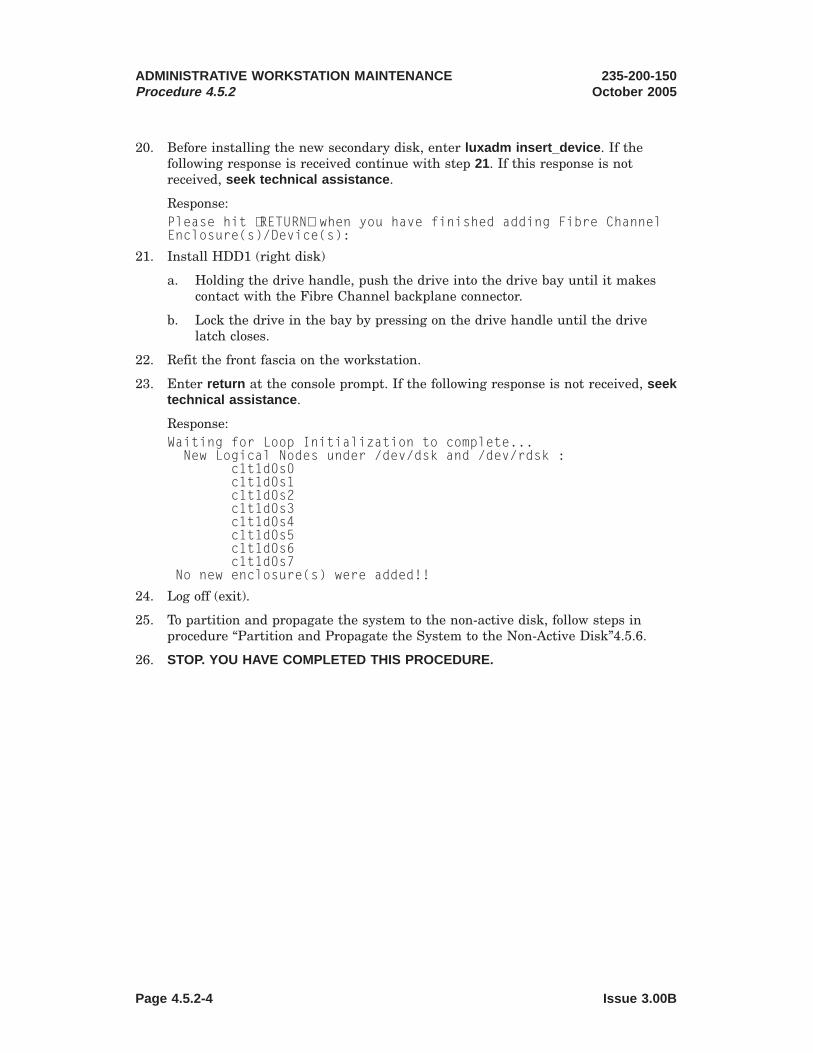
20. Before installing the new secondary disk, enter luxadm insert_device . If thefollowing response is received continue with step 21. If this response is notreceived, seek technical assistance .
Response:Please hit ⟨RETURN⟩ when you have finished adding Fibre ChannelEnclosure(s)/Device(s):
21. Install HDD1 (right disk)
a. Holding the drive handle, push the drive into the drive bay until it makescontact with the Fibre Channel backplane connector.
b. Lock the drive in the bay by pressing on the drive handle until the drivelatch closes.
22. Refit the front fascia on the workstation.
23. Enter return at the console prompt. If the following response is not received, seektechnical assistance .
Response:Waiting for Loop Initialization to complete...New Logical Nodes under /dev/dsk and /dev/rdsk :
c1t1d0s0c1t1d0s1c1t1d0s2c1t1d0s3c1t1d0s4c1t1d0s5c1t1d0s6c1t1d0s7
No new enclosure(s) were added!!
24. Log off (exit).
25. To partition and propagate the system to the non-active disk, follow steps inprocedure “Partition and Propagate the System to the Non-Active Disk”4.5.6.
26. STOP. YOU HAVE COMPLETED THIS PROCEDURE.
ADMINISTRATIVE WORKSTATION MAINTENANCEProcedure 4.5.2
235-200-150October 2005
Page 4.5.2-4 Issue 3.00B

4.5.3 Replace a Defective Primary Disk ( Netra1 20)
PROCEDURE
Note: This procedure requires a replacement disk to be available.
1. At the login prompt, login as root.
2. Execute the mount command and determine which Solaris disk the system isrunning on. If the output from the mount command shows the root partition as /on /dev/dsk/c1t0d0s0 , the system is running on the primary disk. If the rootpartition is shown as / on /dev/dsk/c1t1d0s0, the system is running on thesecondary disk.
3. Is the system running on the secondary Solaris disk?
If YES, proceed with Step 6.
If NO, proceed with Step 4.
4. Is the AW stable enough to login?
If YES, stop the AW. See “Halt the Administrative Workstation”, procedure 4.2.
If NO, and the system is not at the ok prompt, enter ~^B (tilde control b).
5. Boot the system on the secondary disk by entering boot disk1 at the ok prompt.
6. If AM emulator is running, halt it following procedure 4.1, “Halt theAdministrative Module (AM) Emulator”.
7. At the login prompt, login as awadmin
8. From the Administrative Workstation Main Menu, select “Change OperatingSystem booting disk”. If given multiple disks to choose from, select task “2” to setthe secondary disk as the default boot disk:
Response:1) Change the Workstation Default Boot Disk to Primary Disk2) Change the Workstation Default Boot Disk to Secondary Disk3) Return to the Main Menu
Select task by number (1-3): 2
If prompted to set the primary disk as the default boot disk, enter no :
Response:Do you want to change the default boot device to the primary disk(disk0)? no
If prompted to set the secondary disk as the default boot disk, enter yes :
Response:Do you want to change the default boot device to the secondary disk(disk1)? yes
9. When prompted, enter return to continue.
10. From the Administrative Workstation Main Menu, select “Exit”
11. At the login prompt, login as root .
1. Trademark of Sun Microsystems, Inc.
235-200-150October 2005
ADMINISTRATIVE WORKSTATION MAINTENANCEProcedure 4.5.3
Issue 3.00B Page 4.5.3-1

12. Enter the following command to set the system crash dump device to thesecondary disk.dumpadm -d /dev/dsk/c1t1s0s1
13. Enter luxadm remove_device /dev/rdsk/c1t0s0s2 . If the following response isreceived, enter “c” to continue. If this response is not received, seek technicalassistance.
Response:WARNING!!! Please ensure that no filesystems are mounted on these device(s).All data on these devices should have been backed up.
The list of devices which will be removed is:1: Device name: /dev/rdsk/c1t0s0s2
Node WWN: [unique WWN number for the disk unit]Device Type:Disk deviceDevice Paths:/dev/rdsk/c1t0s0s2
Please verify the above list of devices andthen enter ’c’ or ⟨CR⟩ to Continue or ’q’ to Quit. [Default: c]
14. When prompted with the following response to remove the disk, continue withstep 15. If this response is not received, seek technical assistance .
Response:stopping: /dev/rdsk/c1t0s0s2....Doneofflining: /dev/rdsk/c1t0s0s2....Done
Hit ⟨Return⟩ after removing the device(s).
15. Remove the front fascia from the workstation.
16. Locate the LED for the HDD (Hard Disk Drive) on the panel. Refer to Figure4.5.3-1.
ADMINISTRATIVE WORKSTATION MAINTENANCEProcedure 4.5.3
235-200-150October 2005
Page 4.5.3-2 Issue 3.00B

17. Verify that the blue light indicating the disk can be removed is lit.
Note: If the Blue light does not light with 2 minutes after completing step 13,seek technical assistance .
18. Remove HDD0 (left disk).
a. Push the disk drive latch downwards to release the drive handle.
b. Extend the drive handle to disconnect the drive from the system.
c. Holding the drive handle, remove the drive from the drive bay.
19. Enter return at the console prompt. If the following response is not received, seektechnical assistance .Device: /dev/rdsk/c1t0d0s2Logical Nodes being removed under /dev/dsk/ and
/dev/rdsk:c1t0d0s0c1t0d0s1c1t0d0s2c1t0d0s3c1t0d0s4c1t0d0s5c1t0d0s6c1t0d0s7
Figure 4.5.3-1 — Removal of the Netra 20 Hard Drives
235-200-150October 2005
ADMINISTRATIVE WORKSTATION MAINTENANCEProcedure 4.5.3
Issue 3.00B Page 4.5.3-3

20. Before installing the new primary disk, enter luxadm insert_device . If thefollowing response is received continue with step 21. If this response is notreceived, seek technical assistance .
Response:Please hit ⟨RETURN⟩ when you have finished adding Fibre ChannelEnclosure(s)/Device(s):
21. Install HDD0 (left disk)
a. Holding the drive handle, push the drive into the drive bay until it makescontact with the Fibre Channel backplane connector.
b. Lock the drive in the bay by pressing on the drive handle until the drivelatch closes.
22. Refit the front fascia on the workstation.
23. Enter return at the console prompt. If the following response is not received, seektechnical assistance .
Response:Waiting for Loop Initialization to complete...New Logical Nodes under /dev/dsk and /dev/rdsk :
c1t0d0s0c1t0d0s1c1t0d0s2c1t0d0s3c1t0d0s4c1t0d0s5c1t0d0s6c1t0d0s7
No new enclosure(s) were added!!
24. Log off (exit).
25. To partition and propagate the system to the non-active disk, follow steps inprocedure “Partition and Propagate the System to the Non-Active Disk”4.5.6.
26. At the login prompt, login as awadmin.
27. From the Administrative Workstation Main Menu, select “Change OperatingSystem booting disk”. If given multiple disks to choose from, select task “1” to setthe secondary disk as the default boot disk:
Response:1) Change the Workstation Default Boot Disk to Primary Disk2) Change the Workstation Default Boot Disk to Secondary Disk3) Return to the Main Menu
Select task by number (1-3): 1
If prompted to set the primary disk as the default boot disk, enter yes :
Response:Do you want to change the default boot device to the primary disk(disk0)? yes
If prompted to set the secondary disk as the default boot disk, enter no :
Response:
ADMINISTRATIVE WORKSTATION MAINTENANCEProcedure 4.5.3
235-200-150October 2005
Page 4.5.3-4 Issue 3.00B
Do you want to change the default boot device to the secondary disk(disk1)? no
28. When prompted, enter return to continue.
29. From the Administrative Workstation Main Menu, select "Boot the Workstation”.Answer yes to the confirmation. If you select a task by mistake, answer no to theconfirmation.You have chosen to boot the workstation. If the Emulator is running,it must be halted before continuing. Refer to the Main Menu item ofHalt the Emulator.
Do you want to continue? (yes/no) yes
The AW will boot on the primary disk and automatically start the AM emulator.
30. Is the system booted and running the emulated AM environment?
If YES, proceed with Step 31.
If NO, seek technical assistance .
31. If a login prompt does not appear, press return repeatedly until one appears.
32. At the login prompt, login as root.
33. Enter the following command to set the system crash dump device to the primarydisk.dumpadm -d /dev/dsk/c1t0d0s1
34. Log off (exit).
35. STOP. YOU HAVE COMPLETED THIS PROCEDURE.
235-200-150October 2005
ADMINISTRATIVE WORKSTATION MAINTENANCEProcedure 4.5.3
Issue 3.00B Page 4.5.3-5


4.5.4 Replace a Defective Primary Disk ( Netra1 240)
OVERVIEW
Note: This procedure requires a replacement disk drive to be available. Also, thesecondary disk must be loaded with the appropriate 3B21 Emulator and Solaris2
Operating System software for the office.
Caution: Follow proper ESD grounding procedures when handling a diskdrive unit. Wear an antistatic wrist strap. Handle the disk drive unit by thesides and store the disk drive unit in an antistatic container.
PROCEDURE
1. Is the AW stable (that is, is Solaris running and are you able to log onto thesystem and execute UNIX3 commands)?
If YES, then go to Step 5.
If NO, then continue with the next Step.
2. Since the AW is not in a stable state, we will assume that the AW is either bootedon the defective primary disk or operating in firmware mode (at the "ok″prompt).
If the system is at the ok prompt, then continue with the next Step.
If the MCC page of the AW is displayed, switch to the SUN4 console by holdingdown the [Ctrl] key and pressing the [Enter] key on the numeric keypad.
Enter a break sequence to get to firmware mode. The break sequences listedshould be attempted in the order presented. Once in firmware mode, continuewith the next Step. If you are unable to get to firmware mode, seek technicalassistance .
i. Type a [~] (tilde), then hold down the [Ctrl] key and press [B].
ii. Hold down the [Ctrl] key and press Function key 5 [F5].
3. Boot the system on the secondary disk by entering
ok>boot disk1
Response:
The AW will boot on the secondary disk and automatically start the AM emulator.
4. Is the system booted and running the emulated AM environment?
If YES, then go to Step 13.
If NO, seek technical assistance .
5. If the MCC page of the AW is displayed, switch to the SUN console by holdingdown the [Ctrl] key and pressing the [Enter] key on the numeric keypad.
1. Registered trademark of Sun Microsystems, Inc.2. Registered trademark of Sun Microsystems, Inc.3. Trademark of X/Open Company Limited. UNIX is a registered trademark in the United States and
other countries, licensed exclusively through X/Open Company Limited.4. Registered trademark of Sun Microsystems, Inc.
235-200-150October 2005
ADMINISTRATIVE WORKSTATION MAINTENANCEProcedure 4.5.4
Issue 3.00B Page 4.5.4-1

6. Repeatedly press [RETURN] or [ENTER] on the alpha keypad until a loginprompt or UNIX prompt appears.
If currently at a UNIX prompt, then proceed with Step 8. Otherwise, continuewith the next Step.
7. At the login prompt, login as root . Obtain the root password for the AW fromLucent TSS if necessary.
8. Execute the mount command and determine which Solaris disk the system isrunning on.
If the output from the mount command shows the root partition as / on/dev/dsk/c1t0d0s0, the system is running on the primary disk.
If the root partition is shown as / on /dev/dsk/c1t1d0s0, the system is runningon the secondary disk.
9. Is the system running on the secondary Solaris disk?
If YES, then proceed with Step 13.
If NO, then continue with the next Step.
10. Halt the system by following procedure 4.2 , "Halt the AdministrativeWorkstation".
11. Boot the system on the secondary disk by entering
ok>boot disk1
Response:
The AW will boot on the secondary disk and automatically start the AM emulator.
12. Is the system booted and running the emulated AM environment?
If YES, then continue with the next Step.
If NO, seek technical assistance .
13. If the AM emulator is running, halt it by following procedure 4.1, "Halt theAdministrative Module (AM) Emulator".
14. If the MCC page of the AW is displayed, switch to the SUN console by holdingdown the Ctrl key and pressing the Enter key on the numeric keypad.
15. Repeatedly press [RETURN] or [ENTER] on the alpha keypad until a loginprompt or UNIX prompt appears.
If currently at a UNIX prompt, then log off using the exit command.
16. At the login prompt, login by typing
awadmin
17. From the Administrative Workstation Main Menu, select "Change OperatingSystem booting disk". This Menu item will display one of three possibleresponses. Respond to the task or question as indicated.
• If given multiple disks to choose from, select task "2″ to set the secondary diskas the default boot disk.
Response:
ADMINISTRATIVE WORKSTATION MAINTENANCEProcedure 4.5.4
235-200-150October 2005
Page 4.5.4-2 Issue 3.00B

1) Change the Workstation Default Boot Disk to Primary Disk2) Change the Workstation Default Boot Disk to Secondary Disk3) Return to the Main Menu
Select task by number (1-3): 2
• If prompted to set the primary disk as the default boot disk, enter no .
Response:Do you want to change the default boot device to the primary disk(disk0)? no
• If prompted to set the secondary disk as the default boot disk, enter yes .
Response:Do you want to change the default boot device to the secondary disk(disk1)? yes
18. The previous Step prompts you to "Press return to continue...". If you have notdone so already, enter [RETURN] or [ENTER] on the alpha keypad to continue.
19. From the Administrative Workstation Main Menu, select "Exit ″.
20. At the login prompt, login as root . Obtain the root password for the AW fromLucent TSS if necessary.
21. Enter the following command to set the system crash dump device to thesecondary disk.
dumpadm -d /dev/dsk/c1t1d0s1
22. Enter the following command to determine the correct Ap_Id label for theprimary disk drive.
cfgadm -al
Response:Ap_Id Type Receptacle Occupant Conditionc0 scsi-bus connected configured unknownc0::dsk/c0t0d0 CD-ROM connected configured unknownc1 scsi-bus connected configured unknownc1::dsk/c1t0d0 disk connected configured unknownc1::dsk/c1t1d0 disk connected configured unknownc2 scsi-bus connected configured unknownc2::rmt/0 tape connected configured unknown
23. Enter the following command to prepare the defective primary disk for removal.
cfgadm -c unconfigure c1::dsk/c1t0d0
24. Enter the following command to verify that the primary disk is unconfigured.
cfgadm -al
Response:Ap_Id Type Receptacle Occupant Conditionc0 scsi-bus connected configured unknownc0::dsk/c0t0d0 CD-ROM connected configured unknownc1 scsi-bus connected configured unknown
235-200-150October 2005
ADMINISTRATIVE WORKSTATION MAINTENANCEProcedure 4.5.4
Issue 3.00B Page 4.5.4-3

c1::dsk/c1t0d0 unavailable connected unconfigured unknownc1::dsk/c1t1d0 disk connected configured unknownc2 scsi-bus connected configured unknownc2::rmt/0 tape connected configured unknown
25. Open the bezel at the front of the AW to access the primary disk drive. The bezelis opened by gripping the bezel at the two finger holds and rotating it down to itsopen position. See Figure 4.5.4-1 (Netra 240 Front Panel).
26. Locate the LED indicators for the primary disk (Hard Disk Drive 0 (HDD 0 - leftdisk)) on the panel. See Figure 4.5.4-2 (Netra 240 Hard Drive LED Indicators).
Figure 4.5.4-1 — Netra 240 Front Panel
Figure 4.5.4-2 — Netra 240 Hard Drive LED Indicators
ADMINISTRATIVE WORKSTATION MAINTENANCEProcedure 4.5.4
235-200-150October 2005
Page 4.5.4-4 Issue 3.00B

27. Verify that the "Ready to remove" indicator is ON (lit blue) indicating theprimary disk can be removed.
Note: If the indicator is not ON (lit blue), seek technical assistance .
28. Remove the defective primary disk from the HDD 0 bay (left disk). See Figure4.5.4-3 (Netra 240 Disk Drive Access).
a. Push the disk drive catch to the right to release the drive handle.
b. Extend the drive handle to disconnect the drive from the system.
c. Holding the drive handle, remove the drive from the drive bay.
29. Install the replacement disk into the HDD 0 bay (left disk). See Figure 4.5.4-3(Netra 240 Disk Drive Access).
a. Push the disk drive catch to the right to release the drive handle ifnecessary.
b. Holding the drive handle, push the drive into the drive bay until the metallever starts to close. This indicates that the hard drive has engaged with itsconnector in the AW.
Figure 4.5.4-3 — Netra 240 Disk Drive Access
235-200-150October 2005
ADMINISTRATIVE WORKSTATION MAINTENANCEProcedure 4.5.4
Issue 3.00B Page 4.5.4-5

c. Lock the drive in the bay by pressing on the drive handle until the drivecatch closes.
30. Close the bezel at the front of the AW. The bezel is closed by gripping the bezel atthe two finger holds and rotating it up to its closed position. See Figure 4.5.4-1(Netra 240 Front Panel).
31. Enter the following command to logically connect the replacement disk to theoperating system.
cfgadm -c configure c1::dsk/c1t0d0
Note: If an error occurs indicating a failure to configure the scsi device, verifythat the replacement drive was properly inserted into the bay. Once the drive hasbeen properly inserted into the bay, you will need to re-execute the cfgadmcommand using the "-f″ option to force the configuration. If the error persists,seek technical assistance . Otherwise, continue with the next step.
32. Enter the following command to confirm that the replacement disk is nowconnected to the operating system.
cfgadm -al
Response:Ap_Id Type Receptacle Occupant Conditionc0 scsi-bus connected configured unknownc0::dsk/c0t0d0 CD-ROM connected configured unknownc1 scsi-bus connected configured unknownc1::dsk/c1t0d0 disk connected configured unknownc1::dsk/c1t1d0 disk connected configured unknownc2 scsi-bus connected configured unknownc2::rmt/0 tape connected configured unknown
33. Log off using the exit command.
34. To partition and propagate the system to the primary disk, follow procedure4.5.6, "Partition and Propagate the System to the Non-Active Disk".
35. The previous Step booted the AW. If the MCC page of the AW is displayed, switchto the SUN console by holding down the [Ctrl] key and pressing the [Enter]key on the numeric keypad.
36. If a login prompt does not appear, repeatedly press [RETURN] or [ENTER] on thealpha keypad until one appears.
37. At the login prompt, login as awadmin .
38. From the Administrative Workstation Main Menu, select "Change OperatingSystem booting disk". This Menu item will display one of three possibleresponses. Respond to the task or question as indicated.
• If given multiple disks to choose from, select task "1″ to set the primary diskas the default boot disk.
Response:1) Change the Workstation Default Boot Disk to Primary Disk2) Change the Workstation Default Boot Disk to Secondary Disk3) Return to the Main Menu
Select task by number (1-3): 1
ADMINISTRATIVE WORKSTATION MAINTENANCEProcedure 4.5.4
235-200-150October 2005
Page 4.5.4-6 Issue 3.00B

• If prompted to set the primary disk as the default boot disk, enter yes .
Response:Do you want to change the default boot device to the primary disk(disk0)? yes
• If prompted to set the secondary disk as the default boot disk, enter no .
Response:Do you want to change the default boot device to the secondary disk(disk1)? no
39. The previous Step prompts you to "Press return to continue...". If you have notdone so already, enter [RETURN] or [ENTER] on the alpha keypad to continue.
40. From the Administrative Workstation Main Menu, select "Exit".
41. Halt the AM emulator by following procedure 4.1 , "Halt the AdministrativeModule (AM) Emulator".
42. If the MCC page of the AW is displayed, switch to the SUN console by holdingdown the [Ctrl] key and pressing the [Enter] key on the numeric keypad.
43. Repeatedly press [RETURN] or [ENTER] on the alpha keypad until a loginprompt appears.
44. At the login prompt, login as awadmin .
45. From the Administrative Workstation Main Menu, select "Boot the Workstation".Answer yes to the confirmation. If you select a task by mistake, answer no to theconfirmation.
Response:You have chosen to boot the workstation. If the Emulator is running,it must be halted before continuing. Refer to the Main Menu item ofHalt the Emulator
.
Do you want to continue? (yes/no) yes
The AW will boot on the primary disk and automatically start the AM emulator.
46. Is the system booted and running the emulated AM environment?
If YES, then continue with the next Step.
If NO, seek technical assistance .
47. If a login prompt does not appear, repeatedly press [RETURN] or [ENTER] on thealpha keypad until one appears.
48. At the login prompt, login as root . Obtain the root password for the AW fromLucent TSS if necessary.
49. Enter the following command to set the system crash dump device to the primarydisk.
dumpadm -d /dev/dsk/c1t0d0s1
235-200-150October 2005
ADMINISTRATIVE WORKSTATION MAINTENANCEProcedure 4.5.4
Issue 3.00B Page 4.5.4-7

50. Log off using the exit command.
51. STOP. YOU HAVE COMPLETED THIS PROCEDURE.
ADMINISTRATIVE WORKSTATION MAINTENANCEProcedure 4.5.4
235-200-150October 2005
Page 4.5.4-8 Issue 3.00B

4.5.5 Replace a Defective Secondary Disk ( Netra1 240)
OVERVIEW
Note: This procedure requires a replacement disk drive to be available. Also, theprimary disk must be loaded with the appropriate 3B21 Emulator and Solaris2
Operating System software for the office.
Caution: Follow proper ESD grounding procedures when handling a diskdrive unit. Wear an antistatic wrist strap. Handle the disk drive unit by thesides and store the disk drive unit in an antistatic container.
PROCEDURE
1. Is the AW stable (that is, is Solaris running and are you able to log onto thesystem and execute UNIX3 commands)?
If YES, then go to Step 5.
If NO, then continue with the next Step.
2. Since the AW is not in a stable state, we will assume that the AW is either bootedon the defective secondary disk or operating in firmware mode (at the "ok″prompt).
If the system is at the ok prompt, then continue with the next Step.
If the MCC page of the AW is displayed, switch to the SUN4 console by holdingdown the [Ctrl] key and pressing the [Enter] key on the numeric keypad.
Enter a break sequence to get to firmware mode. The break sequences listedshould be attempted in the order presented. Once in firmware mode, continuewith the next Step. If you are unable to get to firmware mode, seek technicalassistance .
i. Type a [~] (tilde), then hold down the [Ctrl] key and press [B].
ii. Hold down the [Ctrl] key and press Function key 5 [F5].
3. Boot the system on the primary disk by entering
ok>boot disk0
Response:
The AW will boot on the primary disk and automatically start the AM emulator.
4. Is the system booted and running the emulated AM environment?
If YES, then go to Step 13.
If NO, seek technical assistance .
5. If the MCC page of the AW is displayed, switch to the SUN console by holdingdown the [Ctrl] key and pressing the [Enter] key on the numeric keypad.
1. Registered trademark of Sun Microsystems, Inc.2. Registered trademark of Sun Microsystems, Inc.3. Trademark of X/Open Company Limited. UNIX is a registered trademark in the United States and
other countries, licensed exclusively through X/Open Company Limited.4. Registered trademark of Sun Microsystems, Inc.
235-200-150October 2005
ADMINISTRATIVE WORKSTATION MAINTENANCEProcedure 4.5.5
Issue 3.00B Page 4.5.5-1

6. Repeatedly press [RETURN] or [ENTER] on the alpha keypad until a loginprompt or UNIX prompt appears.
If currently at a UNIX prompt, then proceed with Step 8. Otherwise, continuewith the next Step.
7. At the login prompt, login as root . Obtain the root password for the AW fromLucent TSS if necessary.
8. Execute the mount command and determine which Solaris disk the system isrunning on.
If the output from the mount command shows the root partition as / on/dev/dsk/c1t0d0s0, the system is running on the primary disk.
If the root partition is shown as / on /dev/dsk/c1t1d0s0, the system is runningon the secondary disk.
9. Is the system running on the primary Solaris disk?
If YES, then proceed with Step 13.
If NO, then continue with the next Step.
10. Halt the system by following procedure 4.2 , "Halt the AdministrativeWorkstation".
11. Boot the system on the primary disk by entering
ok>boot disk0
Response:
The AW will boot on the primary disk and automatically start the AM emulator.
12. Is the system booted and running the emulated AM environment?
If YES, then continue with the next Step.
If NO, seek technical assistance .
13. If the AM emulator is running, halt it by following procedure 4.1, "Halt theAdministrative Module (AM) Emulator".
14. If the MCC page of the AW is displayed, switch to the SUN console by holdingdown the Ctrl key and pressing the Enter key on the numeric keypad.
15. Repeatedly press [RETURN] or [ENTER] on the alpha keypad until a loginprompt or UNIX prompt appears.
If currently at a UNIX prompt, then log off using the exit command.
16. At the login prompt, login by typing
awadmin
17. From the Administrative Workstation Main Menu, select "Change OperatingSystem booting disk". This Menu item will display one of three possibleresponses. Respond to the task or question as indicated.
• If given multiple disks to choose from, select task "1″ to set the primary diskas the default boot disk.
Response:
ADMINISTRATIVE WORKSTATION MAINTENANCEProcedure 4.5.5
235-200-150October 2005
Page 4.5.5-2 Issue 3.00B

1) Change the Workstation Default Boot Disk to Primary Disk2) Change the Workstation Default Boot Disk to Secondary Disk3) Return to the Main Menu
Select task by number (1-3): 1
• If prompted to set the primary disk as the default boot disk, enter yes .
Response:Do you want to change the default boot device to the primary disk(disk0)? yes
• If prompted to set the secondary disk as the default boot disk, enter no .
Response:Do you want to change the default boot device to the secondary disk(disk1)? no
18. The previous Step prompts you to "Press return to continue...". If you have notdone so already, enter [RETURN] or [ENTER] on the alpha keypad to continue.
19. From the Administrative Workstation Main Menu, select "Exit ″.
20. At the login prompt, login as root . Obtain the root password for the AW fromLucent TSS if necessary.
21. Enter the following command to set the system crash dump device to the primarydisk.
dumpadm -d /dev/dsk/c1t0d0s1
22. Enter the following command to determine the correct Ap_Id label for thesecondary disk drive.
cfgadm -al
Response:Ap_Id Type Receptacle Occupant Conditionc0 scsi-bus connected configured unknownc0::dsk/c0t0d0 CD-ROM connected configured unknownc1 scsi-bus connected configured unknownc1::dsk/c1t0d0 disk connected configured unknownc1::dsk/c1t1d0 disk connected configured unknownc2 scsi-bus connected configured unknownc2::rmt/0 tape connected configured unknown
23. Enter the following command to prepare the defective secondary disk forremoval.
cfgadm -c unconfigure c1::dsk/c1t1d0
24. Enter the following command to verify that the secondary disk is unconfigured.
cfgadm -al
Response:Ap_Id Type Receptacle Occupant Conditionc0 scsi-bus connected configured unknownc0::dsk/c0t0d0 CD-ROM connected configured unknown
235-200-150October 2005
ADMINISTRATIVE WORKSTATION MAINTENANCEProcedure 4.5.5
Issue 3.00B Page 4.5.5-3

c1 scsi-bus connected configured unknownc1::dsk/c1t0d0 disk connected configured unknown
c1::dsk/c1t1d0 unavailable connected unconfigured unknownc2 scsi-bus connected configured unknownc2::rmt/0 tape connected configured unknown
25. Open the bezel at the front of the AW to access the secondary disk drive. Thebezel is opened by gripping the bezel at the two finger holds and rotating it downto its open position. See Figure 4.5.5-1 (Netra 240 Front Panel).
26. Locate the LED indicators for the secondary disk (Hard Disk Drive 1(HDD 1- leftdisk)) on the panel. See Figure 4.5.5-2 (Netra 240 Hard Drive LED Indicators).
27. Verify that the "Ready to remove" indicator is ON (lit blue) indicating thesecondary disk can be removed.
Figure 4.5.5-1 — Netra 240 Front Panel
Figure 4.5.5-2 — Netra 240 Hard Drive LED Indicators
ADMINISTRATIVE WORKSTATION MAINTENANCEProcedure 4.5.5
235-200-150October 2005
Page 4.5.5-4 Issue 3.00B

Note: If the indicator is not ON (lit blue), seek technical assistance .
28. Remove the defective secondary disk from the HDD 1bay (right disk). See Figure4.5.5-3 (Netra 240 Disk Drive Access).
a. Push the disk drive catch to the right to release the drive handle.
b. Extend the drive handle to disconnect the drive from the system.
c. Holding the drive handle, remove the drive from the drive bay.
29. Install the replacement disk into the HDD 1bay (right disk). See Figure 4.5.5-3(Netra 240 Disk Drive Access).
a. Push the disk drive catch to the right to release the drive handle ifnecessary.
b. Holding the drive handle, push the drive into the drive bay until the metallever starts to close. This indicates that the hard drive has engaged with itsconnector in the AW.
c. Lock the drive in the bay by pressing on the drive handle until the drivecatch closes.
Figure 4.5.5-3 — Netra 240 Disk Drive Access
235-200-150October 2005
ADMINISTRATIVE WORKSTATION MAINTENANCEProcedure 4.5.5
Issue 3.00B Page 4.5.5-5

30. Close the bezel at the front of the AW. The bezel is closed by gripping the bezel atthe two finger holds and rotating it up to its closed position. See Figure 4.5.5-1(Netra 240 Front Panel).
31. Enter the following command to logically connect the replacement disk to theoperating system.
cfgadm -c configure c1::dsk/c1t1d0
Note: If an error occurs indicating a failure to configure the scsi device, verifythat the replacement drive was properly inserted into the bay. Once the drive hasbeen properly inserted into the bay, you will need to re-execute the cfgadmcommand using the "-f″ option to force the configuration. If the error persists,seek technical assistance . Otherwise, continue with the next step.
32. Enter the following command to confirm that the replacement disk is nowconnected to the operating system.
cfgadm -al
Response:Ap_Id Type Receptacle Occupant Conditionc0 scsi-bus connected configured unknownc0::dsk/c0t0d0 CD-ROM connected configured unknownc1 scsi-bus connected configured unknownc1::dsk/c1t0d0 disk connected configured unknownc1::dsk/c1t1d0 disk connected configured unknownc2 scsi-bus connected configured unknownc2::rmt/0 tape connected configured unknown
33. Log off using the exit command.
34. To partition and propagate the system to the secondary disk, follow subprocedure4.5.6, "Partition and Propagate the System to the Non-Active Disk".
Response:
The AW boots on the primary disk.
35. STOP. YOU HAVE COMPLETED THIS PROCEDURE.
ADMINISTRATIVE WORKSTATION MAINTENANCEProcedure 4.5.5
235-200-150October 2005
Page 4.5.5-6 Issue 3.00B

4.5.6 Partition and Propagate the System to the Non-Active Disk
PROCEDURE
1. Halt the AM Emulator (see "Halt the Administrative Module (AM) Emulator,”Procedure 4.1).
2. Switch to the UNIX1 console of the AW by holding down the Ctrl key andpressing Enter (not Return).
3. If a login prompt does not appear, press Return repeatedly until a login promptappears.
4. At the login prompt, login as awadmin :console login: awadmin
5. From the Administrative Workstation Main Menu, select "Initialize a NewWorkstation Disk.”
6. From the Disk Initialization menu, select "Execute initialization of a newworkstation disk.” Answer yes to the confirmation. If you select a task bymistake, answer no to the confirmation.
Response:You have chosen to initialize a new workstation disk. If the emulator isrunning, it should be halted before continuing. Refer to the Main Menu item ofHalt the Emulator
Do you want to continue? (yes/no) yes
7. This task will take approximately 15 minutes. When it is completed, you will beprompted to press Return. When the prompt appears, press Return .
8. If you wish to view the output of this disk initialization, select "View output fromthe most recent disk initialization.” While viewing the output, use the followingkeys:
space see the next screen of outputb see the previous screen of outputh see a list of available keysq quit viewing output
9. Select "Return to main menu.”
10. If the "Execute initialization of a new workstation disk" task completedsuccessfully, proceed to Step 17..
11. If the "Execute initialization of a new workstation disk" task failed, the new diskmust first be formatted from a bootable tape or CD-ROM.
If the AW is a Netra2 t 1120, follow “Format the Secondary Disk from a BootCD-ROM (Netra t 1120), Procedure 4.5.7.
1. Registered trademark in the United States and other countries, licensed exclusively through X/OpenCompany, Limited
2. Trademark of Sun Microsystems, Inc.
235-200-150October 2005
ADMINISTRATIVE WORKSTATION MAINTENANCEProcedure 4.5.6
Issue 3.00B Page 4.5.6-1

If the AW is a Netra 20 or Netra 240, follow “Format the Primary or SecondaryDisk from a Boot CD-ROM (Netra 20 or Netra 240), Procedure 4.5.8.
After the new disk is formatted, the AW will reboot and automatically start theAW emulator.
12. Is the system booted and running the emulated AM environment?
If YES, proceed with Step 13.
If NO, seek technical assistance .
13. Halt the emulator. See “Halt the Administrative Module (AM) Emulator”,Procedure 4.1.
14. Switch to the AW by holding down the Ctrl key and pressing Enter (not Return).
15. If a login prompt does not appear, press Return repeatedly until one does.
16. At the login prompt, login as awadmin :console login: awadmin
17. From the Administrative Workstation Main Menu, select "Backup theworkstation Operating System/Emulator to disk.” to execute. If you select a taskby mistake, answer no to the confirmation, and the main menu will return.
18. From the Operating System/Emulator Backup To Secondary Disk Menu, select“Execute backup of the workstation Operating System/Emulator to disk”. Answeryes to the following confirmation. If you select a task by mistake, answer no tothe confirmation.
Response:You have chosen to backup the workstation Operating System/Emulator todisk.
Do you want to continue? (yes/no) yes
19. If the AW is a Netra t 1120, answer no to the following response:
Response:Do you want to set the secondary disk bootable? no
If the AW is a Netra 20 or Netra 240, and the secondary disk is the non-activedisk, answer yes to the following response:
Response:Do you want to set the secondary disk bootable? yes
When completed, you will be prompted to press return. When the promptappears, press return .
20. Select "Return to the main menu.”
21. From the Administrative Workstation Main Menu, select "Boot the Workstation”.Answer yes to the confirmation. If you select a task by mistake, answer no to theconfirmation.
Response:You have chosen to boot the workstation. If the Emulator is running,it must be halted before continuing. Refer to the Main Menu item ofHalt the Emulator.
ADMINISTRATIVE WORKSTATION MAINTENANCEProcedure 4.5.6
235-200-150October 2005
Page 4.5.6-2 Issue 3.00B

Do you want to continue? (yes/no) yes
The AW will boot on the primary disk and automatically start the AM emulator
22. Is the system booted and running the emulated AM environment?
If YES, proceed with Step 23.
If NO, seek technical assistance.
23. Switch to the MCC by holding down the Ctrl key and pressing Enter (not Return).Wait for page 111 to be redisplayed.
24. Go to MCC page 111/112 and use the 30X command to restore MHD 1 and 3 toservice.
25. STOP. YOU HAVE COMPLETED THIS PROCEDURE.
235-200-150October 2005
ADMINISTRATIVE WORKSTATION MAINTENANCEProcedure 4.5.6
Issue 3.00B Page 4.5.6-3


4.5.7 Format the Secondary Disk from a Boot CD-ROM ( Netra1 t 1120)
PROCEDURE
1. Stop the AW. See “Halt the Administrative Workstation,” Procedure 4.2.
2. Load the 3B21 Emulator and Operating System CD-ROM into the CD-ROMdrive.
3. Enter the following command at the ok prompt to boot the AW from theCD-ROM/DVD-ROM:
boot cdrom
If “cdrom” is not defined correctly, use the following commands to verify theCD-ROM drive SCSI ID and set the CD-ROM device alias:
devaliasnvalias cdrom /pci@1f,4000/scsi@3/disk@5,0:f
The AW starts to boot from the CD-ROM, messages similar to those shown in thefollowing example are output on the system console:Resetting ...screen not found.Can’t open input device.Keyboard not present. Using ttya for input and output.
Sun Ultra 60 UPA/PCI (UltraSPARC-II 440 MHz), No keyboardOpenBoot 3.29, 512 MB memory installed, Serial #13079967Ethernet address 8:0:20:c7:95:9f, Host ID: 80c7959f.
Initializing MemoryRebooting with command: boot cdromBoot device: /pci@1f,4000/scsi@3/disk@5,0:f File and args:SunOS Release 5.8 Version Generic-108528-13 64-bitCopyright 1983-2001 Sun Microsystems, Inc. All rights reserved
.
.
.
After the system boots on the CD-ROM, the 3B21 Emulator and OperatingSystem CD-ROM Installation main menu is displayed.
4. From the main menu, select "Format and Load the Secondary Disk fromCD-ROM" Answer yes to the confirmation. If you select a task by mistake,answer no to the confirmation.
Response:You have chosen to format and load the secondary disk from CD-ROM.
WARNING:If you continue, the secondary disk operating system partitions willbe overwritten with data from the CD-ROM and its MHD partitions arepreserved.
Do you want to continue? (yes/no) yes
This task will take approximately 30 minutes. Answer no if the followingquestion is asked:
1. Trademark of Sun Microsystems, Inc.
235-200-150January 2003
ADMINISTRATIVE WORKSTATION MAINTENANCEProcedure 4.5.7
Issue 3.00 Page 4.5.7-1

(5e14.1 – 5e16.1 only):Do you want to set the secondary disk bootable? no
(5e16.2 and later):Do you want to change /etc/vfstab to make the secondary disk bootable? no
When it is completed, you will be prompted to press Return. When the promptappears, press Return.
5. From the main menu, select "Exit and Boot the Workstation” (5e14.1 – 5e16.1) or“Boot the Workstation on the Default Boot Disk” (5e16.2 and later). Answer yesto the confirmation. If you select a task by mistake, answer no to theconfirmation.
Response:You have chosen to boot the workstation …
Do you want to continue? (yes/no) yes
The AW will boot and automatically start the AM emulator..
6. Is the system booted and running the emulated AM environment ?
If YES, STOP. YOU HAVE COMPLETED THIS PROCEDURE.
If NO, seek technical assistance .
ADMINISTRATIVE WORKSTATION MAINTENANCEProcedure 4.5.7
235-200-150January 2003
Page 4.5.7-2 Issue 3.00
4.5.8 Format the Primary or Secondary Disk from a Boot CD-ROM ( Netra1 20 orNetra 240)
PROCEDURE
1. Stop the AW. See “Halt the Administrative Workstation,” Procedure 4.2.
2. Load the 3B21 Emulator and Operating System CD-ROM into the CD-ROM/DVDdrive.
3. Enter the following command at the ok prompt to boot the AW from theCD-ROM/DVD:
boot cdrom
If “cdrom” is not defined correctly, use the following commands to verify theCD-ROM/DVD drive device ID and set the CD-ROM device alias:
For a Netra 20:
devaliasnvalias cdrom /pci@8,700000/scsi@6/disk@6,0:f
For a Netra 240:
devaliasnvalias cdrom /pci@1e,600000/ide@d/cdrom@0,0:f
The AW starts to boot from the CD-ROM, messages similar to those shown in thefollowing example are output on the system console:
For a Netra 20:Resetting ...
Sun Netra T4 (UltraSPARC-III+), No keyboardCopyright 1998-2002 Sun Microsystems, Inc. All rights reserved.OpenBoot 4.5, 512 MB memory installed, Serial #51344136.Ethernet address 0:3:ba:f:73:8, Host ID: 830f7308.
Initializing MemoryRebooting with command: boot cdromBoot device: /pci@8,700000/scsi@6/disk@6,0:f File and args:SunOS Release 5.8 Version Generic-108528-13 64-bitCopyright 1983-2001 Sun Microsystems, Inc. All rights reserved.
.
.
.
For a Netra 240:Resetting ...
Netra 240, No keyboardCopyright 1998-2003 Sun Microsystems, Inc. All rights reserved.OpenBoot 4.11.4, 1024 MB memory installed, Serial #59810525.Ethernet address 0:3:ba:90:a2:dd, Host ID: 8390a2dd.
Initializing MemoryRebooting with command: boot cdromBoot device: /pci@1e,600000/ide@d/cdrom@0,0:f File and args:
1. Trademark of Sun Microsystems, Inc.
235-200-150October 2005
ADMINISTRATIVE WORKSTATION MAINTENANCEProcedure 4.5.8
Issue 3.00B Page 4.5.8-1

SunOS Release 5.8 Version Generic-108528-29 64-bitCopyright 1983-2003 Sun Microsystems, Inc. All rights reserved.
.
.
.
After the system boots on the CD-ROM, the 3B21 Emulator and OperatingSystem CD-ROM Installation main menu is displayed.
4. Is this procedure being used to format the primary disk?
If YES, proceed with Step 5.
If NO, proceed with Step 6.
5. From the main menu, select "Format and Load the Primary Disk from CD-ROM".Answer yes to the confirmation. If you select a task by mistake, answer no tothe confirmation.
Response:You have chosen to format and load the primary disk from CD-ROM.
WARNING:If you continue, the primary disk operating system partitions willbe overwritten with data from the CD-ROM and its MHD partitions arepreserved.
Do you want to continue? (yes/no) yes
This task will take approximately 30 minutes.
When it is completed, you will be prompted to press Return . When the promptappears, press Return and continue with step 7.
6. From the main menu, select "Format and Load the Secondary Disk fromCD-ROM". Answer yes to the confirmation. If you select a task by mistake,answer no to the confirmation.
Response:You have chosen to format and load the secondary disk from CD-ROM.
WARNING:If you continue, the secondary disk operating system partitions willbe overwritten with data from the CD-ROM and its MHD partitions arepreserved.
Do you want to continue? (yes/no) yes
This task will take approximately 30 minutes. Answer yes if the followingquestion is asked:Do you want to change /etc/vfstab to make the secondary disk bootable? yes
When it is completed, you will be prompted to press Return. When the promptappears, press Return .
7. From the main menu, select “Display the Workstation Default Boot Disk”.
Is the default boot device set to the desired disk?
If YES, enter return and proceed with Step 9
If NO, enter return and proceed with Step 8.
ADMINISTRATIVE WORKSTATION MAINTENANCEProcedure 4.5.8
235-200-150October 2005
Page 4.5.8-2 Issue 3.00B

8. From the main menu, select “Change the Workstation Default Boot Disk”. Ifgiven multiple disks to choose from, select the appropriate task number to set thedesired default boot disk:
Response:1) Change the Workstation Default Boot Disk to Primary Disk2) Change the Workstation Default Boot Disk to Secondary Disk3) Return to the Main MenuSelect task by number(1-3):
If prompted to set the primary disk as the default boot disk and the primary diskis the desired default boot disk, enter yes :
Response:Do you want to change the default boot device to the primary disk(disk0)? yes
If prompted to set the secondary disk as the default boot disk and the secondarydisk is the desired default boot disk, enter yes :
Response:Do you want to change the default boot device to the secondary disk(disk1)? yes
9. From the main menu, select “Boot the Workstation on the Default Boot Disk”.Answer yes to the confirmation. If you select a task by mistake, answer no to theconfirmation.
Response:You have chosen to boot the workstation …
Do you want to continue? (yes/no) yes
The AW will boot and automatically start the AM emulator.
10. Is the system booted and running the emulated AM environment ?
If YES, STOP. YOU HAVE COMPLETED THIS PROCEDURE.
If NO, seek technical assistance .
235-200-150October 2005
ADMINISTRATIVE WORKSTATION MAINTENANCEProcedure 4.5.8
Issue 3.00B Page 4.5.8-3


4.6 Replace System Unit ( Netra1 t 1120 or Netra 20)
OVERVIEW
This procedure is used to replace the Administrative Workstation (AW). Beforereplacing the AW, preliminary checks should be performed to ensure that the cause offailure has not resulted from power becoming unavailable to the unit, the powerswitch inadvertently placed to the off position, or the failure of a peripheral (Ethernet2,Serial Asynchronous, or High Speed) interface cable.
Note: This procedure assumes action has been taken to verify the failure is notcaused by a failure of one or both disk drives in the AW. Procedure 4.5.1, 4.5.2, or 4.5.3should be followed to replace a defective disk drive.
Caution: Follow proper ESD grounding procedures when handling AW units.Wear an antistatic wrist strap. Handle disk drives by their sides and storeESD-sensitive components in antistatic containers.
PROCEDURE
1. If the AW is operational, continue to Step 2. Otherwise skip to Step 5.
2. Backup the AW operating system to disk and tape. See "Backup AdministrativeWorkstation Operating System," Procedure 4.4).
3. Make full office backup tapes (see 235-105-210, 5ESS® Switch RoutineOperations and Maintenance Procedures).
4. Halt the system (see "Halt the Administrative Workstation,” Procedure 4.2).
5. Remove power to the AW. See "Remove Power to Administrative Workstation,"Procedure 4.7.
6. Remove and label the cables connected to the rear of the AW.
— DC power cables A and B. See Figure 4.6-1 (Netra t 1120) or 4.6-2 (Netra 20).
— Serial Asynchronous Interface cable (one or two equipped). See Figure 4.6-3(Netra t 1120) or 4.6-4 (Netra 20).
— Ethernet Interface cables. See Figure 4.6-5 (Netra t 1120) or 4.6-6 (Netra 20).
— Serial A and Serial B cables. See Figure 4.6-7 (Netra t 1120) or 4.6-8 (Netra20).
— ROP parallel cable. See Figure 4.6-10 (Netra t 1120) or 4.6-9 (Netra 20).
— High Speed Interface cable. See Figure 4.6-11 (Netra t 1120) or 4.6-12 (Netra20).
1. Trademark of Sun Microsystems, Inc.2. Registered trademark of Xerox Corporation.
235-200-150January 2006
ADMINISTRATIVE WORKSTATION MAINTENANCEProcedure 4.6
Issue 3.00L Page 4.6-1

PCI1
PCI2
PCI3
PCI4
Figure 4.6-1 — Administrative Workstation Interface Configuration ( Netra t 1120)
Console/LOMSerial
LEDs
AlarmsPort(DB 15)
PCI Slots
DC Power Connector B
HSSDCFC-ALConnector
RJ - 45Ethernet
4 USBPorts
Ultra SCSIPower SupplyLEDs
SCCCard
SerialPort A
SerialPort B
ParallelPort
DC Power Connector A
42
31
Figure 4.6-2 — Administrative Workstation Interface Configuration ( Netra 20)
ADMINISTRATIVE WORKSTATION MAINTENANCEProcedure 4.6
235-200-150January 2006
Page 4.6-2 Issue 3.00L

PO RT 7
PO RT 0
PO RT 1
PO RT 2
PO RT 3
PO RT 4
PO RT 5
PO RT 6
Asynchr onousPatch Panel
SAI-0
To STLW S
RO P
PCI1
PCI2
PCI3
PCI4
Figure 4.6-3 — Serial Asynchronous Interface (SAI) for Netra t 1120
PO RT 7
PO RT 0
PO RT 1
PO RT 2
PO RT 3
PO RT 4
PO RT 5
PO RT 6
AsynchronousPatch Panel
SAI-0
To STLWS
ParallelPort
ROP
Figure 4.6-4 — Serial Asynchronous Interface (SAI) for Netra 20
235-200-150January 2006
ADMINISTRATIVE WORKSTATION MAINTENANCEProcedure 4.6
Issue 3.00L Page 4.6-3

PCI1
PCI2
PCI3
PCI4
QFE Card0
1
2
3
Figure 4.6-5 — Quad Fast Ethernet - Netra t 1120 Interface Connections
QFE Card0
1
2
3
234 1
Figure 4.6-6 — Quad Fast Ethernet - Netra 20 Interface Connections
ADMINISTRATIVE WORKSTATION MAINTENANCEProcedure 4.6
235-200-150January 2006
Page 4.6-4 Issue 3.00L

MCC Terminal
Keyboard VideoAUX Port EIA Port
PCI1
PCI2
PCI3
PCI4
Figure 4.6-7 — MCC Interface to Administrative Workstation - Netra t 1120
235-200-150January 2006
ADMINISTRATIVE WORKSTATION MAINTENANCEProcedure 4.6
Issue 3.00L Page 4.6-5

Keyboar d Video
AUX Port EIA Port
MCC Terminal
SerialPort B
SerialPort A
Figure 4.6-8 — MCC Interface to Administrative Workstation - Netra 20
PO RT 7
PO RT 0
PO RT 1
PO RT 2
PO RT 3
PO RT 4
PO RT 5
PO RT 6
AsynchronousPatch Panel
SAI-0
To STLWS
ParallelPort
ROP
Figure 4.6-9 — STLWS and ROP Interface - Netra 20
ADMINISTRATIVE WORKSTATION MAINTENANCEProcedure 4.6
235-200-150January 2006
Page 4.6-6 Issue 3.00L

PO RT 7
PO RT 0
PO RT 1
PO RT 2
PO RT 3
PO RT 4
PO RT 5
PO RT 6
Asynchr onousPatch Panel
SAI-0
To STLW S
RO P
PCI1
PCI2
PCI3
PCI4
Figure 4.6-10 — STLWS and ROP Interface - Netra t 1120
235-200-150January 2006
ADMINISTRATIVE WORKSTATION MAINTENANCEProcedure 4.6
Issue 3.00L Page 4.6-7

PCI1
PCI2
PCI3
PCI4
01
2 3
Interface Conver ter
M odem /DCE
M odem /DCE
M odem /DCE
M odem /DCE
To SCANS
To AM A
To SCCS
H S I
M odem /DCE
To EADAS
Figure 4.6-11 — SCANS/AMA/SCCS/Optional OSS Interface - Netra t 1120
01
M odem /DCE
M odem /DCE
To SCANS
To SCCS
H S I
To Optional OSS
Interface Converter
To AMA
321
M odem /DCE
M odem /DCE
M odem /DCE
Figure 4.6-12 — SCANS/AMA/SCCS/Optional OSS Interface - Netra 20
ADMINISTRATIVE WORKSTATION MAINTENANCEProcedure 4.6
235-200-150January 2006
Page 4.6-8 Issue 3.00L

7. Remove the mounting screws securing the AW to the frame. Save the screws formounting the replacement AW to the frame.
8. Remove the AW from the frame by sliding the system forward.
9. Remove the mounting brackets from the AW. Save the screws and brackets formounting the replacement AW to the frame.
10. Remove the disk drives from the AW that will be replaced.
For a Netra t 1120:
— Open the front access cover by twisting the two locking rings counterclockwise to the open position and lowering the front cover.
— Remove the front ESD plate (See Figure 4.6-13). Use a No.1 Phillips-headscrewdriver to loosen the three retaining screws holding the ESD plate.
— Remove the primary disk drive from the lower disk drive slot by pushing thelatch to the right, extending the drive handle, and pulling the disk from thedrive bay.
— Label the disk. For example, "Office Primary Disk."
— Remove the secondary disk drive from the upper disk drive slot by pushingthe latch to the right, extending the drive handle, and pulling the disk fromthe drive bay.
— Label the disk. For example, "Office Secondary Disk."
For a Netra 20:
— Open the front access cover by pulling the cover away from the top of the AWchassis using the finger hold in the center of the cover.
Figure 4.6-13 — Hard Disk Drive Location
235-200-150January 2006
ADMINISTRATIVE WORKSTATION MAINTENANCEProcedure 4.6
Issue 3.00L Page 4.6-9

— Remove the primary disk drive from the left disk drive slot (See Figure4.6-14) by pushing the latch downward, extending the drive handle, andpulling the disk from the drive bay.
— Label the disk. For example, "Office Primary Disk."
— Remove the secondary disk drive from the right disk drive slot (See Figure4.6-14) by pushing the latch downward, extending the drive handle, andpulling the disk from the drive bay.
— Label the disk. For example, "Office Secondary Disk."
11. Repeat Step 10 to remove the disk drives from the replacement AW. Label thesedrives as “Spare Disk”.
12. Install the disk drives, removed from the AW being replaced, into thereplacement AW.
For a Netra t 1120:
— Holding the drive handle, insert the primary disk drive into the lower drivebay until contact is made with the backplane connector. Push the drivehandle to lock the drive into the system.
Figure 4.6-14 — Removal of the Netra 20 Hard Drives
ADMINISTRATIVE WORKSTATION MAINTENANCEProcedure 4.6
235-200-150January 2006
Page 4.6-10 Issue 3.00L
— Holding the drive handle, insert the secondary disk drive into the upper drivebay until contact is made with the backplane connector. Push the drivehandle to lock the drive into the system.
— Replace the front ESD plate using a No.1 Phillips-head screwdriver to tightenthe three retaining screws holding the ESD plate.
— Replace the front access cover by lifting into place against the AW chassisand twisting the two locking rings clockwise to the lock position.
For a Netra 20:
— Holding the drive handle, insert the primary disk drive into the left drive bayuntil contact is made with the backplane connector. Push the drive handle tolock the drive into the system.
— Holding the drive handle, insert the secondary disk drive into the right drivebay until contact is made with the backplane connector. Push the drivehandle to lock the drive into the system.
— Replace the front access cover by pressing the cover into place on the AWchassis.
13. Install the mounting brackets that were removed in Step 9 onto the replacementAW.
14. Slide the AW into the mounting brackets on the frame.
15. Secure the AW to the frame using the mounting screws that were removed inStep 7.
16. Connect the cables that were removed in Step 6 to the rear of the replacementAW.
17. Restore power to the AW. See "Restore Power to Administrative Workstation,"Procedure 4.8.
18. STOP. YOU HAVE COMPLETED THIS PROCEDURE.
235-200-150January 2006
ADMINISTRATIVE WORKSTATION MAINTENANCEProcedure 4.6
Issue 3.00L Page 4.6-11


4.7 Remove Power to Administrative Workstation ( Netra1 t 1120 and Netra 20)
OVERVIEW
Since all peripherals on the Netra t 1120 and Netra 20 are internal, the only powerthat needs to be removed is the System Power.
PROCEDURE
1. Be sure the AW has been “halted.” If this has not already been done, see "Haltthe Administrative Workstation," Procedure 4.2.
2. Remove power to the AW by pressing the ON/STBY switch on the front of the AWto the STBY “ ” position and holding it until the system powers down.
1. Trademark of Sun Microsystems, Inc.
Figure 4.7-1 — Netra t 1120 Power Panel
235-200-150October 2005
ADMINISTRATIVE WORKSTATION MAINTENANCEProcedure 4.7
Issue 3.00L Page 4.7-1

Response: For a Netra t 1120, the green POWER, SUPPLY A, and SUPPLY BLEDs will no longer be lit.For a Netra 20, the green system power LED, located on the upperleft corner of the front cover, will no longer be lit. However, thegreen DC-A and DC-B LEDs will remain lit.
3. Open the circuit breaker for the DC power cables A and B connected to the rearof the AW. See Figures 4.7-3 (Netra t 1120) or 4.7-4 (Netra 20). To open the circuitbreaker, push the fuse in while turning it counter clockwise, and pull the fuseout. The fuse-alarm LED above the fuse will be lit once the fuse is no longerseated.
4. Detach the DC power cables A and B from the AW. See Figure 4.7-3 (Netra t1120) or 4.7-4 (Netra 20).
Figure 4.7-2 — Netra 20 Power Panel
ADMINISTRATIVE WORKSTATION MAINTENANCEProcedure 4.7
235-200-150October 2005
Page 4.7-2 Issue 3.00L
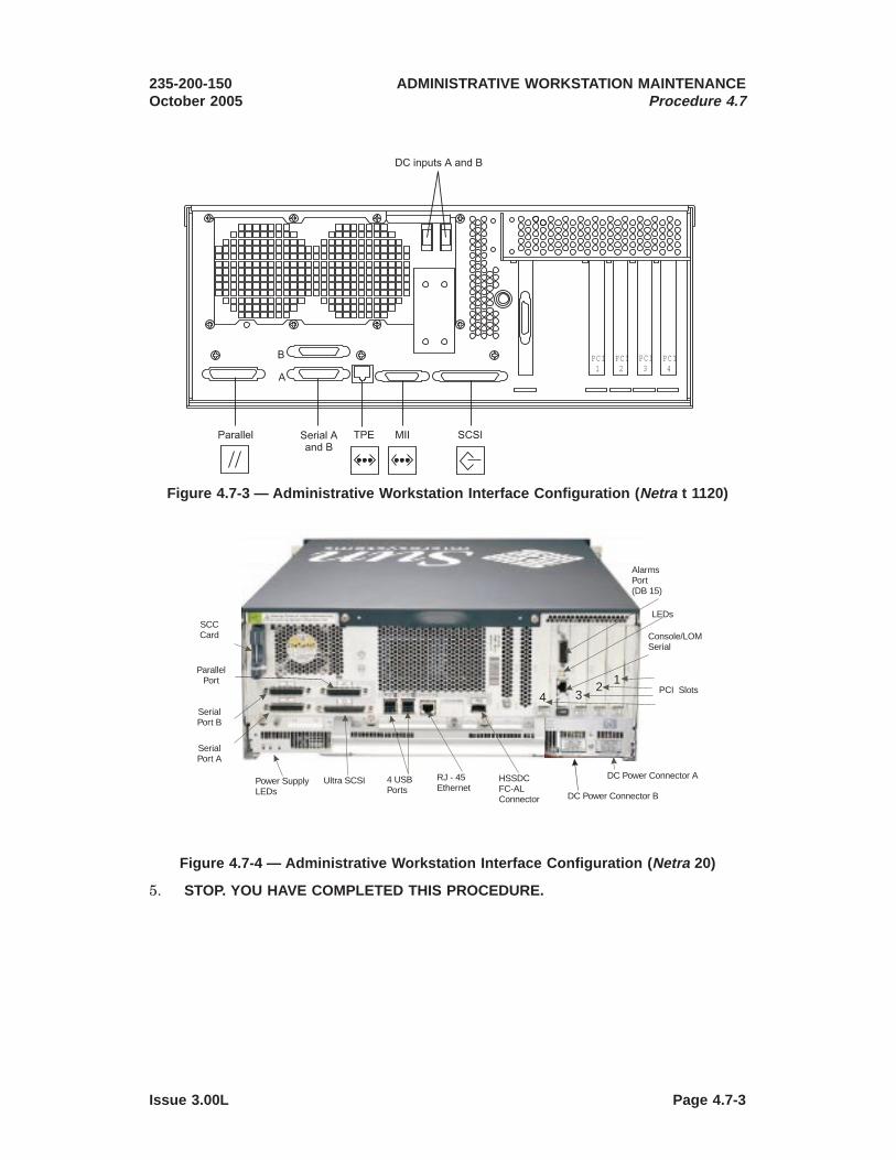
5. STOP. YOU HAVE COMPLETED THIS PROCEDURE.
PCI1
PCI2
PCI3
PCI4
Figure 4.7-3 — Administrative Workstation Interface Configuration ( Netra t 1120)
Console/LOMSerial
LEDs
AlarmsPort(DB 15)
PCI Slots
DC Power Connector B
HSSDCFC-ALConnector
RJ - 45Ethernet
4 USBPorts
Ultra SCSIPower SupplyLEDs
SCCCard
SerialPort A
SerialPort B
ParallelPort
DC Power Connector A
42
31
Figure 4.7-4 — Administrative Workstation Interface Configuration ( Netra 20)
235-200-150October 2005
ADMINISTRATIVE WORKSTATION MAINTENANCEProcedure 4.7
Issue 3.00L Page 4.7-3


4.8 Restore Power to Administrative Workstation ( Netra1 t 1120 and Netra 20)
OVERVIEW
Since all peripherals on the Netra t 1120 and Netra 20 are internal, the only powerthat needs to be restored is the System Power.
PROCEDURE
1. Connect the DC power cables A and B to the AW. See Figure 4.8-1 (Netra t 1120)or 4.8-2 (Netra 20).
1. Trademark of Sun Microsystems, Inc.
PCI1
PCI2
PCI3
PCI4
Figure 4.8-1 — Administrative Workstation Interface Configuration ( Netra t 1120)
235-200-150October 2005
ADMINISTRATIVE WORKSTATION MAINTENANCEProcedure 4.8
Issue 3.00L Page 4.8-1

2. Close the circuit breakers for the DC power cables A and B. To close the circuitbreaker, insert the fuse by pushing in the fuse while turning it clockwise. Thefuse-alarm LED above the fuse will no longer be lit when the fuse is properlyseated.
3. Restore power to the AW by pressing the ON/STBY switch on the front of the AWto the ON “ | ” position and holding it until the system starts to power up.
Console/LOMSerial
LEDs
AlarmsPort(DB 15)
PCI Slots
DC Power Connector B
HSSDCFC-ALConnector
RJ - 45Ethernet
4 USBPorts
Ultra SCSIPower SupplyLEDs
SCCCard
SerialPort A
SerialPort B
ParallelPort
DC Power Connector A
42
31
Figure 4.8-2 — Administrative Workstation Interface Configuration ( Netra 20)
Figure 4.8-3 — Netra t 1120 Power Panel
ADMINISTRATIVE WORKSTATION MAINTENANCEProcedure 4.8
235-200-150October 2005
Page 4.8-2 Issue 3.00L
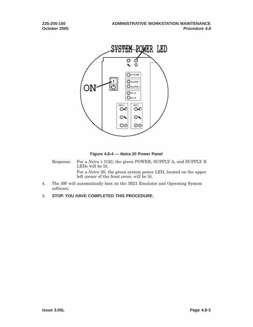
Response: For a Netra t 1120, the green POWER, SUPPLY A, and SUPPLY BLEDs will be lit.For a Netra 20, the green system power LED, located on the upperleft corner of the front cover, will be lit.
4. The AW will automatically boot on the 3B21 Emulator and Operating Systemsoftware.
5. STOP. YOU HAVE COMPLETED THIS PROCEDURE.
Figure 4.8-4 — Netra 20 Power Panel
235-200-150October 2005
ADMINISTRATIVE WORKSTATION MAINTENANCEProcedure 4.8
Issue 3.00L Page 4.8-3


4.9 Remove Power to Administrative Workstation Units ( Netra1 240)
OVERVIEW
This procedure will remove power from the Netra 240 AW and the external DAT tapedrive.
PROCEDURE
1. Be sure the AW has been halted. If this has not already been done, see “Halt theAdministrative Workstation,” Procedure 4.2.
2. Remove power to the DAT tape drive unit. See "Remove Power to DAT TapeDrive Unit (Netra 240)", Procedure 4.15.
3. Remove power to the AW by pressing the ON/STBY switch “ ” on the front ofthe AW and holding it until the system powers down. The green system powerLED, located on the upper left corner of the front cover, will no longer be lit.
4. Open the circuit breaker for the DC power cables A and B connected to the rearof the AW. See Figure 2-7. To open the circuit breaker, push the fuse in whileturning it counter clockwise, and pull the fuse out. The fuse-alarm LED abovethe fuse will be lit once the fuse is no longer seated.
5. Detach the DC power cables A and B from the rear of the AW. See Figure 2-7.
6. STOP. YOU HAVE COMPLETED THIS PROCEDURE.
1. Registered trademark of Sun Microsystems, Inc.
235-200-150March 2006
ADMINISTRATIVE WORKSTATION MAINTENANCEProcedure 4.9
Issue 3.00M Page 4.9-1


4.10 Restore Power to Administrative Workstation Units ( Netra1 240)
OVERVIEW
This procedure will restore power to the Netra 240 AW and the external DAT tapedrive.
PROCEDURE
1. Restore power to the DAT tape drive unit. See "Restore Power to DAT Tape DriveUnit (Netra 240)", Procedure 4.16.
2. Connect the DC power cables A and B to the AW. See Figure 2-7.
3. Close the circuit breakers for the DC power cables A and B. To close the circuitbreaker, insert the fuse by pushing in the fuse while turning it clockwise. Thefuse-alarm LED above the fuse will no longer be lit when the fuse is properlyseated.
4. Restore power to the replacement AW by pressing the ON/STBY switch “ ” onthe front of the AW and holding it until the system starts to power up. The greensystem power LED, located on the upper left corner of the front cover, will be lit.
5. The AW will automatically boot on the 3B21 Emulator and Operating Systemsoftware.
6. STOP. YOU HAVE COMPLETED THIS PROCEDURE.
1. Registered trademark of Sun Microsystems, Inc.
235-200-150October 2005
ADMINISTRATIVE WORKSTATION MAINTENANCEProcedure 4.10
Issue 3.00L Page 4.10-1


4.11 Replace a DAT or CD-ROM/DVD Drive ( Netra1 t 1120)
OVERVIEW
The DAT tape drive and the CD-ROM/DVD drive are built into the AW. Therefore, theAW must be halted before any maintenance on these drives can be performed.
Caution: Follow proper ESD grounding procedures when handling AW units.Wear an antistatic wrist strap and store ESD-sensitive components inantistatic containers.
PROCEDURE
1. Remove power to the AW. See "Remove Power to Administrative Workstation(Netra t 1120 and Netra 20)," Procedure 4.7.
2. Open the top cover of the AW.
Note: If the top cover is not accessible when mounted, the unit may need to becompletely removed from the frame. See “Replace System Unit (Netra t 1120 orNetra 20)”, Procedure 4.6.
a. Remove the two screws from the front of the top cover. See Figure 4.11-1.
b. Pull the top cover tab from the back of the system and lift the cover off.
3. Open the front access cover by twisting the two locking rings counter clockwise tothe open position and lowering the front cover.
1. Trademark of Sun Microsystems, Inc.
Screws
Tabs
Figure 4.11-1 — Removal of the Netra t 1120 Top Cover
235-200-150October 2005
ADMINISTRATIVE WORKSTATION MAINTENANCEProcedure 4.11
Issue 3.00L Page 4.11-1

4. Remove the front ESD plate (see Figure 4.11-2). Use a No.1 Phillips-headscrewdriver to undo the two or three captive screws.
5. Loosen the four captive screws on top of the DAT or CD-ROM/DVD drive thatwill be replaced. If a CD-ROM/DVD drive is being replaced, partially slide thedrive out from the chassis to allow access to the SCSI bus and power connectors.
6. Disconnect the SCSI bus and power connectors from the rear of the DAT orCD-ROM/DVD drive.
7. Pull the DAT or CD-ROM/DVD drive out from the front of the AW chassis.
8. Make sure that all jumper connectors on the set of pins located near the SCSIbus and power connectors at the rear of the replacement DAT or CD-ROM/DVDdrive match the jumper connectors on the rear of the drive being replaced.
Note: The SCSI ID is set using jumper connectors on the set of pins at the rearof the drive. The jumper connectors must be configured so that the SCSI ID forthe DAT drive is set to 4 and the SCSI ID of the CD-ROM/DVD drive is set to 5.
9. Insert the replacement DAT or CD-ROM/DVD drive into the AW chassis so thatthe eject button is at the top right hand side of the faceplate.
10. Connect the SCSI and power cables to the rear of the replacement DAT orCD-ROM/DVD drive.
11. Tighten the four captive screws securing the replacement DAT or CD-ROM/DVDdrive to the drive assembly.
12. Replace the front ESD plate using a No.1 Phillips-head screwdriver to tightenthe three captive screws holding the ESD plate.
Captive Screws
CD-ROM
DAT DRIVE
Figure 4.11-2 — Removal of the Netra t 1120 CDROM/DVD and DAT Drive
ADMINISTRATIVE WORKSTATION MAINTENANCEProcedure 4.11
235-200-150October 2005
Page 4.11-2 Issue 3.00L

13. Replace the front access cover by lifting into place against the AW chassis andtwisting the two locking rings clockwise to the lock position.
14. Replace the top cover of the AW.
a. Position the cover over the system with the screw holes at the front and theslots on each side lined up with the lugs on the sides of the AW.
b. Push the cover forwards until the lugs on the sides are locked in the slots.
c. Replace the screws on the front of the cover.
Note: If the AW was removed from the frame Step 3, install the AW into theframe. See "Replace System Unit (Netra t 1120 or Netra 20)”, Procedure 4.6.
15. Restore power to the AW. See "Restore Power to Administrative Workstation(Netra t 1120 or Netra 20)”, Procedure 4.8.
16. STOP. YOU HAVE COMPLETED THIS PROCEDURE.
235-200-150October 2005
ADMINISTRATIVE WORKSTATION MAINTENANCEProcedure 4.11
Issue 3.00L Page 4.11-3


4.12 Replace a DAT or DVD Drive ( Netra1 TM 20)
OVERVIEW
The DAT tape drive and the DVD drive are built into the AW. Therefore, the AW mustbe halted before any maintenance on these drives can be performed.
Caution: Follow proper ESD grounding procedures when handling AW units.Wear an antistatic wrist strap and store ESD-sensitive components inantistatic containers.
PROCEDURE
1. Remove power to the AW. See "Remove Power to Administrative Workstation(Netra t 1120 or Netra 20)”, Procedure 4.7.
2. Open the top cover of the AW.
Note: If the top cover is not accessible when mounted, the AW may need to becompletely removed from the frame. See "Replace System Unit (Netra t 1120 orNetra 20)”, Procedure 4.6.
a. Loosen the two captive screws from the rear of the top cover. See Figure4.12-1)
b. Pull the top cover tab from the back of the system to disengage the lugs andlift it off.
1. Trademark of Sun Microsystems, Inc.
Figure 4.12-1 — Removal of Netra 20 Top Cover
235-200-150March 2006
ADMINISTRATIVE WORKSTATION MAINTENANCEProcedure 4.12
Issue 3.00M Page 4.12-1

3. Open the front access cover by pulling the cover away from the top of the AWchassis using the finger hold in the center of the cover.
4. Loosen the two captive screws on top of the DAT or DVD drive that will bereplaced. See Figure 4.12-2.
5. Disconnect the SCSI and power connectors from the rear of the DAT or DVDdrive.
6. Pull the DAT or DVD drive out from the front of the AW chassis.
7. Make sure that all jumper connectors on the set of pins located near the SCSIbus and power connectors at the rear of the replacement DAT or CD-ROM/DVDdrive match the jumper connectors on the rear of the drive being replaced.
Note: The SCSI ID is set using jumper connectors on the set of pins at the rearof the drive. The jumper connectors must be configured so that the SCSI ID forthe DAT drive is set to 5 and the SCSI ID of the CD-ROM/DVD drive is set to 6.
8. Insert the replacement DAT or DVD drive into the AW chassis so that the ejectbutton is at the bottom left hand side of the faceplate.
9. Connect the SCSI and power cables to the rear of the replacement DAT or DVDdrive.
10. Tighten the two captive screws securing the replacement DAT or DVD drive tothe drive assembly.
11. Replace the front access cover by pressing the cover into place on the AW chassis.
Figure 4.12-2 — Removal of Netra 20 DAT or DVD
ADMINISTRATIVE WORKSTATION MAINTENANCEProcedure 4.12
235-200-150March 2006
Page 4.12-2 Issue 3.00M
12. Replace the top cover of the AW.
a. Position the cover over the system with the captive screws at the rear andthe lugs on each side lined up with the slots on the sides of the AW.
b. Push the cover forwards until the lugs on the sides are locked in the slots.
c. Tighten the screws on the rear of the cover.
Note: If the AW was removed from the frame in Step 2, install the AW into theframe. See "Replace System Unit (Netra t 1120 or Netra 20)”, Procedure 4.6.
13. Restore power to the AW. See "Restore Power to Administrative Workstation(Netra t 1120 or Netra 20)”, Procedure 4.8.
14. STOP. YOU HAVE COMPLETED THIS PROCEDURE.
235-200-150March 2006
ADMINISTRATIVE WORKSTATION MAINTENANCEProcedure 4.12
Issue 3.00M Page 4.12-3


4.13 Replace System Unit ( Netra1 240)
OVERVIEW
This procedure is used to replace the Netra 240 Administrative Workstation (AW).Before replacing the AW, preliminary checks should be performed to ensure that thecause of failure has not resulted from power becoming unavailable to the unit, thepower switch inadvertently placed to the off position, or the failure of a peripheral(Ethernet2, Serial Asynchronous, or High Speed) interface cable.
Note: This procedure assumes action has been taken to verify the failure is notcaused by a failure of one or both disk drives in the AW. To replace a defective disk,see “Replace a Defective Primary Disk (Netra 240)”, Subprocedure 4.5.4 or “Replace aDefective Secondary Disk (Netra 240)”, Subprocedure 4.5.5.
Caution: Follow proper ESD grounding procedures when handling AW units.Wear an antistatic wrist strap. Handle disk drives by their sides and storeESD-sensitive components in antistatic containers.
PROCEDURE
1. If the AW is operational, continue to Step 2. Otherwise skip to Step 5.
2. Backup the AW operating system to disk and tape (see Backup AdministrativeWorkstation Operating System,” Procedure 4.4).
3. Make full office backup tapes (see 235-105-210, 5ESS®-2000 Switch RoutineOperations and Maintenance ProceduresSection 6.23 “Make Full Office BackupTape”).
4. Halt the AW (see “Halt the Administrative Workstation,” Procedure 4.2).
5. Remove power to the AW (see “Remove Power to Administrative WorkstationUnits (Netra 240),” Procedure 4.9).
6. Remove and label the cables connected to the rear of the AW.
• Serial Port DB-9 Cable
• DAT72 SCSI Bus Cable
• High Speed Interface PCI Card Cable
• SCI PCI Cables
• Ethernet Interface cables.
• DC Power Input Cables to the Power Supply Units
7. Remove the mounting screws securing the AW to the frame. Save the screws formounting the replacement AW to the frame.
8. Remove the AW from the frame by sliding the system forward.
9. Remove the mounting brackets from the AW. Save the screws and brackets formounting the replacement AW to the frame.
10. Remove the disk drives from the AW that will be replaced.
1. Registered trademark of Sun Microsystems, Inc.2. Registered trademark of Xerox, Corp.
235-200-150October 2005
ADMINISTRATIVE WORKSTATION MAINTENANCEProcedure 4.13
Issue 3.00B Page 4.13-1

(a) Grip the bezel at the two finger holds and rotate it down to open (see Figure“Netra 240 Front Fingerholds”, 4.13-1).
(b) Slide the catch at the front of the disk drive to the right (see Figure “Netra240 Disk Drive”, 4.13-2).
(c) Pull the handle and remove the disk drive from AW by sliding it out from itsbay.
Figure 4.13-1 — NETRA 240 Front Fingerholds
ADMINISTRATIVE WORKSTATION MAINTENANCEProcedure 4.13
235-200-150October 2005
Page 4.13-2 Issue 3.00B

11. Repeat Step 10 to remove the disk drives from the replacement AW. Label thesedrives as “Spare Disk”.
12. Install the disk drives, removed from the AW being replaced, into thereplacement AW.
(a) Slide the catch on the front of the disk drive to the right (see Figure “Netra240 Disk Drive”, 4.13-2).
(b) Slide the disk drive into its bay at the front of the server.
(c) Push the metal lever until the drive clicks into place.
(d) Close the bezel until it is locked in place.
13. Install the mounting brackets that were removed in Step 9 onto the replacementAW.
14. Slide the AW into the mounting brackets on the frame.
15. Secure the AW to the frame using the mounting screws that were removed inStep 7.
Figure 4.13-2 — NETRA 240 Disk Drive
235-200-150October 2005
ADMINISTRATIVE WORKSTATION MAINTENANCEProcedure 4.13
Issue 3.00B Page 4.13-3

16. Connect the cables that were removed in Step 6 to the rear of the replacementAW.
17. Restore power to the AW (see “Restore Power to Administrative WorkstationUnits (Netra 240),” Procedure 4.10).
18. STOP. YOU HAVE COMPLETED THIS PROCEDURE.
ADMINISTRATIVE WORKSTATION MAINTENANCEProcedure 4.13
235-200-150October 2005
Page 4.13-4 Issue 3.00B

4.14 Replace a DAT Tape Drive Unit ( Netra1 240)
OVERVIEW
This procedure is used to replace a defective external DAT tape drive unit connectedto the Netra 240 AW.
Before replacing the defective DAT tape drive unit, preliminary checks should beperformed to ensure that the cause of failure has not resulted from loss of power tothe unit or the failure of the SCSI cable connecting the unit to the AW.
Caution: When performing maintenance on the DAT tape drive unit,personnel should be properly grounded, wearing a wrist strap connected to aframe ground or a designated ground connection point.
PROCEDURE
1. Halt the AW (see "Halt the Administrative Workstation," Procedure 4.2).
2. Remove power to the DAT tape drive unit (see "Remove Power to DAT TapeDrive Unit (Netra 240)", Procedure 4.15 ).
3. Disconnect the SCSI cable from SCSI port A at the rear of the DAT tape driveunit. See Figure 4.14-1 (Netra 240 DAT Rear Panel).
4. Remove the mounting screws securing the DAT tape drive unit to the mountingbracket. See Figure 4.14-2 (Netra 240 DAT Front Panel). Save the screws formounting the replacement DAT tape drive unit to the mounting bracket.
1. Registered trademark of Sun Microsystems, Inc.
Figure 4.14-1 — NETRA 240 DAT Rear Panel
235-200-150March 2006
ADMINISTRATIVE WORKSTATION MAINTENANCEProcedure 4.14
Issue 3.00C Page 4.14-1

5. Remove the DAT tape drive unit from the bracket attached to the frame bysliding the unit forward.
6. Slide the replacement DAT tape drive unit onto the mounting bracket attached tothe frame.
7. Secure the replacement DAT tape drive unit to the mounting bracket using themounting screws that were removed in Step 4. See Figure 4.14-2 (Netra 240 DATFront Panel).
8. Reconnect the SCSI cable to SCSI port A at the rear of the replacement DAT tapedrive unit. See Figure 4.14-1 (Netra 240 DAT Rear Panel).
9. Restore power to the DAT tape drive unit (see "Restore Power to DAT Tape DriveUnit (Netra 240)", Procedure 4.16).
10. Restore the AW (see Restore Administrative Workstation", Procedure 4.3).
Result:
The AW will automatically boot on the 3B21 Emulator and Operating Systemsoftware.
Figure 4.14-2 — NETRA 240 DAT Front Panel
ADMINISTRATIVE WORKSTATION MAINTENANCEProcedure 4.14
235-200-150March 2006
Page 4.14-2 Issue 3.00C

11. STOP. YOU HAVE COMPLETED THIS PROCEDURE.
235-200-150March 2006
ADMINISTRATIVE WORKSTATION MAINTENANCEProcedure 4.14
Issue 3.00C Page 4.14-3


4.15 Remove Power to DAT Tape Drive Unit ( Netra1 240)
OVERVIEW
This procedure is used to remove power to the external DAT tape drive unit connectedto the Netra 240 AW.
Caution: When performing maintenance on the DAT tape drive unit,personnel should be properly grounded, wearing a wrist strap connected to aframe ground or a designated ground connection point.
PROCEDURE
1. Remove power to the DAT tape drive unit by opening the circuit breaker for theDC power cable connected to the rear of the unit. To open the circuit breaker,push the fuse in while turning it counter clockwise, and pull the fuse out. Thefuse-alarm LED above the fuse will be lit once the fuse is no longer seated.
2. Use a Philips screwdriver to remove the DC power cable connected to the rear ofthe DAT tape drive unit. The DC power cable is connected to the rear of the unitat a terminal block (positive ’+’ and negative ’-’) and adjacent grounding lug. SeeFigures 4.15-1 (DAT Rear Panel) and 4.15-2 (Netra 240 DAT DC PowerConnections).
1. Registered trademark of Sun Microsystems, Inc.
Figure 4.15-1 — NETRA 240 DAT Rear Panel
235-200-150March 2006
ADMINISTRATIVE WORKSTATION MAINTENANCEProcedure 4.15
Issue 3.00C Page 4.15-1

(a) Start by removing the power cable from the terminal block (positive ’+’ andnegative ’-’).
(b) After the power cabling has been removed from the terminal block, removethe ground wire from the grounding lug.
3. STOP. YOU HAVE COMPLETED THIS PROCEDURE.
Figure 4.15-2 — NETRA 240 DAT DC Power Connections
ADMINISTRATIVE WORKSTATION MAINTENANCEProcedure 4.15
235-200-150March 2006
Page 4.15-2 Issue 3.00C

4.16 Restore Power to DAT Tape Drive Unit ( Netra1 240)
OVERVIEW
This procedure is used to restore power to the external DAT tape drive unit connectedto the Netra 240 AW.
Caution: When performing maintenance on the DAT tape drive unit,personnel should be properly grounded, wearing a wrist strap connected to aframe ground or a designated ground connection point. Also, make sure thatthe circuit breaker for the DC power cable is open before starting thisprocedure.
PROCEDURE
1. Use a Philips screwdriver to connect the DC power cable to the terminal block(positive ’+’ and negative ’-’) and adjacent grounding lug at the rear of the DATtape drive unit. See Figures 4.16-1 (DAT Rear Panel) and 4.16-2 (DAT DC PowerConnections).
1. Registered trademark of Sun Microsystems, Inc.
Figure 4.16-1 — NETRA 240 DAT Rear Panel
235-200-150October 2005
ADMINISTRATIVE WORKSTATION MAINTENANCEProcedure 4.16
Issue 3.00B Page 4.16-1

(a) Start by connecting the ground wire to the grounding lug.
(b) After the ground wire has been connected to the grounding lug, connect thepower cable to the terminal block (positive ’+’ and negative ’-’).
2. Restore power to the DAT tape drive unit by closing the circuit breaker for theDC power cable. To close the circuit breaker, insert the fuse by pushing in thefuse while turning it clockwise. The fuse-alarm LED above the fuse will no longerbe lit when the fuse is properly seated.
3. STOP. YOU HAVE COMPLETED THIS PROCEDURE.
Figure 4.16-2 — NETRA 240 DAT DC Power Connections
ADMINISTRATIVE WORKSTATION MAINTENANCEProcedure 4.16
235-200-150October 2005
Page 4.16-2 Issue 3.00B

4.17 Replace a DVD Drive ( Netra1 240)
OVERVIEW
This procedure is used to replace the DVD drive on a Netra 240 AdministrativeWorkstation. The DVD drive in the Netra 240 is not hot-swappable. The AW must bepowered down and the power input cables disconnected before replacing the DVDdrive.
Caution: The DVD drive contains a laser device. If the replacementprocedures are not followed, the user risks being exposed to radiation.
PROCEDURE
1. Halt the AW (see "Halt the Administrative Workstation," Procedure 4.2).
2. Remove power to the AW (see “Remove Power to Administrative WorkstationUnits (Netra 240)”, Procedure 4.9).
3. Grip the bezel at the two finger holds and rotate it down to open (see Figure4.17-1).
4. Unclip the catches that fasten the DVD drive to the chassis (see Figure 4.17-2).
1. Registered trademark of Sun Microsystems, Inc.
Figure 4.17-1 — NETRA 240 Front Fingerholds
235-200-150October 2005
ADMINISTRATIVE WORKSTATION MAINTENANCEProcedure 4.17
Issue 8.00O Page 4.17-1

5. Pull the DVD drive toward you until it is free of its connectors and out of theserver.
6. Push the replacement DVD drive firmly into the drive slot until the DVDconnector is inserted into the system and the clips engage with the chassis (seeFigure 4.17-2).
7. Close the bezel until it is locked in place.
8. Restore power to the AW (see “Restore Power to Administrative WorkstationUnits (Netra 240)”, Procedure 4.10).
9. STOP. YOU HAVE COMPLETED THIS PROCEDURE.
Figure 4.17-2 — NETRA 240 Front Fingerholds
ADMINISTRATIVE WORKSTATION MAINTENANCEProcedure 4.17
235-200-150October 2005
Page 4.17-2 Issue 8.00O

4.18 Replace a Power Supply Unit ( Netra1 240)
OVERVIEW
This procedure is used to replace a faulty power supply unit in a Netra 240Administrative Workstation (AW). The Netra 240 AW has dual redundant powersupply units. One power supply can be hot-swapped while the other is still running,without having to power off the AW.
Warning: Hands and fingers can be pinched while opening and closing thelevers on the power supply unit. Keep hands and fingers away from the baseand sides of the levers.
PROCEDURE
1. Locate the faulty power supply unit at the rear of the AW. The power supplyunits are labeled on the top cover of the AW as PS 0 and PS 1.
2. Disconnect the power input cable from the power supply unit being replaced.
Caution: Do not remove the power input cable from the remaining powersupply unit. Doing so causes the system to go through an immediateungraceful shutdown.
3. Pull the lever on the back of the power supply unit down (FIGURE 4.18-1). Thisdisconnects the power supply unit from the power distribution board inside theAW.
1. Registered trademark of Sun Microsystems, Inc.
235-200-150October 2005
ADMINISTRATIVE WORKSTATION MAINTENANCEProcedure 4.18
Issue 8.00O Page 4.18-1

4. Slide the power supply unit out of the AW power supply unit bay by pulling onthe lever.
5. Insert the replacement power supply unit in the AW power supply unit bay.
6. Slide the power supply unit into the AW until you feel it engages with the powerdistribution board inside.
7. Ensure that the lever does not return to a vertical position until the powersupply unit engages with the power distribution board. If the lever is vertical, thepower supply unit does not engage correctly.
8. Press the lever up until it clicks. Returning the lever to a vertical positionengages the power supply unit with the power distribution board inside the AW.
9. Connect the power input cable to the power supply unit.
10. The green LED indicator on the back of the power supply unit should light up,indicating that the power supply unit is functioning properly. If the green LEDon the back of the power supply unit does not light up, seek technical assistance.
11. STOP. YOU HAVE COMPLETED THIS PROCEDURE.
Figure 4.18-1 — Netra 240 Power Supply
ADMINISTRATIVE WORKSTATION MAINTENANCEProcedure 4.18
235-200-150October 2005
Page 4.18-2 Issue 8.00O

4.19 Load Tape in DAT Tape Drive Unit
OVERVIEW
This procedure contains steps to insert a 4mm tape cartridge into the DAT tape driveunit.
Note: A Netra1 20 DDS-4 DAT drive can read 90 meter DDS-1 formatted tapes butcan not write 90 meter DSS-1 formatted tapes. A Netra 240 DAT72 drive cannot reador write 90 meter DDS-1 and 120 meter DDS-2 formatted tapes.
PROCEDURE
1. Verify that the tape cartridge’s write-protect switch is set correctly.
For write-protection, the light-colored tab should NOT be visible. Forwrite-enable, the tab should be visible.
2. Check the LEDs on the tape drive front panel to make sure the drive isn’tfunctioning at present.
Both the green and amber LEDs should not be illuminated. It is notrecommended to interrupt the tape drive if the green LED is blinking. A steadygreen LED indicates a data cartridge is in the drive and the drive is ready foractivity. There is a problem if the amber LED is blinking.
3. Netra t 1120 — Insert the tape cartridge so the manufacturer’s label is facing leftand the write enable switch on the cartridge is facing toward you.
Note: On the Netra t 1120 workstation, to access the tape drive, you must firstopen the front cover.
Netra 20 — Insert the tape cartridge so the manufacturer’s label is facing rightand the write enable switch on the cartridge is facing toward you.
Netra 240 — Insert the tape cartridge so the manufacturer’s label is facing upand the write enable switch on the cartridge is facing toward you.
4. Gently push the tape cartridge into the tape drive until the end with thewrite-enable switch is flush with the tape drive front panel. The tape drive isauto-loading and will pull the tape cartridge the remainder of the way into thedrive. DO NOT force the cartridge into the drive. The green LED will blink for afew seconds while the tape is loading then remain steady once the loadingprocess is complete.
5. STOP. YOU HAVE COMPLETED THIS PROCEDURE.
1. Trademark of Sun Microsystems, Inc.
235-200-150October 2005
ADMINISTRATIVE WORKSTATION MAINTENANCEProcedure 4.19
Issue 3.00L Page 4.19-1


4.20 Unload Tape from DAT Tape Drive Unit
OVERVIEW
This procedure contains steps to unload a tape cartridge from the DAT tape drive unit.
PROCEDURE
1. Check the LEDs on the tape drive front panel to make sure you do not abort atape drive activity.
Caution: Do not press the unload button while the drive is in motion asthis will interrupt the drive’s ability to accurately store the data. Waituntil the green LED is on and not blinking before pressing the unloadbutton.
2. If green LED is blinking, wait for tape to stop.
3. Press the UNLOAD button on the front panel of the tape drive and hold it downfor at least one full second, or until the green LED starts flashing.
4. Within 90 seconds, the drive rewinds the tape, ejects the cartridge and the greenLED will stop flashing and remain off. If the cartridge does not eject after 90seconds, execute the Emergency Tape Ejection procedure. See “Emergency TapeEjection (Netra1 t 1120, Netra 20, Netra 240)”, Procedure 4.21.
5. STOP. YOU HAVE COMPLETED THIS PROCEDURE.
1. Registered trademark of Sun Microsystems, Inc.
235-200-150October 2005
ADMINISTRATIVE WORKSTATION MAINTENANCEProcedure 4.20
Issue 3.00L Page 4.20-1


4.21 Emergency Tape Ejection ( Netra1 t 1120, Netra 20 and Netra 240)
OVERVIEW
The operating system can apply a prevent media removal condition to the tape drive.If this condition is active and the system fails, perform this procedure to remove theDAT tape drive unit and reset the prevent media removal condition.
PROCEDURE
1. Halt the system. See “Halt the Administrative Workstation,” Procedure 4.2
2. Remove power to the system or DAT tape drive.
For a Netra t 1120 or Netra 20 AW, see "Remove Power to AdministrativeWorkstation (Netra t 1120 and Netra 20), Procedure 4.7.
For a Netra 240 AW, see "Remove Power to DAT Tape Drive Unit (Netra 240)",Procedure 4.15.
3. Restore power to the system or DAT tape drive.
For a Netra t 1120 or Netra 20 AW, see "Restore Power to AdministrativeWorkstation (Netra t 1120 and Netra 20), Procedure 4.8.
For a Netra 240 AW, see "Restore Power to DAT Tape Drive Unit (Netra 240)",Procedure 4.16.
4. Press the UNLOAD button.
5. For a Netra t 1120 or Netra 20 AW, verify that the emulated AM environment isrestored automatically.
6. STOP. YOU HAVE COMPLETED THIS PROCEDURE.
1. Trademark of Sun Microsystems, Inc.
235-200-150October 2005
ADMINISTRATIVE WORKSTATION MAINTENANCEProcedure 4.21
Issue 3.00L Page 4.21-1


4.22 Clean the DAT Tape Drive Unit Head
OVERVIEW
The tape drive head must be cleaned regularly to maintain its reliable operation.Clean the tape drive after every 25 hours of actual tape operation and only with aDDS cleaning cartridge. These cleaning cartridges have the same shape and size asregular media cartridges. No fluids or other preparations are necessary with the use ofthese cartridges.
Failure to regularly clean the tape drive may result in an accumulation of debris thatcannot be removed with the cleaning cartridge. This could result in unreliableread/write operations on the drive.
PROCEDURE
1. Insert the cartridge into the DAT tape drive unit as you would a data tapecartridge.
2. Observe the green LED blinking slowly to indicate that the tape drive isautomatically performing the cleaning cycle.
If the cartridge has been used for more than 30 cleaning cycles (depending on thebrand), the amber LED will blink rapidly. Press the UNLOAD button to eject thecartridge and discard it.
Note: If the amber LED is flashing at a rate of approximately four flashes persecond during the cleaning operation, it indicates the cleaning tape is worn.
3. Remove the cleaning cartridge after it is automatically ejected following thecleaning cycle. The tape drive is immediately available for use.
Caution: Do not use cleaning cartridges or types of fluids designed foruse in audio devices as these can damage the tape drive.
4. STOP. YOU HAVE COMPLETED THIS PROCEDURE.
235-200-150January 2003
ADMINISTRATIVE WORKSTATION MAINTENANCEProcedure 4.22
Issue 3.00 Page 4.22-1


Distinctive Remote Module (DRM)
CONTENTS PAGE
5. ROUTINE MAINTENANCE . . . . . . . . . . . . . . . . . . . 5-1
5.1 Load Software Update(s) from SCANS . . . . . . . . . . . 5.1-1
5.2 Load Software Update(s) from Tape . . . . . . . . . . . . 5.2-1
5.3 Load Software Update(s) from ASM . . . . . . . . . . . . 5.3-1
5.4 Make Software Update(s) Official . . . . . . . . . . . . . 5.4-1
5.5 Install Operating System Software Update . . . . . . . . . . 5.5-1
5.6 Backout Last Official Software Update(s) . . . . . . . . . . 5.6-1
5.7 Backout Software Update . . . . . . . . . . . . . . . . 5.7-1
5.8 Backout Operating System Software Update . . . . . . . . . 5.8-1
5.9 Compact Switch Processor Patch Space . . . . . . . . . . 5.9-1
5.10 Activate/Deactivate Balance Feature . . . . . . . . . . . . 5.10-1
5.10.1 Populate Low Level ECD Forms for Log FileRetrieval . . . . . . . . . . . . . . . . . . . . 5.10.1-1
5.10.2 Populate Low Level ECD Forms for TTY Port . . . . . . 5.10.2-1
5.10.3 Backup Incore ECD to Disk . . . . . . . . . . . . . 5.10.3-1
5.10.4 Activate Balance Feature . . . . . . . . . . . . . . 5.10.4-1
5.10.5 Deactivate Balance Feature . . . . . . . . . . . . . 5.10.5-1
5.10.6 Backup Office Dependent Data . . . . . . . . . . . 5.10.6-1
5.11 Integrate Vendor Stratum 3 Bits Timing Source . . . . . . . . 5.11-1
LIST OF FIGURES
Figure 5.11-1 — BITS BOX Cabling . . . . . . . . . . . . . . . . . 5.11-3
Figure 5.11-2 — Telecom Solutions BITS BOX Cabling Connection . . . . 5.11-4
Figure 5.11-3 — TSICOM Cabling Connection . . . . . . . . . . . . . 5.11-5
235-200-150June 2004
ROUTINE MAINTENANCE
Issue 3.00J Page 5-i
5 . 1 1 - 5
5 . 1 1 - 4
5 . 1 1 - 3
5 . 1 1 - 1
5.10-1
5.9-1
5.8-1
5.7-1
5.6-1
5.5-1
5.4-1
5.3-1
5.2-1
5.1-1
5 - 1

LIST OF TABLES
Table 5.10-1 — Activate/Deactivate Balance Feature Activity Selection . . . 5.10-1
ROUTINE MAINTENANCE 235-200-150June 2004
Page 5-ii Issue 3.00J
5.10-1

5. ROUTINE MAINTENANCE
Overview
Note: Although procedure steps involving software commands can be performed viathe ASM (via an OA&M cut-through), someone must be present at the DRM office toperform any hardware portions.
Routine maintenance consists of activities that are performed to maintain a highdegree of switch performance. Preventative maintenance is performed on a specifiedschedule to ensure continuing peak overall performance of the network.
Since peak load periods, features, recent change activities, growth, etc., vary widely indifferent offices, some tests, such as Routine Exercise (REX), may not have specifictest schedules that are best for all offices. In cases of this type, the Equipment TestList (ETL) gives references where procedures, recommendations, and/or guidelines canbe found for the listed test(s).
For more information on software updates, backup procedures, and the ETL, see235-105-210, 5ESS® Switch Routine Operations and Maintenance Procedures.
Note: Tape backup of the entire office should be done at least once a month or moreoften if many software updates are being added to the office. See Make Full OfficeBackup Tape, 235-105-210, Routine Operations and Maintenance Procedures.
235-200-150June 2004
ROUTINE MAINTENANCE
Issue 3.00J Page 5-1

5.1 Load Software Update(s) from SCANS
OVERVIEW
Note: It is recommended that the host 5E and all subtending DRMs be maintainedat the same or within 1 SU/BWM level of each other, with only 2 SU/BWM levelsacross all nodes. The Host 5E should always be updated first before updating anyDRMs.
If the host and subtending DRMs become more than 1 SU/BWM level apart or at least1 DRM is at a higher SU/BWM level than the host 5E, the following will occur:
1. The application of a new SU/BWM on the 5E will be blocked. If this cannot becorrected by updating the SU level on the DRM(s), the following command canbe entered at a 3B21 unix prompt to override the check that blocks the SUapplication:
touch /etc/.NO2LVLCHECK
2. The following output message may be generated on the ROP when accessingRecent Change & Verify (RCV) for a DRM via the ASM:
*REPT ASM VTTY ASM SERVICE rc NOT AVAILABLE, USING AM SERVICEINSTEAD
This message indicates that layer 1 and 2 RCV crosschecks will be performedlocally on the DRM rather than on the ASM. This will result in a slight decreasein RCV throughput but will not block the ability to perform RCV.
Once an SU has been sent to the /etc/bwm directory using the following procedure,the SU can be applied by using either a cut-through to the Host and each DRM andmanually applying the SU from the 1990 MCC page or by using SU Automation(section 2.12.6.2) to automatically apply the SU to the Host and all DRMs in theSwitching Complex The SU Automation method can only be used when an SU is to beinstalled on the Host and all the DRMs in the complex together. If SU installation ononly the Host or a subset of DRMs is desired, then it must be done via a cut-throughto each Host/DRM’s MCC.
The DRM and host can be in different stages of BWM installation.
Note: This procedure should only be used if dsdownload on the ASM is notavailable! For dsdownload procedure refer to the 235–200–145:5ESS® SwitchOneLink Manager Administrative Services Module User’s Guide, Chapter “HandlingSoftware Updates.”
This procedure can be performed via the ASM or at a DRM site.
In order to load a software update using the Software Change Administration andNotification System (SCANS), a terminal and dial-up modem are needed along with aSCANS login. When the SCANS login is obtained, the SCANS User’s Guide and theTraining Manual are also provided.
SCANS provides menu driven access to informational bulletins and software updates(SUs). The basic process of loading an overwrite from SCANS is as follows:
• Set up the AW to receive an SU from SCANS.
• Log in to the SCANS system and request the software update.
235-200-150Feburary 2007
ROUTINE MAINTENANCEProcedure 5.1
Issue 3.00k Page 5.1-1

• Log out from SCANS and wait for the SCANS system to send the SU(s) over theSCANS data link (connected to port 0 on the High Speed Bus Interface [HSI]).This could take up to 24 hours.
• Monitor the status of the SCANS download.
• Verify download is complete.
• Proceed to the “Make Software Update(s) Official,” Procedure 5.4, to apply theSU. Be sure to review the SU and follow any supplied instructions.
Note: Become completely familiar with the SCANS system prior to running thisprocedure.
There is a 24-hour time limit imposed from the time the switch is primed untilSCANS must begin the data session. If SCANS puts the software update load requestin the queue, it may take up to that 24-hour limit to start sending data to the switch.IN REMOTE STARTED is output to indicate the start of the data session. The INREMOTE REPT message may be output periodically during the session to indicatedownload progress. Termination of the session is indicated by an IN REMOTE REPToutput message followed immediately by the IN REMOTE STOPPED output message.
PROCEDURE
1. At the MCC, type and enter:
IN:REMOTE:START;
Purpose
Requests that the Administrative Workstation (AW) be put in theremote-file-receive mode. This message should be entered immediately beforeordering delivery of software update files from the Software ChangeAdministration and Notification System (SCANS-2), so that the transaction IDdisplayed in the IN REMOTE output message can be supplied in the order toSCANS-2. Software updates must begin to arrive at the AdministrativeWorkstation within 24 hours. Responsive messages are printed when they areinitially received or when this time limit is reached.
Response: IN REMOTE INITIALIZEDTRANSACTION ID: a TIME: b
Where: a = transaction ID to be supplied to SCANS. This ID value isrequired in Step 3 .b = time at which 24-hour timer began in the format hours:minutes.
2. At the SCANS terminal, log in to SCANS per local instructions. Your SCANSpassword will be required.
3. Using the SCANS menu-driven system, request a load of the software update(s).Refer to the SCANS User’s Guide and SCANS Training Manual supplied withthe SCANS login for further detail.
4. SCANS will download the requested SU(s) sometime within the next 24 hours.Monitor the progress of the download using IN:REMOTE:REPT; .
The possible responses are:IN REMOTE WAITING
indicates SCANS has yet to download the requested SU(s).
ROUTINE MAINTENANCEProcedure 5.1
235-200-150Feburary 2007
Page 5.1-2 Issue 3.00k

orIN REMOTE IN PROGRESS
FILES RECEIVED: x IN PROGRESSELAPSED TIME xx:xx SPACE REMAINING xxxx IN PROGRESSINODES REMAINING xxxx
indicates the download is in progress.
orIN REMOTE ERROR 12
indicates the download completed either successfully or unsuccessfully.
5. Have the following messages printed on the ROP?IN REMOTE STOPPED xREPT RCVRY SDL 0 COMPLETED
If YES, continue with Step 6. If NO, continue to monitor SCANS using Steps 4and 5.
Note: SCANS will download the software update (SU) within 24 hours. Userscan reenter SCANS to verify downloading has started or to see where the SU isin the queue. If SCANS indicates the SU has been downloaded and the previousmessages have not been printed, continue with Step 6.
6. At the MCC, type and enter:
OP:STATUS:LISTDIR, fn=" /etc/bwm";
total 101 drwxrwxrwx 2 root 48 Jan 21 13:569 drwxr -xr -x 2 root 4176 Jan 26 09:40
Note: The output will contain the contents of the /etc/bwm directory.
7. The SU number requested should appear on this list.
If YES, STOP. YOU HAVE COMPLETED THIS PROCEDURE.
If NO, seek technical assistance .
235-200-150Feburary 2007
ROUTINE MAINTENANCEProcedure 5.1
Issue 3.00k Page 5.1-3


5.2 Load Software Update(s) from Tape
OVERVIEW
Note: It is recommended that the host 5E and all subtending DRMs be maintainedat the same or within 1 SU/BWM level of each other, with only 2 SU/BWM levelsacross all nodes. The Host 5E should always be updated first before updating anyDRMs.
If the host and subtending DRMs become more than 1 SU/BWM level apart or at least1 DRM is at a higher SU/BWM level than the host 5E, the following will occur:
1. The application of a new SU/BWM on the 5E will be blocked. If this cannot becorrected by updating the SU level on the DRM(s), the following command canbe entered at a 3B21 unix prompt to override the check that blocks the SUapplication:
touch /etc/.NO2LVLCHECK
2. The following output message may be generated on the ROP when accessingRecent Change & Verify (RCV) for a DRM via the ASM:
*REPT ASM VTTY ASM SERVICE rc NOT AVAILABLE, USING AM SERVICEINSTEAD
This message indicates that layer 1 and 2 RCV crosschecks will be performedlocally on the DRM rather than on the ASM. This will result in a slight decreasein RCV throughput but will not block the ability to perform RCV.
Once an SU has been sent to the /etc/bwm directory using the following procedure,the SU can be applied by using either a cut-through to the Host and each DRM andmanually applying the SU from the 1990 MCC page or by using SU Automation(section 2.12.6.2) to automatically apply the SU to the Host and all DRMs in theSwitching Complex The SU Automation method can only be used when an SU is to beinstalled on the Host and all the DRMs in the complex together. If SU installation ononly the Host or a subset of DRMs is desired, then it must be done via a cut-throughto each Host/DRM’s MCC.
The DRM and host can be in different stages of BWM installation.
Note: This procedure should only be used if dsdownload is not available.
This procedure can be performed via the ASM or at a DRM site.
PROCEDURE
1. Mount the software update tape on tape drive.
Reference: “Load Tape in DAT Tape Drive,” Procedure 4.19.
2. At the MCC, type and enter:COPY:TAPE:IN,TD="/dev/mt00",BSDIR="/etc/bwm";
Response: COPY TAPE IN COMPLETED
3. Unmount software update tape.
Reference: “Unload Tape from DAT Tape Drive,” Procedure 4.20.
4. STOP. YOU HAVE COMPLETED THIS PROCEDURE.
235-200-150Feburary 2007
ROUTINE MAINTENANCEProcedure 5.2
Issue 3.00I Page 5.2-1


5.3 Load Software Update(s) from ASM
OVERVIEW
Note: It is recommended that the host 5E and all subtending DRMs be maintainedat the same or within 1 SU/BWM level of each other, with only 2 SU/BWM levelsacross all nodes. The Host 5E should always be updated first before updating anyDRMs.
If the host and subtending DRMs become more than 1 SU/BWM level apart or at least1 DRM is at a higher SU/BWM level than the host 5E, the following will occur:
1. The application of a new SU/BWM on the 5E will be blocked. If this cannot becorrected by updating the SU level on the DRM(s), the following command canbe entered at a 3B21 unix prompt to override the check that blocks the SUapplication:
touch /etc/.NO2LVLCHECK
2. The following output message may be generated on the ROP when accessingRecent Change & Verify (RCV) for a DRM via the ASM:
*REPT ASM VTTY ASM SERVICE rc NOT AVAILABLE, USING AM SERVICEINSTEAD
This message indicates that layer 1 and 2 RCV crosschecks will be performedlocally on the DRM rather than on the ASM. This will result in a slight decreasein RCV throughput but will not block the ability to perform RCV.
Once an SU has been sent to the /etc/bwm directory using the following procedure,the SU can be applied by using either a cut-through to the Host and each DRM andmanually applying the SU from the 1990 MCC page or by using SU Automation(section 2.12.6.2) to automatically apply the SU to the Host and all DRMs in theSwitching Complex The SU Automation method can only be used when an SU is to beinstalled on the Host and all the DRMs in the complex together. If SU installation ononly the Host or a subset of DRMs is desired, then it must be done via a cut-throughto each Host/DRM’s MCC.
The DRM and host can be in different stages of BWM installation.
PROCEDURE
1. To load software updates on the DRM via the ASM, follow instructions found in235–200–145, 5ESS® Switch OneLink Manager™Administrative Service ModuleUser’s Guide, ASM Release 5.0 and Earlier section, SU Download Via ASM.
235-200-150Feburary 2007
ROUTINE MAINTENANCEProcedure 5.3
Issue 3.00I Page 5.3-1


5.4 Make Software Update(s) Official
OVERVIEW
This procedure takes the software update(s) previously loaded into the /etc/bwm fromeither SCANS or tape, and verifies the files, then applies the software update in"temporary" mode. Next the update enters into a soak period during which time anyproblems with the update may be discovered. This soak period may last a day or more.Following the soak period, the overwrite is made official and the files are removedfrom /etc/bwm.
With this procedure, a desired point of installation may be entered. Maintenancepersonnel can:
1. Step through each stage of an SU Installation one step at a time, or
2. Install an SU through any stage of the installation (including make-official) withjust one poke. The SU Installation will stop if an error occurs or if the stopinstallation poke is entered.
Following is a list of status indicators that will appear during this procedure:
Status Color Key Wordnot executed yellow —completed green COMPLTDstopped blue (steady) STOPPEDaborted red ABORTEDin progress blue (flashing) INPROGR
PROCEDURE
1. Using the listing of software updates, choose the software update with lowestsequence number.
2. At the MCC Page 1990, type and enter: 9,"yyyyyyyyyy" to start the softwareupdate process.
Where: y. . . y = 6-digit or 10-digit software update number, craft (CFT)software update number, or temporary (TMP) software updatenumber.
This will introduce an SU for installation.
Response: The SU name will appear in the page title.
3. At the MCC Page 1990, type and enter: 1 to verify software update and buildexecutable message file.
Response: The verify stage box will change from yellow to a flashing blue anddisplay the word INPROGR. This will continue until the verifyaborts or completes. If aborted, the indicator box will change to redand display ABORTED. If the verify successfully completes, theindicator box will change to green and display the word COMPLTD.
4. At the MCC Page 1990, type and enter: 11 to print entire message file.
Response: Message file printed at ROP.
Review message file for events that will take place during activation, or anyspecial actions which must be accomplished manually.
235-200-150January 2003
ROUTINE MAINTENANCEProcedure 5.4
Issue 3.00 Page 5.4-1

5. At the MCC Page 1990, type and enter: 2 to start the execution of the PREPAREsection.
Response: The prepare stage box will change from yellow to a flashing blue anddisplay the word INPROGR. This will continue until the prepareaborts, stops or completes. If aborted, the indicator box will changeto red and display ABORTED. If the installation is stoppedsuccessfully, the flashing will stop and the indicator box will displaythe word STOPPED. If, however, the prepare successfully completes,the indicator box will change to green and display the wordCOMPLTD.
6. To back-out, type and enter: 6, otherwise, proceed to the next step.
Response: The back-out indicator will flash blue. Once completed, the back-outindicator will appear green and the prepare stage indicator box willrevert back to yellow (not executed or initial state).
7. Type and enter: 3 to install through activate.
Response: The stage indicator will change as in the prepare case. Once activatecompletes, proceed to the next step.
8. To back-out or deactivate at this point, type and enter: 6 or 7, otherwise, continueto the next step.
Response: The back-out or deactivate indicator will flash blue. Once completed,the corresponding indicator will appear green and the installationstage indicators will revert back to the point indicated by thearrows.
9. At the MCC Page 1990, type and enter: 4 to execute SOAK section of messagefile.
Response: The stage indicators will change as in the prepare case. Once thesoak section completes, and if there is a default soak time, the soaktimer will start. This will cause the page to repaint with the 1991page displayed over the lower portion of the 1990 page. The 1991page will display the SU soaking, the start and end times, and soaktimer options like reset and abort. When the timer completes, the1991 will disappear and the soak stage indicator will change togreen and read COMPLTD.
10. At the MCC Page 1990, type and enter: 5 to start the execution of the OFFICIALsection.
Response: The make official stage indicator box will change from yellow toflashing blue and read INPROGR. Once all the lines in the sectionsuccessfully complete, the indicator will change to green and readCOMPLTD.If during this step the indicator reads: OFFICIAL STOPPED,perform the following substeps:
(a) At the command line, type and enter: OP:INIT:EMULATOR to perform anAdministrative Workstation (AW) initialization.
Warning: The AW initialization process is NOT service-impacting,however, video terminal and data link access will be unavailableand the switching module will be ISOLATED for about 4 to 5minutes.
ROUTINE MAINTENANCEProcedure 5.4
235-200-150January 2003
Page 5.4-2 Issue 3.00

(b) At the MCC Page 1990, type and enter: 5 to re-start the execution of theOFFICIAL section.
(c) At the MCC Page 112, type and enter: 301 and 303 to restore the MHDs.
11. STOP. YOU HAVE COMPLETED THIS PROCEDURE.
235-200-150January 2003
ROUTINE MAINTENANCEProcedure 5.4
Issue 3.00 Page 5.4-3


5.5 Install Operating System Software Update
PROCEDURE
1. Halt the AM emulator (see "Halt the Administrative Module (AM) Emulator,”Procedure 4.1).
2. Switch to the UNIX1 console of the AW by holding down the Ctrl key andpressing Enter (not Return).
3. If a login prompt does not appear, press Return repeatedly until one appears.
4. At the login prompt, login as awadmin , for example:
attaws console login: awadmin
5. From the Administrative Workstation Main Menu, select "Halt the emulator" andread the information.
6. Enter CARRIAGE RETURN to continue.
7. From the Administrative Workstation Main Menu, select "Install OperatingSystem Software Update."
8. From the Operating System Software Update installation menu, select "Executeinstallation of an Operating System Software Update." Answer yes to theconfirmation. If you select a task by mistake, answer no to the confirmation.
Response:You have chosen to install an operating system software update. If theemulator is running, it must be halted before continuing. Refer to themain menu item of Halt the Emulator.
Note: If you continue, expect severall lines of printout, some ofwhich may say: ‘tar: problem reading group entry’. Thisis normal and should be disregarded.
Do you want to continue? (yes/no) yes
9. This task will take approximately 2 minutes. When it is completed, you will beprompted to press Return. When the prompt appears, press Return .
The operating system software update installation has completed. At this timethe workstation must be rebooted.
10. To view the output of this Operating System Software Update, select "Viewoutput from the most recent Operating System Software Update Install." Whileviewing the output, use the following keys:
space see the next screen of outputb see the previous screen of outputh see a list of available keysq quit viewing output
11. Select "Return to the main menu."
1. Registered trademark in the United States and other countries, licensed exclusively through X/OpenCompany, Limited
235-200-150January 2003
ROUTINE MAINTENANCEProcedure 5.5
Issue 3.00 Page 5.5-1

12. From the Administrative Workstation Main Menu, select "Boot the Workstation."Answer yes to the confirmation. If you select a task by mistake, answer no to theconfirmation.
Response:You have chosen to boot the workstation. If the emulator is running,it must be halted before continuing. Refer to the main menu item ofHalt the Emulator.
Do you want to continue? (yes/no) yes
13. The emulated AM environment is restored automatically, verify that this hasoccurred.
14. If the UNIX console page is displayed, switch to the MCC of the AW by holdingdown the Ctrl key and pressing Enter (not Return).
15. STOP. YOU HAVE COMPLETED THIS PROCEDURE.
ROUTINE MAINTENANCEProcedure 5.5
235-200-150January 2003
Page 5.5-2 Issue 3.00

5.6 Backout Last Official Software Update(s)
OVERVIEW
This procedure allows up to three software updates previously made official to bebacked out. If the update files in /etc/bwm were cleared, it will not be possible tore-apply these overwrites without first replacing the files in /etc/bwm from SCANS ortape.
Warning: At any point of this procedure, an Administrative Workstation (AW)initialization may be required. If this is necessary, the AW initializationprocess is NOT service-impacting, however, video terminal and data linkaccess will be unavailable and the switching module will be ISOLATED forabout 4 to 5 minutes.
PROCEDURE
1. At the MCC Page 1950, Program Update Maintenance, type and enter: 9900
2. After the command is entered, you will be asked to confirm your decision bytyping Y/N. IN PROGRESS appears if response is Y.
Response: IN PROGRESS appears next to 9900 command line.
Note: If the software update contains updates with TARGET=EMULATOR,depending on the update package an initialization may be required to deactivatethe update.
3. Access MCC Page 1990
Response: EXECUTE UPD:INIT:EMULATOR TO DEACTIVATE UPDATE
(a) Using the RESPONSE field on MCC Page 1990, is an initialization of theemulator required?
If YES, continue with Step 3b.
If NO, go to Step 4.
(b) Write AMA data to disk. Type and enter:
WRT: AMADATA;
Response: REPT AMA DISK WRITER FOR STREAM ST1RECORDING TO DISK SUSPENDEDREPT AMA DISK WRITER FOR STREAM ST1RECORDING TO DISK RESUMED
(c) Request 3B21 emulator initialization. Type and enter:
UPD:INIT:EMULATOR;
Response: AW completes emulator initialization. MCC displays EAI Pagefollowed the 111 Page.
(d) After initialization completes, return to MCC page 1950.
4. Did command complete successfully and is COMPLETED displayed next to the9900 command?
If YES, continue with the next step.
If NO, repeat Step 2. If command continues to fail, seek technical assistance .
235-200-150November 2003
ROUTINE MAINTENANCEProcedure 5.6
Issue 3.00F Page 5.6-1

(a) If the software update backout included an emulator update (see Step 3a),then perform “Backup Administrative Workstation Operating System,”Procedure 4.4.
5. If the "new" last official software update needs to be backed out, go to Step 2.
Note: No more than three official software updates can be removed this way.
6. STOP. YOU HAVE COMPLETED THIS PROCEDURE.
ROUTINE MAINTENANCEProcedure 5.6
235-200-150November 2003
Page 5.6-2 Issue 3.00F

5.7 Backout Software Update
OVERVIEW
This procedure can be used to backout software updates which are in the temporary orsoaking state.
Warning: During the execution of the Backout Software Update procedure,an Administrative Workstation (AW) initialization may be required. If this isnecessary, the AW initialization process is NOT service-impacting, however,video terminal and data link access will be unavailable and the switchingmodule will be ISOLATED for about 4 to 5 minutes.
Note: To backout the last official software update, refer to “Backout LastOfficial Software Update(s),” Procedure 5.6.
PROCEDURE
1. Access MCC Page 1990, SU INSTALLATION page.
Is software update number displayed to the right of “SU INSTALLATION OF”the software update that needs to be backed out?
If YES, continue with Step 3.
If NO, continue to Step 2.
2. At the MCC Page 1990, in order to start the software update process, type andenter:
9,"yyyyyyyyyy"
Where: y . . . y = 6-digit or 10-digit software update number.
Response: On MCC Page 1990, status of software update is displayed in stagebox and RESPONSE line.
Message file displayed for next section to be executed.
3. At the MCC Page 1990, type and enter: 6 to backout software update.
Response: EXECUTE ALL COMPLETED: BACKOUT SECTION
Note: If the software update contains an update with TARGET=EMULATOR,depending on the update package, an initialization may be required to deactivatethe update.
Response: EXECUTE UPD:INIT:EMULATOR TO DEACTIVATE UPDATE
(a) Using the RESPONSE field of MCC Page 1990, is an initialization of theemulator required?
If YES, continue with Step 3b.
If NO, go to Step 4.
(b) Write AMA data to disk. Type and enter:
WRT: AMADATA;
Response: REPT AMA DISK WRITER FOR STREAM ST1RECORDING TO DISK SUSPENDEDREPT AMA DISK WRITER FOR STREAM ST1RECORDING TO DISK RESUMED
235-200-150November 2003
ROUTINE MAINTENANCEProcedure 5.7
Issue 3.00F Page 5.7-1

(c) Request 3B21 emulator initialization. Type and enter:UPD:INIT:EMULATOR;
Response: AW completes emulator initialization. MCC displays EAI Pagefollowed by the 111 Page.
(d) After initialization completes, return to MCC Page 1990.
Did backout complete successfully and “BACK-OUT SECTIONCOMPLETED” displayed on the RESPONSE line?
If YES, continue with Step 3e.
If NO, Repeat Step 3 from the beginning. If step 3 is repeated and thebackout does not complete successfully, seek technical support .
(e) If the software update backout included an emulator update (see Step 3a),then perform the “Backup Administrative Workstation Operating System,”Procedure 4.4.
4. STOP. YOU HAVE COMPLETED THIS PROCEDURE.
ROUTINE MAINTENANCEProcedure 5.7
235-200-150November 2003
Page 5.7-2 Issue 3.00F

5.8 Backout Operating System Software Update
PROCEDURE
1. Halt the AM emulator (see "Halt the Administrative Module [AM] Emulator,”Procedure 4.1).
2. Switch to the UNIX1 console of the AW by holding down the Ctrl key andpressing Enter (not Return).
3. If a login prompt does not appear, press Return repeatedly until one appears.
4. At the login prompt, login as awadmin , for example:
attaws console login: awadmin
5. From the Administrative Workstation Main Menu, select "Backout OperatingSystem Software Update."
6. From the Operating System Software Update Backout Menu, select "Executebackout of an Operating System Software Update." Answer yes to theconfirmation. If you select a task by mistake, answer no to the confirmation.
Response:You have chosen to backout the most recent operating System SoftwareUpdate. If the emulator is running, it must be halted before continuing.Refer to the main menu item of Halt the Emulator.
Do you want to continue? (yes/no) yes
7. This task will take approximately 2 minutes. When it is completed, you will beprompted to press Return. When the prompt appears, press Return .
The operating system software update backout has completed. At this time theworkstation must be rebooted.
8. To view the output of this backout Operating System Software Update, select"View output from the most recent Operating System Software Update Backout."While viewing the output, use the following keys:
space see the next screen of outputb see the previous screen of outputh see a list of available keysq quit viewing output
9. Select "Return to the main menu."
10. From the Administrative Workstation Main Menu, select "Boot the workstation."Answer yes to the confirmation. If you select a task by mistake, answer no to theconfirmation.
Response:You have chosen to boot the workstation.If the emulator is running,it must be halted before continuing. Refer to the main menu item ofHalt the Emulator.
1. Registered trademark in the United States and other countries, licensed exclusively through X/OpenCompany, Limited
235-200-150January 2003
ROUTINE MAINTENANCEProcedure 5.8
Issue 3.00 Page 5.8-1

Do you want to continue? (yes/no) yes
11. The emulated AM environment is restored automatically, verify that this hasoccurred.
12. If the UNIX console page is displayed, switch to the MCC of the AW by holdingdown the Ctrl key and pressing Enter (not Return).
13. STOP. YOU HAVE COMPLETED THIS PROCEDURE.
ROUTINE MAINTENANCEProcedure 5.8
235-200-150January 2003
Page 5.8-2 Issue 3.00

5.9 Compact Switch Processor Patch Space
OVERVIEW
The patch space compaction is normally used when the target’s switching modulepatch space becomes insufficient and failed the program update process. The patchspace compaction operation will try to increase the size of the target’s patch space andmake the program update process successful.
Note: If there is a need to backout of patch space compaction after it has been madeofficial, the backout last official (BOLO) process can be used for backout. See “BackoutLast Official Software Update(s),” Procedure 5.6.
The target’s patch space may become so fragmented or insufficient that even thisprocedure will be unable to generate sufficient patch space for a successful programupdate process.
PROCEDURE
1. Enter the following command:
UPD:PATCH:TARGET= a,ACTION=b;
Where: a = SM, SM2K, or CMPb = APPLY, OFC, or BKOUT
APPLY = Execute patch space compaction and APPLY on requested target.
OFC = make official for APPLYed target.
BKOUT = Backout previously requested APPLYed target.
The system responds with:
NG = No good.
PF = Printout follows. The ALW:TRFC30 output message will be printed.
INPROG = In progress. The message was accepted and the action is in progress.
CMPL,action = complete action’s process. The valid values for action are: APPLY,OFC or BKOUT.
2. STOP. YOU HAVE COMPLETED THIS PROCEDURE.
235-200-150January 2003
ROUTINE MAINTENANCEProcedure 5.9
Issue 3.00 Page 5.9-1


5.10 Activate/Deactivate Balance Feature
OVERVIEW
This procedure activates the ability to provide data for blocked-call identification onanalog line units (LU1, LU2, and LU3) in a switching module. The data (high CCSusers that cause blocking) is delivered to the Administrative Module (AM) by humanmachine messages. But to collect the data the balance feature must be activated.
The balance data may be directed to either the TTY port or the 3B21 emulator logfiles. Activity in the ECD accomplishes this. It is assumed the TTY port has alreadybeen defined in the ECD.
Once the ECD is populated, the balance feature is activated, deactivated, andre-activated with Recent Change/Verify (RC/V). The ECD update is a one-time effort.
There are variations in the software release. These differences are noted in theprocedure.
PROCEDURE
1. Select the type of activity to be performed from Table 5.10-1.
Table 5.10-1 — Activate/Deactivate Balance Feature Activity Selection
Activity Go t o . . .First time activation with data directed to 3B21 emulator logfile.
Subprocedure5.10.1
First time activation with data directed to non-balance specificTTY Port.
Subprocedure5.10.2
Activate balance session Subprocedure5.10.4
Deactivate balance session Subprocedure5.10.5
235-200-150January 2003
ROUTINE MAINTENANCEProcedure 5.10
Issue 3.00 Page 5.10-1


5.10.1 Populate Low Level ECD Forms for Log File Retrieval
PROCEDURE
Note: The following low level ECD activity allows the balance output to be redirectedto a 3B21 emulator log file.
1. At the MCC terminal, type and enter: 199 to access the Equipment ConfigurationDatabase (ECD).
Response: 1. database_name:
2. Type and enter: incore
Response: review only:
3. Type and enter: n
Response: journaling:
4. Type and enter: *
Response: Enter Form Name:
5. Type and enter: trbegin
Response: tr_name:
6. Enter CARRIAGE RETURN
Response: Enter Execute, Change. . .
7. Type and enter: e
Response: Enter Form Name:
8. Type and enter: classdef
Response: Enter Database OperationI=Insert, R=Review, U=Update, D=Delete
9. Type and enter: u
Response: class_name
10. Type and enter:
196
Response: Enter Update, Change . . .
11. Type and enter: c
Response: Change Field
12. Type and enter: 3
Response: row
13. Type and enter:
1 (if row 1 value is null or value is being replaced)or20 (if additional devices are being added to the current list)
Response: 1) or 20)
235-200-150January 2003
ROUTINE MAINTENANCEProcedure 5.10.1
Issue 3.00 Page 5.10.1-1

14. Type and enter: balance
Response: row
15. Type and enter: <ret>
Response: Change field
16. Type and enter: <ret>
Response: Enter Update, Change . . .
17. Type and enter: u
Response: class_name
18. Type and enter: <
Response: Enter Form Name:
19. Type and enter: trend
Response: tr_name
20. Type and enter: <ret> 4 times
Response: Enter Execute, Change. . .
21. Type and enter: e
Response: Enter Form Name:
22. Type and enter: <
Response: Transaction ended successfully
23. Go to “Backup Incore ECD to Disk,” Subprocedure 5.10.3.
ROUTINE MAINTENANCEProcedure 5.10.1
235-200-150January 2003
Page 5.10.1-2 Issue 3.00

5.10.2 Populate Low Level ECD Forms for TTY Port
PROCEDURE
Note: The following low level ECD activity allows the balance output to be directedto an existing TTY port.
1. At the MCC terminal, type and enter: 199 to access the Equipment ConfigurationDatabase (ECD).
Response: 1. database_name:
2. Type and enter: incore
Response: 2. review only
3. Type and enter: n
Response: 3. journaling
4. Type and enter: *
Response: Enter Form Name:
5. Type and enter: trbegin
Response: tr_name
6. Type and enter: <ret>
Response: Enter Execute, Change. . .
7. Type and enter: e
Response: Enter Form Name:
8. Type and enter: classdef
Response: Enter Database OperationI=Insert, R=Review, U=Update, D=Delete
9. Type and enter: u
Response: class_name
10. Type and enter:
196
Response: Enter Update, Change . . .
11. Type and enter: c
Response: Change field
12. Type and enter: 3
Response: row
13. Type and enter:
1 (if row 1 value is null or value is being replaced)or20 (if additional devices are being added to the current list)
Response: 1) or 20)
14. Type and enter: (logical device port assignment, for example, rop0)
235-200-150January 2003
ROUTINE MAINTENANCEProcedure 5.10.2
Issue 3.00 Page 5.10.2-1

Note 1: To redirect balance output to the ROP, the logical device portassignment would be rop0 .
Note 2: To determine the logical device for other existing TTY ports, refer to235-600-3XX, Equipment Configuration Data/System Generation (ECD/SG),where XX = the manual number associated with the applicable software release.
Response: row
15. Enter CARIAGE RETURN
Response: Change field
16. Type and enter: <ret>
Response: Enter Update, Change . . .
17. Type and enter: u
Response: class_name
18. Type and enter: <
Response: Enter Form Name:
19. Type and enter: trend
Response: tr_name
20. Type and enter: <ret> 4 times
Response: Enter Execute, Change. . .
21. Type and enter: e
Response: Enter Form Name:
22. Type and enter: <
Response: Transaction ended successfully
23. Continue with “Backup Incore ECD to Disk,” Subprocedure 5.10.3.
ROUTINE MAINTENANCEProcedure 5.10.2
235-200-150January 2003
Page 5.10.2-2 Issue 3.00

5.10.3 Backup Incore ECD to Disk
PROCEDURE
1. At the MCC terminal, type and enter: 199 to access the ECD.
Response: 1. database_name:
2. Type and enter: incore
Response: 2. review only
3. Type and enter: n
Response: 3. journaling
4. Type and enter: *
Response: Enter Form Name:
5. Type and enter: activate
Response: 1.copy_inc_to_disk:
6. Enter CARRIAGE RETURN
Response: ODIN requests action desired.
7. Type and enter: e
Response: ODIN returns to the DATA ENTRY page.
8. Type and enter: <
Response: Transaction ended successfully
9. Continue with “Activate Balance Feature,” Subprocedure 5.10.4.
235-200-150January 2003
ROUTINE MAINTENANCEProcedure 5.10.3
Issue 3.00 Page 5.10.3-1


1234567890123456789012345678901212345678901234567890123456123456789012345678901234567890121234567890123456789012345612345678901234567890123456789012123456789012345678901234561234567890123456789012345678901212345678901234567890123456123456789012345678901234567890121234567890123456789012345612345678901234567890123456789012123456789012345678901234561234567890123456789012345678901212345678901234567890123456123456789012345678901234567890121234567890123456789012345612345678901234567890123456789012123456789012345678901234561234567890123456789012345678901212345678901234567890123456
5.10.4 Activate Balance Feature
PROCEDURE
1. Select and prepare terminal for Recent Change and Verify (RC/V) activities usingthe following steps:
(a) At the MCC or STLWS, ensure terminal is in command mode.
(b) Is RECENT CHANGE AND VERIFY view displayed?
If YES, go to Step e.
If NO, continue with Step c.
(c) At the MCC, do Steps d through g.
(d) Type and enter: 196
Response: RECENT CHANGE AND VERIFY view is displayed withcursor at PRINT OPTION.
(e) Type and enter: n
Response: Cursor at DETAIL OPTION.
(f) Type and enter: n
Response: Cursor at VERBOSE OPTION.
(g) Type and enter: y
Response: RECENT CHANGE AND VERIFY CLASSES page is displayed.
YOU HAVE COMPLETED SELECT AND PREPARE TERMINAL FORRECENT CHANGE AND VERIFY (RC/V).
2. At the RC/V terminal, type and enter: 8.31U
Response: OPTIONED FEATURES page displayed. Cursor at FEATURE IDattribute.
3. To activate the balance feature, type and enter the values for each KEYattribute.
OPTIONED FEATURES 8.31
*1. FEATURE ID 723*2. MODULE OFC3. ACTIVE ___
FEATURE NAME __________________RELEASE _______________
Response: System completes remainder of view.Enter Update, Change, Validate, or Print:
4. Type and enter: c
Response: Change Field:
5. Type and enter: active or field number 3.
Response: Cursor at ACTIVE attribute.
235-200-150January 2003
ROUTINE MAINTENANCEProcedure 5.10.4
Issue 3.00 Page 5.10.4-1

6. Type and enter: y
Response: Change Field:
7. Enter CARRIAGE RETURN
Response: Enter Update, Change, Validate, or Print:
8. Type and enter: u
Response: updating ....FORM UPDATED
9. Exit Recent Change and Verify.
10. Backup Office Dependent Data using Subprocedure 5.10.6.
11. STOP. YOU HAVE COMPLETED THIS PROCEDURE.
ROUTINE MAINTENANCEProcedure 5.10.4
235-200-150January 2003
Page 5.10.4-2 Issue 3.00

1234567890123456789012345678901212345678901234567890123456123456789012345678901234567890121234567890123456789012345612345678901234567890123456789012123456789012345678901234561234567890123456789012345678901212345678901234567890123456123456789012345678901234567890121234567890123456789012345612345678901234567890123456789012123456789012345678901234561234567890123456789012345678901212345678901234567890123456123456789012345678901234567890121234567890123456789012345612345678901234567890123456789012123456789012345678901234561234567890123456789012345678901212345678901234567890123456
5.10.5 Deactivate Balance Feature
PROCEDURE
1. Select and prepare terminal for Recent Change and Verify (RC/V) activities usingthe following steps:
(a) At the MCC or STLWS, ensure terminal is in command mode.
(b) Is RECENT CHANGE AND VERIFY view displayed?
If YES, go to Step e.
If NO, continue with Step c.
(c) At the MCC, do Steps d through g.
(d) Type and enter: 196
Response: RECENT CHANGE AND VERIFY view is displayed withcursor at PRINT OPTION.
(e) Type and enter: n
Response: Cursor at DETAIL OPTION.
(f) Type and enter: n
Response: Cursor at VERBOSE OPTION.
(g) Type and enter: y
Response: RECENT CHANGE AND VERIFY CLASSES page is displayed.
YOU HAVE COMPLETED SELECT AND PREPARE TERMINAL FORRECENT CHANGE AND VERIFY (RC/V).
2. At the RC/V terminal, type and enter: 8.31U
Response: OPTIONED FEATURES page displayed. Cursor at FEATURE IDattribute.
3. To deactivate the balance feature, type and enter the values for each KEYattribute.
OPTIONED FEATURES 8.31
*1. FEATURE ID 723*2. MODULE OFC3. ACTIVE ___
FEATURE NAME __________________RELEASE ______________
Response: System completes remainder of view.Enter Update, Change, Validate, or Print:
4. Type and enter: c
Response: Change Field:
5. Type and enter: active or field number 3.
Response: Cursor at ACTIVE attribute.
235-200-150January 2003
ROUTINE MAINTENANCEProcedure 5.10.5
Issue 3.00 Page 5.10.5-1
6. Type and enter: n
Response: Change Field:
7. Enter CARRIAGE RETURN
Response: Enter Update, Change, Validate, or Print:
8. Type and enter: u
Response: updating ....FORM UPDATED
9. Exit Recent Change and Verify.
10. Backup Office Dependent Data using Subprocedure 5.10.6.
11. STOP. YOU HAVE COMPLETED THIS PROCEDURE.
ROUTINE MAINTENANCEProcedure 5.10.5
235-200-150January 2003
Page 5.10.5-2 Issue 3.00

5.10.6 Backup Office Dependent Data
PROCEDURE
1. Note 1: Prior to the response, there will be completed responses for the switchingmodule, the AM, and the CMP.
At the MCC, type and enter:
BKUP:ODD,NRODD= xx,RODD,AM,CMP=0;
Where: xx = The switching module number.
Response: BKUP NRODD COMPLETED
Note 2: Database backup will take several minutes to complete.
2. STOP. YOU HAVE COMPLETED THIS PROCEDURE.
235-200-150January 2003
ROUTINE MAINTENANCEProcedure 5.10.6
Issue 3.00 Page 5.10.6-1


5.11 Integrate Vendor Stratum 3 Bits Timing Source
OVERVIEW
This procedure performs the following three major activities:
• Verifies that the timing references are connected for the vendor BITS (BuildingIntegrated Timing Supply) clock (referred to later in this procedure as the "BITSbox"), with Stratum 3 capability.
• Installs error detection scan points.
• Upgrades the TSICOM circuit pack with UM74D.
For offices configured with an EXM-2000 (Extended Switch Module-2000) refer to235-105-210, 5ESS® Switch Routine Operations and Maintenance Procedures.
• Procedure must be performed at the DRM office.
PROCEDURE
5.11.1 Safe Stop Point
1. Safe Stop Points are provided in the procedure set where progress in theperformance of a procedure may be suspended temporarily without causingdegradation in the operation of the equipment. Execution of the procedure can behalted at one of these points only if all prior steps within the procedure havebeen successfully completed.
5.11.2 Prerequisite Conversion Conditions
1. The following prerequisites must be satisfied before performing this procedure.
• The vendor supplied BITS clock:
HP55400A1 or Telecom Solutions2 DCD-523 is installed and operational and issupplying a reference signal for the existing switching module.
Note: This procedure is based on the use of a Telecom Solutions BITS clockbeing in place.
• The following cables must be connected (see Figure 5.11-1):
a. Input clock reference cables (2).
b. Output clock reference cables (2) to TSIU4/TSIU4-2.
c. Scan points wired to the Main Distribution Frame (MDF) for the BITSbox.
d. Scan point alarm cable (1) from the MDF to the Modular Metallic ServiceUnit (MMSU).
• Two UM74D circuit packs must be available.
• The user must be familiar with Electrostatic Discharge (ESD) protectionrequirements.
1. HP55400A is a trademark of Hewlett Packard Inc. in the United States and other countries.2. Telecom Solutions is a registered trademark of Symmetric Com, Inc. in the United States and other
countries.
235-200-150January 2003
ROUTINE MAINTENANCEProcedure 5.11
Issue 3.00 Page 5.11-1

• Customer-supplied Recent Change Verify (RC/V) view for view 8.11 must beavailable.
5.11.3 PRECONDITIONING
5.11.3.1 Verify and Set Initial Conditions
1. At the MCC, observe Summary Status Area for a SYS NORM indication.
2. If a SYS NORM indication is not obtained, type and enter: OP:SYSSTAT;
3. At the MCC, type and enter: OP:OFFNORM,SM=a;
Where: a = Switching module number.
Comment: Evaluate system response to determine if system status isacceptable to continue. Specific attention is required for areas thatcan cause an switching module isolation or service impact duringthis conversion procedure. Correct any deficiency as required.
Caution: Steps 4 through 6 are recommended but not required. Localpractices should control their use. If routine exercise (REX) is inhibited,it must be allowed at the conclusion of this conversion procedure.
4. At the MCC, type and enter: INH:REX,SM=a;
Where: a = Switching module number.
Response: OK
5. At the MCC, type and enter: OP:REXINH;
Response: The inhibit status will be printed. Verify this printout.
6. To backup ODD, at the MCC, type and enter: BKUP:ODD,NRODD= a,RODD,AM;
Where: a = Switching module number.
Note: Prior to the response there will be completed responses for the switchingmodule, and the AM.
Response: BKUP NRODD COMPLETED
Note: Database backup will take several minutes to complete.
5.11.3.2 Turn On Fault Recovery Reports
1. At the MCC, either:type and enter: SET:PERPH,SM=a,VERBOSE;ortype and enter: 412 (1800,a CMD)
Where: a = Switching module number.
Response: OK
5.11.3.3 Save Office Message Class Print Options
1. At the MCC, type and enter: CHG:LPS,MSGCLS=ALL,TOBKUP;
Response: OK (with exception)
ROUTINE MAINTENANCEProcedure 5.11
235-200-150January 2003
Page 5.11-2 Issue 3.00

5.11.3.4 Allow All Message Classes to Print
1. At the MCC, type and enter: CHG:LPS,MSGCLS=ALL,PRINT=ON,LOG=ON;
Response: OK (with exception)
5.11.3.5 Inhibit Brevity Control
Caution: Brevity control should not be inhibited for more than ten switchingmodules, concurrently. This can cause the loss of receive-only printer (ROP)messages.
1. At the MCC, either:type and enter: INH:BREVC,SM=a;ortype and enter: 609 (1800,a CMD)
Where: a = Switching module number.
Response: OK
5.11.4 SAFE STOP POINT
1. This is a Safe Stop Point .
5.11.5 VERIFY TIMING REFERENCE CONNECTIONS
1. Verify that timing reference cables are installed (see Figure 5.11-1):
• Input clock reference cables to BITS box.
• Output clock reference cables between BITS box and TSIU4/TSIU4-2.
2. At the MCC Page 1190, verify that both Module Controller/Time Slot Interchange(MCTSI) 0 and 1 are ACT/STBY.
TSICOMSIDE 0
TSICOMSIDE 1
UM74D
MMSU
MCTSITSIU4
SM-2000
ED5D765-11,G14 (EMC)
MMSU SCAN POINTSMDF
ED5D765-11,G11
ALARMS
ED5D500-21,G104 & G105 (SWC)ED5D503-30,G53 & G54ED5D500-21,G104A & G105A (711)ED5D503-30,G53A & G54AED5D500-21,G104B & G105B (TRW)ED5D503-30,G53B & G54B
OUTPUT CLOCK REF SIDE 1
OUTPUT CLOCK REF SIDE 0
(SAME AS SIDE 0)
-48
VP
OW
ER
CA
BL
E
ED
5D
76
5-1
1,
G1
8
BITSBOX
INPUTCLOCKREFs
TOMMFU
Figure 5.11-1 — BITS BOX Cabling
235-200-150January 2003
ROUTINE MAINTENANCEProcedure 5.11
Issue 3.00 Page 5.11-3

5.11.5.1 Verify Timing Reference Connections for MCTSI Side 1
1. With MCTSI-0 active, remove MCTSI-1 from service: type and enter: 201 (1190,aCMD)
Response: RMV MCTSI = a–1 COMPLETED
Where: a = Switching module number.
2. At the MCTSI cabinet, side 1, Power and Control Display (PCD) pack, depress:OFF button.
Response: REPT PWR OFF MCTSI = a–1
Where: a = Switching module number.
3. Visually verify connection of output clock reference cable as shown below.
FROM TOBITS BOX
(see Figure 5.11-2)
TSICOM-1
(see Figure 5.11-3)EQL 62-116 (TSIU4), 353 (Berg Connector)EQL 53-017 (TSIU4-2), 353 (BergConnector)
BITS BOX TELECOM SOLUTIONS®DCD-523
S S
T T
R R
W/BL
BL/W O/W
W/O
OUTPUT MODULE (N)(WIREWRAP VERSION)
OUTPUT MODULE (N+1)(WIREWRAP VERSION)
Figure 5.11-2 — Telecom Solutions BITS BOX Cabling Connection
ROUTINE MAINTENANCEProcedure 5.11
235-200-150January 2003
Page 5.11-4 Issue 3.00

4. Perform BITS Box acceptance tests. Refer to vendor documentation.
5. At the MCTSI cabinet, side 1 PCD pack, depress the ON button.
Response: REPT PWR ON MCTSI=a-1
Where: a = Switching module number.
6. At the MCC Page 1190 diagnose MCTSI-1, type and enter: 501
7. Did MCTSI-1 pass all diagnostics?If, YES, continue with Step 8.If, NO, resolve problem, contact next level of technical support as required. Donot continue until problem is resolved.
8. At the MCC Page 1190, are MCTSI-1 external references 0 and 1 in STBY state?If, YES, continue with next Subprocedure.If, NO, resolve problem, contact next level of technical support as required. Donot continue until problem is resolved.
5.11.5.2 Verify Timing Reference Connections for MCTSI Side 0
1. At the MCC Page 1190 switch MCTSI-1 to active side, enter command 403.
Response: MCTSI-1 REF 0 and 1 ACTIVEMCTSI-0 REF 0 and 1 STBY
2. Observe a 15-minute soak period.
TSIU 4TSIU4-2
SIDE 0EQL 62-020EQL 45-017
SIDE 1EQL 62-116EQL 53-017
D
C
A
A
DRAIN WIRE
B
B
STRAP STRAP
W/Opin 356ds0in0t
W/BLpin 256ds0in1t
BL/Wpin 255ds0in1r
O/Wpin 355ds0in0r
pin 354fds0ref
pin 353grd
pin 253grd
pin 254ds0cepeq
MCTSI CABLE CONNECTORLAYOUT - TSIU END
(ED5D765-11,G13 OR G14)
Figure 5.11-3 — TSICOM Cabling Connection
235-200-150January 2003
ROUTINE MAINTENANCEProcedure 5.11
Issue 3.00 Page 5.11-5

Note: Should problems occur, contact the next level of technical support andresolve problem. Do not continue until problem is resolved.
3. At the MCC Page 1190, with MCTSI-1 active remove MCTSI-0 from service:type and enter: 200
Response: RMV MCTSI = a–0 COMPLETED
Where: a = Switching module number.
4. At the MCTSI cabinet, side 0 PCD pack, depress the OFF button.
Response: REPT PWR OFF MCTSI = a–0
Where: a = Switching module number.
5. Visually verify connection of output clock reference cable as shown here.
FROM TOBITS BOX
(see Figure 5.11-2)
TSICOM-0
(see Figure 5.11-3)EQL 62-020 (TSIU4), 353 (Berg Connector)EQL 45-017 (TSIU4-2), 353 (BergConnector)
6. Perform BITS Box acceptance tests. Refer to vendor documentation.
7. At the MCTSI cabinet, side 0 PCD pack, depress the ON button.
Response: REPT PWR ON MCTSI=a-0
Where: a = Switching module number.
8. At the MCC Page 1190 diagnose MCTSI-0, type and enter: 500
9. Did MCTSI-0 pass all diagnostics?If, YES, continue with Step 10.If, NO, resolve problem, contact next level of technical support as required. Donot continue until problem is resolved.
10. At the MCC Page 1190, are MCTSI-0 external clock references 0 and 1 in STBYstate?If, YES, continue with Step 11.If, NO, resolve problem, contact next level of technical support as required. Donot continue until problem is resolved.
11. Observe a 15-minute soak period.
Note: Should problems occur, contact the next level of technical support andresolve problem. Do not continue until problem is resolved.
5.11.5.3 Install MMSU Scan Points
1. Select customer-supplied RC/V 8.11 forms identifying BITS BOX scan points.
2. From the DCD-523, cross connect terminals (two audible minor alarms), connectto an available pair of scan leads from the MMSU. Record scan point used for theminor alarm connection.
ROUTINE MAINTENANCEProcedure 5.11
235-200-150January 2003
Page 5.11-6 Issue 3.00

3. From the DCD-523, cross connect terminals (two audible major alarms), connectto an available pair of scan leads from the MMSU. Record scan point used for themajor alarm connection.
4. Select and prepare terminal for RC/V activities.
Note: The identification of the scan points should be known before continuingwith the RC/V activity.
5. To provision the first alarm scan point, at the RC/V terminal, type and enter:8.11i
Response: The REMOTE ALARM ASSIGNMENT page is displayed. The cursoris positioned at the REMOTE MODULE field.
6. To assign alarms, type and enter data for the following fields:REMOTE MODULE ____ALARM POINT _____ (000–054, refer to completed 8.11 form for assignment)SCAN POINT = aaabcddee
Where: aaa = Switching module numberb = Metallic service unit (MSU) number, 0,1c = MSU service group, 0,1dd = MSU board number, 00-31ee = MSU scan point number, 00-31.
Response: Enter Insert, Change, Validate, or Print:
7. To insert, type and enter:i
Response: inserting . . . FORM INSERTED.
8. Repeat Steps 6 and 7 to insert additional scan point.
9. With all scan points assigned, exit RC/V.
10. To backup ODD, at the MCC, type and enter:BKUP:ODD,NRODD= a,RODD,AM;
Where: a = Switching module number.
Note: Prior to the response, there will be completed responses for the switchingmodule and the AM.
Response: BKUP NRODD COMPLETED
Note: Database backup will take several minutes to complete.
5.11.5.4 Test BITS Box Alarms
1. Disconnect one of the input clocks from the BITS box.
Response: A MINOR alarm output message is generated.MINOR alarm LED on the BITS Box SAI/MTS card is lighted.
2. Reconnect the clock input that was disconnected in the previous Step.
3. At the BITS Box press the ACO switch on the SAI/MTS card to clear the MINORalarm.
Response: MINOR alarm LED on the BITS box SAI/MTS card is off.
235-200-150January 2003
ROUTINE MAINTENANCEProcedure 5.11
Issue 3.00 Page 5.11-7

4. Warning: An antistatic wrist strap must be worn while handling circuitpacks or system cables to prevent damage to components by staticelectricity.
At the BITS Box temporarily remove the active CI card.
Response: A MAJOR alarm output message is generated.MAJOR alarm LED on the BITS box SAI/MTS card is lighted.
5. Re-install the CI card and press the ACO switch on the SAI/MTS card to clear theMAJOR alarm.
Response: MAJOR alarm LED on the BITS box SAI/MTS card is off.
5.11.6 UPGRADE TSICOM PACK
5.11.6.1 Remove MCTSI 0 From Service
1. With MCTSI-1 active, remove (MCTSI) side 0 from service. At the MCC, either:type and enter: RMV:MCTSI=a-0;ortype and enter: 200 (1190,a CMD)
Where: a = Switching module number.
Response: RMV MCTSI=a-0 COMPLETED
5.11.6.2 Update TSICOM 0 CLI
1. Select and prepare terminal for RC/V activities.
2. At the RC/V terminal, type and enter: 18.1U
Response: SWITCHING MODULE (RC_EQIM) 18V1 page displayed.Cursor at SM attribute.
3. Type and enter switching module number.
Response: System populates remainder of view.Enter Update, Change, Validate, or Print:
4. Type and enter: c
Response: Change field:
5. Type and enter: TSICOM 0 CLI or field number.
Response: Cursor at TSICOM 0 CLI attribute.
6. Type and enter the appropriate hex value:
DESCRIPTION HEX VALUETSIU4 with external clock reference 23TSIU4-2 with external clock eference 33
Response: Change field:
7. Enter CARRIAGE RETURN
Response: Enter Update, Change, Validate, or Print:
ROUTINE MAINTENANCEProcedure 5.11
235-200-150January 2003
Page 5.11-8 Issue 3.00

8. Type and enter: u
Response: updating...FORM UPDATEDSWITCHING MODULE (RC_EQIM) 18V1 page displayed.Cursor at SM attribute.
9. Type and enter: <
Response: 18.0 SM & REMOTE TERMINALS VIEWS page displayed.
10. Type and enter q
Response: RCV-196 COMPLETED
5.11.6.3 Power Down MCTSI Side 0 And Replace Circuit Pack
1. At the MCTSI cabinet, side 0 PCD pack, depress the OFF button.
Response: REPT PWR OFF MCTSI=a-0
Where: a = Switching module number.
2. Warning: An antistatic wrist strap must be worn while handling circuitpacks or system cables to prevent damage to components by staticelectricity.
Remove the UM74B/UM74C circuit pack from MCTSI side 0 (per EQL) andreplace with UM74D.
EQL 62-020 TSIU4EQL 45-017 TSIU4-2
5.11.6.4 Power Up MCTSI Side 0
1. At the MCTSI cabinet, Side 0 PCD pack, depress the ON button.
Response: REPT PWR ON MCTSI=a-0
Where: a = Switching module number.
5.11.6.5 Diagnose MCTSI Side 0
1. At the MCC, either:type and enter: DGN:MCTSI=a-0,PH=33,RAW,TLP;ortype and enter: 500,PH=33 (1190,a CMD)
Where: a = Switching module number.
Response: DGN MCTSI=a-0 COMPLETED ATP
5.11.6.6 Unconditionally Restore MCTSI Side 0
1. At the MCC, either:type and enter: RST:MCTSI=a-0,UCL;ortype and enter: 300,UCL (1190,a CMD)
235-200-150January 2003
ROUTINE MAINTENANCEProcedure 5.11
Issue 3.00 Page 5.11-9

Where: a = Switching module number.
Response: RST MCTSI=a-0 COMPLETED
5.11.6.7 Remove MCTSI 1 From Service
1. Switch MCTSI-0 to active side, enter input command 403
2. With MCTSI-0 active, remove (MCTSI) Side 1 from service. At the MCC, either:type and enter: RMV:MCTSI=a-1;ortype and enter: 201 (1190,a CMD)
Where: a = Switching module number.
Response: RMV MCTSI=a-1 COMPLETED
5.11.6.8 Update TSICOM 1 CLI
1. Select and prepare terminal for RC/V activities.
2. At the RC/V terminal, type and enter: 18.1U
Response: SWITCHING MODULE (RC_EQIM) 18V1 page displayed.Cursor at SM attribute.
3. Type and enter switching module number.
Response: System populates remainder of view.Enter Update, Change, Validate, or Print:
4. Type and enter: c
Response: Change field:
5. Type and enter: TSICOM 1 CLI or field number.
Response: Cursor at TSICOM 1 CLI attribute.
6. Type and enter the appropriate hex value:
DESCRIPTION HEX VALUETSIU4 with external clock reference 23TSIU4-2 with external clock eference 33
Response: Change field:
7. Enter CARRIAGE RETURN
Response: Enter Update, Change, Validate, or Print:
8. Type and enter: u
Response: updating...FORM UPDATEDSWITCHING MODULE (RC_EQIM) 18V1 page displayed.Cursor at SM attribute.
9. Type and enter: <
Response: 18.0 SM & REMOTE TERMINALS VIEWS page displayed.
ROUTINE MAINTENANCEProcedure 5.11
235-200-150January 2003
Page 5.11-10 Issue 3.00

10. Type and enter: q
Response: RCV-196 COMPLETED
5.11.6.9 Power Down MCTSI Side 1 And Replace Circuit Pack
1. At the MCTSI cabinet, side 1 PCD pack, depress the OFF button.
Response: REPT PWR OFF MCTSI=a-1
Where: a = Switching module number.
2. Warning: An antistatic wrist strap must be worn while handling circuitpacks or system cables to prevent damage to components by staticelectricity.
Remove the UM74B/UM74C circuit pack from MCTSI side 1 (per EQL) andreplace with UM74D.
EQL 62-116 TSIU4EQL 53-017 TSIU4-2
5.11.6.10 Power Up MCTSI Side 1
1. At the MCTSI cabinet, side 1 PCD pack, depress the ON button.
Response: REPT PWR ON MCTSI=a-1
Where: a = Switching module number.
5.11.6.11 Diagnose MCTSI Side 1
1. At the MCC, either:type and enter: DGN:MCTSI=a-1,PH=33,RAW,TLP;ortype and enter: 501,PH=33 (1190,a CMD)
Where: a = Switching module number.
Response: DGN MCTSI=a-1 COMPLETED ATP
5.11.6.12 Unconditionally Restore MCTSI Side 1
1. At the MCC, either:type and enter: RST:MCTSI=a-1,UCL;ortype and enter: 301,UCL (1190,a CMD)
Where: a = Switching module number.
Response: RST MCTSI=a-1 COMPLETED
5.11.7 SAFE STOP POINT
1. This is a Safe Stop Point .
235-200-150January 2003
ROUTINE MAINTENANCEProcedure 5.11
Issue 3.00 Page 5.11-11

5.11.8 RESTORE CONTROLS
5.11.8.1 Allow Brevity Control
1. At the MCC, either:type and enter: ALW:BREVC,SM= a;ortype and enter: 709 (1800,a CMD)
Where: a = Switching module number.
Response: OK
5.11.8.2 Return Message Classes to Previous Print Status
1. At the MCC, type and enter:CHG:LPS,MSGCLS=ALL,FROMBKUP;
Response: OK
5.11.8.3 Turn Off Fault Recovery Reports
1. At the MCC, either:type and enter: CLR:PERPH,SM=a,VERBOSE;ortype and enter: 512 (1800,a CMD)
Where: a = Switching module number.
Response: OK
5.11.8.4 Allow Routine Exercises
Caution: All routine exercises inhibited earlier in the procedure must beallowed. Failure to do this may result in office degradation over time.
1. At the MCC, type and enter:ALW:DMQ,SRC=REX;
Response: ALW DMQ ENABLED REX
2. At the MCC, either:type and enter: ALW:REX,SM= a;ortype and enter: 702 (1800,a CMD)
Where: a = Switching module number.
Response: OK
5.11.8.5 BackUp Office Dependent Data
1. At the MCC, type and enter:BKUP:ODD,NRODD= a,RODD,AM;
Where: a = Switching module number.
ROUTINE MAINTENANCEProcedure 5.11
235-200-150January 2003
Page 5.11-12 Issue 3.00

Note: Prior to the response, there will be completed responses for the switchingmodule, and the AM.
Response: BKUP NRODD COMPLETED
Note: Database backup will take several minutes to complete.
5.11.8.6 Reschedule Automatic Office Dependent Data Backup, If Necessary
1. At the MCC, type and enter: BKUP:ODD,EVERY= c,AT=d;
Where: c = Interval in days (0-90) between successive ODD backup runsd = Time of day in hours and minutes (0-2359).
Response: OK
5.11.8.7 Recommended Soak Period
1. Monitor the ROP output for any peripheral fault recovery error messages. If anysuch messages occur within a period of 30 minutes take appropriate action todetermine the reason; and, correct the reported error(s), if necessary, beforecontinuing.
2. STOP. YOU HAVE COMPLETED THIS PROCEDURE.
235-200-150January 2003
ROUTINE MAINTENANCEProcedure 5.11
Issue 3.00 Page 5.11-13


Distinctive Remote Module (DRM)
CONTENTS PAGE
6. CORRECTIVE MAINTENANCE . . . . . . . . . . . . . . . . . 6-1
6.1 Respond to and Restore a Locked-Up Video Terminal . . . . . 6.1-1
6.2 Perform Office Terminal Software Initialization . . . . . . . . 6.2-1
6.3 Remove and Insert Line Unit (LU) Circuit Packs . . . . . . . . 6.3-1
6.4 Invoke the Automatic Circuit Pack Return Tag Tool . . . . . . 6.4-1
6.5 Analyze and Clear Non-Diagnosable Switching ModuleMemory Errors . . . . . . . . . . . . . . . . . . . . . 6.5-1
6.6 Replace EI Paddle Board . . . . . . . . . . . . . . . . . 6.6-1
6.7 Replace CPI Paddle Board . . . . . . . . . . . . . . . . 6.7-1
LIST OF FIGURES
Figure 6.6-1 — Ethernet Interface Paddle Board . . . . . . . . . . . . 6.6-1
Figure 6.6-2 — SM-2000 DIP Switch Settings . . . . . . . . . . . . . 6.6-2
Figure 6.7-1 — CPI Paddle Board . . . . . . . . . . . . . . . . . 6.7-1
LIST OF TABLES
Table 6.6-1 — Switching Module DIP Switch Settings . . . . . . . . . . 6.6-3
235-200-150January 2003
CORRECTIVE MAINTENANCE
Issue 3.00 Page 6-i
6.6-3
6.7-1
6.6-2
6.6-1
6.7-1
6.6-1
6.5-1
6.4-1
6.3-1
6.2-1
6.1-1
6 - 1


6. CORRECTIVE MAINTENANCE
Overview
Note: Although procedure steps involving software commands can be performed viathe ASM (via an OA&M cut-through), someone must be present at the DRM office toperform any hardware portions.
Corrective maintenance procedures are only performed when a fault conditionwarrants intervention to restore Switching Complex equipment to proper operation.
Before performing any maintenance procedure, become familiar with the proceduresteps and pay particular attention to any Notes, Cautions, or Dangers thataccompany a maintenance operation.
When handling circuit packs, ALWAYS observe the following cautions:
Caution 1: Handle circuit packs by their edges or face plate to avoiddeforming components and leads or scratching the gold plated connectorcontacts. Contact damage or contamination can cause poor connections.
Caution 2: Before removing or inserting a circuit pack, power down thecircuit, unless otherwise specifically directed in a maintenance procedure.
Caution 3: When changing circuit packs in an attempt to locate a trouble,always restore a pack to its original location if the replacement pack does notclear the trouble. This will aid in isolating the trouble by returning the circuitto its original configuration which existed at the time the failure was firstdetected.
Caution 4: When handling circuit packs, always use care to avoid staticdischarges. Circuit packs should remain in the antistatic shipping containeror in some other antistatic container until they are to be inserted. Wheninserting or removing circuit packs, personnel should be properly grounded,using a wrist strap connected to a frame ground or a designated groundconnect point.
235-200-150January 2003
CORRECTIVE MAINTENANCE
Issue 3.00 Page 6-1


6.1 Respond to and Restore a Locked-Up Video Terminal
OVERVIEW
This procedure restores a video terminal at a DRM site that is not responding tokeystrokes. For this procedure, personnel need a good understanding of terminalconfigurations and should know how to use the MCC video terminal to locate thedisplay page(s) that can be helpful in restoring the locked-up video terminal.
For Sun1 and MCC console terminal settings, see “Sun Console/Master Control Center(MCC) Terminal Settings,” Appendix A1.
PROCEDURE
1. Determine if this is the only terminal not responding to keystrokes.
If this is the only terminal that is locked-up, go to step 4.
If all terminals are failing to respond, continue with step 2.
2. Can the EAI page be displayed on the MCC terminal?
If all terminals are locked-up but the EAI page can be displayed on the MCC, goto step 8.
If all terminals including the MCC are locked-up, continue with step 3.
3. Verify the MCC terminal option settings (see “Sun Console/Master ControlCenter (MCC) Terminal Settings,” Appendix A1).
4. Identify the locked up terminal’s Teletypewriter (TTY) member number. In thisprocedure the TTY member number and the video terminal number aresynonymous. The video terminal number is probably at the top of the statusindicator on the MCC or the STLWS.
5. Locate another operational video terminal that is assigned to the same switch asthe locked-up video terminal.
6. At the operational video terminal, enter either (a) or (b) to restore the faultyvideo terminal to service. If the terminal to be restored is the MCC, enter (b),otherwise enter (a).
(a) RST:TTY=a[,UCL];
(b) RST:MTTY=a[,UCL];
Where: a = TTY member number (0-255).
Response: A PF entry (on the same line as the input message), followed bya RST TTY output message.
7. Does the RST TTY output message and video terminal being restored indicaterestoration? (For example, the RST TTY output message contains the TTYmember number (0-255), followed by COMPLETED.) The restored video terminalshould display a CFTSHL TERMINAL IN SERVICE message.
If these two conditions do not exist, go to Step 5.
If these two conditions do exist, STOP. YOU HAVE COMPLETED THISPROCEDURE.
1. Trademark of Sun Microsystems, Inc.
235-200-150January 2003
CORRECTIVE MAINTENANCEProcedure 6.1
Issue 3.00 Page 6.1-1

Note: Step 5 is performed ONLY when the RST input messages (RST:TTY andRST:TTYC ) fail to restore the locked-up terminal. To perform Step 8, the videoterminal at the MCC must be operational.
8. Go to “Perform Office Terminal Software Initialization,” Procedure 6.2.
CORRECTIVE MAINTENANCEProcedure 6.1
235-200-150January 2003
Page 6.1-2 Issue 3.00

6.2 Perform Office Terminal Software Initialization
OVERVIEW
Initialize office terminal software at a DRM site.
Warning: Performing the following procedure will disable the terminalequipment until initialization is completed.
PROCEDURE
1. At Master Control Center (MCC) video terminal, is the EMERGENCY ACTIONINTERFACE (EAI) PAGE displayed?
If YES, proceed to Step 3
If NO, continue with next step.
2. At MCC video terminal, depress EA DISP key to display EMERGENCY ACTIONPAGE
Response: EMERGENCY ACTION PAGE is displayed.
3. On the EAI PAGE, type and enter: 42; n; 15;
Where: n = The level of craft initialization 1, 2, or 3 (start with level 1 andescalate to level 3).
1 Craft initialization level 1 terminates and restarts all craft processesand also restarts MTTY controllers.
2 Craft initialization level 2 terminates and restarts all killablenonessential user and supervisor processes and also restarts allMTTY and TTY controllers.
3 Craft initialization level 3 terminates and restarts all killableessential and non-essential user and supervisor processes.
Response: craft initialize? (y/n)
4. Type and enter: y.
Response: PRM vBda 7400 xxyy zzzz hh hh hh printed on ROP.
Where: v = E or F.xx = craft initialization level (0103o 03)yy = craft initialization phase (0104o 04)zzzz = 0000=current phase proceeds normally
0001=phase timed out0002=craft initialization aborted0003=craft initalization failed0004=craft initialization completed successfully
Note: PRM EBda 7500 0000 0000 hh hh hh indicates that craft initializationwas denied because another craft initialization is already in progress.
5. Is craft terminal initialization successful?
If YES, STOP. YOU HAVE COMPLETED THIS PROCEDURE.
If NO, continue with next step.
235-200-150January 2003
CORRECTIVE MAINTENANCEProcedure 6.2
Issue 3.00 Page 6.2-1

6. Was APPLICATION PARAMETER = 3?
If YES, continue with next step.
If NO, increase APPLICATION PARAMETER by one and repeat from Step 3.
7. On the EAI PAGE, type and enter: 43
8. Type and enter: 15 to perform Craft Terminal Initialization.
9. STOP. YOU HAVE COMPLETED THIS PROCEDURE.
CORRECTIVE MAINTENANCEProcedure 6.2
235-200-150January 2003
Page 6.2-2 Issue 3.00

6.3 Remove and Insert Line Unit (LU) Circuit Packs
OVERVIEW
This procedure provides the proper sequence(s) for removal (or unseating) andinsertion (or reseating) of Line Unit (LU) circuit packs. Unseating of all grid andGated Diode Crosspoints Access (GDXACC) packs is required before -48 V DC isrestored if the LU is not equipped for Line Unit Auto Power Recovery (LUARP).Unseating and reseating in the proper sequence(s) is/are required to avoid potentialdamage to certain packs that can occur when other packs are missing or not poweredup. For this reason, the following Cautions should be observed. Also, for personalsafety, observe the following DANGER.
Caution 1: Do not remove any -48 V DC fuse at the LU cabinet or at thePower Distribution Frame (PDF) or in any other way interrupt the -48VDCpower to the LU packs as a troubleshooting technique.
Caution 2: Removal of an entire LU from service should only be done whennecessary (rarely). Once power is lost, the system may remove working lines,marking them "OOS, MAN." These lines must be restored via Step 9 tocomplete this procedure and minimize the interruption of service on thoselines connected to the LU.
Danger: Hazardous voltages are present on LU packs (even shortly after theyare removed from the cabinet). Do not touch exposed components or wiringpaths on the pack. When removing or inserting a pack, use the latch and holdthe pack at its edges without touching components or paths.
PROCEDURE
1. For LU Model 3 (J5D004AD):
a. For the entire LU, perform Step 3.
b. For a TN832(B) pack only, remove the GDXACC circuit in the SG fromservice with the appropriate RMV input messages and unseat the TN831(B)(first) and then the TN832(B) pack.
c. STOP. YOU HAVE COMPLETED THE PACK REMOVAL PORTION OF THISPROCEDURE.
2. For insertion or reseating of LU packs:
a. For LU Model 3 (J5D004AD):
1. For the entire LU, perform Step 3.
2. For a TN832(B) pack only, insert and latch the TN832(B) pack and (last)the TN831(B) pack. Unconditionally restore the packs with theappropriate RST input messages.
3. STOP. YOU HAVE COMPLETED THIS PROCEDURE.
3. Before removing/unseating any LU packs, verify that the LU’s equipment groups(Service Group SG 0 and SG 1) and GRIDs (0-7/9) are out of service (OOS). Useof the appropriate RMV input messages with the unconditional (UCL) option maybe required to remove the entire LU from service.
235-200-150January 2003
CORRECTIVE MAINTENANCEProcedure 6.3
Issue 3.00 Page 6.3-1

4. Use the appropriate pack removal/unseat procedure as follows:
a. Circuit Pack Removal Sequence for LU Model 3 (J5D004AD):
1. For each equipped GRID (GRID 0 - GRID 9), unseat the two GRIDpacks [TN838s, TN1048s, TN1058(B,C)s].
2. For each equipment group (SG 0 and SG 1), unseat the TN831(B) (first)and the TN832(B) (last).
5. STOP. YOU HAVE COMPLETED THE PACK REMOVAL PORTION OF THISPROCEDURE.
6. Before inserting or reseating the packs in the LU, verify that no fuses are blownfor the -48 V DC power to the LU (either at the LU cabinet or at the PowerDistribution Frame (PDF).
Note: In Step 7, when inserting the packs (one at a time), be alert to a fuseblowing at the LU cabinet or at the PDF. The blowing of the fuse may be due to afaulty pack being inserted or some other trouble causing excessive current loadthat should be cleared before proceeding with the pack insertion procedure.
7. Use the appropriate pack inserting/reseating procedure as follows (be alert forthe blowing of a fuse):
a. Circuit Pack Insertion Sequence for LU Model 3 (J5D004AD):
1. Insert and latch (one at a time, in the order specified) the UN322(B),TN335(C,E)s, TN844s, TN832(B), and (last) the TN831(B).
2. For each equipped GRID (GRID 0 - GRID 9), insert and latch (one at atime) the GRID packs [TN838s, TN1048s, TN1058(B,C)s].
8. Unconditionally restore both SGs and all GRIDs of the LU to service, using theappropriate RESTORE commands at the Master Control Center (MCC) displaypages or via the appropriate RST input messages.
9. List the OOS lines, type and enter:
OP:LIST,LINES,FULL:OOS .
Type and enter: RST:LINE to restore the OOS lines. Sample test for dial tone.
10. STOP. YOU HAVE COMPLETED THIS PROCEDURE.
CORRECTIVE MAINTENANCEProcedure 6.3
235-200-150January 2003
Page 6.3-2 Issue 3.00

1234567890123456789012345678901212345678901234567890123456123456789012345678901234567890121234567890123456789012345612345678901234567890123456789012123456789012345678901234561234567890123456789012345678901212345678901234567890123456123456789012345678901234567890121234567890123456789012345612345678901234567890123456789012123456789012345678901234561234567890123456789012345678901212345678901234567890123456123456789012345678901234567890121234567890123456789012345612345678901234567890123456789012123456789012345678901234561234567890123456789012345678901212345678901234567890123456123456789012345678901234567890121234567890123456789012345612345678901234567890123456789012123456789012345678901234561234567890123456789012345678901212345678901234567890123456123456789012345678901234567890121234567890123456789012345612345678901234567890123456789012123456789012345678901234561234567890123456789012345678901212345678901234567890123456123456789012345678901234567890121234567890123456789012345612345678901234567890123456789012123456789012345678901234561234567890123456789012345678901212345678901234567890123456
123456789012345678901234567890121234567890123456789012345612345678901234567890123456789012123456789012345678901234561234567890123456789012345678901212345678901234567890123456123456789012345678901234567890121234567890123456789012345612345678901234567890123456789012123456789012345678901234561234567890123456789012345678901212345678901234567890123456
6.4 Invoke the Automatic Circuit Pack Return Tag Tool
OVERVIEW
The automatic circuit pack Return Tag (RTAG) tool allows maintenance personnel todisplay and print recent diagnostic and fabric test faults, as well as generate (in aninteractive fashion) circuit pack return tags to be used in returning faulty circuitpacks to the Lucent Technologies factory for repair. The following shows the basicmenu of the tool.
PROCEDURE
1. The return tag tool can be invoked by any of the following methods:
(a) At an ASM workstation, cut-through to the Control Display Page, type andenter: 194, then select RTAG.
(b) At the UNIX1 terminal, type and enter: /usr/bin/rtag
(c) At the STLWS terminal, type and enter: RCV:MENU:RTAG;
(d) At the MCC Page 194, select RTAG
The following interface menu is first printed:
Depress PF3 key twice to reconnect to the SCREEN process ifthe Command Message Key (PF3) has been used during this procedure.
What is the desired command?
o) ODBE c) CNIDBOCa) ACCED r) RTAGu) UNIX SHELL Q) TO QUIT
Please enter o,a,u,c, r, or Q:Character mappings
\:, \1, \s, \8, −, \a, \/, \\, \;, !, $, &, -, @, ?, \,
Note: When RTAG is invoked from the MCC, the screen will not be drawnexactly like those shown on the following pages. This is due to the uniquedisplay capabilities of the MCC. The screens shown will scroll on the MCCrather than be redrawn. This may cause some confusion when enteringselections. For this reason it is strongly recommended that this tool beinvoked from an STLWS, if available.
2. After the RTAG tool is invoked, the following interface header is printed:
WELCOME TO THE AUTOMATED CIRCUIT PACK RETURN TAG TOOL
1. Registered trademark in the United States and other countries, licensed exclusively through X/OpenCompany, Limited
235-200-150January 2003
CORRECTIVE MAINTENANCEProcedure 6.4
Issue 3.00 Page 6.4-1

1234567890123456789012345678901212345678901234567890123456123456789012345678901234567890121234567890123456789012345612345678901234567890123456789012123456789012345678901234561234567890123456789012345678901212345678901234567890123456123456789012345678901234567890121234567890123456789012345612345678901234567890123456789012123456789012345678901234561234567890123456789012345678901212345678901234567890123456123456789012345678901234567890121234567890123456789012345612345678901234567890123456789012123456789012345678901234561234567890123456789012345678901212345678901234567890123456123456789012345678901234567890121234567890123456789012345612345678901234567890123456789012123456789012345678901234561234567890123456789012345678901212345678901234567890123456
123456789012345678901234567890121234567890123456789012345612345678901234567890123456789012123456789012345678901234561234567890123456789012345678901212345678901234567890123456123456789012345678901234567890121234567890123456789012345612345678901234567890123456789012123456789012345678901234561234567890123456789012345678901212345678901234567890123456
12345678901234567890123456789012123456789012345678901234561234567890123456789012345678901212345678901234567890123456123456789012345678901234567890121234567890123456789012345612345678901234567890123456789012123456789012345678901234561234567890123456789012345678901212345678901234567890123456
123456789012345678901234567890121234567890123456789012345612345678901234567890123456789012123456789012345678901234561234567890123456789012345678901212345678901234567890123456123456789012345678901234567890121234567890123456789012345612345678901234567890123456789012123456789012345678901234561234567890123456789012345678901212345678901234567890123456
123456789012345678901234567890121234567890123456789012345612345678901234567890123456789012123456789012345678901234561234567890123456789012345678901212345678901234567890123456123456789012345678901234567890121234567890123456789012345612345678901234567890123456789012123456789012345678901234561234567890123456789012345678901212345678901234567890123456
If running RTAG from the MCC and not an STLWS, press RETURN. Thefollowing menu is displayed:
Please select one of the following commands:(1) Select diagnostic failure(s) by circuit identifier(2) Select diagnostic failure(s) by circuit identifier and number(3) Select diagnostic failure(s) by date(4) Select diagnostic failure(s) by number of last fault(s)(5) Select diagnostic failure(s) by all faults(6) Generate a circuit pack return tag for update(7) Empty the fault database and/or change password
(! to go back, h for Help, q to quit)
(a) For selection 1, the following display is shown:
Please enter the circuit identifier(e.g., MCTSI, MASC):(! to go back, h for Help, q to quit)
(b) Go to Step 3.
(c) For selection 2, the following display is shown:
Please enter the circuit identifier and number(e.g., MCTSI=15-1, CU=0 MASC=2):(! to go back, h for Help, q to quit)
(d) Go to Step 3.
(e) For selection 3, the following display is shown:
Please enter the date(Format mm-dd-y):(! to go back, h for Help, q to quit)
(f) Go to Step 3.
(g) For selection 4, the following display is shown:
Please enter the number of last faults to review(Valid number is 1 - n):(! to go back, h for Help, q to quit)
Where: n = Number of existing fault entries in the circular database.
Go to Step 3.
(h) For selection 5, the menu in Step 3 is displayed
Go to Step 3.
(i) For selection 6, the five questions in Step 4b are asked, then an update tagis printed on the Receive-Only Printer (ROP). The menu is redisplayed.
(j) For selection 7, if there is no password (initially), the following will bedisplayed.
CORRECTIVE MAINTENANCEProcedure 6.4
235-200-150January 2003
Page 6.4-2 Issue 3.00

12345678901234567890123456789012123456789012345678901234561234567890123456789012345678901212345678901234567890123456123456789012345678901234567890121234567890123456789012345612345678901234567890123456789012123456789012345678901234561234567890123456789012345678901212345678901234567890123456123456789012345678901234567890121234567890123456789012345612345678901234567890123456789012123456789012345678901234561234567890123456789012345678901212345678901234567890123456
1234567890123456789012345678901212345678901234567890123456123456789012345678901234567890121234567890123456789012345612345678901234567890123456789012123456789012345678901234561234567890123456789012345678901212345678901234567890123456
1234567890123456789012345678901212345678901234567890123456123456789012345678901234567890121234567890123456789012345612345678901234567890123456789012123456789012345678901234561234567890123456789012345678901212345678901234567890123456123456789012345678901234567890121234567890123456789012345612345678901234567890123456789012123456789012345678901234561234567890123456789012345678901212345678901234567890123456
123456789012345678901234567890121234567890123456789012345612345678901234567890123456789012123456789012345678901234561234567890123456789012345678901212345678901234567890123456123456789012345678901234567890121234567890123456789012345612345678901234567890123456789012123456789012345678901234561234567890123456789012345678901212345678901234567890123456
1234567890123456789012345678901212345678901234567890123456123456789012345678901234567890121234567890123456789012345612345678901234567890123456789012123456789012345678901234561234567890123456789012345678901212345678901234567890123456
12345678901234567890123456789012123456789012345678901234561234567890123456789012345678901212345678901234567890123456123456789012345678901234567890121234567890123456789012345612345678901234567890123456789012123456789012345678901234561234567890123456789012345678901212345678901234567890123456123456789012345678901234567890121234567890123456789012345612345678901234567890123456789012123456789012345678901234561234567890123456789012345678901212345678901234567890123456
Note: This initial condition indicates when the software release is firstretrofitted or the database file is removed by rm command from a UNIXsystem terminal.
Otherwise, the following will be displayed:
There is no password.Please enter a password(NOTE: The length of the password cannot exceed 6 characters)(! to go back, h for Help, q to quit)Enter the password again:
Please enter the password
If the password does not match, the access of this command to empty thedatabase is denied, and the main menu is redisplayed. If the passwordmatches, then the following will be displayed:
Do you want to flush the fault database?Please enter y for yes, or n for no, or q to quitdefault is no(! to go back, h for Help, q to quit)
If the answer is y, the fault database is flushed. Then, the following will bedisplayed:
Do you want to change the password?
Please enter y for yes, or n for no, or q to quit:
If the answer is y, the following will be displayed:
Please enter the new password:Enter the new password again:
and go back to main menu.
3. The following menu is displayed:
Please select one of the following commands:(1) Print the summary of the fault entries on ROP(2) Display the summary of the fault entries
(! to go back, h for Help, q to quit)
(a) For selection 1, the summary of the fault entries that satisfy the selection isfirst dumped into a temporary file. Then the file is printed at the ROP. Themenu is redisplayed.
(b) For selection 2, the fault entries are displayed as follows:
235-200-150January 2003
CORRECTIVE MAINTENANCEProcedure 6.4
Issue 3.00 Page 6.4-3

12345678901234567890123456789012123456789012345678901234561234567890123456789012345678901212345678901234567890123456123456789012345678901234567890121234567890123456789012345612345678901234567890123456789012123456789012345678901234561234567890123456789012345678901212345678901234567890123456123456789012345678901234567890121234567890123456789012345612345678901234567890123456789012123456789012345678901234561234567890123456789012345678901212345678901234567890123456123456789012345678901234567890121234567890123456789012345612345678901234567890123456789012123456789012345678901234561234567890123456789012345678901212345678901234567890123456123456789012345678901234567890121234567890123456789012345612345678901234567890123456789012123456789012345678901234561234567890123456789012345678901212345678901234567890123456123456789012345678901234567890121234567890123456789012345612345678901234567890123456789012123456789012345678901234561234567890123456789012345678901212345678901234567890123456
12345678901234567890123456789012123456789012345678901234561234567890123456789012345678901212345678901234567890123456123456789012345678901234567890121234567890123456789012345612345678901234567890123456789012123456789012345678901234561234567890123456789012345678901212345678901234567890123456123456789012345678901234567890121234567890123456789012345612345678901234567890123456789012123456789012345678901234561234567890123456789012345678901212345678901234567890123456123456789012345678901234567890121234567890123456789012345612345678901234567890123456789012123456789012345678901234561234567890123456789012345678901212345678901234567890123456123456789012345678901234567890121234567890123456789012345612345678901234567890123456789012123456789012345678901234561234567890123456789012345678901212345678901234567890123456123456789012345678901234567890121234567890123456789012345612345678901234567890123456789012123456789012345678901234561234567890123456789012345678901212345678901234567890123456
12345678901234567890123456789012123456789012345678901234561234567890123456789012345678901212345678901234567890123456123456789012345678901234567890121234567890123456789012345612345678901234567890123456789012123456789012345678901234561234567890123456789012345678901212345678901234567890123456123456789012345678901234567890121234567890123456789012345612345678901234567890123456789012123456789012345678901234561234567890123456789012345678901212345678901234567890123456
The following shows the fault entries that satisfythe selected key (YYY):(1) M 04-10-94 12:50 PSUPH=8-0-1-7 STF PH 1 SEG 2 TEST 19 MM H’fa72(2) A 03-12-94 01:05 MCTSI=10-0 STF PH 4 SEG 1050 TEST 1 MM H’2
.
.
.(10) M 10-15-94 03:45 MCTSI=10-0 STF PH 4 SEG 1050 TEST 1 MM H’2To display a tag, enter the fault number.To page down the fault list, hit the <ENTER> key.To page up the fault list, enter u.To print the current screen to the ROP, enter p.(! to go back, h for Help, q to quit)
(c) After selecting a tag, go to Step 4.
4. The selected tag is displayed as follows:
OFFICE BASE: T9997-d7SOFTWARE RELEASE: 5e11REASON FOR RETURN: DEFECTEQUIPMENT STATUS:24 HOUR INDICATOR:SOURCE OF DIAGNOSTIC REQUEST: AUTOMATICDATE/TIME FAILED: 03-12-94 01:05MCTSI=10-0 PH 4 SEG 1050TEST MM1 H’2CIRCUIT PACK CODE:SERIES:SERIAL NUMBER:
Note: The previous step shows an unedited tag. Then, the next prompt is asfollows:
Please enter the number that corresponds to your selection:(1) Print the tag(2) Edit the tag(3) Select another fault(! to go back, h for Help, q to quit)
(a) For selection 1, the OP TAG REPORT output message is printed on ROP.This will take the dialogue flow back to Step 3.
CORRECTIVE MAINTENANCEProcedure 6.4
235-200-150January 2003
Page 6.4-4 Issue 3.00

1234567890123456789012345678901212345678901234567890123456123456789012345678901234567890121234567890123456789012345612345678901234567890123456789012123456789012345678901234561234567890123456789012345678901212345678901234567890123456123456789012345678901234567890121234567890123456789012345612345678901234567890123456789012123456789012345678901234561234567890123456789012345678901212345678901234567890123456123456789012345678901234567890121234567890123456789012345612345678901234567890123456789012123456789012345678901234561234567890123456789012345678901212345678901234567890123456123456789012345678901234567890121234567890123456789012345612345678901234567890123456789012123456789012345678901234561234567890123456789012345678901212345678901234567890123456123456789012345678901234567890121234567890123456789012345612345678901234567890123456789012123456789012345678901234561234567890123456789012345678901212345678901234567890123456123456789012345678901234567890121234567890123456789012345612345678901234567890123456789012123456789012345678901234561234567890123456789012345678901212345678901234567890123456123456789012345678901234567890121234567890123456789012345612345678901234567890123456789012123456789012345678901234561234567890123456789012345678901212345678901234567890123456123456789012345678901234567890121234567890123456789012345612345678901234567890123456789012123456789012345678901234561234567890123456789012345678901212345678901234567890123456123456789012345678901234567890121234567890123456789012345612345678901234567890123456789012123456789012345678901234561234567890123456789012345678901212345678901234567890123456123456789012345678901234567890121234567890123456789012345612345678901234567890123456789012123456789012345678901234561234567890123456789012345678901212345678901234567890123456
12345678901234567890123456789012123456789012345678901234561234567890123456789012345678901212345678901234567890123456123456789012345678901234567890121234567890123456789012345612345678901234567890123456789012123456789012345678901234561234567890123456789012345678901212345678901234567890123456
(b) For selection 2, the following questions are displayed:
QUESTION 1:Equipment status (default XXX)?(1) INSTALLING(2) PRE-CUT(3) IN SERVICE
Please enter the selected number, or <ENTER> for no change:
QUESTION 2:24 hour indicator (default XXX)?(1) YES(2) NO
Please enter the selected number, or <ENTER> for no change:QUESTION 3:Circuit Pack Code (default XXX)Please enter new circuit pack code or <ENTER> for no change:
QUESTION 4:Series (default XXX)Please enter new series/version number or <ENTER> for no change:
QUESTION 5:Serial number (default XXX)Please enter new serial number for the circuit packor <ENTER> for no change:
Where: XXX = The respective current default data.
After getting all the answers to the five questions, redisplay what the userhas entered. Then the following will be displayed:
Do you want to save these changes?Please enter y for yes, or n for no, or q to quit:
This will take the dialogue flow back to Step 4.
(c) For selection 3, this will take the dialogue flow back to Step 3.
(d) For selection 4, quit the RTAG user interface.
5. STOP. YOU HAVE COMPLETED THIS PROCEDURE.
235-200-150January 2003
CORRECTIVE MAINTENANCEProcedure 6.4
Issue 3.00 Page 6.4-5


6.5 Analyze and Clear Non-Diagnosable Switching Module Memory Errors
OVERVIEW
This procedure contains information for clearing an intermittent memory fault in theModule Controller/Time Slot Interchange (MCTSI) in a switching module.
Typically, the fault causes either "REPT SM HWLVL MP PARITY-ERROR""CORRBITERR" or "MEMSYSTEM" interrupts when the affected side of the MCTSI isactive (ACT) or an attempt to restore that side of the MCTSI is failing with an "REPTSM HASHSUM FAILURE" printout. However, the fault is so intermittently "soft" thatit cannot be detected by the normal MCTSI diagnostics.
The switching module may have degenerated to a very undesirable state where theACT side of the MCTSI is detecting memory errors, but it cannot be removed fromservice because the standby side is out of service (OOS) and cannot be restored due tothe errors in the ACT side. Step 3 of the procedure addresses this special case.
PROCEDURE
1. Collect the associated "REPT SM HWLVL" interrupt or "REPT SM HASHSUMFAILURE" printouts.
2. Using the printouts, determine which side of the MCTSI and which memory pack(TN1661) is most likely causing the problem. To identify a switching modulememory board from an address, refer to the appropriate Figures and Tables in235-600-750, Output Messages Manual, for the "REPT SM HWLVL" and the"REPT SM HASHSUM" output messages.
3. Determine the status of the affected MCTSI side and its mate side. At an ASMworkstation, cut-through to the Control Display Page, then type and enter: 1190
(a) If the affected side is OOS and the mate side is ACT, proceed to Step 4.
(b) If the affected side is standby (STBY) and the mate side is ACT, using theREMOVE poke (or RMV input message), remove the affected MCTSI sidefrom service and proceed to Step 4.
(c) If the affected side is ACT and the mate side is STBY, using the SWITCHpoke (or SW input message), switch the MCTSI, then remove the affected(now STBY) side and proceed to Step 4.
(d) If the affected side is ACT and the mate side is OOS, take the followingaction:
1. Diagnose the mate side and verify it is All Tests Passed (ATP).
2. Using the INH input message, temporarily inhibit hardware (HW) errorchecks in the ACT side.
Note: Inhibiting hardware checks may degrade switching module capacity.
3. Using the RST:MCTSI input message with the unconditional (UCL) andSTBY options, request an unconditional restore of the mate (OOS) sideto STBY. Wait for the restore to complete.
4. Using the ALW input message, remove the HW check inhibitspreviously activated.
5. Using the SWITCH poke (or SW:MCTSI input message), switch theMCTSI.
235-200-150January 2003
CORRECTIVE MAINTENANCEProcedure 6.5
Issue 3.00 Page 6.5-1

6. Using the REMOVE poke (or RMV:MCTSI input message), remove theSTBY (affected) side from service and proceed to Step 4.
Caution: Updating the STBY MCTSI from an active MCTSI witherrors could potentially corrupt the STBY MCTSI memory.
4. On the affected MCTSI, execute the MCTSI diagnostic demand Phase 7 (with theTrouble Locating Procedure [TLP] option) several times. Type and enter:
DGN:MCTSI=a-b, PH=7,RPT=3,TLP;
Where: a = The switching module number.b = The MCTSI number (0 or 1).
5. Perform Substep (a) or (b) as follows:
(a) If the Phase 7 result is ATP, replace the suspected faulty memory pack (asdetermined in Steps 1 & 2), repeat Step 4, and verify that Phase 7 of theMCTSI diagnostic runs consistently ATP.
(b) If the Phase 7 result is not ATP, using the SUSPECTED FAULTYEQUIPMENT printout, determine which pack is most likely causing thefailure, replace this pack, and verify that Phase 7 of the MCTSI diagnosticnow runs consistently ATP.
6. Once the previous steps have been completed successfully, using the RESTOREpoke command or the RST:MCTSI input message, restore the MCTSI.
7. Verify that the MCTSI restored successfully (no hashsum failure after memoryupdate).
Note: If after restoring the MCTSI the switching module errors continue, theUN517 circuit pack could be the faulty pack.
If the MCTSI restores successfully, perform Substep (a). If the MCTSI does notrestore successfully, perform Substep (b).
(a) Hold the interrupt and diagnostic printouts along with the suspected faultymemory pack for a few days to verify that the memory errors have cleared.Once it is determined that the memory errors have been cleared, attach theinterrupt and diagnostic printouts to the faulty memory pack and return thepack to the appropriate repair center.
(b) Hold the interrupt and diagnostic printouts along with the suspected faultymemory pack and seek the next higher level of technical assistance to clearthe problem.
8. STOP. YOU HAVE COMPLETED THIS PROCEDURE.
CORRECTIVE MAINTENANCEProcedure 6.5
235-200-150January 2003
Page 6.5-2 Issue 3.00

6.6 Replace EI Paddle Board
OVERVIEW
This procedure provides the necessary steps to replace the Ethernet1 Interface (EI)paddle board at a DRM site and should only be used when the Module Controller/TimeSlot Interchange (MCTSI) Trouble Location Procedure (TLP) has indicated the 982YPEthernet Interface paddle board for SM-2000. See Figure 6.6-1.
PROCEDURE
1. At the front of the cabinet, go to the Power/Display pack (410AA) of the SG forthe MCTSI that is OOS.
— The 410AA for MCTSI SG 0 is at position 019-162.
— The 410AA for MCTSI SG 1 is at position 028-162.
1. Registered trademark of Xerox Corporation.
Figure 6.6-1 — Ethernet Interface Paddle Board
235-200-150January 2003
CORRECTIVE MAINTENANCEProcedure 6.6
Issue 3.00 Page 6.6-1

Warning: The static discharge wrist strap must be used to preventdamage to the sensitive circuit pack components from static charges. Thewrist strap should be tested before it is used.
2. At the equipment frame, attach the static discharge wrist strap securely to theESD lug mounted at the top of the frame.
3. Power down OOS SG of the MCTSI. To do this, press the OFF button on the410AA.
Response: 410AA OFF lamp lights.
4. Unseat the corresponding UN584 circuit pack. This will prevent possible damageto this circuit pack during the EI paddle board replacement.
— The UN584 for MCTSI SG 0 is at position 019-088.
— The UN584 for MCTSI SG 1 is at position 028-088.
Warning: Do not disconnect the coaxial cables from the T-connectors.Doing so will cause communication loss between the workstation and theswitching module.
5. At the MCTSI backplane, disconnect the coaxial EI bus cable that connects to the982YP MHEIB paddle board.
— The 982YP for MCTSI SG 0 is at position 019-088.
— The 982YP for MCTSI SG 1 is at position 028-088.
Warning: The MHEIB paddle boards are very thin. Handle with care!
6. Gently remove the MHEIB paddle board.
Figure 6.6-2 — SM-2000 DIP Switch Settings
CORRECTIVE MAINTENANCEProcedure 6.6
235-200-150January 2003
Page 6.6-2 Issue 3.00

Note: The paddle board contains the Ethernet address, verify that the newboard’s DIP switches are set to the same address as the one being replaced. SeeFigure 6.6-2 and Table 6.6-1.
Table 6.6-1 — Switching Module DIP Switch Settings
MCTSI SWITCH SETTINGS0 S1=OFF, S2-S8=ON1 S1=ON, S2=OFF, S3-S8=ON
7. Using the same degree of caution, install the new EI paddle board. Be careful notto bend the pins or damage the backplane.
8. Connect the coaxial EI bus cable to the new EI paddle board.
9. At the front of the frame, reseat the UN584 circuit pack.
10. At the out-of-service 410AA, power up the MCTSI SG by pressing the ON button.
Response: The OFF lamp is extinguished.
11. Test the new paddle board. At the MCC terminal, type and enter:
DGN:MCTSI=a-b,PH=12,TLP;
Where: a = The switching module number.b = The MCTSI number (0 or 1).
12. Is the diagnostic response ATP?
If YES, STOP. YOU HAVE COMPLETED THIS PROCEDURE
If NO, continue with Step 13.
13. Warning: The following step will cause an expected loss ofcommunication between the switching module and the workstation.
Replace the T-connector of the new paddle board.
14. Test the new T-connector. Type and enter the input command used in Step 11.
15. Is the diagnostic response ATP?
If YES, STOP. YOU HAVE COMPLETED THIS PROCEDURE
If NO, continue with Step 16.
16. Warning: The following step will cause an expected loss ofcommunication between the switching module and the workstation.
Repeat steps 3 and 4, then replace the other T-connector.
17. Test the second new T-connector. Type and enter the input command used in Step11.
18. Is the diagnostic response ATP?
If YES, STOP. YOU HAVE COMPLETED THIS PROCEDURE .
If NO, continue with Step 19.
19. Warning: The following step will cause an expected loss ofcommunication between the switching module and the workstation.
235-200-150January 2003
CORRECTIVE MAINTENANCEProcedure 6.6
Issue 3.00 Page 6.6-3

Replace Cable B.
20. Test Cable B. Type and enter the input command used in Step 11.
21. Is the diagnostic response ATP?
If YES, STOP. YOU HAVE COMPLETED THIS PROCEDURE .
If NO, seek technical assistance .
CORRECTIVE MAINTENANCEProcedure 6.6
235-200-150January 2003
Page 6.6-4 Issue 3.00

6.7 Replace CPI Paddle Board
OVERVIEW
This procedure provides the necessary steps to replace the Central ProcessorIntervention (CPI) paddle board at a DRM site and should only be used when theModule Controller/Time Slot Interchange (MCTSI) Trouble Location Procedure (TLP)has indicated the CPI paddle board. See Figure 6.7-1.
PROCEDURE
1. At the front of the cabinet, go to the Power/Display pack (410AA) of the SG forthe MCTSI that is OOS.
— The 410AA for SG 0 is at position 19-021.
— The 410AA for SG 1 is at position 28-021.
Warning: The static discharge wrist strap must be used to preventdamage to the sensitive circuit pack components from static charges. Thewrist strap should be tested before it is used.
Figure 6.7-1 — CPI Paddle Board
235-200-150January 2003
CORRECTIVE MAINTENANCEProcedure 6.7
Issue 3.00 Page 6.7-1

2. At the equipment frame, attach the static discharge wrist strap securely to theESD lug mounted at the top of the frame.
3. Power down OOS SG of the MCTSI. To do this, press the OFF button on the410AA.
Response: 410AA OFF lamp lights.
4. Unseat the corresponding KBN8 circuit pack. This will prevent possible damageto this circuit pack during the CPI paddle board replacement.
— The KBN8 for MCTSI SG 0 is at position 28-084.
— The KBN8 for MCTSI SG 1 is at position 19-084.
5. At the MCTSI backplane, disconnect the CPI cable that connects to the 982AAHCPI paddle board.
— The 982AAH for MCTSI SG 0 is at position 28-084.
— The 982AAH for MCTSI SG 1 is at position 19-084.
Warning: The CPI paddle boards are very thin. Handle with care!
6. Gently remove the CPI paddle board.
7. Using the same degree of caution, install the new CPI paddle board. Be carefulnot to bend the pins or damage the backplane.
8. Connect the CPI cable to the new CPI paddle board.
9. At the front of the frame, reseat the KBN8 circuit pack.
10. At the out-of-service 410AA, power up the MCTSI SG by pressing the ON button.
Response: The OFF lamp is extinguished.
11. Test the new paddle board. At the MCC terminal, type and enter:
DGN:MCTSI=a-b,PH=9,TLP;
Where: a = The switching module number.b = The MCTSI number (0 or 1).
12. Is the diagnostic response ATP?
If YES, STOP. YOU HAVE COMPLETED THIS PROCEDURE .
If NO, continue with Step 13.
13. Replace the appropriate CPI cable to the workstation.
14. Test the new cable. Type and enter the input command used in Step 11.
15. Is the diagnostic response ATP?
If YES, STOP. YOU HAVE COMPLETED THIS PROCEDURE .
If NO, continue with Step 16.
16. Replace the cross-couple CPI cable between the two CPI paddle boards.
17. Test the new cable. Type and enter the input command used in Step 11.
18. Is the diagnostic response ATP?
If YES, STOP. YOU HAVE COMPLETED THIS PROCEDURE .
CORRECTIVE MAINTENANCEProcedure 6.7
235-200-150January 2003
Page 6.7-2 Issue 3.00

If NO, seek technical assistance .
235-200-150January 2003
CORRECTIVE MAINTENANCEProcedure 6.7
Issue 3.00 Page 6.7-3


Distinctive Remote Module (DRM)
CONTENTS PAGE
7. SYSTEM RECOVERY . . . . . . . . . . . . . . . . . . . . . 7-1
7.1 Perform Office Dead Start Recovery . . . . . . . . . . . . 7.1-1
7.1.1 Load the 3B21 Emulator and Operating SystemCD-ROM and Boot the AW . . . . . . . . . . . . . 7.1.1-1
7.1.2 Propagate Primary Disk to Secondary Disk . . . . . . 7.1.2-1
7.1.3 Load TOP, AM Text, and AM ODD from Multi-VolumeFormatted Backup Tapes . . . . . . . . . . . . . . 7.1.3-1
7.1.4 Attempt Recovery Boot . . . . . . . . . . . . . . 7.1.4-1
7.2 Post AM Recovery Cleanup . . . . . . . . . . . . . . . . 7.2-1
7.2.1 Post AM Recovery Cleanup . . . . . . . . . . . . . 7.2.1-1
7.2.2 Restore Switching Module Text on Outboard MHDs . . . 7.2.2-1
7.2.3 Restore the Switching Module ODD . . . . . . . . . 7.2.3-1
7.2.4 Recover from BROOT Configuration . . . . . . . . . 7.2.4-1
7.3 Establish Communication with an Isolated SwitchingModule . . . . . . . . . . . . . . . . . . . . . . . . 7.3-1
LIST OF TABLES
Table 7.1.3-1 — Configurations for Dead Start . . . . . . . . . . . . 7.1.3-1
Table 7.2-1 — Recovery Actions . . . . . . . . . . . . . . . . . . 7.2-1
235-200-150June 2004
SYSTEM RECOVERY
Issue 3.00J Page 7-i
7.2-1
7.3-1
7.2-1
7.1-1
7 - 1


7. SYSTEM RECOVERY
Overview
Note: Although procedure steps involving software commands can be performed viathe ASM (via an OA&M cut-through), someone must be present at the DRM office toperform any hardware portions.
This chapter contains system recovery procedures that are unique to the DRM. Formore information regarding system recovery, see 235-105-250, 5ESS® Switch SystemRecovery Manual.
Problems that are associated with service outage should be escalated to LucentTechnologies support, either the North American Regional Technical Assistance Center(NARTAC) at 1-800-225-RTAC (1-800-225-7822) or Technical Support Services (TSS) at1-866-582-3688, as soon as possible. It is understood that some local recovery effortsmay be attempted before contacting Lucent Technologies support.
235-200-150June 2004
SYSTEM RECOVERY
Issue 3.00J Page 7-1


7.1 Perform Office Dead Start Recovery
OVERVIEW
The text and Office Dependent Data (ODD) tapes used in this procedure should be thelatest set of backup tapes made for the office.
The AM text tape for the system disk pair must be at the same software update levelas the smtext partition on the switching module text tape for vtoc1-MHD2/MHD3.
The first part of this procedure deals with loading the OS/3BEM, Tape OperatingProcedure (TOP), text (and ODD) backup tapes, and booting the emulatedAdministrative Module (AM). The recovery of a completely powered down system mayrequire software and hardware checks being set during the AM recovery. If the ODD isrecovered from the backup tape, the Recent Change log files may no longer beconsistent with the recovered ODD and a text mismatch may be created between theAM and the switching module.
The second part of the recovery is to have the AM running on the root configuration.This is required because after booting the AM, the AM is running on the backup rootpartitions. The backup root partitions are normally used for recovery situations;therefore, it is necessary to copy the backup root partitions to the root partitions andreboot the AM.
• Boot the AW using a 3B21 Emulator and Operating System CD-ROM.
— Initialize the secondary disk.
— Load the AW disk from the 3B21 Emulator and Operating System CD-ROMor a backup tape, and Boot the AW.
• Propagate the new primary disk to the secondary disk.
• Load TOP, AM text, and AM ODD from multi-volume formatted backup tapes.
• Try recovery boot (in backup root) with 54 (on all configurations).
• If AM recovers, check /no5text/rcv/aimrc files, and reload AM ODD if needed.
• The following post-AM recovery actions are performed by “Post AM RecoveryCleanup,” Procedure 7.2:
— Recover the vtoc of any outboard MHD that is new or duplex failed.
— Initialize AMA disk writer.
— Recover the switching module text on the second disk pair if software updatelevels of AM text and switching module text are not matched.
— Restore switching module ODD from switching module ODD tape(s).
— Clear Recent Change Logs and RC Backout flag.
— If the switching module is not running, initialize the switching module.
— Restore MHDs to duplex.
— LATER: Copy backup partitions to root partitions (duplexes disks) and bootthe AM on root configuration with EAI poke 53.
Note: In the event that errors are detected during this procedure, take appropriatecorrective action using the output messages manual as a first-level reference; andthen if necessary, seek technical assistance .
235-200-150January 2003
SYSTEM RECOVERYProcedure 7.1
Issue 3.00 Page 7.1-1

PROCEDURE
1. For an AW with a 3B21 Emulator and Operating System CD-ROM, begin officedead start recovery with “Load the 3B21 Emulator and Operating SystemCD-ROM and Boot the AW,” Procedure 7.1.1.
SYSTEM RECOVERYProcedure 7.1
235-200-150January 2003
Page 7.1-2 Issue 3.00

7.1.1 Load the 3B21 Emulator and Operating System CD-ROM and Boot the AW
OVERVIEW
This part of the procedure provides a description for recovering the AdministrativeWorkstation (AW) operating system and the 3B21 emulator. It uses the 3B21Emulator and Operating System CD-ROM to restore the AW system boot disk, eitherfrom the CD-ROM or from a backup tape.
PROCEDURE
1. Stop the AW. See “Halt the Administrative Workstation,” Procedure 4.2.
2. Load the 3B21 Emulator and Operating System CD-ROM into the DVD/CD-ROMdrive.
Caution: Booting from this CD-ROM and loading from the CD-ROM or abackup tape will format the AW disks and overwrite the operating systemand emulator with data from the CD-ROM or tape. After this procedure isexecuted, load the remaining generic backup tapes.
3. Enter the following command at the ok prompt to boot the AW from theCD-ROM:
boot cdrom
If “cdrom” is not defined correctly, use the following commands to verify theDVD/CD-ROM drive device ID and set the CD-ROM device alias:
For Netra1 t 1120
probe-scsidevaliasnvalias cdrom /pci@1f,4000/scsi@3/disk@5,0:f
For Netra 20
devaliasnvalias cdrom /pci@8,700000/scsi@6/disk@6,0:f
For Netra 240
devaliasnvalias cdrom /pci@1e,600000/ide@d/cdrom@0,0:f
When the AW starts to boot from the CD-ROM, messages similar to those shownin the following examples are output on the system console:
For Netra t 1120Resetting ...screen not found.Can’t open input deviceKeyboard not present. Using ttya for input and output.
Sun Ultra 60 UPA/PCI (UltraSPARC-II 440 MHz), No keyboardOpenBoot 3.29, 512 MB memory installed, Serial #13079967Ethernet address 8:0:20:c7:95:9f, Host ID: 80c7959f.
Initializing Memory
1. Trademark of Sun Microsystems, Inc.
235-200-150October 2005
SYSTEM RECOVERYProcedure 7.1.1
Issue 3.00 Page 7.1.1-1

Rebooting with command: boot cdromBoot device: /pci@1f,4000/scsi@3/disk@5,0:f File and args:SunOS Release 5.8 Version Generic-108528-13 64-bitCopyright 1983-2001 Sun Microsystems, Inc. All rights reserved.
.
.
.
For Netra 20Resetting ...
Sun Netra T4 (UltraSPARC-III+), No keyboardCopyright 1998-2002 Sun Microsystems, Inc. All rights reserved.OpenBoot 4.5, 512 MB memory installed, Serial #51344136.Ethernet address 0:3:ba:f:73:8, Host ID: 830f7308.
Initializing MemoryRebooting with command: boot cdromBoot device: /pci@8,700000/scsi@6/disk@6,0:f File and args:SunOS Release 5.8 Version Generic-108528-13 64-bitCopyright 1983-2001 Sun Microsystems, Inc. All rights reserved.
.
.
.
For Netra 240Resetting ...
Netra 240, No keyboardCopyright 1998-2003 Sun Microsystems, Inc. All rights reserved.OpenBoot 4.11.4, 1024 MB memory installed, Serial #59810525.Ethernet address 0:3:ba:90:a2:dd, Host ID: 8390a2dd.
Initializing MemoryRebooting with command: boot cdromBoot device: /pci@1e,600000/ide@d/cdrom@0,0:f File and args:SunOS Release 5.8 Version Generic-108528-29 64-bitCopyright 1983-2003 Sun Microsystems, Inc. All rights reserved.
.
.
.
After the system boots on the CD-ROM, the 3B21 Emulator and OperatingSystem CD-ROM Installation main menu is displayed.
4. If the Emulator and Operating System backup tape is available, skip to Step 7 torestore the AW boot disk from the backup tape.
Otherwise, continue with the next step to restart the AW boot disk from theCD-ROM.
5. From the main menu, select “Format and Load the Primary Disk from CD-ROM.”Answer yes to the confirmation. If you select a task by mistake, answer no to theconfirmation.
Response:You have chosen to format and load the primary disk from CD-ROM.
WARNING:If you continue, the primary disk operating system partitions willbe overwritten with data from the CD-ROM and its MHD
SYSTEM RECOVERYProcedure 7.1.1
235-200-150October 2005
Page 7.1.1-2 Issue 3.00

partitions arepreserved.
Do you want to continue? (yes/no) yes
This task will take approximately 30 minutes. When it is completed, you will beprompted to press Return. When the prompt appears, press Return .
6. Skip to Step 9.
7. Insert the Emulator and Operating System backup tape into the DAT drive using“Load Tape in DAT Tape Drive Unit,” Procedure 4.19.
8. From the main menu, select “Format and Load the Primary Disk from BackupTape.” Answer yes to the confirmation. If you select a task by mistake, answerno to the confirmation.
Response:You have chosen to format and load the primary disk from a backuptape. Please ensure that an Emulator and Sun OS backup tape is inthe DAT drive.
WARNING:If you continue, the primary disk operating system partitions willbe overwritten with data from the backup tape and its MHD partitionsare preserved.
Do you want to continue? (yes/no) yes
This task will take approximately 30 minutes. When it is completed, you will beprompted to press Return. When the prompt appears, press Return .
9. From the main menu, select “Exit and Boot the Workstation” (5e14.1 – 5e16.1) or“Boot the Workstation on the Default Boot Disk” (5e16.2 and later). Answer yesto the following confirmation. If you select a task by mistake, answer no to theconfirmation
Response:You have chosen to boot the workstation...
Do you want to continue? (yes/no) yes
The AW will boot and automatically start the AM emulator.
10. Is the AW booted?
If YES, Continue with “Propagate Primary Disk to Secondary Disk,” Procedure7.1.2.
If NO, seek technical assistance .
235-200-150October 2005
SYSTEM RECOVERYProcedure 7.1.1
Issue 3.00 Page 7.1.1-3


7.1.2 Propagate Primary Disk to Secondary Disk
PROCEDURE
1. If the UNIX1 console page is displayed, switch to the MCC of the AW, by holdingdown the Ctrl key and pressing Enter (not Return).
2. If the emulator is running, halt the emulator. See “Halt the AdministrativeModule (AM) Emulator,” Procedure 4.1.
3. Switch to the UNIX Console of the AW by holding down the Ctrl key andpressing Enter (not Return).
4. If a login prompt does not appear, press Return repeatedly until one appears.
5. At the login prompt, login as awadmin , for example:
attaws console login: awadmin
6. From the Administrative Workstation Main Menu, select "Initialize a NewWorkstation Disk”.
7. From the Disk Initialization menu, select "Execute initialization of a newworkstation disk." Answer yes to the following confirmation. If you select a taskby mistake, answer no to the confirmation.
Response:You have chosen to initialize a new workstation disk. If the Emulator isrunning, it must be halted before continuing. Refer to the Main Menu itemof Halt the Emulator.
Do you want to continue? (yes/no) yes
This operation will take approximately 30 minutes.
8. Has the Initialize a New Workstation Disk operation completed with thefollowing response?Newdisk completed …Press return to continue
If YES, press return and proceed with Step 9.
If NO, seek technical assistance .
9. From the “Disk Initialization Menu”, select “Return to the main menu”.
10. Is the AW a Netra2 20 or Netra 240?
If YES, proceed with Step 11.
If NO, proceed with Step 15.
11. From the Administrative Workstation Main Menu, select “Backup theworkstation Operating System/Emulator to disk”. If you select a task by mistake,answer no to the confirmation, and the main menu will return.
1. Registered trademark of The Open Group in the United States and other countries.2. Registered trademark of Sun Microsystems, Inc.
235-200-150October 2005
SYSTEM RECOVERYProcedure 7.1.2
Issue 3.01 Page 7.1.2-1

12. From the Operating System/Emulator Backup To Secondary Disk Menu, select“Execute backup of the workstation Operating System/Emulator to disk”. Answeryes to the following confirmation. If you select a task by mistake, answer no tothe confirmation.
Response:You have chosen to backup the workstation Operating System/Emulator to disk.
Do you want to continue? (yes/no) yes
This task will take approximately 15 minutes.
13. Set the Netra 20 or Netra 240 secondary disk bootable. Enter yes to the followingresponse:Do you want to set the secondary disk bootable? yes
When completed, you will be prompted to press return. When the promptappears, press return.
14. From the “Operating System/Emulator Backup To Secondary Disk Menu”, select“Return to the main menu”.
15. From the Administrative Workstation Main Menu, select “Boot the Workstation”.Answer yes to the following confirmation. If you select a task by mistake, answerno to the confirmation.
Response:You have chosen to boot the workstation. If the Emulator is running,it must be halted before continuing. Refer to the Main Menu item ofHalt the Emulator.
Do you want to continue? (yes/no) yes
16. If the UNIX console page is displayed, switch to the MCC of the AW, by holdingdown the Ctrl key and pressing Enter (not Return).
17. Is the AW booted with the AM EAI page available from the MCC?
If YES, press return and proceed with Step 19.
If NO, seek technical assistance .
18. Proceed to the “Load TOP, AM Text, and AM ODD from Multi-Volume FormattedBackup Tapes”, Procedure 7.1.3.
SYSTEM RECOVERYProcedure 7.1.2
235-200-150October 2005
Page 7.1.2-2 Issue 3.01

7.1.3 Load TOP, AM Text, and AM ODD from Multi-Volume Formatted BackupTapes
OVERVIEW
The steps in this procedure loads AM text first; then if needed, loads the AM ODD. Amulti-volume DAT should contain all of the software media needed to dead start theoffice (TOP, AM text, and AM ODD logical volumes).
PROCEDURE
1. Switch to the MCC by holding down the Ctrl key and pressing Enter (not Return)key.
Load the backup tape.
2. In the following step, select the first configuration from Table 7.1.3-1.
Table 7.1.3-1 — Configurations for Dead Start
No. Configuration to Enter Configuration1 20,30,33 CU0 MHD0 Pri Disk2 22,30,33 CU0 MHD1 Sec Disk
Note: If the tape loading fails the initial loading, try rewinding the tape andentering another 55. If the tape operation continues to fail, take action describedin 235-600-601, Process Recovery Manual, and/or seek technical assistance .
3. Enter the EAI page commands for the selected configuration from Table 7.1.3-1.
Response: Disk indicators are SET,Backup indicator is SET,Min Config indicator is clear.
4. Obtain the latest AM ODD and AM text backup tape.
5. Mount the DAT backup that contains AM text into the tape drive.
6. On EAI page, type and enter: 55.
7. Did the EAI Page respond with one of the following:Boot? (y/n) orBkRt Set! Boot (y/n) ?
If YES, then type and enter y and continue with the next step.
If NO, then continue with the next step.
8. If the response is ignored , enter 55 again.
9. Response:
DAT moves.
PRM_0 E151 33xx EEEE EEEE hh hh hh displayed on EAI page (when completedand DAT tape rewinds).
Note: PRM_0 F0da zz00 0000 0000 xx xx xx (Where zz = 27, 28, 29, 2A)Indicates a bad TOP tape.
235-200-150January 2003
SYSTEM RECOVERYProcedure 7.1.3
Issue 3.00 Page 7.1.3-1

The following provides LDFT descriptions applicable to PRMs encounteredduring this procedure.
PRM DescriptionPRM_0 E151 54xx xxxx xx xx xx Tape versionPRM_0 E151 57xx xxxx xx xx xx Tape loading in progressPRM_0 E151 58xx xxxx xx xx xx Mount next tapePRM_0 E151 59xx xxxx xx xx xx Tape load completePRM_0 F151 xxxx xxxx xx xx xx Tape load problem
10. Is PRM_0 E151 33xx EEEE EEEE hh hh hh present on EAI page? Note: the PRMdisplayed on the EAI Page may take from 2 to 5 minutes.
If YES, then continue with the next step.
If NO, then consult 235-600-601, Process Recovery Manual. Using Table 7.1.3-1 inStep 2, select the next configuration and repeat from Step 3.
11. Does the multi-volume DAT contain more than one backup session?
If YES, continue with the next step.
If NO, go to Step 13.
12. Enter the application parameter to output the DAT header.
Enter the following poke: 42.
Enter the following parameter type: h.
Note: Be patient. A series of PRMs should be displayed (or printed) that list thebackup sessions and logical volumes on the DAT. Decode the record the DATsession/volume numbers. Once the header dump is completed, PRMs print thatindicate the tape load program is waiting for the next request. The volumenumbers, which are fixed values, correspond to the following logical volumes:
Waiting For Next Request: PRM_0 E151 33xx EEEE EEEEVolume Information: PRM_0E151 35yy mmdd SSvv Volume Information:PRM_0E151 35yy mmdd SSvv
Where: SS = Session number.vv = Volume number.mm = Month (in hex) of session.dd = Day (in hex) of session.yy = Year (in hex) of session.vv = Volume Number
0 = TOP TAPE1 = AM TEXT2 = AM ODD3 = SM TEXT4 = SM ODD 15 = SM ODD 26 = SM ODD 3
13. Is the DAT header information displayed (or printed)?
If YES, wait for the next request PRM; then continue with next step.
SYSTEM RECOVERYProcedure 7.1.3
235-200-150January 2003
Page 7.1.3-2 Issue 3.00

If NO, enter EAI poke 43 (clear application parameters), then repeat from Step 3.If tape read problems continue, seek technical assistance .
14. Enter the parameters for the AM text session/volume you want to load (performthe following substeps, then observe Notes 1, 2, and 3).
(a) Type and enter: 42
(b) Type and enter: s (session)
(c) Type and enter: 42
(d) Enter the session number for the AM text you want to load: 1
Observe the session PRM_0 E151 3331 FF01 EEEE displayed on the EAIpage. (See Note 1.)
(e) Type and enter: 42
(f) Type and enter: v (volume)
Observe the volume PRM_0 E151 3376 FF01 FFEE displayed on the EAIpage.
(g) Type and enter: 42
(h) Type and enter: 1 (AM text=1)
Observe the volume PRM_0 E151 3331 FF01 displayed on the EAI page.
(i) Observe PRM_0 E151 3600 FF01 FF01.
Sample Volume Search Results: PRM_0 E151 36xx FFss FFvv
Where: xx = 00 for volume was found.xx = ff for volume was not found.ss = Session number entered.vv = Volume number entered.
Note 1: Step 14.d assumes that this is a single session multi-volume DAT.If other session is to be used, enter the correct session number.
Note 2: If the session/volume request PRM is never printed, type andenter: 43 to clear all application parameters, then repeat this step.
Note 3: If the volume was found, it takes approximately 20 minutes toload AM text. A progression PRM prints while the tape is being loaded. Ifthe volume is not found, check the values entered or select anothersession/volume, or seek technical assistance .
Tape Version PRM_0 E151 54xx xxxx xxxx xx xx xxProgram Version PRM_0 E151 7400 xxxx 0000 hh hhTape Load Progression PRM_0 E151 57xx xxxx xxxxTape Load Completion PRM_0 E151 59xx xxxx xxxxReady for Next Request PRM_0 E151 33xx EEEE EEEE hh hh hhTape Load Problem PRM_0 E151 xxxx xxxx xxxxDisk Initialization PRM_0 E151 88xx xxxx xxxx
15. Did the tape load completion PRM print after the progression PRMs?
If YES, AM text has been loaded, continue with the next step.
235-200-150January 2003
SYSTEM RECOVERYProcedure 7.1.3
Issue 3.00 Page 7.1.3-3

If NO, analyze any failure PRMs. Seek technical assistance .
16. Is the AM ODD on the disk being loaded known to be bad (that is, this disk hasjust been replaced and never been on line or is known to be corrupted)?
If YES, proceed to Step 18.
If NO, continue with the next step.
17. Has the configuration being loaded been tried unsuccessfully while loading AMtext only?
Load AM ODD
If YES, continue with the next step.
If NO, proceed to “Attempt Recovery Boot,” Section 7.1.4, Step 4.
18. With the DAT that contains the AM ODD in DAT drive, enter the EAIparameters to load AM ODD (perform the following substeps, then observe Notes1, 2, and 3).
(a) Type and enter: 42
(b) Type and enter: d (database)
Observe the database PRM_0 E151 3364 EEEE EEEE displayed on the EAIpage.
(c) Type and enter: 42
(d) Type and enter: s (session)
Observe the session PRM_0 E151 3373 FFEE EEEE displayed on the EAIpage.
(e) Type and enter: 42
(f) Enter the session number for the AM ODD you want to load: 1
Observe the session PRM_0 E151 3331 FF01 EEEE displayed on the EAIpage. (See Note 1.)
(g) Type and enter: 42
(h) Type and enter: v (volume)
Observe the volume PRM_0 E151 3376 FF01 FFEE displayed on the EAIpage.
(i) Type and enter: 42
(j) Enter the following volume number for AM ODD: 2
Observe the volume PRM_0 E151 3332 FF02 displayed on the EAI page.
(k) Observe PRM_0 E151 3600 FF01 FF02.
Sample Volume Search Results: PRM_0 E151 36xx FFss FFvv
Where: xx = 00 for volume was found.xx = ff for volume was not found.ss = Session number entered.vv = Volume number entered.
SYSTEM RECOVERYProcedure 7.1.3
235-200-150January 2003
Page 7.1.3-4 Issue 3.00

Note 1: Step 18d assumes that this is a single session multi-volume DAT.If other session is to be used, enter the correct session number.
Note 2: If the session/volume request PRM is never printed, type andenter: 43 to clear all application parameters, then repeat this step.
Note 3: If the volume was found, it takes approximately 10 minutes toload AM ODD. A progression PRM prints while the tape is being loaded. Ifthe volume is not found, check the values entered or select anothersession/volume, or seek technical assistance .
Tape Version PRM_0 E151 54xx xxxx xxxx xx xx xxProgram Version PRM_0 E151 7400 xxxx 0000 hh hhTape Load Progression PRM_0 E151 57xx xxxx xxxx xx xx xxTape Load Completion PRM_0 E151 59xx xxxx xxxx xx xx xxReady for Next Request PRM_0 E151 33xx EEEE EEEE hh hh hhTape Load Problem PRM_0 E151 xxxx xxxx xxxx xx xx xx
19. Did the tape load completion PRM follow the progression PRMs?
If YES, AM ODD has been loaded., continue with the next step.
If NO, analyze any failure PRMs. Seek technical assistance .
20. At this point in the procedure, the loading of the AM text and AM ODD tapes iscompleted. The next step is to perform a system initialization while requesting abackout of recent changes. The reason for requesting the backout of AM recentchanges is that any recent change log files which may exist on the disk will beinconsistent with the Office Dependent Data (ODD) disk image just read into thesystem. Before performing the system initialization, be sure that the BackupRoot indicator is SET and the Min Config indicator is clear on the EAI page.
Note: If the system has been thrashing because of switching modulecommunication problems or if communication to the switching module is knownto be bad, then set hardware and software checks on the EAI page (Poke 34 and36).
235-200-150January 2003
SYSTEM RECOVERYProcedure 7.1.3
Issue 3.00 Page 7.1.3-5


7.1.4 Attempt Recovery Boot
PROCEDURE
1. On the EAI page, type and enter: 42;h;54; to boot the AM.
2. Did the EAI Page respond with one of the following:Boot? (y/n) orBkRt Set! Boot (y/n) ?
If YES, type and enter: y and continue with the next step.
If NO, continue with the next step.
3. Did the AM initialization complete (Page 111/112 displayed)?
If YES, proceed to Step 47.
If NO, proceed to Step 7.
4. The next step is to perform an AM initialization.
Note 1: If the system has been thrashing because of switching modulecommunication problems or if communication to the switching module is knownto be bad, then set hardware and software checks on the EAI page (Poke 34 and36).
Note 2: Forces must not be changed.
Before performing the AM initialization, be sure that the Backup Root indicatoris SET and the Min Config indicator is clear on the EAI page.
On EAI page, type and enter: 54 to initialize the AM.
5. Did the EAI Page respond with one of the following:Boot? (y/n) orBkRt Set! Boot (y/n) ?
If YES, type and enter: y and continue with the next step.
If NO, continue with the next step.
6. Did the AM initialization complete (Page 111-112 displayed)?
If YES, proceed to Step 9.
If NO, analyze the initialization failure and continue with the next step.
7. Have both configurations in “Load TOP, AM Text, and AM ODD fromMulti-Volume Formatted Backup Tapes,” Section 7.1.3, Step 2, been tried?
If YES, continue with the next step.
If NO, using Table 7.1.3-1, select the next configuration, and repeat “Load TOP,AM Text, and AM ODD from Multi-Volume Formatted Backup Tapes,” Section7.1.3, Step 3.
8. Have both configurations in “Load TOP, AM Text, and AM ODD fromMulti-Volume Formatted Backup Tapes,” Section 7.1.3, Step 2, been tried loadingboth AM text and AM ODD?
If YES, seek technical assistance or consult 235-600-601, 5ESS® Switch ProcessRecovery Messages Manual.
235-200-150January 2003
SYSTEM RECOVERYProcedure 7.1.4
Issue 3.00 Page 7.1.4-1

If NO, select the other configuration using Table 7.1.3-1, select the nextconfiguration, and repeat “Load TOP, AM Text, and AM ODD from Multi-VolumeFormatted Backup Tapes,” Section 7.1.3, Step 3, loading both AM text and AMODD backup tapes.
9. The AM has booted with only AM text being loaded from backup tape. The AMODD and ALL disks containing switching module ODD must be recovered fromtape if any MHD pairs that contain switching module ODD are shown asduplexed failed. On MCC Page 111, is the MHD pair that contains switchingmodule ODD shown as duplexed failed so that the switching module ODD onthat disk is known to be bad?
If YES, proceed to Step 20.
If NO, continue with the next step.
10. When the system booted, ODD1 partitions were loaded. However, the system mayhave been running on ODD2 before the recovery of the AM TEXT from tape.Verify which is the more recent AM ODD file.
11. Read the backup ODD pointer from the ODD partition.
Enter message: DUMP:FILE:ALL,FN="/no5odd/data0/bk.aimrc";Response: DUMP FILE ALL COMPLETED x no5doddx is the current disk
oddWhere: x = Indicator of previously active odd (1 or 2).
12. What was the previously active ODD?
If 1, proceed to Step 47.
If 2, continue with the next step.
13. Pointers to the AM ODD files must be switched and the AM rebooted.
Type and enter:
COPY:FILESYS:FILE,SRC="/no5text/rcv/aimrc", DEST ="/no5text/rcv/aimrc.tmp";
Response: COPY FILESYS FILE COMPLETED
14. Type and enter:
COPY:FILESYS:FILE,SRC="/no5text/rcv/aimrc2", DEST ="/no5text/rcv/aimrc";
Response: COPY FILESYS FILE COMPLETED
15. Type and enter:
COPY:FILESYS:FILE,SRC="/no5text/rcv/aimrc.tmp",DEST="/no5text/rcv/aimrc2";
Response: COPY FILESYS FILE COMPLETED
16. Type and enter:
CLR:FILESYS:FILE,FN="/no5text/rcv/aimrc.tmp";
Response: CLR FILESYS FILE COMPLETED
17. On EAI page, type and enter: 53 to boot the AM.
SYSTEM RECOVERYProcedure 7.1.4
235-200-150January 2003
Page 7.1.4-2 Issue 3.00
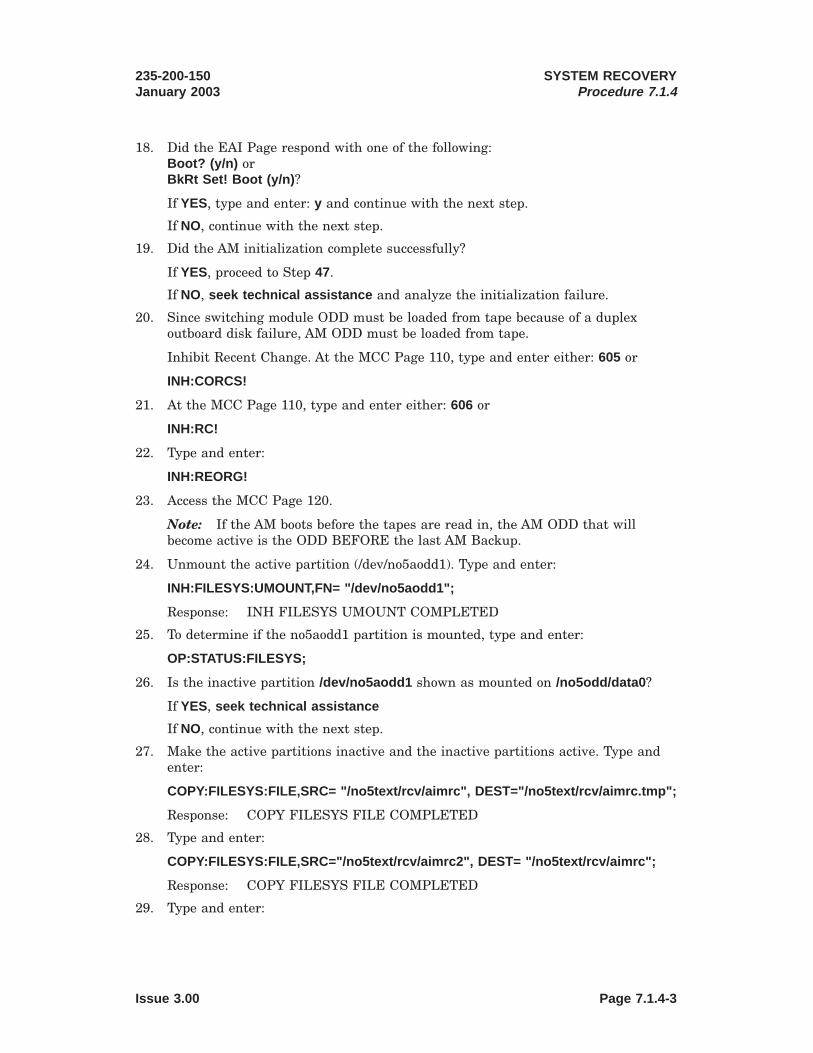
18. Did the EAI Page respond with one of the following:Boot? (y/n) orBkRt Set! Boot (y/n) ?
If YES, type and enter: y and continue with the next step.
If NO, continue with the next step.
19. Did the AM initialization complete successfully?
If YES, proceed to Step 47.
If NO, seek technical assistance and analyze the initialization failure.
20. Since switching module ODD must be loaded from tape because of a duplexoutboard disk failure, AM ODD must be loaded from tape.
Inhibit Recent Change. At the MCC Page 110, type and enter either: 605 or
INH:CORCS!
21. At the MCC Page 110, type and enter either: 606 or
INH:RC!
22. Type and enter:
INH:REORG!
23. Access the MCC Page 120.
Note: If the AM boots before the tapes are read in, the AM ODD that willbecome active is the ODD BEFORE the last AM Backup.
24. Unmount the active partition (/dev/no5aodd1). Type and enter:
INH:FILESYS:UMOUNT,FN= "/dev/no5aodd1";
Response: INH FILESYS UMOUNT COMPLETED
25. To determine if the no5aodd1 partition is mounted, type and enter:
OP:STATUS:FILESYS;
26. Is the inactive partition /dev/no5aodd1 shown as mounted on /no5odd/data0 ?
If YES, seek technical assistance
If NO, continue with the next step.
27. Make the active partitions inactive and the inactive partitions active. Type andenter:
COPY:FILESYS:FILE,SRC= "/no5text/rcv/aimrc", DEST="/no5text/rcv/aimrc.tmp";
Response: COPY FILESYS FILE COMPLETED
28. Type and enter:
COPY:FILESYS:FILE,SRC="/no5text/rcv/aimrc2", DEST= "/no5text/rcv/aimrc";
Response: COPY FILESYS FILE COMPLETED
29. Type and enter:
235-200-150January 2003
SYSTEM RECOVERYProcedure 7.1.4
Issue 3.00 Page 7.1.4-3

COPY:FILESYS:FILE,SRC ="/no5text/rcv/aimrc.tmp"DEST="/no5text/rcv/aimrc2";
Response: COPY FILESYS FILE COMPLETED
30. Type and enter:
CLR:FILESYS:FILE,FN="/no5text/rcv/aimrc.tmp";
Response: CLR FILESYS FILE COMPLETED
31. Load AM ODD. Type and enter:
Response: DUMP:FILE:ALL,FN ="/no5text/bkup/aodd.ptn";
32. Does contents of /no5text/bkup/aodd.ptn agree line-for-line with either of thefollowing:
/dev/no5aodd1/dev/no5dodd1
If YES, continue with the next step.
If NO, seek technical assistance .
33. Type and enter:
COPY:FILESYS:FILE,SRC="/no5text/bkup/aodd.ptn", DEST ="/tmp/tmpodd.ptn";
Response: COPY FILESYS FILE COMPLETED
34. Mount the AM ODD backup tape on the tape drive.
35. To read the AM ODD backup tape into the ODD partitions, type and enter:
EXC:ENVIR:UPROC,FN= "/etc/mkdsk",ARGS= "-i"-"/dev/mt00"-"-d"-"/dev/vtoc"-"-p"-"/tmp/tmpodd.ptn";
Response: EXC ENVIR UPROC COMPLETED
36. Was the set of AM ODD backup tapes read into the AM ODD partitionssuccessfully?
If YES, continue with the next step.
If NO, seek technical assistance
37. Type and enter:
CLR:FILESYS:FILE,FN ="/tmp/tmpodd.ptn";
Response: CLR FILESYS FILE COMPLETED
38. Type and enter:
COPY:FILESYS:FILE,SRC="/no5text/rcv/aimrc", DEST="/no5text/rcv/aimrc.tmp";
Response: COPY FILESYS FILE COMPLETED
39. Type and enter:
COPY:FILESYS:FILE,SRC="/no5text/rcv/aimrc2", DEST="/no5text/rcv/aimrc";
Response: COPY FILESYS FILE COMPLETED
40. Type and enter:
SYSTEM RECOVERYProcedure 7.1.4
235-200-150January 2003
Page 7.1.4-4 Issue 3.00

COPY:FILESYS:FILE,SRC ="/no5text/rcv/aimrc.tmp", DEST="/no5text/rcv/aimrc2";
Response: COPY FILESYS FILE COMPLETED
41. Type and enter:
CLR:FILESYS:FILE,FN="/no5text/rcv/aimrc.tmp";
Response: CLR FILESYS FILE COMPLETED
42. Type and enter:
DUMP:FILE:ALL,FN= "/no5text/rcv/aimrc";
Response: DUMP FILE ALL COMPLETED 1 no5dodd1 is the current disk odd
43. Was no5dodd1 printed in the previous step?
Note: At this point in the procedure, the loading of the AM text and AM ODDtapes is completed. The next step is to perform a system initialization whilerequesting a backout of recent changes. The reason for requesting the backout ofAM recent changes is that any recent change log files which may exist on thedisk will be inconsistent with the Office Dependent Data (ODD) disk image justread into the system. Before performing the system initialization, be sure thatthe Backup Root indicator is SET and the Min Config indicator is clear on theEAI page.
If YES, continue with the next step.
If NO, seek technical assistance .
44. On the EAI page, type and enter: 42;h;54; to boot the AM.
45. Did the EAI Page respond with one of the following:Boot? (y/n) orBkRt Set! Boot (y/n) ?
If YES, type and enter: y and continue with the next step.
If NO, continue with the next step.
46. Did the AM initialization complete (Page 111/112 displayed)?
If YES, continue with the next step.
If NO, seek technical assistance .
47. The AM is now running on the backup root file system with a different AMODD.Now do post-AM recovery actions to recover the switching module ODD andswitching module text (if necessary), and return to the primary root file system.
Go to “Post AM Recovery Cleanup,” Procedure 7.2.
48. STOP. YOU HAVE COMPLETED THIS PROCEDURE.
235-200-150January 2003
SYSTEM RECOVERYProcedure 7.1.4
Issue 3.00 Page 7.1.4-5


7.2 Post AM Recovery Cleanup
OVERVIEW
You have reached this point because the Administrative Module (AM) was booted suchthat further recovery action is required. This procedure will deal with switchingmodule related recoveries. This procedure will also deal with outboard disks that haveexperienced failures that have rendered those disks unusable (duplex disk failure).
The overall objective of this procedure is to have the AM running in the rootconfiguration on the system moving head disks (MHD). If the AM was booted from adisk that was loaded from tape, the AM is running on the backup root partitions. Thebackup root partitions are normally used for recovery from tape situations; therefore,it is necessary to copy the backup root partitions to the root partitions and reboot theAM. If the AM was booted from a disk that was a software backup disk, the systemMHDs must be restored to normal and the software backup disk returned to backupstatus.
Once the office is processing calls and has stabilized, the AM and disks should bereturned to a duplex configuration. Also, the AM backout indicator on Master ControlCenter (MCC) Page 110 should be returned to normal. This is accomplished by firstclearing the recent change log files and then clearing the AM recent change backoutindicator. Also, switching module ODD of the same vintage as the AM ODD must beloaded in from tape so there is consistency between the AM and switching moduleODDs.
If no MHD2/MHD3 text tape (switching module text tape) at the same softwareupdate level as the AM text restored from the backup media is available, install anolder switching module text tape now and obtain a tape of the same software updatelevel as the AM text to install later. The Backout Last Overwrite (BOLO) feature maynot be usable following an AM recovery from tape or Software Backup (SWBU) diskand will not be usable if MHD2/MHD3 must be replaced with a new disk.
Table 7.2-1 — Recovery Actions
AM RECOVERYFROM:
RECOVERYACTION SMTEXT, PUMP
SM
SM TEXT, SMODD PUMP
SM
RECOVERBASE MHD
RESTOREROOT &REBOOT
Original Disk — — — ZAM Text Tape X — — XAM Text & ODDTapes
— X — X
X = Actions that are required.Z = Actions that are required if AM recovered on the backup root.
Post AM Recovery Subprocedure Overview
— Recover the Volume Table Of Contents (VTOC) of any outboard MHD that is newor duplex failed, and initialize Automatic Message Accounting (AMA) Disk Writer.
— Recover the switching module text on the second disk pair if necessary tomaintain consistent software update levels between AM text and switchingmodule text.
235-200-150January 2003
SYSTEM RECOVERYProcedure 7.2
Issue 3.00 Page 7.2-1

— If AM recovered from backup tape or disk, restore switching module ODD fromswitching module ODD tape(s), and pump the switching module.
— Restore primary MHDs.
— If AM recovery was from a software backup disk, restore that disk to sparestatus.
— Allow Power Switch Monitor scanning of software backup disks.
— Restore control units (CU) and all MHDs to duplex.
— LATER: If the AM recovered on the backup root file system, copy backuppartitions to root partitions. Then after duplexing the disks, reboot the AM onroot configuration with 53.
PROCEDURE
1. Follow these subprocedures in the order in which they are presented.
• “Post AM Recovery Cleanup,” Subprocedure 7.2.1.
• “Restore Switching Module Text on Outboard MHDs,” Subprocedure 7.2.2.
• “Restore the Switching Module ODD,” Subprocedure 7.2.3.
• “Recover from BROOT Configuration,” Subprocedure 7.2.4.
SYSTEM RECOVERYProcedure 7.2
235-200-150January 2003
Page 7.2-2 Issue 3.00

7.2.1 Post AM Recovery Cleanup
PROCEDURE
1. Inhibit diagnostic sources until disk restore activities are complete. Type andenter:
INH:DMQ:SRC=ADP;INH:AUD=SODD,FULL;
2. Clear any active diagnostics from the system. Type and enter:
OP:DMQ;
Response: REQUEST ACTIVE0 RST MHD 1 BPH=1 EPH=100SOURCE = ADP PRIORITY = 512STATUS = ACTIVE
REQUEST WAITING
1 RST MHD 3 BPH=1 EPH=100SOURCE = MAN PRIORITY = 0STATUS = WAITING
INHIBIT SOURCES
NONE
OP DMQ COMPLETED
3. If MHD actions are active or waiting, type and enter:
STP:DMQ:MHD=x,zzzzzz;
Where: x = Unit number of MHDzzzzzz = ACTIVE and/or WAITING as per output message fromprevious step.
4. On MCC Page 111, are MHD 2/3 shown as duplexed failed?
If YES, continue with the next step.
If NO, continue with Step 8.
5. At the MCC, write the VTOC file to the MHD being recovered. Type and enter:
EXC:ENVIR:UPROC,FN="/etc/rcvtoc",ARGS=2;
Where: 2 = MHD number to be restored
Response: EXC ENVIR UPROC COMPLETEDvcp: disk copy completedvcp: disk copy completed/etc/rcvtoc VTOC READ AND COMPARESUCCESSFUL
6. Restore MHD 2. Type and enter:
RST:MHD=2
235-200-150January 2003
SYSTEM RECOVERYProcedure 7.2.1
Issue 3.00 Page 7.2.1-1

Where: 2 = MHD number to be restored
Response: RST MHD 2 TASK y MSG STARTEDRST MHD 2 IN PROGRESSRST MHD 2 COMPLETED
7. The AMA partitions must now be cleaned up. Initialize AMA Disk Writer. Typeand enter:
INIT:AM,AMDW1,FPI;
Response: REPT AMA DISK WRITER FOR STREAM ST1RECORDING TO DISK SUSPENDEDREPT AMA DISK WRITER FOR STREAM ST1TERMINATION CODE 2REPT AMA DISK WRITER FOR STREAM ST1ERROR CODE 6REPT AMA DISK WRITER FOR STREAM ST1INITIALIZATION COMPLETEREPT AMA DISK WRITER FOR STREAM ST1RECORDING TO DISK RESUMED
8. Verify software update levels of AM text (/no5text) and switching modulet(/no5text/im). Type and enter:
OP:VERSION;
OP VERSION mm dd, yyyyPARTITION VERSION BWMECD 5ex(x)xx.xx/ 5ex(x)xx.xx BWMnn-nnnn/etc 5ex(x)xx.xx BWMnn-nnnn/unixa 5ex(x)xx.xx BWMnn-nnnn/no5text/im 5ex(x)xx.xx BWMnn-nnnn/no5text 5ex(x)xx.xx BWMnn-nnnn
9. Are the software update levels of /no5text and /no5text/im the same?
If YES, continue with the next step.
If NO, go to “Restore Switching Module Text on Outboard MHDs,” Subprocedure7.2.2, to recover switching module text, then return to the next step.
10. ALL disks containing switching module ODD must be recovered from tape if anyof the following conditions exist:
• AM ODD recovered on an MHD restored from AM ODD backup tapes,
• Any outboard MHD containing switching module ODD was duplexed failed sothat the switching module ODD on that disk is known to be bad.
Do any of these conditions exist?
If YES, go to “Restore the Switching Module ODD,” Subprocedure 7.2.3, torecover switching module ODD, then return to the next step.
If NO, continue with the next step.
SYSTEM RECOVERYProcedure 7.2.1
235-200-150January 2003
Page 7.2.1-2 Issue 3.00

11. Obtain status from Page 141 or type and enter:
OP:SYSSTAT:SM=x;
Response: OP SYSSTAT SUMMARY LAST RECORDL LSM n,n: rrr
Where: rrr = Switching module off-normal status.
12. Using the response from the previous step, does the switching module have aprogress marker status of:
Any Init-in-progress state?INIT ISOLCOMM LOSTISOLATEDSTNDALONE
If YES, continue with the next step.
If NO, proceed to Step 17.
13. For the switching module: type and enter either: 923 or
INIT:SM=a,FI,PUMP;
Where: a = The switching module number.
Response: INIT SM=a LVL=FI SUMMARY EVENT = xxxxxCALL PROCESSING DOWNTIME=x:xx:xxCALLS LOST: STABLE=x TRANSIENT=x
14. Clear forces on MHD and allow the CU to be restored. On EAI page, type andenter: 21 and 23.
15. Allow MHD diagnostics again and restore MHDs to duplex operation. Type andenter:
ALW:DMQ:SRC=ADP;
16. Restart diagnostics if necessary. Type and enter:
OP:DMQ;
17. If MHD diagnostics are not active or waiting, from MCC Page 111, type andenter: 30x to restore the MHDs.
Where: x = MHD Number
Response: RST MHD x TASK y MSG STARTEDRST MHD x IN PROGRESS(will be output every 2 minutes)RST MHD x COMPLETED
18. Was either switching module text or switching module ODD reloaded from tape?
If YES, use “Off-Line Pump for Recovery of a Functional Switching Module,”235-105-250, 5ESS® Switch System Recovery, to off-line pump and switch theswitching module, then return to the next step.
If NO, continue with the next step.
235-200-150January 2003
SYSTEM RECOVERYProcedure 7.2.1
Issue 3.00 Page 7.2.1-3
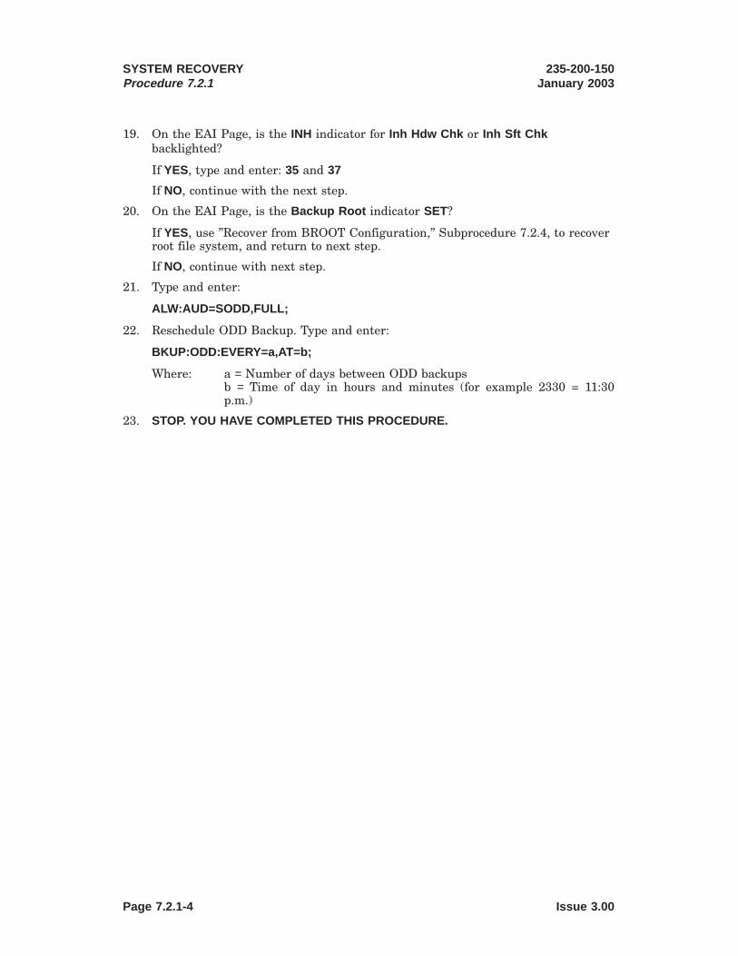
19. On the EAI Page, is the INH indicator for Inh Hdw Chk or Inh Sft Chkbacklighted?
If YES, type and enter: 35 and 37
If NO, continue with the next step.
20. On the EAI Page, is the Backup Root indicator SET?
If YES, use ”Recover from BROOT Configuration,” Subprocedure 7.2.4, to recoverroot file system, and return to next step.
If NO, continue with next step.
21. Type and enter:
ALW:AUD=SODD,FULL;
22. Reschedule ODD Backup. Type and enter:
BKUP:ODD:EVERY=a,AT=b;
Where: a = Number of days between ODD backupsb = Time of day in hours and minutes (for example 2330 = 11:30p.m.)
23. STOP. YOU HAVE COMPLETED THIS PROCEDURE.
SYSTEM RECOVERYProcedure 7.2.1
235-200-150January 2003
Page 7.2.1-4 Issue 3.00

7.2.2 Restore Switching Module Text on Outboard MHDs
OVERVIEW
If an MHD2/MHD3 switching module text tape (/dev/vtoc1) at the same softwareupdate level as the AM text (/dev/vtoc) restored from the backup media is notavailable, install an older tape now and obtain a tape of the same software updatelevel as the /no5text partition to install later.
PROCEDURE
1. Mount the tape on the tape drive.
At the MCC, type and enter: DUMP:BKTAPE:TD="x"
Where: x = Pathname of the tape special device file.
Response: DUMP BKTAPE TD x STARTED
For each logical volume on the tape, the following response appears:
Response: DUMP BKTAPE TD x IN PROGRESSSESSION VOLUME NAME BLOCKS SOURCE DATE
a b c d e f
Where: a = Backup session number.b = Logical volume number.c = Logical volume name.d = Number of blocks for the logical volume.e = Source disk(s) logical volume was written from.f = Date logical volume was written.
After all logical volumes have been processed, the following response appears:
Response: DUMP BKTAPE TD x COMPLETEDCUMULATIVE BLOCKS a
Where: a = Cumulative number of blocks for all logical volumes.
Note the session number and volume number of the SM TEXT backup to be readinto the partitions.
2. Is an STLWS available?
If YES, go to Step 7.
If NO, continue with the next step.
3. At the MCC, type and enter: 194
Response:
235-200-150January 2003
SYSTEM RECOVERYProcedure 7.2.2
Issue 3.00 Page 7.2.2-1

12345678901234567890123456789012123456789012345678901234561234567890123456789012345678901212345678901234567890123456123456789012345678901234567890121234567890123456789012345612345678901234567890123456789012123456789012345678901234561234567890123456789012345678901212345678901234567890123456123456789012345678901234567890121234567890123456789012345612345678901234567890123456789012123456789012345678901234561234567890123456789012345678901212345678901234567890123456123456789012345678901234567890121234567890123456789012345612345678901234567890123456789012123456789012345678901234561234567890123456789012345678901212345678901234567890123456123456789012345678901234567890121234567890123456789012345612345678901234567890123456789012123456789012345678901234561234567890123456789012345678901212345678901234567890123456123456789012345678901234567890121234567890123456789012345612345678901234567890123456789012123456789012345678901234561234567890123456789012345678901212345678901234567890123456123456789012345678901234567890121234567890123456789012345612345678901234567890123456789012123456789012345678901234561234567890123456789012345678901212345678901234567890123456
12345678901234567890123456789012123456789012345678901234561234567890123456789012345678901212345678901234567890123456123456789012345678901234567890121234567890123456789012345612345678901234567890123456789012123456789012345678901234561234567890123456789012345678901212345678901234567890123456
12345678901234567890123456789012123456789012345678901234561234567890123456789012345678901212345678901234567890123456123456789012345678901234567890121234567890123456789012345612345678901234567890123456789012123456789012345678901234561234567890123456789012345678901212345678901234567890123456
123456789012345678901234567890121234567890123456789012345612345678901234567890123456789012123456789012345678901234561234567890123456789012345678901212345678901234567890123456123456789012345678901234567890121234567890123456789012345612345678901234567890123456789012123456789012345678901234561234567890123456789012345678901212345678901234567890123456
Depress PF3 key twice to reconnect to the SCREEN process ifthe Command Message Key (PF3) has been used during this procedure.
What is the desired command?
o) ODBE c) CNIDBOCa) ACCED r) RTAGu) UNIX SHELL Q) TO QUIT
Please enter o,a,u,c, r, or Q:Character mappings
\:, \1, \s, \8, \−, \a, \/, \\, \;, !, $, &, -, @, ?, \,
4. Enter the UNIX1 mode. Type and enter: u
5. Invoke rdldft. Type and enter: /usr/bin/rdldft
Note: When using the MCC, the screens displayed by rdldft will not paint as itdoes when used with an STLWS. Some lines in the screens which follow may notbe displayed. Commands are entered in the upper left corner and displayed nextto the rdldft prompt after pressing the RETURN key.
6. Go to Step 9.
7. Clear the screen with a 120 poke.
8. The tape to be mounted is the switching module text tape for MHD2/MHD3(/dev/vtoc1) with the same software update level marking on the tape label as thesoftware update level of the AM text that was just booted.
Type and enter: RCV:MENU:RDLDFT;
Response:
Please enter the tape drive number.Please enter the number ’0’ for tape drive MT0 or
the number ’1’ for tape drive MT1, etc.:
9. At the RDLDFT display prompt, type and enter: 0
Response:
Please enter the letter ’x’ for SM TEXT orthe letter ’s’ for SM ODD:
10. At the RDLDFT display prompt, type and enter: x to load SM Text.
Response:
What tape volume format is to be used?Please enter ’m’ for Multi-volume format or
’s’ for Single-volume format:
1. Registered trademark in the United States and other countries, licensed exclusively through X/OpenCompany, Limited
SYSTEM RECOVERYProcedure 7.2.2
235-200-150January 2003
Page 7.2.2-2 Issue 3.00

1234567890123456789012345678901212345678901234567890123456123456789012345678901234567890121234567890123456789012345612345678901234567890123456789012123456789012345678901234561234567890123456789012345678901212345678901234567890123456
1234567890123456789012345678901212345678901234567890123456123456789012345678901234567890121234567890123456789012345612345678901234567890123456789012123456789012345678901234561234567890123456789012345678901212345678901234567890123456
123456789012345678901234567890121234567890123456789012345612345678901234567890123456789012123456789012345678901234561234567890123456789012345678901212345678901234567890123456123456789012345678901234567890121234567890123456789012345612345678901234567890123456789012123456789012345678901234561234567890123456789012345678901212345678901234567890123456
1234567890123456789012345678901212345678901234567890123456123456789012345678901234567890121234567890123456789012345612345678901234567890123456789012123456789012345678901234561234567890123456789012345678901212345678901234567890123456123456789012345678901234567890121234567890123456789012345612345678901234567890123456789012123456789012345678901234561234567890123456789012345678901212345678901234567890123456
11. At the RDLDFT display prompt, type and enter: m
Response:
Please enter session number:
12. At the RDLDFT display prompt, type and enter: the session number [1-9] fromStep 1.
Response:
Please enter volume number:
13. At the RDLDFT display prompt, enter 3 for the volume number for SM Text.
Response:
What tape density is to be used?Please enter the number ’8’ for low density or
the number ’0’ for high density:
14. At the RDLDFT display prompt, type and enter: 8 for the low tape densityidentifier.
15. Once the tape density identifier has been selected, the following statement willbe displayed. Observe the statement, then continue with next step.
RDLDFT: SM TEXT tape sequence chosen for /dev/vtoc1 on /dev/mtxxRDLDFT: Please mount the first backup tape on the tape drive
and insure that the ONLINE button is ON.Please enter ’go’ after the tape is mounted:
Note: If this statement is not received within a few seconds, monitor ROP forREPT FMGR UMOUNT FAILED output message and seek technical assistanceto identify process that is blocking UNMOUNT of SM text file system.
16. Make sure the switching module text tape is mounted, ensure that the tape driveONLINE button is ON, and then type and enter: : go
Note: As the tape is being loaded to disk, a tape load forward progressing dotwill appear on the terminal approximately every 30 seconds. Once the tape loadhas completed, the following message will be printed.
Response: RDLDFT COMPLETEDRCV MENU RDLDFT COMPLETED
17. Was the RDLDFT COMPLETED message received?
If YES, switching module text has been loaded. Continue with the next step.
If NO, seek technical assistance .
18. Was rdldft invoked from the MCC?
If YES, exit from UNIX shell, type and enter: q and exit from the MCC Page 194,type and enter: q
235-200-150January 2003
SYSTEM RECOVERYProcedure 7.2.2
Issue 3.00 Page 7.2.2-3

If NO, continue with the next step.
19. Did the switching module text backup tape read into the text partitionssuccessfully?
If YES, STOP. YOU HAVE COMPLETED THIS PROCEDURE.
If NO, seek technical assistance.
SYSTEM RECOVERYProcedure 7.2.2
235-200-150January 2003
Page 7.2.2-4 Issue 3.00

1234567890123456789012345678901212345678901234567890123456123456789012345678901234567890121234567890123456789012345612345678901234567890123456789012123456789012345678901234561234567890123456789012345678901212345678901234567890123456123456789012345678901234567890121234567890123456789012345612345678901234567890123456789012123456789012345678901234561234567890123456789012345678901212345678901234567890123456123456789012345678901234567890121234567890123456789012345612345678901234567890123456789012123456789012345678901234561234567890123456789012345678901212345678901234567890123456123456789012345678901234567890121234567890123456789012345612345678901234567890123456789012123456789012345678901234561234567890123456789012345678901212345678901234567890123456123456789012345678901234567890121234567890123456789012345612345678901234567890123456789012123456789012345678901234561234567890123456789012345678901212345678901234567890123456123456789012345678901234567890121234567890123456789012345612345678901234567890123456789012123456789012345678901234561234567890123456789012345678901212345678901234567890123456
7.2.3 Restore the Switching Module ODD
OVERVIEW
The following steps will install the switching module ODD disk image from backupswitching module ODD tapes.
PROCEDURE
1. Mount the tape on the tape drive.
At the MCC, type and enter: DUMP:BKTAPE:TD="x"
Where: x = Pathname of the tape special device file.
Response: DUMP BKTAPE TD x STARTED
For each logical volume on the tape, the following response appears:
Response: DUMP BKTAPE TD x IN PROGRESSSESSION VOLUME NAME BLOCKS SOURCE DATE
a b c d e f
Where: a = Backup session number.b = Logical volume number.c = Logical volume name.d = Number of blocks for the logical volume.e = Source disk(s) logical volume was written from.f = Date logical volume was written.
After all logical volumes have been processed, the following response appears:
Response: DUMP BKTAPE TD x COMPLETEDCUMULATIVE BLOCKS a
Where: a = Cumulative number of blocks for all logical volumes.
Note the session number and volume number of the SM TEXT backup to be readinto the partitions.
2. Is an STLWS available?
If YES, go to Step 7.
If NO, continue with the next step.
3. At the MCC, type and enter: 194
Response:
Depress PF3 key twice to reconnect to the SCREEN process ifthe Command Message Key (PF3) has been used during this procedure.
What is the desired command?
o) ODBE c) CNIDBOCa) ACCED r) RTAGu) UNIX SHELL Q) TO QUIT
Please enter o,a,u,c, r, or Q:Character mappings
\:, \1, \s, \8, \−, \a, \/, \\, \;, !, $, &, -, @, ?, \,
235-200-150January 2003
SYSTEM RECOVERYProcedure 7.2.3
Issue 3.00 Page 7.2.3-1

123456789012345678901234567890121234567890123456789012345612345678901234567890123456789012123456789012345678901234561234567890123456789012345678901212345678901234567890123456123456789012345678901234567890121234567890123456789012345612345678901234567890123456789012123456789012345678901234561234567890123456789012345678901212345678901234567890123456
12345678901234567890123456789012123456789012345678901234561234567890123456789012345678901212345678901234567890123456123456789012345678901234567890121234567890123456789012345612345678901234567890123456789012123456789012345678901234561234567890123456789012345678901212345678901234567890123456
123456789012345678901234567890121234567890123456789012345612345678901234567890123456789012123456789012345678901234561234567890123456789012345678901212345678901234567890123456123456789012345678901234567890121234567890123456789012345612345678901234567890123456789012123456789012345678901234561234567890123456789012345678901212345678901234567890123456
123456789012345678901234567890121234567890123456789012345612345678901234567890123456789012123456789012345678901234561234567890123456789012345678901212345678901234567890123456
4. Enter UNIX1 shell. Type and enter: u
5. Invoke rdldft. Type and enter: /usr/bin/rdldft
Note: When using the MCC, the screens displayed by rdldft will not paint as itdoes when used with an STLWS. Some lines in the screens which follow may notbe displayed. Commands are entered in the upper left corner and displayed nextto the rdldft prompt after pressing the RETURN key.
6. Go to Step 9.
7. Clear the screen, type and enter: 120
8. At the command prompt, start the load disk from tape program.
The Volume Table Of Contents (VTOC) to be selected must be the same as the/dev/vtocx on each of the switching module ODD backup tape labels. Theswitching module ODD tape must have been made in the same software releasebackup session as the AM ODD tape which was used in the recovery.
Type and enter: RCV:MENU:RDLDFT;
Response:
Please enter the tape drive number.Please enter the number ’0’ for tape drive MT0 or
the number ’1’ for tape drive MT1, etc.:
9. At the RDLDFT display prompt, type and enter: 0
Response:
Please enter the letter ’x’ for SM TEXT orthe letter ’s’ for SM ODD:
10. At the RDLDFT display prompt, type and enter: s to load SM ODD.
Response:
What tape volume format is to be used?Please enter ’m’ for Multi-volume format or
’s’ for Single-volume format:
11. At the RDLDFT display prompt, type and enter: m
Response:
Please enter session number:
12. At the RDLDFT display prompt, type and enter: the session number [1-9] fromStep 1.
Response:
1. Registered trademark in the United States and other countries, licensed exclusively through X/OpenCompany, Limited
SYSTEM RECOVERYProcedure 7.2.3
235-200-150January 2003
Page 7.2.3-2 Issue 3.00

1234567890123456789012345678901212345678901234567890123456123456789012345678901234567890121234567890123456789012345612345678901234567890123456789012123456789012345678901234561234567890123456789012345678901212345678901234567890123456
12345678901234567890123456789012123456789012345678901234561234567890123456789012345678901212345678901234567890123456123456789012345678901234567890121234567890123456789012345612345678901234567890123456789012123456789012345678901234561234567890123456789012345678901212345678901234567890123456
123456789012345678901234567890121234567890123456789012345612345678901234567890123456789012123456789012345678901234561234567890123456789012345678901212345678901234567890123456123456789012345678901234567890121234567890123456789012345612345678901234567890123456789012123456789012345678901234561234567890123456789012345678901212345678901234567890123456123456789012345678901234567890121234567890123456789012345612345678901234567890123456789012123456789012345678901234561234567890123456789012345678901212345678901234567890123456123456789012345678901234567890121234567890123456789012345612345678901234567890123456789012123456789012345678901234561234567890123456789012345678901212345678901234567890123456
1234567890123456789012345678901212345678901234567890123456123456789012345678901234567890121234567890123456789012345612345678901234567890123456789012123456789012345678901234561234567890123456789012345678901212345678901234567890123456123456789012345678901234567890121234567890123456789012345612345678901234567890123456789012123456789012345678901234561234567890123456789012345678901212345678901234567890123456
Please enter volume number:
13. At the RDLDFT display prompt, type and enter: the volume number [4-9] fromStep 1.
Response:
What tape density is to be used?Please enter the number ’8’ for low density or
the number ’0’ for high density:
14. At the RDLDFT display prompt, type and enter: 8 for the low tape densityidentifier.
Response:
What vtoc is to be used?Please enter ONLY one number for the below choices:
1 for /dev/vtoc12 for /dev/vtoc23 for /dev/vtoc34 for /dev/vtoc45 for /dev/vtoc56 for /dev/vtoc6:
15. At the RDLDFT display prompt, type and enter: 1
16. Once the VTOC has been selected, the following statement will be displayed.Observe the statement, then continue with the next step. If this statement is notreceived within a few seconds, then monitor ROP for REPT FMGR UMOUNTFAILED output message and seek technical assistance to identify process thatis blocking UNMOUNT of SM ODD file system.
Response:
RDLDFT: SM ODD tape sequence chosen for /dev/vtoc1 on /dev/mtxxRDLDFT: Please mount the first backup tape on the tape drive
and insure that the ONLINE button is ON.Please enter ’go’ after the tape is mounted:
17. Make sure the switching module ODD backup tape is mounted, ensure that thetape drive ONLINE button is ON, and then enter the following: go
Note: As the tape is being loaded to disk, a tape load forward progression dotwill appear on the terminal every 30 seconds. Once the tape load has completed,the following messages will be printed:
RDLDFT COMPLETEDRCV MENU RDLDFT COMPLETED
18. Was the RDLDFT COMPLETED message received?
If YES, the tape load using the VTOC selected in Step 15 has completed; continuewith the next step.
If NO, seek technical assistance .
235-200-150January 2003
SYSTEM RECOVERYProcedure 7.2.3
Issue 3.00 Page 7.2.3-3

19. Was rdldft invoked from the MCC?
If YES, exit from UNIX shell, type and enter: q and exit from the MCC Page 194,type and enter: q
If NO, continue with the next step.
20. Did the switching module ODD backup tape read into the ODD partitionssuccessfully?
If YES, continue with the next step.
If NO, seek technical assistance.
21. Type and enter:
EXC:ENVIR:UPROC,FN="/no5text/bkup/clrlg";
Note: The Recent Change (RC) and Customer-Originated Recent Change(CORC) log files in the system are no longer consistent with the ODD just readin from tape. The AM Backout indicator should be returned to normal. This isaccomplished by first clearing the RC and CORC recent change log files (AM andswitching module) and then clearing the AM recent change backout indicator.
Response: EXC ENVIR UPROC /no5text/bkup/clrlg STOPPED rm:cni directoryOREXC ENVIR UPROC STOPPED (If log files do not exist) rm *non-existent
22. Type and enter:
STP:EXC:ANY,FN="/no5text/rcv/lglog",UCL;
Response: REPT ULARP ATTEMPTING TO RESTART LGLOG xx STOP EXCANY COMPLETED
23. Clear backup schedule. Type and enter:
CLR:ODDBKUP;
Response: CLR ODDBKUP COMPLETED
24. Type and enter:
EXC:ODDRCVY=SKIPLOG,AM;
Warning: Inappropriate use of this message may interrupt or degradeapplication service. Refer to 235-600-700/750, Input/Output MessagesManual.
Response: EXC ODDRCVY=SKIPLOG AM COMPLETED
25. Type and enter: 521 to clear RC BKOUT box on MCC Page 110.
Response: RC BKOUT box clears.
Note: The AM is currently running on a different version of the ODD than theswitching module. To correct this situation, the switching module must beinitialized.
26. STOP. YOU HAVE COMPLETED THIS PROCEDURE. Return to “Post AMRecovery Cleanup,” Subprocedure 7.2.1.
SYSTEM RECOVERYProcedure 7.2.3
235-200-150January 2003
Page 7.2.3-4 Issue 3.00

7.2.4 Recover from BROOT Configuration
OVERVIEW
Warning: The AM is currently running on the backup root configuration.Therefore, ECD recent changes should not be made to the root or rootdmlycopies of the ECD/SG database until this procedure is completed.
Note: The following steps should be performed during a low-traffic period. Theobjective is to have the AM running on the root configuration. This is accomplished bycopying the backup root partitions to the root partitions and booting the AM.
PROCEDURE
1. Type and enter:
DUMP:FILE:ALL,FN="/no5text/bkup/prim.ptn";
Response: DUMP FILE ALL COMPLETEContents of /no5text/bkup/prim.ptn printed:/dev/root/dev/db/dev/etc/dev/boot
2. Type and enter:
DUMP:FILE:ALL,FN="/no5text/bkup/bkup.ptn";
Response: DUMP FILE ALL COMPLETEContents of /no5text/bkup/bkup.ptn printed:/dev/broot/dev/bdb/dev/betc/dev/boot
3. Do the contents of /no5text/bkup/prim.ptn and /no5text/bkup/bkup.ptn agree withthe responses listed in Steps 1 and 2?
If YES, continue with the next step.
If NO, STOP. DO NOT CONTINUE. Seek technical assistance.
4. Both MHD0 and MHD1 must be active at this point. Type and enter:
COPY:PTN:ALL,SRC="/no5text/bkup/bkup.ptn",DEST="/no5text/bkup/prim.ptn";
Response: RMV MHD x TASK y MSG STARTEDRMV MHD x COMPLETEDRST MHD x TASK y MSG STARTEDRST MHD x IN PROGRESS (is output every 2 minutes)RST MHD x COMPLETEDCOPY PTN FILE COMPLETEDxxxx BLOCKS COPIED (repeated 4 times)
5. On EAI page, type and enter: 31 to clear the backup configuration.
6. On EAI page, type and enter: 53 to boot the AM.
7. Is the response to the previous step boot? (y/n) ?
If YES, type and enter y and continue.
235-200-150January 2003
SYSTEM RECOVERYProcedure 7.2.4
Issue 3.00 Page 7.2.4-1

If NO, continue with the next step.
8. Did the initialization complete?
If YES, continue with the next step.
If NO, analyze the initialization failure.
9. STOP. YOU HAVE COMPLETED THIS PROCEDURE. Return to “Post AMRecovery Cleanup,” Subprocedure 7.2.1
SYSTEM RECOVERYProcedure 7.2.4
235-200-150January 2003
Page 7.2.4-2 Issue 3.00

7.3 Establish Communication with an Isolated Switching Module
OVERVIEW
This procedure is used to recover an isolated switching module. The loss ofcommunication can be indicated on MCC display Page 1800,x by one of the followingstatus indications: COMM LOST, INIT PEND, STNDALONE, or ISOLATED. Tosimplify this procedure, all of these states will be referred to as COMM LOST.
It should be noted that MCC display Page 1800,x is partially updated from theswitching module. When AW/switching module communication is lost, this page willdisplay the AW’s stored information about the switching module. Therefore, not allindicators on the page will reflect the true status of the unit when the switchingmodule has lost communication. When AW/switching module communication isrestored, the page will be updated to reflect the current status of the unit. Followingeach recovery action specified by this procedure, pause briefly to allow the switchingmodule to reestablish communication (if possible) and update the MCC display.
PROCEDURE
1. Perform a visual check to ensure that the Ethernet1 cabling between theswitching module and the Administrative Workstation is intact.
2. On MCC Page 111/112, is the communication link to the switching modulebroken?
If YES, continue with Step 3.
If NO, STOP. YOU HAVE COMPLETED THIS PROCEDURE
3. At the MCC Page 1800,x, type and enter: 403 to manually isolate the switchingmodule.
Response: ISOLATE? (y/n).
Type and enter: y
Response: SET present in box 03.
4. At the MCC Page 1800,x, type and enter: 503 to clear the manual isolation. Wait3 minutes.
Response: SET cleared in box 03.
5. On the MCC Page 111/112, is the communication link to the switching modulebroken?
If YES, continue with Step 6.
If NO, STOP. YOU HAVE COMPLETED THIS PROCEDURE .
6. At the MCC Page 1800,x, type and enter: ORD:CPI=x,CMD=CLR,UCL; to clearforces on the switching module.
Where: x = The switching module number.
1. Registered trademark of Xerox Corporation.
235-200-150June 2004
SYSTEM RECOVERYProcedure 7.3
Issue 3.00J Page 7.3-1
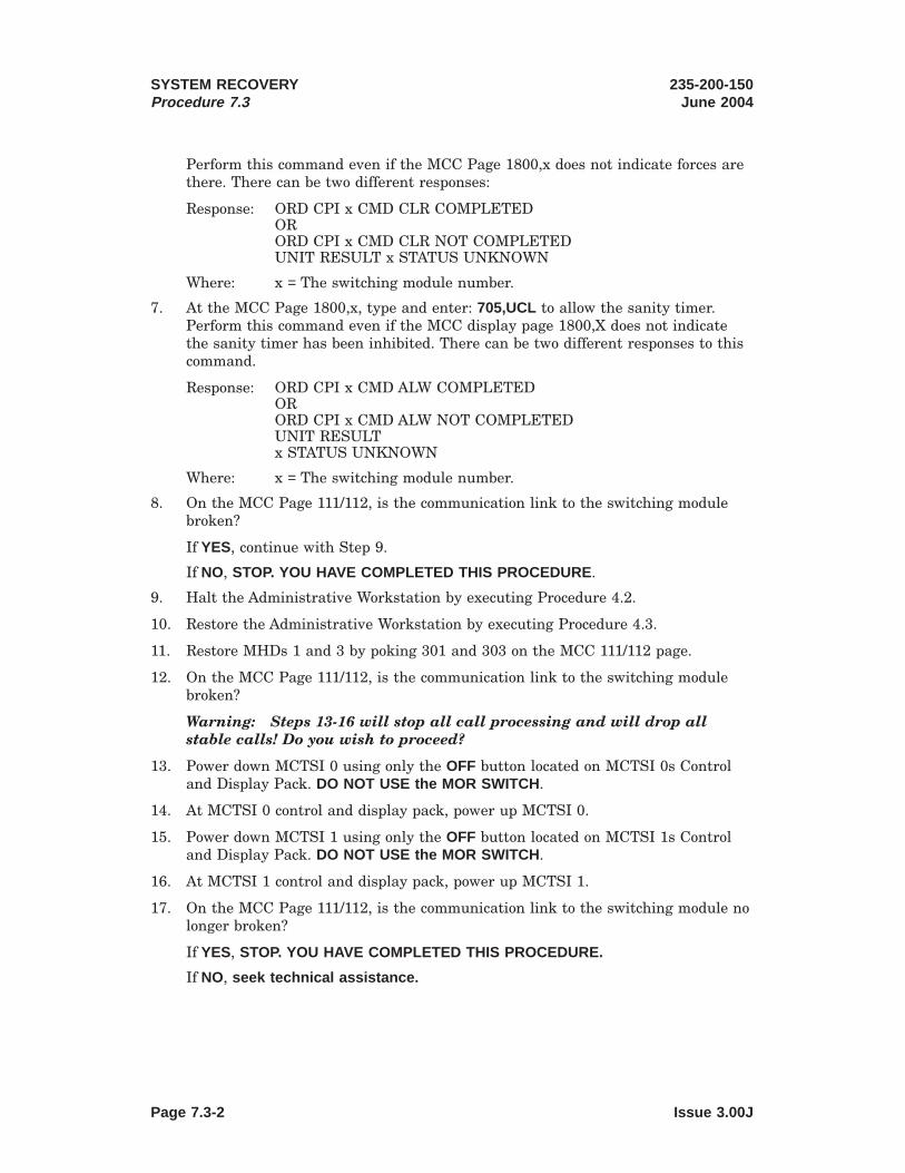
Perform this command even if the MCC Page 1800,x does not indicate forces arethere. There can be two different responses:
Response: ORD CPI x CMD CLR COMPLETEDORORD CPI x CMD CLR NOT COMPLETEDUNIT RESULT x STATUS UNKNOWN
Where: x = The switching module number.
7. At the MCC Page 1800,x, type and enter: 705,UCL to allow the sanity timer.Perform this command even if the MCC display page 1800,X does not indicatethe sanity timer has been inhibited. There can be two different responses to thiscommand.
Response: ORD CPI x CMD ALW COMPLETEDORORD CPI x CMD ALW NOT COMPLETEDUNIT RESULTx STATUS UNKNOWN
Where: x = The switching module number.
8. On the MCC Page 111/112, is the communication link to the switching modulebroken?
If YES, continue with Step 9.
If NO, STOP. YOU HAVE COMPLETED THIS PROCEDURE .
9. Halt the Administrative Workstation by executing Procedure 4.2.
10. Restore the Administrative Workstation by executing Procedure 4.3.
11. Restore MHDs 1 and 3 by poking 301 and 303 on the MCC 111/112 page.
12. On the MCC Page 111/112, is the communication link to the switching modulebroken?
Warning: Steps 13-16 will stop all call processing and will drop allstable calls! Do you wish to proceed?
13. Power down MCTSI 0 using only the OFF button located on MCTSI 0s Controland Display Pack. DO NOT USE the MOR SWITCH .
14. At MCTSI 0 control and display pack, power up MCTSI 0.
15. Power down MCTSI 1 using only the OFF button located on MCTSI 1s Controland Display Pack. DO NOT USE the MOR SWITCH .
16. At MCTSI 1 control and display pack, power up MCTSI 1.
17. On the MCC Page 111/112, is the communication link to the switching module nolonger broken?
If YES, STOP. YOU HAVE COMPLETED THIS PROCEDURE.
If NO, seek technical assistance.
SYSTEM RECOVERYProcedure 7.3
235-200-150June 2004
Page 7.3-2 Issue 3.00J

Distinctive Remote Module (DRM)
CONTENTS PAGE
8. GROWTH AND DEGROWTH . . . . . . . . . . . . . . . . . . 8-1
8.1 Perform Virtual TTY Growth . . . . . . . . . . . . . . . 8.1-1
8.2 Perform Virtual TTY Controller Growth . . . . . . . . . . . 8.2-1
8.3 Perform STLWS Growth . . . . . . . . . . . . . . . . . 8.3-1
8.4 Perform RC/V Terminal Growth . . . . . . . . . . . . . . 8.4-1
8.5 Grow MCC Dial-Up Modem Access . . . . . . . . . . . . . 8.5-1
8.6 Grow Remote Sun Console Dial-Up Modem Access . . . . . . 8.6-1
8.7 Perform SCANS Data Link Growth . . . . . . . . . . . . . 8.7-1
8.8 Perform AMA Data Link Growth . . . . . . . . . . . . . . 8.8-1
8.9 Perform SCC Data Link Growth . . . . . . . . . . . . . . 8.9-1
8.10 Perform ConnectVu (ATPRC) Data Link Growth . . . . . . . . 8.10-1
8.11 Perform TDMS/EADAS Data Link Growth . . . . . . . . . . 8.11-1
8.11.1 Grow in TDMS/EADAS Data Link in ECD . . . . . . . 8.11.1-1
8.11.2 Update RC/V 8.1 for TDMS/EADAS Data Link . . . . . . 8.11.2-1
8.11.3 Connect Hardware for TDMS/EADAS Data Link . . . . . 8.11.3-1
8.11.4 Define TDMS/EADAS Port on TDMS System . . . . . . 8.11.4-1
8.11.5 Initialize TDMS/EADAS Processes . . . . . . . . . . 8.11.5-1
8.11.6 Restore TDMS/EADAS Data Link to Service . . . . . . 8.11.6-1
8.11.7 Verify Operation of TDMS/EADAS Data Link . . . . . . 8.11.7-1
8.11.8 Backup Office Dependent Data . . . . . . . . . . . 8.11.8-1
8.12 Perform RMAS Data Link Growth . . . . . . . . . . . . . 8.12-1
8.12.1 Grow in RMAS Data Link in ECD . . . . . . . . . . . 8.12.1-1
8.12.2 Connect Hardware for RMAS Data Link . . . . . . . . 8.12.2-1
8.12.3 Configure RMAS RC Access . . . . . . . . . . . . 8.12.3-1
235-200-150August 2004
GROWTH AND DEGROWTH
Issue 3.00K Page 8-i
8.12-1
8 . 1 1 - 1
8.10-1
8.9-1
8.8-1
8.7-1
8.6-1
8.5-1
8.4-1
8.3-1
8.2-1
8.1-1
8 - 1

8.12.4 Verify Operation of RMAS Data Link . . . . . . . . . 8.12.4-1
8.13 Perform Traffic Printer Growth . . . . . . . . . . . . . . 8.13-1
8.14 Perform Office Record Printer Growth . . . . . . . . . . . 8.14-1
8.14.1 Update the Office Record Printer Baud Rate . . . . . . 8.14.1-1
8.15 Perform Virtual TTY Controller Degrowth . . . . . . . . . . 8.15-1
8.16 Perform Virtual TTY Degrowth . . . . . . . . . . . . . . . 8.16-1
8.17 Perform STLWS Degrowth . . . . . . . . . . . . . . . . 8.17-1
8.18 Perform RC/V Terminal Degrowth . . . . . . . . . . . . . 8.18-1
8.19 Perform SCC Data Link Degrowth . . . . . . . . . . . . . 8.19-1
8.20 Perform Traffic Printer Degrowth . . . . . . . . . . . . . 8.20-1
8.21 Perform Office Record Printer Degrowth . . . . . . . . . . 8.21-1
LIST OF FIGURES
Figure 8.3-1 — STLWS Installation ( Netra t 1120) . . . . . . . . . . . 8.3-5
Figure 8.3-2 — STLWS Installation ( Netra 20) . . . . . . . . . . . . . 8.3-5
Figure 8.3-3 — STLWS Installation ( Netra 240) . . . . . . . . . . . . 8.3-6
Figure 8.4-1 — Recent Change Terminal Installation ( Netra t 1120) . . . . 8.4-3
Figure 8.4-2 — Recent Change Terminal Installation ( Netra 20) . . . . . . 8.4-3
Figure 8.4-3 — Recent Change Terminal Installation ( Netra 240) . . . . . 8.4-4
Figure 8.5-1 — Dial-Up MCC Hardware Connections . . . . . . . . . . 8.5-4
Figure 8.6-1 — Dial-Up Sun Console Hardware Connections . . . . . . . 8.6-4
Figure 8.7-1 — SCANS Data Link Hardware Installation ( Netra t 1120) . . . 8.7-2
Figure 8.7-2 — SCANS Data Link Hardware Installation ( Netra 20) . . . . . 8.7-3
Figure 8.7-3 — SCANS Data Link Hardware Installation ( Netra 240) . . . . 8.7-4
Figure 8.8-1 — AMA Data Link Hardware Connection ( Netra t 1120) . . . . 8.8-3
Figure 8.8-2 — AMA Data Link Hardware Installation ( Netra 20) . . . . . . 8.8-3
Figure 8.8-3 — AMA Data Link Hardware Installation ( Netra 240) . . . . . 8.8-4
Figure 8.9-1 — SCC Data Link Hardware Connection ( Netra t 1120) . . . . 8.9-4
GROWTH AND DEGROWTH 235-200-150August 2004
Page 8-ii Issue 3.00K
8.9-4
8.8-4
8.8-3
8.8-3
8.7-4
8.7-3
8.7-2
8.6-4
8.5-4
8.4-4
8.4-3
8.4-3
8.3-6
8.3-5
8.3-5
8.21-1
8.20-1
8.19-1
8.18-1
8.17-1
8.16-1
8.15-1
8.14-1
8.13-1

Figure 8.9-2 — SCC Data Link Hardware Connection ( Netra 20). . . . . . 8.9-4
Figure 8.9-3 — SCC Data Link Hardware Connection ( Netra 240) . . . . . 8.9-5
Figure 8.10-1 — ATPRC Data Link Hardware Connection ( Netra t 1120) . . . 8.10-2
Figure 8.10-2 — ATPRC Data Link Hardware Connection ( Netra 20) . . . . 8.10-3
Figure 8.10-3 — ATPRC Data Link Hardware Connection ( Netra 240). . . . 8.10-4
Figure 8.11.3-1 — DIP Shunt Settings for IC456A-R2 . . . . . . . . . . 8.11.3-1
Figure 8.11.3-2 — Wiring Diagram for TDMS/EADAS or RMAS DataLink ( Netra t 1120) . . . . . . . . . . . . . . . . 8.11.3-2
Figure 8.11.3-3 — Wiring Diagram for TDMS/EADAS or RMAS DataLink ( Netra 20). . . . . . . . . . . . . . . . . . 8.11.3-2
Figure 8.11.3-4 — Wiring Diagram for TDMS/EADAS or RMAS DataLink ( Netra 240) . . . . . . . . . . . . . . . . . 8.11.3-3
Figure 8.13-1 — Traffic Printer Installation ( Netra t 1120) . . . . . . . . 8.13-3
Figure 8.13-2 — Traffic Printer Installation ( Netra 20) . . . . . . . . . . 8.13-3
Figure 8.13-3 — Traffic Printer Installation ( Netra 240) . . . . . . . . . 8.13-4
Figure 8.14-1 — Office Record Printer Installation ( Netra t 1120) . . . . . 8.14-3
Figure 8.14-2 — Office Record Printer Installation ( Netra 20) . . . . . . . 8.14-3
Figure 8.14-3 — Office Record Printer Installation ( Netra 240) . . . . . . 8.14-4
LIST OF TABLES
Table 8.3-1 — Netra b t 1120 and Netra 20 Terminal Locations . . . . . . 8.3-3
Table 8.3-2 — Netra 240 Terminal Locations . . . . . . . . . . . . . 8.3-4
Table 8.5-1 — Dial-Up MCC Hardware Requirements . . . . . . . . . . 8.5-1
Table 8.6-1 — Dial-Up Sun Console Hardware Requirements . . . . . . . 8.6-1
235-200-150August 2004
GROWTH AND DEGROWTH
See note(s) at end of table.
Issue 3.00K Page 8-iii
8.6-1
8.5-1
8.3-4
8.3-3
8.14-4
8.14-3
8.14-3
8.13-4
8.13-3
8.13-3
8.10-4
8.10-3
8.10-2
8.9-5
8.9-4


8. GROWTH AND DEGROWTH
Overview
Note: Although procedure steps involving software commands can be performed viathe ASM (via an OA&M cut-through), someone must be present at the DRM office toperform any hardware portions.
The term growth, relative to switch hardware, refers to the addition of equipmentunits to the office and/or the expansion of equipment units already present. The termdegrowth refers to the removal of equipment units and the removal of packs or circuitsfrom an equipment unit. All of the equipment which may be grown must also beconsidered for degrowth. The procedures in this chapter refer to hardware in the DRMoffice.
For more information on switch growth and degrowth, see 235-105-231, 5ESS® SwitchHardware Change Procedures - Growth and 235-105-331, 5ESS Switch HardwareChange Procedures - Degrowth.
235-200-150August 2004
GROWTH AND DEGROWTH
See note(s) at end of table.
Issue 3.00K Page 8-1


8.1 Perform Virtual TTY Growth
OVERVIEW
This procedure is used to grow a virtual TTY. For more information, see 235-600-315,5ESS® Switch ECD/SG Database Manual.
PROCEDURE
1. Enter UNIX1 RTR Recent Change and Verify.
(a) Is MCC or STLWS terminal to be used?For MCC, proceed to Step b.For STLWS proceed to Step i.
(b) At MCC, ensure terminal is in command mode.
(c) At MCC, do Steps d through h.
(d) Type and enter: 199
Response: RCV PARAMETER INFO page displayed with cursor at 1.database_name
(e) Type and enter: incore
Response: 2. review only
(f) Type and enter: n
Response: 3. journaling
(g) Type and enter: *
Response: RCV INITIALIZATION IN PROGRESS message displayed.UNIX RTR RCV (ODIN) - Data Entry page displayed.
(h) You have completed Enter UNIX RTR Recent Change and Verify, proceed toStep 2.
(i) At STLWS terminal, type and enter: RCV:MENU:DATA,RCVECD
Response: RCV ECD PARAMETER INFO page displayed with cursor at 1.database_name
(j) Type and enter: incore
Response: 2. review only
(k) Type and enter: n
Response: 3. journaling
(l) Type and enter: *
Response: RCV INITIALIZATION IN PROGRESS message displayed.UNIX RTR RCV (ODIN) - Data Entry page displayed. Cursorat Enter Form Name:
2. Enter high-level forms.
1. Registered trademark in the United States and other countries, licensed exclusively through X/OpenCompany, Limited.
235-200-150January 2003
GROWTH AND DEGROWTHProcedure 8.1
See note(s) at end of table.
Issue 3.00 Page 8.1-1

(a) Type and enter: toggle
Response: Will take you to the high-level forms.
3. Insert virtual TTY data.
Note: An ! may be entered any time prompted to abort the form and return tothe state when the form was started.
(a) Type and enter: vttyadd
Response: vttyadd form displayed. Cursor at 1.vtty_name:
(b) Type and enter the following data:
1.vtty_name: enter TTY name (see the following TTYNAMES list)
2.shareda: enter y or n3.portb: enter 0, 1, 2, or 34.vttyc_number enter VTTYC controller numberNote(s):a. VTTY7, VTTY23, VTTY43, and VTTY45 will always be inserted as non-shared
VTTYs.b. To determine the port availability on VTTYC, at a selected terminal, type and
enter the command: OP:CFGSTAT:VIOP; .
TTY NAMES
VTTY0 or tty!VTTY2 or tty#VTTY7 or ttyh or VTRAFFPRTVTTY9 or ttyjVTTY10 or ttykVTTY11 or ttylVTTY12 or ttymVTTY13 or ttynVTTY14 or ttyoVTTY22 or ttywVTTY23 or tty8 or VBALANCEVTTY28 or ttyCVTTY29 or ttyDVTTY30 or ttyEVTTY31 or ttyFVTTY32 or ttyGVTTY33 or ttyHVTTY34 or ttyIVTTY43 or ttyR or VOFFRECPRTVTTY45 or ttyT or VCOTVTTY50 or ttyYVTTY56 or tty%VTTY57 or tty’VTTY58 or tty&VTTY59 or tty(VTTY60 or tty_VTTY61 or tty[VTTY62 or ttyJVTTY63 or ttyVVTTY64 or ttyWVTTY65 or ttyXVTTY66 or ttyZ
GROWTH AND DEGROWTHProcedure 8.1
235-200-150January 2003
Page 8.1-2 Issue 3.00

(c) Type and enter: i
Note: An error message will be displayed if you have a physical TTY withthe same TTY letter as the VTTY being grown. Select another VTTY ordegrow the physical TTY. Refer to 235-105-331, 5ESS Switch HardwareChange Procedures — Degrowth or 235-600-315, 5ESS Switch ECD/SGDatabase Manual.
(d) First prompt: Remove VTTYC/VTTY x from service. Enter CARRIAGERETURN to continue. At DRM MCC terminal, type and enter command:RMV:[VTTYC,VTTY]=x
Where: x = VTTYC/VTTY number of the previous logical unit.
Response: RMV [VTTYC,VTTY] x COMPLETED
(e) Second prompt: Restore VTTYC/VTTY x to service. Enter CARRIAGERETURN to continue. At DRM MCC terminal, type and enter command:RST:[VTTYC,VTTY]=x
Where: x = VTTYC/VTTY number of the previous logical unit.
Response: RST [VTTYC,VTTY] x COMPLETED
(f) Third prompt: Restore VTTY x to service. Enter CARRIAGE RETURN tocontinue. At DRM MCC terminal, type and enter command: RST:VTTY=x
Where: x = appropriate VTTY number.
Response: RST VTTY x COMPLETED
(g) The low-level forms will now be added automatically.
Response: FORM INSERTED
4. Exit high-level forms.
(a) Type and enter: <
Response: Exit the vttyadd form UNIX RTR RCV (ODIN) - Data Entrypage displayed. Cursor at Enter Form Name:
(b) Type and enter: toggle
Response: Will take you to the low-level forms.
5. Backup Incore ECD to disk.
(a) Type and enter: activate
Response: Activate form displayed with cursor at 1.copy_inc_to_disk:YES
(b) Enter CARRIAGE RETURN
Response: ODIN will request the action desired.
(c) Type and enter: e
Response: ODIN returns to the UNIX RTR (ODIN) - Data Entry page.
(d) Type and enter: <
Response: RCV ECD COMPLETED
6. Change Security (optional).
235-200-150January 2003
GROWTH AND DEGROWTHProcedure 8.1
Issue 3.00 Page 8.1-3

(a) At DRM MCC, type and enter:SET:RCACCESS,TTY="xxxx",ACCESS=a;
Where: a = Value obtained from the 235-600-700, Input MessagesManualxxxx = TTY name from TTY NAMES list in Step 3b (forexample, if growing VTTY12, xxxx = ttym)
(b) Check the access code, type and enter: OP:RCACCESS,TTY="xxxx"
Where: xxxx = TTY name from TTY NAMES list in Step 3b (forexample, if growing VTTY12, xxxx = ttym)
Response: The access code will be returned in hexadecimal.
7. Backup primary disk.
It is recommended that Primary Disk Backup be performed and a shelf copy ofthe disks made.
8. STOP. YOU HAVE COMPLETED THIS PROCEDURE.
GROWTH AND DEGROWTHProcedure 8.1
235-200-150January 2003
Page 8.1-4 Issue 3.00

8.2 Perform Virtual TTY Controller Growth
OVERVIEW
This procedure is used to grow a virtual TTY controller. For more information, see235-600-315, 5ESS® Switch ECD/SG Database Manual.
PROCEDURE
1. Enter UNIX1 RTR Recent Change and Verify.
(a) Is MCC or STLWS terminal to be used?For MCC, proceed to Step b.For STLWS proceed to Step i.
(b) At MCC, ensure terminal is in command mode.
(c) At MCC, do Steps d through h.
(d) Type and enter: 199
Response: RCV PARAMETER INFO page displayed with cursor at 1.database_name
(e) Type and enter: incore
Response: 2. review only
(f) Type and enter: n
Response: 3. journaling
(g) Type and enter: *
Response: RCV INITIALIZATION IN PROGRESS message displayed.UNIX RTR RCV (ODIN) - Data Entry page displayed.
(h) You have completed Enter UNIX RTR Recent Change and Verify, proceed toStep 2.
(i) At STLWS terminal, type and enter: RCV:MENU:DATA,RCVECD
Response: RCV ECD PARAMETER INFO page displayed with cursor at 1.database_name
(j) Type and enter: incore
Response: 2. review only
(k) Type and enter: n
Response: 3. journaling
(l) Type and enter: *
Response: RCV INITIALIZATION IN PROGRESS message displayed.UNIX RTR RCV (ODIN) - Data Entry page displayed. Cursorat Enter Form Name:
2. Enter high-level forms.
1. Registered trademark in the United States and other countries, licensed exclusively through X/OpenCompany, Limited.
235-200-150January 2003
GROWTH AND DEGROWTHProcedure 8.2
Issue 3.00 Page 8.2-1

(a) Type and enter: toggle
Response: Will take you to the high-level forms.
3. Insert virtual TTY controller data.
Note: An ! may be entered any time prompted to abort the form and return tothe state when the form was started.
(a) Type and enter: vttycadd
Response: vttycadd form displayed. Cursor at 1. ttyc_name:
(b) Type and enter the following data:
1.vttyc_name: enter VTTYC name (VTTYC0 - VTTYC10,VTTYC30 - VTTYC34)
2.slota: enter 0 - 15 to select a slot on VIOP 03.VIOP_number enter 0 as specifiedNote(s):a. To determine the slot availability on VIOP 0, at a selected terminal, type and
enter the command: OP:CFGSTAT:VIOP; .
(c) Type and enter: i
(d) First prompt: Remove VTTYC x from service. Enter CARRIAGE RETURNto continue. At DRM MCC terminal, type and enter command:RMV:VTTYC=x
Where: x = VTTYC number of the previous logical unit.
Response: RMV VTTYC x COMPLETED
(e) Second prompt: Restore VTTYC x to service. Enter CARRIAGE RETURN tocontinue. At DRM MCC terminal, type and enter command: RST:VTTYC=x
Where: x = VTTYC number of the previous logical unit.
Response: RST VTTYC x COMPLETED
Note: During the growth of the first VTTYC, the VIOP 0 low-level formswill automatically be added and there will be no prompts to remove/restoreprevious logical units. There will be a prompt to restore the VIOP:
Prompt: Restore VIOP 0 to service. Enter CARRIAGE RETURN to continue.At DRM MCC terminal, type and enter command: RST:VIOP=0
Response: RST VIOP 0 COMPLETED
(f) The low-level forms will now be added automatically.
Response: FORM INSERTED
4. Exit high-level forms.
(a) Type and enter: <
Response: Exit the vttycadd form UNIX RTR RCV (ODIN) - Data Entrypage displayed. Cursor at Enter Form Name:
(b) Type and enter: toggle
Response: Will take you to the low-level forms.
GROWTH AND DEGROWTHProcedure 8.2
235-200-150January 2003
Page 8.2-2 Issue 3.00

5. Backup Incore ECD to disk.
(a) Type and enter: activate
Response: Activate form displayed with cursor at 1.copy_inc_to_disk:YES
(b) Enter CARRIAGE RETURN
Response: ODIN will request the action desired.
(c) Type and enter: e
Response: ODIN returns to the UNIX RTR (ODIN) - Data Entry page.
(d) Type and enter: <
Response: RCV ECD COMPLETED
6. Restore VTTYC x to service.
Note: If the Perform Virtual TTY Growth procedure is planned to be executedconcurrently, Steps 6 and 7 can be omitted.
(a) At DRM MCC, type and enter: RST:VTTYC=x
Where: x = appropriate VTTYC number.
Response: RST VTTYC x COMPLETED
7. Backup primary disk.
It is recommended that Primary Disk Backup be performed and a shelf copy ofthe disks made.
8. STOP. YOU HAVE COMPLETED THIS PROCEDURE.
235-200-150January 2003
GROWTH AND DEGROWTHProcedure 8.2
Issue 3.00 Page 8.2-3


8.3 Perform STLWS Growth
PROCEDURE
1. Enter UNIX1 RTR Recent Change and Verify.
(a) Is MCC or STLWS terminal to be used?For MCC, proceed to Step b.For STLWS proceed to Step i.
(b) At MCC, ensure terminal is in command mode.
(c) At MCC, do Steps d through h.
(d) Type and enter: 199
Response: RCV PARAMETER INFO page displayed with cursor at 1.database_name
(e) Type and enter: incore
Response: 2. review only
(f) Type and enter: n
Response: 3. journaling
(g) Type and enter: *
Response: RCV INITIALIZATION IN PROGRESS message displayed.UNIX RTR RCV (ODIN) - Data Entry page displayed.
(h) You have completed Enter UNIX RTR Recent Change and Verify, proceed toStep 2.
(i) At STLWS terminal, type and enter: RCV:MENU:DATA,RCVECD
Response: RCV ECD PARAMETER INFO page displayed with cursor at 1.database_name
(j) Type and enter: incore
Response: 2. review only
(k) Type and enter: n
Response: 3. journaling
(l) Type and enter: *
Response: RCV INITIALIZATION IN PROGRESS message displayed.UNIX RTR RCV (ODIN) - Data Entry page displayed. Cursorat Enter Form Name:
2. Enter high-level forms.
(a) Type and enter: toggle
Response: Will take you to the high-level forms.
3. Insert TTY data.
1. Registered trademark in the United States and other countries, licensed exclusively through X/OpenCompany, Limited.
235-200-150October 2005
GROWTH AND DEGROWTHProcedure 8.3
Issue 3.01 Page 8.3-1

Note: An ! may be entered any time prompted to abort the form and return tothe state when the form was started.
(a) Type and enter: ttyadd
Response: ttyadd form displayed. Cursor at 1.tty_name:
Note: Fields not specified receive the default value by entering aCARRIAGE RETURN.
(b) Type and enter the following data:
1. tty_namea: enter TTY terminal name (TTY9-TTY14,TTY28-TTY34, or TTY50)
2. baud_rate: enter (as specified or CARRIAGE RETURN)3. login_term: enter (as specified or CARRIAGE RETURN)4. auth_chk: enter (as specified or CARRIAGE RETURN)5. term_type: enter (as specified or CARRIAGE RETURN)6. line_mode: enter (as specified or CARRIAGE RETURN)7. port: enter 2 or 3 for TTYC port (see Tables 8.3-1 and
8.3-2)8. ttyc_number: enter TTYC number base on SAI port (see Tables
8.3-1 and 8.3-2)9. plu_unit_name: enter CARRIAGE RETURN10. plu_unit_number: enter CARRIAGE RETURNNote(s):a. tty_name must be entered in all capital letters.
Note: Entering STLWS will choose the first available STLWS typeterminal and grow it automatically.
GROWTH AND DEGROWTHProcedure 8.3
235-200-150October 2005
Page 8.3-2 Issue 3.01

Table 8.3-1 — Netra a t 1120 and Netra 20 Terminal Locations
SAI No. AW PCI SLOT No. SAI PORT TTYC PORT TTYC No.0 2 2 2 110 2 3 3 110 2 4 2 120 2 5 3 120 2 6 2 130 2 7 3 131 1 0 2 141 1 1 3 141 1 2 2 151 1 3 3 151 1 4 2 161 1 5 3 161 1 6 2 171 1 7 3 17
235-200-150October 2005
GROWTH AND DEGROWTHProcedure 8.3
Issue 3.01 Page 8.3-3

Table 8.3-2 — Netra 240 Terminal Locations
SAI No. AW PCI SLOT No. SAI PORT TTYC PORT TTYC No.0 1 2 2 110 1 3 3 110 1 4 2 120 1 5 3 120 1 6 2 130 1 7 3 131 0 0 2 141 0 1 3 141 0 2 2 151 0 3 3 151 0 4 2 161 0 5 3 161 0 6a NA NA1 0 7b NA NANote(s):a. SAI 1 Port 6 is reserved for the MTTY on a Netra 240.b. SAI 1 Port 7 is reserved for the ROP on a Netra 240.
(c) Type and enter: i
Note: When growing a TTY terminal a defensive check failure messageREPT CONFIG FAULT Assert = 412 may be received. This failure messagemay be ignored.
4. Install the STLWS to the SAI port corresponding to the TTYC port and TTYCnumber chosen in Tables 8.3-1 and 8.3-2 (see Figure 8.3-1 , 8.3-2) and 8.3-3.
(a) Enter CARRIAGE RETURN
GROWTH AND DEGROWTHProcedure 8.3
235-200-150October 2005
Page 8.3-4 Issue 3.01

PO RT 7
PO RT 0
PO RT 1
PO RT 2
PO RT 3
PO RT 4
PO RT 5
PO RT 6
Asynchr onousPatch Panel
SAI-1(O ptional )
PO RT 7
PO RT 0
PO RT 1
PO RT 2
PO RT 3
PO RT 4
PO RT 5
PO RT 6
Asynchr onousPatch Panel
SAI-0
PCI1
PCI2
PCI3
PCI4
To STLW S
Figure 8.3-1 — STLWS Installation ( Netra t 1120)
PO RT 7
PO RT 0
PO RT 1
PO RT 2
PO RT 3
PO RT 4
PO RT 5
PO RT 6
AsynchronousPatch Panel
SAI-1(Optional)
PO RT 7
PO RT 0
PO RT 1
PO RT 2
PO RT 3
PO RT 4
PO RT 5
PO RT 6
AsynchronousPatch Panel
SAI-0
PO RT 2To STLWS
Figure 8.3-2 — STLWS Installation ( Netra 20)
235-200-150October 2005
GROWTH AND DEGROWTHProcedure 8.3
Issue 3.01 Page 8.3-5

5. Restore TTY x to service.
(a) At MCC, type and enter the appropriate message:
RST:TTY=x
Where: x = appropriate TTY number.
If the Test Access Unit (TAU) is not being added to the STLWS,continue with Step 11.
(b) Enter CARRIAGE RETURN
Response: FORM INSERTED
(c) Type and enter: <
Response: Exit the ttyadd form.
(d) Type and enter: <
Response: Exit this recent change session.
If the TAU is not being added to the STLWS, continue with Step 11.
6. Define the STLWS trunk group.
(a) Select and prepare terminal for Recent Change and Verify activities.
1. Is MCC or STLWS terminal to be used?
If MCC, proceed to substep a2.
Figure 8.3-3 — STLWS Installation ( Netra 240)
GROWTH AND DEGROWTHProcedure 8.3
235-200-150October 2005
Page 8.3-6 Issue 3.01

If STLWS, proceed to substep a9.
2. At MCC, ensure terminal is in command mode.
3. Type and enter: 196
Response: RCV PARAMETER INFO page displayed with cursor atPRINT OPTION.
4. Type and enter: y
Response: Cursor at DETAIL OPTION
5. Type and enter: n
Response: Cursor at VERBOSE OPTION
6. Type and enter: y
Response: RECENT CHANGE AND VERIFY CLASSES menu pagedisplayed.
7. You have completed the Select and Prepare Terminal for the MCC,proceed to Step b.
8. At the RC/V terminal, type and enter the following message:
RCV:MENU:APPRC:VERBOSE,PRINT
Response: RECENT CHANGE AND VERIFY CLASS menu pagedisplayed.
(b) Type and enter: 5.1
Response: Enter Database OperationI=Insert, R=Review, U=Update, D=Delete
(c) Type and enter: i
Response: TRUNK GROUP page displayed. Cursor at TGN attribute.
(d) Using the Translation Guide (TG-5) and Office Records, select and enter aTGN and the following characteristics for an STLWS trunk group:
TGN - Number from View 8.1, field 10TRK DIR - INCOM
HUNT TYPE - NONETRK CLASS - ACJACK
IAPT - YRMK - ACJ FOR STLWS 1INPLS - MF
Response: Enter Insert, Change, Validate, or Print
(e) Type and enter: i
Response: inserting.....FORM INSERTED TRUNK GROUP pagedisplayed.
(f) Type and enter: <
Response: 5.0 TRUNKS - - TGN & MEMBER VIEWS page displayed.
7. Define the STLWS trunk group members.
235-200-150October 2005
GROWTH AND DEGROWTHProcedure 8.3
Issue 3.01 Page 8.3-7
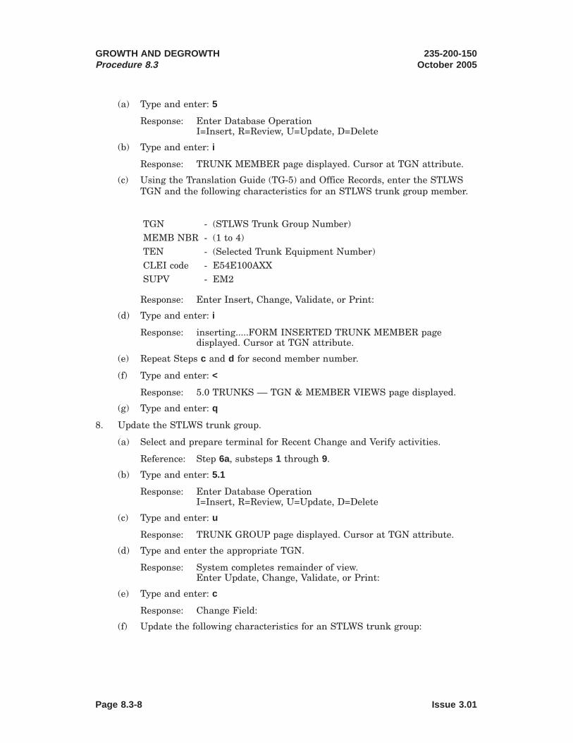
(a) Type and enter: 5
Response: Enter Database OperationI=Insert, R=Review, U=Update, D=Delete
(b) Type and enter: i
Response: TRUNK MEMBER page displayed. Cursor at TGN attribute.
(c) Using the Translation Guide (TG-5) and Office Records, enter the STLWSTGN and the following characteristics for an STLWS trunk group member.
TGN - (STLWS Trunk Group Number)MEMB NBR - (1 to 4)TEN - (Selected Trunk Equipment Number)CLEI code - E54E100AXXSUPV - EM2
Response: Enter Insert, Change, Validate, or Print:
(d) Type and enter: i
Response: inserting.....FORM INSERTED TRUNK MEMBER pagedisplayed. Cursor at TGN attribute.
(e) Repeat Steps c and d for second member number.
(f) Type and enter: <
Response: 5.0 TRUNKS –– TGN & MEMBER VIEWS page displayed.
(g) Type and enter: q
8. Update the STLWS trunk group.
(a) Select and prepare terminal for Recent Change and Verify activities.
Reference: Step 6a, substeps 1 through 9.
(b) Type and enter: 5.1
Response: Enter Database OperationI=Insert, R=Review, U=Update, D=Delete
(c) Type and enter: u
Response: TRUNK GROUP page displayed. Cursor at TGN attribute.
(d) Type and enter the appropriate TGN.
Response: System completes remainder of view.Enter Update, Change, Validate, or Print:
(e) Type and enter: c
Response: Change Field:
(f) Update the following characteristics for an STLWS trunk group:
GROWTH AND DEGROWTHProcedure 8.3
235-200-150October 2005
Page 8.3-8 Issue 3.01

TRK DIR - OUTGOTRK CLASS - LTPDCJCKRMK - DCJ FOR STLWS 1
Response: Enter Insert, Change, Validate, or Print:
(g) Type and enter: u
Response: updating.....FORM UPDATEDTRUNK GROUP page displayed.
(h) Type and enter: <
Response: 5.0 TRUNKS –– TGN & MEMBER VIEWS page displayed.
9. Update the STLWS trunk group members.
(a) Type and enter: 5
Response: Enter Database OperationI=Insert, R=Review, U=Update, D=Delete
(b) Type and enter: u
Response: TRUNK MEMBER page displayed. Cursor at TGN attribute.
(c) Input the appropriate TGN and MEMB NBR.
Response: System completes remainder of view.Enter Update, Change, Validate, or Print:
(d) Type and enter: c
Response: Change Field:
(e) Using the Translation Guide TG-5 and Office Records, update the followingcharacteristics for an STLWS trunk group member.
Response: Enter Insert, Change, Validate, or Print:
(f) Type and enter: u
Response: updating.....FORM UPDATEDTRUNK MEMBER page displayed. Cursor at TGN attribute.
(g) Repeat Steps c through f for second member number.
(h) Type and enter: <
Response: 5.0 TRUNKS –– TGN & MEMBER VIEWS page displayed.
(i) Type and enter: q
10. Restore the AC and DC jacks.
(a) At MCC, type and enter the following message:
RST:TRK,TKGMN= a-b,UCL:OOS,CADN ;RST:TRK,TKGMN= a-b,UCL:OOS,PPSRV ;
Where: a = trunk group
235-200-150October 2005
GROWTH AND DEGROWTHProcedure 8.3
Issue 3.01 Page 8.3-9
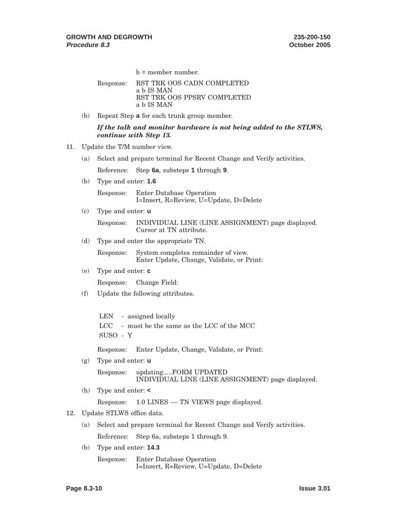
b = member number.
Response: RST TRK OOS CADN COMPLETEDa b IS MANRST TRK OOS PPSRV COMPLETEDa b IS MAN
(b) Repeat Step a for each trunk group member.
If the talk and monitor hardware is not being added to the STLWS,continue with Step 13.
11. Update the T/M number view.
(a) Select and prepare terminal for Recent Change and Verify activities.
Reference: Step 6a, substeps 1 through 9.
(b) Type and enter: 1.6
Response: Enter Database OperationI=Insert, R=Review, U=Update, D=Delete
(c) Type and enter: u
Response: INDIVIDUAL LINE (LINE ASSIGNMENT) page displayed.Cursor at TN attribute.
(d) Type and enter the appropriate TN.
Response: System completes remainder of view.Enter Update, Change, Validate, or Print:
(e) Type and enter: c
Response: Change Field:
(f) Update the following attributes.
LEN - assigned locallyLCC - must be the same as the LCC of the MCCSUSO - Y
Response: Enter Update, Change, Validate, or Print:
(g) Type and enter: u
Response: updating.....FORM UPDATEDINDIVIDUAL LINE (LINE ASSIGNMENT) page displayed.
(h) Type and enter: <
Response: 1.0 LINES –– TN VIEWS page displayed.
12. Update STLWS office data.
(a) Select and prepare terminal for Recent Change and Verify activities.
Reference: Step 6a, substeps 1 through 9.
(b) Type and enter: 14.3
Response: Enter Database OperationI=Insert, R=Review, U=Update, D=Delete
GROWTH AND DEGROWTHProcedure 8.3
235-200-150October 2005
Page 8.3-10 Issue 3.01

(c) Type and enter: u
Response: TRUNK LINE WORK STATION page displayed. Cursor atDEVICE ID attribute.
(d) Type and enter the appropriate DEVICE ID.
Response: System completes remainder of view.Enter Update, Change, Validate, or Print:
(e) Type and enter: c
Response: Change Field:
(f) Update this view as required.
Response: Enter Update, Change, Validate, or Print:
(g) Type and enter: u
Response: updating.....FORM UPDATEDTRUNK LINE WORK STATION page displayed.
(h) Type and enter: <
Response: 14.0 LINE & TRUNK TEST VIEWS page displayed.
13. Backup Incore ECD to disk.
(a) At MCC, do Steps b through i.
(b) Type and enter: 199
Response: RCV PARAMETER INFO page displayed with cursor at 1.database_name
(c) Type and enter: incore
Response: 2. review only
(d) Type and enter: n
Response: 3. journaling
(e) Type and enter: *
Response: UNIX RTR (ODIN) - Data Entry page displayed.
(f) Type and enter: activate
Response: activate form displayed with cursor at 1. copy_inc_to_disk:
(g) Type and enter: yes
Response: ODIN will request the action desired.
(h) Type and enter: e
Response: UNIX RTR (ODIN) - Data Entry page displayed.
(i) Type and enter: <
Response: RCV MENU RCV ECD COMPLETED
14. Backup Office Dependent Data.
Note: Prior to the response there will be completed responses for the switchingmodule and the AM.
235-200-150October 2005
GROWTH AND DEGROWTHProcedure 8.3
Issue 3.01 Page 8.3-11

(a) At MCC, type and enter: BKUP:ODD
Response: BKUP ODD COMPLETED
It is recommended that primary disk be backed up and that a shelf copy ofthe disks be made.
15. STOP. YOU HAVE COMPLETED THIS PROCEDURE.
GROWTH AND DEGROWTHProcedure 8.3
235-200-150October 2005
Page 8.3-12 Issue 3.01

8.4 Perform RC/V Terminal Growth
PROCEDURE
1. Enter UNIX1 RTR Recent Change and Verify.
(a) Is MCC or STLWS terminal to be used?
For MCC, proceed to Step b.
For STLWS proceed to Step i.
(b) At MCC, ensure terminal is in command mode.
(c) At MCC, do Steps d through h.
(d) Type and enter: 199
Response: RCV PARAMETER INFO page displayed with cursor at 1.database_name
(e) Type and enter: incore
Response: 2. review only
(f) Type and enter: n
Response: 3. journaling
(g) Type and enter: *
Response: RCV INITIALIZATION IN PROGRESS message displayed.UNIX RTR RCV (ODIN) - Data Entry page displayed.
(h) You have completed Enter UNIX RTR Recent Change and Verify, proceed toStep 2.
(i) At STLWS terminal, type and enter: RCV:MENU:DATA,RCVECD
Response: RCV ECD PARAMETER INFO page displayed with cursor at 1.database_name
(j) Type and enter: incore
Response: 2. review only
(k) Type and enter: n
Response: 3. journaling
(l) Type and enter: *
Response: RCV INITIALIZATION IN PROGRESS message displayed.UNIX RTR RCV (ODIN) - Data Entry page displayed. Cursorat Enter Form Name:
2. Enter high-level forms.
(a) Type and enter: toggle
Response: Will take you to the high-level forms.
3. Insert TTY data.
1. Registered trademark in the United States and other countries, licensed exclusively through X/OpenCompany, Limited.
235-200-150October 2005
GROWTH AND DEGROWTHProcedure 8.4
Issue 3.01 Page 8.4-1

Note: An ! may be entered any time prompted to abort the form and return tothe state when the form was started.
(a) Type and enter: ttyadd
Response: ttyadd form displayed. Cursor at 1.tty_name:
Note: An ! may be entered any time prompted to abort the form andreturn to the state when the form was started.
(b) Type and enter the following data:
1. tty_namea: enter TTY terminal name (TTY18, TTY19, orTTY21)
2. baud_rate: enter (as specified or CARRIAGE RETURN)3. login_term: enter (as specified or CARRIAGE RETURN)4. auth_chk: enter (as specified or CARRIAGE RETURN)5. term_type: enter (as specified or CARRIAGE RETURN)6. line_mode: enter (as specified or CARRIAGE RETURN)7. port: enter 2 or 3 for TTYC port (see Table 8.3-1 and
8.3-2)8. ttyc_number: enter TTYC number base on SAI port (see Table
8.3-1 and 8.3-2)9. plu_unit_name: enter CARRIAGE RETURN10. plu_unit_number: enter CARRIAGE RETURNNote(s):a. tty_name must be entered in all capital letters.
(c) Type and enter: i
Note: When growing a TTY terminal a defensive check failure messageREPT CONFIG FAULT Assert = 412 may be received. This failure messagemay be ignored.
4. Install the RC/V terminal to the SAI port corresponding to the TTYC port andTTYC number chosen in Table 8.3-1 and 8.3-2 (see Figure 8.4-1 , 8.4-2 and 8.4-3).
(a) Enter CARRIAGE RETURN
2. Trademark of Sun Microsystems, Inc.
GROWTH AND DEGROWTHProcedure 8.4
235-200-150October 2005
Page 8.4-2 Issue 3.01

PO RT 7
PO RT 0
PO RT 1
PO RT 2
PO RT 3
PO RT 4
PO RT 5
PO RT 6
Asynchr onousPatch Panel
SAI-1(O ptional )PO RT 7
PO RT 0
PO RT 1
PO RT 2
PO RT 3
PO RT 4
PO RT 5
PO RT 6
Asynchr onousPatch Panel
SAI-0
PCI1
PCI2
PCI3
PCI4
To RC/V
Figure 8.4-1 — Recent Change Terminal Installation ( Netra2 t 1120)
PORT 7
PORT 0
PORT 1
PORT 2
PORT 3
PORT 4
PORT 5
PORT 6
AsynchronousPatch Panel
SAI-1(Optional)
PORT 7
PORT 0
PORT 1
PORT 2
PORT 3
PORT 4
PORT 5
PORT 6
AsynchronousPatch Panel
SAI-0
To RC/V
Figure 8.4-2 — Recent Change Terminal Installation ( Netra 20)
235-200-150October 2005
GROWTH AND DEGROWTHProcedure 8.4
Issue 3.01 Page 8.4-3

5. Restore TTY x to service.
(a) At MCC, type and enter the appropriate message:
RST:TTY=x
Where: x = appropriate TTY number.
Response: RST TTY x COMPLETED
(b) Enter CARRIAGE RETURN
Response: FORM INSERTED
(c) Type and enter: <
Response: Exit the ttyadd form.
(d) Type and enter: <
Response: Exit this recent change session.
6. Backup Incore ECD to disk.
(a) At MCC, do Steps b through i.
(b) Type and enter: 199
Response: RCV PARAMETER INFO page displayed with cursor at 1.database_name
(c) Type and enter: incore
Response: 2. review only
Figure 8.4-3 — Recent Change Terminal Installation ( Netra 240)
GROWTH AND DEGROWTHProcedure 8.4
235-200-150October 2005
Page 8.4-4 Issue 3.01

(d) Type and enter: n
Response: 3. journaling
(e) Type and enter: *
Response: UNIX RTR (ODIN) - Data Entry page displayed.
(f) Type and enter: activate
Response: activate form displayed with cursor at 1. copy_inc_to_disk:
(g) Type and enter: yes
Response: ODIN will request the action desired.
(h) Type and enter: e
Response: ODIN returns to the UNIX RTR (ODIN) - Data Entry page.
(i) Type and enter: <
Response: RCV MENU RCV ECD COMPLETED
7. Change Security
(a) At MCC, type and enter message:
SET:RCACCESS,TTY=a,ACCESS=b
Where: a = ttys, ttyt, or ttyv
Where: ttys = TTY18ttyt = TTY19ttyv = TTY21
Where b is obtained from INPUT/OUTPUT Manual.
(b) To check on the access code, type and enter message:
OP:RCACCESS,TTY=a
Where: a = ttys, ttyt, or ttyv
Where: ttys = TTY18ttyt = TTY19ttyv = TTY21
Response: Access code returned in hexadecimal
8. Backup Office Dependent Data.
Note: Prior to the response there will be completed responses for the switchingmodule and the AM.
(a) At MCC, type and enter: BKUP:ODD
Response: BKUP ODD COMPLETED
It is recommended that primary disk be backed up and that a shelf copy ofthe disks be made.
9. STOP. YOU HAVE COMPLETED THIS PROCEDURE.
235-200-150October 2005
GROWTH AND DEGROWTHProcedure 8.4
Issue 3.01 Page 8.4-5


8.5 Grow MCC Dial-Up Modem Access
OVERVIEW
Through the use of commercially/Lucent available hardware, another option foraccessing the DRM’s MCC is over a dial-up modem connection.
Note: Transmitted and received data will be echoed on both the local (if equipped)and dial-up MCC (this configuration does not provide two separate independent MCCinterfaces to the DRM). As a result, care must be taken to ensure that two operatorsdo not try accessing the MCC at the same time.
Table 8.5-1 lists the required hardware for the dial-up MCC.
Table 8.5-1 — Dial-Up MCC Hardware Requirements
Item Lucent Comcode 3rd Party SourceSerial Splitter 407947290 Black Box Corp
TL073A-R2Modem Aa (localmodem)
106597768 Paradyne CorpModel 3810
Modem B (remotemodem)
106597768 Paradyne CorpModel 3810
orAny 9600 baud compatible modem
Cable 1 407645092 (10ft)or
407645118 (50ft)
Black Box Corp EYN251-0010-MM(10ft)
orEYN251-0050-MM (50ft)
Cable 2 407645092 (10ft)or
407645118 (50ft)
Black Box Corp EYN251-0010-MM(10ft)
orEYN251-0050-MM (50ft)
Cable 3b 407667351 (25ft)or
407667369 (50ft)or
407667377 (100ft)
Black Box Corp EDN16C-0025-MM(25ft)
orEDN16C-0050-MM (50ft)
orEDN16C-0100-MM (100ft)
Dial-Up MCCTerminal
407552488 (KS23996MCC), 408800027
(KS24697L1 MCC),or
PC running Lucent’sAIMS MCC terminal
emulator software
Any vt100 compatible terminalor
PC running a vt100 terminalemulator
Note(s):a. A generic 9600 baud modem is not recommended for the local modem.b. If Cable 3 is being connected to a PC running the Lucent AIMS MCC terminal
emulator software, a DB25 to DB9 connector adapter may also be requireddepending on the type of serial port equipped on the PC running the AIMSsoftware.
235-200-150October 2005
GROWTH AND DEGROWTHProcedure 8.5
Issue 3.00B Page 8.5-1

PROCEDURE
Warning: This growth procedure requires the workstation to be halted andpowered down. This procedure should be scheduled to ensure that it does notinterfere with any other planned maintenance activity.
1. Ensure that there is no Recent Change/Verify (RC/V) activity in progress.
2. Ensure that there is no SCANS session in progress.
3. Ensure that there is no AMA teleprocessing or tape writing sessions in progress.
4. Verify that all database updates have been written to disk.
(a) Enter the following input command on the MCC or a STLWS: BKUP:ODD;
Response: BKUP ODD COMPLETED
5. Write all AMA billing records from memory to disk.
(a) Type and enter command: WRT:AMADATA
Response: AMA DATA HAS BEEN WRITTEN TO DISKREADY TO TRANSFER DATA FROM DISK TOOUTPUT MEDIUM
6. Isolate the switching module from the AW.
(a) Go to the Switching Module Inhibit and Recovery Control Page. Type andenter command: 1800
(b) Manually isolate the switching module. Type and enter: 403
Response: ISOLATE (Y/N)
(c) Type and enter: y
Response: SET ISOL SM=1 COMPLETED
7. Enter poke 59 on the MCC EAI page to halt the AM emulator.
Response: Terminate Emulator (Y/N)?
8. Type and enter: y
9. Switch to the Sun1 UNIX2 Console of the AW by holding down the Ctrl key andpressing the Enter key on the MCC’s numeric keypad.
10. If a login prompt does not appear, press Return repeatedly until one appears.
11. At the login prompt, type and enter: awadmin
12. From the Administrative Workstation Main Menu, select the "Halt theWorkstation" option. Answer yes to the confirmation. If you select a task bymistake, answer no to the confirmation and the main menu will appear.
Response:You have chosen to halt the workstation. If the emulator is running,it must be halted before continuing. Refer to the main menu item ofHalt the Emulator.
1. Registered trademark of Sun Microsystems, Inc.2. Registered trademark in the United States and other countries, licensed exclusively through X/Open
Company, Limited.
GROWTH AND DEGROWTHProcedure 8.5
235-200-150October 2005
Page 8.5-2 Issue 3.00B

Do you want to continue (yes/no): yes
13. Wait for the ok prompt to appear.
14. Power down the AW units and MCC terminal in the following order:
For a Netra3 t 1120 or Netra 20 workstation:
1. Netra t 1120 and Netra 20 workstation. See "Remove Power toAdministrative Workstation (Netra t 1120 and Netra 20)", Procedure 4.7.
2. MCC terminal
For a Netra 240 workstation:
1. Netra 240 workstation and external tape device. See "Remove Power toAdministrative Workstation Units (Netra 240)", Procedure 4.9.
2. MCC terminal
15. Connect the dial-up MCC hardware as shown in Figure 8.5-1. Refer to Table8.5-1 for cable designations.
3. Trademark of Sun Microsystems, Inc.
235-200-150October 2005
GROWTH AND DEGROWTHProcedure 8.5
Issue 3.00B Page 8.5-3
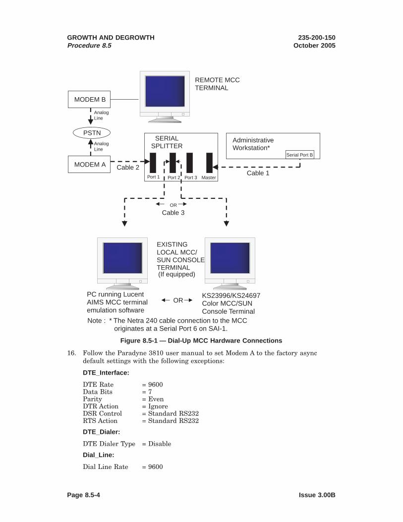
16. Follow the Paradyne 3810 user manual to set Modem A to the factory asyncdefault settings with the following exceptions:
DTE_Interface:
DTE Rate = 9600Data Bits = 7Parity = EvenDTR Action = IgnoreDSR Control = Standard RS232RTS Action = Standard RS232
DTE_Dialer:
DTE Dialer Type = Disable
Dial_Line:
Dial Line Rate = 9600
MODEM A
MODEM B
PSTN
AnalogLine
AnalogLine
REMOTE MCCTERMINAL
EXISTINGLOCAL MCC/SUN CONSOLETERMINAL(If equipped)
KS23996/KS24697Color MCC/SUNConsole Terminal
OR
AdministrativeWorkstation*
Serial Port B
SERIALSPLITTER
Port 1 Port 2 Port 3 MasterCable 1
Cable 2
Cable 3OR
PC running LucentAIMS MCC terminalemulation software
Note : * The Netra 240 cable connection to the MCCoriginates at a Serial Port 6 on SAI-1.
Figure 8.5-1 — Dial-Up MCC Hardware Connections
GROWTH AND DEGROWTHProcedure 8.5
235-200-150October 2005
Page 8.5-4 Issue 3.00B

V42/MNP/Buffer:
V42bic Compress = DisableMNP5 Compress = DisableFlw Cntl of DTE = XON/XOFFFlw Cntl 0f Modem
= XON/XOFF
Security:
IMPORTANT: To prevent unauthorized access to the DRM’s MCC, set per localguidelines.
17. If Modem B is a Paradyne 3810 modem, set the modem options on Modem B tothe same values as Modem A with the exception of the "DTE Dialer Type" field inthe "DTE_Dialer" submenu. For Modem B, "DTE Dialer Type" should be set toEnable. If Modem B is not a Paradyne 3810 modem, follow the user manualprovided with the modem to provision it so that its communication parameters(primarily the baud rate, parity, stop bits, and data bits) match that of Modem A.
18. Follow the user manual provided with the dial-up MCC terminal or terminalemulator software package to set the communication parameters on the dial-upMCC terminal to match those of the modems (for example, 9600 baud, 7 databits, 1 stop bit, Even parity).
19. Power up the AW units and dial-up MCC hardware in the following order:
For a Netra t 1120 or Netra 20 workstation:
1. MCC terminal
2. Modem A (Paradyne 3810)
3. Netra t 1120 and Netra 20 workstation. See "Restore Power toAdministrative Workstation (Netra t 1120 and Netra 20)", Procedure 4.8.
For a Netra 240 workstation:
1. MCC terminal
2. Modem A (Paradyne 3810)
3. Netra 240 workstation and external tape device. See "Restore Power toAdministrative Workstation Units (Netra 240)", Procedure 4.10.
20. Verify that the local MCC terminal is functional.
21. Verify that the dial-up MCC can be accessed.
a. Power up the dial-up MCC terminal and Modem B.
b. If the security options have not been set up on Modem A, type and enter:ATDTxxxyyyy at the dial-up MCC terminal.
where xxxyyyy = the phone number of the analog line connected to ModemA.
If the security options are set up on Modem A to require a password forconnection, type and enter: ATDTxxxyyyyWaaaaaaaa#
where: xxxyyyy = the phone number of the analog line to Modem A, and
aaaaaaaa = the 8 digit numeric password.
235-200-150October 2005
GROWTH AND DEGROWTHProcedure 8.5
Issue 3.00B Page 8.5-5

c. Wait for Modem A to be dialed and then verify that the MCC pages can beaccessed once the modem connection is established.
d. Drop the dial-up MCC connection. Type and enter: +++ at the dial-up MCCterminal to enter the modem’s online command mode. Then, type and enter:ATH0 to drop the connection.
22. STOP. YOU HAVE COMPLETED THIS PROCEDURE.
GROWTH AND DEGROWTHProcedure 8.5
235-200-150October 2005
Page 8.5-6 Issue 3.00B

8.6 Grow Remote Sun1 Console Dial-Up Modem Access
OVERVIEW
Through the use of commercially/Lucent available hardware, another option foraccessing the DRM’s Sun console is over a dial-up modem connection.
Note: Transmitted and received data will be echoed on both the local (if equipped)and dial-up Sun console (this configuration does not provide two separate independentSun console interfaces to the DRM). As a result, care must be taken to ensure thattwo operators do not try accessing the Sun console at the same time.
Table 8.6-1 lists the required hardware for the dial-up Sun console.
Table 8.6-1 — Dial-Up Sun Console Hardware Requirements
Item Lucent Comcode 3rd Party SourceSerial Splitter 407947290 Black Box Corp
TL073A-R2Modem Aa (localmodem)
106597768 Paradyne CorpModel 3810
Modem B (remotemodem)
106597768 Paradyne CorpModel 3810
orAny 9600 baud compatible modem
Cable 1 407645092 (10ft)or
407645118 (50ft)
Black Box Corp EYN251-0010-MM(10ft)
orEYN251-0050-MM (50ft)
Cable 2 407645092 (10ft)or
407645118 (50ft)
Black Box Corp EYN251-0010-MM(10ft)
orEYN251-0050-MM (50ft)
Cable 3b 407667351 (25ft)or
407667369 (50ft)or
407667377 (100ft)
Black Box Corp EDN16C-0025-MM(25ft)
orEDN16C-0050-MM (50ft)
orEDN16C-0100-MM (100ft)
Cable 4 407947340 (50ft) Black Box Corp EVNLS03–0050(50ft)
orStandard CAT5 RJ45 cable
Cable Adapter (RJ45female to DB25 malestraight-throughconnector)
403602717 Northern Technologies FM-010
1. Registered trademark of Sun Microsystems, Inc.
235-200-150October 2005
GROWTH AND DEGROWTHProcedure 8.6
See note(s) at end of table.
Issue 3.00B Page 8.6-1

Table 8.6-1 — Dial-Up Sun Console Hardware Requirements (Contd)
Item Lucent Comcode 3rd Party SourceDial-Up Sun ConsoleTerminal
407552488 (KS23996MCC), 408800027(KS24697L1 MCC)
orPC running Lucent’s
AIMS terminalemulator software
Any vt100 compatible terminalc
orPC running a vt100 terminal
emulator
Note(s):a. A generic 9600 baud modem is not recommended for the local modem.b. If a PC running the Lucent AIMS terminal emulator software is being used as the
local Sun console terminal, a DB25 to DB9 connector adapter may also berequired depending on the type of serial port equipped on the PC running theAIMS software. Cable 4 and the cable adapter are not needed when connecting toa local PC running AIMS. Refer to Figure 8.6-1 for more information.
c. Not supported by Lucent Technologies
PROCEDURE
Warning: This growth procedure requires the workstation to be halted andpowered down. This procedure should be scheduled to ensure that it does notinterfere with any other planned maintenance activity.
1. Ensure that there is no Recent Change/Verify (RC/V) activity in progress.
2. Ensure that there is no SCANS session in progress.
3. Ensure that there is no AMA teleprocessing or tape writing sessions in progress.
4. Verify that all database updates have been written to disk.
(a) Enter the following input command on the MCC or a STLWS: BKUP:ODD;
Response: BKUP ODD COMPLETED
5. Write all AMA billing records from memory to disk.
(a) Type and enter command: WRT:AMADATA
Response: AMA DATA HAS BEEN WRITTEN TO DISKREADY TO TRANSFER DATA FROM DISK TOOUTPUT MEDIUM
6. Isolate the switching module from the AW.
(a) Go to the Switching Module Inhibit and Recovery Control Page. Type andenter command: 1800
(b) Manually isolate the switching module. Type and enter: 403
Response: ISOLATE (Y/N)
(c) Type and enter: Y
Response: SET ISOL SM=1 COMPLETED
GROWTH AND DEGROWTHProcedure 8.6
235-200-150October 2005
Page 8.6-2 Issue 3.00B

7. Enter poke 59 on the MCC EAI page to halt the AM emulator.
Response: Terminate Emulator (Y/N)?
8. Type and enter: y
9. Switch to the Sun UNIX2 Console of the AW by holding down the Ctrl key andpressing the Enter key on the MCC’s numeric keypad.
10. If a login prompt does not appear, press Return repeatedly until one appears.
11. At the login prompt, type and enter: awadmin
12. From the Administrative Workstation Main Menu, select the "Halt theWorkstation" option. Answer yes to the confirmation. If you select a task bymistake, answer no to the confirmation and the main menu will appear.
Response:You have chosen to halt the workstation. If the emulator is running,it must be halted before continuing. Refer to the main menu item ofHalt the Emulator.
Do you want to continue (yes/no): yes
13. Wait for the ok prompt to appear.
14. Power down the AW units and Sun console terminal in the following order:
For a Netra3 t 1120 or Netra 20 workstation:
1. Netra t 1120 and Netra 20 workstation. See "Remove Power toAdministrative Workstation (Netra t 1120 and Netra 20)", Procedure 4.7.
2. Sun console terminal
For a Netra 240 workstation:
1. Netra 240 workstation and external tape device. See "Remove Power toAdministrative Workstation Units (Netra 240)", Procedure 4.9.
2. Sun console terminal
15. Connect the dial-up Sun console hardware as shown in Figure 8.6-1. Refer toTable 8.6-1 for cable designations.
2. Registered trademark in the United States and other countries, licensed exclusively through X/OpenCompany, Limited.
3. Trademark of Sun Microsystems, Inc.
235-200-150October 2005
GROWTH AND DEGROWTHProcedure 8.6
Issue 3.00B Page 8.6-3

16. Follow the Paradyne 3810 user manual and set the modem options on Modem Ato the factory async default settings with the following exceptions:
DTE_Interface:
DTE Rate = 9600Data Bits = 8Parity = NoneDTR Action = IgnoreDSR Control = Standard RS232RTS Action = Standard RS232
DTE_Dialer:
DTE Dialer Type = Disable
Dial_Line:
Dial Line Rate = 9600
V42/MNP/Buffer:
V42bic Compress = DisableMNP5 Compress = DisableFlw Cntl of DTE = XON/XOFFFlw Cntl 0f Modem
= XON/XOFF
Security:
MODEM A
MODEM B
PSTN
AnalogLine
AnalogLine
REMOTE SUNCONSOLETERMINAL
EXISTINGLOCAL MCC/SUN CONSOLETERMINAL(If equipped)
KS23996/KS24697Color MCC/SUNConsole Terminal
OR
AdministrativeWorkstation*
Serial Port A
SERIALSPLITTER
Port 1 Port 2 Port 3 MasterCable 1
Cable 2
Cable 3
PC running LucentAIMS MCC terminalemulation software
To AUX port
Cable Adapter
Cable 4
Note : * The Netra 240 cable connection to the SunConsole originates at a single DB-9 serial port.
Figure 8.6-1 — Dial-Up Sun Console Hardware Connections
GROWTH AND DEGROWTHProcedure 8.6
235-200-150October 2005
Page 8.6-4 Issue 3.00B

IMPORTANT: To prevent unauthorized access to the DRM’s Sun console, setper local guidelines.
17. If Modem B is a Paradyne 3810 modem, set the modem options on Modem B tothe same values as Modem A with the exception of the "DTE Dialer Type" field inthe "DTE_Dialer" submenu. For Modem B, "DTE Dialer Type" should be set toEnable. If Modem B is not a Paradyne 3810 modem, follow the user manualprovided with the modem to provision it so that its communication parameters(primarily the baud rate, parity, stop bits, and data bits) match that of Modem A.
18. Follow the user manual provided with the dial-up Sun console terminal orterminal emulator software package to set the communication parameters on thedial-up Sun console terminal to match those of the modems (for example, 9600baud, 8 data bits, 1 stop bit, No parity).
19. Power up the AW units and dial-up Sun console hardware in the following order:
For a Netra t 1120 or Netra 20 workstation:
1. Local MCC/Sun console terminal
2. Modem A (Paradyne 3810)
3. Netra t 1120 and Netra 20 workstation. See "Restore Power toAdministrative Workstation (Netra t 1120 and Netra 20)", Procedure 4.8.
For a Netra 240 workstation:
1. Local MCC/Sun console terminal
2. Modem A (Paradyne 3810)
3. Netra 240 workstation and external tape device. See "Restore Power toAdministrative Workstation Units (Netra 240)", Procedure 4.10.
20. Verify that the local Sun console terminal is functional.
21. Verify that the Sun console can be accessed via the modem.
a. Power up the dial-up Sun console terminal and Modem B.
b. If the security options have not been set up on Modem A, type and enter:ATDTxxxyyyy at the dial-up Sun console terminal.
where xxxyyyy = the phone number of the analog line connected to ModemA.
If the security options are set up on Modem A to require a password forconnection, type and enter: ATDTxxxyyyyWaaaaaaaa#
where: xxxyyyy = the phone number of the analog line to Modem A, and
aaaaaaaa = the 8 digit numeric password.
c. Wait for Modem A to be dialed and then verify that the Sun console pagescan be accessed once the modem connection is established.
235-200-150October 2005
GROWTH AND DEGROWTHProcedure 8.6
Issue 3.00B Page 8.6-5

Warning: Do not hit the break key on the dial-up Sun consoleterminal. Sending a break on the DRM’s Sun console port will causethe Sun workstation to halt. If a break is inadvertently sent, an okprompt will be displayed on the Sun console. Simply type and enter goat the ok prompt to allow the administrative workstation to resumeoperation.
d. Drop the dial-up Sun console connection. Type and enter: +++ at the dial-upSun console terminal to enter the modem’s online command mode. Then,type and enter: ATH0 to drop the connection.
22. STOP. YOU HAVE COMPLETED THIS PROCEDURE.
GROWTH AND DEGROWTHProcedure 8.6
235-200-150October 2005
Page 8.6-6 Issue 3.00B

8.7 Perform SCANS Data Link Growth
PROCEDURE
1. Enter UNIX1 RTR Recent Change and Verify.
(a) Is MCC or STLWS terminal to be used?
For MCC, proceed to Step b.For STLWS proceed to Step i.
(b) At MCC, ensure terminal is in command mode.
(c) At MCC, do Steps d through h.
(d) Type and enter: 199
Response: RCV PARAMETER INFO page displayed with cursor at 1.database_name
(e) Type and enter: incore
Response: 2. review only
(f) Type and enter: n
Response: 3. journaling
(g) Type and enter: *
Response: RCV INITIALIZATION IN PROGRESS message displayed.UNIX RTR RCV (ODIN) - Data Entry page displayed.
(h) You have completed Enter UNIX RTR Recent Change and Verify, proceed toStep 2.
(i) At STLWS terminal, type and enter: RCV:MENU:DATA,RCVECD
Response: RCV ECD PARAMETER INFO page displayed with cursor at 1.database_name
(j) Type and enter: incore
Response: 2. review only
(k) Type and enter: n
Response: 3. journaling
(l) Type and enter: *
Response: RCV INITIALIZATION IN PROGRESS message displayed.UNIX RTR RCV (ODIN) - Data Entry page displayed.
2. Enter high-level forms.
(a) Type and enter: toggle
Response: Will take you to the high-level forms.
3. Insert SDL data.
1. Registered trademark in the United States and other countries, licensed exclusively through X/OpenCompany, Limited.
235-200-150October 2005
GROWTH AND DEGROWTHProcedure 8.7
Issue 3.00B Page 8.7-1

Note: An ! may be entered any time prompted to abort the form and return tothe state when the form was started.
Note: Fields not specified receive the default value by entering CARRIAGERETURN.
(a) Type and enter: sdladd
Response: ttyadd form displayed. Cursor at 1. sdl_name:
(b) Type and enter the following data:
1. sdl_name: enter SDL02. port: enter 03. SCANS_baud_rate: enter CARRIAGE RETURN
(c) Type and enter: i
(d) The low-level forms will now be added automatically.
4. Install the SCANS data link. (See Figures 8.7-1 , 8.7-2 and 8.7-3 for hardwareconnection information.)
(a) Enter CARRIAGE RETURN
2. Trademark of Sun Microsystems, Inc.
PCI1
PCI2
PCI3
PCI4
01
2 3
Interface Conver ter
M odem /DCE
M odem /DCE
To SCANS
H S I
Figure 8.7-1 — SCANS Data Link Hardware Installation ( Netra2 t 1120)
GROWTH AND DEGROWTHProcedure 8.7
235-200-150October 2005
Page 8.7-2 Issue 3.00B

1
To SCANS
To SCCS
H S I
To Optional OSS
To AMA
321
Modem/DCE
Modem/DCE
Modem/DCE
M odem /DCE
Modem/DCE
Interface Converter
0
Figure 8.7-2 — SCANS Data Link Hardware Installation ( Netra 20)
235-200-150October 2005
GROWTH AND DEGROWTHProcedure 8.7
Issue 3.00B Page 8.7-3

5. Restore SDL0 to service.
(a) At MCC, type and enter the appropriate message:
RST:SDL=0
Response: RST SDL0 COMPLETED
(b) Enter CARRIAGE RETURN
Response: FORM INSERTED
(c) Type and enter: <
Response: Exit the sdladd form.
(d) Type and enter: <
Response: Exit this recent change session.
6. Backup Incore ECD to disk.
(a) At MCC, do Steps b through i.
Figure 8.7-3 — SCANS Data Link Hardware Installation ( Netra 240)
GROWTH AND DEGROWTHProcedure 8.7
235-200-150October 2005
Page 8.7-4 Issue 3.00B

(b) Type and enter: 199
Response: RCV PARAMETER INFO page displayed with cursor at 1.database_name
(c) Type and enter: incore
Response: 2. review only
(d) Type and enter: n
Response: 3. journaling
(e) Type and enter: *
Response: UNIX RTR (ODIN) - Data Entry page displayed.
(f) Type and enter: activate
Response: activate form displayed with cursor at 1. copy_inc_to_disk:
(g) Type and enter: y
Response: ODIN will request the action desired.
(h) Type and enter: e
Response: ODIN will return to the UNIX RTR (ODIN) - Data Entry page.
(i) Type and enter: <
Response: RCV MENU RCV ECD COMPLETED
7. Backup Office Dependent Data.
Note: Prior to the response there will be completed responses for the switchingmodule and the AM.
(a) At MCC, type and enter: BKUP:ODD
Response: BKUP ODD COMPLETED
It is recommended that primary disk be backed up and that a shelf copy ofthe disks be made.
8. Go to MCC display page 113 and verify that the data link shows up there.
9. STOP. YOU HAVE COMPLETED THIS PROCEDURE.
235-200-150October 2005
GROWTH AND DEGROWTHProcedure 8.7
Issue 3.00B Page 8.7-5


8.8 Perform AMA Data Link Growth
OVERVIEW
The AMA data link provides the hardware interface for the BILLDATS1 software usedto transmit AMA data to a host collector.
PROCEDURE
1. Enter UNIX2 RTR Recent Change and Verify.
(a) Is MCC or STLWS terminal to be used?
For MCC, proceed to Step b.For STLWS proceed to Step i.
(b) At MCC, ensure terminal is in command mode.
(c) At MCC, do Steps d through h.
(d) Type and enter: 199
Response: RCV PARAMETER INFO page displayed with cursor at 1.database_name
(e) Type and enter: incore
Response: 2. review only
(f) Type and enter: n
Response: 3. journaling
(g) Type and enter: *
Response: RCV INITIALIZATION IN PROGRESS message displayed.UNIX RTR RCV (ODIN) - Data Entry page displayed.
(h) You have completed Enter UNIX RTR Recent Change and Verify, proceed toStep 2.
(i) At STLWS terminal, type and enter: RCV:MENU:DATA,RCVECD
Response: RCV ECD PARAMETER INFO page displayed with cursor at 1.database_name
(j) Type and enter: incore
Response: 2. review only
(k) Type and enter: n
Response: 3. journaling
(l) Type and enter: *
Response: RCV INITIALIZATION IN PROGRESS message displayed.UNIX RTR RCV (ODIN) - Data Entry page displayed.
2. Enter high-level forms.
1. Registered trademark of AT&T Corp.2. Registered trademark in the United States and other countries, licensed exclusively through X/Open
Company, Limited.
235-200-150October 2005
GROWTH AND DEGROWTHProcedure 8.8
Issue 3.00B Page 8.8-1

(a) Type and enter: toggle
Response: Will take you to the high-level forms.
3. Insert SDL data.
(a) Type and enter: sdladd
Response: ttyadd form displayed. Cursor at 1. sdl_name:
Note: An ! may be entered any time prompted to abort the form andreturn to the state when the form was started.
(b) Type and enter the following data:
1. sdl_name: enter SDL13.2. port: enter 13. AMA_baud_rate: enter one of the following:
4800DIAL9600DIAL9600PRI56000PRI56000SW
Note: Fields not specified receive the default value by enteringCARRIAGE RETURN.
(c) Type and enter: i
(d) The low-level forms will now be added automatically.
4. Install the AMA data link. The AMA data link consists of a modem and modemcable connected to the High Speed Bus controller interface. (Figures 8.8-1, 8.8-2and 8.8-3 provide an illustration of the hardware connections for the AMA datalink.)
(a) Enter CARRIAGE RETURN
3. Trademark of Sun Microsystems, Inc.
GROWTH AND DEGROWTHProcedure 8.8
235-200-150October 2005
Page 8.8-2 Issue 3.00B

PCI1
PCI2
PCI3
PCI4
01
2 3
Interface Conver ter
M odem /DCE
To AM A
H S I
Figure 8.8-1 — AMA Data Link Hardware Connection ( Netra3 t 1120)
01
M odem /DCE
Modem/DCE
To SCANS
To SCCS
H S I
To Optional OSS
To AMA
32
Modem/DCE
Modem/DCE
Interface Converter
1
Modem/DCE
Figure 8.8-2 — AMA Data Link Hardware Installation ( Netra 20)
235-200-150October 2005
GROWTH AND DEGROWTHProcedure 8.8
Issue 3.00B Page 8.8-3

5. Restore SDL13 to service.
(a) At MCC, type and enter the appropriate message:
RST:SDL=13
Response: RST SDL13 COMPLETED
(b) Enter CARRIAGE RETURN
Response: FORM INSERTED
(c) Type and enter: <
Response: Exit the sdladd form.
(d) Type and enter: <
Response: Exit this recent change session.
6. Backup Incore ECD to disk.
(a) At MCC, do Steps b through i.
Figure 8.8-3 — AMA Data Link Hardware Installation ( Netra 240)
GROWTH AND DEGROWTHProcedure 8.8
235-200-150October 2005
Page 8.8-4 Issue 3.00B

(b) Type and enter: 199
Response: RCV PARAMETER INFO page displayed with cursor at 1.database_name
(c) Type and enter: incore
Response: 2. review only
(d) Type and enter: n
Response: 3. journaling
(e) Type and enter: *
Response: UNIX RTR (ODIN) - Data Entry page displayed.
(f) Type and enter: activate
Response: activate form displayed with cursor at 1. copy_inc_to_disk:
(g) Type and enter: y
Response: ODIN will request the action desired.
(h) Type and enter: e
Response: ODIN will return to the UNIX RTR (ODIN) - Data Entry page.
(i) Type and enter: <
Response: RCV MENU RCV ECD COMPLETED
7. Backup Office Dependent Data.
Note: Prior to the response there will be completed responses for the switchingmodule and the AM.
a. At MCC, type and enter: BKUP:ODD
Response: BKUP ODD COMPLETED
It is recommended that primary disk be backed up and that a shelf copy of thedisks be made.
8. Go to MCC display page 113 and verify that the data link shows up there.
9. STOP. YOU HAVE COMPLETED THIS PROCEDURE.
235-200-150October 2005
GROWTH AND DEGROWTHProcedure 8.8
Issue 3.00B Page 8.8-5


8.9 Perform SCC Data Link Growth
PROCEDURE
8.9.1 Start 3BSCC Process if not Already Started
1. At the MCC keyboard, if the UNIX1 console is not displayed, hold down <ctrl>and press the Enter.
2. Log in to the UNIX console with the UNIX RTR login.
3. Enter ps —ef | grep 3bscc
Response: root XXXX XXXX 0 11:07:40 ?0:10 3bscc 2XXXX XXXX is the process number.
4. If you receive the response above, proceed to Procedure 8.9.2. If you don’t receivethe above response, continue with the next step.
5. Enter cd /opt/ATT3bem/var
Response: #
6. Enter pwd
Response: /opt/ATT3bem/var
7. Change the UNEQ to EQIP:
1. Enter vi em_scc
2. Enter w
3. Enter cw
4. Enter EQIP
5. Press the <Esc>
6. Enter :wq
8. Enter pg em_scc
Response: scc_link EQIP
9. Enter /etc/init.d/att3bem stop
Response: #
10. Enter /etc/init.d/att3bem start
Response: #
11. Enter ps —ef | grep 3bscc
Response: root XXXX XXXX 0 11:07:40 ? 0:10 3bscc 2XXXX XXXX is the process number.
12. STOP. YOU HAVE COMPLETED THIS PROCEDURE.
1. Trademark of SUN Microsystems, Inc.
235-200-150April 2004
GROWTH AND DEGROWTHProcedure 8.9
Issue 3.00G Page 8.9-1

8.9.2 SCC Data Link Growth
1. Type and enter: incore
Response: 2. review only
2. Type and enter: n
Response: 3. journaling
3. Type and enter: *
Response: Enter Form Name:
4. Type and enter: toggle
Response: Enter Form Name:High-level mode displayed.
5. Type and enter: sdladd
Response: 1. sdl_name
6. Type and enter: SCC or SDL1
Response: 2. port
7. Type and enter: 2
Response: 3. ama_baud_rate
8. Enter CARRIAGE RETURN
Note: This field does not apply for SDL1.
Response: Enter Insert, Change . . .
9. Type and enter: i
The low-level forms will now be added automatically.
Response: 1. sdl_name
10. Type and enter: <
Response: Enter Form Name:
11. Type and enter: <
Response: Exit this recent change session.
12. To verify SDL1 has been inserted, view the 113 page. SDL1 should appear on thispage.
Note 1: To save the incore ECD changes made in Steps 1 through 11, executeSteps 16 through 23, otherwise continue with Step 13.
Note 2: SCC must also be grown into the MIN ECD. Execute Steps 13 through15 to test the MIN ECD growth capability.
13. Type and enter: 199
Response: RCV PARAMETER INFO page displayed with cursor at 1.database_name
14. Type and enter: rootdmly
Response: 2. review only
GROWTH AND DEGROWTHProcedure 8.9
235-200-150April 2004
Page 8.9-2 Issue 3.00G

15. Repeat Steps 2 through 11.
16. Save Incore ECD changes to disk:
Type and enter: 199
Response: RCV PARAMETER INFO page displayed with cursor at 1.database_name
17. Type and enter: incore
Response: 2. review only
18. Type and enter: n
Response: 3. journaling
19. Type and enter: *
Response: Enter Form Name:
20. Type and enter: activate
Response: 1. copy_inc_to_disk:
21. Enter CARRIAGE RETURN
Response: Enter Execute, Change. . .
22. Type and enter: e
Response: Enter Form Name:
23. Type and enter: <
Response: Exit this recent change session.
(a) Install the SCC data link. The SCC data link consists of a dataset and cableconnected to the High Speed Bus controller interface. (Figures 8.9-1 , 8.9-2and 8.9-3 provide an illustration of the hardware connections for the SCCdata link.)
2. Trademark of Sun Microsystems, Inc.
235-200-150April 2004
GROWTH AND DEGROWTHProcedure 8.9
Issue 3.00G Page 8.9-3

PCI1
PCI2
PCI3
PCI4
01
2 3
Interface Conver ter
M odem /DCE
To SCCS
H S I
Figure 8.9-1 — SCC Data Link Hardware Connection ( Netra2 t 1120)
To SCANS
To SCCS
H S I
To Optional OSS
To AMA
31
Modem/DCE
Modem/DCE
M odem /DCE
Modem/DCE
012
Interface Converter
Modem/DCE
Figure 8.9-2 — SCC Data Link Hardware Connection ( Netra 20)
GROWTH AND DEGROWTHProcedure 8.9
235-200-150April 2004
Page 8.9-4 Issue 3.00G

24. Restore SDL1 to service:
At MCC, type and enter: RST:SDL=1
Response: RST SDL 1 COMPLETED
25. Restart ULARP processes:
At MCC, type and enter: INIT:ULARP
Response: INIT ULARP COMPLETED
26. STOP. YOU HAVE COMPLETED THIS PROCEDURE.
Figure 8.9-3 — SCC Data Link Hardware Connection ( Netra 240)
235-200-150April 2004
GROWTH AND DEGROWTHProcedure 8.9
Issue 3.00G Page 8.9-5


8.10 Perform ConnectVu (ATPRC) Data Link Growth
PROCEDURE
1. Type and enter: incore
Response: 2. review only
2. Type and enter: n
Response: 3. journaling
3. Type and enter: *
Response: Enter Form Name:
4. Type and enter: toggle
Response: Enter Form Name:High-level mode displayed.
5. Type and enter: sdladd
Response: 1. sdl_name
6. Type and enter: ATPRC or SDL6
Response: 2. port
7. Type and enter: 3
Response: 3. ama_baud_rate
8. Enter CARRIAGE RETURN.
Note: This field does not apply for SDL6.
Response: Enter Insert, Change . . .
9. Type and enter: i
The low-level forms will now be added automatically.
Response: 1. sdl_name
10. Type and enter: <
Response: Enter Form Name:
11. Type and enter: <
Response: Exit this recent change session.
12. To verify SDL6 has been inserted, view the 113 page. SDL6 should appear on thispage.
13. Save Incore ECD changes to disk:
Type and enter: 199
Response: RCV PARAMETER INFO page displayed with cursor at 1.database_name
14. Type and enter: incore
Response: 2. review only
235-200-150October 2005
GROWTH AND DEGROWTHProcedure 8.10
Issue 3.00B Page 8.10-1

15. Type and enter: n
Response: 3. journaling
16. Type and enter: *
Response: Enter Form Name:
17. Type and enter: activate
Response: 1. copy_inc_to_disk:
18. Enter CARRIAGE RETURN.
Response: Enter Execute, Change. . .
19. Type and enter: e
Response: Enter Form Name:
20. Type and enter: <
Response: Exit this recent change session.
(a) Install the ATPRC Data Link. The ATPRC Data Link consists of a datasetand cable connected to the High Speed Bus controller interface. (Figures8.10-1, 8.10-2 and 8.10-3 provide an illustration of the hardware connectioninformation for the ATPRC Data Link.)
1. Trademark of Sun Microsystems, Inc.
PCI1
PCI2
PCI3
PCI4
01
2 3
Interface Conver ter
M odem /DCE
To SCCS
H S I
Figure 8.10-1 — ATPRC Data Link Hardware Connection ( Netra1 t 1120)
GROWTH AND DEGROWTHProcedure 8.10
235-200-150October 2005
Page 8.10-2 Issue 3.00B

To SCANS
To SCCS
H S I
To Optional OSS
To AMA
31
Modem/DCE
Modem/DCE
M odem /DCE
Modem/DCE
012
Interface Converter
Modem/DCE
Figure 8.10-2 — ATPRC Data Link Hardware Connection ( Netra 20)
235-200-150October 2005
GROWTH AND DEGROWTHProcedure 8.10
Issue 3.00B Page 8.10-3

21. Restore SDL6 to service:
At MCC, type and enter: RST:SDL=6
Response: RST SDL 6 COMPLETED
22. Execute a 54 on the MCC EIA page to allow the Data Link to be restored to ACT
23. STOP. YOU HAVE COMPLETED THIS PROCEDURE.
Figure 8.10-3 — ATPRC Data Link Hardware Connection ( Netra 240)
GROWTH AND DEGROWTHProcedure 8.10
235-200-150October 2005
Page 8.10-4 Issue 3.00B

8.11 Perform TDMS/EADAS Data Link Growth
OVERVIEW
This procedure is used to grow in the Traffic Data Management System/Engineeringand Administrative Data Acquisition System (TDMS/EADAS) BX.25 data link usingECD low-level forms. The TDMS/EADAS data link supports Lucent’s TDMSoperations system that is used to collect traffic data from the switch.
This procedure assumes the TDMS/EADAS link is to be grown on port 3 of the DRM’shigh speed interface (HSI). This procedure also assumes that the SCANS link is onHSI port 0 and the AMA link is on HSI port 1. This procedure makes adjustmentsbased on whether the optional SCC data link is grown in on HSI port 2.
The following hardware must be on site:
• RS422 to RS232 converter (Black Box part # IC456A)
• RS422 cable (Black Box part # EDN37J-00XX-MM; where XX is the cable lengthin feet)
• RS232 cable (Black Box part # ECM25C-0010-MM)
This procedure takes approximately 2 to 3 hours to complete.
PROCEDURE
1. This process is a combination of procedures. Perform these procedures in theorder in which they are presented.
1. “Grow in TDMS/EADAS Data Link in ECD,” Procedure 8.11.1.
2. “Update RC/V 8.1 for TDMS/EADAS Data Link,” Procedure 8.11.2.
3. “Connect Hardware for TDMS/EADAS Data Link,” Procedure 8.11.3.
4. “Define TDMS/EADAS Port on TDMS System,” Procedure 8.11.4.
5. “Initialize TDMS/EADAS Processes,” Procedure 8.11.5.
6. “Restore TDMS/EADAS Data Link to Service,” Procedure 8.11.6.
7. “Verify Operation of TDMS/EADAS Data Link,” Procedure 8.11.7.
8. “Backup Office Dependent Data”, Procedure 8.11.8
235-200-150January 2003
GROWTH AND DEGROWTHProcedure 8.11
Issue 3.00 Page 8.11-1


12345678901234567890123456789012123456789012345678901234561234567890123456789012345678901212345678901234567890123456123456789012345678901234567890121234567890123456789012345612345678901234567890123456789012123456789012345678901234561234567890123456789012345678901212345678901234567890123456123456789012345678901234567890121234567890123456789012345612345678901234567890123456789012123456789012345678901234561234567890123456789012345678901212345678901234567890123456123456789012345678901234567890121234567890123456789012345612345678901234567890123456789012123456789012345678901234561234567890123456789012345678901212345678901234567890123456123456789012345678901234567890121234567890123456789012345612345678901234567890123456789012123456789012345678901234561234567890123456789012345678901212345678901234567890123456123456789012345678901234567890121234567890123456789012345612345678901234567890123456789012123456789012345678901234561234567890123456789012345678901212345678901234567890123456123456789012345678901234567890121234567890123456789012345612345678901234567890123456789012123456789012345678901234561234567890123456789012345678901212345678901234567890123456
8.11.1 Grow in TDMS/EADAS Data Link in ECD
OVERVIEW
Warning: ECD forms are case sensitive. Use capital letters where shown.
PROCEDURE
1. Grow in UCB for SDLC3
At MCC, type and enter: 199 to access ECD RC/V.
Response: RCV PARAMETER INFO page displayed with cursor at 1.database_name
2. Type and enter: incore
Response: 2. review only
3. Type and enter: n
Response: 3. journaling
4. Type and enter: *
Response: RCV INITIALIZATION IN PROGRESS message displayed. UNIXRTR RCV (ODIN) - Data Entry page displayed. Cursor at EnterForm Name:
5. Type and enter: trbegin
Response: Transaction Begin1.tr_name: TRBEGIN
6. Enter CARRIAGE RETURN
Response: Enter Execute, Change. . .
7. Type and enter: e
8. Type and enter: ucb
Response: Enter Database OperationI=Insert, R=Review, U=Update, D=Delete
9. Type and enter: i
10. Populate the fields of the UCB record according to the following UCB form:
ucb (1/4)Information About Each Physical Device (Recent Change and Verify)
1.k_complex_name:________ 2.k_complex_number:____
3.k_unit_name:SDLC 4.k_unit_number:3
ucb_type 5.essential:Never 6.top:n 7.unique_unit:y
8.pseudo_node:n 9.restorable:y 10.removable:y
11.device_port:EMUDL 12.device_type:SDLC
13.internal_device:3 14.plant:y
15.critical:y 16.portswitch:n 17.posswitch:
235-200-150January 2003
GROWTH AND DEGROWTHProcedure 8.11.1
Issue 3.00 Page 8.11.1-1
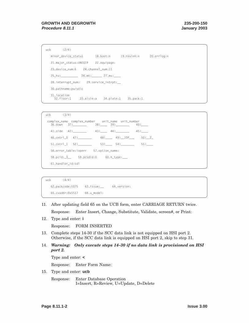
123456789012345678901234567890121234567890123456789012345612345678901234567890123456789012123456789012345678901234561234567890123456789012345678901212345678901234567890123456123456789012345678901234567890121234567890123456789012345612345678901234567890123456789012123456789012345678901234561234567890123456789012345678901212345678901234567890123456123456789012345678901234567890121234567890123456789012345612345678901234567890123456789012123456789012345678901234561234567890123456789012345678901212345678901234567890123456123456789012345678901234567890121234567890123456789012345612345678901234567890123456789012123456789012345678901234561234567890123456789012345678901212345678901234567890123456123456789012345678901234567890121234567890123456789012345612345678901234567890123456789012123456789012345678901234561234567890123456789012345678901212345678901234567890123456123456789012345678901234567890121234567890123456789012345612345678901234567890123456789012123456789012345678901234561234567890123456789012345678901212345678901234567890123456123456789012345678901234567890121234567890123456789012345612345678901234567890123456789012123456789012345678901234561234567890123456789012345678901212345678901234567890123456
12345678901234567890123456789012123456789012345678901234561234567890123456789012345678901212345678901234567890123456123456789012345678901234567890121234567890123456789012345612345678901234567890123456789012123456789012345678901234561234567890123456789012345678901212345678901234567890123456123456789012345678901234567890121234567890123456789012345612345678901234567890123456789012123456789012345678901234561234567890123456789012345678901212345678901234567890123456123456789012345678901234567890121234567890123456789012345612345678901234567890123456789012123456789012345678901234561234567890123456789012345678901212345678901234567890123456123456789012345678901234567890121234567890123456789012345612345678901234567890123456789012123456789012345678901234561234567890123456789012345678901212345678901234567890123456123456789012345678901234567890121234567890123456789012345612345678901234567890123456789012123456789012345678901234561234567890123456789012345678901212345678901234567890123456123456789012345678901234567890121234567890123456789012345612345678901234567890123456789012123456789012345678901234561234567890123456789012345678901212345678901234567890123456
12345678901234567890123456789012123456789012345678901234561234567890123456789012345678901212345678901234567890123456123456789012345678901234567890121234567890123456789012345612345678901234567890123456789012123456789012345678901234561234567890123456789012345678901212345678901234567890123456123456789012345678901234567890121234567890123456789012345612345678901234567890123456789012123456789012345678901234561234567890123456789012345678901212345678901234567890123456
ucb (2/4)
minor_device_status 18.boot:n 19.rexinh:n 20.errlog:n
21.major_status:UNEQIP 22.equipage:
23.device_num:6 24.channel_num:11
25.hv:__________ 26.mt:______ 27.mv:____
28.interrupt_num: 29.service_intrpt:__
30.pathname:pu/sdlc
31.location32.floor:1 33.aisle:a 34.plate:1 35.pack:1
ucb (3/4)
complex_name complex_number unit_name unit_number36.down 37)________ 38)____ 39)________ 40)____
41.side 42)________ 43)____ 44)________ 45)____
46.cntrl_0 47)________ 48)____ 49)__IOP___ 50)__2_
51.cntrl_1 52)________ 53)____ 54)________ 55)____
56.error_table:ioperr 57.option_name:
58.pcid:_3__ 59.pcsdid:0 60.h_type:___
61.handler_id:sdl
ucb (4/4)
62.packcode:t075 63.issue:__ 64.version:
65.cvaddr:0x5517 66.u_model:
11. After updating field 65 on the UCB form, enter CARRIAGE RETURN twice.
Response: Enter Insert, Change, Substitute, Validate, screen#, or Print:
12. Type and enter: i
Response: FORM INSERTED
13. Complete steps 14-30 if the SCC data link is not equipped on HSI port 2.Otherwise, if the SCC data link is equipped on HSI port 2, skip to step 31.
14. Warning: Only execute steps 14–30 if no data link is provisioned on HSIport 2.
Type and enter: <
Response: Enter Form Name:
15. Type and enter: ucb
Response: Enter Database OperationI=Insert, R=Review, U=Update, D=Delete
GROWTH AND DEGROWTHProcedure 8.11.1
235-200-150January 2003
Page 8.11.1-2 Issue 3.00
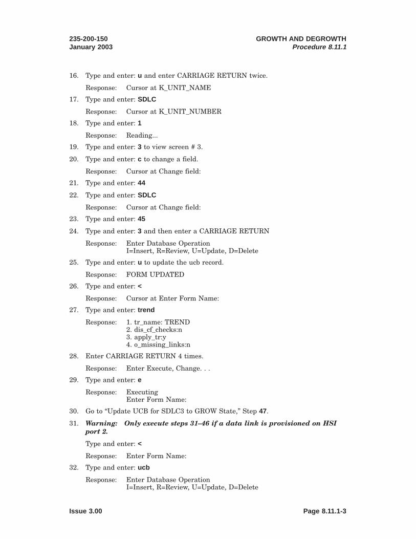
16. Type and enter: u and enter CARRIAGE RETURN twice.
Response: Cursor at K_UNIT_NAME
17. Type and enter: SDLC
Response: Cursor at K_UNIT_NUMBER
18. Type and enter: 1
Response: Reading...
19. Type and enter: 3 to view screen # 3.
20. Type and enter: c to change a field.
Response: Cursor at Change field:
21. Type and enter: 44
22. Type and enter: SDLC
Response: Cursor at Change field:
23. Type and enter: 45
24. Type and enter: 3 and then enter a CARRIAGE RETURN
Response: Enter Database OperationI=Insert, R=Review, U=Update, D=Delete
25. Type and enter: u to update the ucb record.
Response: FORM UPDATED
26. Type and enter: <
Response: Cursor at Enter Form Name:
27. Type and enter: trend
Response: 1. tr_name: TREND2. dis_cf_checks:n3. apply_tr:y4. o_missing_links:n
28. Enter CARRIAGE RETURN 4 times.
Response: Enter Execute, Change. . .
29. Type and enter: e
Response: ExecutingEnter Form Name:
30. Go to “Update UCB for SDLC3 to GROW State,” Step 47.
31. Warning: Only execute steps 31–46 if a data link is provisioned on HSIport 2.
Type and enter: <
Response: Enter Form Name:
32. Type and enter: ucb
Response: Enter Database OperationI=Insert, R=Review, U=Update, D=Delete
235-200-150January 2003
GROWTH AND DEGROWTHProcedure 8.11.1
Issue 3.00 Page 8.11.1-3

33. Type and enter: u and enter CARRIAGE RETURN twice.
Response: Cursor at K_UNIT_NAME
34. Type and enter: SDLC
Response: Cursor at K_UNIT_NUMBER
35. Type and enter: 2
Response: Reading...
36. Type and enter: 3 to view screen # 3.
37. Type and enter: c to change a field.
Response: Cursor at Change field:
38. Type and enter: 44
39. Type and enter: SDLC
Response: Cursor at Change field:
40. Type and enter: 45
41. Type and enter: 3 and then enter a CARRIAGE RETURN
Response: Enter Database OperationI=Insert, R=Review, U=Update, D=Delete
42. Type and enter: u to update the ucb record.
Response: FORM UPDATED.
43. Type and enter: <
Response: Cursor at Enter Form Name:
44. Type and enter: trend
Response: 1. tr_name: TREND2. dis_cf_checks:n3. apply_tr:y4. o_missing_links:n
45. Enter CARRIAGE RETURN 4 times.
Response: Enter Execute, Change. . .
46. Type and enter: e
Response: ExecutingEnter Form Name:
47. Update UCB for SDLC3 to GROW State
Type and enter: trbegin
Response: Transaction Begin1.tr_name: TRBEGIN
48. Enter CARRIAGE RETURN
Response: Enter Execute, Change. . .
49. Type and enter: e
GROWTH AND DEGROWTHProcedure 8.11.1
235-200-150January 2003
Page 8.11.1-4 Issue 3.00

50. Type and enter: ucb
Response: Enter Database OperationI=Insert, R=Review, U=Update, D=Delete
51. Type and enter: u and enter CARRIAGE RETURN twice.
Response: Cursor at K_UNIT_NAME
52. Type and enter: SDLC
Response: Cursor at K_UNIT_NUMBER
53. Type and enter: 3
Response: Reading...
54. Type and enter: 2 to view screen # 2.
55. Type and enter: c to change a field.
Response: Cursor at Change field:
56. Type and enter: 21 to change the MAJOR_STATUS field.
57. Type and enter: GROW and then enter CARRIAGE RETURN
Response: Enter Database OperationI=Insert, R=Review, U=Update, D=Delete
58. Type and enter: u to update the ucb record.
Response: FORM UPDATED.
59. Type and enter: <
Response: Cursor at Enter Form Name:
60. Type and enter: trend
Response: 1. tr_name: TREND2. dis_cf_checks:n3. apply_tr:y4. o_missing_links:n
61. Enter CARRIAGE RETURN 4 times.
Response: Enter Execute, Change. . .
62. Type and enter: e
Response: ExecutingEnter Form Name:
63. Insert UCB and CPBLX3 for SDL3 and Update SDLC3 to Down Reference Sidle
Type and enter: trbegin
Response: Transaction Begin1.tr_name: TRBEGIN
64. Enter CARRIAGE RETURN
Response: Enter Execute, Change. . .
65. Type and enter: e
235-200-150January 2003
GROWTH AND DEGROWTHProcedure 8.11.1
Issue 3.00 Page 8.11.1-5

12345678901234567890123456789012123456789012345678901234561234567890123456789012345678901212345678901234567890123456123456789012345678901234567890121234567890123456789012345612345678901234567890123456789012123456789012345678901234561234567890123456789012345678901212345678901234567890123456123456789012345678901234567890121234567890123456789012345612345678901234567890123456789012123456789012345678901234561234567890123456789012345678901212345678901234567890123456123456789012345678901234567890121234567890123456789012345612345678901234567890123456789012123456789012345678901234561234567890123456789012345678901212345678901234567890123456123456789012345678901234567890121234567890123456789012345612345678901234567890123456789012123456789012345678901234561234567890123456789012345678901212345678901234567890123456123456789012345678901234567890121234567890123456789012345612345678901234567890123456789012123456789012345678901234561234567890123456789012345678901212345678901234567890123456123456789012345678901234567890121234567890123456789012345612345678901234567890123456789012123456789012345678901234561234567890123456789012345678901212345678901234567890123456
12345678901234567890123456789012123456789012345678901234561234567890123456789012345678901212345678901234567890123456123456789012345678901234567890121234567890123456789012345612345678901234567890123456789012123456789012345678901234561234567890123456789012345678901212345678901234567890123456123456789012345678901234567890121234567890123456789012345612345678901234567890123456789012123456789012345678901234561234567890123456789012345678901212345678901234567890123456123456789012345678901234567890121234567890123456789012345612345678901234567890123456789012123456789012345678901234561234567890123456789012345678901212345678901234567890123456123456789012345678901234567890121234567890123456789012345612345678901234567890123456789012123456789012345678901234561234567890123456789012345678901212345678901234567890123456123456789012345678901234567890121234567890123456789012345612345678901234567890123456789012123456789012345678901234561234567890123456789012345678901212345678901234567890123456123456789012345678901234567890121234567890123456789012345612345678901234567890123456789012123456789012345678901234561234567890123456789012345678901212345678901234567890123456
123456789012345678901234567890121234567890123456789012345612345678901234567890123456789012123456789012345678901234561234567890123456789012345678901212345678901234567890123456123456789012345678901234567890121234567890123456789012345612345678901234567890123456789012123456789012345678901234561234567890123456789012345678901212345678901234567890123456123456789012345678901234567890121234567890123456789012345612345678901234567890123456789012123456789012345678901234561234567890123456789012345678901212345678901234567890123456123456789012345678901234567890121234567890123456789012345612345678901234567890123456789012123456789012345678901234561234567890123456789012345678901212345678901234567890123456123456789012345678901234567890121234567890123456789012345612345678901234567890123456789012123456789012345678901234561234567890123456789012345678901212345678901234567890123456123456789012345678901234567890121234567890123456789012345612345678901234567890123456789012123456789012345678901234561234567890123456789012345678901212345678901234567890123456123456789012345678901234567890121234567890123456789012345612345678901234567890123456789012123456789012345678901234561234567890123456789012345678901212345678901234567890123456
66. Type and enter: ucb
Response: Enter Database OperationI=Insert, R=Review, U=Update, D=Delete
67. Type and enter: i
68. Populate the fields of the UCB record according to the following UCB form:
ucb (1/4)Information About Each Physical Device (Recent Change and Verify)
1.k_complex_name:________ 2.k_complex_number:____
3.k_unit_name:SDL 4.k_unit_number:3
ucb_type 5.essential:NEVER 6.top:n 7.unique_unit:y
8.pseudo_node:n 9.restorable:y 10.removable:y
11.device_port:EMUDL 12.device_type:SDL
13.internal_device:2 14.plant:y
15.critical:y 16.portswitch:n 17.posswitch:
ucb (2/4)
minor_device_status 18.boot:n 19.rexinh:n 20.errlog:n
21.major_status:UNEQIP 22.equipage:
23.device_num:6 24.channel_num:11
25.hv:__________ 26.mt:______ 27.mv:____
28.interrupt_num: 29.service_intrpt:__
30.pathname:pu/sdl
31.location32.floor:1 33.aisle:a 34.plate:1 35.pack:1
ucb (3/4)
complex_name complex_number unit_name unit_number36.down 37)________ 38)____ 39)________ 40)____
41.side 42)________ 43)____ 44)________ 45)____
46.cntrl_0 47)________ 48)____ 49)_SDLC____ 50)_3__
51.cntrl_1 52)________ 53)____ 54)________ 55)____
56.error_table:ioperr 57.option_name:cpblx33
58.pcid:_3__ 59.pcsdid:2 60.h_type:___
61.handler_id:sdl
GROWTH AND DEGROWTHProcedure 8.11.1
235-200-150January 2003
Page 8.11.1-6 Issue 3.00

123456789012345678901234567890121234567890123456789012345612345678901234567890123456789012123456789012345678901234561234567890123456789012345678901212345678901234567890123456123456789012345678901234567890121234567890123456789012345612345678901234567890123456789012123456789012345678901234561234567890123456789012345678901212345678901234567890123456123456789012345678901234567890121234567890123456789012345612345678901234567890123456789012123456789012345678901234561234567890123456789012345678901212345678901234567890123456
1234567890123456789012345678901212345678901234567890123456123456789012345678901234567890121234567890123456789012345612345678901234567890123456789012123456789012345678901234561234567890123456789012345678901212345678901234567890123456123456789012345678901234567890121234567890123456789012345612345678901234567890123456789012123456789012345678901234561234567890123456789012345678901212345678901234567890123456123456789012345678901234567890121234567890123456789012345612345678901234567890123456789012123456789012345678901234561234567890123456789012345678901212345678901234567890123456123456789012345678901234567890121234567890123456789012345612345678901234567890123456789012123456789012345678901234561234567890123456789012345678901212345678901234567890123456123456789012345678901234567890121234567890123456789012345612345678901234567890123456789012123456789012345678901234561234567890123456789012345678901212345678901234567890123456123456789012345678901234567890121234567890123456789012345612345678901234567890123456789012123456789012345678901234561234567890123456789012345678901212345678901234567890123456123456789012345678901234567890121234567890123456789012345612345678901234567890123456789012123456789012345678901234561234567890123456789012345678901212345678901234567890123456
ucb (4/4)
62.packcode:____ 63.issue:__ 64.version:__
65.cvaddr:______ 66.u_model:
69. After updating field 59 on the UCB form, enter CARRIAGE RETURN or > untilthe following response is observed.
Response: Enter Insert, Change, Substitute, Validate, screen#, or Print:
70. Type and enter: i
Response: FORM INSERTED
71. Type and enter: <
Response: Enter Form Name:
72. Type and enter: cpblx3
Response: Enter Database OperationI=Insert, R=Review, U=Update, D=Delete
73. Type and enter: i
74. Populate the fields of the CPBLX3 record according to the following CPBLX3form.
Note 1: Field 2 (speed) should be set to the required baud rate of 110, 300,1200, 2400, 4800, 9600, 56000, or 64000.
Note 2: There is a version of this form, which does not display the CAUTIONat the top of the screen. As a result, the screen layout will differ slightly from thescreens shown in this step. Make sure that the correct fields are being updatedwith the data shown in this step.
cpblx3 (1/5)
Communications Protocol Option Block (Recent Change and Verify)
THESE ARE CRITICAL SYSTEM PARAMETERS!! CHANGE WITH EXTREME CAUTION.See Note 2
1.option_name:cpblx33
2.speed: "See Note 1″ 3.duplex:full 4.ds_type:2024A
5.carrier:c 6.line_access:private 7.mode_op:b
8.pdtime1:60 9.pdtime2:100 10.window:4
11.rexmit:7 12.dcedte:0 13.pcsd_stat:active
14.config:simplex
235-200-150January 2003
GROWTH AND DEGROWTHProcedure 8.11.1
Issue 3.00 Page 8.11.1-7

12345678901234567890123456789012123456789012345678901234561234567890123456789012345678901212345678901234567890123456123456789012345678901234567890121234567890123456789012345612345678901234567890123456789012123456789012345678901234561234567890123456789012345678901212345678901234567890123456123456789012345678901234567890121234567890123456789012345612345678901234567890123456789012123456789012345678901234561234567890123456789012345678901212345678901234567890123456123456789012345678901234567890121234567890123456789012345612345678901234567890123456789012123456789012345678901234561234567890123456789012345678901212345678901234567890123456123456789012345678901234567890121234567890123456789012345612345678901234567890123456789012123456789012345678901234561234567890123456789012345678901212345678901234567890123456123456789012345678901234567890121234567890123456789012345612345678901234567890123456789012123456789012345678901234561234567890123456789012345678901212345678901234567890123456
12345678901234567890123456789012123456789012345678901234561234567890123456789012345678901212345678901234567890123456123456789012345678901234567890121234567890123456789012345612345678901234567890123456789012123456789012345678901234561234567890123456789012345678901212345678901234567890123456123456789012345678901234567890121234567890123456789012345612345678901234567890123456789012123456789012345678901234561234567890123456789012345678901212345678901234567890123456123456789012345678901234567890121234567890123456789012345612345678901234567890123456789012123456789012345678901234561234567890123456789012345678901212345678901234567890123456123456789012345678901234567890121234567890123456789012345612345678901234567890123456789012123456789012345678901234561234567890123456789012345678901212345678901234567890123456123456789012345678901234567890121234567890123456789012345612345678901234567890123456789012123456789012345678901234561234567890123456789012345678901212345678901234567890123456
123456789012345678901234567890121234567890123456789012345612345678901234567890123456789012123456789012345678901234561234567890123456789012345678901212345678901234567890123456123456789012345678901234567890121234567890123456789012345612345678901234567890123456789012123456789012345678901234561234567890123456789012345678901212345678901234567890123456123456789012345678901234567890121234567890123456789012345612345678901234567890123456789012123456789012345678901234561234567890123456789012345678901212345678901234567890123456123456789012345678901234567890121234567890123456789012345612345678901234567890123456789012123456789012345678901234561234567890123456789012345678901212345678901234567890123456123456789012345678901234567890121234567890123456789012345612345678901234567890123456789012123456789012345678901234561234567890123456789012345678901212345678901234567890123456
1234567890123456789012345678901212345678901234567890123456123456789012345678901234567890121234567890123456789012345612345678901234567890123456789012123456789012345678901234561234567890123456789012345678901212345678901234567890123456123456789012345678901234567890121234567890123456789012345612345678901234567890123456789012123456789012345678901234561234567890123456789012345678901212345678901234567890123456123456789012345678901234567890121234567890123456789012345612345678901234567890123456789012123456789012345678901234561234567890123456789012345678901212345678901234567890123456123456789012345678901234567890121234567890123456789012345612345678901234567890123456789012123456789012345678901234561234567890123456789012345678901212345678901234567890123456123456789012345678901234567890121234567890123456789012345612345678901234567890123456789012123456789012345678901234561234567890123456789012345678901212345678901234567890123456123456789012345678901234567890121234567890123456789012345612345678901234567890123456789012123456789012345678901234561234567890123456789012345678901212345678901234567890123456
cpblx3 (2/5)
THESE ARE CRITICAL SYSTEM PARAMETERS!! CHANGE WITH EXTREME CAUTION.See Note 2
15.ldtel sid tlim telno1)______ ____ ______________2)______ ____ ______________3)______ ____ ______________4)______ ____ ______________
19.security:n 20.link_id:0
21.feid_len:0 22.neid_len:0 23.password_len:0
cpblx3 (3/5)
THESE ARE CRITICAL SYSTEM PARAMETERS!! CHANGE WITH EXTREME CAUTION.See Note 2
24.feid.fend1)____ 4)____ 7)____ 10)____ 13)____2)____ 5)____ 8)____ 11)____ 14)____3)____ 6)____ 9)____ 12)____ 15)____
35.neid.nend1)____ 4)____ 7)____ 10)____ 13)____2)____ 5)____ 8)____ 11)____ 14)____3)____ 6)____ 9)____ 12)____ 15)____
cpblx3 (4/5)
THESE ARE CRITICAL SYSTEM PARAMETERS!! CHANGE WITH EXTREME CAUTION.See Note 2
46.pswrd.pwrd1)____ 4)____ 7)____ 10)____ 13)____2)____ 5)____ 8)____ 11)____ 14)____3)____ 6)____ 9)____ 12)____ 15)____
57.perm_state:allow 58.outscrsiz:4062 59.outpktsiz:259 60.inscrsiz:406261.inpktsiz:259 62.hup:n 63.spckt:0 64.x3wsize:2 65.x3psize:256
cpblx3 (5/5)
THESE ARE CRITICAL SYSTEM PARAMETERS!! CHANGE WITH EXTREME CAUTION.See Note 2
66.x3pvcn.ldinno
1)_____ 6)_____ 11)_____ 16)_____ 21)_____ 26)_____ 31)_____2)1 7)_____ 12)_____ 17)_____ 22)_____ 27)_____ 32)_____3)3 8)_____ 13)_____ 18)_____ 23)_____ 28)_____4)2 9)_____ 14)_____ 19)_____ 24)_____ 29)_____5)_____ 10)_____ 15)_____ 20)_____ 25)_____ 30)_____
81.time_ti:180 82.time_tj:60 83.time_tf:60 84.time_tl:60
85.time_td:180 86.time_ts:180 87.time_ack:5
75. After updating field 87 on the UCB form, enter CARRIAGE RETURN
Response: Enter Insert, Change, Substitute, Validate, screen#, or Print:
76. Type and enter: i
Response: FORM INSERTED
GROWTH AND DEGROWTHProcedure 8.11.1
235-200-150January 2003
Page 8.11.1-8 Issue 3.00
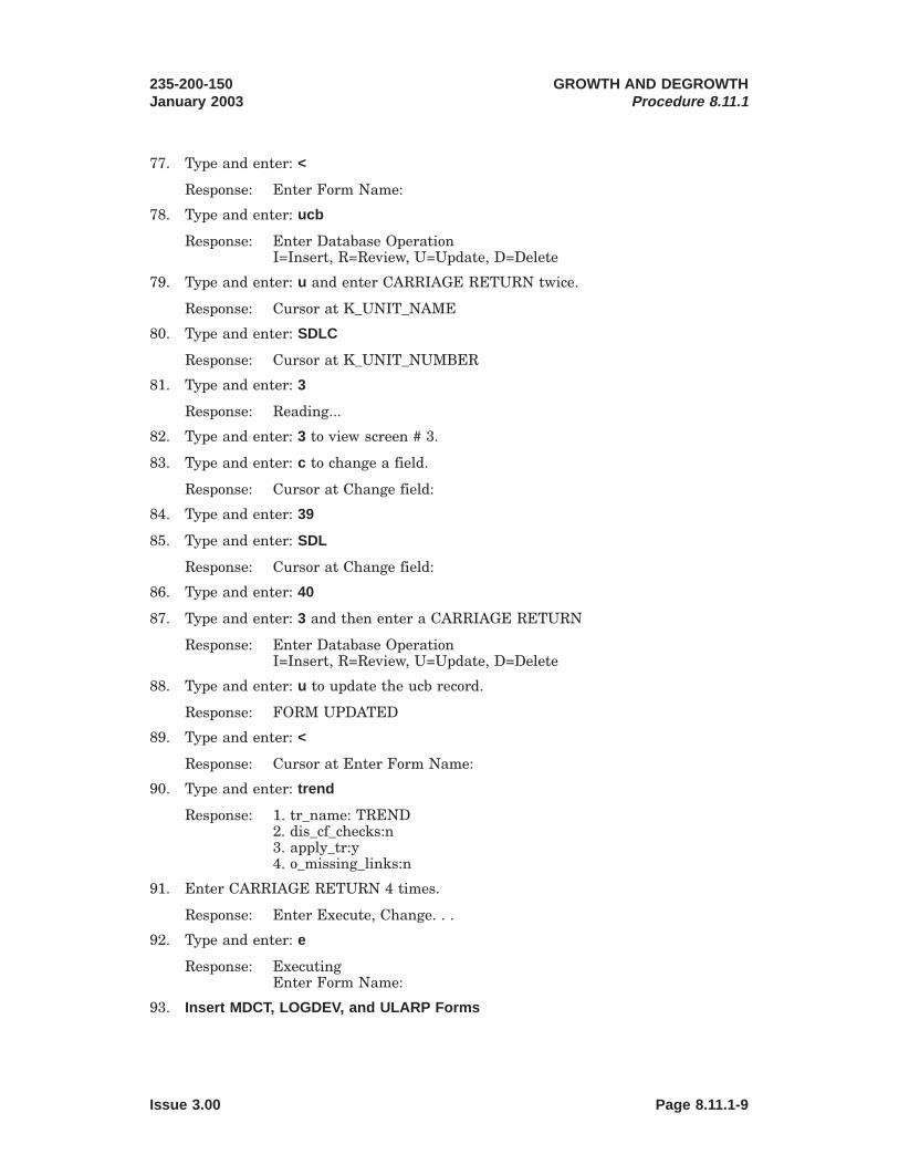
77. Type and enter: <
Response: Enter Form Name:
78. Type and enter: ucb
Response: Enter Database OperationI=Insert, R=Review, U=Update, D=Delete
79. Type and enter: u and enter CARRIAGE RETURN twice.
Response: Cursor at K_UNIT_NAME
80. Type and enter: SDLC
Response: Cursor at K_UNIT_NUMBER
81. Type and enter: 3
Response: Reading...
82. Type and enter: 3 to view screen # 3.
83. Type and enter: c to change a field.
Response: Cursor at Change field:
84. Type and enter: 39
85. Type and enter: SDL
Response: Cursor at Change field:
86. Type and enter: 40
87. Type and enter: 3 and then enter a CARRIAGE RETURN
Response: Enter Database OperationI=Insert, R=Review, U=Update, D=Delete
88. Type and enter: u to update the ucb record.
Response: FORM UPDATED
89. Type and enter: <
Response: Cursor at Enter Form Name:
90. Type and enter: trend
Response: 1. tr_name: TREND2. dis_cf_checks:n3. apply_tr:y4. o_missing_links:n
91. Enter CARRIAGE RETURN 4 times.
Response: Enter Execute, Change. . .
92. Type and enter: e
Response: ExecutingEnter Form Name:
93. Insert MDCT, LOGDEV, and ULARP Forms
235-200-150January 2003
GROWTH AND DEGROWTHProcedure 8.11.1
Issue 3.00 Page 8.11.1-9

12345678901234567890123456789012123456789012345678901234561234567890123456789012345678901212345678901234567890123456123456789012345678901234567890121234567890123456789012345612345678901234567890123456789012123456789012345678901234561234567890123456789012345678901212345678901234567890123456123456789012345678901234567890121234567890123456789012345612345678901234567890123456789012123456789012345678901234561234567890123456789012345678901212345678901234567890123456123456789012345678901234567890121234567890123456789012345612345678901234567890123456789012123456789012345678901234561234567890123456789012345678901212345678901234567890123456123456789012345678901234567890121234567890123456789012345612345678901234567890123456789012123456789012345678901234561234567890123456789012345678901212345678901234567890123456123456789012345678901234567890121234567890123456789012345612345678901234567890123456789012123456789012345678901234561234567890123456789012345678901212345678901234567890123456
1234567890123456789012345678901212345678901234567890123456123456789012345678901234567890121234567890123456789012345612345678901234567890123456789012123456789012345678901234561234567890123456789012345678901212345678901234567890123456123456789012345678901234567890121234567890123456789012345612345678901234567890123456789012123456789012345678901234561234567890123456789012345678901212345678901234567890123456123456789012345678901234567890121234567890123456789012345612345678901234567890123456789012123456789012345678901234561234567890123456789012345678901212345678901234567890123456123456789012345678901234567890121234567890123456789012345612345678901234567890123456789012123456789012345678901234561234567890123456789012345678901212345678901234567890123456123456789012345678901234567890121234567890123456789012345612345678901234567890123456789012123456789012345678901234561234567890123456789012345678901212345678901234567890123456123456789012345678901234567890121234567890123456789012345612345678901234567890123456789012123456789012345678901234561234567890123456789012345678901212345678901234567890123456
Type and enter: trbegin
Response: Transaction Begin1.tr_name: TRBEGIN
94. Enter CARRIAGE RETURN
Response: Enter Execute, Change. . .
95. Type and enter: e
Response: FORM EXECUTED
96. Type and enter: mdct
Response: Enter Database OperationI=Insert, R=Review, U=Update, D=Delete
97. Type and enter: i
98. Populate the fields of the MDCT record according to the following MDCT form.
Note: In the following form, Field 3 (mdct_type) is set to the lower case letter l,and Field 4 (mdct_id_char) is set to the number 1.
mdct (1/3)Logical To Physical Device Transaction (Recent Change and Verify)
1.mdct_name:EADAS 2.logical_device:io
3.mdct_type:l 4.mdct_id_char:1
5.active_devices6.complex_name 7.complex_number 8.unit_name 9.unit_number1)________ ____ SDL 32)________ ____ ________ ____3)________ ____ ________ ____4)________ ____ ________ ____
mdct (2/3)
10.backup_devices11.complex_name 12.complex_number 13.unit_name 14.unit_number1)________ ____ ________ ____2)________ ____ ________ ____3)________ ____ ________ ____4)________ ____ ________ ____
15.spare_devices16.complex_name 17.complex_number 18.unit_name 19.unit_number1)________ ____ ________ ____2)________ ____ ________ ____3)________ ____ ________ ____4)________ ____ ________ ____
GROWTH AND DEGROWTHProcedure 8.11.1
235-200-150January 2003
Page 8.11.1-10 Issue 3.00

12345678901234567890123456789012123456789012345678901234561234567890123456789012345678901212345678901234567890123456123456789012345678901234567890121234567890123456789012345612345678901234567890123456789012123456789012345678901234561234567890123456789012345678901212345678901234567890123456123456789012345678901234567890121234567890123456789012345612345678901234567890123456789012123456789012345678901234561234567890123456789012345678901212345678901234567890123456123456789012345678901234567890121234567890123456789012345612345678901234567890123456789012123456789012345678901234561234567890123456789012345678901212345678901234567890123456123456789012345678901234567890121234567890123456789012345612345678901234567890123456789012123456789012345678901234561234567890123456789012345678901212345678901234567890123456
123456789012345678901234567890121234567890123456789012345612345678901234567890123456789012123456789012345678901234561234567890123456789012345678901212345678901234567890123456123456789012345678901234567890121234567890123456789012345612345678901234567890123456789012123456789012345678901234561234567890123456789012345678901212345678901234567890123456123456789012345678901234567890121234567890123456789012345612345678901234567890123456789012123456789012345678901234561234567890123456789012345678901212345678901234567890123456123456789012345678901234567890121234567890123456789012345612345678901234567890123456789012123456789012345678901234561234567890123456789012345678901212345678901234567890123456123456789012345678901234567890121234567890123456789012345612345678901234567890123456789012123456789012345678901234561234567890123456789012345678901212345678901234567890123456
mdct (3/3)
20.oos_devices21.complex_name 22.complex_number 23.unit_name 24.unit_number1)________ ____ ________ ____2)________ ____ ________ ____3)________ ____ ________ ____4)________ ____ ________ ____
25.gettyid:getty0
99. After updating field 25 on the MDCT form, enter CARRIAGE RETURN
Response: Enter Insert, Change, Substitute, Validate, screen#, or Print:
100. Type and enter: i
Response: FORM INSERTED
101. Type and enter: <
Response: Enter Form Name:
102. Type and enter: logdev
Response: Enter Database OperationI=Insert, R=Review, U=Update, D=Delete
103. Type and enter: i
104. Populate the fields of the first LOGDEV record according to the followingLOGDEV form.
logdev (1/1)Logical Device Information (Recent Change and Verify)
1.logical_name:/dev/eadlo 2.partition:0x2
3.mdct_name:EADAS 4.channel_id:___
5.dcn:23 6.driver_type:c
7.gettyid:________ 8.usr:rw-
9.grp:rw- 10.other:---
105. After updating field 9 on the LOGDEV form, enter CARRIAGE RETURN untilthe following response is observed.
Response: Enter Insert, Change, Substitute, Validate, screen#, or Print:
106. Type and enter: i
Response: FORM INSERTED
107. Populate the fields of the second LOGDEV record according to the followingLOGDEV form.
235-200-150January 2003
GROWTH AND DEGROWTHProcedure 8.11.1
Issue 3.00 Page 8.11.1-11

1234567890123456789012345678901212345678901234567890123456123456789012345678901234567890121234567890123456789012345612345678901234567890123456789012123456789012345678901234561234567890123456789012345678901212345678901234567890123456123456789012345678901234567890121234567890123456789012345612345678901234567890123456789012123456789012345678901234561234567890123456789012345678901212345678901234567890123456123456789012345678901234567890121234567890123456789012345612345678901234567890123456789012123456789012345678901234561234567890123456789012345678901212345678901234567890123456123456789012345678901234567890121234567890123456789012345612345678901234567890123456789012123456789012345678901234561234567890123456789012345678901212345678901234567890123456123456789012345678901234567890121234567890123456789012345612345678901234567890123456789012123456789012345678901234561234567890123456789012345678901212345678901234567890123456
1234567890123456789012345678901212345678901234567890123456123456789012345678901234567890121234567890123456789012345612345678901234567890123456789012123456789012345678901234561234567890123456789012345678901212345678901234567890123456123456789012345678901234567890121234567890123456789012345612345678901234567890123456789012123456789012345678901234561234567890123456789012345678901212345678901234567890123456123456789012345678901234567890121234567890123456789012345612345678901234567890123456789012123456789012345678901234561234567890123456789012345678901212345678901234567890123456123456789012345678901234567890121234567890123456789012345612345678901234567890123456789012123456789012345678901234561234567890123456789012345678901212345678901234567890123456123456789012345678901234567890121234567890123456789012345612345678901234567890123456789012123456789012345678901234561234567890123456789012345678901212345678901234567890123456
logdev (1/1)Logical Device Information (Recent Change and Verify)
1.logical_name:/dev/eadmed 2.partition:0x3
3.mdct_name:EADAS 4.channel_id:___
5.dcn:23 6.driver_type:c
7.gettyid:________ 8.usr:rw-
9.grp:rw- 10.other:---
108. After updating field 9 on the LOGDEV form, enter CARRIAGE RETURN untilthe following response is observed.
Response: Enter Insert, Change, Substitute, Validate, screen#, or Print:
109. Type and enter: i
Response: FORM INSERTED
110. Populate the fields of the third LOGDEV record according to the followingLOGDEV form.
logdev (1/1)Logical Device Information (Recent Change and Verify)
1.logical_name:/dev/eadhi 2.partition:0x1
3.mdct_name:EADAS 4.channel_id:___
5.dcn:23 6.driver_type:c
7.gettyid:________ 8.usr:rw-
9.grp:rw- 10.other:---
111. After updating field 9 on the LOGDEV form, enter CARRIAGE RETURN untilthe following response is observed.
Response: Enter Insert, Change, Substitute, Validate, screen#, or Print:
112. Type and enter: i
Response: FORM INSERTED
113. Type and enter: <
Response: Enter Form Name:
114. Type and enter: ularp
Response: Enter Database OperationI=Insert, R=Review, U=Update, D=Delete
115. Type and enter: i
116. Populate the fields of the first ULARP record according to the following ULARPform.
GROWTH AND DEGROWTHProcedure 8.11.1
235-200-150January 2003
Page 8.11.1-12 Issue 3.00
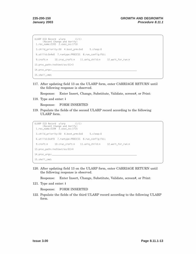
12345678901234567890123456789012123456789012345678901234561234567890123456789012345678901212345678901234567890123456123456789012345678901234567890121234567890123456789012345612345678901234567890123456789012123456789012345678901234561234567890123456789012345678901212345678901234567890123456123456789012345678901234567890121234567890123456789012345612345678901234567890123456789012123456789012345678901234561234567890123456789012345678901212345678901234567890123456123456789012345678901234567890121234567890123456789012345612345678901234567890123456789012123456789012345678901234561234567890123456789012345678901212345678901234567890123456123456789012345678901234567890121234567890123456789012345612345678901234567890123456789012123456789012345678901234561234567890123456789012345678901212345678901234567890123456123456789012345678901234567890121234567890123456789012345612345678901234567890123456789012123456789012345678901234561234567890123456789012345678901212345678901234567890123456123456789012345678901234567890121234567890123456789012345612345678901234567890123456789012123456789012345678901234561234567890123456789012345678901212345678901234567890123456
1234567890123456789012345678901212345678901234567890123456123456789012345678901234567890121234567890123456789012345612345678901234567890123456789012123456789012345678901234561234567890123456789012345678901212345678901234567890123456123456789012345678901234567890121234567890123456789012345612345678901234567890123456789012123456789012345678901234561234567890123456789012345678901212345678901234567890123456123456789012345678901234567890121234567890123456789012345612345678901234567890123456789012123456789012345678901234561234567890123456789012345678901212345678901234567890123456123456789012345678901234567890121234567890123456789012345612345678901234567890123456789012123456789012345678901234561234567890123456789012345678901212345678901234567890123456123456789012345678901234567890121234567890123456789012345612345678901234567890123456789012123456789012345678901234561234567890123456789012345678901212345678901234567890123456123456789012345678901234567890121234567890123456789012345612345678901234567890123456789012123456789012345678901234561234567890123456789012345678901212345678901234567890123456
ULARP ECD Record ularp (1/1)(Recent Change and Verify)
1.rec_name:ECR3 2.exec_no:1710
3.child_priority:50 4.boot_prm:0x0 5.sleep:0
6.utilid:0x4e0 7.runtype:PROCESS 8.run_config:FULL
9.craft:n 10.cruc_craft:n 11.uniq_child:n 12.wait_for_run:n
13.proc_path:/no5text/as/ECr3
14.proc_args:_______________________________________________________________
15.shell_cmd:
117. After updating field 13 on the ULARP form, enter CARRIAGE RETURN untilthe following response is observed.
Response: Enter Insert, Change, Substitute, Validate, screen#, or Print:
118. Type and enter: i
Response: FORM INSERTED
119. Populate the fields of the second ULARP record according to the followingULARP form.
ULARP ECD Record ularp (1/1)(Recent Change and Verify)
1.rec_name:ECR4 2.exec_no:1715
3.child_priority:50 4.boot_prm:0x0 5.sleep:0
6.utilid:0x4f0 7.runtype:PROCESS 8.run_config:FULL
9.craft:n 10.cruc_craft:n 11.uniq_child:n 12.wait_for_run:n
13.proc_path:/no5text/as/ECr4
14.proc_args:_______________________________________________________________
15.shell_cmd:
120. After updating field 13 on the ULARP form, enter CARRIAGE RETURN untilthe following response is observed.
Response: Enter Insert, Change, Substitute, Validate, screen#, or Print:
121. Type and enter: i
Response: FORM INSERTED
122. Populate the fields of the third ULARP record according to the following ULARPform.
235-200-150January 2003
GROWTH AND DEGROWTHProcedure 8.11.1
Issue 3.00 Page 8.11.1-13

12345678901234567890123456789012123456789012345678901234561234567890123456789012345678901212345678901234567890123456123456789012345678901234567890121234567890123456789012345612345678901234567890123456789012123456789012345678901234561234567890123456789012345678901212345678901234567890123456123456789012345678901234567890121234567890123456789012345612345678901234567890123456789012123456789012345678901234561234567890123456789012345678901212345678901234567890123456123456789012345678901234567890121234567890123456789012345612345678901234567890123456789012123456789012345678901234561234567890123456789012345678901212345678901234567890123456123456789012345678901234567890121234567890123456789012345612345678901234567890123456789012123456789012345678901234561234567890123456789012345678901212345678901234567890123456123456789012345678901234567890121234567890123456789012345612345678901234567890123456789012123456789012345678901234561234567890123456789012345678901212345678901234567890123456123456789012345678901234567890121234567890123456789012345612345678901234567890123456789012123456789012345678901234561234567890123456789012345678901212345678901234567890123456
1234567890123456789012345678901212345678901234567890123456123456789012345678901234567890121234567890123456789012345612345678901234567890123456789012123456789012345678901234561234567890123456789012345678901212345678901234567890123456123456789012345678901234567890121234567890123456789012345612345678901234567890123456789012123456789012345678901234561234567890123456789012345678901212345678901234567890123456123456789012345678901234567890121234567890123456789012345612345678901234567890123456789012123456789012345678901234561234567890123456789012345678901212345678901234567890123456123456789012345678901234567890121234567890123456789012345612345678901234567890123456789012123456789012345678901234561234567890123456789012345678901212345678901234567890123456123456789012345678901234567890121234567890123456789012345612345678901234567890123456789012123456789012345678901234561234567890123456789012345678901212345678901234567890123456123456789012345678901234567890121234567890123456789012345612345678901234567890123456789012123456789012345678901234561234567890123456789012345678901212345678901234567890123456
ULARP ECD Record ularp (1/1)(Recent Change and Verify)
1.rec_name:ECR5 2.exec_no:1720
3.child_priority:50 4.boot_prm:0x0 5.sleep:0
6.utilid:0x780 7.runtype:PROCESS 8.run_config:FULL
9.craft:n 10.cruc_craft:n 11.uniq_child:n 12.wait_for_run:n
13.proc_path:/no5text/as/ECr5
14.proc_args:_______________________________________________________________
15.shell_cmd:
123. After updating field 13 on the ULARP form, enter CARRIAGE RETURN untilthe following response is observed.
Response: Enter Insert, Change, Substitute, Validate, screen#, or Print:
124. Type and enter: i
Response: FORM INSERTED
125. Populate the fields of the fourth ULARP record according to the followingULARP form.
ULARP ECD Record ularp (1/1)(Recent Change and Verify)
1.rec_name:ECR6 2.exec_no:1725
3.child_priority:50 4.boot_prm:0x0 5.sleep:0
6.utilid:0x781 7.runtype:PROCESS 8.run_config:FULL
9.craft:n 10.cruc_craft:n 11.uniq_child:n 12.wait_for_run:n
13.proc_path:/no5text/as/ECr6
14.proc_args:_______________________________________________________________
15.shell_cmd:
126. After updating field 13 on the ULARP form, enter CARRIAGE RETURN untilthe following response is observed.
Response: Enter Insert, Change, Substitute, Validate, screen#, or Print:
127. Type and enter: i
Response: FORM INSERTED
128. Populate the fields of the fifth ULARP record according to the following ULARPform.
GROWTH AND DEGROWTHProcedure 8.11.1
235-200-150January 2003
Page 8.11.1-14 Issue 3.00

12345678901234567890123456789012123456789012345678901234561234567890123456789012345678901212345678901234567890123456123456789012345678901234567890121234567890123456789012345612345678901234567890123456789012123456789012345678901234561234567890123456789012345678901212345678901234567890123456123456789012345678901234567890121234567890123456789012345612345678901234567890123456789012123456789012345678901234561234567890123456789012345678901212345678901234567890123456123456789012345678901234567890121234567890123456789012345612345678901234567890123456789012123456789012345678901234561234567890123456789012345678901212345678901234567890123456123456789012345678901234567890121234567890123456789012345612345678901234567890123456789012123456789012345678901234561234567890123456789012345678901212345678901234567890123456123456789012345678901234567890121234567890123456789012345612345678901234567890123456789012123456789012345678901234561234567890123456789012345678901212345678901234567890123456123456789012345678901234567890121234567890123456789012345612345678901234567890123456789012123456789012345678901234561234567890123456789012345678901212345678901234567890123456
1234567890123456789012345678901212345678901234567890123456123456789012345678901234567890121234567890123456789012345612345678901234567890123456789012123456789012345678901234561234567890123456789012345678901212345678901234567890123456123456789012345678901234567890121234567890123456789012345612345678901234567890123456789012123456789012345678901234561234567890123456789012345678901212345678901234567890123456123456789012345678901234567890121234567890123456789012345612345678901234567890123456789012123456789012345678901234561234567890123456789012345678901212345678901234567890123456123456789012345678901234567890121234567890123456789012345612345678901234567890123456789012123456789012345678901234561234567890123456789012345678901212345678901234567890123456123456789012345678901234567890121234567890123456789012345612345678901234567890123456789012123456789012345678901234561234567890123456789012345678901212345678901234567890123456123456789012345678901234567890121234567890123456789012345612345678901234567890123456789012123456789012345678901234561234567890123456789012345678901212345678901234567890123456
ULARP ECD Record ularp (1/1)(Recent Change and Verify)
1.rec_name:ECAP 2.exec_no:1690
3.child_priority:50 4.boot_prm:0x0 5.sleep:0
6.utilid:0x4b0 7.runtype:PROCESS 8.run_config:FULL
9.craft:n 10.cruc_craft:n 11.uniq_child:n 12.wait_for_run:n
13.proc_path:/no5text/as/ECap
14.proc_args:_______________________________________________________________
15.shell_cmd:
129. After updating field 13 on the ULARP form, enter CARRIAGE RETURN untilthe following response is observed.
Response: Enter Insert, Change, Substitute, Validate, screen#, or Print:
130. Type and enter: i
Response: FORM INSERTED
131. Populate the fields of the sixth ULARP record according to the following ULARPform.
ULARP ECD Record ularp (1/1)(Recent Change and Verify)
1.rec_name:ECW3 2.exec_no:1735
3.child_priority:50 4.boot_prm:0x0 5.sleep:0
6.utilid:0x4e0 7.runtype:PROCESS 8.run_config:FULL
9.craft:n 10.cruc_craft:n 11.uniq_child:n 12.wait_for_run:n
13.proc_path:/no5text/as/ECw3
14.proc_args:_______________________________________________________________
15.shell_cmd:
132. After updating field 13 on the ULARP form, enter CARRIAGE RETURN untilthe following response is observed.
Response: Enter Insert, Change, Substitute, Validate, screen#, or Print:
133. Type and enter: i
Response: FORM INSERTED
134. Populate the fields of the seventh ULARP record according to the followingULARP form.
235-200-150January 2003
GROWTH AND DEGROWTHProcedure 8.11.1
Issue 3.00 Page 8.11.1-15

12345678901234567890123456789012123456789012345678901234561234567890123456789012345678901212345678901234567890123456123456789012345678901234567890121234567890123456789012345612345678901234567890123456789012123456789012345678901234561234567890123456789012345678901212345678901234567890123456123456789012345678901234567890121234567890123456789012345612345678901234567890123456789012123456789012345678901234561234567890123456789012345678901212345678901234567890123456123456789012345678901234567890121234567890123456789012345612345678901234567890123456789012123456789012345678901234561234567890123456789012345678901212345678901234567890123456123456789012345678901234567890121234567890123456789012345612345678901234567890123456789012123456789012345678901234561234567890123456789012345678901212345678901234567890123456123456789012345678901234567890121234567890123456789012345612345678901234567890123456789012123456789012345678901234561234567890123456789012345678901212345678901234567890123456123456789012345678901234567890121234567890123456789012345612345678901234567890123456789012123456789012345678901234561234567890123456789012345678901212345678901234567890123456
1234567890123456789012345678901212345678901234567890123456123456789012345678901234567890121234567890123456789012345612345678901234567890123456789012123456789012345678901234561234567890123456789012345678901212345678901234567890123456123456789012345678901234567890121234567890123456789012345612345678901234567890123456789012123456789012345678901234561234567890123456789012345678901212345678901234567890123456123456789012345678901234567890121234567890123456789012345612345678901234567890123456789012123456789012345678901234561234567890123456789012345678901212345678901234567890123456123456789012345678901234567890121234567890123456789012345612345678901234567890123456789012123456789012345678901234561234567890123456789012345678901212345678901234567890123456123456789012345678901234567890121234567890123456789012345612345678901234567890123456789012123456789012345678901234561234567890123456789012345678901212345678901234567890123456123456789012345678901234567890121234567890123456789012345612345678901234567890123456789012123456789012345678901234561234567890123456789012345678901212345678901234567890123456
ULARP ECD Record ularp (1/1)(Recent Change and Verify)
1.rec_name:ECW4 2.exec_no:1740
3.child_priority:50 4.boot_prm:0x0 5.sleep:0
6.utilid:0x4f0 7.runtype:PROCESS 8.run_config:FULL
9.craft:n 10.cruc_craft:n 11.uniq_child:n 12.wait_for_run:n
13.proc_path:/no5text/as/ECw4
14.proc_args:_______________________________________________________________
15.shell_cmd:
135. After updating field 13 on the ULARP form, enter CARRIAGE RETURN untilthe following response is observed.
Response: Enter Insert, Change, Substitute, Validate, screen#, or Print:
136. Type and enter: i
Response: FORM INSERTED
137. Populate the fields of the eighth ULARP record according to the followingULARP form.
ULARP ECD Record ularp (1/1)(Recent Change and Verify)
1.rec_name:ECW5 2.exec_no:1745
3.child_priority:50 4.boot_prm:0x0 5.sleep:0
6.utilid:0x790 7.runtype:PROCESS 8.run_config:FULL
9.craft:n 10.cruc_craft:n 11.uniq_child:n 12.wait_for_run:n
13.proc_path:/no5text/as/ECw5
14.proc_args:_______________________________________________________________
15.shell_cmd:
138. After updating field 13 on the ULARP form, enter CARRIAGE RETURN untilthe following response is observed.
Response: Enter Insert, Change, Substitute, Validate, screen#, or Print:
139. Type and enter: i
Response: FORM INSERTED
140. Populate the fields of the ninth ULARP record according to the following ULARPform.
GROWTH AND DEGROWTHProcedure 8.11.1
235-200-150January 2003
Page 8.11.1-16 Issue 3.00

12345678901234567890123456789012123456789012345678901234561234567890123456789012345678901212345678901234567890123456123456789012345678901234567890121234567890123456789012345612345678901234567890123456789012123456789012345678901234561234567890123456789012345678901212345678901234567890123456123456789012345678901234567890121234567890123456789012345612345678901234567890123456789012123456789012345678901234561234567890123456789012345678901212345678901234567890123456123456789012345678901234567890121234567890123456789012345612345678901234567890123456789012123456789012345678901234561234567890123456789012345678901212345678901234567890123456123456789012345678901234567890121234567890123456789012345612345678901234567890123456789012123456789012345678901234561234567890123456789012345678901212345678901234567890123456123456789012345678901234567890121234567890123456789012345612345678901234567890123456789012123456789012345678901234561234567890123456789012345678901212345678901234567890123456123456789012345678901234567890121234567890123456789012345612345678901234567890123456789012123456789012345678901234561234567890123456789012345678901212345678901234567890123456
ULARP ECD Record ularp (1/1)(Recent Change and Verify)
1.rec_name:ECW6 2.exec_no:1730
3.child_priority:50 4.boot_prm:0x0 5.sleep:0
6.utilid:0x781 7.runtype:PROCESS 8.run_config:FULL
9.craft:n 10.cruc_craft:n 11.uniq_child:n 12.wait_for_run:n
13.proc_path:/no5text/as/ECw6
14.proc_args:_______________________________________________________________
15.shell_cmd:
141. After updating field 13 on the ULARP form, enter CARRIAGE RETURN untilthe following response is observed.
Response: Enter Insert, Change, Substitute, Validate, screen#, or Print:
142. Type and enter: i
Response: FORM INSERTED
143. Type and enter: <
Response: Cursor at Enter Form Name:
144. Type and enter: trend
Response: 1. tr_name: TREND2. dis_cf_checks:n3. apply_tr:y4. o_missing_links:n
145. Enter CARRIAGE RETURN 4 times.
Response: Enter Execute, Change. . .
146. Type and enter: e
Response: ExecutingEnter Form Name:
147. Update UCB for SDL3 to GROW
Type and enter: trbegin
Response: Transaction Begin1.tr_name: TRBEGIN
148. Enter CARRIAGE RETURN
Response: Enter Execute, Change. . .
149. Type and enter: e
150. Type and enter: ucb
Response: Enter Database OperationI=Insert, R=Review, U=Update, D=Delete
151. Type and enter: u and enter CARRIAGE RETURN twice.
Response: Cursor at K_UNIT_NAME
235-200-150January 2003
GROWTH AND DEGROWTHProcedure 8.11.1
Issue 3.00 Page 8.11.1-17

152. Type and enter: SDL
Response: Cursor at K_UNIT_NUMBER
153. Type and enter: 3
Response: Reading...
154. Type and enter: 2 to view screen # 2.
155. Type and enter: c to change a field.
Response: Cursor at Change field:
156. Type and enter: 21 to change the MAJOR_STATUS field.
157. Type and enter: GROW and enter CARRIAGE RETURN
Response: Enter Database OperationI=Insert, R=Review, U=Update, D=Delete
158. Type and enter: u to update the ucb record.
Response: FORM UPDATED
159. Type and enter: <
Response: Cursor at Enter Form Name:
160. Type and enter: trend
Response: 1. tr_name: TREND2. dis_cf_checks:n3. apply_tr:y4. o_missing_links:n
161. Enter CARRIAGE RETURN 4 times.
Response: Enter Execute, Change. . .
162. Type and enter: e
Response: ExecutingEnter Form Name:
163. Update UCB for SDLC3 and SDL3 to OOS State
Type and enter: trbegin
Response: Transaction Begin1.tr_name: TRBEGIN
164. Enter CARRIAGE RETURN
Response: Enter Execute, Change. . .
165. Type and enter: e
166. Type and enter: ucb
Response: Enter Database OperationI=Insert, R=Review, U=Update, D=Delete
167. Type and enter: u and enter CARRIAGE RETURN twice.
Response: Cursor at K_UNIT_NAME
GROWTH AND DEGROWTHProcedure 8.11.1
235-200-150January 2003
Page 8.11.1-18 Issue 3.00

168. Type and enter: SDLC
Response: Cursor at K_UNIT_NUMBER
169. Type and enter: 3
Response: Reading...
170. Type and enter: 2 to view screen # 2.
171. Type and enter: c to change a field.
Response: Cursor at Change field:
172. Type and enter: 21 to change the MAJOR_STATUS field.
173. Type and enter: OOS and enter CARRIAGE RETURN
Response: Enter Database OperationI=Insert, R=Review, U=Update, D=Delete
174. Type and enter: u to update the ucb record.
Response: FORM UPDATED.
175. Type and enter: SDL and enter CARRIAGE RETURN twice.
Response: Cursor at K_UNIT_NUMBER
176. Type and enter: 3
Response: Reading...
177. Type and enter: 2 to view screen # 2.
178. Type and enter: c to change a field.
Response: Cursor at Change field:
179. Type and enter: 21 to change the MAJOR_STATUS field.
180. Type and enter: OOS and enter CARRIAGE RETURN
Response: Enter Database OperationI=Insert, R=Review, U=Update, D=Delete
181. Type and enter: u to update the ucb record.
Response: FORM UPDATED.
182. Type and enter: <
Response: Cursor at Enter Form Name:
183. Type and enter: trend
Response: 1. tr_name: TREND2. dis_cf_checks:n3. apply_tr:y4. o_missing_links:n
184. Enter CARRIAGE RETURN 4 times.
Response: Enter Execute, Change. . .
185. Type and enter: e
Response: ExecutingEnter Form Name:
235-200-150January 2003
GROWTH AND DEGROWTHProcedure 8.11.1
Issue 3.00 Page 8.11.1-19

186. Save ECD Changes to Disk
Type and enter: activate to save the ECD changes to disk.
Response: 1.copy_inc_to_disk:YES
187. Enter CARRIAGE RETURN
Response: Enter Execute, Change. . .
188. Type and enter: e
Response: Executing...
189. Type and enter: < to exit ECD RC/V.
190. THIS IS A SAFE STOPPING POINT, proceed to Procedure 8.11.2
GROWTH AND DEGROWTHProcedure 8.11.1
235-200-150January 2003
Page 8.11.1-20 Issue 3.00

8.11.2 Update RC/V 8.1 for TDMS/EADAS Data Link
PROCEDURE
1. At the MCC or STLWS, type and enter 196 to enter Recent Change and Verify.
Response: PRINT OPTION CR = N ___DETAIL OPTION CR = NVERBOSE OPTION CR = NINPUT Y or N
2. Enter CARRIAGE RETURN 3 times to get to the RECENT CHANGE ANDVERIFY CLASSES page.
3. Type and enter: 8.1u to update recent change view 8.1.
Response: OFFICE PARAMETERS (MISCELLANEOUS) page displayed.Cursor at OFFICE ID attribute.
4. Type and enter the appropriate OFFICE ID for field 1.
Response: System completes remainder of form.Enter Insert, Change, Validate, or Print:
5. Type and enter: c
Response: Change Field:
6. For 5E14, type and enter EADAS
Response: Cursor at EADAS LINK attribute.
For 5E15 and later, type and enter TRFM
Response: Cursor at TRFM LINK attribute.
7. Type and enter: y
Response: Change Field:
8. Enter CARRIAGE RETURN
Response: Enter Update, Change, Validate, or Print:
9. Type and enter: u
Response: updating.....FORM UPDATEDOFFICE PARAMETERS (MISCELLANEOUS) page displayed.Cursor at OFFICE ID attribute.
10. Type and enter: <
Response: 8.0 OFFICE MISCELLANEOUS AND ALARMS VIEWS pagedisplayed.
11. Type and enter: q to quit Recent Change.
Response: RCV-196 COMPLETED
12. THIS IS A SAFE STOPPING POINT.
235-200-150August 2004
GROWTH AND DEGROWTHProcedure 8.11.2
Issue 3.00K Page 8.11.2-1


8.11.3 Connect Hardware for TDMS/EADAS Data Link
PROCEDURE
1. Verify that the internal jumpers of the RS422 to RS232 converter (ED5D764-30G17A, Black Box # IC456A-R4) are set as illustrated in Figure 8.11.3-1
.
2. Connect the RS422 cable (ED5D764-30 G106, Black Box # EDN37J-00XX-MM;where XX is the cable length in feet) between port 3 on the High Speed Interface(HSI) and the RS422 port on the converter.
3. Connect the RS232 male to male cable (Black Box # ECM25C-0010-MM) from theRS232 port on the converter to the Data Communication Equipment (DCE),which may be a modem, DSU2, or router.
4. Plug the converter’s AC power adapter into a UPS 120VAC outlet. Refer toFigures 8.11.3-2 , 8.11.3-3 and 8.11.3-4 for an illustration of the wiringconfiguration for the TDMS/EADAS or RMAS data link.
1. Trademark of Sun Microsystems, Inc.
To 120VACon UPS
RS422port
RS232port
XW1A XW2A XW3A XW4A XW4B XW5A XW5B
XW1BXW2B XW3B
= DIP equipped with shunt
RS422 to RS232 Converter(viewed from top with cover off)
Figure 8.11.3-1 — DIP Shunt Settings for IC456A-R2
235-200-150October 2005
GROWTH AND DEGROWTHProcedure 8.11.3
Issue 3.00B Page 8.11.3-1

High SpeedInterface (HSI)
AdministrativeWorkstation RS422-RS232
Converter (IC456A-R2)
RS422 RS232
120 VAC
DCE(Modem, DSU,or Router)
Facility PSTN/Network
EDN37J-00XX-MMcable
ECM25C-0010-MMcable
PCI
1
PCI
2
PCI
3
PCI
4
Port 0 Port 1 Port 2 Port 3
Figure 8.11.3-2 — Wiring Diagram for TDMS/EADAS or RMAS Data Link ( Netra1 t1120)
High SpeedInterface (HSI)
AdministrativeWorkstation RS422-RS232
Converter (IC456A-R2)
RS422 RS232
120 VAC
DCE(Modem, DSU,or Router)
Facility PSTN/Network
EDN37J-00XX-MMcable
ECM25C-0010-MMcable
PCI
4
PCI
3
PCI
2
PCI
1
Port 0 Port 1 Port 2 Port 3
Figure 8.11.3-3 — Wiring Diagram for TDMS/EADAS or RMAS Data Link ( Netra 20)
GROWTH AND DEGROWTHProcedure 8.11.3
235-200-150October 2005
Page 8.11.3-2 Issue 3.00B

5. THIS IS A SAFE STOPPING POINT.
High SpeedInterface (HSI)
AdministrativeWorkstation RS422-RS232
Converter (IC456A-R2)
RS422 RS232
120 VAC
DCE(Modem, DSU,or Router)
Facility PSTN/Network
EDN37J-00XX-MMcable
ECM25C-0010-MMcable
PCI 2
PCI 1
PCI 0
Port 0 Port 1 Port 2 Port 3
Figure 8.11.3-4 — Wiring Diagram for TDMS/EADAS or RMAS Data Link ( Netra 240)
235-200-150October 2005
GROWTH AND DEGROWTHProcedure 8.11.3
Issue 3.00B Page 8.11.3-3


8.11.4 Define TDMS/EADAS Port on TDMS System
PROCEDURE
1. At this point, the DRM should be defined in the TDMS system. The DRMEADAS/TDMS data link from the DRM must be treated the same as theEADAS/TDMS datalink from a 5ESS® switch.
2. THIS IS A SAFE STOPPING POINT.
235-200-150January 2003
GROWTH AND DEGROWTHProcedure 8.11.4
Issue 3.00 Page 8.11.4-1


8.11.5 Initialize TDMS/EADAS Processes
PROCEDURE
1. At the MCC, type and enter: INIT:ULARP
Response: INIT ULARP COMPLETED
2. At the MCC, type and enter the following commands:
INIT:AM,OKP,SPP,PID=27INIT:AM,OKP,SPP,PID=19INIT:AM,OKP,SPP,PID=80
Note: The following steps are optional but can be used to verify that the correctprocesses are running on the DRM to support the EADAS/TDMS data link. Thesesteps can be used at anytime to verify the processes are active.
3. At the MCC, type and enter poke 194 to go to the SCREEN view. If a STLWSterminal is being used, enter the 120 poke to clear the screen, enter thercv:menu:sh input command, and then skip to step 5.
4. Type and enter: u to request access to the UNIX1 Shell.
5. At the UNIX prompt, type and enter the following command:
ps -axkp | grep "as"
Response: The expected response should be (not necessarily in this order):10 ? 78 /no5text/as/ECap1 ? 98 /no5text/rcv/RCasrsys10 ? 4784235 /no5text/as/ECr310 ? 1638508 /no5text/as/ECr410 ? 110 /no5text/as/AScotsys10 ? 262258 /no5text/as/ECr610 ? 65651 /no5text/as/ECw610 ? 65652 /no5text/as/ECw310 ? 65653 /no5text/as/ECw410 ? 120 grep as
6. In order for the EADAS/TDMS data link to function properly, the ECap, ECr3,ECr4, ECr6, ECw3, ECw4, and ECw6 processes must be listed in the reportindicating that those processes are running.
7. Type and enter: exit at the UNIX prompt.
8. If you are using the MCC, type and enter: q to exit out of the 194 SCREEN view.
9. THIS IS A SAFE STOPPING POINT.
1. Registered trademark in the United States and other countries, licensed exclusively through X/OpenCompany, Limited.
235-200-150January 2003
GROWTH AND DEGROWTHProcedure 8.11.5
Issue 3.00 Page 8.11.5-1


8.11.6 Restore TDMS/EADAS Data Link to Service
PROCEDURE
1. At the MCC, type and enter: RST:SDLC=3 to restore SDLC3 to service.
Response: RST SDLC 3 COMPLETED
THIS IS A SAFE STOPPING POINT, proceed to Procedure 8.11.7
235-200-150January 2003
GROWTH AND DEGROWTHProcedure 8.11.6
Issue 3.00 Page 8.11.6-1


8.11.7 Verify Operation of TDMS/EADAS Data Link
PROCEDURE
1. After SDLC 3 is restored to service, verify that the link goes ACT on MCC page113.
Note: It may take a minute or more for the link to go active.
2. Activate the collection of the TRFC30 data on the DRM by entering the followinginput command on the MCC/STLWS:
ALW:TRFC30,CLCT;
3. At the MCC enter the OP:CLK command to verify that the DRM clock minute isthe same as the TDMS clock +/- 1 minute. If the DRM’s clock is off by more than1 minute, use the SET:CLK command to get it in sync with the TDMS clock.
4. Wait at least 30 minutes for the reports to get generated and then verify thatTDMS received the data.
Note: The next set of steps can be optionally executed to monitor the X.25protocol exchange between the DRM and the EADAS/TDMS OS.
Warning: In order to monitor the X.25 protocol on the EADAS/TDMSdata link, all of the other synchronous data links on the DRM must betemporarily removed from service. The following steps must not beperformed if the DRM is being polled for AMA billing data, if the SCANSlink is active, or if the TNM/SCCS data link is required to be active.
5. Remove all data links from service except the EADAS/TDMS data link by typingand entering the following input command on the MCC/STLWS for each data linkexcept the EADAS/TDMS data link:
RMV:SDL=X; (where X= 0 for SCANS, 13 for AMA, etc)
6. Switch to the Sun1 console by holding down the Control Key and depressing theEnter Key on the MCC’s numeric keypad.
7. Enter CARRIAGE RETURN until the "console login:" prompt appears.
8. Login to the Sun console as root.
9. Type and enter the following command to activate the X.25 protocol analyzerbuilt into the DRM:
/opt/SUNWconn/bin/x25trace -i /dev/lapb x25
Response: Parsed: x25Time Protocol
10. At this point, any X.25 packets sent between the DRM and the EADAS/TDMSOS will be displayed on the Sun console.
11. To exit out of the X.25 protocol analyzer, enter Control c or hit the Delete Key .
12. To go back to the MCC hold down the Control Key and depress the Enter Key onthe MCC’s numeric keypad.
13. THIS IS A SAFE STOPPING POINT, proceed to Procedure 8.11.8
1. Registered trademark of Sun Microsystems, Inc.
235-200-150January 2003
GROWTH AND DEGROWTHProcedure 8.11.7
Issue 3.00 Page 8.11.7-1


8.11.8 Backup Office Dependent Data
PROCEDURE
1. At the MCC, type and enter: BKUP:ODD
Response: BKUP ODD COMPLETED
2. STOP. YOU HAVE COMPLETED THIS PROCEDURE.
235-200-150January 2003
GROWTH AND DEGROWTHProcedure 8.11.8
Issue 3.00 Page 8.11.8-1


8.12 Perform RMAS Data Link Growth
OVERVIEW
This procedure is used to grow the Remote Memory Administration System (RMAS)X.25 data link using ECD low-level forms. This OS uses bx.25 session layer over x.25.This procedure assumes the most common connection, which is using x.25 PVCs overa direct connection between the OS and the datalink (through a Modem, Router,IPDSU, etc).
This procedure assumes the link is to be grown on port 3 of the DRM’s high speedinterface (HSI).
Note: RMAS requires 5e15 and later to work in the DRM.
The following hardware must be on site:
• RS422 to RS232 converter (Black Box part # IC456A)
• RS422 cable (Black Box part # EDN37J-00XX-MM; where XX is the cable lengthin feet)
• RS232 cable (Black Box part # ECM25C-0010-MM)
This procedure takes approximately 2 hours to complete.
PROCEDURE
1. This process is a combination of procedures. Perform these procedures in theorder in which they are presented.
1. “Grow in RMAS Data Link in ECD,” Procedure 8.12.1.
2. “Connect Hardware for RMAS Data Link,” Procedure 8.12.2.
3. “Configure RMAS RC Access,” Procedure 8.12.3.
4. “Verify Operation of RMAS Data Link,” Procedure 8.12.4.
235-200-150January 2006
GROWTH AND DEGROWTHProcedure 8.12
Issue 3.01 Page 8.12-1


12345678901234567890123456789012123456789012345678901234561234567890123456789012345678901212345678901234567890123456123456789012345678901234567890121234567890123456789012345612345678901234567890123456789012123456789012345678901234561234567890123456789012345678901212345678901234567890123456123456789012345678901234567890121234567890123456789012345612345678901234567890123456789012123456789012345678901234561234567890123456789012345678901212345678901234567890123456123456789012345678901234567890121234567890123456789012345612345678901234567890123456789012123456789012345678901234561234567890123456789012345678901212345678901234567890123456123456789012345678901234567890121234567890123456789012345612345678901234567890123456789012123456789012345678901234561234567890123456789012345678901212345678901234567890123456123456789012345678901234567890121234567890123456789012345612345678901234567890123456789012123456789012345678901234561234567890123456789012345678901212345678901234567890123456123456789012345678901234567890121234567890123456789012345612345678901234567890123456789012123456789012345678901234561234567890123456789012345678901212345678901234567890123456
8.12.1 Grow in RMAS Data Link in ECD
OVERVIEW
Warning: ECD forms are case sensitive. Use capital letters where shown.
PROCEDURE
1. Grow in UCB for SDLC3
At MCC, type and enter: 199 to access ECD RC/V.
Response: RCV ECD PARAMETER INFO page displayed with cursor at 1.database_name
2. Type and enter: incore
Response: 2. review only
3. Type and enter: n
Response: 3. journaling
4. Type and enter: *
Response: RCV INITIALIZATION IN PROGRESS message displayed. UNIXRTR RCV (ODIN) - Data Entry page displayed. Cursor at EnterForm Name:
5. Type and enter: trbegin
Response: Transaction Begin1.tr_name: TRBEGIN
6. Enter CARRIAGE RETURN
Response: Enter Execute, Change. . .
7. Type and enter: e
8. Type and enter: ucb
Response: Enter Database OperationI=Insert, R=Review, U=Update, D=Delete
9. Type and enter: i
10. Populate the fields of the UCB record according to the following UCB form:
ucb (1/4)Information About Each Physical Device (Recent Change and Verify)
1.k_complex_name:________ 2.k_complex_number:____
3.k_unit_name:SDLC 4.k_unit_number:3
ucb_type 5.essential:Never 6.top:n 7.unique_unit:y
8.pseudo_node:n 9.restorable:y 10.removable:y
11.device_port:EMUDL 12.device_type:SDLC
13.internal_device:3 14.plant:y
15.critical:y 16.portswitch:n 17.posswitch:
235-200-150January 2003
GROWTH AND DEGROWTHProcedure 8.12.1
Issue 3.00 Page 8.12.1-1

123456789012345678901234567890121234567890123456789012345612345678901234567890123456789012123456789012345678901234561234567890123456789012345678901212345678901234567890123456123456789012345678901234567890121234567890123456789012345612345678901234567890123456789012123456789012345678901234561234567890123456789012345678901212345678901234567890123456123456789012345678901234567890121234567890123456789012345612345678901234567890123456789012123456789012345678901234561234567890123456789012345678901212345678901234567890123456123456789012345678901234567890121234567890123456789012345612345678901234567890123456789012123456789012345678901234561234567890123456789012345678901212345678901234567890123456123456789012345678901234567890121234567890123456789012345612345678901234567890123456789012123456789012345678901234561234567890123456789012345678901212345678901234567890123456123456789012345678901234567890121234567890123456789012345612345678901234567890123456789012123456789012345678901234561234567890123456789012345678901212345678901234567890123456123456789012345678901234567890121234567890123456789012345612345678901234567890123456789012123456789012345678901234561234567890123456789012345678901212345678901234567890123456
12345678901234567890123456789012123456789012345678901234561234567890123456789012345678901212345678901234567890123456123456789012345678901234567890121234567890123456789012345612345678901234567890123456789012123456789012345678901234561234567890123456789012345678901212345678901234567890123456123456789012345678901234567890121234567890123456789012345612345678901234567890123456789012123456789012345678901234561234567890123456789012345678901212345678901234567890123456123456789012345678901234567890121234567890123456789012345612345678901234567890123456789012123456789012345678901234561234567890123456789012345678901212345678901234567890123456123456789012345678901234567890121234567890123456789012345612345678901234567890123456789012123456789012345678901234561234567890123456789012345678901212345678901234567890123456123456789012345678901234567890121234567890123456789012345612345678901234567890123456789012123456789012345678901234561234567890123456789012345678901212345678901234567890123456123456789012345678901234567890121234567890123456789012345612345678901234567890123456789012123456789012345678901234561234567890123456789012345678901212345678901234567890123456
12345678901234567890123456789012123456789012345678901234561234567890123456789012345678901212345678901234567890123456123456789012345678901234567890121234567890123456789012345612345678901234567890123456789012123456789012345678901234561234567890123456789012345678901212345678901234567890123456123456789012345678901234567890121234567890123456789012345612345678901234567890123456789012123456789012345678901234561234567890123456789012345678901212345678901234567890123456
ucb (2/4)
minor_device_status 18.boot:n 19.rexinh:n 20.errlog:n
21.major_status:UNEQIP 22.equipage:
23.device_num:6 24.channel_num:11
25.hv:__________ 26.mt:______ 27.mv:____
28.interrupt_num: 29.service_intrpt:__
30.pathname:pu/sdlc
31.location32.floor:1 33.aisle:a 34.plate:1 35.pack:1
ucb (3/4)
complex_name complex_number unit_name unit_number36.down 37)________ 38)____ 39)________ 40)____
41.side 42)________ 43)____ 44)________ 45)____
46.cntrl_0 47)________ 48)____ 49)__IOP_ 50)__2_
51.cntrl_1 52)________ 53)____ 54)________ 55)____
56.error_table:ioperr 57.option_name:
58.pcid:_3__ 59.pcsdid:0 60.h_type:___
61.handler_id:np
ucb (4/4)
62.packcode:u582 63.issue:2 64.version:
65.cvaddr:0xfff0 66.u_model:
11. After updating field 66 on the UCB form, enter CARRIAGE RETURN.
Response: Enter Insert, Change, Substitute, Validate, screen#, or Print:
12. Type and enter: i
Response: FORM INSERTED
13. Complete steps 14-30 if the SCC data link is not equipped on HSI port 2.Otherwise, if the SCC data link is equipped on HSI port 2, skip to step 31.
14. Warning: Only execute steps 14–30 if no data link is provisioned on HSIport 2.
Type and enter: ^
Response: Enter Database OperationI=Insert, R=Review, U=Update, D=Delete
15. Type and enter: u and enter CARRIAGE RETURN twice.
Response: Cursor at K_UNIT_NAME
GROWTH AND DEGROWTHProcedure 8.12.1
235-200-150January 2003
Page 8.12.1-2 Issue 3.00

16. Type and enter: SDLC
Response: Cursor at K_UNIT_NUMBER
17. Type and enter: 1
Response: Reading...
18. Type and enter: c to change a field.
Response: Cursor at Change field:
19. Type and enter: 44
20. Type and enter: SDLC
Response: Cursor at Change field:
21. Type and enter: 45
22. Type and enter: 3 and then enter a CARRIAGE RETURN
Response: Enter Database OperationI=Insert, R=Review, U=Update, D=Delete
23. Type and enter: u to update the ucb record.
Response: FORM UPDATED
24. Type and enter: <
Response: Cursor at Enter Form Name:
25. Type and enter: trend
Response: 1. tr_name: TREND2. dis_cf_checks:n3. apply_tr:y4. o_missing_links:n
26. Enter CARRIAGE RETURN 4 times.
Response: Enter Execute, Change. . .
27. Type and enter: e
Response: ExecutingEnter Form Name:
28. Go to “Update UCB for SDLC3 to GROW State,” Step 47.
29. Warning: Only execute steps 31–46 if a data link is provisioned on HSIport 2.
Type and enter: ^
Response: Enter Database OperationI=Insert, R=Review, U=Update, D=Delete
30. Type and enter: u and enter CARRIAGE RETURN twice.
Response: Cursor at K_UNIT_NAME
31. Type and enter: SDLC
Response: Cursor at K_UNIT_NUMBER
235-200-150January 2003
GROWTH AND DEGROWTHProcedure 8.12.1
Issue 3.00 Page 8.12.1-3

32. Type and enter: 2
Response: Reading...
33. Type and enter: c to change a field.
Response: Cursor at Change field:
34. Type and enter: 44
35. Type and enter: SDLC
Response: Cursor at Change field:
36. Type and enter: 45
37. Type and enter: 3 and then enter a CARRIAGE RETURN
Response: Enter Database OperationI=Insert, R=Review, U=Update, D=Delete
38. Type and enter: u to update the ucb record.
Response: FORM UPDATED.
39. Type and enter: <
Response: Cursor at Enter Form Name:
40. Type and enter: trend
Response: 1. tr_name: TREND2. dis_cf_checks:n3. apply_tr:y4. o_missing_links:n
41. Enter CARRIAGE RETURN 4 times.
Response: Enter Execute, Change. . .
42. Type and enter: e
Response: ExecutingEnter Form Name:
43. Update UCB for SDLC3 to GROW State
Type and enter: trbegin
Response: Transaction Begin1.tr_name: TRBEGIN
44. Enter CARRIAGE RETURN
Response: Enter Execute, Change. . .
45. Type and enter: e
46. Type and enter: ucb
Response: Enter Database OperationI=Insert, R=Review, U=Update, D=Delete
47. Type and enter: u and enter CARRIAGE RETURN twice.
Response: Cursor at K_UNIT_NAME
GROWTH AND DEGROWTHProcedure 8.12.1
235-200-150January 2003
Page 8.12.1-4 Issue 3.00

48. Type and enter: SDLC
Response: Cursor at K_UNIT_NUMBER
49. Type and enter: 3
Response: Reading...
50. Type and enter: c to change a field.
Response: Cursor at Change field:
51. Type and enter: 21 to change the MAJOR_STATUS field.
52. Type and enter: GROW and then enter CARRIAGE RETURN
Response: Enter Database OperationI=Insert, R=Review, U=Update, D=Delete
53. Type and enter: u to update the ucb record.
Response: FORM UPDATED.
54. Type and enter: <
Response: Cursor at Enter Form Name:
55. Type and enter: trend
Response: 1. tr_name: TREND2. dis_cf_checks:n3. apply_tr:y4. o_missing_links:n
56. Enter CARRIAGE RETURN 4 times.
Response: Enter Execute, Change. . .
57. Type and enter: e
Response: ExecutingEnter Form Name:
58. Insert UCB and NPHOPT for SDL9 and Update SDLC3 to Reference SDL9
Type and enter: trbegin
Response: Transaction Begin1.tr_name: TRBEGIN
59. Enter CARRIAGE RETURN
Response: Enter Execute, Change. . .
60. Type and enter: e
61. Type and enter: ucb
Response: Enter Database OperationI=Insert, R=Review, U=Update, D=Delete
62. Type and enter: i
63. Populate the fields of the UCB record according to the following UCB form:
235-200-150January 2003
GROWTH AND DEGROWTHProcedure 8.12.1
Issue 3.00 Page 8.12.1-5

123456789012345678901234567890121234567890123456789012345612345678901234567890123456789012123456789012345678901234561234567890123456789012345678901212345678901234567890123456123456789012345678901234567890121234567890123456789012345612345678901234567890123456789012123456789012345678901234561234567890123456789012345678901212345678901234567890123456123456789012345678901234567890121234567890123456789012345612345678901234567890123456789012123456789012345678901234561234567890123456789012345678901212345678901234567890123456123456789012345678901234567890121234567890123456789012345612345678901234567890123456789012123456789012345678901234561234567890123456789012345678901212345678901234567890123456123456789012345678901234567890121234567890123456789012345612345678901234567890123456789012123456789012345678901234561234567890123456789012345678901212345678901234567890123456123456789012345678901234567890121234567890123456789012345612345678901234567890123456789012123456789012345678901234561234567890123456789012345678901212345678901234567890123456123456789012345678901234567890121234567890123456789012345612345678901234567890123456789012123456789012345678901234561234567890123456789012345678901212345678901234567890123456
12345678901234567890123456789012123456789012345678901234561234567890123456789012345678901212345678901234567890123456123456789012345678901234567890121234567890123456789012345612345678901234567890123456789012123456789012345678901234561234567890123456789012345678901212345678901234567890123456123456789012345678901234567890121234567890123456789012345612345678901234567890123456789012123456789012345678901234561234567890123456789012345678901212345678901234567890123456123456789012345678901234567890121234567890123456789012345612345678901234567890123456789012123456789012345678901234561234567890123456789012345678901212345678901234567890123456123456789012345678901234567890121234567890123456789012345612345678901234567890123456789012123456789012345678901234561234567890123456789012345678901212345678901234567890123456123456789012345678901234567890121234567890123456789012345612345678901234567890123456789012123456789012345678901234561234567890123456789012345678901212345678901234567890123456123456789012345678901234567890121234567890123456789012345612345678901234567890123456789012123456789012345678901234561234567890123456789012345678901212345678901234567890123456
12345678901234567890123456789012123456789012345678901234561234567890123456789012345678901212345678901234567890123456123456789012345678901234567890121234567890123456789012345612345678901234567890123456789012123456789012345678901234561234567890123456789012345678901212345678901234567890123456123456789012345678901234567890121234567890123456789012345612345678901234567890123456789012123456789012345678901234561234567890123456789012345678901212345678901234567890123456123456789012345678901234567890121234567890123456789012345612345678901234567890123456789012123456789012345678901234561234567890123456789012345678901212345678901234567890123456123456789012345678901234567890121234567890123456789012345612345678901234567890123456789012123456789012345678901234561234567890123456789012345678901212345678901234567890123456123456789012345678901234567890121234567890123456789012345612345678901234567890123456789012123456789012345678901234561234567890123456789012345678901212345678901234567890123456123456789012345678901234567890121234567890123456789012345612345678901234567890123456789012123456789012345678901234561234567890123456789012345678901212345678901234567890123456
12345678901234567890123456789012123456789012345678901234561234567890123456789012345678901212345678901234567890123456123456789012345678901234567890121234567890123456789012345612345678901234567890123456789012123456789012345678901234561234567890123456789012345678901212345678901234567890123456123456789012345678901234567890121234567890123456789012345612345678901234567890123456789012123456789012345678901234561234567890123456789012345678901212345678901234567890123456
ucb (1/4)Information About Each Physical Device (Recent Change and Verify)
1.k_complex_name:________ 2.k_complex_number:____
3.k_unit_name:SDL 4.k_unit_number:9
ucb_type 5.essential:NEVER 6.top:n 7.unique_unit:y
8.pseudo_node:n 9.restorable:y 10.removable:y
11.device_port:EMUDL 12.device_type:SDL
13.internal_device:2 14.plant:y
15.critical:y 16.portswitch:n 17.posswitch:
ucb (2/4)
minor_device_status 18.boot:n 19.rexinh:n 20.errlog:n
21.major_status:UNEQIP 22.equipage:
23.device_num:6 24.channel_num:11
25.hv:__________ 26.mt:______ 27.mv:____
28.interrupt_num: 29.service_intrpt:__
30.pathname:pu/sdl
31.location32.floor:1 33.aisle:a 34.plate:1 35.pack:1
ucb (3/4)
complex_name complex_number unit_name unit_number36.down 37)________ 38)____ 39)________ 40)____
41.side 42)________ 43)____ 44)________ 45)____
46.cntrl_0 47)________ 48)____ 49)_SDLC____ 50)_3__
51.cntrl_1 52)________ 53)____ 54)_________ 55)____
56.error_table:ioperr 57.option_name:rmas
58.pcid:_3__ 59.pcsdid:2 60.h_type:___
61.handler_id:np
ucb (4/4)
62.packcode:____ 63.issue:__ 64.version:__
65.cvaddr:______ 66.u_model:
64. After updating field 59 on the UCB form, enter CARRIAGE RETURN or > untilthe following response is observed.
Response: Enter Insert, Change, Substitute, Validate, screen#, or Print:
GROWTH AND DEGROWTHProcedure 8.12.1
235-200-150January 2003
Page 8.12.1-6 Issue 3.00

12345678901234567890123456789012123456789012345678901234561234567890123456789012345678901212345678901234567890123456123456789012345678901234567890121234567890123456789012345612345678901234567890123456789012123456789012345678901234561234567890123456789012345678901212345678901234567890123456123456789012345678901234567890121234567890123456789012345612345678901234567890123456789012123456789012345678901234561234567890123456789012345678901212345678901234567890123456123456789012345678901234567890121234567890123456789012345612345678901234567890123456789012123456789012345678901234561234567890123456789012345678901212345678901234567890123456123456789012345678901234567890121234567890123456789012345612345678901234567890123456789012123456789012345678901234561234567890123456789012345678901212345678901234567890123456123456789012345678901234567890121234567890123456789012345612345678901234567890123456789012123456789012345678901234561234567890123456789012345678901212345678901234567890123456123456789012345678901234567890121234567890123456789012345612345678901234567890123456789012123456789012345678901234561234567890123456789012345678901212345678901234567890123456
12345678901234567890123456789012123456789012345678901234561234567890123456789012345678901212345678901234567890123456123456789012345678901234567890121234567890123456789012345612345678901234567890123456789012123456789012345678901234561234567890123456789012345678901212345678901234567890123456123456789012345678901234567890121234567890123456789012345612345678901234567890123456789012123456789012345678901234561234567890123456789012345678901212345678901234567890123456123456789012345678901234567890121234567890123456789012345612345678901234567890123456789012123456789012345678901234561234567890123456789012345678901212345678901234567890123456123456789012345678901234567890121234567890123456789012345612345678901234567890123456789012123456789012345678901234561234567890123456789012345678901212345678901234567890123456123456789012345678901234567890121234567890123456789012345612345678901234567890123456789012123456789012345678901234561234567890123456789012345678901212345678901234567890123456
65. Type and enter: i
Response: FORM INSERTED
66. Type and enter: <
Response: Enter Form Name:
67. Type and enter: nphopt
Response: Enter Database OperationI=Insert, R=Review, U=Update, D=Delete
68. Type and enter: i
69. Populate the fields of the NPHOPT record according to the following NPHOPTform.
Note: *There is a version of this form, which does not display the CAUTION atthe top of the screen. As a result, the screen layout will differ slightly from thescreens shown in this step. Make sure that the correct fields are being updatedwith the data shown in this step.
nphopt (1/7)NPH Option Block Record (Recent Change and Verify)
THESE ARE CRITICAL SYSTEM PARAMETERS!! CHANGE WITH EXTREME CAUTION.See Note *
1.option_name:rmas
2.speed: 2400 3.duplex:full 4.ds_type:703CDO
5.carrier:c 6.line_access:private 7.mode_op:b
8.pdtime1:30 9.pdtime2:50 10.window:3
11.rexmit:7 12.dcedte:1
nphopt (2/7)
THESE ARE CRITICAL SYSTEM PARAMETERS!! CHANGE WITH EXTREME CAUTION.See Note *
13.nphldtel sid tlim telno1)______ ____ _____________2)______ ____ ______________3)______ ____ ______________4)______ ____ ______________
17.security:n 18.link_id:0
19.feid_len:0 20.neid_len:0 21.password_len:0
235-200-150January 2003
GROWTH AND DEGROWTHProcedure 8.12.1
Issue 3.00 Page 8.12.1-7

12345678901234567890123456789012123456789012345678901234561234567890123456789012345678901212345678901234567890123456123456789012345678901234567890121234567890123456789012345612345678901234567890123456789012123456789012345678901234561234567890123456789012345678901212345678901234567890123456123456789012345678901234567890121234567890123456789012345612345678901234567890123456789012123456789012345678901234561234567890123456789012345678901212345678901234567890123456123456789012345678901234567890121234567890123456789012345612345678901234567890123456789012123456789012345678901234561234567890123456789012345678901212345678901234567890123456123456789012345678901234567890121234567890123456789012345612345678901234567890123456789012123456789012345678901234561234567890123456789012345678901212345678901234567890123456123456789012345678901234567890121234567890123456789012345612345678901234567890123456789012123456789012345678901234561234567890123456789012345678901212345678901234567890123456
1234567890123456789012345678901212345678901234567890123456123456789012345678901234567890121234567890123456789012345612345678901234567890123456789012123456789012345678901234561234567890123456789012345678901212345678901234567890123456123456789012345678901234567890121234567890123456789012345612345678901234567890123456789012123456789012345678901234561234567890123456789012345678901212345678901234567890123456123456789012345678901234567890121234567890123456789012345612345678901234567890123456789012123456789012345678901234561234567890123456789012345678901212345678901234567890123456123456789012345678901234567890121234567890123456789012345612345678901234567890123456789012123456789012345678901234561234567890123456789012345678901212345678901234567890123456123456789012345678901234567890121234567890123456789012345612345678901234567890123456789012123456789012345678901234561234567890123456789012345678901212345678901234567890123456123456789012345678901234567890121234567890123456789012345612345678901234567890123456789012123456789012345678901234561234567890123456789012345678901212345678901234567890123456
1234567890123456789012345678901212345678901234567890123456123456789012345678901234567890121234567890123456789012345612345678901234567890123456789012123456789012345678901234561234567890123456789012345678901212345678901234567890123456123456789012345678901234567890121234567890123456789012345612345678901234567890123456789012123456789012345678901234561234567890123456789012345678901212345678901234567890123456123456789012345678901234567890121234567890123456789012345612345678901234567890123456789012123456789012345678901234561234567890123456789012345678901212345678901234567890123456123456789012345678901234567890121234567890123456789012345612345678901234567890123456789012123456789012345678901234561234567890123456789012345678901212345678901234567890123456
1234567890123456789012345678901212345678901234567890123456123456789012345678901234567890121234567890123456789012345612345678901234567890123456789012123456789012345678901234561234567890123456789012345678901212345678901234567890123456123456789012345678901234567890121234567890123456789012345612345678901234567890123456789012123456789012345678901234561234567890123456789012345678901212345678901234567890123456123456789012345678901234567890121234567890123456789012345612345678901234567890123456789012123456789012345678901234561234567890123456789012345678901212345678901234567890123456123456789012345678901234567890121234567890123456789012345612345678901234567890123456789012123456789012345678901234561234567890123456789012345678901212345678901234567890123456123456789012345678901234567890121234567890123456789012345612345678901234567890123456789012123456789012345678901234561234567890123456789012345678901212345678901234567890123456123456789012345678901234567890121234567890123456789012345612345678901234567890123456789012123456789012345678901234561234567890123456789012345678901212345678901234567890123456
nphopt (3/7)
THESE ARE CRITICAL SYSTEM PARAMETERS!! CHANGE WITH EXTREME CAUTION.See Note *
22.feid.fend1)____ 4)____ 7)____ 10)____ 13)____2)____ 5)____ 8)____ 11)____ 14)____3)____ 6)____ 9)____ 12)____ 15)____
33.neid.nend1)____ 4)____ 7)____ 10)____ 13)____2)____ 5)____ 8)____ 11)____ 14)____3)____ 6)____ 9)____ 12)____ 15)____
nphopt (4/7)
THESE ARE CRITICAL SYSTEM PARAMETERS!! CHANGE WITH EXTREME CAUTION.See Note *
44.pswrd.pwrd1)____ 4)____ 7)____ 10)____ 13)____2)____ 5)____ 8)____ 11)____ 14)____3)____ 6)____ 9)____ 12)____ 15)____
55.perm_state:allow 56.lana:_______________ 57.estact_chnls:4
58.packetid:X25 59.fast_sel:y 60.fast_accept:y61.connection:DCE 62.num_pvcs:4 63.losvc_1income:____64.hisvc_1income:____ 65.losvc_2way:____ 66.hisvc_2way:____
nphopt (5/7)
THESE ARE CRITICAL SYSTEM PARAMETERS!! CHANGE WITH EXTREME CAUTION.See Note *
67.losvc_1outgo:____ 68.hisvc_1outgo:___ 69.t20_timer:18070.t21_timer:200 71.t22_timer:180 72.t23_timer:18073.t24_timer:60 74.t25_timer:150 75.t26_timer:1876.r20_counter:1 77.r22_counter:1 78.r23_counter:1 79.nstd_ipsize:25680.nstd_opsize:256 81.nstd_iwsize:3 82.nstd_owsize:3
nphopt (6/7)
THESE ARE CRITICAL SYSTEM PARAMETERS!! CHANGE WITH EXTREME CAUTION.See Note *
83.pvcopts
pnstdipsiz pnstdopsiz pnstdiwsiz pnstdowsiz user_name spec_num1)256 256 3 3 sessionlayer 12)256 256 3 3 sessionlayer 23)256 256 3 3 sessionlayer 34)256 256 3 3 sessionlayer 45)___ ___ _ _ _______________ ____________6)___ ___ _ _ _______________ ____________7)___ ___ _ _ _______________ ____________8)___ ___ _ _ _______________ ____________
GROWTH AND DEGROWTHProcedure 8.12.1
235-200-150January 2003
Page 8.12.1-8 Issue 3.00

123456789012345678901234567890121234567890123456789012345612345678901234567890123456789012123456789012345678901234561234567890123456789012345678901212345678901234567890123456123456789012345678901234567890121234567890123456789012345612345678901234567890123456789012123456789012345678901234561234567890123456789012345678901212345678901234567890123456123456789012345678901234567890121234567890123456789012345612345678901234567890123456789012123456789012345678901234561234567890123456789012345678901212345678901234567890123456123456789012345678901234567890121234567890123456789012345612345678901234567890123456789012123456789012345678901234561234567890123456789012345678901212345678901234567890123456123456789012345678901234567890121234567890123456789012345612345678901234567890123456789012123456789012345678901234561234567890123456789012345678901212345678901234567890123456123456789012345678901234567890121234567890123456789012345612345678901234567890123456789012123456789012345678901234561234567890123456789012345678901212345678901234567890123456123456789012345678901234567890121234567890123456789012345612345678901234567890123456789012123456789012345678901234561234567890123456789012345678901212345678901234567890123456
nphopt (7/7)
THESE ARE CRITICAL SYSTEM PARAMETERS!! CHANGE WITH EXTREME CAUTION.See Note *
83.pvcopts(cont)
pnstdipsiz pnstdopsiz pnstdiwsiz pnstdowsiz user_name spec_num9)___ ___ _ _ _______________ ____________10)___ ___ _ _ _______________ ____________11)___ ___ _ _ _______________ ____________
12)___ ___ _ _ ________________ ____________13)___ ___ _ _ ________________ ____________14)___ ___ _ _ ________________ ____________15)___ ___ _ _ ________________ ____________16)___ ___ _ _ ________________ ____________
70. After updating field 83 on the NPHOPT form, enter CARRIAGE RETURN
Response: Enter Insert, Change, Substitute, Validate, screen#, or Print:
71. Type and enter: i
Response: FORM INSERTED
72. Type and enter: <
Response: Enter Form Name:
73. Type and enter: ucb
Response: Enter Database OperationI=Insert, R=Review, U=Update, D=Delete
74. Type and enter: u and enter CARRIAGE RETURN twice.
Response: Cursor at K_UNIT_NAME
75. Type and enter: SDLC
Response: Cursor at K_UNIT_NUMBER
76. Type and enter: 3
Response: Reading...
77. Type and enter: c to change a field.
Response: Cursor at Change field:
78. Type and enter: 39
79. Type and enter: SDL
Response: Cursor at Change field:
80. Type and enter: 40
81. Type and enter: 9 and then enter a CARRIAGE RETURN
Response: Enter Database OperationI=Insert, R=Review, U=Update, D=Delete
82. Type and enter: u to update the ucb record.
Response: FORM UPDATED
235-200-150January 2003
GROWTH AND DEGROWTHProcedure 8.12.1
Issue 3.00 Page 8.12.1-9

12345678901234567890123456789012123456789012345678901234561234567890123456789012345678901212345678901234567890123456123456789012345678901234567890121234567890123456789012345612345678901234567890123456789012123456789012345678901234561234567890123456789012345678901212345678901234567890123456123456789012345678901234567890121234567890123456789012345612345678901234567890123456789012123456789012345678901234561234567890123456789012345678901212345678901234567890123456123456789012345678901234567890121234567890123456789012345612345678901234567890123456789012123456789012345678901234561234567890123456789012345678901212345678901234567890123456123456789012345678901234567890121234567890123456789012345612345678901234567890123456789012123456789012345678901234561234567890123456789012345678901212345678901234567890123456123456789012345678901234567890121234567890123456789012345612345678901234567890123456789012123456789012345678901234561234567890123456789012345678901212345678901234567890123456123456789012345678901234567890121234567890123456789012345612345678901234567890123456789012123456789012345678901234561234567890123456789012345678901212345678901234567890123456
83. Type and enter: <
Response: Cursor at Enter Form Name:
84. Type and enter: trend
Response: 1. tr_name: TREND2. dis_cf_checks:n3. apply_tr:y4. o_missing_links:n
85. Enter CARRIAGE RETURN 4 times.
Response: Enter Execute, Change. . .
86. Type and enter: e
Response: ExecutingEnter Form Name:
87. Insert BXSLLOC and BXSLRMT Forms
Type and enter: trbegin
Response: Transaction Begin1.tr_name: TRBEGIN
88. Enter CARRIAGE RETURN
Response: Enter Execute, Change. . .
89. Type and enter: e
Response: FORM EXECUTED
90. Type and enter: bxslloc
Response: Enter Database OperationI=Insert, R=Review, U=Update, D=Delete
91. Type and enter: u
92. 92. Update the form and verify the fields of the BXSLLOC record are the sameas the following BXSLLOC form:
bxslloc (1/2)Session Layer Local Users List (Recent Change and Verify)
1.loc_name:5ERMAS1
2.loc_addr loc1 loc2 loc3 loc4 loc5 loc6 loc7 loc835 45 52 4d 41 53 31 __
loc9 loc10 loc11 loc12 loc13 loc14 loc15 loc16__ __ __ __ __ __ __ __
19.origin_type:SL 20.sess_dialog:2SIM 21.prs_type:ASCII 22.resync:n
23.recov:n 24.scm_resp_time:260 25.spdu_resp_time:260
26.sresm_resp_time:120 27.srecm_wait_time:300 28.srecm_resp_time:300
GROWTH AND DEGROWTHProcedure 8.12.1
235-200-150January 2003
Page 8.12.1-10 Issue 3.00

12345678901234567890123456789012123456789012345678901234561234567890123456789012345678901212345678901234567890123456123456789012345678901234567890121234567890123456789012345612345678901234567890123456789012123456789012345678901234561234567890123456789012345678901212345678901234567890123456123456789012345678901234567890121234567890123456789012345612345678901234567890123456789012123456789012345678901234561234567890123456789012345678901212345678901234567890123456123456789012345678901234567890121234567890123456789012345612345678901234567890123456789012123456789012345678901234561234567890123456789012345678901212345678901234567890123456
12345678901234567890123456789012123456789012345678901234561234567890123456789012345678901212345678901234567890123456123456789012345678901234567890121234567890123456789012345612345678901234567890123456789012123456789012345678901234561234567890123456789012345678901212345678901234567890123456123456789012345678901234567890121234567890123456789012345612345678901234567890123456789012123456789012345678901234561234567890123456789012345678901212345678901234567890123456123456789012345678901234567890121234567890123456789012345612345678901234567890123456789012123456789012345678901234561234567890123456789012345678901212345678901234567890123456123456789012345678901234567890121234567890123456789012345612345678901234567890123456789012123456789012345678901234561234567890123456789012345678901212345678901234567890123456123456789012345678901234567890121234567890123456789012345612345678901234567890123456789012123456789012345678901234561234567890123456789012345678901212345678901234567890123456123456789012345678901234567890121234567890123456789012345612345678901234567890123456789012123456789012345678901234561234567890123456789012345678901212345678901234567890123456
bxslloc (2/2)
29.spdu_count:2 30.sresm_count:2 31.srecm_count:1 32.scm_count:1
33.procnm:/no5text/rcv/RCmaccntl
34.maxproc:4
93. After updating field 34 on the BXSLLOC form, enter CARRIAGE RETURN
Response: Enter Insert, Change, Substitute, Validate, screen#, or Print:
94. Type and enter: u
Response: FORM UPDATED
95. Type and enter: <
Response: Enter Form Name:
96. Type and enter: bxslrmt
Response: Enter Database OperationI=Insert, R=Review, U=Update, D=Delete
97. Type and enter: i
98. Populate the fields of the BXSLRMT record according to the following BSXLRMTform.
bxslrmt (1/1)Session Layer Remote Users List (Recent Change and Verify)
1.rmt_name:RMAS
2.rmt_addr rmt1 rmt2 rmt3 rmt4 rmt5 rmt6 rmt7 rmt852 4d 41 53 __ __ __ __rmt9 rmt10 rmt11 rmt12 rmt13 rmt14 rmt15 rmt16__ __ __ __ __ __ __ __
19.remote_dte addr_type address1) PVC 12) PVC 23) PVC 34) PVC 4
99. After updating field 19 on the BXSLRMT form, enter CARRIAGE RETURN untilthe following response is observed.
Response: Enter Insert, Change, Substitute, Validate, screen#, or Print:
100. Type and enter: i
Response: FORM INSERTED
101. Type and enter: <
Response: Enter Form Name:
235-200-150January 2003
GROWTH AND DEGROWTHProcedure 8.12.1
Issue 3.00 Page 8.12.1-11

123456789012345678901234567890121234567890123456789012345612345678901234567890123456789012123456789012345678901234561234567890123456789012345678901212345678901234567890123456123456789012345678901234567890121234567890123456789012345612345678901234567890123456789012123456789012345678901234561234567890123456789012345678901212345678901234567890123456123456789012345678901234567890121234567890123456789012345612345678901234567890123456789012123456789012345678901234561234567890123456789012345678901212345678901234567890123456123456789012345678901234567890121234567890123456789012345612345678901234567890123456789012123456789012345678901234561234567890123456789012345678901212345678901234567890123456123456789012345678901234567890121234567890123456789012345612345678901234567890123456789012123456789012345678901234561234567890123456789012345678901212345678901234567890123456
102. Type and enter: trend
Response: 1. tr_name: TREND2. dis_cf_checks:n3. apply_tr:y4. o_missing_links:n
103. Enter CARRIAGE RETURN 4 times.
Response: Enter Execute, Change. . .
104. Type and enter: e
Response: ExecutingEnter Form Name:
105. Insert MDCT and LOGDEV Forms
Type and enter: trbegin
Response: Transaction Begin1.tr_name: TRBEGIN
106. Enter CARRIAGE RETURN
Response: Enter Execute, Change. . .
107. Type and enter: e
108. Type and enter: mdct
Response: Enter Database OperationI=Insert, R=Review, U=Update, D=Delete
109. Type and enter: i
110. Populate the fields of the first MDCT record according to the following MDCTform.
Note: In the following form, Field 3 (mdct_type) is set to the lower case letter“l”.
mdct (1/3)Logical To Physical Device Transaction (Recent Change and Verify)
1.mdct_name:RMAS 2.logical_device:io
3.mdct_type:l 4.mdct_id_char:0
5.active_devices6.complex_name 7.complex_number 8.unit_name 9.unit_number1)________ ____ SDL 92)________ ____ ________ ____3)________ ____ ________ ____4)________ ____ ________ ____
GROWTH AND DEGROWTHProcedure 8.12.1
235-200-150January 2003
Page 8.12.1-12 Issue 3.00

12345678901234567890123456789012123456789012345678901234561234567890123456789012345678901212345678901234567890123456123456789012345678901234567890121234567890123456789012345612345678901234567890123456789012123456789012345678901234561234567890123456789012345678901212345678901234567890123456123456789012345678901234567890121234567890123456789012345612345678901234567890123456789012123456789012345678901234561234567890123456789012345678901212345678901234567890123456123456789012345678901234567890121234567890123456789012345612345678901234567890123456789012123456789012345678901234561234567890123456789012345678901212345678901234567890123456123456789012345678901234567890121234567890123456789012345612345678901234567890123456789012123456789012345678901234561234567890123456789012345678901212345678901234567890123456123456789012345678901234567890121234567890123456789012345612345678901234567890123456789012123456789012345678901234561234567890123456789012345678901212345678901234567890123456123456789012345678901234567890121234567890123456789012345612345678901234567890123456789012123456789012345678901234561234567890123456789012345678901212345678901234567890123456
1234567890123456789012345678901212345678901234567890123456123456789012345678901234567890121234567890123456789012345612345678901234567890123456789012123456789012345678901234561234567890123456789012345678901212345678901234567890123456123456789012345678901234567890121234567890123456789012345612345678901234567890123456789012123456789012345678901234561234567890123456789012345678901212345678901234567890123456123456789012345678901234567890121234567890123456789012345612345678901234567890123456789012123456789012345678901234561234567890123456789012345678901212345678901234567890123456123456789012345678901234567890121234567890123456789012345612345678901234567890123456789012123456789012345678901234561234567890123456789012345678901212345678901234567890123456
1234567890123456789012345678901212345678901234567890123456123456789012345678901234567890121234567890123456789012345612345678901234567890123456789012123456789012345678901234561234567890123456789012345678901212345678901234567890123456123456789012345678901234567890121234567890123456789012345612345678901234567890123456789012123456789012345678901234561234567890123456789012345678901212345678901234567890123456123456789012345678901234567890121234567890123456789012345612345678901234567890123456789012123456789012345678901234561234567890123456789012345678901212345678901234567890123456123456789012345678901234567890121234567890123456789012345612345678901234567890123456789012123456789012345678901234561234567890123456789012345678901212345678901234567890123456123456789012345678901234567890121234567890123456789012345612345678901234567890123456789012123456789012345678901234561234567890123456789012345678901212345678901234567890123456
mdct (2/3)
10.backup_devices11.complex_name 12.complex_number 13.unit_name 14.unit_number1)________ ____ ________ ____2)________ ____ ________ ____3)________ ____ ________ ____4)________ ____ ________ ____
15.spare_devices16.complex_name 17.complex_number 18.unit_name 19.unit_number
1)________ ____ ________ ____2)________ ____ ________ ____3)________ ____ ________ ____4)________ ____ ________ ____
mdct (3/3)
20.oos_devices21.complex_name 22.complex_number 23.unit_name 24.unit_number
1)________ ____ ________ ____2)________ ____ ________ ____3)________ ____ ________ ____4)________ ____ ________ ____
25.gettyid:________
111. After updating field 25 on the MDCT form, enter CARRIAGE RETURN until thefollowing response is observed.
Response: Enter Insert, Change, Substitute, Validate, screen#, or Print:
112. Type and enter: i
Response: FORM INSERTED
113. Type and enter: <
Response: Enter Form Name:
114. Type and enter: logdev
Response: Enter Database OperationI=Insert, R=Review, U=Update, D=Delete
115. Type and enter: i
116. Populate the fields of the LOGDEV record according to the following LOGDEVform.
logdev (1/1)Logical Device Information (Recent Change and Verify)
1.logical_name:/dev/rmas1 2.partition:0x1
3.mdct_name:RMAS 4.channel_id:___
5.dcn:23 6.driver_type:c
7.gettyid:________ 8.usr:rw-
9.grp:rw- 10.other:---
235-200-150January 2003
GROWTH AND DEGROWTHProcedure 8.12.1
Issue 3.00 Page 8.12.1-13

1234567890123456789012345678901212345678901234567890123456123456789012345678901234567890121234567890123456789012345612345678901234567890123456789012123456789012345678901234561234567890123456789012345678901212345678901234567890123456123456789012345678901234567890121234567890123456789012345612345678901234567890123456789012123456789012345678901234561234567890123456789012345678901212345678901234567890123456123456789012345678901234567890121234567890123456789012345612345678901234567890123456789012123456789012345678901234561234567890123456789012345678901212345678901234567890123456123456789012345678901234567890121234567890123456789012345612345678901234567890123456789012123456789012345678901234561234567890123456789012345678901212345678901234567890123456123456789012345678901234567890121234567890123456789012345612345678901234567890123456789012123456789012345678901234561234567890123456789012345678901212345678901234567890123456
123456789012345678901234567890121234567890123456789012345612345678901234567890123456789012123456789012345678901234561234567890123456789012345678901212345678901234567890123456123456789012345678901234567890121234567890123456789012345612345678901234567890123456789012123456789012345678901234561234567890123456789012345678901212345678901234567890123456123456789012345678901234567890121234567890123456789012345612345678901234567890123456789012123456789012345678901234561234567890123456789012345678901212345678901234567890123456123456789012345678901234567890121234567890123456789012345612345678901234567890123456789012123456789012345678901234561234567890123456789012345678901212345678901234567890123456123456789012345678901234567890121234567890123456789012345612345678901234567890123456789012123456789012345678901234561234567890123456789012345678901212345678901234567890123456
117. After updating field 10 on the LOGDEV form, enter CARRIAGE RETURN untilthe following response is observed.
Response: Enter Insert, Change, Substitute, Validate, screen#, or Print:
118. Type and enter: i
Response: FORM INSERTED
119. Populate the fields of the second LOGDEV record according to the followingLOGDEV form.
logdev (1/1)Logical Device Information (Recent Change and Verify)
1.logical_name:/dev/rmas2 2.partition:0x2
3.mdct_name:RMAS 4.channel_id:___
5.dcn:23 6.driver_type:c
7.gettyid:_________ 8.usr:rw-
9.grp:rw- 10.other:---
120. After updating field 19 on the LOGDEV form, enter CARRIAGE RETURN untilthe following response is observed.
Response: Enter Insert, Change, Substitute, Validate, screen#, or Print:
121. Type and enter: i
Response: FORM INSERTED
122. Populate the fields of the third LOGDEV record according to the followingLOGDEV form.
logdev (1/1)Logical Device Information (Recent Change and Verify)
1.logical_name:/dev/rmas3 2.partition:0x3
3.mdct_name:RMAS 4.channel_id:___
5.dcn:23 6.driver_type:c
7.gettyid:________ 8.usr:rw-
9.grp:rw- 10.other:---
123. After updating field 10 on the LOGDEV form, enter CARRIAGE RETURN untilthe following response is observed.
Response: Enter Insert, Change, Substitute, Validate, screen#, or Print:
124. Type and enter: i
Response: FORM INSERTED
125. Populate the fields of the fourth LOGDEV record according to the followingLOGDEV form.
GROWTH AND DEGROWTHProcedure 8.12.1
235-200-150January 2003
Page 8.12.1-14 Issue 3.00

12345678901234567890123456789012123456789012345678901234561234567890123456789012345678901212345678901234567890123456123456789012345678901234567890121234567890123456789012345612345678901234567890123456789012123456789012345678901234561234567890123456789012345678901212345678901234567890123456123456789012345678901234567890121234567890123456789012345612345678901234567890123456789012123456789012345678901234561234567890123456789012345678901212345678901234567890123456123456789012345678901234567890121234567890123456789012345612345678901234567890123456789012123456789012345678901234561234567890123456789012345678901212345678901234567890123456123456789012345678901234567890121234567890123456789012345612345678901234567890123456789012123456789012345678901234561234567890123456789012345678901212345678901234567890123456123456789012345678901234567890121234567890123456789012345612345678901234567890123456789012123456789012345678901234561234567890123456789012345678901212345678901234567890123456
1234567890123456789012345678901212345678901234567890123456123456789012345678901234567890121234567890123456789012345612345678901234567890123456789012123456789012345678901234561234567890123456789012345678901212345678901234567890123456123456789012345678901234567890121234567890123456789012345612345678901234567890123456789012123456789012345678901234561234567890123456789012345678901212345678901234567890123456123456789012345678901234567890121234567890123456789012345612345678901234567890123456789012123456789012345678901234561234567890123456789012345678901212345678901234567890123456123456789012345678901234567890121234567890123456789012345612345678901234567890123456789012123456789012345678901234561234567890123456789012345678901212345678901234567890123456123456789012345678901234567890121234567890123456789012345612345678901234567890123456789012123456789012345678901234561234567890123456789012345678901212345678901234567890123456
logdev (1/1)Logical Device Information (Recent Change and Verify)
1.logical_name:/dev/rmas4 2.partition:0x4
3.mdct_name:RMAS 4.channel_id:___
5.dcn:23 6.driver_type:c
7.gettyid:________ 8.usr:rw-
9.grp:rw- 10.other:---
126. After updating field 130 on the LOGDEV form, enter CARRIAGE RETURN untilthe following response is observed.
Response: Enter Insert, Change, Substitute, Validate, screen#, or Print:
127. Type and enter: i
Response: FORM INSERTED
128. Type and enter: ^
Response: Enter Database OperationI=Insert, R=Review, U=Update, D=Delete
129. Type and enter: u:
130. Change any of the fields in this LOGDEV record to match the following LOGDEVform.
logdev (1/1)Logical Device Information (Recent Change and Verify)
1.logical_name:/dev/bx25session 2.partition:0x5
3.mdct_name:bx25sess 4.channel_id:___
5.dcn:23 6.driver_type:c
7.gettyid:________ 8.usr:rwx
9.grp:r-x 10.other:---
131. Type and enter: u
Response: FORM UPDATED
132. Type and enter: <
Response: Cursor at Enter Form Name:
133. Type and enter: trend
Response: 1. tr_name: TREND2. dis_cf_checks:n3. apply_tr:y4. o_missing_links:n
134. Enter CARRIAGE RETURN 4 times.
Response: Enter Execute, Change. . .
235-200-150January 2003
GROWTH AND DEGROWTHProcedure 8.12.1
Issue 3.00 Page 8.12.1-15

135. Type and enter: e
Response: ExecutingEnter Form Name:
136. Update UCB for SDL9 to GROW
Type and enter: trbegin
Response: Transaction Begin1.tr_name: TRBEGIN
137. Enter CARRIAGE RETURN
Response: Enter Execute, Change. . .
138. Type and enter: e
139. Type and enter: ucb
Response: Enter Database OperationI=Insert, R=Review, U=Update, D=Delete
140. Type and enter: u and enter CARRIAGE RETURN twice.
Response: Cursor at K_UNIT_NAME
141. Type and enter: SDL
Response: Cursor at K_UNIT_NUMBER
142. Type and enter: 9
Response: Reading...
143. Type and enter: c to change a field.
Response: Cursor at Change field:
144. Type and enter: 21 to change the MAJOR_STATUS field.
145. Type and enter: GROW and enter CARRIAGE RETURN
Response: Enter Database OperationI=Insert, R=Review, U=Update, D=Delete
146. Type and enter: u to update the ucb record.
Response: FORM UPDATED
147. Type and enter: <
Response: Cursor at Enter Form Name:
148. Type and enter: trend
Response: 1. tr_name: TREND2. dis_cf_checks:n3. apply_tr:y4. o_missing_links:n
149. Enter CARRIAGE RETURN 4 times.
Response: Enter Execute, Change. . .
GROWTH AND DEGROWTHProcedure 8.12.1
235-200-150January 2003
Page 8.12.1-16 Issue 3.00

150. Type and enter: e
Response: ExecutingEnter Form Name:
151. Update UCB for SDLC3 and SDL9 to OOS State
Type and enter: trbegin
Response: Transaction Begin1.tr_name: TRBEGIN
152. Enter CARRIAGE RETURN
Response: Enter Execute, Change. . .
153. Type and enter: e
154. Type and enter: ucb
Response: Enter Database OperationI=Insert, R=Review, U=Update, D=Delete
155. Type and enter: u and enter CARRIAGE RETURN twice.
Response: Cursor at K_UNIT_NAME
156. Type and enter: SDLC
Response: Cursor at K_UNIT_NUMBER
157. Type and enter: 3
Response: Reading...
158. Type and enter: c to change a field.
Response: Cursor at Change field:
159. Type and enter: 21 to change the MAJOR_STATUS field.
160. Type and enter: OOS and enter CARRIAGE RETURN
Response: Enter Database OperationI=Insert, R=Review, U=Update, D=Delete
161. Type and enter: u to update the ucb record.
Response: FORM UPDATED.
162. Type and enter: SDL and enter CARRIAGE RETURN twice.
Response: Cursor at K_UNIT_NUMBER
163. Type and enter: 9
Response: Reading...
164. Type and enter: 2 to view screen # 2.
165. Type and enter: c to change a field.
Response: Cursor at Change field:
166. Type and enter: 21 to change the MAJOR_STATUS field.
235-200-150January 2003
GROWTH AND DEGROWTHProcedure 8.12.1
Issue 3.00 Page 8.12.1-17

167. Type and enter: OOS and enter CARRIAGE RETURN
Response: Enter Database OperationI=Insert, R=Review, U=Update, D=Delete
168. Type and enter: u to update the ucb record.
Response: FORM UPDATED.
169. Type and enter: <
Response: Cursor at Enter Form Name:
170. Type and enter: trend
Response: 1. tr_name: TREND2. dis_cf_checks:n3. apply_tr:y4. o_missing_links:n
171. Enter CARRIAGE RETURN 4 times.
Response: Enter Execute, Change. . .
172. Type and enter: e
Response: ExecutingEnter Form Name:
173. Save ECD Changes to Disk
Type and enter: activate to save the ECD changes to disk.
Response: 1.copy_inc_to_disk:YES
174. Enter CARRIAGE RETURN
Response: Enter Execute, Change. . .
175. Type and enter: e
Response: Executing...
176. Type and enter: < to exit ECD RC/V.
177. Go to the EAI page on the MCC terminal and execute the 58 Boot+UX (UNIX)command.
178. Go to page 113 and verify RMAS link shows up.
GROWTH AND DEGROWTHProcedure 8.12.1
235-200-150January 2003
Page 8.12.1-18 Issue 3.00

8.12.2 Connect Hardware for RMAS Data Link
PROCEDURE
1. Verify that the internal jumpers of the RS422 to RS232 converter (ED5D764-30G17A, Black Box # IC456A-R4) are set as illustrated in Figure 8.11.3-1.
2. Connect the RS422 cable (ED5D764-30 G106, Black Box # EDN37J-00XX-MM;where XX is the cable length in feet) between port 3 on the High Speed Interface(HSI) and the RS422 port on the converter.
3. Connect the RS232 male to male cable (Black Box # ECM25C-0010-MM) from theRS232 port on the converter to the Data Communication Equipment (DCE),which may be a modem, DSU2, or router.
4. Plug the converter’s AC power adapter into a UPS 120VAC outlet. Refer toFigures 8.11.3-2 , 8.11.3-3 and 8.11.3-4 for an illustration of the wiringconfiguration for the TDMS/EADAS or RMAS data link.
5. THIS IS A SAFE STOPPING POINT.
235-200-150January 2006
GROWTH AND DEGROWTHProcedure 8.12.2
Issue 3.02 Page 8.12.2-1


8.12.3 Configure RMAS RC Access
PROCEDURE
1. At the MCC, type and enter: RST:SDLC=3 to restore SDLC3 to service
Response: RST SDLC 3 COMPLETED
2. At the MCC, type and enter SET:RCACCESS,TTY=”RCOS4”,ACCESS=a;
Where: a = Obtained from the 235–600–700Input Messages Manual(iea=1–29,33”)
3. Type and enter: OP:RCACCESS,TTYP=”RCOS4”;
Response: Access code will be returned in hexadecimal.
4. Repeat Steps 2 and 3 for TTYp changles “RCOS5”, “RCOS6”, and “RCOS7”.
5. Type and enter: BKUP:ODD;
6. THIS IS A SAFE STOPPING POINT.
235-200-150January 2003
GROWTH AND DEGROWTHProcedure 8.12.3
Issue 3.00 Page 8.12.3-1


8.12.4 Verify Operation of RMAS Data Link
PROCEDURE
1. After SDLC 3 is restored to service, verify that the link goes ACT on MCC page113.
Note: This section is OPTIONAL: The next set of steps can be optionallyexecuted to monitor the X.25 protocol exchange between the DRM and the RMASOS.
2. Switch to the Sun1 console by holding down the Control Key and depressing theEnter Key on the MCC’s numeric keypad.
3. Enter CARRIAGE RETURN until the "console login:" prompt appears.
4. Type and enter the following command to activate the X.25 protocol analyzerbuilt into the DRM:
/opt/SUNWconn/bin/x25trace -i /dev/lapb -l 3 x25
Response: Parsed: x25Time Protocol
5. At this point, any X.25 packets sent between the DRM and the RMAS OS will bedisplayed on the Sun console.
6. To exit out of the X.25 protocol analyzer, enter Control c or hit the Delete Key .
7. Type exit to exit from root login in the Sun console.
8. To go back to the MCC hold down the Control Key and depress the Enter Key onthe MCC’s numeric keypad.
9. STOP. YOU HAVE COMPLETED THIS PROCEDURE
1. Registered trademark of Sun Microsystems, Inc.
235-200-150January 2003
GROWTH AND DEGROWTHProcedure 8.12.4
Issue 3.00 Page 8.12.4-1


8.13 Perform Traffic Printer Growth
PROCEDURE
1. Enter UNIX1 RTR Recent Change and Verify.
(a) Is MCC or STLWS terminal to be used?
For MCC, proceed to Step b.For STLWS proceed to Step i.
(b) At MCC, ensure terminal is in command mode.
(c) At MCC, do Steps d through h.
(d) Type and enter: 199
Response: RCV PARAMETER INFO page displayed with cursor at 1.database_name
(e) Type and enter: incore
Response: 2. review only
(f) Type and enter: n
Response: 3. journaling
(g) Type and enter: *
Response: RCV INITIALIZATION IN PROGRESS message displayed.UNIX RTR RCV (ODIN) - Data Entry page displayed.
(h) You have completed Enter UNIX RTR Recent Change and Verify, proceed toStep 2.
(i) At STLWS terminal, type and enter: RCV:MENU:DATA,RCVECD
Response: RCV ECD PARAMETER INFO page displayed with cursor at 1.database_name
(j) Type and enter: incore
Response: 2. review only
(k) Type and enter: n
Response: 3. journaling
(l) Type and enter: *
Response: RCV INITIALIZATION IN PROGRESS message displayed.UNIX RTR RCV (ODIN) - Data Entry page displayed. Cursorat Enter Form Name:
2. Enter high-level forms.
(a) Type and enter: toggle
Response: Will take you to the high-level forms.
3. Insert TTY data.
1. Registered trademark in the United States and other countries, licensed exclusively through X/OpenCompany, Limited.
235-200-150October 2005
GROWTH AND DEGROWTHProcedure 8.13
Issue 3.01 Page 8.13-1

(a) Type and enter: ttyadd
Response: ttyadd form displayed. Cursor at 1.tty_name:
Note: An ! may be entered any time prompted to abort the form andreturn to the state when the form was started.
(b) Type and enter the following data:
1. tty_namea: enter TTY72. baud_rate: enter (as specified or CARRIAGE RETURN)3. login_term: enter (as specified or CARRIAGE RETURN)4. auth_chk: enter (as specified or CARRIAGE RETURN)5. term_type: enter (as specified or CARRIAGE RETURN)6. line_mode: enter (as specified or CARRIAGE RETURN)7. port: enter 2 or 3 for TTYC port (see Table 8.3-1 and
8.3-2)8. ttyc_number: enter TTYC number base on SAI port (see Table
8.3-1 and 8.3-2)9. plu_unit_name: enter CARRIAGE RETURN10. plu_unit_number: enter CARRIAGE RETURNNote(s):a. tty_name must be entered in all capital letters.
Note: Fields not specified receive the default value by enteringCARRIAGE RETURN.
Note: When growing a TTY terminal a defensive check failure messageREPT CONFIG FAULT Assert = 412 may be received. This failure messagemay be ignored.
4. Install the traffic printer to the SAI port corresponding to the TTYC port andTTYC number chosen in Tables 8.3-1 and 8.3-2 (see Figures 8.13-1 , 8.13-2 and8.13-3).
(a) Enter CARRIAGE RETURN
2. Trademark of Sun Microsystems, Inc.
GROWTH AND DEGROWTHProcedure 8.13
235-200-150October 2005
Page 8.13-2 Issue 3.01

PO RT 7
PO RT 0
PO RT 1
PO RT 2
PO RT 3
PO RT 4
PO RT 5
PO RT 6
Asynchr onousPatch Panel
SAI-1(O ptional )PO RT 7
PO RT 0
PO RT 1
PO RT 2
PO RT 3
PO RT 4
PO RT 5
PO RT 6
Asynchr onousPatch Panel
SAI-0
PCI1
PCI2
PCI3
PCI4
To Traffic Printer
Figure 8.13-1 — Traffic Printer Installation ( Netra2 t 1120)
PO RT 7
PO RT 0
PO RT 1
PO RT 2
PO RT 3
PO RT 4
PO RT 5
PO RT 6
AsynchronousPatch Panel
SAI-1(Optional)
PO RT 7
PO RT 0
PO RT 1
PO RT 2
PO RT 3
PO RT 4
PO RT 5
PO RT 6
AsynchronousPatch Panel
SAI-0
To Traffic Printer
Figure 8.13-2 — Traffic Printer Installation ( Netra 20)
235-200-150October 2005
GROWTH AND DEGROWTHProcedure 8.13
Issue 3.01 Page 8.13-3

5. Restore TTY x to service.
(a) At MCC, type and enter the appropriate message:
RST:TTY=x
Where: x = appropriate TTY number.
Response: RST TTY x COMPLETED
(b) Enter CARRIAGE RETURN
Response: FORM INSERTED
(c) Type and enter: <
Response: Exit the ttyadd form.
(d) Type and enter: <
Response: Exit this recent change session.
6. Backup Incore ECD to disk.
(a) At MCC, do Steps b through i.
Figure 8.13-3 — Traffic Printer Installation ( Netra 240)
GROWTH AND DEGROWTHProcedure 8.13
235-200-150October 2005
Page 8.13-4 Issue 3.01

(b) Type and enter: 199
Response: RCV PARAMETER INFO page displayed with cursor at 1.database_name
(c) Type and enter: incore
Response: 2. review only
(d) Type and enter: n
Response: 3. journaling
(e) Type and enter: *
Response: UNIX RTR (ODIN) - Data Entry page displayed.
(f) Type and enter: activate
Response: activate form displayed with cursor at 1. copy_inc_to_disk:
(g) Type and enter: yes
Response: ODIN will request the action desired.
(h) Type and enter: e
Response: ODIN returns to the UNIX RTR (ODIN) - Data Entry page.
(i) Type and enter: <
Response: RCV MENU RCV ECD COMPLETED
7. Backup Office Dependent Data.
Note: Prior to the response there will be completed responses for the switchingmodule and the AM.
a. At MCC, type and enter: BKUP:ODD
Response: BKUP ODD COMPLETED
It is recommended that primary disk be backed up and that a shelf copy ofthe disks be made.
8. STOP. YOU HAVE COMPLETED THIS PROCEDURE.
235-200-150October 2005
GROWTH AND DEGROWTHProcedure 8.13
Issue 3.01 Page 8.13-5


8.14 Perform Office Record Printer Growth
PROCEDURE
1. Enter UNIX1 RTR Recent Change and Verify.
(a) Is MCC or STLWS terminal to be used?
For MCC, proceed to Step b.For STLWS proceed to Step i.
(b) At MCC, ensure terminal is in command mode.
(c) At MCC, do Steps d through h.
(d) Type and enter: 199
Response: RCV PARAMETER INFO page displayed with cursor at 1.database_name
(e) Type and enter: incore
Response: 2. review only
(f) Type and enter: n
Response: 3. journaling
(g) Type and enter: *
Response: RCV INITIALIZATION IN PROGRESS message displayed.UNIX RTR RCV (ODIN) - Data Entry page displayed.
(h) You have completed Enter UNIX RTR Recent Change and Verify, proceed toStep 2.
(i) At STLWS terminal, type and enter: RCV:MENU:DATA,RCVECD
Response: RCV ECD PARAMETER INFO page displayed with cursor at 1.database_name
(j) Type and enter: incore
Response: 2. review only
(k) Type and enter: n
Response: 3. journaling
(l) Type and enter: *
Response: RCV INITIALIZATION IN PROGRESS message displayed.UNIX RTR RCV (ODIN) - Data Entry page displayed. Cursorat Enter Form Name:
2. Enter high-level forms.
(a) Type and enter: toggle
Response: Will take you to the high-level forms.
3. Insert TTY data.
1. Registered trademark in the United States and other countries, licensed exclusively through X/OpenCompany, Limited.
235-200-150October 2005
GROWTH AND DEGROWTHProcedure 8.14
Issue 3.00B Page 8.14-1

(a) Type and enter: ttyadd
Response: ttyadd form displayed. Cursor at 1.tty_name:
Note: An ! may be entered any time prompted to abort the form andreturn to the state when the form was started.
Note: Fields not specified receive the default value by enteringCARRIAGE RETURN.
(b) Type and enter the following data:
1. tty_namea: enter TTY432. baud_rate: enter CARRIAGE RETURNb
3. login_term: enter CARRIAGE RETURN4. auth_chk: enter CARRIAGE RETURN5. term_type: enter CARRIAGE RETURN6. line_mode: enter CARRIAGE RETURN7. port: enter 2 or 3 for TTYC port (see Tables 8.3-1 and
8.3-2)8. ttyc_number: enter TTYC number base on SAI port (see Tables
8.3-1 and 8.3-2)9. plu_unit_name: enter CARRIAGE RETURN
10. plu_unit_number enter CARRIAGE RETURNNote(s):a. tty_name must be entered in all capital letters.b. The default baud rate is 1200. If a different baud rate is desired,
"Update the Office Record Printer Baud Rate," Subprocedure 8.14.1, canbe performed after Step 4 of this procedure is complete.
(c) Type and enter: i
Note: When growing a TTY terminal a defensive check failure messageREPT CONFIG FAULT Assert = 412 may be received. This failure messagemay be ignored.
4. Install the office record printer to the SAI port corresponding to the TTYC portand TTYC number chosen in Tables 8.3-1 and 8.3-2 (see Figures 8.14-1, 8.14-2and 8.14-3).
(a) Enter CARRIAGE RETURN
2. Trademark of Sun Microsystems, Inc.
GROWTH AND DEGROWTHProcedure 8.14
235-200-150October 2005
Page 8.14-2 Issue 3.00B

PO RT 7
PO RT 0
PO RT 1
PO RT 2
PO RT 3
PO RT 4
PO RT 5
PO RT 6
Asynchr onousPatch Panel
SAI-1(O ptional )PO RT 7
PO RT 0
PO RT 1
PO RT 2
PO RT 3
PO RT 4
PO RT 5
PO RT 6
Asynchr onousPatch Panel
SAI-0
PCI1
PCI2
PCI3
PCI4
To O ffice Record Printer
Figure 8.14-1 — Office Record Printer Installation ( Netra2 t 1120)
PO RT 7
PO RT 0
PO RT 1
PO RT 2
PO RT 3
PO RT 4
PO RT 5
PO RT 6
AsynchronousPatch Panel
SAI-1(Optional)
PO RT 7
PO RT 0
PO RT 1
PO RT 2
PO RT 3
PO RT 4
PO RT 5
PO RT 6
AsynchronousPatch Panel
SAI-0
PO RT 5
To Office Record Printer
Figure 8.14-2 — Office Record Printer Installation ( Netra 20)
235-200-150October 2005
GROWTH AND DEGROWTHProcedure 8.14
Issue 3.00B Page 8.14-3

5. Restore TTY x to service.
Note: If a baud rate other than 1200 is desired, "Update the Office RecordPrinter Baud Rate," Subprocedure 8.14.1, should be performed before restoringthe TTY to service.
(a) At MCC, type and enter the appropriate message:
RST:TTY=x
Where: x = appropriate TTY number.
Response: RST TTY x COMPLETED
(b) Enter CARRIAGE RETURN
Response: FORM INSERTED
(c) Type and enter: <
Response: Exit the ttyadd form.
(d) Type and enter: <
Response: Exit the recent change session.
6. Backup Incore ECD to disk.
(a) At MCC, do Steps b through i.
Figure 8.14-3 — Office Record Printer Installation ( Netra 240)
GROWTH AND DEGROWTHProcedure 8.14
235-200-150October 2005
Page 8.14-4 Issue 3.00B

(b) Type and enter: 199
Response: RCV PARAMETER INFO page displayed with cursor at 1.database_name
(c) Type and enter: incore
Response: 2. review only
(d) Type and enter: n
Response: 3. journaling
(e) Type and enter: *
Response: UNIX RTR (ODIN) - Data Entry page displayed.
(f) Type and enter: activate
Response: activate form displayed with cursor at 1. copy_inc_to_disk:
(g) Type and enter: yes
Response: ODIN will request the action desired.
(h) Type and enter: e
Response: ODIN returns to the UNIX RTR (ODIN) - Data Entry page.
(i) Type and enter: <
Response: RCV MENU RCV ECD COMPLETED
7. Backup Office Dependent Data.
Note: Prior to the response there will be completed responses for the switchingmodule and the AM.
a. At MCC, type and enter: BKUP:ODD
Response: BKUP ODD COMPLETED
It is recommended that primary disk be backed up and that a shelf copy of thedisks be made.
8. STOP. YOU HAVE COMPLETED THIS PROCEDURE.
235-200-150October 2005
GROWTH AND DEGROWTHProcedure 8.14
Issue 3.00B Page 8.14-5


8.14.1 Update the Office Record Printer Baud Rate
OVERVIEW
When performing an office record printer growth, the office record printer baud ratedefaults to 1200. This subprocedure allows maintenance personnel to update the baudrate to a range between 1200 and 9600.
PROCEDURE
1. Enter UNIX1 RTR Recent Change and Verify.
(a) Is MCC or STLWS terminal to be used?
For MCC, proceed to Step b.For STLWS proceed to Step i.
(b) At MCC, ensure terminal is in command mode.
(c) At MCC, do Steps d through h.
(d) Type and enter: 199
Response: RCV PARAMETER INFO page displayed with cursor at 1.database_name
(e) Type and enter: incore
Response: 2. review only
(f) Type and enter: n
Response: 3. journaling
(g) Type and enter: *
Response: RCV INITIALIZATION IN PROGRESS message displayed.UNIX RTR RCV (ODIN) - Data Entry page displayed.
(h) You have completed Enter UNIX RTR Recent Change and Verify, proceed toStep 2.
(i) At STLWS terminal, type and enter: RCV:MENU:DATA,RCVECD
Response: RCV ECD PARAMETER INFO page displayed with cursor at 1.database_name
(j) Type and enter: incore
Response: 2. review only
(k) Type and enter: n
Response: 3. journaling
(l) Type and enter: *
Response: RCV INITIALIZATION IN PROGRESS message displayed.UNIX RTR RCV (ODIN) - Data Entry page displayed. Cursorat Enter Form Name:
1. Registered trademark in the United States and other countries, licensed exclusively through X/OpenCompany, Limited.
235-200-150January 2003
GROWTH AND DEGROWTHProcedure 8.14.1
Issue 3.00 Page 8.14.1-1

2. Type and enter: trbegin
Response: Transaction Begin1.tr_name: TRBEGIN
3. Enter CARRIAGE RETURN
Response: Enter Execute, Change. . .
4. Type and enter: e
5. Type and enter: ttopt
Response: Enter Database OperationI=Insert, R=Review, U=Update, D=Delete
6. Type and enter: u
7. Type and enter: ofr0tt
8. Type and enter: c
9. Type and enter: 16
10. Type and enter the desired baud rate (1200, 2400, 4800, or 9600).
11. Enter CARRIAGE RETURN
12. Type and enter: u
Response: Form Updated
13. Type and enter: <
14. Type and enter: trend
Response: 1. tr_name:TREND2. dis_cf_checks:n3. apply_tr:y4. o_missing_links:n
15. Enter the CARRIAGE RETURN 4 times.
Response: Enter Execute, Change...
16. Type and enter: e
17. Type and enter: activate
Response: 1. copy_inc_to_disk:YES
18. Enter CARRIAGE RETURN
Response: Enter Execute, Change...
19. Type and enter: e
Response: Executing
20. Type and enter: <
21. At the MCC or STLWS, type and enter: RST:TTY=43
22. STOP. YOU HAVE COMPLETED THIS PROCEDURE.
GROWTH AND DEGROWTHProcedure 8.14.1
235-200-150January 2003
Page 8.14.1-2 Issue 3.00

8.15 Perform Virtual TTY Controller Degrowth
OVERVIEW
This procedure is used to degrow a virtual TTY controller. For more information, see235-600-XXX, 5ESS® Switch ECD/SG Database Manual.
PROCEDURE
1. Enter UNIX1 RTR Recent Change and Verify.
(a) Is MCC or STLWS terminal to be used?For MCC, proceed to Step b.For STLWS proceed to Step i.
(b) At MCC, ensure terminal is in command mode.
(c) At MCC, do Steps d through h.
(d) Type and enter: 199
Response: RCV PARAMETER INFO page displayed with cursor at 1.database_name
(e) Type and enter: incore
Response: 2. review only
(f) Type and enter: n
Response: 3. journaling
(g) Type and enter: *
Response: RCV INITIALIZATION IN PROGRESS message displayed.UNIX RTR RCV (ODIN) - Data Entry page displayed.
(h) You have completed Enter UNIX RTR Recent Change and Verify, proceed toStep 2.
(i) At STLWS terminal, type and enter: RCV:MENU:DATA,RCVECD
Response: RCV ECD PARAMETER INFO page displayed with cursor at 1.database_name
(j) Type and enter: incore
Response: 2. review only
(k) Type and enter: n
Response: 3. journaling
(l) Type and enter: *
Response: RCV INITIALIZATION IN PROGRESS message displayed.UNIX RTR RCV (ODIN) - Data Entry page displayed. Cursorat Enter Form Name:
2. Enter high-level forms.
1. Registered trademark in the United States and other countries, licensed exclusively through X/OpenCompany, Limited.
235-200-150January 2003
GROWTH AND DEGROWTHProcedure 8.15
Issue 3.00 Page 8.15-1

(a) Type and enter: toggle
Response: Will take you to the high-level forms.
3. Delete virtual TTY controller data.
Note: An ! may be entered any time prompted to abort the form and return tothe state when the form was started.
(a) Type and enter: vttycdel
Response: vttycdel form displayed. Cursor at 1. ttyc_name:
(b) Type and enter: VTTYCx
Where: x = VTTYC0 - VTTYC10, VTTYC30 - VTTYC34
Note: To see a list of equipped VTTYCs, at a selected terminal, type andenter the command: OP:CFGSTAT:VIOP; .
(c) Type and enter: d
(d) First prompt: Remove VTTYC x from service. Enter CARRIAGE RETURNto continue. At DRM MCC terminal, type and enter command:RMV:VTTYC=x
Where: x = VTTYC number.
Response: RMV VTTYC x COMPLETED
(e) Second prompt: Remove VIOP/VTTYC x from service. Enter CARRIAGERETURN to continue. At DRM MCC terminal, type and enter command:RMV:[VIOP,VTTYC]=x
Where: x = VIOP/VTTYC number of the previous logical unit.
Response: RMV [VIOP,VTTYC] x COMPLETED
(f) Third prompt: Restore VTTYC x to service. Enter CARRIAGE RETURN tocontinue. At DRM MCC terminal, type and enter command: RST:VTTYC=x
Where: x = VTTYC number of the previous logical unit.
Response: RST VTTYC x COMPLETED
Note: During the degrowth of the last VTTYC, the VIOP 0 low-level formswill automatically be deleted and there will be no prompt to restoreprevious logical unit.
(g) The low-level forms will now be deleted automatically.
4. Exit high-level forms.
(a) Type and enter: <
Response: Exit the vttycdel form UNIX RTR RCV (ODIN) - Data Entrypage displayed. Cursor at Enter Form Name:
(b) Type and enter: toggle
Response: Will take you to the low-level forms.
5. Backup Incore ECD to disk.
GROWTH AND DEGROWTHProcedure 8.15
235-200-150January 2003
Page 8.15-2 Issue 3.00

(a) Type and enter: activate
Response: Activate form displayed with cursor at 1.copy_inc_to_disk:YES
(b) Enter CARRIAGE RETURN
Response: ODIN will request the action desired.
(c) Type and enter: e
Response: ODIN returns to the UNIX RTR (ODIN) - Data Entry page.
(d) Type and enter: <
Response: RCV ECD COMPLETED
6. Backup Primary Disk.
It is recommended that primary disk be backed up and that a shelf copy of thedisks be made.
7. STOP. YOU HAVE COMPLETED THIS PROCEDURE.
235-200-150January 2003
GROWTH AND DEGROWTHProcedure 8.15
Issue 3.00 Page 8.15-3


8.16 Perform Virtual TTY Degrowth
OVERVIEW
This procedure is used to degrow a virtual TTY. For more information, see235-600-XXX, 5ESS® Switch ECD/SG Database Manual.
PROCEDURE
1. Enter UNIX1 RTR Recent Change and Verify.
(a) Is MCC or STLWS terminal to be used?For MCC, proceed to Step b.For STLWS proceed to Step i.
(b) At MCC, ensure terminal is in command mode.
(c) At MCC, do Steps d through h.
(d) Type and enter: 199
Response: RCV PARAMETER INFO page displayed with cursor at 1.database_name
(e) Type and enter: incore
Response: 2. review only
(f) Type and enter: n
Response: 3. journaling
(g) Type and enter: *
Response: RCV INITIALIZATION IN PROGRESS message displayed.UNIX RTR RCV (ODIN) - Data Entry page displayed.
(h) You have completed Enter UNIX RTR Recent Change and Verify, proceed toStep 2.
(i) At STLWS terminal, type and enter: RCV:MENU:DATA,RCVECD
Response: RCV ECD PARAMETER INFO page displayed with cursor at 1.database_name
(j) Type and enter: incore
Response: 2. review only
(k) Type and enter: n
Response: 3. journaling
(l) Type and enter: *
Response: RCV INITIALIZATION IN PROGRESS message displayed.UNIX RTR RCV (ODIN) - Data Entry page displayed. Cursorat Enter Form Name:
2. Enter high-level forms.
1. Registered trademark in the United States and other countries, licensed exclusively through X/OpenCompany, Limited.
235-200-150January 2003
GROWTH AND DEGROWTHProcedure 8.16
Issue 3.00 Page 8.16-1

(a) Type and enter: toggle
Response: Will take you to the high-level forms.
3. Delete virtual TTY data.
Note: An ! may be entered any time prompted to abort the form and return tothe state when the form was started.
(a) Type and enter: vttydel
Response: vttydel form displayed. Cursor at 1.vtty_name:
(b) Type and enter: TTY name (see the following TTY NAMES list).
Response: Remaining fields will automatically be completed.
Note: To see a list of equipped VTTYs, at a selected terminal, type andenter the command: OP:CFGSTAT:VIOP; .TTY NAMES
VTTY0 or tty!VTTY2 or tty#VTTY7 or ttyh or VTRAFFPRTVTTY9 or ttyjVTTY10 or ttykVTTY11 or ttylVTTY12 or ttymVTTY13 or ttynVTTY14 or ttyoVTTY22 or ttywVTTY23 or tty8 or VBALANCEVTTY28 or ttyCVTTY29 or ttyDVTTY30 or ttyEVTTY31 or ttyFVTTY32 or ttyGVTTY33 or ttyHVTTY34 or ttyIVTTY43 or ttyR or VOFFRECPRTVTTY45 or ttyT or VCOTVTTY50 or ttyYVTTY56 or tty%VTTY57 or tty’VTTY58 or tty&VTTY59 or tty(VTTY60 or tty_VTTY61 or tty[VTTY62 or ttyJVTTY63 or ttyVVTTY64 or ttyWVTTY65 or ttyXVTTY66 or ttyZ
(c) Type and enter: d
(d) First prompt: Remove VTTYC x from service. Enter CARRIAGE RETURNto continue. At DRM MCC terminal, type and enter command:RMV:VTTYC=x
Where: x = VTTYC number.
Response: RMV VTTYC x COMPLETED
GROWTH AND DEGROWTHProcedure 8.16
235-200-150January 2003
Page 8.16-2 Issue 3.00

(e) Second prompt: Restore VTTYC x from service. Enter CARRIAGE RETURNto continue. At DRM MCC terminal, type and enter command:RST:VTTYC=x
Where: x = VTTYC number.
Response: RST VTTYC x COMPLETED
(f) The low-level forms will now be deleted automatically.
4. Exit high-level forms.
(a) Type and enter: <
Response: Exit the vttydel form UNIX RTR RCV (ODIN) - Data Entrypage displayed. Cursor at Enter Form Name:
(b) Type and enter: toggle
Response: Will take you to the low-level forms.
5. Backup Incore ECD to disk.
(a) Type and enter: activate
Response: Activate form displayed with cursor at 1.copy_inc_to_disk:YES
(b) Enter CARRIAGE RETURN
Response: ODIN will request the action desired.
(c) Type and enter: e
Response: ODIN returns to the UNIX RTR (ODIN) - Data Entry page.
(d) Type and enter: <
Response: RCV ECD COMPLETED
6. Backup Primary Disk.
It is recommended that primary disk be backed up and that a shelf copy of thedisks be made.
7. STOP. YOU HAVE COMPLETED THIS PROCEDURE.
235-200-150January 2003
GROWTH AND DEGROWTHProcedure 8.16
Issue 3.00 Page 8.16-3


8.17 Perform STLWS Degrowth
PROCEDURE
1. Remove TTY x from service. At MCC, type and enter the appropriate message:
RMV:TTY=x
Where: x = appropriate TTY number.
Response: RMV TTY x COMPLETED
2. Enter UNIX1 RTR Recent Change and Verify.
(a) Is MCC or STLWS terminal to be used?
For MCC, proceed to Step bFor STLWS proceed to Step i.
(b) At MCC, ensure terminal is in command mode.
(c) At MCC, do Steps d through h.
(d) Type and enter: 199
Response: RCV PARAMETER INFO page displayed with cursor at 1.database_name
(e) Type and enter: incore
Response: 2. review only
(f) Type and enter: n
Response: 3. journaling
(g) Type and enter: *
Response: RCV INITIALIZATION IN PROGRESS message displayed.UNIX RTR RCV (ODIN) - Data Entry page displayed.
(h) You have completed Enter UNIX RTR Recent Change and Verify, proceed toStep 3.
(i) At STLWS terminal, type and enter: RCV:MENU:DATA,RCVECD
Response: RCV ECD PARAMETER INFO page displayed with cursor at 1.database_name
(j) Type and enter: incore
Response: 2. review only
(k) Type and enter: n
Response: 3. journaling
(l) Type and enter: *
Response: RCV INITIALIZATION IN PROGRESS message displayed.UNIX RTR RCV (ODIN) - Data Entry page displayed. Cursorat Enter Form Name:
3. Enter high-level forms.
1. Registered trademark in the United States and other countries, licensed exclusively through X/OpenCompany, Limited.
235-200-150January 2003
GROWTH AND DEGROWTHProcedure 8.17
Issue 3.00 Page 8.17-1

(a) Type and enter: toggle
Response: Will take you to the high-level forms.
4. Delete TTY data.
(a) Type and enter: ttydel
Response: ttydel form displayed. Cursor at 1.tty_name:
(b) Type and enter the key value for the identified degrowth unit: TTY9-TTY14,TTY28-TTY34, or TTY50.
Response: Remainder of fields will automatically be completed.
(c) Type and enter: d
Note: When degrowing a TTY terminal a defensive check failure messageREPT CONFIG FAULT Assert = 412 may be received. This failure messagemay be ignored.
(d) The low level forms will now be deleted automatically, and the user will beprompted to perform certain functions.
(e) Type and enter: <
Response: Exit the ttydel form.
(f) Type and enter: <
Response: Exit this recent change session.
If a TAU is not being degrown with the STLWS, continue with Step10.
5. Delete trunk group members associated with the TAU.
(a) Select and prepare terminal for Recent Change and Verify activities.
1. Is MCC or STLWS terminal to be used?
If MCC, proceed to substep a2. If STLWS, proceed substep a9.
2. At MCC, ensure terminal is in command mode.
3. At MCC, do Steps a4 to a8.
4. Type and enter: 196
Response: RCV PARAMETER INFO page displayed with cursor atPRINT OPTION.
5. Type and enter: Y
Response: Cursor at DETAIL OPTION
6. Type and enter: N
Response: Cursor at VERBOSE OPTION
7. Type and enter: Y
Response: RECENT CHANGE AND VERIFY CLASSES menu pagedisplayed.
GROWTH AND DEGROWTHProcedure 8.17
235-200-150January 2003
Page 8.17-2 Issue 3.00

8. You have completed the Select and Prepare Terminal for the MCC,proceed to Step b.
9. At the RC/V terminal, type and enter the following message:
RCV:MENU:APPRC:VERBOSE,PRINT
Response: RECENT CHANGE AND VERIFY CLASS menu pagedisplayed.
(b) Type and enter: 5.5
Response: Enter Database OperationI=Insert, R=Review, U=Update, D=Delete
(c) Type and enter: d
TRUNK MEMBER page displayed. Cursor at TGN attribute.
(d) Input the appropriate TGN and MEMB NBR:
Response: System completes remainder of view.Enter Delete, Change, Validate, or Print:
(e) Type and enter: d
Response: Deleting....FORM Deleted TRUNK MEMBER page displayed.Cursor at TGN attribute
(f) Repeat Steps b through e for each member number. This deletion may haveto be done four times because there can be two MEMB NBR entries for bothac and dc jacks
(g) Type and enter: <
Response: 5.0 TRUNKS –– TGN & MEMBER VIEWS page displayed.
6. Delete the STLWS trunk group.
(a) Type and enter: 5.1
Response: Enter Database OperationI=Insert, R=Review, U=Update, D=Delete
(b) Type and enter: d
Response: TRUNK GROUP page displayed. Cursor at TGN attribute.
(c) Type and enter the appropriate TGN
Response: System completes remainder of view.Enter Delete, Change, Validate, or Print:
(d) Type and enter: d
Response: Deleting.....FORM DELETED TRUNK GROUP page displayed.Cursor at TGN attribute.
(e) Type and enter: <
Response: 5.0 TRUNKS –– TGN & MEMBER VIEWS page displayed.
(f) Type and enter: q
7. Remove the AC and DC jacks.
235-200-150January 2003
GROWTH AND DEGROWTHProcedure 8.17
Issue 3.00 Page 8.17-3

If the talk and monitor hardware is not being degrown, continue withStep 10.
8. Delete the T/M number.
(a) Select and prepare terminal for Recent Change and Verify activities.
Response: Step 6a, substeps 1 through 9.
(b) Type and enter: 1.1
Response: Enter Database OperationI=Insert, R=Review, U=Update, D=Delete
(c) Type and enter: d
Response: INDIVIDUAL LINE (LINE ASSIGNMENT) page displayed.Cursor at TN attribute.
(d) Type and enter the appropriate TN.
Response: System completes remainder of view. Enter Delete, Change,Validate, or Print:
(e) Type and enter: d
Response: Deleting...FORM DELETED INDIVIDUAL LINE (LINEASSIGNMENT) page displayed. Cursor at TN attribute.
(f) Type and enter: <
Response: 1.0 LINES –– TN VIEWS page displayed.
9. Remove Talk and Monitor (T/M) telephone hardware.
10. Update STLWS office data.
(a) Select and prepare terminal for Recent Change and Verify activities.
Reference: Step 6a, substeps 1 through 9.
(b) Type and enter: 14.3
Response: Enter Database OperationI=Insert, R=Review, U=Update, D=Delete
(c) Type and enter: u
Response: TRUNK LINE WORK STATION page displayed. Cursor atDEVICE ID attribute.
(d) Type and enter the appropriate DEVICE ID.
Response: System completes remainder of view.Enter Update, Change, Validate, or Print:
(e) Type and enter: c
Response: Change Field:
(f) Update this view as required.
Response: Enter Update, Change, Validate, or Print:
(g) Type and enter: u
Response: updating.....FORM UPDATED TRUNK LINE WORK STATIONpage displayed.
GROWTH AND DEGROWTHProcedure 8.17
235-200-150January 2003
Page 8.17-4 Issue 3.00

(h) Type and enter: <
Response: 14.0 LINE & TRUNK TEST VIEWS page displayed.
11. Backup Incore ECD to disk.
(a) At MCC, do Steps b through i.
(b) Type and enter: 199
Response: RCV PARAMETER INFO page displayed with cursor at 1.database_name
(c) Type and enter: incore
Response: 2. review only
(d) Type and enter: n
Response: 3. journaling
(e) Type and enter: *
Response: UNIX RTR (ODIN) - Data Entry page displayed.
(f) Type and enter: activate
Response: activate form displayed with cursor at 1. copy_inc_to_disk:
(g) Type and enter: yes
Response: ODIN will request the action desired.
(h) Type and enter: e
Response: ODIN returns to the UNIX RTR (ODIN) - Data Entry page.
(i) Type and enter: <
Response: RCV MENU RCV ECD COMPLETED
12. Backup Office Dependent Data.
Note: Prior to the response there will be completed responses for the switchingmodule and the AM.
a. At MCC, type and enter: BKUP:ODD
Response: BKUP ODD COMPLETED
It is recommended that primary disk be backed up and that a shelf copy of thedisks be made.
13. STOP. YOU HAVE COMPLETED THIS PROCEDURE.
235-200-150January 2003
GROWTH AND DEGROWTHProcedure 8.17
Issue 3.00 Page 8.17-5


8.18 Perform RC/V Terminal Degrowth
PROCEDURE
1. Change Security
(a) At MCC, type and enter:
SET:RCACCESS,TTY=a,ACCESS=b
Where: a = ttys, ttyt, or ttyv
Where: ttys = TTY18ttyt = TTY19ttyv = TTY21
Where b is obtained from INPUT/OUTPUT manual.
(b) To check on the access code, type and enter message:
OP:RCACCESS,TTY=a
Where: a = ttys, ttyt, or ttyv
Where: ttys = TTY18ttyt = TTY19ttyv = TTY21
Response: Access code returned in hexadecimal
2. Remove TTY x from service.
(a) At MCC, type and enter the appropriate message:
Where: x = appropriate TTY number.
Response: RMV TTY x COMPLETED
3. Enter UNIX1 RTR Recent Change and Verify.
(a) Is MCC or STLWS terminal to be used?
For MCC, proceed to Step b.For STLWS proceed to Step i.
(b) At MCC, ensure terminal is in command mode.
(c) At MCC, do Steps d through h.
(d) Type and enter: 199
Response: RCV PARAMETER INFO page displayed with cursor at 1.database_name
(e) Type and enter: incore
Response: 2. review only
(f) Type and enter: n
Response: 3. journaling
1. Registered trademark in the United States and other countries, licensed exclusively through X/OpenCompany, Limited.
235-200-150January 2003
GROWTH AND DEGROWTHProcedure 8.18
Issue 3.00 Page 8.18-1

(g) Type and enter: *
Response: RCV INITIALIZATION IN PROGRESS message displayed.UNIX RTR RCV (ODIN) - Data Entry page displayed.
(h) You have completed Enter UNIX RTR Recent Change and Verify, proceed toStep 4.
(i) At STLWS terminal, type and enter: RCV:MENU:DATA,RCVECD
Response: RCV ECD PARAMETER INFO page displayed with cursor at 1.database_name
(j) Type and enter: incore
Response: 2. review only
(k) Type and enter: n
Response: 3. journaling
(l) Type and enter: *
Response: RCV INITIALIZATION IN PROGRESS message displayed.UNIX RTR RCV (ODIN) - Data Entry page displayed. Cursorat Enter Form Name:
4. Enter high-level forms.
(a) Type and enter: toggle
Response: Will take you to the high-level forms.
5. Delete TTY data.
(a) Type and enter: ttydel
Response: ttydel form displayed. Cursor at 1.tty_name:
(b) Type and enter the key value for the identified degrowth unit: TTY18,TTY19, or TTY21.
Response: Remainder of fields will automatically be completed.
(c) Type and enter: d
Note: When degrowing a TTY terminal a defensive check failure messageREPT CONFIG FAULT Assert = 412 may be received. This failure messagemay be ignored.
(d) The low level forms will now be deleted automatically, and the user will beprompted to perform certain functions.
(e) Type and enter: <
Response: Exit the ttydel form.
(f) Type and enter: <
Response: Exit this recent change session.
6. Backup Incore ECD to disk.
(a) At MCC, do Steps b through i.
GROWTH AND DEGROWTHProcedure 8.18
235-200-150January 2003
Page 8.18-2 Issue 3.00

(b) Type and enter: 199
Response: RCV PARAMETER INFO page displayed with cursor at 1.database_name
(c) Type and enter: incore
Response: 2. review only
(d) Type and enter: n
Response: 3. journaling
(e) Type and enter: *
Response: UNIX RTR (ODIN) - Data Entry page displayed.
(f) Type and enter: activate
Response: activate form displayed with cursor at 1. copy_inc_to_disk:
(g) Type and enter: yes
Response: ODIN will request the action desired.
(h) Type and enter: e
Response: ODIN returns to the UNIX RTR (ODIN) - Data Entry page.
(i) Type and enter: <
Response: RCV MENU RCV ECD COMPLETED
7. Backup Office Dependent Data.
Note: Prior to the response there will be completed responses for the switchingmodule and the AM.
(a) At MCC, type and enter: BKUP:ODD
Response: BKUP ODD COMPLETED
It is recommended that the primary disk be backed up and that a shelf copyof the disks be made.
8. STOP. YOU HAVE COMPLETED THIS PROCEDURE.
235-200-150January 2003
GROWTH AND DEGROWTHProcedure 8.18
Issue 3.00 Page 8.18-3


8.19 Perform SCC Data Link Degrowth
PROCEDURE
1. Type and enter: incore
Response: 2. review only
2. Type and enter: n
Response: 3. journaling
3. Type and enter: *
Response: Enter Form Name:
4. Type and enter: toggle
Response: Enter Form Name:High-level mode displayed.
5. Type and enter: sdldel
Response: 1. sdl_name
6. Type and enter: SCC or SDL1
Remainder of fields will automatically be populated.
Response: Enter Delete, Validate . . .
7. Type and enter: d
The low-level forms will now be deleted automatically and you will be promptedto perform certain functions.
Response: 1. sdl_name
8. Type and enter: <
Response: Enter Form Name:
9. Type and enter: <
Response: Exit this recent change session.
10. To verify SDL1 has been deleted, view the 113 page. SDL1 should not appear onthis page.
Note 1: To save the incore ECD changes made in Steps 1 through 9, executeSteps 15 through 22, otherwise continue with Step 11.
Note 2: SCC must also be degrown into the MIN ECD. Execute Steps 11through 14 to test the MIN ECD degrowth capability.
11. Type and enter: 199
Response: RCV PARAMETER INFO page displayed with cursor at 1.database_name
12. Type and enter: rootdmly
Response: 2. review only
13. Repeat Steps 2 through 9.
14. Save Incore ECD changes to disk:
235-200-150January 2003
GROWTH AND DEGROWTHProcedure 8.19
Issue 3.00 Page 8.19-1

Type and enter: 199
Response: RCV PARAMETER INFO page displayed with cursor at 1.database_name
15. Type and enter: incore
Response: 2. review only
16. Type and enter: n
Response: 3. journaling
17. Type and enter: *
Response: Enter Form Name:
18. Type and enter: activate
Response: 1. copy_inc_to_disk:
19. Enter CARRIAGE RETURN
Response: Enter Execute, Change. . .
20. Type and enter: e
Response: Enter Form Name:
21. Type and enter: <
Response: Exit this recent change session.
22. STOP. YOU HAVE COMPLETED THIS PROCEDURE.
GROWTH AND DEGROWTHProcedure 8.19
235-200-150January 2003
Page 8.19-2 Issue 3.00

8.20 Perform Traffic Printer Degrowth
PROCEDURE
1. Remove TTY x from service.
(a) At MCC, type and enter the appropriate message:
RMV:TTY=x
Where: x = appropriate TTY number.
Response: RMV TTY x COMPLETED
2. Enter UNIX1 RTR Recent Change and Verify.
(a) Is MCC or STLWS terminal to be used?
For MCC, proceed to Step b.For STLWS proceed to Step i.
(b) At MCC, ensure terminal is in command mode.
(c) At MCC, do Steps d through h.
(d) Type and enter: 199
Response: RCV PARAMETER INFO page displayed with cursor at 1.database_name
(e) Type and enter: incore
Response: 2. review only
(f) Type and enter: n
Response: 3. journaling
(g) Type and enter: *
Response: RCV INITIALIZATION IN PROGRESS message displayed.UNIX RTR RCV (ODIN) - Data Entry page displayed.
(h) You have completed Enter UNIX RTR Recent Change and Verify, proceed toStep 3.
(i) At STLWS terminal, type and enter: RCV:MENU:DATA,RCVECD
Response: RCV ECD PARAMETER INFO page displayed with cursor at 1.database_name
(j) Type and enter: incore
Response: 2. review only
(k) Type and enter: n
Response: 3. journaling
(l) Type and enter: *
Response: RCV INITIALIZATION IN PROGRESS message displayed.UNIX RTR RCV (ODIN) - Data Entry page displayed. Cursorat Enter Form Name:
1. Registered trademark in the United States and other countries, licensed exclusively through X/OpenCompany, Limited.
235-200-150January 2003
GROWTH AND DEGROWTHProcedure 8.20
Issue 3.00 Page 8.20-1

3. Enter high-level forms.
(a) Type and enter: toggle
Response: Will take you to the high-level forms.
4. Delete TTY data.
(a) Type and enter: ttydel
Response: ttydel form displayed. Cursor at 1.tty_name:
(b) Type and enter: TTY7
Response: Remaining fields will automatically be completed.
(c) Type and enter: d
Note: When degrowing a TTY terminal a defensive check failure messageREPT CONFIG FAULT Assert = 412 may be received. This failure messagemay be ignored.
(d) The low-level forms will now be deleted automatically, and the user will beprompted to perform certain functions.
(e) Type and enter: <
Response: Exit the ttydel form.
(f) Type and enter: <
Response: Exit this recent change session.
5. Backup Incore ECD to disk.
(a) At MCC, do Steps b through i.
(b) Type and enter: 199
Response: RCV PARAMETER INFO page displayed with cursor at 1.database_name
(c) Type and enter: incore
Response: 2. review only
(d) Type and enter: n
Response: 3. journaling
(e) Type and enter: *
Response: UNIX RTR (ODIN) - Data Entry page displayed.
(f) Type and enter: activate
Response: activate form displayed with cursor at 1. copy_inc_to_disk:
(g) Type and enter: yes
Response: ODIN will request the action desired.
(h) Type and enter: e
Response: ODIN returns to the UNIX RTR (ODIN) - Data Entry page.
(i) Type and enter: <
Response: RCV MENU RCV ECD COMPLETED
GROWTH AND DEGROWTHProcedure 8.20
235-200-150January 2003
Page 8.20-2 Issue 3.00

6. Backup Office Dependent Data.
Note: Prior to the response there will be completed responses for the switchingmodule and the AM.
(a) At MCC, type and enter: BKUP:ODD
Response: BKUP ODD COMPLETED
It is recommended that primary disk be backed up and that a shelf copy ofthe disks be made.
7. STOP. YOU HAVE COMPLETED THIS PROCEDURE.
235-200-150January 2003
GROWTH AND DEGROWTHProcedure 8.20
Issue 3.00 Page 8.20-3


8.21 Perform Office Record Printer Degrowth
PROCEDURE
1. Remove TTY x from service.
(a) At MCC, type and enter the appropriate message:
RMV:TTY=x
Where: x = appropriate TTY number.
Response: RMV TTY x COMPLETED
2. Enter UNIX1 RTR Recent Change and Verify.
(a) Is MCC or STLWS terminal to be used?
For MCC, proceed to Step b.For STLWS proceed to Step i.
(b) At MCC, ensure terminal is in command mode.
(c) At MCC, do Steps d through h.
(d) Type and enter: 199
Response: RCV PARAMETER INFO page displayed with cursor at 1.database_name
(e) Type and enter: incore
Response: 2. review only
(f) Type and enter: n
Response: 3. journaling
(g) Type and enter: *
Response: RCV INITIALIZATION IN PROGRESS message displayed.UNIX RTR RCV (ODIN) - Data Entry page displayed.
(h) You have completed Enter UNIX RTR Recent Change and Verify, proceed toStep 3.
(i) At STLWS terminal, type and enter: RCV:MENU:DATA,RCVECD
Response: RCV ECD PARAMETER INFO page displayed with cursor at 1.database_name
(j) Type and enter: incore
Response: 2. review only
(k) Type and enter: n
Response: 3. journaling
(l) Type and enter: *
Response: RCV INITIALIZATION IN PROGRESS message displayed.UNIX RTR RCV (ODIN) - Data Entry page displayed. Cursorat Enter Form Name:
1. Registered trademark in the United States and other countries, licensed exclusively through X/OpenCompany, Limited.
235-200-150January 2003
GROWTH AND DEGROWTHProcedure 8.21
Issue 3.00 Page 8.21-1

3. Enter high-level forms.
(a) Type and enter: toggle
Response: Will take you to the high-level forms.
4. Delete TTY data.
(a) Type and enter: ttydel
Response: ttydel form displayed. Cursor at 1.tty_name:
(b) Type and enter: TTY43
Response: Remaining fields will automatically be completed.
(c) Type and enter: d
Note: When degrowing a TTY terminal a defensive check failure messageREPT CONFIG FAULT Assert = 412 may be received. This failure messagemay be ignored.
(d) The low-level forms will now be deleted automatically, and the user will beprompted to perform certain functions.
(e) Type and enter: <
Response: Exit the ttydel form.
(f) Type and enter: <
Response: Exit this recent change session.
5. Backup Incore ECD to disk.
(a) At MCC, do Steps b through i.
(b) Type and enter: 199
Response: RCV PARAMETER INFO page displayed with cursor at 1.database_name
(c) Type and enter: incore
Response: 2. review only
(d) Type and enter: n
Response: 3. journaling
(e) Type and enter: *
Response: UNIX RTR (ODIN) - Data Entry page displayed.
(f) Type and enter: activate
Response: activate form displayed with cursor at 1. copy_inc_to_disk:
(g) Type and enter: yes
Response: ODIN will request the action desired.
(h) Type and enter: e
Response: ODIN returns to the UNIX RTR (ODIN) - Data Entry page.
(i) Type and enter: <
Response: RCV MENU RCV ECD COMPLETED
GROWTH AND DEGROWTHProcedure 8.21
235-200-150January 2003
Page 8.21-2 Issue 3.00

6. Backup Office Dependent Data.
Note: Prior to the response there will be completed responses for the switchingmodule and the AM.
(a) At MCC, type and enter: BKUP:ODD
Response: BKUP ODD COMPLETED
It is recommended that primary disk be backed up and that a shelf copy ofthe disks be made.
7. STOP. YOU HAVE COMPLETED THIS PROCEDURE.
235-200-150January 2003
GROWTH AND DEGROWTHProcedure 8.21
Issue 3.00 Page 8.21-3


A1. SUN1 CONSOLE/MASTER CONTROL CENTER (MCC) TERMINAL SETTINGS
A1.1 Overview
Table A1-1 lists terminal settings that should be set when growing a KS-23996 Sunconsole or MCC terminal. Table A1-1 should also be used to verify terminal optionsettings in the case of a terminal lock-up.
Table A1-1 — KS-23996 Sun Console/MCC Terminal Settings
Session 1 (MCC-EIA)F1 Screen
Emulation = VT100 Comm Mode = Full Duplex EIA Baud Rate = 9600Aux Baud Rate = 9600 Enhanced = off EIA Data Format = 7/1/EFormat = 8/1/N Sessions = 2 Host/Printer = EIA/None
F2 ScreenEmulation = VT100 Enhanced = off Auto Wrap = onAuto Font Load = on Auto Pager = off Auto Scroll = onMonitor Mode = off Screen Saver = off Bell Volume = 09Warning Bell = on Host/Printer = EIA/None Sessions = 2Session 2 (Sun Console-AUX)
F1 ScreenEmulation = VT100 Comm Mode = Full Duplex EIA Baud Rate = 9600Aux Baud Rate = 9600 Enhanced = off EIA Data Format = 7/1/EFormat = 8/1/N Sessions = 2 Host/Printer = AUX/None
F2 ScreenEmulation = VT100 Enhanced = off Auto Wrap = onAuto Font Load = on Auto Pager = off Auto Scroll = onMonitor Mode = off Screen Saver = off Bell Volume = 09Warning Bell = on Host/Printer = AUX/None Sessions = 2Session 1/2
F3 ScreenPage Length = 24 Screen Length = 26 Lines Screen Video = NormalDisplay Cursor = on Cursor = Steady Black Auto Adjust Cursor = onColumns = 80 Width Change Clear = off Speed = Normal
F4 ScreenChar Set Mode = ANSI Key Mode = ASCII Keyclick = offKey Repeat = off Margin Bell = off Key Lock = Caps
F5 ScreenEnter Key = <CR> Return Key = <CR> Backspace = <BS>/<BS>Alt Key = Alt ,< and .> = < and .> Esc Key = Esc’~ Key = ’ and ~ F1 to F5 Keys = Fkeys Pound Key = U.S.
F6 Screen
1. Registered trademark of Sun Microsystems, Inc.
235-200-150August 2003
APPENDIX 1SUN CONSOLE/MASTER CONTROL CENTER (MCC)
TERMINAL SETTINGS
Issue 3.00 Page A1-1

Table A1-1 — KS-23996 Sun Console/MCC Terminal Settings (Contd)
EIA Baud Rate = 9600 EIA Data Format = 7/1/E EIA Parity Check = offAux Baud Rate = 9600 Aux Data Format = 8/1/N Aux Parity Format = offEIA Xmt = Xon-Xoff EIA Recv = Xon-Xoff (XPC) EIA Xmt Pace = BaudAux Xmt = Xon-Xoff Aux Recv = Xon-Xoff (XPC) Aux Xmt Pace = BaudEIA Break = 250 ms EIA Modem Control = off EIA Disconnect = 60 msAux Break = 250 ms Aux Modem Control = off Aux Disconnect = 60 ms
F7 ScreenComm Mode = Full Duplex Local = off Recv <CR> = <CR>Recv <DEL> = Destruct BS Send ACK = off Send Block Term = NoneSend Region = Screen Send End = Region Null Suppress = on
F8 ScreenPrnt Mode = Normal Prnt Region = Screen Prnt Block Term = NoneSecondary Recv = off
F9 ScreenNumeric Kpd = Numeric Cursor Kpd = Cursor Send Data = AllPrint = Multinational ANSI-ID = VT100 Function Key Lock = onUPSS =ANSI-Supplemental
Feature Lock = off Status Line = off
F11 ScreenAnswerback Mode = off
F12 ScreenKey = F1 Program = F/Key Key Dir = Comm
DependentNote: To get into the options page press CNTL-ALT-F3. Toggle between sessionswith CNTL Enter (on numeric pad). To exit press F14.
Table A1-2 lists terminal settings that should be set when growing a KS-249697 SunConsole or MCC terminal. Table A1-2 should also be used to verify terminal optionsettings in case of a terminal lock-up.
APPENDIX 1SUN CONSOLE/MASTER CONTROL CENTER (MCC)TERMINAL SETTINGS
235-200-150August 2003
Page A1-2 Issue 3.00

Table A1-2 — KS-24697 Sun Console/MCC Terminal Settings
Field Name ValueName UnixSerial Port /dev/ttyS0Baud 9600Data Bits 8Stop Bits 1Parity NoneNote: To get into the options page press CTRL-SHIFT-S to open the settings menu,then go to Communications Setup by highlighting “Communications” and then enter.If Serial Host is not Unix , tab to Cancel and hit enter then CTRL-ENTER to togglesessions and start over. Tab to Configure then enter. To save the settings, tab to OKand hit enter on both menus. If no output is given, enter a ^Q(CTRL_Q) and hitreturn a couple of times.
235-200-150August 2003
APPENDIX 1SUN CONSOLE/MASTER CONTROL CENTER (MCC)
TERMINAL SETTINGS
Issue 3.00 Page A1-3


A2. PROCESSOR RECOVERY MESSAGES
A2.1 Overview
This appendix is a guide to Processor Recovery Messages (PRMs) unique to the DRMinitialization and recovery. For a complete listing of PRMs, consult 235-600-601,5ESS® Switch Processor Recovery Messages. The following list of PRMs are describedin this section:
5F06 FF0560xx FF06CB00 FF1BFF03 FF1F
This section will help the user interpret the messages and correct faults.
Processor Recovery Messages are one-line, fixed-format messages that usehexadecimal notation to print critical switch initialization and recovery information.PRMs are associated with the recovery of the following system entities: AM andCM2/CMP.
PRMs are not associated with the recovery of the switching module. The switchingmodule initialization information is displayed via MCC display pages.
PRMs are printed on the ROP and on the Emergency Action Interface (EAI) page atthe MCC.
PRMs are used to report various events associated with AM initializations and AMfault recovery. The types of events reported include:
• Successful beginning or end of an initialization step.
• Failure of a software initialization step.
• An initialization phase trigger (that is, high-level reason for initializing).
• An ASSERT or error report.
• Lack of AM resources (for example, real time or message buffers).
Each PRM is associated with a unique five-digit key that appears at the top of thePRM’s page.
When a digit in a key position is a literal, that is, will never change value, it is shownin uppercase in the key. When a digit in a key position is variable, it may changevalues, it is written in lowercase. The lowercase v is usually reserved for the specialcase of a variable in the first letter of the format, such as in the following example:
PRM_p EEda 5F06 xxxx yyzz hh hh hh
If the leading character of a PRM identifier is E, as in the previous example, then itreports problems that do not involve AM initialization.
If the leading character of the identifier is F, then it reports a problem that usuallyinvolves system-wide initialization.
If the leading character is a v, then some versions of that PRM message begin witheither an E or an F.
235-200-150January 2003
APPENDIX 2PROCESSOR RECOVERY MESSAGES
Issue 3.00 Page A2-1

Each PRM listing provides the following information:
Format - Shows format of possible outputs for this PRM.
Source - Lists software program originating the PRM
Function - Details why the PRM was generated.
Expansion - Defines all variables used in the PRM
Explanation - Provides additional information about the PRM.
Corrective Action - Gives instructions on corrective measures available or reference toother documents.
If software inhibits are turned on, the switch may have lost critical functionality andthis fact may not be readily apparent. For more information, see 235-105-250, 5ESSSwitch System Recovery Manual.
During a processor recovery, each common UNIX1 RTR operating system processproduces a 16-digit hexadecimal success or failure PRM after execution.Approximately every 2 seconds, a PRM can be printed out on the MCC and ROP.
Success PRMs are considered low priority and are therefore not always output.However, the system will guarantee that the first (oldest) failure PRM will be outputto all devices (MCC and ROP).
If a failure PRM is output, it identifies the process encountering the failure, thereason for the failure, and in some cases, failure information.
A2.2 Processor Recover Messages
A2.2.1 PRM:EE 5F06
A2.2.1.1 PRM Format
PRM_p EEda 5F06 xxxx yyzz hh hh hh
A2.2.1.2 PRM Source
Application Integrity Monitor (AIM).
A2.2.1.3 Function
AIM initialization timeout (associated with the specified UNIX RTR operating systemapplication process) occurred, but initialization has completed anyway.
A2.2.1.4 PRM Expansion
1. Registered trademark in the United States and other countries, licensed exclusively through X/OpenCompany, Limited
APPENDIX 2PROCESSOR RECOVERY MESSAGES
235-200-150January 2003
Page A2-2 Issue 3.00
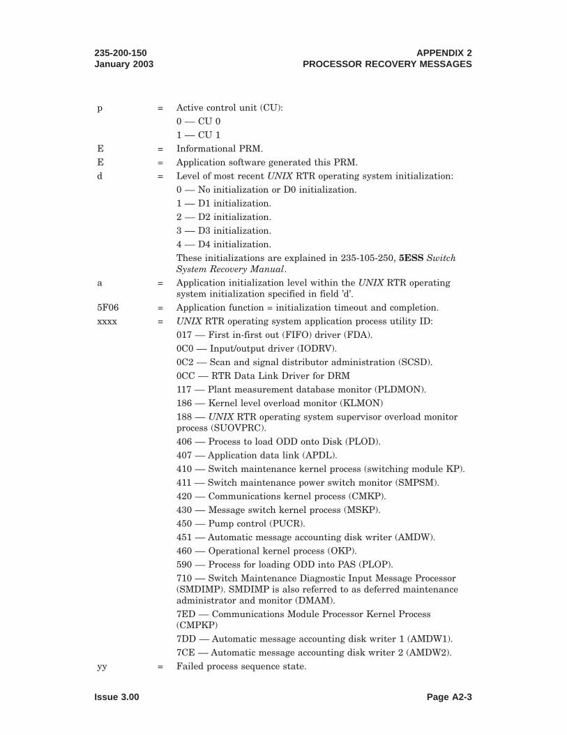
p = Active control unit (CU):0 –– CU 01 –– CU 1
E = Informational PRM.E = Application software generated this PRM.d = Level of most recent UNIX RTR operating system initialization:
0 –– No initialization or D0 initialization.1 –– D1 initialization.2 –– D2 initialization.3 –– D3 initialization.4 –– D4 initialization.These initializations are explained in 235-105-250, 5ESS SwitchSystem Recovery Manual.
a = Application initialization level within the UNIX RTR operatingsystem initialization specified in field ’d’.
5F06 = Application function = initialization timeout and completion.xxxx = UNIX RTR operating system application process utility ID:
017 –– First in-first out (FIFO) driver (FDA).0C0 –– Input/output driver (IODRV).0C2 –– Scan and signal distributor administration (SCSD).0CC –– RTR Data Link Driver for DRM117 –– Plant measurement database monitor (PLDMON).186 –– Kernel level overload monitor (KLMON)188 –– UNIX RTR operating system supervisor overload monitorprocess (SUOVPRC).406 –– Process to load ODD onto Disk (PLOD).407 –– Application data link (APDL).410 –– Switch maintenance kernel process (switching module KP).411 –– Switch maintenance power switch monitor (SMPSM).420 –– Communications kernel process (CMKP).430 –– Message switch kernel process (MSKP).450 –– Pump control (PUCR).451 –– Automatic message accounting disk writer (AMDW).460 –– Operational kernel process (OKP).590 –– Process for loading ODD into PAS (PLOP).710 –– Switch Maintenance Diagnostic Input Message Processor(SMDIMP). SMDIMP is also referred to as deferred maintenanceadministrator and monitor (DMAM).7ED –– Communications Module Processor Kernel Process(CMPKP)7DD –– Automatic message accounting disk writer 1 (AMDW1).7CE –– Automatic message accounting disk writer 2 (AMDW2).
yy = Failed process sequence state.
235-200-150January 2003
APPENDIX 2PROCESSOR RECOVERY MESSAGES
Issue 3.00 Page A2-3

00 –– Created (booted from disk).01 –– Software initialization.02 –– Hardware initialization.03 –– Communication link initialization.04 –– Enable fault recovery.05 –– Essential jobs operational.06 –– Fully operational.07 –– Aborting.
zz = Process run state.00 –– process was still performing initialization step.01 –– process had completed initialization step.02 –– process timed out.
hh hh hh = Hardware status digits. Refer to Figure A2-1 for definition of thedigits.
A2.2.1.5 Explanation
At this point, all UNIX RTR operating system application processes should havecompleted sequencing to the fully operational state. However, the specified process didnot. If this is an essential process, the HW/SW inhibits must be on. If so, noinitialization will occur; however, the system will not have essential functionality. Ifthis is a non-essential process, the HW/SW inhibit state is a don’t care; non-criticalfunctionality is lost and AIM will automatically attempt to Full Process Initialization(FPI) the specified process.
A2.2.1.6 Corrective Action
Monitor the system for lost functionality associated with the specified process. Ifsignificant periods of time (that is, several minutes) elapse without this functionality,attempt to manually recover this functionality. The situation should be dealt with asfollows: apply Master Control Center (MCC) controls (for example, inhibits); requestprocessor reconfiguration (for example, force CU/Disks); request higher manualinitializations (for example, 53); for more information, see 235-105-250, 5ESS SwitchSystem Recovery Manual or seek technical assistance .
APPENDIX 2PROCESSOR RECOVERY MESSAGES
235-200-150January 2003
Page A2-4 Issue 3.00

A2.2.2 PRM:EE 60XX-B
A2.2.2.1 PRM Format
PRM_a EEbc 60de fggg ijkk hh hh hh
A2.2.2.2 PRM Source
Application Integrity Monitor (AIM).
A2.2.2.3 Function
UNIX RTR operating system application process initialization progress.
A2.2.2.4 PRM Expansion
a = Active control unit (CU):0 –– CU 01 –– CU 1
E = Informational PRM.E = Application software generated this PRM.b = Level of most recent UNIX RTR operating system
initialization:0 –– No initialization or D0 initialization.1 –– D1 initialization.2 –– D2 initialization.3 –– D3 initialization.4 –– D4 initialization.These initializations are explained in 235-105-250, 5ESSSwitch System Recovery Manual.
c = Application initialization level within the UNIX RTROperating System initialization specified in field ’d’.
60 = Application function = DRM general initialization progress.d = Administrative Module (AM) Software initialization level:
0 –– S0 (no AW SW initialization).2 –– S2 (D1 = single process purge (SPP)) on all UNIXRTR operating system application processes).4 –– S4 (CI initialization).5 –– S5 (application full process init (FPI)).6 –– S6 (AM SW init w/o clearing phase protected data.)7 –– S7 (AM SW init with phase protected data cleared.)
e = Not significant for DRM.f = Not significant for DRM.ggg = UNIX RTR operating system application process utility ID:
017 –– First in-first out (FIFO) driver (FDA).0C0 –– Input/output driver (IODRV).0C2 –– Scan and signal distributor administration (SCSD).0CC –– RTR Data Link Driver for DRM
235-200-150January 2003
APPENDIX 2PROCESSOR RECOVERY MESSAGES
Issue 3.00 Page A2-5

117 –– Plant measurement database monitor (PLDMON).186 –– Kernel level overload monitor (KLMON)188 –– UNIX RTR operating system supervisor overloadmonitor process (SUOVPRC).406 –– Process to load ODD onto Disk (PLOD).407 –– Application data link (APDL).410 –– Switch maintenance kernel process (SMKP).411 –– Switch maintenance power switch monitor(SMPSM).420 –– Communications kernel process (CMKP).430 –– Message switch kernel process (MSKP).450 –– Pump control (PUCR).460 –– Operational Kernel Process (OKP)590 –– Process for loading ODD into PAS (PLOP).710 –– Switch Maintenance Diagnostic Input MessageProcessor (SMDIMP). SMDIMP is also referred to asdeferred maintenance administrator and monitor (DMAM).7ED –– Communications Module Processor Kernel Process(CMPKP)7DD –– Automatic Message Accounting Disk Writer 1(AMDW1).7CE –– Automatic Message Accounting Disk Writer 2(AMDW2).
i = Initialization sequence state:00 — Created (booted from disk).01 — Software initialization.02 — Hardware initialization.03 — Communication link initialization.04 — Enable fault recovery05 — Essential jobs operational.06 — Fully operational.07 — Aborting
j = Success/failure indication:0 — Initialization step completed successfully.1 — Initialization step failed.2 — Initialization step timeout.3 — Initialization step in-progress.4 — Initialization step not attempted.A — Process abort or re-initialization starting.B — Initialization step beginning (use EAI page poke42;J;50 to turn on).D — Death of child received for this process.
kk = Initialization progress points:
APPENDIX 2PROCESSOR RECOVERY MESSAGES
235-200-150January 2003
Page A2-6 Issue 3.00

00 –– Normal operation (no initialization or safe interval).01 –– AIM created.02 –– 5E critical creations requested (phase 1 creations inprogress).03 –– DB/DD initialization complete.06 –– SMKP SOFTINIT completed.07 –– MSKP SOFTINIT completed.08 –– OKP SOFTINIT completed.10 –– DRM call processing on.40 –– Call support creations requested (phase 4 creationsin progress)60 –– ULARP HM processes created.80 –– ULARP MTCE processes created.A0 –– DRM/UNIX RTR operating system non-criticalcreations requested (phase 5 creations in progress).E4 –– ULARP RC/DB processes created.F4 –– ULARP AS/TM processes created.FF –– ULARP deferred processes created (begin safeinterval).
hh hh hh = Hardware status digits. Refer to Figure A2-1 for definitionof the digits.
A2.2.2.5 Explanation
AIM prints these PRMs as the UNIX RTR operating system application processescomplete (or fail to complete) each of their required initialization sequence states.
A2.2.2.6 Corrective Action
None. These PRMs are informational only. Other failure PRMs will be printed ifoperator actions are required.
235-200-150January 2003
APPENDIX 2PROCESSOR RECOVERY MESSAGES
Issue 3.00 Page A2-7

A2.2.3 PRM:EE-CB00-B
A2.2.3.1 PRM Format
PRM_p EEda CB00 xxxx yyzz hh hh hh
A2.2.3.2 PRM Source
Application Integrity Monitor (AIM).
A2.2.3.3 Function
AIM UNIX RTR operating system application process initialization failure.
A2.2.3.4 PRM Expansion
p = Active control unit (CU):0 –– CU 01 –– CU 1
E = Informational PRM.E = Application software generated this PRM.d = Level of most recent UNIX RTR operating system
initialization:0 –– No initialization or D0 initialization.1 –– D1 initialization.2 –– D2 initialization.3 –– D3 initialization.4 –– D4 initialization.These initializations are explained in 235-105-250, 5ESSSwitch System Recovery Manual.
a = Application initialization level within the UNIX RTRoperating system initialization specified in field ’d’.
CB00 = Application function = AIM killable process initializationfailure.
xxxx = UNIX RTR operating system application process utility ID:0017 –– First in-first out (FIFO) driver (FDA).00C0 –– Input/output driver (IODRV).00C2 –– Scan and signal distributor administration(SCSD).0CC –– RTR Data Link Driver for DRM0117 –– Plant measurement database monitor (PLDMON).0186 –– Kernel level overload monitor (KLMON)0188 –– UNIX RTR operating system supervisor overloadmonitor process (SUOVPRC).0406 –– Process to load ODD onto Disk (PLOD).0407 –– Application data link (APDL).0410 –– Switch maintenance kernel process (SMKP).0411 –– Switch maintenance power switch monitor(SMPSM).
APPENDIX 2PROCESSOR RECOVERY MESSAGES
235-200-150January 2003
Page A2-8 Issue 3.00

0420 –– Communications kernel process (CMKP).0430 –– Message switch kernel process (MSKP).0450 –– Pump control (PUCR).0460 –– Operational kernel process (OKP).0590 –– Process for loading ODD into PAS (PLOP).0710 –– Switch Maintenance Diagnostic Input MessageProcessor (SMDIMP). SMDIMP is also referred to asdeferred maintenance administrator and monitor (DMAM).7ED –– Communications Module Processor Kernel Process(CMPKP)07DD –– Automatic message accounting disk writer 1(AMDW1).07CE –– Automatic message accounting disk writer 2(AMDW2).
yy = Failed process sequence state:00 –– Created (booted from disk).01 –– Software initialization.02 –– Hardware initialization.03 –– Communication link initialization.04 –– Enable fault recovery.05 –– Essential jobs operational.06 –– Fully operational.07 –– Aborting.
zz = Reason for failure.0b –– initialization time limit exceeded.0c –– initialization sequence state failed or timed out(INSEQSTFL)
hh hh hh = Hardware status digits. Refer to Figure A2-1 for definitionof the digits.
A2.2.3.5 Explanation
The AIM process produces this PRM when a killable process reports the failure of aninitialization sequence state, or when a killable process times out while initializing.
A2.2.3.6 Corrective Action
The killable process that failed should be re-initialized manually.
235-200-150January 2003
APPENDIX 2PROCESSOR RECOVERY MESSAGES
Issue 3.00 Page A2-9

A2.2.4 PRM:vE-FF03
A2.2.4.1 PRM Format
PRM_p vEda FF03 yyyy zzzz hh hh hh
A2.2.4.2 PRM Source
Application Integrity Monitor (AIM) Phase Trigger.
A2.2.4.3 Function
Failure of the Process Manager (PMGR) to create an essential process for AIM.
A2.2.4.4 PRM Expansion
p = Active control unit (CU):0 –– CU 01 –– CU 1
v = E - Administrative Module (AM) software checks areinhibited (see “Explanation,” Section A2.2.4.5).F - AM software checks allowed. A high level AMinitialization will follow immediately.
E = Application software generated this PRM.d = Level of most recent UNIX RTR operating system
initialization:0 –– No initialization or D0 initialization.1 –– D1 initialization.2 –– D2 initialization.3 –– D3 initialization.4 –– D4 initialization.These initializations are explained in 235-105-250, 5ESSSwitch System Recovery Manual.
a = Application initialization level within the UNIX RTRoperating system initialization specified in field ’d’.
FF03 = Application function = DRM phase trigger = ProcessManager (PMGR) essential process creation failure.
yyyy = UNIX RTR operating system application process utility ID:0017 –– First in-first out (FIFO) driver (FDA).00C0 –– Input/output driver (IODRV).00C2 –– Scan and signal distributor administration(SCSD).0CC –– RTR Data Link Driver for DRM0117 –– Plant measurement database monitor (PLDMON).0186 –– Kernel level overload monitor (KLMON)0410 –– Switch maintenance kernel process (SMKP).0420 –– Communications kernel process (CMKP).0430 –– Message switch kernel process (MSKP).0450 –– Pump control (PUCR).
APPENDIX 2PROCESSOR RECOVERY MESSAGES
235-200-150January 2003
Page A2-10 Issue 3.00

0455 –– Recent Change Kernel Process (RCKP).0460 –– Operational kernel process (OKP).7ED –– Communications Module Processor Kernel Process(CMPKP)
zzzz = Failed process sequence state:000A –– AIM timed out waiting for a PMGR response.yyyy –– PMGR failure code. See UNIX RTR PMGR errorcodes in Appendix C, 235-600-700, Input Messages Manual,or convert from hexadecimal to decimal and consult theREPT:PMGR output message in 235-600-750, OutputMessages Manual, for an explanation.
hh hh hh = Hardware status digits. Refer to Figure A2-1 for definitionof the digits.
A2.2.4.5 Explanation
AIM prints this PRM to report that it was unable to create an essential process.
If AM software checks are allowed, AIM will immediately trigger a high-level AMinitialization. Otherwise, no initialization will occur. However, the system may notsupport essential functionality (such as call processing, maintenance, or input/output).
A2.2.4.6 Corrective Action
If several minutes elapse without recovery, go into UNIX RTR operating systemminimum configuration. Using the process manager error code and the processidentity, check that the disk files necessary for process creation are in their correctdirectory locations and contain the correct header information.
If this fails to correct the problem, see “Analyze AM Initialization Failure,”235-105-250, 5ESS Switch System Recovery Manual.
A2.2.5 PRM:vE FF05
A2.2.5.1 PRM Format
PRM_p vEda FF05 xxxx yyzz hh hh hh
A2.2.5.2 PRM Source
Application Integrity Monitor (AIM) Phase Trigger.
A2.2.5.3 Function
AIM essential UNIX RTR operating system application process initialization failure.
A2.2.5.4 PRM Expansion
235-200-150January 2003
APPENDIX 2PROCESSOR RECOVERY MESSAGES
Issue 3.00 Page A2-11

p = Active control unit (CU):0 –– CU 01 –– CU 1
v = E - Administrative Module (AM) software checks areinhibited (see “Explanation,” Section A2.2.5.5).F - AM software checks allowed. A high level AMinitialization will follow immediately.
E = Application software generated this PRM.d = Level of most recent UNIX RTR operating system
initialization:0 –– No initialization or D0 initialization.1 –– D1 initialization.2 –– D2 initialization.3 –– D3 initialization.4 –– D4 initialization.These initializations are explained in 235-105-250, 5ESSSwitch System Recovery Manual.
a = Application initialization level within the UNIX RTRoperating system initialization specified in field ’d’.
FF05 = Application function = DRM phase trigger = essentialprocess initialization failure.
xxxx = UNIX RTR operating system application process utility ID:0017 –– First in-first out (FIFO) driver (FDA).00C0 –– Input/output driver (IODRV).00C2 –– Scan and signal distributor administration(SCSD).0CC –– RTR Data Link Driver for DRM0117 –– Plant measurement database monitor (PLDMON).0186 –– Kernel level overload monitor (KLMON)0410 –– Switch maintenance kernel process (SMKP).0420 –– Communications kernel process (CMKP).0430 –– Message switch kernel process (MSKP).0455 –– Recent Change Kernel Process (RCKP).0460 –– Operational kernel process (OKP).7ED –– Communications Module Processor Kernel Process(CMPKP)
yy = Failed process sequence state.00 –– Created (booted from disk).01 –– Software initialization.02 –– Hardware initialization.03 –– Communication link initialization.04 –– Enable fault recovery.05 –– Essential jobs operational.
APPENDIX 2PROCESSOR RECOVERY MESSAGES
235-200-150January 2003
Page A2-12 Issue 3.00

06 –– Fully operational.07 –– Aborting.
zz = Process run state.00 –– process was still performing initialization step.01 –– process had completed initialization step.02 –– process timed out.
hh hh hh = Hardware status digits. Refer to Figure A2-1 for definitionof the digits.
A2.2.5.5 Explanation
An essential application process has failed to initialize successfully by either callingINcomplete () indicating a failure or by timing out.
If AM software checks are allowed, AIM will immediately trigger a high-level AMinitialization. Otherwise, no initialization will occur. However, the system may notsupport essential functionality (such as call processing, maintenance, or input/output).
A2.2.5.6 Corrective Action
If several minutes elapse without recovery or escalation to higher levels ofinitialization, see “Analyze AM Initialization Failure,” 235-105-250, 5ESS SwitchSystem Recovery Manual.
A2.2.6 PRM:vE FF06
A2.2.6.1 PRM Format
PRM_p vEda FF06 xxxx yyzz hh hh hh
A2.2.6.2 PRM Source
Application Integrity Monitor (AIM) Phase Trigger.
A2.2.6.3 Function
AIM essential UNIX RTR operating system application process initialization timeout.
A2.2.6.4 PRM Expansion
p = Active control unit (CU):0 –– CU 01 –– CU 1
v = E - Administrative Module (AM) software checks areinhibited (see “Explanation,” Section A2.2.6.5).F - AM software checks allowed. A high level AMinitialization will follow immediately.
E = Application software generated this PRM.d = Level of most recent UNIX RTR operating system
initialization:0 –– No initialization or D0 initialization.1 –– D1 initialization.2 –– D2 initialization.3 –– D3 initialization.
235-200-150January 2003
APPENDIX 2PROCESSOR RECOVERY MESSAGES
Issue 3.00 Page A2-13

4 –– D4 initialization.These initializations are explained in 235-105-250, 5ESSSwitch System Recovery Manual.
a = Application initialization level within the UNIX RTRoperating system initialization specified in field ’d’.
FF06 = Application function = initialization timeout.xxxx = UNIX RTR operating system application process utility ID:
0017 –– First in-first out (FIFO) driver (FDA).00C0 –– Input/output driver (IODRV).00C2 –– Scan and signal distributor administration(SCSD).0CC –– RTR Data Link Driver for DRM0117 –– Plant measurement database monitor (PLDMON).0186 –– Kernel level overload monitor (KLMON)0410 –– Switch maintenance kernel process (SMKP).0420 –– Communications kernel process (CMKP).0430 –– Message switch kernel process (MSKP).0455 –– Recent Change Kernel Process (RCKP)0460 –– Operational kernel process (OKP).7ED –– Communications Module Processor Kernel Process(CMPKP)
yy = Failed process sequence state.00 –– Created (booted from disk).01 –– Software initialization.02 –– Hardware initialization.03 –– Communication link initialization.04 –– Enable fault recovery.05 –– Essential jobs operational.06 –– Fully operational.07 –– Aborting.
zz = Process run state.00 –– process was still performing initialization step.01 –– process had completed initialization step.
hh hh hh = Hardware status digits. Refer to Figure A2-1 for definitionof the digits.
A2.2.6.5 Explanation
AIM prints this PRM to report that initialization of an essential process failed tocomplete within the allotted time.
If AM software checks are allowed, AIM will immediately trigger a high-level AMinitialization. Otherwise, no initialization will occur. However, the system may notsupport essential functionality (such as call processing, maintenance, or input/output).
APPENDIX 2PROCESSOR RECOVERY MESSAGES
235-200-150January 2003
Page A2-14 Issue 3.00

A2.2.6.6 Corrective Action
If several minutes elapse without recovery or escalation to higher levels ofinitialization, see “Analyze AM Initialization Failure,” 235-105-250, 5ESS SwitchSystem Recovery Manual.
A2.2.7 PRM:VE FF1B-B
A2.2.7.1 PRM Format
PRM_p vEda FF1B wwww xyzz hh hh hh
A2.2.7.2 PRM Source
Application Integrity Monitor (AIM) Phase Trigger.
A2.2.7.3 Function
Essential UNIX RTR operating system application process full process initialization(FPI) timeout.
A2.2.7.4 PRM Expansion
235-200-150January 2003
APPENDIX 2PROCESSOR RECOVERY MESSAGES
Issue 3.00 Page A2-15

p = Active control unit (CU):0 –– CU 01 –– CU 1
v = E - Administrative Module (AM) software checks areinhibited (see “Explanation,” Section A2.2.7.5).F - AM software checks allowed. A high level AMinitialization will follow immediately.
E = Application software generated this PRM.d = Level of most recent UNIX RTR operating system
initialization:0 –– No initialization or D0 initialization.1 –– D1 initialization.2 –– D2 initialization.3 –– D3 initialization.4 –– D4 initialization.These initializations are explained in 235-105-250, 5ESSSwitch System Recovery.
a = Application initialization level within the UNIX RTRoperating system initialization specified in field ’d’.
FF1B = Application function = DRM phase trigger = essentialprocess FPI timeout.
wwww = UNIX RTR operating system application process utility ID:0017 –– First in-first out (FIFO) driver (FDA).00C0 –– Input/output driver (IODRV).00C2 –– Scan and signal distributor administration(SCSD).0CC –– RTR Data Link Driver for DRM0117 –– Plant measurement database monitor (PLDMON).0186 –– Kernel level overload monitor (KLMON)0410 –– Switch maintenance kernel process (SMKP).0420 –– Communications kernel process (CMKP).0430 –– Message switch kernel process (MSKP).0455 –– Recent Change Kernel Process (RCKP)0460 –– Operational kernel process (OKP).7ED –– Communications Module Processor Kernel Process(CMPKP)
x = Failed process sequence state.0 –– Created (booted from disk).1 –– Software initialization.2 –– Hardware initialization.3 –– Communication link initialization.4 –– Enable fault recovery.5 –– Essential jobs operational.
APPENDIX 2PROCESSOR RECOVERY MESSAGES
235-200-150January 2003
Page A2-16 Issue 3.00

6 –– Fully operational.7 –– Aborting.
y = Process run state.0 –– Running.1 –– Step done.
zz = Error code:21 — Initialization timeout
hh hh hh = Hardware status digits. Refer to Figure A2-1 for definitionof the digits.
A2.2.7.5 Explanation
AIM prints this PRM to report that it was unable to successfully complete an essentialprocess full process initialization (FPI). The FPI, also known as an S5 initialization,failed because of a timeout.
AIM will select a recovery action based on the severity of the problem, the state of thesystem, and the extent of previous recovery attempts. If the problem persists (recoverythresholds are exceeded), and AM software checks are allowed, AIM will trigger ahigh-level AM initialization. Otherwise, no initialization will occur. However, thesystem may not support essential functionality (such as call processing, maintenance,or input/output).
A2.2.7.6 Corrective Action
If several minutes elapse without recovery or escalation to higher levels ofinitialization, see “Analyze AM Initialization Failure,” 235-105-250, 5ESS SwitchSystem Recovery Manual.
A2.2.8 PRM:VE FF1F-B
A2.2.8.1 PRM Format
PRM_p vEda FF1F wwww xyzz hh hh hh
A2.2.8.2 PRM Source
Application Integrity Monitor (AIM) Phase Trigger.
A2.2.8.3 Function
UNIX RTR operating system application process Full Process Initialization (FPI)request.
A2.2.8.4 PRM Expansion
235-200-150January 2003
APPENDIX 2PROCESSOR RECOVERY MESSAGES
Issue 3.00 Page A2-17

p = Active control unit (CU):0 –– CU 01 –– CU 1
v = E - Administrative Module (AM) software checks areinhibited (see “Explanation,” Section A2.2.8.5).F - AM software checks allowed. A high level AMinitialization will follow immediately.
E = Application software generated this PRM.d = Level of most recent UNIX RTR operating system
initialization:0 –– No initialization or D0 initialization.1 –– D1 initialization.2 –– D2 initialization.3 –– D3 initialization.4 –– D4 initialization.These initializations are explained in 235-105-250, 5ESSSwitch System Recovery Manual.
a = Application initialization level within the UNIX RTRoperating system initialization specified in field ’d’.
FF1B = Application function = DRM phase trigger = FPI request.wwww = UNIX RTR operating system application process utility ID:
0017 –– First in-first out (FIFO) driver (FDA).00C0 –– Input/output driver (IODRV).00C2 –– Scan and signal distributor administration(SCSD).0CC –– RTR Data Link Driver for DRM0117 –– Plant measurement database monitor (PLDMON).0186 –– Kernel level overload monitor (KLMON)0188 –– UNIX RTR operating system supervisor overloadmonitor process (SUOVPRC).0406 –– Process to load ODD onto Disk (PLOD).0407 –– Application data link (APDL).0410 –– Switch maintenance kernel process (SMKP).0411 –– Switch maintenance power switch monitor(SMPSM).0420 –– Communications kernel process (CMKP).0430 –– Message switch kernel process (MSKP).0450 –– Pump Control (PUCR)0451 –– Automatic Message Accounting Disk Writer(AMDW).0460 –– Operational kernel process (OKP).0590 –– Process for loading ODD into PAS (PLOP).
APPENDIX 2PROCESSOR RECOVERY MESSAGES
235-200-150January 2003
Page A2-18 Issue 3.00

0710 –– Switch Maintenance Diagnostic Input MessageProcessor (SMDIMP). SMDIMP is also referred to asdeferred maintenance administrator and monitor (DMAM).7ED –– Communications Module Processor Kernel Process(CMPKP)07DD –– Automatic message accounting disk writer 1(AMDW1).07CE –– Automatic message accounting disk writer 2(AMDW2).
x = Failed process sequence state.0 –– Created (booted from disk).1 –– Software initialization.2 –– Hardware initialization.3 –– Communication link initialization.4 –– Enable fault recovery.5 –– Essential jobs operational.6 –– Fully operational.7 –– Aborting.
y = Run state.0 –– Running.1 –– Step done.
zz = Error code:20 - INcomplete () failure or timeout (s5 orlower).22 — Manual "INIT:AM,FPI" request was made. See235-600-700, Input Messages Manual.23 — Process Manager (PMGR) death of child messagereceived.24 — FPI retry requested on process that failed duringAdministrative Module (AM) initialization.
hh hh hh = Hardware status digits. Refer to Figure A2-1 for definitionof the digits.
A2.2.8.5 Explanation
AIM prints this PRM to report a request to perform a Full Process Initialization (FPI)on the specified UNIX RTR operating system application process. This level ofinitialization is also known as an S5 initialization.
If the FPI was not manually requested, AIM may select a more severe recovery actionbased on the state of the system and the extent of previous recovery attempts. If thenumber of attempted FPIs exceeds a threshold and AM software checks are allowed,AIM will trigger a high-level AM initialization. Otherwise, no initialization will occur.However, the system may not support essential functionality (such as call processing,maintenance, or input/output).
235-200-150January 2003
APPENDIX 2PROCESSOR RECOVERY MESSAGES
Issue 3.00 Page A2-19

A2.2.8.6 Corrective Action
If several minutes elapse without recovery or escalation to higher levels ofinitialization, see “Analyze AM Initialization Failure,” 235-105-250, 5ESS SwitchSystem Recovery Manual.
Digits = These digits represent the hardware status of
16-21 the PRM. All digits are active in the
transistor/transistor logic (TTL) high state.
The layout of these digits is as follows:
BIT 3 2 1 0
BIT 3: RST - Indicates that the EAI has gone through a
power-up restart. This bit will remain set
until being read by the maintenance
teletypewriter (MTTY) controller.
BIT 2: RUN - Indicates that the associated administrative
module (AM) is executing main store
instructions. This bit is defined as the
logical AND of NOT stopped (system status
register ([SSR] bit 28) and NOT halted
(SSR bit 17).
POWER
UP
(RST)
CENTER
CONTROL (CC)
UNIT RUN
CC
ACTIVE
EAI-ALL
SEEMS WELL
(ASW)
HARDWARE STATUS BITS (1 of 6)
Figure A2-1 — Hardware Status Bits (1 of 6)
APPENDIX 2PROCESSOR RECOVERY MESSAGES
235-200-150January 2003
Page A2-20 Issue 3.00

BIT 1: ACTIVE - Indicates that the associated administrative
module (AM) is on-line (SSR bit 16).
BIT 0: ASW - Indicates that the EAI thinks that all seems well
(that is, no internal faults or EAoutput errors
have been detected by EAI audit or self-test
firmware).
Digit 17 = EAI status digit.
The bits are numbered from right to left as follows:
BIT 3 2 1 0
BIT 3: PRM - Indicates that a processor recovery message
has been received from the administrative
module (AM). This bit will remain set
until being read by the MTTY controller.
BIT 2: SPR - Indicates that a processor recovery maintenance
reset function (MRF) has started. This bit
will remain set until being read by the MTTY
controller.
NEW
PRM
MRF
START
PULSE POINT
REGISTER
BIT 23
PULSE POINT
REGISTER
BIT 22
HARDWARE STATUS BITS (2 of 6)
Figure A2-1 — Hardware Status Bits (2 of 6)
235-200-150January 2003
APPENDIX 2PROCESSOR RECOVERY MESSAGES
Issue 3.00 Page A2-21
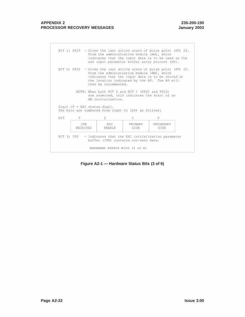
BIT 1: PP23 - Gives the last active state of pulse point (PP) 23.
From the administrative module (AM), which
indicates that the input data is to be used as the
new input parameter buffer array pointer (AP).
BIT 0: PP22 - Gives the last active state of pulse point (PP) 22.
From the administrative module (AM), which
indicates that the input data is to be stored at
the location indicated by the AP. The AP will
then be incremented.
NOTE: When both BIT 0 and BIT 1 (PP22 and PP23)
are asserted, this indicates the start of an
AM initialization.
Digit 18 = EAI status digit.
The bits are numbered from right to left as follows:
BIT 3 2 1 0
BIT 3: IPS - Indicates that the EAI initialization parameter
buffer (IPB) contains non-zero data.
IPB
RECEIVED
EAI
ENABLE
PRIMARY
DISK
SECONDARY
DISK
HARDWARE STATUS BITS (3 of 6)
Figure A2-1 — Hardware Status Bits (3 of 6)
APPENDIX 2PROCESSOR RECOVERY MESSAGES
235-200-150January 2003
Page A2-22 Issue 3.00

BIT 2: EAEN - Indicates a force function to the AM is
active or the IPB is non-zero.
BIT 1: FBDP - Indicates that a subsequent system bootstrap
will be forced from the primary boot device.
BIT 0: FBDS - Indicates that a subsequent system bootstrap
will be forced from the secondary boot device.
Digit 19 = EAI status digit.
The bits are numbered from right to left as follows:
BIT 3 2 1 0
BIT 3: FONL - Indicates the AM central control (CC) associated
with the EAI is to remain the on-line CC. The
mate CC will concurrently be forced off-line (FOFL).
BIT 2: FOFL - Indicates the AM CC associated with the EAI is
to remain the off-line CC. The mate CC will
concurrently be forced on-line (FONL).
CC
FORCED
ON-LINE
CC
FORCED
OFF-LINE
TIMER
DISABLED
CC
MRF
HARDWARE STATUS BITS (4 of 6)
Figure A2-1 — Hardware Status Bits (4 of 6)
235-200-150January 2003
APPENDIX 2PROCESSOR RECOVERY MESSAGES
Issue 3.00 Page A2-23

BIT 1: DTIM - Indicates the associated AM CC sanity timer is
disabled.
BIT 0: MRF - Indicates that a processor recovery maintenance
reset function (MRF) has started. This bit is
simular to the MRF START bit except that it
is tied to the hardware signal (it does not need
to be read to be cleared).
Digit 20 = Current status of inhibits.
The bits are numbered from right to left as follows:
BIT 3 2 1 0
BIT 3: Indicates the AM’s automatic hardware checks have been
inhibited. The specific checks inhibited are: parity checking
(on the Address Translation Bus, Instruction Bus, Source Bus,
Micro-Controller, Cache), clock checking errors, My Store
Error A, Main Store timeout error, Data Manipulation Unit
error, and Store Address Controller error.
BIT 2: Indicates that reporting of non-fatal errors has been
inhibited for all units.
HARDWARE
CHECKS
INHIBITED
UNIX SYSTEM
ERROR
INTERRUPTS
INHIBITED
CACHE
BYPASSED
(NOT USED)
SIM
INHIBITED
HARDWARE STATUS BITS (5 of 6)
Figure A2-1 — Hardware Status Bits (5 of 6)
APPENDIX 2PROCESSOR RECOVERY MESSAGES
235-200-150January 2003
Page A2-24 Issue 3.00

BIT 1: The AM’s high speed cache unit is not being used.
BIT 0: Indicates the System Integrity Monitor process (SIM)
has been prevented from initiating any action to
recover from a fault.
Digit 21 = Configuration control options.
The bits are numbered from right to left as follows:
BIT 3 2 1 0
BIT 3: Indicates the AM has been booted using the backup
root file system.
BIT 2: Indicates the AM has been booted in the minimum
configuration mode. Application software and hardware
has been disabled.
BIT 1: UNUSED (Also undefined - may be 0 or 1).
BIT 0: UNUSED (Also undefined - may be 0 or 1).
BACKUP
FILE SYSTEM
BEING USED
MINIMUM
CONFIGURATION
BEING USED
UNUSED UNUSED
HARDWARE STATUS BITS (6 of 6)
Figure A2-1 — Hardware Status Bits (6 of 6)
235-200-150January 2003
APPENDIX 2PROCESSOR RECOVERY MESSAGES
Issue 3.00 Page A2-25


A3. ADMINISTRATIVE WORKSTATION (AW) SERIAL ASYNCHRONOUS INTERFACE(SunSAI/P) BOARD GROWTH
A3.1 Introduction
The purpose of this appendix is to outline the steps necessary to install and configurethe second Serial Asynchronous Interface (SunSAI/P) board into a DRMAdministrative Workstation (AW). The second SunSAI/P board would be used for thoseoffices the require more than 6 asynchronous TTY ports.
A3.2 Procedure Overview
The first part of this procedure deals with the preconditions necessary prior toexecution. The second part of this procedure deals with the AW preparation necessaryfor the SunSAI/P growth. The third part of this procedure deals with installation ofthe new SunSAI/P hardware. The fourth part of this procedure deals with diagnosis ofthe new SunSAI/P hardware.
The following outlines the general steps executed in this procedure.
1. Meet the required preconditions.
2. Prepare the Administrative Workstation (AW).
— Backup the Administrative Workstation (AW).
— Restore all Moving Head Disks (MHDs).
— Write the Automatic Message Accounting (AMA) data from memory to disk.
— Isolate the switching module.
— Transfer the AMA data from the disk to the output medium.
3. Install serial asynchronous interface board hardware.
— Halt the AW.
— Remove power to all AW hardware units.
— Detach all cables and label them if necessary.
— Add secondary PCI card to PCI Slot 1.
— Restore power to all hardware units.
4. Diagnose the new serial asynchronous interface board hardware.
— Switch to the UNIX1 console of the AW.
— Login as root.
— Diagnose the new SunSAI/P.
— Switch over to the MCC page of the AW.
A3.2.1 Preconditions
The following preconditions must be met before executing this procedure.
1. Approximate Execution Time: 1.5 – 2 Hours
1. Registered trademark in the United States and other countries, licensed exclusively through X/OpenCompany, Limited
235-200-150January 2003
APPENDIX 3ADMINISTRATIVE WORKSTATION (AW) SERIAL
ASYNCHRONOUS INTERFACE (SunSAI/P) BOARD GROWTH
Issue 3.00 Page A3-1

2. Current Software Release: 5E14 or later .
3. Administrative Workstation: Fully Operational
4. Complete set of Generic Backup tapes for the following:
• AM Text
• AM ODD
• SM Text
• SM ODD
• Emulator and Sun OS
5. One additional Serial Asynchronous Interface Board PCI card (ED5D764-35Group 15 #X1156A)
6. One additional EIA-232 Connector Box (ED5D764-35 Group 15 #X1156A)
7. One additional EIA-232 Cable (ED5D764-35 Group 15 #X1156A)
8. Anti-static wrist strap
9. Phillips screwdriver
10. The root password for the AW which can be obtained from the 5ESS® TechnicalSupport Services (TSS) organization
11. Reference Documentation: 235-200-150, 5ESS Switch Distinctive Remote Module(DRM) User’s Guide
12. Sun2 Microsystems Reference Documentation: Netra3 t 1120/1125 ServiceManual
13. Sun Microsystems Reference Documentation: SunSAI/P User’s Guide
14. SunMicrosystems Reference Documentation: Netra T4 AC100/DC100 Service andSystem Reference Manual
A3.2.2 Administrative Workstation (AW) Preparation
1. Backup the AW, refer to “Backup Administrative Workstation OperatingSystem,” Procedure4.4.
2. Restore all Moving Head Disks (MHD).
Note: It takes about 20 minutes to restore an MHD.
a. Go to the AM, AM Peripherals page by typing and entering command 111.
b. Are any of the MHDs out of service (OOS)? If YES, continue. If NO, go tostep 3 of “Administrative Workstation (AW) Preparation,” Section A3.2.2.
c. Enter the appropriate pokes to restore all OOS MHDs. Type and entercommand 30X.
Where: X = MHD number that is OOS.
Response: RST MHD x IN PROGRESS
2. Registered trademark of Sun Microsystems, Inc.3. Trademark of Sun Microsystems, Inc.
APPENDIX 3ADMINISTRATIVE WORKSTATION (AW) SERIALASYNCHRONOUS INTERFACE (SunSAI/P) BOARD GROWTH
235-200-150January 2003
Page A3-2 Issue 3.00

d. Wait until all MHDs are fully restored to the ACT state.
Response: RST MHD x COMPLETED
Note: If any MHD cannot be restored, seek technical assistance.
3. Write the AMA data from memory to disk.
a. Enter the following input command:
WRT:AMADATA
Response: WRT AMA DATA HAS BEEN WRITTEN TO DISKREADY TO TRANSFER DATA FROM DISK TO/OUTPUT MEDIUM
4. Isolate the switching module from the AW.
a. Go to the Switching Module Inhibit and Recovery Control Page . Type andenter command 1800.
b. Set switching module manual isolation. Type and enter 403.
Response: ISOLATE? (Y/N)
c. Type and enter Y to the confirmation.
Response: SET ISOL SM=x COMPLETED
Where: x = The switching module number.
d. If the switching module cannot be isolated, seek technical assistance .
5. Transfer the AMA data from the disk to the output medium, see 235-105-210,Routine Operations and Maintenance Procedures.
A3.2.3 Serial Asynchronous Interface Board Hardware Installation ( Netra t 1120)
1. Halt the AW, refer to “Halt the Administrative Workstation,” Procedure 4.2.
2. Remove power to the system unit by locating the power switch and switching itto off .
3. Detach all cables from the AW System Unit paying particular attention whereeach cable attaches. If necessary, label each cable and where it attaches to theback of the AW System Unit.
Note: The following procedures require the use of the Sun MicrosystemsSunSAI/P User’s Guide and the Sun Microsystems Netra t 1120/1125 ServiceManual .
4. Add secondary PCI card to PCI Slot 1.
Note: Use the Installing SunSAI/P Boards procedures in the SunMicrosystems SunSAI/P User’s Guide for reference during this step.
Execute the following steps of the sub-procedure To Replace a PCI Card in theSun Microsystems Netra t 1120/1125 Service Manual
• Attach a wrist strap
• Remove the top access cover (see "Replace a DAT or CD-ROM/DVD Drive(Netra t 1120)”, Section 4.11 Step 3 and 4 of this document).
• Identifying the PCI Slot 1.
• Lower the PCI card so that it touches its associated slot on the motherboard.
235-200-150January 2003
APPENDIX 3ADMINISTRATIVE WORKSTATION (AW) SERIAL
ASYNCHRONOUS INTERFACE (SunSAI/P) BOARD GROWTH
Issue 3.00 Page A3-3

• From the two upper corners of the card, push the card straight downwardsinto the slot until it is fully seated.
• Using a No.2 Phillips-headed screwdriver, insert and tighten the screwsecuring the card bracket tab to the system chassis.
• Replace the top access cover.
5. Reattach all existing cables.
6. Attach the new EIA-232 cable to the new PCI card installed in PCI slot 1
7. Attach the new EIA-232 Connector box to the cable attached to PCI slot 1.
8. Restore power to the system unit by locating the power switch and switching itto on .
A3.2.4 Serial Asynchronous Interface Board Hardware Installation ( Netra 20)
1. Halt the AW, refer to “Halt the Administrative Workstation,” Procedure 4.2.
2. Remove power to the system unit by locating the power switch and switching itto off .
3. Detach all cables from the AW System Unit paying particular attention whereeach cable attaches. If necessary, label each cable and where it attaches to theback of the AW System Unit.
4. Add secondary PCI card to PCI Slot 1.
Note: Use the Installing SunSAI/P Boards procedures in the SunMicrosystems SunSAI/P User’s Guide for reference during this step.
Execute the following steps of the sub-procedure To Replace a PCI Card in theSun Microsystems NetraT4 AC100/DC100 Service and System ReferenceManual
• Attach a wrist strap
• Remove the top access cover (see "Replace a DAT or DVD Drive (Netra TM20)”, Section 4.12 , Step 3 and 4 of this document).
• Identifying the PCI Slot 1.
• Lower the PCI card so that it touches its associated slot on the motherboard.
• From the two upper corners of the card, push the card straight downwardsinto the slot until it is fully seated.
• Using a No.2 Phillips-headed screwdriver, insert and tighten the screwsecuring the card bracket tab to the system chassis.
• Replace the top access cover.
5. Reattach all existing cables.
6. Attach the new EIA-232 cable to the new PCI card installed in PCI slot 1
7. Attach the new EIA-232 Connector box to the cable attached to PCI slot 1.
8. Restore power to the AW units according to the procedures found in “RestorePower to Administrative Workstation Units,” Procedure 4.8.
APPENDIX 3ADMINISTRATIVE WORKSTATION (AW) SERIALASYNCHRONOUS INTERFACE (SunSAI/P) BOARD GROWTH
235-200-150January 2003
Page A3-4 Issue 3.00

When the AW starts to boot, messages similar to those shown in the followingexamples are output on the system console:
For Netra t 1120Resetting ...screen not found.Can’t open input device.Keyboard not present. Using ttya for input and output.
Sun Ultra 60 UPA/PCI (UltraSPARC-II 440 MHz), No keyboardOpenBoot 3.29, 512 MB memory installed, Serial #13079967Ethernet address 8:0:20:c7:95:9f, Host ID: 80c7959f.
Initializing MemoryRebooting with command:Boot device: /pci@1f,4000/scsi@3/disk@5,0:f File and args:SunOS Release 5.8 Version Generic-108528-13 64-bitCopyright 1983-2001 Sun Microsystems, Inc. All rights reserved.
.
.
.The system is ready.attaws console login:
For NetraResetting ...
Sun Netra T4 (UltraSPARC-III+), No keyboardCopyright 1998-2002 Sun Microsystems, Inc. All rights reserved.OpenBoot 4.5, 512 MB memory installed, Serial #51344136.Ethernet address 0:3:ba:f:73:8, Host ID: 830f7308.
Initializing MemoryRebooting with command:Boot device: /pci@8,700000/scsi@6/disk@6,0:f File and args:SunOS Release 5.8 Version Generic-108528-13 64-bitCopyright 1983-2001 Sun Microsystems, Inc. All rights reserved.
.
.
.The system is ready.attaws console login:
The AW will boot and automatically start the AM emulator.
9. Immediately halt the AM emulator using the procedurs outlined in “Halt theAdministrative Module (AM) Emulator,” Procedure 4.1.
A3.2.5 Diagnose New Serial Asynchronous Interface Board Hardware
1. Switch to the UNIX‚ console of the AW by holding down the Ctrl key andpressing Enter (not Return) on the MCC.
2. If a login prompt does not appear, press Return repeatedly until one appears.
3. At the console prompt, login as root , for example:
attaws console login: root
password: Can be obtained from 5ESS switch TSS.
235-200-150January 2003
APPENDIX 3ADMINISTRATIVE WORKSTATION (AW) SERIAL
ASYNCHRONOUS INTERFACE (SunSAI/P) BOARD GROWTH
Issue 3.00 Page A3-5

4. Execute the Sun Microsystems diagnostic of the newly installed SAI card. At the# prompt, enter the following command. The response should be as shown here.The diagnostic test takes approximately 15 seconds to complete.
/opt/SUNWvts/bin/saiptest -v -f -o dev=saip1,M=Internal,sp=b
Response:"saiptest: Started.".3 97/01/30 SMI""Baud rate = 9600, character size = 8, stop bit = 1,parity = none, control flow = rtscts""data pattern = 0xaaaaaaaa""Internal Test""Testing device /dev/sad/saip1""Testing device /dev/term/b000""Testing device /dev/term/b001""Testing device /dev/term/b002""Testing device /dev/term/b003""Testing device /dev/term/b004""Testing device /dev/term/b005""Testing device /dev/term/b006""Testing device /dev/term/b007""End saiptest test""saiptest: Stopped successfully"
5. Did all of the Sun SAI/P diagnostics complete successfully?
If YES, continue with next step .If NO, seek technical assistance .
6. Switch over to the MCC page of the AW by holding down the Ctrl key andpressing Enter (not Return) on the MCC. Wait for the MCC display to appear.
STOP. YOU HAVE COMPLETED THIS PROCEDURE.
APPENDIX 3ADMINISTRATIVE WORKSTATION (AW) SERIALASYNCHRONOUS INTERFACE (SunSAI/P) BOARD GROWTH
235-200-150January 2003
Page A3-6 Issue 3.00
A4. DRM SWITCH TO 5ESS® SWITCH CONVERSION PROCESS GUIDELINES
A4.1 Overview
To schedule a conversion of a DRM to a 5ESS switch contact Lucent WorldwideServices and request the current preconditions that must be met before performing aconversion.
235-200-150May 2004
APPENDIX 4DRM SWITCH TO 5ESS® SWITCH CONVERSION PROCESS
GUIDELINES
Issue 3.00H Page A4-1


A5. 5ESS Switch DRM Administrative Workstation NETRA1 t 1120 to NETRA 20WITH SOLARIS 8 OS CONVERSION PROCESS GUIDELINES
A5.1 Introduction
This document describes the procedure to convert the NETRA t 1120 AdministrativeWorkstation (AW) in a DRM office to the Netra 20 AW.
A5.2 Introductions
This procedure will not require any switch downtime or loss of call processing. The SMwill be in isolation from the AW for about two hours. This procedure should only beexecuted on DRM switches running the 5ESS® release [5E16.2 or later]
Note: This conversion procedure will only apply to DRM offices on the 5ESS SwitchGeneric Releases of 5E16.2 or later. Releases prior to 5E16.2 are not qualified to runon the Netra 20.
A5.3 Documentation References
The following is a list of documents to reference during the conversion process:
• “5ESS®-2000 Switch Routine Operations and Maintenance Procedures,235–105–210”
• “Administrative Workstation for 5ESS-2000 Switching System, ED5D764–30”
• “Netra T4 AC100/DC100 Installation and User’s Guide”
A5.4 UNIX2 RTR AW INSTALLATION PREREQUISITES
The following hardware and software should be available:
• Netra 20 workstation, frame-mounting hardware (if NEBS compliant). The Netra20 is expected to include:
— At least one internal SAI/P PCI Bus Adapter card with an EIA-232 SerialInterface Cable/Eight-Port Connector Box. In some offices, a second SAI/Pmay be equipped.
— One internal HSI/P PCI Bus Adapter card with a "Hydra Style" Serial PortCable
— Two internal 36GB disk drives
— One internal DAT drive
— One internal DVD drive
— The Netra 20 should be connected to a DC power source. Since the Netra 20actually uses duplex (dual bussed) DC power, new power cables should beused
Assemble the power cables as defined in section 3, subsection "DC PowerSupply/Power and Grounding Connections" from the Sun Microsystems NetraT4 AC100/DC100 Installation and User’s Guide that was provided with theNetra 20.
1. Trademark of Sun Microsystems, Inc.2. Registered trademark of The Open Group in the United States and other countries.
235-200-150May 2003
APPENDIX 55ESS Switch DRM Administrative Workstation NETRA t 1120to NETRA 20 WITH SOLARIS 8 OS CONVERSION PROCESS
GUIDELINES
Issue 3.00 Page A5-1

The Wago connectors, Strain relief housings, and Cage clamp-operating leverare all included with the Netra 20 that is shipped.
Note: The Netra 20 uses duplexed power originating on two busses andshould be connected to the "A" and "B" busses to provide true duplexed powersources.
Note: The Netra 20 uses 15A fuses as opposed to the 7A fuses the Netra t1120 uses.
Connect the new power cables to the power distribution following localpractices.
— All cabling required for the Ethernet connection to the SM.
— All cabling required for the CPI link connections to the SM.
— 120M or greater DAT tapes (to be used for backups/data transfer)
• Obtain the root password for the Netra 20 workstation from the local 5ESS CTSorganization.
• The most recent CD is required:
"3B21 Emulator and SUN OS," Solaris 8 version, for the current release
Note: Verify with 5ESS CTS that you have the latest CD-ROM.
• The following DAT tapes are recommended in case of disk corruption:
— Complete set of tapes to dead start the office in case of disk corruption. Thesewill include Generic Backup tapes for the following (may be multi-volumebackup tape):
❐ TOP tape
❐ AM Text
❐ AM ODD
❐ SM Text
❐ SM ODD
— Emulator and Sun OS backup (this tape is used to preserve any changes tothe emulator or Sun OS software applied since office bring up on thisrelease.)
— A blank DAT tape that will be used to transfer the 5ESS Generic and datafrom the Netra t 1120 to the Netra 20.
A5.5 Conversion Procedure
It is imperative that the original system be left in a state that is as functional aspossible in case a backout is required. In order to back out of this procedure at anypoint, return all cables that were moved back to the original system if it wasfunctional and reboot that system.
If office is stable enough to run the full office backup procedure, execute Step A5.5.1 tocreate a Full Backup of Office. If the office is not stable enough, go to Step A5.8.
APPENDIX 55ESS Switch DRM Administrative Workstation NETRA t 1120to NETRA 20 WITH SOLARIS 8 OS CONVERSION PROCESSGUIDELINES
235-200-150May 2003
Page A5-2 Issue 3.00

A5.5.1 Full Backup of Office
1. Execute procedure 6.17 from the 235-105-210 Switch Routine Operations andMaintenance Procedures
2. It is recommended that a full set of office backup tapes be created just prior tothe conversion. These may consist of one multi-volume backup tape for somereleases. Refer to the 235-105-210, 5ESS®-2000 Switch Routine Operations andMaintenance Procedures, “Make Full Office Backup Tape”, Section 6.23.Automated System Backup can also be used by following Section 6.41, "ScheduleBackup To Tape Using Automated System Backup Feature."
These tapes are only needed in the case that both Netra 20 disks would becomecorrupted, and it would become necessary to fall back to the Netra t 1120workstation. To deadstart an office from tape: refer to the DRM User’s Guide,Chapter 7, "System Recovery."
3. Be sure to include a backup of the Operating System and Emulator to tape. Forthe procedure to create a backup tape. Refer to the DRM User’s Guide, Section4.4, "Back Up Administrative Workstation Operating System."
A5.5.2 Restore MHDs on AW
1. At the AM, AM Peripherals page, type and enter command 111.
2. Are any of the MHDs Out Of Service (OOS)?
If YES, continue.
If NO, no further action is required.
3. Enter the appropriate pokes to restore all OOS MHDs. Type and enter command30X:
Where: X = MHD number that is OOS.
Response: RST MHD x IN PROGRESS
Where: X = is the first MHD restoral requested; the other will berestored when the first is completed.
A5.6 Write the AMA data, Isolate the SM, and Halt the Emulator
In preparation to powering down Netra t 1120 workstation, the SM should be placedin isolation. AMA Data should also be written and the Emulator halted.
To do this, execute procedure 4.1, “Halt the Administrative Module (AM) Emulator“from the DRM User’s Guide.
A5.7 Copy MHD Images and Configuration Files
1. Switch to the Sun console side of the MCC terminal. Log in as root. The rootpassword should have been obtained from the local 5ESS CTS organization.
2. Insert a blank tape Netra t 1120 Tape Drive.
3. This step will copy the MHDs (MHD 0 and MHD 2) with the office data and5ESS Generic from the Netra t 1120 to tape.
Note: Please type carefully and check the input before hitting enter for the“dd” commands. The character ‘n’ as the last character in the Output File tapedevice name of the first “dd” command specifies a non-rewinding tape write. Thesecond “dd” command will cause the tape to rewind. These commands will each
235-200-150May 2003
APPENDIX 55ESS Switch DRM Administrative Workstation NETRA t 1120to NETRA 20 WITH SOLARIS 8 OS CONVERSION PROCESS
GUIDELINES
Issue 3.00 Page A5-3

take up to 30 minutes. Wait until the first command is completed beforeentering the second command.
Execute the following commands:
/bin/dd if=/dev/rdsk/c0t0d0s7 of=/dev/rmt/0hn bs=131072
/bin/dd if=/dev/rdsk/c0t0d0s5 of=/dev/rmt/0h bs=131072
After each command completes make a note of how many records weretransferred. This information will be used later to verify that a copy of the datainto the Netra 20 partitions completed successfully.
XXXX + xxxx records in
YYYY + yyyy records out
4. Remove the DAT tape from the drive and label the tape with “5ESS GenericRelease”.
Note: The above two UNIX commands copy MHD 0 and MHD 2 respectively totape. This tape will be used in a later procedure to initialize the Netra 20 withthe 5ESS Generic and data.
5. Several system files need to be preserved across the conversion and should bewritten to a new DAT tape. To copy these files off, insert a blank tape in theNetra t 1120 tape drive and execute:
/bin/ls /etc/inet/hosts /etc/inet/netmasks /etc/hostname.qfe0/etc/defaultrouter /etc/passwd /etc/shadow /etc/nodename |/bin/cpio -ocv > /dev/rmt/0h
Remove the DAT tape from the drive and label the tape with “5ESS DRMNetwork Config Files.”
6. Execute the command and record the IP address (###.###.###.###) of the LASTentry. The IP address will be needed in Section A5.14.
grep ’connection’ /opt/ATT3bem/var/log.emul1
7. Exit from the root login by typing "exit" at the command prompt. The "login:"prompt will appear.
A5.8 Shut Down Netra t 1120 AW
The Netra t 1120 workstation will now be powered down.
1. Before removing power from the Netra t 1120, the system needs to be halted.Refer to Procedure 4.2, “Halt the Administrative Workstation”, then removepower to the system unit by locating the power switch and switching it to off.
2. Remove power from all terminals connected to the Netra t 1120. Locate thepower switches and set them to "Off".
APPENDIX 55ESS Switch DRM Administrative Workstation NETRA t 1120to NETRA 20 WITH SOLARIS 8 OS CONVERSION PROCESSGUIDELINES
235-200-150May 2003
Page A5-4 Issue 3.00

A5.9 Remove Netra t 1120 from Frame
The Netra t 1120 needs to be removed from the frame to make room for the new Netra20. Refer to Figures 2-25,"MCC Interface to AW (Netra t 1120)", 2-41, "STLWS andROP Interface(Netra t 1120)", and 2-44, “SCANS/AMA/SCCS/Optional OSS Interface(Netra t 1120)” for more information unless otherwise noted.
1. Disconnect the serial cables of the MCC terminal from the rear of the Netra t1120 workstation (connections at A and B DB-25 Serial Connectors) and labelcables "Serial A" and "Serial B".
2. Disconnect the SM Ethernet cable from the Netra t 1120 RJ45 Twisted PairEthernet (tpe) connector (hme0).
3. Disconnect the SAI cable(s) from the Netra t 1120 workstation PCI slots 1 and 2.If there are two SAI cards equipped on the Netra t 1120, take care to label thedevices properly to the corresponding primary and optional connector on Netra20 workstation.
4. Disconnect the HSI connector from the Netra t 1120 PCI slot 3.
5. Power off and disconnect the ROP connection from the DB-25 parallel connectoron the Netra t 1120.
6. Disconnect and remove the DC power cables from the Netra t 1120. Also, updatethe fuse panel label to reflect the available slot.
7. Unbolt the slide rails from the front of the frame and slide the Netra t 1120 onthe chassis slides to the front of the frame. Be careful as the Netra t 1120 isquite heavy.
A5.10 Mounting New Frame Mounted Netra 20
The Netra 20 needs to be mounted in the frame. Refer to Figures 2-26, "MCC Interfaceto AW (Netra 20)", 2-42, ”STLWS and ROP Interface (Netra 20)”, and 2-45,“SCANS/AMA/SCCS/Optional OSS Interace (Netra 20)” for more information unlessotherwise noted.
When mounting the Netra 20, the chassis slides do not need to be replaced, as theyare the same for the Netra 20 and the Netra t 1120.
1. Slide the Netra 20 on the chassis slides from the front of the frame until fullyinserted. Bolt the slide rails to the front of the frame.
2. Connect the serial cables of the MCC terminal to the rear of the Netra 20workstation (connections at A and B DB-25 Serial Connectors).
3. Connect the SM from the Ethernet cable to the Netra 20 RJ45 Twisted PairEthernet (TPE) connectors (eri0).
4. Connect the SAI cable(s) to the Netra 20 workstation PCI Slots 1 and 2. If thereare two SAI cards equipped on the Netra 20, take care to connect the devicesproperly to the corresponding primary and optional connector on Netra 20workstation.
Note: The slot numbering on the Netra 20 goes from right to left while the slotnumbering on the Netra t 1120 goes from left to right.
5. Connect the HSI connector to the Netra 20 PCI slot 3.
235-200-150May 2003
APPENDIX 55ESS Switch DRM Administrative Workstation NETRA t 1120to NETRA 20 WITH SOLARIS 8 OS CONVERSION PROCESS
GUIDELINES
Issue 3.00 Page A5-5

6. Connect the ROP connection to the DB-25 parallel connector on the Netra 20and Power up the ROP.
7. Connect the DC power to the Netra 20
Continue with step A6.11 “Power Up the Netra 20”
A5.11 Power Up the Netra 20
Power up the Netra 20, but immediately after the banner (on the MCC this will be aline of text that begins with "Sun Netra T4") is displayed, return to firmware mode(the "ok" prompt) by entering a break sequence on the MCC keyboard. For example,hold down the Control key and press F5.
Note: Note: when you power up the Netra 20, if you do not see the boot sequencebegin on the screen, you must switch to the Sun console side of the terminal byholding down the Ctrl key and pressing Enter (not Return) on the MCC.
A5.12 Boot Netra 20 OS from CD-ROM
You will now load the Netra 20 AW from the CD-ROM: "3B21E Emulator and SUNOS," Netra version, for the current release.
Refer to the DRM User’s Guide, Section 4.5.8, "Format the primary or Secondary Diskfrom a Boot CD-ROM (Netra 20).”
Please Note the Following:
1. Begin at step 2. Step 1 indicates to "Stop the AW" which has already beencompleted.
2. Format and load the Netra 20 primary disk, that is, you must execute Step 5.
A5.13 Restore the 5ESS-2000 MHDs
If the Netra t 1120 was stable at Step A5.5.1 then, execute Step A5.13.1 otherwiseexecute Step A5.13.2
A5.13.1 Stable System Restore
1. As soon as the EAI page is initialized on the screen, halt the 3B21 emulatorfrom the Emergency Action Interface (EAI) page by entering the poke 59! andresponding “y” to the verify request. You will have to time your input betweeninitializations if the system is rolling in initializations.
2. Insert the “5ESS Generic Release” DAT tape created in A6.7, Step 3 into theNetra 20 Tape Drive.
3. This step will initialize the primary MHD community (MHD 0 and MHD 2) withthe office data and 5ESS Generic from the Netra t 1120 to tape.
Note: Please type carefully and check the input before hitting enter for the“dd” commands. The character ‘n’ as the last character in the Input File tapedevice name of the first “dd” command specifies a non-rewinding tape read. Thesecond “dd” command will cause the tape to rewind. These commands will eachtake up to 20 minutes. Wait until the first command is completed beforeentering the second command.
Execute the following commands:
/bin/dd if=/dev/rmt/0hn of=/dev/rdsk/c1t0d0s7 bs=131072
/bin/dd if=/dev/rmt/0h of=/dev/rdsk/c1t0d0s5 bs=131072
APPENDIX 55ESS Switch DRM Administrative Workstation NETRA t 1120to NETRA 20 WITH SOLARIS 8 OS CONVERSION PROCESSGUIDELINES
235-200-150May 2003
Page A5-6 Issue 3.00

After each command completes, refer to the record count noted in Section A6.7.Verify that the count of records transferred from the tape with each command inthis step is exactly equal to the count of records transferred to the tape inSection A6.7. If the counts differ from the counts previously recorded, seektechnical assistance.
XXXX + xxxx records in
YYYY + yyyy records out
4. Remove DAT tape from DAT drive.
5. Insert the “5ESS DRM Network Config Files” DAT tape created in step A6.7,Step 5, into the Netra 20 Tape Drive.
6. To restore the DRM Network Configuration Files, enter the following command;
/bin/cpio –icvdu < /dev/rmt/0h
7. Remove DAT tape from DAT drive.
8. Login in to the Administration ID by typing "awadmin" at the console loginprompt.
9. From the Administrative Workstation Main Menu, select “Boot the Workstation”.Answer yes to the confirmation. If you select a task by mistake, answer no tothe confirmation.
Response:You have chosen to boot the workstation. If the Emulator is running,it must be halted before continuing. Refer to the Main Menu item ofHalt the Emulator.
Do you want to continue? (yes/no) yes
10. Wait for the boot sequence to complete and then switch back to the MCC view byholding down the Ctrl key while pressing Enter.
11. Continue with Section A5.14, “Verify the Netra 20”
A5.13.2 Unstable System Restore
If the Netra t 1120 was not stable at step A5.7, then execute this step
This procedure is done in two steps. The first step is to provision the NetworkConfiguration files and the second step is to recover the 5ESS software and databases.
A5.13.2.1 Configure DRM Network qfe0 Port
Login to the new Netra 20 as awadmin and select the option for Configure DRMNetwork qfe0 Port and follow the procedures outlined in Section A5.16
A5.13.2.2 Recover the 5ESS Software
To recover the 5ESS software, load the system following instructions from Section7.1.3, Load TOP, AM Text, and AM ODD from Multi-Volume Formatted Backup Tapes”from the DRM User’s Guide
A5.14 Verify the Netra 20
The following steps are recommended to verify the operation of the new system.
1. Ensure that call processing is operating normally. Perform test calls per localprocedures. If any problems are found, seek technical assistance .
235-200-150May 2003
APPENDIX 55ESS Switch DRM Administrative Workstation NETRA t 1120to NETRA 20 WITH SOLARIS 8 OS CONVERSION PROCESS
GUIDELINES
Issue 3.00 Page A5-7

2. Ensure that the SM is linked to the AM. This can be observed on the 111 page ofthe MCC. If the link is established, there will be an unbroken line shownconnecting the AM box and the text: SMxxx. If there is a box shown breakingthe line connecting the AM and SM, seek technical assistance.
Also, verify that cabling between the SM and the AM by executing the command“RST:MCTSI” on the standby side. If diagnostics fail on phase 9 seg 2000, thecables to SAI-1 (PCI slot 1) and SAI–0 (PCI slot 2) may be reversed. Swap thecables and re-execute the diagnostics. If there is any other failure, contact thenext level of support.
3. Check the 124 page to verify if the DCI and ASM are in service. If not, executethe following command:
ping ###.###.###.###
This is the IP address which was recorded in A6.7 Step 6. If the ping fails,contact the next level of support.
4. Ensure that all terminals and printers are operating correctly. Examples of testson terminals are:
• For each STLWS, verify that 111 page can be displayed.
• For a remote STLWS, verify that system can be accessed and that 111 pagecan be displayed.
• For the ROP, verify that OP:CLK output prints normally.
If any problems are seen and cannot be resolved by following the recommendedprocedures in the appropriate DRM User’s Guide, seek technical assistance.
5. Ensure the correct operation of the datalink applications for the office.
• Perform tests of the ability to send AMA billing data over datalinks to theremote receiver according to normal local procedures.
• Perform a test of the ability to download a file from SCANS.
• If equipped, test the operation of the TDMS/EADAS processes over thedatalinks. Refer to the DRM User’s Guide, Section 8.11.7.
• If SCC/TNM is equipped, ensure that the SCC/TNM connection to the remotemonitoring station is working normally.
A5.15 Backup the Operating System and 5ESS-2000 Software
It is recommended that a new set of full office backup tapes be created after the newsystem is verified. This should include:
• Full Office Backup
• Backup of Sun Operating System and Emulator
Note: A DDS2 (120M) or greater DAT tape is required to write on the Netra 20.The Netra 20 DDS4 DAT drive WILL NOT write to a 90M tape.
To produce a full set of office backup tapes the 5ESS®-2000 Switch RoutineOperations and Maintenance Procedures, Section 6.23, "Make Full Office BackupTape." or Section 6.41 "Schedule Backup To Tape Using Automated System BackupFeature"
APPENDIX 55ESS Switch DRM Administrative Workstation NETRA t 1120to NETRA 20 WITH SOLARIS 8 OS CONVERSION PROCESSGUIDELINES
235-200-150May 2003
Page A5-8 Issue 3.00

To produce a full set of office backup tapes the 5ESS®-2000 Switch RoutineOperations and Maintenance Procedures, Section 6.23, "Make Full Office BackupTape." or Section 6.41 "Schedule Backup To Tape Using Automated System BackupFeature"
To produce a Sun Operating System and Emulator backup tape, refer to the DRMUser’s Guide, Section 4.4, "Backup Administrative Workstation Operating System."
THIS COMPLETES THE Netra t 1120 TO Netra 20 CONVERSION PROCEDURE
235-200-150May 2003
APPENDIX 55ESS Switch DRM Administrative Workstation NETRA t 1120to NETRA 20 WITH SOLARIS 8 OS CONVERSION PROCESS
GUIDELINES
Issue 3.00 Page A5-9

A5.16 Configure the DRM Network qfe0 Port
A5.16.1 Introduction
Use this procedure to change the DRM AW qfe0 Port configuration and the DRMNetwork settings on the DRM AW.
This procedure is performed whenever DRM Network configuration settings need to bechanged.
A5.16.2 Required Information
Before beginning this procedure, you must have the new DRM Network configurationinformation, and know which DRM Network parameters are going to be updated.
Note: Changes to the DRM Network Configuration may require coordinated changeson other components of the DRM Network (ASM, DRM Gateway/Router). Failure tomake the necessary coordinated changes could result in loss of communication overthe DRM Network.
A5.16.3 Procedure
1. Verify the MCC terminal is powered on and is properly connected to theSUN3workstation.
2. If an MCC page is displayed, switch to the UNIX ® console of the AW by holdingdown the Ctrl key and pressing Enter (not Return).
3. At the login prompt, log in as awadmin.
4. From the Administrative Workstation Main Menu, select "Configure DRMNetwork qfe0 Port".
Response: Configure DRM Network qfe0 Port Sub-menu
Warning: These menu items apply to DRM Workstation configurationprocedures.1) Configure DRM qfe0 Port Name and IP Address2) Configure ASM Name and IP Address3) Configure DRM Network Number and Subnet Mask4) Configure DRM Gateway/Router IP Address5) Return to the main menu
Select task by number (1-5):
5. From the Configure DRM Network qfe0 Port Sub-menu , select the appropriatetask to update the DRM Network configuration with the new configurationvalues.
Response: The user will be prompted to enter the new configuration information,or if the user wants to use the default values for this configuration.
6. After entering the new values, press Return to get back to the Configure DRMNetwork qfe0 Port Sub-menu .
7. If performing other tasks from the Configure DRM Network qfe0 PortSub-menu, repeat steps 5 and 6. If the user has completed all necessary updates,continue with step 8.
3. Registered trademark of Sun Microsystems, Inc.
APPENDIX 55ESS Switch DRM Administrative Workstation NETRA t 1120to NETRA 20 WITH SOLARIS 8 OS CONVERSION PROCESSGUIDELINES
235-200-150May 2003
Page A5-10 Issue 3.00

8. From the Configure DRM Network qfe0 Port Sub-menu , select "Return to themain menu".
Note: The user must now reboot the DRM AW before the changes to the DRMNetwork configuration can take effect.
9. Perform Administrative Workstation Maintenance Procedure 4.1” Halt theAdministrative Module (AM) Emulator”.
10. Switch to the UNIX console of the AW by holding down the Ctrl key andpressing Enter (not Return) on the MCC.
11. From the Administrative Workstation Main Menu, select "Boot the Workstation."Answer yes to the confirmation. If you select a task by mistake, answer no tothe confirmation.
Response:You have chosen to boot the workstation. If the Emulator is running,it must be halted before continuing. Refer to the Main Menu item ofHalt the Emulator.
Do you want to continue? (yes/no) yes
12. Wait for the boot sequence to complete and then switch back to the MCC view byholding down the Ctrl Key and pressing Enter (not Return).
13. STOP. YOU HAVE COMPLETED THIS PROCEDURE
235-200-150May 2003
APPENDIX 55ESS Switch DRM Administrative Workstation NETRA t 1120to NETRA 20 WITH SOLARIS 8 OS CONVERSION PROCESS
GUIDELINES
Issue 3.00 Page A5-11


GLOSSARY
This section provides acronyms, terms, and abbreviations used in this informationproduct.
GLOSSARY
1 Packet Switching System (1PSS)A high capacity, high-reliability, X.25 packet switch produced byLucent Technologies.
3B21 Emulator Software contained in the Administrative Workstation thatemulates the operation of the 3B21D computer.
Administrative WorkstationThe DRM Sun1 workstation that provides local operations,administration, and switch maintenance.
AMA Automatic Message Accounting.
AMADNS Automatic Message Accounting Data Network Service.
AMATPS Automatic Message Accounting Teleprocessing System.
American Standard Code for Information Interexchange (ASCII)An 8-bit (seven bits plus parity) code for data transfer adoptedby the American Standards Association to achieve compatibilitybetween data devices. It is also called USASCII. There are alsoother versions.
ANSI2 An organization that develops and distributes standards for awide range of commercial products.
ASM Administrative Services Module.
ASU Alarm Status Unit.
Asynchronous A form of communications where each transmitted characterhas self-contained beginning and ending indications, so thatindividual characters can be transmitted at arbitrary times.
ATPRC Automated Translation Processing Recent Change.
Basic Rate Interface (BRI)The ISDN digital services line that combines two B channelsand one D channel on a single line. Also called the basic accessrate.
1. Registered trademark of Sun Microsystems, Inc.2. Registered trademark of American National Institute, Inc.
235-200-150May 2003
GLOSSARY
Issue 3.00 Page G-1

Basic Rate Interface (BRI) CardThe customer’s interface to the ISLU2. Three types of BRI cardsexist:
• U-Type for 2 wire
• T-Type for 4 wire.
The U and T type cards provide the customer with the 2B+Dcapabilities. The Z card performs the analog to digitalconversion similar to the CODEC function in the Analog LineUnit. These cards are mounted in groups of 32 and can bemixed, or later, interchanged (with appropriate translationupdates). The only restriction is that the T card requiresfour-wire cabling to the distributing frame.
BILLDATS 3 Billing and Data System.
Bit Contraction of Binary Digit. A single symbol, (1 or 0), that whenused in groups, represents the numbers, letters, and othersymbols of communications. Generally combined in groups of 5,8, or 16.
BITS Building Integrated Timing Source.
Bits Per Second (bps)Sometimes written as B/S or b/s. A measure of the speed withwhich data communications can move over a line. The prefixesK (for thousand) or M (for millions) are often used to representhigher speeds.
Blocking A phenomenon in a communications network where one usercannot reach another due to any one, or a combination of,network resource limitations.
Buffer Part of a communications processor or switch used to storeinformation temporarily.
Byte A sequence of successive bits (most often a group of eight)handled as a unit in computer manipulation or datatransmission.
Call A complete, 2-way interexchange of information between two ormore parties in a network. It will generally consist of a numberof sequential messages or transactions passed overcommunications circuits in each direction.
Call Request A message from a network addressable entity to the networkrequesting the establishment of a virtual call between thatnetwork addressable entity and another network addressableentity. In the specific case of an X.25 interface, a call requestpacket is sent from a data terminal equipment to a data circuitterminating equipment. This packet contains a logical channelnumber, the calling and called data terminating equipmentaddresses, and (optionally) a user facility indication and calluser data.
3. Registered trademark of AT&T Corp.
GLOSSARY 235-200-150May 2003
Page G-2 Issue 3.00

Capacity The ultimate limitation of any resource in a network to hold ormove information.
Cathode Ray Tube (CRT)Used in a generic sense to refer to data terminals that displaytransmitted and received information on a television-like screen.
CCS Traffic usage measurement equating to 100 call seconds.
CDX Compact Digital Exchange.
Channel A single, physical communications medium capable of movingintelligence from one point to another. Specific physical orlogical and electrical parameters generally define its capacity.Also see group or link.
CMP Communication Module Processor.
CNI Common Node Interface.
Coder/Decoder (CODEC)The device that turns analog signals into digital signals andvice-versa.
Communications Module 2 (CM2)The DRM’s fully duplicated time multiplexed switch which actsas a distribution hub for calls and control signals.
Concentration The effect of having more inputs than outputs for a givensystem.
CORC Customer Originated Recent Change.
CU Control Unit.
Customer-Originated Recent Changes (CORC)A customer-controlled database change caused by a change inthe lines, trunks, equipment, and/or features associated withtelephone numbers of a particular telephone office.
DAT Tape Drive Digital Audio magnetic tape format device for permanentstorage of information.
Data Circuit Terminating EquipmentThe network side of the user/network (DCE) interface. TheCCITT recommendation X.25 specifies the interface betweendata circuit terminating equipment and data terminalequipment.
Data Link A communication path directly connecting two entities. Also anensemble of terminal installations and the interconnectingnetwork operating in a particular mode that permitsinformation to be exchanged between terminal installations.
Data Link Protocol Guarantees error-free communication between two devices byensuring that sender and receiver agree on initialization, errordetection, and recovery procedures.
Dataphone 4 Digital ServiceService that provides for direct connection of digital sources to acommunications medium and, thereby, to each other.
4. Registered trademark of AT&T Corp.
235-200-150May 2003
GLOSSARY
Issue 3.00 Page G-3

Data Terminal Equipment (DTE)The user equipment that is joined to a data communicationnetwork. It could be anything from a simple terminal to a largecomputer system. The CCITT recommendation X.25 specifiesthe interface between data terminal equipment and data circuitterminating equipment.
D Channel The packet-switched channel on a DSL at 16 Kbps, or an PRI at64 Kbps that carries signaling messages and packet switcheduser data.
DCI Dual Channel Interface.
Delay As applied to packet switching, the additional time introducedby the network in delivering a packet’s worth of data comparedto the time the same information would take on a direct line.
DFC Disk File Controllers.
Digital Line and Trunk Unit 2 (DLTU2)The DRM’s DLTU2 provides the interface to digital trunks andlines such as T1, EDSL, and remote line units.
DIP Dual Inline Package.
Direct Connect PIDB (DPIDB)An interface in the ISLU2 that carries user and controlmessages from the ISLU2 to the PSU2.
Directory Routing Technique for routing information through a network based ondirectories (instructions) kept in the memory of each switch.
DRM Distinctive Remote Module.
DS1 The common terminology for T-carrier that multiplexes 24channels into a single 1.544 Mbps bit stream.
DSL Digital Subscriber Line. See Basic Rate Interface.
DSU2 Digital Service Unit 2.
EADAS Engineering and Administrative Data Acquisition System.
EAI Emergency Action Interface.
ECD Equipment Configuration Database.
EIA The Electronic Industries Association (EIA) is a tradeorganization that represents a large number of U. S. electronicmanufacturers.
Equal Access (EA) This is a point where inter-LATA customers access the exchangeto request connection across the network boundaries. This issometimes referred to as "Equal Access."
Error Detection The process of using information added to a data transmissionto detect the presence of errors in the received information.
ESS™ Switching SystemA generic term for the switching facilities in commercialnetworks utilizing computer-like processors rather than purelyelectromechanical switching relays.
GLOSSARY 235-200-150May 2003
Page G-4 Issue 3.00

Ethernet 5 A form of contention protocol being commercially deployed bythe Xerox Corporation that is used to tie facilities together inlocal geographic areas.
Extended Digital Subscriber Line (EDSL)A limited service of the Bell System Fast Select. Aninformation-bearing call request packet for a virtual call. It maybe followed by normal virtual call packet transmissions or maybe followed by an information-bearing call-clearing packet withno intervening data packet transmissions.
Flow Control The mechanism which ensures that the transmitting entity doesnot overrun the receiving entity with more data than it canaccept.
FOI Full Office Initialization.
FRAD Frame Relay Access Device.
Frame The unit of information transferred between two link levelprotocol entities. Also, a set of consecutive time slots in whichthe position of each time slot can be identified by reference to aframe alignment signal.
Gateway A node or switch that permits communication between twodissimilar networks.
Group A number of communications channels handled as a singleentity.
Group Interface Data Bus (GIDB)Connects the BRI cards to Line Group Controllers.
GUI Graphical User Interface.
Header The initial part of a data block or packet that provides basicinformation about the handling of the rest of the block.
Host The 5ESS® switch in the Switching Complex.
Host An intelligent processor or device connected to a network thatsatisfies the needs of remote users.
HSI High-Speed Interface.
Integrated Services Digital Network (ISDN)An international plan by the ITU-TS to standardize a publiccommunication network to handle circuit switched digital voice,circuit switched data, and packet switched data.
Integrated Services Line Unit 2 (ISLU2)Terminates T cars, U cards, and Z cards on the DRM.
Intelligent Terminal A data communications terminal that has sufficient intelligence(processing power) to perform fairly complex interface functionsand local formatting and processing.
Interface The place at which independent systems or devicescommunicate with each other.
Interface Units Provide the subscriber interface to the switching module
5. Registered trademark of Xerox Corporation.
235-200-150May 2003
GLOSSARY
Issue 3.00 Page G-5

International Standards Organization (ISO)An international body that standardizes goods and services. TheISO works in conjunction with the ITU-TS for standards thatimpact communications.
I/O Input/Output.
IOP Input/Output Processor.
IP Internet protocol.
ISDN Integrated Services Digital Network.
ISLU2 Integrated Services Line Unit 2.
I Series RecommendationsITU-TS recommendations on standards for ISDN services, ISDNnetworks, user-network interfaces, and under work andmaintenance principles.
ITU-TS International Telecommunication Union — TelecommunicationStandardization Sector (formerly the CCITT).
Kbps Kilobits per second; sometimes written as Cab/s.
Layer A partition of a layered architecture that performs a defined setof functions and presents those functions to the layer above viaa defined interface. A layer uses the functions of the set oflayers beneath it to perform its functions. The term layer issynonymous with the term level.
LED Light Emitting Diode.
LEN Line Equipment Number.
Level See Layer.
Limited Distance ModemA modem used to extend the range of the RS232 interface from50 to 4000 feet.
Line Group Controller (LGC)The Line Group Controller in the ISLU2 is responsible forplacing the switched information on the Line Interface DataBus (LIDB). Each LGC has two LIDBs, one to each ServiceGroup. The LGC can also provide concentration, since only 44time slots are available for switched information. The group of32 BRIs or cards is connected to a Line Group Controller (LGC)by a Duplicated Group Interface Data Bus (GIDB). In anISLU2, you can have a maximum of 16 LGCs equipped with 32BRIs (512 customer terminations).
Line Interface Data Bus (LIDB)A 32 time slot bus to connect the Line Group Controller and theCommon Data boards in an ISLU2.
Link A physical or electrical connection between two end points; forcommunications purposes, may consist of one or more channels.
GLOSSARY 235-200-150May 2003
Page G-6 Issue 3.00

Link Level The second level of a layered architecture. The purpose of thelevel is to provide the functional and procedural means toestablish, maintaining, and release data links. The level alsoprovides techniques to recover from transmission errors andother abnormal conditions such as invalid or no responses andlost of synchronization.
Local Access and Transmit Area (LATA)A defined geographical area where equal access end officesand/or access tandem offices can provide carrier access to thelocal exchange.
Local Area Network (LAN)A high-volume data transmission facility interconnecting anumber of data devices, generally within a building or acampus.
Logical Channel (LC) A point-to-point data communication path that shares a physicaltransmission medium via packet interleaved statisticalmultiplexing. In packet switching, a packet typically contains alogical channel number that identifies the packet with aparticular virtual call.
Logical Connection A communication relationship between two end points thatutilizes a virtual circuit connection between the associatedNetwork Addressable Entities (NAEs).
Loop (Local) Telephone terminology that refers to the local connectionbetween a network switch and the subscribers end instrument.
Loop (Routing) The undesirable condition in a network where traffic getsrouted in a circular path due to an anomaly of the software oraddress information.
LU Line Unit.
Main Distributing Frame (MDF)The interconnect between the outside plant facilities and theC.O. wire.
Mbps Megabytes per second.
MCC Master Control Center.
MCTSI Module Controller/Time Slot Interchanger. A device on the DRMwhich performs the time switching function.
MDF Main Distributing Frame.
Messages The logical unit of information passed between two session levelprotocol entities. A block of text that the user of acommunication network wishes to have transported as a whole.The unit of communication as seen by the user may besegmented into several packets to traverse the network. In somecircumstances, several messages can be carried in one packet.
MHD Moving Head Disk.
MHEIB Message handler Ethernet Interface Bus.
MMSU Modular Metallic Service Unit.
Modem MOdulator-DEModulator. A device that allows digital signals tobe transmitted over analog facilities.
235-200-150May 2003
GLOSSARY
Issue 3.00 Page G-7

MT Magnetic Tape.
MTTY Maintenance Teletypewriter.
Multiplexing See Logical Multiplexing.
Multi-Service Access DeviceAn access device that provides connectivity between networkelements and Network Management systems.
Network A communication system to interconnect various devices.
Network Address Coded data that identifies the location of a network addressableentity on a 1PSS.
Network Addressable Entity (NAE)Any entity directly connected to the network that supports theaccess interface protocol(s). Every network addressable entity isidentified by a network address. These network addressableentities may include such items as user computers, intelligentterminals, host (vendor) computers, Electronic SwitchingSystem switching equipment processors, certain networkfunctions, and 1PSS provided virtual terminals.
NM Network Maintenance.
Node A point of a network where various links come together;generally containing a switching element used to direct traffic.
OA&M Functions Operation, Administration, and Maintenance functions.
ODD Office Dependent Data.
OS Operation Services.
OS Operational Support.
OS Operating System.
Packet The unit of information passed between two packet levelprotocol entities. It consists of a group of bits including data andcontrol elements and routing information in a specified format.Also, a block of data handled by a network in a well definedformat including a header and having a maximum size of datafield. The unit of information passed between levels 2 and 3.
Packet Level Level 3 of the 1980 CCITT Recommendation X.25 interfacespecification. It specifies the way control information and userdata are structured into packets and the elements of procedurefor use of control information.
Packet Switch The equipment in a node that is responsible for accepting androuting packets and ensuring their correct arrival at anadjacent node.
Packet Switched DataData transmitted over a Packet Switched network.
Packet Switched Network (PSN)The interconnection of two or more packet switches to transferdata.
GLOSSARY 235-200-150May 2003
Page G-8 Issue 3.00
Packet Switching A network technique that divides user messages into relativelyshort blocks and uses geographically distributed switchingnodes, to achieve low end-to-end delay for real-time, bursty datatraffic.
PC Personal Computer.
Permanent Virtual Circuit (PVC)A virtual circuit established for the duration of an agreementbetween the subscriber and the network authority and isavailable to send packets in either direction at any time. It hasall the features of a virtual call without the call setup andrelease procedures.
PIDB A Peripheral Interface Data Bus (PIDB) is an interface in theISLU2 that provides PSU2 timing and a path to other switchingmodules and carries circuit switched information from the SG tothe TSI (MCTU3).
Protocol A set of rules for conducting interactions between two or moreentities. These rules consist of syntax (for example, headerstructure), semantics (the actions and reactions that aresupposed to occur), and timing (the relative ordering andduration of events and states).
PSTN Public Service Telephone Network.
PSU2 Packet Switch Unit 2.
PTN Packet Transport Network.
Random Routing Routing technique that moves information through the networkin a statistically random matter.
Recent Change (RC) This system function allows maintenance personnel access tothe DRM database. Recent change is used to add to or deletefrom databases and update or verify the database usingselect/mark format.
Recovery ProceduresA set of actions designed to restore a device to normaloperations.
Retrofit The ability to upgrade a DRM without impairing service to thesubscriber.
ROP Receive-Only Printer.
Routing The process of finding a suitable path to move informationthrough the network. (See Adaptive Directory Routing,Directory Routing, and Random Routing.)
Routing Table A set of instructions stored at each switch indicating the path tomove a given packet to a given destination.
RS232 (RS232C) Technical specifications set by the Electronic IndustriesAssociation (EIA) which define electrical and mechanicalinterfaces between terminals, modems, computer, andcommunications lines.
SAI Serial Asynchronous Interface.
SCANS Software Change Administration and Notification System.
235-200-150May 2003
GLOSSARY
Issue 3.00 Page G-9

SCCS Switching Control Center System.
Service Group (SG) An ISLU2 has two Service Groups (SG) that operateactive/active to switch information in the Common Data Circuits(2 per SG) to the appropriate paths. These paths are:
• The LIDBs to the LGCs.
• The PIDBs to the TSI (MCTU3).
Direct Connect PIDBs (DPIDBs) to the PSU2. The number ofPIDBs and DPIDBs is an engineered quantity, while each LGChas two LIDBs.
Service Units Provide call processing and testing functions within theswitching module.
Session A cooperative relationship between two application entitiescharacterizing the communication of data between them.
SFID Secure Feature ID.
SLC ® Carrier System The SLC carrier system provides duplex data link capabilitysimultaneously with voice usage on the existing subscriber voiceloops at data rates up to 4800 bps
SM Switching Module.
SMPU5 Switching Module Processor Unit Model 5.
SNA Systems Network Architecture (SNA) is the computer networkarchitecture developed by IBM.
STLWS Supplementary Trunk Line Workstation.
SU Software Update.
Switching Module The DRM switching module provides call-processing intelligenceand complete switching for intra-switching-module calls.
Switching Node A location in a network where switching takes place.
Synchronous A form of communications where characters or bits are sent in acontinuous stream with the beginning of one contiguous withthe end of the preceding one. Separation of one from anotherrequires the receiver to maintain synchronism to a mastertiming signal. Abbreviated Sync.
Synchronous Data Link Control (SDLC)IBM’s version of the ADCCP link control technique. Afull-duplex protocol developed by IBM.
Synchronous Time Division Multiplexing (STDM)The combining of multiple inputs into a single narrow bandtime divided output by a sampling technique that transmits allinputs including idles.
Systems Network Architecture (SNA)The computer network architecture developed by IBM.
T1 A digital transmission standard in North America that carriestraffic at the DS1 rate of 1.544 Mbps.
TAU Test Access Unit.
TDMS Traffic Data Management System.
GLOSSARY 235-200-150May 2003
Page G-10 Issue 3.00

TE Terminal Equipment.
Terminal Any device capable of sending and receiving information over acommunication channel. It is used to enter data into a computersystem and to communicate the outputs of the system to theaffected environment. Terminal devices include computers,teleprinters, special keyboards, light displays, cathode-raytubes, thermocouples, pressure gauges and otherinstrumentation, radar units, telephones, etc.
Time Slot An identifiable increment in the output of a multiplexingscheme.
TMS Time Multiplexed Switch.
Transaction A computer-based message that represents a completeunidirectional transfer of information between two points on adata network.
TRFC30 30 Minute Traffic Report.
Trunk The communications circuit between two network nodes orswitches.
TSIU Time Slot Interchange Unit.
TTYC Teletypewriter Controller.
VCDX Very Compact Digital Exchange.
Virtual Call (VC) A user facility in which a call setup procedure and a callclearing procedure determine a period of communicationbetween two data terminal equipments in which user data istransferred in the network in the packet mode of operation. Alluser data is delivered from the network in the same order inwhich it is received by the network.
Virtual Circuit A logical, rather than physical, path for a call. For example, onecall’s packetized data may be sent over different physical pathsthrough a network to one destination.
Wide Area Network (WAN)A high-volume data transmission facility interconnecting anumber of data devices, generally linking a building or acampus.
Window The major element of the flow control mechanism used toprevent the overload of a packet network. The window sizeindicates the number of packets a given user can haveoutstanding in the network at any given time.
X.25 A ITU-TS recommendation that specifies the interface betweendata terminal equipment and data circuit terminatingequipment for terminals operating in the packet mode on publicdata networks. This user to network interface includes physical,frame, and packet levels of protocol. Network services providedto the user across the X.25 interface currently include virtualcalls and permanent virtual circuits. Proposed revisions wouldprovide the transaction-oriented datagram and fast selectfeatures.
235-200-150May 2003
GLOSSARY
Issue 3.00 Page G-11

X.75 The X.75 packet switch interface is characterized as a highthroughput and a high flexibility interface. It supports virtualcall service and the X.75 utilities necessary to provide theessential facilities of X.25 as well as some additional features.
X.75 Prime A modification of X.75 by Bellcore to allow the interconnectionof dissimilar equipment in the same network.
GLOSSARY 235-200-150May 2003
Page G-12 Issue 3.00

NUMERICAL
111/112 MCC page, 2-43113 MCC page, 2-44116 MCC page, 2-451190 MCC page, 2-48124 MCC page, 2-471400 MCC page, 2-503B21 emulator, 2-413B21D Administrative Module (AM), 2-2982YD paddle board: replace, 6.6-1
A
Activate/Deactivate balance feature, 5.10-1Administrative Workstation (AW) maintenance, 4-1Administrative Workstation: backup operating system, 4.4-1Administrative Workstation: boot from alternate disk, 4.5-1Administrative Workstation: call impact, 2-5Administrative Workstation: DAT tape drive unit, 4-1Administrative Workstation: functions, 2-61Administrative Workstation: halt, 4.2-1Administrative Workstation: interface connections, 2-5Administrative Workstation: operations, 2-5Administrative Workstation: Partition and Propagate system to non—active disk,
4.5.6-1Administrative Workstation: remove power (Netra t 1120 and Netra 20), 4.7-1Administrative Workstation: replace defective hardware (Netra t 1120), 4.5.1-1Administrative Workstation: restore, 4.3-1Administrative Workstation: restore power (Netra t 1120 and Netra 20), 4.8-1Administrative Workstation: storing AMA data, 2-5Alarm Status Unit (ASU), 2-13Alarms: allow, 2-50Alarms: building power, 2-50Alarms: inhibit, 2-50Alarms: retire, 2-50All Seems Well (ASW), 2-39AM emulator: halting, 4.1-1AM initializations, A2-1AM ODD tape, 4-1AM Text tape, 4-1AMA data link growth, 8.8-1AMADNS, 2-62Architecture: DRM, 2-2Assistance, Technical, 1-4Audible ring, 2-12Automatic circuit pack Return Tag (RTAG) tool, 6.4-1Automatic Message Accounting (AMA), 2-62Automatic Message Accounting (AMA): data link, 2-45Automatic Message Accounting (AMA): direct network system, 2-45Automatic Message Accounting (AMA): teleprocessing system, 2-45AW: remove DVD drive, 4.12-1
235-200-150June 2007
INDEX
Issue 3.00P Page I-1
4.12-12-452-45
2-452-62
6.4-12-12
1-42-2
2-628.8-1
4-14-1
A2-14.1-12-39
2-502-50
2-502-50
2-132-5
20 4.8-14.3-1
20 4.7-1
2-52-5
4.2-12-61
4-12-5
4.5-14.4-1
4-15.10-1
6.6-12-2
2-412-50
2-472-48
2-45113 2-44
2-43

AW: replace CD-ROM/DVD drive, 4.11-1AW (Netra t 1120): replace DAT, 4.11-1AW (Netra20): remove DAT, 4.12-1
B
Back Up The DynaStar 500 (Base/Growth) Router Configuration File at the Host Site,3.4-1
Backout last official Software Updates (SUs), 5.6-1Backout operating system Software Update (SU), 5.8-1Backout Software Update (SU), 5.7-1Backup AW operating system, 4.4-1Balance feature: activate/deactivate, 5.10-1Basic rate interface, 2-16BITS Clock, Stratum 3, Convert, 5.11-1Boot AW from alternate disk, 4.5-1BRI, 2-16Building power alarm, 2-50
C
Cajun Switch Software Version Procedure, 3.12-1Capacities: line and trunk, 2-13Cathode ray tube, 2-19CD-ROM/DVD drive: replace, 4.11-1Centralized Telephone Communications Exchange Service (CENTREX), 2-1Circuit pack handling, 6-1Circuit pack handling: static discharges, 6-1Common Units, 2-10Communications Module 2 (CM2), 2-2ConnectVU (ATPRC) data link growth, 8.10-1Conversion procedure, Netra t 1120 to Netra 20, 1-3Corrective maintenance, 6-1Courses, training, 1-9CPI paddle board: replace, 6.7-1
D
DAT: remove, 4.12-1DAT: replace, 4.11-1DAT tape drive unit, 4-1DAT Tape Drive Unit: emergency tape ejection (Netra t 1120, Netra 20 and Netra 240),
4.21-1DAT tape drive unit: load tape, 4.19-1DAT tape drive unit: unload tape, 4.20-1Data entry functions, 2-52DDS cleaning cartridge, 4.22-1Dead start recovery, 7.1-1Dial tone, 2-12Digital Audio Tape (DAT) tape drive unit, 4-1Digital Line and Trunk Unit 2 (DLTU2), 2-12Digital Network Unit - Sonet (DNU-S), 2-12
INDEX 235-200-150June 2007
Page I-2 Issue 3.00P
2-122 2-12
4-12-12
7.1-14.22-1
2-524.20-1
4.19-14.21-1
20 2404-1
4.11-14.12-1
6.7-11-9
6-120 1-3
8.10-12 2-2
2-106-1
6-12-1
4.11-12-19
2-133.12-1
2-502-16
4.5-13 5.11-1
2-165.10-1
4.4-15.7-1
5.8-15.6-1
3.4-1
4.12-14.11-1

Digital Service Control (DSC) Unit, 2-12Digital Service Unit 3 (DSU3), 2-12Display Administration Process (DAP), 2-56Distinctive Remote Module (DRM), 2-1Document Distribution, 1-3Documentation, 1-9Documentation: CD-ROM, 2-1DRM: architecture, 2-2DRM: features, 2-62DRM: hardware, 2-3DRM: line and trunk capacities, 2-13DRM Network, 2-13DRM Network Element Software Download Procedure, 3.11-1DRM: software, 2-60DRM Switch to 5ESS Switch Conversion Process, 1-3DRM SWITCH TO 5ESS SWITCH CONVERSION PROCESS GUIDELINES, A4-1DRM NETRA t 1120 to NETRA 20 WITH SOLARIS 8 OS CONVERSION PROCESS
GUIDELINES, A5-1DVD drive: remove, 4.12-1DynaStar Router Software Version Procedure, 3.13-1
E
Emergency Action Interface (EAI), A2-1Emergency Action Interface (EAI): maintenance commands, 2-43Emergency Action Interface (EAI): menu, 2-40Emergency Action Interface (EAI) page, 2-38Emergency Action Interface (EAI): validating, 2-39Emulator: halting, 4.1-1Equipment Configuration Data (ECD), 2-60Equipment Configuration Database (ECD), 4-1Equipment Test List (ETL), 5-1Establish communication with an isolated switching module, 7.3-1Ethernet Interface Board (EIB), 2-6, 2-10
F
Features: DRM, 2-62Features not supported, 2-67Format the primary or secondary disk from a boot CD-ROM (Netra 20 or Netra 240),
4.5.8-1Format the secondary disk from a boot CD-ROM (Netra t 1120), 4.5.7-1
G
Gated Diode Crosspoints Access (GDXACC): unseating, 6.3-1Global Digital Service Function (GDSF), 2-12Growth and degrowth, 8-1
235-200-150June 2007
INDEX
Issue 3.00P Page I-3
8-12-12
6.3-1
20 2402-67
2-62
2-6 2-107.3-1
5-14-1
2-604.1-1
2-392-38
2-402-43
A2-1
3.13-14.12-1
A5-120
A4-11-3
2-603.11-1
2-132-13
2-32-62
2-22-1
1-91-3
2-12-56
3 2-12

H
Halt the Administrative Workstation, 4.2-1Halt the AM emulator, 4.1-1Hardware: DRM, 2-3Head cleaning: DAT tape drive unit, 4.22-1
I
Input/Output, 2-19Install operating system Software Update (SU), 5.5-1Integrated Digital Carrier Unit (IDCU), 2-12Integrated Services Digital Network (ISDN), 2-1, 2-3Integrated Services Test Function (ISTF), 2-12
L
Line Unit 3 (LU3), 2-12Line Unit Auto Power Recovery (LUAPR), 6.3-1Line Unit (LU) circuit packs: remove and insert, 6.3-1LNCS, 2-13Load Software Update(s) from tape, 5.2-1Load the 3B21 emulator and operating system CD-ROM and boot the AW, 7.1.1-1Load TOP, AM text, and AM ODD backup tapes, 7.1.3-1Locked-up video terminal: restore, 6.1-1Lucent network component solution, 2-13
M
Make Software Update(s) official, 5.4-1Manual recovery capabilities, 2-38Master Control Center (MCC), 2-31Master Control Center (MCC): cable connections, 2-31Master Control Center (MCC): display, 2-35Master Control Center (MCC): function keys, 2-51Master Control Center (MCC): functions, 2-35Master Control Center (MCC): index page, 2-36Master Control Center (MCC) terminal settings, A1-3MCC access growth: dial-up modem, 8.5-1MCC Display: AM, AM peripherals, 2-43MCC Display: DCI/ASM Status, 2-47MCC Display: MCTSI Status, 2-48MCC Display: Miscellaneous Status, 2-45MCC Display: Operations systems links, 2-44MCC Display: SM/BLDG/PWR Alarm, 2-50MCC Function Key: alarm release, 2-52MCC Function Key: ALM RLS, 2-51MCC Function Key: CMD/MSG, 2-51MCC Function Key: EMER DISP, 2-51MCC Function Key: emergency action display, 2-52MCC Function Key: input command or message, 2-52MCC Function Key: NORM DISP, 2-51
INDEX 235-200-150June 2007
Page I-4 Issue 3.00P
2-512-52
2-522-51
2-512-51
2-522-50
2-442-45
2-482-47
2-438.5-1
A1-32-36
2-352-51
2-352-31
2-312-38
5.4-1
2-136.1-1
5.2-12-13
6.3-16.3-1
3 2-12
2-122-1 2-3
2-125.5-1
2-19
4.22-12-3
4.1-14.2-1

MCC Function Key: normal display, 2-52Modular Metallic Service Unit (MMSU), 2-12Module Controller/Time Slot Interchange (MCTSI), 2-10Mount tape on tape drive unit, 4.19-1
O
Office Record Printer baud rate: update, 8.14.1-1Office Record Printer degrowth, 8.21-1Office Record Printer growth, 8.14-1Operating system: backup, 4.4-1Operational Support Systems (OSSs), 2-19Operator Services Position System (OSPS), 2-3Optional terminal interfaces, 2-19
P
Password protection, 2-60Peripheral Units (PUs), 2-12Plain Old Telephone Service (POTS), 2-1, 2-3Post AM recovery cleanup, 7.2-1PRI, 2-16Primary rate interface, 2-16PRM, 1-3PRM - 60XX, A2-5PRM - CB00, A2-8PRM - FF03, A2-10PRM - FF05, A2-11PRM - FF06, A2-13PRM - FF1B-B, A2-15PRM - FF1F-B, A2-17PRM:EE 5F06, A2-2Processor recovery messages, 1-3Processor Recovery Messages (PRMs), A2-25
R
RC/V terminal degrowth, 8.18-1RC/V terminal growth, 8.4-1Receive-Only Printer (ROP), 2-19, 2-35, 2-53Recent Change (RC/V) terminal, 2-56Recorded Announcement Function (RAF), 2-12Recover from BROOT configuration, 7.2.4-1Remote Integrated Services Line Unit (RISLU), 2-13Remote Sun Console access growth: dial-up modem, 8.6-1Replace a Defective Primary Disk (Netra 20), 4.5.3-1Replace a Defective Secondary Disk (Netra 20), 4.5.2-1Retrofit, 2-62Retrofit: generic, 2-46Revenue Accounting Office (RAO), 2-45RMAS data link growth, 8.12-1Routine maintenance, 5-1
235-200-150June 2007
INDEX
Issue 3.00P Page I-5
5-18.12-1
2-452-46
2-6220
208.6-1
2-13
2-122-56
2-19 2-35 2-538.4-1
8.18-1
A2-251-3
A2-2A2-17A2-15
A2-13A2-11A2-10A2-8A2-5
1-32-16
2-167.2-1
2-1 2-32-12
2-60
2-192-3
2-194.4-1
8.14-18.21-1
4.19-12-10
2-12

Rural Electrification Administration (REA), 2-1
S
Sanity Timer: disable, 2-38SCANS data link growth, 8.7-1SCC data link degrowth, 8.19-1SCC data link growth, 3.8-1, 8.9-1Signaling System 7 (SS7), 2-62Software Change Administration and Notification System (SCANS) data link, 2-57Software: DRM, 2-60Software release retrofit, 2-62Software release update, 2-63Software: switching module, 2-62Software Updates (SUs), 2-57Software Updates (SUs): backout, 5.7-1, 5.8-1Software Updates (SUs): backout last, 5.6-1Software Updates (SUs): install, 5.5-1Software updates (SUs): load from SCANS, 5.1-1Software Updates (SUs): load from tape, 5.2-1Software Updates (SUs): make official, 5.4-1Static discharges, 6-1STLWS degrowth, 8.17-1STLWS growth, 8.3-1Stratum 3 BITS Clock, Convert, 5.11-1SUN OS tape, 4-1Sun Console terminal settings, A1-3Supplemental Trunk and Line Work Station (STLWS), 2-56Switching module, 2-2, 2-3Switching module memory errors: analyze and clear non-diagnosable, 6.5-1Switching Module ODD tape, 4-1Switching module software, 2-62Switching Module Text tape, 4-1System: boot, 2-38System recovery, 7-1System recovery: Post AM recovery cleanup, 7.2-1
T
T1/E1 external reference timing, 2-12TDMS/EADAS data link growth, 8.11-1Technical Assistance, 1-4Technical Support Services (TSS), 1-4Terminal interface devices, 2-21Terminal software initialization, 6.2-1Tone decoding, 2-12Tone generation, 2-12TOP tape, 4-1Traffic Printer degrowth, 8.20-1Traffic Printer growth, 8.13-1Training courses, 1-9TSS, 1-4
INDEX 235-200-150June 2007
Page I-6 Issue 3.00P
1-41-9
8.13-18.20-1
4-12-12
2-126.2-1
2-211-4
1-48.11-12-12
7.2-17-1
2-384-1
2-624-1
6.5-12-2 2-3
2-56A1-3
4-13 5.11-1
8.3-18.17-16-1
5.4-15.2-1
5.1-15.5-1
5.6-15.7-1 5.8-1
2-572-62
2-632-62
2-602-57
2-623.8-1 8.9-1
8.19-18.7-1
2-38

U
UNIX Operating System, 2-61UNIX RTR operating system, A2-2User Comments, 1-3
V
Video Display Terminal (VDT), 2-35Video terminal: restore locked-up, 6.1-1Virtual TTY controller degrowth, 8.15-1Virtual TTY controller growth, 8.2-1Virtual TTY degrowth, 8.16-1Virtual TTY growth, 8.1-1Voice Path Assurance (VPA), 2-12
235-200-150June 2007
INDEX
Issue 3.00P Page I-7
2-128.1-1
8.16-18.2-1
8.15-16.1-1
2-35
1-3A2-2
2-61
