5z373, - superfund records collections | us … · draft final report september 1986* ......
TRANSCRIPT

5Z373,ORIGINAL(Red)
GCA-WR-5UB9Prepared' for
NUS Corporation, Pittsburgh, PAand the
U.S. Environmental Protection Agency, Region III
NUS Project No. S785.01EPA Work Assignment No. 76-3L24Prime Contract No. 68-01-6699GCA Subcontract No. Z0830913
NUS Work Assignment ManagerRaymond Wattras
EPA.Work Assignment ManagerStephanie Del Re
FEASIBILITY STUDYSALTVILLE WASTE DISPOSAL SITE,
SMYTH COUNTY, VIRGINIA
Draft Final Report
September 1986*
Prepared by
GCA Technology Division, Inc.Bedford, Massachusetts 01730
andMetcalf & Eddy Inc.
Wakefield, Massachusetts 01888
*SEE COMMENT ON NEXT PAGE

DISCLAIMER
This Draft Final Report was furnished to the Environmental ProtectionAgency by the GCA Technology Division, Inc., Bedford, Massachusetts 01730, infulfillment of NUS Project No. S785.01, EPA Work Assignment No. 76-3L24. Theopinions, findings, and conclusions expressed are those of the authors and notnecessarily those of the Environmental Protection Agency or the cooperatingagencies. Mention of company or product names is not to be considered as anendorsement by the Environmental Protection Agency.
*COMMENT
THIS FEASIBILITY STUDY PRESENTS AN ANALYSIS TO DETERMINE THE MOSTCOST-EFFECTIVE REMEDIAL ALTERNATIVE APPLICABLE TO THE SALTVILLE WASTE DISPOSALSITE. THIS ANALYSIS WAS BASED PARTIALLY UPON THOSE DATA AND CONCLUSIONSDEVELOPED IN THE SEPTEMBER 1986 RISK ASSESSMENT (RA) CONDUCTED BY GCA.
AS NOTED IN THE SALTVILLE RA, FISH AND SEDIMENT SAMPLING RESULTS FOR THEPERIODS OF AUGUST 1984-1985 AND JULY/AUGUST 1986 WERE NOT AVAILABLE AND/ORANALYZED IN THE SEPTEMBER 1986 REPORT. THEREFORE, THE CONCLUSIONS ABOUT THERISKS TO PUBLIC HEALTH AND THE ENVIRONMENT POSED BY/FROM THE SALTVILLE SITEMUST BE REEXAMINED PRIOR TO FINALIZING SELECTION OF THE ALTERNATIVE(S) MOSTAPPLICABLE TO REMEDIATION AT THE SALTVILLE SITE.

ORIGINAL(Red)
CONTENTS
Figures ............................... ivTables ................................ v
I. Introduction ......................... 1-1Scope of Work Effort ................... 1-1Project Approach ..................... 1-2Site Background and Definitions ............. 1-3
2. Establishment of Remedial Response Objectives ......... 2-1General Considerations .................. 2-1Institutional Scoping of Response Actions for theSaltville Waste Disposal Site ............. 2-3
Risk Assessment Summary ................. 2-22Remedial Response Objectives for the Saltville Site . . . 2-24
3. Identification of General Response Actions andScreening of Remedial Technologies ............. 3-1
Screening of Remedial Technologies ............ 3-1Summary of Remedial Technology Screening for theSaltville Waste Disposal Site ............. 3-73
4. Formulation and Screening of Remedial Alternatives ...... 4-1NCP Requirements ..................... 4-1Assumptions ....................... 4-3Remedial Alternatives Formulation ............ 4-Initial Screening of Remedial Alternatives ........ 4-iSummary ......................... 4-3
5. Detailed Analysis of Remedial Alternatives for theSaltville Site ..................... 3-1
Detailed Specification of Remedial Alternatives forthe Saltville Site ................... 3-2
Technical Feasibility of Remedial Alternatives ...... 5-21Public Health Analysis of Remedial Alternatives ..... 3-37Environmental Evaluation of Remedial Alternatives .... 5-51Institutional Analysis of Remedial Alternatives ..... 3-57Cost Analysis of Remedial Alternatives .......... 5-68
References .............................. 5-76Appendices
1. Waste Pond 5 Settlement/Stability Analysis .......... 6-22. Saltville Waste Pond No. 5 Treatment System Design
Calculations ......................... 6-63. Metcalf & Eddy Site Visit Report (July 15, 1986) ....... 6-474. List of Treatment Systems Vendors and Literature Review .... 6-555. Dike Stability Analysis .................... 6-596. Detailed Component Costs of Remedial Action Alternatives
For the Saltville Site ................... b-t>4
iii
A'R30.Ql*72

FIGURES
Number Page
I. I Partial map of Virginia showing the location ofSaltville, VA ........................ 1-6
1.2 Topographic map identifying the area designated as theSaltville Waste Disposal Site ................ 1-7
4. I Sketch of existing and proposed upgraded surface waterrunon controls at the Saltville site ............ 4-7
4.2 Wastewater treatment conceptualization ............ 4-14
4.3 Wastewater treatment system schematic ............. 4-ll
5.1 Conceptual design of surface water runon controlsystem upgrade ....................... 5-6
5.2 Typical drainage channel cross-section ............ 5-1 1
5.3 Cross-sectional view of proposed cap overlyingwaste pond No. 5 ...................... 3-13
5.4 Conceptual design of surface water conveyance systemoverlying the proposed cap for waste pond Mo. 5 ....... 5-13
5.5 Proposed sodium sulfyhdrate precipitation treatmentsystem for waste pond No. 5................. 5-17
,5.6 Proposed iron sulfide "Sulfex" precipitation treatmentsystem for waste pond No. 5................. i-ld
5.7 Proposed carbon treatment system for waste pond No. 5 ..... 5-19
5.8 Proposed treatment plant location ............... 5-22
IV
flR300473
ORIGINAL(Red)
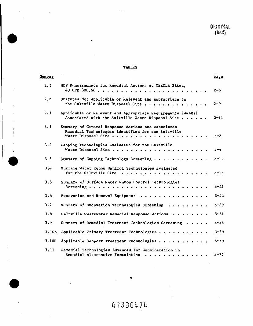
TABLES
Number
2.1 NCP Requirements for Remedial Actions at CERCLA Sites,40 CFR 300.68 ........................ 2-fa
2.2 Statutes Not Applicable or Relevant and Appropriate tothe Saltville Waste Disposal Site .............. 2-9
2.3 Applicable or Relevant and Appropriate Requirements (ARARs)Associated with the Saltville Waste Disposal Site ...... 2-11
3.1 Summary of General Response Actions and AssociatedRemedial Technologies Identified for the SaltvilleWaste Disposal Site ..................... 3-2
3.2 Capping Technologies Evaluated for the SaltvilleWaste Disposal Site ..................... 3-4
3.3 Summary of Capping Technology Screening ............ 3-12
3.4 Surface Water Runon Control Technologies Evaluatedfor the Saltville Site ................... 3-13
3.5 Summary of Surface Water Runon Control TechnologiesScreening .......................... 3-21
3.6 Excavation and Removal Equipment ............... 3-22
3.7 Summary of Excavation Technologies Screening ......... 3-29
3.8 Saltville Wastewater Remedial Response Actions ........ 3-31
3.9 Summary of Remedial Treatment Technologies Screening ..... 3-33
3.10A Applicable Primary Treatment Technologies ........... 3-59
3.10B Applicable Support Treatment Technologies ........... 3-jy
3.11 Remedial Technologies Advanced for Consideration inRemedial Alternative Formulation .............. 3-77

TABLES (continued)
4.1 Remedial Alternative Components Identified forthe Saltville Site ..................... 4-6
4.2 Formulation of Surface Water Runon Control RemedialAlternative Components ................... 4-9
4.3 Remedial Alternatives Formulated for the SaltvilleWaste Disposal Site ..................... 4-19
4.4 Summary of Effectivess Evaluation of Those RemedialAlternatives Formulated for the Saltville WasteDisposal Site ........................ 4-28
4.5 Order of Magnitude Cost Estimates of Those RemedialAlternatives Formulated for the Saltville WasteDisposal Site ........................ 4-29
4.6 Candidate Remedial Alternatives for Detailed Analysis ..... 4-31
5. I Hydro logic Analysis of Runon Contribution to Pond 5From Remaining Uncontrolled Areas .............. 5-7
5.2 Treatment Alternatives/Alternative Components .Evaluated for the Saltville Site .............. 3-16
5.3 Estimated Sludge Quantities Generated by Each RemedialTreatment Alternative/Alternative Component ......... 5-2U
5.4 Truck Accident Rates ..................... 5-44
5.5 Costs of Remedial Alternatives Proposed for theSaltville Site ....................... 5-71
5.6 Sensitivity Analysis of Total Present Worth Cost ofRemedial Alternatives .................... 5-74
VI
AR300U75

ORIGINAL(Red)
SECTION I
INTRODUCTION
SCOPE OF WORK EFFORT
This document was prepared by GCA Technology Division, Inc. and Metcalf &Eddy, Inc. as Phase II of a two-phase Risk Assessment (RA) and FeasibilityStudy (FS) being performed for the Saltville Waste Disposal Site located inSaltville, VA.
More specifically, GCA Technology Division, Inc. (under SubcontractNo. Z0830913 to NUS Corporation) recently issued the Revised Draft FinalReport entitled "Risk Assessment - Saltville Waste Disposal Site, Smyth
County, Virginia" in September 1986. The objective of the RA (Phase I) was todocument the nature and extent of the hazardous substances at and surroundingthe Saltville site, the environmental fate and transport of these substancesand the extent of any public health and environmental impacts associated withthese present conditions.
Based upon the risks identified in the RA (both on the environment andthe public health), the second phase of this study was initiated andcompleted. The objectives of the Feasibility Study (Phase II), as stated inthe NUS Corporation prepared Draft Work Plan of November 1984, were as follows;
(I) To determine the remedial measures which may be necessary tomitigate a potential threat (if present) from those contaminants insurface water, soils, groundwater, and biota (fish).
(2) To identify a list of potential remedial actions for the SaltvilleWaste Disposal Site in conjunction with the remedial objectives andcriteria selected, including a "No Action" alternative.
(3) Tp evaluate the appropriateness and applicability of potentialremedial actions. Factors to be included in this analysis mayinclude: cost, reliability, level of cleanup achievable,constructability, protection of public health, and institutionalconstraints.
1-1

(4) To prepare a conceptual design of the alternative selected by EPAand other regulatory agencies.
This Draft Final Feasibility Study represents the completion of Phase IIof this overall work effort. It should be noted, however, that the fourthobjective stated above has not been initiated to date and is, therefore, not
included in this Draft Final FS Report, pending negotiations and eventualselection of the final remedial action to be implemented at the SaltvilleWaste Disposal Site.
PROJECT APPROACH
The basic approach utilized in the conduct of the Saltville WasteDisposal Site Feasibility Study was essentially that prescribed in the NUSprepared Draft Work Plan. This technical approach, as briefly restated below,
mainly consisted of four (4) steps:
Identification of Alternatives
Based on the results displayed in the existing data, the risk assessment,and considerations of site conditions, a preliminary list of remedialalternatives was identified. This process entailed, first, a selection ofthose criteria to be used for evaluating the remedial measures, and second, anidentification of the proposed remedial measures.
Initially, the objectives of the site remediation were identified.Following a definition of these objectives, and the development of selectioncriteria, a preliminary list of remedial technologies was identified and then
screened. Based upon these results, a preliminary list of remedialalternatives was developed identifying the degree and nature of contaminationand the objectives established for site remediation.
Initial Screening of Alternatives
Those preliminary remedial alternatives identified were then screened toidentify those measures which were not appropriate for further detailedevaluation. Evaluation criteria for the initial screening included, but wasnot be limited to, the following:
1-2
.flR300i*77

• The cost for implementation, operation and maintenance, andmonitoring.
• The environmental impacts created by implementation of the remedialmeasure.
• The degree of environmental protection that the remedial measure canprovide.
• The feasibility of implementing the remedial measure and itsreliability.
Detailed Evaluation of Alternatives
Those alternatives selected as potential remedial actions at theSaltville Waste Disposal Site were then subjected to a detailed evaluation to
determine the most cost-effective and environmentally sound remedial action.Initially, sufficient data was developed regarding each of the prescreenedalternatives, so that each could be adequately evaluated and compared. Thedetailed development of each alternative included the following:
• A description of the remedial alternative.
• Degree of remediation accomplished by the remedial actions,
• Special engineering considerations required for projectimplementation.
• Environmental and health impacts created by the remedial alternativeand methods necessary to mitigate adverse effects.
• Operation, maintenance, and monitoring requirements.
• Offsite disposal and transportation needs.
• Temporary storage requirements.
• Safety requirements for remedial implementation.
Once each alternative was developed, the detailed evaluation of eachalternative's ability to meet those objectives identified for remediation at
the Saltville Waste Disposal Site was completed. The potential remedialalternatives were then evaluated according to the following criteria:
1-3
flR300ii78

• Cost
« Reliability
• Implementability
• Safety Requirements
« Operating and Maintenance (O&M) and Monitoring Requirements
9 Environmental Impact and Public Health Risk Assessment
Based on the evaluation of alternatives, EPA and other State agencieswill select a recommended alternative. Selection of this alternative will bebased on the perceived performance of the alternative with respect to theevaluation criteria previously listed.
Final Report
A final report, which summarizes all activities conducted during the FS,was prepared and is submitted to the EPA for review, as contained herein.This report summarizes the site background containing the findings of previousinvestigations, summarizes the remedial action evaluation process, and 'presents the justification for selection of the chosen remedial action. This >report also contains those appendices that facilitate further puolic review or iaid In subsequent procurement and contracting.
In addition to the above specified approach, and in order to t>ei
consistent with the requirements of the National Oil and Hazardous Substances iPollution Contingency Plan (NCP; 40 CFR Part 300; November 1985) and the U.S.2PA Guidance on Feasibility Studies under CERCLA (EPA/540/G-85/003; June ly«5), !the GCA/M&E project team performed an "Institutional Scoping of Response ''Actions for the Saltville Waste Disposal Site". This scoping exercise was i
iundertaken prior to the above four steps so as to provide a preliminary jfiptHtmin.-Jtion of the extent to which Federal environmental and public healthrequirements were applicable or relevant and appropriate to the Saltville site jand the extent to which other Federal criteria, advisories, and guidance andStat« of Virginia standards are to be used in developing remedial actions for jth« site. The results of this initial analysis is provided in Section <d ot
1-4

ORIGINAL(Red)
this report, along with a summary of the conclusions drawn from the SaltvilleWaste Disposal Site Risk Assessment and the remedial response objectivesestablished for this site.
The remaining portion of this section contains a brief summary of thesite background, including a discussion of those remedial actions undertakenat the Saltville site to date, and a definition of several key terms used in
the preparation of this Feasibility Study. Finally, Sections 3 through 5 ofthis report consists of those first three steps outlined in the NUS-developedtechnical approach, as described previously.
SITE BACKGROUND AND DEFINITIONS
This subsection briefly summarizes the Saltville Waste Disposal Site'sbackground/history as it relates to the Saltville FS. The reader is directedtowards the Remedial Action Master Plan (RAMP), dated June 1984 - prepared byNUS Corporation, and the Saltville Site: Risk Assessment, dated September1986 - prepared by GCA Technology Division, Inc., for more detailedinformation relative to previous site investigations (including the numerousanalytical results available) and/or a more in-depth historical perspective ofthe site.
Site Description/History
The Saltville Waste Disposal Site is located between the town of
Saltville and the community of Aliison Gap in western Smyth County, Virginia,which is located in southwestern Virginia. The Jefferson National Forest islocated approximately 1/2 mile north of the site, and the North Fork of theHolston River (NFHR) forms the southern boundary of the site. Map coordinatesfor the site location are 36° 53' north latitude and 81° 47" west longitude.The site location is shown in Figures I.1 and 1.2.
In 1892, Mathieson Alkali Works acquired property in Saltville,
Virginia. Construction began on an alkali plant the next year. In 1931Mathieson built a dry ice plant, and in 1950 a chlor-alkali plant. In thelate 1920's, the approximately 80-acre Waste Pond 5 was built to dispose of
the waste sludges generated from the various plant processes. In the
1-5

J2n
s.a «rft-• tfl
14-4O
O
I! ̂ 1 1 5 - «liBlflM .5II tit! 1? §s s £ 8 1 a i J=
l l00s
SO Oi 1
5 5 s 1I ?| 51 H 1 e• sf s,= $1 E ,_ife S* Si 3l ^ «
•*! •« i« < 'u
|l s s a i i< £ (A ir ul ul inJi • I a. u. ec
W W Wl
oo
1-6

ORIGINAL(Red)
SALTVILLE WASTEDISPOSAL SITE
SCALE, FEETQUADRANGLE LOCATION
Figure 1.2. Topographic map identifying the area designated asthe Saltville Waste Disposal Site.
1-7

operation of the electrolytic chlorine and caustic soda plant, one of the
electrodes used contained mercury which leaked into the sludge and onto theplant grounds. This plant operated from 1950 to 1970, losing approximately ,
I100 Ibs./day of mercury. Mathieson Chemical Corporation merged with Oliu J
Corporation in 1954.After thrt Minimata Bay poisoning incident in 1969 brought attention to j
mercury contamination in the environment, sampling revealed a severe mercurycontamination at the Saltville site and in the NFHR. As a result of a fish 'and sediment sampling effort, both the States of Virginia and Tennessee placed
a complete ban on fishing in the North Fork of the Holston River. Later, both j
bans were reduced to cover consumption of fish only. • 'Subsequently, Olin modified its operating procedures to cut mercury |
losses to 1/4 Ib./day. In 1970, the Virginia State Water Control iBoard (VSWCB) adopted a total dissolved solids (TDS) stream standard of500 rag/I for the NFHR, which Olin was unable to meet near their plant. HS a 'result of this, as well as increased operating costs, Olin decided to close
iits Saltville operations. The final shutdown occurred in 1972. By that time, {
an estimated 110 tons of mercury had been released into the plant site area,
and an additional 50 tons were in Waste Pond 5. The chlor-alkali plant wasdemolished in 1973.
Since 1970, fish and sediment sampling in the North Fork of the Holston
River has been performed every year. This sampling work has identifiedmercurv concentrations in the sediments near the site and downstream, and at
concentrations exceeding allowable limits in fish tissues. In 1978, a task
force was formed by concerned agencies including the Virginia State WaterControl Board, Virginia Attorney General's Office, Tennessee and VirginiaStat« Departments of Public Health, the Tennesse Valley Authority, and the
USEPA. This task force has been involved in numerous negotiations with OlinCorporation concerning possible cleanup measures to solve or at least lessen
the mercury contamination problem in the NFHR. In December 1982, the site was
proposed to be listed on the National Priorities List (NPL), and is currentlylisted as NPL site No. 518 of the 786 current and proposed sites.
Several remedial-type measures have been undertaken by Olin over the past
several years at the Saltville site. Specifically, Olin has placed rip-rap
a long the riverbanks to stop dike erosion and has installed a western upland
1-8
flR30.0t#.83

RIGIKAL(Red)
diversion ditch around Waste Pond 5 to lessen surface water runon flow intothe pond. Also, Olin diverted a 1300 foot section of the NFHR and dredged
1000 feet of the exposed, contaminated river bed near the former chlor-alkaliplant. Mercury was then extracted from the dredged sediments. The sediments
were spread over the former plant site, and encapsulated; then the site •was capped. This work was done as part of a Special Order entered into byOlin and the VSWCB, details of which are provided in Section 2 of thisreport.
Definitions
As briefly described above, the Saltville Waste Disposal Site (or source)can be defined as consisting of the following three areas:
(1) the former chlor-alkali plant,
(2) Waste Pond no. 5, and
(3) Waste Pond no.6.
Although no mercury contaminated wastes have ever been reportedly dumped intothe approximately 45-acre Waste Pond no.6, structural components of the formerchlor-alkali plant site were buried at the eastern edge of the pond. Also,Waste Pond 6 was reportedly used to catch the overflow from Waste Pond 5. Allthree areas are located along the north bank of the North Fork of the HolstonRiver.
Those areas not included in the above definition were considered, in this
report, as Offsite or management of migration areas. As such, these areasbasically include the entire reach of the North Fork of the Holston River fromthe former chlor-alkali plant (river mile 83) downstream to its confluencewith the South Fork of the Holston River in Tennessee. This reach of river isthat area where mercury contamination from the Saltville Waste Disposal Sitehas migrated, resulting in mercury contaminated river sediments.
1-9

ORIGINAL(Red)
SECTION 2
ESTABLISHMENT OF REMEDIAL RESPONSE OBJECTIVES
The purpose of this section of the Saltville Waste Disposal SiteFeasibility Study (FS) is to establish the existing baseline conditions from
which appropriate remedial response objectives can be formulated.
Specifically, the initial subsection presents the National Contingency Plan(NCP) requirements for CERCLA sites. These requirements establish the basisfrom which remedial response alternatives are developed. The NCP identifies
the criteria to be used in determining categories of response actions fromwhich remedial alternatives are identified and then screened in order toprovide a basis for the selection of the most cost-effective and
environmentally sound alternatives.
Later subsections present those applicable or relevant and appropriaterequirements (ARARs) associated with the Saltville site. ARARs are required
to be considered by the NCP when screening remedial alternatives.
Additionally, a summary of the results obtained from the Risk Assessmentperformed by GCA is provided. Together, this information provides the basisfrom which remedial response objectives were established for the Saltville
Waste Disposal Site.
GENERAL CONSIDERATIONS
The Saltville Waste Disposal Site, formerly owned and operated by theOlin Corporation of Virginia, is located in Saltville, Virginia adjacent tothe North Fork of the Holston River (.NFHR.) and is currently listed on the
National Priority List (NPL) pursuant to the Comprehensive EnvironmentalResponse, Compensation and Liability Act of 1980 (CERCLA). This listing wasdue, in part, to the leaching of mercury - contaminated substances from the
Saltville site into the ground and then eventually into the North Fork of the
Holston River. This mercury leaching has, in turn, contaminated the surfacewater, sediments, and fish within the NFHR.
2-1

Special Order |i
In addition to the NPL listing, the Virginia State Water Control ,Board issued a Special Order (dated August 1982) to Olin Corporation j
concerning the mercury contamination problem. The Order (effective November10, 1982) contained the following provisions: j
Olin shall undertake and complete the diversion of surface water jrunoff from the western portion of Muck (Waste) Pond 5 by not later 'than March 31, 1983 (the "Diversion Project").
Olin shall undertake and complete the removal of mercury icontaminated sediments from the subaqueous bed of the northern bankof that portion of the River from the Route 634 bridge to a point1,000 feet downstream by not later than December 31, 1982, and shall 'complete the site capping and closure of the spoil disposal area byMay 31, 1983 (the "River Project"). A one year extension wasprovided if necessary approvals and permits were difficult to obtain.
Olin shall continue to conduct and report on the in-situstabilization study at Muck Pond 5.
Olin shall commence a program of sampling of the mercuryconcentrations in both the water column of the River and the fish ;therein and shall maintain a Sampling Program for a period of five jyears. Sampling shall commence upon completion of construction ofeither the "Diversion Project" or the "River Project", whicheveroccurs first. I
It should be noted that the Special Order, which will be terminated on
April 26, 1988, also includes a provision (in Appendix A) which states thatthe VSWCB agrees to recommend to the Attorney General and the Governor of ,
Virginia to release Olin from any liabilities for further remedial work ,associated with the presence of mercury in Muck Pond 5, the River, or the fish
therein which would necessitate the complete or partial removal and/ors '
destruction of work accomplished in either the Diversion Project or the River
Project. According to Mr. Martin Ferguson of the VSWC8, the VSWCB did recommend !
such a release, as stipulated, and that the Attorney General did provide Olin
with a very general release in 1979. Therefore, the impact of any proposed ji
response action on the River Project or Diversion Project should be considered '
prior to final selection of a remedial alternative. This is an important ,|
consideration because Olin has been identified as the (sole) responsible party j
for mercury contamination in that vicinity of the NFHR. i
2-2

Task Force
In addition, a special Task Force consisting of the VSWCB, the Virginia
[ Department of Health (DOH), the Virginia State Air Pollution Control Group,
the Tennessee Valley Authority (TVA), and the Tennessee Department of Healthi and Environment was formed in the early 1970s to address the mercury
contamination problem at the Saltville site. In lieu of formal EPA
j enforcement actions, the Task Force has worked with Olin in identifying,monitoring, and attempting to remediate the mercury contamination problems at
' the site.ii
j CERCLA and the NCP
1Pursuant to CERCLA, the NCP, and the Special Order, Olin is required to
investigate, select and eventually implement response actions at the site.The following general discussions summarize CERCLA, the NCP, and theirrequirements as related to the Saltville Site Feasibility Study.
CERCLA, administered by EPA, governs the liability, cleanup, and• emergency response for hazardous substances released into the environment as
well as the cleanup of inactive hazardous waste disposal sites. Section 104of CERCLA authorizes the President of the United States to arrange for the
! removal of and provide remedial action or other response measures necessary toprotect the public health, welfare or the environment against any threat fromthe release of a hazardous substance. CERCLA, also known as "Superfund,"
provides for Federal financial assistance for undertaking responses to
releases where no other funds or responsible parties exist.CERCLA Section 106 authorized the President of the United States to
secure relief to abate any imminent or substantial endangerment to the public
health and welfare or the environment.
• Pursuant to Section 105 of CERCLA, the NCP was promulgated. CERCLA
: requires that all remedial actions be consistent with the NCP. The NCP,published as 40 CFR Part 300, specifies procedures, techniques, materials,
! equipment and methods to be employed in identifying, removing or remedyingreleases of hazardous substances. In particular, the NCP specifies procedures
ij for determining the appropriate type and extent of remedial action at a CERCLAL.
i 2-3
flR300l»87

site in order to effectively mitigate and minimize damage to, and provide
adequate protection of, public health, welfare and the environment (e.g., the
use of removals, source control remedial actions and/or oftsite remedial
actions specified in 40 CFR 300.68).
Section 40 CFR 300.68(1) of the NCP states that remedial actions must be
cost effective and must effectively mitigate and minimize threats to and
provide adequate protection of public health, welfare, and the environment.The remediation must also comply with applicable or relevant and appropriateFederal public health and environmental requirements except where technically
impracticable and/or the action results in unacceptable environmental impact.State and local laws are also to be considered in selecting a remedy, and asite-by-site analysis of what standards are applicable or relevant and
appropriate (or to be used) is to be conducted. "Applicable" requirements aredefined as those Federal requirements that would be legally applicable to theresponse action, it that action were not undertaken pursuant to Section 104 or
106 of CERCLA. Due to the variability of characteristics from site to site,it is impossible to determine, by regulation, which Federal requirements are
applicable. It is EPA's intention that those determinations will be made on acase-by-case basis and that "applicability" is to be determined objectively.EPA does not intend the NCP to provide detailed site-specific decision-makingcriteria. It is important to remember that CERCLA requires that responsesadequately protect public health and welfare and the environment. Only aftersuch protection is assured through compliance with applicable or relevant and
appropriate requirements is the cost-effectiveness analysis conducted."Relevant and appropriate" requirements are defined as those Federal
requirements that, while not "applicable, are designed to apply to problemssufficiently similar to those encountered at CERCLA sites that theirapplication is appropriate." It is EPA's intent that these non-applicablerequirements will be used only when they are appropriate or relevant to a
CERCIA site and that these requirements have the same weight and considerationas applicable requirements.
In addition to the requirements of CERCLA and the NCP, EPA has assembleda policy memo to be used by the EPA Regional Offices entitled "CERCLA
Compliance With Other Environmental Statutes," dated October 2, 1985.
2-4

GiilGJKAL(Ked)
This memo sets forth EPA policy on the applicability of environmental
; standards and criteria to actions taken under CERCLA, and specifically
addresses onsite and offsite actions. It is EPA's intent to give primary| consideration to the selection of those response actions that are effective ini
preventing or, where prevention is not practicable, minimizing the release oft' hazardous substances so that they do not migrate to cause substantial danger
to present or future public health, welfare, or the environment. GCA and1 M & E have incorporated this EPA policy memo, as well as the NCP standards' into the analysis of remedial alternatives presented in this report.
I Table 2.1 summarizes provisions of the NCP specific to remedial actions; at CERCLA sites.
Ii INSTITUTIONAL SCOPING OF RESPONSE ACTIONS FOR THE SALTVILLE WASTE DISPOSAL SITEi
1 Pursuant to 40 CFR 300.68(e) of the NCP, an initial analysis must be madetduring the RI/FS, prior to development of alternatives, which will provide a
' preliminary determination of the extent to which Federal environmental and' public health requirements are applicable or relevant and appropriate to the
specific site. A preliminary determination must also be made of the extent to; which other Federal criteria, advisories, and guidance and state standards are
to be used in developing the remedy. The following discussions provide suchan initial analysis, which is termed a preliminary institutional analysis inthis report and is contained here as a part of this FS since no RemedialInvestigation (RI) has been conducted at this site.
In performing this institutional analysis several Federal and Statestatutes and associated Federal and State regulatory programs were determined
'• to be neither applicable nor relevant and appropriate to the Saltville site.; As such, these statutes and/or regulatory programs were eliminated from
further consideration in this report. A list of these general statutes
appears in Table 2.2.
'. Although the Saltville site is a CERCLA site and is listed on the NPL, itis currently not a Fund-financed site and not designated pursuant to Section
(
i 106 of CERCLA. According to 40 CFR 300.71(a;(4; of the NCP, response actionst
that are neither Fund-financed nor pursuant to action under CERCLA Section 106
! must comply with all otherwise legally applicable or relevant and appropriate
: 2-5

TABLE 2.1. NCP REQUIREMENTS FOR REMEDIAL ACTIONS AT CERCLA SITES,40 CFR 300.68
NCP Section Summary
300.68(a) Defines a remedial action as those responses to releases thatare consistent with permanent remedy to prevent or minimizethe release of hazardous substances or pollutants orcontaminants so that they do not migrate to cause substantialdanger to present or future public health, welfare or theenvironment. A response, as defined by Section 101 (25) ofCERCLA, means remove, removal, remedy, or remedial action.
300.68(b) Encourages States to undertake Fund-financed remedialresponses and sets forth basic requirements for States tofollow.
300.68(c) A response action may be conducted in operable units (i.e., adiscrete part of the entire response action that decreases arelease, threat of release, or pathway of exposure) asremedial and/or removal actions.
300.68(d) Establishes the general content and scope of remedialinvestigations/feasibility studies (RI/FS). The primary
' function is to determine the nature and extent of the threatpresented by the release and to evaluate proposed remedies.
300.68(e) Details the scoping process of response actions during theremedial investigation and identifies areas that need to beassessed. This initial analysis should indicate the extent towhich the release or threat of release may pose a threat topublic health or welfare or the environment, indicate thetypes of removal measures and/or remedial measures suitable toabate the threat, and site priorities for implementation ofthe measures. Initial analysis should also, as appropriate,provide a preliminary determination of the ARARs associatedwith the site.
(continued)
2-6

ORfGINALTABLE 2.1 (continued) (Red)
NCP Section Summary
300.68(f) Establishes five categories from which at least one remedialalternative is required to be developed, to the extentpossible and appropriate:
• An alternative for treatment or disposal at anEPA-approved offsite facility, as appropriate;
• An alternative that attains applicable or relevant andappropriate Federal public health and environmentalrequirements;
• As appropriate, alternatives that exceed applicable orrelevant and appropriate Federal public health andenvironmental requirements;
• As appropriate, alternatives that do not attainapplicable or relevant and appropriate Federal publichealth and environmental requirements but will reduce thelikelihood of present or future threat from the hazardoussubstances and that provide significant protection topublic health and welfare and the environment.Alternatives from this category, however, must includeand alternative that closely approaches the level ofprotection provided by the applicable or relevant andappropriate requirements; and
• No Action alternative.
These alternatives should, as appropriate, be based uponanalyses conducted under 300.68(c), (d), and (e), and shouldalso consider and integrate waste minimization, destruction,and recycling.
300.68(g) Identifies three criteria to be used during initial screeningof alternatives, cost, acceptable engineering practices, andeffectiveness to protect public health, welfare and theenvironment.
300.68(h) Requires that a detailed analysis on a limited number ofalternatives be performed.
(continued)
2-7

TABLE 2.1 (continued)
NCP Section Summary
300.68(1) Presents a method to select an appropriateremedy/alternative. The following exceptions are presentedfor remedies not meeting applicable or relevant andappropriate Federal requirements:
• I t i s n o t a final remedy but will become part of a morecomprehensive remedy;
• For Fund-financed sites - when "Fund-balancing" deniesthe funding for remedies meeting all applicablerequirements proposed at the site in question forremedies proposed at another site;
• Technical impracticability;
• Unacceptable environmental impacts; and
• Overriding public interest related to enforcement. Whereno applicable or relevant and appropriate requirementsexist, the lead agency will select an alternative that iscost effective and protects human health and theenvironment.
300.68(j) Identifies generally appropriate remedial actions.
300.68(k) Specifies requirements for remedial site sampling. Samplingfor Fund-financed remedial actions must be in accordance witha written quality assurance/site sampling plan. This Sectionspecifies elements required to be incorporated in the plans.
300.68(1) States that when a person other than the lead agency takes theresponse action, the lead agency shall evaluate and approvethe adequacy of proposals submitted when the response actionis taken pursuant to Section 106 of CERCLA, or involvespreauthorization pursuant to Section lll(a) (2) of CERCLA orSection 300.25 of the NCP.
2-8

TABLE 2.2. STATUTES NOT APPLICABLE OR RELEVANT AND APPROPRIATE TO THESALTVILLE WASTE DISPOSAL SITE
ORIGfKAL(Red)
Statutes Not Applicable orRelevant and Appropriate Justification for Elimination
1. Open Dump Criteria, None of the proposed remedialRCRA Subtitle D. alternatives call for open dumping.
The waste onsite is considered a RCRASubtitle C hazardous waste.
2. Coastal Zone Management Act. The Saltville site is not within oradjacent to the Virginia coastal zone,nor are the proposed remedial actionsexpected to influence the coastal zone.
3. Wild and Scenic Rivers Act. The Virginia Division of Parks andRecreation has verified that the NorthFork of the Holston River is notcurrently a Federal or Statedesignated or proposed wild or scenicriver (GCA Telecon with Dick Gibbins,June 1986).
4. National Historic Preservation There are no known historic propertiesAct of 1966; Executive Order which could be adversely affected by11593. the proposed remedial alternatives.
The Saltville site is not listed onthe National Register.
5. Endangered Species Act. The Virginia Fish and Game Commissionhas verified there are no knownendangered or threatened species orcritical habitats in the area (GCATelecon with Dr. Shehan, June 1986).
6. Atomic Energy Act, Low-level There are no known radioactive wastesRadioactive Waste Policy Act. contained at the Saltville site.
7. Safe Drinking Water Act; The Saltville site is not located onUnderground Injection Control or near a sole source aquifer or aPermit; Sole Source Aquifer drinking water source. ProposedPermit. remedial alternatives do not include
injection of wastes or treated waterinto the ground.
8. Toxic Substance Control Act; There are no known PCB-contaminatedFederal Insecticide, Fungicide wastes or pesticide-contaminatedor Rodenticide Act. wastes contained at the Saltville site.
2-9

Federal, State and local requirements including permits. Therefore, GCA iscurrently considering the scope of ARARs to include State and local as well as
Federal requirements including permits. Table 2.3 and the following textlists and discusses those ARARs associated with the Saltville site. If theSaJtville site becomes a Fund-financed site and/or a CERCLA 106 site in the
future, permits and State and local requirements will no longer be applicableor relevant and appropriate. ARARs specifically associated with proposedremedial alternatives are discussed in Section 5 of this report.
RCRA Subtitle C
RCRA Subtitle C and associated regulations (40 CFR 260 through 264) are
considered applicable or relevant and appropriate to the Saltville site.Mercury contaminated wastes at the Saltville site are listed as U151 RCRA
wastes. Specific RCRA regulations applicable to the site include:
• 40 CFR 264 Subpart G - Closure and Post-Closure, specifically264.111, .114, .117, .119, .120.
• 40 CFR 264 Subpart N - Landfills, specifically 264.310 and .301(c),(d), (e). This Subpart becomes applicable if the mercurycontaminated wastes remain in place in Muck Pond 5 at closure. RCRAcontains provision for capping and runon and runoff controls. EPAhas published guidance on RCRA landfill caps.
• 40 CFR 264 Subpart K - Surface Impoundments. This Subpart becomesapplicable if the mercury contaminated wastes in Pond 5 are removedprior to or during closure.
• 40 CFR 264 Subpart F - Ground-Water Protection. This Subpart istriggered by Subpart G upon closure of the site. The EPA RegionalAdministrator will need to specify hazardous constituents to monitorfor, the point of compliance, and the ground water concentrationlimits at the site. 40 CFR 264.94 specifies a maximum concentrationlimit (MCL) of 0.002 mg/1 mercury for ground-water protection.Under 264.100 corrective action is required if ground waterconcentration is discovered during monitorings specified underSubpart F.
The Hazardous and Solid Waste Amendments of November 1984 (HSWA),
amending RCRA, may also trigger corrective action to be implemented offsitefor releases that have migrated offsite.
2-10
AR300l*9U

ORIGINAL(Red)
TABLE 2.3. APPLICABLE OR RELEVANT AND APPROPRIATE REQUIREMENTS (ARARs)j ASSOCIATED WITH THE SALTVILLE WASTE DISPOSAL SITEI ___________;———————————————————————
Applicable or Relevant and| Appropriate Requirements SummaryI (ARARS)r "~ ———— — — — — — — — ———————— .
j RCRA Subtitle C Mercury contaminated wastes locatedonsite (Waste Pond 5 and associated
I effluent) are considered RCRA listed'• hazardous wastes, EPA ID No. U151.1 • Therefore, RCRA Subtitle C and
associated regulations are applicable! or relevant and appropriate to the
Saltville site.
' RCRA Regulations:
o 40 CFR 264 Subpart G Requires proper closure and post-, closure at RCRA sites.
' o 40 CFR 264 Subpart F Requires monitoring of ground water atRCRA sites and implementation of
' corrective action measures when groundwater contamination is evident.Subpart G triggers these requirements
1 upon closure. Subpart F specifies amaximum contaminant level for totalmercury at .002 mg/1 to protect groundwater (264.94).
o 40 CFR 264 Subparts, K and N Contain specific requirements forrun-on and run-off controls and capping
' of surface impoundments and landfills.! If waste is left in place in Waste
Pond 5 upon closure, landfill' requirements (Subpart N) become
applicable. If wastes are removed uponclosure, surface impoundment
, requirements (Subpart K) become; applicable.
o 40 CFR 263 Contains specific requirements fortransporting wastes offsite.
i (continued)i
2-11

TABLE 2.3 (continued)
Applicable or Relevant andAppropriate Requirements Summary
(ARARS)
Virginia Hazardous Waste Virginia has received RCRA Phase-IManagement Regulations authorization. Virginia regulations
are similar to federal RCRA regulationswith some exceptions. The maximumcontaminant level to protect groundwater is .002 mg/1 for total mercury(Section 10.06.05).
Clean Water Act The federal CWA and associatedregulations are applicable to theSaltville site because the site isdirectly impacting the quality of theNFHR (a navigable water way) and itsfish and biota.
o CWA Section 304 EPA has published federal ambient waterquality criteria for the protection offreshwater aquatic life. Federalcriteria for total recoverable mercuryin freshwater is 0.012 ppb. Federalcriteria are not legally enforceable.
o CWA Sections 401 and 404 Under Section 404, the Army Corps ofEngineers has jurisdiction overprojects located in or directlyimpacting wetland areas. Any proposedremedial alternative located in ordirectly impacting the wetland areamust be reviewed by the Corps. ASection 404 permit may be required.Under Section 401, the governing agency(Federal or State) must certify thatthe project (alternative) meets allapplicable regulations and guidance.The NFHR is the only wetland area inthe vicinity of the Saltville site.
(continued)

(Sod)
TABLE 2.3 (continued)
Applicable or Relevant andAppropriate Requirements Summary
(ARARs)
• CWA Section 402, 40 CFR 122 Effluent flowing from Waste Pond 5 tothe NFHR is currently not permitted,however, it may be subject to a NPDESpermit in the future. Alternativesproposing to treat the effluent priorto entering the NFHR will most likelyrequire a NPDES permit.
Virginia State Water Control Law The State Law and associatedregulations are applicable to theSaltville site because the site isimpacting the NFHR and its fish andbiota. Virginia has authority'toadminister its own NPDES program andhas promulgated state water qualitystandards.i
Virginia Water Regulations:)
1 • Virginia Water Quality Control Total recoverable mercury standard inStandards (Effective 5/28/86) fresh water is 0.05 ppb; methyl mercury
i standard in fresh water is 0.01 ppb.: Although it is stated within the
standards that they are not applicable, to the NFHR until January 28, 1987, the1 Task Force has informed Olin that Olin' should consider these standards
applicable to them. The methyl mercury| standard is not currently being used at• the Olin site due to the lack of methyl
mercury data. Therefore, the totalrecoverable mercury water qualitystandard of O.OSppb is the only legallyenforceable ARAR for the NFHR.
!i • Virginia Water Quality Control Total recoverable mercury in edible1 Policy (Effective 5/28/86) fish tissue shall not exceed 750 ppb;
total mercury in fresh water riverj sediments shall not exceed 300 ppb.i. These policy levels act as action
(continued)
2-13
AR300l»97

TABLE 2.3 (continued)
Applicable or Relevant andAppropriate Requirements Summary
(ARARs)
levels which trigger some type ofagency attention/action when exceeded.These action levels have been exceededand a fishing ban on the NFHR currentlyexists in the vicinity of the Olinfacility and downstream.
• Virginia Discharge Permit It is possible that the effluentRegulations flowing from Waste Pond 5 to the NFHR
may be required to have a VirginiaNPDES permit in the future. It islikely that any effluent treatmentsystem discharging into the NFHR wouldrequire a NPDES permit.
Floodplains and Wetland Guidance, These guidance and Orders state theExecutive Orders 11988 and 11990 procedures of floodplain management and
wetland protection. Executive Order11990 restricts federal agencies fromundertaking or providing assistance forconstruction in wetlands. ExecutiveOrder 11988 requires that Federalactivities in floodplains must reducethe risk of flood loss, minimize theimpact of floods on human safety,health and welfare and preserve thenatural and beneficial values served byfloodplains. A FEMA flood prone mapindicates that only a portion of theriver bank is in the 100-yearfloodplain. If a proposed remedialalternative is to be located within the100-year floodplain, it must beconsistent with state and localfloodplain and zoning requirements.
Fish and Wildlife Coordination Act Federal agencies issuing a permit tomodify any body of water must consultwith Federal and State wildlifeagencies to ensure that resources areappropriately protected. Any proposed
(continued)
2-14
flR300i*9"8

ORIGINAL(Red)
TABLE 2.3 (continued)
Applicable or Relevant andAppropriate Requirements Summary
i (ARARs)I _______________________________________________________________
f" remedial alternative that may affect; the NFHR must be reviewed by the U.S.
Fish and Wildlife agency as well as thei Virginia Fish and Game Commission and; the State Water Control Board.
OSHA, 29 CFR Parts 1910 and 1926 Any proposed remedial alternative whichrequires workers to enter CERCLA sites
I must provide for adequate protection ofhuman health. Regulations and guidancepromulgated under the OccupationalSafety and Health Act must beconsidered prior to implementation of
, any alternative.
Archeological and Historic The Archeological Research Center inPreservation Act of 1974 Richmond, Virginia has determined that
' . the Saltville site has potential to; contain significant archeological
deposits. Prior to choosing a remediali alternative, the Center must make a| final determination on archeological
significance in the area and be, included in reviewing the proposed' alternatives.
National Environmental Policy Federal agencies are required to• Act (NEPA) consider all environmental impacts of! proposed alternatives. NEPA requires
the preparation of an Environmental1 Impact Statement (EIS) and compliance
to associated procedures. If theproposed alternative complies with NCP
, requirements at 40 CFR 300.68 and there' is sufficient opportunity for public> comment, an EIS is not required.
[ Government and Public Involvement CERCLA requires public involvementi • during the FS process. Guidance is
included in the EPA publicationI entitled "Community Relations inI Superfund: A Handbook".
2-15

The State of Virginia currently has authority to'run the RCRA interim
status (Phase I) program in Virginia. The Virginia hazardous waste managementprogram is implemented and enforced by the Virginia State Department of Health
(DOH), Division of Solid and Hazardous Waste Management. The applicable
statutes and regulations are Chapter 6, Title 32.1, Article 3, Code of
Virginia (1950), Solid Waste Management and the Virginia Hazardous WasteManagement Regulations. The Virginia statutes and regulations aresubstantially equivalent to their Federal counterparts with some morestringent provisions. Under ground water protection, the Virginia regulations
specify a maximum contaminant level (MCL) of 0.0002 mg/1 of mercury (Section
10.06.05).In addition, RCRA regulations contain provisions applicable to hazardous
waste transportation, treatment, and disposal (40 CFR Parts 262 and 264). For
example, remedial alternatives proposing to transport waste offsite will needto be performed in compliance to 40 CFR 263. In addition, alternatives totreat and/or remove wastes will need to be in compliance with applicablesubparts under 40 CFR 264.
Clean Water Act
The Federal Clean Water Act (CWA), as amended, and similar State Water
Control Laws and regulations are also applicable to the Saltville site.
Section 304(a)(l) of the CWA sets forth ambient water quality criteria for theprotection of freshwater aquatic life and human health. The Federal criteriafor total recoverable mercury in fresh water is 0.012 ppb. These criteria,however, are not federally enforceable.
The Virginia SWCB has the authority under the CWA to promulgate waterquality laws and standards. The Virginia State Water Control Laws and
standards are legally enforceable. Virginia promulgated the following state
standards: 0.05 ppb of total mercury in freshwater and 0.02 ppb of methylmercury in fresh water, effective May 28, 1986. Virginia has also published apolicy document for mercury in fresh water which states that, effective May28, 1986, the level of methyl mercury in edible fish tissue shall not exceed
750 ppb and the level of total mercury in freshwater river sediments shall notexceed 300 ppb. Exceedence of these levels will trigger an investigation,possible abatement actions and other actions such as imposition of a fishing
ban. The State water quality standards effective May 28, 1986 include the
provision that these standards are not applicable to the^ Njpr̂ k F̂ rk̂ q̂ the2-16

ORIGINAL(Red)
Holston River until January 26, 1987. The Task Force, however, has informedOlin that they should consider these standards applicable for the purposes of
abatement measures, according to Mr. Martin Ferguson, VSWCB, Richmond, Virginia.Protection of freshwater aquatic life is of importance to Saltville
because of the presence of freshwater fish and associated biota in the NFHR.The River, classified as a mountainous stream (Class IV) has been a frequentedrecreational fishing area for many years. A State fishing ban has been inplace the vicinity of the Olin plant and downstream to the Tennessee bordersince the early 1970s. The fishing ban, put in place by the Virginia DOH, wasthe result of discovering that fish in the area of the Olin plant possessed
mercury concentration levels in the fish tissue exceeding PDA's action levelof 1 ppm total mercury. The fishing ban has remained in place and is notexpected to be lifted in the near future. Surface water and sediments also
appear to contain mercury concentrations in excess of the State standards.Additional State standards, under the Virginia Water Quality Controlregulations, that apply to Class IV waters include; minimum of 4.0 and dailyaverage of 5.0 mg/1 of dissolved oxygen, maximum temperature of 31°C, and a pHrange between 6 and 9.
Section 402 of the CWA covers the implementation of the NationalPollutant Discharge Elimination System (NPDES) permit program. Virginia is
authorized by EPA to administer the State NPDES program. Applicableregulations are the Virginia Discharge Permit Regulations also promulgatedunder the Virginia Water Control Laws. The Virginia NPDES program covers thedischarge of sewage, industrial wastes, and other pollutants to waters of theState of Virginia. The effluent flowing from Muck Pond 5 to the River hasnever been permitted. Mr. Martin Ferguson of the SWCB in Richmond, Virginiastated that it is up to VSWCB to decide if a NPDES permit is required in the
future and EPA must also have final sign-off. Mr. Ferguson also stated that apermit may be necessary if the effluent was to be treated and then dischargedto the River. He estimated that permit application approval may take 6 months.
2-17
flR30050
ISection 404 of the CWA covers activities in wetland areas. The Army j
Corps of Engineers has the authority to regulate construction activities inwetland areas. Any activities proposed in a wetland area will need to be jreviewed, approved and permitted by the Corps as well as any other agency withjurisdiction in the area. It is important to note that if the Saltville site jibecomes a Fund-financed clean-up, permits are not usually required. In thecase of the Saltville site, the only wetland area is the River itself. ;Activities proposed in the River such as dredging will require joint permit '
approval from the Corps as well as the Virginia Marine Resources Commission 'who has juridiction over the subaqueous beds and lands, and the VSWCB who has
jurisdiction over freshwater water quality. The Virginia Commission of InlandFisheries and Game, and most likely the Virginia DOH, will also require areview of the proposed activities.
Floodplains and Wetlands Executive Orders and Guidance
EPA guidance and Federal standards on floodplains and wetlands are
applicable for-certain proposed remedial alternatives. Applicability dependsupon the exact location of the remedial activity because only limited areas atthe Saltville site are in a 100-year floodplain or a wetland area.
EPA Draft Policy on Floodplains and Wetlands Assessments for CERCLAActions states that CERCLA actions must meet, to the extent practicable, thesubstantive requirements of Executive Order 11988 - Floodplains Management,Executive Order 11990 - Protection of Wetlands, Appendix A to 40 CFR Part 6 -Statement of Procedures on Floodplains Management and Wetlands Protection aswell as the standards in the National Flood Insurance Program (NFIP). EPA'spolicy states that for removal actions the onscene coordinator (OSC) shouldconsider, whenever possible, the effect the response action will have onfloodplains and wetlands. For remedial actions, a floodplain/wetlands
assessment must be incorporated into the analysis conducted during planning ofthe remedial action(s). Appendix A to 40 CFR Part 6 states that if there isno other feasible alternative, construction must be consistent with standards
under the NFIP at 44 CFR Part 60 - Criteria for Land Management and Use. The
standards under the NFIP primarily address construction of and improvement toresidential communities with relation to flood insurance in flood prone areas
2-18
fiR300502

ORIGINAL(Red)
and are therefore not directly applicable to this FS. The standards include,under certain circumstances, prohibiting development which may increase the
water surface elevation of the base flood and requiring floodproofingcertified by a registered engineer. These standards could become relevant andappropriate if proposed remedial alternatives included construction in afloodplain.
Executive Order 11988 requires that any Federal action in a floodplainreduce the risk of flood loss, minimize the impact of floods on human safety,health and welfare, and restore and preserve the natural and beneficial values
served by floodplains. Federal agencies must evaluate alternatives to avoidadverse effects and incompatible development in the floodplains, and tominimize the potential harm to floodplains if the only practicable alternative
requires siting an action in a floodplain. Early and adequate opportunitiesfor public review of plans and proposals involving actions in floodplains mustbe provided. EPA's guidance also includes the incorporation of afloodplain/wetlands assessment into the analysis of remedial actions proposedin floodplains or wetlands. A floodplain/wetlands assessment must consist ofa description of the alternatives considered and their effects on thefloodplains and wetlands, and measures to minimize potential harm to thefloodplain/wetland. Public notice requirements concerning activities proposed
in a floodplain/wetland area will be satisfied through the issuance of the FS.The Federal Emergency Management Agency (FEMA) in Region III was
contacted by GCA. Mr. Tom Majusiak of FEMA stated that the town of Saltvillehad specific regulations, criteria and standards for activities in a 100-yearfloodplain. Mr. Frank Lewis, Mayor of Saltville was contacted by GCA in Juneto determine specific floodplain guidance. Mr. Lewis requested that a
detailed letter be sent to him outlining any proposed activities in a 100-yearfloodplain and stated that the town must review the proposed activities andapprove them. He indicated that there would most likely be no problem,however, the activities would require a permit. Mr. Prugh of U.S. Geologic
Survey in Richmond, Virginia sent GCA a reduced copy of a floodplain map. Itappears that only a small portion of the banks of the North Fork of theHolston River are in a. 100-year floodplain. Waste ponds 5 and 6 and
surrounding borders are not located in a 100-year floodplain. Proposedalternatives involving construction of a treatment facility on the bank of theRiver will not likely trigger the floodplain regulations and guidance.
2-19
SR300503

Executive Order 11990 - Protection of Wetlands restricts Federal agenciesfrom undertaking or providing assistance for constuction in wetlands. UnderCWA Section 404, a permit must be obtained through the Corps for activities ina wetland area. The review/approval process involves several state and localagencies (if applicable). GCA contacted Mr. Tom Leedom, Corps Field Office inRadford, Virginia to determine the exact location of wetland areas in amisurrounding the Saltville site. Mr. Leedom visited the site in early July anddetermined that the only wetland areas appeared to be the River itself.
National Environmental Policy Act
The National Environmental Policy Act (NEPA) requires that Federalagencies consider all environmental impacts of proposed actions. NEPA,therefore, contains applicable statutory requirements for -Saltville.Procedures for implementing the Act are specified at 40 CFR 6, and includepreparation of an Environmental Impact Statement (EIS). However, according toEPA's recent feasibility study guidance, remedial actions under CERCLA areexempt from the EIS requirement if two conditions are met: 1) the remedycomplies with NCP requirements at 40 CFR 300.68; and 2) there is sufficientopportunity for public comment. Both of these conditions are expected to bemet, therefore there appears to be no requirement for an EIS for activitiestaken pursuant to CERCLA at the Saltville site.
Government and Public Involvement
Public involvement is required by CERCLA during the FS process and istherefore applicable to the Saltville site. Guidance for achieving thisobjective may be found in the EPA publication "Community Relations inSuperfund: A Handbook." Information on community relation plans (CRPs) andpublic comment periods on the FS and selection of the remedial alternative areoutlined in this guidance document. Use of a CRP (specified at 40 CFR 300.67)and the involvement by EPA and the State of Virginia in the RI/FS reviewprocess (NCP, 40 CFR 300 Subpart B) will facilitate meeting the requirementsof Executive Order 12372 and 40 CFR 25.
2-20
ORI51HAL(Red)
Executive Order 12372, Intergovernmental Review of Federal Programs,requires federal agencies to propose to the Office of Management and Budget(OMB) rules and regulations governing the formulation, evaluation and reviewof proposed Federal financial assistance to states. EPA's policy is tosolicit State input to feasibility studies and to allow the State 60 days inwhich to comment on draft documents.
OSHA
Worker safety and health at CERCLA sites is an important element in allresponse actions. Pursuant to-CERCLA lll(c) (6), EPA, the Occupational Safetyand Health Administration (OSHA) and the National Institute for Occupational
Safety and Health (NIOSH) are jointly developing a program to ensure employeeprotection at Superfund sites. 40 CFR 300.38 of the NCP requires that theOSHA requirement be applied to all CERCLA response activities. Existing EPAguidelines for worker safety include:
• Interim Standard Operating Safety Guide, Office of Emergency andRemedial Resonse, January 19, 1983.
• EPA Order 1440.1 - Respiratory Protection
• EPA Order 1440.2 - Health and Safety Requirements for EmployeesEngaged in Field Activities.
• EPA Occupational Health and Safety Manuals.
Existing OSHA standards codified in 29 CFR Part 1910 - General Industry
Standards and 29 CFR Part 1926 - Safety and Health Regulations forconstruction are directly applicable to working conditions at Superfundresponse sites. The NCP requires Superfund remedial actions to comply with
all applicable OSHA and EPA requirements.
Archeological and Historic Preservation Act of 1974
Although there are no known prehistoric, historic, or archeological dataor materials contained at the Saltville site, Mr. Larsen of the ArcheologicalResearch Center in Yorktown, Virginia believes that the North Fork Area is of
2-21
lff.300505

great potential for archeological significance. The river beds may poseminimal potential for resources but the river banks and surrounding area holdevidence of prehistoric activities as well as civil war artifacts, and 19thand 20fch century pottery. Mr. Larsen suggested (GCA telecon, June 1986) thatspecific site location information be sent to his agency for review before anyactivity begins. In addition, Indian activity is believed to be present inthe North Fork region and will need to be investigated, and impacts fromremedial alternatives will need to be assessed prior to implementing remedialactivities. If the Archeological Research Center determines that significantarcheological deposits exist on the Saltville site, the Archeological andHistoric Preservation Act will become applicable to the Saltville site andwill need to be considered prior to choosing and implementing any remedialalternatives.
Fish and Wildlife Coordination Act, Conservation Act and Advisories
The Fish and Wildlife Coordination Act, et al. requires Federal agenciesissuing a permit to modify any body of water to consult with State and Federalwildlife agencies to ensure that resources are appropriately protected.Coordination would be necessary at the Saltville site with a number of Stateand Federal agencies including the VSWCB, the Virginia Marine ResourceCommission, Virginia Commission on Game and Inland Fisheries, and potentiallythe Corps of Engineers. Coordination would be necessary for thosealternatives which may impact the North Fork of the Holston River.
It should be noted that the Saltville site is bordered, in part, on thenorth by the Clinch Mountain State Wildlife Management Area (CMSWA). TheVirginia Commission of Game and Inland Fisheries has jurisdiction over thisState natural resource. Dr. Jack Randolf of the Commission requested that aletter detailing any proposed alternatives that may impact the CMSWMA be sentto him for review.
RISK ASSESSMENT SUMMARY
The Revised Draft Final Risk Assessment prepared for the Saltville Site(dated July, 1986), describes the magnitude and probability of actual orpotential harm to the public health and the environment posed by the actual or
2-22
HR30Q5Q6

°*1"'' ORIGINAL(Red)
threatened release of hazardous substances (principally mercury) from theSaltville site. Preparation of this Risk Assessment required that an
evaluation be made of: the existing extent of mercury contamination invarious environmental media, the potential for mercury to migrate within andbetween media; the environmental persistence and toxicity of mercury;
site-specific factors that influence possible routes of human and
environmental exposure to mercury; populations at risk; and the potential riskresulting from such exposures. The following restates the conclusionspresented in the Executive Summary of the Revised Draft Final Risk Assessment
for the Saltville Site:
Mercury from the Saltville Waste Disposal Site has been discharged, andcontinues to be discharged into the NFHR. While the Olin chlor-alkali plantwas in operation, and before the plant area was capped, unquantified amountsof mercury were released from this area to the NFHR, resulting in a reservoirof mercury in the river sediments. At present, the primary input of mercuryto the NFHR is from the Waste Pond 5 outfall, which discharges both surfacerunoff and ground water seepage from the pond. Mercury-contaminated groundwater from the former chlor-alkali plant area, and ground water flow fromWaste Pond 5 that is not intercepted by the outfall also discharge to theNFHR. GCA has concluded, however, that their contribution to the totalmercury discharge into the NFH is insignificant relative to the Pond 5outfall. Mercury discharge from Waste Pond 6 is also relativelyinsignificant. Thus, the primary risk associated with mercury discharge intothe NFHR is from continued mercury flux from Waste Pond 5.
Computer modeling of mercury fate and transport in the NFHR indicatesthat at present discharge rates, 14 to 20 years would be required for sedimentmercury levels to fall below 0.5 ppm. This sediment level will likelycorrespond to a fish methylmercury level at or below 1 ppm (the current FDAstandard for mercury in edible fish tissue). Until sediment levels reach the0.5 ppm level, fish mercury levels will likely be above the FDA 1 ppm action
level, thereby posing a risk to human populations which ingest these
contaminated fish.Mercury discharge from Waste Pond 5 is expected to continue indefinitely
(more than 1,000 years) based upon laboratory column and batch leachabilitystudies conducted by GCA. These studies show that at least 10 percent of themercury in Waste Pond 5 will leach into the NFHR.
2-23
The primary risk to human health from the Saltville Site is fromconsumption of fish from the NFHR. This risk is expected to remainsignificant until river sediment mercury decrease below 0.5 ppm. Otherpotential exposures, including inhalation of vapors and direct contact withNFHR water and sediment, were determined not likely to pose significant risksto human populations.
In summary, the following are the significant findings of the GCA Risk
Assessment:
• A risk to human populations currently exists via consumption ofmercury-contaminated fish from the NFHR.
• Ecological communities in the NFHR are currently at risk due tobiomagnification of mercury in the food chain.
• The primary source of mercury flux to the NFHR at present isdischarge from the Waste Pond 5 outfall.
• Three other sources of mercury flux to the NFHR (formerchlor-alkali plant ground water, Waste Pond 5 ground water, and thewaste Pond 6 outfall) are not significant relative' to the WastePond 5 outfall.
• The risk to human health from fish consumption is expected tocontinue for 14 to 20 years at present mercury discharge levels.
REMEDIAL RESPONSE OBJECTIVES FOR THE SALTVILLE SITE
Ge ne ra I
In general terms, there are two basic objectives of any remedialaction(s) to be undertaken at the Saltville Waste Disposal Site. First, the
remedial action(s) must be consistent with the NCP. Notably, Subpart F of theNCP (Section 300.68) states that remedial action(s) must contribute to aneffective approach which will minimize and/or mitigate the threats to publichealth, welfare, and the environment.
Secondly, remedial action(s) to be implemented at the Saltville WasteDisposal site must, as appropriate, comply with the procedures set forth in
U.S. EPA Guidance and Policies, and all other institutional requirementsspecified by Federal and State of Virginia regulations.
2-243R300508

ORIGINAL(Red)
Site-Specific
Based upon the results of the Saltville Risk Assessment (which identifiedthe risks to the public health and the environment) and the preliminary ARARinstitutional screenings, the following response objectives have beenestablished for the site and associated offsite areas:
Remediation at the source must not create any exposures inexceedance of current conditions.
Remediation at the site must attempt to utilize all current remedialstructures implemented to date, as appropriate, in order to developa cost-effective remedial alternative for the entire site.
Remediation must improve, to the extent practicable, the timerequired to enable fishing without a ban in the NFHR (i.e., remedialactivities must provide a quicker cleanup of the sediment, surfacewater and fish mercury levels than has historically occurred).
Attainment of applicable or relevent and appropriate regulatorystatutes for this site include:
(a) Surface water quality in the NFHR for total mercury is0.05 ppb (yg/L);
(b) Sediment mercury concentrations in the NFHR must met0.5 ppm (mg/L); and
(c) Fish tissue levels must attain the FDA criteria of 1 ppmmethyImercury.
2-25
flR300509

(Zed)
SECTION 3
IDENTIFICATION OF GENERALRESPONSE ACTIONS AND SCREENING
OF REMEDIAL TECHNOLOGIES
In this section of the Saltville Waste Disposal Site Feasibility Study,
general response actions are identified and remedial technologies arescreened. In order to be consistent with Section 300.68 of the NCP andfollowing the U.S. EPA Guidance on Feasibility Studies under CERCLA (U.S. EPA1985), the overall risks posed by at the Saltville Site were determined torequire an evaluation of both source control and management of migrationmeasures. General response actions were, therefore, formulated for each ofthese areas.
Based on the general response actions established, a list of appropriateremedial technologies that could be incorporated into each action wereidentified. These remedial technologies were then screened in order toidentify the most technically feasible remedial technologies that could beused to formulate remedial alternatives for the Saltville Site, as discussedin Section 4 of this report.
' Table 3.1 provides a summary of both those source control and managementof migration general response actions and associated remedial technologies
i identified for the Saltville site.
iI SCREENING OF REMEDIAL TECHNOLOGIES
• The following remedial technology screening was performed in accordancewith the procedures and criteria specified in the EPA Guidance on Feasibility
i Studies Under CERCLA. Specifically, those remedial technologies identified inTable 3.1 were evaluated in order to eliminate those technologies whose use
! • was clearly precluded by site characteristics, limited by waste' characteristics, or that were unreliable, perform poorly or were not fully
3-1

TABLE 3.1. SUMMARY OF GENERAL RESPONSE ACTIONS AND ASSOCIATED REMEDIALTECHNOLOGIES IDENTIFIED FOR THE SALTVILLE WASTE DISPOSAL SITE
Remedial Technologies
A. Source General Response Actions
1. No Action Continue existing sampling programbeyond 4/26/88; maintain existingrunon controls & cap.
2. Containment Capping/Covers
3. Diversion Surface Water Runon Controls
4. Removal (Complete/Partial) Excavation
5. Treatment(a) Waste Pond Material
1. In situ Chemical Stabilization and enhancedleaching
2. Onsite/Offsite
(b) Pipe discharge Physical/Chemical/BiologicalWastewater Treatment
6. Disposal (Onsite/Offsite) Land disposal
B. Management of MigrationGeneral Response Actions
1. No Action Continue existing samplingprogram/ban within NFHR
2. Containment Capping, grouting/seals and dikes(dams)
3. Diversion Floodwalls/levees, berms/dikes, etc.
4. Removal (Complete/Partial) Mechanical, hydraulic and pneumaticdredging
5. Treatment Chemical Stabilization
6. Disposal (Onsite/Offsite) Land disposal
3-2
flR3005i f

• **,.?'•ORIGINAL(Iterf)
demonstrated. Additionally, this evaluation relied upon acceptable
engineering practice and, in the specific case of screening capping remedialtechnologies, the results of a detailed settlement and stability analysisconducted by Wehran Engineering in 1981 (see Appendix 1).
Capping
Capping of waste materials is a proven technology for minimizing surfacewater infiltration. Capping is viable for Waste Pond No. 5 due to itspotential ability to prevent large amounts of surface water (i.e.precipitation and surface water run-on) from infiltrating through the sludgeand migrating into the North Fork of the Holston River. It has been estimatedby GCA (see Appendix 2) that if infiltration through the sludge is prevented(i.e., through use of a capping technique), flow from the outfall of WastePond No. 5 could be reduced by approximately 80 percent on average (from0.05 cfs currently, to 0.01 cfs). As such, various capping technologies havebeen considered for this site, and are listed, described and screened in thissubsection. Table 3.2 lists the types of caps that are potentially applicable
to Waste Pond No. 5 at Saltville.
Compacted Soil Cap—This technology involves applying soil to the surface of the 70-acre
contaminated pond area and compacting in soil lifts to attain a lowpermeability liner. A clayey-type soil is usually employed due to itsadsorption capacity and its potential to be compacted to very lowpermeabilities. Compacted soil liners are installed in soil lifts and layeredto a thickness of usually greater than two feet. Soil liners are usuallycompacted to an optimum moisture content and density, and permeabilitieswithin the range of 1 X 10~9 to 1 X 10~6 sec. Compacted soil liners are
proven effective in preventing surface water infiltration in cover systems andwaste migration in bottom liner systems. When used in cover systems,compacted soil liners must be overlain by other media (e.g., a vegetative soilcover or synthetic membrane) to prevent desiccation cracking and erosion.When utilized in a RCRA Regulated Unit, compacted soil liners are overlain byother barrier layers (i.e., a synthetic membrane).
3-3
HR3GQ5I2

TABLE 3.2. CAPPING TECHNOLOGIES EVALUATED FOR THE SALTVILLEWASTE DISPOSAL SITE
Compacted SoilClay soil compacted to low permeabilities
Flexible Membrane LinerHOPEPVCHyPalon
Multilayer CapRCRA Cap
Admixed LinersHydraulic Asphalt/ConcreteSoil/CementSoil/Asphalt
Sprayed-On Linings
Soil Sealants
Man-made StructuresDomeRoof Structure
t
3-4
AR30Q5I3

"ISIKAL(Red)
A Compacted Soil Cap is a demonstrated technology in the prevention ofliquid migration. Permeabilities of up to 1 X 10~7 cm/sec have been achievedwhich has been proven to prevent migration for a reasonable period of time.However, for a number of reasons, a clay caps applicability to this site islimited. A clay cap would add a considerable load (approximately 250 Ib/ft^)to the surface of the sludge and most likely cause differential settlement. Asoil cap has little or no tensile strength to withstand the stresses caused bysettlement. Therefore, when subjected to these stresses, it will most likelycrack resulting in the formation of relatively large conduits for water to
flow through the cap. These cracks would result in accelerated infiltrationthrough the cap. Due to the potential for failure, a compacted soil cap isconsidered infeasible for Waste Pond No. 5 at the Saltville site.
Flexible Membrane Liner (FML) Cap—Flexible Membrane Liners have recently gained widespread use as barrier
layers. A flawless flexible membrane liner is virtually impermeable.However, construction fabrication flaws are likely and, therefore, it cannotbe assumed that flexible membrane liners are leak free. Nevertheless, a wellconstructed FML can be more effective than any other type of capping barrier.Thicknesses of FML may range from 10 mil (0.01 inches) to 240 mil(0.24 inches), however, thicker gauges of liners are generally more durable inbarrier layer applications. FML are constructed by seaming liner panelstogether with a bonding agent. FML are lightweight and take up negligablevertical space in liner systems. FMLs are favorable under stress conditionsdue to their strength and elongation (potential 300-600% depending on thematerial).
A Flexible Membrane liner appears to be a feasible technology forcapping of Waste Pond No. 5. Flexible Membrane liners are relativelylightweight and exhibit considerable tensile strength and elongation potential(approximately 300-600 percent at break depending on the types of material).Consequently, a flexible membrane liner is unlikely to cause settlement of thesludge and is potentially capable of withstanding the stresses if they occur.
Schlegal Inc. has developed a technology for use in covering liquid
impoundments, generally referred to as a floating cover. Bouyant pipes areattached horizontally on the underside of the liner to float the liner over
3-5

the liquid surface. The technology employs an 80 mil thick liner and is ableto endure tensile stresses caused by fluctuations in liquid levels. This typeof cap appears potentially applicable to waste pond No. 5 due to itsstrength. Schlegal indicated that a rather thick liner (HOPE 100 mil) couldbe installed over the sludge and be expected to withstand stresses caused bydifferential settlement (Connolly, 1986). Schlegal indicated that it ispossible to construct the liner with expansion joints in areas wheresettlement is expected. Thus, the cover could be designed to accommodate thesettlement. Furthermore, the liner is very strong and will yield
substantially before failure. Schlegal indicated that it would be possible toconstruct HOPE pipes or channels directly over the liner to convey surfacewater falling on the liner.
Surface water drainage is a major concern when constructing a cap onwaste pond No. 5. The existing slope of the sludge surface is towards theoutlet structure (southwest). Thus if a flexible membrane liner cap wereinstalled in general conformance with the existing grade, it is conceivablethat a surface water drainage system (i.e. surface pipes or channels) could beeasily designed to convey water towards the southwest corner. Even if allportions of the sludge do not slope in the same direction, Schlegal indicatedthat the cap and surface water drainage system could be designed so thatsurface water accumulating over different portions of the cap could bechanneled to different destinations and subsequently pumped or gravity drained(Connolly, 1986). Schlegal indicated that the flexible membrane liner cap isvery versatile in that it can be designed to conform to different surfaceslopes and accommodate differential settlement conditions.
In regard to degradation due to ultraviolet radiation, Schlegal indicatedthat the liner can be manufactured with two to five percent carbon blackleaving the liner extremely resistant to this type of degradation. Schlegal
indicated that a 100 mil liner could be expected to keep its integrity for aperiod of 50-years (Connolly, 1986).
One last advantage to employing an FML capping technology is that itcould be readily monitored for breaches and easily accessed for repairs.
A problem may occur during installation of the liner due to theinstability of the sludge. It may be difficult to utilize heavy machineryneeded to install 100 mil thick liners. Thus, to add stability to the sludge
3-6
BR3005I5

ORfGffv'AL
surface and to facilitate installation of the liner, a thin layer of fill(e.g. 12 inches) or a geotextile could be placed over the surface of thesludge. This would also provide bedding for the liner and limit direct linercontact with the waste. If fill is employed, sufficient time will be neededto allow for sludge settlement. It has been reported that fill material isreadily available near the site.
In regard to compatibility with wastes, recent compatibility testsperformed by Schlegal using 100% concentrations of mercury, indicated thatHOPE is satisfactorily compatible with mercury (Connolly, 1986). Based onSchlegal's standards, this means that mercury will have little or no effect onthe liner after prolonged exposure.
It is probable that yearly monitoring and maintenance will be required toensure the integrity of the liner. It is also probable that continualmonitoring will be needed to ensure that prolonged ponding of surface waterdoes not occur. However due to its potential to withstand and accommodatetensile stress, and its expected useful life, a flexible membrane liner isconsidered a feasib.le capping technology for waste pond No. 5.
Multilayer Cap—
Multilayered Caps are the most common types of caps installed over wastedisposal units and impoundments. Multilayered caps are required for closureof all RCRA regulated disposal units. The RCRA regulations require that a capbe designed to minimize infiltration of precipitation and that it must be nomore permeable than the liner system. The cap design recommended in RCRAguidance consists of the following layers:
1. A two foot top vegetated cover
2. A 12 inch middle sand drainage layer
3. A low permeability bottom layer consisting of a two foot compactedsoil liner overlain by at least a 20 mil liner.
The top vegetated layer serves to prevent erosion and to protect thebottom barrier from exposure to weather. The function of the drainage layeris to drain water that has infiltrated through the vegetated cover from thecover system. The drain prevents ponding and prolonged contact of water with
3-7
HR3G05IG

the bottom liner and draining of roots in the vegetated cover layer. Thebarrier layer serves to prevent further vertical migration of water through
the cover system. The synthetic component acts as an extremely effective ]
barrier. However, in this design, it is assumed that at some point the FML jwill degrade. At that time, the function of minimizing infiltration falls to
the compacted soil component. Unless damaged or affected by differential jsettling, it is assumed that the secondary soil liner will remain intact and
ieffective into the distant future. i
The cap design described above is deemed by EPA to be adequate in
preventing surface water infiltration to underlying waste. As a cover systemover RCRA units, it is the recommended minimum design.
A multilayered cap such as the cap recommended in RCRA guidance is aproven capping technology. EPA believes that the design provides adequatecover protection for disposal units. Consequently, they require at least a
comparable design to be used in RCRA applications. However, as with thecompacted soil cap, the multilayered cap would add a considerable amount ofundesirable weight to the surface of waste pond No. 5 and probably causedifferential settlement to occur. To meet the design standards outlined inRCRA guidance, the cap would have to be approximately five feet thick.According to the settlement analysis (see Appendix 1), this thickness of capmaterial will cause dramatic settlement of the sludge and grave damages to thecap. Consequently, it does not appear that this type of cover would beeffective for long periods of time.
In an attempt to determine a remedy for the problem of differentialsettlement, GCA has considered preconsolidation techniques. Techniques suchas the use of surcharge loads and vertical drams (sand, synthetic drainage
wicks) are potentially applicable to the site. However this approach wouldcomplicate implementation and prolong the time needed to meet the remedialobjective. Furthermore, it is not certain that preconsolidation could reducesludge settlement enough to prevent cap failure. It seems that a morereasonable technology is one that does not require further disturbance of thesludge (i.e. one that is lightweight) thus avoiding any preconsolidationmeasures.
3-8
HR3Q05I7
tterf)
In the absence of a more feasible technology, this cap design might beconsidered for use on waste pond No. 5. However, it appears that alightweight cap is easier to implement and has greater chances of remainingeffective in the long term. Consequently, a multilayered cap is eliminatedfrom further consideration.
Admixed Lining Materials—A variety of admixed or formed-in-place liners have been successfully
used as barriers to water flow. These linings include hydraulic asphaltconcrete, soil cement (concrete) and soil asphalt, all of which arehard-surface materials. The amount of experience in the use of some of theadmixes in the lining and covering of waste disposal units is limited(EPA, 1983).
Hydraulic asphalt concrete, used as liners for hydraulic structures andwaste disposal facilities are controlled hot mixtures of asphalt cement andhigh quality mineral aggregate, compacted into a uniform dense mass. Soilcement is a compacted mixture of portland cement, water and selected soils.The result is a low strength portland cement concrete with greater stabilitythan natural soils. Soil asphalt is a mixture of available soil, usually lowplasticity and liquid asphalt. The permeability of soil asphalt aftercompaction varies with the percent compaction and the percent asphalt. It hasbeen reported that it is difficult to construct sufficiently low permeabilityliners using soil asphalt (EPA, 1983).
The amount of experience in the use of admixed lining materials, in thelining and covering of waste disposal units is limited. Thus, the feasibilityof this technology is questionable.
Admixed liners are generally brittle, hard surfaced materials possessinglittle strength. Therefore, it is likely that under stress conditions causedby differential settlement, they would crack and be ineffective in preventingsurface water infiltration. For these reasons, this capping technology iseliminated from further consideration.
3-9

Sprayed-On Linings—
Liners for waste disposal applications can potentially be formed in thefield by spraying onto a prepared surface a liquid which solidifies to form a
continuous membrane. Such liners have been used in water control andimpoundment applications (EPA, 1983). Experience with these liners in wastedisposal applications is limited.
Sprayed-on liners are seam-free; however, preparing them pinhole-free inthe field is difficult (EPA, 1983). Furthermore, most of the spray-onmaterials that have been used are thermoplastic and are of low molecular
weight and may interact adversely with many wastes (EPA, 1983).As with admixed lining materials, there is limited experience in the use
of sprayed-on liners in waste disposal applications. Furthermore, it is
difficult to produce a liner free of flaws. Cracking under stress conditionsis also likely to occur. Thus, this technology is eliminated from furtherconsideration.
Soil Sealants—The permeability of some soils can be significantly reduced by the
application of various chemicals or latexes. They may be waterborne, mixed inplace, spray applied, or injected below the soil surface (EPA, 1983).
However, the sealing effect is confined to the upper few centimeters and canbe significantly degraded by the effects of wet-dry and/or freeze thaw cycles(EPA, 1983). Types of sealants include resinous polymer-diesel fuel mixtures,
petroleum based emulsions, powdered polymers which form gels, and monovalentcatonic salts.
There is also limited experience with the use of soil sealants in land
disposal applications. The effectiveness of this technology is questionabledue to its potential to be degraded by freeze-thaw cycles and or wet-drycycles. Cracking induced by differential settlement is also likely to occur.
Consequently this technology is eliminated from further consideration.
Man-Made Structures—
Man-made structures such as a dome or roof structure can be conceived as
applicable to the site. Implementation of this technology would involve
housing waste pond No. 5 within a structure that prevents precipitation fromfalling onto the pond.
3-10

ORIGINAL(Red)
However, there is no reported use of this technology in land disposalapplications on such a large scale. Furthermore, the topography and nature ofsoils around the perimeter of the site would probably not accommodate such alarge structure. For these reasons, this technology is eliminated fromfurther consideration.
Summary of Capping Technology Screening—Table 3.3 summarizes the screening of the capping remedial technologies
evaluated. Based on the evaluation of capping technologies presented above,it appears that the most feasible cap is a Flexible Membrane Liner designed toendure the stresses that maybe induced by sludge pond No. 5. This cappingtechnology is the most feasible because of its demonstrated performance recordand particularly due to its lightweight nature, its ability to endurestresses induced by differential settlement, the relative ease in constructing
the cap and the relative short amount of time needed to meet the remedialobjective.
Although under normal conditions other designs may offer more protectionfor waste pond No. 5, FMLs appear to be the only capping technology that couldremain effective with relatively minimal maintenance in the longer term.
It should be noted that the use of a multilayered cap could bepotentially applicable to the site. However, due to the extent of sitepreparation that is needed to install the cap (i.e. preconsolidation) and thedifficulty in implementation, a lightweight flexible membrane liner is more
: feasible for this site.Compacted soil caps are relatively heavy and possess no tensile
: strength. Therefore their usefulness as a low permeability cap for waste pondI
No. 5 is limited.Admixed Liners, Sprayed-on Liners and Soil Sealants all are limited in
demonstrated performance. Furthermore, since they would adhere to the surface, of the sludge, cracking would likely occur under the slightest amount ofiI sludge settlement.
Large Man-made Structures would be difficult to construct at waste pondI No. 5 due to the size of the site and topography and nature of soils around
the perimeter of the site.
3-11
HR300S2Q

TABLE 3.3. SUMMARY OF CAPPING TECHNOLOGY SCREENING
Technology Screening Factors Feasible?
Compacted Soil Cap 1. Very heavy2. Possesses no tensile strength No
and therefore will fail ifsettlement occurs.
3. Would require preconsolidation
Flexible Membrane' 1. Proven to be effective inLiner waste containment applications Yes
2. Lightweight3. Possesses tensile strength and
elongation potential4. Relatively easy to implement5. Relatively short amount of time
needed to meet remedial objective6. Can be expected to stay intact
for 50 years7. Easy to repair
Multilayered Cap 1. Very heavy2. Would require preconsolidation No3. Difficult to implement
Admixed Lining 1. Limited experience , NoMaterials 2. Brittle - very likely to crack
Sprayed-On Linings 1. Limited experience No2. Difficult to install flawlessly3. Cracking is likely
Soil Sealants 1. Limited experience No2. Degraded by freeze-thaw,
wet-dry cycles3. Likely to crack
Man-made Structures 1. Limited experience No2. Soil around perimeter of
site MAY not support astructure.
3-12
ORIGIKA!Surface Water Runon Control (Rcd>
Surface water runon controls are appropriate technologies to beconsidered as a means of reducing mercury discharges from Waste Pond No. 5
that are caused by the erosion of sludge due to surface water runon/runoff.
In addition, surface water runon control measures would aid in reducing thetransport of mercury contaminants to the ground water, and eventually the
NFHR, caused by surface water infiltration of subsurface sludge layers.
GCA has estimated, based on previously reported data, that approximately70 million gallons of surface water could drain onto Pond No. 5 each year inthe absence of any surface water control/diversion systems. As such, a
partial surface water runon control system was installed in April 1983 (perthe requirements of the "Special Order") to collect approximately 75 percent(104 acres of the total 139 acres) of the drainage area located along thewestern edge of Waste Pond No. 5.
Table 3.4 lists five surface water runon control technologies. Thesetechnologies are described in detail and then screened in this subsection in
order to assess their feasibility to the Saltville site relative to diverting
the remaining, uncontrolled amount of surface water drainage entering WastePond No. 5.
TABLE 3.4. SURFACE WATER RUNON CONTROL TECHNOLOGIES EVALUATEDFOR THE SALTVILLE SITE
Remedial Technologies
• Dikes and Benns• Diversion Trenches and Ditches• Chutes and Downpipes• Terraces and Benches• Seepage Basins and Ditches
The following runon control technology descriptions have been primarily
formulated from the U.S. EPA's "Guidance on Feasibility Studies Under CERCLA"
(June 1985), and the "Handbook: Remedial Action at Waste Disposal Sites"(Revised, October 1985), as well as-other noted references.
3-13
5R3Q0522

Dikes and Berms—•Dikes and berms are well-compacted earthen ridges or ledges constructed
upslope from or along the perimeter of disposal areas to divert surface waterrun-on. Dikes and berms work by intercepting storm water run-on and divertingthe flow to natural or manmade drainage ways, to stabilized outlets, or tosediment traps. Dikes and berms are only temporary measures until morepermanent drainage structures are installed or until the slope is stabilizedwith vegetation. The-general design life of these structures is on the orderof one year maximum, although slope erosion control techniques such as seedingand mulching chemical stabilization, and stone stabilization with gravel orrip-rap can extend performance life.
Dikes and berms are typically made of erosion resistant, low permeabilityclayey soils and constructed using well established techniques and common
excavation/grading equipment (e.g. backhoe, bulldozer). Compacted sands andgravel may be suitable for interceptor dikes and berms. Properly constructedearthen dikes are machine compacted.
The two general types of dikes/berms include interceptor dikes anddiversion dikes. Interceptor dikes/berms have 1 to 1.5 percent grade and arebuilt for the purpose of reducing slope length. Diversion dikes are graded to
intercept and divert water flow in addition to reducing slope length. Typicaldimensions for diversion dikes are: 2 feet minimum top width, 18 inch minimumheight, and 2:1 maximum side slopes. For both interceptor and diversion dikes
the maximum drainage area is 5 acres.An important limitation of dikes and berms is that maintenance of these
structures is necessary on a periodic basis to ensure structural integrity and
prevent upslope deposition of sediments. If improperly constructed, designedor maintained, dikes and berms could allow water to pool along the diversionstructure and act to increase seepage of surface water to the ground water.
Dikes and berms are considered to be only temporary measures for surfacewater run-on control purposes. Thus, the construction of dikes and berms ator upland from Saltville Pond No. 5 is not an applicable technology to be
considered for implementation as a final remedial measure. Furthermore, the •use of dikes and berms as a surface water run-on control method is restrictedbecause the drainage area of concern northwest of the site is approximately
35 acres in size, thus exceeding the dikes/berms designed drainage arealimitation of 5 acres. Therefore, while dikes and berms may provide temporary
3-14
&R3QQ523
ORIGINAL(Red)
and localized drainage control assistance, the use of such structures as afinal surface water run-on control technology is not appropriate and iseliminated from consideration for the Saltville site.
Ditches, Channels and Waterways--Ditches and channels are depressions or shallow, excavated areas with
trapezoidal, triangular, or parabolic cross-sectional designs which are usedto intercept surface water run-on and/or reduce slope length. Earthenchannels are temporary measures which can be used to direct run-on from
entering the waste disposal site area. Waterways are channels that have beenstabilized with vegetation or stone rip-rap and are used as a permanentmeasure to collect diverted surface water and convey it to a receptor inanother area. A diversion is a modified earthen channel that has beenexcavated along the contour of a graded slope and has a supporting dike orberm along the downhill edge of the channel to reduce flooding. Swales aresimilar to channels except that their side slopes are not as steep, and thatthey have a vegetative cover for erosion control. Half-round channels whichare constructed of cut corrugated metal pipe or pre-fabricated asphaltsections (placed below grade) can be used in a manner similar to earthenchannels.
The specific design of channels and waterways depends on ideal drainagepatterns, soil permeability, annual precipitation and other pertinentcharacteristics of the contributing watershed. They are typically designed toaccommodate flows from rainfall events of 10 or 25 year frequency in such away as to be able to convey these flows at non-erosive velocities. Ingeneral, wider and shallower channel cross-sections have lower flow velocityand thus reduced potential for erosion of channel side slopes. Narrower anddeeper (higher flow velocity) channels require stabilization throughvegetation or the use of stone rip-rap lined channel bottoms to protect
against erosion and break up flow. Well established construction techniquesand common construction equipment are used in the construction of channels andwaterways. Extensive earthwork may be required and compaction of fills iscrucial to prevent unequal settling of the structure. Periodic maintenance ofchannels and waterways, especially those which are vegetated, is required to
3-15

prevent sediment accumulation and retardation of flows due to excessive
vegetative growth. Properly designed and constructed stone channels requireminimal maintenance.
The construction of surface water diversion channels and/or waterways maybe appropriate as a component of a final remedial measure for the Saltvillesite. A surface water diversion channel at Pond No. 5 has been employed withsome success since 1983 (capturing approximately 104 acres of the total139 acre watershed along the western border of the site). The channel whichreceives storm water run-off from the steeply-sloped and heavily wooded
watershed west of the pond, was constructed on a clay fill bed and lined withan erosion-resistant synthetic liner in lieu of stone rip-rap. The existingchannel, which directs surface water along the northern and western perimeterof the pond, was not constructed to encompass the eastern side of the pond.Approximately 80 percent of. the total 70 million gallons per year of surfacewater that would drain onto the site in the absence of any collection/diversion system is conveyed through the existing structure. The remaining20 percent continues to drain onto the sludge blanket in pond No. 5. A
section of the diversion system was routed directly over a portion of thesludge blanket along the northwestern corner of the pond. In February 1984,that section of the channel failed due to sludge settlement below the claybed. The channel was repaired in place and is currently in use.
The use of surface water diversion channels is a technically applicableremedial alternative for surface water run-on control at Saltville PondNo. 5. The future implementation of such a technology at Pond No. 5 willfocus on (a) the current system, and/or (b) designing a new channel system.Both of these options are described below:
(a) The current system — The northwest portion of the existing channelwhich was routed over the Pond No. 5 sludge blanket may bereconstructed to avoid similar failure due to sludge settlement andhandle additional flow. However, the existing segment of the trenchwas constructed over the edge of the sludge blanket at the toe of a20 foot earthen embankment which forms the Olin Corp. propertyboundary. Rerouting that segment over non-sludge filled land ispreferable to reconstruction, but any attempt at rerouting thechannel would involve the acquisition of state and/or privatelyowned property adjacent to the site because there is no non-sludgefilled property owned by Olin Corp. through which the channel couldbe redirected.
3-16

ORIGINAL(Red)
Repairs in the sense of modifications to the structural foundationunderlying the clay bed channel are a viable alternative. At thetime of the channel failure in 1984, the clay bed laid directly on
/ top of the sludge blanket and was not supported by any underlyingi man-made foundation. Currently, that portion of the channel which1 failed is enveloped by a geotextile liner which has been anchored
into the adjacent earthen embankment. This technique has been| successful to date, but may not be considered a long-term solution.i
(b) New Channel Construction - —• As an alternative to modifications/| additions to the existing system, a new surface water diversion; system could be constructed upland of the Olin property on the north
side of Route 611. While this option would require the acquisition< of state and/or privately owned property, it may be more technicallyi feasible to construct a storm water diversion system in the
predominantly undeveloped land adjacent to Route 611. The newchannel designed to intercept run-off from the Little Mountain
J drainage area of 35 acres, could be routed to cross Route 611 west< of the private residence at the northwest corner of Pond No. 5 and
tied into the existing channel/downchute adjacent to the access road1 between Ponds 5 and 6 or to a completely new channel/downchuteI upgradient of Pond No. 5 along the NFHR. In order to intercept
run-on from the two small hills on the eastern border of Pond, No. 5, a separate diversion channel and downchute could be built• and/or tied into a new channel system.
Chutes and Downpipes—Chutes and downpipes are structures used to carry concentrated flows of
; surface water run-off down a steep slope without erosive damage. Theyi generally are used in conjunction with other surface water control measures
(such as dikes or diversion trenches) to discharge collected surface water toi: a natural waterway or stabilized holding facility that lies at a lower
elevation than the drainage system.' Downpipes are temporary structures constructed of rigid piping such asi
corrugated metal or flexible tubing of heavy-duty fabric. They are installed| with standard prefabricated entrance sections and are designed to handle flow
from drainage areas of five acres or less. Chutes are open channels excavated[ 1 to 2 feet into the ground and lined with asphalt, stone rip-rap, or otheri
1 erosion resistant material. Depending on the steepness and length of a chuter or downpipe, an energy dissipator (rip-rap bed) may be required at the outlet| to prevent 'erosion of the receiving waterway or holding facility. Chutes are
limited to heads of approximately 18 feet or less. Periodic inspections andi maintenance are necessary to ensure proper performance of chutes and downpipes.
3-17
£R3GQ526
The construction of chutes and downpipes in conjunction with othersurface water control/diversion measures may be appropriate as a component ofa final remedial measure at Pond No. 5. As part of the surface waterdiversion system constructed at Pond No. 5 in 1983, a five foot wide,two-stage chute was constructed at the southwest corner of the pond to conveydiverted water to the NFHR. The two stages allow for water drops ofapproximately 40 and 30 feet, respectively. The two stages are separated by astilling basin and five foot I.D. concrete culvert which conducts flow underthe existing access road. The chute was constructed with structurally stable
grouted gabions which were then paved over with three inches of concrete toprotect against the erosive forces of high velocity water flow.
Future surface water diversion construction at Pond No. 5 may include theconstruction of additional chutes. Although downpipes (both rigid andflexible) are not intended for long-term purposes, localized surface waterconditions and erosion control concerns during remedial implementation maywarrant their use on an emergency basis. The construction of chutes is apotential remedial surface water control technology to be considered forimplementation at Saltville Pond No. 5.
Terraces and Benches—Terraces and benches are embankments or combination of embankments,
constructed along the contour of very long or very steep slopes to interceptand divert surface water flow and to control erosions by reducing slopelength. These structures are classified as bench terraces or drainage
benches. Bench terraces are used to primarily reduce land slope whiledrainage benches on broadbased terraces act to remove or retain water onsloping land. Upslope of disposal sites they act to slow and divert stormwater around the site, thereby minimizing erosion and reducing run-on.
Benches and terraces may be constructed with a water diversion trenchlined with vegetation, stone rip-rap, concrete or other erosion resistant
materials. The actual design of a bench/terrace system (which involves thelocation of and spacing between terraces and the design of a channel withadequate flow capacity) is dependent on local topography, soil type and
surface water drainage data. Drainage benches are typically designed towithstand a 24 hour, 25 year storm event. In area's where rainfall is frequent
3-18
3R300527

ORIGINAL(Red)
1 .
and/or heavy, the construction of drainage benches may require the design,construction and use of associated drainage channels to receive and transportheavy concentrated surface flows.
The spacing between benches and terraces depends on slope steepness, soiltype, and slope length. In general, the spacing between drainage benchesshould be reduced for long, steep slopes with erodible soil cover in order tomaximize erosive control. For slopes greater than 10 percent in steepness,the maximum distance between drainage benches should be approximately 100feet, i.e. a bench every 10 feet of rise in elevation. Where the slope isgreater than 20 percent, it is recommended that benches be placed every 20feet of rise in elevation.
Benches and terraces are constructed using well-established techniquesand a variety of commonly used excavation equipment (e.g. bulldozer scrapers,and graders). Benches and terraces must be sufficiently compacted andstabilized with appropriate materials (vegetation, stone, rip-rap, etc.) tominimize erosion. Improperly designed or constructed benches and terraces aresusceptible to both the ponding of surface water caused by settlement ofimproperly compacted soils and erosion. Benches .and terraces require periodicinspections and maintenance, especially after major rainfall events.
The construction of terraces and benches may be appropriate as acomponent of a remedial measure at the Saltville Pond No. 5. Terraces andbenches equipped with water diversion channels could be constructed along thecontours of the wooded drainage area located along the western edge of PondNo. 5. The use of terraces and benches would, however, require theconstruction and use of large drainage channels to receive and transportconcentrated surface flows around the site to the NFHR. Although structuralfailure caused by erosion is a major factor in the long-term success ofterrace/bench technology, proper construction, monitoring, and maintenance ofthe slopes can minimize the occurrence and effects of erosion. Therefore, theterrace and bench technology is a potential run-on control technology forimplementation at Saltville Pond No. 5.
Seepage Basins and Ditches—
Seepage basins and ditches are used to discharge water collected bysurface water diversion systems to the ground water. They function byallowing water to seep into the ground through permeable bases and sidewalls.
3-19
3̂00528

They are not applicable at sites where ground water is contaminated. Inaddition, their use is limited to soils with permeabilities greater than
approximately 0.9 inches per day.A seepage basin typically consists of an excavated basin, a sediment
trap, a by-pass for excess flow, and an emergency overflow. Because aconsiderable amount of recharge occurs through the sidewalls of the basin,pervious construction materials such as gabions are used. In addition toimproving percolation, the use of gabions in the sidewalls and gravel beds toline the basin's floor improve the structure's resistance to erosion. The
major design considerations include the volume of water to be discharged, the
permeability of the surrounding soil, the elevation of the local water tableand the depth to an impermeable stratum.
Seepage basins and ditches are constructed with well establishedtechniques, and common equipment and materials. Seepage basins and ditchesare susceptible to clogging by solids and biological growth and need to be
periodically monitored and cleaned if necessary.
Because seepage basins and ditches serve to divert surface water byenhancing ground water recharge, they are not applicable at Saltville PondNo. 5. Ground water flow at Pond No. 5 comes from the upland Little Mountainarea through bedrock and shallow ground water flow (GCA, July 1986). The useof seepage basins/ditches would result in an increase in ground water flowonto the site, causing a potential for increased ground water contact withmercury contaminated sludge and additional solubilized mercury flux to theNFHR. In addition, even if subsurface flow patterns direct ground water away
from Pond No. 5 and/or ground water contamination does not exist at the site,restrictions in the amount of space between the pond and upland drainage areathat is available for the construction of basins large enough to collect stormflows from the entire 129 acre woodlands, and the relatively shallow depth tobedrock in the area negate the applicability/feasibility of this technology.Therefore, the construction of seepage basins and ditches as a remedial
surface water control technology at Saltville Pond No. 5 is not an applicabletechnology to be considered further and should be eliminated.
3-20
ftR300529

ORIGINAL(Rsd)
Summary of Surface Water Runon Control Technologies--Upon completion of the preliminary screening process, it was determined
that three surface water runon control technologies are applicabletechnologies to be considered for implementation at Saltville Pond No. 5. Thethree applicable technologies are listed in Table 3..5, along with thescreening factors which eliminated those two remaining surface water controltechnologies.
TABLE 3.5. SUMMARY OF SURFACE WATER RUNON CONTROL TECHNOLOGIES SCREENING
j Feasible toSurface Water Saltville Pond No. 5
[ Runon Control as a RunOnj Technology Control Technology Significant Screening Factors
Dikes and Berms No Better suited as a temporary or1 emergency measure. Drainage area
restricted to a 5 acre maximum.
j Diversion Trenches Yes Partial diversion trench in useand Ditches with limited success since 1983.a. upgrade current Conveys collected water directly
system to NFHR. Synthetic liner and/orb. new channel stone lined flow channel resistant
construction to erosive forces of flowing water.
Chutes & Downpipes Yes Integral part of diversion trenchsystem due to surface elevation ofPond No. 5. Concrete lined gabionchute currently in use at the site.
Terraces & Benches Yes Potentially suitable for constructionin heavy wooded, steeply sloped upslope area to convey water flow intoa larger diversion trench.
Seepage Basins No Limited available space. Divertsand Ditches surface water to subsurface strata.
May increase water infiltration ofsludge and increase mercury flow toground water which discharges intothe NFHR.
3-21
Excavation
The National Contingency Plan requires that source removal be evaluatedas a remedial option. At the Saltville pond No. 5 site, source removal would
involve the excavation and removal of all or part of the estimated ,4,000,000cubic yards (Wehran, 1982) of mercury-laden sludge currently impounded in the79 acre pond.
Excavation and removal of wastes and contaminated materials typicallyinvolves the use of conventional heavy construction equipment and
well-established removal techniques. Table 3.6 presents a list of the
construction equipment commonly used for excavation and removal actions. Theremainder of this section describes each piece of equipment in detail and thenscreens each one based on site-specific criteria.
TABLE 3.6. EXCAVATION AND REMOVAL EQUIPMENT
• Backhoe• Dragline• Clamshell Jj^
ScrapersIndustrial Vacuum Loaders
The descriptions of the excavation equipment are based on informationobtained from the U.S. EPA's "Handbook: Remedial Action Waste Disposal Sites"(Revised, October 1983), and "Guidance on Feasibility Studies under CERCLA"(June 1985), as well as other noted references.
Backhoe—
A backhoe is a hydraulically operated digging unit consisting of a boom
or dipper stick with a hoe dipper attached to the outer end. A backhoe unit
can be mounted on either rubber wheels or metal tracks (crawler), and the hoedipper (a metal bucket with various-sized digging "teeth") and/or boom sizes
can be varied to meet changing excavation needs. Backhoes are generally usedfor trenching and subsurface excavation, although they can also be used forbackfilling, compacting and drum removal (with an attached sling orgrappler). Backhoes can be used for the removal of some types of hard,
3-22
AR30053I

ORIGINAL(Red)
compacted earth, wastes, and backfill materials (not including dense andrelatively unfractured, unweathered bedrock) as well as loosely consolidatedmaterials. The maximum excavation depth for a conventionally sized (20 to 50
foot booms) and equipped (1/2 to 2 cubic yard buckets) backhoe isapproximately 30 feet although deeper digging depths (up to 80 feet) can beachieved by using backhoes with extended booms, modified engines and
counterweight frames. Digging depths can be extended further by excavating"working benches" which allow the backhoe unit to be stationed below thesurrounding grade which enables the unit to excavate to greater depths.
Backhoes are considered to be the most versatile of excavating equipment dueto their maneuverability, accuracy of digging control, number of uses, andexcavation depth capabilities. In addition, during vehicle loading orstockpiling, backhoes have the ability to place the excavated material in thedesired location rather than allowing it to free fall, thus generating lessfugitive dust emissions during excavation.
Excavation of the mercury sludge in Saltville Pond No. 5 by means ofbackhoe equipment is not appropriate as a final remedial measure. In order toremove just 69 percent of the total mercury content in the sludge pond,approximately 800,000 cubic yards (cy) would have to be dug out. Although
backhoes are capable of excavating to the necessary 17.5 foot depth toaccomplish a 69 percent removal, backhoe excavation will not achieve theremedial objective within a reasonable time frame.
Specifically, as given in the FS guidance, the theoretical productionrate per 50 minute working hour for a backhoe is expressed by the equation(Church 1981, in U.S. EPA, 1985):
P e — x BF x BC
whereP = hourly production (cy, bank measurement (bm))CT = cycle time (minutes)BF = bucket factorBC = bucket capacity.
3-23
flR300532

The cycle time indicates the length of time it takes a particular size
backhoe to excavate a bucket of material and dump it into a pile orstorage/transport receptacle. The bucket factor is a factor which accountsfor the nature of the rock-earth being excavated. An average bucket factor of
0.66 is assumed for this discussion. Assuming that the sludge blanket isrelatively stable enough to support the weight of the required equipment orcan be made to support the equipment, and using a conventional 1.5 cy backhoe
with a 1 minute cycle time, the theoretical hourly production rate is:
P - —• x 0.66 x 1.5 = 49.5 * 50 cy bm
With a theoretical hourly production rate of 50 cy bm, the time required toexcavate 800,000 cy of sludge from pond No. 5 would be:
(800,000 cy) (1 work day) onrt_ . ,t - ———*————f— x ————————1— - 2000 work days50 cy.hr 8 hours
Thus, it would take the equivalent of approximately 8 working years (5 days
per week, 52 weeks per year) for one backhoe to remove the top 17.5 feet of
sludge (which contains only 69 percent of the total mercury) from pond No. 5.In practice, multiple machines would be used to cover a site as large as pondNo. 5. The sheer volume of sludge that would have to be removed to produce a
69 percent partial excavation would require eight backhoes working full-timefor at least an entire year. Larger capacity backhoes are an option, but the
increased cycle time for the bigger machines lessens the effect of theincreased capacity on the theoretical production rate. It is clear that thevolume of material in pond No. 5 precludes the use of backhoe excavation
equipment.
In addition to the length of time required for backhoe excavation, the
disturbance of the sludge layers could result in significant airborne releases
of mercury via mercury volatilization, and to a lesser extent, particulate
mercury. In June, 1983, the U.S. EPA conducted air monitoring sampling whileOlin Corp. was processing dredged material from the NFHR for the purpose of
recovering elemental mercury. The analytical results, presented in GCA's RiskAssessment of the Saltville site (GCA, 1986) identified mercury concentrationsof up to 40 ug/m-*, far in excess of the recommended U.S. EPA ambient air
3-24
1R300533

(Red)criteria of 1 ug/nr̂ . GCA concluded that disruption of the contaminated areasduring certain remedial actions could increase the ambient mercury vaporconcentration and cause a health risk to the local population. As such,backhoe excavation is eliminated from further consideration as an acceptableremedial alternative.
i! Dragline—
A dragline excavator is a crane unit with a drag bucket connected by
cable to the boom. Excavation is accomplished by dragging the bucket alongthe ground surface towards the machine by means of the cable-boom apparatus.The top layer of soil is scraped off and collected in the bucket. A dragline
is suitable for excavating large land areas with loosely packed,unconsolidated materials. Dragline excavation of land disposal sitescontaining explosive materials or very toxic chemicals is unsafe.
The maximum digging depth of a dragline is approximately equal toone-half the length of the boom, while digging reach is slightly greater thanthe length of the boom. A conventionally-sized dragline is capable of diggingto depths of approximately 30 feet. Drag buckets can vary in size from 1 to20 cubic yards, with boom lengths ranging from 30 to 240 feet.
The hourly theoretical production rate for a dragline excavator, as given3 3 3in the FS guidance, ranges from 160 yd bm (using a I yd bucket) to 510 yd bm
(using a 20 yd^ bucket) in average weathered rock-earth. Applying thesegeneral values to Saltville pond No. 5, the minimum time required for fullmercury sludge excavation by one machine would range from approximately 4 to12 work-years (260, 8-hour work days per year) depending on the size of thebucket. This time estimate shows that total sludge removal from pond No. 5would require an excessive length of time to meet the remedial objective.However, partial sludge excavation may be a viable option. Approximately 1 to3 work-years would be necessary for one machine to effect a 69 percent mercuryreduction in pond No. 5. The dragline excavator is ideally suited to excavatesemi-soft material like the pond No. 5 sludge that is spread over a large area.
However, as is the case for backhoe excavation, volatilization of mercuryduring the disturbance of the sludge could produce mercury vaporconcentrations that pose a risk to the local populations. As such, excavationby means of a dragline is eliminated from further consideration as anacceptable remedial alternative.
3-25

Clamshell—A clamshell excavator is a crane unit equipped with a two-piece
clamshell-shaped bucket. Clamshells are low production (compared to backhoes
or draglines) excavators whose main attribute is its ability to "bite" intoand vertically lift unconsolidated materials. Clamshells can be used toexcavate material at depths of 50 feet or more. Clamshells are not asmaneuverable as backhoes and cannot be used for compaction, backfilling, ordrum removal purposes.
A clamshell excavator is not applicable to full or partial sludge
excavation at Saltville pond No. 5. The clamshell is a low production
excavator that is better suited for grabbing small, specific, pockets ofunconsolidated solids or large pieces of debris than for excavatingsemi-solid, silty sludge over a large area. As such, the clamshell excavatoris eliminated from further consideration as a final remedial excavationtechnology.
Dozers and Loaders-Dozers and loaders are generally equipped with a hydraulically controlled
blade and bucket lift. ' Dozers and loaders are equipped with rubber tire orcrawler track mounts. Crawler tracks are self-laying steel tracks of variablecleat design and width and provide the machine with good ground contact andtraction, making them suitable for use on rough, unstable surfaces. Wheremobility is limited, such as in swampy or marshy areas, wider tracks can beused to improve flotation and traction. Rubber tire mounts offer dozers andloaders greater speed and mobility than crawler machines on level terrain, buttheir uses on rough muddy, and/or sloping terrain depends greatly on the typeof tire and the tire's floatation and traction characteristics.
A crawler dozer can be equipped with blades of various sizes and shape(straight to U-shaped). Crawler dozers are most commonly used for grading of
surface and are typically used in combination with other excavationequipment. A crawler loader is equipped with front end buckets which vary in
capacity and design. Conventional medium-sized .crawler loaders typically havea bucket capacity of 5 to 6 cubic yards. Crawler loaders can carry materialsas far as 300 feet.
3-26
flR300535

ORIGINAL(Red)
A front-end loader is a small wheel-mounted bucket loader used forhigh-production earth moving on stable surfaces. • Front-end loaders aregenerally used for scraping loose, unconsolidated soils from the groundsurface or for loading previously excavated soils into haul vehicles orstorage facilities. Front-end loaders are highly maneuverable on level, solidterrain, but, they cannot be used for digging at depths of more than 2 to 3feet below the ground surface. The typical front end loaders have bucketcapacities of up to 20 cubic yards. One of the most widely used front-endloader machines is a wheel-mounted combination unit equipped with a backhoe.
According to the FS guidance, a medium-sized crawler loader having abucket capacity of 5 cy, an average cycle time of 50 minutes for a workinghour and a bucket factor of 0.66 would have a production rate of 330 cy.Based on that, the excavation time for partial (69%) mercury removal isapproximately 1500 work days (6 work-years), and for full removal-303work-days (1 work-year). As in the case of backhoes and draglines, fullexcavation is not a feasible option based on the excessive amount of time itwould take to achieve the remedial option goal, but partial excavation usingfront-end loaders could be considered.
However, the use of dozers as a primary remedial excavation technology isnot applicable to Saltville pond No. 5. Dozers can be, however, extremelyuseful as a support technology by moving large quantities of sludge tolocations where the bucket-type equipment can lift and haul the sludge moreeasily.
Despite their possible utility at the Saltville site, dozers and loadersmust be eliminated from consideration as a remedial option due to possiblehealth risks associated with mercury volatilization during sludge disturbance.
Scrapers--Scrapers are wheel-mounted or crawler tractors generally used in
excavation work to remove and haul surface cover material at large disposalsites. They are also used to respread and compact cover soils.
Self-loading, self-propelled scrapers are suited for use on sites withsoft to medium density cover soils. Scrapers that are push-loaded by crawlertractors are at sites with medium to hard rock and earth surfaces. Thehauling capacity of scrapers ranges from 2 to 40 cubic yards. Self-propelledscrapers can haul material over 1000 feet.
3-27
3̂00536

Scraper machines are intended to be used to remove and/or respread
surface cover material at disposal sites. Their use is not applicable toSaltville pond No. 5 which for complete mercury removal would requireexcavation to depths of 80 feet below grade. Partial excavation to remove69 percent of the mercury would require excavation to, at least, 17.5 feetbelow grade. Other excavation machinery, such as the dragline and front endloader, are better suited for excavation of this site than a scraper. As
such, scraper excavation technology is eliminated from further considerationas a remedial excavation technology.
Industrial Vacuum Loaders—
Industrial vacuum loaders can be used in large-scale cleanup operationsto remove soil and/or pools of liquid waste. There are a number of commercialunits presently available. The typical industrial vacuum loader is avehicle-mounted high-strength vacuum unit that can collect solids, liquids and
almost any other material that fits through its collection hose. Most of the
units are equipped with booms and up to 500 feet of hosing which allows themto collect and convey materials from relatively unaccessible areas.
Industrial vacuum loaders are available in capacities ranging from 1,250 to
6,000 gallons. Smaller portable skid-mounted vacuums with capacities of 500to 1,000 gallons are also available and can be transported to fairlyunaccessible areas as well.
A design limitation which precludes the use of industrial vacuum pumps asa remedial excavation measure at Saltville pond No. 5 is that while thevacuums are capable of collecting both solids and liquids, the machines areprimarily designed and used to collect liquids, not the semi-solid to solidsludge impounded in pond No. 5. While industrial vacuum pumps could be useful
in removing pools of liquid on the sludge surface, they are not intended to be
used to excavate the excessive quantities (0.8 million cubic yards and more)
present at Saltville. As such, the use of industrial vacuum pumps is excludedfrom further consideration as a sludge excavation technology.
Summary of Excavation Remedial Technologies—
Upon completion of the preliminary screening process, it was determinedthat source removal by means of full or partial excavation of the sludge
blanket is not an applicable remedial action technology for Saltville pond
3-28

ORIGINAL(Red)
No. 5. Although two excavation technologies (draglines, dozers and loaders)are technically feasible, the potential health risks posed by elevated mercuryvapor concentrations during sludge excavation justify their being eliminated
from further consideration as an applicable remedial option.A summary of the excavation technologies considered and significant
screening factors is presented in Table 3.7.
TABLE 3.7. SUMMARY OF EXCAVATION TECHNOLOGIES SCREENING
Excavation Feasible toTechnology Saltville Pond No. 5 Significant Screening Factor
Backhoe NO Length of time required forfull/partial excavationunsatisfactory. Potential adversehealth effects caused by elevatedmercury vapor concentrationsassociated with sludge blanketdisturbances.
Dragline NO Potential adverse health effectscaused by elevated mercury vaporconcentrations associated withsludge blanket disturbances.
Clamshell NO Specialized piece of equipment notsuited for high productionexcavation.
Dozers and Loaders NO Potential adverse health effectscaused by elevated mercury vaporconcentrations associated withsludge blanket disturbances.
Scrapers NO Better suited for removal/grading of surface cover than forexcavation to depths required atSaltville.
Industrial Vacuum NO Better suited for liquid removalPumps than semi-solid/solid material
excavation
3-29
4R300538

Disposal
Onsite Disposal—This option would involve removal of the sludge in waste pond 5 and
disposal elsewhere onsite. The only area on Olin property that could containthe waste is pond No. 6. However, it is not likely that pond No. 6 has thecapacity to contain the large volume of sludge in waste pond 5. Even if it
does, structural problems with the dike and underlying sludges are likely tobe encountered. Presently, pond 6 is not a problem area at Saltville. In
view of this fact, it is reasonable to avoid disturbing the material in pond
No. 6 and sacrificing the current uncontaminated status.
Offsite Disposal—
Landfilling is a commonly used technology for the disposal of hazardouswastes. State-of-the-art RCRA landfill designs include double-liner systems
that have been demonstrated to provide adequate protection of the environment.At Saltville, landfills could be used to contain sludges if these
materials could be excavated from waste pond No. 5. However, there are a fewwaste characteristics that may make this alternative difficult to implement.
One of the most obvious characteristics that affects implementability isthe large volume of sludge that exists at the site. If 69% of the mercury
were to be removed from the pond, more than 800,000 cubic yards of materialwould require disposal after excavation. The removal of ninety-two percent ofthe mercury would require excavation and disposal of more than 2,200,000 cubic
yards and the removal of all of the sludge would require excavation anddisposal of more than 4 million cubic yards of sludge. To contain the sludgesexcavated from the pond, extremely large landfills must be available or must
be built offsite. Most commercial facilities do not have the capacity tomanage such volumes of waste. Consequently it is most likely that an offsitefacility will have to be built in order to implement this technology. Costs
for building such a facility will be significant in view of the large volumeof waste.
Another characteristic of the sludge that affects implementability is its
water content. The sludge is reported to have a high water content (Wehran,1982) and is saturated over much of its depth.
Current RCRA regulations require that wastes containing free liquids must
be dewatered or stabilized before land disposal. Consequently, all sludges
would have to be dewatered or solidifiiexUbefoM disposal.
3-30

ORIGINAL(Red)
Treatment (Wastewater Pond Discharge)
, As indicated in Section 3 of this report, the contaminant at the site! which is most toxic, and most mobile in the environment is mercury. Other
metals such as arsenic, cadmium and lead are also evident. However, sinceIj mercury is the primary contaminant of concern, literature research for this
task was focused on treatment technologies for the removal of mercury fromj wastewater. Table 3.8 presents two remedial response actions that have been
developed for implementation at the Saltville site with a corresponding[ compendium of liquid waste treatment technologies, assembled from literaturei1 reports, that have seen actual application to mercury-bearing wastewaters.
Although Table 3.8 only presents demonstrated treatment technologies, iti should also be noted that emerging treatment systems which include
combinations of the treatment technologies provided in Table 3.8, were also! reviewed (Sittig, 1973; EPA, 1980a). These systems are not discussed in this
document because, in general, they have not been demonstrated beyond ther
I pilot-scale size and data is not available on their cleanup level. Sludgedisposal is not included in this section, since technologies are identical tothose screened in the disposal general response action elsewhere in this FS.
TABLE 3.8. SALTVILLE WASTEWATER REMEDIAL RESPONSE ACTIONS
Remedial Response Actions Treatment Technologies
Chemical/Physical Treatment of Activated Carbon Adsorption; ChemicalOnsite Contaminated Wastewater Oxidation; Chemical Precipitation;
Chemical Reduction; Coagulation andFlocculation; Electrodialysis;Evaporation; Filtration; Flotation; FlowEqualization; Ion Exchange; Oil Separa-tion; Reverse Osmosis, Sedimentation;Sludge Treatment; Ultrafiltration
Biological Treatment of Onsite Activated Sludge; LagoonsContaminated Wastewater
3-31
HR3005

The following treatment technology descriptions have primarily beenformulated from the "Treatability Manual: Technologies for Control/Removal ofPollutants," Volume III (EPA. 1982). Technologies within each treatmentcategory are presented in alphabetical order.
Chemical/Physical Treatment Technologies—
Activated Carbon Adsorption—Activated carbon adsorption is a physicalseparation process in which organic and inorganic materials are removed from
wastewater passed through a fixed bed of activated carbon by sorption or the
attraction and accumulation of one substance (solute) on the surface ofanother (sorbent). There are essentially three consecutive steps in the
sorption of dissolved materials in wastewater by activated carbon. The firststep is the transport of the solute through a surface film to the exterior ofthe carbon. The second step is the diffusion of solute within the pores of
the solute on the interior surface bounding the pore and capillary spaces ofthe activated carbon. While the primary removal mechanism is adsorption,biological degradation, and filtration may also reduce the organics in thesolution.
Activated carbon is considered to be a nonpolar sorbent and tends to sorbthe least polar and least soluble organic compounds. As activated carbon
adsorbs organics from the wastewater, the carbon pores eventually becomesaturated with the exhausted carbon must be regenerated for reuse or replaced
with fresh carbon. The adsorptive capacity of the carbon can be restored by
chemical or thermal regeneration.Two forms of activated carbon in common use are granular and powdered
carbon. Granular carbon is generally preferred for most wastewater
applications because it can be readily regenerated. Activated carbon can beused to remove chemical oxygen demand (COD), biological oxygen demand (BOD)and related parameters, toxic and refractory organics, and selected inorganic
chemicals to remove and recover certain organics from industrial wastewater.Most, but not all, dissolved organics can be adsorbed by carbon. An important
aspect of carbon adsorption is its capability of removing organics- which are
not completely removed by conventional biological treatment.
3-32

ORIGINAL(Red)
The activated carbon process has been demonstrated for the treatment oforganic metallic mercury and metallic mercury cotaminated wastewaters.
Sampling data at the Saltville site, however, indicate that mercuric ions(Hg+2) are the primary contaminant of concern and that there is not asignificant quantity of organics or organomercuric compounds in the 'wastewaterexiting from the outfall or from seepage along the river bank adjacent to pondNo. 5. Based on this fact, carbon adsorption could be eliminated from furtherconsideration as a primary treatment technology. However, due to the greataffinity of soluble mercury (such as that prevalent at the Saltville site),
carbon adsorption may, solely as a result of its surface characteristics, beviable as a primary removal unit, i.e., filter/adsorber, in a treatmentsystem. Aside from its potential as a primary treatment technology, carbonadsorption is certainly an excellent support technology to ensure that atreatment system designed primarily for the removal of inorganic, solublemercuric ions, as is the case for the Saltville site, also prevents thepassage of any metallic and organomercuric compounds.
.*
Chemical Oxidation—Oxidation is a chemical reaction process in which one
or more electrons are transferred from the element 'being oxidized to theelement initiating the transfer (the oxidizing agent). Oxidation reduces thetoxicity of certain hazardous elements by altering the ionic valence toproduce a less toxic ionic species.
There are many oxidizing agents; however, their application in wastewatertreatment requires that a specific determination be made of theireffectiveness in removing the pollutants, and in particular, to determine ifthe reaction products are innocuous. Oxidizing agents commonly used in wastetreatment are ozone, chlorine, ultraviolet radiation, hydrogen peroxide, andpotassium permanganate.
Chemical oxidation can be used to treat both organic and inorganic wastecomponents. This process is primarily used to treat cyanide wastes, tooxidize phenols in dilute wastestreams, and to control organic residues inwastewaters and in potable water treatment.
3-33

The mobility of mercury at the Saltville site has largely been driven bythe oxidation of elemental mercury to mercuric ions; the highest mercuryoxidation state in natural water systems. Since the chemical oxidation
process requires oxidation, its use as a primary treatment process for theSaltville waste stream is not appropriate and can, therefore, be eliminatedfrom further consideration.
Chemical Precipitation—Precipitation is a chemical unit process in whichundesirable soluble metallic ions and certain anions are removed from
wastewater by conversion to an insoluble form. It is a commonly usedtreatment technique for removal of heavy metals and phosphorus and forreducing hardness. The procedure involves alteration of the ionic equilibrium
to produce insoluble precipitates that can be easily removed bysedimentation. Chemical precipitation is always followed by a solidsseparation operation that may include coagulation and/or sedimentation, orfiltration to remove the precipitates. The process can be preceded bychemical reduction or oxidation in order to change the characteristics of themetal ions to a form that can be precipitated.
Most precipitation reactions for wastewater treatment include one or acombination of the following processes: hydroxide precipitation, sulfideprecipitation, cyanide precipitation, carbonate precipitation, orcoprecipitation. Hydroxide precipitation and particularly the use of lime tocause chemical precipitation has gained widespread use in industrial waste.treatment because of its ease of handling, its economy, and its effectivenessin treatment of a great variety of dissolved material. The most commontreatment configurations is pH adjustment and hydroxide precipitation usinglime or caustic followed by settling for solids removal. Most plants also add
ia coagulant or flocculant prior to solids removal. Sulfide precipitation hasbeen used mainly to remove mercury, lead, and silver from wastewater, with
less frequent use to remove other metal ions. Sulfide precipitation is also jused to precipitate hexavalent chromium (Cr+̂ ), without first reducting it to 'the trivalent state (Cr+3) as is required in the hydroxide process. Cyanide i
precipitation can be used when cyanide destruction is not feasible because of Ithe presence of cyanide complexes that are difficult to destroy. Carbonate
3-34
^300543

ORIGINAL(Red)
precipitation is sometimes used to precipitate metals, especially where
precipitated metals are to be recovered. Coprecipitation is used for radiumcontrol in the uranium industry.
Chemical precipitation is a potential primary treatment technology for
implementation at the Saltville site due to its applicability to the largelyinorganic, soluble mercury wastewater. Precipitation removes undesirablesoluble metallic ions and certain anions from the wastewater by convertingthem to an insoluble form. Sulfide precipitation is commonly used for mercury
removal and is designated as the best available treatment technologyeconomically available (BATEA) for the chlor-alkali industry, point sourcecategory. Prior to sulfide addition, however, the pH of the wastewater mustbe raised to reduce the generation of toxic hydrogen sulfide fumes. Thequality of residuals in the treated effluent and solid waste will ultimatelyinfluence process selection. Additionally, chemical precipitation is oftenassociated with chemical oxidation and reduction processes.
Chemical Reduction—Reduction is a chemical reaction in which one or more
electrons are transferred to the element being reduced from the elementinitiating the transfer (the reucing agent). Chemical reduction may benecessary to convert metals from a higher valence state to a lower one todecrease toxicity or to encourage a given chemical reaction.
In the chemical reduction process, the pH of the solution is firstadjusted and then a reducing agent is added. Once reached, the reducedsolution is generally subjected to treatment to settle or precipitate thereduced material. Chemicals used as reducing agents include sulfur dioxide,
sodium metabisulfite and sodium bisulfite, ferrous sulfate and sodiumborohydride.
The major application of chemical reduction is for treatment of chromium
wastes. This process is also being used to remove mercury, and lead fromwastewater. Sodium borohydride is currently used in some chlor-alkali plantsto reduce the soluble mercury ion to metallic mercury. The metallic,mercurycan then be removed from solution by an activated carbon adsorption process.
3-35
Chemical reduction is a well developed technology and is currently beingused in some chlor-alkali plants to reduce soluble mercuric ions to metallicmercury. Therefore, based on the operating history of the Saltville site
(originally operated as a chlor-alkali plant) and its wastewatercharacteristics (largely inorganic, soluble mercury leaching from processbrine wastes), this treatment technology shows potential for implementation as
a primary treatment technology. Also, the quantity of residuals resultingfrom the reduction process will be less than that of other treatmenttechnologies, however, undesirable chemials may be introduced into the
effluent. Additionally, the sodium borohydride reduction process has beenproven effective for treatment and potential recovery of wastes (e.g. mercurycontaminated) in the chlor-alkali industry, point source category.
Coagulation and Flocculation--Chemical coagulation and flocculation areterms often used interchangeably to describe the physiochemical process ofsuspended particle aggregation resulting from chemical additions towastewater. Technically, coagulation involves the reduction of electrostaticsurface charges lending to the formation of complex hydrous oxides.Coagulation is essentially instantaneous requiring time only for dispersingthe chemicals in solution. Flocculation is the time -dependent physicalprocess of the aggregation of wastewater solids into particles large enough tobe separated by sedimentation, flotation, or filtration.
The purpose of coagulation/flocculation is to overcome the naturalrepulsive forces between colloidal particles and cause them to agglomerateinto larger particles, so that gravitational and inertial forces willpredominate and effect the settling of the particles. Three different types
of coagulants used include inorganic electrolytes, natural organic polymers,and synthetic polyelectrolytes.
Coagulation/flocculation can only be considered as a "support" technology
for remediation of the Saltville wastewater because it enables setling of theparticles but does not address or provide cleanup to the majority of themercury mass. Although coagulation/flocculation is potentially effective due
to the surface affinity characteristics of mercury, it does not provide aprimary treatment technology for remediation of the wastewater exiting theSaltville site.
3-36

ORIGINAL(Red)
Electrodialysis—Electrodialysis uses equipotential differences as thedriving force for the separation of contaminants from wastewater.Conventional electrodialysis systems consist of an anode (positively charged)and a cathode (negatively charged) separated by an anion permeable membranenear the anode and a cation permeable membrane near the cathode. Thiscombination forms an anode chamber, a cathode chamber, and a center chamber.Wastewater containing metallic salts enters the center chamber where anelectrical charge is applied. This draws the cations (positive ions) to thecathode and the anions (negative ions) to the anode. The result is a
significant reduction in salt concentration in the center cell with anincrease in solution concentrations in the adjacent cells. Thus, the water inthe center cell is purified, cations (e.g., metal ions) are concentrated inthe cathode cell, and anions (e.g., sulfates and chlorides) are concentratedin the anode cell. The concentrated streams or the purified water are drawnoff from the individual chambers for recovery or for further treatment.Pretreatment by activated carbon adsorption or filtration may be used toremove oxidizing materials, ferrous or manganous ions, zinc, organics, andother materials that can damage the membrane. Antiscaling additives may benecessary to prevent the chemical precipitation of salts.
Electrodialysis is not widely used, but when developed further throughpilot operations its use may increase. The ability of this process toconcentrate ionic materials allows consideration of its application to systemsthat accomplish the following separations:
• reduction of brine water stream volumes;
• recovery of inorganic salts;
• removal of inorganic salts from waste streams to facilitatefurther treatment; and
• separation and recovery of ionic materials from complex aqueoussolutions containing neutral organics.
Electrodialysis is potentially applicable to the Saltville wastewaterbecause it can -separate wastewater8 containing metallic salts into purified
water and a concentrated solution, thereby, potentially enabling the recoveryof mercury. Additionally, no chemicals are added to the process which could
3-37

result in the introduction of undesirable chemicals into the effluent.Difficulties may, however, develop due to membrane fouling. Although
electrodialysis, at present, is not widely used, the above considerationsindicate that it is a potential primary treatment technology forimplementation at the Saltville site.
Evaporation--Evaporation is a concentration process involving removal ofwater from a solution by vaporization to produce a concentrated residualsolution. The energy source may be synthetic (steam, hot gases, and
electricity) or natural (solar and geothennal). The process offers thepossibility of total wastewater elimination with only the remainingconcentrated solution requiring disposal. Evaporation also offers thepossibility of recovery and recycling of useful chemicals from wastewater.The primary categories of evaporation processes are steam evaporation andsolar evaporation.
Evaporation can be used for a variety of purposes including dehydration,resource recovery, separation, and concentration. Evaporation is especiallyuseful in the treatment and disposal of concentrated low-volume process wastestreams.
Application of evaporation as a treatment alternative to the Saltvillemercury contaminated wastewater requires the consideration of the highvolatility of mercury in determining the heat rate applied to the wastestream. Additionally, this technology appears to be more applicable to sludgetreatment rather than a dilute wastewater such as the Saltville wastewater.Therefore, based on the above concerns, evaporation can be eliminated fromfurther consideration as a primary treatment technology for implementation atthe Saltville site.
Filtration—Filtration is a process used to remove suspended solids from
wastewaters. The separation is accomplished by the passage of water through aphysically restrictive medium with resulting entrapment of suspendedparticulate matter. The flow pattern is usually top-to-bottom, but other
patterns are sometimes used (e.g., upflow, horizontal flow, and biflow).Throughout filter operation, particulate matter removed from the applied
wastewater accumulates on the surface of the filter and in the pore spaces
3-38
^300547

(Red)
between the filter media. Continued filtration reduces the porosity of thebed thereby reducing the filtration rate. Before the filter becomes
completely clogged, solids must be removed. For downflow granular mediafilters, this is accomplished by "backwashing"; a wash water stream is forcedthrough the filter bed in the reverse direction of the original fluid flowdislodging solids for subsequent disposal.
The primary categories of filtration processes are diatomaceous earthfiltration (or surface filtration) and granular media filtration (or indepthfiltration). Diatomaceous earth filters may be pressure filters in which the
raw water is pumped into and through a filter contained in a pressure vessel,or vacuum filters in which suction is created on the filtered water side ofthe septum. Granular media filters may be gravity filters (open to theatmosphere) or pressure filters. .They are generally classified according totheir hydraulic loading rate as slow sand, rapid sand, or high rate mixedmedia filters. Slow sand filters are rarely used in industrial applicationsdue to their intensive land and labor requirements.
Filtration is applicable to:
• removal of residual biological floe from settled treatment processeffluents;
• removal of residual chemically-coagulated floe from physical/chemical treatment process effluents;
• removal of oil from API separator and dissolved air flotationeffluents; and
• pretreatment prior to processes such as activated carbon adsorption,steam stripping, ion exchange, and chemical oxidation with ozone.
As a primary treatment technology for remediation of the Saltvillemercury contaminated wastewater, filtration is not acceptable. However, it isa necessary "support" system for removal of suspended solids from the wastestream and is a necessary pretreatment system for carbon adsorption. It isalso an important component for use after precipitation processes.
3-39

Flotation—Flotation is a process by which suspended solids, free andemulsified oils, and grease are separated from wastewater by releasing gasbubbles into the wastewater. The gas bubbles attach to the solids, increasingtheir buoyancy and causing them to float. A surface layer of sludge forms,and is usually continuously skimmed off for disposal.
Flotation is used primarily in the treatment of wastewater streams thatcarry heavy loads of finely divided suspended solids or oil. Solids having aspecific gravity only slightly greater than water and which would requireabnormally long sedimentation times, may be removed in much less time by
flotation. The process is sometimes used when existing clarifiers areoverloaded hydraulically or when land is scarce, because converting toflotation requires less surface area. Flotation coupled with chemicaladdition is sometimes used for removing suspended and colloidal solids.Flotation techniques and the method of bubble generation include foam (froth)flotation, dispersed air flotation, dissolved air flotation, vacuum flotation,and flotation with chemical addition.
Flotation is not an acceptable primary treatment process forimplementation at the Saltville site since it is more suited to colloidal oroily wastewater rather than the soluble mercury wastewater characteristicsprevalent at the Saltville site. It may, however, be applicable as a"support" technology for the removal of colloidal particles in the waste |stream.
Flow Equalization—Flow equalization is normally used to balance thequantity and the quality of wastewater before subsequent downstreamtreatment. If only peak concentrations of a contaminant need to be reduced,flow equalization may meet discharge limitations without further treatment,buy virtue of dilution.
Equalization basins may be designed as either in-line or side-line
units. With the in-line design, the basin receives the wastewater directlyfrom the collection system, and the discharge from the basin through thetreatment plant is kept essentially at a constant rate. In the side-line
design, flows in excess of the average are diverted to the equalization basinand when flow falls below che average, wastewater from the basin is dischargedto the plant to bring the flow to the average level. The basins aresufficiently sized to hold the peak flows and allow discharge at a constantrate.
3-40
Equalization basins can be manufactured from steel or concrete or may beexcavated and of the lined or unlined earthen variety. There are various
, methods for pumping, flow control, and aeration (used to enhance mixing and[ maintain aerobic conditions). Chemical addition for neutralization can be
done in the equalization basin and some equalization basins can serve the dual
i purpose of providing flow detention for oil separation.Pump stations may or may not be required to discharge into or out of the
equalization basin. Where pumping is found necessary, the energy requirementswill be based on total flow for in-line basins and on excess flow for
I side-line basins. Industrial discharges that result from a diversity oft' processes can often be treated more effectively when equalization is practiced
r as an initial treatment step. This is because subsequent physical uniti operations and chemical and biological unit processes are more efficient if
operated at or near uniform hydraulic, organic, and solids loading rates.j Equalization of a variable nature discharge may be accomplished by holding the
waste for a period of time corresponding to the duration of the excessive flowf
i event. For example, facilities that discharge a variable waste over ani
eight-hour period need to provide up to eight hours of storage.Flow equalization is not applicable as a primary technology for the
treatment of Saltville wastewater because the process merely averages flow,reducing peak concentration values by dilution with less concentratedwastewaters. Flow equalization may, however, be appropriate as a "support"technology to be used upstream of treatment units, or if merely reducing peakconcentration values is acceptable under applicable limits of liquid dischargeto the NFHR.
Ion Exchange—Ion exchange is the process of removing undesirable anionsand cations from a wastewater by bringing the wastewater in contact with aresin that exchanges the ions in the wastewater with a set of substituteions. This is classified as an adsorption process because the exchange occurson the surface of the resin, and the exchanging ion must undergo a phasetransfer from solution phase to solid phase. The process has four operationscarried out in a complete cycle: service, backwash, regeneration, and rinse.
3-41
AR300550

The ion exchange process works well with both inorganic and organic
cations and anions. However, the organic species frequently interact with theexchangers (particulalarly the organic resins) via both adsorption and ionexchange reactions, often requiring the use of extremely high regenerantconcerntrations and/or the use of organic solvents to remove the organics.Consequently, most of the applications of ion exchange have involved inorganicspecies. Three principal types of ion exchange systems include, concurrentfixed-bed, countercurrent fixed-bed, and continuous countercurrent.
Ion exchange is certainly feasible as an end-of-pipe treatment, but its
greatest value is in recovery applications. It is commonly used as anintegrated treatment to recover rinse water and process chemicals. Someelectroplating facilities use ion exchange to concentrate and purify platingbaths. Also, many industrial concerns use ion exchange to reduce saltconcerntrations in incoming water sources.
Oil Separation—Oil separation techniques are used to remove oils and
grease from wastewater. This separation can require several steps dependingon the characteristics of the wastes involved. Oil may exist as free oremulsified oil. When free, the separation can be accomplished by a simplegravity separation. When emulsified, a "breaking" treatment step is requiredto generate free oil, which can be separated from the wastewater by gravityseparation. After the separation is complete, the free oil can be removed.This is usually accomplished by some type of skimming device. Gravity andskimming techniques are the most common methods employed for oily wastetreatment and are equally effective in removing grease and nonemulsifiedoils. Gravity separation can be accomplished in conjunction with flowequalization, sedimentation, flotation, and gravity oil separators designedspecifically for oily waste treatment. Emulsified oils can also be separatedfrom wastewater without the emulsion breaking step by using coalescingdevices, by ultrafiltration, and by flotation.
Oil separation is used throughout the industry to recover oil for use asa fuel supplement or for recycling, or to reduce the concentration of oils inwastewater, to lessen the deleterious effects of oils on subsequent treatmentof receiving waters.
3-42

ORIGIKA(Rsd)
Oil separation techniques, as the name implies, are techniques used toremove oils and grease from wastewater. This treatment technology is notapplicable to the wastewater constituents of the Saltville site and can,therefore, be eliminated from further consideration as a remedial treatmenttechnology.
Reverse Osmosis—Reverse osmosis is a pressure-driven membrane processthat separates a wastewater stream into a purified "permeate" stream and aresidual "concentrate" stream by selective permeation of water through a
semipermeable membrane. This occurs by developing a pressure gradient largeenought to overcome the osmotic pressure of the ions within the waste stream.Pressures in the range of 3 to 12 MPa (400 to 1,800 psi) are applied to themore concentrated wastewater solution, forcing the permeate (i.e., pure water)to diffuse through the semipermeable membrane and into the more dilutesolution. This process generates a permeate of relatively pure water, whichcan be recycled or disposed, and a concentrate stream containing most of thepollutants originally present, which can be treated further, reprocessed orrecycled (e.g., evaporation, landfilling, or land application).
Reverse osmosis is applicable to inorganic, high TDS waste streams andtherefore, is potentially applicable to treatment of the Saltvillewastewater. Reverse osmosis, however, requires extensive pretreatment of thewastewater to prevent colloidal fouling or deterioration of the membranesurface. In addition to its ability to remove the TDS (a feature notpredominant in most other treatment technologies), reverse osmosis may enablethe recovery of the mercury from the Saltville waste stream.
Reverse osmosis systems generally require extensive pretreatment of thewaste stream to prevent rapid fouling or deterioration of the membranesurface. Reverse osmosis membranes generally retain materials with amolecular weight greater than 100. An exception is sodium chloride (molecularweight = 58.5), which is retained by reverse osmosis, allowing application todesalinization.
3-43
5R300S52
The membrane is the most important aspect of reverse osmosis systems.
The membranes most widely used are manufactured from a mixture of celluloseacetate, acetone, polyamide, and magnesium perchlorate. Non-cellulosesynthetic polymer membranes have also been developed and are commercially
available; however, these are more often applicable in ultrafiltrationsystems. The most common commerically available reverse osmosis systems aretubular, spiral-wound, and hollow-fiber.
The reverse osmosis process has considerable potential application tomany industries for the recovery and recycle of chemicals. Metals and other
reusable materials can easily be separated from a waste stream for reuse, andthe permeate (water) can also be recycled back to the process with a highdegree of efficiency.
The ion exchange process is largely applicable to soluble inorganic ions
and is therefore, applicable to the largely soluble, inorganic mercurywastewater at the Saltville site. Additionally, this technology is of greatvalue in recovery applications, and may allow for mercury recovery fromSaltville wastewaters. The technology is, however, sensitive to fouling bysuspended/colloidal particles, this would not preclude its use at Saltville,
if adequate support technologies were employed. Therefore, based upon theabove considerations, the ion exchange process is a potential primarytreatment technology for implementation at the Saltville site.
Sedimentation—Sedimentation is a physical process that removes suspendedsolids from a liquid matrix by gravity. The fundamental elements of most
sedimentation processes are: (1) a container of sufficient size to maintainthe liquid in a relatively quiescent state for a specified period of time; (2)a means of directing the liquid to be treated into the basin or container in amanner that is conductive to settling; and (3) a means of removing the settledparticles from the liquid or the liquid from the settled particles, as may berequired.
Sedimentation is often preceeded by chemical precipitation which convertsdissolved solids to suspended form and/or by coagulation and flocculation ofcolloidal particles into larger, faster settling particles. With or withoutchemical pretreatment the wastewater is fed into a tank or lagoon where itloses velocity and the suspended solids are allowed to settle out.
3-44
SR300553

ORIGINAL(Red)
Sedimentation is used to separate suspended solids, chemicallyprecipitated solids, and other settleable solids from wastewater and/or it isused in conjunction with other unit processes to separate solids generated inother waste treatment processes, e.g., removal of biomass from biologicaltreatment. The settling basins can also be used for other purposes Such asgrease and oil separation and flow equalization.
The major types of sedimentation processes are settling ponds andsedimentation basins or clarifiers are the most commonly used settling devicebecause of their size advantage and because they can be used where
insufficient land exists for construction of a pond.Sedimentaion is not applicable as a primary technology for treatment of
the colloidal and soluble mercury wastewater at the Saltville site because itrequires suspended solids capable of being settled out of a waste stream bygravity. This requirement necessitates the use of chemical precipitationand for coagulation/flocculation technologies to be used prior to thesidementation process. Although an unsuitable primary technology,sedimentation may, however, be an important "support" technology forimplementation at the Saltville site.
Sludge Treatment—Sludge Treatment includes sludge conditioning,digestion, and dewatering. In addition, some wastewater treatmenttechnologies, such as evaporation, also can function as sludge treatmenttechnologies.
• Conditioning
Conditioning involves the biological, chemical, and/or physicaltreatment of a sludge stream to enhance subsequent dewateringtechniques. In addition, some conditioning processes also disinfectsludges, affect odors, alter the sludge physically, provide limitedsolids destruction, and improve solids recovery. Sludgecharacteristics that affect thickening or dewatering and which canbe modified by conditioning include particle size and distribution,surface charge, degree of hydration, and particle interaction.
The two most common methods used to condition sludge are thermal(heat) and chemical conditioning. Other methods include freezing,inorganic filtration aids, and elutriation. Only thermal andchemical conditioning (which are commonly used) are described belowsince the others are not significantly applicable to industrialsludges.
3-45

(1) Thermal Conditioning (heat treatment). Thermal conditioninginvolves heating sludge to 140 to 210°C (290 to 410°F) forshort periods of time under pressures of 1 to 3 MPa (150 to 400psi). This results in coagulation of solids, a breakdown inthe cell structure of biological sludge, and a reduction of thewater affinity of sludge solids. In addition, the sludge issterilized, generally stabilized, and rendered inoffensive.
(2) Chemical Conditioning. The most common sludge conditioningpractice today is the use of ferric chloride either alone or incombination with alum. Other chemicals used include ferroussulfate, aluminum chlorohydrate, and organic polymers. Theprocess is actually a coagulation/flocculation process. In anaqueous solution, metal salts hydrate forming free water-metalion complexes and metal hydroxide precipitates.
Digestion
Digestion is a method of sludge stabilization that uses bacteria todegrade organic matter. The principal purposes of stabilization areto make the treated sludge less odorous and putrescible, and toreduce the pathogenic organism content. Digestion also results in asubstantial decrease in the mass of suspended sludge solids.
Digestion can be performed either aerobically or anaerobically (withoxygen present or without). Aerobic digestion is performed in anopen tank. The process involves the direct oxidation of anybiodegradable matter by a biologically active mass of organisms andby oxidation of microbial cellular material.
Anaerobic digestion is performed by several groups of anaerobic andfacultative organisms that simulatneously assimilate and break downorganic matter. It is a two-phase process. First acid-formingorganisms convert the organic substrate to volatile organic acids.Little change occurs in the total amount of organic material in thesystem, although some lowering of-pH results. Alkaline bufferingmaterials are also produced. Next, the volatile organic acids areconverted primarily to methane and carbon dioxide.
Dewatering
Dewatering is the removal of water from solids to achieve a volumereduction greater than that achieved by thickening. Dewatering ofsludge is desirable for one or more of the following reasons:
To prepare sludge for landfilling,
To reduce sludge volume and mass for lower transportationcosts, and
To reduce the moisture content and thereby increase the netheating value to make incineration more economical.
3-46
Some dewatering processes use natural means (e.g., evaporation,percolation) for moisture removal, others use mechanical devices tospeed the process. The method chosen for dewatering is determinedmainly by the type of sludge, space available, subsequent processes,and economics.
There are many methods for dewatering sludge. Seven which are mostcommonly used are described in this section: vacuum filtration,filter press, belt filter, centrifuge, thermal, drying beds, andlagoons.
(1) Vacuum Filtration. A rotary vacuum filter consists of acylindrical drum rotating partially submerged in a vat or panof conditioned sludge. During a complete revolution of thedrum, various operating zones (pickup, cake drying, and cakedischarge) are encountered. In the pickup zone, vacuum isapplied to draw liquid through the filter covering (media) andto form a cake of partially dewatered sludge. As the drumrotates, the cake emerges from the liquid sludge pool, whilesuction is maintained to promote further dewatering. A lowerlevel of vacuum is applied in the cake drying zone. If thecake tends to adhere to the media, a scraper blade may beprovided to assist in removal in the cake discharge zone.
The principal types of rotary vacuum filters are the drum type,coil type, and belt type. The filters differ primarily in thetype of covering used and the cake discharge mechanismemployed. In the drum type, cloth media are used whereas inthe bel't type cloth or stainless steel media are used. Thecoil type vacuum filter uses two layers of stainless steelcoils arranged in corduroy fashion around the drum. The drumfilter also differs from the belt and coil filters in that thecloth covering does not leave the drum to be washed.
(2) Filter Press. A filter press consists of a series of platesand frames in which dewatering is achieved by forcing waterfrom the sludge under high pressure. The recessed plate pressis the conventional filter press used for dewatering sludge.This press consists of a series of vertical recessed platesthat are held rigidly in a frame and pressed together between afixed and movable end. A filter cloth is mounted on eitherside of each recessed plate forming a filtration chamber whenclosed.
The sludge is fed into the press and subjected to about 1.6 MPa(225 psi) pressure. Water passes through the filter cloth andthe filtrate drains through ports at the bottom of eachchamber. Solids are retained and form a cake on the surface ofthe cloth. Sludge feeding is stopped when the chambers arefilled, as indicated when filtrate drainage approaches zero.At this point, the plates are separated and the filter cake isremoved. The media may be washed prior to initiating anothercycle.
3-47
/IR3G0556

Common modifications to filter press dewatering include variousweaves and materials for the filter medium, precoatingmaterials and methods, mechanical plate shifting, washingdevices, and varying pressures.
(3) Belt Filter Dewatering. Dewatering by this process is achievedby compression of the sludge between two belts. Sludge is fedonto an endless filter (carrying) belt that is opposed fromabove by a press belt. The upper belt is pressed against thefilter belt by a series of pressure rollers that can beadjusted horizontally or vertically. Sludge fed onto the uppersurface of the filter belt is dewatered when pressed betweenthe belts. The belt filter press has three processing zonesalong the length of the unit: the initial draining zone, whichis analogous to the action of a drying bed; the pressure zone,which involves application of pressure; and a shear zone inwhich the partially dewatered cake is separated from the belt.Common modifications to belt filter dewatering include adding avacuum box to the free drainage zone and having an extendedshearing or pressure stage.
(4) Centrifugal Dewatering. Centrifuges are used to dewatersludges using centrifugal force to increase the sedimentationrate of sludge solids. The solid bowl, the disk, and thebasket are the three most common types of units.
The solid-bowl continuous centrifuge assembly consists of abowl and conveyor joined through a planetary gear system,designed to rotate the bowl and the conveyor at slightlydifferent speeds. The solid cylindrical bowl forms thedewatering beach over which the helical conveyor screw pushesthe sludge solids to outlet ports and then to a sludge cakedischarge hopper. The opposite end of the bowl is fitted withan adjustable outlet weir plate to regulate the level of thesludge pool in the bowl. The centrate flows through outletports either by gravity or by a centrate pump attached to theshaft at the one end of the bowl. Sludge slurry enters theunit through a stationary feed pipe extending into the hollowshaft of the rotating bowl.
In the disk-type centrifuge, the incoming stream is distributedbetween a multitude of narrow channels formed by stackedconical dists. The centrifugal action causes the solids toconcentrate as they settle outward. The concentrated materialis then discharged continuously through fairly small orificesin the bowl wall. The clarification capability and throughputrange are high, but sludge concentration is limited by thenecessity of discharging through orifices 1.2 to 2.5 mm (0.050to 0.100 in) diameter. Therefore, it is generally considered athickener rather than a dewatering device.
3-48
5R300557
ORfSIKAL
In the basket-type centrifuge, flow enters the machine at thebottom and is directed towards the outer wall of the basket.Cake continually builds up within the basket until thecentrate, which overflows a weir at the top of the unit, beginsto increase in solids. At that point, feed to the unit is shutoff, the machine decelerates, and a skimmer enters the bowl toremove the liquid layer remaining in the unit. A knife is thenmoved into the bowl to cut out the cake, which falls out of theopen bottom of the machine. The unit is a batch device withalternate charging of feed sludge and discharging of dewateredcake.
(5) Thermal Drying. Thermal drying is the process of reducing themoisture in sludge by evaporation to 8 to 10% using hot air,without combusting the solid materials. For economic reasons,the moisture content of the sludge must be reduced as much aspossible through mechanical means prior to heat drying. Thefive available heat treating techniques are flash, rotary,toroidal, multiple hearth, and atomizing spray.
Flash drying is the instantaneous vaporization of moisture fromsolids by introducing the sludge into a hot gas stream. Thewet sludge cake is first blended with some previously driedsludge in a mixer to improve pneumatic conveyance. Blendedsludge and hot gases from the furnace at about 650 to 760°C(1,200 to 1,400 °F) are mixed and fed into a cage mill inwhich the mixture is agitated and the water vapor flashed.Residence 'time in the cage mill is only a matter of seconds.Dry sludge with 8 to 10% moisture is separated from the spentdrying gases in a cyclone, with part of it recycled withincoming wet sludge cake and another part screened and sent tostorage.
A rotary dryer consists of a cylinder that is slightly inclinedfrom the horizontal and revolves at about five to eight rpm.The inside of the dryer is equipped usually with flights orbaffles throughout its length to break up the sludge. Wet cakeis mixed with previously heat dried sludge in a pug mill. Thesystem may include cyclones for sludge and gas separation, dustcollection scrubbers, and a gas incineration step.
The toroidal dryer uses the jet mill principle, which has nomoving parts, and dries and classifies sludge solidssimultaneously. Dewatered sludge is pumped into a mixer whereit is blended with previously dried sludge. Blended materialis fed into a doughnut-shaped dryer, where it comes intocontact with heated air at a temperature of 425°C (800°F).Particles are dried, broken up into fine pieces, and carriedout of the dryer by the air stream.
3-49

The multiple hearth furnace is adapted for heat drying of 'sludge by incorporating fuel burners at the top and bottomhearths, plus down draft of the gases. The dewatered sludge 1cake is mixed in a pug mill with previously dried sludges ]before entering the furnace. At the point of exit from thefurnace, the solids temperature is about 38°C (100°F), and the ;gas temperature is about 160°C (325°F).
Atomizing drying involves spraying liquid sludge in a verticaltower through which hot gases pass downward. Dust carried withhot gases is removed by a wet scrubber or dry dust collector.A high-speed centrifugal bowl can also be used to atomize theliquid sludge into fine particles and to spray them into thetop of the drying chamber where moisture is transferred to thehot gases.'
(6) Drying Beds. Drying beds are used to dewater sludge both bydrainage through the sludge mass and by evaporation.Typically, a 200 to 300 mm (8 to 12 inch) layer of sludge to bedewatered is placed on drying beds. Drying beds consist of a100 to 230 mm (4 to 9 inch) layer of sand placed over 200 to450 mm (8 to 18 inches) of graded gravel or stone. Underdrainscollect the filtrate for return to the treatment facility.
Dewatered sludge is removed from drying beds manually ormechanically after it has drained and dried sufficiently to bespadable. Mechanical devices can remove sludges of 20 to 30%solids while cakes of 30 to 40% are usually required for handremoval. Paved drying beds with limited drainage systemspermit the use of mechanical equipment for cleaning, therebyreducing operating costs.
(7) Lagoons. Sludge from treatment facilities is often stored insludge lagoons where long-term drying occurs throughpercolation and evaporation, primarily the latter. The processis relatively simple, requiring only.periodic decanting ofsupernatant back to the head of the treatment facility andoccasional mechanical excavation of dewatered or dried sludgefor transport to its ultimate disposal site. The drying timeto achieve 30% solids is generally quite lengthy and mayrequire years. The time required is affected by climaticconditions and pre-lagoon sludge processing. Multiple cellsare required for efficient operation.
Filter press operations have the advantage of high cake solidsconcentrations. However, the life of the filter cloth is limited,the process is a batch operation, and it has high capital and laborcosts.
3-50
HR300559

ORIGINAL(Red)
Belt filter dewatering can operate continuously to produce a verydry cake with low power requirements. However, the sludge must becoagulated to avoid penetration of the filter belt, media life is
I short, and the process is sensitive to incoming feed characteristics.i
Centrifugal dewatering has the advantage that the same machine can• be used for dewatering and thickening. The process does not require| continuous attention. Limitations include vibration and noise1 problems, high energy requirements, and for most sludges, this
process gives the lowest cake solids concentration (.wettest sludge).
i Thermal drying requires a highly skilled operator and the process isexpensive.
i • •[ Drying beds normally have the lowest capital costs depending on land
availability, a small requirement for operator skill and attention,. and low energy consumption. However, there may be odor and insect! problems, oil and grease can clog beds and retard drainage, and the' , process is dependent on environmental conditions.
Lagoons are not sensitive to sludge variability, require littleoperator skill and attention, are low in energy costs, and,depending on land availability, have low capital costs. However,
[ they have a high potential for odor and insect problems, definitive| data on performance and design parameters are lacking, and the
process is relatively land intensive.
Sludge treatment is not applicable as a primary technology for thetreatment of Saltville wastewater, but may be employed as a support technologyfor unit operations/processes that generate mercury laden sludge. Certainsubcategores of sludge treatment can be screened but from furtherconsideration, however. Sludge digestion is not applicable to inorganicsludges; since all technologies associated with the Biological treatment ofonsite contaminated wastewater are screened out in this section, and thus thisresponse action is screened out. All conditioning options appear technicallyfeasible for use at Saltville. Sludge dewatering technologies of drying bedsand lagoons can be screened out due to technical shortcomings; bothtechnologies are subject to a greater input of water to sludge viaprecipitation that loss of water via evaporation (in both cases, it ispresumed the inpoundments would need to be lined to control seepage due to thehazardous nature of such sludges). Vacuum filters, filter presses, bletfilters, centrifuges, and thermal drying units are technically feasible foruse in conjunction with other Saltville wastewater treatment technologies.
3-51
I1R30Q5

Ultrafiltration—Ultrafiltration is a physical unit process used tosegregate dissolved or suspended solids from a liquid stream on the basis ofmolecular size. High- molecular-weight solutes or colloids are separated from
a suspension or solution through the use of semipermeable polymericmembranes. The process has been successfully applied to both homogeneoussolutions and colloidal suspensions, which are difficult to separatepractically by other techniques. To date, commercial applications have beenentirely focused on aqueous media.
The membrane of an ultrafilter forms a molecular screen that separatesmolecular particles based on their differences in size, shape, and chemicalstructure. A hydrostatic pressure, ranging from 34 to 690 kPa (5 to 100 psi),is applied to the upstream side of a tubular membrane unit, which acts as afilter, passing small particles, such as salts, while blocking (rejecting)larger emulsified and suspended matter. The pores of ultrafiltrationmambranes are much smaller than the retained particles thereby preventing theparticles form clogging the membrane. If the pore size of the membrane isproperly selected to suit the wastewater being treated, particles near theminimum removal size will not clog the membrane.
Ultrafiltration generally retains particulates and materials with amolecular weight greater than 500, and operates at relatively low pressures.Ultrafiltration can be used for: (1) concentration, where the desiredcomponent is rejected by the membrane and taken off as a fluid concentrate;(2) fractionation, for systems where more than one solute is to be recovered,
and products are taken from both the rejected concentrate and permeate; and(3) purification, where the desired product is purified solvent. In general,ultrafiltration is not currently a widely used process, but it has thepotential for application in a variety of wastewater treatment processes.
Ultrafiltration is not applicable as a primary technology for treatmentof the Saltville wastewater because the wastewater of concern is largely
inorganic, soluble mercury whose molecular weight is less than that necessaryfor satisfactory function of an ultrafiltration membrane. Ultrafiltrationmay, however, be .appropriate as a "support" technology to segregate any
colloidal fraction of the wastewater.
3-52
5R3-0056!

Biological Treatment Technologies—
f Activated Sludge—The activated sludge process is a biological treatmentprocess primarily used for the removal of organic material from wastewater.
[ It is characterized by a suspension of aerobic and facultative micro-organismsi- (e.g., bacteria, fungi) maintained in a relatively homogeneous state by mixing, or by the turbulence induced by aeration. These micro-organisms (e.g.,
bacteria, fungi) maintained in a relatively homogeneous state by mixing or bythe turbulence induced by aeration. These micro-organisms oxidize soluble
i organics and agglomerate colloidal and particulate solids in the presence ofdissolved molecular oxygen. The process can be preceded by sedimentation toremove larger and heavier solid particles, if needed.
The characteristic type of activated sludge processes are conventionalactivated sludge, pure oxygen activated sludge, high rate activated sludge,contact stabilization, extended aeration and oxidation ditch activated
I sludge. Activated sludge is generally the method of choice when treatement of| an organic biodegradable waste is required. The aeration equipment used for
activated sludge processes, using air as a source of oxygen, can be either adiffused aeration or a mechanical aeration system.
Activated sludge treatment is not applicable to the Saltville wastewaterbecause the wastewater is largely inorganic and thus, there are no carbon
constituents to support the activated sludge process. Also, the elevated TDSof the Saltville wastewater would, likely, radically impact the microbialcommunity of the activated sludge. Therefore, the activated sludge processcan be eliminated from further consideration as a primary treatment technologyfor implementation at the Saltville site.
Lagoons—A body of wastewater contained in an earthen dike and designedfor biological treatment is termed a lagoon or stabilization pond. Another
term that is synonymous and often used is "oxidation pond." While in thelagoon, the wastewater is biologically treated to reduce the degradableorganics and also reduce suspended solids by sedimentation. The biologicalprocess taking.place in the lagoon can be either aerobic or anaerobicdepending on the type of lagoon. Because of their low construction and
3-53
5R300562

operating costs, lagoons offer a financial advantage over other treatmentmethods and for this reason have become very popular where sufficient landarea is available at reasonable cost.
There are many different types of lagoons that can be grouped into fourmajor classes based on the nature of biological activity. These classes areaerobic algae lagoons, anaerobic lagoons, facultative lagoons and aeratedlagoons.
Lagoons are used in industrial wastewater treatment for stabilization ofsuspended, dissolved, and colloidal organics either as a main biological
treatment process or as a polishing treatment process following other.biological treatment systems. Aerobic, facultative, and aerated lagoons aregenerally used for industrial wastewater of low and medium organic strength.High strength wastewaters are often treated by a series of ponds; the firstone will be virtually all anaerobic, the next facultative, and the lastaerobic.
A lagoon Is not applicable to the treatment of the Saltville wastewaterbecause the wastewater of concern is largely inorganic and has a high TDSconcentration. Any removal of mercury from wastewaters treated in lagoons islargely the result of adsorption or absorption on the biofloc incidental toorganic decomposition processes. In addition, high TDS wastewater would,likely, negatively impact the lagoon's treatment performance. Therefore,based on the above factors, lagoons can be eliminated from furtherconsideration as a primary treatment technology for implementation at theSaltville site.
Summary of Wastewater (Pond Discharge) Treatment Technologies—
Table 3.9 presents the results of the preliminary screening, with asynopsis of significant screening factors. Upon completion of the preliminaryscreening process, it was determined that, as shown in Table 3.10A, six
technologies are applicable as primary treatment technologies for remediationof the Saltville wastewater. Table 3.10B lists technologies that areapplicable as support treatment technologies potentially necessary to employin order to assume primary treatment effective operation. As is evident from
Table 3.9 , no biological wastewater treatment technologies are viable.Therefore, the remedial response action "Biological Treatment of OnsiteContaminated Wastewater" is eliminated.
3-54
AR3QQ563

(fted)TABLE 3.9. SUMMARY OF REMEDIAL TREATMENT TECHNOLOGIES SCREENING
Feasible toSaltville
Muck Pond No. 5Leachate/Discharge
Remedial as a Primary ApplicableTreatment Treatment SupportTechnology Technology Significant Screening Factors Technology
CHEMICAL/PHYSICAL
Activated Carbon Yes Although more suitable for YesAdsorption • adsorption of nonpolar organic
molecular pollutants, CarbonAdsorption has been retaineddue to the great surfaceaffinity of mercury, and itsability to function as acombination filter/adsorber.
Chemical Oxidation No Mercury in Saltville wastewater Nohas already been oxidized;mercuric ion is more mobilethan lower oxidation state ions.
Chemical . Yes Precipitation of metallic NoPrecipitation hydroxides or sulfides is well
suited to Saltville's inorganic,soluble discharges. Quality ofresiduals in treated effluentand solid waste will influenceselection. Chemical precipi-tation is often associated withoxidation or reduction processes.Sulfide precipitation is betterfor chlor-alkali point sourcecategory.
Chemical Reduction Yes Chemical Reduction is a well- Nodeveloped technology. Sodiumborohydride process may becapable of supporting mercuryrecovery, but may introduceundesirable chemicals intoeffluents. Quantity of resi-duals is less volumous thanother technologies.
(continued)
3-55

TABLE 3.9 (continued)
Feasible toSaltville
Muck Pond No. 5Leachate/Discharge
Remedial as a Primary ApplicableTreatment Treatment SupportTechnology Technology Significant Screening Factors Technology
Coagulation/ No Use of polymers and physical YesFlocculation operations of coagulation/
flocculation will not addressthe majority of mercury mass.Although potentially effectivedue to mercury surface affinity,it is not as suitable as compe-ting technologies, since itfocuses on colloidal mercury.A good "support" technology.
Electrodialysis Yes Potentially applicable to Nosoluble mercury. No chemicalsare added to wastewater byprocess. Allows recovery ofmercury. Potential problems
- with membrane fouling.
Evaporation No More suited for sludge treat- Yesment. Also, mercury volatilitywould need to be addressed,depending upon the heat rateapplied.
Filtration No More suited to suspended solids. YesA good "support" technology.
Flotation No More suited for colloidal or Yesoily wastewater. A possible"support" technology.
Flow Equalization No Not applicable as a primary Yestechnology. A good "support"technology.
(continued)
3-56
HR30Q565

ORIGINAL
TABLE 3.9 (continued)
(Red)
Feasible toSaltville
Muck Pond No. 5Leachate/Discharge
Remedial as a Primary ApplicableTreatment Treatment SupportTechnology Technology Significant Screening Factors Technology
Ion Exchange Yes Potentially applicable to Yeslargely soluble, inorganicmercury wastewater. Potentialfor mercury recovery exists.Sensitive to fouling by sus-pended/colloidal particles.
Oil Separation No Only applicable to oily waste- Nowater; Saltville wastewater hasno oil.
Reverse Osmosis Yes Reverse Osmosis may allow mer- Nocury recovery. Colloidalfouling of the membrane may bea problem; will need "support"technologies. Addresses removalof TDS.
Sedimentation No Although an important "support" Yestechnology, it is not suited forremoval of colloidal or solublemercury. It is frequently usedon conjunction with precipitationtechnologies for physical-separation of precipitants fromwastewater.
Sludge Treatment No Not applicable as a primary Yestechnology. A good "support"technology.
Ultrafiltration No Ultrafiltration requires higher Yesmolecular weight solutes orcolloids beyond that of theinorganic, soluble mercurycomplexes prevalent in theSaltville site drainage/leachate.It may be a potential "support"technology.
(continued)
3-57
QR300566

TABLE 3.9 (continued)
Feasible toSaltville
Muck Pond No. 5Leachate/Discharge
Remedial as a Primary ApplicableTreatment Treatment SupportTechnology Technology Significant Screening Factors Technology
BIOLOGICAL
Activated Sludge No Saltville wastewater is largely Noinorganic. Therefore, no carbonsource for activated sludgeprocesses. Also, Saltvillewastewater has a very high TDSlevel which would impact micro-bial viability.
Lagoons No Saltville wastewater is largely 'Noinorganic, with elevated TDSlevels. Lagoons primarily treatorganic wastewaters by oxidativeprocesses, with mercuric adsorp-tion and absorption incidentialto organic treatment. Saltvillewastes cannot support this"raicrobial-based treatment process.
3-58
HR300567

(fted)
TABLE 3.10A. APPLICABLE PRIMARY TREATMENT TECHNOLOGIES
I Activated Carbon AdsorptionChemical Precipitation
' Chemical Reductioni Electrodialysis
Ion ExchangeReverse Osmosis
TABLE 3.10B. APPLICABLE SUPPORT TREATMENT TECHNOLOGIES
Activated Carbon AdsorptionCoagulation/Flocculation
Evaporation ,Flotation
Flow EqualizationIon ExchangeSedimentationSludge TreatmentUltrafiltration
Filtration
3-59

Treatment (Waste Pond Material)
Enhanced Leaching—Under current conditions, GCA has estimated that it may take thousands of
years for mercury to be completely leached from waste pond 5 by precipitation
falling on its surface. Enhanced leaching technology offers a means toaccelerate the rate of leaching, speeding the rate of cleanup. Thistechnology involves application of reagents which will solubilize, and thusmobilize, otherwise insoluble mercury compounds in waste pond 5. Thistechnology is currently in the laboratory development stage (U.S. EPA, 1984),
and is not known to have been used previously for cleanup at hazardous wastesites. Enhanced leaching technology will be described and its applicabilityfor use at the Saltville site assessed below.
Key parameters influencing mercury solubility include pH, oxidation-reduction (redox) potential, and the presence of solubilizing ligands. At
acidic pH values and oxidizing conditions with moderate to high chloride
concentrations, soluble mercury can reach very high concentrations in the formof HgCl2 an<* HgCl3. Addition of high concentrations of the ligand sodiumsulfide results in the formation of soluble polysulfide species. Othercombinations of pH, redox potential, and ligand concentrations can alsoproduce high concentrations of dissolved mercury.
Application of reagents at the Saltville site would probably be accom-
plished through use of a spray irrigation system. The spray system networkcould be floated out onto the pond surface using plywood mats to distributeweight. Reagents would be mixed with water drawn from the NFHR, and pumped
onto the pond surface via the spray system. The water/reagent mixture wouldthen infiltrate the sludge, displacing pore water through microscopichydrodynamic dispersion and thermal diffusion processes. This pore water
exchange may be maximized by maintaining sludge saturation between 85 to92 percent (Olin, 1981). Ideally, the reagent will then react with insoluble
mercury compounds in the sludge to form soluble compounds. The resulting
solution containing dissolved mercury will percolate downward through thesludge until it reaches the water table. Ground water flowing down gradientwill transport the solubilized mercury toward the NFHR. A well point system
located in pond 5 along and near the dike will intercept the contaminatedground water by creating drawdown in the water table, preventing contaminationfrom entering the river. Water drawn from the pond in this fashion will be
treated in an onsite treatment system. Treatment system effluent will be
monitored for mercury and other parameters and discharged to the NFHR.
3_60 flR300569

ORIGINAL(Red)
The main advantage of implementing this technology is that, ideally, thesource of mercury contamination will be completely eliminated at completion ofoperation. Other technologies leave the threat of future exposure and releaseof contaminants due to the continued presence of mercury in pond 5. Thereare, however, several factors which may prevent effective implementation ofthis technology at the Saltville site, as well as possibly serious adverseimpacts which may preclude adoption of this technology. -
A major factor in considering this technology is'the potential for
serious adverse environmental impacts in the event of technology failure.Should the well point contaminant collection system prove to be inadequate, orshould for any reason malfunction, a concentrated slug of solubilized mercurywould enter the NFHR. This would undoubtedly result in substantial environ-mental damage, as well as greatly increase the current concentration andextent of mercury contamination. Although the potential for system failuremay be low, it should carry substantial weight in consideration of thistechnology because of the severity of the adverse impacts which would result.
A problem involving the implementation of this technology may also precludeits adoption. Application of solubilizing reagents may not be effective dueto the presence of large cracks and gullies in the waste material in pond 5,some of which extend to depths of 10 feet. The majority of the water-reagentmixture would, upon application, travel downward through the cracks becausethey are the path of least resistance to flow. Thus, the reagents wouldeffectively bypass much of the mercury contamination in the top ten feet ofsludge, precluding its solubilization and subsequent removal. Rehydration ofthe surficial sludge by flooding pond 5 would result in closure of many of thecracks and gullies, resulting in a more uniform infiltration of reagents.However, flooding of pond 5 would require stabilization of the dike due to theadded pressure upon it from the additional water in pond 5. It may not proveto be worthwhile to stabilize the dike if the amount of added effectiveness offlooding pond 5 is unknown.
The effectiveness of enhanced leaching is related to the extent to whichthe reactions involved go to completion, and to the extent that solublespecies of mercury are formed by each reaction. It may not be possible to
lower the current pH of pond 5 (11 to 13) to a level necessary to effectsolubilization of insoluble mercury compounds because of the large quantity ofcalcium carbonate (limestone) in pond 5. The, calcium carbonate would serve to
buffer the pH, maintaining it at its current pH despite the addition of
3-61
flR3Q0570

acids. A problem regarding the method of adding large quantities of sodiumsulfide to form soluble polysulfides is that large quantities of insoluble
mercuric sulfide (HgS) would be formed as well. Furthermore, mechanismsdescribing any of these reactions are not well defined in the literatureindicating a substantial degree of uncertainty as to what products,will beformed by any reaction.
In summary, enhanced leaching technology may result in serious adverseenvironmental impacts, may be technically unfeasible to implement, and has notbeen demonstrated to be effective. Therefore, this technology is not
recommended as a viable technology for implementation at the Saltville siteand will not be considered further.
In-Situ Chemical Stabilization—Chemical stabilization involves the introduction into waste material of a
chemical agent which combines with toxic materials to form compounds that arenot soluble in ground water. The leachability of the waste is reduced because
the toxic materials are precipitated or otherwise immobilized. In-situstabilization involves introduction of chemical reagent into the intactmaterial of the waste site by surface infiltration or injection.
Chemical stabilization of mercury wastes is a new and untestedtechnology. When Olin Corp. first proposed the in-situ stabilizationapproach, the physical and chemical properties of the stabilization processwere poorly understood. The Olin Chemicals Process Division performed aseries of laboratory column tests to identify potential reagents (Olin,1980). The chemicals tested were calcium sulfide (CaS), sodium thiosulfate
(Na2S203). These chemicals act by combining with mercury in the waste to forminsoluble complexes. The exact chemical species present in the untreated andtreated wastes have not been determined.
As a result of the Olin laboratory tests, sodium thiosulfate wasidentified as the optimum stabilizing agent due to its rapid action, highwater solubility, low toxicity, commercial availability and low risk of
formation of polysulfide byproducts (Olin, Nov. 1980).
The theoretical efficacy of chemical stabilization with Na2S2O3 was demon-
strated by means of pilot-scale column tests in which the mercury concentrationin the column effluent was reduced to approximately 100 ppb, or 5 percent of
the untreated level, by surface application of the chemical (Olin, Aug. 1.981).
3-62
/IR30057I

C'R/GfBAL(Red)
Based on laboratory column tests, chemical stabilization appeared to show
promise as a remedial technology. . However, field testing of in-situr stabilization revealed serious problems in applying this process at theI Saltville site. Effluent mercury concentrations did not differ significantly
between treated and untreated test plots. The failure of the stabilizationI process was attributed to channeling of treatment solution through cracks in
the solid waste material (Olin, 1985).i -| Based on the uncertainties involved with use of an unproven chemical
process, and the demonstrated inability of surface percolation or injection toprovide the requisite waste-reagent contact, in-situ stabilization does notappear to be a feasible technology for remedial action at the Saltville site.
Above-Grade Chemical Stabilization—f Above-grade stabilization involves the excavation of waste materials fromI the contaminated site, and treatment of the waste by batch mixing with a
complexing reagent. The resulting material is less water-soluble than theI untreated waste, and therefore may be stored in a landfill with reduced risk
.of leaching to ground water.The chemical technology used for stabilization of mercury wastes is
discussed above, under the heading of in-situ stabilization. Briefly, sodium' thiosulfate (̂ 28203) has been shown to be effective in reducing mercury1 levels in leachate from Saltville waste, when tested in laboratory and, ' pilot-scale column experiments (Olin, Aug. 1981). The experiments were
designed to test the efficacy of in-situ treatment, and therefore do notaddress the situation where waste and reagent are completely mixed. The
effect of complete mixing would probable be to shorten the required contacttime and improve the stabilization of the waste. However, differences in
: conditions such as the water content and oxygenation of the waste could havean unpredictable effect on the complexing reaction.
The technology used in excavation, reagent application, and mixing of thewaste is well understood and in common use in chemical processing
, applications. The primary characteristic of the waste site that affect this( remedial alternative is the volume of waste to be treated. Pond No. 5 is
approximately 80 acres in area, and between 40 and 80 feet deep. The: ramifications of treating this huge amount of waste must be considered in a
detailed evaluation of the above-grade stabilization alternative.
3-63
'̂ 300572

Sediment Containment
Sediment containment is a general response action formulated formanagement of migration of mercury contaminated sediments from the NFHR to thesurface water and to aquatic biota.
In responding to a situation where bottom sediments are contaminated withhazardous substances, such as the NFHR, it is technically infeasible oreconomically unreasonable to remove all of the contaminated material from itslocation in the watercourse. If removal is determined to be an unacceptablesingular remedial response, in-situ control and containment measures are oftenconsidered. These measures are intended to reduce dispersion and leaching ofa hazardous substance to other areas in the water body. They may be temporaryor permanent response measures (EPA, 1985).
The use of in-situ methods for permanent containment of hazardous wastecontaminated sediments is neither widely practiced nor well-demonstrated.Laboratory and pilot scale testing is likely to be required before thesemethods can be implemented at a particular site. Permanent containmentmethods may include use of dikes, caps, or in-situ grouting/sealing '(EPA,1985). These technologies are described below.
Dikes—Retaining dikes and berms include earthen embankments, earth-filled
cellular and double sheet pile walls, water inflated dams and other materialswhich can be used to minimize transport of contaminated sediments (EPA, 1985).
Retaining dikes or dams can be constructed perpendicular to the directionof stream flow, or downstream of a dredging operation in order to preventsuspended particulate matter from flowing downstream. This type of dikecreates the effect of a holding pond or reservoir, which prevents flow
downstream and also promotes the settling of fine particles. The dammingcreates deeper areas where water velocity is slower and allows more time forsmall particles to settle. Retaining dikes used for this application are
limited to streams with low flow. A water inflated dam constructed fromreinforced urethane can also be used for this purpose (EPA, 1985).
3-64
AR300573

Ofc&IKAL(Red)
Caps—A wide variety of materials can be used to cover contaminated sediments
in order to minimize leaching of contaminants and prevent erosive transport ofcontaminated sediments. Cover materials include inert materials such as silt,clay or sand and active.materials or additives which react with contaminantsto neutralize or otherwise decrease inherent toxicity. Potentially applicableactive cover materials include: limestone and greensand for neutralization;oyster shells or gypsum for metals precipitation; ferric sulfate for bothprecipitation and base neutralization; and alum for base neutralization (Hand,1978) (EPA, 1985).
> Cover materials have application for temporary or permanent containmentfor hazardous waste constituents. Their use is generally limited to protectedopen waters where bottom currents and flow velocity are generally not suffi-cient to erode the cap. Some of the active materials can be applied togetherwith inert cover material to treat and contain the sediments (EPA, 1985).
A major limitation with the use of these methods is that theirfeasibility and effectiveness has not been demonstrated fortreatment/containment of hazardous waste contaminated sediments. Coveringmethods have been applied to contaminated sediments in Stamford-New HavenHarbor, Connecticut, (Morton, 1980) and the Port of Rotterdam in theNetherlands (Van Leeuwan, Kleinbloesem and H. J. Groenewegan, 1983), butlong-term reliability of these actions is not yet known (EPA, 1985).
In-situ grouting/sealing—Cement, quicklime, or other grouting materials can be applied'to the
surface of or mixed with bottom sediments to create a seal which minimizesleaching and erosive transport of contaminated sediments (EPA, 1985).
Grouts may be applied to the surface of bottom sediments using a numberof approaches. These methods can generally be divided into two categories:those which involve stream diversion and those which do not (EPA, 1985).
There are essentially two approaches to sealing or stabilizing bottomsediments following stream diversion. The first is to pneumatically apply alayer of concrete (shotcrete) or grout to form a surface seal. The Olin
3-65

Chemical Group pneumatically applied a 3-inch layer of concrete to a 1300 ft.
segment of the bed of the North Fork of the Holston River in Virginia afterthe bulk of the mercury-contaminated sediments had been removed (Brown, 1982)(EPA, 1985).
The second method is to mix concrete, quicklime, or a grout with thecontaminated sediments in order to stabilize the sediments. The stabilizingagent is applied to the surface and mixed with the contaminated, sedimentsusing rubber-tire or crawler-type rotor or trencher mixing equipment. TheJapanese have developed a soft ground crawler vehicle (the Soil Limer) that is
designed to crawl freely on soft ground and stabilize the ground bycontinuously and uniformly mixing the soft soil with the slaked lime orcement-based solidification agents. The Soil Limer is equipped with a pair ofcaterpillar tracks that consist of a pair of pontoons wound with light-metalcaterpillar bands by means of special rings. Contact pressure is light andthe developer claims that it can float. The mixing unit is suspended betweentwo pontoons. Both trencher and rotor types are available. The depth ofmixing can be adjusted with a hydraulic cylinder; mixing to depths of 6.5 feetis possible. The tracks can then be elevated and the vehicle can be used forcompaction. The machine can be disassembled into three parts fortransportation (Yamanouchi, 1978; Nissan Hodo, Co. Ltd., undated) (EPA, 1985).
Following completion of the sealing or stabilizing operation, the
sediment bottom can be restored to its natural grade and sediment compositionin an effort to restore the habitat for benthic organisms (EPA, 1985).
Concrete and quicklime have been used in a number of cases to stabilizecontaminated sediment by these methods. The Japanese have used the Soil Limerin numerous cases, but no information is available on leaching of soilstabilized using this method (EPA, 1985).
Grouts and sealants can conceivably be applied to cover or cap atopcontaminated sediments or spilled material without diverting stream flow.
Methods that have been used for applying concrete underwater include:concrete pumps and grouting preplaced aggregate. A diffuser head could alsobe used for this purpose (EPA, 1985).
3-66
HR30Q575
ORIGINAL(Red)
Mobile concrete pumps, which may be barge mounted or used on shore, arewidely used for placing concrete underwater. The mobile unit has a variableradius boom and may be used economically at either large or small sites(EPA, 1985).
Grouting of preplaced aggregate is a method which may be used in flowingstreams. A coarse aggregate or combination of several types of aggregate arepreplaced in forms. Grout made of cement, sand, and water can then be forcedthrough pipes to fill the voids in the aggregate (Portland Cement Association,1979) (EPA, 1985).
The U.S. Army Engineers Waterways Experiment Station proposed the use ofa modified diffuser head for use in applying cement cover on the bottom. Adiffuser device which would lay the grout down in even bands would be mostuseful. The diffuser head could conceivably be used to apply concrete,bentonite, silicic or other grout types (Hand, 1978) (EPA, 1985).
Summary of Sediment Containment Technology Screening
The potential appears to exist for deployment of dikes and in-situgrouting/sealing, alone or in combination, to the NFHR sediments. Both appearpotentially technically feasible. However, as stated above the use of in-situmethods for permanent containment of hazardous waste contaminated sediments isneither widely practiced nor well demonstrated. Although utilized by Olin ona limited segment of the NFHR previously, no performance data has been founddocumenting the efficiency of the technology. Additionally, caps appeartechnically infeasible due to the significant scour effects normallyassociated with mountain stream environments such as the NFHR.
Therefore, in the absence of laboratory and bench scale testing, andresulting data documenting the effectiveness of immobilization of Hg insediments, sediment contaminant technologies are screened from furtherconsideration for the Saltville site area.
3-67
5R300576

River Diversion
Diversion of a watercourse is an established procedure using readilyavailable technology. It is a matter of record that the NFHR has beensuccessfully rerouted previously; Ponds No. 5 and No. 6 at the site are
located on the old watercourse as indicated in Sections 1 and 2 of thisreport. Mercury, the contaminant of concern at Saltville, has migratedoffsite into the NFHR and is concentrated in river sediments. Rerouting theexisting NFHR would uncouple NFHR sediments, the direct source of mercury to
aquatic biota, from the mercury primary transport mechanism, surface water.Direct and indirect uptake by aquatic organisms would thus be eliminated,reducing fish flesh mercury concentrations.
Technologies suitable for support of river diversion include thefollowing technologies.
• Downpipes/Chutes
• Diversion Trenches/Ditches
• Berms/Dikes
• Floodwalls/Levees
Each of these technologies (except Floodwalls/Levees) are generallydescribed in this section under Surface Water Run-on Control, and descriptionsare not repeated here. Therefore, only a discussion of Floodwalls/Levees ispresented below, and the reason is referred back to those previous discussionson downpipes/chutes, etc.
Floodwalls and Levees—Floodwalls and levees are man-made embankments that are built adjacent to
waterways to protect the area behind them from tidal or riverine flooding.Floodwalls are constructed of concrete and designed to withstand thehydrostatic pressure exerted by flood-stage waters on one side of the
3-68

ORIGINAL(Red)
floodwall. Since floodwalls are often vertical, free-standing structures,they require a solid foundation and are built in various configurations towithstand the pressure exerted by the floodwaters (GCA, 1984).
Levees are generally constructed of compacted, low-permeability soils,preferably clay. They are built with maximum sideslopes on the order of3 to 1; therefore, a relatively high levee will require a very large basewidth. A levee's sideslopes are typically covered with vegetation or rip rap
' •to prevent erosion. In some instances, a sheet-pile cutoff wall isconstructed within and below the levee to an impermeable layer (bedrock) inorder to prevent excess seepage through and under the levee (GCA, 1984).
Both floodwalls and levees require drainage systems to drain seepage andbackwater flooding away from the structure. Drainage systems may includediversion ditches, gravel-filled trenches, tile drains, sumps, and/or pressureconduits to route drainage around or through the structure or to collect waterand pump it over the structure to the waterway (GCA, 1984).
Construction of a floodwall or levee requires significant excavationand/or earth moving and is performed by heavy construction equipment. Soilsused in the construction of a levee may be obtained onsite, if available, orhauled in from an offsite source. Concrete floodwalls may be precast offsiteand transported to the site or formed in place (GCA, 1984).
Summary of River Diversion Technology Screening
Downpipes/chutes—It is technically feasible to size conduits to convey the entire flow of
the NFHR at any point within the NFHR drainage regime. Run-on could be routedto the conduits, which could be constructed directly on the existing riverbedgrade. However, a number of technical limitations preclude this option foruse on the NFHR. Ground water and run-off would continue to recharge theexisting riverbed. This flow would mobilize Hg, and if collected, would needto be treated or discharged to the downpipe system; treatment of flowsaveraging 300 CFS for low levels of mercury is not practicable. Therefore,this technology would not isolate sediment Hg from surface water and henceaquatic biota. Downpipes/chutes is thus not technically feasible forapplication on the NFHR.
3-69
/1R30Q578

Floodwalls/levees— jiFloodwalls/levees are potentially applicable to NFHR river diversion in
support of rechanneling of river flow into a narrow, deeper flow require.However, as is the case with downpipes/chutes, direct recharge of the presentriverbed from ground water would preclude the effectiveness offloodwalls/levees, which would contain the river flow above the presentriverbed grade. Use of sheet pile cutoff walls, or other engineered measuresis technically infeasible due to the presence of bedrock at river grade plusthe 80 mile length of river considered. This surface water would still flow
in the present riverbed. Floodwalls/levees are thus technically inapplicableto the NFHR diversion.
Berms/dikes—Benns/Dikes could potentially be used to direct existing river flow and
run-on from the existing riverbed to an alternate channel. The North ForkHolston River valley topography is, however, characterized by steep slopes >with alternate channels not available without substantial earth moving. Inthe event earth moving was successful, dikes/berms would not eliminaterecharge of the existing riverbed without engineered measures such as cutoff ;walls. The presence of bedrock at the river grade precludes use of thesemeasures. Surface water would thus be generated in the present river bed, ;rendering the technology inapplicable for performance of its intended functionfor NFHR Diversion. ;
Trenches/ditches— iTrenches and Ditches'could potentially be constructed adjacent to the i
existing riverbed below river grade. This may intercept and drain away waters . ,imaking the existing riverbed, as well as intercept run-on from the watershed. iHowever, the presence of bedrock at river grade, coupled with NFHR Valley
itopography rules out the technical feasibility of installation of :trenches/ditches below river grade adjacent to the NFHR at a capacity toconvey NFHR flows. !
3-70
579

ORIGINAL(Red)
Sediment Removal
Removal of sediments from natural water bodies and man-made impoundmentsis an established procedure using readily available equipment. As indicatedpreviously in this report, mercury, the contaminant of concern atSaltville, has migrated offsite into the North Fork Holston River (NFHR), andis concentrated in river sediments that are the primary source of Hg for biota
uptake. The Risk Assessment presented data that support the hypothesisthat 0.5 ppm or less Hg in sediments may likely lead to less than 1 ppm Hgfish tissue levels; the 1 ppm level will be adequate to safeguard humanhealth. Additional data presented in RA indicates that sediments exceed 0.5ppm Hg at all sampling locations in the NFHR downstream of the Pond No. 5outfall; this spans a distance of at least 80 river miles. Sediment removalis thus a method of directly controlling the contaminated sediment currentlyin existence offsite.
Depending on the physical nature of the sediment, the depth of overlyingwater, and the flow rate of streams and rivers, the following removaltechniques may be applicable:
• Mechanical sediment removal
• Hydraulic sediment removal
• Pneumatic sediment removal
It should be noted that stream diversion techniques and sedimentdewatering, treatment, transport and/or disposal are usually considered inconjunction with sediment removal in order to provide a comprehensive sedimentmanagement strategy. Diversion and dewatering are discussed as required inthe following descriptions; sediments treatment, transport, and disposal are
essentially equivalent to treatment and disposal of raw waste. The reader isreferred to the waste water treatments and disposal subsections for adiscussion of these technologies.
3-71
^300580

Mechanical Sediment Removal—
Typical excavation equipment, including backhoes and front-end loaders(as previously discussed in the excavation section of this report) are used toexcavate sediments from water bodies, river banks and drainage channels.
Mechanical sediment removal can be performed "instream" with equipmentdirectly in the water (for shallow water bodies) or on barges (for deep waterbodies). However, instream (wet) excavation is usually only considered forshallow ponds or slow velocity streams (GCA, 1984).
Mechanical sediment removal is more commonly performed in conjunction
with diversion of the water body. Temporary sheet pile cofferdams areinstalled to isolate the area from adjacent stream waters or an area within astream or pond. In streams, the flow of water is diverted/pumped through atemporary conduit or channel constructed next to the natural streambed.Conduits may be corrugated metal or concrete piping laid on the groundsurface. A channel may be excavated next to the natural streambed and linedwith sheetpiling or rip-rap. The isolated area is then dewatered and theexcavation equipment is brought into the dewatered area to begin sedimentexcavation. Continual sediment dewatering (by such means as well points) maybe necessary to keep the moisture content of the sediment at a minimum(GCA, 1984).
In general, mechanical sediment removal is recommended only for depths of10 feet or less and stream flows of 2 feet per second or less. Excavatedsediments, particularly those removed via instream excavation, usually requiretemporary storage and dewatering prior to transportation and final disposal(GCA, 1984).
Mechanical sediment removal has been evaluated on the basis of technicalfeasibility for use on the NHFR. Technical impediments to mechanical
dewatering were identified. Bedrock may interfere with installation of sheetspile cofferdams. Drying and mechanical disruption of sediments may promotemercury volatility action and Hg laden particulate emissions to the atmosphere
during excavation. The above constraints can be overcome through use of
alternate cofferdams construction techniques can be deployed; construction ofcofferdams with sandbags has been used successfully on the NFHR near the site
(NUS, 1984). The second constraint can be overcome by employing dust
suppression technologies during excavation and transport of Hg sediments.
3-72
ORIGINAL(Red)
While instream sediment removal (mechanical or hydraulic) can cause
resuspension of sediment particles in the water, leading to uncontrolled,downstream transport of contaminated sediments, mechar.i<al removal with streamdiversion is the most effective means of preventing downstream transport ofcontaminated sediments.
There are no technical limitations that eliminate Mechanical Sedimentremoval. With proper planning and adequate precautions relative to the aboveconcerns, mechanical sediment removal is a viable remedial technology for NFHRapplication.
Hydraulic Sediment Removal-Hydraulic sediment removal is performed instream using specialized
equipment which remove sediments via cutting and/or suction apparatus. Thehydraulic equipment can be land-based (truck-mounted suction equipment) orfloating (hydraulic dredges). This method of sediment removal can be used inmost water bodies and waste impoundments and is effective in removing liquid,slurries and semi-solid sludges and sediments. The material is collected andsuetion-removed through a floating pipeline to land-based temporary storage,dewatering, treatment and/or disposal facilities (GCA, 1984).
A variety of hydraulic equipment is available to meet a range ofoperational requirements. Most hydraulic equipment can be characterized ascentrifugal pumping systems or cutterhead pipeline dredges. Centrifugal
pumping systems employ submersible centrifugal pumps with impellers that chopand cut sediments as they generate suction to remove the sediment andtransport it to the pipeline on the surface. These winch-driven systems arerelatively small and portable and are useful for dredging highly viscousmaterials in depths up to 15 feet (GCA, 1984).
Cutterhead pipeline dredges utilize a rotating cutter device to loosenthe sediment as a pump (mounted on the floating dredge) provides suction to
remove the loosened sediment and transport it through the pipeline. Thecutterhead excavates a swath of variable, controlled width as the dredge isadvanced by a winch through a series of pivoting movements. Cutterheaddredges include small portable units which can be used in depths up to 20
feet, larger units which are used in depths greater than 20 feet, and unitswhich do not provide cutting action but merely suck unconsolidated materialsoff the bottom (GCA, 1984).
3-73
W300582

Other hydraulic equipment are available that can remove sediments with ahigh solids content (30 to 50 percent) and remove sediments without generatingexcessive turbidity in the water (resuspension of sediment particles) (U.S.EPA, 1982) (GCA, 1984). As with mechanical sediment removal,
hydraulically-removed sediment will generally require dewatering and/ortreatment prior to transportation and final disposal (GCA, 1984).
The major disadvantage of hydraulic dredges is a large flow rateassociated with pumping at low solids concentrations, resulting in the needfor large areas of land to serve as settling/dewatering areas for dredgedmaterial (EPA, 1985).
In the case of hydraulic sediment removal screening, technicallimitations to use of the technology on the NFHR were identified. Mixing Hgsediments with water invariably occurs during hydraulic dredging; this wouldpromote release of Hg to the NFHR water column and further downstreamtransport of Mercury. Bedrock may interfere with hydraulic cutting equipment,making sediment removal impractical or impossible. Insufficient space existsin the NFHR to accommodate necessary settling/dewatering ponds. Depth ofwater is prohibitively shallow and rules out floating hydraulic dredges.Sediments in the NFHR are predominantly solid, rather than liquid, slurries,or semi solid. These limitations may be overcome by the use of low-turbidityhydraulic dredging equipment (such as the Mud Cat MC-915 Dredge by NationalCar Rental Systems, Inc.), which-can keep resuspension to a minimum (U.S. EPA,1982), and the installation of a silt curtain downstream of the work site,which will also help to minimize downstream transport of contaminatedsediments (GCA, 1984)
However, the presence of bedrock in the NFHR, coupled with the lack ofdiversion, and thus the opportunity for visual examination of the riverbedplus lack of space for necessary settling/dewatering ponds suggest hydraulicsediment removal can be screened out due to infeasibility due to NFHR specific
constraints. Hydraulic sediment removal will thus not be considered furtherfor NFHR application
Pneumatic Sediment Removal—Pneumatic dredges are treated as a distinct category from hydraulic
dredges only because of their novelty in this country. Originally developedin Italy under the trade name Pneuma, these systems feature a pump that
AR3Q0583

(Red)
operates on compressed air and hydrostatic pressure to draw sediments to the
collection head and through the transport piping. Otherwise, they are nodifferent than hydraulic dredges. There are several different so-calledpneumatic dredges, including the airlift, the pneuma, and the oozer.
Pneumatic dredges can be operated in shallow or deep water with no theoreticalmaximum depth, and can be relatively easily dismantled and transported bytruck or air. Pneumatic dredges may be able to yield denser slurries thanconventional hydraulic dredges with lower levels of turbidity and resuspensionof solids (Hand et al., 1978) (EPA, 1985).
One of the major limitations of the pneumatic dredges is that they arecapable of only modest production rates (up to 390 cubic yards/hour).
Pneumatic systems are not in widespread use in the United States, and may notbe as readily available as other types (EPA, 1985).
Space limitations described in the criteria for screening and applied tohydraulic sediment removal also render pneumatic sediment removal technicallyinfeasible. While pneumatic dredging will reduce these requirements,primarily due to a reduction in production rate, the need for construction ofdewatering/settling basins will remain. Pneumatic sediment removal is thusscreened from further consideration for application to the NFHR.
Summary of Sediment Removal Technology Screening—The sediment removal general response action formulated for NFHR requires
sediment removal technologies; three such technologies, hydraulic, mechanical,and pneumatic sediment removal, were identified. NFHR constraints andSaltville FS constraints were Identified, and the technologies were screened,
based on technical feasibility. Mechanical sediment removal is a viableremedial technology for support of this general response action and will beused in remedial alternatives formulation in Section 4 of this report.Hydraulic and pneumatic sediment removal technologies have been screened fromfurther consideration due to NFHR specific constraints.
SUMMARY OF REMEDIAL TECHNOLOGY SCREENING FOR THE SALTVILLE WASTE DISPOSAL
General response actions were formulated for the Saltville site, asoutlined in the EPA Guidance on Feasibility Studies Under CERCLA, for both thesource control and management of migration categories. Six source control and
3-75
five management of migration actions (excluding no action) were formulated. }
Remedial technologies potentially applicable for use with each of these 'general response actions were identified, described, and screened in this ,section. As a result, technologies which will advance for further 'consideration as remedial alternatives for the Saltville site are presented inTable 3.11.
3-76
flR300585

tf&tf)
TABLE 3.11. REMEDIAL TECHNOLOGIES ADVANCED FOR CONSIDERATION IN REMEDIALALTERNATIVE FORMULATION
Remedial Technologies
Surface Water Run-On Controls
• ditches/berms• benches/terraces
Capping/Closure/Pos t-Closure
• flexible membrane liner• ground water monitoring• decontamination
Primary Wastewater Treatment
Reverse OsmosisActivate Carbon AdsorptionIon ExchangeElectrodialysisChemical ReductionChemical PrecipitationReverse Osmosis
Support Wastewater Treatment
Activated Carbon AdsorptionCoagulat ion/flocculat ionEvaporationFlotationFlow EqualizationIon ExchangeSedimentationSludge TreatmentUltrafiltrationFiltration
Sediment Removal
• Mechanical sediment removal (clamshellbackhoe, bucket ladder, dragline)
3-77
flR300586